Boston Scientific Neuromodulation SC1132 SC-1132 User Manual 90655621 03 IPG FALCON indb
Boston Scientific Neuromodulation Corporation SC-1132 90655621 03 IPG FALCON indb
Contents
- 1. User Manual 1
- 2. User Manual 2
- 3. User Manual 3
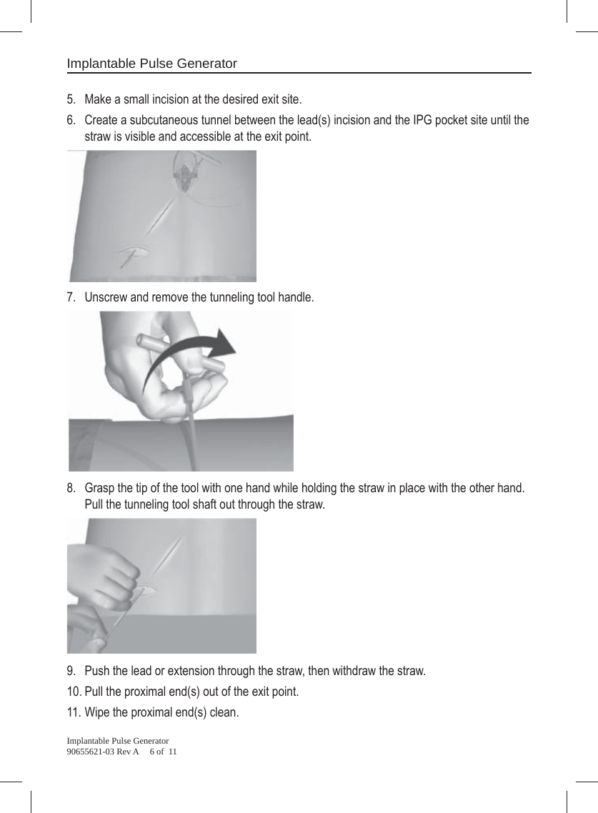
- 4. Additional User Manual 1
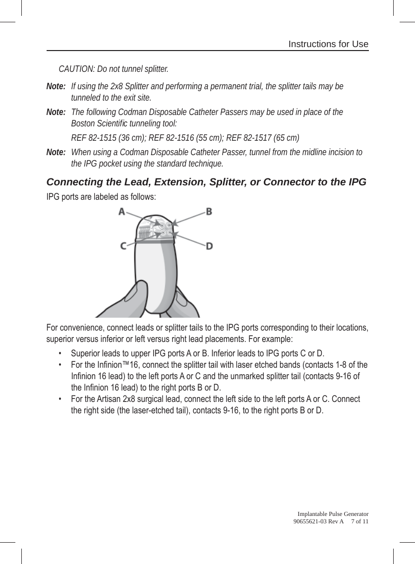
- 5. Additional User Manual 2
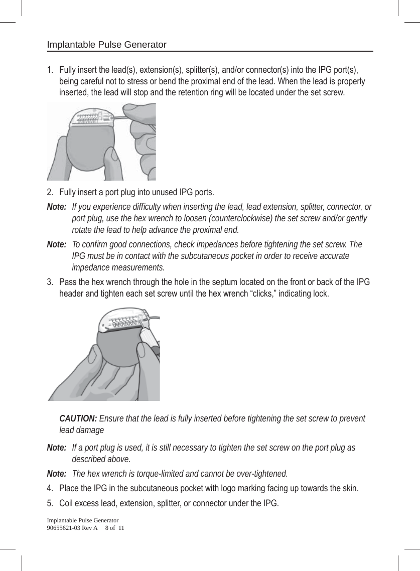
- 6. Additional User Manual 3
Additional User Manual 3