Boston Scientific CRM2920A05 Model 2920 & Model 2901 User Manual
Boston Scientific Corporation Model 2920 & Model 2901
UserManual.wiki
>
Boston Scientific
>
CRM2920A05 User Manual
>
User Manual
Contents
1.
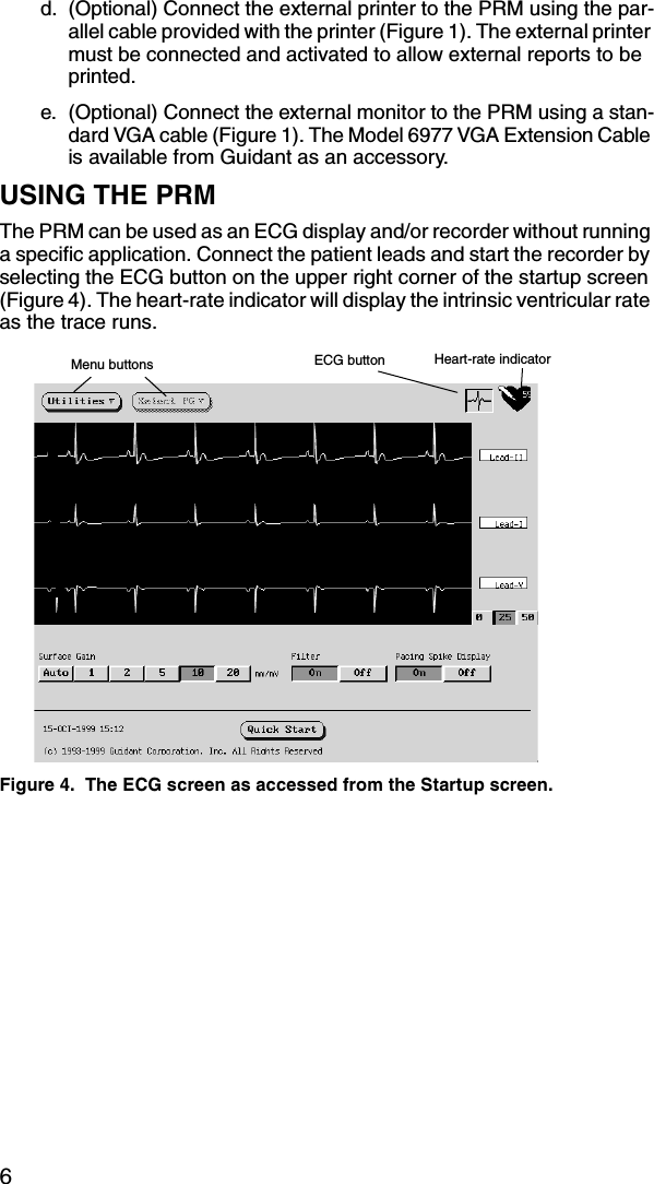
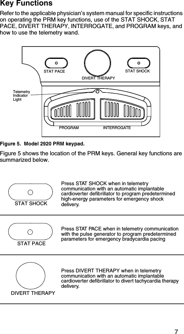
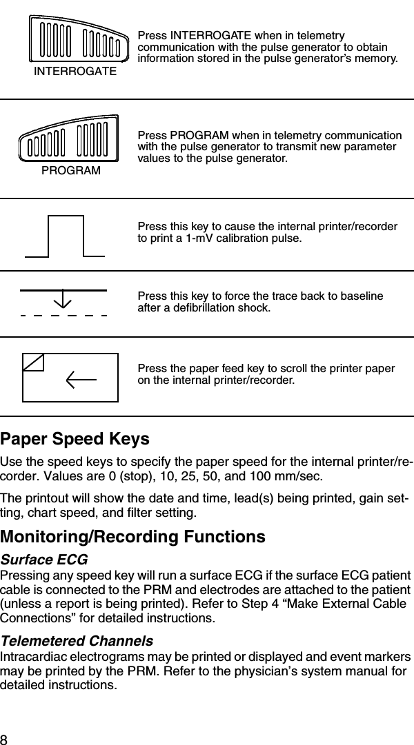
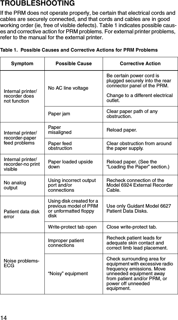
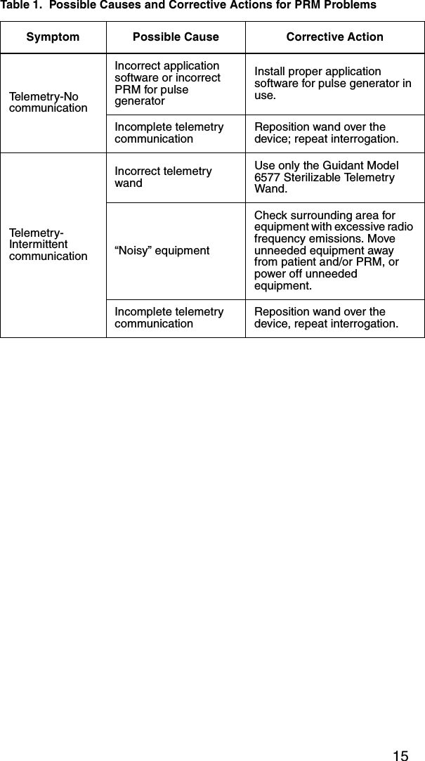
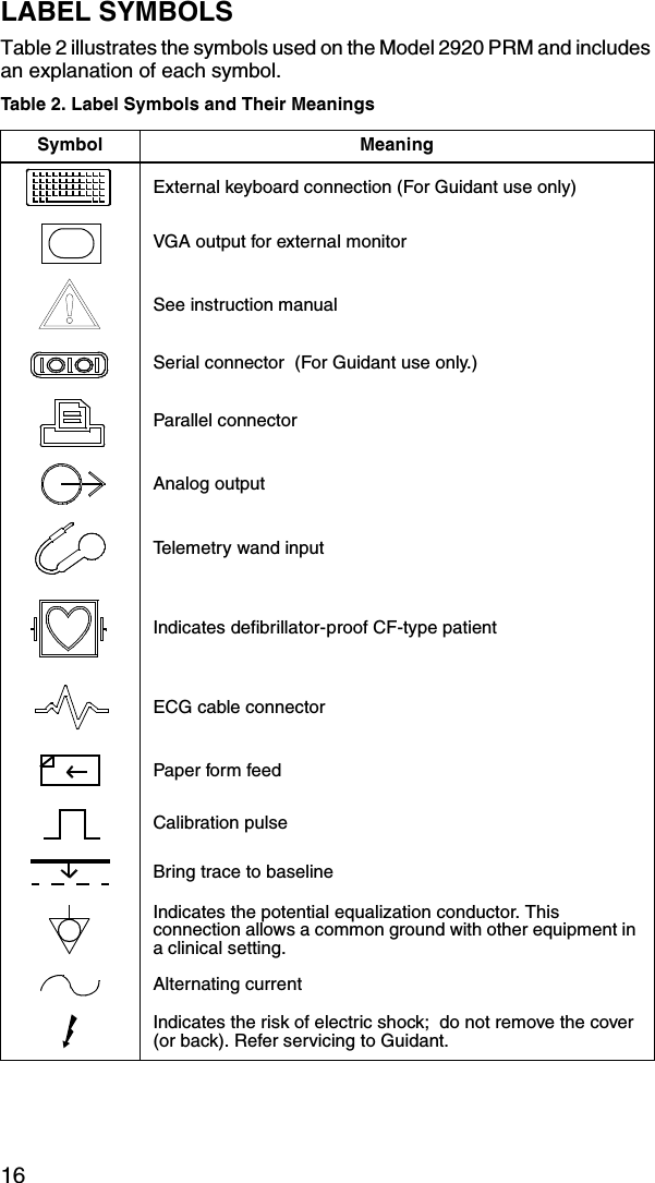
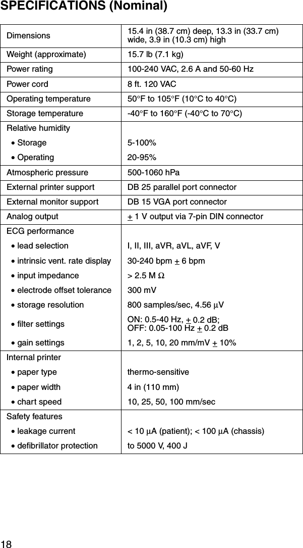
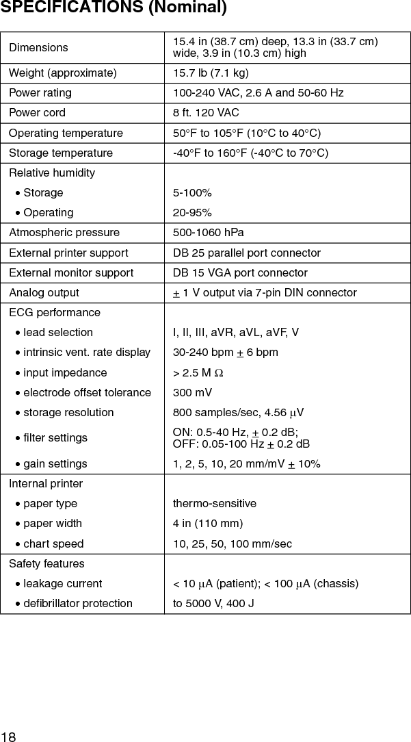
User Manual
2.
User Manual update
User Manual
Navigation menu
Upload a User Manual
Namespaces
Wiki Guide
HTML
PDF
Info
Views
User Manual
Discussion / Help
Navigation