Boston Scientific CRM312004 3120 User Manual prm
Boston Scientific Corporation 3120 prm
UserManual.wiki
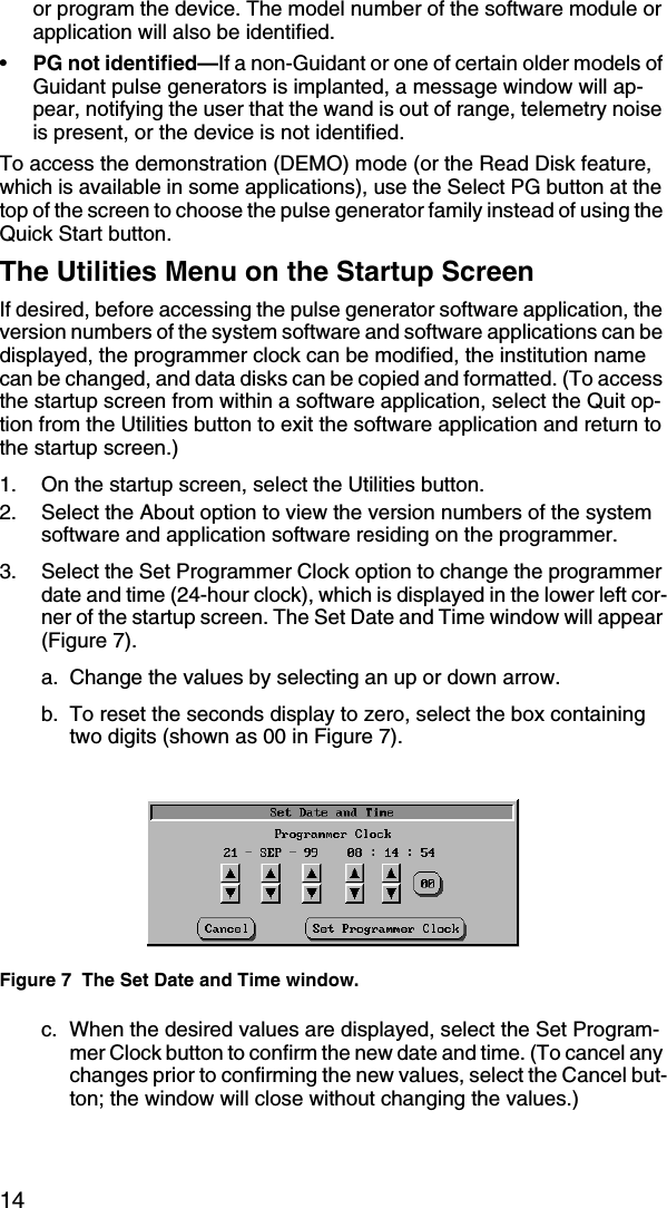
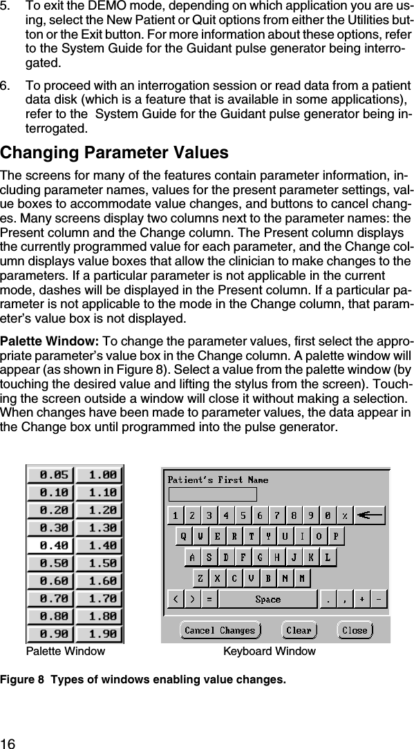
>
Boston Scientific
>
CRM312004 User Manual
>
User Manual
Contents
1.
User Manual
2.
Users Manual
User Manual
Navigation menu
Upload a User Manual
Namespaces
Wiki Guide
HTML
PDF
Info
Views
User Manual
Discussion / Help
Navigation
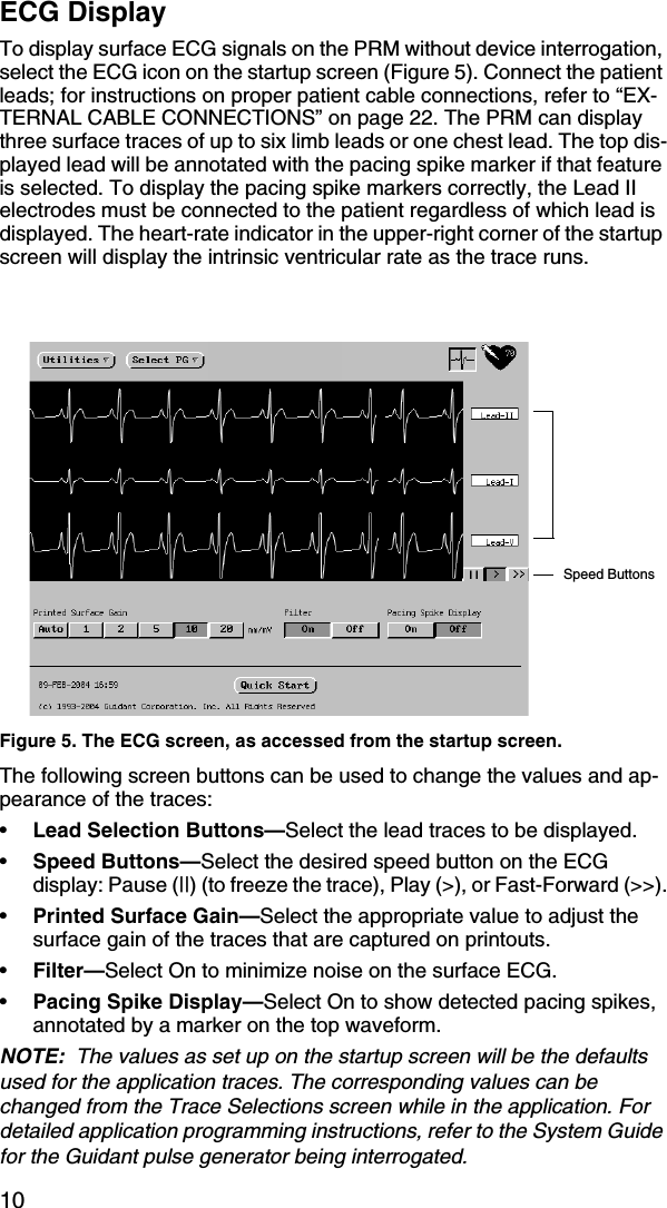
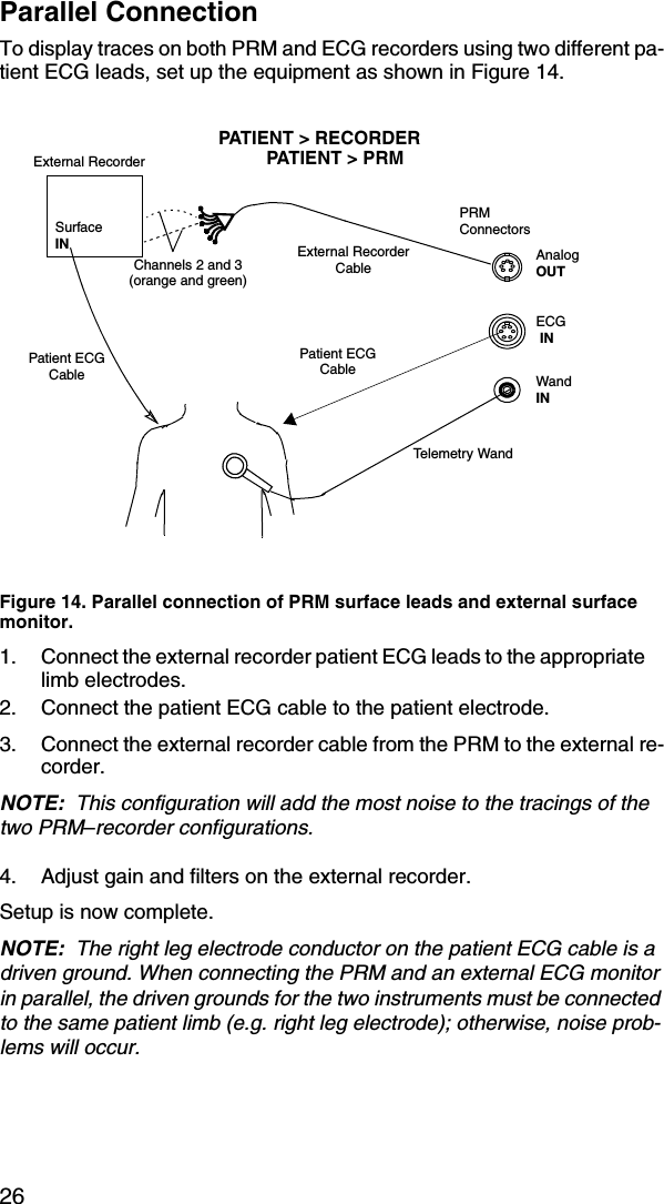
![21Safety and EMC Compliance StandardsThis equipment has been tested and found to comply with applicable safety portions of the following standards: • EN60601-1:1990 + A1:1993 + A2:1995• UL60601-1:2003• CAN/CSA-C22.2 No. 601.1-M90This equipment has been tested and found to comply with the limits for medical devices to IEC 60601-1-2: 2001 [or EN 60601-1-2: 2001 or Med-ical Device Directive 93/42/EEC]. This testing shows the device provides reasonable protection against harmful interference in a typical medical in-stallation. However, there is no guarantee that interference will not occur in a particular installation. If this equipment does cause harmful interfer-ence to other devices or is negatively impacted by other devices, the user is encouraged to try to correct the interference by one or more of the fol-lowing measures:• Reorient or relocate the devices• Increase the separation between the devices• Connect the equipment to an outlet on a different circuit• Consult the manufacturer or field service technician for help.This equipment has been tested an and found to comply with the following EMC standards:FCC Part 15CEN 300 330 -2 V 1.1The PRM is capable of continuous operation and will not shut off automat-ically if it is unused for an extended time or if it runs out of paper. Keep the air intake and outlet free from obstruction.CAUTION: The PRM is not water-proof or explosion-proof. It should not be used in the presence of flammable gas mixtures including anes-thetic mixture with air, oxygen, or nitrous oxide.PRM Storage1. If using a patient data disk, remove disk from the disk drive by pressing the disk ejection button (Figure 9), and store the disk in a safe place.2. Exit the current software application.3. Press the Power button to turn the power off (Figure 2).NOTE: Before unplugging the power cord to move the PRM, always exit the software application and press the Power button to turn off the PRM; otherwise, your system may lock up completely or have boot errors.](https://usermanual.wiki/Boston-Scientific/CRM312004.User-Manual/User-Guide-532938-Page-24.png)