Boston Scientific CRM314013 3140 User Manual
Boston Scientific Corporation 3140
User Manual
reference number
ZOOM® Wireless Transmitter reference guide
ZOOM® Wireless Transmitter reference guide
ZOOM® Wireless Transmitter reference guide
ZOOM® Wireless Transmitter reference guide
ZOOM® Wireless Transmitter reference guide
ZOOM® Wireless Transmitter reference guide
ZOOM® Wireless Transmitter reference guide
ZOOM® Wireless Transmitter reference guide
ZOOM® Wireless Transmitter reference guide
ZOOM® Wireless Transmitter reference guide
ZOOM® Wireless Transmitter reference guide
ZOOM® Wireless Transmitter reference guide
ZOOM® Wireless Transmitter reference guide
ZOOM® Wireless Transmitter reference guide
ZOOM® Wireless Transmitter reference guide
ZOOM® Wireless Transmitter reference guide
ZOOM® Wireless Transmitter reference guide
ZOOM® Wireless Transmitter reference guide
ZOOM® Wireless Transmitter reference guide

TABLE OF CONTENTS
DESCRIPTION AND USE .................................................................................................................................................. 1
INTENDED USE ............................................................................................................................................................... 1
CONTRAINDICATIONS .................................................................................................................................................... 1
WARNINGS ................................................................................................................................................................... 1
Use of unspeci ed cables and accessories ............................................................................................................. 1
Radio interference by other equipment ................................................................................................................ 1
Proximity to other equipment...............................................................................................................................2
ZWT and PRM must remain outside sterile eld....................................................................................................2
ZWT is MR Unsafe .................................................................................................................................................2
Modi cations ........................................................................................................................................................ 2
PRECAUTIONS ............................................................................................................................................................... 2
Connect only to Boston Scienti c Model 3120 PRM ............................................................................................. 2
Electrical and magnetic interference.....................................................................................................................2

MAINTENANCE AND HANDLING .................................................................................................................................... 3
Cleaning the ZWT ................................................................................................................................................. 3
Magnet handling .................................................................................................................................................. 3
ZWT use ................................................................................................................................................................3
Disconnecting the ZWT .........................................................................................................................................3
ZWT accessibility................................................................................................................................................... 3
ADVERSE EFFECTS ......................................................................................................................................................... 3
SYSTEM FEATURES........................................................................................................................................................ 4
SYSTEM COMPONENTS AND ACCESSORIES .................................................................................................................. 4
SYSTEM SERVICING AND REPAIR .................................................................................................................................. 4
PREPARING THE ZWT FOR USE ...................................................................................................................................... 5
BEGIN ZIP TELEMETRY ................................................................................................................................................... 6
USING THE ZWT ............................................................................................................................................................. 6
Operation ............................................................................................................................................................. 6
Storage ................................................................................................................................................................. 7

MAINTENANCE CHECK AND SAFETY MEASURES ........................................................................................................... 8
Maintenance Check ............................................................................................................................................... 8
Service .................................................................................................................................................................. 8
TROUBLESHOOTING ...................................................................................................................................................... 9
SYMBOLS ON PACKAGING ........................................................................................................................................... 10
ENVIRONMENTAL PROTECTION AND DISPOSAL .......................................................................................................... 11
COMPLIANCE STANDARDS........................................................................................................................................... 12
Safety Standards ................................................................................................................................................. 12
Electromagnetic Compatibility Standards ........................................................................................................... 12
IEC 60601-1-2:2007 Information ........................................................................................................................ 13
Electromagnetic Emissions and Immunity .......................................................................................................... 14
SPECIFICATIONS .......................................................................................................................................................... 20
ENVIRONMENTAL REQUIREMENTS.............................................................................................................................. 21

This literature is intended for use by professionals trained or experienced in device implant and/or follow-up procedures.
CAUTION: US Federal law restricts this device to sale by or on the order of a physician trained or experienced in device
implant and follow-up procedures.
ZOOM is a registered trademark of Boston Scienti c or its a liates. LATITUDE is a trademark of Boston Scienti c or its a liates.

DESCRIPTION AND USE
The ZOOM® LATITUDE™ Programming System, which includes Model 3120 Programmer/Recorder/Monitor (PRM), Model 3140 ZOOM® Wireless
Transmitter (ZWT), and accessories, is a portable cardiac rhythm management system designed to be used with Boston Scienti c implantable pulse
generators.
INTENDED USE
The ZWT is intended to be used as part of the ZOOM LATITUDE Programming System to communicate with Boston Scienti c implantable pulse genera-
tors. The PRM software controls all pulse generator communication functions. Refer to model-speci c pulse generator product literature for detailed
information about software application instructions.
CONTRAINDICATIONS
The ZWT is contraindicated for use with any pulse generator other than Boston Scienti c pulse generators. Refer to model-speci c pulse generator
product literature for other contraindications for use.
WARNINGS
Use of unspeci ed cables and accessories
The use of any cables or accessories with the ZWT other than those speci ed by Boston Scienti c in this manual may result in increased emissions or
decreased immunity of the ZWT. Anyone connecting such cables or accessories to the ZWT may be con guring a medical system and is responsible for
ensuring that the system complies with the requirements of IEC/EN 60601-1, Clause 16 for the medical electrical systems.
Radio interference by other equipment
Other equipment may interfere with the ZWT, even if that equipment complies with the International Special Committee on Radio Interference (CISPR)
emission requirements.
1

Proximity to other equipment
Do not use the ZWT adjacent to or stacked with other equipment. If adjacent or stacked use is necessary, check the ZWT for normal operation in that
con guration.
ZWT and PRM must remain outside sterile eld
The ZWT and the PRM are non-sterile and cannot be sterilized. They must both remain outside the sterile eld. Maintain a minimum operating
distance of 7.6 cm (3 in) between the ZWT and the PRM.
ZWT is MR Unsafe
The ZWT is MR Unsafe and must be kept outside MRI sites classi ed Zone III and above, as de ned by the American College of Radiology Guidance
Document for Safe MR Practices . Under no circumstances should the ZWT be brought into the MRI scanner room, the control room, or MRI site Zone III
or IV areas.
Modi cations
No modi cation of this equipment is allowed unless approved by Boston Scienti c.
PRECAUTIONS
Connect only to Boston Scienti c Model 3120 PRM
Connect the ZWT only to a Model 3120 Boston Scienti c PRM equipped with current level software.
Electrical and magnetic interference
Avoid establishing telemetry communication between the ZWT and the pulse generator when the ZWT is in close proximity to monitors,
high-frequency electrosurgical equipment, or strong magnetic elds. The telemetry link may be impaired.
2

MAINTENANCE AND HANDLING
Cleaning the ZWT
When necessary, clean the ZWT housing with a soft cloth lightly dampened with water, isopropyl alcohol, a 5% bleach solution, or window cleaner. Do
not allow any amount of cleaning solution or moisture to come in contact with the USB port. Do not use an abrasive cloth or volatile solvents to clean
any portion of the ZWT.
Magnet handling
Do not place a magnet on the ZWT.
ZWT use
The ZWT is not waterproof or explosion-proof and cannot be sterilized. Do not use it in the presence of ammable gas mixtures including anesthetics,
oxygen, or nitrous oxide.
Disconnecting the ZWT
Disconnect the USB cable from the ZWT unit to completely isolate it from the power source.
ZWT accessibility
Make certain that the USB connection point is accessible at all times so that power may be disconnected.
ADVERSE EFFECTS
None known.
3

SYSTEM FEATURES
The ZWT enables cordless, hands-free, 2-way radio frequency (RF) communication between the Model 3120 Programmer/Recorder/Monitor (PRM) and
Boston Scienti c pulse generators speci cally designed to use the Medical Implant Communications Service (MICS).
NOTE: The MICS telemetry feature is not available for all pulse generators. For more information, refer to the associated product literature for the pulse
generator being interrogated.
SYSTEM COMPONENTS AND ACCESSORIES
The ZOOM Wireless Transmitter system consists of Model 3140 ZOOM Wireless Transmitter and Model 3141 USB Cable.
CAUTION: The ZWT must be directly connected to either of the two 3120 PRM USB ports using only the Model 3141 USB cable. Do not use USB cables
other than the Model 3141. Intermittent or unreliable telemetry may result if the ZWT is connected to the PRM using an unapproved USB cable.
CAUTION: Do not connect the ZWT to any equipment other than Boston Scienti c Model 3120 PRM.
WARNING: The use of any cables or accessories with the ZWT other than those speci ed by Boston Scienti c in this manual may result in increased
emissions or decreased immunity of the ZWT. Anyone connecting such cables or accessories to the ZWT may be con guring a medical system and is
responsible for ensuring that the system complies with the requirements of IEC/EN 60601-1, Clause 16 for medical electrical systems.
SYSTEM SERVICING AND REPAIR
Unless otherwise agreed, the ZWT remains the property of Boston Scienti c and Boston Scienti c must perform all necessary servicing and repair work.
For additional information, contact Boston Scienti c using the information on the back cover.
4
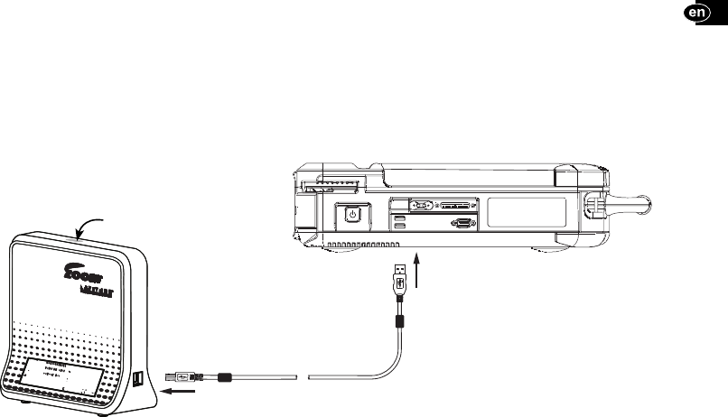
PREPARING THE ZWT FOR USE
Connect 3140 ZWT and 3120 PRM as shown below. Note
location of indicator light on top surface of ZWT.
The 3120 PRM may be powered on or o during 3140 ZWT installation.
Model 3140 ZWT
Model 3120 PRM
View of left side
ZWT indicator light
5

BEGIN ZIP TELEMETRY
NOTE: The MICS telemetry feature is not available for all pulse generators. For more information, refer to the associated product literature for the pulse
generator being interrogated.
1. Raise the PRM screen to a comfortable viewing angle.
2. Press the PRM On/O button.
3. Wait until both the PRM startup screen and the ZWT green indicator light appear, usually less than 60 seconds.
4. Place the telemetry wand over the pulse generator. Use either the Quick Start button on the PRM screen or the Select PG button located on
the toolbar below the startup screen to begin interrogation. Remove the wand once the telemetry indicator on the PRM is
illuminated.
For optimum MICS telemetry communication, position the ZWT at least 7.6 cm (3 in) away from the PRM. Remove any obstructions between the two
instruments. Repositioning the ZWT may improve MICS telemetry performance. If MICS telemetry performance is not satisfactory, use the telemetry
wand instead.
USING THE ZWT
Operation
The ZWT requires special handling. To protect the ZWT from damage, refer to the following information:
• Do not subject the ZWT to abusive shocks or vibrations.
• When transporting the ZWT from an outside environment to an inside environment, allow the ZWT to come to ambient temperature before
use.
• Do not place a magnet on the ZWT.
• Do not pour or splash liquid into or onto the ZWT.
6

• Do not disassemble the ZWT.
• Disconnect the USB cable prior to transporting the ZWT.
Operate the ZWT and accessories within the following conditions:
• Temperature range of 10°C to 35°C (50°F to 95°F)
• Humidity between 25% and 90%
Transport and store the ZWT within the following conditions:
• Temperatures between -40°C and 70°C (-40°F and 158°F)
• Relative humidity between 25% and 95%
• Atmospheric pressure between 50 kPa to 106 kPa (7.252 psi to 15.374 psi)
The ZWT is capable of continuous operation and will not shut o automatically if it is unused for an extended time.
CAUTION:
The ZWT is not waterproof or explosion-proof and cannot be sterilized. Do not use it in the presence of ammable gas mixtures including anesthetic
mixture with air, oxygen, or nitrous oxide.
Storage
1. Unplug the USB cable.
2. Protect the ZWT and the USB cable from damage.
3. Store the system at -40°C to 70°C (-40°F to 158°F) temperature and 25% to 95% relative humidity.
7

MAINTENANCE CHECK AND SAFETY MEASURES
Maintenance Check
Prior to each use, perform a visual inspection and verify the following:
• Mechanical integrity of the ZWT and its USB cable.
• Legibility and adhesion of the ZWT labels.
The ZWT contains no user-accessible components and must be returned to Boston Scienti c for repair or replacement of any internal components.
Safety Measurements
National regulations may require that the user, manufacturer, or manufacturer representative periodically perform and document safety tests of the
device. If such testing is required in your country, follow the testing interval and extent of testing as regulated in your country. If you do not know the
national regulations in your country, please contact your local Boston Scienti c representative.
Service
For questions regarding operation or repair of the ZWT, contact Boston Scienti c using the information on the back cover.
The ZWT must be serviced by Boston Scienti c personnel only.
If the ZWT malfunctions and requires repair, help to ensure e cient service by following these guidelines:
1. Leave the con guration of the instrument exactly as it was at the time of malfunction. Contact Boston Scienti c using the information on
the back cover of this manual.
1. Write a detailed description of the malfunction(s).
2. If the ZWT must be returned to Boston Scienti c for service, pack it in the shipping container in which it was received or in a shipping
container provided by Boston Scienti c.
3. Contact Boston Scienti c using the information on the back cover of this manual to obtain the proper ship-to address.
8

TROUBLESHOOTING
If the ZWT does not operate properly, check that the USB cable is securely connected to both the ZWT and the PRM. Also check that the PRM cords and
cables are free of visible defects and are properly connected. Possible causes and corrective actions for ZWT problems are shown below.
Symptom Possible Cause Corrective Action
Green indicator light on ZWT
does not light within 60 seconds
of powering on PRM
USB cable not securely connected to ZWT
and PRM
Remove and reconnect both ends of USB cable. Reposition
wand over the pulse generator and repeat interrogation.
USB cable damaged Replace with Model 3141 USB Cable only.
ZWT fault Contact Boston Scienti c representative.
Intermittent or no RF telemetry
communication
Telemetry RF signal obstructed Assure that a clear line-of-sight path exists between ZWT
and pulse generator. Repeat interrogation.
Telemetry RF signal interference Reposition or reorient ZWT at least 7.6 cm (3 in) away from
PRM. Repeat interrogation.
USB cable not securely connected to ZWT
and PRM
Remove and reconnect both ends of USB cable. Reposition
wand over the pulse generator and repeat interrogation.
RF Telemetry fails Reposition wand over pulse generator; repeat interrogation.
PRM software version not current Contact Boston Scienti c representative.
9
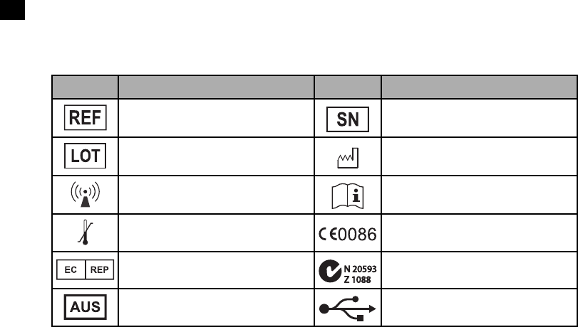
SYMBOLS ON PACKAGING
The following symbols may be used on packaging and labeling:
Symbol Description Symbol Description
Reference number Serial number
Lot number Date of manufacture
Non-ionizing electromagnetic radiation Consult instructions for use
Temperature limitation CE mark of conformity with the identi cation of the
noti ed body authorizing use of the mark
Authorized Representative in the European Com-
munity
C-tick with supplier codes
Meets Australia and New Zealand EMC requirements
Australian Sponsor Address Universal Serial Bus (USB)
10
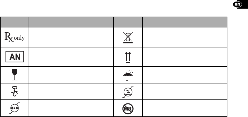
Symbol Description Symbol Description
RESTRICTED DEVICE. Federal law (USA) restricts the
sale, distribution, or use of this device to, by, or on the
lawful order of a physician
Waste, Electrical, and Electronic Equipment (WEEE).
Discard with electronic waste.
Assembly number This side up
Fragile, handle with care Keep dry
Do not use hooks Humidity limitations
Atmospheric pressure limitations Magnetic Resonance Unsafe
11

ENVIRONMENTAL PROTECTION AND DISPOSAL
Return the ZWT and accessories to Boston Scienti c at the end of their useful lives for appropriate disposal.
COMPLIANCE STANDARDS
The following standards apply to the ZWT:
Safety Standards
This equipment has been tested and found to comply with applicable safety portions of the following standards:
• IEC 60601-1:2005 + C1:2006 + C2:2007 + INT1:2008 + INT2:2009
• ANSI/AAMI ES60601-1:2005 + C1:2009 + A2:2010
• BS EN 60601-1:2006 + C1:2006 + C2:2007 + C3:2010
• CAN/CSA-C22 No. 60601-1-08
Electromagnetic Compatibility Standards
This equipment has been tested and found to comply with the applicable portions of the following electromagnetic compatibility (EMC) standards:
• EN 301 489-1 v1.9.2:2011
• EN 301 489-27 v1.1.1:2004
• EN 301 839-2 v1.3.1:2009
• IC RSS-243:2010
NOTE: Use special precautions regarding EMC during the installation and the use of the ZWT, according to the EMC instructions given throughout this
manual. Refer to the details about the ZWT electromagnetic emissions and immunity.
NOTE: Use caution when using RF portable and mobile equipment in close proximity to the ZWT. Refer to the details about the ZWT electromagnetic
immunity.
12

FCC: This transmitter is authorized by rule under the Medical Device Radiocommunication Service (in part 95 of the FCC Rules) and must not cause
harmful interference to stations operating in the 400.150–406.000 MHz band in the Meteorological Aids ( i.e., transmitters and receivers used to
communicate weather data), the Meteorological Satellite, or the Earth Exploration Satellite Services and must accept interference that may be caused
by such stations, including interference that may cause undesired operation. This transmitter shall be used only in accordance with the FCC Rules gov-
erning the Medical Device Radiocommunication Service. Analog and digital voice communications are prohibited. Although this transmitter has been
approved by the Federal Communications Commission, there is no guarantee that it will not receive interference or that any particular transmission
from this transmitter will be free from interference. FCC ID#: ESCCRM314013
Industry Canada: This device complies with Industry Canada license–exempt RSS standard(s). Operation is subject to the following two conditions:
1) this device may not cause harmful interference, and 2) must accept any interference received, including interference that may cause undesired
operation. This device may not interfere with stations operating in the 400.150–406.000 MHz band in the meteorological aids, meteorological–satel-
lite, and earth–exploration satellite services, and must accept any interference received, including interference that may cause undesired operation.
IC# 4794A-CRM31403
CAUTION: Changes or modi cations not expressly approved by Boston Scienti c could void the user’s authority to operate the equipment.
R&TTE: Boston Scienti c hereby declares that this transmitter is in compliance with the essential requirements and other relevant provisions of Direc-
tive 1999/5/EC. To obtain a full text Declaration of Conformity, contact Boston Scienti c using the information on the back cover.
NOTE: As with other telecommunications equipment, verify national data privacy laws.
IEC 60601-1-2:2007 Information
This equipment has been tested and found to comply with the applicable limits for medical devices in ANSI/AAMI/IEC 60601-1-2:2007. This testing
shows the device provides reasonable protection against harmful interference in a typical medical installation. However, there is no guarantee that
interference will not occur in a particular installation.
13

If this equipment does cause harmful interference to other devices or is negatively impacted by other devices, try to correct the interference by one or
more of the following measures:
• Reorient or relocate the devices
• Increase the separation between the devices
• Connect the equipment to an outlet on a di erent circuit
• Consult the manufacturer or eld service technician for help
Electromagnetic Emissions and Immunity
The ZWT was determined to have no essential performance. Nevertheless, functions related to communication with the implanted pulse generator
were included in testing.
Table 1: Guidance and manufacturer’s declaration — electromagnetic emissions and environment
Guidance and manufacturer’s declaration – electromagnetic emissions
The ZWT is intended for use in the electromagnetic environment speci ed below. The customer or the user of the ZWT should ensure that it is used
in such an environment.
Emissions test Compliance Electromagnetic environment – guidance
RF emissions (CISPR 11) Group 1 The ZWT uses RF energy only for its internal function. Therefore,
its RF emissions are very low and are not likely to cause any
interference in nearby electronic equipment.
14

Guidance and manufacturer’s declaration – electromagnetic emissions
RF emissions (CISPR 11) Class A The ZWT is suitable for use in all establishments other than
domestic and those directly connected to the public low-voltage
power supply network that supplies buildings used for domestic
purposes.
Harmonic emissions (IEC 61000-3-2) Class A
Voltage uctuations / icker emissions (IEC 61000-3-3) Complies
Table 2: Guidance and manufacturer’s declaration — electromagnetic immunity and environment
Guidance and manufacturer’s declaration – electromagnetic immunity
The ZWT is intended for use in the electromagnetic environment speci ed below. The customer or the user of the ZWT should ensure that it is used
in such an environment.
Immunity test IEC 60601 test level Compliance level Electromagnetic environment –
guidance
Electrostatic discharge (ESD)
(IEC 61000-4-2)
±6 kV contact
±8 kV air
±6 kV contact
±8 kV air
Floors should be wood, concrete, or ceramic tile.
If oors are covered with synthetic material, the
relative humidity should be at least 30%.
Electrical fast transient /
burst (IEC 61000-4-4)
±2 kV for power-supply lines
±1 kV for input/output lines
±2 kV for power-supply lines
±1 kV for input/output lines
Mains power quality should be that of a typical
commercial or hospital environment.
Surge (IEC 61000-4-5) ±1 kV line(s) to line(s)
±2 kV line(s) to earth
±1 kV di erential mode
±2 kV common mode
Mains power quality should be that of a typical
commercial or hospital environment.
15

Guidance and manufacturer’s declaration – electromagnetic immunity
Immunity test IEC 60601 test level Compliance level Electromagnetic environment –
guidance
Voltage dips, short interrup-
tions, and voltage variations
on power-supply input lines
(IEC 61000-4-11)
<5% UT (>95% dip in UT )
for 0.5 cycleb.
40% UT (60% dip in UT ) for
5 cycles
70% UT (30% dip in UT ) for
25 cycles
<5%UT (>95% dip in UT )
for 5 sec
<5% UT (>95% dip in UT )
for 0.5 cycleb.
40% UT (60% dip in UT ) for
5 cycles
70% UT (30% dip in UT ) for
25 cycles
<5%UT (>95% dip in UT )
for 5 sec
Mains power quality should be that of a typical
commercial or hospital environment. If the user
of the ZWT requires continued operation during
power mains interruptions, it is recommended
that the PRM to which the ZWT is connected be
powered from an uninterruptible power supply
or a battery.
Power frequency (50/60
Hz) magnetic eld (IEC
61000-4-8)
3 A/m 3 A/m Power frequency magnetic elds should be at
levels characteristic of a typical location in a typi-
cal commercial or hospital environment.
Note: UT is the AC mains voltage prior to application of the test level.
16
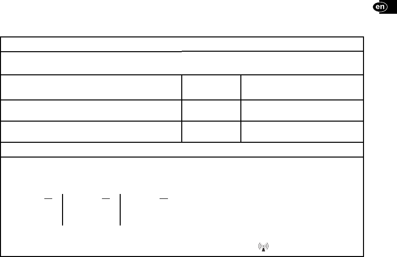
Table 3: Guidance and manufacturer’s declaration — electromagnetic immunity
Guidance and manufacturer’s declaration – electromagnetic immunity
The ZWT is intended for use in the electromagnetic environment speci ed below. The customer or the user of the ZWT should ensure that it is used
in such an environment.
Immunity test IEC 60601 test
level Compliance level
Conducted RF
(IEC 61000-4-6)
3 Vrms
150 kHz to 80 MHz 3 Vrms
Radiated RF
(IEC 61000–4-3)
3 V/m
80 MHz to 2.5 GHz 3 V/m
Electromagnetic environment – guidance
Portable and mobile RF communications equipment should be used no closer to any part of the ZWT, including cables, than the recommended
separation distance calculated from the equation applicable to the frequency of the transmitter.
Recommended separation distance:
√ P
d
= 1.2 *√ P
d
= 1.2 *√ P
d
= 2.3 *
150 KHz to 80 MHz 80 MHz to 800 MHz 800 MHz to 2.5 GHz
where P is the maximum output power rating of the transmitter in
watts (W) according to the transmitter manufacturer and d is the
recommended separation distance in meters (m).
Field strengths from xed RF transmitters, as determined by an electromagnetic site survey,a should be less than the compliance level in each
frequency range.b Interference may occur in the vicinity of equipment marked with the following symbol:
17

NOTE 1 At 80 MHz and 800 MHz, the higher frequency range applies.
NOTE 2 These guidelines may not apply in all situations. Electromagnetic propagation is a ected by absorption and re ection from structures,
objects, and people.
a. Field strengths from xed transmitters, such as base stations for radio (cellular/cordless) telephones and land mobile radios, amateur radio,
AM and FM radio broadcast, and TV broadcast cannot be predicted theoretically with accuracy. To assess the electromagnetic environment due to
xed RF transmitters, an electromagnetic site survey should be considered. If the measured eld strength in the location in which the ZWT is used
exceeds the applicable RF compliance level above, the ZWT should be observed to verify normal operation. If abnormal performance is observed,
additional measures may be necessary, such as reorienting or relocating the ZWT.
b. Over the frequency range 150 kHz to 80 MHz, eld strengths should be less than 3 V/m.
18
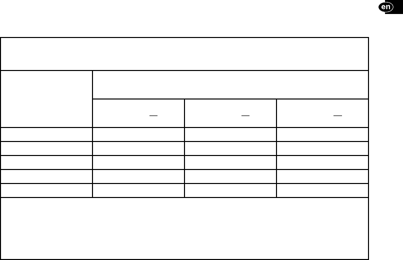
Table 4: Recommended separation distances between portable and mobile RF communications equipment and the ZWT
The ZWT is intended for use in an electromagnetic environment in which radiated RF disturbances are controlled. The customer or the user of the
ZWT can help prevent electromagnetic interference by maintaining a minimum distance between portable and mobile RF communications equip-
ment (transmitters) and the ZWT as recommended in this table, according to the maximum output power of the communications equipment.
Rated maximum output
power of transmitter
W
Separation distance according to frequency of transmitter
m
150 kHz to 80 MHz
√ P
d
= 1.2 *
80 MHz to 800 MHz
√ P
d
= 1.2 *
800 MHz to 2.5 GHz
√ P
d
= 2.3 *
0.01 0.12 0.12 0.23
0.1 0.38 0.38 0.73
1 1.2 1.2 2.3
10 3.8 3.8 7.3
100 12 12 23
For transmitters rated at a maximum output power not listed in the table, the recommended separation distance d in meters (m) can be estimated
using the equation applicable to the frequency of the transmitter, where P is the maximum output power rating of the transmitter in watts (W)
according to the transmitter manufacturer.
NOTE 1 At 80 MHz and 800 MHz, the separation distance for the higher frequency range applies.
NOTE 2 These guidelines may not apply in all situations. Electromagnetic propagation is a ected by absorption and re ection from structures,
objects, and people.
19

SPECIFICATIONS
Characteristic Nominal
Ingress protection rating IPX0
Dimensions (overall) 17.6 cm (6.9 in) wide, 17.3cm (6.8 in) high, 7.6 cm (3 in) deep
Weight (approximate) .6 kg (1.3 lb)
Power rating 5 V DC
Power cord Power supplied via USB data cable
Duty cycle Continuous
Frequency band 402 – 405 MHz (MICS/MedRadio)
Bandwidth < 300 KHz
Modulation FSK
E ective radiated power 25 μW (-16 dBm)
20

ENVIRONMENTAL REQUIREMENTS
Characteristic Nominal
Operating temperature 10°C to 35°C (50°F to 95°F)
Transport and storage temperature -40°C to 70°C (-40°F to 158°F)
Operating humidity 25% to 90%
Transport and storage humidity 25% to 95%
Operating altitude <= 2000 m
Transport and storage atmospheric pressure 50 kPa to 106 kPa (7.252 psi to 15.374 psi)
21

22


1

2

3


1

2

3


1

2

3


1

2

3


1

2

3


1

2

3


1

2

3


1

2

3


1

2

3


1

2

3


1

2

3


1

2

3


1

2

3


1

2

3


1

2

3


1

2

3


1

2

3


1

2

3

Boston Scientifi c
4100 Hamline Avenue North
St. Paul, MN 55112-5798 USA
Guidant Europe NV/SA; Boston Scientifi c
Green Square, Lambroekstraat 5D
1831 Diegem, Belgium
1.800.CARDIAC (227.3422)
+1.651.582.4000
Boston Scientifi c (Australia) Pty Ltd
PO Box 332
BOTANY NSW 1455 Australia
Free Phone 1 800 676 133
Free Fax 1 800 836 666
manufacturer
representative in the
european community
australian sponsor address
Authorized 2013
© 2013 Boston Scientifi c or its affi liates.
All rights reserved. 359093-001 ML 2013-01
*359093-001*
MADE IN CHINA