Boston Scientific CRM320014 3200 User Manual
Boston Scientific Corporation 3200
UserManual.wiki
>
Boston Scientific
>
CRM320014 User Manual
User Manual
Navigation menu
Upload a User Manual
Namespaces
Wiki Guide
HTML
PDF
Info
Views
User Manual
Discussion / Help
Navigation
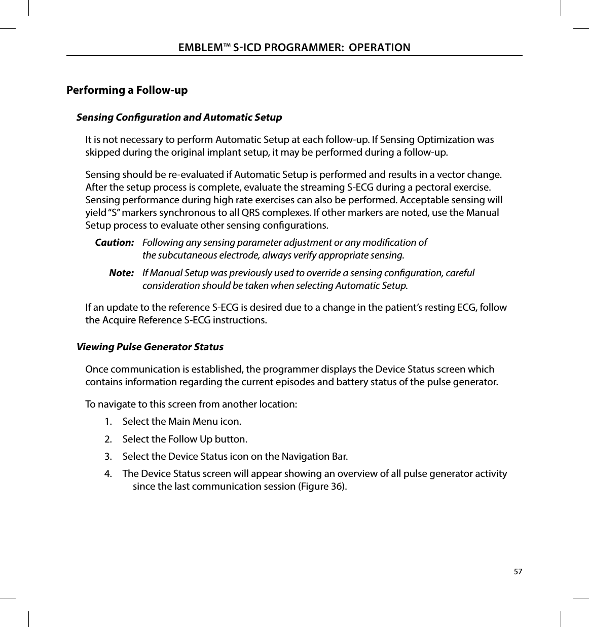
![5EMBLEM™ SICD PROGRAMMER: GENERAL DESCRIPTIONDisconnecting the programmer� Mains isolation is achieved by disconnecting the external power supply power cord from the AC electrical outlet. Do not position the programmer or the external power supply in a manner that would make it dicult to disconnect that cord.Programmer use� The programmer is not waterproof or explosion-proof and cannot be sterilized. Do not use it in the presence of ammable gas mixtures containing anesthetics, oxygen, or nitrous oxide.Conrm communication� Conrm that the programmer is in communication with the intended implanted S-ICD pulse generator.Electrostatic discharge� The programmer may be aected by ESD. If ESD occurs and the programmer’s functionality is aected, attempt to reset the programmer or contact Boston Scientic for instructions. Do not touch or connect the telemetry wand to the programmer unless ESD precautionary procedures are used.S-ICD System Warnings and PrecautionsThe following warnings and precautions apply to the S-ICD System as a whole. For additional warnings and precautions that are specic to other individual components of the system, and/or to the process of implanting the system, refer to the manual of the relevant system component (pulse generator, subcutaneous electrode, or electrode insertion tool [EIT]). S-ICD System WarningsGeneralComponent Compatibility� All Boston Scientic S-ICD implantable components are designed for use with the Boston Scientic or Cameron Health S-ICD System only. Connection of any S-ICD System components to a non-compatible component will result in failure to deliver life-saving debrillation therapy. Backup debrillation protection� Always have external debrillation equipment and medical personnel skilled in CPR available during implant and follow up testing. If not terminated in a timely fashion, an induced ventricular tachyarrhythmia can result in the patient’s death.](https://usermanual.wiki/Boston-Scientific/CRM320014/User-Guide-2422872-Page-11.png)
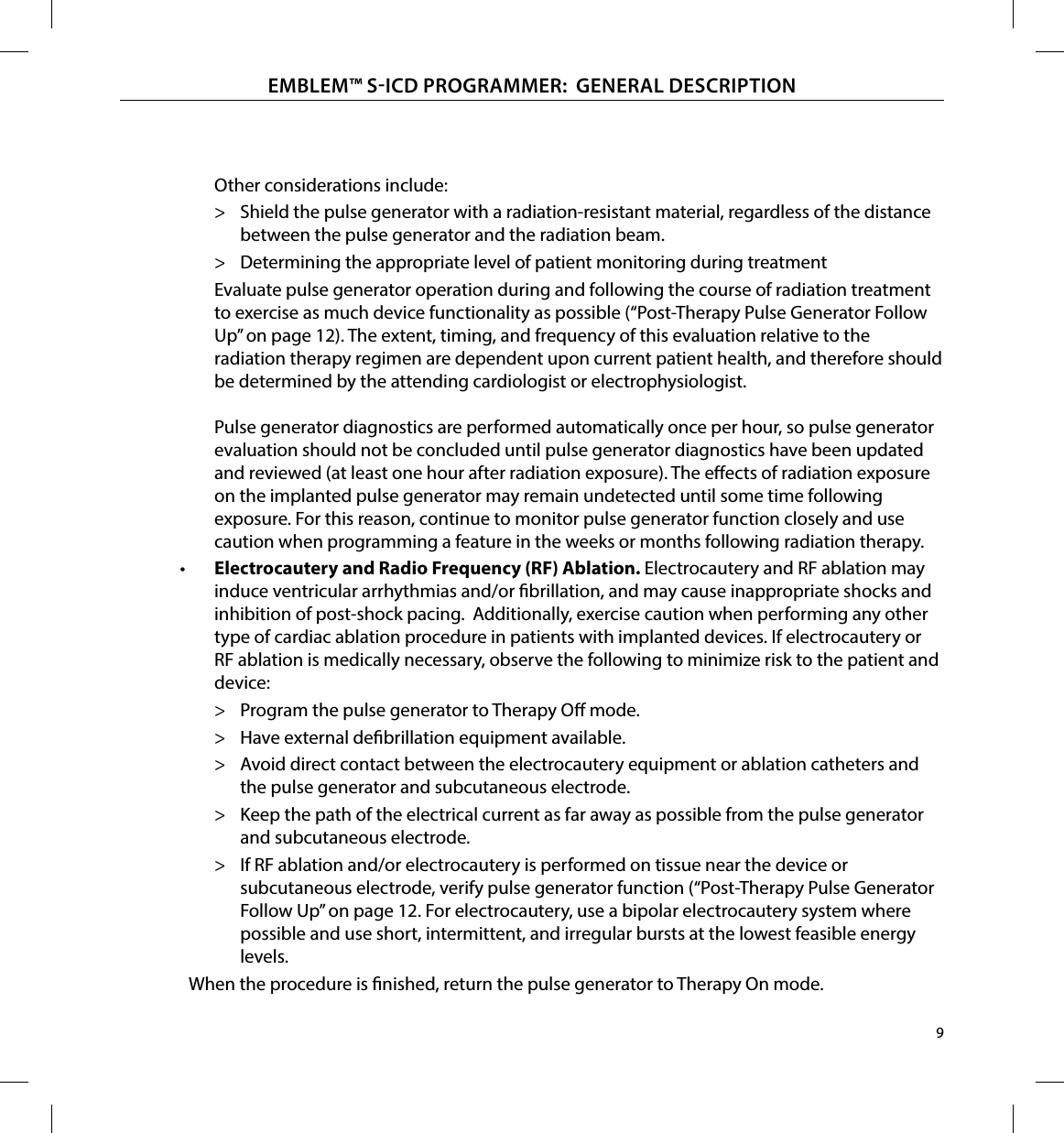
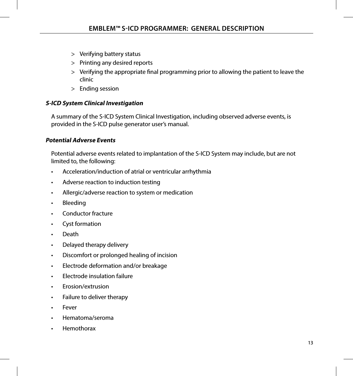

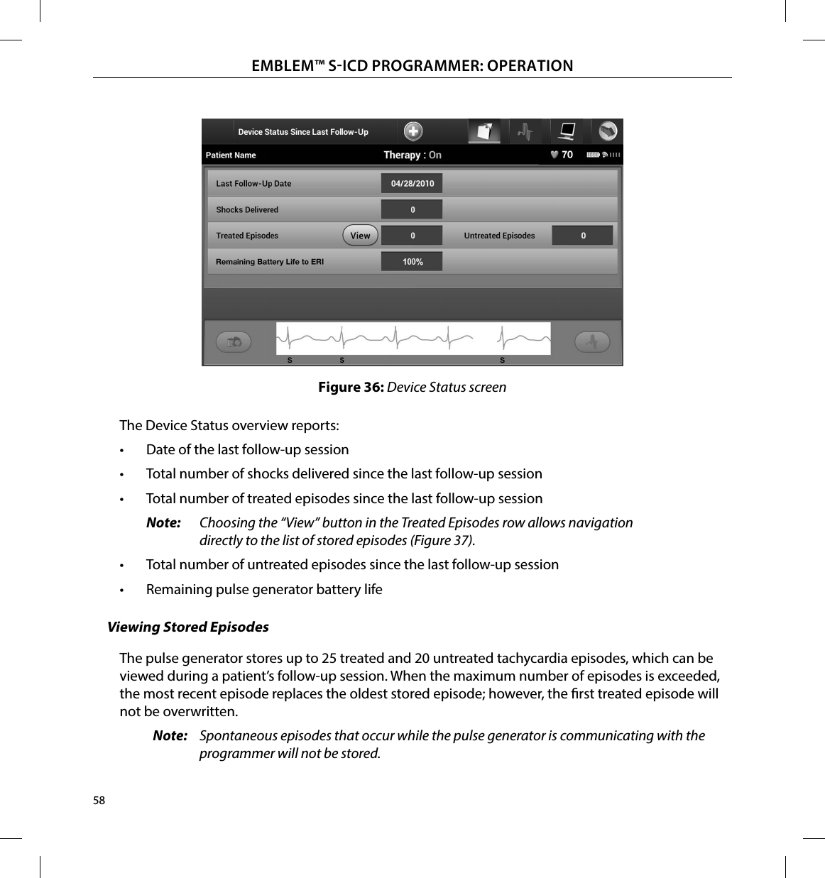
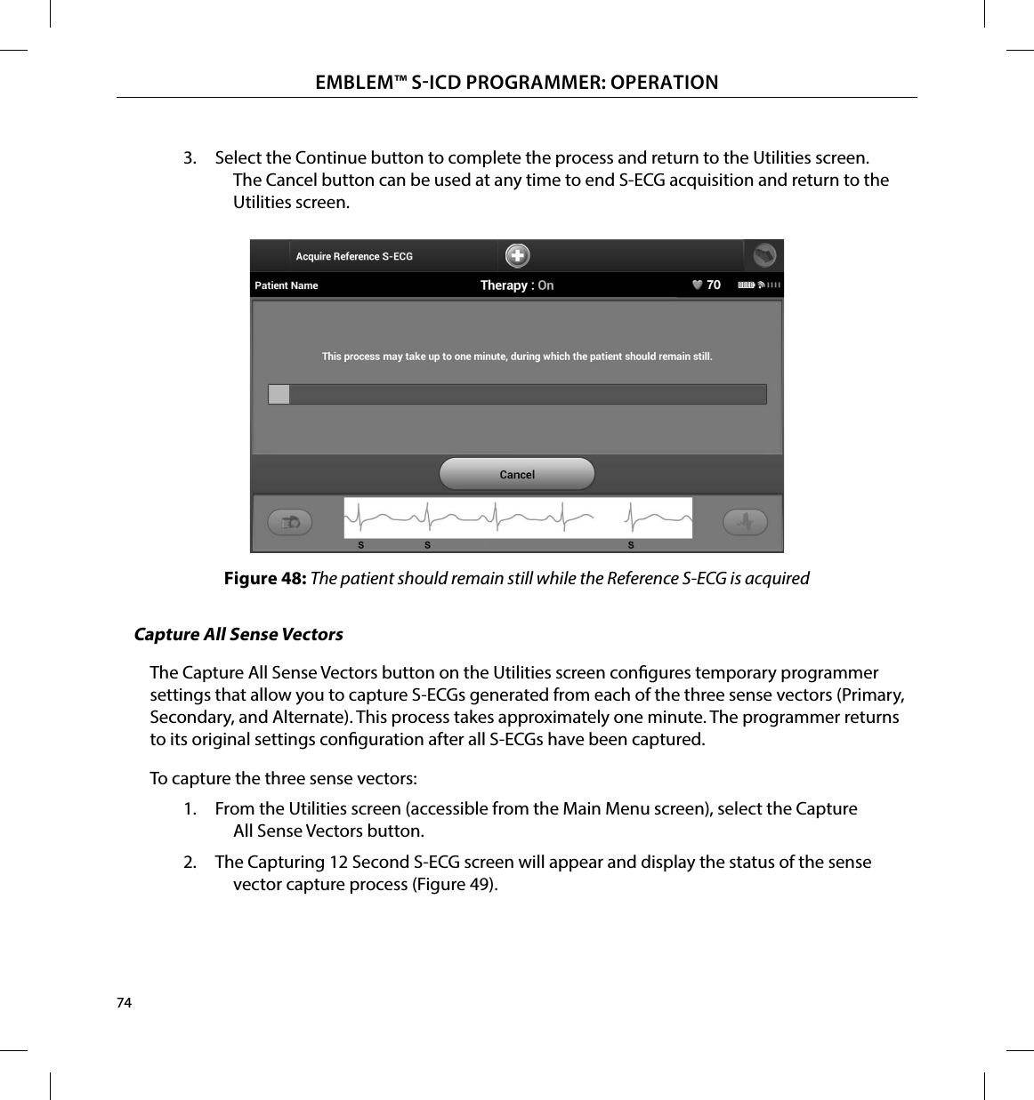
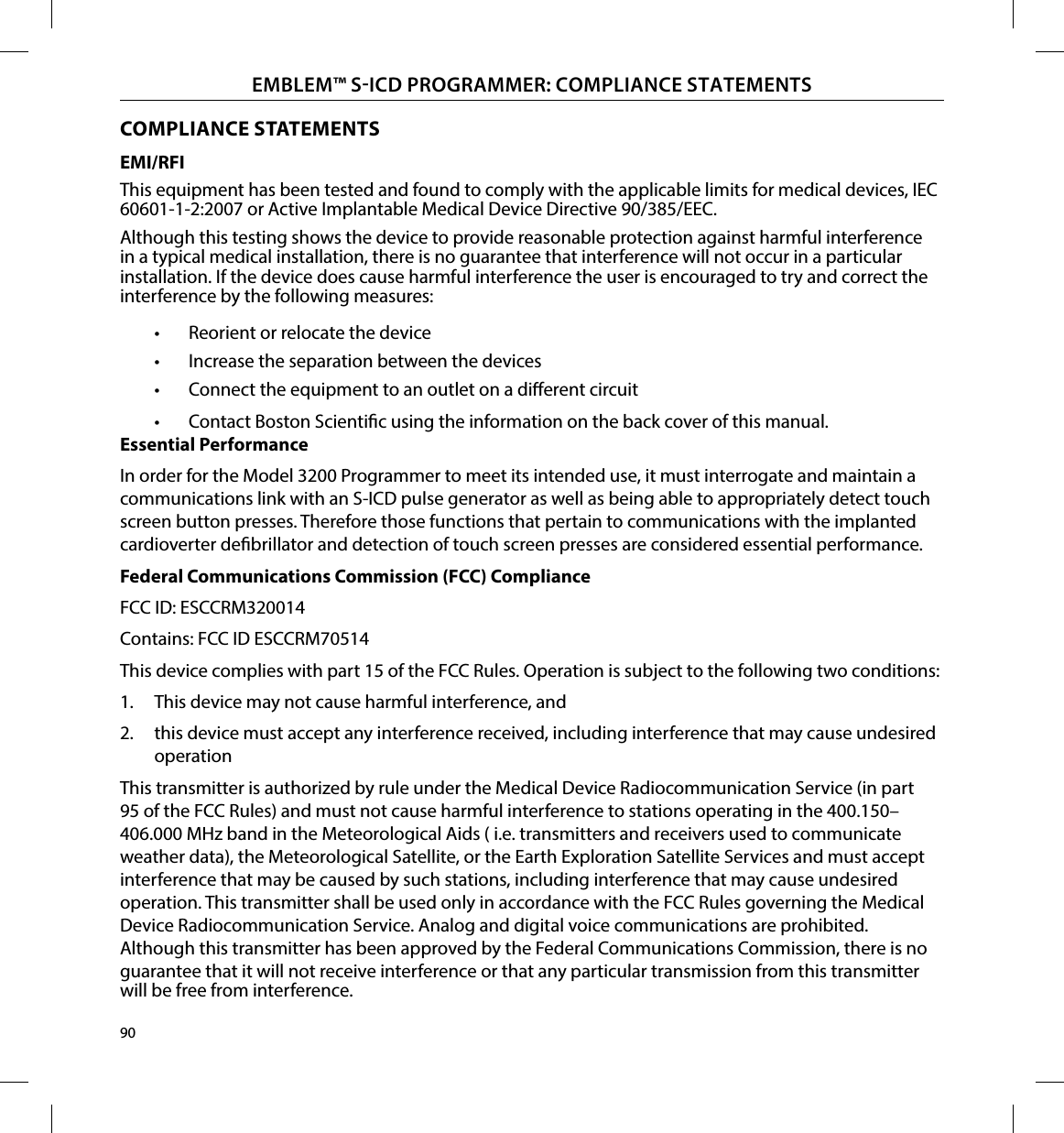

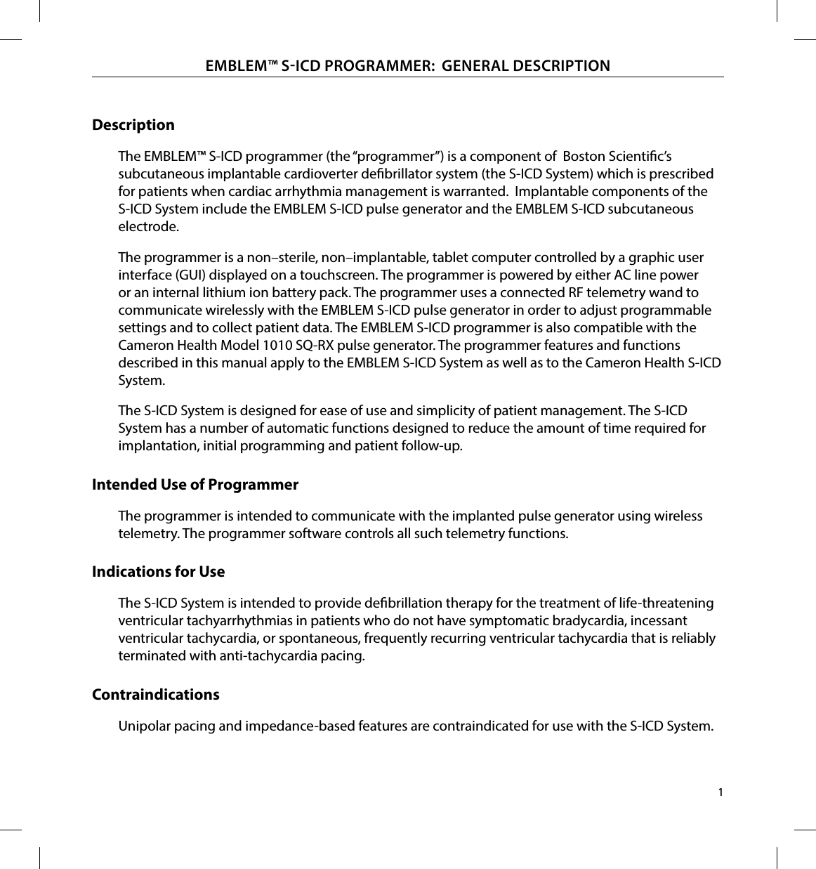
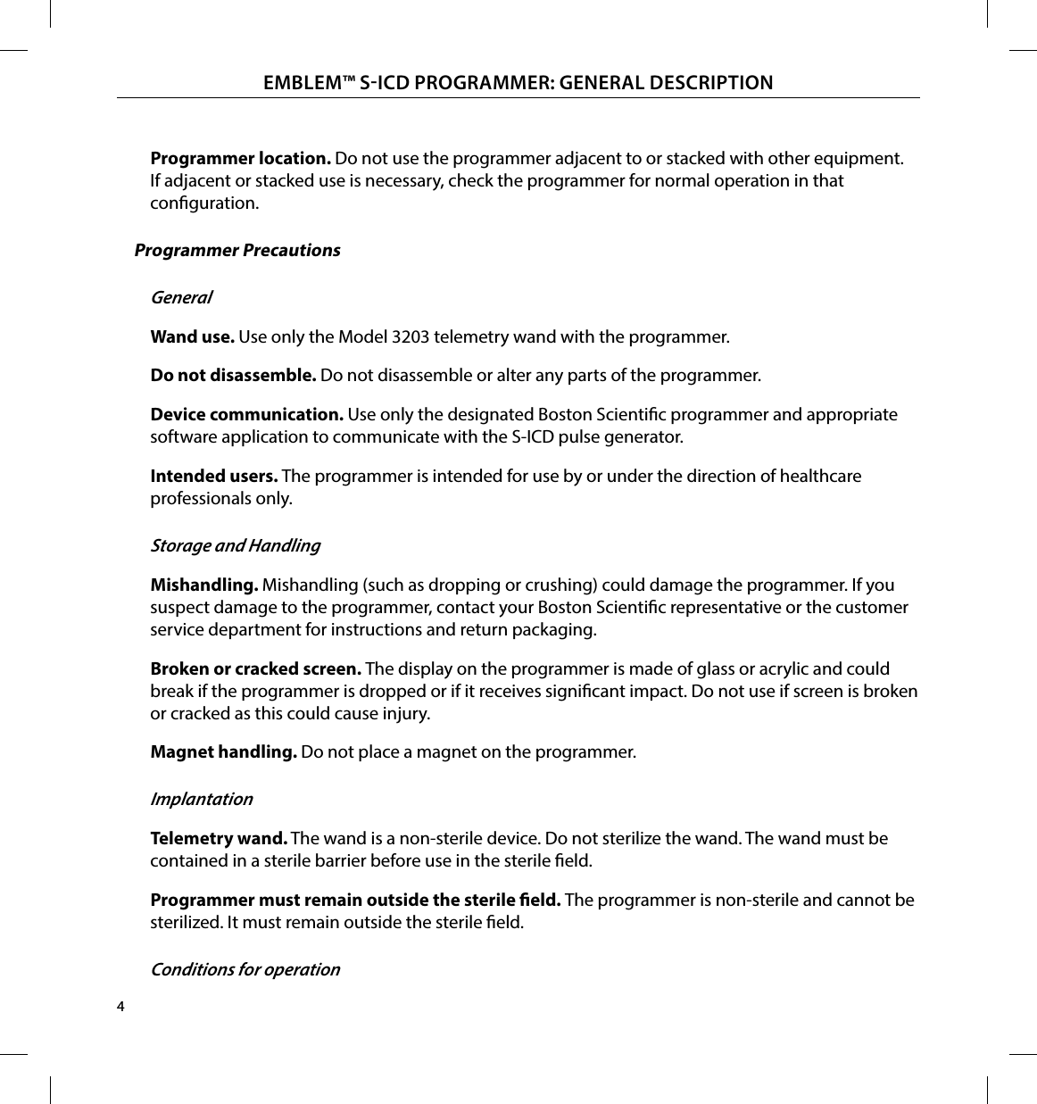
![93EMBLEM™ SICD PROGRAMMER: DECLARATIONS TABLESTable 5: Declaration Electromagnetic Immunity Part 2The Model 3200 programmer is intended for use in the electromagnetic environment specied below. The customer or the user of the Model 3200 programmer should assure that it is used in such an environment.Immunity Test IEC 60601 Test LevelCompliance LevelElectromagnetic Environment GuidanceConducted RFIEC 61000-4-63 Vrms150 kHz to80 MHz3 V Portable and mobile RF communications equipment should be used no closer to any part of the Model 3200 programmer, including cables, than the recommended separation distance calculated from the equation applicable to the frequency of the transmitter.Recommended Separation Distance3.5V1√ Pd = []3.5E1√ Pd = []7E1√ Pd = []80 MHz to 800 MHz800 MHz to 2.5 GHz150 KHz to 80 MHzwhere P is the maximum output power rating of the transmitter in watts (W) according to the transmitter manufacturer and d is the recommended separation distance in meters (m).Field strengths from xed RF transmitters, as determined by an electromagnetic site survey,a should be less than the compliance level in each frequency range.bInterference may occur in the vicinity of equipment marked with the following symbol:Radiated RFIEC 61000-4-33 V/m80 Mhz to2.5GHz3 V/mNote 1: At 80 MHz and 800 MHz, the higher frequency range applies.Note 2: These guidelines may not apply in all situations. Electromagnetic propagation is aected by absorption and reection from structures, objects and people.a Field strengths from xed transmitters, such as base stations for radio (cellular/cordless) telephones and land mobile radios, amateur radio, AM and FM radio broadcast and TV broadcast cannot be predicted theoretically with accuracy. To assess the electromagnetic environment due to xed RF transmitters, an electromagnetic site survey should be considered. If the measured eld strength in the location in which the Model 3200 programmer is used exceeds the applicable RF compliance level above, the Model 3200 programmer should be observed to verify normal operation. If abnormal performance is observed, additional measures may be necessary, such as reorienting or relocating the Model 3200 programmer.b Over the frequency range 150 kHz to 80 MHz, eld strengths should be less than 3 V/m](https://usermanual.wiki/Boston-Scientific/CRM320014/User-Guide-2422872-Page-99.png)
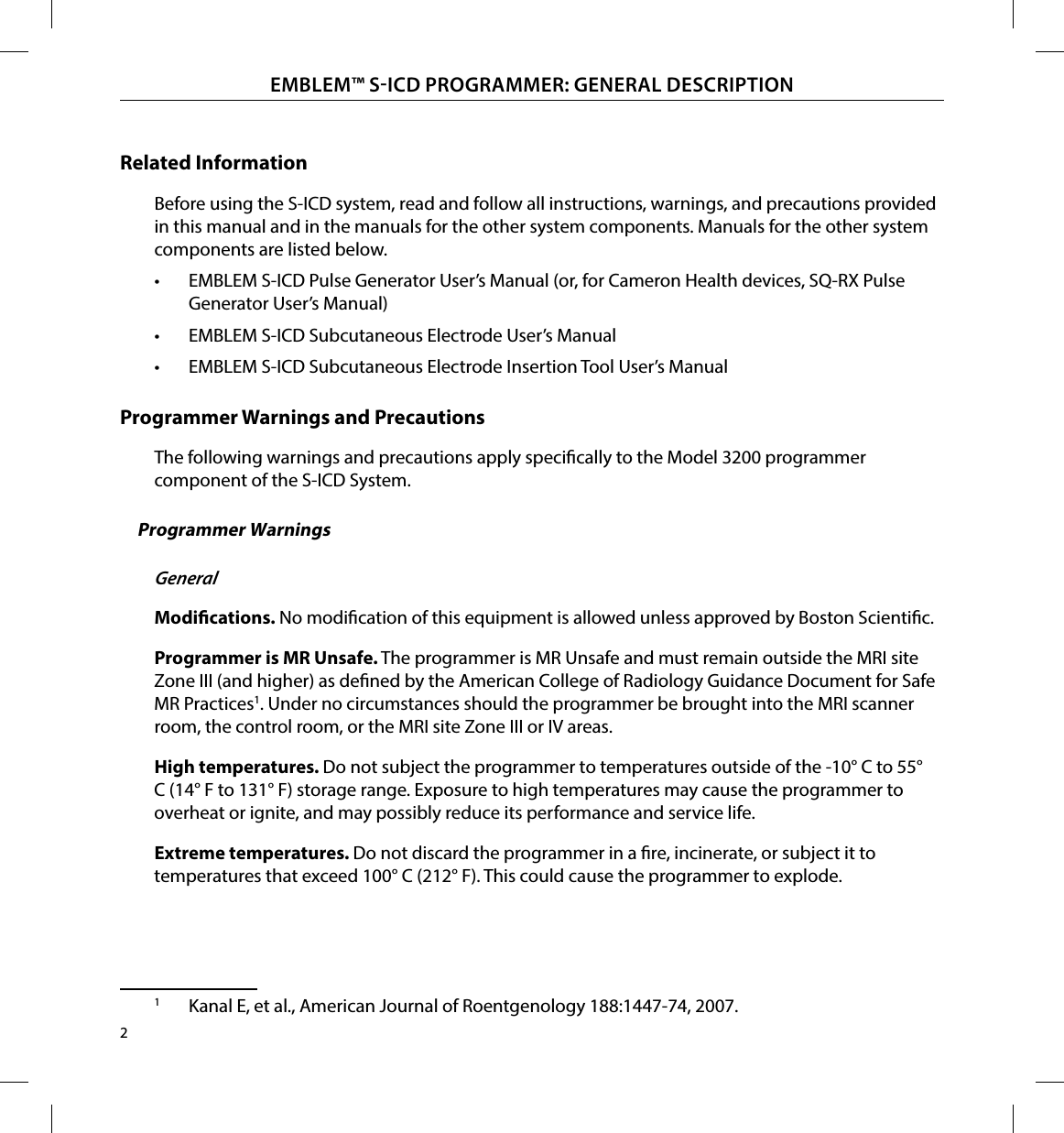
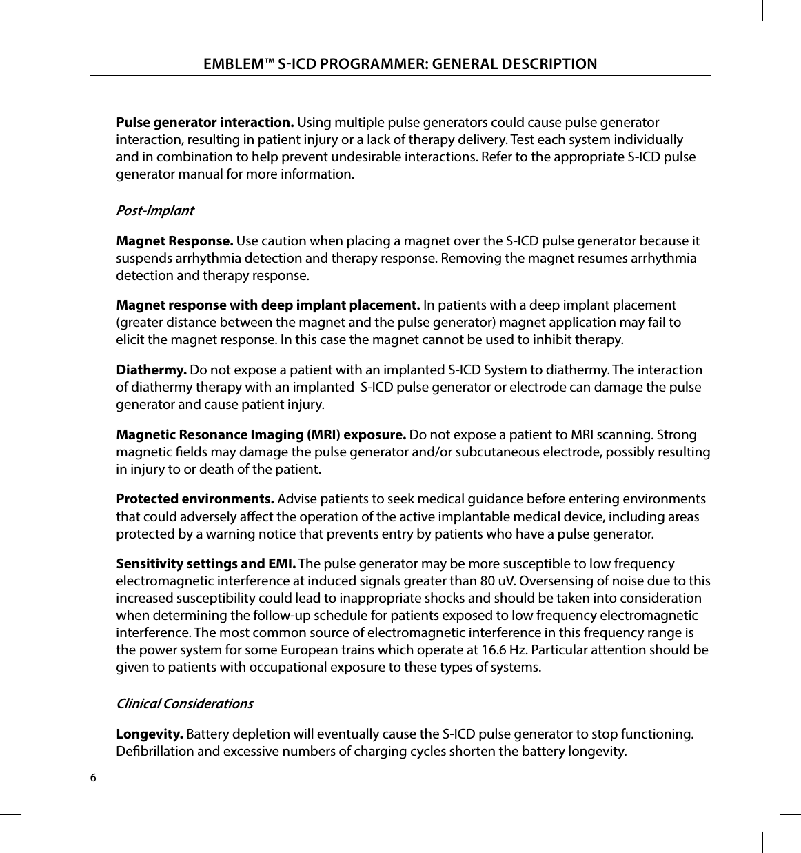
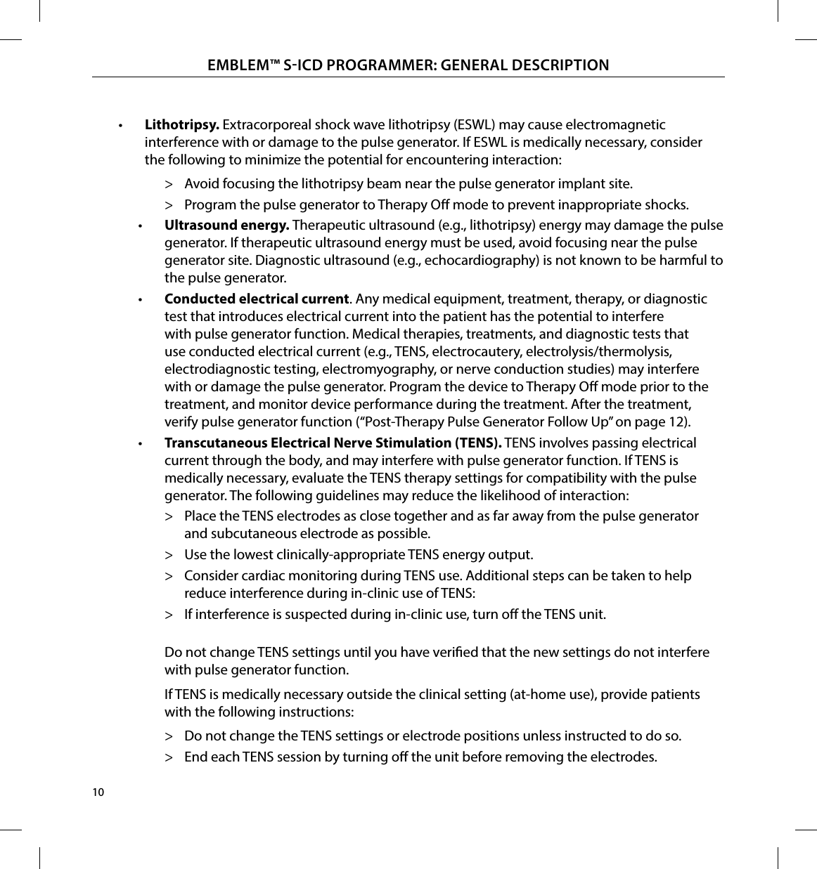
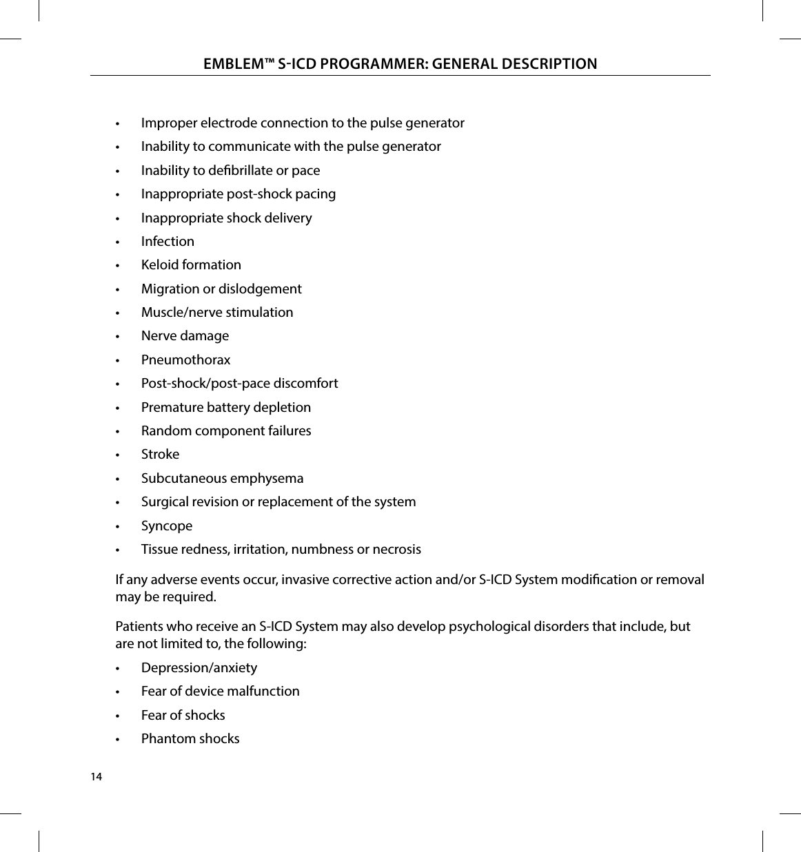
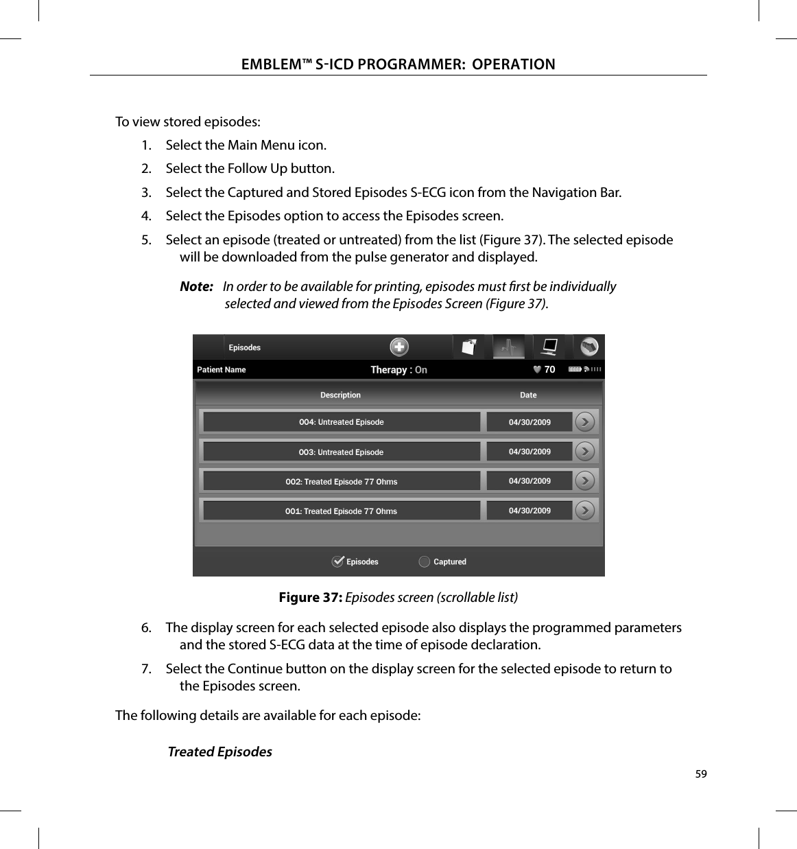
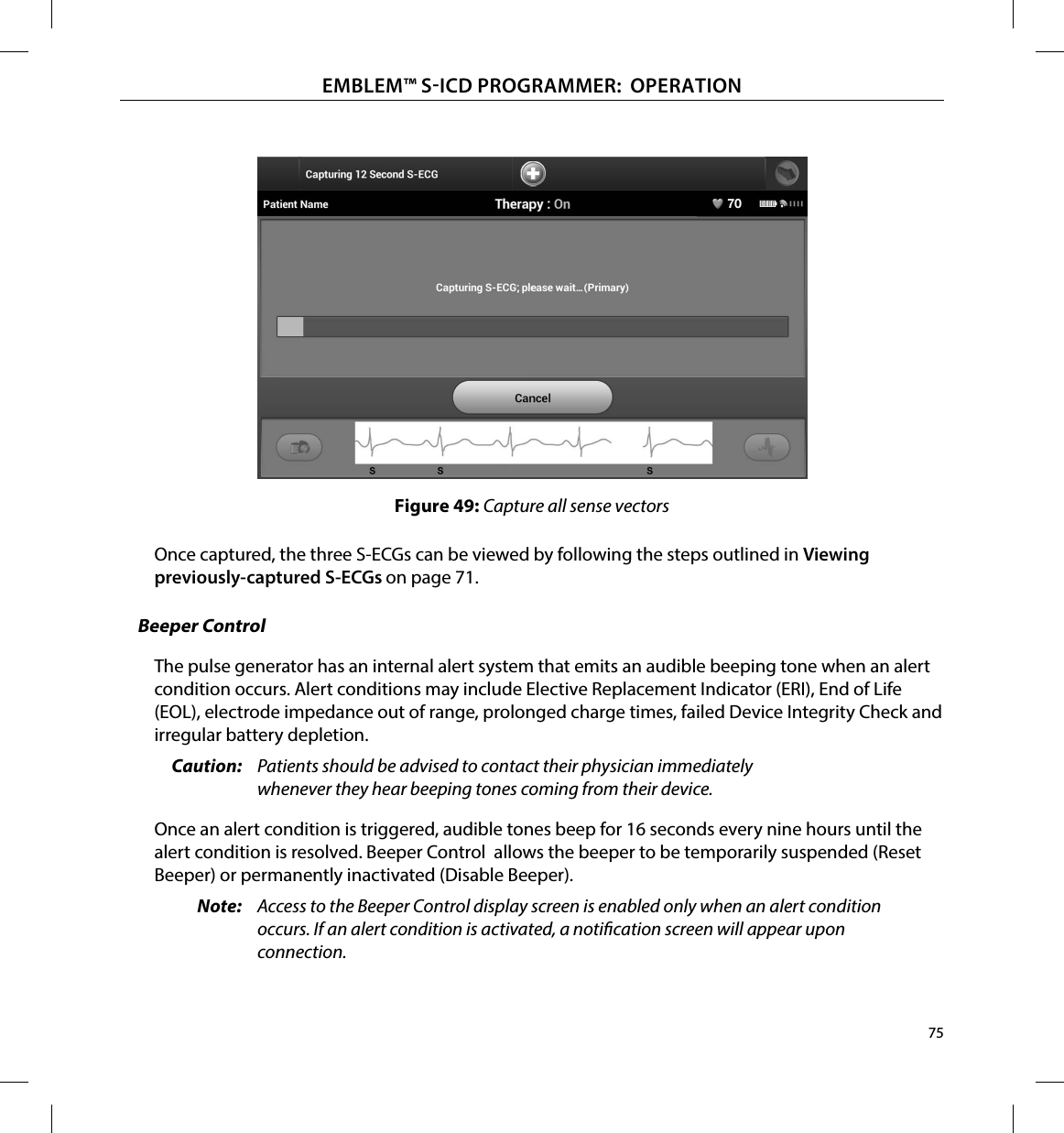
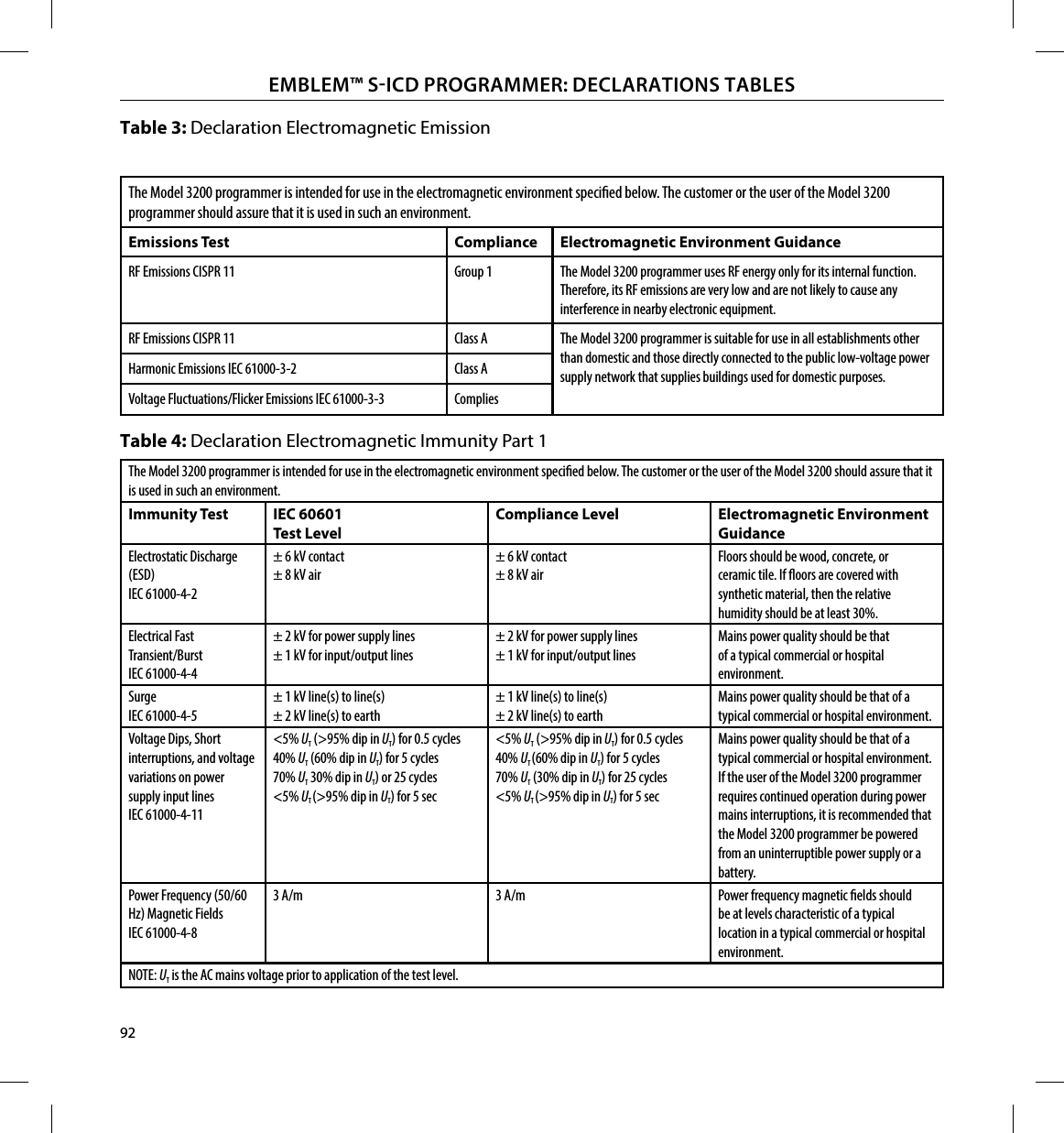
![94EMBLEM™ SICD PROGRAMMER: DECLARATIONS TABLESTable 6: Recommended Separation DistancesRecommended separation distances between portable and mobile RF communications equipment and the Model 3200 programmerThe programmer is intended for use in an electromagnetic environment in which radiated RF disturbances are controlled. The customer or the user of the programmer can help prevent electromagnetic interference by maintaining a minimum distance between portable and mobile RF communications equipment (transmitters) and the programmer as recommended below, according to the maximum output power of the communications equipment.Rated maximum output power of transmitter WSeparation distance according to frequency of transmitter m150 KHz to 80 MHz 3.5V1√ Pd = []80 MHz to 800 MHz 3.5E1√ Pd = []800 MHz to 2.5 GHz 7E1√ Pd = []0.01 0.117 0.117 0.2330.1 0.369 0.369 0.7381 1.17 1.17 2.3410 3.69 3.69 7.38100 11.7 11.7 23.3For transmitters rated at a maximum output power not listed above, the recommended separation distance d in metres (m) can be estimated using theequation applicable to the frequency of the transmitter, where p is the maximum output power rating of the transmitter in watts (W) according to thetransmitter manufacturer.Note 1: At 80 MHz and 800 MHz, the separation distance for the higher frequency range applies.Note 2: These guidelines may not apply in all situations. Electromagnetic propagation is aected by absorption and reection from structures, objects and people.Table 7: EMI/RFI Information: Programmer-to-Pulse Generator CommunicationSpecication Medical Implant Communications Service (MICS)Frequency band 402-405 MHzModulation type FSKRadiated Power <25 μWBandwidth < 300 KHzTable 8: EMI/RFI Information: Bluetooth® Wireless Printing and Data TransferSpecication Bluetooth® 4.0 wireless technologyFrequency band 2.402-2.480 GHzModulation type GFSK, π/4-DQPSK, 8DPSKRadiated power <100 mWBandwidth < 1 MHz](https://usermanual.wiki/Boston-Scientific/CRM320014/User-Guide-2422872-Page-100.png)