Bradfordwhite Canada Commercial Gas Natural Flue Damper Electronic Ignition D Servicemanual 47985 Bwc_manual User Manual
Bradford-White-Corp-D-38T-155-Users-Manual-484782 bradford-white-corp-d-38t-155-users-manual-484782
Commercial Gas Natural Flue Damper Electronic Ignition D Servicemanual 47985 commercial_gas_natural_flue_damper_electronic_ignition_d_servicemanual_47985 commercial_gas_natural_flue_damper_electronic_ignition_d_servicemanual_47985 uploads wp-content bradfordwhitecorp :
D-38T-155 to the manual e80fee06-1e39-47d8-9084-fa248f360847
2017-01-09
User Manual: Bradfordwhite Canada Commercial Gas Natural Flue Damper Electronic Ignition D Servicemanual 47985 canada_commercial_gas_natural_flue_damper_electronic_ignition_d_servicemanual_47985 uploads wp-content bradfordwhitecorp :
Open the PDF directly: View PDF ![]() .
.
Page Count: 44
Save this manual for future reference
Manual 47985A
SERVICE
MANUAL
Troubleshooting Guide
and Instructions for Service
(To be performed ONLY by
qualified service providers)
Models Covered
by This Manual:
For The Bradford White
“D” Series Models:
D38T155
D75T(125,160,300)
D65T(370,399)
D80T(180,199,250)
D80T(425,505)
D100T(199,250)
D80L(399,450,505)
D100L(199,250,270,300)
D100S(199,250)
Gas Water Heaters
COMMERCIAL 24 VOLT FLUE DAMPER
SERIES WATER HEATER WITH HONEYWELL
INTEGRATED CONTROL SYSTEM
®

Table of Contents
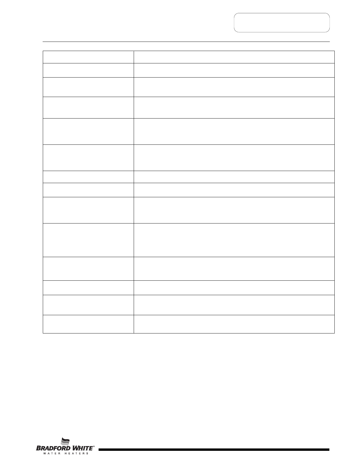
Page Service Procedure
Introduction 4 - - -
Tools Required for Service 4 - - -
Sequence of Operation 6 - - -
Troubleshooting 7 - - -
Thermostat Circuit Testing 24 D24-I
Pilot Operation Testing 27 D24-II
Main Burner Operation Testing 30 D24-III
Main Burner & Pilot Removal & Inspection 32 D24-IV
Flue Baffle Removal & Inspection 35 D24-V
Anode Removal & Inspection 36 D24-VI
Generic Parts List 38 - - -
Glossary of Terms 41 - - -
Notes 41 - - -
Page 2
2

FEATURES OF HONEYWELL INTEGRATED CONTROLS SYSTEM
Attractive digital water heater display on control panel for setting and displaying
the temperature setpoint. Pressing temperature up and down buttons changes
the temperature setpoint. Temperature format may be displayed in degrees F or
degrees C.
Single control board with plug in wiring controls temperature, ignition, and flue
damper operation.
Reduced number of parts for servicing and wiring.
Plug in wiring reduces chance of miswiring.
Water heater display will show diagnostic codes in the event the water heater
needs servicing. Aids in diagnosing and servicing the water heater.
Water heater display can show up to 10 previous error codes in the service mode
to further aid in servicing the water heater.
Page 3
3

Tools Required for Service
It is intended for this manual to be used by qualified service personnel for the primary purpose of
troubleshooting analysis and repair of the Bradford White 24 Volt Flue Damper Series Water
Heater. Understanding the sequence of operation section of this manual will contribute greatly to
troubleshooting this product.
Troubleshooting begins by noting the error code, if any, on the water heater control display and
finding the section in this service manual for diagnosing the problem for this error code. This step
by step procedure beginning on page 5 will direct the service provider to a series of test
procedures to determine root cause of failure.
Contact Technical support immediately if diagnosis is not determined using the methods described
in this service manual.
Page 4
Manometer: Two types available, a liquid “U” tube type or a digital (magna-helic)
type. This device is used to measure gas and/or air pressures and
vacuum.
Multi-Meter: A digital type is strongly recommended. This device is used to measure
electrical values. The meter you select must have the capability to
measure volts AC, volts DC, Amps, micro-amps and ohms.
Thermometer: Used to measure water temperature. An accurate thermometer is
recommended.
Water Pressure Gage: Used to measure water supply pressure. Also used to determine tank
pressure by adapting to the drain valve of the heater.
Jumper Leads: A length of wire (12" min.) with alligator clip at both ends.
Various Hand Tools: Pipe wrench, channel locks, open end wrench set, 12" crescent wrench,
Allen wrench set, torx bit set, screw drivers (common & phillips), long
reach (12") magnetic tip phillips head screw driver #2 tip, ¼" nut driver,
pliers (common & needle nose), socket set including a 1-1/16 deep well
socket, wire cutters, wire strippers, wire crimpers, torpedo level, small
shop vac, step ladder, and flashlight.
Introduction
4
Power Supply Dedicated 120 VAC, 60 Hz., 15 A
Current Draw Less than 5 Amps.
Approved Gas Type Natural or Propane. Gas supply must match the gas type listed on the water
heater rating label.
Gas Supply Connection 1" NPT connection to gas valve for 370,000 Btu/hr. and over for natural gas,
¾" NPT for rest. Schedule 40 black iron pipe recommended.
Gas Pressure (Nat. & L.P.) Manifold Pressure: 4.5" w.c. natural gas, 10.0" w.c. L.P. Gas Supply
Pressure: At least 1" above manifold pressure with water heater operating,
14" w.c. maximum.
Venting System Atmospherically Vented, Type B venting system or approved chimney. Follow
current National Fuel Gas Code requirements or in Canada, the Natural Gas
and Propane Installation Code.
Minimum Clearance for Servicing 24" Front Clearance, 20" Top, 6" Sides.
Maximum Water Supply Pressure 150 PSI.
Thermostat Sensor(s) Redundant thermister with 11,900 + or - 0.5% ohms resistance at 70 deg. F.
Sensor inside well for lower sensor. Some models use an additional upper
sensor (w/o well) with same resistance values.
Control Board Honeywell Integrated Control Board for Temperature Control, Flue Damper,
and Ignition Control Functions. Operates on 24 volts AC current from
transformer. Some models use single sensor boards, others use two
sensors.
Control Display Honeywell LCD Control Display with Temperature Setpoint, Format, and Error
Code Display in User Mode, Diagnostic Functions in Service Mode.
Communicates with Control Board.
Transformer 120 VAC Primary, 24 VAC Secondary, 40 VA.
Pilot Intermittent Pilot with Spark Electrode and Flame Sensor monitored by Control
Board.
Flue Damper 24 VAC, 60 Hz., 80 Ma.
Page 5
Specifications
5
1
Thermostat calls for heat.
The control board sends 24 volts from damper terminal #2 on the control plug
to the flue damper.
2Flue damper begins to rotate open. Once the flue damper is fully open, the damper end switch closes and 24 volts
is allowed to continue through damper to damper pin terminal #5.
3
4Once pilot flame is proven, sparking will stop.
Page 6
Sequence of Operation
Trial for ignition (three 90 second ignition trials, with 65 second pauses
between trials).
Control Board simultaneously sends:
1. 24 volts from control pin terminal #8, to “MV/PV”
terminal of gas valve (common terminal).
2. 24 volts from control pin terminal #2, to “PV”
terminal of gas valve to establish
gas flow at pilot.
3. Low current high voltage from “spark”
terminal, to generate spark at the pilot and
ignite pilot gas flow.
4. Pilot flame proving signal (measured in
micro-amps). from the “sense” terminal, to
prove pilot flame.
5Once sparking stops, 24 volts is sent from control pin
terminal #5 on control board, to “MV” terminal on gas valve
to establish main burner gas flow. Main burners ignite from
the pilot flame.
The control board constantly monitors pilot flame through
the flame sensor rod. If pilot flame is lost, pilot and main
burners are shut down. After a 65 second inter-purge
period, the control will attempt to re-light the pilot beginning
at sequence 3 above.
7Main burner fires until the thermostat is satisfied. The control
board interrupts 24 volts through the damper and the gas valve
circuit. Pilot and main burners are turned off.
8Flue damper rotates to the closed position.
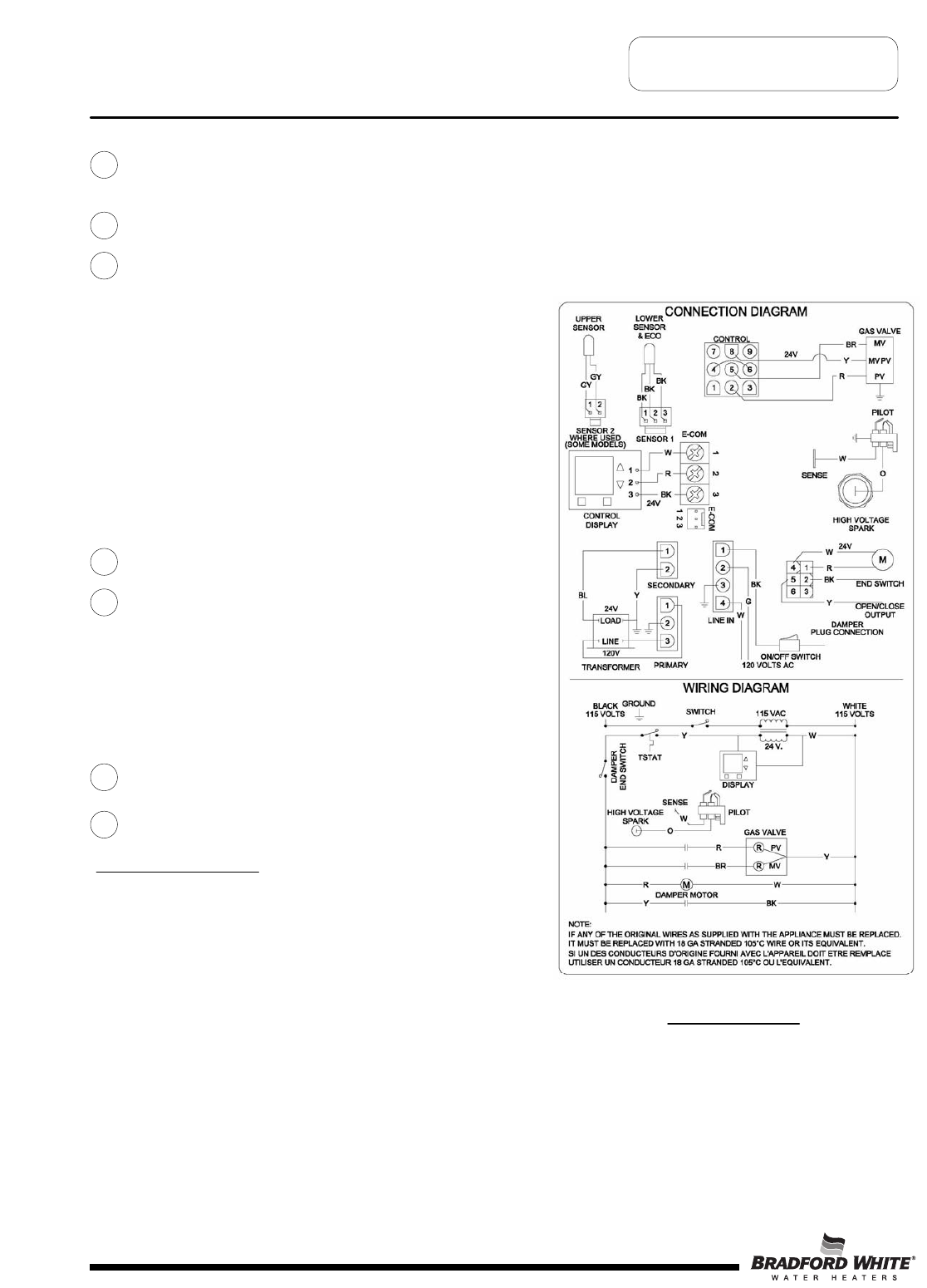
WIRING DIAGRAM
LOCKOUT CONDITION
Control board will go into “Soft Lockout” if the pilot cannot be lit
after 3 ignition trials. The water heater display indicates a lockout
condition by showing an error code number (62 or 63) with
“Service Needed” in the display window. Refer to error codes in
the diagnostic section of this Service Manual. In a “Soft Lockout”
condition, the control will wait for 60 minutes and then make 3
more attempts to light the pilot and establish the main burners.
Soft lockout reset is accomplished by depressing the lower right
button under “Reset” for 3 seconds.
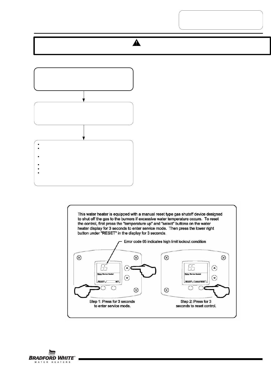
If the water heater should reach 200 degrees F, then the high limit
control will shut off the burners and the water heater will go into a
“Hard Lockout”. Error code 65 will be shown in the water heater
display. The control can only be reset in the “service mode”,
which is detailed in the next section of this Service Manual.
6
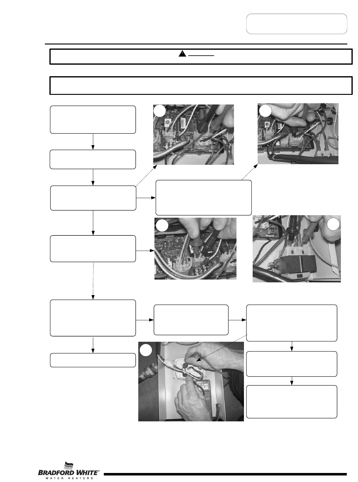
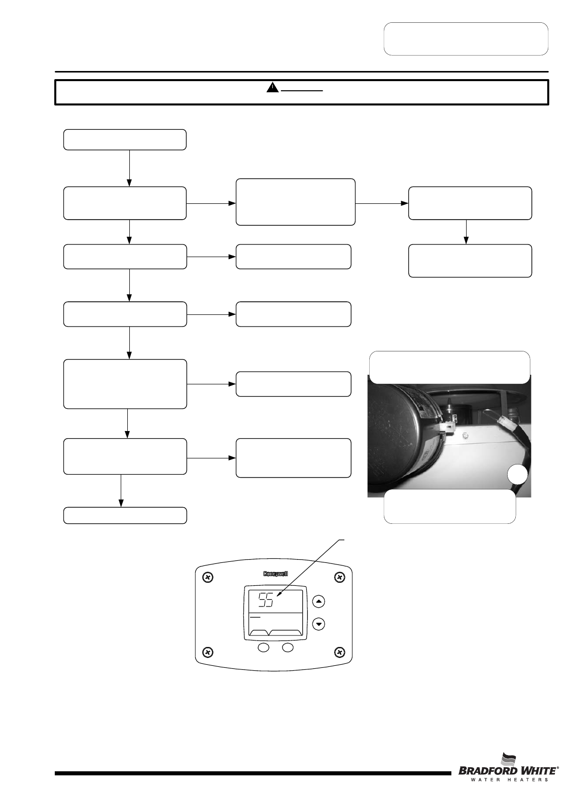
CAUTION
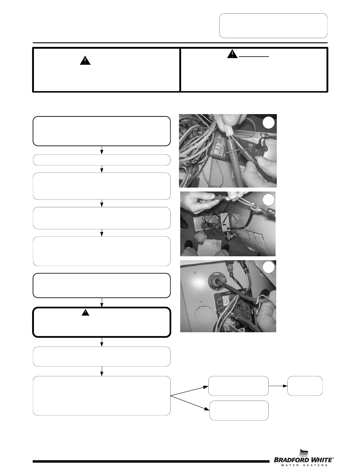
Use Caution Not to Damage Connectors when making Voltage Measurements or Jumping Terminals
Water Heater Fault: Water heater does not operate
Display Error Code: Water heater display does not operate - blank display
Check main power supply to water
heater - fuse, circuit breaker, plug
receptacle, line cord or wiring to
water heater.
Check to make sure switch on top of
control panel is in the ON position
Verify Primary and Secondary
voltage at the control board.
Voltage at primary pins 1&3 (white and
black wires) should be 110-120. If not,
check Line In pins 1&4. Check line cord
with ohmeter. Replace line cord if
defective.
If there is not 24 volts at Secondary
pins on the control board, check
transformer. Replace transformer
or wire harness.
Does water heater display operate?
Does damper begin to open?
Increase thermostat setting if tank is
warm and make sure the control
display status reads “Heating”.
Check wire connections of
board to display. See
illustration.
With the control cover tilted down,
measure the voltage between red and
black wire pin connections to display.
Voltage should be 24 volts AC
measured at the back of the Control
Display.
If no voltage at Display, check wire
harnesses and voltage at E-com
screw terminals (see photo 5).
Replace display if voltage is present at
display pin terminals. Replace control
board if no voltage is present at E-
com terminals (1&3, white-black wires
and 1&2, white-red wires) to display.
N
Y
See next page
Checking primary voltage to
transformer from board. Pins to
black and white wires.
Checking line voltage to board.
Pins to black and white wires.
Checking secondary voltage from
transformer. Pins to blue and yellow
wires.
Checking transformer voltage, front
terminals are 24 volts, rear terminals
are 120 volts.
Page 7
Troubleshooting
1 2
34
5
7
Does damper blade move to the full
open position?
Error code #55 on display.
Remove damper from heater and
jump black & yellow wires of
heater harness. Refer to photo on
this page.
Does water heater begin to
operate?
Check for debris limiting damper
rotation. If no debris, replace
damper.
Isthere pilot flame? Error code #62 on display. See
“Pilot Will Not Light”.
Does Main Burner operate? Error code #62 on display. See
“Pilot Lights, No Flame Signal”
Does burner continue until
thermostat set point is reached?
See setting display in Service Mode
and displaying temperature
sensors.
Error code #63 on display. See
“Main Burner Short Cycles”.
Does the flue damper rotate to the
fully closed position?
Error code #56 on display.
Check for debris limiting damper
rotation. If no debris, replace
damper
System okay
Damper vane show in open position. If damper
is closed, disconnect from harness and
REMOVE damper from water heater.
Harness shown disconnected from
damper with BLACK and YELLOW
wires jumped.
CAUTION
Use Caution Not to Damage Connectors when making Voltage Measurements or Jumping Terminals
N
YY
N
N
N
N
Y
Y
Y
Y
From previous page
Example of error code shown on control display.
Page 8
SELECT Lockout RESET
Status Service Neede d
Error Code Shown
in Water Heater Display
Troubleshooting
6
8
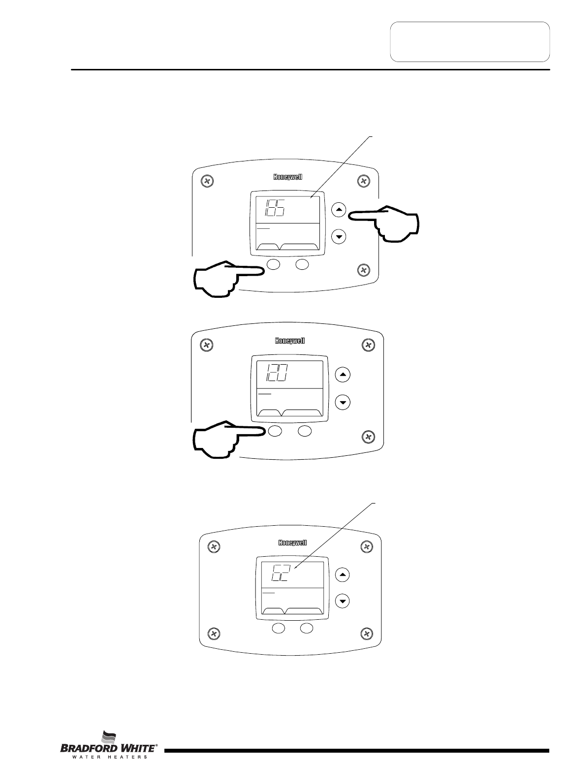
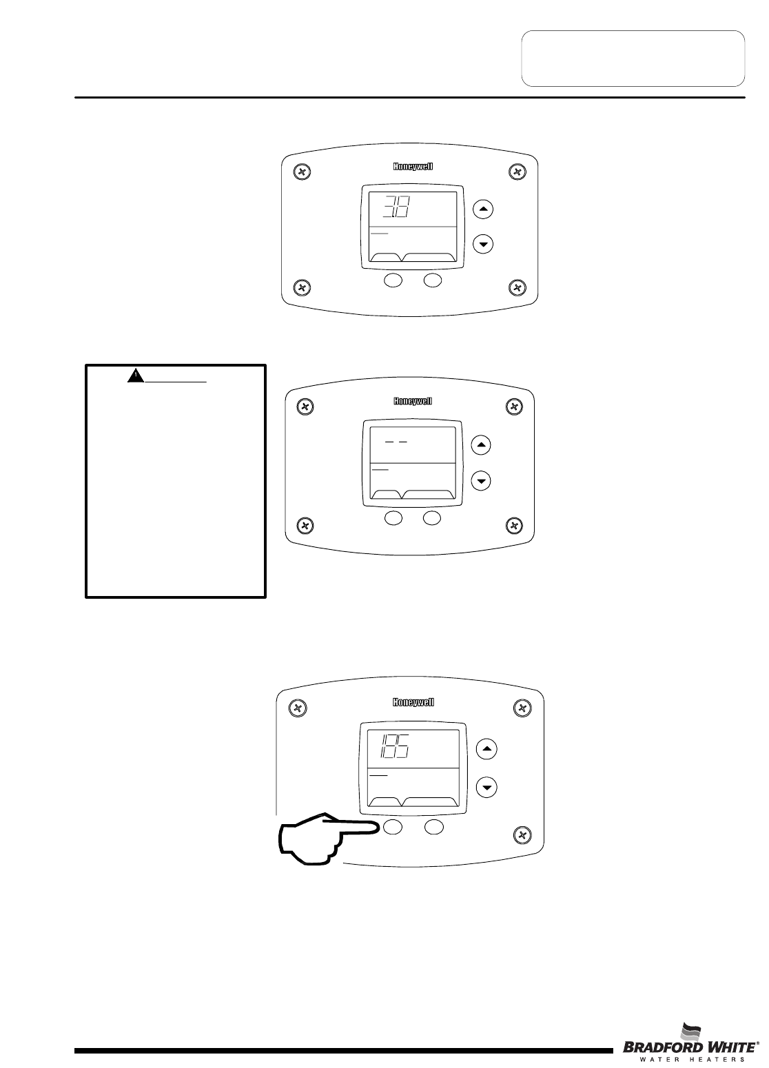
ACCESSING SERVICE MODE ON THE WATER HEATER DISPLAY (FOR SERVICE PERSONNEL ONLY)
The display has a “service mode” for changing the maximum setpoint and accessing information in aiding servicing of the
water heater. This procedure is for service and installation personnel only. To enter the Service Mode, follow the steps
illustrated below:
Step 1: Press “Select” and “Temperature Up” buttons together and hold for 3 seconds until “Max Setpoint” is shown in the
display.
Step 2: Pressing “Select” button will change display to next mode
SELECT SET
Status
°F
idl
e
Operational
Wate
r
Temp
The following is the sequence of modes available in “Service Mode” by pressing the “Select” button:
Error Code Number (Display/Reset). This is only shown if there is an operating error in the “User Mode”.
"Max Setpoint”
SELECT SET
Statu
s
idle
Operational
next to Temperature
Setpoint value.
Max
Setpoint
SELECT Lockout RESET
Status Service Needed
Error Code Shown
in Water Heater Display
Page 9
Troubleshooting
Using Control Display for Servicing the
Water Heater
9
1. Max Setpoint (Display/Change)
2a. Water Temperature Average (Displays average if there are two sensors - sensor temperature displayed if single
sensor is used).
SELECT SET
Status
°F
idle
Water Temp
Operational
2b. Water Temperature - Upper Sensor (Displays if there is an upper sensor - some models)
SELECT SET
Status
°F
idl
e
Operational
Upper Sensor
2c. Water Temperature - Lower Sensor (Displays if there are two sensors)
SELECT SET
Status
°F
idle
Operational
Lower Sensor
SELECT SET
Status
°F
idl
e
Operational
Max Setpoint value in
Water Heater Display
Max
Setpoin
t
&
Page 10
Troubleshooting
10
3. Flame Current of Pilot Flame Sensor (Displays only in the Heating Cycle)
SELECT SET
Status
Heating
Operational
Flame Current
ȝA
4. Setpoint (Display/Change)
SELECT SET
Status
°F
idle
setpoint
Operational
5. °F/°C (Display/Change)
SELECT SET
Status
°F/C°
idle
Operational
°Fsetpoint
6. Differential (Display only - shows the differential of the thermostat)
SELECT SET
Status
°F
idl
e
Differential
Operational
Page 11
Troubleshooting
11
7. Software Version (Display only)
SELECT SET
Status
idle
Operational
Soft
8. Error Code History (Displays if there are present error codes or up to 10 previous error codes). Water Heater Display
will show a “--“ if there are no error codes.
SELECT SET
Status
idle
Operational
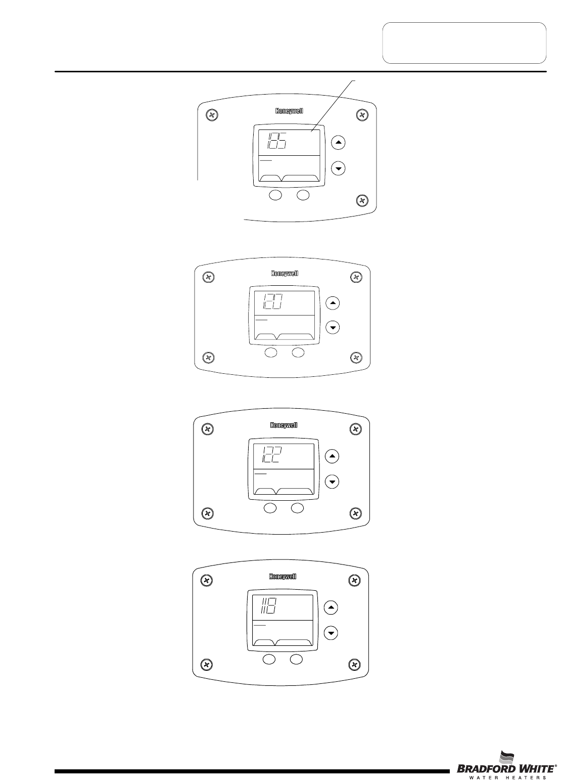
To change the Maximum Setpoint Limit (Max Setpoint) for the temperature setpoint:
Step 1: In service mode press the “Select” button until “Max Setpoint” is displayed.
SELECT SET
Status
°F
idle
Max
Operational
Setpoint
Page 12
Troubleshooting
WARNING
Setting the water temperature
to the maximum set point can
result in scalding hot water
delivered to the faucets. It is
highly recommended that the
maximum setpoint be adjusted
to the lowest temperature
possible for the needs of the
installation. Make sure the
water heater control display is
not in a public area that can
result in the temperature
settings being improperly
adjusted.
12
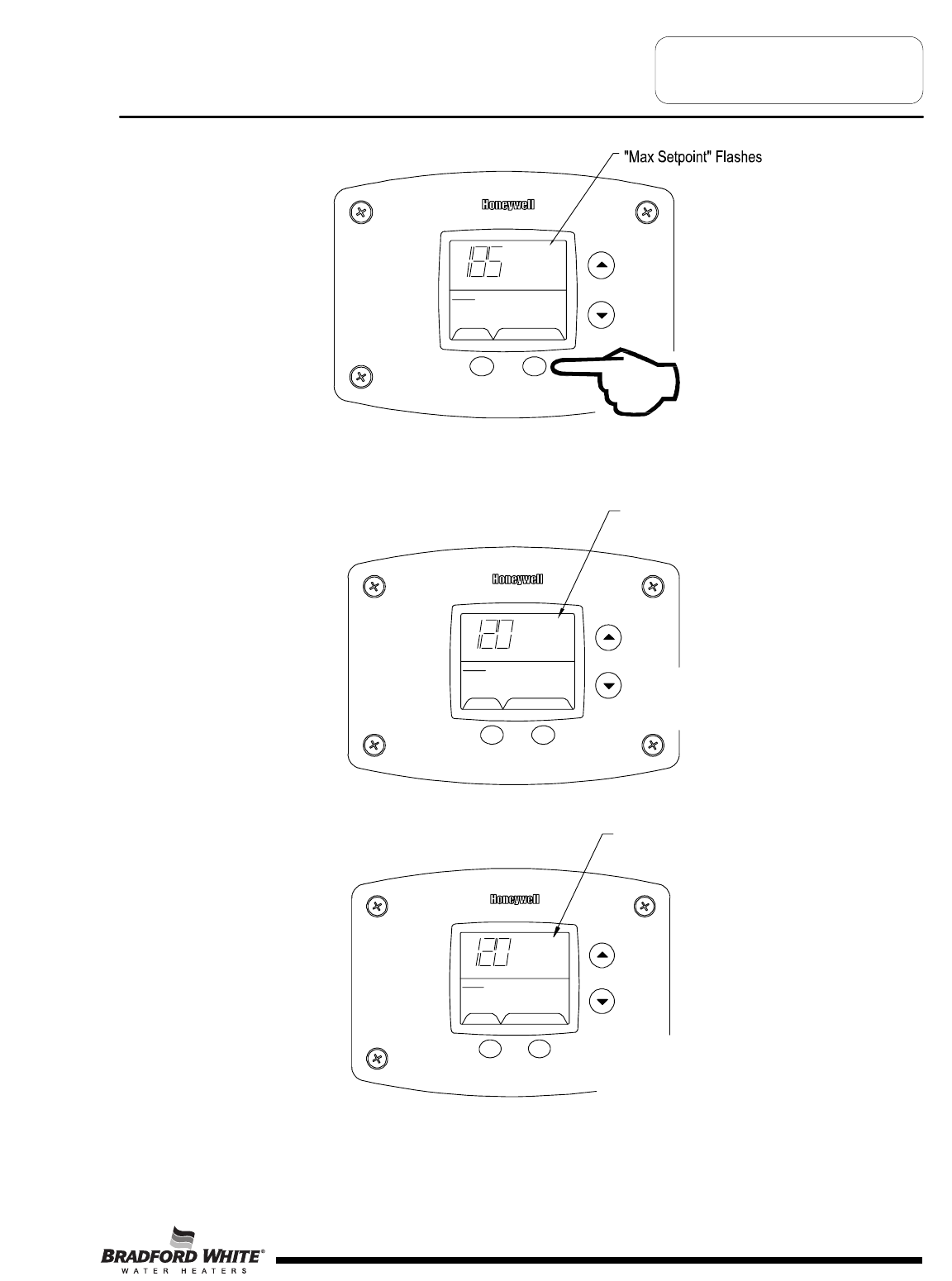
Step 2: Press “Set” button to enter setting mode. “Max Setpoint” will flash to indicate setting mode.
SELECT SET
Status
°F
idle
Operational
Max
Setpoint
Step 3: Press the “UP” or “DOWN” buttons to change the maximum setpoint value. This will limit the maximum setpoint
the user can select. Note: The maximum setpoint is approximately 180°F.
Step 4: Press “Set” button to confirm new “Max Setpoint” value and stop setting mode.
Page 13
"Max Setpoint" stops flashing
SELECT SET
Status
°F
idle
Ope
r
ational
Max
Setpoin
t
%
SELECT SET
Status
°F
idle
Operational
Max
Setpoint
%
"Max Setpoint" continues to flash
while making adjustments
Troubleshooting
13
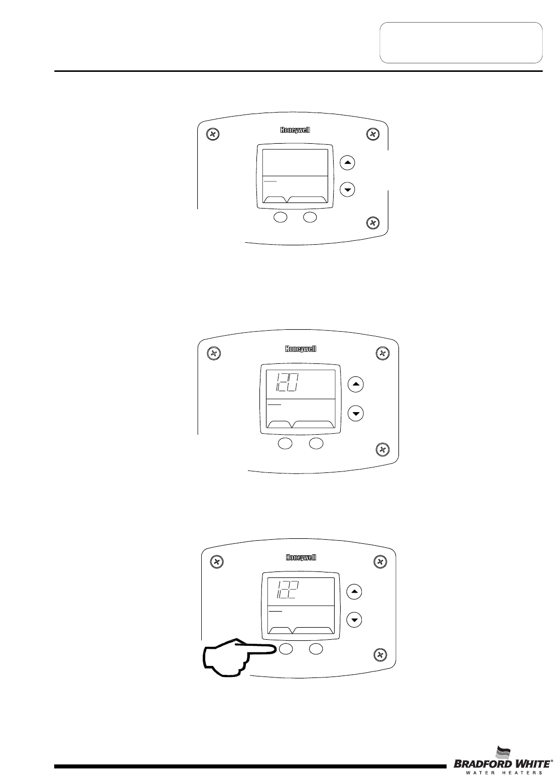
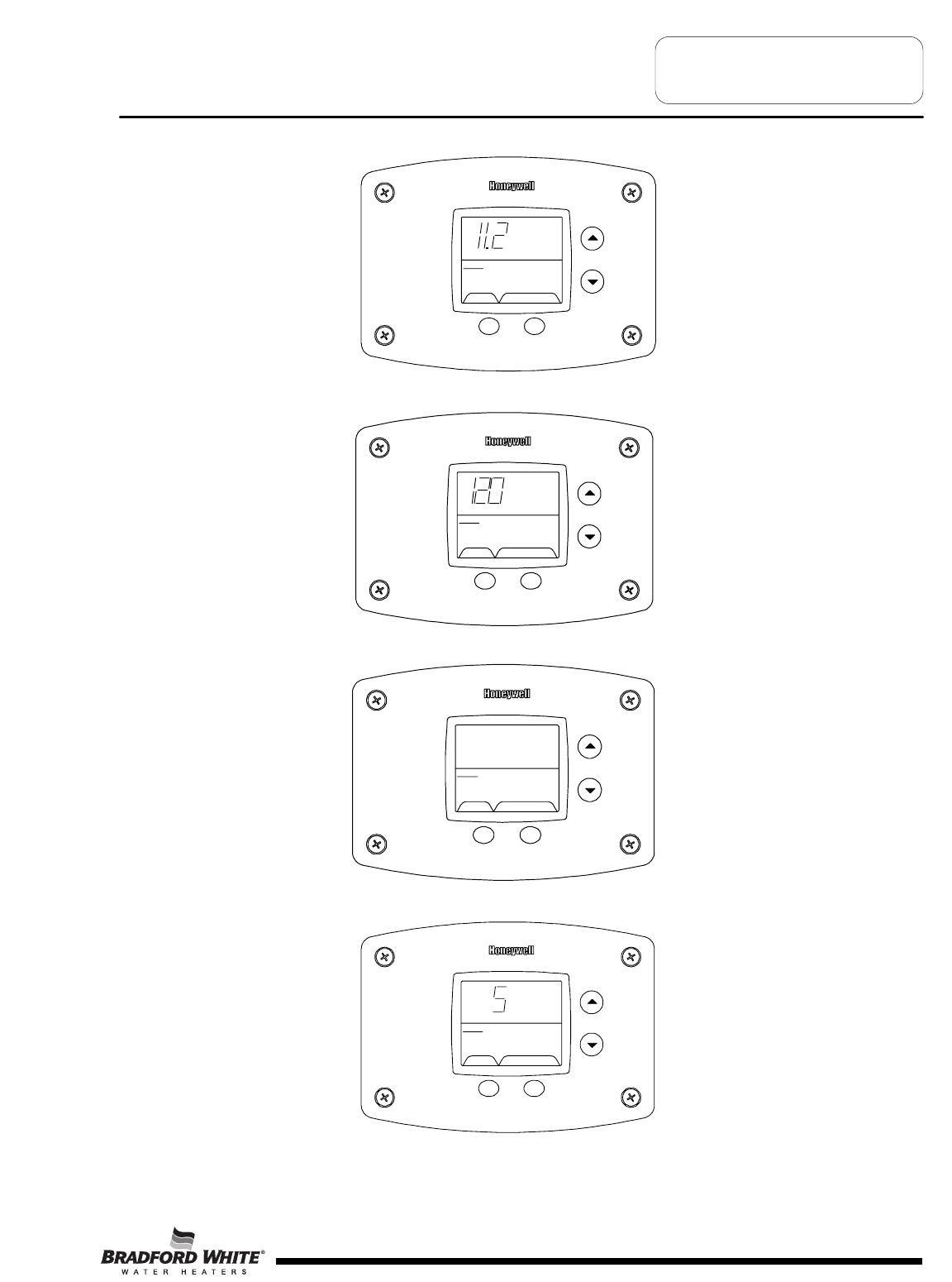
Step 5: 30 Seconds after the last button press, the Water Heater Display will go back to “User Mode”. It will read “Max
Setpoint” without showing a temperature value if the temperature setpoint is at the maximum setting. The Water
Heater Display can be set back to the “User Mode” immediately by pressing both the “Temperature Up” and “Select”
buttons together for 3 seconds.
SELECT SET
Status
idle
Operational
Max
Setpoint
%
&
Exiting Service Mode
Display of Water Temperature:
Step 1: In Service Mode, Press the “Select” button until “Water Temp” is displayed in the upper right section of the
water heater display. For water heaters using two temperature sensors in the tank, this will be the average reading
between the two sensors. For water heaters using a single sensor, this is the reading for the sensor.
Step 2: For water heaters using two temperature sensors, pressing the “Select” button again displays the Upper
Sensor temperature reading. “Upper Sensor” will be displayed in the lower right side of the status window of the
water heater display.
SELECT SET
Status
°F
idl
e
Operational
Upper Sensor
Page 14
Troubleshooting
SELECT SET
Status
°F
idle
Operational
Water
Temp
&
14
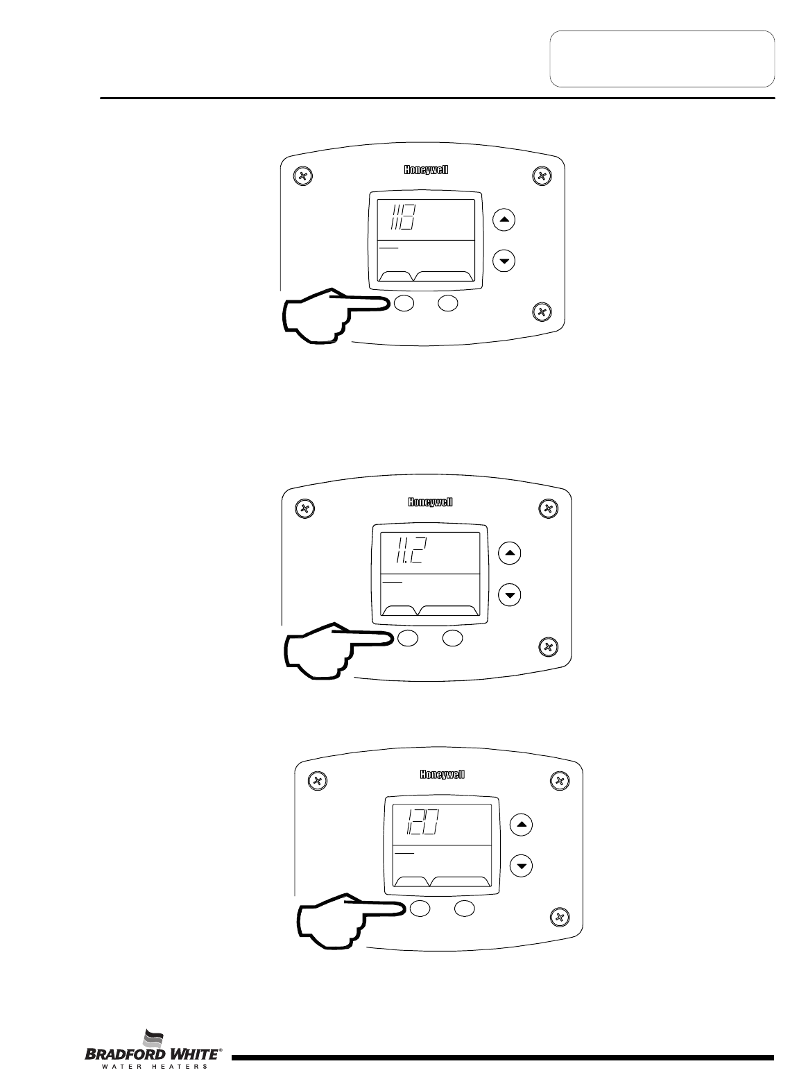
Step 3: For water heaters using two temperature sensors, pressing the “Select” button again displays the Lower Sensor
temperature reading. “Lower Sensor” will be displayed in the lower left side of the status window of the water heater
display.
SELECT SET
Status
°F
idle
Operational
Lower Sensor
To Display Flame Sense Current of the Pilot Flame Sensor:
The pilot flame sense current is available only when the burners are in operation. Step 1: Make sure the status displays
“Heating” or draw enough hot water to start the burners. Step 2: Enter the “Service Mode” described previously. Step 3:
Press the “Select” button until a number value is displayed with “Flame Current” to the right of the number. The value
displayed is in microamps (ȝA).
SELECT SET
Status Operational
Flame
Current
Heating
ȝA
To Display and Change Temperature Setpoint:
Step 1: In “Service Mode” press the “Select” button until “Setpoint” is shown in the water heater display
SELECT SET
Status
°F
idle
setpoint
Operational
Page 15
Troubleshooting
15
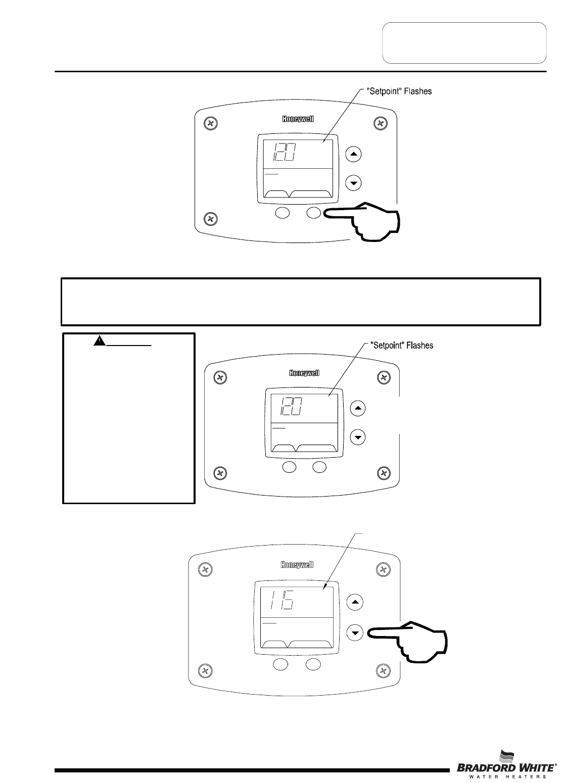
Step 2: Press the “Set” button to enter the setting mode. “Setpoint” will flash in the water heater display.
SELECT SET
Status
°F
idle
setpoint
Operational
Step 3: To raise the temperature setpoint, press the “Temperature Up” button until the desired temperature is shown on
the water heater display.
SELECT SET
Status
°F
idle
setpoint
Operational
%
Step 4: To lower the temperature setpoint, press the “Temperature Down” button until the desired temperature is shown
on the water heater display.
Page 16
SELEC
T
SE
T
Status
°F
idle
setpoint
Operational
"Setpoint" Flashes
Troubleshooting
WARNING
Setting the water temperature
to the maximum set point can
result in scalding hot water
delivered to the faucets. It is
highly recommended that the
maximum setpoint be adjusted
to the lowest temperature
possible for the needs of the
installation. Make sure the
water heater control display is
not in a public area that can
result in the temperature
settings being improperly
adjusted.
NOTICE
The maximum temperature that can be set in the Water Heater Display is limited to the “Max Setpoint” described
previously. To change the “Max Setpoint”, refer to the procedure “To Change the Maximum Setpoint Limit…"
described previously under “Accessing the Service Mode on the Water Heater Display”.
16
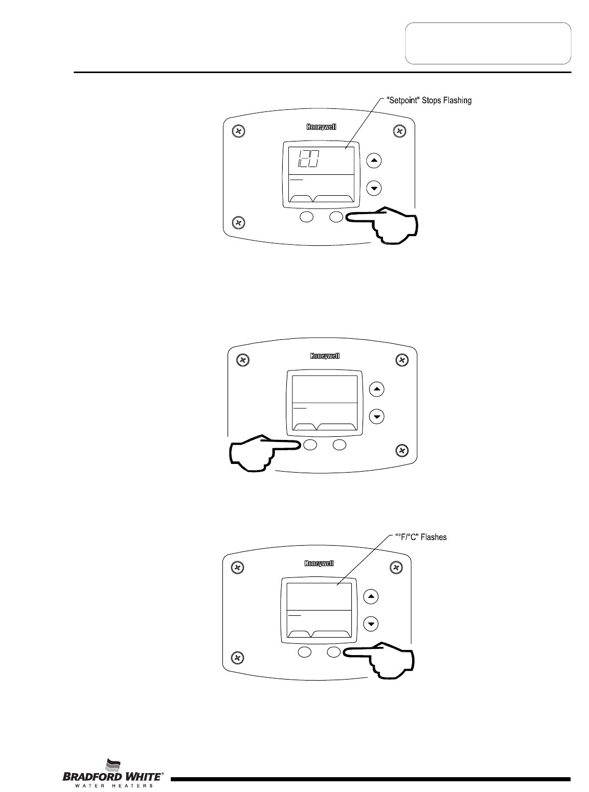
Step 5: When the desired setpoint is reached on the water heater display, press the “Set” button to confirm the new
setpoint. “Setpoint” stops flashing in the water heater display.
SELECT SET
Status
°F
idle
setpoint
Operational
To Display and Change Temperature Format (°F/°C):
To Change Temperature Format in Display from °F to °C or °C to °F:
Step 1: While in “Service Mode”, press “Select” button until “°F/°C” is shown in the upper right portion of the water heater
display.
SELECT SET
Status
idle
Operational
°F °F/C°
Step 2: Press “Set” button to change temperature format. “°F/°C” symbol will flash in the water heater display.
SELECT SET
Status
idle
Operational
°F °F/C°
Page 17
Troubleshooting
17
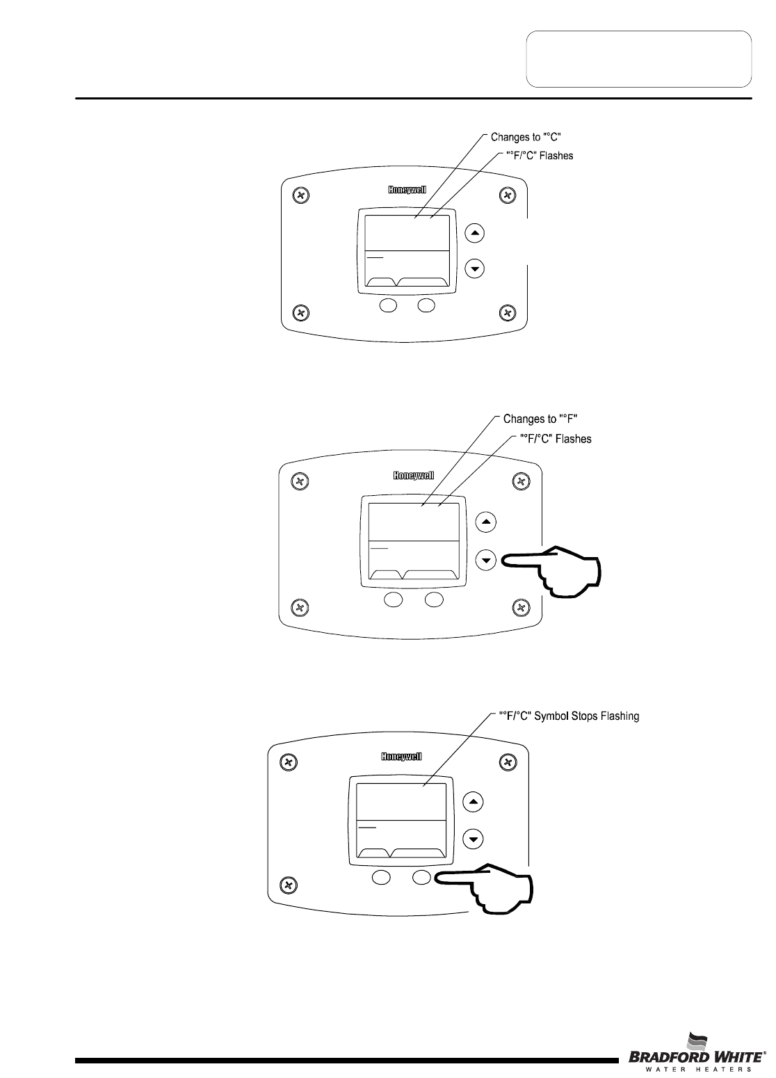
Step 3a: Press “Temperature Up” button to change temperature format to °C
SELECT SET
Status
idle
Operational
°C
%
°F/C°
Step 3b: Press “Temperature Down” button to change temperature format to °F
SELECT SET
Status
idle
Operational
°F °F/C°
Step 4: Press “Set” button to confirm °F or °C format. °F/°C will stop flashing
SELECT SET
Status
°F
idle
Operational
°F °F/C°
Page 18
Troubleshooting
18
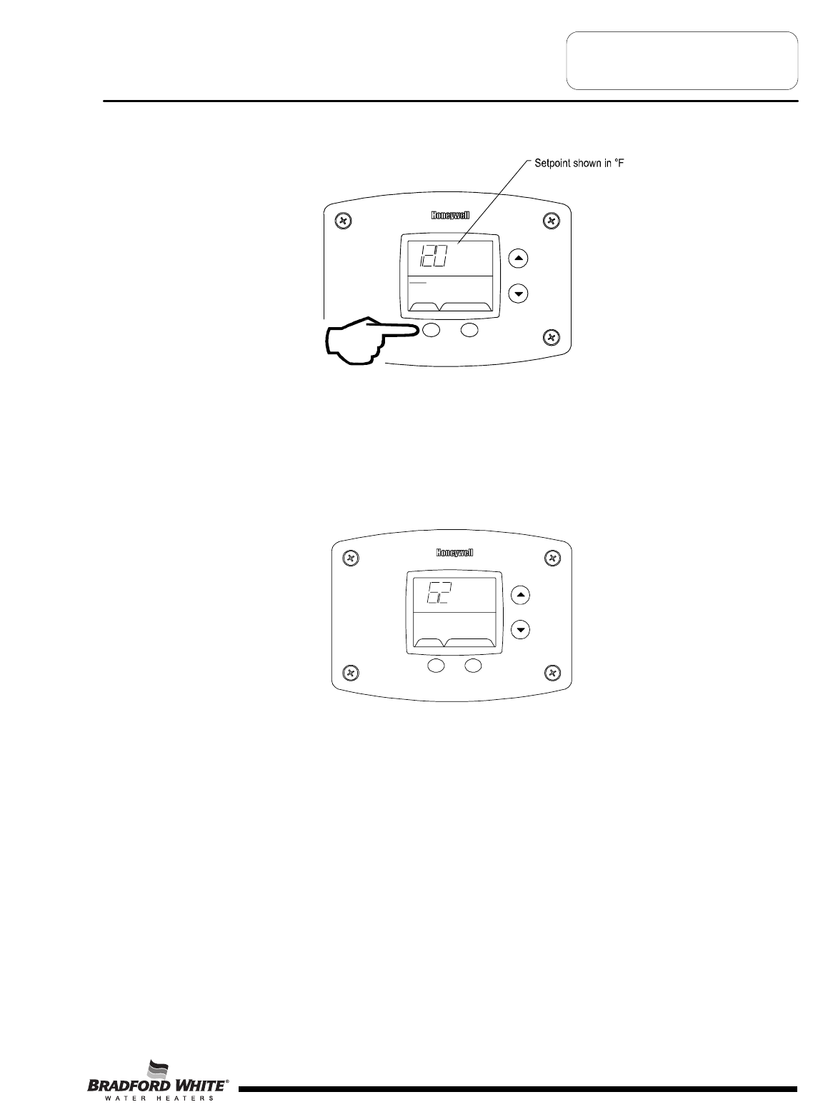
Step 5: Pressing “Select” button will return display to setpoint in format selected (°F or °C) immediately
SELECT SET
Status
°F
idle
Operation al
Lower S ensor
Error Codes and Error History Display:
If there is an operating problem with the water heater, an error code number will appear on the water heater display with
“Service Needed” to the right of the “Status” indicator. The error code label is located under the water heater display.
The following section in this Service Manual explains the error codes with corrective actions to repair the water heater.
Example of Error Code in the Display
Error Code History:
In “Service Mode” pressing the “Select” button after the “Software Version” (item 8 in the previously described sequence
of service modes) will show an error code history, if there have been any previous operating problems with the water
heater. If the display shows --, there is not a current error code.
The Water Heater Display will provide up to 10 previous error codes. The oldest error code will be stored in code index
#1 and the most recent in code index #10.
Page 19
Troubleshooting
SELEC T
idle
Servic e Needed
Lockout RESET
19
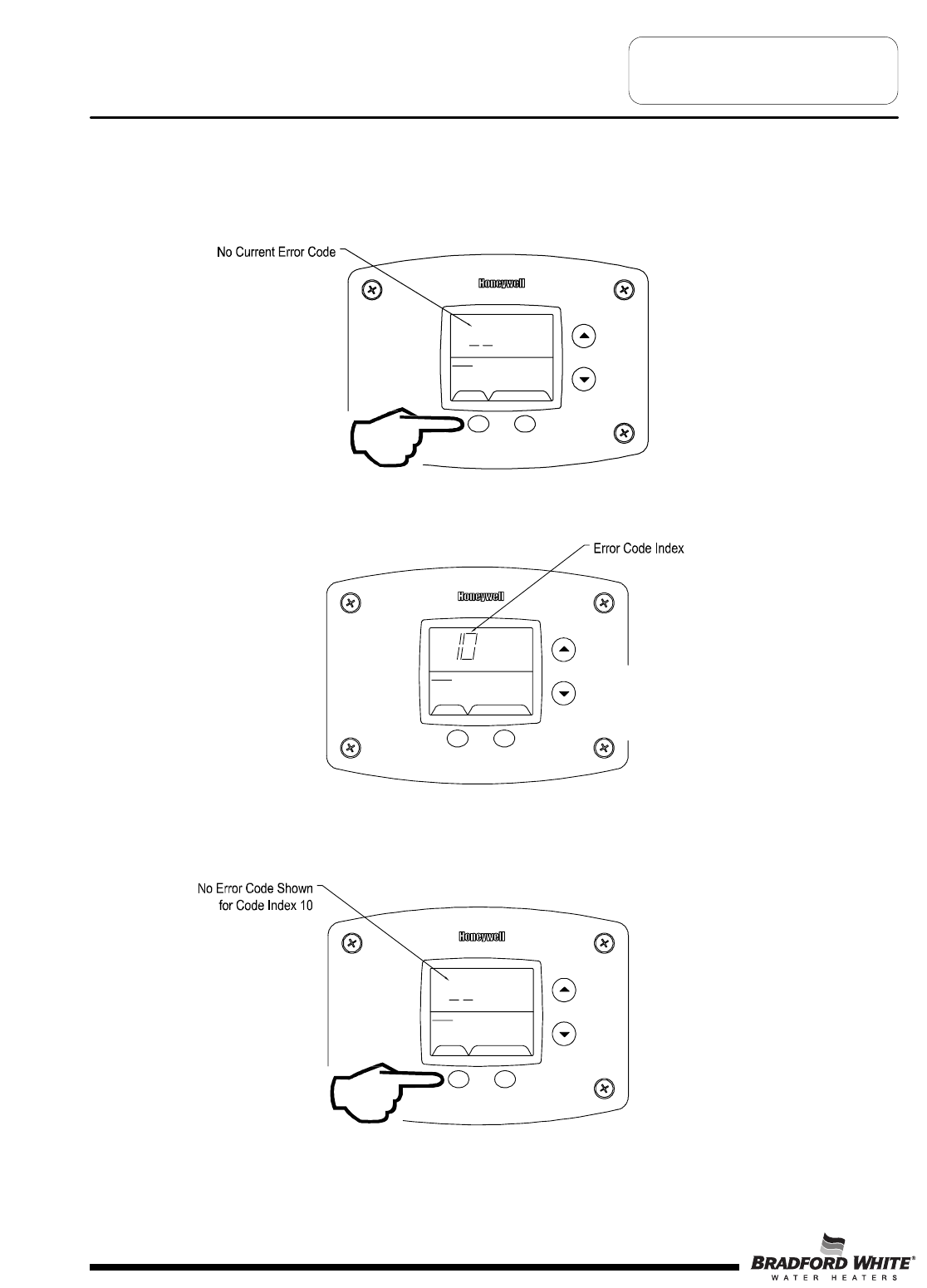
To view previous error codes:
Step 1:
In “Service Mode press the “Select” button until the next display after the “Software Version”. If there are no current
error codes, the display will show -- .
SELECT SET
Status
°F
idle
Operational
Step 2:
Press the “Temperature Down” button to select the error code index, starting with the most recent error code “10”.
SELECT SE
T
Status
idle
Operational
%
Step 3:
Press the “Select” button to view the error code for “code 10”. If there is a number displayed, note what the number is.
The label next to the water heater display will identify the code number. If no number is displayed with only a “--“ in the
water heater display, then there has not been an error code for error code index 10.
SELECT SET
Status
idle
Operational
Page 20
Troubleshooting
20
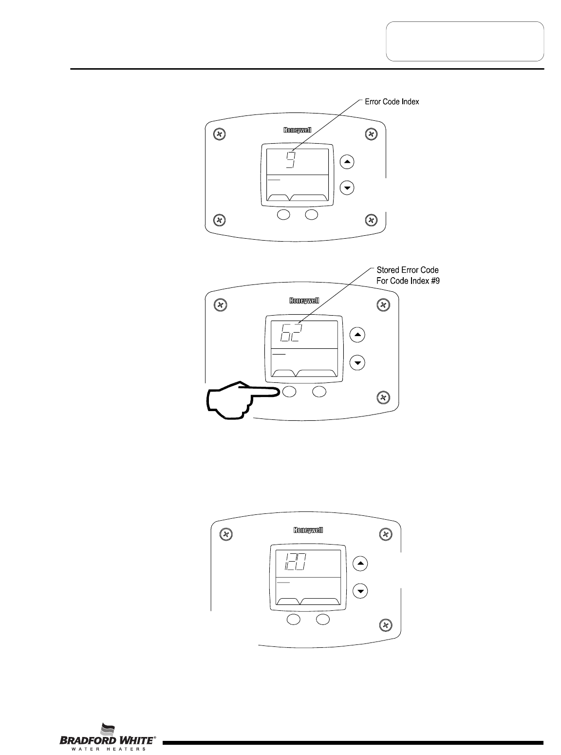
Step 4:
Press the “Temperature Down” button to change to the previous code index, code #9.
SELECT SET
Status
idle
Operational
%
Step 5:
Press the “Select” button for code index #9 to view if there are any code numbers.
SELECT SET
Status
idle
Operational
Step 6:
Continue pressing the “Temperature Down” button to change to the next error code index and press “Select” to view the
error code number, if any, for that index number. Continue on to index #1, the oldest error code index. The water
heater display will store up to 10 error codes with the oldest code starting in code index #1 with the most recent code in
code index #10.
Step 7: 10 seconds after the last button press, the Water Heater Display will revert back to the current error code
display. To exit Service Mode, either wait 30 seconds or press Temperature Up button and Select Button for 3 seconds.
Page 21
Troubleshooting
SELECT SET
Statu
s
°F
idl
e
setpoint
Operational
&%
Exiting Service Mode
21
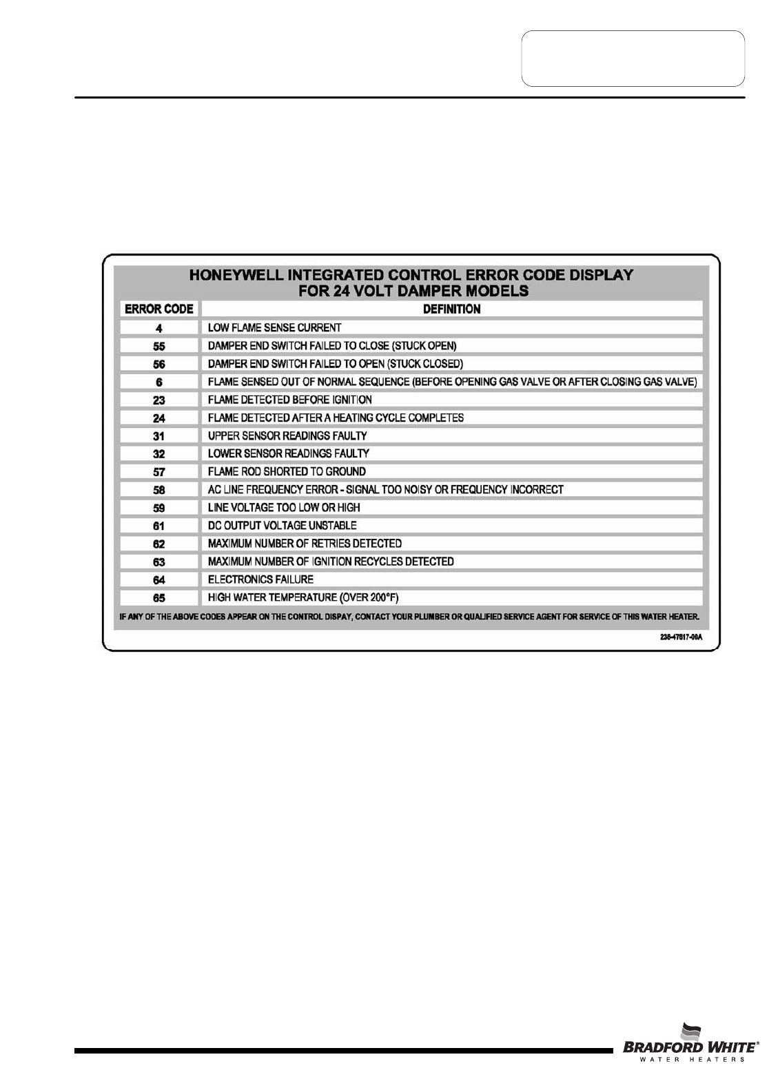
ERROR CODE DEFINITIONS
If the water heater has an operating problem, there will be a number in the water heater display with
“Service Needed” shown below the error code number. Note the error code and the definition in the
chart below. This label appears on the control box under the water heater display. The following
sections will provide instructions for servicing each error code.
Page 22
Troubleshooting
22
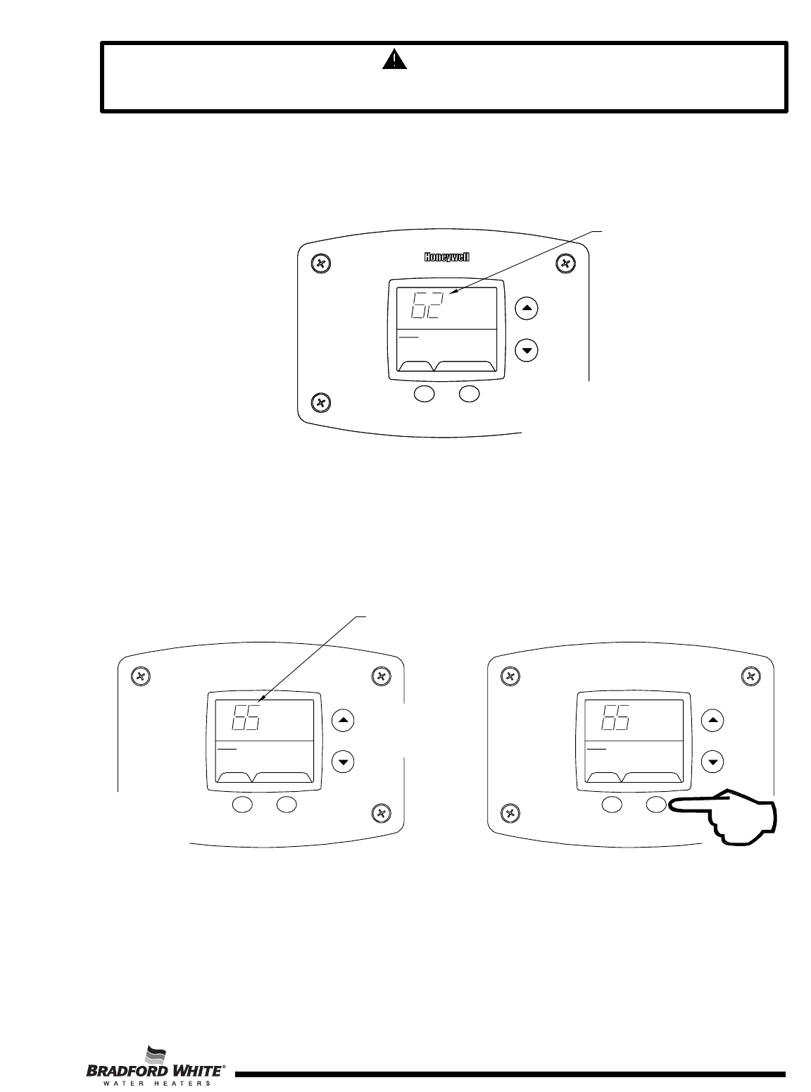
WARNING
The following procedure is for service and installation personnel only. Resetting lockout
conditions without correcting the malfunction can result in a hazardous condition.
If an error code is displayed (except for #4, low flame sense current), the water heater will be in a “lockout condition”
with the water heater display showing the error code number and “Service Needed” in the status section of the
display window. Error codes 62 (maximum number of retries detected) and 63 (maximum number if ignition
recycles detected) are “Soft Lockouts” in which the control can be reset in the “User Mode” by pressing the lower
right button under “Lockout Reset” shown in the lower right portion of the display. The control will also go through 3
attempts to relight the burners every hour in the soft lockout condition.
All other error codes will put the water heater into a “Hard Lockout” condition, in which the water heater will not
operate and cannot be reset in the “User Mode”. To reset a hard lockout, first enter the “Service Mode” described
earlier by pressing both the “Temperature Up” and “Select Buttons” at the same time for 3 seconds. Then press the
lower right button under “Lockout Reset” in the water heater display and hold for 3 seconds.
Lockout RESET
SELECT
Status Service needed
%
Error Code Shown in
Water Heater Display
Press for 2 seconds
Page 23
&
SELECT SET
Status Service Needed
%
SELECT Lockout RESET
Status Service Needed
Error Code Shown in
Water Heater Display
Step 1: Press for 3 seconds
to enter service mode.
Step 2: Press for 3 seconds to
reset control in service mode.
Resetting Error Codes in Hard Lockout Condition
23
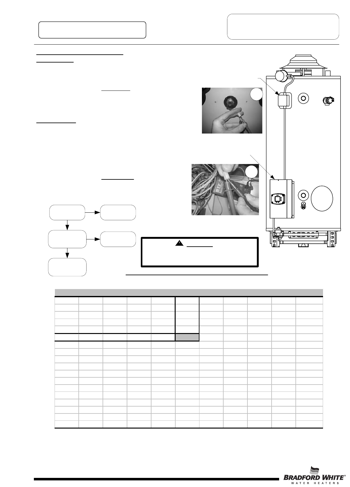
SERVICE PROCEDURE D24-I
Thermostat Circuit Testing
CAUTION
Be Careful When Making Voltage
Measurements or Jumping Terminals
Not to Damage or Deform Connectors or
Connector Pins.
DANGER
120 volt exposure. To avoid personal injury,
use caution while performing this procedure.
WARNING!
Do not reset the display from the hard lockout
state without correcting the cause of the
overheating condition.
Check continuity of wire harness to affected sensor. Measurement
of ohmeter should be close to 0 ohms. Replace wire harness if high
resistance is measured (over 0.5 ohms) Check wires for intermittent
connections, shorts, frayed insulation. Replace if necessary
(see photo 8)
Turn power on to water heater.
Run water heater through heating cycle and verify proper operation.
Sensor temperature can be viewed when burner shuts off (see
section on viewing the display in “Service Mode”.
This procedure assumes the flue damper is in working order. Be sure damper opens under its own power when the
thermostat circuit is by-passed. Damper must be open or removed during this test. Do not force damper open using your
hands or tools.
Turn power “OFF”.
Draw water to cool tank below 120 deg. F
Check lower sensor. Is the sensor fully inserted into the well?
Sensor is held in place with a clip fastened to the well (see photo 9)
Check lower sensor wire making sure it is not damaged or has
breaks in the wire insulation. Check upper harness wires to upper
sensor, if used (some models).
If sensor clip is damaged
replace clip. Replace lower
sensor if damaged.
Check Sensor Resistance
(see “Sensor Resistance
Testing” section & photo 7)
Y
N
Page 24
Measuring upper
sensor resistance
through wire
harness
(disconnected at
control board).
Checking
continuity of
upper sensor wire
harness.
Removing lower
sensor from well.
Held in place by a
clip fastened to
well shoulder.
Condition: Water Heater Not Operating
Display shows error code “65”
High Water Temperature (over 200 deg. F)
If wire harness checks out O.K.check resistance of sensor. Refer to
section on Sensor Resistance Testing. If sensor resistance is not
near the values shown in the table, then replace upper or lower
sensor as indicated by error code number.
Unplug or disconnect electrical power to the water heater
Condition: Water Heater Not Operating
Display shows error code “31” (Upper Sensor
Readings Faulty) or error code “32” (Lower Sensor
Readings Faulty)
See next page
7
8
9
24
SERVICE PROCEDURE D24-I
Thermostat Circuit Testing
Condition: Water Heater Not Operating
Display shows error code “65”
High Water Temperature (over 200 deg. F)
Continued
WARNING!
Do not operate water heater without verifying that the overheating condition has been corrected.
Once cause of overheating condition has been diagnosed
and corrected, the control may be reset
Reconnect and switch on power to the water heater.
Enter service mode on the water heater display (see
illustration)
Press button under “Lockout Reset” and hold for 3
seconds.
Set thermostat to the desired setting.
Water heater should start.
Monitor temperatures for one complete heating cycle
making sure the maximum tank temperature remains well
below 200 deg. F
Page 25
25
°F012345678 9
40 26109 25400 24712 24045 23399 22771 22163 21573 21000 20445
50 19906 19383 18876 18383 17905 17440 16990 16553 16128 15715
60 15314 14925 14548 14180 13823 13477 13140 12812 12494 12185
70 11884 11592 11308 11032 10763 10502 10248 1000 9760 9526
80 9299 9078 8862 8653 8449 8250 8057 7869 7685 7507
90 7333 7165 7000 6839 6683 6531 6383 6238 6098 5961
100 5827 5697 5570 5446 5326 5208 5094 4982 4873 4767
110 4663 4562 4464 4368 4274 4183 4094 4006 3922 3839
120 3758 3679 3602 3527 3453 3382 3312 3244 3177 3112
130 3048 2986 2925 2866 2808 2752 2697 2643 2590 2538
140 2488 2439 2391 2344 2298 2253 2209 2166 2124 2083
150 2043 2004 1966 1928 1891 1856 1820 1786 1753 1720
160 1688 1656 1625 1595 1566 1537 1509 1481 1454 1427
170 1402 1376 1351 1327 1303 1280 1257 1235 1213 1191
180 1170 1150 1129 1110 1090 1071 1053 1035 1017 999
190 982 965 949 933 917 901 886 871 857 842
200 828 814 801 788 775 762 749 737 725 713
In Degrees F
Sensor Resistance at Various Temperatures
Example: If water temperature is 84°F, then the resistance through the sensor would be 8449 (see shaded area).
NOTE: Sensor resistance increases as the temperature falls.
Page 26
SERVICE PROCEDURE D24-I
Thermostat Circuit Testing
Upper thermister location
(applicable models)
Lower thermister
access located inside
control box.
Sensor Resistance Testing
Upper Sensor
1. Determine resistance value of upper sensor. Test across
grey wires.
2. Draw quart of water off T&P valve. Using a thermometer,
determine water temperature.
3. Use table below to verify correct resistance per water
temperature measured.
Lower Sensor:
1. Determine resistance value of lower sensor. Test across
center wire (common) to each outside wire. Resistance of both
thermisters in the lower sensor should be close to each other.
If the resistance values for both thermisters are not close to
each other, replace the lower sensor. The dual thermisters are
used to provide high limit protection in case the thermostat
circuit fails to shut off the water heater.
2. Draw quart of water off Drain Valve.
Using a thermometer, determine water temperature.
3. Use table below to verify correct resistance per water
temperature measured.
Are readings
correct?
NReplace
thermister
Y
Check harness
continuity.
Continuity okay?
Y
Replace
control board
Replace
harness
N
CAUTION
Be Careful When Making Resistance
Measurements Not to Damage or
Deform Connectors or Connector Pins.
Conditions: Upper or Lower Sensor Reading
Faulty, High Water Temperature, or suspect
thermostat is not accurate.
Checking resistance of
upper sensor
Checking resistance of
lower sensor (center and
outside pins)
10
11
26
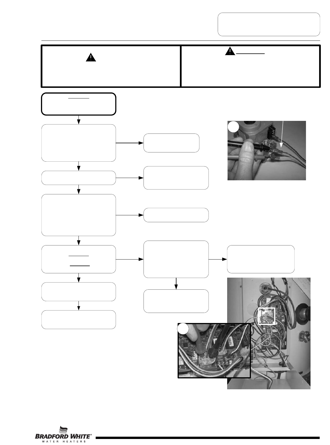
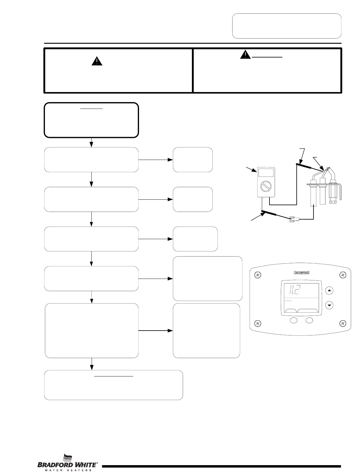
SERVICE PROCEDURE D24-II
Pilot Operation Testing
CAUTION
Be Careful When Making Voltage
Measurements or Jumping Terminals
Not to Damage or Deform Connectors or
Connector Pins.
DANGER
120 volt exposure. To avoid personal injury,
use caution while performing this procedure.
Condition:
Pilot will not light or stay lit,
Error codes 62, or 63 shown on Water
Heater Display
Is there 22-27 volts AC output across
terminal pins 8 & 2 on “Control” plug
of Control Board? Carefully insert
meter probe in wire plug to check pin
terminals. Make sure control is in the
trial for ignition sequence (see
Sequence of Operation).
(see photo 13)
N
Y
Loosen pilot tubing connection at
the gas valve and soap test.
Is there pilot gas flow out of the
gas valve? See pilot illustration
for pilot inspection. (Wires must
be connected to gas valve during
this test).
Tighten pilot tube connection at
the gas valve. Check incoming
gas pressure to water heater. if
okay, replace gas valve
Check for clogged or kinked pilot
tube, clogged pilot orifice. Clean
or replace as needed.
(see “Pilot Burner Inspection”)
Is there 22-27 volts AC input across
wire leads
“MV/PV” & “PV” (yellow & red wires)
at Gas Valve?
(see photo 12)
Check wire harness for damage or
loose connections. Repair or replace
as needed.
Reset control by pressing the lower
right button under “reset” on the
display for 3 seconds. Does control
board start ignition sequence and
start sparking (sparking noise at pilot
or at board)
Replace control board
12
Check across “MV/PV” & “PV” Wire
leads to gas valve
Y
YY
N
N
Replace control board.
Is there spark at the pilot?
Check for:
Loose or damaged ignition wire
Grounded pilot electrode
Damaged pilot.
Y
N
Checking for 24
volts output to
pilot valve
(yellow and red
wire pin
terminals) on
control board
“control” plug.
N
Turn on power to the water heater
and verify proper operation
Page 27
11
13
27
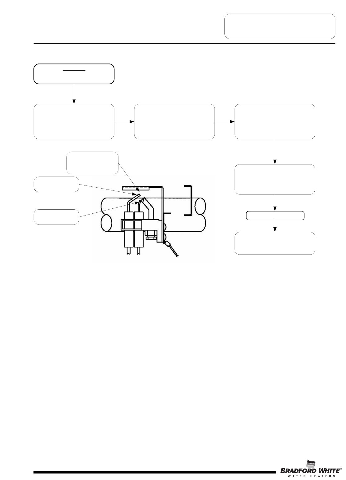
Condition:
Error code 57: Flame Rod Shorted
to Ground
Disconnect power. Shut off gas
supply to water heater. Slide out
burner assembly (see section on
“removing pilot and main burner
assembly”).
SERVICE PROCEDURE D24-II
Pilot Inspection
Check to see if pilot shield is touching
pilot flame sensor or flame sensor
touching pilot hood. Bend shield to
prevent interference or replace pilot
shield.
Check pilot flame sense wire for
broken insulation. Replace pilot if
defective
Reinstall pilot and burner assembly.
Reconnect gas line union, turn on
gas.
Make sure pilot shield
clears flame sense rod
Check for Gas Leaks
Page 28
Reconnect power and verify proper
ignitions.
Flame Sense Rod
Spark Electrode
28
SERVICE PROCEDURE D24-II
Pilot Operation Testing
CAUTION
Be Careful When Making Voltage
Measurements or Jumping Terminals
Not to Damage or Deform Connectors or
Connector Pins.
DANGER
120 volt exposure. To avoid personal injury,
use caution while performing this procedure.
Condition:
Pilot lights, no or low flame signal. Control
Display shows “4” or “62” for Error Codes
(Service Needed). Control continues to spark
until system “Lock Out”.
Main burner will not light.
The microamp output of the pilot may be
checked by entering “Service Mode” on the
water heater display and pressing “Select”
until the flame current is shown. The control
must be in the heating mode with the pilot lit
to display a reading. See section on
accessing service mode on the water heater
display.
Micro-amp readings
0.000 Micro Amp = Replace control board or pilot if wire is
damaged.
1.0 micro amp or less = Clean pilot flame rod or replace pilot.
Check for loose or damaged ground wire(s)
from gas valve to control board. Check
continuity of wires with ohmeter. Are ground
wires okay?
Check for loose or damaged flame sense
lead from pilot to Control Board. (see
illustration to the right). Is flame sense lead
okay?
Repair wire lead
or replace pilot.
Repair ground
wire(s) or replace
as needed.
NOTE:
Check continuity of sense lead
to flame rod. If no continuity,
clean pilot flame rod or replace
pilot. Check pilot flame
appearance - if weak check for
clogged pilot orifice, bent pilot
tubing, or low inlet gas
pressure.
(see above illustration)
Y
Y
N
N
Check venting conditions or negative
pressure.
Is vent system okay?
Correct improper
venting condition.
Refer to Installation
Instructions
N
Is heater condensing causing pilot
interruption?
Make sure pilot shield is in place
and not bent or damaged (refer
to section on main burner and
pilot assembly) . Determine
cause for condensing and
correct.
(Possible under sized water
heater or high demand periods.)
Y
Y
N
Pilot flame sensor microamp output
shown in display using service mode.
Pilot must be lit to get reading.
Multi-meter set
to check
continuity.
Flame rod
Meter
Probe
Meter
Probe
Checking pilot flame sensor wire and flame
rod for continuity.
Page 29
Heating Flame Current
ȝA
SELECT SE
T
Status Operational
29
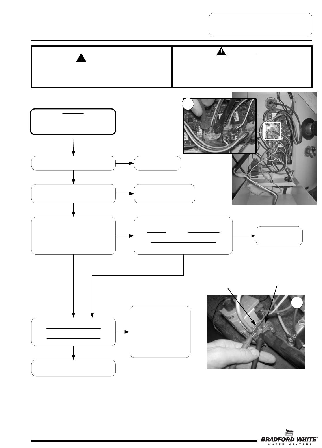
SERVICE PROCEDURE D24-III
Main Burner Operation Testing
CAUTION
Be Careful When Making Voltage
Measurements or Jumping Terminals
Not to Damage or Deform Connectors or
Connector Pins.
DANGER
120 volt exposure. To avoid personal injury,
use caution while performing this procedure.
Condition:
Main burner will not light,
Display shows “Heating” under temperature
setpoint.
Tank is cold.
Is Pilot lit? See “Pilot Will Not
Light”
Does control board continue to spark with
pilot lit?
See “Pilot Lights, No Flame
Signal”
Insert meter probes into back of
“Control” plug on control board to contact
pins for measuring voltage.
Is there 22-27 volts AC across
pin terminals 5 & 8? (Refer to wiring
diagram also see photo 14)
Disconnect brown wire lead from
“MV” terminal of gas valve.
Is there 22-27 volts AC across
brown wire lead & ground?
(see photo 15)
Replace control board.
Be sure control display is showing “Heating”,
pilot is lit and control is not sparking.
Recheck voltage across control board
pin terminals 5 & 8 (MV & MV/PV)
Is voltage present?
Check wire harness for damage or loose
connections. Repair or replace as needed.
Check incoming gas pressure
to gas valve and manifold
pressure to burners (See next
page for procedure for
checking manifold pressure). If
inlet gas pressure is O.K.,
replace gas valve. (See photo
on next page for gas valve
inlet pressure tap)
N
Y
NN
Y
N
Y
Y
N
Y
Checking MV &
MV/PV control plug
pins to gas valve
for 24 volts output
during heating
cycle (pilot must be
lit with no
sparking).
Brown wire disconnected
from “MV” terminal of gas
valve
Ground lug of
gas valve
Checking main valve (MV) voltage to gas valve.
Page 30
15
11
14
30
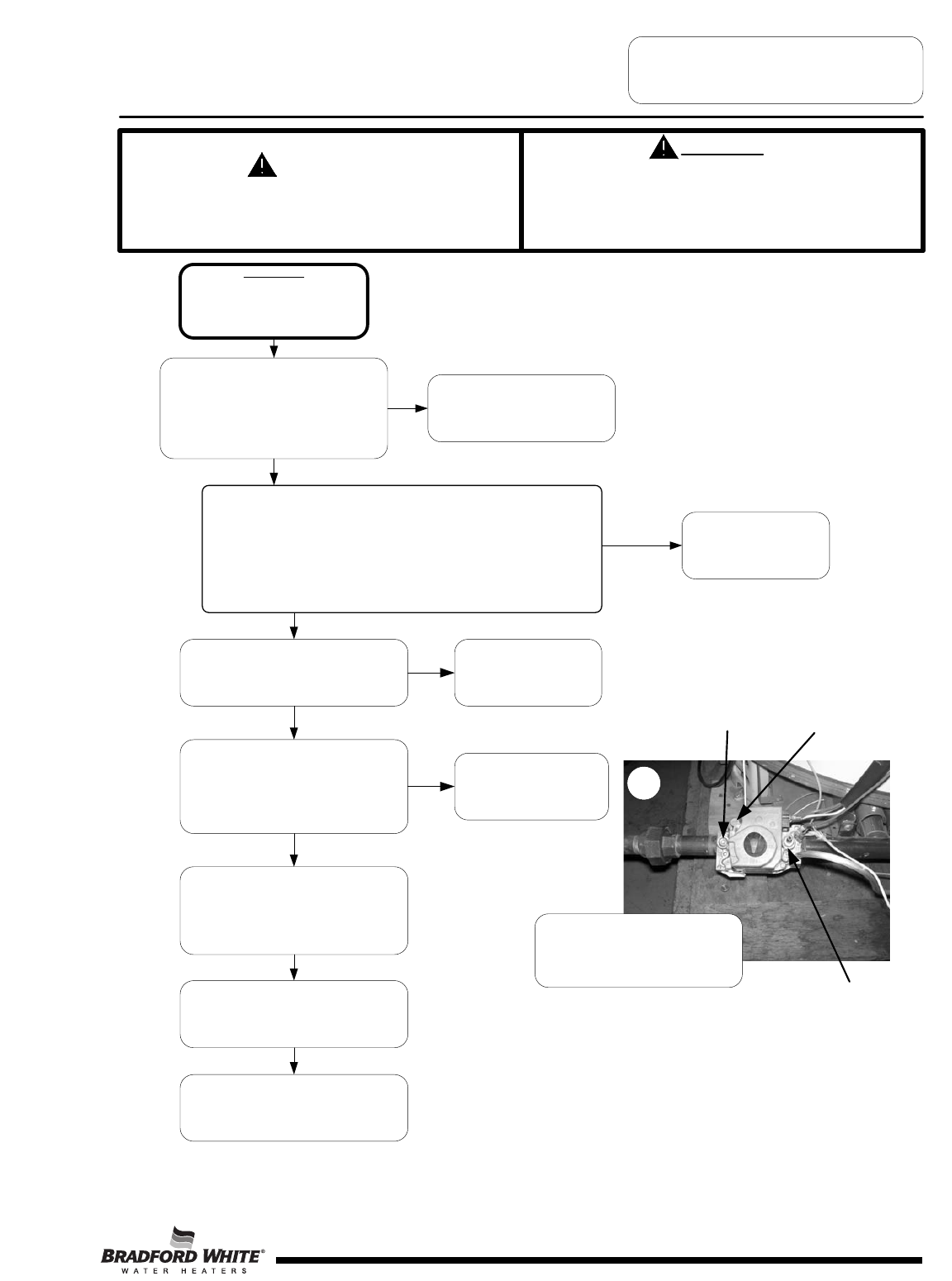
SERVICE PROCEDURE D24-III
Main Burner Operation Testing
CAUTION
Be Careful When Making Voltage
Measurements or Jumping Terminals
Not to Damage or Deform Connectors or
Connector Pins.
DANGER
120 volt exposure. To avoid personal injury,
use caution while performing this procedure.
Condition:
Main burner short cycles.
Control Display may show error
code “63, 57, or 4” and be in
“Soft Lockout” state.
Check gas inlet pressure to the water
heater gas valve.
Line pressure should be:
Nat. = Min. 5.5" W.C.: Max. 14.0" W.C.
LP = Min. 11.0" W.C.; Max. 14.0" W.C.
Is gas pressure within proper
specification? (see photo below)
Determine cause of incorrect gas
pressure and correct. Contact
your gas supplier.
Check venting conditions, clogged vent,
down drafts or negative building
pressure
Is vent system okay?
Correct improper venting
condition. Refer to
Installation Instructions
N
Is there sufficient combustion air being
supplied to the water heater? Are there
combustion air openings or supply pipes
to the room? Open access door to the
utility room to see if problem is
corrected.
Provide proper
combustion air to water
heater. Refer to
Installation Instructions
N
Check burner tubes for scale or debris
build-up. Clean burner as necessary.
(see Main Burner and Pilot Removal and
Inspection)
Check tank flues for blockage or debris
build-up causing restriction.
(see Flue Baffle Removal, Inspection)
Check for unstable pilot flame or
oxidation of the flame rod on pilot
causing weak pilot signal. Make sure
pilot shield is in place and does not
touch pilot flame sensor.
(See Pilot Inspection section)
Line gas
pressure port
Manifold Pressure Port with hose
barb inserted for measuring
pressure
N
Y
Y
Page 31
Check manifold pressure. See photo on lower right section of page for
manifold pressure tap location. Refer to water heater rating label for
specified manifold pressure. If the manifold pressure is not within 0.3"
w.c. of the specified pressure, then remove the regulator cap from the
gas valve and turn plastic screw clockwise to increase pressure and
counterclockwise to decrease pressure. Be sure inlet gas pressure is at
least 1" w.c. above the manifold pressure. Replace regulator screw and
pressure tap cap when finished. Is manifold pressure O.K.?
Gas Valve pressure
regulator cap (adjustment
screw accessible by
removing cap screw)
16
Replace Gas Valve.
N
Y
Y
Connect hose barb to manifold
pressure port shown above, then
connect monometer to measure
gas manifold pressure.
31
SERVICE PROCEDURE D24-IV
Main Burner & Pilot
Removal and Inspection
WARNING
Heater components may be HOT when performing the following steps in this procedure.
Take necessary precaution to prevent personal injury.
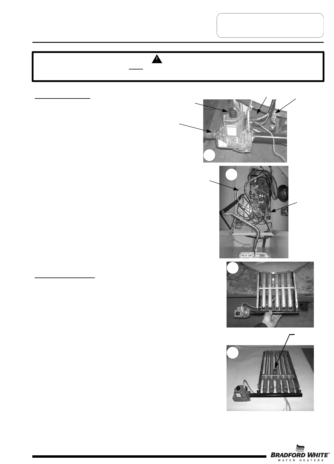
Main Burner Removal
Step 1. Disconnect (un-plug) water heater from
electrical supply.
Step 2. Turn “OFF” gas supply to water heater.
Step 3. Rotate gas valve control knob to the “OFF” position
(see photo 17).
Step 4. Disconnect Gas supply line from the gas valve
(see photo 17).
Step 5. Disconnect wire leads from gas valve
(see photo 17).
Step 6. Disconnect white flame sense wire & orange ignition
wire from Control Board (see photo 18).
Step 7. Remove the two burner rack mounting screws (see photo 17).
Step 8. Slide complete burner rack out from heater
(see photo 19).
Step 9. To install burner, reverse above procedure.
Step 10. Check for gas leaks and verify proper operation.
Gas Valve
Control Knob
Gas Supply
Line
Gas Valve
Wire Leads Burner Rack
Mounting
Screw
Main Burner Inspection
Step 1. Burner tubes should be free of any flue
scale or other debris. Clean
burner tubes using a stiff brush and/or
shop vac. Burner ports should have uniform
openings. Replacement is recommended for
burners where port area is deteriorated or
other unintended openings are present.
Step 2. Insure pilot shield is in place (see photo 20).
Step 3. Inspect pilot position to insure smooth burner
ignition from pilot flame. Pilot should be
mounted using the two mounting screws through
the burner support bracket resulting in a level
pilot position.
19
Pilot
Shield
17
20
Pilot spark wire
(Orange)
Pilot Flame Sense
Wire (White)
Page 32
18
32
SERVICE PROCEDURE D24-IV
Main Burner & Pilot
Removal and Inspection
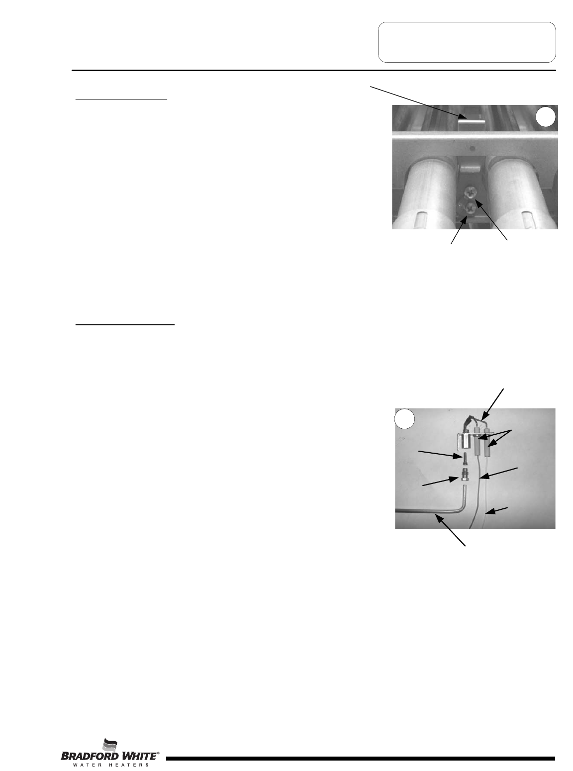
Pilot Burner Removal
Step 1. With burner rack removed from heater, disconnect
pilot tube connection from gas valve
Step 2. Remove the two pilot burner mounting screws
securing the pilot and pilot shield in place.
Step 3. Remove pilot shield and pilot from burner rack.
Step 4. To install pilot burner and pilot shield, reverse above
procedure. Be sure to reconnect green ground wire.
Pilot Shield
Pilot & Pilot Shield
Mounting Screws
Ground Wire
Location
Pilot Burner Inspection
Step 1. Inspect pilot for the following:
a) Broken or cracked ceramic insulators. If found,
pilot must be replaced.
b) Damaged electrode or flame sense wire. If found,
pilot must be replaced.
c) Oxidation build-up on flame rod. Clean flame rod
or replace pilot as necessary.
Step 2. Inspect pilot orifice:
a) Remove 7/16" ferrule nut from bottom of pilot.
b) Remove pilot tube and orifice from pilot.
c) Inspect pilot tube for blockage. Clean or replace
as necessary.
d) Inspect pilot orifice for blockage. Clean or replace
as necessary.
Flame Sense
Wire
Ignition
Wire
Ceramic
Insulators
Flame
Rod
Pilot
Orifice
7//16"
ferrule
Nut
Aluminum
Pilot Tubing
Page 33
21
22
33
SERVICE PROCEDURE D24-IV
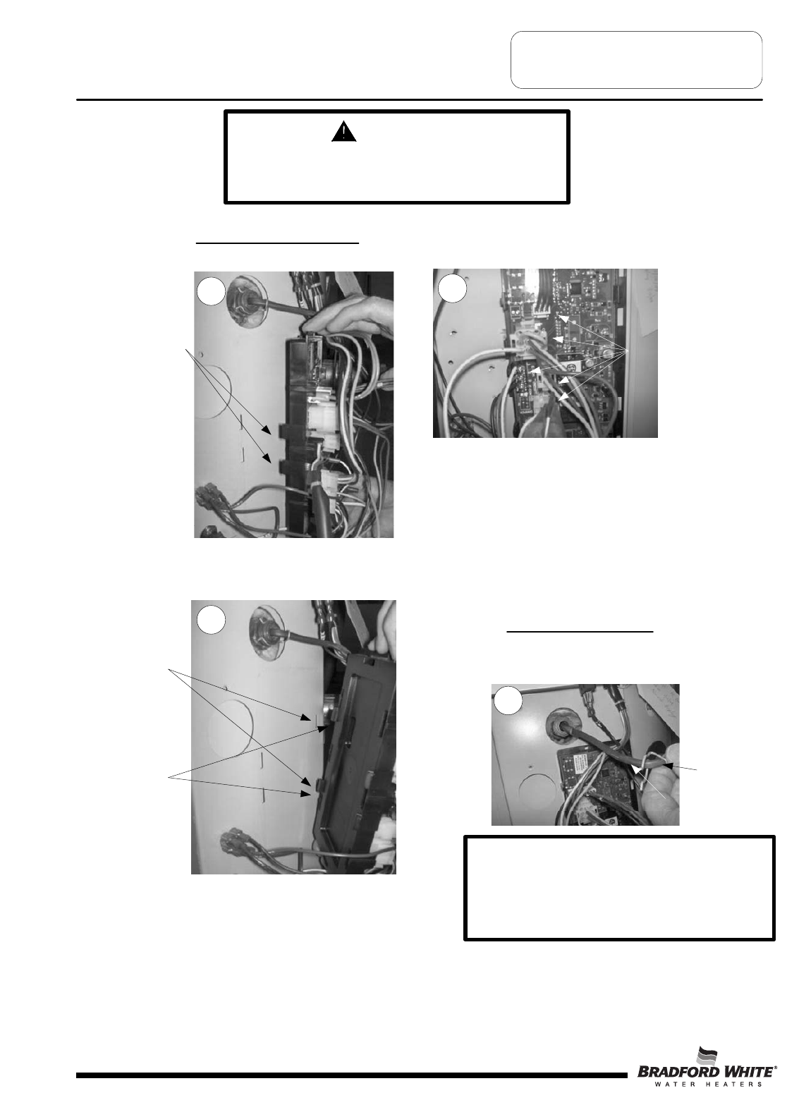
Control Board Replacement
Control board replacement
Step 1: Disconnect Power
Depress
plastic
tabs
Slots in
control panel
Unhook tabs
from control
panel slots
To remove lower sensor
Remove clip, pull sensor out.
Step 2: Unplug wire connections from board.
Pull out sensor
Remove clip
Wire connections
DANGER
120 volt exposure. To avoid personal injury,
unplug while performing this procedure.
Page 34
23
25
24
26
Step 3: To remove board, tilt control panel to the right
and slide control hook tabs from slots in control panel.
IMPORTANT
When replacing lower sensor, make sure
sensor is fully inserted into the well and
securely held by the clip on the well groove.
(see photo 25)
34
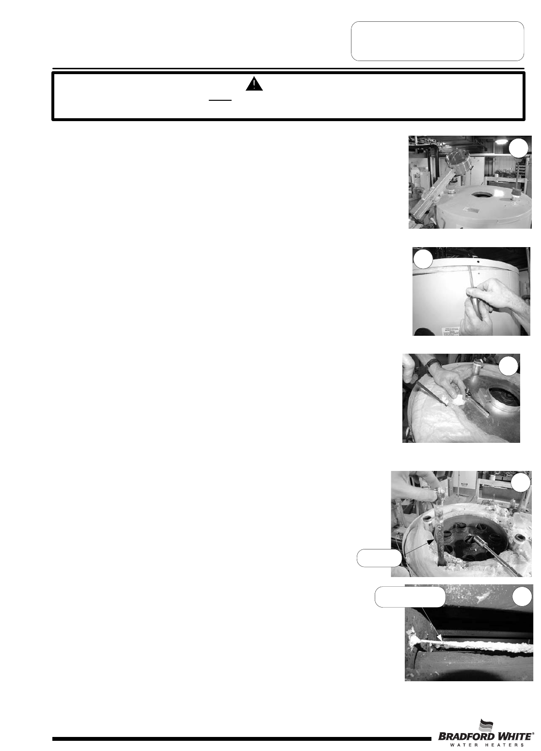
SERVICE PROCEDURE D24-V
Flue Baffle Removal, Inspection
Step 1. Disconnect (unplug) water heater from electrical supply.
Step 2. Disconnect venting from draft diverter and remove draft
diverter from top of water heater.
Step 3. Disconnect flue damper from wire harness and remove
flue damper from top of water heater (see photo 27).
Step 4. If required, turn “OFF” water supply & disconnect top plumbing
connection from top of water heater.
Step 5. Remove screws holding jacket head to top of water heater
and remove jacket head from top of water heater. Note, it may
be necessary to use a screw driver to pry underneath
jacket head (see photo 28).
Step 6. Remove insulation from top of water heater to expose
collector cover.
Step 7. Remove screws from side (or top) of collector cover. Note, it may be
necessary to chisel away some foam to access screws (see photo 29).
Step 8. Remove collector cover from water heater by using
pipe wrench as illustrated in photo 30.
Step 9. Remove flue baffles from water heater. Note, it may be necessary
to use pliers to loosen and remove baffles from flue tubes (see photo 31).
Step 10. Visually inspect flue baffles. Flue baffles may show signs
of oxidation; this is normal. If the oxidation has deteriorated
any portion of the flue baffle, replacement is recommended.
If any restrictors are missing, replacement is recommended.
Step 11. Upon completion of inspection or subsequent replacement,
reinstall flue baffles into heater.
Step 12. Reinstall collector cover and insulation over collector cover.
Step 13. Reinstall jacket head, flue damper and draft diverter. Reconnect venting.
Step 14. Reconnect plumbing connection to top of water heater
& turn on water supply if required.
Step 15. Check for leaks and verify proper operation.
WARNING
Heater components may be HOT when performing the following steps in this procedure.
Take necessary precaution to prevent personal injury.
Page 35
28
27
29
30
Flue Baffle
31
35
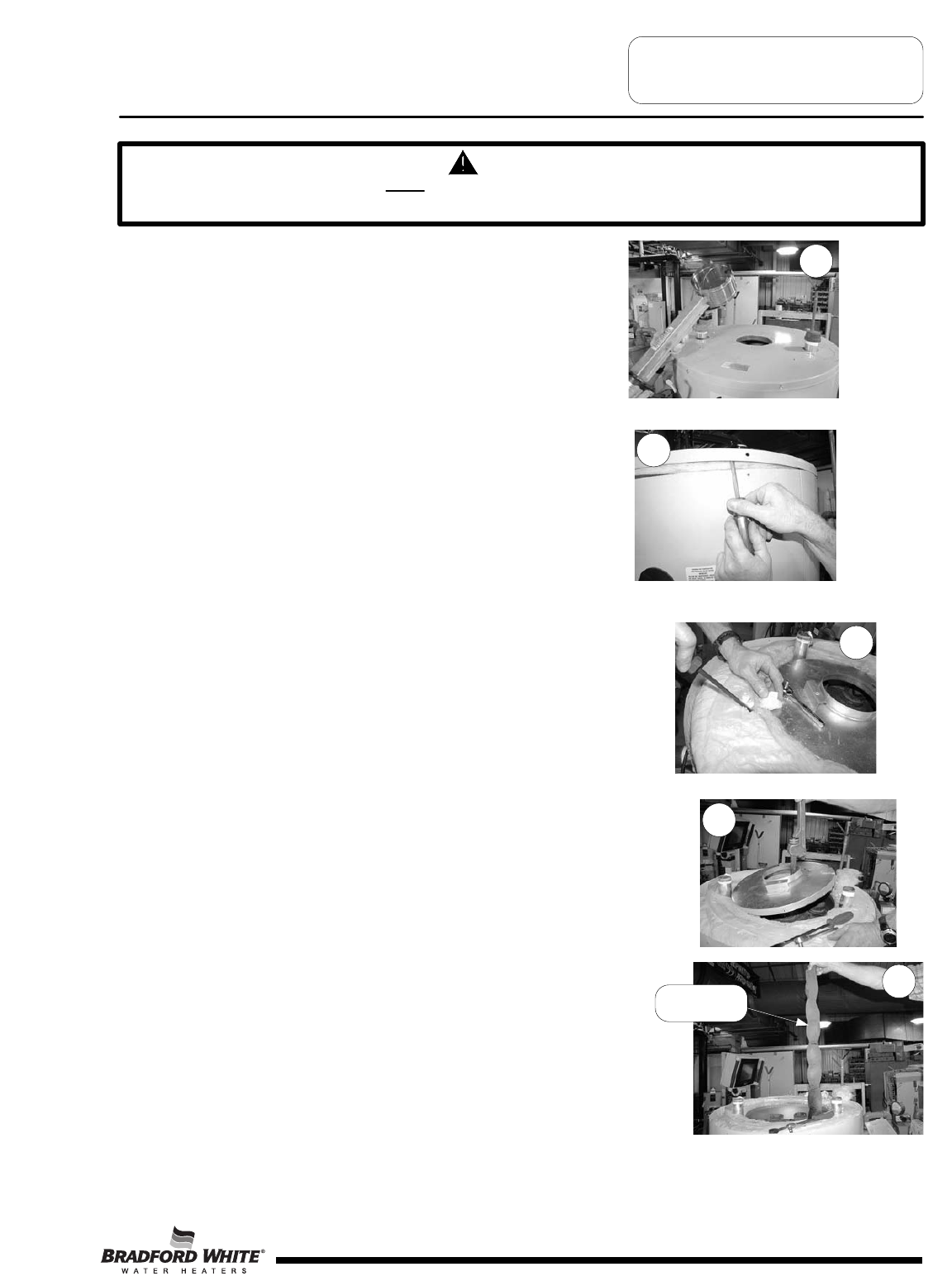
SERVICE PROCEDURE D24-VI
Anode Removal and Inspection
Step 1. Disconnect (unplug) water heater from electrical supply.
Step 2. Turn “OFF” water supply to water heater.
Step 3. Open a near by hot water faucet to relieve tank pressure.
Step 4. Connect hose to drain valve of water heater and route to an open drain. Open
drain valve and drain a minimum of 5 gallons of water from the water heater.
Close drain valve and disconnect drain hose from water heater.
Step 5. Disconnect venting from draft diverter and remove draft diverter from top of
water heater.
Step 6. Disconnect flue damper from wire harness and remove flue damper from top
of water heater (see photo 32).
Step 7. If required, turn off water supply and disconnect top plumbing connection from
top of water heater.
Step 8. Remove screws holding jacket head to top of water heater
and remove jacket head from top of water heater. Note, it may
be necessary to use a screw driver to pry underneath
jacket head (see photo 33).
Step 9. Remove insulation from top of water heater to expose collector cover,
remove if necessary. (see next page for approx. anode locations)
Step 10. Remove screws from side (or top) of collector cover. Note, it may be
necessary to chisel away some foam to access screws (see photo 34).
Step 11. Locate and remove anode rods from top of water heater (1-1/16 hex socket).
Note, anodes located outside of the collector (see photo 35) may require foam
to be chiseled away to access anode rods. (see next page for approx. anode locations)
Step 12. Visually inspect anode rod. Anode rod may show signs of depletion;
this is normal. If the anode shows signs of depletion
(approximately 5/8", see photo 36), replacement is recommended. If any of
the steel core of the anode is exposed, replacement is recommended.
Step 13. Upon completion of inspection or subsequent replacement,
reinstall anode rods into water heater.
Step 14. Check for leaks.
Step 15. Reinstall collector cover & insulation over collector cover.
Step 16. Reinstall jacket head, flue damper and draft diverter. Reconnect venting.
Step 17. Reconnect plumbing connection to top of water heater if required.
Step 18. Restore water supply and power to water heater.
Step 19. Verify proper operation.
WARNING
Heater components may be HOT when performing the following steps in this procedure.
Take necessary precaution to prevent personal injury.
Page 36
33
32
34
35
Anode
36
Replace Anode
36
Page 37
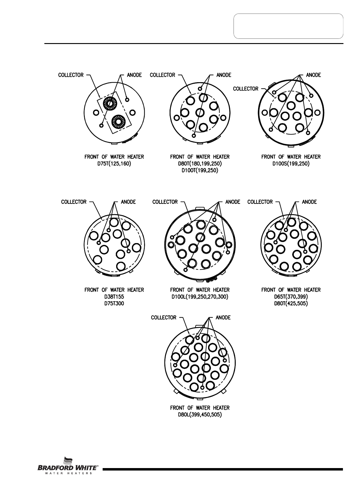
SERVICE PROCEDURE D24-VI
Anode Removal and Inspection
Approximate Anode Rod Locations
37
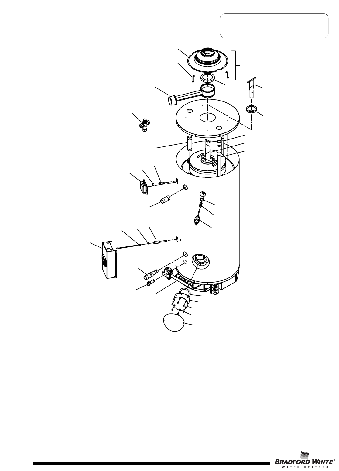
Generic Parts List
1. Draft Diverter w/Leg Kit
2. Draft Diverter
3. Draft Diverter Leg
4. Damper Outlet Reducer
5. Flue Damper
6. Hot Outlet Nipple
7. Cold Water Inlet Dip
Tube
8. Hex Head Anode
9. Flue Baffle
10. Flue Reducer
11. Flue Core
12. 1" x ¾" Reducer Bushing
13. Nipple T&P Valve
14. T&P Valve
15. Cleanout O-Ring
15A. Cleanout Gasket (ASME)
16. Cleanout Access Cover
16A. Cleanout Access Cover (ASME)
17. Cleanout Cover Screw
17A Cleanout Cover Screw (ASME)
18. Cleanout Jacket Cover
19. Thermostat Sensor Clip
20. Burner Assembly Complete
21. Brass Drain Valve
22. Cold Water Inlet Nipple (side)
23. Thermostat Well
24. Damper Harness
25. Lower Thermostat Sensor
26. Control Box Assembly Complete
27. Hot Water Outlet Nipple (side)
28. Upper Thermostat
29. Utility Cover
30. ASSE Approved Mixing Valve
31. Pipe Plug ¾ NPT
Page 38
2
3
54
30
6
28
29
27
19 23
26
25
22
21
20 15
15A
16/16A
17/17A
18
14
13
12
10
11
1
9
24
8
7
38
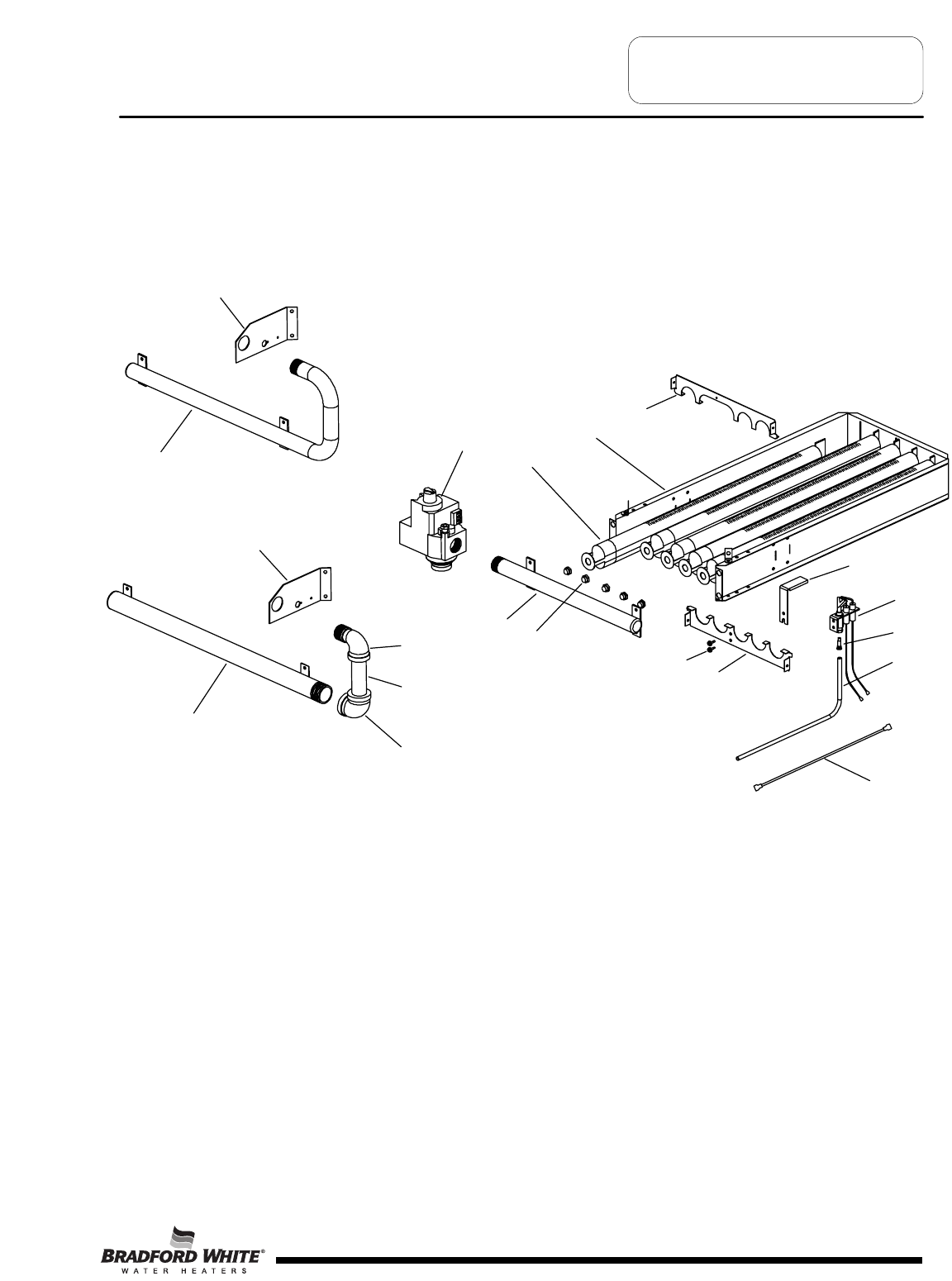
Generic Parts List
1A. Draft Panel
2A. Burner Rack
3A. Burner Tube
4A. Gas Valve
5A. Burner Manifold
6A. Main Burner Orifice
7A. Pilot Shield
8A. Pilot Burner
9A. Pilot Orifice
10A. Pilot Tubing
11A. Pilot Mounting Screw
12A. Burner Tube Support
13A. Manifold Bracket
14A. C-Cane Manifold
15A. Manifold Straight
16A. Manifold Bracket
17A. 90° Street Elbow Black
18A. 1" Down Pipe Nipple Black
19A. 1" 90° Elbow Black
20A. Ground Wire
Page 39
20
A
14
A
15
A
5A
13A
16A
4A
3A
6A
11A
12
A
9A
10A
8A
7A
2A
1A
19
A
18A
17
A
39
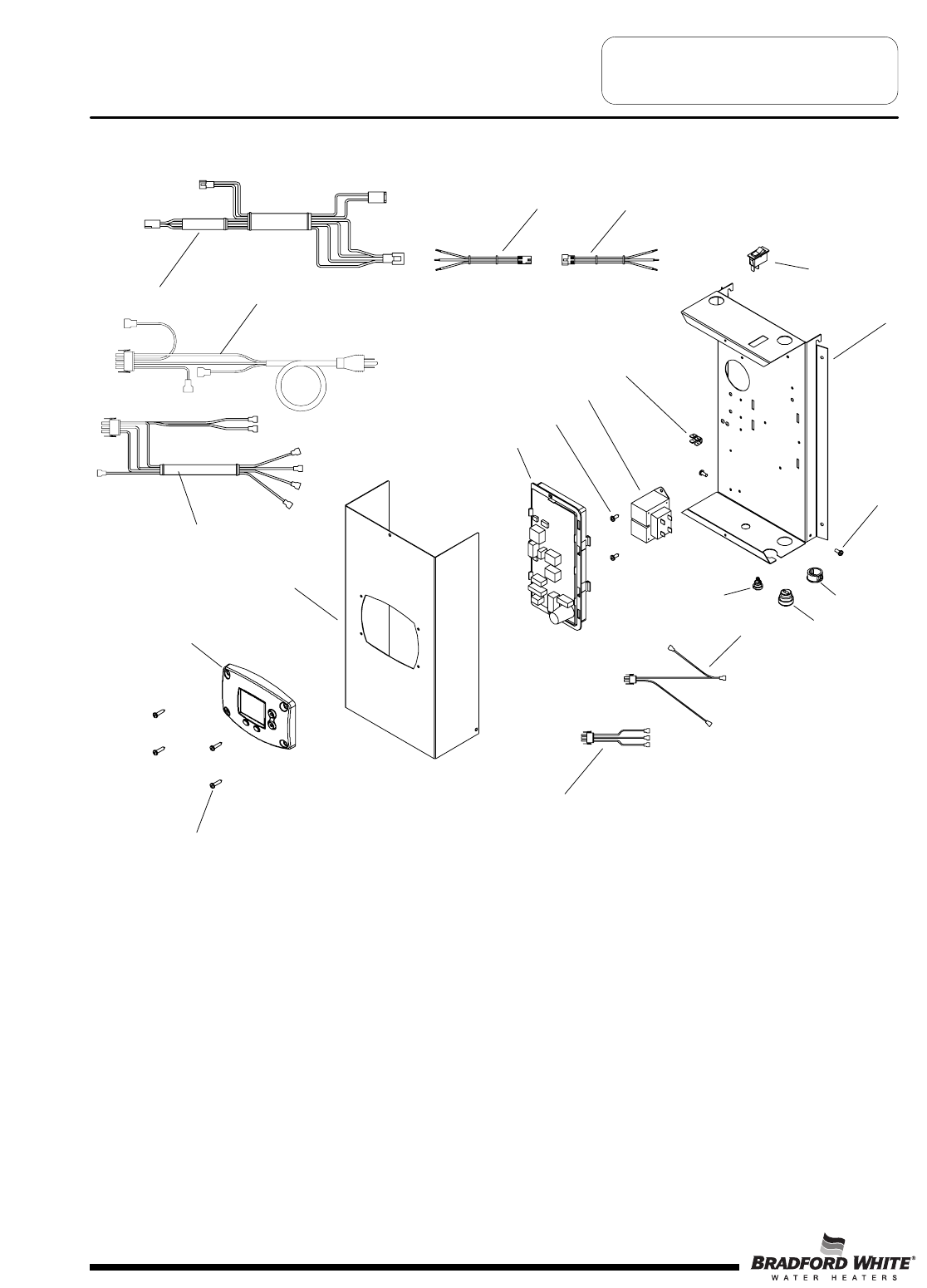
Generic Parts List
1B. Temperature Display
2B. Control Box Cover
3B. Integrated Control Board
4B. Screw 8-16 X ½ PHCR
5B. Transformer
6B. Ground Lug
7B. On/Off Switch
8B. Control Box Panel
9B. Screw 8/32 X ¼ PHCR
10B. 7/8" Snap Bushing
11B. Power Cord Strain Relief
12B. Pilot Wire Strain Relief
13B. Secondary Transformer Wiring Harness
14B. Primary Transformer Wiring Harness
15B. Screw 8-18 x ¾ PHCR
16B. Gas Valve Control Wiring Harness
17B. Damper Wiring Harness
18B. Power Cord
19B. Display Control Wiring Harness
20B. Display Cover Wiring Harness
Page 40
15B
1B
3B
4B
5B
6B
7B
8B
9B
13B
14B
17B 18B
16B
2B
19B 20B
11B
10B
12B
40
NOTES
AC Alternating Current
BTU/H British Thermal Units per Hour
CO Carbon Monoxide
CO2 Carbon Dioxide
DC Direct Current
ECO Energy Cut Off
GFI Ground fault interrupt
GPM Gallons per Minute
Hz Hertz
LED Light Emitting Diode
NOx Oxides of Nitrogen
NPT National Pipe Thread
PSI Pounds per Square Inch
VA Volt Amps
VAC Volts Alternating Current
W.C. Inches of Water Column
°C Degrees Centigrade
°F Degrees Fahrenheit
ȝA Micro Amp
Page 41
Glossary of Terms
41

NOTES
Page 34

NOTES
Page 34

Email
parts@bradfordwhite.com
techserv@bradfordwhite.com
www.bradfordwhite.com
