Bradfordwhite Canada Residential Boiler Wall Mounted Brute Lx Blxcw Blxhw Iomanual 1295A Bw User Manual
Residential Boiler Wall Mounted Brute Lx Blxcw Blxhw Iomanual 1295A Bw residential_boiler_wall_mounted_brute_lx_blxcw_blxhw_iomanual_1295a_bw residential_boiler_wall_mounted_brute_lx_blxcw_blxhw_iomanual_1295a_bw uploads wp-content bradfordwhitecorp :
2017-01-09
User Manual: Bradfordwhite Canada Residential Boiler Wall Mounted Brute Lx Blxcw Blxhw Iomanual 1295A Bw canada_residential_boiler_wall_mounted_brute_lx_blxcw_blxhw_iomanual_1295a_bw uploads wp-content bradfordwhitecorp :
Open the PDF directly: View PDF ![]() .
.
Page Count: 56
Brute LX
Installation and Operation Instructions Document 1295A
H2364001A
WARNING
If the information in this manual is not
followed exactly, a re or explosion may
result causing property damage, personal
injury or loss of life.
Do not store or use gasoline or other
ammable vapors and liquids in the vicinity of
this or any other appliance.
WHAT TO DO IF YOU SMELL GAS
• Do not try to light any appliance.
• Do not touch any electrical switch; do not
use any phone in your building.
• Immediately call your gas supplier from a
nearby phone. Follow the gas supplier's
instructions.
• If you cannot reach your gas supplier, call
the re department.
Installation and service must be performed
by a qualied installer, service agency, or gas
supplier.
FOR YOUR SAFETY: This product must be installed and serviced by a professional service technician,
qualied in hot water boiler and heater installation and maintenance. Improper installation and/or operation
could create carbon monoxide gas in ue gases which could cause serious injury, property damage, or
death. Improper installation and/or operation will void the warranty.
AVERTISSEMENT
Assurez-vous de bien suivres les instructions
données dans cette notice pour réduire au
minimum le risque d’incendie ou d’explosion
ou pour éviter tout dommage matériel, toute
blessure ou la mort.
Ne pas entreposer ni utiliser d’essence ou ni
d’autres vapeurs ou liquides inammables dans
le à proximité de cet appareil ou de tout autre
appareil.
QUE FAIRE SI VOUS SENTEZ UNE ODEUR DE
GAZ:
• Ne pas tenter d’allumer d’appareils.
• Ne touchez à aucun interrupteur. Ne pas vous servir
des téléphones dans le bâtiment où vous vous
trovez.
• Appelez immédiatement votre fournisseur de
gaz depuis un voisin. Suivez les instructions
du fournisseur.
• Si vous ne pouvez rejoindre le fournisseur de
gaz, appelez le sservice des incendies.
L’installation et l’entretien doivent être assurés par
un installateur ou un service d’entretien qualié
ou par le fournisseur de gaz.
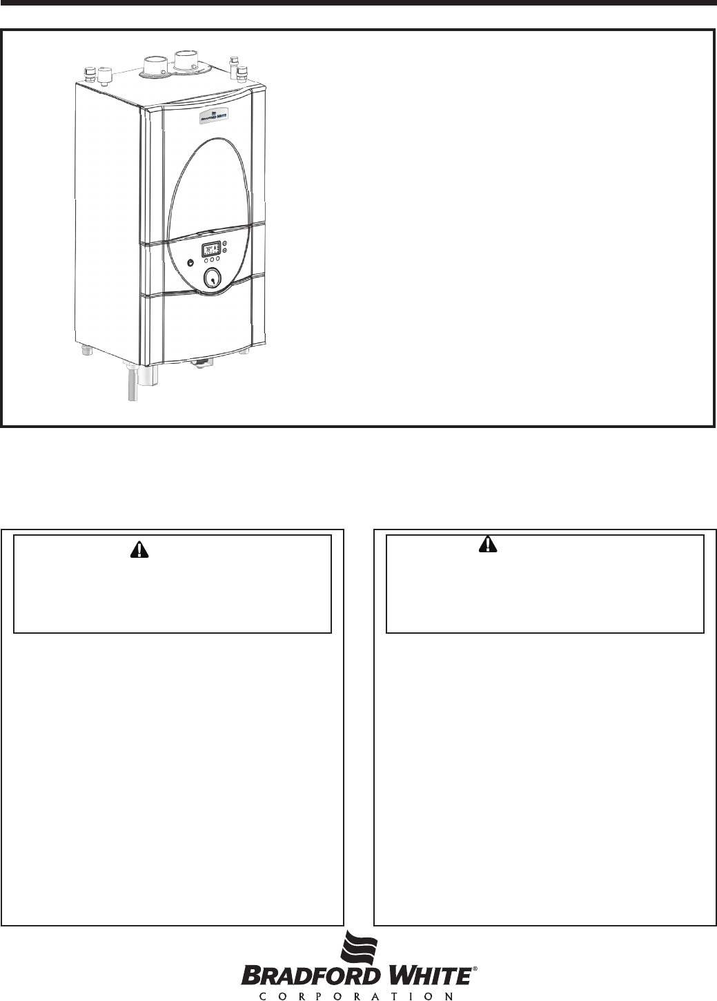
Installation and Operation
Instructions for
Wall-Mounted Modulating Boiler
Model BLXH
50, 75, 100, 125, 150, 175 & 220 MBH
Combination
Boiler and Water Heater
Model BLXC 125, 150 and 175 MBH

BRADFORD WHITE CORP
.
TABLE OF CONTENTS
SECTION 1.
General Information
1.1 Introduction ........................................................ 1
1.2 To Open the Brute LX ......................................... 1
1.3 Rating Plate ........................................................ 1
1.4 Model Nomenclature........................................... 1
1.5 Brute LX Overview .............................................. 2
1.6 Start Up / Shut Down Instruction (Decal) ............ 3
1.7 Dimensions for all Sizes ..................................... 4
1.8 Unpacking ........................................................... 6
1.9 Warranty ............................................................. 6
SECTION 2.
Locating the Appliance
2.1 Locating the Appliance........................................ 7
2.2 Correct Vent Distance
from Outside Wall or Roof Termination ............... 7
2.1 Wall Mount Hole Locations ................................. 8
SECTION 3.
Venting and Combustion Air
3.1 Combustion Air ................................................... 9
3.1.1 Combustion Air from Room................................. 9
3.1.2 Ducted Combustion Air ..................................... 10
3.2 Venting (Exhaust) ............................................. 10
3.2.1 About Common Venting .................................... 12
3.3 Locating Vent & Combustion Vent Terminals .... 13
3.3.1 Side Wall Vent Terminal .................................... 13
3.3.2 Side Wall Combustion Air Terminal ................... 13
3.3.3 Vertical Vent Terminal ....................................... 15
3.3.4 Vertical Combustion Air Terminal ...................... 15
3.3.5 Installations in the Commonwealth
of Massachusetts .............................................. 15
3.4 Common Vent Test ........................................... 16
SECTION 4.
Gas Supply and Piping
4.1 Gas Supply and Piping .......................................... 17
SECTION 5.
Pump Capacity
5.1 Brute LX Heating System Pump Capacity ............. 18
SECTION 6.
Water Connections
6.1 Central Heat System Piping.............................. 19
6.2 Cold Water Make-Up ........................................ 19
6.3 Freeze Protection ............................................. 19
6.4 Recognized Chemicals ..................................... 20
6.5 Domestic Hot Water Piping (DHW and BLXC) . 20
6.6 Indirect Water Heater Piping ............................. 20
6.7 Condensate Drain ............................................. 20
6.8 Piping Schematics ....................................... 21-26
SECTION 7.
Electrical Connections
7.1 Main Power ....................................................... 27
7.2 Pump Connections ........................................... 27
7.3 24Vac Transformer Circuit Breaker ................... 27
7.4 Central Heat - Call for Heat .............................. 27
7.5 Outdoor Air Temperature Sensor ...................... 27
7.6 Domestic Hot Water Connection ...................... 27
7.7 System Sensor
(lead lag/cascading operation only) .................. 27
7.8 External Control Connections ........................... 27
7.9 Ladder Diagram, Connections, and
Wiring Diagrams .......................................... 28-30

Brute LX
SECTION 8.
CONTROL Setup and Operation
8.1 Digital Display ................................................... 31
8.2 CONTROLLER Modes ..................................... 32
8.3 User Mode ........................................................ 33
8.4 Installer Mode ................................................... 34
8.5 Service Mode .................................................... 35
8.6 Modulation Control............................................ 35
8.7 Pump Control .................................................... 35
8.8 High Limit .......................................................... 36
8.9 Stack Temperature ............................................ 36
8.10 Domestic Hot Water Temperature..................... 36
SECTION 9.
OPERATION Modes
9.1 Hydronic Heating Demand................................ 36
9.2 Hydronic Heating with Outdoor Reset .............. 36
9.3 Hydronic Heating Using External
Modulation Control............................................ 36
9.4 Warm Weather Shutdown ................................. 37
9.5 Domestic Hot Water Demand (BLXC only) ....... 37
9.6 Domestic Hot Water Priority (BLXC only) ......... 37
9.7 Cascade Auto Conguration ............................. 38
SECTION 10.
Set Up Instructions
10.1 Filling the Boiler System ................................... 39
10.2 Starting the Burner after Set Up ....................... 39
10.2.1 Burner Operation ............................................ 39
10.2.2 Boiler Setup and Adjustment .......................... 40
10.3 Shutting Down the Brute LX ............................. 40
10.4 To Restart the Brute LX .................................... 40
SECTION 11.
Maintenance
11.1 System Maintenance ....................................... 42
11.2 Appliance Maintenance and Component
Description ........................................................ 42
11.2.1 Burner ............................................................... 42
11.2.2 Appliance Control ............................................. 42
11.2.3 Ignitor Assembly ............................................... 43
11.2.4 Flame Sensor ................................................... 43
11.2.5 Blower ............................................................... 43
11.2.6 Heat Exchanger Coils ....................................... 43
11.2.7 Gas Conversion ................................................ 44
SECTION 12.
Troubleshooting
12.1 Sequence of Operation .................................... 45
12.2 Short Cycling .................................................... 45
12.3 Error Codes ...................................................... 46
SECTION 13.
Replacement Parts
13.1 Exploded Parts Illustrations ............................. 48
BRADFORD WHITE CORP
.
THE
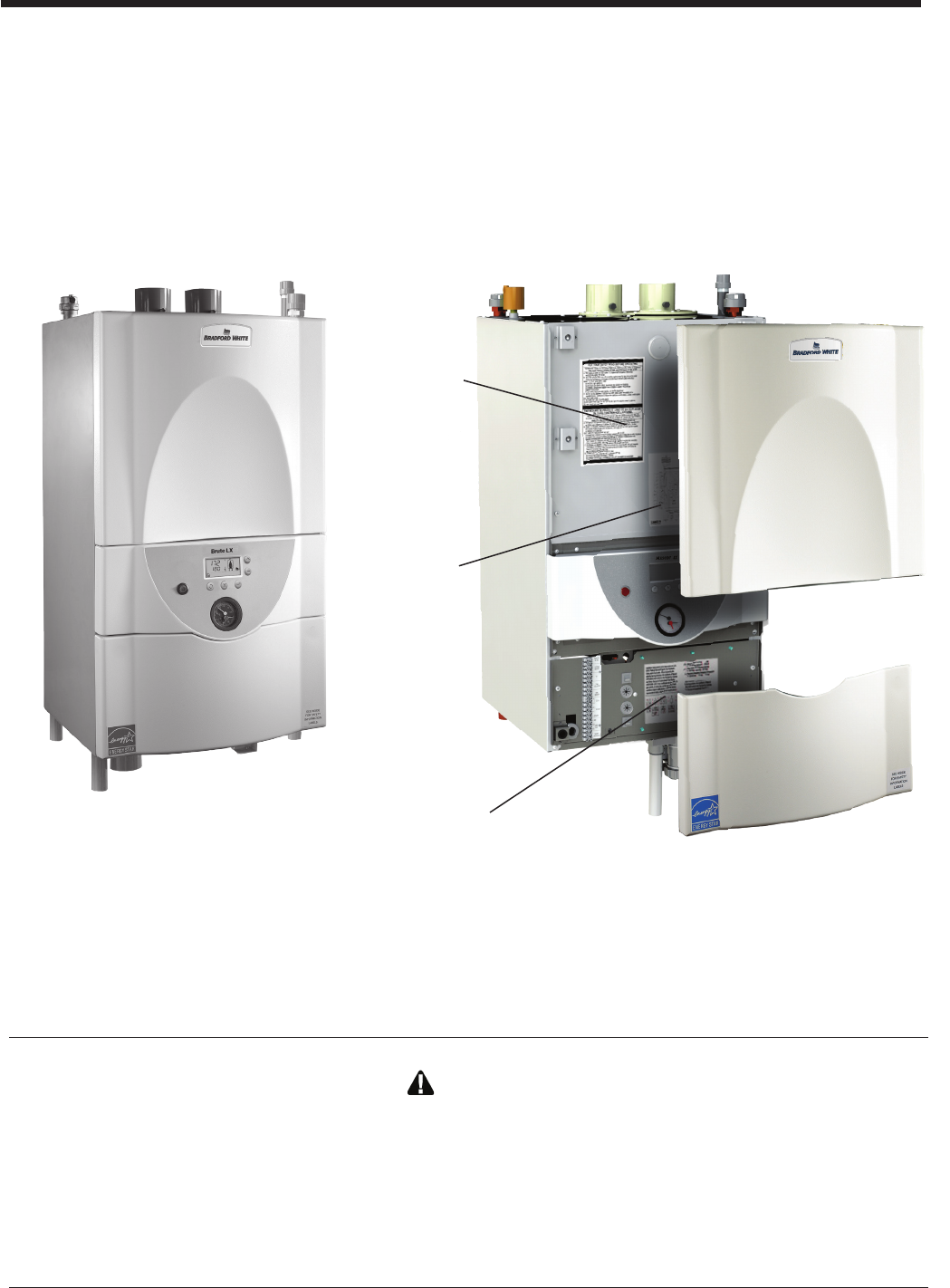
Figure 1. Opening the Brute LX.
The top and bottom panels come off when
pulled forward. This is true for all sizes.
START-UP
INSTRUCTIONS
SECTION 1.
General Information
WARNING
Brute LX units must be installed in accordance with the procedures detailed in this manual, or the Bradford White
warranty will be voided. The installation must conform to the requirements of the local jurisdiction having authority,
and, in the United States, to the latest edition of the National Fuel Gas Code, ANSI Z223.1/NFPA54. In Canada, the
installation must conform to the latest edition of CSA B149.1 Natural Gas and Propane Gas Installation Code, and/
or local codes. Where required by the authority having jurisdiction, the installation of Brute LX boilers must conform to
the Standard for Controls and Safety Devices for Automatically Fired Boilers, ANSI/ASME CSD-1. Any modications
to the boiler, its gas controls, or wiring may void the warranty. If eld conditions require modications, consult the
factory representative before initiating such modications.
WIRING
DIAGRAM
RATING PLATE
Brute LX

Page 1
Brute LX
Figure 1. Opening the 100, 125, 150, 175, and 220
Figure 2. Model Nomenclature
2 3 4 5 6 7 8 9 10 11 12 13
L X A X N
SERIES
L - SERIES
HEAT
EXCHANGER
LABEL
BRUTE
USAGE
H - HYDRONIC
C - COMBI
UNIT
SIZES
MBTU/h
50
75
100
125
150
175
220
FUEL
N - NATURAL
P - PROPANE
CONFIG
W - WALL
ALTITUDE
A - 0-10,000 FEET
REVISION
1 - FIRST
OPTIONS
X -
STANDARD
L - LWCO
PUMP OPTIONS
N - WITH PUMP
1
B
1.1 Introduction
This manual provides information necessary for the
installation, operation, and maintenance of Bradford
White Brute LX appliances. Read it carefully before
installation. All application and installation procedures
should be reviewed completely before proceeding with
the installation. Consult the Bradford White factory,
or local factory representative, with any problems or
questions regarding this equipment. Experience has
shown that most operating problems are caused by
improper installation.
All installations must be made in accordance with
1) American National Standard Z223.1/NFPA54-Latest
1.3 Rating Plate
The Rating Plate is located on the metal pan behind the
lower plastic panel. It contains Model Nomenclature,
Manufacture Date, Model Number, Serial Number,
Output Rating, and all other information pertaining to
your Brute LX. .
1.2 To Open the Brute LX
To open the Brute LX for maintenance and servicing,
the upper and lower plastic panels are designed to 'pop'
off when they are pulled forward. See Figure 1 and
Figure 3. This will expose the top metal panel which
covers the heat exchanger, and the lower panel which
holds the low voltage connections and covers the pump
and other lower components.
To remove these panels for further access into the
Brute LX, there are two screws that hold each panel in
place. Remove the 2 screws on the upper panel and slide
the upper metal panel up and out. For the lower panel,
remove the 2 screws and hinge the lower metal panel
downward.
The center panel containing the On/Off Switch, Gauges,
and User Interface is not removable.
Edition “National Fuel Gas Code” or
2) CSA B149.1 “Natural Gas and Propane Installation
Code” and with the requirement of the local utility or
other authorities having jurisdiction. Such applicable
requirements take precedence over the general
instructions contained herein.
All electrical wiring is to be done in accordance with
the local codes, or in the absence of local codes, with: 1)
The National Electrical Code ANSI/NFPA No. 70-latest
Edition, or 2) CSA STD. C22.1 “Canadian Electrical
Code - Part 1”. This appliance must be electrically
grounded in accordance with these codes.
Nomenclature
(1) Label
B = Brute
(2-3) Series Designation
LX = L Series Heat Exchanger
(4) Usage
H = Modulating Boiler
C = Combination Boiler and Water Heater
(5) Conguration
W = Wall Hung
(6-8) Size
50 = 50,000 BTU/hr input
75 = 75,000 BTU/hr input
100 = 100,000 BTU/hr input
125 = 125,000 BTU/hr input
150 = 150,000 BTU/hr input
175 = 175,000 BTU/hr input
220 = 220,000 BTU/hr input
(9) Fuel
N = Natural Gas
P = LP Gas (propane)
(10) Altitude
A = Up to10,000 Feet: de-rate applies*
(11) Revision
1 = First version
(12) Options Code
X = Standard
L = Low water cutoff
(13) Pump Options
N = With Pump
1.4 Model Nomenclature
The Model Nomenclature is shown on your Rating Plate
and consists of a series of letters and numbers
( Nomenclature ) that further identies the
characteristics of your Brute LX. See Figure 2.
* For high altitude applications, boiler must be
de-rated 4% per 1000 feet above 2000 feet.
*
Page 2
BRADFORD WHITE CORP
.
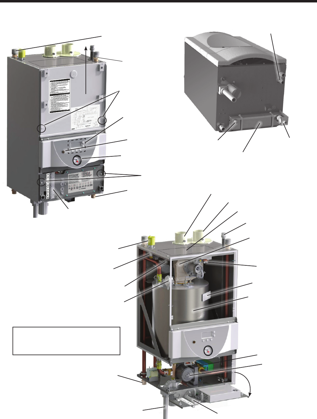
Figure 3. Location of Components
1.5 Brute LX, Overview
CENTRAL HEAT
IN CONNECTION
(RETURN WATER)
CENTRAL HEAT
IN CONNECTION
(RETURN WATER)
CENTRAL HEAT OUT
CONNECTION
(SUPPLY WATER)
CENTRAL HEAT OUT
CONNECTION
(SUPPLY WATER)
SHOWN WITH THE FRONT PANELS OFF,
AND A SIDE PANEL MISSING FOR VISUAL
PURPOSES.
COMBUSTION INLET
HEAT EXCHANGER
ASME TAG
AUTOMATIC
AIR VENT
LOW WATER CUT OFF
(OPTIONAL)
EXHAUST
SERVICE HATCH
GAS SUPPLY
HEAT EXCHANGER
WATER PRESSURE
SWITCH
USER
INTERFACE
TEMPERATURE /
PRESSURE GAUGE
GAS VALVE
PUMP
HIGH VOLTAGE
FIELD CONNECTION
TERMINALS
LOW VOLTAGE
FIELD CONNECTION
TERMINALS
FOLDS DOWN
TO OPEN
BLOCKED VENT
PRESSURE SWITCH
COMBUSTION
AIR FAN
( BLOWER )
ON / OFF
SWITCH
2 SCREWS
2 SCREWS
LIFT
DHW
HOT OUT
GAS SUPPLY
DHW
COLD IN
DHW FLAT PLATE
HEAT EXCHANGER
(COMBINATION BOILERS ONLY)
BOTTOM
VIEW
3-WAY VALVE
CONDENSATE
TRAP
Page 3
Brute LX
Figure 4. Start Up / Shut Down Instructions (Decal)
(3).Turn manual gas cock "off"
H23377-
qualified service technician to inspect the appliance and to replace any gas control which
C. Do not use this appliance if any part has been under water. Immediately call a
D. TO TURN OFF GAS TO APPLIANCE
(1) SET SELECTOR SWITCH TO "OFF"(0) (2) Turn off all electric power to appliance
incendie ou une explosion pourrait se produire et causer des dommages
materiels, des blessures personnelles ou meme la mort..
PAR MESURE DE PRUDECE, LISEZ CE QUI SUIT AVANT
DE FAIRE FONCTIONNER L'APPAREIL
FOR YOUR SAFETY READ BEFORE OPERATING
may result causing property damage, personal injury or loss of life.
"WARNING: If you do not follow these instuctions exectly, a fire or explosion
"MISE EN GARDE: Si vous ne suivez pas ces instructions a la lttre, un
A. This appliance does not have a pilot. It is equipped with an ignition device that
automatically lights the burner.
B. BEFORE OPERATING smell all around the appliance area for gas. Be sure to smell
next to the floor because some gas is heavier than air and will settle on the floor.
WHAT TO DO IF YOU SMELL GAS
· Do not try to light appliance.
· Do not touch any electric switch: do not use any phone in your building
· Immediately call your gas supplier from a neighbor's phone. Follow the gas
supplier's instructions.
· If you cannot reach your gas supplier, call the fire department.
has been under water
A. Cet appareil n'est pas doté d'une veilleuse. Il est équipe d'un dispositif d'allumage
qui allume automatiquement le brûleur. Ne tentez pas d'allumer le brûleur manuellement.
B. AVANT D'UTILISER, vérifiez s'il n'ya pas d'odeur de gaz prés de l'appareil. Vérifiez
s'il n'ya pas d'odeur de gaz prés du plancher, car le gaz est plus lourd que l'air et peut
se déposer sur le plancher.
QUE FAIRE EN CAS D'ODEUR DE GAZ
• N'essayez pas d'allumer n'importe quelque appareil que ce soit.
• Ne touchez pas a un commutateur electrique. N'utilisez pas le téléphone de votre résidence.
• Appelez immédiatement votre fournisseur de gaz en utilisant le téléphone de votre
voisin. Suivez les instructions de votre fournisseur de gaz.
• Si vous ne pouvez joindre votre fournisseur de gaz, appelez le service des incendies.
C. N'utilisez pas cet appareil si l'une des pièces a été plongée sous l'eau.
Communiquez immédiatement avec un technicien de service qualifie afin qu'il inspecte
l'appareil et remplace toute pièce du système de commande et toute commande de
gaz qui aurait été plongée sous l'eau.
D. FERMETURE DE L'ALIMENTATION EN GAZ
(1) Poussez le bouton a bascule vers La position OFF (0).
(2) Coupez l'alimentation électrique â l'affairée.
(3) fermez le robinet de gaz manuellement vers OFF (la poignée est horizontale
1.6 Start Up / Shut Down Instructions
(Decal)
The Start Up / Shut Down Instruction (Decal) can be found
on the metal panel behind the Top Panel. See Figure 1.
This Decal is also referred to as the Operating Instructions
Label and/or Warning Label.
Page 4
BRADFORD WHITE CORP
.
31
4"
8
31
4"
8
73
4"
20
N
17"
43
TOP
M
O
83
4"
22
23
4"
7
GAS
GAS
HYDRONIC
OUTLET
HYDRONIC
OUTLET
ELIMINATION
AIR
AIR
VENT
INLET
EXHAUST
VENT
HYDRONIC
INLET
HYDRONIC
INLET
H
F
G
E
A
D
C
CONDENSATE
TRAP
MASCOT LX BOILER
MODELS, PIPING
INSTALL LOCATION
DIM A
HYDRONIC
OUT
DIM B
HYDRONIC
OUT
DIM C
HYDRONIC
IN
DIM D
HYDRONIC
IN
DIM E
GAS
DIM F
GAS
DIM G
CONDENSATE
OUTLET
DIM H
CONDENSATE
OUTLET
DIM J
DHW OUT
DIM K
DHW OUT
DIM J
DHW IN
DIM L
DHW IN
DIM M
CABINENT
HEIGHT
DIM N
CABINENT
DEPTH
75,000 BTU 1" (3)15-3/4" (40)3-3/4" (9) 9-1/4" (24)8" (20)1-1/2"
(4)5-3/4" (14)15-1/2" (39) -- -- -- -- 30-1/2" (78)15-1/4"
(39)
125,000 BTU 1" (3)15-1/2" (39)1-1/4" (3)12-3/4"
(33)11" (28)1-1/4"
(3)9-1/2" (24) 14-3/4" (37) 2-3/4" (7) 12-3/4"
(33)
2-3/4"
(7)2" (5) 30-1/2" (78) 18" (46)
175,000 BTU 1-1/2" (4)15-1/4" (39)1-3/4" (4)13" (33)11-1/4"
(28)
2-3/4"
(7)-- -- 2-3/4" (7)12-3/4"
(33)
2-3/4"
(7)1-3/4" (5)35-1/2" (90) 18" (46)
BOTTOM
SIDE
FRONT
B
DHW
OUTLET
DHW
INLET
J
L
K
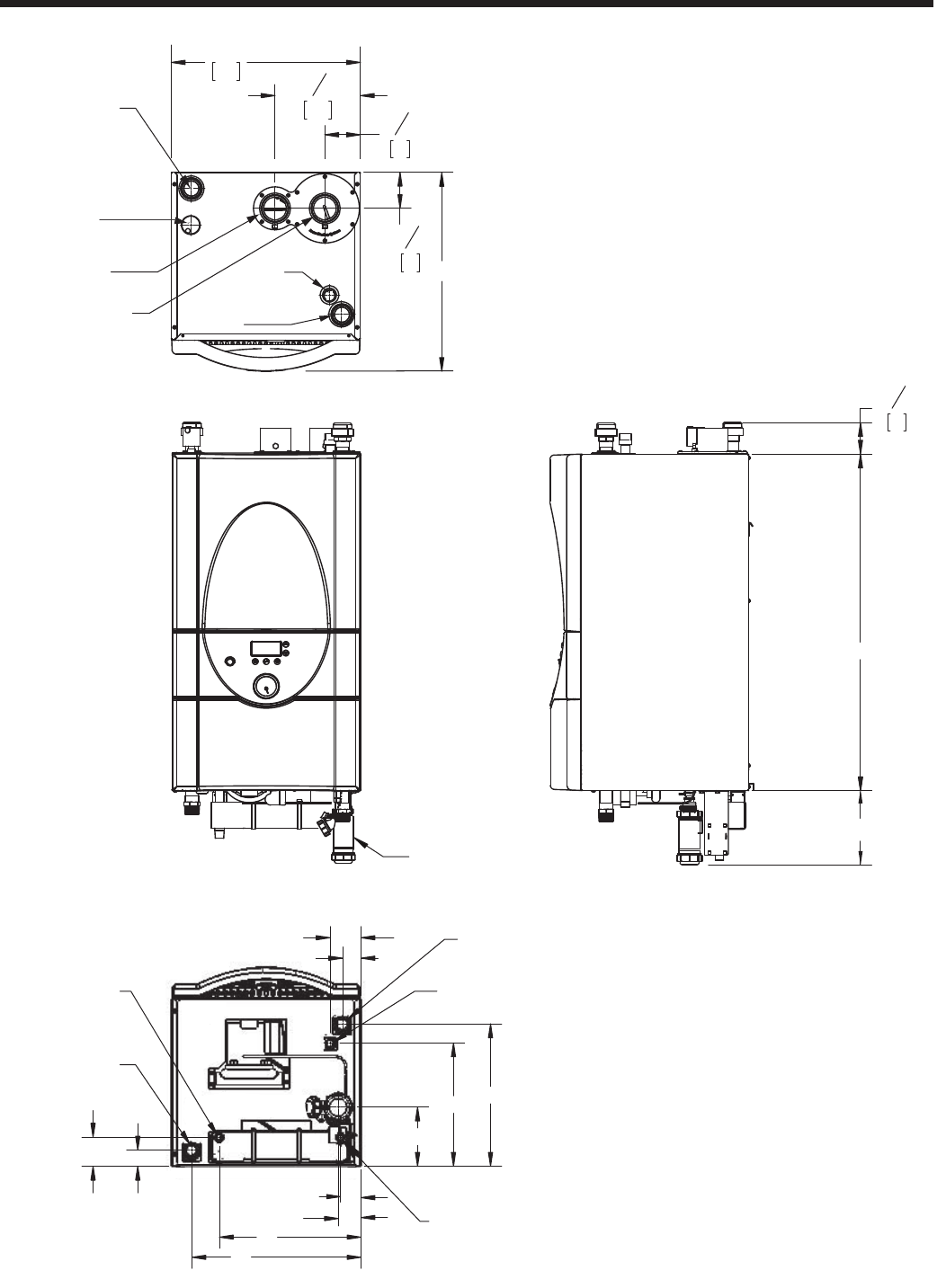
1.7 Dimensions, Brute LX
Figure 5. Dimensional Drawing, All Sizes

Page 5
Brute LX
Table 1. Dimensional Tables, All Sizes
Table 2. Piping Type and Sizes
Dimension
Model A B C D E F G H J*K L M N O
50, 75 MBH
1" (3) 15-3/4" (40) 3-3/4" (9) 9-1/4" (24) 8" (20) 1-1/2" (4) 5-3/4" (14) 15-1/2" (39) -- -- -- 30-1/2" (78) 15-1/4"
(39)
4-5/8" (12)
100 MBH
1" (3) 15-1/2" (39) 1-1/4" (3) 12-3/4" (33) 11" (28) 1-1/4" (3) 9-1/2" (24) 14-3/4" (37) -- -- -- 30-1/2" (78) 18" (46) 4-5/8" (12)
125 MBH
1" (3) 15-1/2" (39) 1-1/4" (3) 12-3/4" (33) 11" (28) 1-1/4" (3) 9-1/2" (24) 14-3/4" (37) 2-3/4" (7) 12-3/4" (33) 2" (5) 30-1/2" (78) 18" (46) 4-5/8" (12)
150, 175 MBH
1-1/2" (4) 15-1/4" (39) 1-3/4" (4) 13" (33) 11-1/4" (28) 2-3/4" (7) 5-1/4" (14) 2" (5) 2-3/4" (7) 12-3/4" (33) 1-3/4" (5) 35-1/2" (90) 18" (46) 8-7/8" (23)
220 MBH
1-1/2" (4) 15-1/4" (39) 1-3/4" (4) 13" (33) 11-1/4" (28) 2-3/4" (7) 5-1/4" (14) 2" (5) -- -- -- 38-1/2" (90) 18" (46) 8-7/8" (23)
Dimension
Model A B C D E F G H J*K L M N O
50, 75 MBH 1" (3) 15-3/4" (40) 3-3/4" (9) 9-1/4" (24) 8" (20) 1-1/2" (4) 5-3/4" (14) 15-1/2" (39)
-- -- -- 30-1/2" (78) 15-1/4"
(39)
4-5/8" (12)
100 MBH 1" (3) 15-1/2" (39) 1-1/4" (3) 12-3/4" (33) 11" (28) 1-1/4" (3) 9-1/2" (24) 14-3/4" (37)
-- -- -- 30-1/2" (78) 18" (46) 4-5/8" (12)
125 MBH 1" (3) 15-1/2" (39) 1-1/4" (3) 12-3/4" (33) 11" (28) 1-1/4" (3) 9-1/2" (24) 14-3/4" (37)
2-3/4" (7) 12-3/4" (33) 2" (5) 30-1/2" (78) 18" (46) 4-5/8" (12)
150, 175 MBH 1-1/2" (4) 15-1/4" (39) 1-3/4" (4) 13" (33) 11-1/4" (28) 2-3/4" (7) 5-1/4" (14) 2" (5)
2-3/4" (7) 12-3/4" (33) 1-3/4" (5) 35-1/2" (90) 18" (46) 8-7/8" (23)
220 MBH 1-1/2" (4) 15-1/4" (39) 1-3/4" (4) 13" (33) 11-1/4" (28) 2-3/4" (7) 5-1/4" (14) 2" (5)
-- -- -- 38-1/2" (90) 18" (46) 8-7/8" (23)
* - J dimension applies for both the DHW OUTLET and DHW INLET
inches (cm's)
inches (cm's)
Size
Size
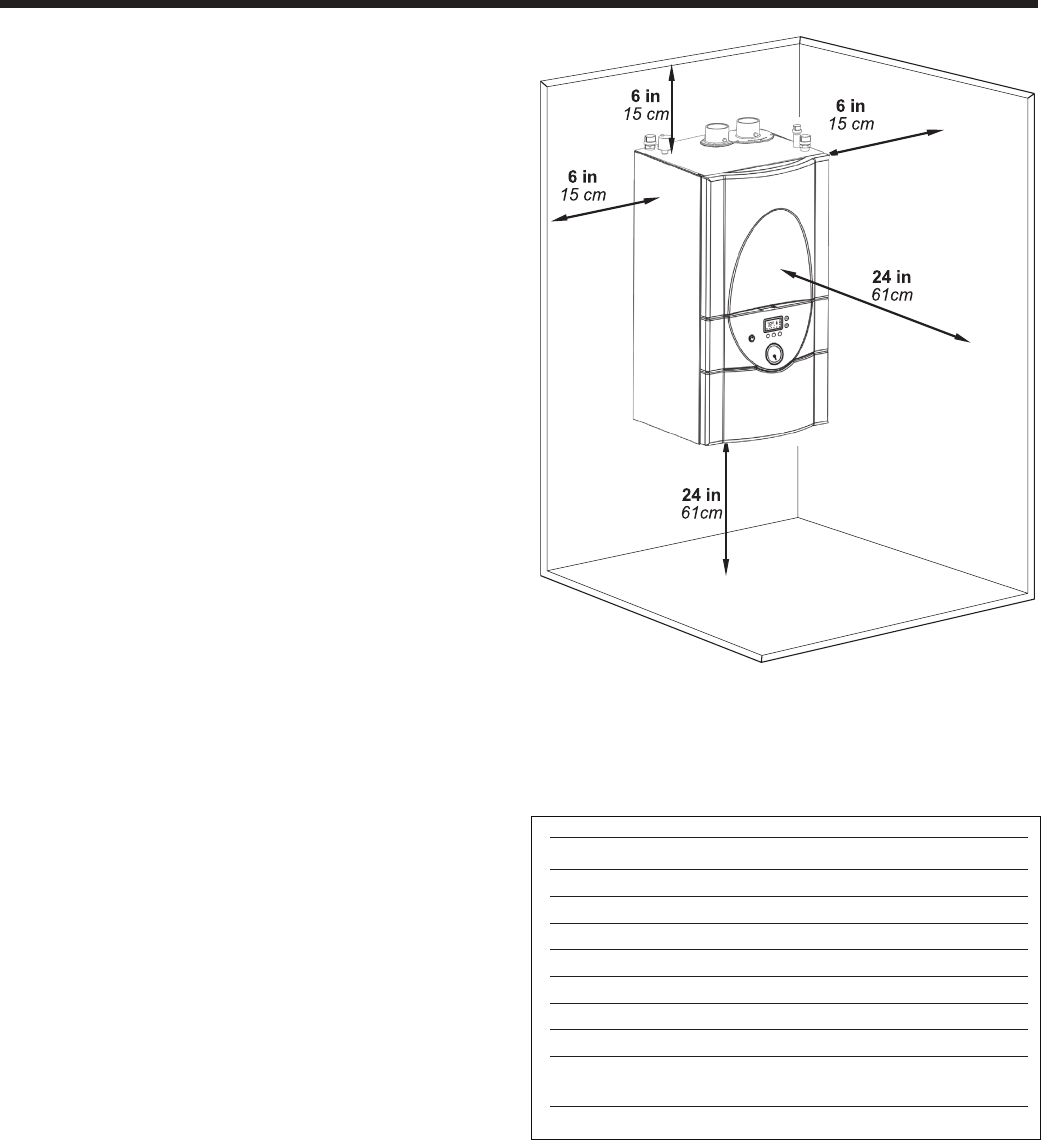
APPLIANCE SUGGESTED SERVICE ACCESS CLEARANCE
SURFACE INCHES CM
Left Side 6 15
Right Side 6 15
Top 12 30
Closet, Front 6 15
Front 24 61
Bottom 24 61
Vent 1 3
Certi ed by CSA for zero clearance to
combustible materials on all sides.
APPLIANCE SUGGESTED SERVICE ACCESS CLEARANCE
SURFACE INCHES CM
Left Side 6 15
Right Side 6 15
Top 12 30
Closet, Front 6 15
Front 24 61
Vent 1 3
Certi ed by CSA for zero clearance to
combustible materials on all sides.
Clearances
Wall Floor
Sizing Data WALL
Sizing Data FLOOR STANDING
Sizing Data,
Piping
Input Output DHW AFUE Gas Water DHW Shipping
Model Output @ Conn. Size Conn. Size Conn. Size Weight
BTU/h kW BTU/h kW 75°F Rise inches inches inches lbs kg
MLX 50 50,000 14.6 47,500 13.2 - 95% 1/2” NPT 3/4” NPT - 88 40
MLX 75 75,000 21.9 71,250 20.8 - 95% 1/2” NPT 3/4” NPT - 97 44
MLX 100 100,000 29.3 95,000 27.8 - 95% 1/2” NPT 3/4” NPT - 112 51
MLX 125 125,000 36.6 118,750 34.8 3.1 gpm 95% 1/2” NPT 3/4” NPT 1/2” NPT 126 57
MLX 150 150,000 43.9 142,500 41.8 3.7 gpm 95% 1/2” NPT 1“ NPT 1/2” NPT 140 64
MLX 175 175,000 51.6 166,250 48.7 4.3 gpm 95% 1/2” NPT 1“ NPT 1/2” NPT 153 69
MLX 220 220,000 64.4 209,000 61.2 - 95% 1/2” NPT 1“ NPT - 161 73
Input Output DHW AFUE Gas Water DHW Shipping
Model Output @ Conn. Size Conn. Size Conn. Size Weight
BTU/h kW BTU/h kW 75°F Rise inches inches inches lbs kg
MLX 50 50,000 14.6 47,500 13.2 - 95% 1/2” NPT 3/4” NPT - 144 65
MLX 75 75,000 21.9 71,250 20.8 - 95% 1/2” NPT 3/4” NPT - 151 68
MLX 100 100,000 29.3 95,000 27.8 - 95% 1/2” NPT 3/4” NPT - 166 75
MLX 125 125,000 36.6 118,750 34.8 3.1 gpm 95% 1/2” NPT 3/4” NPT 1/2” NPT 178 81
MLX 150 150,000 43.9 142,500 41.8 3.7 gpm 95% 1/2” NPT 1“ NPT 1/2” NPT 184 83
MLX 175 175,000 51.6 166,250 48.7 4.3 gpm 95% 1/2” NPT 1“ NPT 1/2” NPT 192 87
MLX 220 220,000 64.4 209,000 61.2 - 95% 1/2” NPT 1“ NPT - 201 91
NOTES:
1. For other boiler ratings:
Boiler Horsepower: HP = Output Radiation Surface: EDR sq. ft. = Output
33,475 150
NOTES:
1. For other boiler ratings:
Boiler Horsepower: HP = Output Radiation Surface: EDR sq. ft. = Output
33,475 150
50 thru 125
150 - 220
Cond. Hydronic DHW 2nd Gas Hydronic DHW 2nd
Outlet Return Inlet Return Supply Supply Outlet Supply
3/4" 3/4" 1/2" 3/4" 1/2" 3/4" 1/2" 3/4"
PVC copper NPT copper NPT NPT NPT copper
3/4" 1" 1/2" 3/4" 1/2" 1" 1/2" 3/4"
PVC NPT NPT copper NPT NPT NPT copper
Shipping
Weight
lbs kg
- -
- -
- -
133 60
148 67
163 74
- -
Shipping
Weight
lbs kg
- -
- -
- -
188 85
194 88
202 92
- -
CombiBoiler
Size
Page 6
BRADFORD WHITE CORP
.
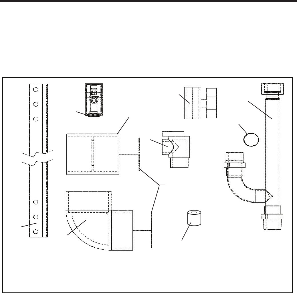
Figure 6. Contents of the Hardware Shipping Package
Some accessory items may be shipped in separate
packages. Verify receipt of all packages listed on the
packing slip. Inspect everything for damage immediately
upon delivery, and advise the carrier of any shortages
or damage. Any such claims must be led with the
carrier. The carrier, not the shipper, is responsible
for shortages and damage to the shipment whether
visible or concealed.
1.8 Unpacking
The Brute LX is shipped in a single crate with the
standard components packed with the appliance See
Figure 6:
1. Remove all packing and tie-down materials.
2. Check contents of the carton against items shown.
1) PRV
2) PRV Pipe w/ washer
3) Wall attach bracket
1
2
7
4
3
69
5
8
4) Outdoor sensor
5) Exhaust terminal assy
6) Air intake terminal assy
7) Gas Supply Shut Off Valve
8) Washer
9) Flow restrictor
1.9 Warranty
Bradford White Brute LX appliances are covered by
a limited warranty. The owner should complete the
warranty registration at www.bradfordwhite.com.
All warranty claims must be made to an authorized
Bradford White representative. Claims must include the
serial number and model (this information can be found
on the rating plate), installation date, and name of the
installer. Shipping costs are not included in the warranty
coverage.
Bird Screen
Page 7
Brute LX
SECTION 2.
Locating the Appliance
2.1 Locating the Appliance
The Brute LX is designed for indoor
wall-mounted installations only.
The Brute LX must be mounted to a suitable wall by a
qualied heating contractor under the guidelines of a
wall mounted boiler or combination unit. Use a suitable
wall, either concrete or wood and use the appropriate
fasteners for that wall. Failure to wall mount this boiler
using correct fasteners will affect the performance and
life expectancy of the boiler and will void the warranty.
The appliance should be located to provide clearances
on all sides for maintenance and inspection. It should
not be located in an area where leakage of any
connections will result in damage to the area adjacent to
the appliance, the wall that it is hung on, or to the lower
oors of the structure.
When such a location is not available, it is recommended
that a suitable drain pan, adequately drained, be installed
under the appliance.
The appliance is design certied by CSA-International
for wall-mounted installation in basements; in closets,
utility rooms or alcoves. The location for the appliance
should be chosen with regard to the vent pipe lengths
and external plumbing and on a plumb (vertical) wall.
The unit shall be installed such that the gas ignition
system components are protected from water (dripping,
spraying, rain, etc.) during operation and service
(circulator replacement, control replacement, etc.).
If the vent terminal and/or combustion air terminal
terminate through a wall, and there is potential for snow
accumulation in the local area, both terminals must
be installed at an appropriate level above grade or the
maximum expected snow line.
The dimensions and requirements that are shown in
Table 3 should be met when choosing the locations for
the appliance.
2.2 Correct Vent Distance from Outside
Wall or Roof Termination
The forced draft combustion air blower in the appliance
has sufcient power to vent properly when the
guidelines in Table 4 are followed.
For concentric vent terminal kit (optional), follow
installation instructions included with the kit.
NOTE: When located on the same wall, the Minimum
Venting Distance is found on Figure 11.
Figure 7. Locating the Appliance.
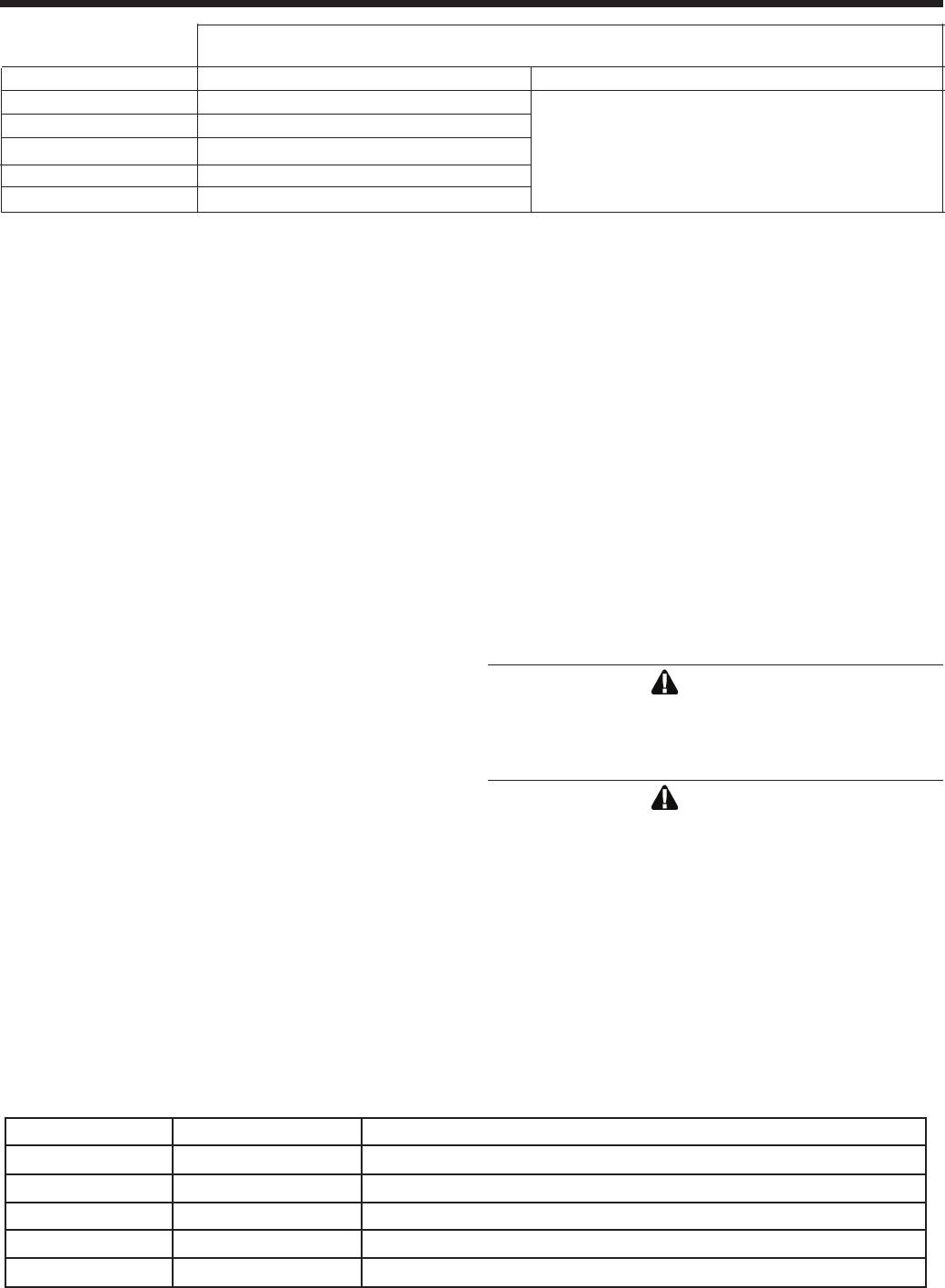
Table 3. Clearances
APPLIANCE SUGGESTED SERVICE ACCESS CLEARANCE
SURFACE INCHES CM
Left Side 6 15
Right Side 6 15
Top 12 30
Closet, Front 6 15
Front 24 61
Bottom 24 61
Vent 1 3
Certi ed by CSA for zero clearance to
combustible materials on all sides.
APPLIANCE SUGGESTED SERVICE ACCESS CLEARANCE
SURFACE INCHES CM
Left Side 6 15
Right Side 6 15
Top 12 30
Closet, Front 6 15
Front 24 61
Vent 1 3
Certi ed by CSA for zero clearance to
combustible materials on all sides.
Clearances
Wall Floor
Sizing Data WALL
Sizing Data FLOOR STANDING
Sizing Data,
Piping
Input Output DHW AFUE Gas Water DHW Shipping
Model Output @ Conn. Size Conn. Size Conn. Size Weight
BTU/h kW BTU/h kW 75°F Rise inches inches inches lbs kg
MLX 50 50,000 14.6 47,500 13.2 - 95% 1/2” NPT 3/4” NPT - 88 40
MLX 75 75,000 21.9 71,250 20.8 - 95% 1/2” NPT 3/4” NPT - 97 44
MLX 100 100,000 29.3 95,000 27.8 - 95% 1/2” NPT 3/4” NPT - 112 51
MLX 125 125,000 36.6 118,750 34.8 3.1 gpm 95% 1/2” NPT 3/4” NPT 1/2” NPT 126 57
MLX 150 150,000 43.9 142,500 41.8 3.7 gpm 95% 1/2” NPT 1“ NPT 1/2” NPT 140 64
MLX 175 175,000 51.6 166,250 48.7 4.3 gpm 95% 1/2” NPT 1“ NPT 1/2” NPT 153 69
MLX 220 220,000 64.4 209,000 61.2 - 95% 1/2” NPT 1“ NPT - 161 73
Input Output DHW AFUE Gas Water DHW Shipping
Model Output @ Conn. Size Conn. Size Conn. Size Weight
BTU/h kW BTU/h kW 75°F Rise inches inches inches lbs kg
MLX 50 50,000 14.6 47,500 13.2 - 95% 1/2” NPT 3/4” NPT - 144 65
MLX 75 75,000 21.9 71,250 20.8 - 95% 1/2” NPT 3/4” NPT - 151 68
MLX 100 100,000 29.3 95,000 27.8 - 95% 1/2” NPT 3/4” NPT - 166 75
MLX 125 125,000 36.6 118,750 34.8 3.1 gpm 95% 1/2” NPT 3/4” NPT 1/2” NPT 178 81
MLX 150 150,000 43.9 142,500 41.8 3.7 gpm 95% 1/2” NPT 1“ NPT 1/2” NPT 184 83
MLX 175 175,000 51.6 166,250 48.7 4.3 gpm 95% 1/2” NPT 1“ NPT 1/2” NPT 192 87
MLX 220 220,000 64.4 209,000 61.2 - 95% 1/2” NPT 1“ NPT - 201 91
NOTES:
1. For other boiler ratings:
Boiler Horsepower: HP = Output Radiation Surface: EDR sq. ft. = Output
33,475 150
NOTES:
1. For other boiler ratings:
Boiler Horsepower: HP = Output Radiation Surface: EDR sq. ft. = Output
33,475 150
50 thru 125
150 - 220
Cond. Hydronic DHW 2nd Gas Hydronic DHW 2nd
Outlet Return Inlet Return Supply Supply Outlet Supply
3/4" 3/4" 1/2" 3/4" 1/2" 3/4" 1/2" 3/4"
PVC copper NPT copper NPT NPT NPT copper
3/4" 1" 1/2" 3/4" 1/2" 1" 1/2" 3/4"
PVC NPT NPT copper NPT NPT NPT copper
Shipping
Weight
lbs kg
- -
- -
- -
133 60
148 67
163 74
- -
Shipping
Weight
lbs kg
- -
- -
- -
188 85
194 88
202 92
- -
CombiBoiler
Page 8
BRADFORD WHITE CORP
.
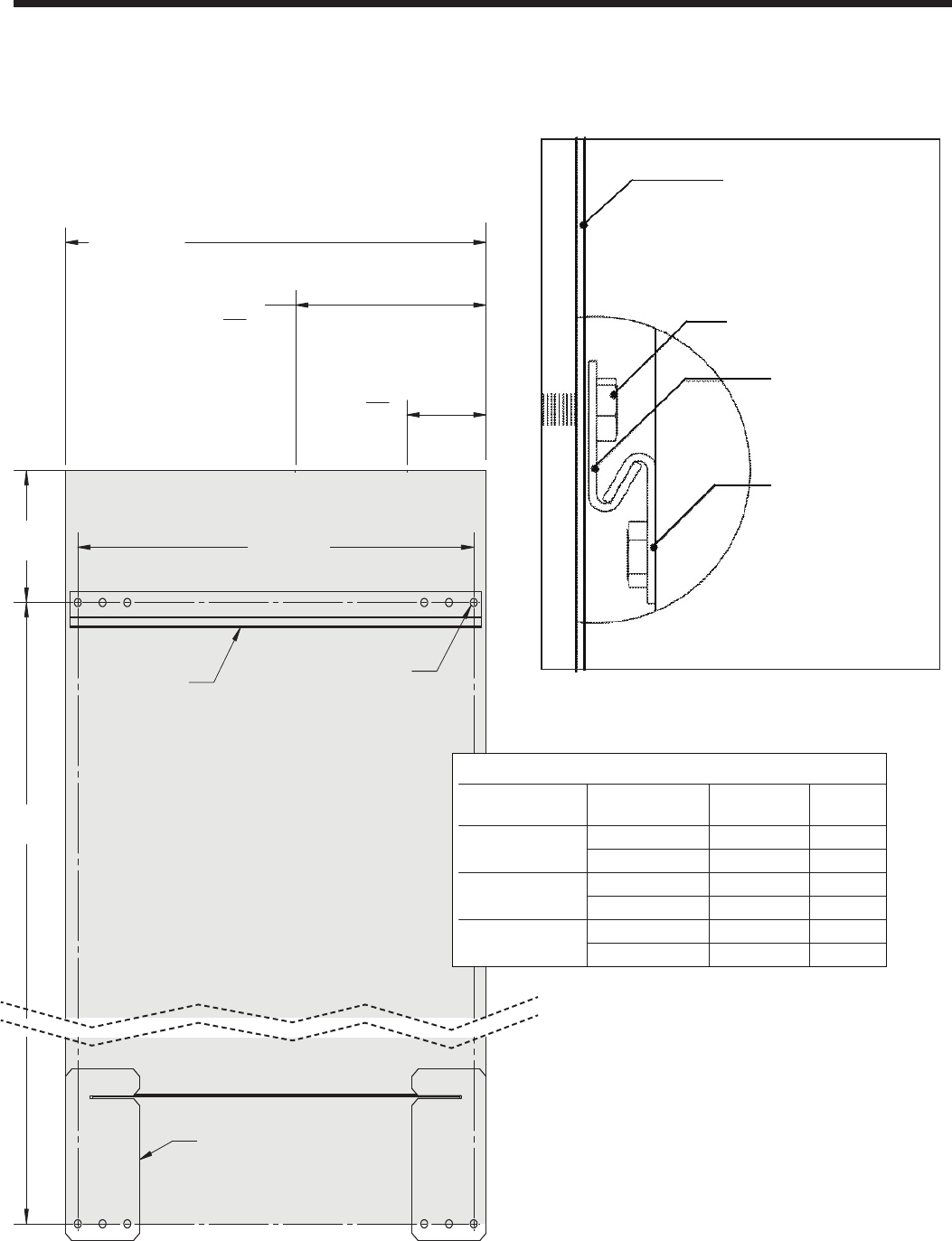
Figure 8. Mounting Detail.
Note: Brute LX
bracket and wall
bracket are
purposely offset.
Bracket factory-
mounted
on back of Mascot
Wall bracket
provided by
Bradford White
Wall to which Brute
LX is mounted
Anchor / fastener provided
by Installer - appropriate for
250 lbs (114 kg) operating
weight
Figure 9. Wall Bracket Hole Mounting Locations
B366 0
A4-1/2 11.5
B29- 3/4 75.7
A5-
B33-685.2
A 54 14.7
DIMENSIONS
MASCOT LX
MODEL SIZEDESIGNATOR INCHES CM
50, 75, 100, 125
150/175
220
SH
1
MANUAL, MASCOT LX
H23686
D
C
B
A
B
C
D
1
2
H23686
THIRD ANGLE PROJECTION.
PROPRIETARY TO LAARS HEATING SYSTEMS AND SHALL NOT BE
1/8"
WAS 1:1 SCALE WALL TEMPLATE, NOW GRAPHICS FOR
3
4
4
APPR
2
BY LAARS HEATING SYSTEMS.
FMA56A
.1
DECIMALS .XX
3
1
REV
A
CD 5-12-14
REVISIONS
REV.
CHANGE:
CD 4-24-14
TOLERANCES ARE:
FINISH
NONE
PURPOSE EXCEPT AS SPECIFICALLY AUTHORIZED IN WRITING
USE IN I/O MANUAL
A
14-034N JM 5-12-14
DECIMALS .X
INTENDED SIZE: SOFTWARE DWG. NO:
C
SHEET 1 OF 1
REV.
DWG NO.
.03
DECIMALS .XXX
TITLE:
REPRODUCED, TRANSFERRED TO OTHER DOCUMENTS, USED OR
.010
SCALE: NONE
MATERIAL:
DISCLOSED TO OTHERS FOR MANUFACTURING OR ANY OTHER
DIMENSIONS ARE IN INCHES.
APPROVALS
ENGR APPR
ECN
NONE
DRAFT
ENGR
DRAFT
JM 4-24-14
S
CHECK
APPR
UNLESS OTHERWISE SPECIFIED:
DO NOT SCALE DRAWING.
THIS DOCUMENT AND THE INFORMATION CONTAINED HEREIN ARE
ANGLES
FRACTIONS
WALL TEMPLATE, I/O
A
Safety Wall Bracket, Qty 2
(supplied)
12P4010
Dimensions shown in Inches and centimeters
3 4
8.1 cm
40.6 cm
16”
A
Concentric
"
1
43.2 cm
17 "
B
Overall Width
2" Exhaust and
2" Air Inlet
19.6 cm
7 3
4 "
Bolts/Anchors (4)
provided by installer,
each is to be suitable for
160 lbs [73kg]
minimum.
Centered
Wall Bracket
(supplied)
12P3013
Wall Mounting Dimensions
Zero clearance to combustables allowed
Recommended service clearances:
Sides: 3" / 15cm
Top 6" / 15cm
Bottom: 24" / 61cm
Front: 24" / 61cm
11.5
75.6
13.4
85.2
14.6
93.0
B
A
Desired top of Brute LX
B366 0
A4-1/2 11.5
B29- 3/4 75.7
A5-
B33-685.2
A 54 14.7
DIMENSIONS
MASCOT LX
MODEL SIZEDESIGNATOR INCHES CM
50, 75, 100, 125
150/175
220
SH
1
MANUAL, MASCOT LX
H23686
D
C
B
A
B
C
D
1
2
H23686
THIRD ANGLE PROJECTION.
PROPRIETARY TO LAARS HEATING SYSTEMS AND SHALL NOT BE
1/8"
WAS 1:1 SCALE WALL TEMPLATE, NOW GRAPHICS FOR
3
4
4
APPR
2
BY LAARS HEATING SYSTEMS.
FMA56A
.1
DECIMALS .XX
3
1
REV
A
CD 5-12-14
REVISIONS
REV.
CHANGE:
CD 4-24-14
TOLERANCES ARE:
FINISH
NONE
PURPOSE EXCEPT AS SPECIFICALLY AUTHORIZED IN WRITING
USE IN I/O MANUAL
A14-034N JM 5-12-14
DECIMALS .X
INTENDED SIZE: SOFTWARE DWG. NO:
C
SHEET 1 OF 1
REV.
DWG NO.
.03
DECIMALS .XXX
TITLE:
REPRODUCED, TRANSFERRED TO OTHER DOCUMENTS, USED OR
.010
SCALE: NONE
MATERIAL:
DISCLOSED TO OTHERS FOR MANUFACTURING OR ANY OTHER
DIMENSIONS ARE IN INCHES.
APPROVALS
ENGR APPR
ECN
NONE
DRAFT
ENGR
DRAFT
JM 4-24-14
S
CHECK
APPR
UNLESS OTHERWISE SPECIFIED:
DO NOT SCALE DRAWING.
THIS DOCUMENT AND THE INFORMATION CONTAINED HEREIN ARE
ANGLES
FRACTIONS
WALL TEMPLATE, I/O
A
Safety Wall Bracket, Qty 2
(supplied)
12P4010
Dimensions shown in Inches and centimeters
3 4
8.1 cm
40.6 cm
16”
A
Concentric
"
1
43.2 cm
17 "
B
Overall Width
2" Exhaust and
2" Air Inlet
19.6 cm
7 3
4 "
Bolts/Anchors (4)
provided by installer,
each is to be suitable for
160 lbs [73kg]
minimum.
Centered
Wall Bracket
(supplied)
12P3013
Wall Mounting Dimensions
Zero clearance to combustables allowed
Recommended service clearances:
Sides: 3" / 15cm
Top 6" / 15cm
Bottom: 24" / 61cm
Front: 24" / 61cm
11.5
75.6
13.4
85.2
14.6
93.0
2.2 Wall Mount Hole Locations.
5-1/4
33-1/2
5-3/4
36-1/2

Page 9
Brute LX
Table 4. Vent / Air Pipe Sizes
Vent System
Vent System
INTAKE / EXHAUST
Max Equivalent
*
Vent and Air Pipe Length (each)
STANDARD OPTIONAL
Size 2" dia 5.1cm 3"/5" dia 7.6/12.7cm
125 40 ft 12.2m 40 ft 12.2m
Installations in the U.S. require exhaust vent pipe that is PVC or CPVC complying
with ANSI/ASTM D1785 F441 or stainless steel complying with UL1738. Laars
supplies the rst section of vent pipe which is 16" of CPVC with each boiler. Installa-
tions in Canada require exhaust vent pipe that is certi ed to ULC S636.
Intake (air) pipe may be PVC, CPVC, ABS or galvanized pipe.
*
To calculate equivalent length, measure the linear feet of the pipe, and add 5 feet
(1.5m) for each elbow used.
INTAKE AND EXHAUST LENGTH
MAX EQUIV. MAX EQUIV. CONCENTRIC MAX EQUIV.
SIZE VENT FT. M VENT FT. M VENT FT. M
50 2" 40 6.1 *3"* 150 30.5 3/5" 40 6.1
75 2" 40 6.1 *3"* 150 30.5 3/5" 40 6.1
100 2" 40 6.1 *3"* 150 30.5 3/5" 40 6.1
125 2" 40 6.1 *3"* 150 30.5 3/5" 40 6.1
150 2" 40 6.1 *3"* 150 30.5 3/5" 40 6.1
175 2" 40 6.1 *3"* 150 30.5 3/5" 40 6.1
220 2" 30 4.6 *3"* 120 24.4 3/5" 40 6.1
INTAKE / EXHAUST
Max Equivalent Vent and Air Pipe Length (each)
STANDARD 2-PIPE STANDARD 2-PIPE OPTIONAL CONCENTRIC
SIZES DIA. FT. m DIA. FT. m DIA. FT. m
50 - 175 2" 40 12.2 *3"* 150 45.7 3/5" 40 12.2
220 2” 30 9.1 *3”* 120 36.6 3/5” 40 12.2
Installations in the U.S. require exhaust vent pipe that is a combination of PVC & CPVC complying with
ANSI/ASTM D1785 F441 or stainless steel complying with UL1738. Polypropylene installations require
exhaust vent pipe that is certi ed to ULC S636.
Intake (air) pipe may be any material that complies with ANSI/ASTM D1785 F441, ABS that complies with
ANSI/ASTM D1527 or galvanized material.
Installer must comply fully with manufacturer's installation instructions, to maintain ANSI Z21.13 safety
certi cation.
Closet and alcove installations do not allow the use of PVC under any circumstances
To calculate max equivalent length, measure the linear feet of the pipe, and add 5 feet (1.5m) for each
elbow used.
* Must use 2x3 adapter within 1 ft. (30cm) of boiler.
Electrical
Data
Size Boiler
Volts Phase Amps
MLX 50 120 Single 1.5
MLX 75 120 Single 1.5
MLX 100 120 Single 1.5
MLX 125 120 Single 1.5
MLX 150 120 Single 1.5
MLX 175 120 Single 2.2
MLX 220 120 Single 2.2
*
Minimum 15A circuit required
* Must use 2x3 adapter within 1 ft. (30cm) of boiler.
Reference the Installation and Operation Manual for more details.
SECTION 3.
Venting and Combustion Air
The Brute LX includes a standard CPVC vent/combustion
air adapter. If eld connections require use of PVC/CPVC
vent materials, the installer must use proper adhesive to
join CPVC and/or PVC pipe and ttings.
3.1 Combustion Air
Brute LX boilers and water heaters must have provisions
for combustion and ventilation air in accordance with the
applicable requirements for Combustion Air Supply and
Ventilation in the National Fuel Gas Code, ANSI Z223
1; or in Canada, the Natural Gas and Propane Installation
Code, CSA B149.1. All applicable provisions of local
building codes must also be adhered to.
A Brute LX unit can take combustion air from the
space in which it is installed, or the combustion air
can be ducted directly to the unit. Ventilation air must
be provided in either case.
3.1.1 Combustion Air from Room
In the United States, the most common requirements
specify that the space shall communicate with the
outdoors in accordance with method 1 or 2, which follow.
Where ducts are used, they shall be of the same cross-
sectional area as the free area of the openings to which
they connect.
Method 1: Two permanent openings, one commencing
within 12" (300mm) of the top and one commencing
within 12" (300mm) of the bottom, of the enclosure
shall be provided. The openings shall communicate
directly, or by ducts, with the outdoors or spaces
that freely communicate with the outdoors. When
directly communicating with the outdoors, or when
communicating to the outdoors through vertical ducts,
each opening shall have a minimum free area of 1
square inch per 4000 Btu/hr (550 square mm/kW) of
total input rating of all equipment in the enclosure.
When communicating to the outdoors through
horizontal ducts, each opening shall have a minimum
free area of not less than 1 square inch per 2000 Btu/
hr (1100 square mm/kW) of total input rating of all
equipment in the enclosure.
Method 2: One permanent opening, commencing
within 12" (300mm) of the top of the enclosure, shall
be permitted. The opening shall directly communicate
with the outdoors or shall communicate through a
vertical or horizontal duct to the outdoors or spaces
that directly communicate with the outdoors and shall
have a minimum free area of 1 square inch per 3000
Page 10
BRADFORD WHITE CORP
.
The ue temperature of the Brute LX changes
dramatically with changes in operating water
temperature. Therefore, it is necessary to assess the
application of the boiler to determine the required
certied vent class. If the Brute LX is installed in
an application where the ambient temperature is
elevated, and/or installed in a closet/alcove, CPVC,
polypropylene, or stainless steel material is required.
If the system temperatures are unknown at the time
of installation, stainless, polypropylene or CPVC
material is recommended.
The Brute LX is a Category IV appliance and may
be installed with PVC, CPVC or polypropylene that
complies with ULC-S636, ANSI/ASTM D1785 F441
(see Table 4) or a stainless steel venting system that
complies with UL 1738 Standard (see Table 8).
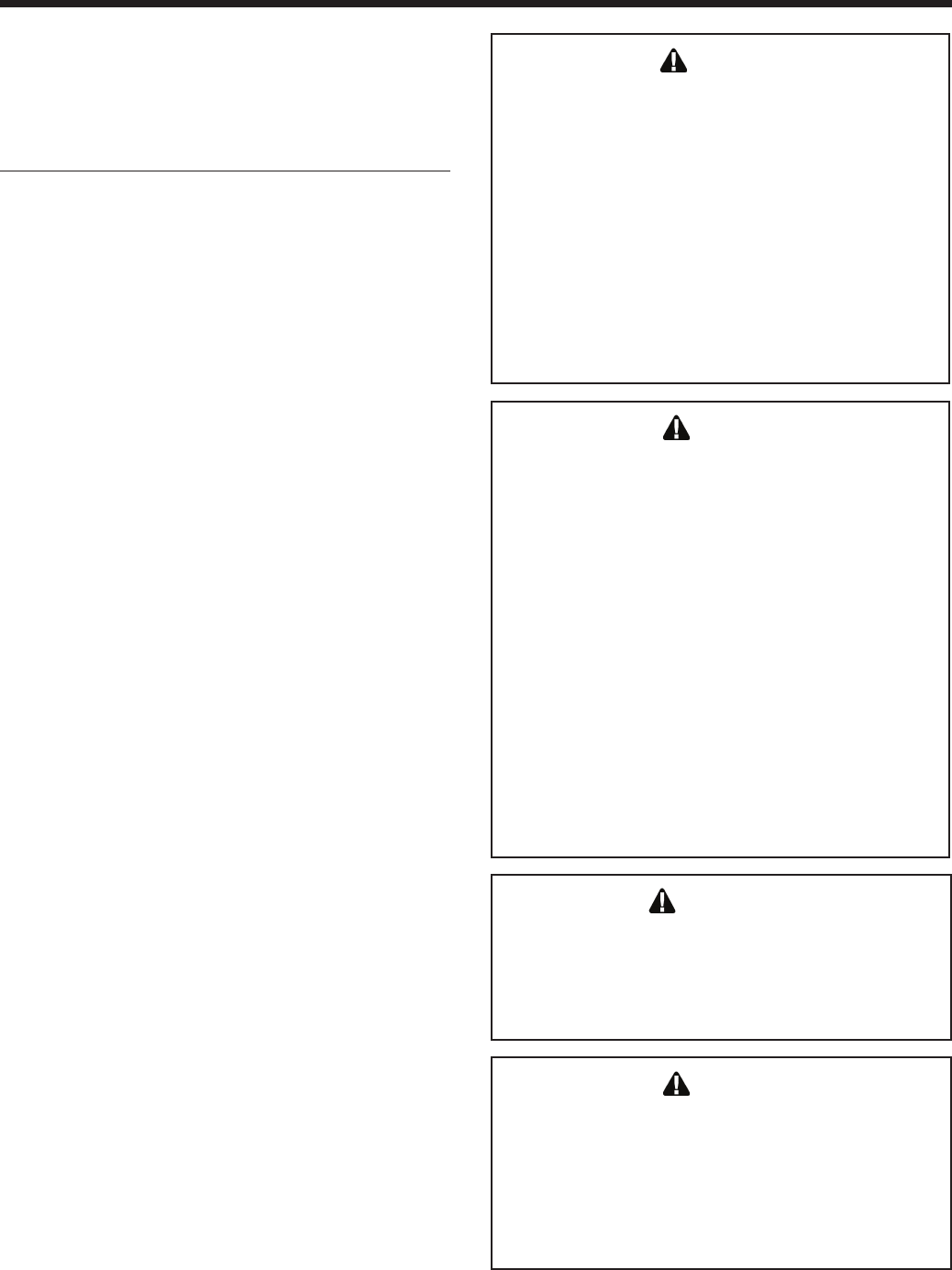
WARNING
Failure to use the appropriate vent material, installation
techniques, glues/sealants could lead to vent failure
causing property damage, personal injury or death.
WARNING
Btu/hr (734 square mm/kW) of the total input rating of
all equipment located in the enclosure. This opening
must not be less than the sum of the areas of all vent
connectors in the conned space.
Other methods of introducing combustion and
ventilation air are acceptable, providing they conform to
the requirements in the applicable codes listed above.
In Canada, consult local building and safety codes or, in
absence of such requirements, follow CAN/CGA B149.
3.1.2 Ducted Combustion Air
The combustion air can be taken through the wall, or
through the roof. When taken from the wall, it must be
taken from out-of-doors by means of the Bradford White
horizontal wall terminal, shown in Table 5. See Table 4
to select the appropriate diameter air pipe. When taken
from the roof, a eld-supplied rain cap or an elbow
arrangement must be used to prevent entry of rain water
(see Figure 5).
Use ABS, PVC, CPVC, polypropylene, or galvanized
pipe for the combustion air intake (see Table 6), sized
per Table 4. Route the intake to the boiler as directly
as possible. Seal all joints. Provide adequate hangers.
The unit must not support the weight of the combustion
air intake pipe. Maximum linear pipe length allowed is
shown in Table 4. Subtract 5 allowable linear ft. (1.5m)
for every elbow used.
The connection for the intake air pipe is at the top of the
unit (see Figure 3).
In addition to air needed for combustion, air shall also
be supplied for ventilation, including air required for
comfort and proper working conditions for personnel.
3.2 Venting (Exhaust)
Table 5. Vent Termination Options
Part Number Size Description
239-44069-02 2" PVC Concentric Vent Terminal
239-44069-01 3" PVC Concentric Vent Terminal
CA010101 2" Flush Vent Terminal PVC
CA010100 3" Flush Vent Terminal PVC
CA007100 3" to 5" Stainless Steel Concentric Vent Terminal
INSTALLATION STANDARDS
MATERIAL UNITED STATES CANADA
ABS ANSI/ASTM D1527
PVC, sch 40 ANSI/ASTM D1785 or D2665 Air pipe material must be chosen
CPVC, sch 40 ANSI/ASTM F441 CPVC, sch 40, ANSI/ASTM, Polypropylene
Polypropylene UL1738, ULC S636. based upon the intended application of the boiler.
Single wall galv. steel 26 gauge
Table 6. Required Combustion Air Pipe Material.
Page 11
Brute LX
NOTICE
For Category II and IV boilers, be installed so as to
prevent accumulation of condensate; and
For Category II and IV boilers, where necessary,
have means provided for drainage of condensate.
AVIS
les chaudières de catégories II et IV doivent être
installées de façon à empêcher l'accumulation de
condensat; et
si nécessaire, les chaudières de catégories II et IV
doivent être pourvues de dispositifs d'évacuation du
condensat.
NOTICE
The instructions for the installation of the venting
system shall specify that the horizontal portions of
the venting system shall be supported to prevent
sagging; the methods of and intervals for support
shall be specied. These instructions shall also
specify that the venting system:
Category I, II and IV boilers must be installed so
that horizontal sections have a slope of at least ¼
inch per foot (21 mm/m) to prevent accumulation of
condensate; and
For Category II and IV boilers, where necessary,
have means provided for drainage of condensate.
AVIS
Les instructions d'installation du système
d'évacuation doivent préciser que les sections
horizontales doivent être supportées pour prévenir
le échissement. Les méthodes et les intervalles
de support doivent être spéciés. Les instructions
doivent aussi indiquer les renseignements suivants:
les chaudières de catégories I, II et IV doivent
présenter des tronçons horizontaux dont la pente
montante est d'au moins ¼ po par pied (21 mm/m)
entre la chaudière et l'évent; les chaudières de
catégories II et IV doivent être installées de façon à
empêcher l'accumulation de condensat;
et si nécessaire, les chaudières de catégories II et IV
doivent être pourvues de dispositifs d'évacuation du
condensat.
All venting must be installed according to this manual
and any other applicable local codes, including but
not limited to, ANSI Z223.1/NFPA 54, CSA B149.1,
CSAB149.2 and ULC-S636. Failure to follow this
manual and applicable codes may lead to property
damage, severe injury, or death.
INSTALLATIONS IN CANADA require the use
of venting material certied to ULCS636. All Gas
vents connected to the Brute LX, plastic, stainless
steel or otherwise must be certied to this ULC
standard. Appropriate selection of vent material is
very important for proper performance and safe
operation of the Brute LX.
The ue temperature of the Brute LX changes
dramatically with changes in operating water
temperature. Therefore, it is necessary to assess the
application of the boiler to determine the required
certied vent class. If the Brute LX is installed in
an application where the outlet water temperature
exceeds 145°F, and/or installed in a closet, class
IIB or higher vent material is required. If the
system temperatures are unknown at the time of
installation, class IIB or higher venting material is
recommended.
IN CANADA all venting used must meet the
following requirements:
1. ULC-S636 certied and marked
2. The rst 3 feet of venting must be accessible for
visual inspection.
3. All components used in the vent system must be
from a certied manufacturer.
4 . Vent system components must not be mixed
with alternate manufacturers certied
components and/or unlisted components.
5 . The venting must be installed according to the
vent manufacturers installation instructions.
The unit’s vent can terminate through the roof, or
through an outside wall.
See Table 4 to select the appropriate vent pipe
diameter. Vent pipe must pitch upward, toward the vent
terminal, not less than 1/4" per foot, so that condensate
will run back to the Brute LX to drain. Route vent pipe
to the heater as directly as possible. Seal all joints and
provide adequate hangers as required in the venting
system manufacturer’s Installation Instructions.
Horizontal portions of the venting system must be
supported to prevent sagging and may not have any
low sections that could trap condensate. The unit must
not support the weight of the vent pipe.
Page 12
BRADFORD WHITE CORP
.
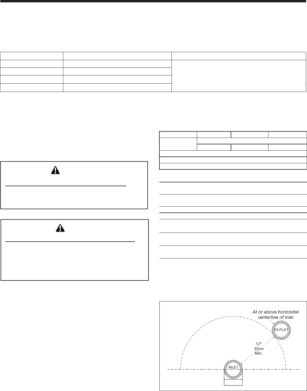
Figure 10. Minimum Venting Distance.
NOTICE
DO NOT COMMON VENT BRUTE LX UNITS.Brute
LX units are never permitted to share a vent with
Category I appliances.
AVIS
NE PAS ÉVENT COMMUNE BRUTE LX UNITÉS.
Brute LX unités ne sont jamais autorisés à
partager un évent Catégorie I avec les appareils.
3.2.1 About Common Venting
Table 7. Allowable Vent Manufacturers
INSTALLATION STANDARDS
MATERIAL UNITED STATES CANADA
Stainless Steel UL 1738 Venting must be ULC-S636 certied for use as
PVC, sch 40 ANSI/ASTM D178 venting material. The venting material must be chosen
CPVC, sch 40 ANSI/ASTM F441 based upon the intended application of the boiler.
Polypropylene UL1738 or ULC-S636
Table 8. Required Exhaust Vent Material.
Allowable Polypropylene Vent Manufacturers
/ Trade Names
MFR (model number abbreviated*)
Centrotherm DuraVent Selkirk
InnoFlue PolyPro Polyflue
Single Wall Pipe ISVLxxxx xPPS-x xPF-xx
Elbow ESELxxxx xPPS-E90 xPF-90
PVC adapter ISAGxxxx xPPS-AD xPF-PVC-PF
Notes:
Only the above manufacturers and models have been approved.
Substitutes are not allowed.
Trade Names/Models
"x", "xx" and "xxxx" refer to variations in nominal size. See manufacturer's
catalog for a particular application.
These manufacturers samples have been tested and authorized to safely
operate with Laars equpment.
Contact Polypropylene manufacturer's distributor for complete model
number selection.
Installer must follow Polypropylene manufacturers installation instructions.
Example
Components
Manufacturers materials and models may not be mixed in the same
application.
These manufacturers samples have been tested and authorized to safely
operate with Bradford White equipment
Page 13
Brute LX
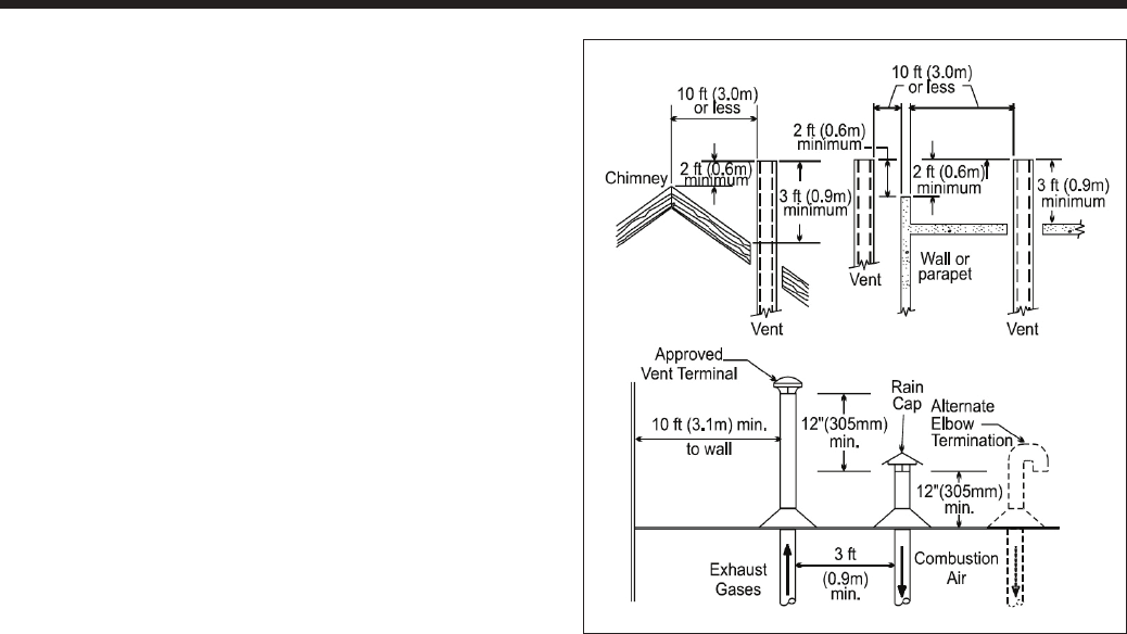
Figure 11. Combustion Air and Vent Through Roof.
issues.
3.3.2 Side Wall Combustion Air Terminal
The Bradford White side wall combustion air terminal,
or concentric terminal (see Table 5), must be used
when the heater takes air from a side wall. Consider the
following when installing the terminal (see Figure 12):
1. Do not locate the air inlet terminal near a source
of corrosive chemical fumes (e.g., cleaning uid,
chlorine compounds, etc.)
2. Locate the terminal so that it will not be subject to
damage by accident or vandalism. It must be at least
7 feet (2.1m) above a public walkway.
3. Locate the combustion air terminal so that it cannot
be blocked by snow. The National Fuel Gas Code
requires that it be at least 12 inches (30cm) above
grade, but the installer may determine it should be
higher, depending upon local conditions.
4. For concentric vent, follow instructions included
with vent kit.
5. Multiple vent kits should be installed such that the
horizontal distance between outlet group and inlet
group is 36" (90cm) minimum.
6. Vent outlet must be no lower than the center of the
air inlet, and must be at least 12" (30cm) away from
the air inlet (see Figure 10).
3.3 Locating Vent & Combustion Air
Terminals
3.3.1 Side Wall Vent Terminal
The appropriate Bradford White side wall vent
terminal must be used. The terminal must be located in
accordance with ANSI Z223.1/NFPA 54 and applicable
local codes. In Canada, the installation must be in
accordance with CSA B149.1 or .2 and local applicable
codes. Consider the following when installing the
terminal:
1. Figure 12 shows the requirements for mechanical
vent terminal clearances for the U.S. and Canada.
2. Vent terminals for condensing appliances or
appliances with condensing vents are not permitted
to terminate above a public walkway, or over an
area where condensate or vapor could create a
nuisance or hazard.
3. Locate the vent terminal so that vent gases cannot
be drawn into air conditioning system inlets.
4. Locate the vent terminal so that vent gases cannot
enter the building through doors, windows, gravity
inlets or other openings. Whenever possible, avoid
locations under windows or near doors.
5. Locate the vent terminal so that it cannot be
blocked by snow. The installer may determine
that a vent terminal must be higher than the
minimum shown in codes, depending upon local
conditions.
6. Locate the terminal so the vent exhaust does not
settle on building surfaces or other nearby objects.
Vent products may damage surfaces or objects.
7. If the boiler or water heater uses ducted combustion
air from an intake terminal located on the same
wall, see Figure 12 for proper spacing and
orientation.
If the vent termination is located in an area exposed to
high winds, an optional PVC tee (the same diameter as
the vent pipe) may be used. The tee'd vent termination
offers greater protection from wind related operating
Page 14
BRADFORD WHITE CORP
.
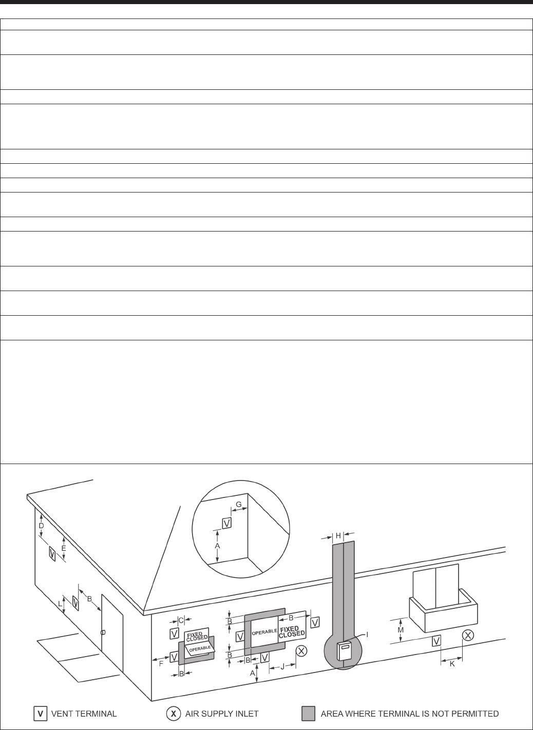
*When vent terminal is less than 10 feet (3m) horizontally
from a forced air inlet, the terminal must be at least 3 feet
(0.9m) above the air inlet.
Figure 12. Combustion Air and Vent Through Side Wall.
U.S. Installations (see note 1) Canadian Installations (see note 2)
A= Clearance above grade, veranda, porch, 12 inches (30 cm) 12 inches (30 cm)
deck, or balcony See note 6 See note 6
B= Clearance to window or door that may be Direct vent only: 12 inches (30cm); 36 inches (91 cm)
opened Other than Direct vent: 4 ft (1.2m) below or to
side of opening; 1 ft (30cm) above opening
C= Clearance to permanently closed window See note 4 See note 5
D= Vertical clearance to ventilated soft located
above the terminal within a horizontal See note 4 See note 5
distance of 2 feet (61cm) from the center
line of the terminal
E= Clearance to unventilated soft See note 4 See note 5
F= Clearance to outside corner See note 4 See note 5
G= Clearance to inside corner 3 feet (91 cm) minimum See note 5
H= Clearance to each side of center line 3 feet (91 cm) within a height 15 feet
extended above meter/regulator assembly See note 4 above the meter/regulator assembly
I= Clearance to service regulator vent outlet See note 4 3 feet (91 cm)
J= Clearance to nonmechanical air supply Direct vent only: 12" (30cm) 80-285; 36" (91cm)
inlet to building or the combustion air inlet 399-850. Other than Direct vent: 4 ft (1.2m) below 36 inches (91 cm)
to any other appliance or to side of opening; 1 ft (30cm) above opening
K= Clearance to a mechanical air supply inlet 3 feet (91 cm) above if within 10 feet (3 m) 6 feet (1.83 m)
horizontally
L= Clearance above paved sidewalk or paved Vent termination not allowed in this location Vent termination not allowed in this
driveway located on public property for category IV appliances. location for category IV appliances.
M= Clearance under veranda, porch, deck, See note 4 12 inches (30 cm) (see note 3)
or balcony
Notes:
1. In accordance with the current ANSI Z223.1 / NFPA 54 National Fuel Gas Code.
2. In accordance with the current CAN/CGA-B149 Installation Codes.
3. Permitted only if veranda, porch, deck, or balcony is fully open on a minimum of two sides beneath the oor.
4. For clearances not specied in ANSI Z223.1 / NFPA 54, clearance is in accordance with local installation codes and the requirements of the
gas supplier.
5. For clearances not specied in CAN/CGA-B149, clearance is in accordance with local installation codes and the requirements of the gas
supplier.
6. IMPORTANT: terminal must be placed such that it remains a minimum 12" above expected snow line. Local codes may have more
specic requirements, and must be consulted.

Page 15
Brute LX
3.3.3 Vertical Vent Terminal
When the unit is vented through the roof, the vent must
extend at least 3 feet (0.9m) above the point at which it
penetrates the roof. It must extend at least 2 feet (0.6m)
higher than any portion of a building within a horizontal
distance of 10 feet (3.0m), and high enough above the
roof line to prevent blockage from snow. When the
combustion air is taken from the roof, the combustion
air must terminate at least 12" (30cm) below the vent
terminal (see Figure 11).
3.3.4 Vertical Combustion Air Terminal
When combustion air is taken from the roof, a eld-
supplied rain cap or an elbow arrangement must be
used to prevent entry of rain water (see Figure 11). The
opening on the end of the terminal must be at least 12"
(30cm) above the point at which it penetrates the roof,
and high enough above the roof line to prevent blockage
from snow. When the vent terminates on the roof, the
combustion air must terminate at least 12" (30cm) below
the vent terminal.
3.3.5 Installations in the Commonwealth of
Massachusetts
In Massachusetts the following items are required if the
side-wall exhaust vent termination is less than seven
(7) feet above nished grade in the area of the venting,
including but not limited to decks and porches. From
Massachusetts Rules and regulations 248 CMR 5.08
1. Installation of Carbon Monoxide Detectors
At the time of installation of the side wall vented
gas fueled appliance, the installing plumber or gastter
shall observe that a hard-wired carbon monoxide
detector with an alarm battery back-up is installed on the
oor level where the gas appliance is to be installed. In
addition, the installing plumber or gastter shall observe
that a battery operated or hard-wired carbon monoxide
detector with an alarm is installed on each additional
level of the dwelling, building or structure served by
the side-wall horizontally vented gas fueled equipment.
It shall be the responsibility of the property owner to
secure the services of qualied licensed professionals for
installation of hard-wired carbon monoxide detectors.
a. In the event that the side-wall horizontally
vented gas fueled equipment is installed in a crawl
space or an attic, the hard-wired carbon monoxide with
alarm and battery back-up may be installed on the next
adjacent oor level.
b. In the event that the requirements of the
subdivision cannot be met at the time of completion of
installation, the owner shall have a period of thirty (30)
days to comply with the above requirements, provided,
however, that during said thirty (30) day period, a
battery operated carbon monoxide detector with an
alarm be installed.
2. Approved Carbon Monoxide Detectors
Each carbon monoxide detector shall comply
with NFPA 720 and be ANSI/UL 2034 listed and IAS
certied.
3. Signage. A metal or plastic identication plate
shall be permanently mounted to the exterior of the
building at a minimum height of eight (8) feet above
grade directly in line with the exhaust vent terminal
for horizontally vented gas fueled heating appliance
or equipment. The sign shall read, in print no less than
one-half (1/2) inch in size: "GAS VENT DIRECTLY
BELOW, KEEP CLEAR OF ALL OBSTRUCTIONS".
4. Inspection
The state or local gas inspector of the side-wall
horizontally vented gas fueled appliance shall not
approve the installation unless, upon inspection, the
inspector observes carbon monoxide detectors and
signage installed in accordance with the provisions of
248 CMR 5.08(2)(a) 1-4.

Page 16
BRADFORD WHITE CORP
.
NOTICE
At the time of removal of an existing boiler, the following
steps shall be followed with each appliance remaining
connected to the common venting system placed
in operation, while the other appliances remaining
connected to the common venting system are not in
operation.
1. Seal any unused openings in the common venting
system.
2. Visually inspect the venting system for proper size and
horizontal pitch and determine there is no blockage or
restriction, leakage, corrosion and other deciencies
which could cause an unsafe condition.
3. Insofar as is practical, close all building doors and
windows and all doors between the space in which
the appliances remaining connected to the common
venting system are located and other spaces of the
building. Turn on clothes dryers and any appliance not
connected to the common venting system. Turn on
any exhaust fans, such as range hoods and bathroom
exhausts, so they will operate at maximum speed.
4. Place in operation the appliance being inspected.
Follow the lighting instructions. Adjust thermostat so
the appliance will operate continuously.
5. Operate the main burner for 5 minutes then,
determine if the cut-draw overows to the discharge
opening. Use the ame of a match or a candle or the
smoke of a cigarette, a cigar or a pipe
6. Once it has been determined, according to the
method indicated above, that each device connected
to the drainage system is placed in the open air in
an adequate manner. Install the doors and windows,
fans, the registers of chimneys and gas appliances to
their original position
7. Tout mauvais fonctionnement du système d'évacuation
commun devrait être corrigé de façon que l'installation
soit conforme au National Fuel Gas Code, ANSI
Z223.1/NFPA 54 et (ou) aux codes d'installation CAN/
CSA-B149.1. Si la grosseur d'une section du système
d'évacuation doit être modiée, le système devrait
être modié pour respecter les valeurs minimales des
tableaux pertinents de l'appendice F du National Fuel
Gas Code, ANSI Z223.1/NFPA 54 et (ou) les codes
d'installation CAN/CSA-B149.1
AVIS
Au moment du retrait d'une chaudière existante, les
mesures suivantes doivent être prises pour chaque
appareil toujours raccordé au système d'évacuation
commun et qui fonctionne alors que d'autres appareils
toujours raccordés au système d'évacuation ne
fonctionnent pas:
1. Sceller toutes les ouvertures non utilisées du système
d'évacuation.
2. Inspecter de façon visuelle le système d'évacuation
pour déterminer la grosseur et l'inclinaison horizontale
qui conviennent et s'assurer que le système est
exempt d'obstruction, d'étranglement, de fuite,
de corrosion et autres défaillances qui pourraient
présenter des risques.
3. Dans la mesure du possible, fermer toutes les
portes et les fenêtres du bâtiment et toutes les
portes entre l'espace où les appareils toujours
raccordés au système d'évacuation sont installés et
les autres espaces du bâtiment. Mettre en marche
les sécheuses, tous les appareils non raccordés au
système d'évacuation commun et tous les ventilateurs
d'extraction comme les hottes de cuisinière et les
ventilateurs des salles de bain. S'assurer que ces
ventilateurs fonctionnent à la vitesse maximale. Ne
pas faire fonctionner les ventilateurs d'été. Fermer les
registres des cheminées.
4. Mettre l'appareil inspecté en marche. Suivre les
instructions d'allumage. Régler le thermostat de façon
que l'appareil fonctionne de façon continue.
5. Faire fonctionner le brûleur principal pendant 5 min
ensuite, déterminer si le coupe-tirage déborde à
l'ouverture de décharge. Utiliser la amme d'une
allumette ou d'une chandelle ou la fumée d'une
cigarette, d'un cigare ou d'une pipe.
6. Une fois qu'il a été déterminé, selon la méthode
indiquée ci-dessus, que chaque appareil raccordé
au système d'évacuation est mis à l'air libre de
façon adéquate. Remettre les portes et les fenêtres,
les ventilateurs, les registres de cheminées et les
appareils au gaz à leur position originale.
7. Tout mauvais fonctionnement du système d'évacuation
commun devrait être corrigé de façon que l'installation
soit conforme au National Fuel Gas Code, ANSI
Z223.1/NFPA 54 et (ou) aux codes d'installation CAN/
CSA-B149.1. Si la grosseur d'une section du système
d'évacuation doit être modiée, le système devrait
être modié pour respecter les valeurs minimales des
tableaux pertinents de l'appendice F du National Fuel
Gas Code, ANSI Z223.1/NFPA 54 et (ou) les codes
d'installation CAN/CSA-B149.1
3.4 Common Vent Test
NOTE: This section does not describe a method for
common venting Brute LX units. It describes what
must be done when an existing unit is removed from a
common vent system.
Brute LX units require special vent systems and fans for
common vent. See Section 3.2.1 or contact the factory
if you have questions about common venting Brute LX
units.
Page 17
Brute LX
WARNING:
Open ame can cause gas to ignite and result in
property damage, severe injury, or loss of life.
NOTE: The Brute LX appliance and all other gas
appliances sharing the gas supply line must be ring at
maximum capacity to properly measure the inlet supply
pressure. The pressure can be measured at the supply
pressure port on the gas valve. Low gas pressure could
be an indication of an undersized gas meter, undersized
gas supply lines and/or an obstructed gas supply line.
SCHED 40 METAL PIPE CAPACITY FOR 1.50 SPECIFIC GRAVITY
UNDILUTED PROPANE
NOMINAL PIPE SIZE @ 11" W.C. INLET AND 0.5" W.C. PRESSURE DROP
SIZE 1/2" 3/4" 1"
LENGTH MAXIMUM CAPACITY IN THOUSANDS OF BTU PER HOUR
20 200 418 787
40 137 287 541
60 110 231 434
80 94 197 372
100 84 175 330
NOTES: 1. Follow all local and national LP gas codes for line sizing and
equipment requirements. 2. Verify that inlet gas pressure remains between
4 and 13 inches of water column before and during operation.
Source: ANSI Z223.1-80 National Fuel Gas Code.
Table 9. Nominal Pipe Size, Propane
SCH 40 METAL PIPE CAPACITY FOR 0.60 SPECIFIC GRAVITY NATURAL GAS
NOMINAL PIPE SIZE @ 0.30" W.C. PRESSURE DROP
LENGTH 1/2" 3/4" 1"
FT CUBIC FEET OF GAS PER HOUR
20 92 190 350
40 130 245
60 105 195
80 90 170
100
Table 10. Nominal Pipe Size, Natural Gas
SECTION 4.
Gas Supply and Piping
4.1 Gas Supply and Piping
Gas piping should be supported by suitable hangers or
oor stands, not the appliance.
Review the following instructions before proceeding
with the installation.
1. Verify that the appliance is tted for the proper type
of gas by checking the rating plate. Brute LX will
function properly without the use of high altitude
modication at elevations up to 10,000 feet (3050
m).
2. The maximum inlet gas pressure must not exceed
13" W.C. (3.2kPa). The minimum inlet gas pressure
is 4" W.C. (1.0kPa).
3. Refer to Table 11, Table 10, Table 9 and Table 12 to
size piping.
4. Run gas supply line in accordance with all
applicable codes.
5. Locate and install manual shutoff valves in
accordance with state and local requirements.
6. A sediment trap must be provided upstream of the
gas controls.
7. All threaded joints should be coated with piping
compound resistant to action of liqueed petroleum
gas.
8. The appliance and its individual shutoff valve must
be disconnected from the gas supply piping during
any pressure testing of that system at test pressures
in excess of 1/2 PSIG (3.45kPa).
9. The unit must be isolated from the gas supply
system by closing its individual manual shutoff
valve during any pressure testing of the gas supply
piping system at test pressures equal to or less than
1/2 PSIG (3.45kPa).
10. The appliance and its gas connection must be leak
tested before placing it in operation.
11. Purge all air from gas lines.
Page 18
BRADFORD WHITE CORP
.
Brute LX NATURAL GAS REQUIRED
SIZE CU FT / HR INPUT RATE.
50 50
75 75
100 100
125 125
150 150
175 175
220 220
TO SIZE PIPING:
Measure linear distance from meter outlet to last boiler. Add total input of all
boilers and divide by 1000 to obtain cu ft / hr required. Add total equivalent
length of ttings used according to Table 6B. Align total length (pipe and
ttings) on left side column of Table 6C with highest cubic feet of gas required.
NOTES: Consult and conrm with Applicable Fuel Gas Code before
beginning work. Verify gas inlet pressure is between 4 and 13 in W.C.
before starting boiler.
Table 11. Natural Gas Required
EQUIVALENT LENGTHS OF STRAIGHT PIPE FOR TYPICAL SCH 40 FITTINGS
NOMINAL PIPE SIZE
FITTING 1/2" 3/4" 1"
LINEAR FEET
90° ELBOW 3.6 4.4 5.2
TEE 4.2 5.3 6.6
Table 12. Equivalent Pipe Lengths.
Table 13. DHW, Performance Data.
SECTION 5.
Pump Capacity
5.1 Brute LX Heating System Pump
Capacity
Brute LX's internal pump is sized for a maximum of
30 ft total equivalent pipe. Bradford White strongly
recommends the unit to be piped in primary/secondary
fashion, or use a low loss header/hydraulic separator.
Please contact Bradford White for further application
details.
Table 11
DHW Performance Data
At various cold water inlet temperatures
Model: 125
50 60 70
GPM
2100 97 95
379 77 75
459 58 56
548 46 45
Model: 150
50 60 70
GPM
395 92 90
471 69 68
648 46 45
836 35 34
Model: 175
50 60 70
GPM
483 81 79
567 65 63
655 54 53
842 40 39
Temp Rise F
Inlet Temp F
Temp Rise F
Inlet Temp F
Temp Rise F
Inlet Temp F
125
150
175
SECTION 6.
Water Connections
6.1 Central Heat System Piping
NOTE: This appliance must be installed in a closed
pressure system with a minimum of 12 psi (82.7kPa)
static pressure at the boiler.
Hot water piping should be supported by suitable
hangers or oor stands. Do not support piping with this
appliance. Due to expansion and contraction of copper
pipe, consideration should be given to the type of hangers
used. Rigid hangers may transmit noise through the
system resulting from the piping sliding in the hangers.
It is recommended that padding be used when rigid
hangers are installed. Maintain 1" (2.5cm) clearance to
combustibles for hot water pipes.
Pipe the discharge of the pressure relief valve (full size)
to a drain or in a manner to prevent injury in the event of
pressure relief. Minimum ll pressure must be 12psig
(82.7kPa). Install shutoff valves where required by code.
CAUTION
PRV (included) must be installed immediately at boiler
outlet with no valves between. Use PRV adapter pipe
(included) for bottom connections or add PRV directly
to the top of boiler with pipe coupling.
__________________________________________
ATTENTION
PRV (inclus) doit être installé immédiatement à sortie
chaudière avec pas de vannes entre. Utiliser le PRV
tuyau adaptateur (inclus) pour les connexions bas ou
ajouter PRV directement vers le haut de la chaudière
avec raccord de tuyau.
__________________________________________
Suggested piping diagrams are shown on the following
pages. These diagrams are meant only as a guide.
Components required by local codes must be properly
installed.
Page 19
Brute LX
NOTE: Bradford White supplied pumps are not all
capable of maintaining the reduced temperature rise
required with glycol concentrations greater than
35%.
NOTICE
Different glycol products may provide varying
degrees of protection. Glycol products must be
maintained properly in a heating system, or they may
become ineffective. Consult the glycol specications,
or the glycol manufacturer, for information about
specic products, maintenance of solutions, and set
up according to your particular conditions.
6.4 Recognized Chemicals
The following manufacturers offer glycols, inhibitors,
and anti-foamants that are suitable for use in the Brute
LX. Please refer to the manufacturers instructions for
proper selection and application.
1. Sentinel Performance Solutions Group
2. Hercules Chemical Company
3. Dow Chemical Company
6.5 Domestic Hot Water Piping (BLXC)
Connect domestic hot and cold water piping to the
boiler at locations noted in Figure 14. Expected DHW
performance is indicated in Table 13.
Use of ow restrictor is optional to prevent colder water
at excessive ow rates. Contact Bradford White for
alternate congurations.
6.6 Indirect Water Heater Piping
The BLXH model can control an indirect water heater
zone. Pipe to the locations shown in Figure 14. Setpoint
is made via aquastat or sensor well located on the
indirect water heater, or can be controlled at the boiler
via a remote sensor. See Section 9 for control details.
Sensor, Bradford White PN E2337501
Brute LX's efciency is higher with lower return
water temperatures.
Bradford White strongly recommends that Brute LX
be piped in a primary-secondary fashion (using either
piping or a hydraulic separator) such that the pump that
is mounted on the boiler ONLY serves the boiler.
Brute LX boiler must be located within 15 feet (4.6m)
of the supply and return header (or the hydraulic
separator). The pump is sized for a maximum of 30 feet
(9.1m) of piping and the headloss of the boiler only.
The system designer should take into account allowable
boiler temperature rise of 65°F (36°C) Maximum.
6.2 Cold Water Make-Up
1. Connect the cold water supply to the inlet
connection of an automatic ll valve.
2. Install a suitable back ow preventer between
the automatic ll valve and the cold water supply.
3. Install shut off valves where required.
The boiler piping system of a hot water heating boiler
connected to heating coils located in air handling
appliances where they may be exposed to refrigerated
air circulation, must be equipped with ow control
valves or other automatic means to prevent gravity
circulation of the boiler water during the cooling cycle.
A boiler installed above radiation level, or as required
by the authority having jurisdiction, must be provided
with a low water cutoff device at the time of boiler
installation.
6.3 Freeze Protection
Brute LX units are certied for indoor use only, and are
not design-certied for placement outdoors.
Proper precautions for freeze protection are
recommended for boiler installations in areas where the
danger of freezing exists.
Power outage, interruption of gas supply, failure of
system components, activation of safety devices, etc.,
may prevent a boiler from ring. Any time a boiler is
subjected to freezing conditions, and the boiler is not
able to re, and/or the water is not able to circulate,
there is a risk of freezing in the boiler or in the pipes
in the system. When water freezes, it expands which
may result in bursting of pipes, or damage to the boiler,
which could result in leaking or ooding conditions.
Do not use automotive antifreeze or ethylene
glycol. To help prevent freezing, Bradford White
recommends the use of inhibited propylene glycol
concentrations between 20% and 35% glycol. Typically,
this concentration will serve as burst protection for
temperatures down to approximately -5°F (-20°C).
If temperatures are expected to be lower than -5°F
(-20°C), glycol concentrations up to 50% can be used.
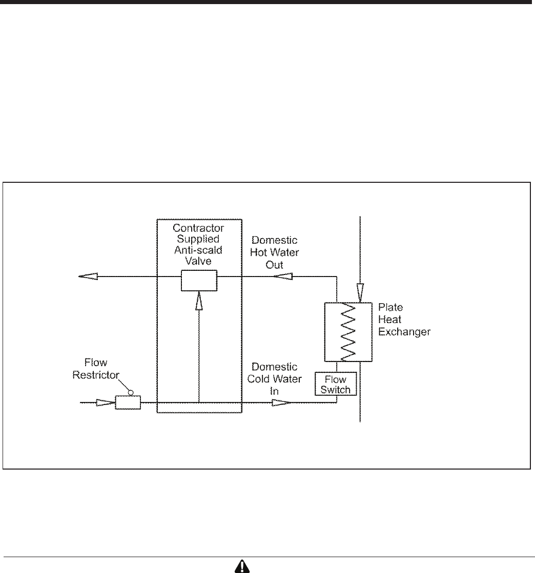
Page 20
BRADFORD WHITE CORP
.
CAUTION
Condensate is mildly acidic (pH=5), and may harm some oor drains and/or pipes, particularly those that are
metal. Ensure that the drain, drainpipe, and anything that will come in contact with the condensate can withstand
the acidity, or neutralize the condensate before disposal. Damage caused by failure to install a neutralizer kit
or to adequately treat condensate will not be the manufacturer’s responsibility.
Contact Bradford White to order Kit# A2123601
__________________________________________________________________________________________
Figure 13. DHW Connections with Anti-Scald Valve
and Flow Restrictor.
6.7 Condensate Drain
A condensate drain trap is built into the Brute LX.
Connect a 3/4” PVC pipe between the drain connection
and a condensate neutralizer before entering drainage
system.
The condensate drain and included trap must be
installed. When a condensate pump is not used, the
tubing must continuously slope downward toward the
drain with no spiraling.
Consult local codes for the disposal method.
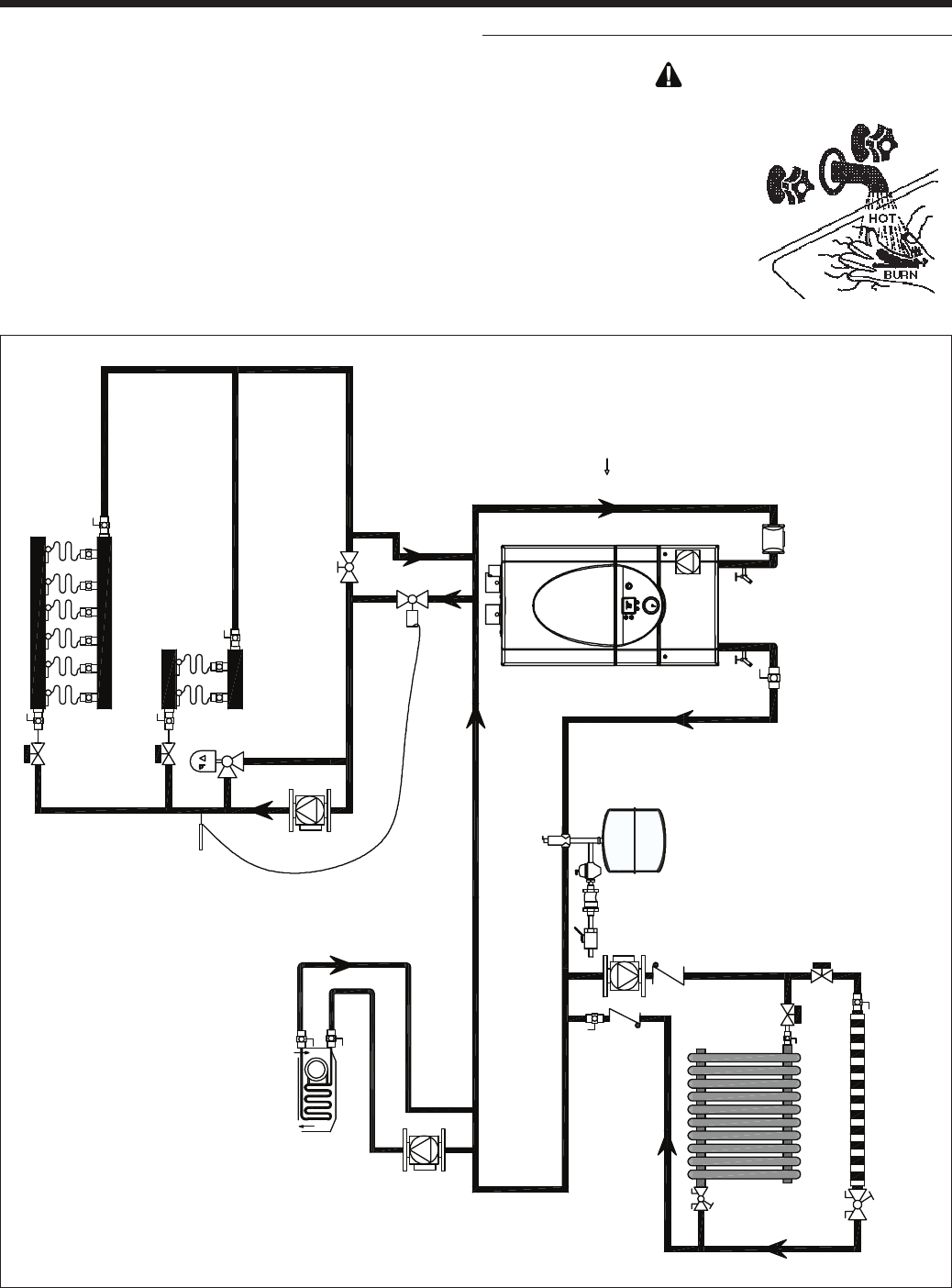
Page 21
Brute LX
Figure 14. Hydronic Piping — High and low temp zones.
6.8 Piping Schematics
Figure 14 through Figure 19 illustrate typical piping
congurations for Brute LX boilers. These diagrams
are only meant as a guide. All components or piping
required by local code must be installed.
CAUTION
Scalding Risk: Bradford White recommends
the use of a thermostatic mixing
valve at domestic hot water
outlet (boiler location) to
reduce potential for scalding.
Contact Bradford White for
recommended models.
_____________________________________________
Heating
Supply
Air Eliminator
Sediment
trap
Expansion tank and auto feed
Heating
Return
* *
* *
* *
*Closely spaced tee's - 4 pipe diameters apart
Mascot LX - residential high and low temp. zones
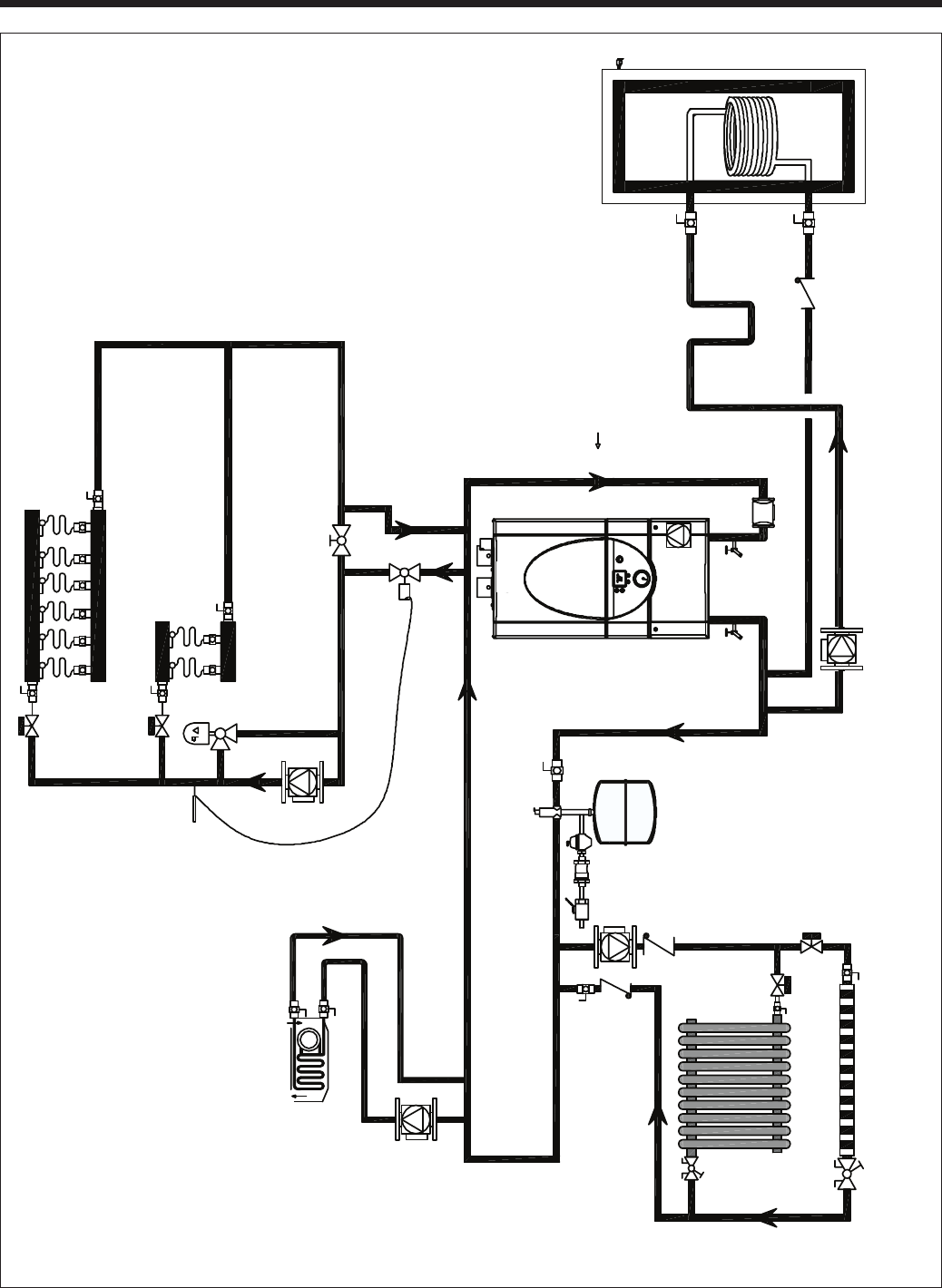
Page 22
BRADFORD WHITE CORP
.
Figure 15. Hydronic Piping (only) — with an indirect tank as a zone.
Mascot LX - residential high and low temp.
zones w/ indirect water heater
Heating
Supply
Air Eliminator
Sediment
trap
1" piping to DHW
Indirect DWH Tank
18"
heat
trap
Expansion tank and auto feed
Heating
Return
* *
* *
* *
* *
*Closely spaced tee's - 4 pipe diameters apart
Mascot LX - residential high and low temp.
zones w/ indirect water heater
Heating
Supply
Air Eliminator
Sediment
trap
1" piping to DHW
Indirect DWH Tank
18"
heat
trap
Expansion tank and auto feed
Heating
Return
* *
* *
* *
* *
*Closely spaced tee's - 4 pipe diameters apart
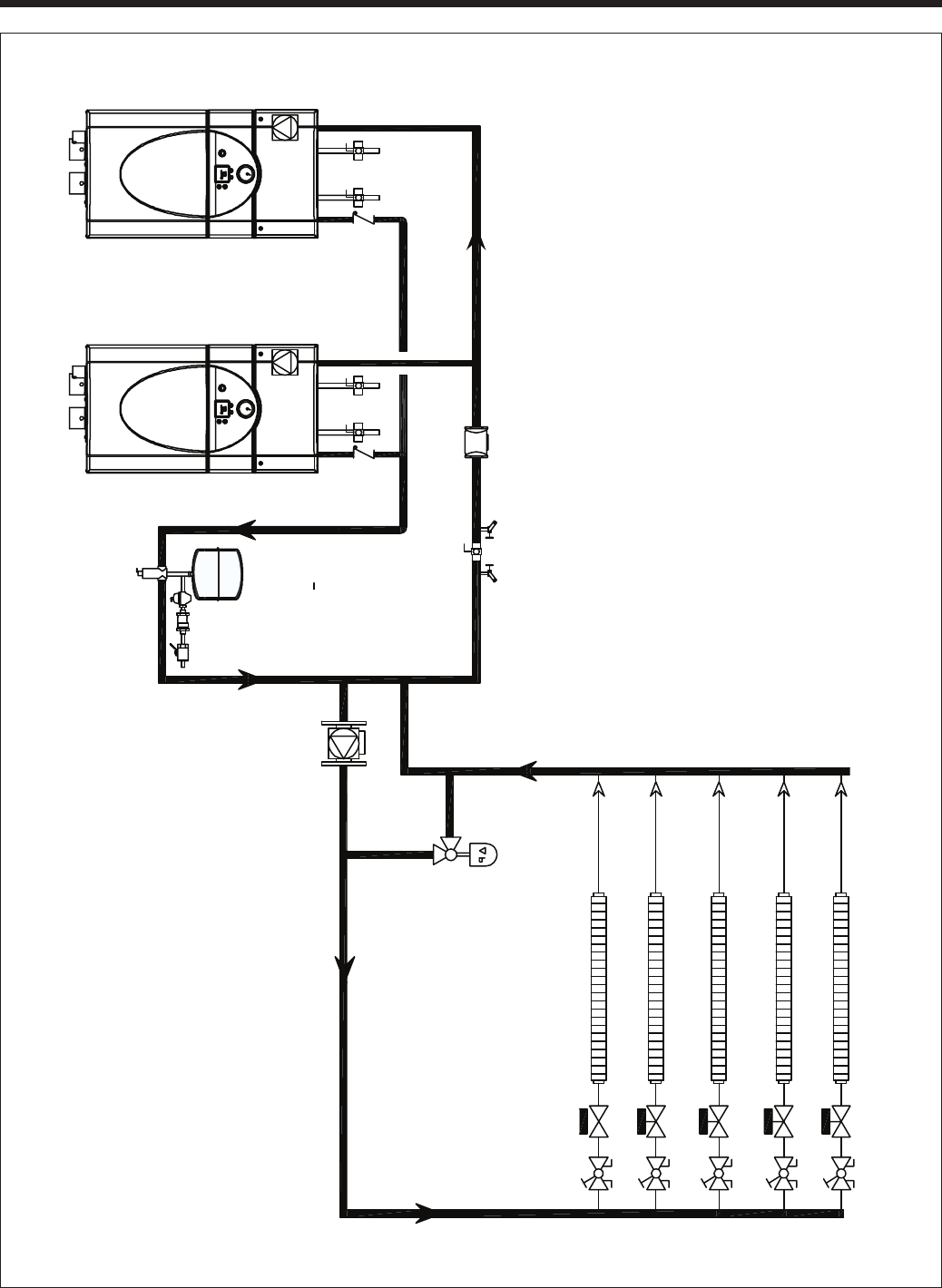
Page 23
Brute LX
Figure 16. Hydronic Piping — BLXC Multi boilers for large homes with long / multiple baseboard zones.
Zones with:
-zone valves 24V
-balancing valves
Air seperator
DHW
1-1
4"
Primary
loop
Multi Mascot LXs for Large house
residential with long / muliple baseboard
zones
*Closely spaced tee's - 4 pipe diameters apart
Purge/drain valves
DHW
Sediment trap
check valve check valve
Expansion
tank and auto
feed
* *
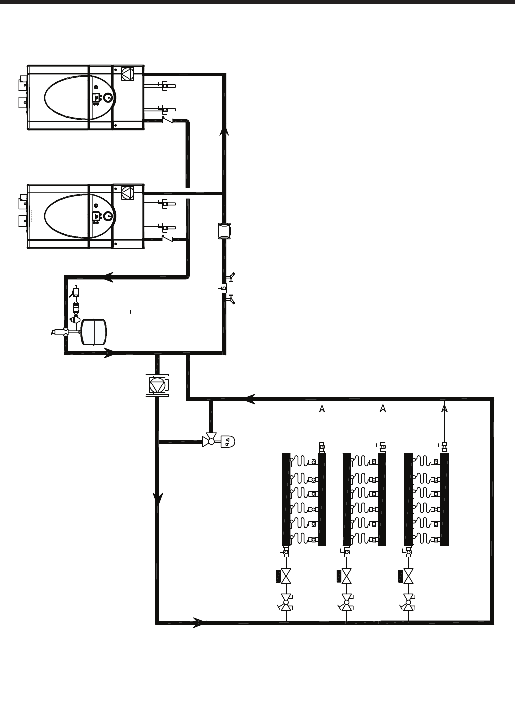
Page 24
BRADFORD WHITE CORP
.
Figure 17. Hydronic Piping — BLXC Multi boilers for large homes with long / multiple radiant zones.
Zones with:
-zone valves 24V
-balancing valves
1-1
4"
Primary
loop
Multi Mascot LX boilers for Large house
residential with long / muliple radiant zones
*Closely spaced tee's - 4 pipe diameters apart
Purge/drain valves
Note: Expansion tank may be required
if system volume is over 50 gallons
Sediment trap
Expansion tank and auto feed
* *
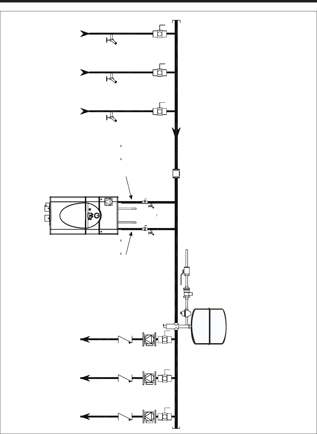
Page 25
Brute LX
Figure 18. Hydronic Piping — BLXC Heating zones piped with zone pumps.
Mascot LX Combi -Hydronic piping
-Heating zones piped with Zone pumps
Water Feed controls
Expansion tank
air vent Purge/drain valves
DHW
1 1
4"
Primary
loop
Increase from 3
4 to 1 1
4
Sediment trap
*Closely spaced tee's - 4 pipe diameters apart
Increase from 3
4 to 1 1
4
Manifold size based on
number of zones required
Manifold size based on
number of zones required
* *
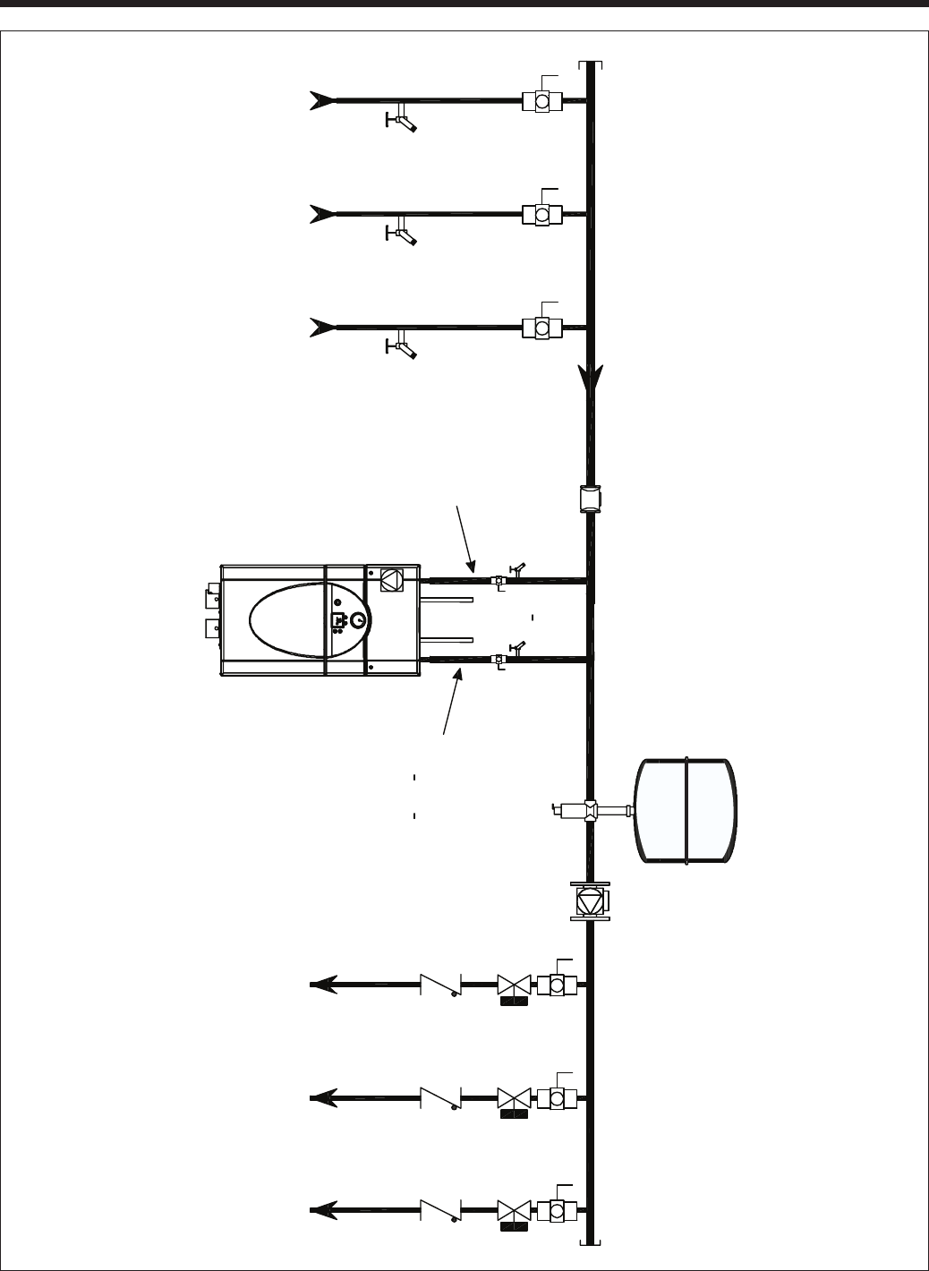
Page 26
BRADFORD WHITE CORP
.
Figure 19. Hydronic Piping — Heating zones piped with zone valves.
Expansion tank
air vent
Purge/drain valves
DHW
1 1
4"
Primary
loop
Sediment trap
*Closely spaced tee's - 4 pipe diameters apart
Increase from 3
4 to 1 1
4
Manifold size based on
number of zones required
Manifold size based on
number of zones required
Mascot LX Combi -Hydronic piping
-Heating zones piped with Zone valves
* *
Page 27
Brute LX
SECTION 7.
Electrical Connections
WARNING
The appliance must be electrically grounded in
accordance with the requirements of the authority having
jurisdiction or, in the absence of such requirements, with
the latest edition of the National Electrical Code, ANSI/
NFPA 70, in the U.S. and with latest edition of CSA
C22.1 Canadian Electrical Code, Part 1, in Canada. Do
not rely on the gas or water piping to ground the metal
parts of the boiler. Plastic pipe or dielectric unions may
isolate the boiler electrically. Service and maintenance
personnel, who work on or around the boiler, may be
standing on wet oors and could be electrocuted by an
ungrounded boiler. Electrocution can result in severe
injury or death.
Single pole switches, including those of safety controls
and protective devices must not be wired in a grounded
line.
All electrical connections are made on the terminal
blocks that are located inside the control panel.
NOTE: All internal electrical components have been
prewired. No attempt should be made to connect
electrical wires to any other location except the terminal
blocks.
CAUTION
Label all wires prior to disconnection when servicing
controls. Wiring errors can cause improper and
dangerous operation. Verify proper operation after
servicing
CAUTION
Brute LX supply voltage must not be disengaged,
except for service or isolation, or unless otherwise
instructed by procedures outlined in this manual. To
signal a call for heat, use the 24V DC eld-interlock,
as shown in the wiring diagram(s).
7.1 Main Power
Plug power cord into a non-switched 115V electrical
outlet with 15A circuit protection. FLA is 2A. There
is an internal 10A breaker to protect internal system
components.
7.2 Pump Connections
Brute LXC energizes boiler pump (opens 3-way valve),
and system pump upon a demand for Central Heat.
Brute LXH energizes boiler pump and system pump
upon a central heat demand
The combined load for all pumps must not exceed
5 amps. In some installations, a pump relay may be
required.
7.3 24Vac Transformer with Circuit Breaker
24Vac is supplied by a transformer mounted behind the
lower door. All 24Vac power is supplied
through a 2A
circuit breaker located behind lower door.
7.4 Central Heat - Call for Heat
Connect the Call for Heat to terminals #5 and #6
(connections labeled "T-T or interlock").
7.5 Outdoor Air Temperature Sensor
Connect the outdoor air temperature sensor to
connections labeled "Outdoor sensor." The outdoor air
temperature sensor is used for warm weather shutdown
and outdoor reset. If an outdoor sensor is not installed,
the CH setpoint of the boiler is limited to 140°F.
7.6 Domestic Hot Water Connection
For indirect water heater, connect aquastat for remote
sensor to terminals #7 & #8 or domestic hot water
sensor to terminals #9 & #10 (see Figure 21).
Domestic Hot Water Sensor PN is E2337501
7.7 System Sensor
Connect the system sensor to connections labeled
"system sensor" on lead boiler only. #3 and #4
7.8 External Control Connections
If the unit is being controlled by an external 0-10VDC
signal, connect this to terminals 11 and 12. When
making the connections, follow the polarity designations
shown on the label. A "dry" alarm contact is located on
terminals 10 and 11 at high voltage panel (backside).
Note: The 0-10VDC signal may be to send a modulation
signal, or a temperature setpoint signal to the boilers
from a building management program (See Section 9).
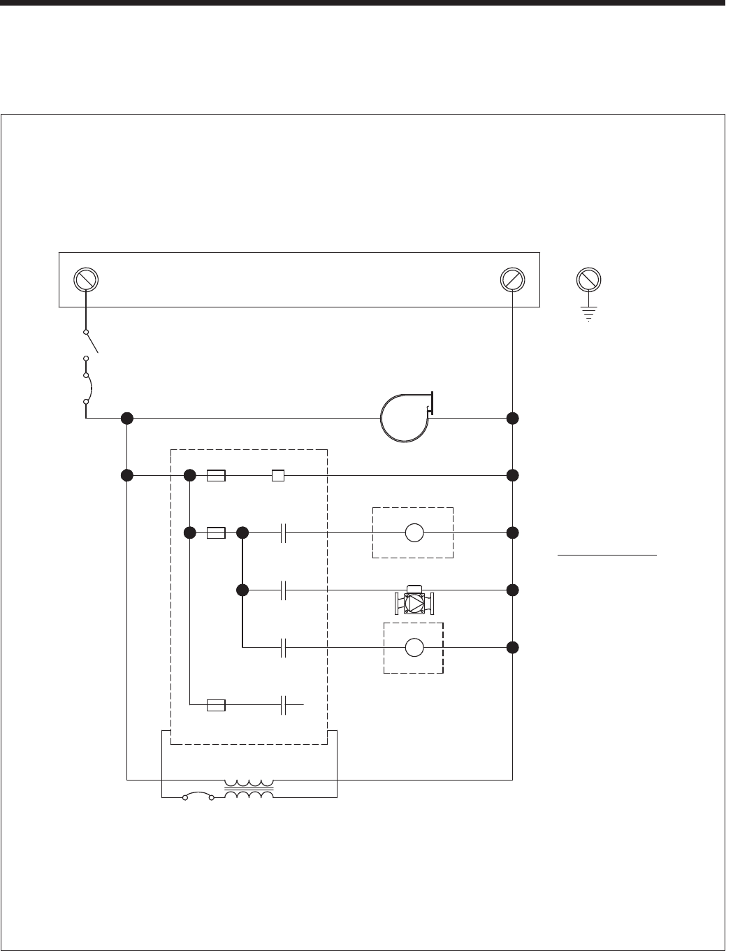
Page 28
BRADFORD WHITE CORP
.
Figure 20. Ladder Diagram.
SYSTEM
SENSOR
FLAME
ROD
HI LIMIT
SWITCH
BLDG MGMT
SYSTEM IN
FIELD
INTERLOCKS
AIR
PRESSURE
SWITCH
OUTDOOR
SENSOR
H-X/DHW
SENSOR
TANK
AQUASTAT
COND.
LEVEL
SWITCH
BLOCKED
VENT SW
HI-LO GAS
PRESS SW
WATER
PRESS
SWITCH
X11-7
X2-3
X11-14
X2-6
24
VAC
FLOW
SWITCH
CIRCUIT
BREAKER
ON/0FF
SWITCH
IMPORTANT NOTE
Maximum COMBINED load
on Terminals PWB 4, 6
and 8 shall NOT exceed
5 Amps
PWB
120VAC
NEUTRAL
BLOWER
MAIN CONTROL
120 VAC
24 VAC
PWB-3 PWB-2
PWB-1
X3-4
F3
X11-10
SUPPLY
24VDC
800mA
F1
5A
5A
F2
X3-12
BOILER PUMP
R
R
SYSTEM PUMP
X3-7
X3-6
RELAY
DHW PUMP
RELAY
PWB-4
PWB-6
PWB-8
INLET PROBE
FLUE TEMP
FLUE SAFETY
OPERATING CONTROL
SAFETY LIMIT
H-X/DHW SENSOR
X4-3
X4-9
X4-2
X4-8
X4-1
X3-15,PWB-9
X3-14,PWB-7
X3-5 X3-13,PWB-5
X4-7
FLOW SENSOR
X4-10
X4-4
X4-5
X4-11
X4-12
X11-11
X11-13
X11-5
X11-12
X11-4
X11-6
X11-9
X11-8
X11-1
X11-2
BLOWER
X6-4 FWB1
X6-12
X6-5
X6-13
X6-6
X6-14
X6-7
X6-15
FWB2
FWB3
FWB4
FWB5
FWB6
FWB7
FWB8
FWB9
FWB10
FWB11
X4-4
X4-10
X5-6
X5-3
X5-1
X5-8
X5-5
X1-2
X1-1
X1-3
FWB12
FWB13
FWB14
FWB15
FWB16
FWB17
FWB18
FWB19
0-10 VDC IN
+
-
+
-
0-10 VDC OUT
RATE OUT
GROUND
SHIELD
SHIELD
RS485A
RS485B
CASCADE
SPARE
BY OTHERS
X6-2
X6-10
C
GAS VALVE
X2-1
X2-4
X6-1
X6-9
X11-3
LWCO
X11-7
X11-14
X1-4
X3-10
TR2
T2
CAUTION - HIGH VOLTAGE SPARK WIRE
X4-5
X4-11
X4-12
FLOW SENSOR
MAIN CONTROL
FWB
X3-8
USED ON LABEL H2365000
SHEET 1 OF 2
B
CD 5-22-14
C
INTENDED SIZE:
D
C
B
A
B
C
D
1
2
3
4
REV.
JAB 12/4/13
CJ 12/4/13
ENGR
APPR
43
DRAFT
2
APPROVALS
1
JM 5-22-14
C
GRAPHIC CORRECTION
CHECK
DRAFT
ECN ENGR APPR APPR
BY LAARS HEATING SYSTEMS CO. CHANGE:
14-016N-08
REV.
DISCLOSED TO OTHERS FOR MANUFACTURING OR ANY OTHER
.010
REVISIONS
PURPOSE EXCEPT AS SPECIFICALLY AUTHORIZED IN WRITING
N/A
FRACTIONS 1/8"
1
DWG. NO:
FINISH E23587
TITLE:
SOFTWARE
TOLERANCES ARE:
REPRODUCED, TRANSFERRED TO OTHER DOCUMENTS, USED OR
DECIMALS .XXX
.1
S
N/A
DECIMALS .XX
MATERIAL: LADDER DIAGRAM, MASCOT LX
.03
DECIMALS .X DIMENSIONS ARE IN INCHES.
UNLESS OTHERWISE SPECIFIED:
THIS DOCUMENT AND THE INFORMATION CONTAINED HEREIN ARE
PROPRIETARY TO LAARS HEATING SYSTEMS CO.AND SHALL NOT BE
ANGLES
DO NOT SCALE DRAWING.
THIRD ANGLE PROJECTION.
SCALE: NONE
7.9 Ladder Diagram, Connections, and Wiring Diagrams
(see Figure 20 thru Figure 22)
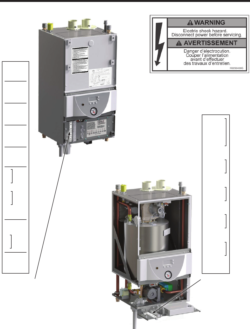
Page 29
Brute LX
Figure 21. Field Wiring Connections
High Voltage
Field Connections
(located behind the
inside lower panel)
Shown at
actual size
Shown at
actual size
Low Voltage
Field Connections
(located on the front of
the inside lower panel)
OUTDOOR
SENSOR
SYSTEM
SENSOR
TANK
AQUASTAT
DHW
SENSOR
DC OUT
DC IN
GROUND
GND
MOD
BUS
SAFETY
INTERLOCK
T-T
1-
2-
3-
4-
5-
6-
7-
8-
9-
10-
11 +
12 -
13 +
14 -
15-
16-
17-A
18-B
19-
20-
H2366000C
DHW
PMP
1- GROUND
2- NEUTRAL
3- LINE
4- SYS PMP
5- NEUTRAL
6-
7- NEUTRAL
8- BOILER PMP
9- NEUTRAL
10-
11-
12- SPARE
H2366001C
ALARM
CONTACT
3.00
1.75
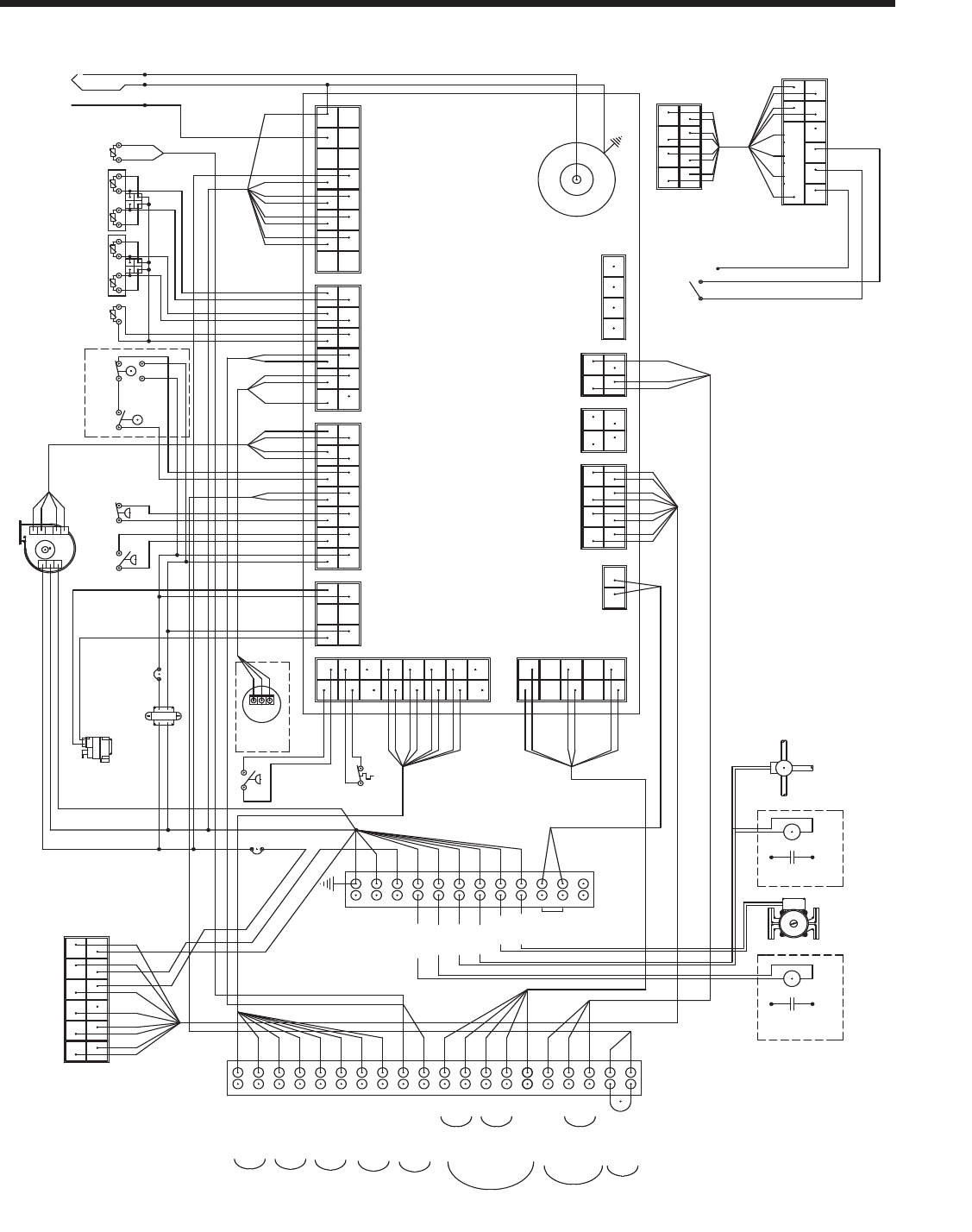
Page 30
BRADFORD WHITE CORP
.
Figure 22. Wiring Diagram.
BOILER
PUMP
SYSTEM PUMP
RELAY
CIRC U IT
BR EA KER
CIRC U IT
BR EA KER
FLOW
SWITCH
AIR
PR ESSU RE
SWITCH
BLOC KED
VEN T SW
LO W
WA TER
CUT OFF
SPARK
IG N ITO R
H-X/DHW
SENSOR
OPER .
CONTR O L
SAFETY
LIMIT
FLOW
SENSO R
FLAME
SENSO R
HI LIM IT
SW I TC H
WATER
PR ESSU RE
SWITCH
DHW PUMP
RELAY
INLET
PR O BE
FLUE
TE M P
FLUE
SA FETY
12
1
6
12 7
DISPLAY
HARNESS
(E23579)
1
YO
4
1 2
43
1 2
3
RR
PWB
T2
FWB
G
GND
3 WAY VALVE
CO MBI UNITS ONLY
SPARE
Y
R
G
W
COMBI O NLY
BLGY
O
O
O
O
O
V
OPTIONAL
O
V
SAFETY
MODBUS
A
V
FROM X1
O
O
G
W
G
INTERLOCK
FRO M X 4
FRO M X6
MAIN CONTROL
TR ANS F O RM E R
GAS V A LV E
W
BK
W
BK
DHW
Y
R
Y
BL
R
DC O UT
DC IN
SENSOR
SENSOR
AQ UASTAT
TANK
NEUT
NEUT
NEUT
LINE
LINE
LINE
INTERLK T
FIELD T
GRO UND
21
21
4
2
BL
1
4
8
5
SENSOR
OUTDOOR
L1 IN
NEUTRAL
GROUND
SYSTEM
R
W/V
V
V
BK
G
FROM X5
BR
TO /FRO M X3
GY
BL
GY
O
R
BK
Y
BL
W
1
GY
W/R
R
BK
1
W
W/GY
G
BLO W ER
94
22
8411
9
712
6
4
2
11
16
18
61
71
5
1
3
16
BL
BR
R
G
8
10 5
GY
V
1
G
BK
G
Y
GY
R
W
BL
Y
BK
R
O
Y
BR/G
V
O
R
BR
BK
GY
W
BL
Y
W
V
W/V
BK
W/R
G
R
GY
W/GY
R
V
G
W
O
O
R
Y/R
R
BL
Y
Y
X5 X1
X6
3X4X11X2X
X7
X8 X9
20 40
21
12 24
13
GY
Y
O
BR
R
G
V
BL
Y
BR
R
BL
GY
O
BK
W
G
V
BK/R
FROM XO
FROM X8
FROM FWB
FROM FWB
FROM PWB
PUMPS BY OTHERS
WHEN REQ'D
O
GY
BL
Y
GY
O
BR
R
BR
V
Y
G
W
BK
BK/R
R
G
V
BL
W
BK
BK/R
BK
G
G
BK
W
W
BK
G
G
BR /G
Y
1
FACE DOW N
3
XO
FEMALE
(TO XX)
POW ER
SW ITC H
X8
FROM H-X/D HW SEN SO R
FROM FWB
O
O
O
O
BK
V
O
O
3
XX
MALE
(TO XO)
2
1
O
O
FROM X11
FACE UP
O
W
G
2
1
X12
Y
BR
ALARM
CONTACTS
Y
BR
+
-
-
+
B
2 4
5
8
61
7
H2365100D
WIRE DIAGRAM
BRUTE LX
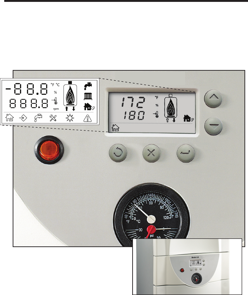
Page 31
Brute LX
SECTION 8.
Control Setup and Operation
The Brute LX control is an integrated electronic control
that includes ame control, safety device monitoring
and pump regulating functions. The control regulates
the heat input by controlling the blower speed and
activating the gas valve. The board controls the ignition
sequencing and monitors signals received by all boiler
sensors. The control regulates the boiler set temperatures
and operating modes. For typical heating and DHW
operation, the control is programmed to give priority to
domestic hot water. The control is setup using the User
Interface which contains 5 buttons and a digital display.
Figure 23. The User Interface
The User Interface is located on the one panel of
the Brute LX that is not removable. It contains all the
buttons and gauges that are necessary to contol and
monitor the unit. See Figure 23
8.1 Digital Display
The centerpiece of the User Interface is the Digital
Display. All of the needed parameters of the Brute LX
can be viewed and monitored on this Digital Display.
All controls can be adjusted using the SELECT / OK
button and the Up and Down arrows.
Descriptions of the icons used in the display are
shown in Figure 24.
On/Off
Power
Temperature and
Pressure Gauges
Reset Cancel SELECT / OK
Up
(next)
Down
(next)
Looping
Scroll
BRUTE LX
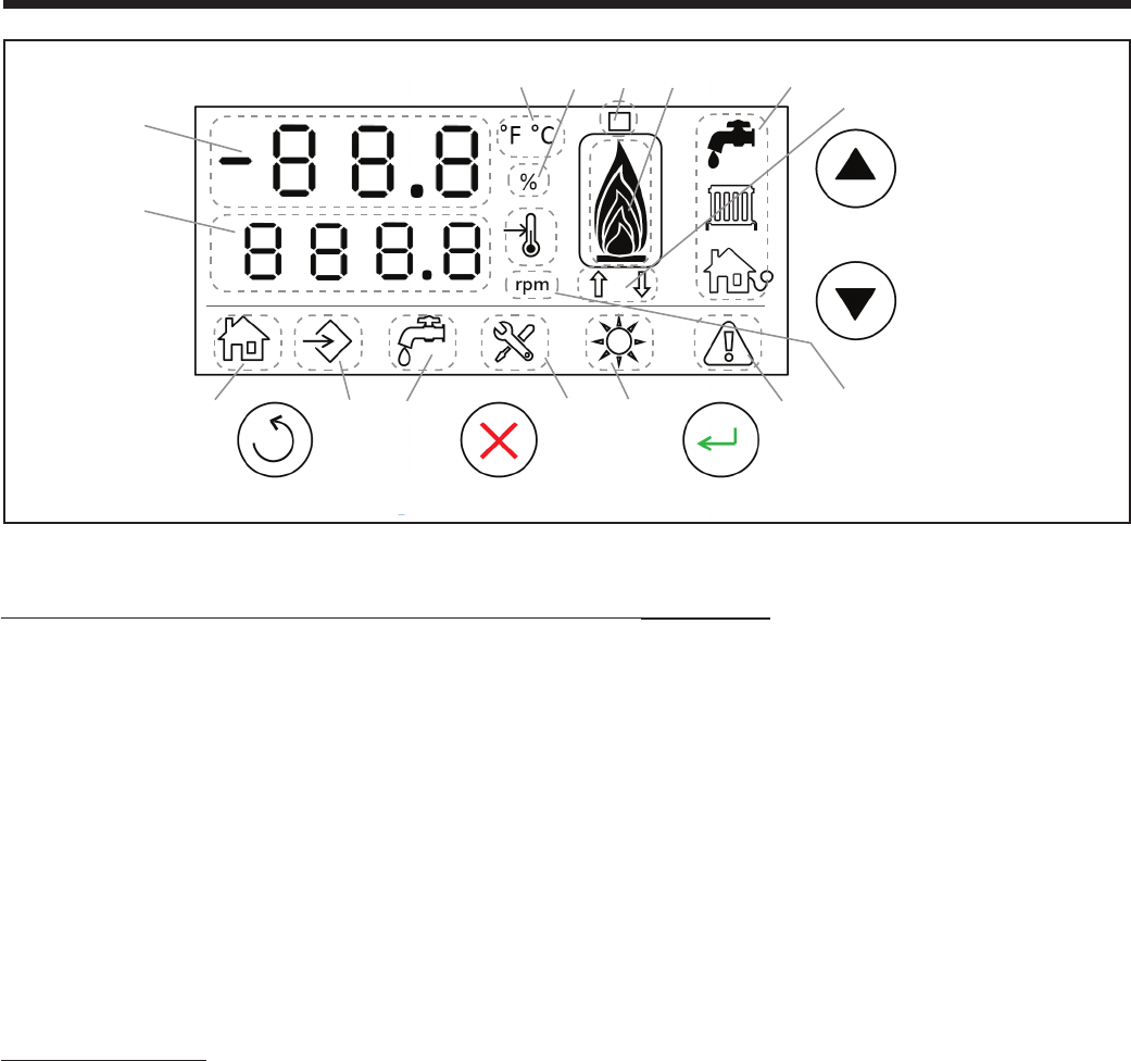
Page 32
BRADFORD WHITE CORP
.
8.2 CONTROLLER Modes
Three control modes can be displayed: USER,
INSTALLER, and SERVICE.
USER Mode is for a homeowner or service technician
to adjust the most common operating parameters
(See Table 14).
INSTALLER Mode allows an installer access to
all of the parameters for installation, setup, and
reconguration of the boiler.
SERVICE mode is used only by trained Brute LX
technicians.
Figure 24. Display Icons
These icons and numbers are always displayed (either outlined or 'Darkened')
1- Current or set temperature, parameter number, modulation percentage.
2- Set temperature, parameter value, error code, announcement code.
3- Temperature unit (will show either Fahrenheit or Celsius).
4- Percentage or temperature set point.
5- Icon 1 displays the ue temperature when 'Darkened'.
6- Icon 1 displays inlet temperature when arrow up is 'Darkened',
outlet temperature when arrow down is 'Darkened',
differential (outlet –inlet) temperature when both arrows are 'Darkened'.
7- DHW/Tank temperature, System temperature, Outdoor temperature.
When respective probe is present, the icon outline will be outlined. When the respective temperature
will be displayed, the icon inner part will be 'Darkened'.
8- Heat input in ve steps (20%, 40%, 60%, 80%, 100%).
Will be visible when,
9- Heat demand is active.
10- External demand is active (e.g. cascade master or 0-10V input).
11- DHW demand is active.
12- Service is required or when in installer mode.
13- Summer mode is present (only DHW request will be satised).
14- Boiler is in lockout.
15- Revolutions Per Minute (fan speed, shows only in Service Mode).
Reset Cancel SELECT / OK
Looping
Scroll
Up
(next)
Down
(next)
1
2
3458 7
6
910 11 12 13 14 15
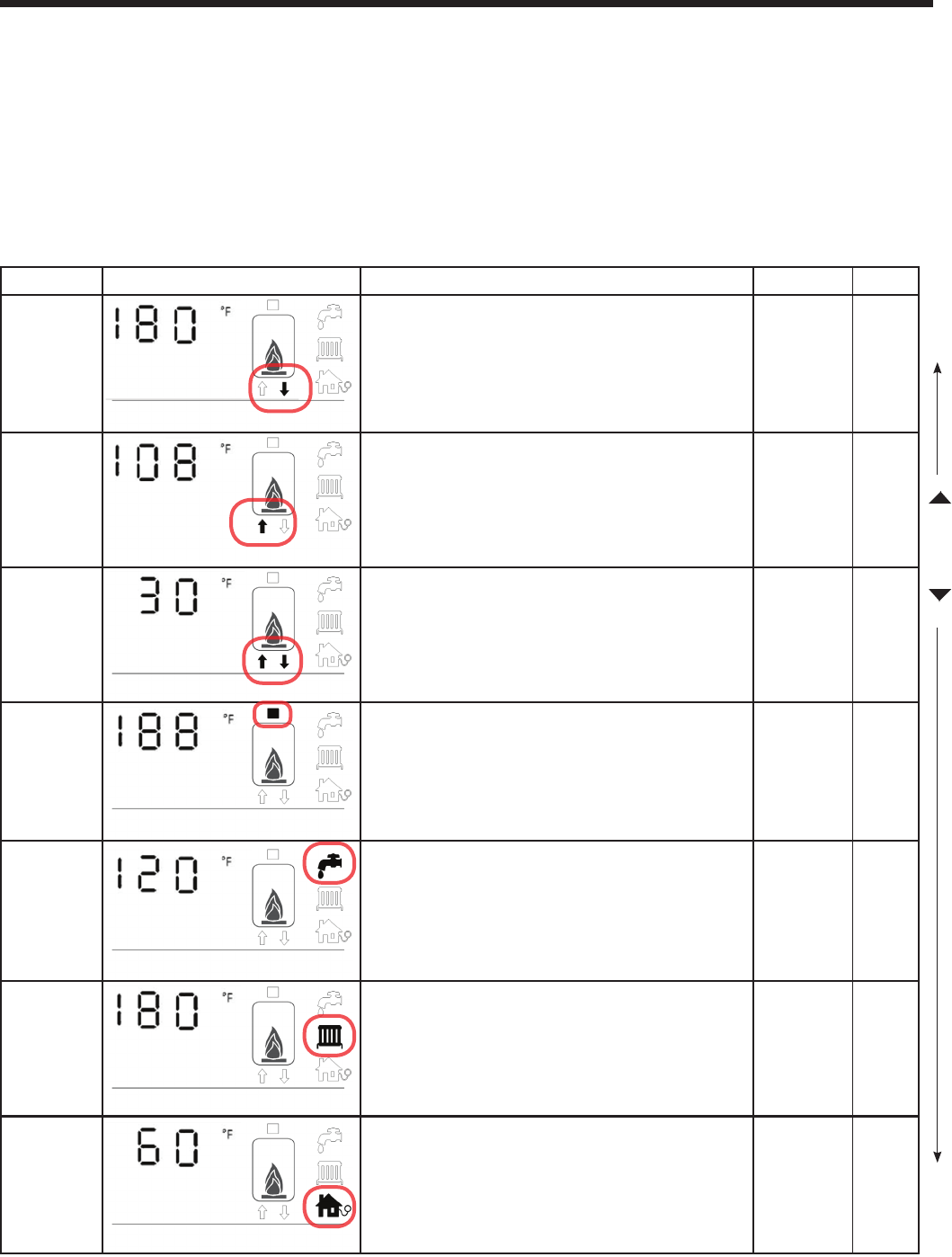
Page 33
Brute LX
8.3 USER Mode
The USER Mode is for a homeowner or service technician to adjust the most common operating parameters (See
Table 14). In the USER Mode, when the boiler is ON and operating normally, the USER can scroll Up and Down
using the Arrow Keys. Of the 7 viewable parameters, 4 can be adjusted (depending on if they are installed). The USER
adjustable parameters are the Outlet Temp, DHW Setpoint, and Outdoor Air Temp. If the System Setpoint is installed, it
can be adjusted, but then the Outlet Temperature can no longer be adjusted.
These parameters can be adjusted in the USER Mode by pressing the 'Select/OK' button (while in that parameter)
and then using the Up and Down arrows to set to the desired temperature.
Once the desired parameter is displayed, always press 'Select/OK' again to Save that setting.
Table 14. User Mode Displays.
Parameter Display Description Range Default
Outlet
Temp
Outlet Temperature is displayed as well as the 'darkened'
arrow pointing away from boiler icon.
The boiler setpoint (CH) can be changed by pressing 'Select/
OK' until 'Set' is displayed. Use the Arrows to adjust to the
desired Outlet temperature and then press 'Select' to Save.
45 - 189 130
Inlet Temp
Inlet Temperature is displayed as well as the 'darkened'
arrow pointing towards boiler icon
Delta T
Delta T is the temperature difference between the outlet
and inlet. The temperature difference is displayed and both
arrows below boiler icon become 'darkened'.
Stack
Temp
The Stack Temperature is displayed and the box on top of
the boiler icon is 'darkened'.
DHW
Setpoint
If the DHW Sensor is installed, Domestic Hot Water Temperature
is displayed and the the faucet icon will be 'darkened'. The
DHW setpoint can be changed by pressing 'Select' until 'Set'
is displayed on the left. Use the Arrows to adjust to the desired
temperature and then press 'Select' to Save.
68 - 189 120
System
Setpoint
If a System Sensor is installed, it will over-ride the Outlet
Temp, and the System Setpoint will be displayed and the
radiator (system) icon 'darkened'. The system setpoint can
be changed by pressing 'Select'. Use the Arrows to adjust to
the desired temperature and then press 'Select' to Save.
45-189 130
Outdoor
Air Temp
If the Outdoor Air Temperatue Sensor is installed, the house
icon (showing the outdoor sensor) becomes 'darkened' and
the Outdoor Air temperature is displayed.
Setpoint (
°
F)
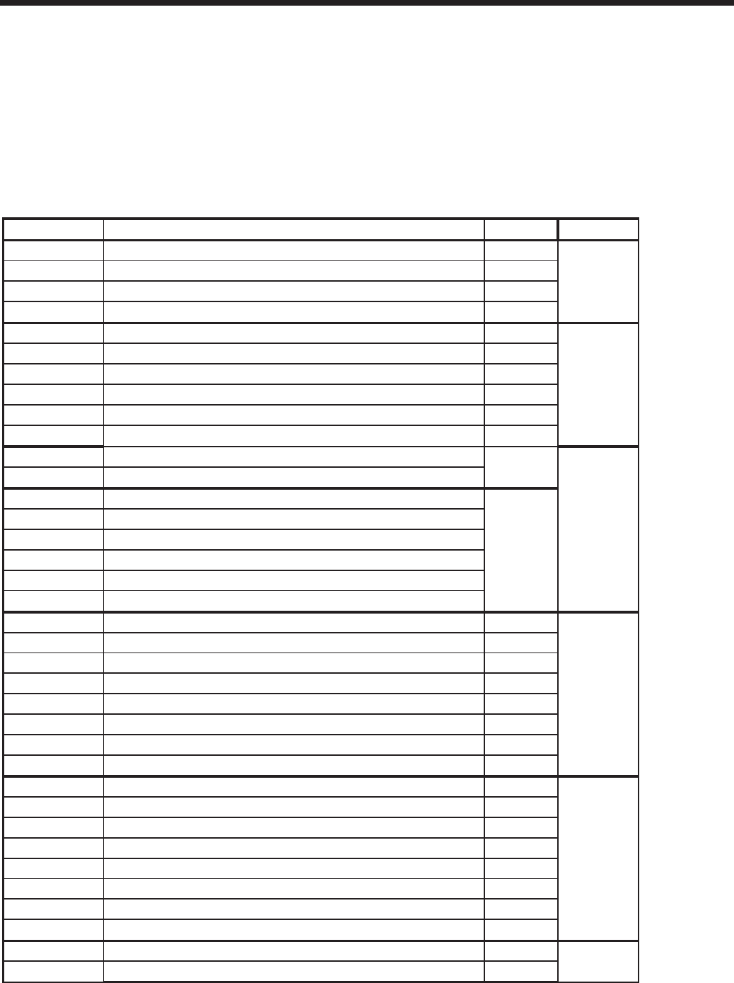
Page 34
BRADFORD WHITE CORP
.
Table 15. Installer Parameters (part 1)
Laars SIT Parameters
Page 1
USER MODE
PARAMETER Description DEFAULT Parameter
U000
DHW set point 120 °F USHWDEM
U001
CH set point 130 ° F US1SETP
U002
Installer Password 15 USPWD
U003
Display timeout 60 sec DUI1
U004
Unit temperature (F / C) ° F DUI2
D00 = dhw Temp
INSTALLER MODE
PARAMETER Description DEFAULT Parameter
P01 Service notification months 12 SERVICET
P02 Service notification hours since last service 8760 SERVICERUN
P03 Service notification cycles 500 SERVICEOP
P04 Timeout for service mode 180 secs
* displayed as seconds
TMAXSERV
P06 Cascade address and configuration -1 CASCADD
P07 Cascade temperature set point 140 ° F CASCREGSETP
P08 Cascade temperature offset 10 °
F CASCBLO
P09 Cascade temperature hysteresis from offset 20 ° F CASCHYS
P11 min time a bic must remain on or off 30 sec
shows 300 CASCMINTONOF
P12 min next on time 60 sec shows 600 CASCMINTNON
P23 Anti cycling time 30 sec TANTICY
P24 Anti cycling dropoff temperature on s2 10 °F ANTICYDROF
P25 0-10V to Power (fan speed) Enabled FUNCFLAG
P26 0-10V to outlet setpoint Disabled FUNCFLAG
P27 Alarm contact configuration Enabled
Enabled = NO / Disable
FUNCFLAG
P28 DHW demand blocks system pump Enable / Disable Disabled FUNCFLAG
P29 System Pump Always On Enable / Disable Disabled FUNCFLAG
P30 0-10V Input - Enable / Disable Enabled FUNCFLAG
P31 BMS Voltage at Minimum 2 VDC shows 200 V010AV
P32 BMS Voltage at Maximum 10 VDC shows 1000 V010BV
P33 On threshold Voltage 1 VDC shows 100 V010ON
P34 On hysteresis Voltage .5 VDC shows 50 V010HYS
P35 BMS Rate at Minimum Voltage 20% shows 200 V010APOW
P36 BMS Rate at Maximum Voltage 100% shows 1000 V010BPOW
P37 BMS Temperature Setpoint at Minimum Voltage 70 °F V010AC
P38 BMS Temperature Setpoint at Maximum Voltage 180 °F V010BC
P39 Postcirculation time CH pump 30 sec TPCIRCCH
P40 Postcirculation time DHW pump 30 sec TPCIRCHW
P41 Postcirculation time System pump 30 sec TPCIRCSYS
P42 Summer kick CH pump timer 20 sec SKICKCH
P43 Summer kick DHW pump timer 20 sec SKICKHW
P44 Summer kick System pump timer 20 sec SKICKSYS
P45 Delta T Setpoint for CH pump speed control 20 °F CHPMPSET
P46 Minimum output voltage for CH pump output 3.5 VDC shows 350 CHPMPMINV
P47 Differential Max Fan Speed for DHW demand 0 RPM
MAXFANHWDIFF
P48 Differential Maximum Fan Speed for CH demand 0 RPM MAXFANCHDIFF
ANTICYCLING & FLAGS User settingsService
Control
BMSCIRCULATION PUMPS
8.4 INSTALLER Mode
INSTALLER Mode is an extensive set of parameters
that can be changed to suit the individual installation and
should only be accessed by a trained service technician or
installer.
To access the INSTALLER Mode, hold
'Select/OK' and the down ˅ arrow key simultaneously
until U00 is displayed. Press 'Select/OK' again and then
release. Change the value to 15 and then press 'Select/OK'
again. The INSTALLER Mode Parameters will then
be accessible by pressing the Up or Down arrows.
(See Table 15 and Table 16)
To change the value of that parameter, press
Select/OK button again. The parameter will blink.
Pressing the Up or Down arrows will increase or
decrease the parameter value. The value will be
conrmed by pressing Select/OK button and the blink
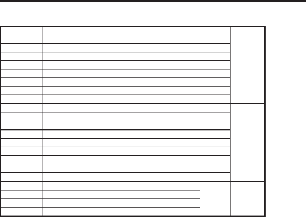
Page 35
Brute LX
Laars SIT Parameters
Page 2
P49 CH Priority time over DHW 0 min SWITCHOVTCH
P50 DHW Priority time over CH 55 min
* displayed as seconds
SWITCHOVTHW
P51 DHW tank setpoint 180 ° F HWTNKSETP
P52 Stop DHW tank demand offset 0 ° F HWDEMSTOP
P53 Start DHW tank demand offset 6 ° F HWDEMSTART
P54 Block DHW demand (combi) offset 12 ° F HWREGBLO
P55 Unblock DHW demand (combi) offset 20 ° F HWREGHYS
P56 Minimum user setting DHW set point 60 ° F CMINHW
P57 Maximum user setting DHW set point 140 ° F CMAXHW
P58 Frost protection s tart pump temperature 45 ° F FROSTPMP
P59 Frost protection start burner temperature 37 ° F FROSTBURN
P60 Frost protection stop burner hysteresis 5 ° F FROSTHYS
P61 Low outdoor air temperature for heat curve 25 ° F HC1AX
P62 High setpoint for heat curve 180 ° F HC1AY
P63 High outdoor air temperature for heat curve 70 ° F HC1BX
P64 Low setpoint for heat curve 120 ° F HC1BY
P65 Outside temperature disabling CH demand 90 ° F HC1OUTLIM
P66 Outside temperature disabling CH hysteeresis 5 ° F HC1OUTHYS
P70 Minimum user setting CH set point 32 ° F CMINCH
P71 Maximum user setting CH set point 190 ° F CMAXCH
P72 Block offset CH demand 10 ° F CH1BLO
P73 Block hysteresis CH demand 20 ° F CH1HYS
DHW SETTINGS
TEMP.
SETTINGS
FROST PROTECTION &
OUTDOOR RESET
8.5 SERVICE Mode
The Brute LX Series of appliances has been
designed with a SERVICE Mode of operation
intended for servicing and troubleshooting of the
unit by a Brute LX trained service technican.
‘SERVICE' Mode can be activated by pressing
and holding the 'Select/OK' button and ‘Up Arrow’
simultaneously for ve seconds. With an active call
for heat, the boiler will light and run at 100% of ring
rate. The boilers input can be adjusted in 20% rate
increments by pressing the ‘Up’ or ‘Down’ Arrows. You
can also toggle between Maximum Rate and Minimum
Rate by pressing the 'Select/OK' button. To exit
SERVICE Mode depress and hold the 'Select/OK' button
for ve seconds.
Table 16. Installer Parameters (part 2)
8.6 Modulation Control
The control uses a PID algorithm to adjust the ring
rate of the boiler as the control point is approached.
The goal of the control is to operate at a minimum
ring rate to match the load on the appliance.
8.7 Pump Control
The boiler pump is active anytime there is a call for
heat applied to the control. When there is a central
heat call the system pump relay is active. If there
is a DHW call while the central heat call is active
the system pump turns off. This happens because of
domestic hot water priority, which forces the control
to satisfy the domestic water demand prior to the
hydronic demand. When the last heat demand is
satised the boiler pump enters an overrun time.
NOTE: There must be an active call for heat given
to the appliance for Service Mode to allow the
boiler to start. When the Service Mode is exited,
the boiler will continue to run until the call is either
satised or removed.
will stop.
The parameter value will return to the previous
setting if you press the Cancel button.
Otherwise, Exit INSTALLER Mode by pressing
and holding 'Select/OK' for 3 seconds.

Page 36
BRADFORD WHITE CORP
.
8.8 High Limit
The control uses a dual thermistor sensor to monitor the
Brute LX's maximum temperature. The high limit sensor
is installed in the outlet water. A dual thermistor sensor
is used, so that the two temperatures can be monitored
and compared to conrm accuracy. The control will
automatically reduce the ring of the Brute LX to
prevent the high limit from tripping. The high limit
setpoint is not adjustable.
8.9 Stack Temperature
The stack temperature is a dual thermistor sensor
and is limit rated. The control compares each of the
temperature readings to determine accuracy. The stack
sensor is used as a limiting feature to avoid excessive
temperatures in the venting.
8.10 Domestic Hot Water Temperature
The domestic hot water temperature sensor is used to
control the DHW temperature. The DHW setpoint can
be adjusted through the Base / Home state and the User
Mode. On LX ‘C’ or Combi models, the DHW sensor
is pre-installed in the DHW exchanger. On LX ‘H’ or
Heat models the DHW can be can be controlled by an
aquastat or optional DHW sensor installed in an indirect
tank.
SECTION 9.
OPERATION Modes
To access the setup parameters for conguring different
Operation Modes, the installer level password most be
used according to section 8.4.
9.1 Hydronic Heating Demand
When using the Brute LX for hydronic heating a call
for heat must be supplied to the "T-T or Interlock"
terminals. Once the call is supplied the control energizes
the boiler pump, the system pump relay, shifts the
3-way valve position and begins the ignition process.
The ignition process consists of a prepurge, trial for
ignition, and run period. The prepurge period starts
once the fan RPM reaches a preset level. The trial for
ignition period follows. The trial for ignition period lasts
4 seconds during which the direct spark ignition system
and gas valve are energized. At the end of the trial for
ignition period the ame signal is compared with the
preset ame threshold value. If the ame signal is higher
than the ame threshold the Brute LX enters "run". If
the ame signal is below the threshold the Brute LX
returns to prepurge and starts the ignition process over.
In "run" the Brute LX monitors the ame signal, call for
heat, safeties, and water temperatures and modulates as
needed between 100% and 20% of rate to satisfy the call
for heat.
9.2 Hydronic Heating with Outdoor Reset
Outdoor reset varies the control setpoint based on the
outdoor temperature. The reset function works as shown
in Figure 25. When the outdoor air temperature reaches
P61 "high outdoor temperature setpoint” the control
point setting is adjusted to P62 “low boiler temperature
setpoint”. When the outdoor air temperature reaches P63
“low outdoor temperature setpoint” the control setpoint
is adjusted to P64 “high boiler temperature”.
9.3 Hydronic Heating Using External
Modulation Control (BMS)
The Brute LX can accept a 0-10 VDC input to
integrate with a building management system or external
modulating control. Utilizing Installer Parameters P31
“BMS Voltage at minimum” and P32 ”BMS voltage
at maximum” the installer can set the minimum and
maximum input voltages. By default this input is
enabled but can be disabled using Installer Parameter
P30 “0-10v Input Enable / Disable”.
The Brute LX can use an external 0-10VDC signal to
control its fan speed (modulation rate), or to control its
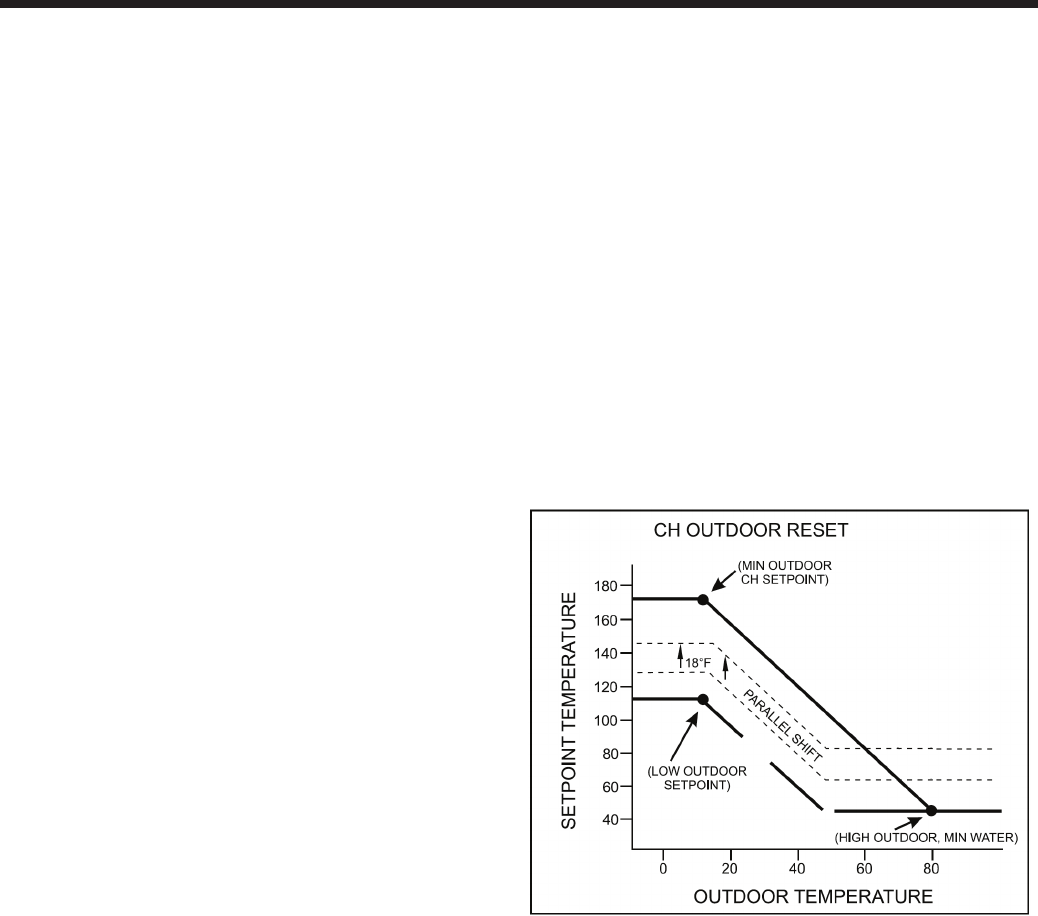
Page 37
Brute LX
outlet setpoint. The 0-10V signal may also be used to
create a heat demand eliminating the need to supply a
separate “TT call”.
9.3.a External Signal to Control Modulation.
Installer Parameter P25 “0-10V to Power (fan speed)”
– This is the default 0-10VDC conguration in which
the external signal directly corresponds to fan speed
or ‘boiler power’ In this mode, the call is initiated by
the 0-10v input based on Installer Parameters P33 “On
threshold voltage” and P34 “Off hysteresis voltage”.
The modulation power can also be scaled with P35
“BMS rate at minimum voltage” and P36 “BMS rate at
maximum voltage”.
9.3.b External Signal to Control Setpoint.
Installer Parameter P25 “0-10v BMS modulation
control” must be disabled – In this mode the 0-10VDC
input directly controls the boiler's outlet temperature.
Set the parameters using the Installer Parameters P37
“ BMS Temperature setpoint at minimum voltage” and
P38 “BMS temperature setpoint at maximum voltage”
9.3.c External Signal Initiates Heat Demand
In this mode P26 “0-10V BMS Thermostat Demand
Required” must be disabled to eliminate the need for
a separate “TT Call”. This allows a heat demand to be
created every time the 0-10V signal exceeds P33 “BMS
On Volts”. The heat demand will remain until the 0-10V
signal drops below P33 “BMS On Volts” – P34 “BMS
Demand Off Differential Voltage”
9.4 Warm Weather Shutdown
Warm weather shutdown overrides a central heat
call when the outdoor air temperature is greater than
the warm weather shutdown setpoint. Warm weather
shutdown is always active when there is an outdoor
sensor attached to the control. The warm weather
shutdown setpoint can be adjusted in Installer mode,
using P65 “CH outdoor Air Shutdown Temperature” and
P66 “CH Outdoor Air Shutdown Differential”.
9.5 Domestic Hot Water Demand
9.5.a Combi Boiler DHW
For Combi units (BLXC), DHW demand is triggered
by a ow sensor located near the DHW cold water inlet.
When water begins to ow (open faucet, shower, etc.),
the boiler will re, based on the water temperature
requirements. It may cycle on and off under very low
ow rates. Minimum ow is 0.5 gpm.
9.5.b Boiler only DHW aquastat demand
For Boiler only units (BLXH), an indirect water heater
can be piped-in. An aquastat in the indirect water heater
connected to terminals 7 and 8 will signal demand for
DHW. In this demand mode the boiler will modulate on
the outlet water temperature sensor and use P51 “DHW
setpoint (S1 – Tank) as the setpoint.
9.5.c Boiler only DHW sensor demand
An optional DHW sensor (Bradford White PN
E2337501) can also be installed in an indirect water
heater connected to terminals 9 and 10 to initiate demand.
In this mode the tank sensor will control demand and
modulation based on the DHW setpoint. In the case of
indirect heaters the boiler will also modulate on the outlet
water temperature sensor and use P51 “DHW setpoint
(S1 – Tank) as the setpoint.
The service person should note the minor wiring
differences on Figure 22.
9.6 Domestic Hot Water Priority
DHW priority is used to allow the CH call to be
interrupted when there is a DHW call. This allows
the boiler to use the full capacity to satisfy hot water
demands without interruptions. From the factory the
default settings give priority to DHW for 55 minutes
before switching to satisfy the CH demand. To adjust
navigate to installer parameter P50 “ DHW priority
over CH” and adjust the time as required.
At the end of the DHW priority period the
boiler will switch to CH priority to supply heat to the
building. The boiler remains in this state until P49,
“CH priority time over DHW” expires. To adjust
navigate to installer parameter P49 and adjust the time
as required.
Figure 25. Outdoor Reset Setpoint Temperatures.

Page 38
BRADFORD WHITE CORP
.
9.7.1 Cascade Manual Conguration
In some applications it may be necessary to congure the
cascade system manually. To do this, the boilers should
be wired as shown in the Auto Cascade section of the
manual. Then each individual control in the cascade
must have a specic address assigned by adjusting P06
“ Cascade address” on each boiler. To start, identify
the boiler that will be the “master” boiler. Navigate to
parameter P06 “cascade address” set to “0” and press
“Select” (do NOT press and hold select). Then press and
hold select.
Repeat this process for each boiler in the cascade setting
each address to a unique number.
The last step is to adjust all of the setpoints for the
installation application as shown in the Auto cascade
section of the manual.
9.7 Cascade Auto Conguration
To operate up to 8 boilers in cascade, the boilers
must be “daisy chained” together using Modbus
terminals A, B and GND, located on the boilers
terminal block. The wiring should be completed with at
least three wire shielded cable with ground. The ground
wire should be connected to a suitable chassis ground
on one end of the daisy chain only. Wire each boilers
terminal A in series with the next boilers terminal A
until all are connected. Repeat this process for Terminal
B and GND.
To congure the control system, identify which
boiler is going to be the “master” boiler for the cascade
system and navigate to installer parameter P06,
“Cascade Address”. Set the address to “0” and press
and hold “select”. When “auto cfg” appears on the
display press “select” to start the auto conguration
process. The auto conguration process will nd all
boilers connected to the “master” boiler and assign
addresses. When auto conguration is complete the
display should show “boilr #” where # is the total
number of boilers found in the cascade system.
The nal steps are to set the individual setpoints
in the cascade system, which include P07 “Cascade
Setpoint”, P08 “Cascade off Hysteresis” and P09
“Cascade on hysteresis”. These variables must be set
to the appropriate values for the installation. When
setting P09 “cascade on hysteresis” the value should
NOT be less than P08 “Cascade off Hysteresis” as
P09 references the off point (P07+ P08) as the starting
point for the on hysteresis. An example of this is shown
below.
Correct settings:
P07 = 120°F
P08 = 10°F
P09 = 20°F
With these setting the modulation point is 120°F
The off point is 120°F + 10°F = 130°F
The on point is 130°F – 20°F = 110°F
Incorrect settings:
P07 = 120°F
P08 = 10°F
P09 = 5°F
With these setting the modulation point is 120°F
The off point is 120°F + 10°F = 130°F
The on point is 130°F – 5°F = 125°F
In this case the boiler is turning back on prior to
reaching the modulation point, which could lead to
short cycling.
Page 39
Brute LX
the highest point in the circulating loop, then the
system is ready for operation.
12. Refer to local codes and the make-up water valve
manufacturer’s instructions as to whether the make-
up water valve should be left open or closed.
13. After placing the unit in operation, the ignition
system safety shutoff device must be tested.
First, shut off the manual gas valve, and call the
unit for heat. Main gas terminals will be energized,
attempting to light, for four (4) seconds, and then
will de-energize. The unit will go into lockout after
the required number of trial for ignition periods.
Second, turn the power off, press the manual reset
button on the boiler control, or the user display,
open the manual gas valve and allow the unit to
light. While the unit is operating, close the manual
gas valve and ensure that power to the main gas
valve has been cut.
14. Within three (3) days of start-up, recheck all air
bleeders and the expansion tank as described in
Steps 4 and 8 above.
Important Note: The installer is responsible for
identifying to the owner/operator the location of all
emergency shutoff devices.
WARNING
Do not use this appliance if any part has been under
water. Immediately call a qualied service technician
to inspect the appliance and to replace any part of
the control system and any gas control that may have
been under water.
10.2 Starting the Burner after Set Up
Initial setup must be checked before the unit is put
in operation. Problems such as failure to start, rough
ignition, strong exhaust odors, etc. can be due to
improper setup. Damage to the boiler resulting from
improper setup is not covered by the limited warranty.
10.2.1 Burner Operation
REQUIRED TOOLS: Allan Key Set (English), Screw
drivers, and combustion analyzer.
1. Using this manual, make sure the installation
is complete and in full compliance with the
instructions and all local codes.
2. Determine that the appliance and system are lled
with water and all air has been bled from both.
Open all valves.
3. Observe all warnings on the Operating
Instructions (Start Up / Shut Down
Instruction ) Decal, located on the back of
the Top Front Cover, and turn on gas and
electrical power to appliance.
SECTION 10.
Set Up Instructions
10.1 Filling the Boiler System
1. Ensure the system is fully connected. Close all
bleeding devices and open make-up water valve.
Allow system to ll slowly.
2. Move manual lever on 3-way valve actuator to
"open" position, allowing air to purge from boiler
loop. Valve is normally in DHW position until
there is a call for Central Heat via "T-T" contacts. If
make-up water pump is employed, adjust pressure
switch on pumping system to provide a minimum
of 12 psi (81.8 kPa) at the highest point in the
heating loop.
3. If a water pressure regulator is provided on the
make-up water line, adjust the pressure regulator
to provide at least 12 psi (81.8 kPa) at the highest
point in the heating loop.
4. Open bleeding devices on all radiation units at the
high points in the piping throughout the system,
unless automatic air bleeders are provided at such
points.
Note that there is an air bleed located on the
left side of Brute LX, on top of the jacket.
5. Cycle the boiler pump on and off 10 times, 10
seconds on and 10 seconds off to remove all air
from the heat exchanger. Then run system and
appliance pump for a minimum of 30 minutes with
the gas shut off.
6. Using manual lever located on left side of 3-way
valve actuator, move from "open" position back to
closed position repeatedly. This process forces air
out of the internal DHW loop.
WARNING
Failure to remove all air from the heat exchanger could
lead to property damage, severe injury or death.
7. Recheck all air bleeders as described in Step 4.
8. Start up boiler according to the procedure in this
manual. Operate the entire system, including the
pump, boiler, and radiation units for one (1) hour.
9. Shut down the entire system and vent all radiation
units and high points in the system piping, as
described in Step 4.
10. Close make-up water valve and check strainer in
pressure reducing valve for sediment or debris from
the make-up water line. Reopen make-up water
valve.
11. Check gauge for correct water pressure and also
check water level in the system. If the height
indicated above the boiler insures that water is at
Page 40
BRADFORD WHITE CORP
.
4. Brute LX will enter the start sequence. Blower and
pump will energize for pre-purge, then the ignition
sequence starts. After all safety devices are veried,
the gas valve opens. If ignition doesn’t occur, turn
off the Brute LX, check that there is proper gas
supply. Wait 5 minutes and start the unit again.
5. Turn Brute LX on.
6. After placing the appliance in operation, the
Burner Safety Shutoff Device must be tested:
(a) Close gas shutoff valve with burner operating.
(b) Flame will go out and blower will continue to run
for the post purge cycle. One or three additional
attempts to light will follow including pre-purge,
ignitor on, valve/ame on and post purge. Ignition
will not occur as the gas is off. The ignition control
will lockout.
(c) Open gas shutoff valve. Reset the boiler control
by pressing the RESET button on the control or
on the display. Restart the appliance. The ignition
sequence will start again and the burner will start.
The appliance will return to its previous mode of
operation.
CAUTION
Should any odor of gas be detected, or if the gas
burner does not appear to be functioning in a normal
manner, CLOSE MAIN SHUTOFF VALVE. Do not
shut off switch. Contact your heating contractor, gas
company, or factory representative.
10.2.2 Boiler Setup and Adjustment
1. Measure the CO2 in the ue products at high re.
The Brute LX can be forced to high re to allow
for easier setup. Refer to Section 8 for instructions
on how to access the forced rate menu. The CO2
readings should be between the range shown in
Table 17. If the CO2 is not within the range shown,
adjustments may be made. To adjust the high re
CO2, locate the high re adjuster screw (see Figure
26). Using a 2.5 mm Hex wrench, slowly make
adjustments in 1/16 of a revolution increments
until the CO2 is within the range identied.
(see Figure 26)
2. Measure the CO2 in the ue products at low re.
Brute LX can be forced to low re to allow for
easier setup. Refer to Section 8 for instructions on
how to access the forced rate menu. CO2 readings
should be between the range shown in Table 17. If
the CO2 is not within the range shown, adjustments
may be made. To adjust the low re CO2, locate
the low re adjuster screw. Using a 4 mm Hex
wrench, slowly make adjustments in 1/16 of a
revolution increments until the CO2 is within
the range identied. (see Figure 26)
3. Repeat steps 1 and 2 to conrm that the CO2 ranges
are within the required ranges. High and Low
Fire CO2 settings should be approximately equal.
Adjust if necessary.
If any CO2 readings cannot be adjusted to the
specied ranges (see Table 17), please consult the
factory for further information.
WARNING
Improper adjustment may lead to poor combustion
quality, increasing the amount of carbon monoxide
produced. Excessive carbon monoxide levels may
lead to personal injury or death.
10.3 Shutting Down Brute LX
1. Turn off the main electrical disconnect switch.
2. Close all manual gas valves.
3. If freezing is anticipated, drain Brute LX and be
sure to also protect building piping from freezing.
All water must be removed from heat exchanger
and condensate trap or else damage from freezing
may occur.
This step to be performed by a qualied service person.
10.4 To Restart Brute LX
If drained, go back to Section 10 in this manual for
proper lling and purging, prior to continuing.
1. Turn off the main electrical disconnect switch.
2. Close all manual gas valves.
3. WAIT FIVE (5) MINUTES.
4. Set the aquastat or thermostat to its lowest setting.
5. Open all manual gas valves.
6. Reset all safety switches (pressure switch, manual
reset high limit, etc.).
7. Set the temperature controller to the desired
temperature setting and switch on electrical power.
8. Burner will go through a prepurge period and
ignitor warm-up period, followed by ignition.
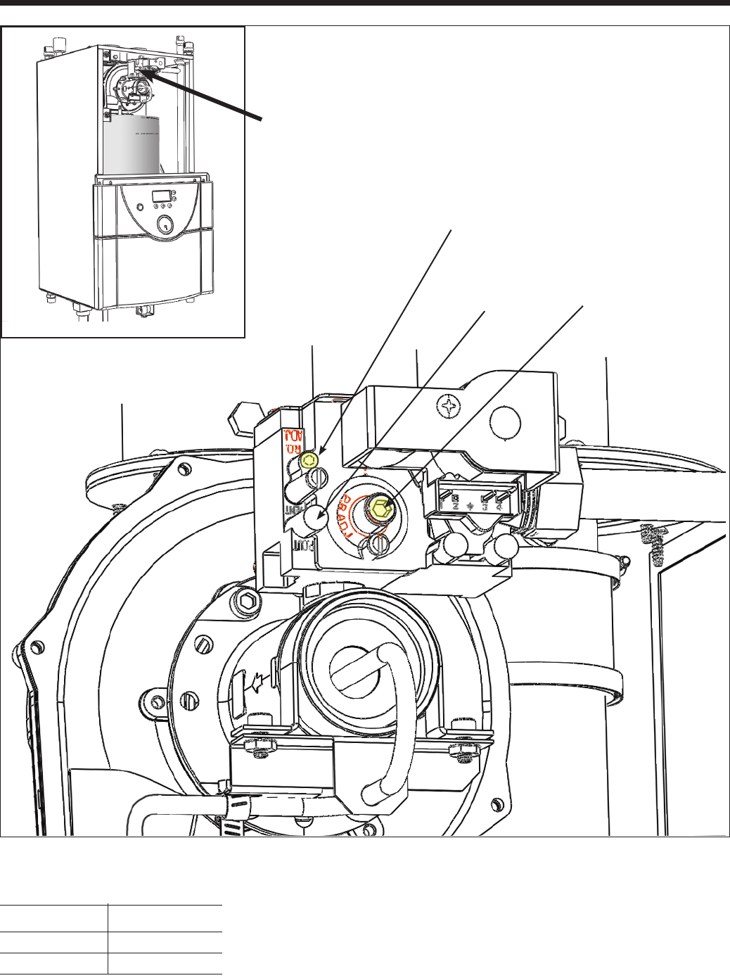
Page 41
Brute LX
GAS TYPE CO2 (%) RANGE
)
Natural 8.9 __ 9.9
Propane 9.9
__ 10.9
Table 17. CO2 Range and Pressure Settings.
Figure 26. Adjustment Screws and Settings for CO2
Manifold
Pressure
Screw
(under cap)
High-re
setting
Adjustment Screws on
Gas Valve
Close door rst, before
measuring CO2 Range
Low-re
setting
Note: High and Low Fire CO2 settings
should be approximately equal.
Page 42
BRADFORD WHITE CORP
.
SECTION 11.
Maintenance
WARNING
Disconnect all power to the appliance before
attempting any service to the appliance. Contact with
electricity can result in severe injury or death.
11.1 System Maintenance
(yearly, unless otherwise noted)
1. If a strainer is employed in a pressure reducing
valve or the piping, clean it every six months.
2. Inspect the venting system for obstruction or
leakage at least once a year. Periodically clean the
screens in the vent terminal and combustion air
terminal (when used).
3. Keep the appliance area clear and free from
combustible materials, gasoline, and other
ammable vapors and liquids.
4. If the appliance is not going to be used for extended
periods in locations where freezing normally
occurs, it should be isolated from the system and
completely drained of all water.
5. Low water cutoffs, if installed, should be checked
every year. Float type low water cutoffs should be
ushed periodically.
6. Inspect and clean the condensate collection system
yearly.
7. When a means is provided to neutralize condensate,
ensure that the condensate is being neutralized
properly.
8. Removal of burner and inspection of combustion
coil and ue passages is required at least once a
year. Clean with a soft bristle brush / vacuum or
wash with water if necessary. Sooting and buildup
on the coils is an indication of improper set up and
poor combustion. Determine the cause and make
corrections.
9. Inspect the vent system and air intake system, and
ensure that all joints are sealed properly. If joints
need to be resealed, completely remove existing
Garlock sealing material, and clean with alcohol.
Apply new sealing material, and reassemble.
11.2 Appliance Maintenance and
Component Description
Use only genuine Bradford White replacement parts.
Brute LX gas and electric controls are engineered for
long life and dependable operation, but the safety of
equipment depends on their proper functioning. Only
a qualied service technician should inspect the basic
items listed below every year:
a. Appliance control f. Flow switch
b. Automatic gas valve g. Low water cutoff
c. Pressure switches h. Burner
d. Blower i. Heat exchanger
e. Pump
11.2.1 Burner
Check the burner for debris. Remove the blower
assembly to access the burner. Remove the 4 bolts
connecting the blower Pull burner up and out. Clean
burner, if necessary, by blowing compressed air from
the outside of the burner into the center of the burner,
and wipe the inside of the burner clean with glass
cleaner. A dirty burner may be an indication of improper
combustion or dirty combustion air. Determine the
cause, and correct. If damaged, replace the burner gasket
when replacing the burner.
NOTE: When installing the burner, make sure the ange
is aligned with the mating surface, as each is keyed to
control t.
11.2.2 Appliance Control
Brute LX has an integrated control that incorporates
manual reset high limit control, operating temperature
control, modulating control, ignition control, outdoor
reset control, pump control and many other features. If
any of these features are thought to be defective, please
consult the factory for proper trouble shooting practices
prior to replacing the control. If control replacement is
required, turn off all power to the appliance and shut off
all manual gas valves to the appliance. Remove the front
door to the appliance and the control panel plastic bezel.
Remove all wire connections from the control board.
The control board connections are keyed to only allow
connection in the proper location, but proper handling
techniques should be used to avoid damage to the
wiring or connectors. To remove the control push in on
the two tabs on the left side of the board to unlatch the
clips from the control panel. Rotate the control around
ATTENTION
Au moment de l'entretien des commandes, étiquetez
tous les ls savant de les débrancher. Les erreurs de
câblage peuvent nuire au bon fonctionnement et être
dangereuses. S'assurer que l'appareil fonctionne
adéquatement une fois l'entretien terminé.
CAUTION
Label all wires prior to disconnection when servicing
controls. Wiring errors can cause improper and
dangerous operation. Verify proper operation after
servicing.
Page 43
Brute LX
the fastening points on the right side of the control to
remove the hooks from the control panel. To replace
the control repeat the steps above in the reverse order
making sure to connect all wires in the proper location.
Place the appliance in operation following the steps
outlined in Section 10.
11.2.3 Ignitor Assembly
The ignitor assembly is a two rod system that consists
of a ground rod and a sense rod. To remove the ignitor
assembly, shut off the 120 Volt power supply to the
appliance. Turn off all manual gas valves connecting the
appliance to the main gas supply line. Remove the front
door of the boiler to gain access to the ignitor assembly.
Remove the two wires connected to the assembly. Then
remove the two bolts connecting the ignitor assembly
to the burner door. Remove and replace the old ignitor
assembly gasket. Reinstall a new ignitor assembly in
the reverse order if the old assembly is determined
defective. Replace gasket if necessary.
11.2.4 Flame Sensor
The ame sensor is a single rod system. To replace the
ame sensor electrode, shut off the 120 Volt power
supply to the boiler. Turn off all manual gas valves
connecting the boiler to the main gas supply line.
Remove the front door of the boiler to gain access to
the ame sensor electrode. Remove the ame sensor
wire from the electrode. Remove the two bolts fastening
the electrode to the boiler top. Remove and replace the
old ame sensor gasket. Reinstall a new ame sensor
electrode in the reverse order if the old electrode is
determined defective.
CAUTION
Igniters and sensors get hot and
can cause burns or injury.
11.2.5 Blower
The combustion air blower is a high-pressure centrifugal
blower with a variable speed motor. Speed of the motor
is determined by the control logic. 120 Volts remain on
to the blower at all times. If a blower change is required,
turn off the 120 Volt power and gas supply to the unit.
Take the front panel off. Disconnect the 120 Volt and
control signal connections from the blower. Disconnect
the bolts connecting the venturi to the blower housing.
Disconnect the fan outlet bolts from the burner door
blower arm. If the fan is determined to be defective
replace the existing fan with a new one reversing the
steps above. Make sure to install all of the required
O-rings and gaskets between the blower arm and the
blower and blower face and venturi ange.
11.2.6 Heat Exchanger Coils
Black carbon soot buildup on the internal surfaces of
the heat exchanger is caused by one or more of the
following; incomplete combustion, combustion air
problems, venting problems and heater short cycling.
Soot buildup or other debris on the heat exchanger may
restrict the ue passages.
If black carbon soot buildup on the heat exchanger is
suspected, disconnect electrical supply to the unit, and
turn off the gas supply by closing the manual gas valve
on the unit. Access the heat exchanger through the
burner at the top of the boiler, and inspect the tubing
using a ashlight and a mirror. If there is a buildup of
black carbon soot or other debris on the heat exchanger,
clean per the following:
CAUTION
Black carbon soot buildup on a dirty heat exchanger
can be ignited by a random spark or ame. To prevent
this from happening, dampen the soot deposits with
a wet brush or ne water spray before servicing the
heat exchanger.
1. Shut off the 120 Volt power supply to the boiler
2. Turn off all manual gas valves connecting the boiler
to the main gas supply line.
3. Disconnect all blower wiring and gas valve piping.
4. Remove the four bolts connecting the blower ange
to the burner ange.
5. Remove the burner assembly from the heat
exchanger.
6. Disconnect the condensate drain line.
7. Attach a longer hose to drain and run to a bucket.
8. Clean the heat exchanger by brushing light
accumulations of soot and debris. Use a brush
with soft bristle (non metal) to avoid damaging the
surface of the heat exchanger tubes or refractory.
CAUTION
Be careful not to damage refractory material located
at top and bottom of heat exchanger.
9. Once the tubes have been brushed clean rinse the
tubes and combustion chamber with a small amount
of water to rinse all of the debris out of the bottom
of the ue collector and into the longer condensate
trap line, which is being diverted into a separate
container.
NOTE: The Warranty does not cover damage caused
by lack of required maintenance, lack of water ow,
or improper operating practices.
Page 44
BRADFORD WHITE CORP
.
WARNING
Failure to rinse the debris from the heat exchanger
and temporary drain line may lead to clogged
condensate lines, traps and neutralizers. Condensate
pumps (if used) may also be damaged from the
debris left behind, possibly causing property damage.
10. Install all components removed in the reverse
order to place the appliance back in operation.
Make sure all gaskets are in place as components
are installed. Replace any damaged gaskets. Do
NOT reuse damaged gaskets.
11. Place the appliance in operation according to
Section 10 checking all gas connections for leaks.
Conrm all fasteners are tight.
11.2.7 Gas Conversion
There are no parts or orices required for the gas
conversion of the Brute LX. But if a gas conversion
is performed, the unit must be identied with the
appropriate gas labels and a conversion sticker to allow
technicians performing maintenance in the future to
properly identify the gas type of the appliance. These
stickers are included with the boiler during shipment.
Conversion to/from LP Gas Instructions:
1. Open the front covers as described in Section 1
and Figure 1.
2 Place "Propane Gas" sticker over the "Natural
Gas" sticker (or vice versa) where the gas supply
line enters the appliance.
3. Fill out gas conversion sticker with all of the
required information and place adjacent to the
Rating Plate sticker (which is behind the center
door panel).
4. Conrm that the gas supply is turned on.
5. Start boiler per lighting procedure shown on inside
front cover or side of appliance.
6. With a combustion analyzer, check CO2 levels at
both maximum and minimum input.
Refer to sections Figure 26 and Table 17 of this
manual for the proper adjusting procedures.
7. Close all front covers.
WARNING
Serious injury or death could occur if CO2 levels are
not adjusted properly.
__________________________________________
NATURAL
NATUREL
H0011700F
1.0"
3.0"
WARNING
This conversion shall be installed by a qualied
service agency in accordance with the manufacturer's
instructions and all applicable codes and
requirements of the authority having jurisdiction. If
the information in these instructions is not followed
exactly, a re, an explosion or production of carbon
monoxide may result causing property damage,
personal injury or loss of life. The
qualied service agency is responsible
for the proper and complete installation
of this kit. The installation is not proper
and complete until the operation of the
converted appliance is checked as specied in the
manufacturer's instruction supplied with the kit.
AVERTISSEMENT
Ce conversion doit être installé par un organisme de
service conformément aux instructions du fabricant
et tous les codes et les exigences de l'autorité
compétente. Si les informations contenues dans ces
instructions n'est pas suivi à la lettre, un incendie,
une explosion ou de la production de monoxyde
de carbone mais résultat causant des dommages
matériels, des blessures ou des pertes de vie. Le
service est responsable pour la bonne et complète
l'installation de ce kit. L'installation n'est pas correcte
et complète jusqu'à ce que le fonctionnement de
l'appareil converti est vériée comme spécié dans le
manuel d'instruction fourni avec le kit.
Figure 27. Natural Gas Sticker
Figure 28. Propane Gas Sticker
This boiler has been converted to use:
3.50"
2.00"
20 Industrial Way
Rochester, NH 03867
H2200500D
Converted
by:
Date:
Natural Gas
Propane
Figure 29. Gas Conversion Sticker

Page 45
Brute LX
SECTION 12.
Troubleshooting
12.1 Sequence of Operation
Brute LX is a cold start appliance that should start only
on a call for heat from a tank aquastat, room thermostat,
zone valve end switch or other space temperature
control device (ow switch for DHW).
1. Upon a call for heat: (a) the internal pump and
system pump will start; (b) the blower will begin a
short pre-purge.
2. Following the prepurge cycle the direct spark
ignition will spark and will begin a 4 second
trial for ignition. The unit is allowed one or three
ignition retries.
3. The gas valve will then be energized and a reduced
45% rate ignition will occur. The unit will remain
in the reduced rate start-up period for
ten (10) seconds.
4. After the reduced rate start time is over, the
unit will be in normal operation. Firing rate
will modulate based on the heating load via the
temperature controller settings and readings.
5. When the call for heat is complete, or the unit
reaches its setpoint temperature, the gas valve will
close, and the fan will continue to run for its post-
purge. If a pump delay time is used, the pump will
continue to run for the specied amount of time
(adjustable from 0.1 to 10 minutes).
12.2 Short Cycling
Because Brute LX is a modulating boiler, and it's input
will decrease when there is a reduction in heating
load, short cycling is greatly reduced. If the heating
load drops below the minimum input of the boiler for
an extended period, the boiler will have a tendency to
short cycle. This can be a symptom of improper control
or piping layout. When in DHW mode under low load
conditions, the boiler will normally cycle more often,
but should not cycle frequently during call for central
heating.
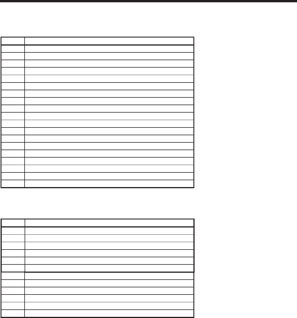
Page 46
BRADFORD WHITE CORP
.
LOCKOUT CODES
CODE DESCRIPTION
E001 Memory error lockout
E002 Fan speed error
E003 Flame present when not in run
E004 Outlet auto-reset hi limit
E005 Water pressure switch error
E006 Safety Switch - TBD
E007 Optional low-water cutoff error
E008 Field Interlock error
E009 Blocked vent switch (175C, 175H only at this time)
E010 Blocked vent / fan proving switch error
E011
Lockout due to 3 consecutive flame losses during run
E012 Lockout due to 3 consecutive failed ignitions
E013 Flue high temperature
E014 Outlet high temperature (manual reset hi limit)
E015 Flue sensor drift too high
E016 Outlet sensor drift too high
E017 Flue sensor error
E018 Outlet sensor error
E019 Inlet sensor error
BLOCKING CODES (may reduce input rate/heating capacity)
CODE DESCRIPTION
b01 General (e.g. if setpoint reached or other not specified)
b02 Anticycling
b03 Outlet temperature too high
b04 Delta T (Outlet-Inlet) temperature too high
b05 Flue temperature too high
b06 Line voltage too low
NOTIFICATION CODES
CODE DESCRIPTION
n01 Fan speed limited due to flue gradient not detected
n02 Fan speed limited due to outlet temperature
n03 Fan speed limited due to delta T (Outlet - Inlet)
n04 Fan speed limited due to flue temperature
n05 DHW sensor not present in combi boiler. HW call will be blocked
n06 Outdoor sensor not preset
Table 18. Error Codes
12.3 Error Codes - See Table 18.

Page 47
Brute LX
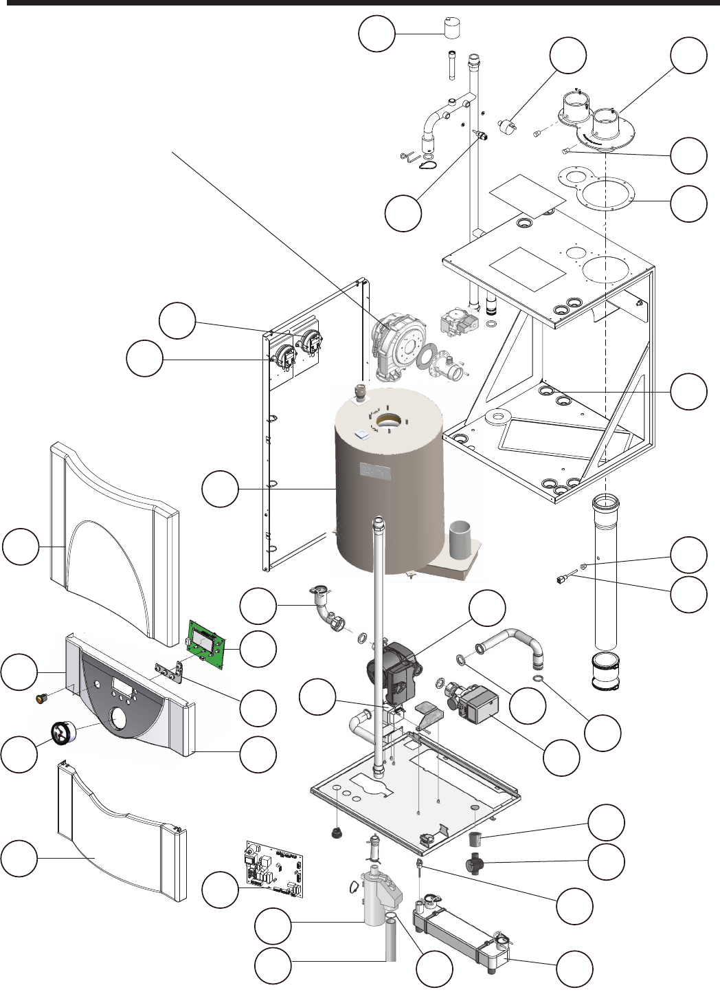
Page 48
BRADFORD WHITE CORP
.
SECTION 13.
Replacement Parts
13.1 Exploded Parts Views, and
their Bradford White Part
Numbers
12
11 42
43
44
45
13
10
14
26
40
7
38
3935
37
41
6
3
1 2 27
30
5
4
32
28
31
29
33
34
4
See Figure 31
and Figure 32,
for blower and
combustion parts
Figure 30. Parts
46
47
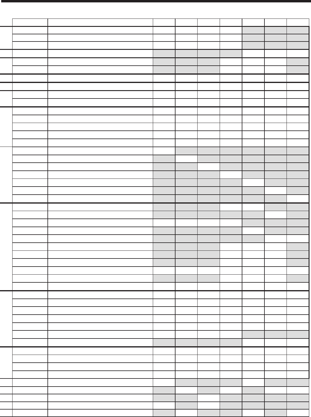
Page 49
Brute LX
2-Jun-14
Ref Laars PN Description 50 75 100 125 150 175 220
12P9102 1P2067603 PIPE, PVC, 3/4" SCH 40 X 6" LONG xxxx
2S2116300 O-RING, -120, 1" ID X 1-3/16" OD xxxx
3A2117500 TRAP, CONDENSATE xxxx
3R2076000 TRAP KIT, CONDENSATE - LARGE xxx
12P9103 4P2093100 COUPLING, PIPE, SS, 1/2" NPT xxx
5E2359000 FLOW SENSOR - DHW xxx
RE2356900 6RE2356900 CONTROL BOARD - w/Firmware xxxxxxx
7E2356800 DISPLAY UNIT xxxxxxx
12P7008 8E2335100 CIRCUIT BREAKER, 2A xxxxxxx
9E2318900 CIRCUIT BREAKER, 10 AMP xxxxxxx
12P3002 10 E2357200 SENSOR, DUPLEX, FLUE xxxxxxx
11 P2074600 SWITCH, LOW PRESSURE xxxxxxx
12 P2074500 VENT, AIR, AUTO xxxxxxx
13 E2357300 GROMMET, SENSOR, FLUE xxxxxxx
14 E2357500 SENSOR, OUTLET xxxxxxx
12P2003 15 S2105400 GASKET, BLOWER/ FAN OUTLET xxxxxxx
16 12P2065 ADAPTER PLATE xxxxxxx
17 S2124500 ORING, BLOWER INLET xxxx
18 S2127600 GASKET, VENTURI TO BLOWER xxx
19 RA2112400 BLOWER, COMBUSTION 50 - 75 x x
19 A2122500 BLOWER, COMBUSTION 100-125 x x
19 RA2114200 BLOWER, COMBUSTION 150-220 xxx
20 V2022700 VALVE, GAS, LHX xxxxxxx
12p2000 21 RW2013400 GASKET, FLAME SENSOR xxxxxxx
22 W2014200 IGNITOR, SPARK xxxxxxx
23 W2014300 SENSOR, FLAME xxxxxxx
24 RL2018401 BURNER 50-75 x x
24 RL2018402 BURNER 100 x
24 RL2018403 BURNER 125-175 xxx
24 RL2018404 BURNER 220 x
25 S2127300 GASKET, BURNER, ABOVE FLANGE xxxxxxx
26 S2127200 GASKET, BURNER, BELOW FLANGE xxxxxxx
27 RW2013300 GASKET, IGNITOR xxxxxxx
26 05P2100 HEAT EXCHANGER 50 x
26 07P2100 HEAT EXCHANGER 75 x
26 10P2100 HEAT EXCHANGER 100 x
26 12P2100 HEAT EXCHANGER 125 x
26 15P2100 HEAT EXCHANGER 150 x
26 17P2100 HEAT EXCHANGER 175 x
26 22P2100 HEAT EXCHANGER 220 x
12P4000 27 S2123800 HEAT EXCHANGER PLATE 125/150 x x
27 S2125400 HEAT EXCHANGER PLATE 175 x
28 A2117700 PUMP 50-125 xxxx
28 Call Factory PUMP 150 x
28 A2122600 PUMP 175-220 x x
29 A2122004 3-WAY VALVE, ACTUATOR xxx
30 RE2337501 SENSOR, TEMPERATURE, DHW xxx
31 F2027600 WASHER, SEALING, 1.19 OD X .79 ID xxx
32 R0021300 TRANSFORMER,40VA, 115V/24V xxxxxxx
33 S2115100 O RING, 20.04 mm I.D. X 27.10 mm O.D. xxx
34 E2357000 SENSOR, TEMPERATURE, INLET xxxxxxx
12P3003 35 A2117600 GAUGE, PRESS/TEMP xxxx x x x
37 E2335000 SWITCH, ROCKER, 120V, AMBER xxxxxxx
38 E2357700 COVER, DISPLAY, PUSH BUTTON xxxxxxx
39 12P7015 PANEL, MIDDLE xxxxxxx
40 12P3006 PANEL, TOP LAARS W/TREELOK xxxxxxx
41 12P3004 PANEL, BOTTOM SHORT xxxx
41 12P3005 PANEL, BOTTOM LONG xxx
12P3001 42 12H5500 ADAPTER, VENT, CPVC xxxxxxx
43 500-168 PLUG, HEX, 1/8" NPT xxxxxxx
44 12H5501 GASKET, VENT ADAPTER, M2 125 xxxxxxx
45 S2114000 GROMMET xxxxxxx
46 E2334702 SWITCH, PRESSURE, FAN PROVING x x
46 E2334700 SWITCH, PRESSURE, FAN PROVING x x x x
46 E2334701 SWITCH, PRESSURE, FAN PROVING x
47 E2344901 SWITCH, PRESSURE, VENT PRESSURE x x
47
E2312401
SWITCH, PRESSURE, VENT PRESSURE x x x
Part #
W/TREELOCK
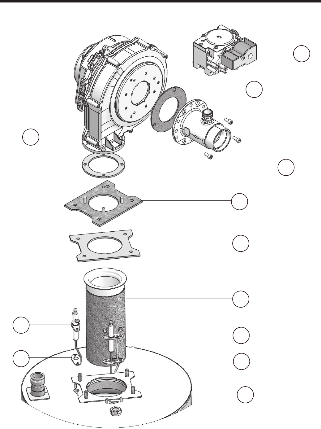
Page 50
BRADFORD WHITE CORP
.
4
Figure 31. Parts, Blowers and Combustion
20
18
15
16
26
24
25
27
22
23
21
19
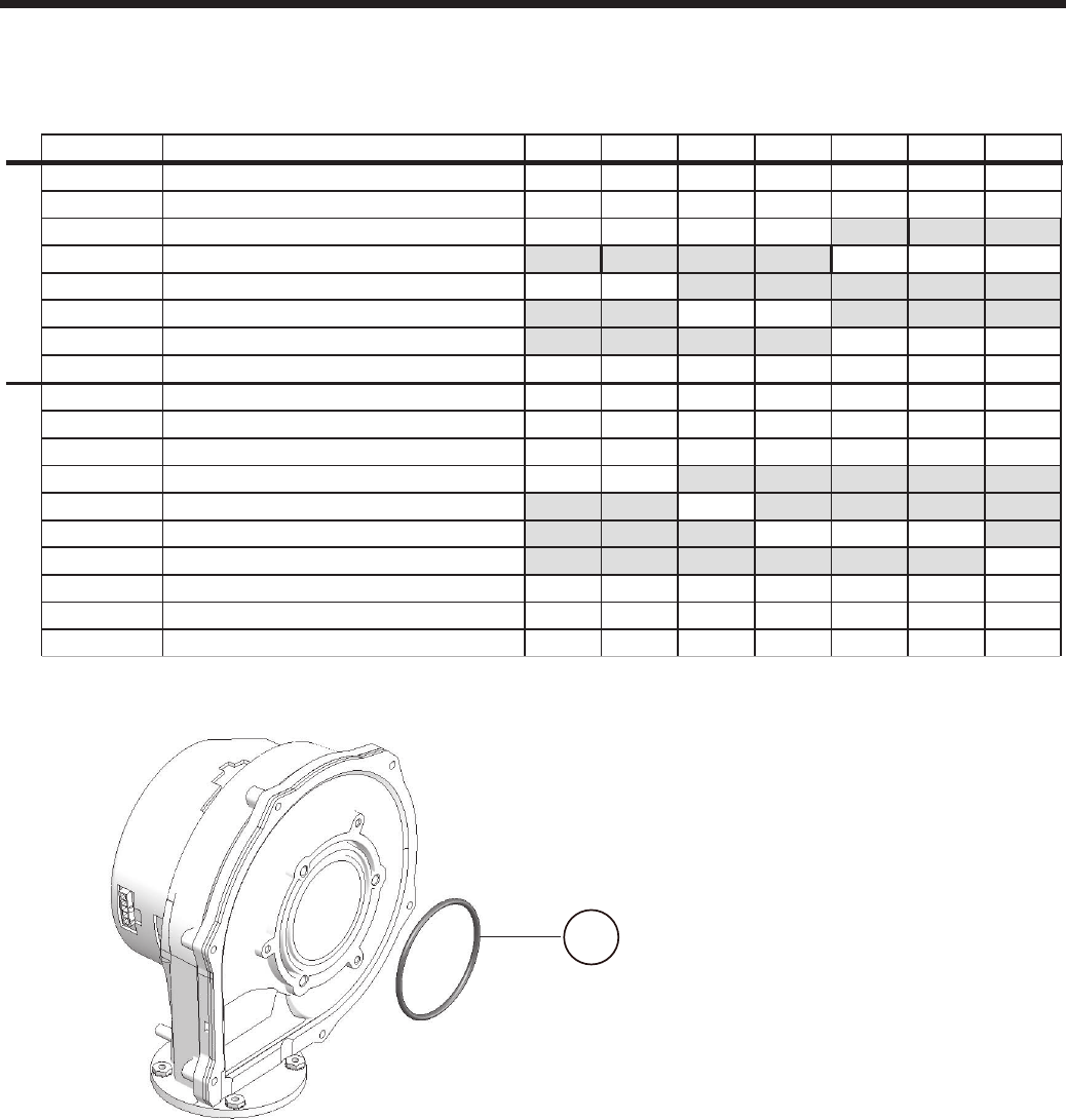
Page 51
Brute LX
2-Jun-14
Ref Laars PN Description 50 75 100 125 150 175 220
12P9102 1P2067603 PIPE, PVC, 3/4" SCH 40 X 6" LONG xxxx
2S2116300 O-RING, -120, 1" ID X 1-3/16" OD xxxx
3A2117500 TRAP, CONDENSATE xxxx
3R2076000 TRAP KIT, CONDENSATE - LARGE xxx
12P9103 4P2093100 COUPLING, PIPE, SS, 1/2" NPT xxx
5E2359000 FLOW SENSOR - DHW xxx
RE2356900 6RE2356900 CONTROL BOARD - w/Firmware xxxxxxx
7E2356800 DISPLAY UNIT xxxxxxx
12P7008 8E2335100 CIRCUIT BREAKER, 2A xxxxxxx
9E2318900 CIRCUIT BREAKER, 10 AMP xxxxxxx
12P3002 10 E2357200 SENSOR, DUPLEX, FLUE xxxxxxx
11 P2074600 SWITCH, LOW PRESSURE xxxxxxx
12 P2074500 VENT, AIR, AUTO xxxxxxx
13 E2357300 GROMMET, SENSOR, FLUE xxxxxxx
14 E2357500 SENSOR, OUTLET xxxxxxx
12P2003 15 S2105400 GASKET, BLOWER/ FAN OUTLET xxxxxxx
16 12P2065 ADAPTER PLATE xxxxxxx
17 S2124500 ORING, BLOWER INLET xxxx
18 S2127600 GASKET, VENTURI TO BLOWER xxx
19 RA2112400 BLOWER, COMBUSTION 50 - 75 x x
19 A2122500 BLOWER, COMBUSTION 100-125 x x
19 RA2114200 BLOWER, COMBUSTION 150-220 xxx
20 V2022700 VALVE, GAS, LHX xxxxxxx
12p2000 21 RW2013400 GASKET, FLAME SENSOR xxxxxxx
22 W2014200 IGNITOR, SPARK xxxxxxx
23 W2014300 SENSOR, FLAME xxxxxxx
24 RL2018401 BURNER 50-75 x x
24 RL2018402 BURNER 100 x
24 RL2018403 BURNER 125-175 xxx
24 RL2018404 BURNER 220 x
25 S2127300 GASKET, BURNER, ABOVE FLANGE xxxxxxx
26 S2127200 GASKET, BURNER, BELOW FLANGE xxxxxxx
27 RW2013300 GASKET, IGNITOR xxxxxxx
26 05P2100 HEAT EXCHANGER 50 x
26 07P2100 HEAT EXCHANGER 75 x
26 10P2100 HEAT EXCHANGER 100 x
26 12P2100 HEAT EXCHANGER 125 x
26 15P2100 HEAT EXCHANGER 150 x
26 17P2100 HEAT EXCHANGER 175 x
26 22P2100 HEAT EXCHANGER 220 x
12P4000 27 S2123800 HEAT EXCHANGER PLATE 125/150 x x
27 S2125400 HEAT EXCHANGER PLATE 175 x
28 A2117700 PUMP 50-125 xxxx
28 Call Factory PUMP 150 x
28 A2122600 PUMP 175-220 x x
29 A2122004 3-WAY VALVE, ACTUATOR xxx
30 RE2337501 SENSOR, TEMPERATURE, DHW xxx
31 F2027600 WASHER, SEALING, 1.19 OD X .79 ID xxx
32 R0021300 TRANSFORMER,40VA, 115V/24V xxxxxxx
33 S2115100 O RING, 20.04 mm I.D. X 27.10 mm O.D. xxx
34 E2357000 SENSOR, TEMPERATURE, INLET xxxxxxx
12P3003 35 A2117600 GAUGE, PRESS/TEMP xxxx x x x
37 E2335000 SWITCH, ROCKER, 120V, AMBER xxxxxxx
38 E2357700 COVER, DISPLAY, PUSH BUTTON xxxxxxx
39 12P7015 PANEL, MIDDLE xxxxxxx
40 12P3006 PANEL, TOP LAARS W/TREELOK xxxxxxx
41 12P3004 PANEL, BOTTOM SHORT xxxx
41 12P3005 PANEL, BOTTOM LONG xxx
12P3001 42 12H5500 ADAPTER, VENT, CPVC xxxxxxx
43 500-168 PLUG, HEX, 1/8" NPT xxxxxxx
44 12H5501 GASKET, VENT ADAPTER, M2 125 xxxxxxx
45 S2114000 GROMMET xxxxxxx
46 E2334702 SWITCH, PRESSURE, FAN PROVING x x
46 E2334700 SWITCH, PRESSURE, FAN PROVING x x x x
46 E2334701 SWITCH, PRESSURE, FAN PROVING x
47 E2344901 SWITCH, PRESSURE, VENT PRESSURE x x
47 E2312401 SWITCH, PRESSURE, VENT PRESSURE x x x
2-Jun-14
Ref Laars PN Description 50 75 100 125 150 175 220
12P9102 1P2067603 PIPE, PVC, 3/4" SCH 40 X 6" LONG xxxx
2S2116300 O-RING, -120, 1" ID X 1-3/16" OD xxxx
3A2117500 TRAP, CONDENSATE xxxx
3R2076000 TRAP KIT, CONDENSATE - LARGE xxx
12P9103 4P2093100 COUPLING, PIPE, SS, 1/2" NPT xxx
5E2359000 FLOW SENSOR - DHW xxx
RE2356900 6RE2356900 CONTROL BOARD - w/Firmware xxxxxxx
7E2356800 DISPLAY UNIT xxxxxxx
12P7008 8E2335100 CIRCUIT BREAKER, 2A xxxxxxx
9E2318900 CIRCUIT BREAKER, 10 AMP xxxxxxx
12P3002 10 E2357200 SENSOR, DUPLEX, FLUE xxxxxxx
11 P2074600 SWITCH, LOW PRESSURE xxxxxxx
12 P2074500 VENT, AIR, AUTO xxxxxxx
13 E2357300 GROMMET, SENSOR, FLUE xxxxxxx
14 E2357500 SENSOR, OUTLET xxxxxxx
12P2003 15 S2105400 GASKET, BLOWER/ FAN OUTLET xxxxxxx
16 12P2065 ADAPTER PLATE xxxxxxx
17 S2124500 ORING, BLOWER INLET xxxx
18 S2127600 GASKET, VENTURI TO BLOWER xxx
19 RA2112400 BLOWER, COMBUSTION 50 - 75 x x
19 A2122500 BLOWER, COMBUSTION 100-125 x x
19 RA2114200 BLOWER, COMBUSTION 150-220 xxx
20 V2022700 VALVE, GAS, LHX xxxxxxx
12p2000 21 RW2013400 GASKET, FLAME SENSOR xxxxxxx
22 W2014200 IGNITOR, SPARK xxxxxxx
23 W2014300 SENSOR, FLAME xxxxxxx
24 RL2018401 BURNER 50-75 x x
24 RL2018402 BURNER 100 x
24 RL2018403 BURNER 125-175 xxx
24 RL2018404 BURNER 220 x
25 S2127300 GASKET, BURNER, ABOVE FLANGE xxxxxxx
26 S2127200 GASKET, BURNER, BELOW FLANGE xxxxxxx
27 RW2013300 GASKET, IGNITOR xxxxxxx
26 05P2100 HEAT EXCHANGER 50 x
26 07P2100 HEAT EXCHANGER 75 x
26 10P2100 HEAT EXCHANGER 100 x
26 12P2100 HEAT EXCHANGER 125 x
26 15P2100 HEAT EXCHANGER 150 x
26 17P2100 HEAT EXCHANGER 175 x
26 22P2100 HEAT EXCHANGER 220 x
12P4000 27 S2123800 HEAT EXCHANGER PLATE 125/150 x x
27 S2125400 HEAT EXCHANGER PLATE 175 x
28 A2117700 PUMP 50-125 xxxx
28 Call Factory PUMP 150 x
28 A2122600 PUMP 175-220 x x
29 A2122004 3-WAY VALVE, ACTUATOR xxx
30 RE2337501 SENSOR, TEMPERATURE, DHW xxx
31 F2027600 WASHER, SEALING, 1.19 OD X .79 ID xxx
32 R0021300 TRANSFORMER,40VA, 115V/24V xxxxxxx
33 S2115100 O RING, 20.04 mm I.D. X 27.10 mm O.D. xxx
34 E2357000 SENSOR, TEMPERATURE, INLET xxxxxxx
12P3003 35 A2117600 GAUGE, PRESS/TEMP xxxx x x x
37 E2335000 SWITCH, ROCKER, 120V, AMBER xxxxxxx
38 E2357700 COVER, DISPLAY, PUSH BUTTON xxxxxxx
39 12P7015 PANEL, MIDDLE xxxxxxx
40 12P3006 PANEL, TOP LAARS W/TREELOK xxxxxxx
41 12P3004 PANEL, BOTTOM SHORT xxxx
41 12P3005 PANEL, BOTTOM LONG xxx
12P3001 42 12H5500 ADAPTER, VENT, CPVC xxxxxxx
43 500-168 PLUG, HEX, 1/8" NPT xxxxxxx
44 12H5501 GASKET, VENT ADAPTER, M2 125 xxxxxxx
45 S2114000 GROMMET xxxxxxx
46 E2334702 SWITCH, PRESSURE, FAN PROVING x x
46 E2334700 SWITCH, PRESSURE, FAN PROVING x x x x
46 E2334701 SWITCH, PRESSURE, FAN PROVING x
47 E2344901 SWITCH, PRESSURE, VENT PRESSURE x x
47
E2312401
SWITCH, PRESSURE, VENT PRESSURE x x x
Figure 32. Blower for models 50, 75, 100, and 125
Part #
17

BRADFORD WHITE CORP
.
H2364001A
Dimensions and specications subject to change without notice in accordance with our policy of continuous product improvement.
200 Lafayette St.
Middleville, MI 49333
Warranty: (800) 531-2111
www.BradfordWhite.com
Litho in U.S.A. © Bradford White 1410 Document 1295A-BW
