Brady 76800 GM MB II User Manual To The 43f11f92 0810 40e4 B98f 86b9025c13b2
User Manual: Brady 76800 to the manual
Open the PDF directly: View PDF ![]() .
.
Page Count: 267 [warning: Documents this large are best viewed by clicking the View PDF Link!]
- Copyright
- Disclaimer
- End User License Agreement for Microsoft Windows CE„
- Brady Warranty
- FCC Notice-US Only
- Specifications
- International Power Cords
- CHAPTER 1 Welcome
- CHAPTER 2 Setting Up
- CHAPTER 3 Starting Up
- CHAPTER 4 Basic Procedures
- CHAPTER 5 Setting Preferences
- CHAPTER 6 Working with Labels
- Creating Custom Labels
- Creating QuickText Labels
- Creating Template Labels
- Creating Sets of Labels
- Changing Labels
- Setting Application Preferences
- CHAPTER 7 Working with Objects
- About Objects
- Adding Objects
- Selecting Objects
- Moving Objects
- Sizing Objects
- Copying and Pasting Objects
- Changing Objects
- Opening and editing an object
- Changing object properties
- CHAPTER 8 Applying Color
- CHAPTER 9 Working with Files
- CHAPTER 10 Working with Cut-outs
- CHAPTER 11 Printing
- CHAPTER 12 Connecting to a PC
- Appendix A Special Characters
- Appendix B Cutter Maintenance
- Appendix C Error Messages

1
Copyright - - - - - - - - - - - - - - - - - - - - - - - - - - - - - - - - - - - - - - - - - - - - - - - - - - - i-iii
Disclaimer- - - - - - - - - - - - - - - - - - - - - - - - - - - - - - - - - - - - - - - - - - - - - - - - - - - i-iii
End User License Agreement for Microsoft Windows CE„ - - - - - - - - - - - - - - - - - - i-iv
Brady Warranty - - - - - - - - - - - - - - - - - - - - - - - - - - - - - - - - - - - - - - - - - - - - - - - i-v
FCC Notice-US Only - - - - - - - - - - - - - - - - - - - - - - - - - - - - - - - - - - - - - - - - - - - i-vi
Canada - - - - - - - - - - - - - - - - - - - - - - - - - - - - - - - - - - - - - - - - - - - - - - - - - - - - - - - i-vi
Europe - - - - - - - - - - - - - - - - - - - - - - - - - - - - - - - - - - - - - - - - - - - - - - - - - - - - - - - - i-vi
Specifications - - - - - - - - - - - - - - - - - - - - - - - - - - - - - - - - - - - - - - - - - - - - - - - - i-vii
Physical characteristics - - - - - - - - - - - - - - - - - - - - - - - - - - - - - - - - - - - - - - - - - - - - i-vii
Environmental characteristics - - - - - - - - - - - - - - - - - - - - - - - - - - - - - - - - - - - - - - - - i-vii
Electrical characteristics - - - - - - - - - - - - - - - - - - - - - - - - - - - - - - - - - - - - - - - - - - - i-vii
International Power Cords - - - - - - - - - - - - - - - - - - - - - - - - - - - - - - - - - - - - - - - - i-viii
CHAPTER 1 Welcome
About This Book - - - - - - - - - - - - - - - - - - - - - - - - - - - - - - - - - - - - - - - - - - - - - - 1-2
Features and Functions - - - - - - - - - - - - - - - - - - - - - - - - - - - - - - - - - - - - - - - - - - 1-2
The three printer systems- - - - - - - - - - - - - - - - - - - - - - - - - - - - - - - - - - - - - - - - - - - - 1-3
Specialty applications- - - - - - - - - - - - - - - - - - - - - - - - - - - - - - - - - - - - - - - - - - - - - - 1-4
Contacting Technical Support- - - - - - - - - - - - - - - - - - - - - - - - - - - - - - - - - - - - - - 1-5
Americas - - - - - - - - - - - - - - - - - - - - - - - - - - - - - - - - - - - - - - - - - - - - - - - - - - - - - - 1-5
Europe - - - - - - - - - - - - - - - - - - - - - - - - - - - - - - - - - - - - - - - - - - - - - - - - - - - - - - - - 1-5
Pacific - - - - - - - - - - - - - - - - - - - - - - - - - - - - - - - - - - - - - - - - - - - - - - - - - - - - - - - - 1-6
CHAPTER 2 Setting Up
Connecting Peripherals - - - - - - - - - - - - - - - - - - - - - - - - - - - - - - - - - - - - - - - - - - 2-2
Installing supplies- - - - - - - - - - - - - - - - - - - - - - - - - - - - - - - - - - - - - - - - - - - - - - 2-3
Opening the printer - - - - - - - - - - - - - - - - - - - - - - - - - - - - - - - - - - - - - - - - - - - - - - - 2-4
Installing a ribbon cartridge - - - - - - - - - - - - - - - - - - - - - - - - - - - - - - - - - - - - - - - - - 2-5
Adjusting the ribbon cartridge - - - - - - - - - - - - - - - - - - - - - - - - - - - - - - - - - - - - - - - - 2-6
Installing a tape cartridge - - - - - - - - - - - - - - - - - - - - - - - - - - - - - - - - - - - - - - - - - - - 2-7
Closing the printer cover- - - - - - - - - - - - - - - - - - - - - - - - - - - - - - - - - - - - - - - - - - - - 2-11
Installing a compact flash memory card - - - - - - - - - - - - - - - - - - - - - - - - - - - - - - - 2-13
Cleaning your system - - - - - - - - - - - - - - - - - - - - - - - - - - - - - - - - - - - - - - - - - - - 2-14
CHAPTER 3 Starting Up
Launching Your System - - - - - - - - - - - - - - - - - - - - - - - - - - - - - - - - - - - - - - - - - 3-2
The Main Menu - - - - - - - - - - - - - - - - - - - - - - - - - - - - - - - - - - - - - - - - - - - - - - - - - - 3-2
Keyboard Basics - - - - - - - - - - - - - - - - - - - - - - - - - - - - - - - - - - - - - - - - - - - - - - 3-4

2
The standard keyboard - - - - - - - - - - - - - - - - - - - - - - - - - - - - - - - - - - - - - - - - - - - - - - 3-5
System function keys - - - - - - - - - - - - - - - - - - - - - - - - - - - - - - - - - - - - - - - - - - - - - - - 3-5
Alphabetic and command keys- - - - - - - - - - - - - - - - - - - - - - - - - - - - - - - - - - - - - - - - - 3-9
Arrow and navigation keypads- - - - - - - - - - - - - - - - - - - - - - - - - - - - - - - - - - - - - - - - - 3-11
Numeric keypad - - - - - - - - - - - - - - - - - - - - - - - - - - - - - - - - - - - - - - - - - - - - - - - - - - 3-14
Shortcut keys - - - - - - - - - - - - - - - - - - - - - - - - - - - - - - - - - - - - - - - - - - - - - - - - - - - - 3-16
Mouse Basics - - - - - - - - - - - - - - - - - - - - - - - - - - - - - - - - - - - - - - - - - - - - - - - - -3-16
Using a mouse on labels - - - - - - - - - - - - - - - - - - - - - - - - - - - - - - - - - - - - - - - - - - - - - 3-17
Checking System Status - - - - - - - - - - - - - - - - - - - - - - - - - - - - - - - - - - - - - - - - - -3-17
Accessing Online Help- - - - - - - - - - - - - - - - - - - - - - - - - - - - - - - - - - - - - - - - - - -3-18
CHAPTER 4 Basic Procedures
Working in the Editor window- - - - - - - - - - - - - - - - - - - - - - - - - - - - - - - - - - - - - -4-2
Inside the Editor window - - - - - - - - - - - - - - - - - - - - - - - - - - - - - - - - - - - - - - - - - - - - 4-3
Editing procedures- - - - - - - - - - - - - - - - - - - - - - - - - - - - - - - - - - - - - - - - - - - - - - - - - 4-7
Working in Entry Screens - - - - - - - - - - - - - - - - - - - - - - - - - - - - - - - - - - - - - - - - -4-9
Navigating in entry screens- - - - - - - - - - - - - - - - - - - - - - - - - - - - - - - - - - - - - - - - - - -4-9
Entering information in entry screens - - - - - - - - - - - - - - - - - - - - - - - - - - - - - - - - - - - - 4-11
Choosing options- - - - - - - - - - - - - - - - - - - - - - - - - - - - - - - - - - - - - - - - - - - - - - - - - - 4-12
Exiting entry screens - - - - - - - - - - - - - - - - - - - - - - - - - - - - - - - - - - - - - - - - - - - - - - -4-15
CHAPTER 5 Setting Preferences
Accessing System Setup - - - - - - - - - - - - - - - - - - - - - - - - - - - - - - - - - - - - - - - - - -5-2
Setting Printing Tab Options - - - - - - - - - - - - - - - - - - - - - - - - - - - - - - - - - - - - - - -5-4
Setting Localization Tab Options - - - - - - - - - - - - - - - - - - - - - - - - - - - - - - - - - - - -5-6
Setting Hardware Tab Options- - - - - - - - - - - - - - - - - - - - - - - - - - - - - - - - - - - - - -5-8
Naming supply colors- - - - - - - - - - - - - - - - - - - - - - - - - - - - - - - - - - - - - - - - - - - - - - - 5-9
Setting Other Tab Options- - - - - - - - - - - - - - - - - - - - - - - - - - - - - - - - - - - - - - - - -5-10
Displaying the screen grid - - - - - - - - - - - - - - - - - - - - - - - - - - - - - - - - - - - - - - - - - - - 5-11
Setting Text Tab Options - - - - - - - - - - - - - - - - - - - - - - - - - - - - - - - - - - - - - - - - -5-12
Setting On Line Tab Options - - - - - - - - - - - - - - - - - - - - - - - - - - - - - - - - - - - - - - -5-15
CHAPTER 6 Working with Labels
Creating Custom Labels - - - - - - - - - - - - - - - - - - - - - - - - - - - - - - - - - - - - - - - - - -6-2
Creating QuickText Labels - - - - - - - - - - - - - - - - - - - - - - - - - - - - - - - - - - - - - - - -6-5
QuickText toolbar functions - - - - - - - - - - - - - - - - - - - - - - - - - - - - - - - - - - - - - - - - - - 6-7
QuickText key functions - - - - - - - - - - - - - - - - - - - - - - - - - - - - - - - - - - - - - - - - - - - - - 6-9
Creating Template Labels - - - - - - - - - - - - - - - - - - - - - - - - - - - - - - - - - - - - - - - - -6-10

3
Pipe Marker and Right-to-Know exceptions - - - - - - - - - - - - - - - - - - - - - - - - - - - - - - - 6-11
Choosing a label application - - - - - - - - - - - - - - - - - - - - - - - - - - - - - - - - - - - - - - - - - 6-11
Choosing a category- - - - - - - - - - - - - - - - - - - - - - - - - - - - - - - - - - - - - - - - - - - - - - - 6-12
Selecting a template - - - - - - - - - - - - - - - - - - - - - - - - - - - - - - - - - - - - - - - - - - - - - - - 6-13
Following prompt sequences - - - - - - - - - - - - - - - - - - - - - - - - - - - - - - - - - - - - - - - - - 6-16
Creating Sets of Labels - - - - - - - - - - - - - - - - - - - - - - - - - - - - - - - - - - - - - - - - - - 6-21
Adding labels to a label set - - - - - - - - - - - - - - - - - - - - - - - - - - - - - - - - - - - - - - - - - - 6-22
Moving between labels in a label set - - - - - - - - - - - - - - - - - - - - - - - - - - - - - - - - - - - - 6-23
Editing labels in a label set - - - - - - - - - - - - - - - - - - - - - - - - - - - - - - - - - - - - - - - - - - 6-23
Clearing labels in a label set - - - - - - - - - - - - - - - - - - - - - - - - - - - - - - - - - - - - - - - - - 6-23
Saving label sets - - - - - - - - - - - - - - - - - - - - - - - - - - - - - - - - - - - - - - - - - - - - - - - - - 6-24
Changing Labels - - - - - - - - - - - - - - - - - - - - - - - - - - - - - - - - - - - - - - - - - - - - - - 6-24
Changing the size of template labels - - - - - - - - - - - - - - - - - - - - - - - - - - - - - - - - - - - - 6-25
Editing template labels - - - - - - - - - - - - - - - - - - - - - - - - - - - - - - - - - - - - - - - - - - - - - 6-26
Changing Label Properties - - - - - - - - - - - - - - - - - - - - - - - - - - - - - - - - - - - - - - - - - - 6-27
Setting Application Preferences - - - - - - - - - - - - - - - - - - - - - - - - - - - - - - - - - - - - 6-33
CHAPTER 7 Working with Objects
About Objects - - - - - - - - - - - - - - - - - - - - - - - - - - - - - - - - - - - - - - - - - - - - - - - - 7-2
Adding Objects - - - - - - - - - - - - - - - - - - - - - - - - - - - - - - - - - - - - - - - - - - - - - - - 7-3
Adding and formatting text objects - - - - - - - - - - - - - - - - - - - - - - - - - - - - - - - - - - - - - 7-4
Adding variable text objects- - - - - - - - - - - - - - - - - - - - - - - - - - - - - - - - - - - - - - - - - - 7-10
Adding vertical text objects - - - - - - - - - - - - - - - - - - - - - - - - - - - - - - - - - - - - - - - - - - 7-16
Adding bar code objects - - - - - - - - - - - - - - - - - - - - - - - - - - - - - - - - - - - - - - - - - - - - 7-17
Adding graphics objects - - - - - - - - - - - - - - - - - - - - - - - - - - - - - - - - - - - - - - - - - - - - 7-22
Adding HotShapes - - - - - - - - - - - - - - - - - - - - - - - - - - - - - - - - - - - - - - - - - - - - - - - - 7-24
Selecting Objects - - - - - - - - - - - - - - - - - - - - - - - - - - - - - - - - - - - - - - - - - - - - - - 7-25
Selecting a layered object - - - - - - - - - - - - - - - - - - - - - - - - - - - - - - - - - - - - - - - - - - - 7-26
Moving Objects - - - - - - - - - - - - - - - - - - - - - - - - - - - - - - - - - - - - - - - - - - - - - - - 7-26
Sizing Objects - - - - - - - - - - - - - - - - - - - - - - - - - - - - - - - - - - - - - - - - - - - - - - - - 7-27
Using Increase Size and Decrease Size - - - - - - - - - - - - - - - - - - - - - - - - - - - - - - - - - - 7-28
Using the Scale function - - - - - - - - - - - - - - - - - - - - - - - - - - - - - - - - - - - - - - - - - - - - 7-28
Copying and Pasting Objects - - - - - - - - - - - - - - - - - - - - - - - - - - - - - - - - - - - - - - 7-30
Changing Objects - - - - - - - - - - - - - - - - - - - - - - - - - - - - - - - - - - - - - - - - - - - - - - 7-31
Opening and editing an object - - - - - - - - - - - - - - - - - - - - - - - - - - - - - - - - - - - - - - - - 7-31
Changing object properties - - - - - - - - - - - - - - - - - - - - - - - - - - - - - - - - - - - - - - - - - - 7-32
CHAPTER 8 Applying Color
About Color - - - - - - - - - - - - - - - - - - - - - - - - - - - - - - - - - - - - - - - - - - - - - - - - - 8-2

4
Ribbon color- - - - - - - - - - - - - - - - - - - - - - - - - - - - - - - - - - - - - - - - - - - - - - - - - - - - - 8-2
Tape color - - - - - - - - - - - - - - - - - - - - - - - - - - - - - - - - - - - - - - - - - - - - - - - - - - - - - - 8-4
Applying Color to Objects - - - - - - - - - - - - - - - - - - - - - - - - - - - - - - - - - - - - - - - -8-5
About the Object Color screen- - - - - - - - - - - - - - - - - - - - - - - - - - - - - - - - - - - - - - - - - 8-5
Choosing color on the Monocolor system - - - - - - - - - - - - - - - - - - - - - - - - - - - - - - - - - 8-6
Choosing color on the Multicolor and Color & Cut systems - - - - - - - - - - - - - - - - - - - - -8-7
Printing Color - - - - - - - - - - - - - - - - - - - - - - - - - - - - - - - - - - - - - - - - - - - - - - - - -8-9
CHAPTER 9 Working with Files
About Files and File Groups - - - - - - - - - - - - - - - - - - - - - - - - - - - - - - - - - - - - - - -9-2
Saving Labels as Files - - - - - - - - - - - - - - - - - - - - - - - - - - - - - - - - - - - - - - - - - - -9-3
Managing Files - - - - - - - - - - - - - - - - - - - - - - - - - - - - - - - - - - - - - - - - - - - - - - - -9-7
Opening saved label files - - - - - - - - - - - - - - - - - - - - - - - - - - - - - - - - - - - - - - - - - - - - 9-7
Editing files - - - - - - - - - - - - - - - - - - - - - - - - - - - - - - - - - - - - - - - - - - - - - - - - - - - - - 9-10
Deleting files - - - - - - - - - - - - - - - - - - - - - - - - - - - - - - - - - - - - - - - - - - - - - - - - - - - - 9-11
Printing Files - - - - - - - - - - - - - - - - - - - - - - - - - - - - - - - - - - - - - - - - - - - - - - - - -9-12
Transferring Files - - - - - - - - - - - - - - - - - - - - - - - - - - - - - - - - - - - - - - - - - - - - - -9-12
Using My Templates - - - - - - - - - - - - - - - - - - - - - - - - - - - - - - - - - - - - - - - - - - - -9-12
Accessing template files - - - - - - - - - - - - - - - - - - - - - - - - - - - - - - - - - - - - - - - - - - - - - 9-13
Changing My Template label size- - - - - - - - - - - - - - - - - - - - - - - - - - - - - - - - - - - - - - - 9-14
CHAPTER 10 Working with Cut-outs
About Cutting - - - - - - - - - - - - - - - - - - - - - - - - - - - - - - - - - - - - - - - - - - - - - - - - -10-2
Creating Cut Out Objects - - - - - - - - - - - - - - - - - - - - - - - - - - - - - - - - - - - - - - - - -10-3
Adding cut out objects - - - - - - - - - - - - - - - - - - - - - - - - - - - - - - - - - - - - - - - - - - - - - -10-4
Cutting Around Objects - - - - - - - - - - - - - - - - - - - - - - - - - - - - - - - - - - - - - - - - - -10-8
Minimum cut size - - - - - - - - - - - - - - - - - - - - - - - - - - - - - - - - - - - - - - - - - - - - - - - - - 10-9
Cutting Around Label Frames - - - - - - - - - - - - - - - - - - - - - - - - - - - - - - - - - - - - - -10-10
Calibrating the Cutter- - - - - - - - - - - - - - - - - - - - - - - - - - - - - - - - - - - - - - - - - - - -10-11
Setting cutter calibration values- - - - - - - - - - - - - - - - - - - - - - - - - - - - - - - - - - - - - - - - 10-11
Restoring default cutter calibration settings- - - - - - - - - - - - - - - - - - - - - - - - - - - - - - - - 10-14
CHAPTER 11 Printing
Printing Labels - - - - - - - - - - - - - - - - - - - - - - - - - - - - - - - - - - - - - - - - - - - - - - - -11-2
About pages - - - - - - - - - - - - - - - - - - - - - - - - - - - - - - - - - - - - - - - - - - - - - - - - - - - - - 11-2
Printing a single label - - - - - - - - - - - - - - - - - - - - - - - - - - - - - - - - - - - - - - - - - - - - - -11-4
Printing multiple copies of a single label- - - - - - - - - - - - - - - - - - - - - - - - - - - - - - - - - - 11-5
Printing labels in a label set - - - - - - - - - - - - - - - - - - - - - - - - - - - - - - - - - - - - - - - - - -11-6

5
Printing labels in a file group- - - - - - - - - - - - - - - - - - - - - - - - - - - - - - - - - - - - - - - - - 11-7
Checking Supplies - - - - - - - - - - - - - - - - - - - - - - - - - - - - - - - - - - - - - - - - - - - - - 11-10
Checking Size - - - - - - - - - - - - - - - - - - - - - - - - - - - - - - - - - - - - - - - - - - - - - - - - 11-11
Checking Length - - - - - - - - - - - - - - - - - - - - - - - - - - - - - - - - - - - - - - - - - - - - - - 11-12
Minimum length- - - - - - - - - - - - - - - - - - - - - - - - - - - - - - - - - - - - - - - - - - - - - - - - - - 11-12
Maximum length - - - - - - - - - - - - - - - - - - - - - - - - - - - - - - - - - - - - - - - - - - - - - - - - - 11-12
Cut out label length - - - - - - - - - - - - - - - - - - - - - - - - - - - - - - - - - - - - - - - - - - - - - - - 11-15
Checking Color - - - - - - - - - - - - - - - - - - - - - - - - - - - - - - - - - - - - - - - - - - - - - - - 11-15
Ribbon and color choices - - - - - - - - - - - - - - - - - - - - - - - - - - - - - - - - - - - - - - - - - - - 11-15
Ribbon color needed- - - - - - - - - - - - - - - - - - - - - - - - - - - - - - - - - - - - - - - - - - - - - - - 11-17
Tape color needed - - - - - - - - - - - - - - - - - - - - - - - - - - - - - - - - - - - - - - - - - - - - - - - - 11-18
Checking for cut out labels - - - - - - - - - - - - - - - - - - - - - - - - - - - - - - - - - - - - - - - - - - 11-19
Printing Tab Options - - - - - - - - - - - - - - - - - - - - - - - - - - - - - - - - - - - - - - - - - - - - 11-19
Accessing the Printing tab options - - - - - - - - - - - - - - - - - - - - - - - - - - - - - - - - - - - - - 11-20
Supply saver option - - - - - - - - - - - - - - - - - - - - - - - - - - - - - - - - - - - - - - - - - - - - - - - 11-21
Overprint option - - - - - - - - - - - - - - - - - - - - - - - - - - - - - - - - - - - - - - - - - - - - - - - - - 11-23
Canceling a Print Job - - - - - - - - - - - - - - - - - - - - - - - - - - - - - - - - - - - - - - - - - - - 11-24
CHAPTER 12 Connecting to a PC
Working with a PC - - - - - - - - - - - - - - - - - - - - - - - - - - - - - - - - - - - - - - - - - - - - - 12-2
Setting Up Your System as a Hardware Device - - - - - - - - - - - - - - - - - - - - - - - - - - 12-3
Placing Your System Online- - - - - - - - - - - - - - - - - - - - - - - - - - - - - - - - - - - - - - - 12-4
Setting Online Options - - - - - - - - - - - - - - - - - - - - - - - - - - - - - - - - - - - - - - - - - - - - - 12-4
Connecting your system and a PC - - - - - - - - - - - - - - - - - - - - - - - - - - - - - - - - - - - - - 12-5
Printing from a PC - - - - - - - - - - - - - - - - - - - - - - - - - - - - - - - - - - - - - - - - - - - - - 12-7
Working with the File Management Utility - - - - - - - - - - - - - - - - - - - - - - - - - - - - - 12-8
Storage locations for exported files- - - - - - - - - - - - - - - - - - - - - - - - - - - - - - - - - - - - - 12-8
Installing the File Management Utility - - - - - - - - - - - - - - - - - - - - - - - - - - - - - - - - - - 12-10
Launching the File Management Utility- - - - - - - - - - - - - - - - - - - - - - - - - - - - - - - - - - 12-11
Communication Status - - - - - - - - - - - - - - - - - - - - - - - - - - - - - - - - - - - - - - - - - - - - - 12-11
File Management Utility Main Menu- - - - - - - - - - - - - - - - - - - - - - - - - - - - - - - - - - - - 12-12
Upgrading the Operating System - - - - - - - - - - - - - - - - - - - - - - - - - - - - - - - - - - - 12-15
Appendix A Special Characters
Appendix B Cutter Maintenance
About the Cutting Mechanism - - - - - - - - - - - - - - - - - - - - - - - - - - - - - - - - - - - - - B-2
Removing the Stylus Holder- - - - - - - - - - - - - - - - - - - - - - - - - - - - - - - - - - - - - - - B-3

6
Adjusting the Cut Depth - - - - - - - - - - - - - - - - - - - - - - - - - - - - - - - - - - - - - - - - - -B-4
Replacing the Stylus Blade - - - - - - - - - - - - - - - - - - - - - - - - - - - - - - - - - - - - - - - -B-7
Cleaning the Stylus - - - - - - - - - - - - - - - - - - - - - - - - - - - - - - - - - - - - - - - - - - - - -B-8
Appendix C Error Messages
Error Messages - - - - - - - - - - - - - - - - - - - - - - - - - - - - - - - - - - - - - - - - - - - - - - - -C-2

iii
Copyright
This manual is copyrighted with all rights reserved. No portion of this manual may be copied or reproduced by
any means without the prior consent of Brady Worldwide, Inc.
While every precaution has been taken in preparation of this document, Brady assumes no liability to any party
for any loss or damage caused by errors or omissions or by statements resulting from negligence, accident, or any
other cause. Brady further assumes no liability arising out of the application or use of any product or system
described, herein; nor any liability for incidental or consequential damages arising from the use of this document.
Brady disclaims all warranties of merchantability or fitness for a particular purpose.
Brady reserves the right to make changes without further notice to any product or system herein to improve
reliability, function, or design.
Reproduction of this material, in part or whole, is strictly prohibited without the written permission of Brady
Worldwide, Inc. For more information, contact: Brady Worldwide, Inc. Signmark® Division, 2221 W. Camden
Road, Milwaukee, WI 53209.
Disclaimer
Every effort has been made to make this guide as accurate and complete as possible. Brady Worldwide, Inc. is not
responsible for labeling inaccuracies and omissions occurring during the use of this guide.
This manual is proprietary to Brady Worldwide, Inc. and may be revised from time to time without notice. Brady
Worldwide, Inc. disclaims any understanding to provide you with revisions, if any.
Windows CE is a trademark of the Microsoft Corporation.
Adobe Illustrator is a trademark of the Adobe Corporation.
All brand or product names referenced in this manual are trademarks or registered trademarks of their respective
companies or organizations.
MarkWare and GalaRio are registered trademarks of Brady Worldwide, Inc.
© 2006 Brady Worldwide, Inc. All rights reserved.
www.bradycorp.com

iv
End User License Agreement for
Microsoft Windows CE©
You have acquired a device that includes software licensed by Brady Worldwide, Inc. from Microsoft Licensing or
its affiliates (“MS”). Those installed software products of Microsoft origin, as well as associated media, printed
materials, and “online” or electronic documentation (“SOFTWARE”) are protected by international intellectual
property laws and treaties. The SOFTWARE is licensed, not sold. All rights reserved.
IF YOU DO NOT AGREE TO THIS END USER LICENSE AGREEMENT, DO NOT USE THE DEVICE OR
COPY THE SOFTWARE. INSTEAD, PROMPTLY CONTACT BRADY WORLDWIDE, INC. FOR
INSTRUCTIONS ON RETURN OF THE UNUSED DEVICE FOR A REFUND. ANY USE OF THE
SOFTWARE, INCLUDING BUT NOT LIMITED TO USE ON THE DEVICE, WILL CONSTITUTE
YOUR AGREEMENT TO THIS END USER LICENSE AGREEMENT (OR RATIFICATION OF ANY
PREVIOUS CONSENT).
GRANT OF SOFTWARE LICENSE: This End User License Agreement grants you the following license:
You may use the SOFTWARE only on the DEVICE.
NOT FAULT TOLERANT. THE SOFTWARE IS NOT FAULT TOLERANT. BRADY WORLDWIDE, INC.
HAS INDEPENDENTLY DETERMINED HOW TO USE THE SOFTWARE IN THE DEVICE, AND MS HAS
RELIED UPON BRADY WORLDWIDE, INC. TO CONDUCT SUFFICIENT TESTING TO DETERMINE
THAT THE SOFTWARE IS SUITABLE FOR SUCH USE.
NO WARRANTIES FOR THE SOFTWARE. The SOFTWARE is provided “as is” and with all faults. THE
ENTIRE RISH AS TO SATISFACTORY QUALITY, PERFORMANCE, ACCURACY, AND EFFORT
(INCLUDING LACK OF NEGLIGENCE) IS WITH YOU. ALSO, THERE IS NO WARRANTY AGAINST
INTERFERENCE WITH YOUR ENJOYMENT OF THE SOFTWARE OR AGAINST INFRINGEMENT.
IF YOU HAVE RECEIVED ANY WARRANTIES REGARDING THE DEVICE OR THE SOFTWARE, THOSE
WARRANTIES DO NOT ORIGINATE FROM, AND ARE NOT BINDING ON, MS.
Note on Java support. The SOFTWARE may contain support for programs written in Java. Java technology is not
fault tolerant and is not designed, manufactured, or intended for use or resale as online control equipment in
hazardous environments requiring fail-safe performances, such as in the operation of nuclear facilities, aircraft
navigation or communication systems, air traffic control, direct life support machines, or weapons systems, in
which the failure of Java technology could lead directly to death, personal injury, or severe physical or
environmental damage. Sun Microsystems, Inc. has contractually obligated MS to make this disclaimer.
No Liability for Certain Damages. EXCEPT AS PROHIBITED BY LAW, MS SHALL HAVE NO
LIAGNILITY FOR ANY INDIRECT, SPECIAL, CONSEQUENTIAL OR INCIDENTAL DAMAGES
ARISING FROM OR IN CONNECTION WITH THE USE OR PERFORMANCE OF THE SOFTWARE.
THIS LIMITATION SHALL APPLY EVEN IF ANY REMEDY FAILS OF ITS ESSENTIAL PURPOSE.
IN NO EVENT SHALL MS BE LIABLE FOR ANY AMOUNT IN EXCESS OF U.S. TWO HUNDRED
FIFTY DOLLARS (U.S.$250.00).
Limitations on Reverse Engineering, Decompilation, and Disassembly. You may not reverse engineer,
decompile, or disassemble the SOFTWARE, except and only to the extent that such activity is expressly permitted
by applicable law not withstanding this limitation.
SOFTWARE TRANSFER ALLOWED BUT WITH RESTRICTIONS. You may permanently transfer rights
under this End User License Agreement only as part of a permanent sale or transfer of the Device, and only if the
recipient agrees to this End User License Agreement. If the SOFTWARE is an upgrade, any transfer must also
include all prior versions of the SOFTWARE.
v
EXPORT RESTRICTIONS. You acknowledge that SOFTWARE is of US-origin. You agree to comply with all
applicable international and national laws that apply to the SOFTWARE, including the U.S. Export Administration
Regulations, as well as end-user, end-use, and country destination restrictions issued by U.S. and other
governments. For additional information on exporting the SOFTWARE, see http://www.microsoft.com/exporting/.
Brady Warranty
Our products are sold with the understanding that the buyer will test them in actual use and determine for him or
herself their adaptability to his/her intended uses. Brady warrants to the buyer that its products are free from defects
in material and workmanship, but limits its obligation under this warranty to replacement of the product shown to
Brady’s satisfaction to have been defective at the time Brady sold it. This warranty does not extend to any persons
obtaining the product from the buyer.
THIS WARRANTY IS IN LIEU OF ANY OTHER WARRANTY, EXPRESS OR IMPLIED, INCLUDING, BUT
NOT LIMITED TO, ANY IMPLIED WARRANTY OF MERCHANTABILITY OR FITNESS FOR A
PARTICULAR PURPOSE, AND OF ANY OTHER OBLIGATIONS OR LIABILITY ON BRADY’S PART.
UNDER NO CIRCUMSTANCES WILL BRADY BE LIABLE FOR ANY LOSS, DAMAGE, EXPENSE OR
CONSEQUENTIAL DAMAGES OF ANY KIND ARISING IN CONNECTION WITH THE USE, OR
INABILITY TO USE, BRADY’S PRODUCTS.

vi
FCC Notice-US Only
Warning: This equipment generates, uses and can radiate radio frequency energy.
If not installed and used in accordance with the manufacturer’s instructions, it may
cause interference to radio communications. It has been tested and found to comply
with the limits for a Class A computing device pursuant to Subpart B of Part 15 of
the FCC rules, which are designed to provide reasonable protection against
interference when operating in a commercial environment. Operation of this
equipment in a residential area is likely to cause interference, in which case
required corrective measures will be at the owner’s expense.The user is cautioned
that any changes or modifications not expressly approved by Brady Worldwide,
Inc. could void the user’s authority to use the equipment.
Canada
This Class A digital apparatus meets all requirements of the Canadian Interference-
Causing Equipment Regulations.
Cet appareil numerique de la classe A respecte toutes les exigences du Reglement
sur le material broilleur du Canada.
Europe
This is a Class A product. In a domestic environment this product may cause radio
interference, in which case the user may be required to take adequate measures.

vii
Specifications
Physical characteristics
Size: Height 10” Width 16” Depth 11”
Weight: approximately 30 pounds
Environmental characteristics
Operational requirements
Ambient operating temperature: 50° F to 105° F (10° C to 41° C)
Relative humidity: 20% to 80% (non-condensing)
Storage requirements
Ambient storage temperature: 0° F to 140° F (-18° C to 60° C)
Relative humidity: 10 to 95% (non-condensing)
Electrical characteristics
Input current: 2.0 Amps
Input voltages: 100-240 VAC
Input frequency: 50 to 60 Hz
viii
International Power Cords
Users in countries outside of North America may be required to supply their own
power cord for connecting the system to an AC electrical outlet. Choose an AC
power cord and plug that is suitable for the country in which the equipment is to be
installed. The AC power cord and plug must meet all national regulations and
requirements for that intended country.
The table below shows the specifications for the power cord to be used in various
countries:
In this country: Use this power cord:
Sweden, Norway, Finland, Austria, Germany,
Belgium, France, Spain, Portugal,
Netherlands
Specifications
plug: CEE-7/7
connector: IEC 320 60320 C13
conductor size: 3 x 1.00 mm2
description: H05VVF3G1.0
typ. stranding: 32/0.2 mm
current rating: 10A
voltage rating: 250 VAC
maximum length
United Kingdom, Ireland Specifications
plug: BS 1363A
connector: IEC 60320 C13
conductor size: 3 x 1.00 mm2
description: H05VVF3G1.0
typ. stranding: 32/0.2 mm
current rating: 10A
voltage rating: 250 VAC
maximum length: less than 3 meters
ix
Australia, New Zealand Specifications
plug: AS 3112-1981
connector: IEC 320 60320 C13
conductor size: 3 x 1.00 mm2
description: AS 3191H05WF3G1.0
typ. stranding: 32/0.2 mm
current rating: 10A
voltage rating: 250 VAC
maximum length: less than 3 meters
Italy Specifications
plug: CEI 23-16/VII
connector: IEC 60 320 C13
conductor size: 3x 1.0 mm2
description: H05VVF3G1.0
typ. stranding: 32/0.2 mm
current rating: 10A
voltage rating: 250 VAC
maximum length: less than 3 meters
Denmark Specifications
plug: Afsnit 107-2-D1
connector: IEC 60 320 C13
conductor size: 3x 1.0 mm2
description: H05VVF3G1.0
typ. stranding: 32/0.2 mm
current rating: 10A
voltage rating: 250 VAC
maximum length: less than 3 meters
Switzerland Specifications
plug: SEV 1011
connector: IEC 60 320 C13
conductor size: 3x 1.0 mm2
description: H05VVF3G1.0
typ. stranding: 32/0.2 mm
current rating: 10A
voltage rating: 250 VAC
maximum length: less than 3 meters
In this country: Use this power cord:

x

1-1
Thank you for purchasing our label maker, which you use to create and print
professional-looking labels and signs for use just about anywhere. All you have to
do is:
zDrop in a ribbon cartridge, choosing from a wide range of single-color ribbons,
paneled ribbons, and CYMK ribbons for blended colors.
zDrop in a tape cartridge, choosing tape in widths that range from 1/2 inch to 4
inches, and come in many colors, in many different styles, and in a wide range
of materials.
zType your text and plug in objects or symbols of your choice, or choose a pre-
formatted layout design to use.
This chapter introduces you to your printing system. Topics include:
About This Book
Features and Functions
Contacting Technical Support
CHAPTER 1 Welcome

1-2 About This Book
About This Book
This manual documents the basic Monocolor printing system, all of whose features
are common to all three systems (described in The three printer systems on
page 1-3).
You’ll also find complete information about the Multicolor system and the Color &
Cut system features and special applications in specially-designated sections and
chapters. This book also provides an appendix listing all special characters you can
use on your labels, and instructions for those of you with the Color & Cut system
about how to maintain your system’s cutter mechanisms.
Features and Functions
Listed below are just some of the features that make this system so easy to use and
ready to meet your label-making requirements:
zSmall, lightweight (approximately 30 pounds), ready for your desktop.
zTouch screen LCD display, plus keyboard input for ease of use, with optional
mouse capabilities provided.
zPre-designed layouts for many standard-use labels included.
zHundreds of graphics provided for inclusion on your labels.
zQuickText special application for speedy print of text-only labels.
zHotShapes feature for printing non-standard labels of various shapes. Cut-out
capability comes with Color & Cut system.
zSingle color job printing at 300 DPI up to 100 mm wide, up to 100 inches (2540
mm).
zColor job printing at 300 DPI, 2 inches (51 mm) to 38 inches (965 mm).
zTape supplies from .5 (13mm) to 4 (102) inches, in vinyl, polyester,
phosphorescent, reflective, polypropylene, tamper evident, tag stock, brushed
metallic polyester tapes, custom-color vinyl offered.
zWide variety of monochrome ribbons, panel ribbons in panel lengths of 6 to 16
inches (152 to 406 mm), and CYMK ribbons that blend to make many colors.
zFile or graphic transfer from PC available.

Welcome 1-3
The three printer systems
All three label-printing systems use Microsoft Windows CE© as the basis for the
operating system and application. As the user, most of the Windows CE operating
system will be invisible to you. You don’t need to use your computer skills to
operate this printing system.
Hint! You do have the option to connect to a desktop computer to use the system
as a peripheral printer or to manage and store files. See CHAPTER 12:
Connecting to a PC, beginning on page 12-1, for information.
The three systems are:
Monocolor system
The base system, which produces monochrome labels only.
Hint! The definition of monochrome in this context is not necessarily black,
white, and shades of gray as you may see on a black-and-white television
screen. In this system, monochrome means a single color, plus shades of
that color, plus white. In the Monocolor system, the single color is
determined by the color of the ribbon you have installed.
The Monocolor system automatically shears labels to the correct length after
printing, but does not have the ability to produce cut-outs and cut-arounds.
The system is designed to run as a standalone system without support from a
PC, but you can attach a PC to access special file management features. The
Monocolor system LCD screen displays in grayscale only, like a black and
white television.
Multicolor system
The base system, plus color printing capability. The Multicolor system is
provided with a color LCD display, and can take full advantage of spot and
process color printing supplies available. See CHAPTER 8: Applying Color,
beginning on page 8-1, for information about using color.
Color & Cut system
The base system, plus color printing capability and a color LCD display, plus
cut-out capability, which means the system can not only print your labels, but
can cut labels into shapes. See CHAPTER 10: Working with Cut-outs,
beginning on page 10-1, for information about using the cutter.

1-4 Features and Functions
Specialty applications
Your system provides these specialty label applications:
zCustom, for creating labels you design yourself.
zQuickText, for creating text-only labels quickly and easily
zPipe Marker, with pre-designed layouts for creating standard, roll-form, or
symbol and arrow labels for marking pipes.
zTag s, with pre-designed layouts for creating hazard prevention, maintenance,
production, and quality labels you can print on tag label stock.
zRight to Know, with pre-designed layouts for creating U.S. Occupational
Safety and Health OSHA-compliant chemical warning labels, including the
entire OSHA database of chemical names and hazard information, with all
relevant safety data.
zSafety, with pre-designed layouts for creating Caution, Notice, Danger, and
other warning labels.
zEquipment, with pre-designed layouts for creating equipment placards, panel
and switch labels, bin and shelf labels, and property or asset identification
labels.
zWarehouse, with pre-designed layouts for creating warehouse facility labels
such as shelf, rack, and bin labels, or production quality control labels.
zWHMIS, with pre-designed layouts for creating Workplace Hazardous
Materials Information System-compliant chemical warning labels, which
communicate safe-handling procedures for hazardous products in the
workplace.
Note: WHMIS is available only in North American markets.

Welcome 1-5
Contacting Technical Support
Please contact Brady Worldwide, Inc., with your questions or concerns. The
contact support numbers for each region are listed below.
Americas
www.bradycorp.com
United States 800-643-8766 technical_support @bradycorp.com
Canada techsuppcanada@bradycorp.com
Mexico 0 1-800-112-7239 bradymexico@bradycorp.com
Brazil 55 11 3604-7700 brady_service_brazil@bradycorp.com
Other (Americas) 414-438-6868 bradyintl@bradycorp.com
Europe
www.bradyeurope.com
888-262-7576
Austria +49 6032 8091 800 tsbelgium@bradyeurope.com
Benelux and other
European countries
+32 52 457
397
(Dutch)
+32 52 457
393 (French)
tsbelgium@bradyeurope.com
+32 52 457
394 (English)
+32 52 457
390 (German)
France - Signmark +33 4 72 66 26 80 tsfrance@bradyeurope.com
Germany - Signmark +49 6032 8091 800 tsgermany@bradyeurope.com
Italy +39 02 96 28 60 14 tsitaly@bradyeurope.com
Spain +33 437 245 234 tsspain@bradyeurope.com
Switzerland +49 6032 8091 800 tsbelgium@bradyeurope.com
1-6 Contacting Technical Support
Pacific
www.bradyaust.com.au
New Zealand 0800 446 269 brady_aust@bradycorp.com
Australia 1800 644 834 brady_aust@bradycorp.com
United Kingdom +44 1295 228205 tsuk@bradyeurope.com
Nordic Region +46 85 90 057 33 tssweden@bradyeurope.com
Eastern Europe + 36 23 42 85 26 ts_ece@bradyeurope.com

2-1
This chapter tells you how to set up and maintain your label printing system. Topics
are:
Connecting Peripherals
Installing supplies
Installing a compact flash memory card
Cleaning your system
If you plan to connect your printer to a desktop computer, be sure to see
Connecting to a PC on page 11-1.
CHAPTER 2 Setting Up
2-2 Connecting Peripherals
Connecting Peripherals
This section describes how to get your system connected and powered up. You
should have already unpacked your printer, using the instruction sheet included in
the shipping box.
You connect your keyboard and your mouse, if you have one, and then the power
cord, to begin setting up your system. (The USB connection is discussed in Placing
Your System Online on page 11-4.)
Figure 2-1. The label printer, side view.
Step 1: Plug the keyboard cable into the keyboard connector, shown in Figure 2-2.
Step 2: If you have a mouse, plug the mouse cable into the mouse connector, as shown in
Figure 2-1
ON/OFF
switch
Power
cord
USB port
Serial port
Keyboard
Mouse connector
memory
flashcard
port
Compact
Display
screen
Fuse
connector
Serial number
connector

Setting Up 2-3
Step 3: Plug the power cord into the printer as shown in Figure 2-1. Plug the other end of
the cord into an AC power outlet.
Important! Be sure the AC power outlet is located near the printer and is
easily accessible.
Installing supplies
The next step in setting up your printer is installing a ribbon cartridge and a tape
cartridge. Your system reads information stored in the memory cell located on each
ribbon and tape cartridge, and uses that information when you compose a label and
when you print a label.
Hint! Before composing a label, install the supplies you want to use for printing
the label. You may change supplies during the label composition process,
but you then may have to make length or color adjustments to your label
before you can print it.
The system reads the memory cells on the cartridges every time you open and close
the printer, whether you install new supplies or not, and when you print a label.
2-4 Installing supplies
Opening the printer
Step 1: To open the printer, squeeze the release bar.
Step 2: Raise the printer cover up and away to the right.
Figure 2-2. Opening the printer.
Make sure all internal packing materials have been removed before you proceed.
Cover release
bar
Setting Up 2-5
Installing a ribbon cartridge
Figure 2-3. Installing a ribbon cartridge.
Step 1: Hold the ribbon cartridge with the open part of the tab on top and facing you.
Step 2: Place the lower cylinder of the cartridge (with the unused ribbon), in the lower slot
in the cover, as shown.
Step 3: Position the upper cylinder of the cartridge in the upper slot and push gently until
the tab clicks in place.
Your ribbon is now installed.
2-6 Installing supplies
Adjusting the ribbon cartridge
If a ribbon cartridge has been stored outside the printer, the ribbon between the
take-up spool and the wiper may have been exposed to dust. The dust on the ribbon
may transfer to the print head causing streaks or scratches on your labels.
When a ribbon cartridge has been stored outside the printer, before installing it, you
should first advance the ribbon approximately 2 inches (or 250 millimeters)
counterclockwise, as shown in Figure 2-4.
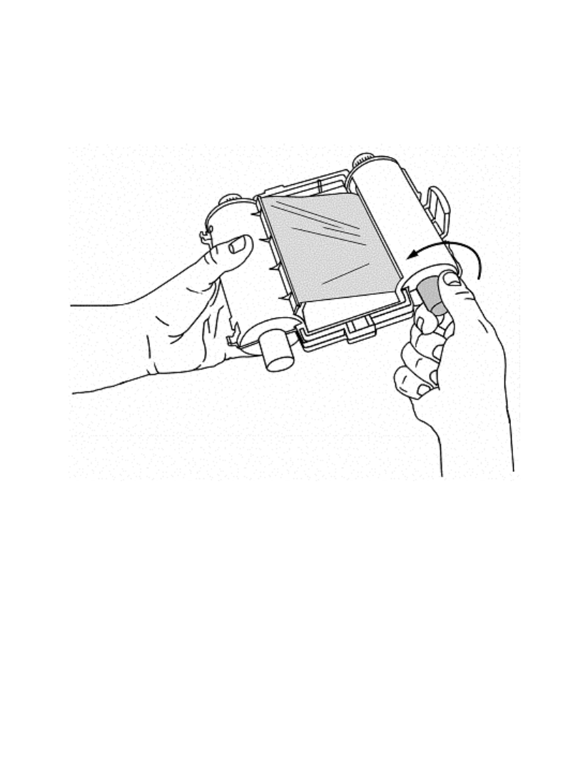
Figure 2-4. Adjusting the ribbon cartridge.
This will prevent any dust that may have accumulated on the ribbon from
transferring to the print head and affecting how your labels print.
Setting Up 2-7
Installing a tape cartridge
There are three simple steps to installing a tape cartridge: (1) adjusting the tape
cartridge receptacle to accommodate the width of the tape, (2) dropping in the
cartridge, and (3) feeding the tape through the advance rollers.
Adjusting the tape receptacle
Since the printer accepts tape widths from .5 inches (25 mm) to 4 inches (102 mm),
you must use the tape guides to adjust the tape receptacle inside the printer to
accommodate the size of the cartridge you are installing.
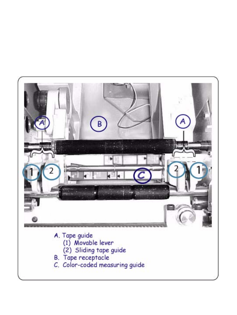
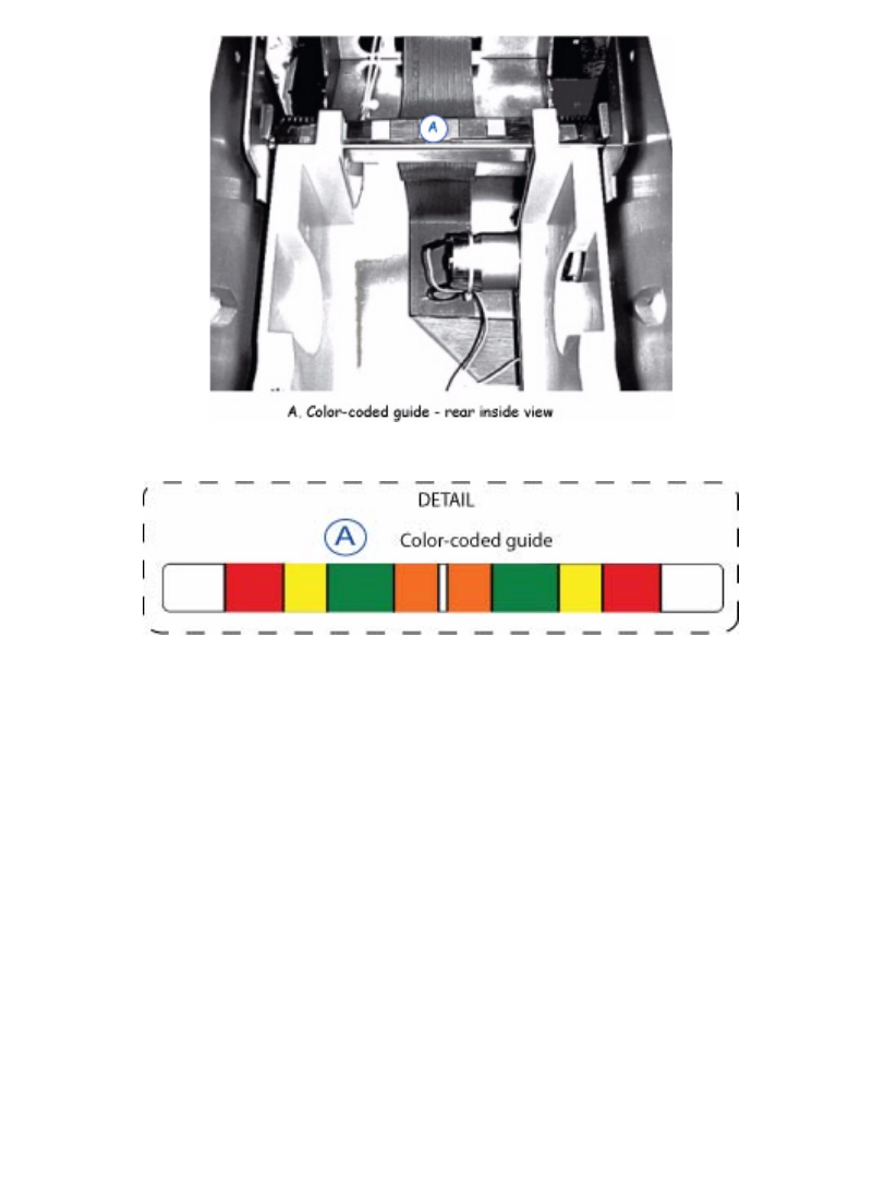
Figure 2-5. Tape guide, print tape receptacle and color-coded measuring guide.
2-8 Installing supplies
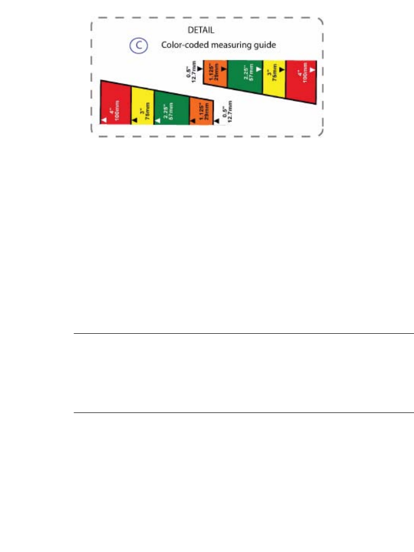
Figure 2-6. Color-coded measuring guide detail.
Step 1: Verify your tape’s size by noting the colored label in the center of the tape
cartridge’s handle. For example, if your tape is 4”, you will see a red label in the
center of the tape handle. That red label corresponds to the red bar on the color-
coded measuring guide (Figure 2-6).
Step 2: Grasp both tape guides. Note: Each tape guide is made up of two parts: a movable
lever (1) and sliding tape guide (2) (Figure 2-5). Squeeze the movable lever and
sliding tape guide together to position them.
Step 3: Align the tape guides to the corresponding color on the measuring guide. Be certain
to also match the arrows on the tape guides with the arrows on the measuring guide
to ensure the guides are aligned properly. The tape guides will lock in place. (For
example, if your supply is 4”, align both tape guides with the arrows on the red
bars on each side of the measuring guide.)
Important! Be certain to center justify the guides and make sure that each
guide is equidistant from the edges of the inside of the printer.
This will ensure that the tape is perfectly centered when it’s
installed. If the guides aren’t centered when you install the tape,
you will get an error message saying that the tape was not
properly installed.
Setting Up 2-9
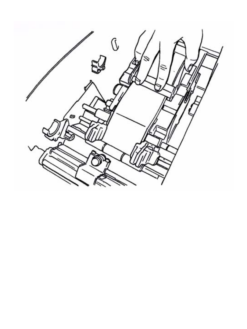
Inserting the tape cartridge
Figure 2-7. Installing a tape cartridge.
Step 4: Hold the tape cartridge by the handle with the feet pointed downward and parallel
with the surface the printer is sitting on, as shown in Figure 2-7. Make sure the tape
extends through the slot in the cartridge.
Step 5: Slowly lower the tape cartridge until the tape roller cylinder ends nest in the
circular slots of the tape receptacle.
.
2-10 Installing supplies
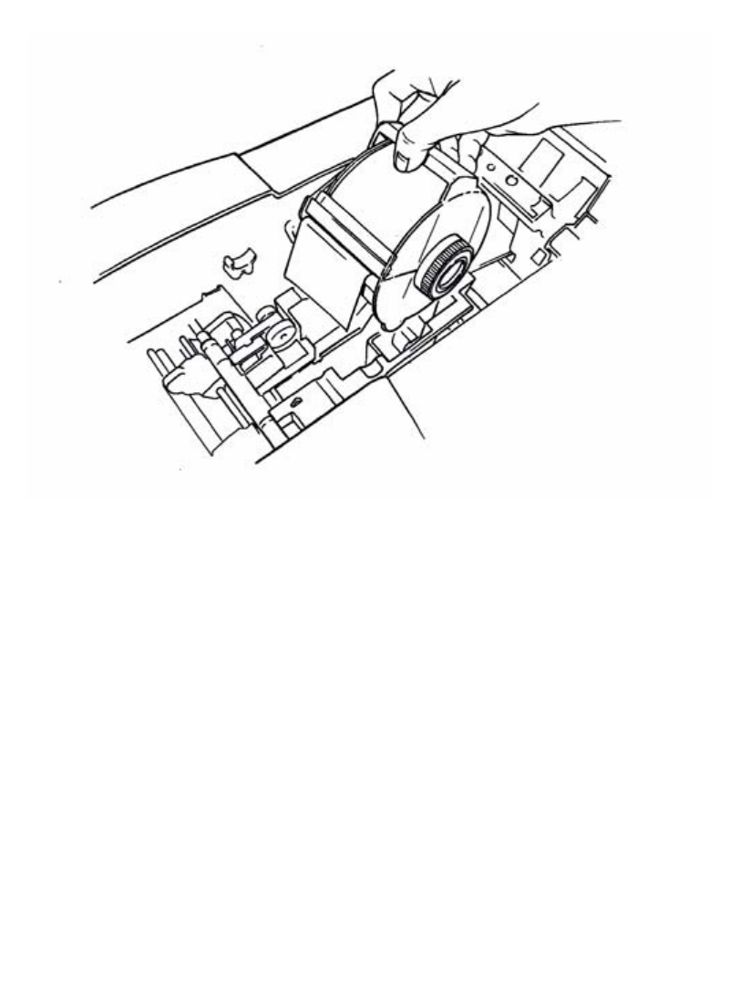
Advancing the tape
Step 6: Advance the tape over the first roller with your hand as shown in Figure 2-8:
Figure 2-8. Advancing the tape.
Step 7: Place the end of the tape between the tape guides as shown above in Figure 2-8.
Step 8: Advance the tape only halfway through the guides
Step 9: Your tape is now installed.
Step 10: As you are positioning the tape, the color-coded measuring guide may become
obstructed. Use the corresponding color-coded guide in the rear of the printer (see
Figure 2-9 and Figure 2-10) to assist you as you position the tape.
Setting Up 2-11
Figure 2-9. Color-coded guide - rear inside view.
Figure 2-10. Color-coded guide - rear inside view detail.
Closing the printer cover
Close the printer cover when you are finished installing the supplies. When the
cover closes, your printer reads the memory cells in the ribbon and tape cartridges,
and updates the supply attributes - the color choices available, the size parameters
and label lengths allowed - that will be applied to the labels you compose.
2-12 Installing supplies
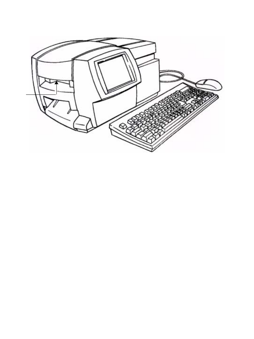
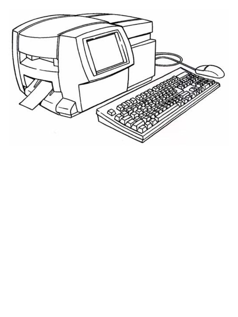
You’re ready to print!
Figure 2-11. The complete label printing system, with optional mouse.
Setting Up 2-13
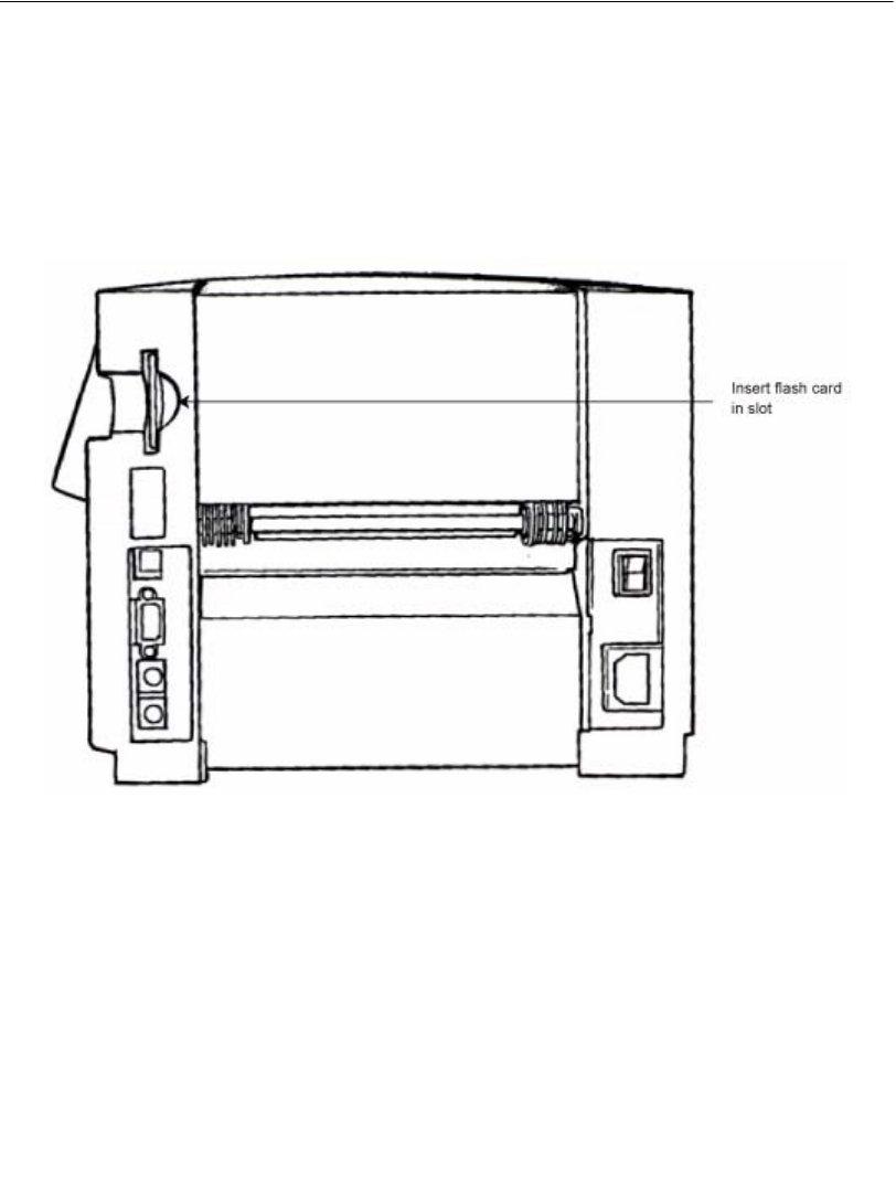
Installing a compact flash memory card
Your label printing system has a card slot you can use to attach a compact flash
memory card to your system.
Memory cards provide additional storage besides your printing system’s internal
storage. You can save labels as files in folders to this external memory, then open
them and edit or print them, and save them again.
The compact flash memory card slot is shown here
Figure 2-12. Compact flash memory card slot.
Hold the card so that the edge with the two rows of small holes is facing the card
slot (with the card logo facing the front of the printer), and gently insert the card
into the slot.
Note: The unit should be powered down before inserting or removing memory
cards.

2-14 Cleaning your system
Cleaning your system
If you notice streaks or scratches in your labels, it may be time to clean the print
head.
You can purchase a cleaning kit, which includes:
zA plastic bottle (to contain Isopropyl alcohol, minimum 90% alcohol, You must
purchase the alcohol separately.)
zTwo foam tip swabs
To clean the print head:
Step 1: Turn the printer power off.
Step 2: Remove the ribbon cartridge.
Step 1: Pour Isopropyl alcohol into the plastic squeeze bottle provided in the cleaning kit.
Step 2: Apply the Isopropyl alcohol to one of the swabs.
Step 3: Clean the print head with the wet swab, using a swiping motion across the print
head. The print head is behind the ribbon cartridge, identifiable by the green
horizontal line. The area to clean is the upper edge of the print head (above the
green line).
Step 4: Repeat with a clean swab to ensure that the print head is clean.
Note: Only use a swab once per cleaning. To keep new swabs free of dust, store
them in the plastic bag provided. Replacement cleaning kits are available.
If you have the Color & Cut system, you may occasionally want to clean the cutter
stylus as well. For instructions for cleaning the stylus and for replacing it as well,
see Appendix B: Cutter Maintenance.

3-2 Launching Your System
Launching Your System
When you turn on the power for your system, a decorative screen (also called a
“splash screen”) displays briefly while your system powers up.
When the system is ready to use, the Main Menu screen displays, providing you
with a choice of buttons you use to access system functions, files you may have
created, sets of pre-designed template labels, and applications designed for
producing specialty labels.
The Main Menu
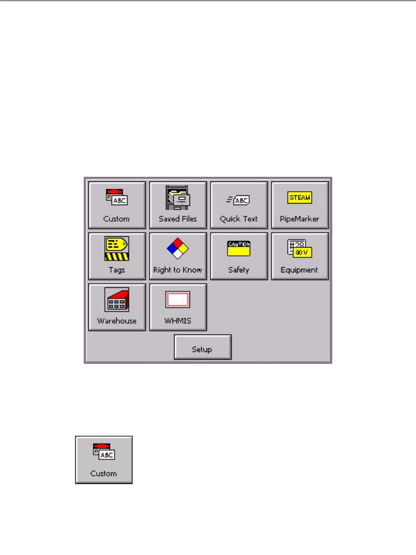
This is a sample Main Menu screen:
Figure 3-1. The Main Menu screen.
Your Main Menu screen may not contain all choices this one shows, or it may
contain additional choices not shown in Figure 3-1, depending on the applications
that have been installed in your system:
Custom, for creating and designing your own labels without
using pre-designed layouts or templates.(See Creating Custom
Labels on page 6-2 for more information.)
Starting Up 3-3
Saved Files, for accessing stored label files you previously
saved. (See CHAPTER 9: Working with Files, beginning on
page 9-1, for more information.).
QuickText, for creating text-only labels quickly and easily. (See
Creating QuickText Labels on page 6-5 for more information.)
Pipe Marker, with pre-designed layouts for creating standard,
roll-form, or symbol and arrow labels for marking pipes.(See
Creating Template Labels on page 6-11 for more information.)
Tags, with pre-designed layouts for creating hazard prevention,
maintenance, production, and quality labels you can print on tag
stock or adhesive-backed stock. (See Creating Template
Labels on page 6-10 for more information.)
Right to Know, with pre-designed layouts for creating U.S.
Occupational Safety and Health Administration (OSHA)-
compliant chemical warning labels.(See Creating Template
Labels on page 6-10 for more information.)
Safety, with pre-designed layouts for creating Caution, Notice,
Danger, and other warning labels. (See Creating Template
Labels on page 6-10 for more information.)
Equipment, with pre-designed layouts for creating equipment
placards, panel and switch labels, bin and shelf labels, and
property or asset identification labels. (See Creating Template
Labels on page 6-10 for more information.)
Warehouse, with pre-designed layouts for creating warehouse
facility labels such as shelf, rack, and bin labels, or production
quality control labels. (See Creating Template Labels on
page 6-10 for more information.)
WHMIS, with pre-designed layouts for creating Workplace
Hazardous Materials Information System-compliant chemical
warning labels, with safe-handling procedures for hazardous
products in the workplace.(See Creating Template Labels on
page 6-10 for more information.)
3-4 Keyboard Basics
Note: WHMIS is available on North American systems only.
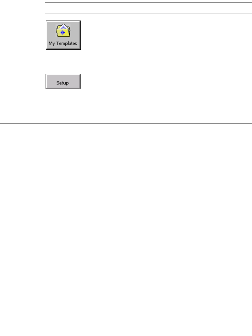
My Templates, where templates that have been downloaded,
copied, or moved to a folder using the File Management Utility
are stored. This option appears only if you have downloaded
templates new to your system. (See Using My Templates on
page 9-12 for more information.)
The button at the bottom of the screen access system features:
Setup, which you choose to set your system preferences. (See
CHAPTER 5: Setting Preferences, beginning on page 5-1, for
instructions.)
Keyboard Basics
You use your printing system’s keyboard to enter text characters on labels you
create or change, and to access certain system functions available only with special
function keys.
You’ll find descriptions of all keyboard keys and common keyboard functions,
including the familiar PC functions, the special print system functions, and
common operations you perform using the keyboard, in the sections that follow.
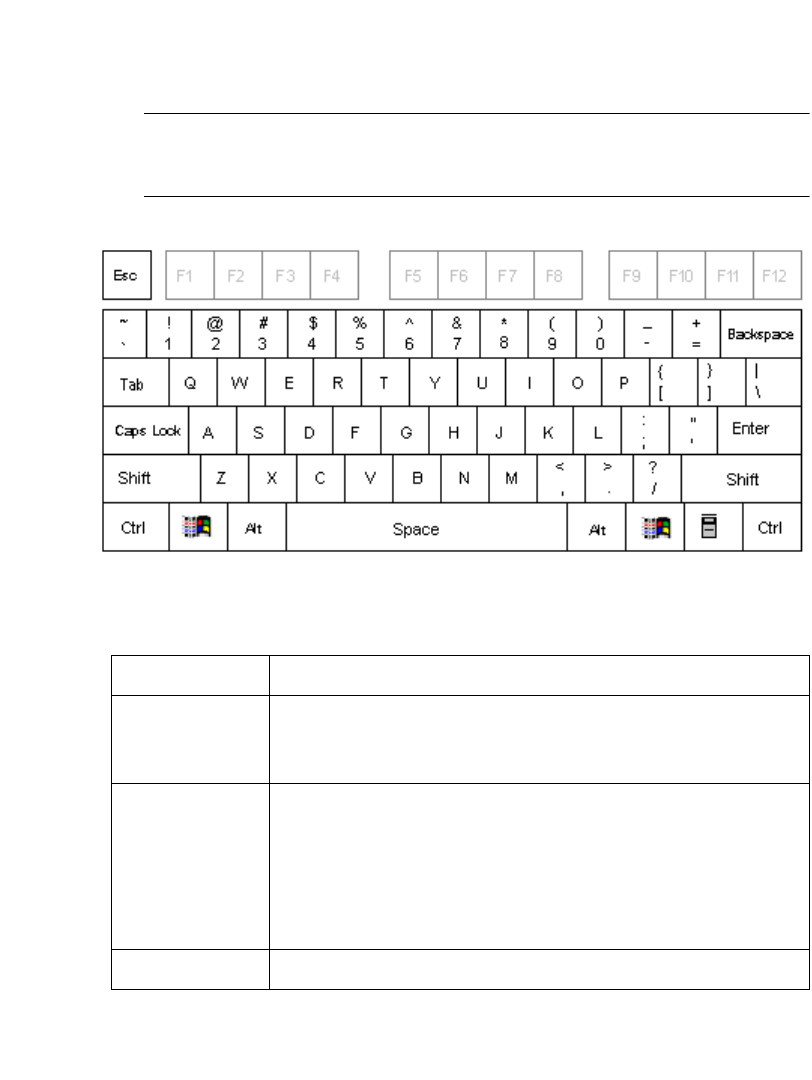
Starting Up 3-5
The standard keyboard
The standard PC keyboard provided with your system is divided into four sections
for purposes of description in this manual:
zSystem function keys unique to this printing system, page 3-5
zAlphabetic keys and functions, page 3-9
zArrow and command keypads, page 3-11
zNumeric keypad and functions, page 3-14
System function keys
The function keys (or F keys) along the top row of the keyboard perform specific
operations. The label above the F key row shows the functions available for each
key. Each key has one or two functions:
Primary function keys are used most often, so they require a single key press
to access the function.
Secondary function keys are used less often, so they require that you hold
down the Alt key along with the appropriate F key to access the function.
Primary
functions
Print File
Opt
Label
Prop
Add
Label
Next
Label
Edit
Object
Insert
Object
Scale Copy Paste Undo Menu
Secondary
functions
Cancel
Print
Adv &
Sheer
Clear Edit
Data
Prev
Label
Object
Prop
Object
Color
Help Status Pref
F10
Figure 3-2. The system function keys
Table 3-1 lists definitions of the system function keys.
F1 F2 F3 F4 F5 F6 F7 F8 F9 F11 F12
3-6 Keyboard Basics
.
TABLE 3-1. System function keys and definitions
Function Key(s) Description
Print F1 Displays the Print screen.
File Options F2 Displays the File Options screen, which provides
options you use to save, retrieve, or delete files.
Label
Properties
F3 Displays the Label Properties screen, which
provides options you use to change default
properties settings for your labels.
Add Label F4 Creates a new label or begins the prompt sequence
for creating a new label.
Next Label F5 Displays the next label in the set. If there is no
label beyond the current one, the system beeps.
Edit Object F6 Opens the selected object for editing, displaying
the screen used to create the object (text prompt,
graphic selection, bar code attributes, and so on).
If you have not selected an object, the system
beeps.
Insert Object F7 Displays the Insert Object screen, which you use
to select the type of object to insert: text, variable
text, bar code, graphic, HotShape, and so on.
Scale F8 Displays the Scale screen, allowing you to specify
a scale percentage for the select object. If no
object is selected, the system beeps.
Copy F9 Copies the selected object and makes it available
for pasting into a new location, leaving the
original in its current location (the standard
Microsoft Windows “Copy” function). If no
object is selected, the system beeps.
Starting Up 3-7
Paste F10 Pastes the object in memory into a new location
on the label (the standard Microsoft Windows
“Paste” function). If nothing has been copied into
memory previously, the system beeps.
Undo F11 Reverses the previous action. Undo affects the
most recent set of editing changes to an object. If
the previous action cannot be undone, the system
beeps. Undoing the last several actions is possible
in some cases, depending on system memory.
Redoing actions is not supported.
Menu F12 Closes the current application and displays the
system’s Main Menu screen, allowing the user to
select a different application without restarting the
system.
Cancel Print Alt+F1 Displays the Cancel Job screen, allowing the user
to cancel a print job regardless of what is
displayed on the screen.
Advance &
Shear
Alt+F2 Advances the supply such that any printing
currently under the print head clears the cutter and
shears it from the tape. “Shear” should not be
confused with the cut operation performed by the
plotter cutter (cutting out shapes, label borders,
etc.).
Clear Alt+F3 Displays the Clear screen, providing options for
the user to clear the current label or all labels in
the current set.
Edit Data Alt+F4 Active in the Pipe Marker and Right-to-Know
specialty applications only. Provides access to the
prompt screens so you can edit objects.
Note: Substitutes for the Edit Object key, which
is unavailable in Pipe Marker and Right-to-Know.
Previous Label Alt+F5 Displays the previous label in the file. If there is
no label prior to the current one, the system beeps.
TABLE 3-1. System function keys and definitions (Continued)
3-8 Keyboard Basics
Object
Properties
Alt+F6 Displays the property screen for the selected
object. Use the Properties screens to set attributes,
such as absolute position, rotation, special text
attributes, and so on. If no object is selected, the
system beeps.
Object Color Alt+F8 Displays the Object Color screen (same effect as
selecting the Color toolbar button). If no object is
selected, the system beeps.
Help Alt+F10 Displays the online help screen for the system.
Status Alt+F11 Displays information about the current machine
status, such as the OS version number and the
installed supply width.
Preferences Alt+F12 Displays the preferences screen for the application
you are using when you press the Preferences
key.
TABLE 3-1. System function keys and definitions (Continued)
Starting Up 3-9
Alphabetic and command keys
The standard key section of the PC keyboard provided with your printing system
has both alphabetic character keys and command keys.
Note: Blank keys in Figure 3-3 are not operational in this system. Grayed out
keys are system function keys, described in System function keys on
page 3-5.
Figure 3-3. Alphabetic character and command keys
TABLE 3-2. Keyboard keys definitions.
Key Description
Alphabetic
characters
Enters lowercase character text for labels and to enter
information in entry screens. Press alphabetic character keys in
combination with the Shift key to produce uppercase characters.
Numeric
characters
Enters numbers. Press numeric character keys in combination
with the Shift key to produce symbols shown on the key face.
(Alternatively, you can type numbers by pressing Num Lock on
the numeric keypad and use the numeric keypad numbers. See
Numeric keypad on page 3-14 for information.)
Note: This procedure may differ outside North America.
Esc Same as choosing Cancel on a system screen.
3-10 Keyboard Basics
Tab zAdvances to the next option on a screen.
zIn the Enter Text screen, adds a tab indent in the text entry
area.
zCycles through multiple objects layered on the display screen.
Caps Lock Locks on the uppercase for each alphabetic key. This function is
a toggle. If Caps Lock is off, pressing the Caps Lock key turns
caps lock on. Pressing it again turns it off. The Caps Lock LED
indicates the current caps lock status.If Caps Lock is on,
pressing Shift and an alphabetic key prints a lower case letter,
just like on a computer keyboard.
Shift Makes the next key pressed uppercase when Shift key is held
down. With Caps Lock is on, Shift makes the next key pressed
lowercase.
When an object is selected, press Shift and an arrow key to
move the object by greater increments than if you use the arrow
keys alone.
In text entry fields, press Shift in combination with the arrow
keys to select characters.
Ctrl Used in combination with specific alphanumeric keys, provides
keyboard “shortcuts” to certain standard Windows functions,
such as copying and pasting. See Shortcut keys on page 3-16
for specific details
Disabled.
Disabled
Alt Used in combination with the system function keys to access
secondary functions.
TABLE 3-2. Keyboard keys definitions. (Continued)
Starting Up 3-11
Arrow and navigation keypads
Space Also called Spacebar. Enters a space character or blank space
the size of a single character in text entry fields. Also, with a
radio button or checkbox, you can use the Space key as a
toggle: if the radio button is active or the checkbox is checked,
pressing Space inactivates the button or removes the check,
and vice-versa.
(Backspace)
Deletes the character to the left of the cursor. When the cursor is
at the beginning of a line other than the first line of a text entry
or edit field on a dialog, pressing Backspace removes the line
break.
↵Enter
Indicates the end of a line when entering text in a multi-line text
field. Moves the cursor down to the beginning of the next line.
On screens with entry fields, in most cases Enter is the same as
selecting Next or OK, indicating that you have completed
entries on the screen.
TABLE 3-2. Keyboard keys definitions. (Continued)
3-12 Keyboard Basics
Use the arrow and navigation keypads to move around on the screen or to delete an
item.
Note: Keys shown grayed out are inactive in this system.
Figure 3-4. Arrow and navigation keypads.
TABLE 3-3. Keypad keys descriptions
Key Description
Home Used within a text entry field to return the cursor to the left of the
first character
Delete Within an edit field on a dialog box, deletes the character at the
cursor position. If the cursor is positioned at the end of a line in a
multi-line text entry field, pressing the Delete key removes the line
break
End Used within a text entry field to return the cursor to the end of the
text (that is, in a multi-line text entry field, the cursor is placed to the
right of the last character, not at the end of a line.
Moves the cursor up one line at a time in the Enter Text screen. In
the Editor window, use to move selected objects one character space
at a time in the direction indicated by the arrow, or use with Shift
held down to move selected objects at a greater increment.
Starting Up 3-13
Moves the cursor down one line at a time. In the Editor window and
in text entry fields, use to move selected objects one character space
at a time in the direction indicated by the arrow, or use with Shift
held down to move selected objects at a greater increment.
Moves the cursor to the left one character at a time. If the cursor is at
the beginning of a line, moves it to the end of the line above. In the
Editor window and in text entry fields, use to move selected objects
one character space at a time in the direction indicated by the arrow,
or use with Shift held down to move selected objects at a greater
increment.
Moves the cursor to the right one character at a time. If the cursor is
at the end of a line, moves it to the beginning of the line below. In the
Editor window and in text entry fields, use to move selected objects
one character space at a time in the direction indicated by the arrow,
or use with Shift held down to move selected objects at a greater
increment.
TABLE 3-3. Keypad keys descriptions (Continued)
3-14 Keyboard Basics
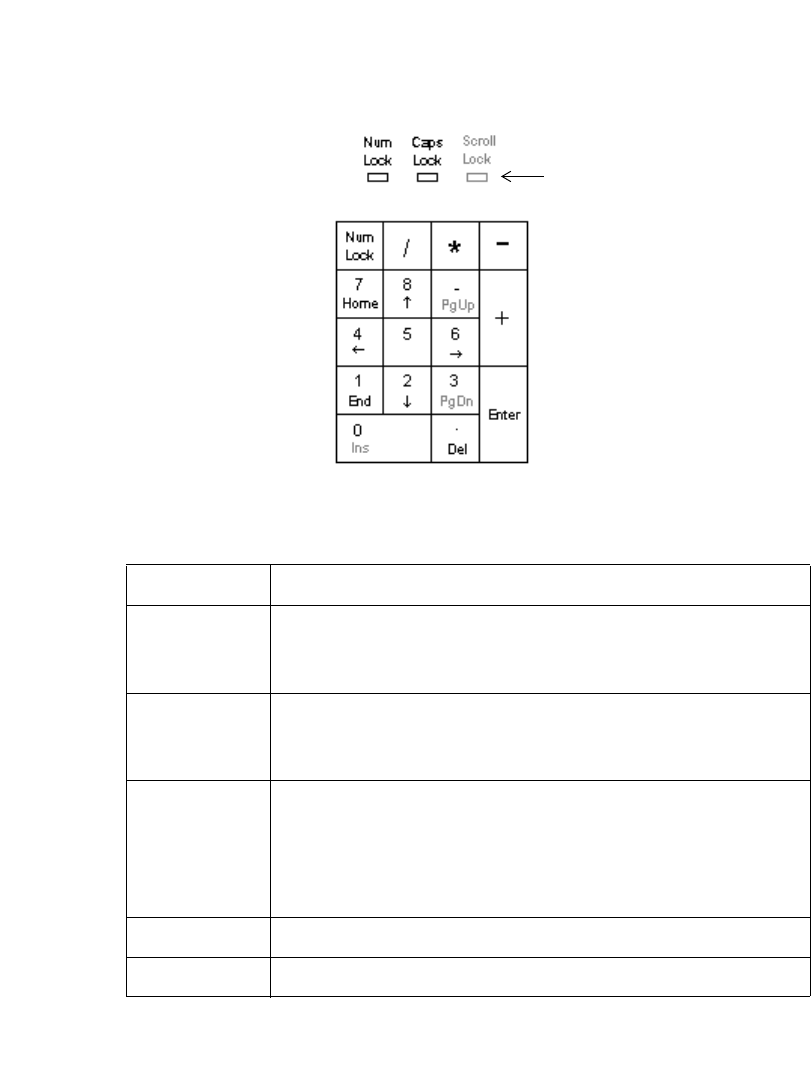
Numeric keypad
Use the numeric keypad as an alternate way to enter numbers and to perform
several other commands as well. The LED displays above the numeric keypad light
up to indicate the status of the functions named.
Figure 3-5. The numeric keypad and LED indicators.
TABLE 3-4. Numeric keypad keys definitions
Key or LED Description
Num Lock
LED
The Num Lock LED indicates the current Num Lock status.
When the light is ON, the number keys are active. When the
light is OFF, the command and arrow functions are active.
Caps Lock
LED
When lit, indicates Caps Lock (on the keyboard) is ON, which
lets you type in all uppercase (or capital) characters. When OFF,
alphabetic characters are in normal, lowercase form.
Num Lock Toggles (or turns on and off) the ability to type numbers using
the numeric keypad. (Numbers on the top row of the alphabetic
keyboard are always accessible.) When ON, press any key to
type that number. When OFF, pressing a key results in the
secondary function of that key.
/ (slash) Types slash character. Num Lock does not affect this key.
* (asterisk) Types asterisk character. Num Lock does not affect this key.
LED lights (ON
and OFF)
indicators
Starting Up 3-15
- (hyphen or
minus sign)
Types hyphen or minus sign character. Num Lock does not
affect this key.
Home With Num Lock OFF, when entering text in an entry field,
returns the cursor to the beginning of the field, left of the first
character. With Num Lock ON, types the number 7.
End With Num Lock OFF, when entering text in an entry field,
moves the cursor to right of the last character entered. With
Num Lock ON, types the number 1.
Del With Num Lock OFF, deletes the character at the cursor
position. If the cursor is at the end of a line, deletes the line
break. With Num Lock ON, types the period character.
+ (plus sign) Types plus sign character. Num Lock does not affect this key.
Enter Indicates the end of a line when entering text in a multi-line text
field. Moves the cursor down to the beginning of the next line.
Also, on screens with entry fields, Enter is the same as
selecting Next or OK, indicating that you have completed
entries on the screen. Num Lock does not affect this key.
Moves the cursor up one line at a time in the Enter Text screen.
In the Editor window, use to move selected objects one
character space at a time in the direction indicated by the arrow,
or use with Shift held down to move selected objects at a greater
increment.
Moves the cursor down one line at a time. In the Editor window
and in text entry fields, use to move selected objects one
character space at a time in the direction indicated by the arrow,
or use with Shift held down to move selected objects at a greater
increment.
Moves the cursor to the left one character at a time. If the cursor
is at the beginning of a line, moves it to the end of the line
above. In the Editor window and in text entry fields, use to
move selected objects one character space at a time in the
direction indicated by the arrow, or use with Shift held down to
move selected objects at a greater increment.
TABLE 3-4. Numeric keypad keys definitions (Continued)
3-16 Mouse Basics
Shortcut keys
In addition to the key functions listed above, the system provides some shortcut key
combinations for frequently-used system function keys or key combinations. You
may prefer to use these shortcut keys instead of the system function keys,
especially if you are an experienced Microsoft Windows user.
Table 3-5 lists the shortcut keys and their definitions::
Mouse Basics
Attaching a mouse is not necessary for using this printer, but if your system is
equipped with a mouse, you can use it to select items on labels, to move items on
labels, to click buttons on screens, and to navigate on screens.
Moves the cursor to the right one character at a time. If the
cursor is at the end of a line, moves it to the beginning of the line
below. In the Editor window and in text entry fields, use to
move selected objects one character space at a time in the
direction indicated by the arrow, or use with Shift held down to
move selected objects at a greater increment.
TABLE 3-5. Shortcut keys definitions.
Ctrl + C The standard Windows “Copy” function, which copies the
selected text or object so you can paste it in another location.
Ctrl + V The standard Windows “Paste” function, which pastes the
previously copied text or object.
Ctrl + X The standard Windows “Cut” function, which deletes the the
selected object.
Ctrl + Z Undoes the previous action (when possible).
Shift +
Arrow
Used to select text in a text entry field. Use also to reduce or add
to the text already selected.
TABLE 3-4. Numeric keypad keys definitions (Continued)

Starting Up 3-17
Using a mouse on labels
You can use any of several methods to select a text object or graphic on a label you
are previewing in the Editor window, depending on your preference and the
equipment your system offers.
To select an item on a label
Use the mouse to move the cursor to the item and click the left mouse button. The
item is highlighted with selection markers to indicate that it is selected.
To select multiple items on a label
Hold down the Shift key, then click on the first item, continue to hold Shift, then
click on the second item, and so on.
To move items on a label
Move the mouse cursor to the item, click on it to select it, and hold the left mouse
button down.
The mouse cursor changes to a four-way movement cursor, which indicates that
you can “drag” or move the selected object in any direction.
Release the button when finished.
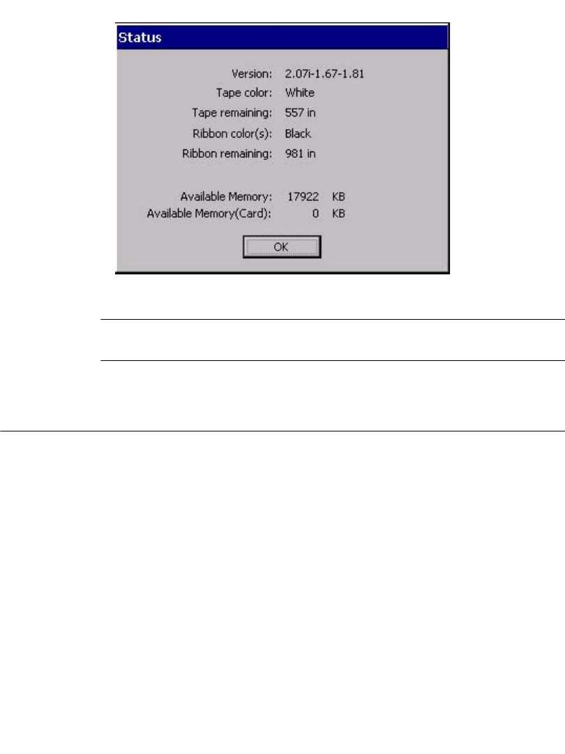
Checking System Status
To check how much tape or ribbon you have left, or the color of the ribbon installed
in your system, press the Status key (Alt+F11). The system Status screen, shown
here, also tells you your system’s version number and current available memory.
3-18 Accessing Online Help
Figure 3-6. The Status screen.
Hint! You can press the Status key at any time to access the system Status
screen.
Accessing Online Help
You can get help on tasks using either of two methods:
zPress the Help key (Alt + F10) on your keyboard at any time to display a brief
description of the editing tools.
zWatch the Status bar at the bottom of the Editor window. It displays
information about the task you are currently performing.

4-2 Working in the Editor window
Working in the Editor window
The Editor window is displayed at the beginning of the label creation process for
some labels, during the process and at the end of the process for all labels, and it is
displayed again when you open a saved label file for editing. You might think of it
as the palette upon which your labels are created and displayed.
Figure 4-1. The Editor window with label
When you create a label, you build it by creating or adding objects to it. The
system displays the objects in the Editor window in the Preview area. When
objects are displayed in the Preview area, you can move them around and make
changes to them. Objects can be text, graphics bar codes, and a variety of supplied
designs called HotShape.
In this manual, when we describe basic processes, we’ll refer to alphabetic and
numeric characters as text, and to all other objects as graphics. When we discuss
processes designed for specific objects, we’ll specifically name those objects: for
instance, Adding bar code objects on page 7-17, or Formatting text objects on
page 7-6.
The sections that follow describe the elements of the Editor window, how to
navigate inside it, and how to use its tools to perform basic editing procedures.
Preview
area
Toolbar
Scroll buttons
Status bar
Rulers
Basic Procedures 4-3
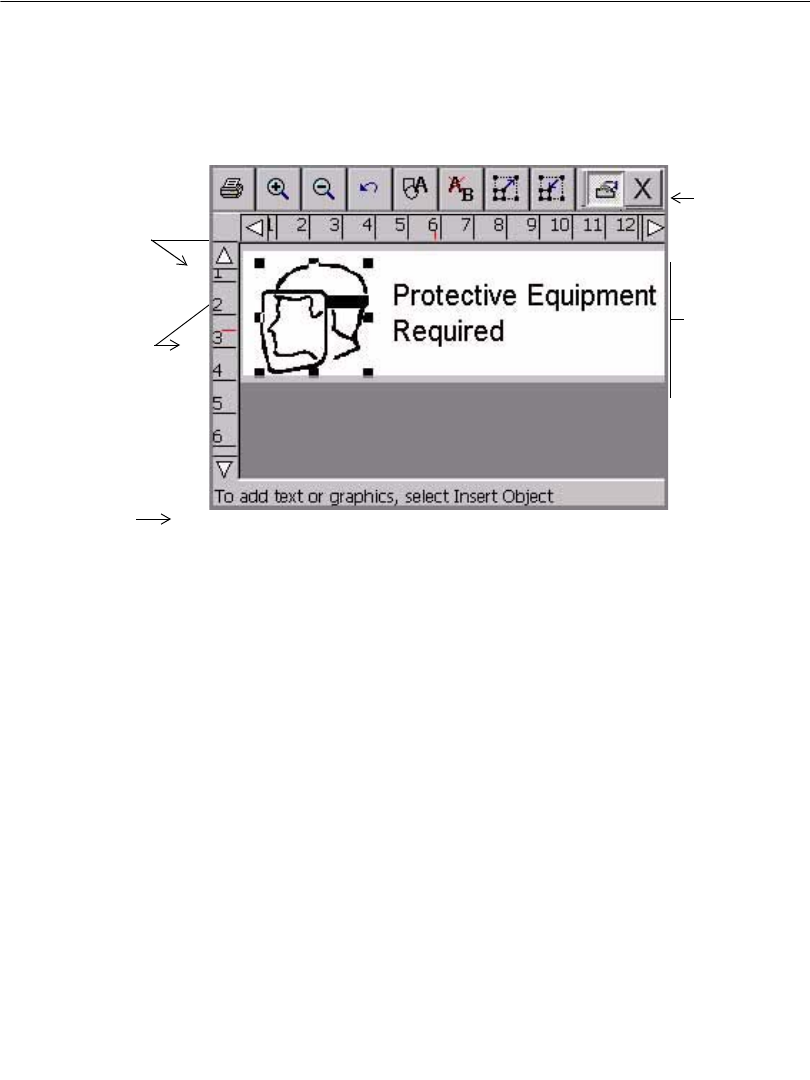
Inside the Editor window
Use these editing and navigation tools within the Editor window, shown in Figure
4-1, to create and to edit labels:
zThe preview area
zThe toolbar
zThe rulers
zThe scroll buttons
zThe status bar
The preview area
When you create a label, you build it by adding objects to it. You view the objects
on the Editor window in the Preview area. The system displays the objects in the
Preview area, shown in Figure 4-1, as you work. The Preview area also reflects the
size of the tape supply you have installed, and color (if you have a color display) of
the tape you have in the machine.
After you add an object or change an object, the system returns you to the Editor
window.
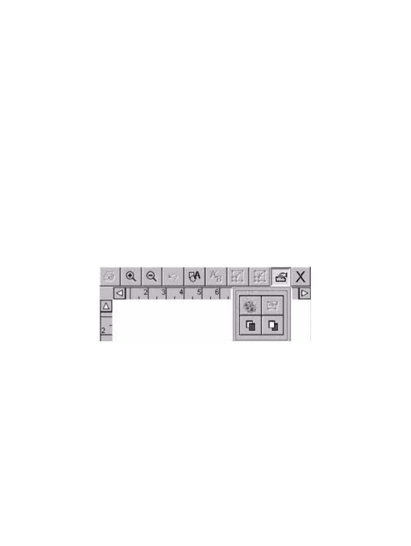
The Editor window toolbar
Figure 4-2. The standard Editor window toolbar
The standard Editor window toolbar appears at the top of the Editor window
(shown in Figure 4-1) and contains icons (or “buttons”) that represent the tools you
use to view, format, and print labels. You activate a tool using one of these
methods:
zTouch it on the screen.
zMove the cursor with the mouse, then click the left mouse button.
Some tools are active at all times, such as Zoom In and Zoom Out, and others
have no effect unless you have selected an object (such as Increase Size or
Decrease Size) or unless you have already performed some action (such as Undo).
4-4 Working in the Editor window
Hint! When a toolbar button is inactive, it is grayed out, or appears on the screen
as dimmer than the others.
The Editor window is used for all types of labels you create, but the Editor
toolbars vary according to which tools are appropriate for the type of label you are
working with.
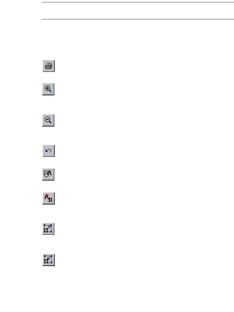
This is a complete list of Editor window tools:
Print. Follow the instructions on the Print screen to print your label. See
Printing on page 11-1 for details.
Zoom In. Increases the magnification, making the objects on the label
look larger. Does not change the actual size of the printed label, but is used
as a viewing aid. See Zooming in and zooming out on page 4-6 for
details.
Zoom Out. Decreases the magnification, making the objects on the label
look smaller. Does not change the actual size of the printed label, but is
used as a viewing aid. See Zooming in and zooming out on page 4-6 for
details.
Undo. Reverses the last action you performed, when possible. When
actions may not be undone, the Undo button is grayed out. See Undoing in
the Editor window on page 4-9 for details.
Insert Object. Allows you to select the type of object you want to insert in
the label, such as text, graphic, bar code, and so on. See Adding
Objects on page 7-3 for details.
Edit Object. Allows you to edit the object selected, depending on the type
of object. For example, for text, you’ll see the text editing screen. For
graphics, you’ll see the graphics selection prompt. See Opening and
editing an object on page 7-31 for details.
Increase Size. Increases the size of the selected text or graphic. The text or
graphic remains in its original proportions, but displays and will print 10%
larger for each time you press the Increase Size button. See Using
Increase Size and Decrease Size on page 7-28 for details.
Decrease Size. Decreases the size of the selected text or graphic. The text
or graphic remains in its original proportions, but displays and will print
10% smaller for each time you press the Decrease Size button. See Using
Increase Size and Decrease Size on page 7-28 for details.
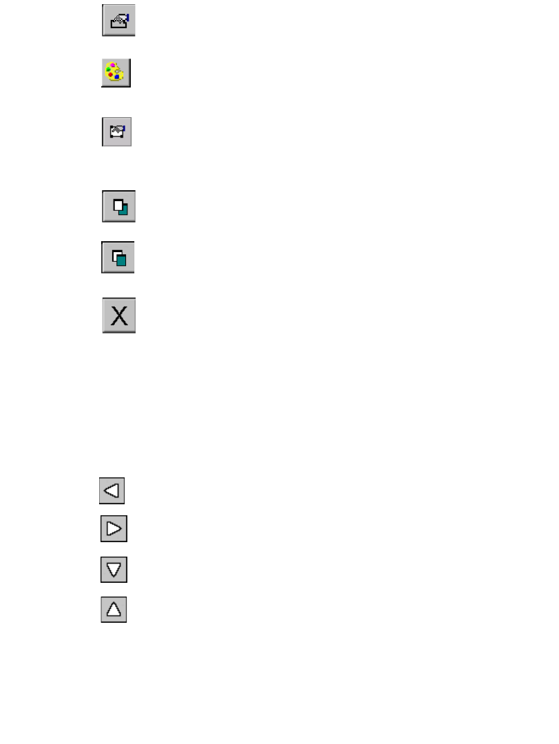
Basic Procedures 4-5
Properties Menu. Displays different options that apply to the object
selected including: Color, Object Properties, Move to Back, and Move to
Front.
Color. Lets you choose color for the selected object or change the default
color the system uses for drawing new objects. See See CHAPTER 8:
Applying Color, beginning on page 8-1 for details.
Object Properties. Lists information about the object selected, which can
be either text or graphic, including height, width, rotation, and so on. This
button is valid only when a single object is selected. See Changing object
properties on page 7-32 for details.
Move to Back. Moves the selected object to the back of any layered
objects, so that the other objects obscure or cover up the selected object.
Move to Front. Moves the selected object to the front of any layered
objects, so that the selected object obscures or covers up any objects
behind it.
Exit. Returns to the Main Launcher screen.
Scrolling functions
Use the scroll buttons (shown in Figure 4-1) to move the view shown on the screen
to the left or right, and up or down.
If the entire label is already visible in the viewing area of your screen, scrolling has
no effect. But if you have chosen a zoom level that results in your label exceeding
the size of the preview window, you’ll find the scroll buttons useful.
Press the left scroll button to shift the view toward the right edge of the
label.
Press the right scroll button to shift the view toward the left edge of the
label.
Press the down scroll button to shift the view toward the bottom edge of
the label.
Press the up scroll button to shift the view toward the top edge of the
label.
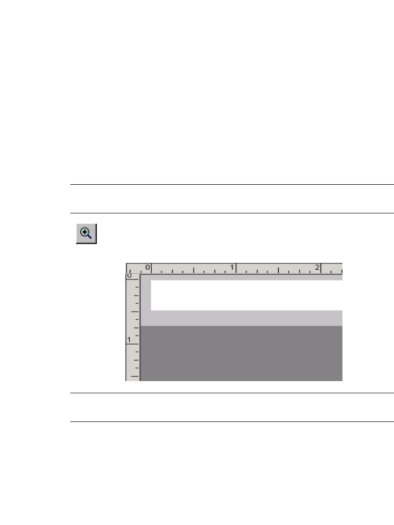
4-6 Working in the Editor window
To continue scrolling in the direction indicated
zPress and hold the scroll button.
zWith the mouse, click on the appropriate scroll button, and hold down the left
mouse button to continue to scroll.
Ruler functions
The horizontal and vertical rulers in the Editor window preview area (shown in
Figure 4-1) use the same scale. This means that each increment on the horizontal
ruler equals the same increment on the vertical ruler.
Zooming in and zooming out
Magnification changes by 25% each time you use a Zoom tool. As you use the
Zoom In or Zoom Out tools to change the view of your label in the preview area,
the numeric values shown on the rulers are increased or decreased accordingly.
Note: Zooming does not change the actual size of your label or the size of your
label objects. It only affects your view.
As the view zooms in, the magnification level increases, which means
that less of the label is visible, and the tick marks on the rulers appear to
be farther apart:
Hint! Zoom in to make your label display appear less cluttered and easier to
work with.
123456
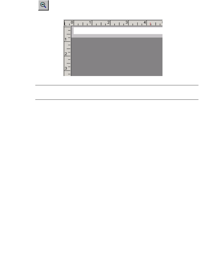
Basic Procedures 4-7
As the view zooms out, the magnification level decreases, which means
that more of the label is visible, and the tick marks on the rulers appear
closer together:
Hint! Here’s a quick way to zoom in or out by 100%:
Hold down Shift, then press Zoom in or Zoom out.
The status bar
The status bar displays a system message related to the task you are performing.
Sometimes the messages are instructive, as in Figure 4-1, which tells you how to
proceed to create your label. In some instances, such as when you are working with
sequence labels, the number of the label displayed is shown: for instance, Label 1
of 3, Label 2 of 3, and so on.
Editing procedures
Selecting in the Editor window
Before you can use many of the tools and features shown on the Editor window to
format a label, you must select the part of the label shown in the preview area of the
Editor window that you want to work on.
When you select an object, small squares or selection markers appear at the
corners and midpoints of the sides of a dotted-line box around the object. The
123456
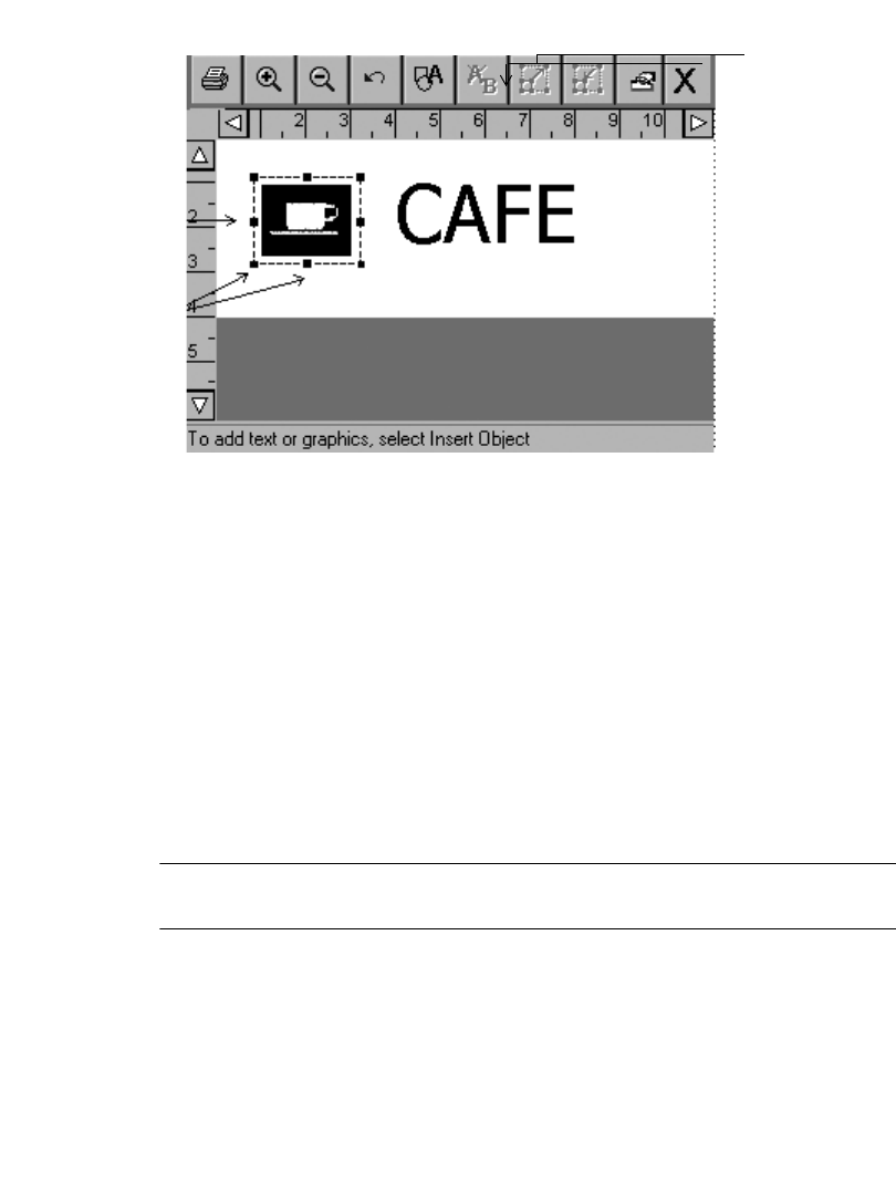
4-8 Working in the Editor window
dotted lines disappear, but the markers always indicate that you have successfully
selected the object, as shown here:
Figure 4-3. The Editor window with a graphic selected.
For instance, if you want to enlarge the coffee cup graphic in the label in Figure
4-3, you first select the graphic on the label using one of the methods described
below, then choose the Increase Size tool.
You can use either of the methods below to select an object in the Preview area on
the Editor window, depending on your preference and the equipment your system
offers:
zTouch the object you want to select. Selection markers appear around the
object, indicating that it is selected.
zUsing the mouse, move the cursor to the object and click the left mouse button.
The object is highlighted to indicate that it is selected.
The changes you make will apply only to the object you have selected.
Hint! When your label contains multiple objects, if any object is selected, you
can press <Tab> to cycle through the objects on the screen.
Selecting multiple objects
To select multiple objects on a label, hold down the Shift key, then use either of the
methods described above.
Selected
object
Selection
markers
Increase
Size tool
Basic Procedures 4-9
Deselecting in the Editor window
You can deselect an object after you perform an action on a selected object, or if
you change your mind before you make changes to the selected item.
To remove the selection markers, touch any non-highlighted area of the screen. If
you are using a mouse, move the cursor to a non-highlighted area and click the left
mouse button to deselect.
Undoing in the Editor window
You can use this tool to reverse or undo your most recent action in the Editor
window:
The Undo icon is not valid at all times, however, as some formatting actions cannot
be undone. When Undo is not possible, this icon will be grayed out (or appear to be
dimmer) on the toolbar.
Working in Entry Screens
Entry screens are screens upon which you enter the parts that make up your label
and in which you enter information about the design of your label. You enter label
text and information about your label by using:
zText entry areas
zEntry fields
zButtons
zCheckboxes
zRadio buttons
zSize adjustment buttons
Screens usually contain one or more of these information entry devices, as shown
in Figure 4-6 on page 4-12 and Figure 4-7 on page 4-13.
Some screens may show options or areas as dimmed, or grayed out. This indicates
that particular option is disabled, or not available on your system or in the context
in which you are operating.
Navigating in entry screens
You can move around inside entry screens by touch, keyboard, or mouse:
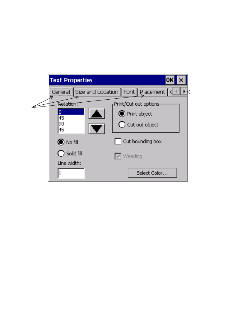
4-10 Working in Entry Screens
By touch: Simply touch the part of the screen you want to activate.
By keyboard: Press Tab to move between options or fields.
By mouse: Use the mouse to move the cursor to an option or field. Click the left
mouse button to choose the option or field.
Tabbed entry screens
Some entry screens contain additional tabbed screens with related options. Select
the tab to get to its options. Touch the scroll arrows to scroll to any additional tab
screens.
Figure 4-4. The Text Properties screen with tabs.
Tabs
Scroll arrows
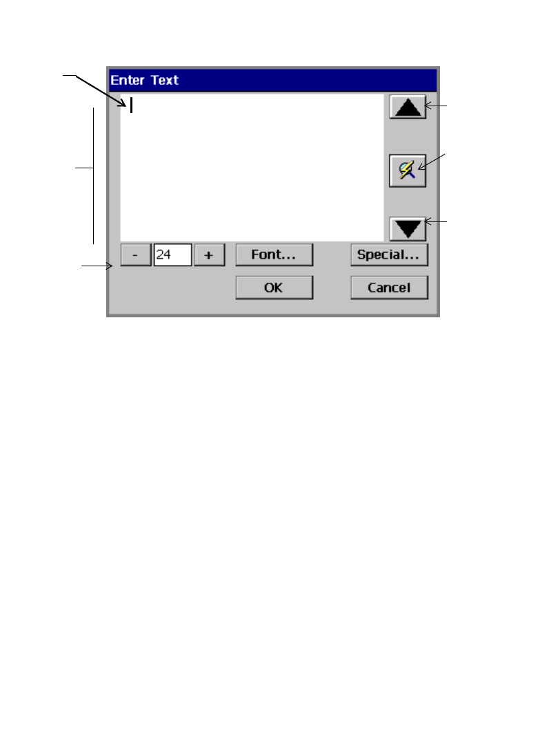
Basic Procedures 4-11
Entering information in entry screens
You construct your label text in a text entry area on the Enter Text screen, as
shown here:
Figure 4-5. The Enter Text screen.
You can get to the Enter Text screen by pressing <Insert Object> on the
keyboard, then selecting Text from the Insert Object screen. (See Adding Objects
on page 7-3.)
To enter text in a text entry area, type the characters on your keyboard. To start a
new line, press <Enter>.
Typing uppercase
To type text in UPPERCASE (or capital) letters, press the <Caps Lock> key. To
turn off uppercase, press <Cap Locks> again.
To capitalize a single character, hold down Shift and press the key.
Typing special characters
You can insert accented characters, subscripts, and other special characters that do
not appear on your keyboard on your labels by choosing the Special button on the
Enter Text screen. The Special Characters screen lets you enter codes that
automatically place the special character at the insertion point in your text entry
area. See Adding special characters to text on page 7-8 for detailed information.
Text
entry
area
Scroll
button
Size
adjustment
buttons
Cursor
(blinking) Scroll
button
Refresh Screen
button. Use when
entered text
exceeds the text
entry area.
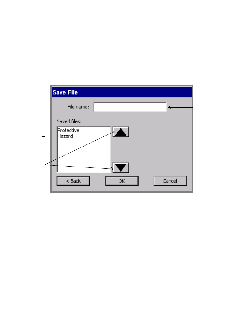
4-12 Working in Entry Screens
Choosing options
You enter your option choices on entry screens via entry fields, option buttons,
checkboxes, and other devices, described below.
Using entry fields
You type information directly into entry fields. Some entry fields are ready for
your entry as soon as you navigate to them, while others are associated with other
screen elements.
The File name field on the Save File screen is an example of an entry field
ready to accept your typed text:
Entry field
Scroll list
Scroll
buttons
Figure 4-6. The Save File entry screen.
An example of another type of entry field is the Labels from field in Figure 4-7
on page 4-13. In this field, you enter the beginning and end number for the
range of labels you want to print. This type of entry field is activated only when
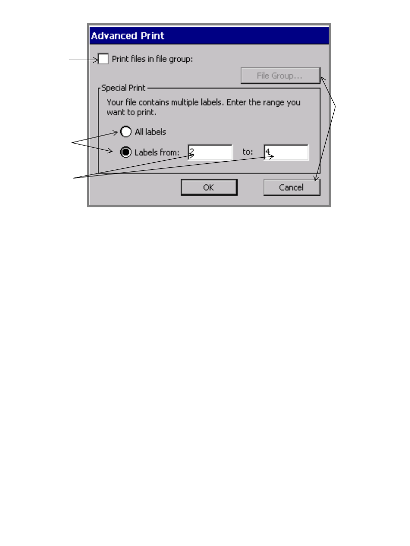
Basic Procedures 4-13
you choose the attached radio button. (See Using radio buttons on page 4-15
for more information.)
Option
Buttons
Checkbox
Radio
buttons
Entry
fields
Figure 4-7. The Advanced print entry screen.
Using option buttons
Touch an option button to implement the command or function listed on the button.
For instance, in Figure 4-7, the File Group button is disabled, but when it is active
it takes you to the File Group screen, where you choose a File Group to print. The
Cancel button cancels any entries you made on the Advanced Print screen, and
returns you to a previous screen.
4-14 Working in Entry Screens
Using option lists
Some fields provide lists of options from which you can choose, such as the
Density fields on the screen shown here:
Figure 4-8. The Bar Code screen, Dimensions Tab.
To select from an option list, touch the down arrow next to the field to see
the list of options. Then select an item on the list.
Using scroll lists
Figure 4-6 on page 4-12 shows an example of a scroll list. Scroll lists contain lists
of items for you to choose from. To make your choice, you can move up and down
the list using the scroll buttons, which are also shown in Figure 4-6. When you find
the item you want, touch or select it to choose it.
Hint! The scroll buttons duplicate the function of the up and down arrow keys.
Using checkboxes
Checkboxes with checkmarks inside indicate that an option is enabled. Empty
checkboxes indicate the option is not enabled. Figure 4-7 shows an example of a
checkbox.
To indicate your choice in a checkbox, touch the checkbox or click on it with the
mouse.
To see an
option list,
choose the
down arrow
next to the
field.
Closes the
screen without
saving your
entries.
Option list
Basic Procedures 4-15
For example, in Figure 4-7, check the Print Files in Group option checkbox to
indicate that you want to print a group of files all at once. Leaving it unchecked
indicates that you accept the default status, which is printing a single file.
Using radio buttons
Radio buttons are empty circles when not in use, and circles with dots inside when
activated. Figure 4-7 shows examples of radio buttons.
If there are one or more radio button options on a screen, you can activate only one
option at a time.
To choose a radio button option, touch the circle or move the cursor to it and press
Enter, or use the mouse to move the cursor to it and click the left mouse button.
Using size adjustment buttons
These adjustment devices appear in various places in the
system (for example, on the Font screen shown in Figure 7-4
on page 7-7), where you need to increase or decrease
dimension or magnitude.
Touch + to increase the dimension or magnitude.
Touch - to decrease the dimension or magnitude.
Exiting entry screens
You can always choose to save or to cancel your entries on an entry screen.
To exit an entry screen and save your entries
Press or choose OK or Next.
zThe OK button may be at the top right of the entry screen, as shown in Figure 4-
8, or it may be a full-sized button near the bottom of the screen, as shown in
Figure 4-7.
zNext takes you to the next screen you need to complete in the process.
To exit an entry screen without saving your entries
Use one of these methods:
zPress or choose the X button, as shown in Figure 4-8.
zPress or choose Cancel, as shown in Figure 4-7.
zPress Esc. You can also use the Back button when present to return to the
previous screen. Back does not save your information.

4-16 Working in Entry Screens

5-1
Your label printing system ships with pre-set settings called default system settings.
You can customize your system settings to reflect your own preferences.
This chapter tells you how to change system settings. Topics include:
Accessing System Setup
Setting Printing Tab Options
Setting Localization Tab Options
Setting Hardware Tab Options
Setting Other Tab Options
Sett ing Text Tab Opt ions
Setting On Line Tab Options
CHAPTER 5 Setting Preferences
5-2 Accessing System Setup
Accessing System Setup
When you change the pre-set system settings your system shipped with, you change
the default values your system uses to determine how your printer works. The
changes you make in the System Setup screens apply to your entire system.
Note: Be cautious about changing system settings. Remember that changes you
make will apply to your entire printing system.
To cancel changes and return to the default settings, touch or click the
Cancel button, shown at the left, while displaying any of the system
preference option tabs. Or press <Cancel> on your keyboard.
To access the System Setup settings options
1. Choose the Setup button on the Main Menu screen (shown in Figure 3-1 on
page 3-2).
You’ll see the System Setup screen, shown here:
Use Tab
arrows to see
additional
tabs, unless
grayed out.
Figure 5-1. The System Setup screen.
The System Setup screen has as many as six tabs with options. Five tabs are
visible at one time on the screen. You may see fewer tabs at times, depending on
where you are in the system.
Setting Preferences 5-3
The System Setup tabs are:
• Printing
• Localization
• Hardware
•Other
•Text
• On Line
The Tab arrows indicate the presence or absence of additional tabs. In Figure
5-1, for instance, the Tab arrows indicate that there are additional tabs to be
seen when you choose the right Tab arrow, but not if you select the left Tab
arrow.
2. Choose a tab to set those options.
You’ll find information about setting the tab options in the sections that follow.
3. Use the two buttons at the top right corner of the screen to:
Save the changes you made.
Return to the Main Menu screen or to the Editor window in some
cases, without saving changes.
5-4 Setting Printing Tab Options
Setting Printing Tab Options
The Printing options tab is shown in Figure 5-1. You specify your system’s print
job defaults on this tab. The options are:
Supply saver Turns basic multiple-up printing ON or OFF. The
default setting is OFF. The Supply saver printing feature
saves supplies by arranging labels of the same size
together in the print queue.This saves tape because it
stacks labels that are smaller than the full width of the
tape so that the full width of the tape is used, and it saves
ribbon because it groups labels to print within a set of
ribbon panels. (The sample in Figure 11-10 on page 11-
20 illustrates a print job with five separate labels that
have been stacked by supply saver.)
In addition, if you have the Color & Cut system, when
Supply saver is ON, your system cuts out each label
individually. See Checking Supplies on page 12-10.
Recalibrate
Columns during
Cutting
Applicable only when cutting out multiple labels using
the Supply saver option. If you select Recalibrate
Columns during Cutting, the printer rewinds the tape to
the leading edge after each column of labels is cut out,
making the cut output more accurate.
If Supply saver is not selected, this option is not
available.
Setting Preferences 5-5
For more information about printing options, see Printing Tab Options on
page 11-19.
Overprint Turns overprinting ON and OFF. OFF is the default.
Overprint controls the order in which colors are printed
on the label so that black prints last.
•With Overprint ON, black prints over (on top of) any
previously printed colors. This ensures that there will
be no gaps between colors and black print areas.
However, with Overprint ON, printing may be slower,
because the system must analyze the colors in the print
job and order them accordingly. You may have to swap
ribbons more often as well.
•With Overprint OFF, areas of colors that will print
behind black are removed before black is printed.
However, you may see a slight gap between the color
areas and the black areas.
Print Label
Boundary
Indicates the edge of the label.
Auto Cut Between
Labels
Lets you turn off the automatic shear between labels for
monochrome print jobs. When selected, the printer does
not shear between labels, letting you keep the output
together on the roll for use in another location.
Labels are sheared after 120” of printing (since that it the
maximum monochrome print length supported), and at
the end of the print job, even if Auto Cut Between
Labels is OFF.
Note: When Auto Cut Between Labels is OFF, the
output length of each label may shift from the true
defined label length because the system does not
continually find the front edge of the tape as the labels are
output. This should not be an issue for die-cut
monochrome jobs because the die-cut positioning routine
in the firmware registers the position of each label.
The Auto Cut Between Labels option is not used for
multi-pass print jobs, cut jobs, or when printing to
notched continuous supplies.
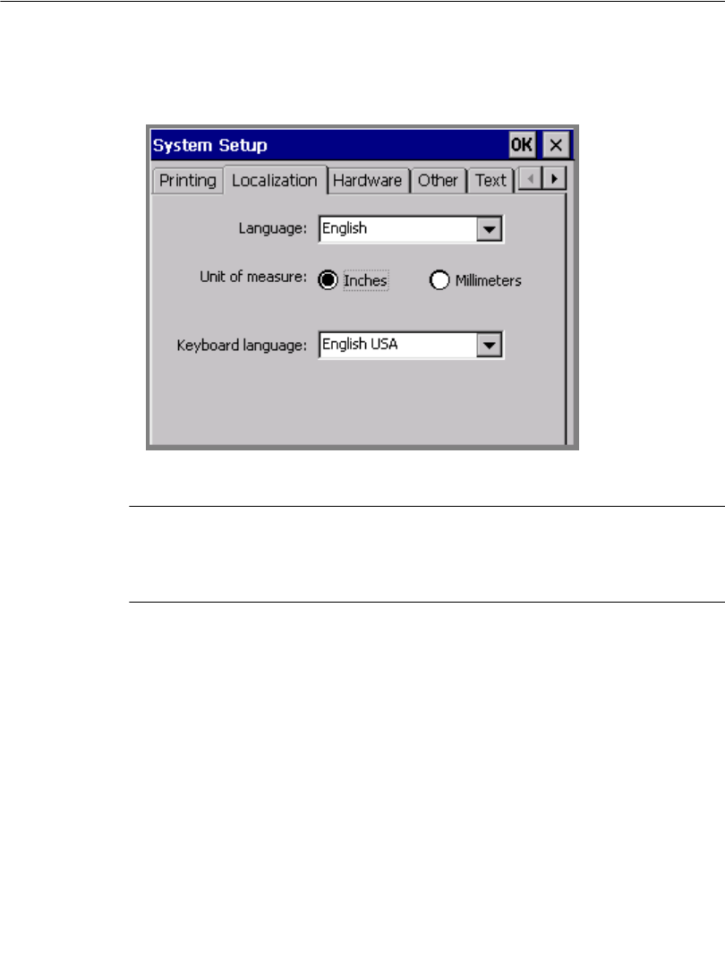
5-6 Setting Localization Tab Options
Setting Localization Tab Options
Use the options on the Localization tab to set your system’s text language,
keyboard language, and the unit of measure used in determining the size of your
labels:
Figure 5-2. The System Setup Localization tab.
Note: You must restart your system before Localization preferences that you set
take effect. After you make Localization option changes, choose OK, then
when the Main Menu screen displays again, turn your printer OFF and
ON again.
Setting Preferences 5-7
The options are:
Language Sets the language the system uses for the screens,
prompts, and messages. Language options available
depend on your system:
•North American: English (default), French,
Spanish
•Europe I: English (default), German, French,
Dutch
•Europe II: Spanish (default), Italian, Portuguese,
English
•Europe III: Danish (default), Finnish,
Norwegian, Swedish
Unit of measure Sets the unit of measure used in the system for
displaying label length, label width, and so on.
Options are:
•Inches
•Millimeters
The default unit of measure varies by country.
Keyboard
language
Sets the language for your system keyboard.
Available languages are:
•English - United Kingdom
•English - United States
•French
•German
•Spanish
•Italian
•Norwegian
The default language varies by country.
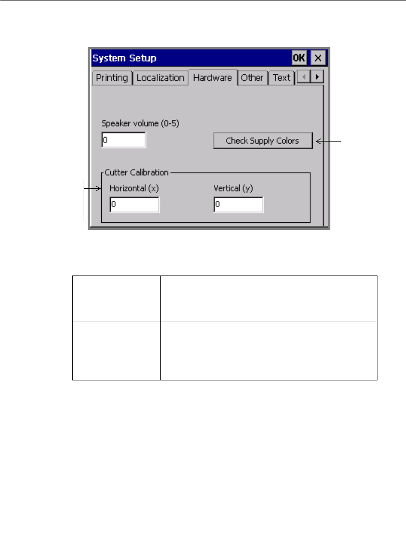
5-8 Setting Hardware Tab Options
Setting Hardware Tab Options
Use the Hardware options tab for settings that affect your system’s hardware.
Figure 5-3. The System Setup Hardware tab.
The options are:
Speaker volume
(0-5)
Controls the volume of your system sounds. Enter a
value from 0-5, where 0 turns your sound off
completely.
Check Supply
Colors
When enabled, tells your system to read the current
supply cell. If there are any missing color names,
the system prompts you to supply them. See
Naming supply colors on page 5-9 for instructions.
Cutter Calibration
options appear
only on Color &
Cut system
Unavailable on
the Monocolor
system.
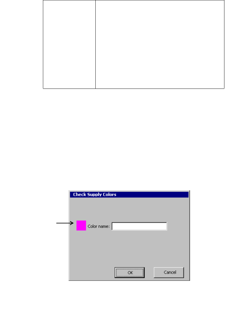
Setting Preferences 5-9
Naming supply colors
When new tape or ribbon supplies become available after your print system is
shipped to you, your system will not have internal information about those new
supplies. The Check Supply Colors button lets you supply the names of new
supplies and store them in your system.
To supply names for new ribbons or tapes
1. Install the new tape or ribbon in your system.
2. Choose the Check Supply Colors button on the Hardware options tab.
The Check Supply Colors screen displays:
Sample of
color to be
named is
shown in the
Multicolor and
Color & Cut
systems only.
Figure 5-4. The Check Supply Colors screen.
Cutter
Calibration:
Horizontal (x)
Vertical (y)
Color & Cut system only. Re-sets the factory-set
calibration values for the plotter cutter in your
system. Enter positive or negative whole numbers
to adjust the horizontal or vertical values by one/one
thousandth of an inch for each increment.
Note: Use caution when calibrating your plotter
cutter. To return to the factory-set values, see the
calibration label placed inside your printer at the
factory, and reinstate the values shown on that label.
See Calibrating the Cutter on page 10-11 for more
information.
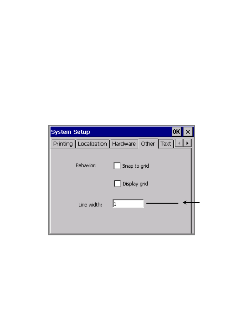
5-10 Setting Other Tab Options
3. Enter a name for the color, up to 32 characters in length. Be sure the name is not
already in use in your system.
4. If you change your mind or make a mistake, press Cancel. To save the name
you typed, choose OK
5. If the system detects additional missing color names, it prompts you again with
the Check Supply Color screen, and repeats the process until you have
supplied names for all new colors.
When all colors are named, the system displays a message.
Setting Other Tab Options
Set default grid preferences and line width using the Other tab, shown here:
Figure 5-5. The System Setup Other tab.
Sample
display of
the Line
Width you
choose
Setting Preferences 5-11
The Other tab options are:
Displaying the screen grid
The screen grid is the pattern or structure that underlies your labels. It consists of
invisible horizontal and vertical lines of dots, arranged like a graph paper pattern.
The grid is not visible to you by default, but you can choose to display it.
Hint! Displaying the grid can help you set objects in precise locations on your
labels, such as when you want to line up several objects, or when you must
place an object in an exact location on your label.
Snap to grid Check this option to make new objects or objects
that you are re-positioning automatically move to
vertical and horizontal alignment on the grid. This
option is OFF by default.
Hint! Snap to grid helps you align objects
precisely.
Display grid Check this to turn the grid lines ON in your display
screen. This option is OFF by default. See
Displaying the screen grid on page 5-11 for more
information.
Hint! Display the grid to help position objects
precisely on your labels.
Line Width Specifies the default line width value for HotShape
objects and label frames. Higher numbers indicate
wider lines. The sample line next to this field
displays the line width as you set it.
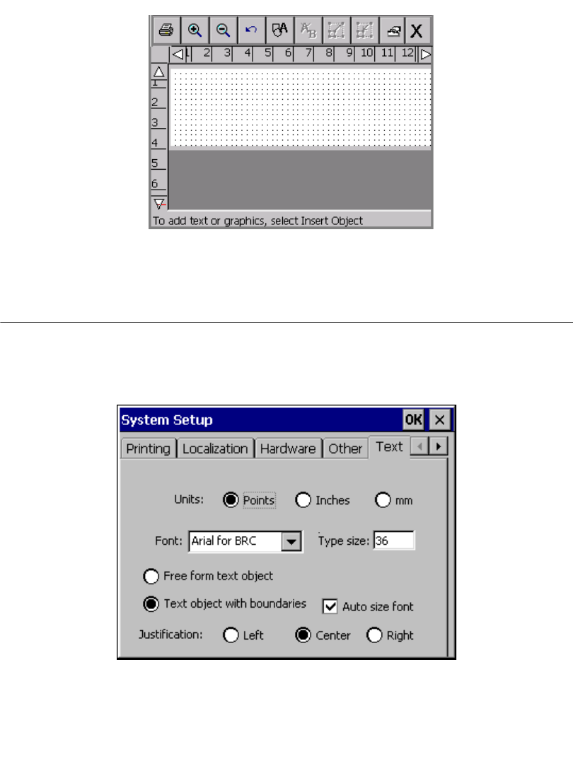
5-12 Setting Text Tab Options
This is a sample screen with the Display grid option turned on:
Figure 5-6. The Editor window with grid enabled.
Setting Text Tab Options
Set the default text preferences for your system by using the options on the Text
tab.
Figure 5-7. The System Setup screen Text tab.
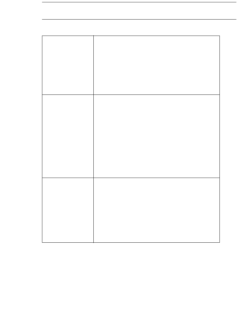
Setting Preferences 5-13
Note: Text tab option changes affect only new text objects you create. These
settings do not affect objects provided by templates or QuickText labels.
The options are:
Units Sets the unit of measure used for the type on your
labels as:
•Points
•Inches
•mm (Millimeters)
The default setting varies by country.
Font Sets the default font style. Pull down the list and
select a font style. The factory-installed fonts are:
•Arial 65 for BRC
•Arial for BRC (default)
•Brush Script for BRC
•Tahoma
•Times New Roman for BRC
Your system may offer additional fonts installed by
your organization.
Type Size Sets the default type size. Enter the size you want to
use as the default. Note that the system default size
of 24 points is based on the largest type size that
will fit on the smallest tape width (.5 inch).
Hint! If you are working exclusively with a
certain tape supply, you may find it useful
to set the Type Size default setting to one
appropriate for that tape width.
5-14 Setting Text Tab Options
Free Form Text
Object
Sets the default for any new free form text object
you create.
Note: To change this setting for an individual text
object, go to the Options tab on the object Tex t
Properties screen. See Setting options on the
Options tab on page 7-40 for details. Changing this
setting on the Options tab will not affect the setting
you have selected here.
Text Object With
Boundaries
Sets the default for any new text object with
boundaries you create.
Note: To change this setting for an individual text
object, go to the Options tab on the object Tex t
Properties screen. See Setting options on the
Options tab on page 7-40 for details. Changing this
setting on the Options tab will not affect the setting
you have selected here.
Auto Size Font Available only when a Text Object With
Boundaries is selected. Sets the default point size
of text to fit within the text object.
Note: To change this setting for an individual text
object, go to the Options tab on the object Tex t
Properties screen. See Setting options on the
Options tab on page 7-40 for details. Changing this
setting on the Options tab will not affect the setting
you have selected here.
Justification Sets the alignment that will be the default for labels
with a single line or with multiple lines within a
single text object.
•Left aligns the text so that each line starts on the
left side of the text object.
•Center aligns the text so that each line is
centered on the text object (default).
•Right aligns the text so that each line ends
against the right side of the text object.
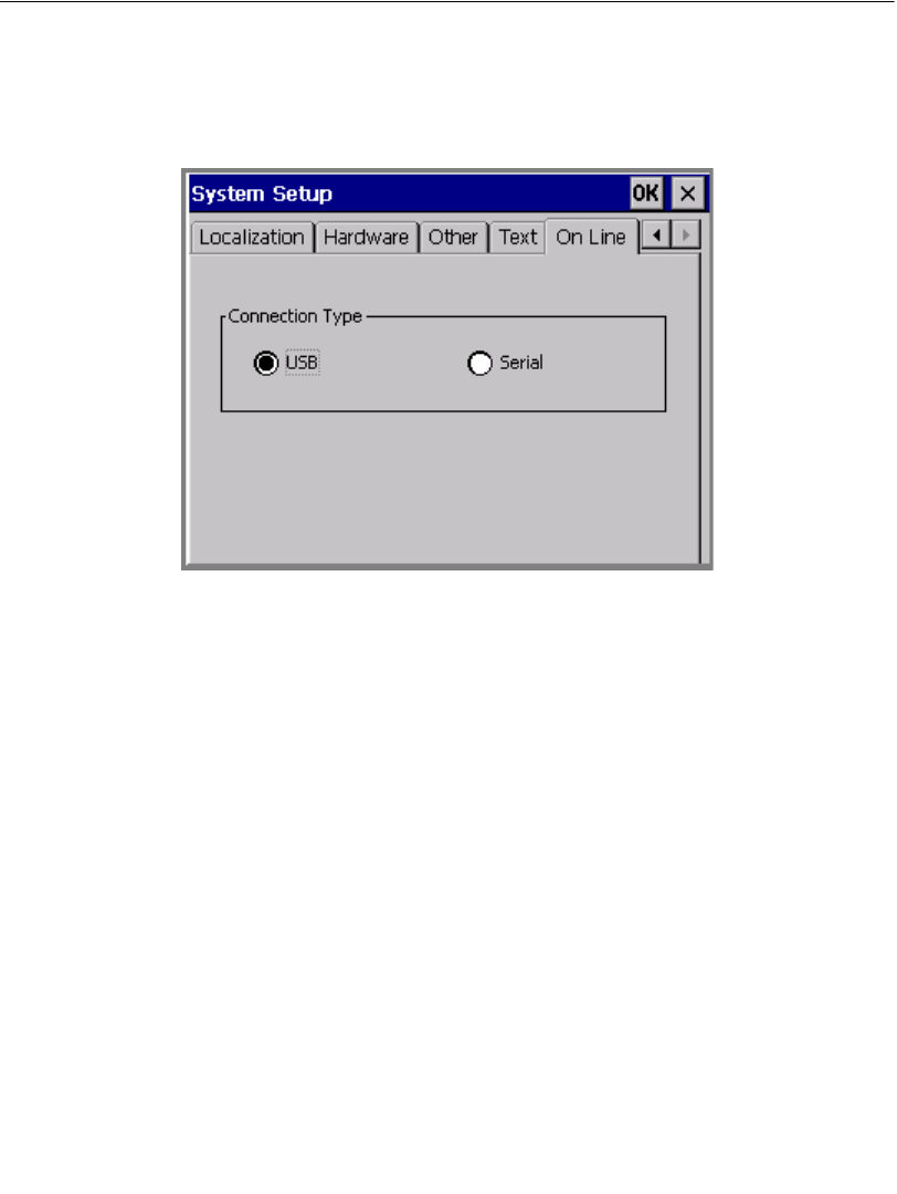
Setting Preferences 5-15
Setting On Line Tab Options
Set the default PC connection type settings for your system by using the On Line
tab option:
Figure 5-8. The System Setup screen On Line tab
The Connection Type option sets the port type to be used when connecting to a
PC. Choose USB or Serial.

5-16 Setting On Line Tab Options

6-1
Working with labels is what your printing system and this manual is really all
about. This chapter describes the most important part of that process: how to create
labels.
You’ll learn how to use the applications this system offers on the Main Menu to
create all kinds of labels. You’ll also learn how to change the physical properties of
your labels, and how to create and use sets of multiple labels to your advantage.
The topics in this chapter are:
Creating Custom Labels
Creating QuickText Labels.
Creating Template Labels.
Creating Sets of Labels
Changing Labels
Setting Application Preferences
CHAPTER 6 Working with Labels
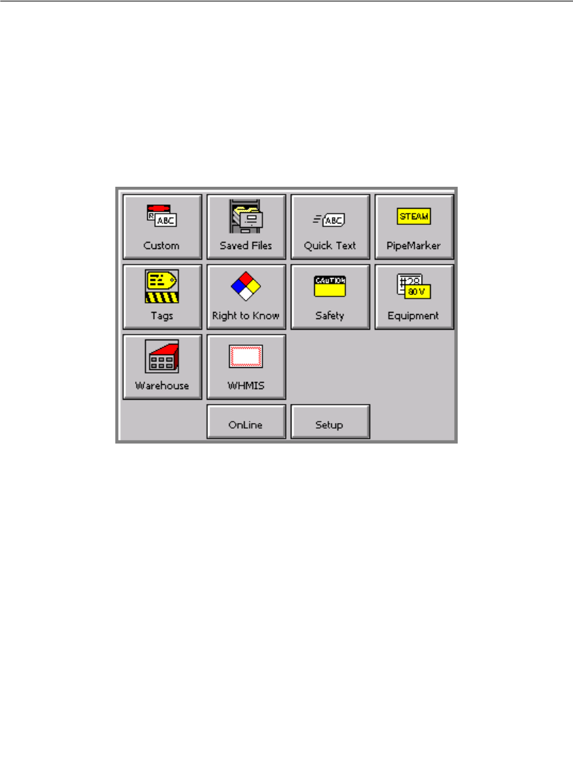
6-2 Creating Custom Labels
Creating Custom Labels
This procedure shows you how to use the Custom application to create labels that
you design, without using pre-designed layouts.
You will find information about using pre-designed layouts, called templates, in
Creating Template Labelsn page 6-10.
To create a Custom label
1. From the Main Menu screen, as shown here, choose Custom.
Figure 6-1. The Main Menu screen
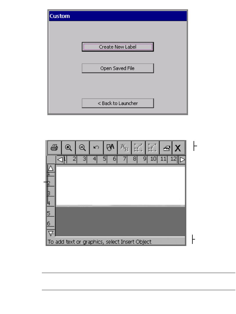
Working with Labels 6-3
2. On the Custom screen, shown here, choose Create New Label:
Figure 6-2. The Custom screen.
You’ll see the Editor window:
Toolbar
Preview
area, which
displays your
work as you
create a
label.
Status bar
Figure 6-3. The Editor window.
The Editor window is ready to display the label as you create it.
Hint! The most typical next step in creating a label would be to add an object.
See Working with Objects for instructions.
6-4 Creating Custom Labels
At this point, the system operates with these defaults:
zThe blank label displayed reflects the size and color of the tape installed. If no
supply is installed when you launch Custom, the system assumes you are using
a white, 4-inch (102 mm) wide tape.
zThe ribbon installed in your printer determines your color choices for the
objects you insert on your labels. If no ribbon is installed, the system assumes a
black continuous ribbon. See About Color on page 8-2 for more information.
Hint! For best print results and greatest ease-of-use, before you create a label,
install the supplies you want to use to print it. The system then
automatically adjusts label length and offers you the appropriate color
choices.
zThe blank label displays with landscape print orientation assumed.
zThe magnification (or zoom level) is set to display 12 inches of label length, but
this does not reflect the actual printable length of the label. The objects you add
to the label determine the final length of the label, or, if you have a paneled
ribbon installed, the length of the panel determines the maximum length of the
label. See Checking Length on page 11-12 for more information.
Hint! To control the length of your label, set the length before adding objects.
Use the Set Length option on the Size tab of the Label Properties screen.
From inside the Editor window, you can:
zAdd text, graphics, HotShapes, or bar codes to your label. See Working with
Objectsn page 7-1 for instructions.
zEdit or change the properties of the objects you added to your label. See
Changing Objectsn page 7-31 for instructions.
zPrint your completed label. See Printingn page 11-1.
zSave your label as a file so you can access it later. See Working with Files on
page 9-1 for instructions.
Hint! Be sure to browse through the standardized label designs, called
templates, on your system. You may find a pre-designed label that meets
your needs. See Creating Template Labelsn page 6-10 for information
about these easy-to-create labels.
Also see Inside the Editor windown page 4-3 for more information about
working in the Editor window.

Working with Labels 6-5
Creating QuickText Labels
QuickText helps you create plain text labels very quickly. When you choose
QuickText on the Main Menu screen (Figure 6-1), all you have to do to create a
label is enter your text.
QuickText supports only a single text object on a single label. The system
automatically creates the text object when you type the text.
The system automatically:
zSizes the printable area equal to the tape you have installed.
zDetermines the text color by the installed ribbon. You may not use the Reverse
text color option (described in Setting options on the Options tabn page 7-
40).
zSizes the text you type to fit the width of the label.
zDetermines the label length based on the text you enter. You may not change the
length.
zAssumes the print orientation.
zDisplays the entire label for you to print or edit.
zSets the label for printing only. If you have the Color & Cut system, you may
not use the Cut feature with a QuickText label.
zIf no tape or ribbon is installed, assumes you are using the default supplies: a
white four-inch tape and a black ribbon.
See About Objectsn page 7-2 for definitions and descriptions of objects.
Note: QuickText is designed for printing simple labels only, and does not
support some of the features this printing system offers. If you anticipate adding
objects like graphics or HotShapes to your label, build it using the Custom
application, as described in Creating Custom Labelsn page 6-2.
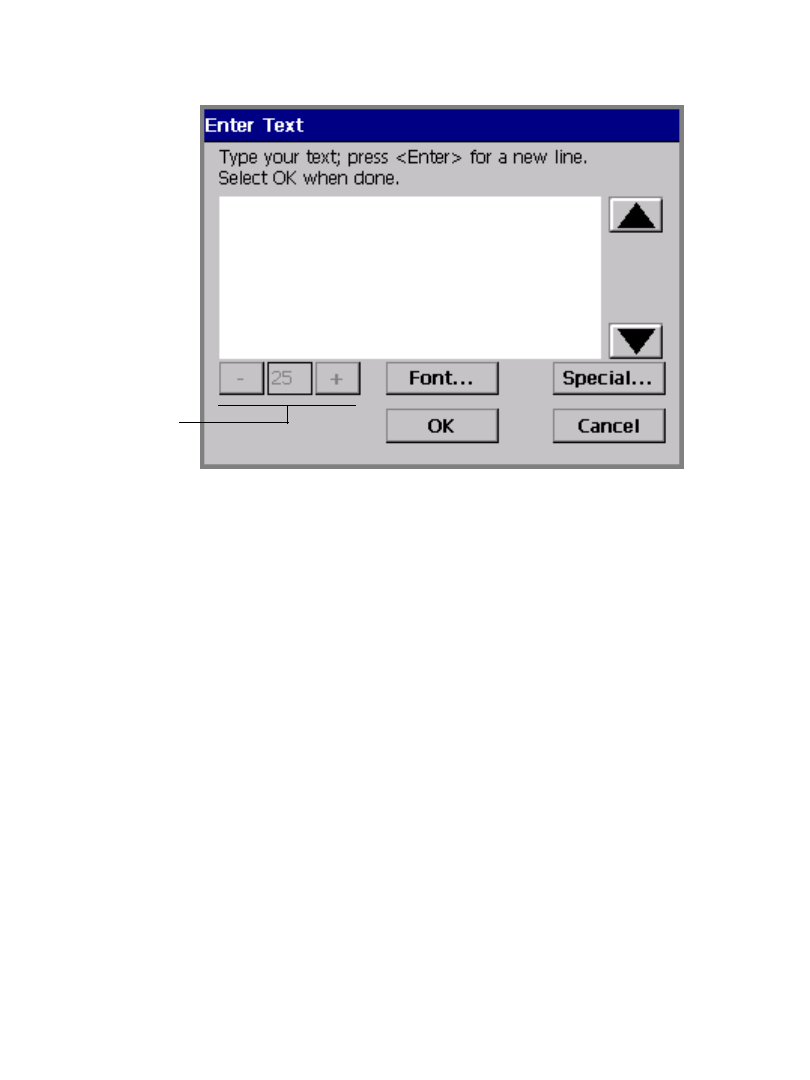
6-6 Creating QuickText Labels
To create a QuickText label
1. Choose QuickText from the Main Menu screen (Figure 6-1).
You’ll see the Enter Text screen:
Option disabled
because QuickText
automatically
calculates type size
Figure 6-4. The QuickText Enter Text screen.
2. Follow the on-screen instructions and type your text. You can change the font or
add special characters at any time on this screen, but you cannot change the
Type size on this screen. This is because after you type your text, the system
automatically calculates a type size for you, based on the number of lines you
typed and the width of the installed tape.
3. When the text is complete, select OK. (If you select Cancel at this point, the
text you entered is erased and you’ll be returned to the Main Menu screen.)
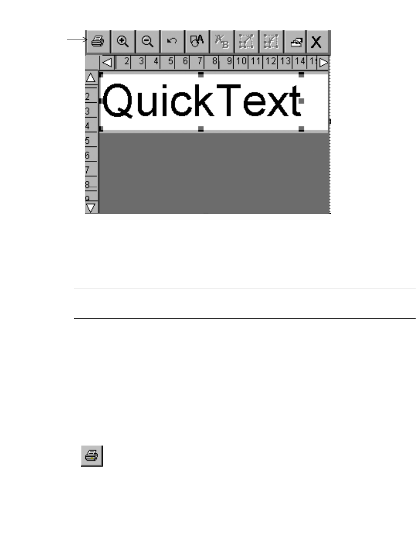
Working with Labels 6-7
QuickText formats your label and displays it on the QuickText version of the
Editor window:
QuickText
toolbar
[
Figure 6-5. The QuickText Editor window.
Once the label shows in the Editor window, you can either print it as is, or edit the
text. (See Opening and editing an objectn page 7-31 for instructions for editing
text objects.)
Note: You may not use Object Properties to change the text object in
QuickText labels.
You can save QuickText labels as files, and you can retrieve them, just as you save
and retrieve other labels in this system. See Saving Labels as Filesn page 9-3 for
more information.
QuickText toolbar functions
QuickText offers a subset of the tools you normally see on the Editor window
toolbar (shown in Figure 6-5). Use the QuickText tools to perform these functions:
Print. Prints the label. Choose and then follow the instructions on the
Print screen. Advanced functions are not available in QuickText. See
Printingn page 11-1 for details.
6-8 Creating QuickText Labels
Zoom In. Increases the magnification, making the objects on the label
look larger. Does not change the actual size of the printed label, but is used
as a viewing aid. See Zooming in and zooming outn page 4-6 for details.
Zoom Out. Decreases the magnification, making the objects on the label
look smaller. Does not change the actual size of the printed label, but is
used as a viewing aid. See Zooming in and zooming outn page 4-6 for
details.
Undo. Reverses the last action you performed, when possible. When
actions may not be undone, the Undo button is grayed out.
Insert Object. Allows you to select the type of object you want to insert in
the label, such as text, graphic, bar code, and so on. See Adding Objectsn
page 7-3 for details.
Edit Object. Allows you to edit the object selected, depending on the type
of object. For example, for text, you’ll see the text editing screen. For
graphics, you’ll see the graphics selection prompt. See Opening and
editing an objectn page 7-31 for details.
Increase Size. Increases the size of the selected text or graphic. The text or
graphic remains in its original proportions, but displays and will print 10%
larger for each time you press the Increase Size button. See Using
Increase Size and Decrease Sizen page 7-28 for details
Decrease Size. Decreases the size of the selected text or graphic. The text
or graphic remains in its original proportions, but displays and will print
10% smaller for each time you press the Increase Size button. See Using
Increase Size and Decrease Sizen page 7-28 for details.
Properties Menu. Displays different options that apply to the object
selected including: Color, Object Properties, Move to Back, and Move to
Front.
Color. Lets you choose color for the selected object or change the default
color the system uses for drawing new objects. See See CHAPTER 8:
Applying Color, beginning on page 8-1 for details.
Object Properties. Lists information about the object selected, which can
be either text or graphic, including height, width, rotation, and so on. This
button is valid only when a single object is selected. See Changing object
propertiesn page 7-32 for details.
Working with Labels 6-9
Move to Back. Moves the selected object to the back of any layered
objects, so that the other objects obscure or cover up the selected object.
Move to Front. Moves the selected object to the front of any layered
objects, so that the selected object obscures or covers up any objects
behind it.
Exit. Returns to the Main Launcher screen.
Hint! Press Shift along with Decrease type size or Increase type size to change
the type size in larger increments.
QuickText key functions
Not all system function keys are operative in the QuickText application, either
because the functions are irrelevant, or because of limitations on the design and
functions of QuickText labels.
Available key functions are:
zAdvance & Shear
zEdit Data (edits text object)
zHelp
zStatus
zClear
zUndo
zEdit Object (edits text object)
zObject Color
zMenu
zFile Options
zPrint (not including Advanced features)
See System function keysn page 3-5 for more information about the key
functions.

6-10Creating Template Labels
Creating Template Labels
Your label printing system provides many templates you’ll find useful for creating
standardized labels. Templates are pre-designed specialty layouts you use to set up
and format a standard label.
Creating labels using these layouts is particularly easy. Once you have chosen a
label group, which is called an application, (shown in Choosing a label
applicationn page 6-11) and the template category (shown in Choosing a
categoryn page 6-12) for the label you want to create, you simply respond to the
on-screen prompts the system displays as it takes you through choosing graphics,
adding text, setting dimensions, or a combination of all of these processes.
The basic process for creating labels using templates is very similar for all
applications and templates:
Step 1: You choose a label application.
Step 2: You choose a category.
Step 3: You choose a template from the category.
Step 4: You respond to prompts that add text or graphic objects to the label as the template
requires. The prompts are numbered so you can track your progress as you go
through the process.
Step 5: You print or save your label.
Some label types require more steps and involve more prompt screens than others,
but the general process is comparable.
The following sections take you through a generic example, to give you a basic
understanding of the process.
Note: You’ll be able to edit some of the objects on some of the templates to meet
your own label requirements. Some objects and some templates are designed to
meet established stock or regulatory requirements, however, and may not be edited.

Working with Labels 6-11
Pipe Marker and Right-to-Know exceptions
The Pipe Marker and Right-to-Know applications contain highly specialized
templates created for special situations. Most of you who use these applications are
already familiar with the standards and requirements for these types of labels.
When you create Pipe Marker and Right-to-Know labels, you follow the general
steps listed above, but you will encounter more exceptions to the generic examples
with these applications than with other applications.
For the most part, you will be able to create Pipe Marker and Right-to-Know labels
easily by simply following the prompts on the display screen. When the exceptions
to this process are significant, we’ll provide special instructions. Watch for this
designation:
Exception: This note contains special information about the Pipe Marker or
Right-to-Know applications.
Choosing a label application
The templates are organized in groups of similar designs, called applications,
which are listed on the system’s Main Menu screen (as seen in Figure 6-1 on
page 6-2). With the exception of the Custom application and the QuickText
application, each application contains one or more categories of pre-designed
templates, and are referred to as template-based applications.
All template-based applications use pre-designed layouts supplied with your
system. (See The Main Menun page 3-2 for full descriptions of all applications.)
Hint! You can set default application preferences (similar to system settings) for
each application, though the settings you may change vary according to
the application. See Setting Application Preferencesn page 6-33.
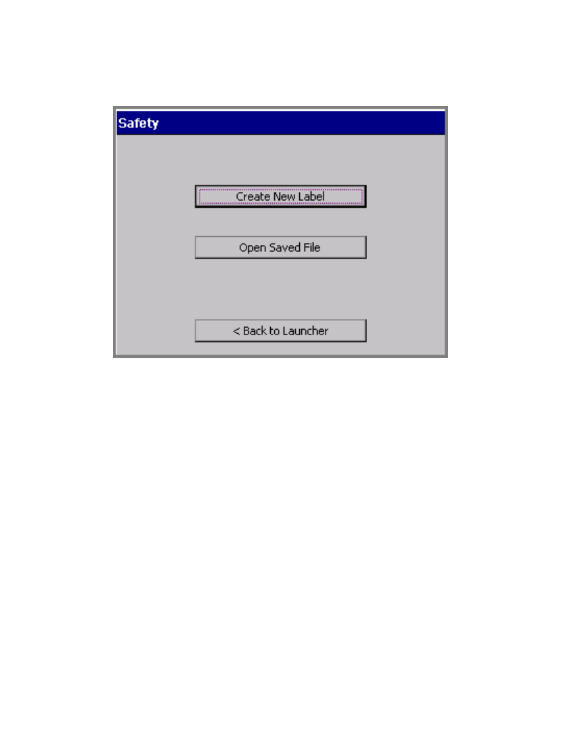
6-12Creating Template Labels
To choose an application
1. On the Main Menu screen (Figure 6-1), select the application for the label you
want to create.
You’ll see a version of the Create or Open screen, such as the Safety application
version shown here:
Figure 6-6. The Create or Open screen, Safety application.
You’ll encounter a version of this screen every time you start an application.
The screen title varies according to the application chosen, but the options are
the same each time you create a new label.
2. Choose Create New Label. Next, you’ll be prompted to choose a template
category.
Choosing a category
Each application offers a choice of categories as the first step in creating a label.
The categories listed on the template categories screens each offer a group of
related templates.
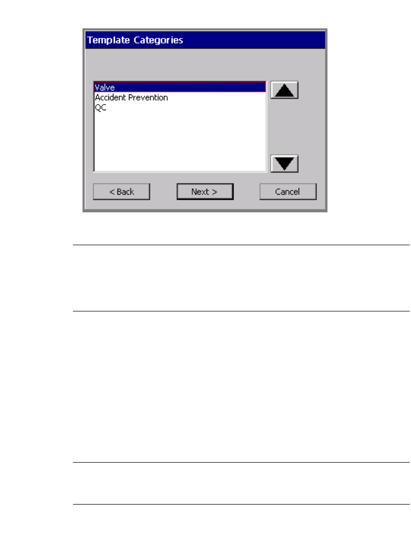
Working with Labels 6-13
The Template Categories screen is very similar for most applications, but the list
of categories varies:.
Figure 6-7. The Template Categories screen, Tags application.
Exception: Pipe Marker next lists styles on the Pipe Marker Style screen.
Right-to-Know next lists formats on the Right-To-Know Format screen.
Both Pipe Marker and Right-to-Know also provide the Preferences option on
these screens. See Setting Application Preferencesn page 6-33 for information.
To choose a template category
1. On the Template Categories (or similar) screen, choose a category from the
list.
2. Choose Next to proceed to the next prompt screen.
For most applications, next you’ll see the Select Template screen.
Selecting a template
Exception: In Pipe Marker and Right-to-Know skip this step and proceed
directly to prompting you for setting label dimensions. You select a template on a
previous screen.
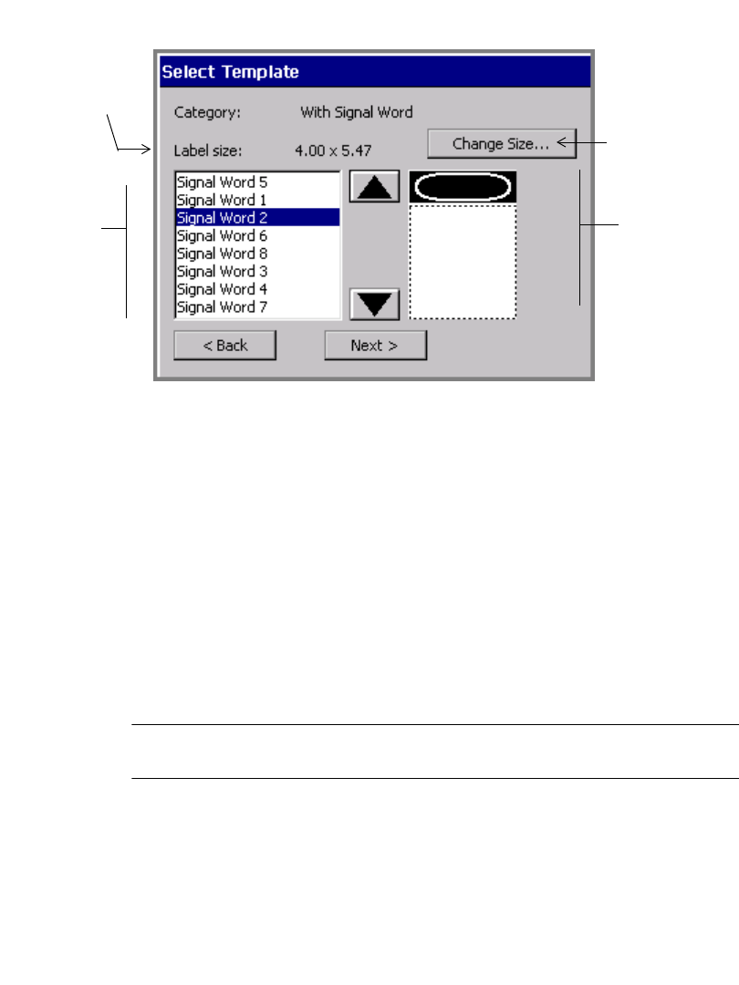
6-14Creating Template Labels
Each template listed on the Select Template screen represents a pre-designed
layout.
Figure 6-8. The Select Template screen
The content of the Select Template screen depends on the type of label you are
creating.
zThe Category field reflects the category chosen in the previous screen.
zThe Label size field displays the default size for the template currently
highlighted. This reflects the total output size of the final label, with no changes
applied. The label size is determined by the template you select, however. For
instance, for a scalable-label template, the Label size field is determined in part
by the installed tape size -- the template sets the label to be sized as large as will
fit on the installed tape. Some templates call for preset-size labels, and some
templates produce a fixed-size label only. In both cases, you may not change the
label size. In those cases, the Change Size button is grayed out on the Select
Template screen.
Hint! Some preset labels may also be set to turn on the Supply saver option for
printing. See Supply saver optionn page 11-21 for information.
zThe Change Size button may or may not be enabled, according to the template
chosen.
zThe list of templates provides a miniature graphic representation (called a
“thumbnail”) for the highlighted template. This feature may help you choose
the appropriate template for your purpose. In the template shown in Figure 6-8,
Thumbnail
representation
of the selected
template
List of
templates
Disabled for
fixed-size
templates
Label size
shows the
output size of
the label with
default
settings
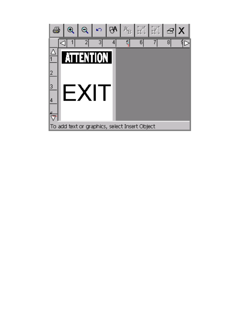
Working with Labels 6-15
for instance, you’ll be prompted to add a graphic sign header (or signal word) to
the top part of the label, and a text object to the bottom part. Using the template
shown in Figure 6-8 above, you could create a label that looks like this:
Figure 6-9. Sample Signal Word label.
To select a template
1. Choose a template from the template list by highlighting it.
2. Next, you have two choices:
•Click Next for the next prompt in the sequence, and go to the Following
prompt sequences section below for further instructions.
or
• Choose Change Size to change the label size, as described in the Changing
Labelsn page 6-24.
6-16Creating Template Labels
Following prompt sequences
Each label type that uses pre-designed layouts has prompt sequences unique to its
type. These prompts are designed specifically to help you create the content of your
label.
Depending on the application and template you are using and the label you are
creating, you may be prompted for one or more of the items listed below. You may
even be prompted for multiple instances of the same one of these items:
zText entries
zText list entries
zGraphic objects
zBar codes
Exception: See Responding to Pipe Marker promptsn page 6-19 and
Responding to Right-to-Know promptsn page 6-20 for other prompt screens you
may encounter when working with the Pipe Marker and Right-to-Know
applications.
During the prompt sequence, you may have these options:
zBack to go back to the previous screen
zBack to Launcher to return to the Main Menu screen.
zCancel to interrupt the prompt sequence. You’ll see the label in the Editor
window. None of your prompt responses are saved.
zNext to proceed to the next prompt.
zFinish on the final prompt screen in the sequence. When you choose Finish, the
label you created is displayed in its final form in the Editor window.
Hint! If you want to go back and rerun an entire prompt sequence to edit the data
you entered, use the <Edit Data> key. See Changing Labelsn page 6-24
for complete information.
Since you will be prompted for information each step of the way, we’re confident
that you’ll find each process simple and straightforward. To help accustom you to
the process, however, the sections that follow take you through some generic
prompt sequences.
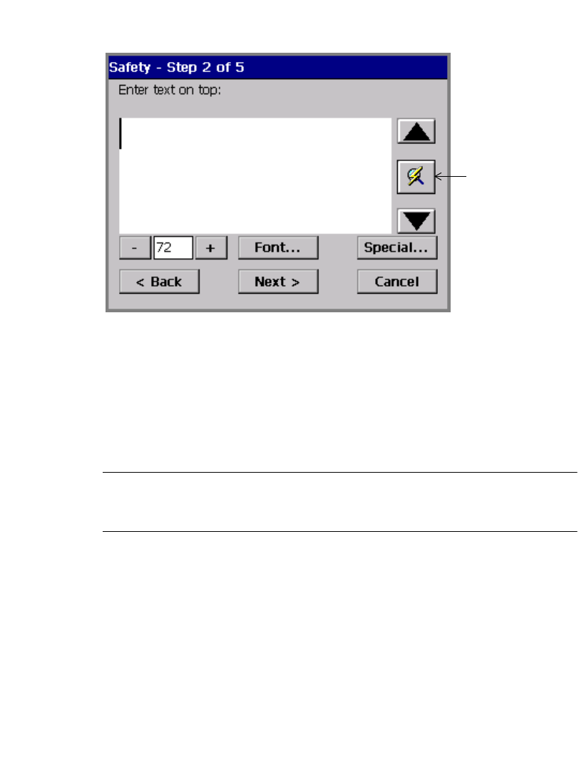
Working with Labels 6-17
Responding to text prompts
Figure 6-10 shows a generic version of a text prompt screen:
Figure 6-10. A text prompt screen.
You’ll see a similar text entry prompt screen when you are working with a template
that requires you to enter your own text. (You see a similar text entry screen when
you create a text object using the Custom application and when you create a
QuickText label.)
Some templates require that you enter specific text: for example, the prompt may
instruct you to “Enter product identifier” or to “Enter risk phrases.”
Note: Space limitations make it unable to document all possible responses to
these prompts. If you are using templates with this kind of specialized request, we
assume you understand the requirements.
Complete this screen as you would any text entry area, by typing in the appropriate
text. (See Adding and formatting text objectsn page 7-4 for complete
instructions.)
Refresh Screen
button. Use if the
size of the text
entered exceeds
the text entry
window.
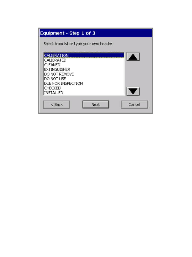
6-18Creating Template Labels
Responding to pick list prompts
When the template you are using calls for a certain type of word or phrase, you may
see a pick list prompt screen from which you can choose the appropriate word or
phrase:
Figure 6-11. A pick list prompt screen.
You can choose text and you can also go on to create your own word or phrase
from this screen. When you choose Next, you have the option to enter your own
text phrases.
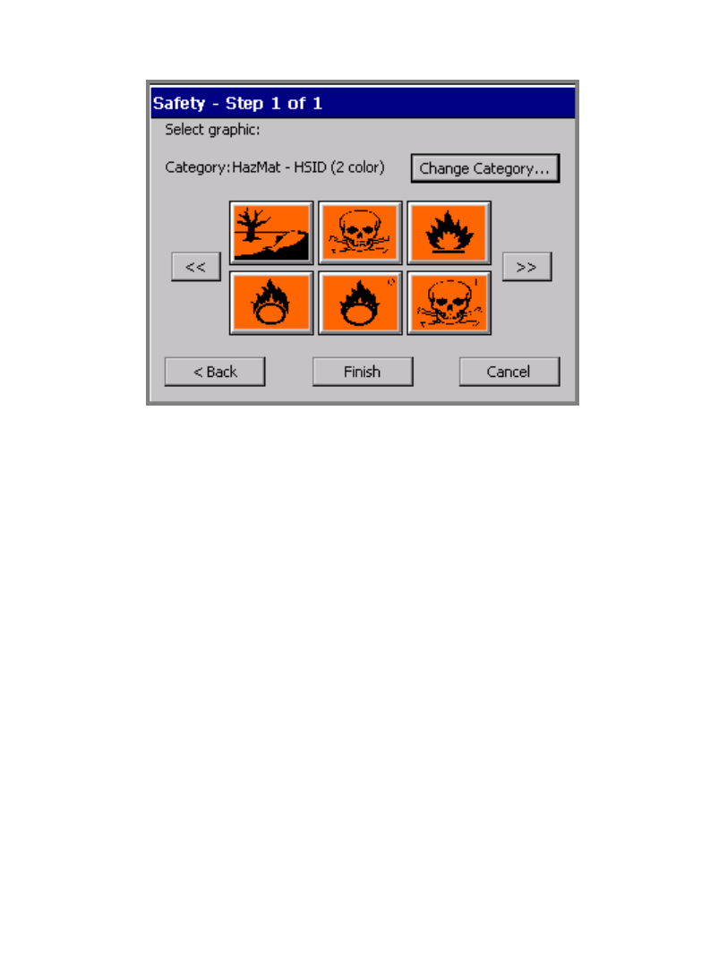
Working with Labels 6-19
Responding to graphics prompts
Figure 6-12 shows a graphics prompt. For this template sequence, you are being
prompted to choose a HazMat graphic:
Figure 6-12. A graphics prompt screen.
Complete this screen by choosing a graphic from the thumbnails displayed. You
can also:
zUse the scroll arrow keys to view additional thumbnails.
zUse the Change Category option to go to the Graphic Categories screen (for
an example, see Figure 7-14 on page 7-22), where you can open another
category and see more graphics.
Responding to Pipe Marker prompts
A typical Pipe Marker application template prompt sequence includes some or all
of these prompt screens:
zPipe Marker Style, where you choose the type of Pipe Marker you want to
create: standard, rollform, or symbol or arrow tape
zDimensions, where you select width, length, and height for your Pipe Marker
label
zPipe Contents, where you choose the contents that describe the pipe you are
marking
zLegend, where you enter legend lines and supplemental data for Pipe Marker
labels

6-20Creating Template Labels
zGraphics, where you choose one or more graphics from various categories to
apply to your Pipe Marker labels
zArrows, where you may specify arrow directions for Pipe Marker labels. This
feature differs for North American and European standards.
zSymbol Type, where you choose symbols for Pipe Marker labels
Responding to Right-to-Know prompts
A typical Right-to-Know application template prompt sequence includes some or
all of these prompt screens:
zRight-to-Know Format, where you choose the type of Right-to-Know label
you want to create
zLabel Size, where you select from label sizes available for the format you chose
zChemical Name, where you enter information about the chemical you are
labelling
zHealth Hazards, where you select a health hazard rating if applicable
zSignal Word, where you select an OSHA- signal word for the label if
applicable
zFire Hazard, where you select a fire hazard rating if applicable
zReactivity, where you select a reactivity rating if applicable
zSpecific Hazard, where you select a hazard rating if applicable
zPhysical and Health Hazards, where you choose the appropriate hazards for
the chemical you are labelling if applicable
zTemperature, when a temperature must be indicated on the label
zTarget Organs, which lists the available target organs for the chemical, where
you select appropriate target organs
zStatement of Hazards, where you type text stating hazards when applicable
zPrecautionary Statements, where you type text specifying precautions when
applicable
zEffects of Overexposure, where you type text describing the condition when
applicable
zFirst Aid Procedures, where you type text providing first aid information
when applicable
zColor Bar and NFPA Manufacturer, where you designate protective
equipment codes and manufacturers.
zComments, where you can add relevant comments to your label

Working with Labels 6-21
Creating Sets of Labels
When you know in advance that you want to print a group of labels all at the same
time, you can create the labels as a set. Sets of labels can save you time, such as
when you don’t want to supervise a long print job, or when you need to print a
number of labels with similar characteristics that won’t require changing supplies.
Hint! For best results, before you compose the labels in the set, install the
supplies you plan to use to print the label set.
As you add labels to the set, the system records the number of each label in
sequence, calculates the total number of labels in the set, and notes it all in the
status bar at the bottom of the display screen. You can view all the labels in the set
by using the Next Label and Previous Label keys.
For best results, before you create a set of labels, make sure the labels meet these
assumptions and requirements. When you create a set of labels, the system:
zAssumes you intend to print all labels in the set at the same time.
zAssumes you intend to create all labels in the set using the same method and
color settings.
zPrompts you at print time for ribbon changes, if you changed colors during the
label creation process.
Note: You may not create sets of labels with labels containing variable text
objects. (For more information, see Adding variable text objectsn page 7-10).

6-22Creating Sets of Labels
Adding labels to a label set
You create labels individually when you are making a set, but after the initial label,
you use the Add Label function to create the next label. The system then assumes
you are making a set of labels and adjusts the process accordingly, with some
differences for custom-created labels and those you create using pre-designed
templates.
Adding custom labels
To create a set of custom labels
1. Create the first label in the set.
2. When it is complete and displayed in the Editor window, press <Add Label>.
You do not have to close the initial label first or do anything to save it. The
system automatically stores it in a temporary location.
Note: The label is saved only temporarily. If you don’t save it as a file at the end
of the editing session, it will be discarded when you close the Editor window.
You’ll see a new blank label in the Editor window, and the status bar displays
the message:
Label 2 of 2.
3. Repeat the process for as many labels as you need in the set.
4. When the set is complete, choose Print. See Printing labels in a label setn
page 11-6 for further instructions.
Adding template labels
To create a set of standardized template labels
1. Create the first label in the set.
2. When it is complete and displayed in the Editor window, press <Add Label>.
3. You’ll see the Template Categories screen, where you can begin the process
again by selecting a template again. Select the same template or a different on.
4. From this point, you’ll be prompted for the same kind of information the system
prompted you for with the original label. The status bar displays the message:
Label 2 of 2.
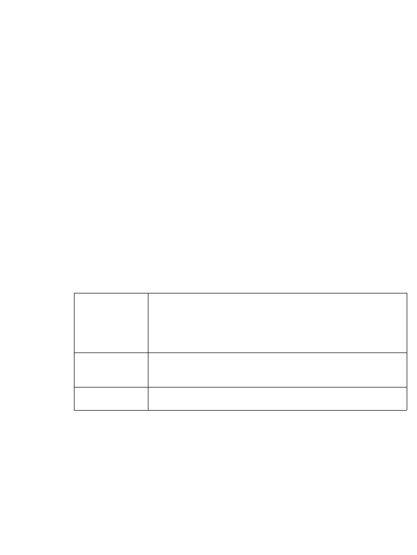
Working with Labels 6-23
5. Repeat the process for as many labels as you need in the set.
6. When the set is complete, choose Print. See Printing labels in a label setn
page 11-6 for further instructions.
Moving between labels in a label set
You can view all labels in a label set sequentially. To move between labels in a set,
press the <Next Label> or <Previous Label> keys. Each label is displayed in turn
in the preview area of the Editor window. The status bar updates with the label’s
number in the sequence and the total number of labels in the group.
Editing labels in a label set
You can edit a label that is part of a set when it is displayed in the Editor window.
Any editing changes you make will affect the current label only.
Clearing labels in a label set
To clear or remove a single label or all labels in the current label set, press the Clear
key. You’ll see the Clear screen, which provides these options:
Clearing Custom labels
When you clear a Custom label, the next label in the set appears. If the label you
cleared is the last one in the set, when you are returned to the Editor window, a
blank label displays.
Clear Current
Label
The system removes the current label in the set, and updates
the data in the status bar. The labels in the set are
renumbered, and the next label in the set displays (with its
new number).
Clear All
Labels
The system removes all labels in the set.
Cancel The last label constructed displays in the Editor window.

6-24Changing Labels
Clearing template labels
When you clear template labels, the next label in the set appears. If the label you
cleared is the last one in the set, the system displays the Template Categories
screen. Then you can either re-start the label creation process, or select Back to
return to the Main menu screen.
Saving label sets
When you save labels you created as a set, the set is saved as a single file. You are
prompted to name that file.
The system then prompts you to save the file in a file group. File groups can
contain one or many label files. It’s important to remember at print time that each
label file can contain a single or multiple labels.
To save a label set
Follow the instructions in Saving Labels as Filesn page 9-3.
Changing Labels
With most applications, you can change the size of a label you create, and you can
edit the objects placed on that label. There are various methods for making
changes, and each method affects different parts of your label.
You can change the size of a label from the Select Template screen during a
prompt sequence.
You can edit template labels either by editing an object or by re-entering the
prompt sequence.
You can change label properties for a single label that include size, orientation,
and framing.
You can set preferences that apply to all labels or, with some application
attributes, for labels are created with a specific application. See Setting
Application Preferences on page 6-33 for information.
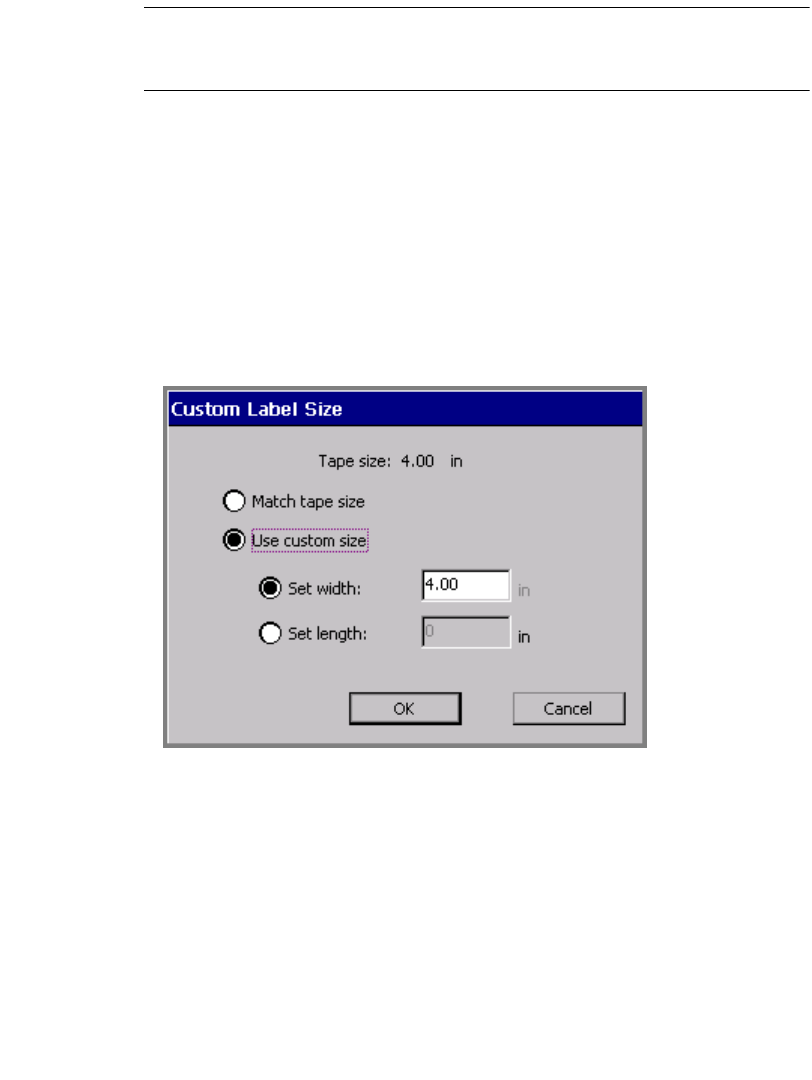
Working with Labels 6-25
Exception: Some Pipe Marker and Right-to-Know application templates do not
allow you to make some changes to labels you create (though sometimes you can
make changes using the <Edit Data> function, which reruns the prompt sequence).
Changing the size of template labels
When the Change Size button is enabled on the Select Template screen (as shown
in Figure 6-8), you may change the size of the label you are creating, even though it
uses a pre-designed template. If the button is disabled, the template you chose does
not allow size changes.
To change the size of a label
1. Choose Change Size. You’ll see the Custom Label Size screen:
Figure 6-13. The Custom Label Size screen.
The value shown in the Set width field matches the currently installed tape.
That is the maximum size label you can create for the tape currently installed,
but you can set lesser width values, or you can set length values on this screen
as well.
2. Choose Match tape size or Use custom size.

6-26Changing Labels
With Match tape size enabled, the system calculates the correct label margins
for the tape currently installed, and updates the Set width and Set length fields
to contain those values
You may not make changes in those fields with Match tape size selected.
•With Use custom size enabled, you can:
Set a custom width. When you choose Set width, the Set length field
becomes unavailable (grayed out).
or
Set the label length. If you choose Set length, the Set width field is
unavailable (grayed out).
3. Once you make changes, choose:
•OK. Note the changed label size.
•Cancel to restore the default label size.
In both cases, you’ll go back to the Select Template screen (Figure 6-8).
4. When you have completed the Select Template screen, choose Next. Even if
you pick a different template than the one selected when you changed size, you
still set a new size.
Editing template labels
Most templates allow you to make changes to the objects placed on a label by the
template. Those templates that do not allow changes will not allow you to perform
the following procedure.
You can edit an object on a template label, or, when you want to make multiple
changes, you can go back through the prompt sequence used to create the label.
To edit an object on a template label
1. After the prompt sequence for creating the label is complete and the label is
displayed in the Editor window, select the object you want to change.
Hint! If the object may not be changed, the system will not allow you to select
the object.
2. Press the <Edit Object> key or choose the Edit Object tool:
The appropriate Graphics screen, Enter Text screen, or whichever
screen is appropriate to the type of object selected appears.

Working with Labels 6-27
3. Make your changes, and choose OK.
Exception: <Edit Object> is not available in the Pipe Marker and Right-to-
Know applications. Use <Edit Data>, which is described below, instead.
For detailed information about editing objects, see Changing Objectsn page 7-31.
You can also make some changes to some template labels using <Label
Properties>. See Changing Label Propertiesn page 6-27.
To re-enter the application prompt sequence
With the label you want to change displayed in the Editor window, press <Edit
Data>. You’ll see the first prompt screen in the prompt sequence you followed to
create the label. Follow the prompts and make the required changes.
Changing Label Properties
The Label Properties screens describe the size, orientation, and framing status of
your current label. You can also use the Label Properties options to:
zChange the size of a label
zChange the print orientation of a label
zAdd a frame to a label
To change label properties
1. Display the label you want to change on the Editor window.
2. Access the Label Properties screen by pressing <Label Properties> on the
keyboard.
3. Choose the appropriate tab screen for the settings you want to change. The
Label Properties screen has two tabs:
•Size, for controlling the dimensions of your labels (Figure 6-14)
•Frame, for adding frames to your labels (Figure 6-16)
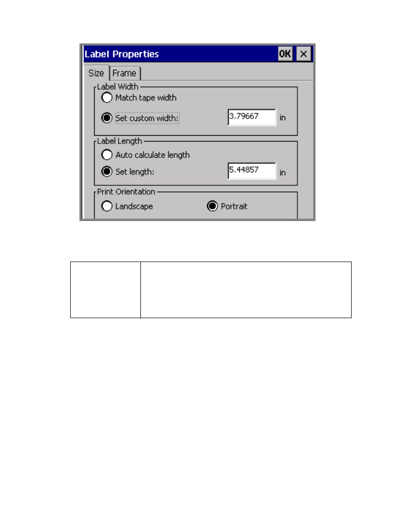
6-28Changing Labels
Changing label size and orientation
Use the options on the Size tab, shown in Figure 6-14, to change the size of a label
and to set print orientation.:
Figure 6-14. The Label Properties screen, Size tab.
The options are:
Match tape
width
Check to set the label size to the maximum that can
be printed on the currently installed tape. When this
option is checked, the Set custom width field is
unavailable (grayed out).
Working with Labels 6-29
Set custom
width
Check this option to set a custom label width. Enter
the new width in the entry field. The value entered
must be less than the maximum printable width
appropriate for the installed tape, because unlike the
default width, this value indicates the total output
width, with no margins applied. This means that the
printable area will equal the amount you specify
here. (See Checking Sizen page 11-11 for more
discussion on this topic.)
With the Monocolor and the Multicolor systems, the
label prints with dashed lines that indicate the
label’s dimensions.
With the Color & Cut system, the label is cut around
its outside dimensions.
Note: Objects previously placed on the label keep
their original size when you resize a label using this
feature. You must manually resize any objects that
no longer fit within the new label size. For
information on resizing objects, see Sizing
Objectsn page 7-27.
This option is not available when Match tape
width is enabled. When Match tape width is
enabled, the value in this field shows the current
width of the label for display only.
Auto calculate
length
Check this option to accept the length the system
automatically sets, based on the contents of the
label. If you have a paneled ribbon installed, the
maximum label length is set to the panel length.
Hint! When this option is enabled, your label
automatically prints with the objects centered on the
length dimension of the label. The system achieves
this by calculating the space between the leading
edge of the label and the first object on the label,
then adding that same amount of space after the last
object on the label.
When this option is selected, the Set length option
is unavailable (grayed out).
6-30Changing Labels
Choose OK when your settings are complete. If your label width is larger than the
printable area of your tape supply, the system displays a message that provides the
maximum size you can use.
Choose Cancel to return to the Editor window without making changes to the
label.
Set length Choose to set your own length for a label, and to
enter the new length in the entry field.
Note: The minimum length label you should print
is 2 inches or 51 mm. If you set a shorter label
length, the printer still delivers a two-inch long
label, unless you are printing in Supply Saver mode.
See Minimum length on page 11-12 for more
information.
When Set Length is selected, the Auto calculate
length option is unavailable (grayed out).
If you have a paneled ribbon installed, you can set
the label length to less than the panel length, but
you may not increase the label length to beyond the
limits of the panel. If you do, the label length
defaults to the panel length.
Landscape Sets the label to print in Landscape mode, where the
height of the label is the width of the tape supply.
This is the default.
Portrait Sets the label to print in Portrait mode, where the
width of the label is the width of the tape supply.
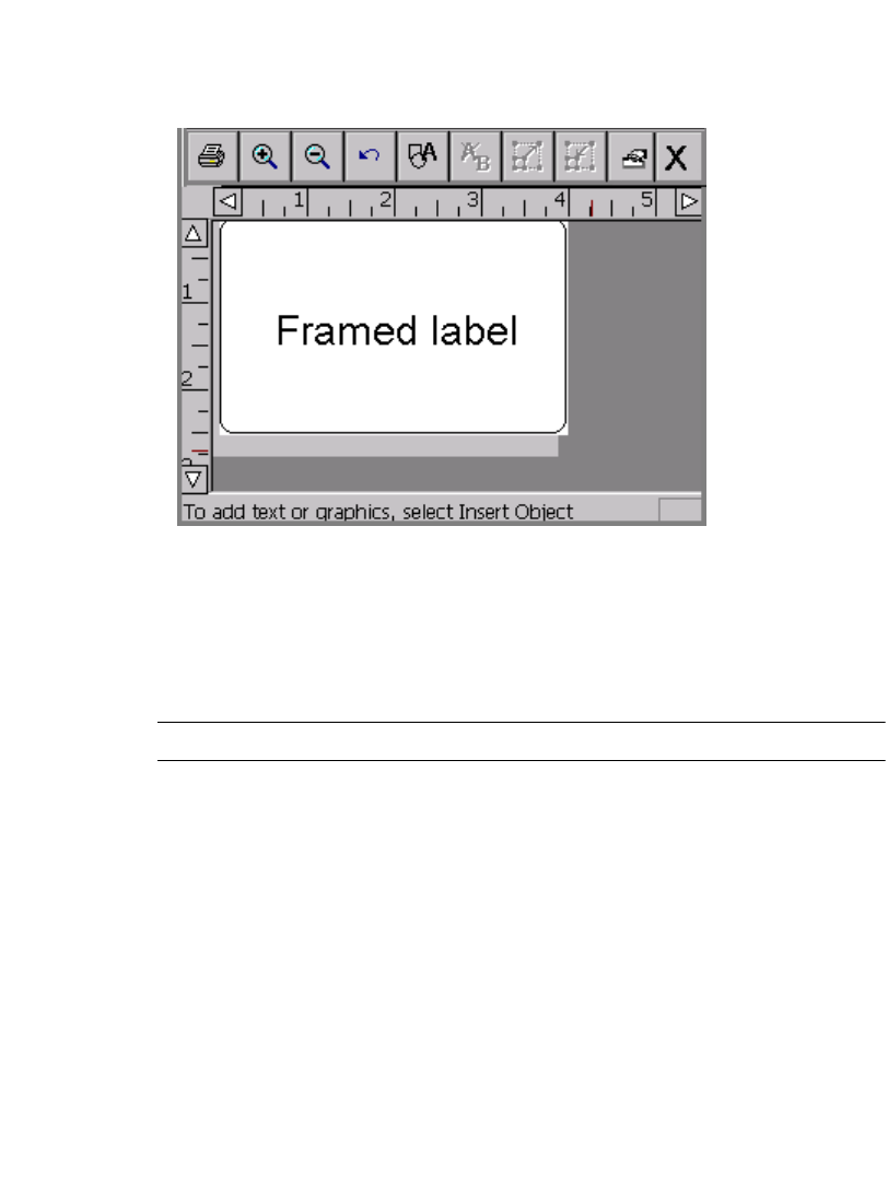
Working with Labels 6-31
Adding a label frame
You can add a frame around the edge of a label in the shape of a rectangle or a
rectangle with rounded corners. This is a sample label with a rounded rectangle
frame added:
Figure 6-15. A sample label with a frame.
You can make the frame line thick or thin, and if you have the Multicolor or Color
& Cut system, you can set a color for the line. If you have the Color & Cut system,
you can also cut out the label around the frame boundaries. See Cutting Around
Label Frames for instructions.
Hint! For best results, create and finish your label before applying a frame.
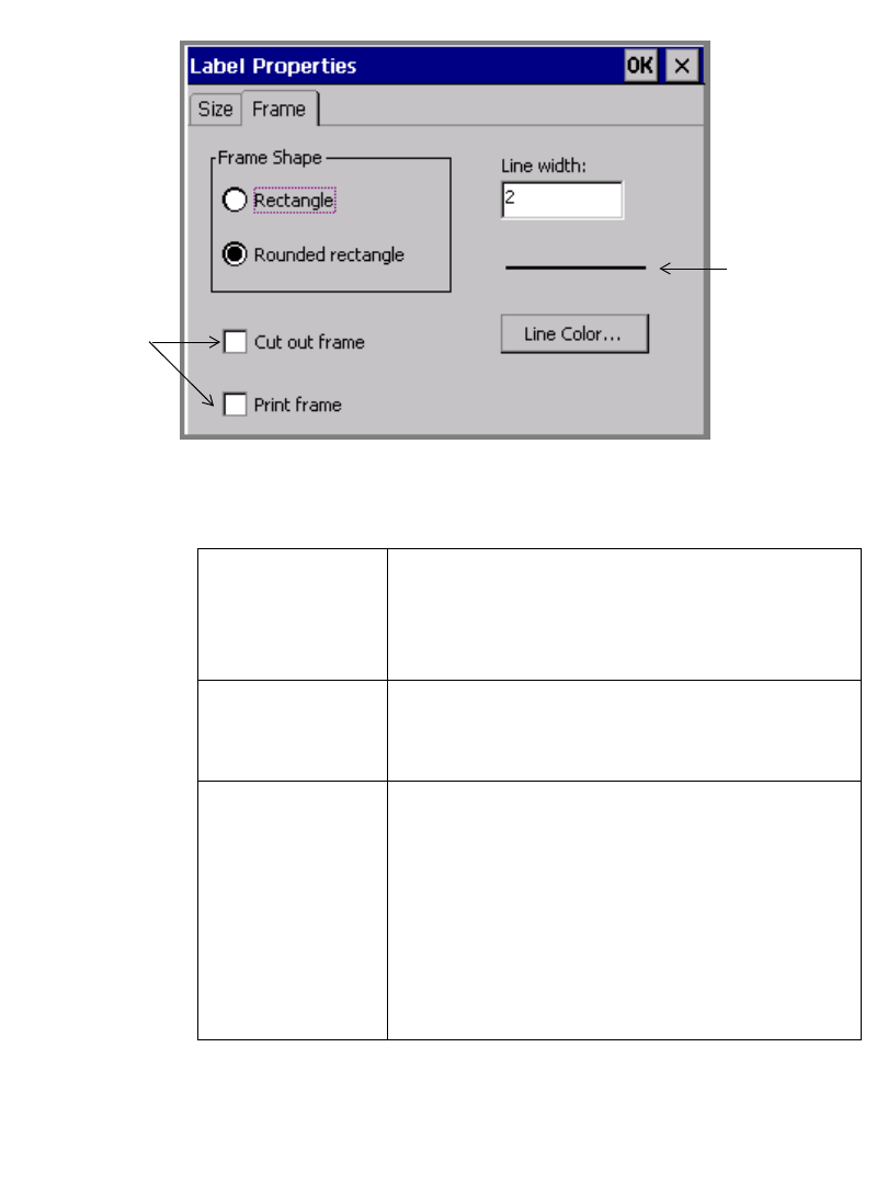
6-32Changing Labels
Use the options on the Label Properties Frame tab to frame a label:
Figure 6-16. The Label Properties screen, Frame tab.
The Frame tab options are:
Frame shape Set to select the shape of the label frame. Choices
are:
zRectangle (default)
zRounded rectangle
Cut out frame If you have the Color & Cut system, check this
option to cut the label along the frame boundary.
This option is not available on the other systems.
Print frame Choose to print the label frame. If you have the
Color & Cut system, you can check both Cut out
frame and Print frame to have the system
automatically size your label to fit within the cut out
boundary.
This option is not available on the Monocolor and
Multicolor systems, where Print frame is the only
choice.
Graphic
representation
of the line
width you set
Visible only on
the Color &
Cut system.
Other systems
automatically
Print
Working with Labels 6-33
Setting frame length
The system uses the length of the label you set in the Label Properties Size screen
to set the length of a frame.
When you do not set a length, leaving it to be automatically calculated by the
system, it sets the frame length according to the data it finds.
If you add or remove objects from the label, the system does not automatically
resize a frame. To resize the frame, you must remove the existing frame and add a
new one.
Setting Application Preferences
Application Preferences settings are very similar to System Setup settings
(described in CHAPTER 5: Setting Preferences, beginning on page 5-1). In some
applications, the Application Preferences screens allow you to set application-
specific preferences that apply to the application only. In most cases, however, the
Application Preferences tabs provide system-wide settings. In fact, several
Line width Use to set a width for the line that composes the
frame. The default is 0, which means no line
appears on the label.
If Cut out frame is enabled, the system ignores the
Line width value.
Line color Use to access the Object Color screen, which lets
you set a line color appropriate for the installed
ribbon. See Applying Color to Objectsn page 8-5.
OK Choose to signal that your settings are complete.
The completed label displays in the Editor window.
If you have set a Line width value greater than 0, a
frame of the shape you selected appears around the
outer edge of the label.
Cancel Choose to return to the Editor window, where the
label displays unchanged.
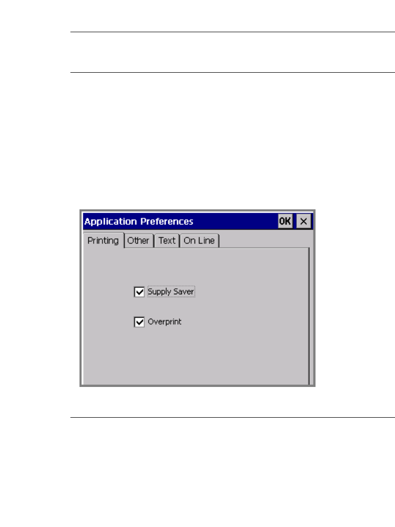
6-34Setting Application Preferences
Application Preferences tabs are identical to those that appear on the System
Setup screen.
Important! When you make a change to Application Preferences or System
Setup options, that change is in effect for all labels you create
from that point on, until you change the settings again.
Some templates, particularly those in the Pipe Marker and Right-to-Know
applications, contain instructions telling them to override preferences you may try
to set. This is to maintain the integrity of the templates, some of which are designed
to comply with federal regulations.
Accessing Application Preferences screens
Press the <Preference> key while inside a label you are creating or one you have
previously created. You’ll see the Application Preferences screen appropriate for
the application in which you are working. This screen can have many tabs, but the
most common configuration is shown here:
Figure 6-17. The Application Preferences screen.
Exception: The Pipe Marker Preference screen offers two tabs: Printing and
Color Norm. The options on the Printing tab apply system-wide. The options on
the Color Norm tab apply only to Pipe Marker labels. See Setting Pipe Marker
preferencesn page 6-35.
The Right to Know Preference screen offers five tabs: Printing, Format, Size,

Working with Labels 6-35
Hazards List, and Organs list. The options on the Printing tab apply system-wide.
The options on the other tabs apply only to Right-to-Know labels. See Setting
Right-to-Know preferences on page 6-36.
Note that the Application Preferences screen Printing, Other, Te xt, and On Line
tabs offer the same options as the System Setup screen tabs of the same names.
These are provided from within applications as well for your convenience, so that
you can change the settings without having to close the application and return to the
Main Menu to access Setup.
Hint! The options on the Printing, Other, Text, and On Line tabs work exactly
the same whether you choose them from Application Preferences or from
System Setup. The settings apply system-wide and remain until you
change them again.
Setting Print tab preferences
The Print tab Preference options are fully described in Printing Tab Optionsn
page 11-19.
Setting Other tab preferences
The Other tab Preference options are fully described in Setting Other Tab
Optionsn page 5-10.
Setting Text tab preferences
The Tex t tab Preference options are fully described in Setting Text Tab Optionsn
page 5-12.
Setting On Line tab preferences
The On Line tab Preference options are fully described in Setting Other Tab
Optionsn page 5-10. Also see Placing Your System Onlinen page 12-4 for
instructions for using these options.
Setting Pipe Marker preferences
The Pipe Marker Preference tabs are:
Printing, which contains the same options as described in Printing Tab Optionsn
page 11-19.

6-36Setting Application Preferences
Color Norm, where you choose the appropriate color norm setting for your country
and language. Your choices vary according to your location and your organization.
For example, your choices in North America are:
zANSI/ASME (USA)
zCAN/CGSB (CANADA)
zAS1345-1995 (Australia/NZ)
Setting Right-to-Know preferences
The Right-to-Know Preference tabs are:
Printing, which contains the same options as described in Printing Tab Optionsn
page 11-19.
Format, where you set the default format for subsequent Right-to-Know label files
you create.
Size, where you select the default size for the default format chosen.
Hazards List, which lists possible physical and health hazards. You add hazards or
delete them from the list. The resulting list displays on the Physical and Health
Hazards screen for all subsequent Right-to-Know labels.
Organs List, which lists possible target organs.You add organs or delete them
from the list. The resulting list displays on the Target Organs screen for all
subsequent Right-to-Know labels.
Note: In the Hazards List tab and in the Organs List tab, changes you make in
one language do not affect the listed hazards when viewed in a different language.
You must edit these lists in each language you intend to use on your Right-to-Know
labels.

7-1
When you create a label, you build it by adding objects to it. Objects can include
text, variable text, graphics, bar codes, and HotShapes.
This chapter describes how to add objects to your labels and how to format them.
Topics in this chapter include:
About Objects
Adding Objects
Selecting Objects
Moving Objects
Sizing Objects
Copying and Pasting Objects
Changing Objects
CHAPTER 7 Working with Objects

7-2 About Objects
About Objects
Before you begin this chapter, it’s important to understand the term objects.
When you create a label, you build it by creating or adding objects to it. The
objects can be made either for printing or for cutting out (if you have the Color &
Cut system).
It may be useful to think of objects as “containers” that can hold various types of
content or data. You decide where to put an object and what to put in the container
when you create your labels. Once you have “filled” an object, it is named for its
contents, so it is called a text object, a graphic object, a bar code object, and so on.
The object types you can add to labels in this system are:
zText objects
zVariable text objects
zGraphic objects
zBar code objects
zHotShape objects
A single label can include multiple objects, such as graphics and variable text, or
text and bar codes. (For an example of a label that contains multiple objects, see
Figure 4-1 on page 4-2. The label pictured contains a graphic and a block of text.)
The system displays the objects on the Editor window, within the preview area.
The Editor window is ready to display the label as you create it. At this point, the
system operates with these defaults:
zThe blank label displayed reflects the size and color of the tape installed.
zThe blank label displays with landscape print orientation assumed.
zThe magnification or zoom level is set to display 12 inches of label length, but
this does not reflect the actual printable length of the label. The objects you
insert determine the final length of the label, or, if you have a paneled ribbon
installed, the length of the panel determines the maximum length of the label.
See Checking Length on page 11-12 for more information.
Hint! You can set the length of your label before adding objects. Use the Set
Length option on the Size tab of the Label Properties screen.
zThe color of the objects you insert is determined by the ribbon you have
installed. If no ribbon is installed, the system assumes a black continuous
ribbon. See About Color on page 8-2 for more information.
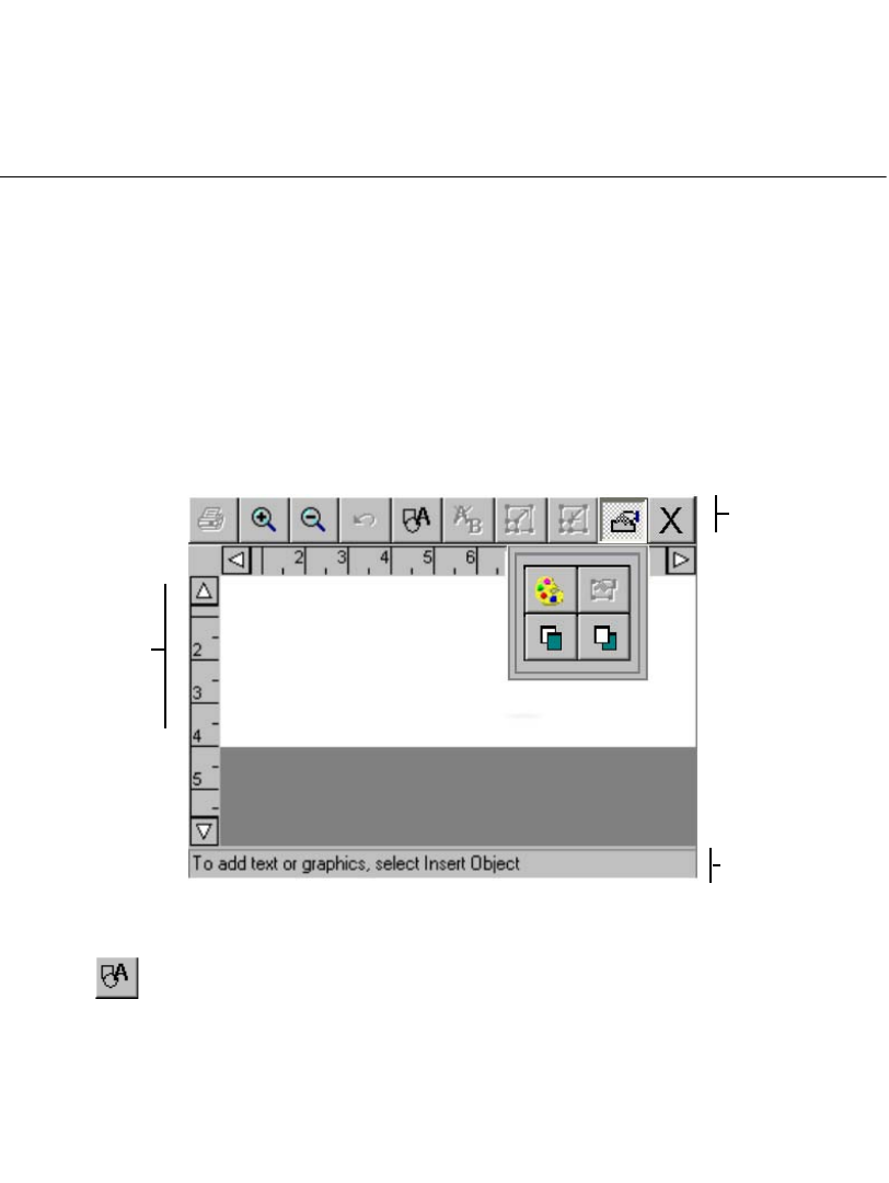
Working with Objects7-3
After you have added an object to a label, you can move it around and make
changes to it. After the label is complete, you can print it, or if you have the Color
& Cut system, you can cut out some object types.
Adding Objects
You can create objects for a label, such as when you write your own text for a label,
and you can insert existing objects on a label, such as when you choose a graphic
from the graphics categories to put on your label. In either case, you are adding an
object to the label.
To add an object to a label
1. Create a new label as described in Creating Custom Labels on page 6-2.
The Editor window is displayed with a blank label in the preview area:
Figure 7-1. The Editor window.
2. Choose the Insert Object button in the tool bar on the Editor window, or press
Insert Object on the keyboard.
Toolbar
Preview
area,
which
displays
your work
as you
create a
label.
Status bar
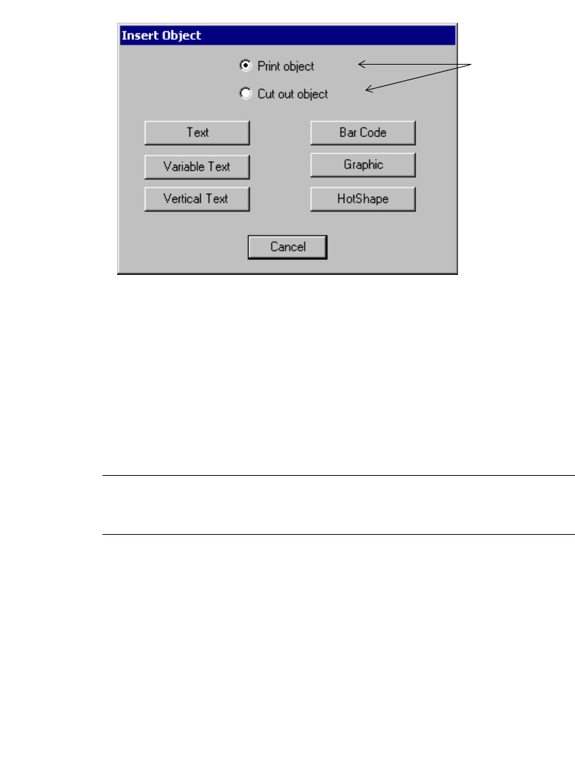
7-4 Adding Objects
The Insert Object screen displays:
These options
available only
on the Color &
Cut system.
Other systems
default to Print
object.
Figure 7-2. The Insert Object screen.
Note that the Insert Object options vary according to your system’s features. The
Monocolor and Multicolor systems do not offer the Cut out object option, so Print
object is assumed and does not appear on the Insert Object screen.
You select options on this screen to choose the kind of label you are going to make,
and to indicate what type of object you want to add. Each type is described in the
sections that follow.
3. If you have the Color & Cut system, choose Print object. All other systems
assume the object is a Print object.
Note: The sections that follow describe Print objects only. To use the Cut out
object option on the Insert Object screen, you must have the Color & Cut
system. See CHAPTER 10: Working with Cut-outs, for instructions.
Adding and formatting text objects
It’s important to understand that when you add a text object, you are not simply
typing text on your label. You create a text object, you type text into the text object,
and you add that text object to your label. This concept is especially useful to
understand for later, when you want to change or edit the objects on your labels.
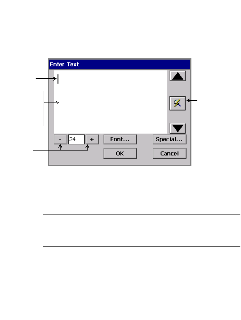
Working with Objects7-5
Adding a text object
This procedure creates and adds a text object to your label.
To add a text object to a label
1. Choose Text from the Insert Object screen.
You’ll see the Enter Text screen
Cursor
(blinking)
Type size
selection
buttons
Background
reflects color of
tape installed.
(Text color
reflects current
drawing color.)
Refresh Screen
button. Use
when entered
text exceeds
the text entry
area.
.
Figure 7-3. The Enter Text screen.
2. Enter text in the text entry area by typing the characters on your keyboard. To
start a new line, press Enter. Note that the size of the text you type as shown in
the Enter Text screen is not the actual size it will be on your label, but is
displayed at a size you can easily edit.
Hint! You can change the type size or font style of the text, or add special
characters to the text, at any point after you open the Enter Text screen,
even before you type any characters. See Formatting text objects on
page 7-6 for instructions.
3. When you are finished, choose OK. You’ll see the Editor window with your
new text object displayed in the preview area.
7-6 Adding Objects
Formatting text objects
The Enter Text screen provides these options for formatting your text object:
To select a font
You can choose from among several font styles, depending on which fonts are
provided with your system. The font is the style and shape of the characters.
You can also use text formatting options to change the style of the fonts to bold,
italic, and underline, or any combination of the three. You can change the color of
your text as well, depending again on how your system is equipped and the supplies
you have installed.
Note: When you apply the text formatting options, the system places invisible
markers to indicate where to apply format changes. Normally you will not
be aware of these markers, but if you inadvertently place the cursor before
a marker, the Delete key will not function.
1. With the text you want to change displayed on the Enter Text screen, select the
part of the text (or all of it) that you want to format.
2. Press Font on the Enter Text screen, shown in Figure 7-3 on page 7-5.
Font Lets you choose the style of the characters. See To
select a font below.
Type size
buttons
Lets you change the size of the characters. See To
change the type size on page 7-7.
Special Lets you insert special characters, like accented
characters, foreign currency symbols, mathematical
symbols, subscripts and superscripts, and more. See
Adding special characters to text on page 7-8.
OK Saves your settings and displays the label in the
Editor window.
Cancel Returns you to the Editor window with a text object
containing no text displayed.
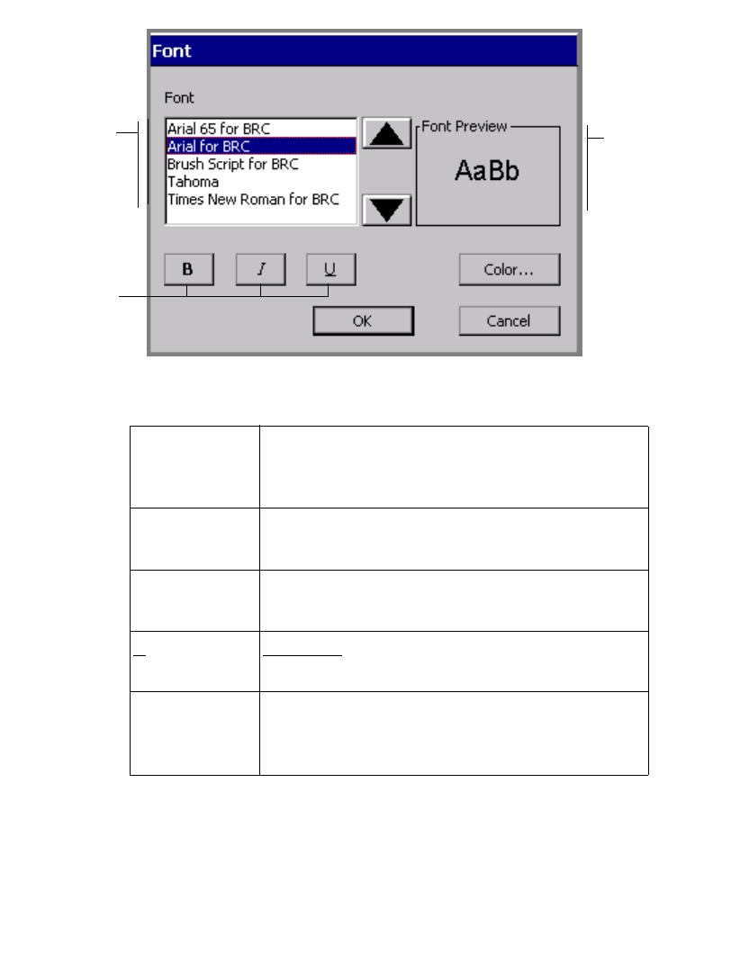
Working with Objects7-7
You’ll see the Font screen:
Font list
varies
according
to system
Displays
a preview
of the
selected
font
Text
formatting
options
Figure 7-4. The Font screen.
The options are:
To change the type size
Changing the type size makes the characters larger or smaller, not just as you see
them on the screen, but on the printed label as well.
1. On the Enter Text screen, select the text you want to change.
Font Lists the fonts installed on your system. As you
select a font, a preview displays in the Font
Preview box.
BBolds the selected text. If no text is selected, Bold is
applied to the next text you type.
IItalicizes the selected text. If no text is selected,
Italic is applied to the next text you type.
UUnderlines the selected text. If no text is selected,
Underline is applied to the next text you type.
Color Takes you to the Color screen appropriate for your
system. See CHAPTER 8: Applying Color, for
complete information about color.
7-8 Adding Objects
2. Use the + or - button to increase or decrease the size of the text. The text
changes size on the Enter Text screen.
Note: The unit of measurement (e.g., points, inches, millimeters) used here is
determined by the defaults set in the System Setup screen. See Setting
Text Tab Options on page 5-12 for details.
3. When you are satisfied with the type size, press OK. The system takes you back
to the Editor window, where you will see changes you made to the label
displayed in the preview area.
Hint! On some types of labels, the system automatically sizes the font. See
Creating QuickText Labels on page 6-5 for information.
Adding special characters to text
You can insert accented characters, subscript numerals, some superscript numerals
and characters, characters in other languages, and other special characters that do
not appear on your keyboard on your labels. For a complete list of special
characters you can add, see Appendix A: Special Characters.
You can also customize your system with Special Characters buttons that display
the special characters you use most frequently. The first time you use the Special
Characters screen, the Special Character buttons are blank. You personalize the
buttons on this screen with your own choice of frequently-used special characters,
so you can access them easily in the future.
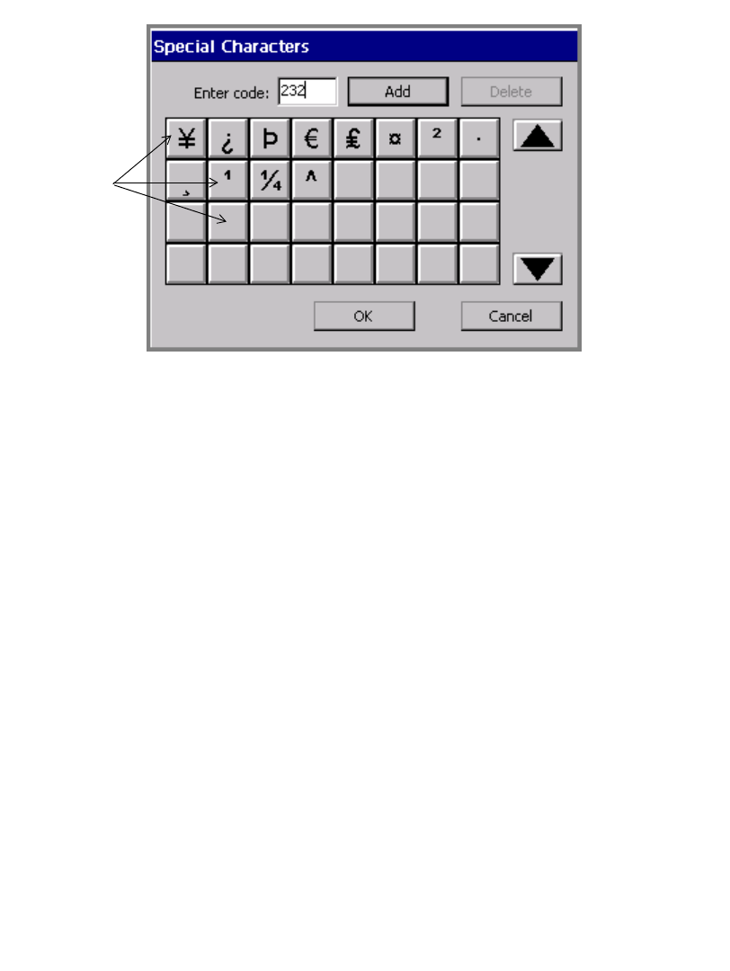
Working with Objects7-9
This example shows some Special Character buttons already personalized.
Figure 7-5. The Special Character screen, customized.
To personalize Special Characters buttons
1. On the Enter Text screen (Figure 7-3), choose Special.
You’ll see the Special Characters screen.
2. Type a code in the Enter code field. The codes available to you depend on the
currently active font. See Appendix A: Special Characters for a list of
characters and codes.
3. Choose Add. The system displays the special character whose code you entered
on the face of the first available blank special character button.
4. Repeat for as many special characters as you want to assign to buttons.
5. Choose OK when complete.
To delete Special Character buttons assignments
1. Select one or more Special Character buttons for which you previously
assigned special characters. Touch each button you want to delete. The system
allows you to delete more than one special character assignment at one time.
2. Press Delete. The special characters previously assigned to those buttons are
removed. Remaining special character buttons are reordered to the top of the
group.
Special
Character
buttons

7-10 Adding Objects
To add a special character to label text
1. On the Enter Text screen, position the cursor where you want to insert a special
character.
2. Choose Special.
You’ll see the Special Character screen.
3. Select a character from the Special Character buttons you previously
customized. Or, if the buttons are still blank, enter the code of the character you
want in the Enter code field.
4. Choose OK.
Hint! You do not have to personalize a Special Characters button to use a
special character. Just enter the code and press OK.
To add multiple special characters to label text
1. On the Enter Text screen, position the cursor where you want to insert a special
character.
2. Choose Special.
You’ll see the Special Character screen.
3. Select multiple special character buttons before you choose OK.
4. Choose OK. You’ll see the Text Entry screen displayed with all characters you
selected added at the cursor position. The characters are added in the order you
selected them.
Adding variable text objects
You can design labels that automatically generate multiple labels from a single
label layout. For instance:
zYou can make a set of labels that look the same but are numbered sequentially,
or a group of labels formatted the same, but with different names on them.
zYou can create a set of labels to number packing boxes when you move, or a set
of alphabetic labels you can use to organize file folders.
zYou can create a set of name labels for the members of your group.
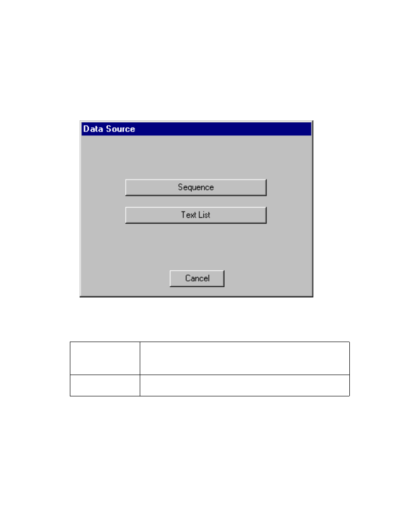
Working with Objects7-11
The object that varies with each group of labels is called a variable text object.
Variable text can consist of either Sequence (numerical or alphabetical characters
sequentially added to a group of labels) or a Text list (such as names of items) data.
The first step in creating labels with variable text is to choose a data source for the
labels.
Choosing a data source
From the Insert Object screen (Figure 7-2), select the Varia ble Text button. The
Data Source screen displays.
Figure 7-6. The Data Source screen.
The options are:
Creating sequential labels
To create sequential labels, choose Sequence on the Data Source screen.
Sequence Data consisting of increasing or decreasing numbers
or alphabetic letters
Text l ist Data consisting of a list of items you create
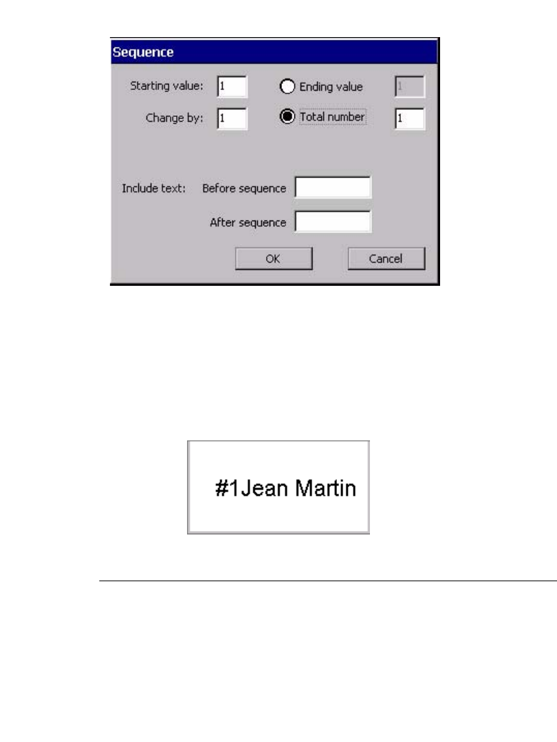
7-12 Adding Objects
Use the options on the Sequence screen to define a Sequence variable text object
or variable bar code object for your labels.
Figure 7-7. The Sequence screen.
For example, the screen shown above defines a set of ten labels that user Jean
Martin plans to use to identify packing boxes. The labels are set to be numbered
from 1 to 10, with the text “#” before the sequence, and the text, “Jean Martin” after
the sequence.
With the information entered as shown in Figure 7-7, the system would produce ten
labels similar to this one, numbered 1 through 10 consecutively:
Figure 7-8. A sample Sequence label
Hint! Make sure the text object you define is large enough to accommodate all
possibilities in your sequence.
For instance, in the example above, if Jean Martin creates 100 numbered
labels, when the system prints the label with the number 100, the text area
Working with Objects7-13
may no longer be large enough for the entire text string. The text will be
cut off on the printed label.
The Sequence options are:
Starting value Enter the starting value for the sequence in this
field. You can enter any number, or a single letter of
the alphabet, but you may not mix both letters and
numbers in a single sequence. (You may, however,
enter alphabetic or symbol characters if the first
character entered is a number: for example, 1A, 2%,
3*.) The default value is 1.
Change by Enter the amount by which you want the sequence
to change on each label. A positive number
increases the number or letter of the alphabet on the
label; a negative number decreases the number or
letter of the alphabet on the label. The default value
is 1, but you can use larger increments with numeric
sequences.
Note: When you use the letters of the alphabet as
the sequence, the only valid values for this field are
1 and -1.
Ending value Enter the ending value for the sequence. Using the
Starting value, the Change by value, and the
Ending value, the system calculates the total
number of labels to be generated for the sequence,
and enters it in the Total number field. The default
value is 1.
Hint! You can leave this field blank and instead
enter the Total number of labels you want to
produce, and the system automatically calculates
the Ending value for you.
7-14 Adding Objects
Creating text list labels
A classic example of variable text labels is name tags for attendees of a convention.
A sample label might look like this one;
The top line and the bottom line are the same for all labels. By listing the members’
names on a Text list, every label produced will contain a different name. The next
label will print with the next name on your Text list, and so on.
Total number Enter the total number of labels you want to
produce in this field. The default value is 1.
Hint! You can leave this field blank and instead
enter the Ending value for labels you want to
produce, and the system automatically calculates
the Total number for you.
Before sequence Enter text that you want to print on all labels in the
sequence before the sequence number or letter.
Note that text you enter here will be exactly the
same on each label.
After sequence Enter text that you want to print on all labels in the
sequence after the sequence number or letter. Note
that text you enter here will be exactly the same on
each label.
OK Press when you are ready to save your entries and
create the sequence object. Your new variable text
object appears on the Editor window.
Cancel Choose to return to the Editor window without
saving entries you made.
Hello! My name is
Jean Martin
Global Industries, Ltd.
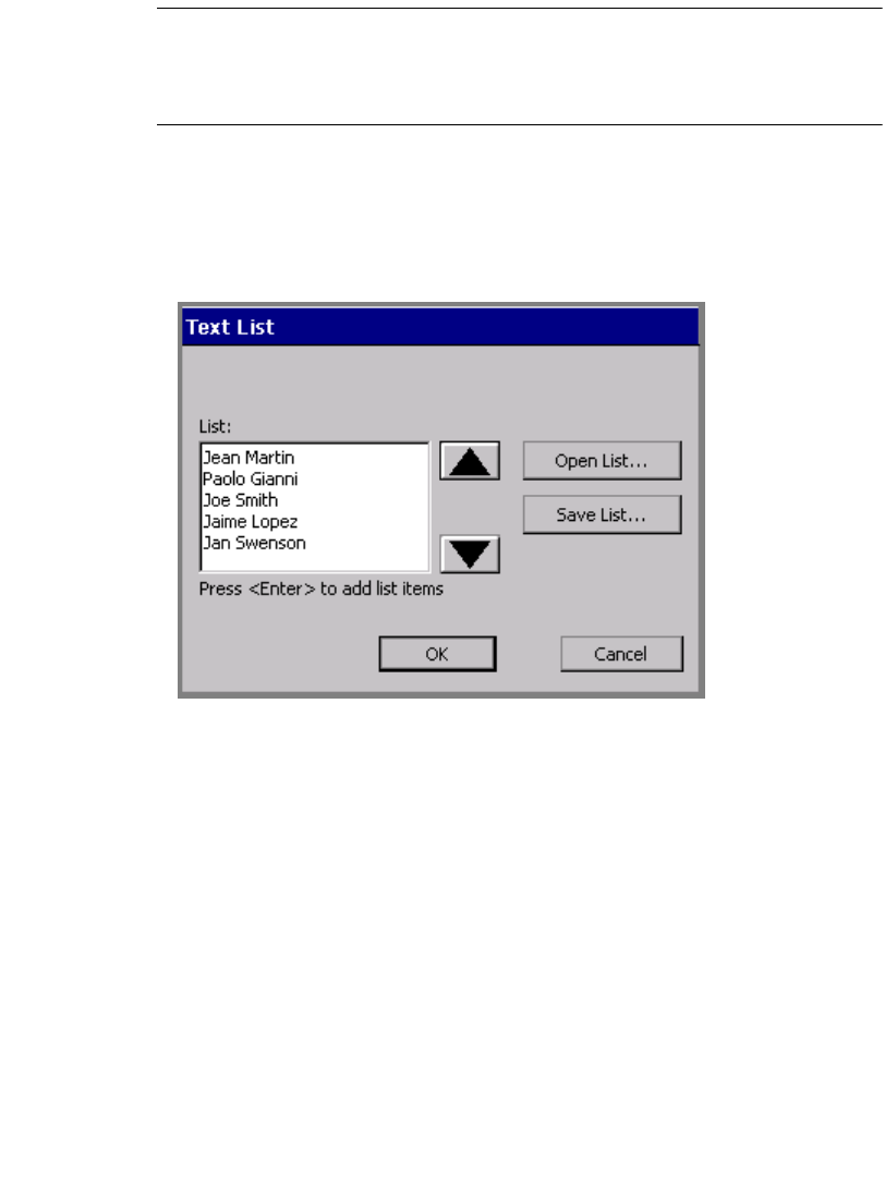
Working with Objects7-15
Hint! Make sure the text object you define is large enough to accommodate all
possibilities in your sequence. For instance, in the example above, make
sure the object is large enough to accommodate the longest name on your
list.
To create a Text list
1. Choose Text List on the Data Source screen (Figure 7-6).
You’ll see the Text List screen, which you use to enter the list of words you
want to use on your labels:
Figure 7-9. Text List screen with example.
2. Type the first item you want to appear on a label.
3. Press Enter.
4. Repeat Steps 2 and 3 for each label you want to print.
5. You can choose to save text lists you create for future use, or you can just use
the list once:

7-16 Adding Objects
• To use the list once, then discard it, press OK.
• To save your list, press Save List when the list is complete. You’ll see the
Save Text List screen. Name your new list in the Enter list name field,
then press OK.
The Editor window displays, with the first item on your Text list shown on the
label.
To use saved Text lists
You can use a Text list you saved previously to create a new set of labels with the
same variable text. For instance, if you have a list of club members saved, you can
use that same list to create name tag labels, mailing labels, and so on.
Hint! If your system is connected to a PC, you can also download list files from
files stored on the PC. See CHAPTER 12: Connecting to a PC,
beginning on page 12-1, for instructions.
1. Choose Text List on the Data Source screen (Figure 7-6 on page 7-11).
You’ll see the Text List screen (Figure 7-9 on page 7-15).
2. Choose Open List. The Select Text List screen displays.
3. Select a list from the Select list box, and press OK.
The Text L ist box appears, with the entries from the list you previously saved
displayed.
4. Choose OK to return to the Editor window.
Adding vertical text objects
Select Vertical Text on the Insert Object screen (Figure 7-2 on page 7-4) to add
vertical text objects to your labels.
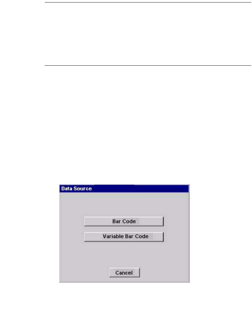
Working with Objects7-17
Note: The characters appear horizontally on the screen as you type the text.
When you press OK, the vertical attribute is applied and the text appears
vertically on the label.
The label orientation does not change when you insert a vertical text
object. To manually change the label orientation, go to the Label
Properties screen. See Changing Label Properties on page 6-27 for
details.
To change the text orientation to vertical after you have created an object, go to the
Options tab on the Object Properties screen. See Setting options on the Options
tab on page 7-40.
Adding bar code objects
Select Bar Code on the Insert Object screen (Figure 7-2 on page 7-4) to add bar
code objects to your labels.
The first step in creating bar codes is choosing a data source.
Choosing a bar code data source
From the Insert Object screen (Figure 7-2), select the Bar Code button. The Data
Source screen displays.
Figure 7-10. Data Source
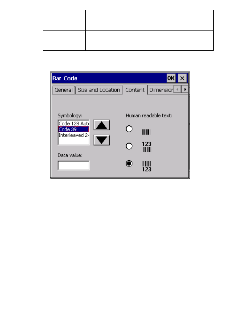
7-18 Adding Objects
The options are:
If you select Bar Code on the Data Source dialog box, the Bar Code dialog box
displays where you can specify the content of the bar code.
Figure 7-11. The Bar Code screen Content Tab.
The Bar Code screen has five tabs. When you add a bar code, you’ll use the
Content and Dimension tabs. The remaining tabs -- General, Size and Location,
and Font -- are mainly used to change default settings for bar codes (see Editing bar
codes on page 7-21).
Bar Code The Bar Code dialog box displays with the Content
tab activated.
Variable Bar
Code
The Sequence dialog box displays.
Working with Objects7-19
Setting bar code content
Use the Content tab to set these options:
Symbology Select a symbology code from this list box.
Symbologies are universal bar code formats.
This system supports these symbologies:
•Code 128 Auto
•Code 39
•Interleaved 2-of-5
Data value Specify a data value for the bar code here. The
symbology codes limit the data to a specific number
of characters:
Symbology
Code 128 Auto
Code 39
Interleaved 2-of-5
Max. # Characters
2-50
2-50
2-50
•If you enter an incorrect number of characters in
the Data value field, a message prompts you for
a corrected value.
•If you enter invalid characters in the Data value
field, you’ll see a message telling you so.
Human-readable
text
Select the placement of the text that people can read
(as opposed to machine-readable code). You can
choose:
•No text
•Text above bar code
•Text below bar code (the default)
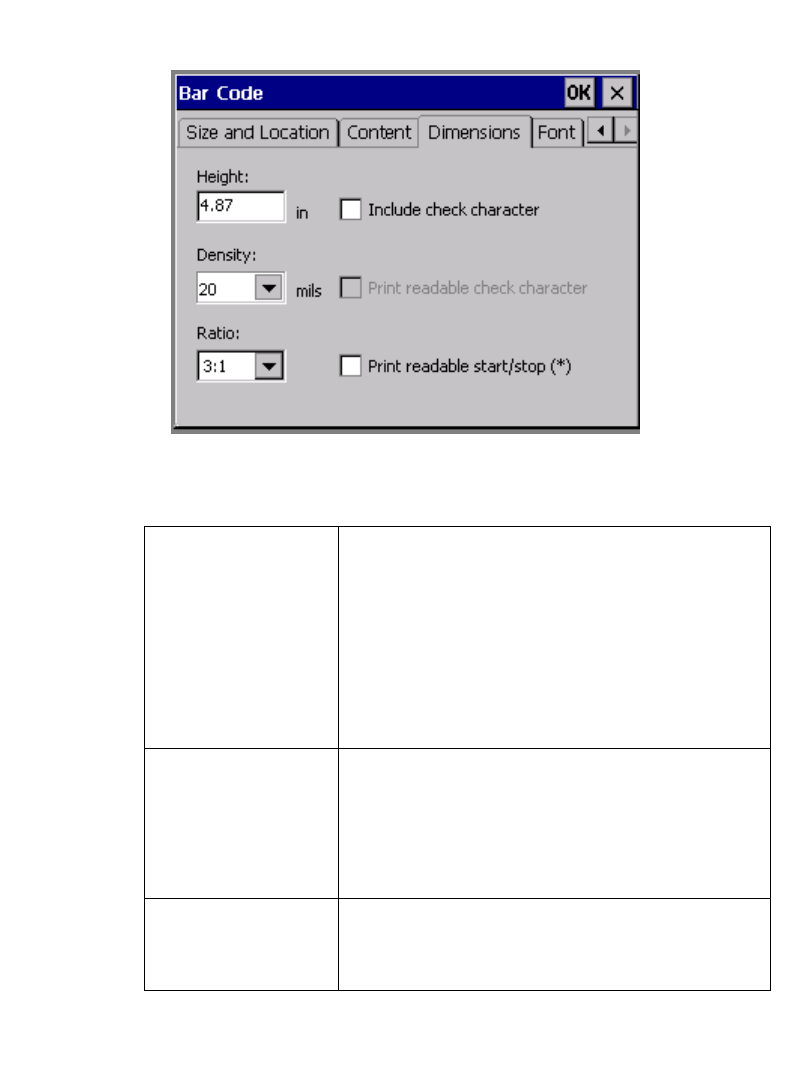
7-20 Adding Objects
Setting bar code dimensions
Choose the Dimension tab on the Bar Code screen to set bar code measurements:
Figure 7-12. The Bar Code screen, Dimensions tab.
Use the Dimension tab to set these bar code options:
Height Set the bar code height (in the unit of measure
specified on the System Setup screen Localization
tab) by entering a height or choosing from the
options list.
Hint! If you want to make a bar code taller,
setting the height here is preferable to using the
Height option on the Bar Code Size and Location
tab.
Density Set the density in mils by choosing from this list.
The density is the thickness of the bars and how far
apart they are.
Hint! This setting determines the width of the
bar code.
Ratio Set the width ratio by choosing from this list. Ratio
determines the relative width of the wide bars to the
narrow bars in the bar code.
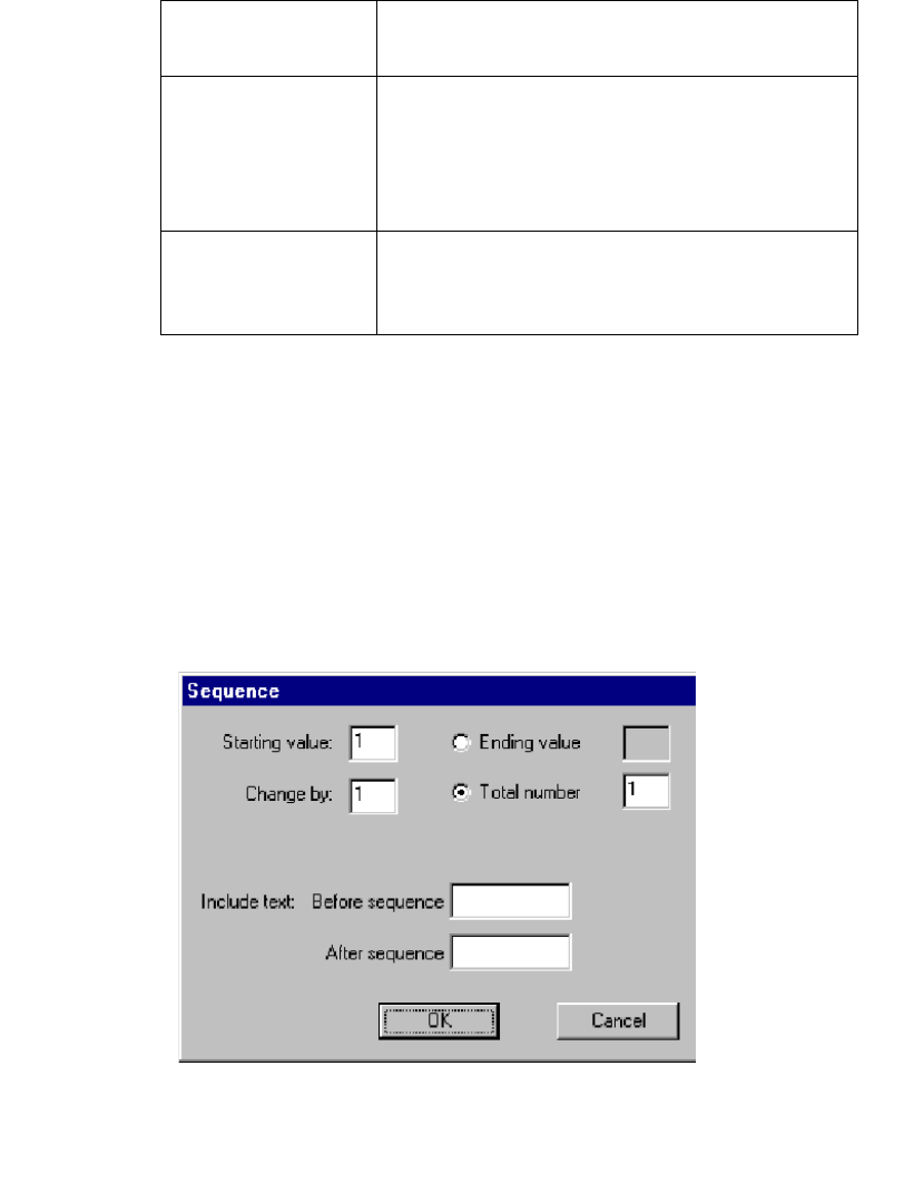
Working with Objects7-21
Editing bar codes
Of the remaining tabs, General, Size and Location, and Font, only Location has
options that apply to bar codes. The options on the remaining tabs correspond to the
options on the same tabs in the Bar Code Properties screen. See Changing object
properties on page 7-32 for information about these options.
Specifying bar code sequence
You select the bar code sequence from the sequence dialog box. For explanation of
the Sequence dialog box options, see Creating sequential labels on page 7-11.
Figure 7-13. Sequence dialog box,
Include check
character
Check this box if you want to print a check
character on the label.
Print readable check
character
Check this box if you want to print a check
character on the label in a format people can read.
This option is unavailable (and therefore grayed out
on your screen) unless you have already checked
Include check character.
Print readable start/
stop (*)
Check this box to indicate whether the start and stop
characters (which are asterisks) should appear in
human-readable text.
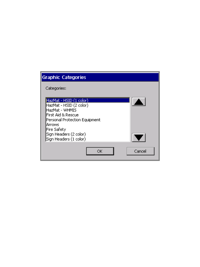
7-22 Adding Objects
Adding graphics objects
You choose graphics from groups of pre-defined graphics supplied with your
printing system. The graphics are organized in categories, with the name of the
category shown. After you select a graphic category, you’ll see small versions of
the graphics on your screen. You can look at all graphics offered in a category, and
you can change categories.
To add a graphic object
1. Select Graphic on the Insert Object screen (Figure 7-2 on page 7-4). You’ll
see the Graphic Categories screen:
Figure 7-14. The Graphic Categories screen.
2. Choose a category of graphics from the list. Use the arrow scroll buttons to
move up and down the list.
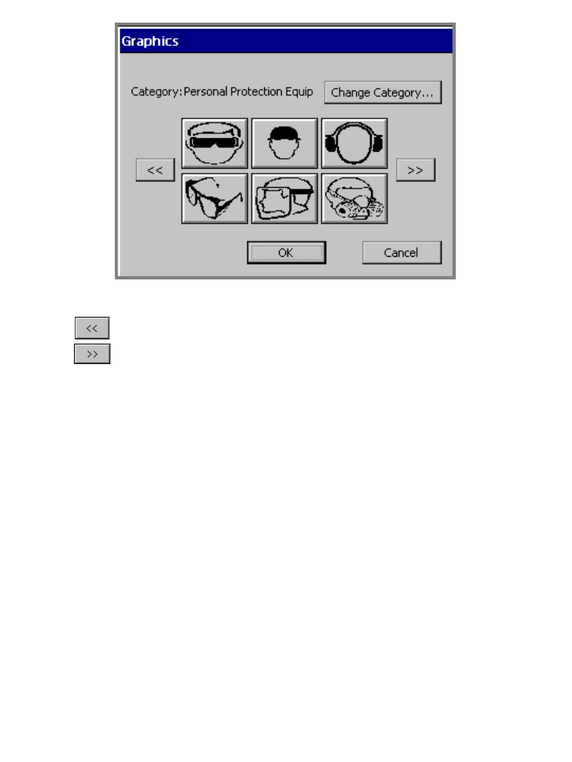
Working with Objects7-23
3. Choose OK. The Graphics screen displays:
Figure 7-15. The Graphics screen.
Use the arrow buttons to step through thumbnail versions of the graphics
offered in the category shown. Each time you press a scroll button, you’ll see
six (or fewer, depending on how many graphics are available in the category)
new thumbnail graphics.
4. Select the thumbnail button that displays the graphic you want to add to your
label.
5. Click OK. The system adds the graphic object to your label.
To change graphics categories
1. Choose Change Category on the Graphics screen. You’ll see the Graphic
Categories screen (Figure 7-14 on page 7-22) again, which lists all categories
offered in your system.
2. Choose a category from the list and press OK. The Graphics screen displays
again, this time displaying thumbnail versions of graphics from the new
category you selected.
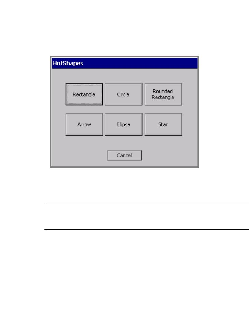
7-24 Adding Objects
Adding HotShapes
HotShapes are pre-defined designs you can print on your label. If you have the
Color & Cut system, your printer can automatically cut out these shapes. See
CHAPTER 10: Working with Cut-outs, for more information.
To add HotShape objects to your label, select the HotShape option on the Insert
Object screen (Figure 7-2 on page 7-4). The HotShape screen displays.
Figure 7-16. The Hot Shapes screen.
Choose a HotShape by selecting one of the HotShape buttons. The HotShape
object is automatically added to your label on the Editor window.
Hint! You can change the size, color, rotation, and location of a HotShape object
just like any other type of object, but you may not open and edit a
HotShape.
To cancel adding a HotShape and return to the Editor window, choose Cancel.
Working with Objects7-25
Selecting Objects
You must select an object in the Editor window before you can move, resize, copy,
or edit it. (See Selecting in the Editor window on page 4-7 for detailed information
about selecting text objects using the touch screen, the keyboard, or the mouse.)
In brief:
You can tell an object is selected when a bounding box, which is a gray rectangle
that encloses the object, appears on the screen. The bounding box has small
squares, called selection markers, at the corners and midpoints of the sides.
Note: Depending on the resolution of your machine and the features it contains,
the sides of the bounding box may be dim or may not be visible at all. But
the selection markers will always display to indicate that an object has
been selected.
If you select more than one object, the bounding box expands to enclose all the
objects. See Figure 4-3 on page 4-8 for an example that shows a bounding box.
Hint! The ‘click’ you hear when you touch the screen indicates only that you
have touched the screen with enough force for the system to recognize the
touch. The click does not necessarily indicate that you have successfully
selected an object on the screen.
A second ‘button activated’ cue sounds when you have successfully
activated a button or control on the touch screen. The ‘button activated’
sound applies to the Command buttons and the Up and Down Scroll
buttons. The ‘button activated’ sound does not apply to the OK and X
To: Do this:
Select an object Touch the object
Select a different object Touch another object. The new object is
selected.
Select multiple objects Touch each object while holding down the
Shift key.
Select no objects or deselect
the object selected
Touch the label background where there
are no objects. All objects will be
deselected.
7-26 Moving Objects
(Close) buttons in the dialog box title bar, the Tab controls in the property
screen dialog boxes, Radio buttons, or Option List items. See Working
in Entry Screens on page 4-9 for more information.
Selecting a layered object
When you have multiple layered objects on a label, it can be difficult to see and
select the object of your choice. In some cases, you may be able to move the objects
aside temporarily to find the object you want, but this alternative is not always
practical on a crowded display screen.
To find and select a layered object
1. First, make sure you have an object, any object, selected on the screen.
2. Press Tab to cycle through all the objects on the screen one by one.
Hint! To help identify the object selected, press Object Properties and review
the object’s characteristics.
Moving Objects
The Move to Back and Move to Front buttons make it easy to move objects on the
screen.
Hint! You can also assign a precise location for objects using the options on the
Size and Location tab of the object Properties screens. See Setting
options on the Size and Location tab on page 7-36 for more information.
To move an object using the touch screen
1. Touch the object to select it.
2. Click the Properties button to display a second row of functions, which
contains the Move to- buttons.
3. Click the Move to Back button to move the selected object to the back of any
layered objects.

Working with Objects7-27
OR
Click the Move to Front button to move the selected object to the front of any
layered objects
4. Move your finger on the screen to take the object to its new location.
To move an object by keyboard
1. Select the object.
2. Press an arrow key on the keyboard.
3. Repeat pressing the arrow key or hold it down until the object is where you
want it.
Each key press moves the object by one-tenth of an inch, so the procedure above
works well for moving objects a small amount. If you hold down the arrow key, the
moving process goes a little faster. But to move objects by a greater amount, there
is a speedier process:
To move objects faster and farther
1. Select the object.
2. Hold down Shift.
3. Hold down the arrow key.
Sizing Objects
You have several options for sizing objects on the Editor window:
zUse the Increase Size or Decrease Size tools. This method is good for small
changes. See the Using Increase Size and Decrease Size section below for
instructions.
zUse the <Scale> key on the keyboard. Use this method for size changes of 25%
and greater. See Using the Scale function on page 7-28 for instructions.
zUse the Object Properties tool or press the Object Properties key to set the
absolute size of an object. To learn about this process, see the Changing object
properties on page 7-32

7-28 Sizing Objects
Using Increase Size and Decrease Size
The Editor window toolbar provides these two size tools, which increase or
decrease the size of the selected object proportionally by 10% of its original size
each time you select the tool.
zWhen you select Increase Size, your selected object becomes 10% larger than
its original size. If you repeat Increase Size, your selected object becomes 10%
larger than its new size.
zWhen you select Decrease Size, your selected object becomes 10% smaller
than its original size. If you repeat Decrease Size, your selected object becomes
10% smaller than its new size.
Use the Increase/Decrease Size tools when you want to make a small size change,
or when you need to make the change in 10% increments.
Hint! Increase/Decrease Size changes are always proportional, which means
that you change the width and height of the object at the exact same rate of
change. The shape of the object remains the same, though the size
changes.
To resize an object using the Size tools
1. Select the object.
2. Select Increase Size or Decrease Size.
The object remains selected, and the size changes by 10%.
3. Repeat Step 2 to continue changing the size by 10% of the original size.
Using the Scale function
Use <Scale> on the keyboard when you want to resize an object by 25% or more
and still maintain its original proportions. When you use the Scale function, you
choose a percentage that will reduce or increase the current size of the selected
object by that amount. For example:
zWhen you choose 25%, the object is reduced to 25% of its current size. If you
repeat the process, the object is reduced to 25% of its new size.
zWhen you choose 150%, the object is enlarged to 150% of its current size. If
you repeat the process, the object is enlarged to 150% of its new size.
Working with Objects7-29
Hint! Scaling is always proportional, which means that it changes the width and
height of the object at the exact same rate of change. The shape of the
object remains the same, though the size changes.
To resize an object using Scale
1. Select the object
2. Press the Scale key on the keyboard.
The Scale screen displays.
Figure 7-17. The Scale screen.
3. Choose one of the percent buttons.
or
Enter a percentage in the Percent field.
• Percent field minimum = 10%
• Percent field maximum = 500%
Hint! Use the Percent field for percentage amounts not provided on the percent
buttons.
If you enter a percentage outside the range, a system message directs you to re-
enter a valid value.
7-30 Copying and Pasting Objects
Scaling text objects
Using <Scale> on text objects is not recommended, as it may result in the text
wrapping to more or fewer lines on the label. (Resizing using the Increase/
Decrease Size tools may have the same result.) If the Auto Size Font option on the
Options tab of the Text Properties screen is turned on, the text size changes as the
object is scaled. See Adding and formatting text objects on page 7-4 for
information on Text objects.
Scaling bar codes
The size of the human-readable text does not change when you use <Scale> to
resize a bar code. See Adding bar code objects on page 7-17 for information.
Copying and Pasting Objects
When you copy an object, the system leaves the object in its original location, and
places a copy of the object in the system’s internal memory. This lets you paste the
object into another location.
To copy an object
1. Select the object using any of the methods described in Selecting Objects on
page 7-25.
2. Press the <Copy> key, or use the Ctrl+C key combination.
A copy of the object is placed in the system’s internal memory. The original
stays where it is.
Hint! You can delete the original object while it is still selected by pressing
Delete or Ctrl+X.
To paste an object
1. Copy the object you want to paste.
2. Press Paste, or use the Ctrl+V key combination.
Working with Objects7-31
The object is pasted in the center of display screen. You can move it to any
location on the screen. Use the methods described in Moving Objects on
page 7-26.
Hint! You can paste multiple instances of an object by repeating Paste or
Ctrl+V.
Changing Objects
You make changes to an object by opening and editing it, or by changing its object
properties.
Opening and editing an object
You must open an object for editing before you can make changes to it.
To open an object
1. With your label displayed in the Editor window, select the object to be edited.
Use any of the methods described in Selecting Objects on page 7-25.
2. Choose Edit Object on the toolbar, or press Edit Object on the keyboard.
Depending on the type of object selected, you’ll see one these screens:
Text object Enter Text screen, described in Adding and
formatting text objects on page 7-4.
Variable text object Sequence screen, described in Creating sequential
labels on page 7-11, or Text List screen, described
in Creating text list labels on page 7-14, depending
on the type of variable text.
Bar code object Bar Code screen, described in Setting bar code
dimensions on page 7-20
Graphic object Graphics screen, described in Adding graphics
objects on page 7-22.
7-32 Changing Objects
To edit an object
Use the fields and options on the screen that displays after opening the object, as
shown in the table above, to make changes.
Changing object properties
Instead of manipulating the object you want to change within the Editor window as
described in the preceding sections, you can use the options on the Properties
screens to reset the properties of the objects. The Properties option let you control
the physical properties of your objects, such as height, width, location, and color.
Important! The object Properties screens, tabs, and options vary according
to the features your system offers and the properties of the type of
object you have selected.
All objects that you can place on a label have common properties, such as height
and width, location, and color. Some objects have properties unique to their type,
such as text alignment (text objects), or bar code symbology (bar code objects). So
while all the Properties screens have many options in common, they have different
titles and also offer different options for each type of object.
The Properties screens and tabs displayed for each type of object are:
Text objects Text Properties screen, with tabs:
General
Size and Location
Font
Placement
Options
Variable text objects Text Properties screen, with tabs:
General
Size and Location
Font
Placement
Options
Working with Objects7-33
The type of system you have also determines the options offered on each tab. For
instance, the Cut out object option does not appear at all on the Properties screens
of the Monocolor or Multicolor systems. Only Color & Cut systems contain the
Cut out object option. Also, some options may be shown on the screen, but appear
to be grayed out, which means they are unavailable for your system or for that
object type.
Hint! For text objects and HotShape objects, you can change a print object to a
cut out object and vice-versa. Go to the General tab on the object’s
Properties screen and choose the appropriate option.
Remember, however, that no object can be both a print object and a cut out
object at the same time, so if you change a print object to a cut out, you
need to change it back again before you can print it again. See CHAPTER
10: Working with Cut-outs, for more information.
To change object properties
1. With your label displayed in the Editor window, select the object you want to
change, using any of the methods described in Selecting Objects on page 7-25.
2. Choose Object Properties from the toolbar, or press Object Properties.
Bar Code objects Bar Code Properties screen, with tabs:
General
Size and Location
Font
Placement
Options
Graphic objects Graphic Properties screen, with tabs:
General
Size and Location
Hot Shape objects HotShape Properties screen, labelled according to
the HotShape selected, with tabs:
General
Size and Location
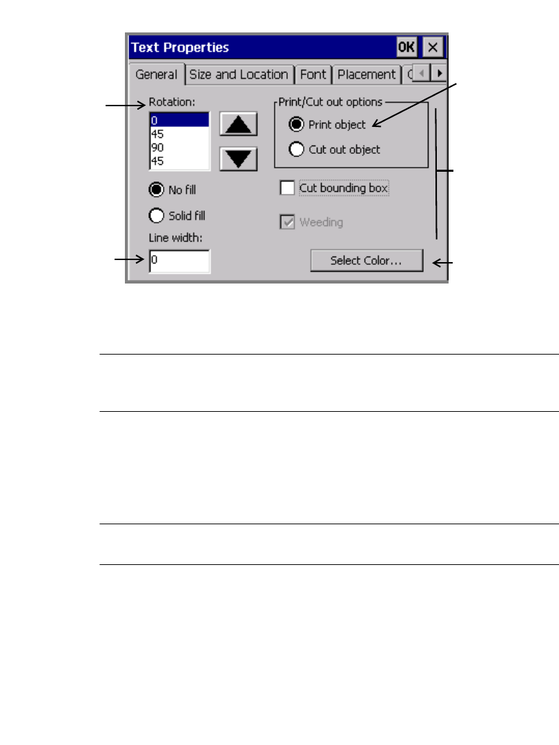
7-34 Changing Objects
You’ll see the a Properties screen with tabs and options appropriate to the
object selected. This is a sample Text Properties screen:
Available on
Color & Cut
system only
Available on
all systems,
for all objects.
For bar
codes, limited
to 0 and 90.
Available on all
systems, for all
objects
Available on
all systems,
for all objects
Print object is
assumed on
Monocolor
and Multicolor
systems
Figure 7-18. A generic Properties General tab.
The values shown on the screen are the current values of the selected text object.
Note: Object Properties screens are not accessible from the Pipe Marker or
Right-To-Know applications. You must use the Preferences key to change
properties for those specialty applications.
Setting options on the General tab
The General tab appears on the Properties screens for every type of object. Use
the options on the General tab to set the rotation, the fill, the cut options, the line
width, and to begin the select color process
Note: As noted below, options offered on the General tab vary according to your
system features.
Working with Objects7-35
The General tab options are:
Rotation For all systems. Use the scroll arrows to choose
from the list of rotation angles. For example, to
rotate an object 45 degrees, choose 45.
Note: For bar code objects, the only valid values
are 0 and 90 degrees.
After rotating an object, you may not set an absolute
size for that object. You may, however, use the
Increase Size and Decrease Size tools to change
the size. (See Using Increase Size and Decrease
Size on page 7-28)
No fill/Solid fill These options appear on the HotShape Properties
General tab only. Select to set the default fill for the
HotShape object. The fill is the background pattern
inside the object. Choose:
•No fill to leave objects transparent.
•Solid fill to make the background inside the
object a solid color.
Print/Cut out For the Color & Cut system only. Set to indicate
that the object is for printing or to be cut out. In the
Monocolor and Multicolor systems, print object is
the only option. See Creating Cut Out Objects on
page 10-3 for complete information.
Cut bounding box For the Color & Cut system only. Use to apply a
bounding box to a print object, so the object can be
cut out.
Weeding For the Color & Cut system only. Use to apply a cut
around the outside of a cut text object. You can then
strip the waste from around the text.
Line width field For all systems. Use to set and to view a line width
for a frame for a text object. The default is 0, which
indicates that the object is not framed. A sample of
the line width you select is shown next to the field.
See Figure 7-18 on page 7-34.
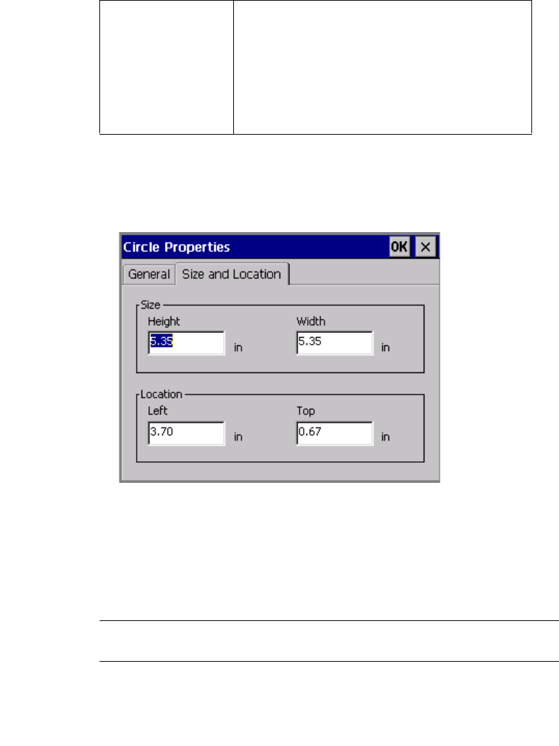
7-36 Changing Objects
Setting options on the Size and Location tab
The Size and Location tab appears on Properties screens of all object types. Use
its options to set the height, width, and location of an object. The following is an
example of a (HotShape) Circle Properties Size and Location tab screen:
Figure 7-19. The Circle Properties Size and Location tab.
To set the size of an object
You can set the absolute size of most objects by setting the height and width on the
Size and Location tab. When you set an absolute size for an object, that object
remains the same size regardless of other operations you perform.
Note: If you previously rotated an object, the Size options are not available on
the Size and Location tab.
1. Select an object.
Select color button For all systems. Select to change colors for the
object. See Applying Color to Objects on page 8-
5.
Note: You may not change the colors of a multi-
color graphic object supplied by the system. You
may, however, change the entire color of a single-
color graphic.

Working with Objects7-37
2. Press Object Properties to get to the object’s Properties screen.
3. Choose the Size and Location tab.
Note: To set height and width for bar code objects, we recommend that you use
the options on the Bar Code screen Dimensions tab instead of the Size
and Location tab. See Adding bar code objects on page 7-17 for more
information.
4. Enter a height in inches or millimeters in the Height field.
5. Enter a width in inches or millimeters in the Width field.
6. When you complete all settings changes on the Size and Location tab, click
OK. The size you set becomes the default size for the object.
To set the location of an object
The advantage to using the options on the Size and Location tab to set the location
for an object is that you can choose a precise location. This is useful for laying out
complex labels, or when you want to line up multiple objects on a label.
To set location, think of the screen as a grid with the origin of 0,0 at the upper left
corner of the printable area of the label.
For example, if you set the Left field to two inches and the Top field to one
inch, the object prints two inches from the left of the label and one inch from the
top of the label.
Note: If you previously rotated an object, the Location options are not available.
1. Press Object Properties to get to the object’s Properties screen.
2. Choose the Size and Location tab.
3. In the Left field, enter the number of inches or millimeters from the left side of
the printable area where you want to locate the object.
4. In the To p field, enter the number of inches or millimeters from the top of the
printable area where you want to locate the object.
5. If you have completed all settings changes, click OK. The location you set
becomes the default location for the object.
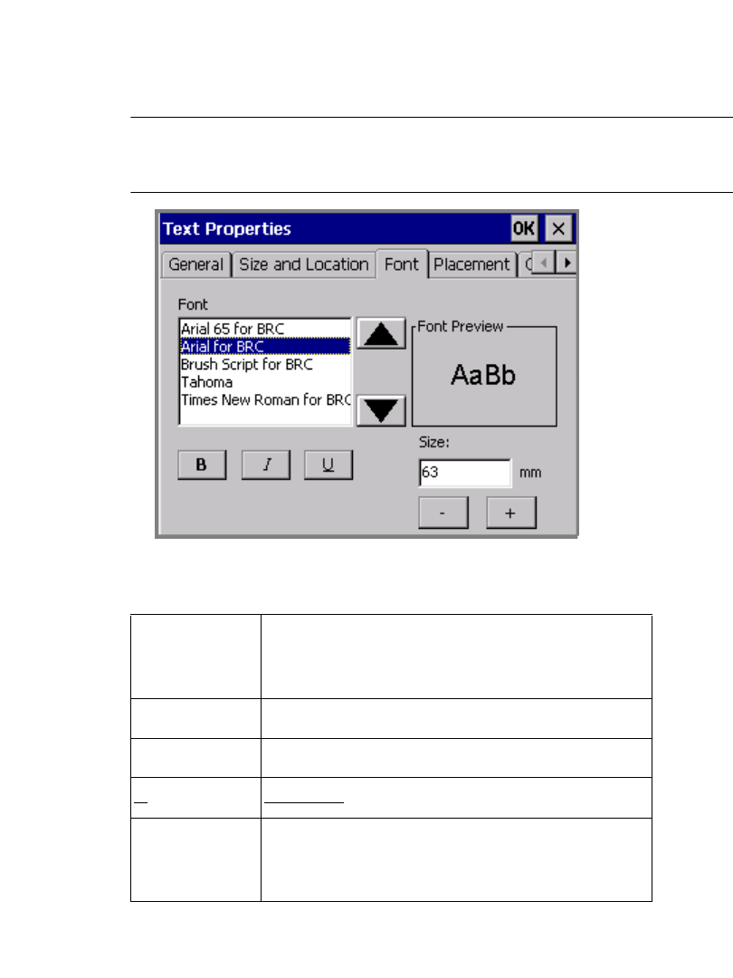
7-38 Changing Objects
Setting options on the Font tab
Use the Font tab to change the font options for the selected text object. The
Font tab is included on the Text Properties screen and on the Bar Code
Properties screen.
Note: Changes you make using the Font tab options apply to the entire text
object, and may override formatting changes you previously made to the
text characters.
Figure 7-20. The Text Properties Font tab.
The options are:
Font Lists the fonts installed on your system. As you
select a font, a preview displays in the Font
Preview box.
BBolds all the text in the entire object.
IItalicizes the text in the object.
UUnderlines the text in the object.
Size (+ or -) Determines the size of the characters. Setting the
type size here makes the characters larger or smaller
both on the screen and on the printed label as well.
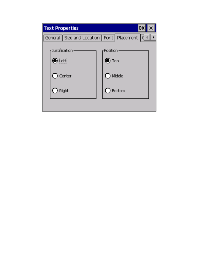
Working with Objects7-39
Setting options on the Placement tab
Use the options on the Placement tab to set justification and position for text
objects.
Figure 7-21. The Text Properties Placement tab.
Justification determines the horizontal alignment for a text object in your label.
Choose:
•Left for traditional left-to-right justification, with text positioned against the
left side of the text object
•Center to position the text in the horizontal center of the text object
•Right to position the text against the right side of the text object
Position determines the vertical alignment of a text object in the label. Choose:
•Top to position the text at the top of the text object
•Middle to position the text in the middle of the text object
•Bottom to position the text at the bottom of the text object
7-40 Changing Objects
This sample label demonstrates both justification and position.
Setting options on the Options tab
Use the options on the object Text Properties screen’s Options tab to set various
text object properties:
Figure 7-22. The Text Properties Option tab.
The options are:
Free form text
object
Choose to indicate that the selected text is a free
form text object, which means that the object size is
based on the amount and the size of the text inside.
If you change the amount of text inside, the object
size changes too. This type of text object is the
opposite of a text object with boundaries.
Left-justified text, top position
Right-justified text, bottom position
Centered text, middle position
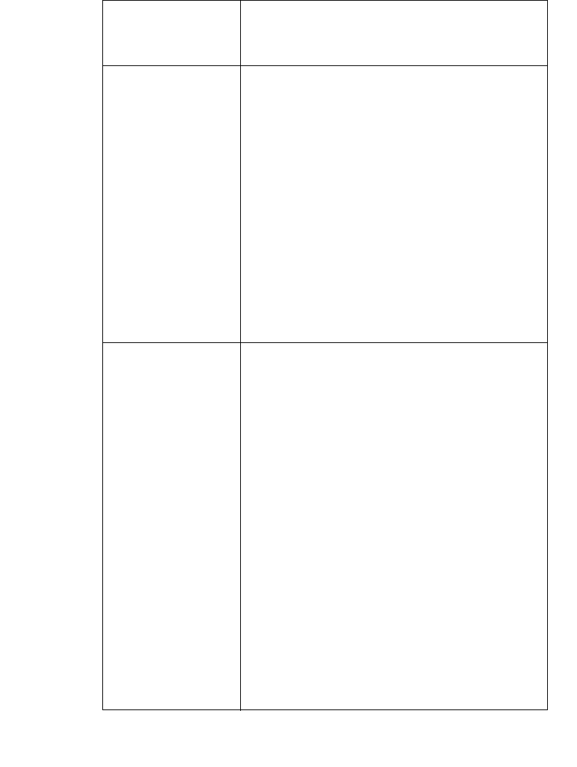
Working with Objects7-41
Text object with
boundaries
Choose to indicate that the text object has set
boundaries. This type of text object is the opposite
of a free form text object.
Expand/Condense
text
Create text, and then expand and condense text
horizontally according to the percentage selected.
Applicable percentages are
z·25%
z·50%
z·75%
z· 150%
z· 200%
If you select Free form text object or Text object
with boundaries, the percentage combo box will be
inactive.
If you change the expand/condense text option to
either Free form text object or Text object with
boundaries, the default type size in the Font tab
(text properties) will be used.
Auto size font Available only when a text object with boundaries is
selected. Choose to tell the application to
automatically set the point size of the text to fit
within the text object. The appropriate point size is
implemented for your text.
The limiting dimension is determined by the width
or height of the text. When the text meets either the
horizontal or vertical boundary, the sizing stops.
In variable text objects, the text object size will be
the same for each label generated, but the size of the
font may vary, depending on the amount of text
needed to fill the text object. For example, if “fox”
and “elephant” are items in a text list, “fox” prints
in a larger font size than “elephant.
If you change the font size yourself, for instance by
using the Size option on the Font tab, the system
disables the Auto size font option.
Note: This option is disabled for free form text
objects.
7-42 Changing Objects
Setting options on the Content tab
Please refer to Adding bar code objects on page 7-17 for information about the
Content tab.
Setting options on the Dimensions tab
Please refer to Adding bar code objects on page 7-17 for information about the
Dimensions tab.
Reverse text colors Choose to reverse the text and background colors on
your label. The text assumes the background color,
and the background assumes the text color.
•Reverse text colors option OFF:
•Reverse text colors option ON:
Vertical text Choose to format the text vertically instead
of horizontally on your label. The system
automatically center-justifies vertical text,
so the characters are aligned down the
center of the text box, as shown here
Hint!Free form text works best with this
option, but you are not restricted from
applying it to text with boundaries.
A
B
C
D
E

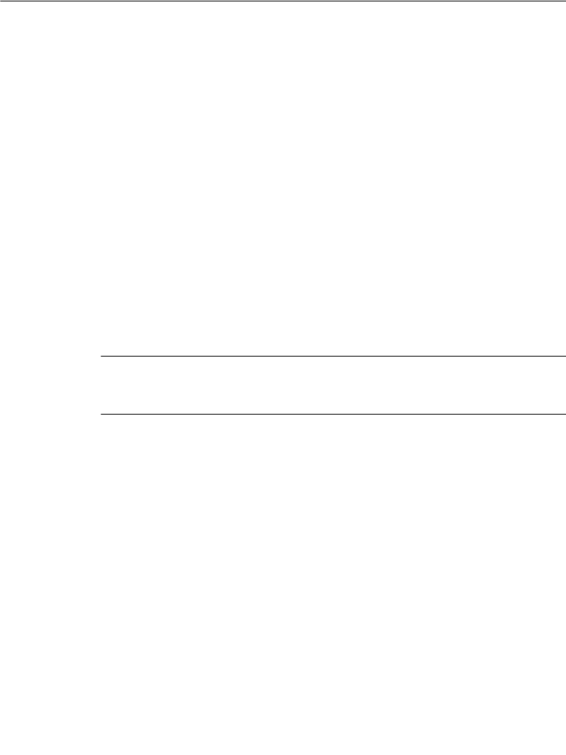
8-2 About Color
About Color
You determine the color choices for your labels by the supplies you install.
When you compose a label, the system uses the ribbon supply installed in your
printer to determine which colors you can select for print colors, and the tape
supply to determine the background color. The information your system needs is
stored in the memory cell flag located on each ribbon and tape cartridge. The
system reads that information each time you:
zTurn on the system
zRetrieve a file stored in memory
zChange the tape or ribbon
zPrint any label
When you print a label, the system checks the contents and size of the label against
what it knows about the ribbon that is installed. If the job requires that you install
different or additional ribbons or tapes, the system prompts you to do so at the
appropriate time in the print process.
The system also checks the label background color against the installed tape color,
and may display a warning message if there is a discrepancy.
Hint! Be sure to see the Checking Supplies section in the Printing chapter,
beginning on page 11-10, for important information about how your
ribbon and tape choices affect the way your label prints.
Ribbon color
The ribbon you install determines the color choices you have for the objects you
place in your labels. Depending on your system, you can use several types of
ribbon:
Continuous single color ribbon, which contains one color throughout the
length of the entire ribbon. All three systems can use this type ribbon. This
type ribbon is sometimes referred to as “monochrome,” because it contains a
single color.
Paneled ribbon, which has two or four colors and always includes black. The
panels are arranged sequentially in 8 inch (203 mm) or 16 inch (406 mm)
lengths on each ribbon. The printer makes multiple passes over the tape to
print those colors on the label. Only the Multicolor and the Color & Cut
systems can use paneled ribbons.

Applying Color 8-3
CYMK paneled ribbon, which has cyan, yellow, magenta, and black panels
of 8 inches (203 mm) or 16 inches (406 mm). The printer uses all four color
panels to produce 23 blended colors on your labels. Only the Multicolor and
the Color & Cut systems can use CYMK ribbons.
Continuous process color ribbon, which contains cyan, yellow, magenta, and
black in a continuous ribbon and produces blended colors. Only the Multicolor
and the Color & Cut systems can use Continuous process color ribbons.
Depending on the ribbon installed, you can produce several types of color on your
printed labels:
Single color uses a continuous single color ribbon or one of the colors in a
paneled ribbon:
• With the Monocolor system, the system prints the entire label with the
installed monochrome ribbon.
• With the Multicolor and Color & Cut systems, the system prompts you for
the correct color ribbons, if you applied multiple colors when composing
your label.
Note: If all objects on the label are the same color, the system prints with the
installed monocolor ribbon, even if the color of the ribbon does not match
the color of the objects.
Spot color uses solid color ribbons, either paneled ribbons or continuous
single color ribbons that you must swap in when required. Spot colors print
without blending with other colors to achieve the desired output color.
Blended color uses the cyan, magenta, yellow, and black CYMK ribbons,
either paneled or continuous, that print in combination with each other to
achieve 23 pre-defined blended colors, including black. This is sometimes
referred to as full color printing.
8-4 About Color
In summary, your system and the installed ribbon together determine what kind of
color you can apply to objects when composing a label:
Tape color
The tape you have installed in your system determines the background color of
your labels. The system assumes that the tape color you install is the background
color you want to use on your label.
Some template-driven applications may require specific background colors for the
template you choose. If you have the wrong color tape installed for that template, at
print time the system prompts you to install the correct color tape.
System: Produces:
Monocolor model zsingle color, using continuous color ribbons or
one of the colors in a paneled ribbon
Multicolor model zsingle color, using continuous color ribbons or
one of the colors in a paneled ribbon
zmultiple spot colors, using paneled or
continuous single color ribbons
zblended color, using CYMK paneled ribbons or
continuous process color ribbons
Color & Cut model zsingle color, using continuous color ribbons or
one of the colors in a paneled ribbon
zmultiple spot colors, using paneled or
continuous single color ribbons
zblended color, using CYMK paneled ribbons or
continuous process color ribbons
Applying Color 8-5
Applying Color to Objects
Your color choices and how you can use color for objects in your labels depend on
your system and the ribbon you have installed.
zWith the Monocolor system, you can change the color of an object from the
print color to the background color, and vice-versa. This means, for example,
that if you have a red ribbon with a white tape supply, you can:
Print the label with the object in red with a white background
or
Print the label with the object in white with a red background.
Hint! You can also inadvertently make an object disappear, if you make it the
same color as the background.
zWith the Multicolor system, you can print monochrome, spot color, and full
color.
zWith the Color & Cut system, you can print monochrome, spot color, and full
color.
With all systems, to apply color to an object, you select the object and use
whichever of these three methods is available:
zPress <Object Color> on the keyboard.
zChoose Object Color on the toolbar, shown here:
zSelect the Color option, which appears on the Font screen that is displayed
when you press the Font button on the Enter Text screen.
In all three cases, you’ll see Object Color screen.
About the Object Color screen
When you compose a label, the drawing color defaults to black regardless of the
color or type of ribbon you currently have installed. You can select a color for the
object on the Object Color screen, which provides different options depending on
your system and the ribbon supplies you have installed.
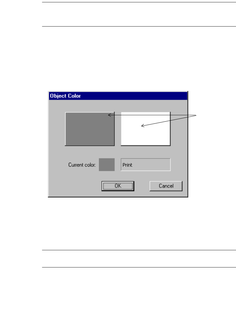
8-6 Applying Color to Objects
Note: You may not change the colors of a multi-color graphic object supplied by
the system. You may, however, change the entire color of a single-color
graphic.
The Object Color screen differs according to your system and the ribbon you have
installed.
Choosing color on the Monocolor system
When you have the Monocolor system, if you select an object and choose the Color
option, the Object Color screen displays, similar to the one shown here:
Figure 8-1. The Object Color screen for the Monocolor system.
In Figure 8-1, the installed ribbon is a continuous color ribbon, and the installed
tape is white.
When you click on one of the color boxes, the Current color field displays a
sample of that color, and tells you what part of your label will print in that color.
Note: Tape always appears as a white background while the ribbon appears as
black on the screen display.
Color boxes
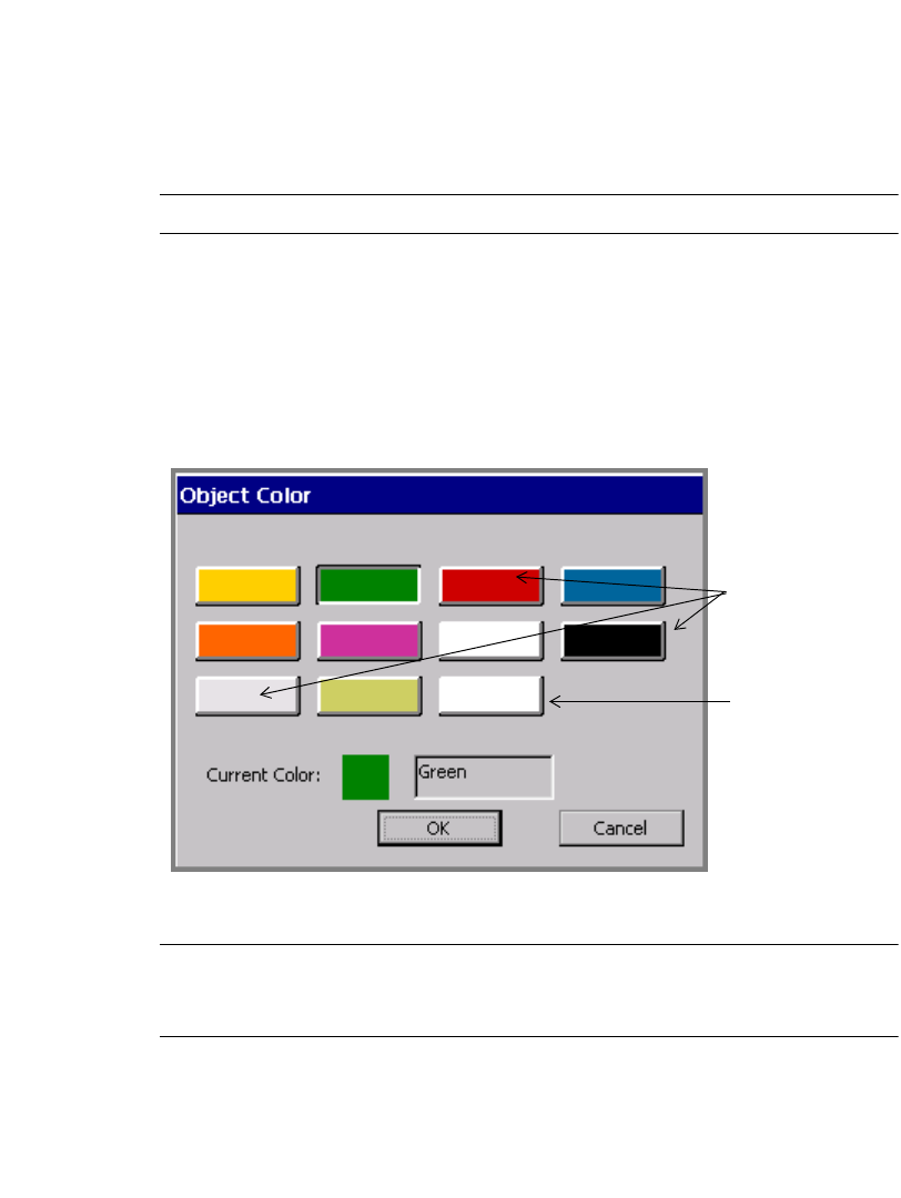
Applying Color 8-7
Choosing color on the Multicolor and Color & Cut
systems
If you have the Multicolor or the Color & Cut system, the options offered on the
Object Color screen also depend on the type of ribbon installed at the time you
choose the Color option.
Note: The Autocut function cannot be applied in multicolor mode.
If you swap in a different ribbon during construction of the label or while editing it,
the Object Color screen changes according to the characteristics of the new ribbon,
as described in the following sections.
With a continuous color ribbon installed
The Object Color screen looks similar to Figure 8-2 when you have a continuous
color ribbon installed on your Multicolor or Color & Cut system:
Figure 8-2. Object Color screen, continuous color ribbon on the Color & Cut system.
Hint! Use this screen to set object colors at composition time without having to
swap in each ribbon. You won’t have to swap in the different ribbons until
you print the label.
The color boxes
show the colors
available in
continuous color
ribbons.
This box shows
the background
color (the tape
installed).
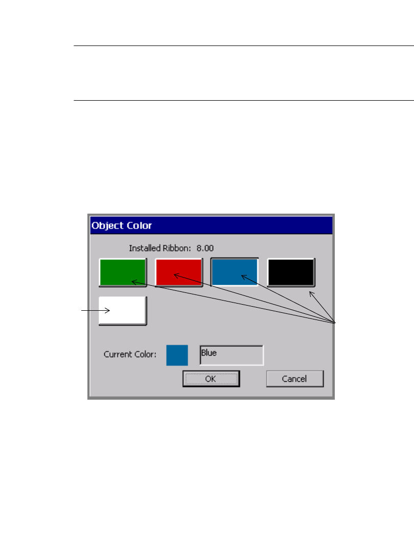
8-8 Applying Color to Objects
The color boxes show the continuous color ribbons available (including the
currently installed ribbon). The Current color field shows the color of the
currently selected object, or if there is no object selected, the current print color.
Important! If you are using a new supply color that you have not yet named,
it will not show on this screen. See Naming supply colors on
page 5-9 for instructions on how to make your system recognize
new colors.
The final box in the series in Figure 8-2 shows the background color. When you
choose that box, the Current Color text changes to “Background.”
See Ribbon and color choices on page 11-15 for more information.
With a paneled ribbon installed
The Object Color screen looks similar to this when you have a paneled ribbon
installed:
Figure 8-3. The Object Color screen with paneled ribbon on the Color & Cut systems.
This screen shows you the colors available on the paneled ribbon you have
installed. Choose a box to select a color for the object you have selected. The
Current color field shows the color of the currently selected object, or if no object
is selected, the print color.
The final box in the series shows the color of the currently installed tape. If you
choose that box, the Current Color text changes to “Background.”
The color boxes
show the panel
colors of the
installed panele
d
ribbon.
The background
color (the color
of the installed
tape)
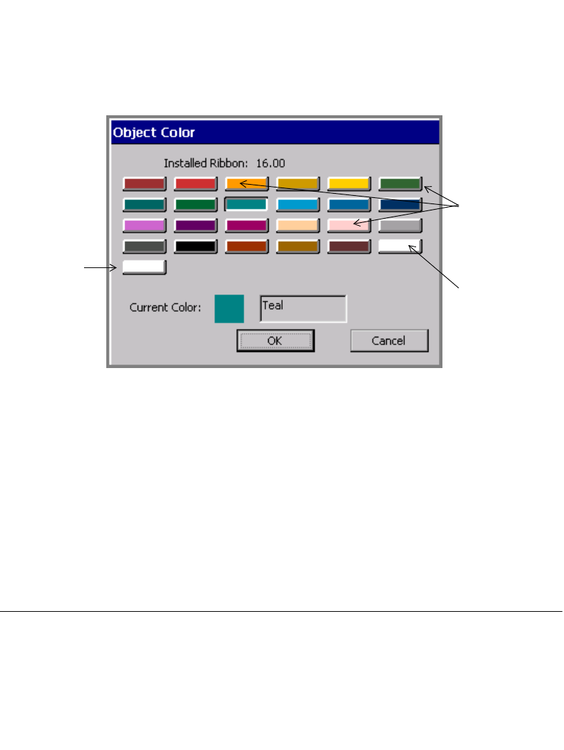
Applying Color 8-9
The panel length of the currently installed ribbon is shown at the top of the screen
in the Installed Ribbon field. See Checking Length on page 11-12 for
information about how panel length affects your label length.
With a CYMK ribbon installed
The Object Color screen looks like this when you have a CYMK ribbon installed:
Figure 8-4. The Object Color screen with CYMK ribbon on the Color & Cut systems.
You can choose any of the colors on this screen for your selected object, except the
final box in the series, which is the background (or tape supply) color. The Current
color: field shows you the color and the name of the color you select, unless you
choose the background color. In that case, the text indicates “Background.” The
Installed ribbon field shows the panel length for the ribbon installed your
machine.
See Checking Length on page 11-12 for information about how panel length
affects your label length.
Printing Color
See CHAPTER 11: Printing, beginning on page 11-1, for complete information
on printing your labels.
The 23 color
boxes show the
blended colors
this ribbon can
produce.
The
background
color The current
media (tape)
color

8-10 Printing Color

Working with Files 9-1
This chapter explains how to store labels you create on your system so you can
access them another time. You store them as files, and you organize the files in file
groups. Topics in this chapter include:
About Files and File Groups
Saving Labels as Files
Managing Files
Printing Files
Transferring Files
Using My Templates
CHAPTER 9 Working with Files
9-2 About Files and File Groups
About Files and File Groups
When you store a label, you name it and save it, and it becomes a file on which you
can then perform several operations. (You can also save multiple labels in a single
file, such as when you create a label set or when you create labels with variable
text. Refer to Creating Sets of Labels on page 6-21 for information on label sets,
and to Adding variable text objects on page 7-10 for information on variable text
labels.)
When you save a file, the system prompts you to put it into a file group. Ideally,
your file groups contain labels with similar characteristics, such as subject,
orientation, or size, but you can group any files together in a file group.
Hint! If you plan to print all the files in the file group in the same print job, it’s
best if the files are set in the same orientation and use the same supplies.
See Printing labels in a file group on page 11-7 for more specific
information.
The system saves the files in file groups in an internal storage area or on a memory
card attached to your system. (You can also save file groups to a PC. See
CHAPTER 12: Connecting to a PC, beginning on page 12-1, for more
information.)
Once you save a label as a file in a file group, you can:
zOpen it
zAdd objects to it or remove objects from it
zPrint it by itself or print its entire file group at the same time
zCreate a new file of the same type
zDelete it

Working with Files 9-3
Saving Labels as Files
Every time you create a Custom label or a pre-designed template label, you have
the option to save it as a file and to put it in a file group, so you can access it later.
Your label file is like a paper document you put in your file cabinet, and file groups
are like the file folders in which you put your papers. You can organize similar
label files into file groups in the same way as you organize similar paper files into
file folders.
When you have an open, unsaved label displayed in the Editor window, there are
two ways to save labels as files:
zBy using the <Menu> key and following the prompts
zBy using the <File Option> key and following the prompts.
There are two places you can save files as well:
zIn your system’s internal memory
zOn a compact flash memory card attached to your system. (See Installing a
compact flash memory card on page 2-13 for information.)
Hint! You can also save files to a PC if you are connected to one. See See
CHAPTER 12: Connecting to a PC, beginning on page 12-1, for
instructions.
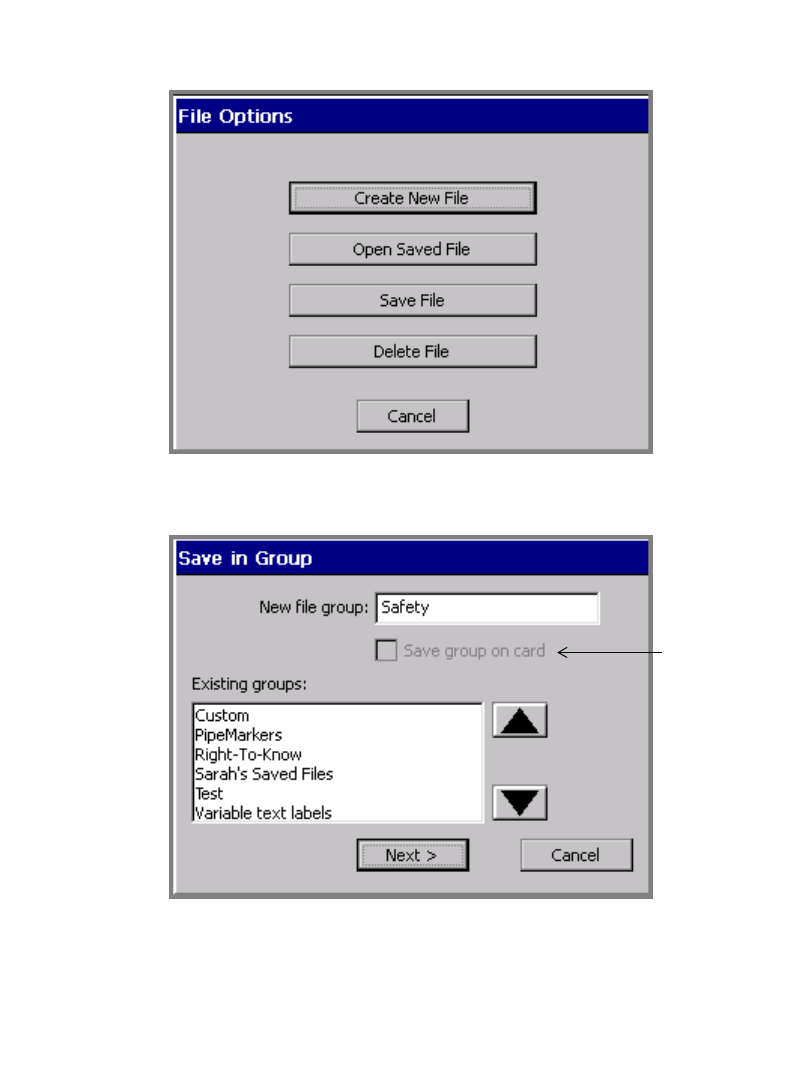
9-4 Saving Labels as Files
To save a label as a file in internal memory
1. With the unsaved label displayed in the Editor window, press <File Options>.
You’ll see the File Options screen:
Figure 9-1. The File Options screen.
1. Choose Save File. You’ll see the Save in Group screen:
Disabled unless
memory card is
attached to
your system.
Figure 9-2. The Save in Group screen.
Working with Files 9-5
2. The default group displayed in the New file group field is the name of the
application you used to create the file. You have several choices for the New file
group field:
• Accept the default as the name for the group
• Enter a new name.
• Choose a name from the list of existing groups.
Hint! If your label doesn’t fit into any particular category, you may find it useful
to create a general group like “My Saved Files.”
3. Select Next when you have completed the Save in Group screen. (If you
choose Cancel, the Save process is interrupted and you are returned to the
Editor window.)
You’ll see the Save File screen:.
The preview area
displays thumb-
nails of the
group’s saved
files as you scroll
through the Saved
files list.
Figure 9-3. The Save File screen.
If you have previously saved files in that File group, you’ll see them listed in
the Saved files box.
The system displays a thumbnail view of the label highlighted on the Saved
files list.
4. Type a name for your new file in the File name field.
Hint! You can select a name for your new file from the Saved files list instead of
typing a new name, but be careful not to overwrite an existing label you
9-6 Saving Labels as Files
want to keep. If you respond Ye s when the system asks you if you really
want to replace the old file, the system discards the old saved label and
puts the new saved label in its place. You cannot recover the discarded
file.
5. Choose OK when you have named your file. The system saves the new file and
filename.
• If you choose Cancel, no file is created and you’ll see the unsaved file on
the Editor window.
• If you choose Back, you’ll see the Save in Group screen again, where you
can change the Group name or choose a different group.
To save a file to a memory card
If your system has a compact flash memory card installed, you can save the file and
its file group to the memory card. (See Installing a compact flash memory
card on page 2-13 for information about memory cards.)
1. With the unsaved label displayed in the Editor window, press <File Options>.
You’ll see the File Options screen (Figure 9-1).
2. Choose Save File. You’ll see the Save in Group screen:
Enabled when
memory card is
attached to your
system.
Figure 9-4. The Save in Group screen with memory card.
3. Enable the Save group on card option. When you complete the file saving
procedure, the system will save the entire file group to the memory card.

Working with Files 9-7
Note that existing file groups you previously saved on memory cards are
designated with (card) after their names.
4. Choose OK. You’ll see the Save File screen (Figure 9-3).
5. Enter a name for the file in the File name field.
6. Choose OK. The system saves the file and the file group to the memory card.
Managing Files
You can open, edit, delete, or save the files you create to new groups.
Hint! You can also print all or some of the files in a file group at the same time.
See Printing labels in a file group on page 11-7
Opening saved label files
You can open files from the Main Menu screen or from within the Editor window.
Once the file is open and the label is displayed in the Editor window, you can edit
it, print it, add new labels, and do anything else you can do to a newly-created file.
9-8 Managing Files
Note: When you open a saved file, you should be aware that the label in the file
may not match the size and color of currently installed tape. When that is
the case, the system displays the label with the characteristics of the
current tape. You may still proceed to make changes, print, or perform any
operations you can perform in the Editor window.
To open a file from the Main Menu screen
1. Choose the Saved Files option. You’ll see the File Groups screen, which lists
all file groups you have previously saved:
Groups saved
on attached
memory card
Figure 9-5. The File Groups screen with memory card.
If you have a memory card attached, the File Groups screen lists the file groups
saved on the card also. Those groups are listed with (card) shown after the
group name.
If you have no files saved yet, the Group name list is blank, and the Next
button is disabled.
2. Choose the group in which you stored your file.
3. Press Next. (If you change your mind, press Cancel to return to the Main
Menu screen.)
Working with Files 9-9
4. You’ll see the Open File screen:
Figure 9-6. The Open File screen.
5. Select the file you want to open on the Select file list.
6. Press OK to open the file. You’ll see the label (or the first label if the file
contains a series of labels) from the file you opened displayed in the Editor
window.
Alternatively, you can:
• Choose Cancel to cancel the operation and return to the Main Menu screen.
• Chose Back to return to the previous screen.
To open a file from the Editor window
1. While in the Editor window, press the <File Options> key. You’ll see the File
Options screen shown in Figure 9-1 on page 9-4.
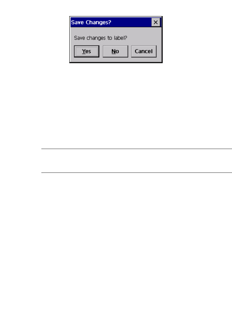
9-10 Managing Files
2. Choose Open Saved File. If you have an unsaved label currently displayed, the
system prompts you to save it or to discard it:
Figure 9-7. The Save Changes prompt.
(If you choose Ye s , you’ll be prompted for File Group and File Name, as
described in Saving Labels as Files on page 9-3.)
3. After you deal with any unsaved labels, you’ll see the File Groups screen,
shown in Figure 9-5 on page 9-8.
4. Choose the File Group in which the label file is stored, then choose OK. You’ll
see the Open File screen, shown in Figure 9-6 on page 9-9.
5. Choose the file you want to open, and press OK. You’ll see the label from the
file you opened displayed in the Editor window.
Hint! You can also open a saved file from the Create New Label screen that
displays when you launch an option from the Main Menu screen. For an
example, see Figure 6-2 on page 6-3.
Editing files
Open the saved label file as described in Opening saved label files on page 9-7.
Once the label is displayed in the Editor window, you can make changes, then
print it or re-save it.
See Opening and editing an object on page 7-31 and Changing Label
Properties on page 6-27 for information about editing labels.
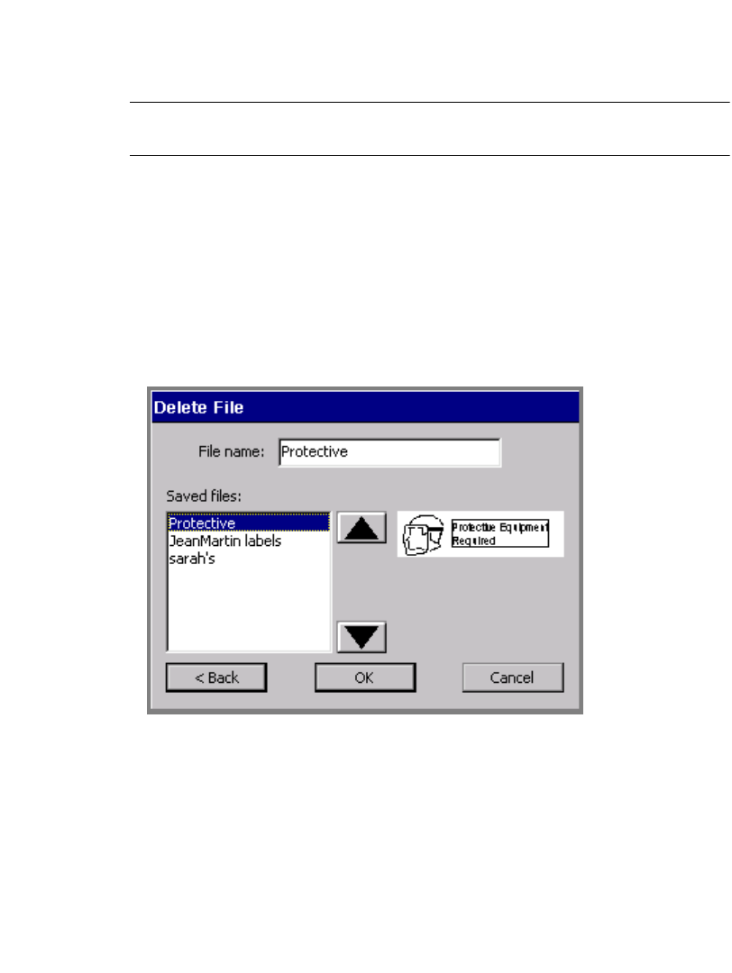
Working with Files 9-11
Deleting files
When you delete a label file, the system deletes the file either from the internal
storage area or from the memory card, if you have one installed.
Note: Use caution when deleting files. Once you delete a file, you cannot
recover it.
To delete a label file
1. Press <File Options> on the keyboard.
2. On the File Options screen (shown in Figure 9-1 on page 9-4), choose Delete
File. You’ll see the File Groups screen (Figure 9-5 on page 9-8).
3. From the Group name list, select the File group that contains the file you want
to delete.
4. Choose Next. You’ll see the Delete File screen:
Figure 9-8. The Delete File screen.
5. Select a file from the Saved files list, then choose OK. The system deletes the
file you selected, then returns you to the Editor window.
9-12 Printing Files
Printing Files
You can print a single file or you can print an entire file group. For instructions, see
Printing a single label on page 11-4, Printing labels in a label set on page 11-6,
and Printing labels in a file group on page 11-7.
Transferring Files
You can transfer templates and other kinds of files from a PC to your standalone
system. This is useful in instances where you need to be able to use a file that
normally resides on your PC on your printer when it is not connected to a PC.
Important! We recommend that only experienced PC users attempt file
transfers from a PC to the standalone printer. The underlying file
structures are complex and you risk losing data if your attempt is
unsuccessful.
See Transferring Files from a PC on page 12-8 for information.
Using My Templates
The My Templates option on the Main Menu screen appears only if you or
someone in your organization has previously downloaded, copied, or moved a file
to your system using the File Management Utility. (The File Management Utility is
the software your system uses to communicate with your PC, when you have one
connected.) Otherwise, you will not see it on the Main Menu.
See CHAPTER 12: Connecting to a PC, beginning on page 12-1 for information
about File Management Utility.
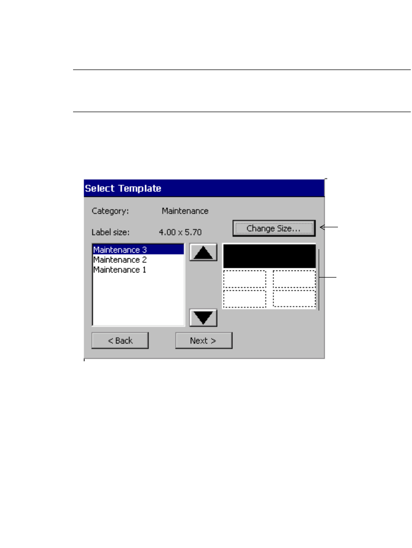
Working with Files 9-13
Accessing template files
You can access template files you created, or that you or someone in your
organization has downloaded to your system, through My Templates. You may not
access the template files supplied with the applications on your system.
Note: When you download template files to your system for the first time, you
must re-start your system before you can use the My Templates feature.
See Managing files and folders on a PC on page 12-10 for instructions.
To access My Template files
1. Choose My Templates from the Main Menu screen.The Select Template
screen displays:
The preview
area displays
thumb-nails of
the templates
as you scroll
through the
list.
Enabled only
if template is
scalable
Figure 9-9. The Select Template screen.
2. Choose a template from the list of template files. Note that the preview area
displays thumbnails of the selected file.
3. Choose Next to begin the template prompt sequence. Complete the prompts as
instructed to make the label.

9-14 Using My Templates
Changing My Template label size
Use the Change Size button on the Select Template screen (Figure 9-9) to
customize the size of the label you are creating.
Note: This option is applicable only if the template is scalable.
Follow the instructions in the section Changing Labels on page 6-24.
10-1
If you have the Color & Cut system, read this chapter for information about the
cut out functions.
(If you have the Monocolor system or the Multicolor system, the information in this
chapter is not applicable to your system.)
This chapter defines and describes the capabilities of the plotter cutter included in
your system. Topics include:
About Cutting
Creating Cut Out Objects
Cutting Around Objects
Cutting Around Label Frames
Calibrating the Cutter
Important! See Appendix B: Cutter Maintenance for information about
adjusting and replacing the plotter cutter stylus, and for cleaning
the plotter cutter stylus.
CHAPTER 10 Working with Cut-outs
10-2 About Cutting
About Cutting
The term “cut” is used in multiple ways in the Color & Cut system. To help you
avoid confusion, the terms as used are defined here:
The Color & Cut system is equipped with a plotter cutter, which means the system
can:
zCut out objects that you have designated as a Cut out Object on the Insert
Object screen. The cutter cuts out the actual shape of the object.
Cut The standard Microsoft Windows “Cut” command, which means
removing an object from its current location and temporarily
storing it for later retrieval. (This term is not used in this chapter.)
Cut out The action of cutting out objects or text using the plotter cutter
inside your printer. The cutter follows the shape of the object or
text. An object that is cut out cannot be printed.
Cut out
frame
The action of cutting out a label that has been framed. You apply
a frame to a label using the Label Properties options (See Adding
a label frame - 6-31). The plotter cutter cuts around the outside
edge of the frame line.
Also, when you apply the Supply Saver option or are printing
multiple copies, the system performs this action automatically.
(See Supply saver option - 11-21 for more information.)
Cut
bounding
box
The action of cutting around an object that is enclosed by a cut
bounding box. The plotter cutter cuts the box shape, not the shape
of the object inside it.
Print To produce or to output the contents of the current file. For the
Color & Cut system, the labels in a file may include both printed
objects and cut out objects, even though print objects may only be
printed and cut out objects may only be cut out.
Shear A straight cut through the tape and liner that separates the output
label from the remaining tape supply.
Weeding A cut around the outside of a cut text object.
Working with Cut-outs 10-3
Important! Objects cannot be both print objects and cut out objects at the
same time. See Adding cut out objects - 10-4 for details.
zCut out around a cut bounding box you can create for some print objects. A cut
bounding box is a border you can set around objects that you want to print AND
cut. See To apply a cut bounding box to an object - 10-8 for instructions.
zCut out around a frame you add to a label. See To cut around a label frame -
10-10 for instructions.
zPerform weeding on cut out objects. See To perform text weeding - 10-6.
Table 10-1 shows your cutting options, listed by item:
TABLE 10-1. Cut options.
(For additional information about these object types, see About Objects - 7-2.)
Creating Cut Out Objects
You create cut out objects by adding them to a label, the same way you create and
add print objects. Once you choose the Cut out object option, your other choices
are limited, however, to objects that may be cut out. See Table 10-1 for a list of
those objects
Item
Can be cut out (not
printed)
Can be printed and cut
around
Text object Yes Yes
Graphic object
•Most Adobe
Illustrator© vector
graphics
•Bitmap and vector
graphics
Yes
No
Yes
Yes
Bar code object No Yes
HotShape object Yes Yes
Label frame No Yes
10-4 Creating Cut Out Objects
Also, not all tape supplies are appropriate for cutting. If the cutter cannot use the
tape installed in your printer, the Cut out option on the Insert Object screen will
be grayed out.
Adding cut out objects
When you add objects to your label, the Insert Object screen gives you the choice
to insert a Print object or a Cut out object, as shown here:
Figure 10-1. The Insert Object screen on the Color & Cut system.
zIf you choose Print object, you may only print the object, although in some
cases, the object may be cut around. See Cutting Around Objects - 10-8 to
learn how to cut around a print object.
zIf you choose Cut out object, the object may only be cut out, and not printed.
Hint! You can change some existing print objects to cut out objects and vice-
versa, by going to the General tab on the object’s Properties screen and
choosing the appropriate option. See Changing Objects on page 7-31 for
instructions.
To create a cut out object
1. From the Editor window (shown in A sample Editor window with cut
bounding box displayed. - 10-9), choose Insert Object.
Working with Cut-outs 10-5
2. On the Insert Object screen (Figure 10-1), choose Cut out object.
3. Select the type of object you want to cut out. The type you choose determines
the screen you will see next:
Cutting out text objects
The cutter cuts out each individual character in a Text cut out object.
Hint! See Weeding cut out text objects - 10-6 to learn how to make an
additional cut around the cut out text, for ease of use when removing the
cut out characters.
To cut out text objects
1. After selecting the Cut out object option on the Insert Objects screen, choose
Text.
2. On the Enter Text screen (shown in Figure 7-3 on page 7-5), enter the
characters you want to cut out.
3. Press OK when you’re finished. You’ll see the cut out new text object on the
Editor window.
4. Choose Print to cut out the object.
If you choose: You’ll see:
Text object The Enter Text screen (Figure 7-3 on page 7-
5). You can choose from these fonts for cut out
text objects:
•Arial 65 for BRC
•Arial for BRC
•Times New Roman for BRC.
Only normal text is supported. Cut out text
may not be bolded, italicized, or underlined.
Graphic object The Graphics screen, shown in Figure 7-15
on page 7-23, with special options for cut out
graphics listed.
HotShape object The HotShapes screen, shown in Figure 7-16,
10-6 Creating Cut Out Objects
Weeding cut out text objects
Your Color & Cut system can perform weeding on cut out text objects. Weeding
makes it easier for you to strip out waste from around cut text characters.
In the weeding process, the cutter cuts a border around a cut out text object. In a
text object with multiple lines of text, each line gets its own cut out border.
To perform text weeding
1. Create a cut out text object as described in the Cutting out text objects section
above.
2. With the cut out text object displayed in the Editor window, select the object.
3. Press Object Properties or select the Object Properties tool.
4. You’ll see the Text Properties screen, General tab:
Figure 10-2. The Text Properties screen for a cut out object
5. Check the Cut bounding box option.
6. Check the Weeding option.
7. Choose OK.
8. Choose Print to cut out your label.

Working with Cut-outs 10-7
Cutting out variable text objects
You might use variable text cut out objects to create and cut out the labels you
create for names in a list of names, or to cut out a series of numbers you want to use
for marking items. (See Adding variable text objects on page 7-10 for more
information.)
To cut out variable text objects
1. After selecting the Cut out object option on the Insert Objects screen, choose
Varia ble t ext.
2. You’ll see the Data Source screen (shown in Figure 7-6 on page 7-11). Choose:
•Sequence to create Sequential labels, with variable text objects consisting
of increasing or decreasing numbers or alphabetic letters. Refer to Creating
sequential labels on page 7-11.
•Text li st to create Text list labels, with variable text objects consisting of a
list of items you create. Refer to Creating text list labels - 7-14.
3. When the creation sequence is complete and you are back in the Editor
window, choose Print to process the labels and cut out the variable text objects.
Cutting out graphic objects
Not all graphic objects may be specified as cut out objects. The system offers only
graphics suitable for cutting out when you choose the Graphics button on the
Insert Object screen, and does not allow you to specify a graphic object as a cut
out object if it is not suitable for cutting out.
To cut out graphic objects
1. After selecting the Cut out object option on the Insert Objects screen, choose
Graphic.
2. You’ll see the Graphics Categories screen (shown in Figure 7-14 on page 7-
22). Select a category and choose OK.
3. You’ll see the Graphics screen (shown in Figure 7-15 on page 7-23.) Select a
graphic and choose OK.
4. When the creation sequence is complete, choose Print, which processes the
labels and cuts out the graphic objects.
10-8 Cutting Around Objects
Cutting out HotShape objects
HotShapes are especially suited for cutting out. You can cut out stars, circles,
arrows, and other shapes. See Adding HotShapes on page 7-24 for information
about the HotShapes available on your system.
To cut out HotShapes
1. After selecting the Cut out object option on the Insert Objects screen
(Figure 10-1 on page 10-4), choose HotShapes.
2. You’ll see the HotShapes screen. Select the HotShape object you want to add
as a cut out.
3. Your HotShape displays on the Editor window. Choose Print to process the
label and cut out the HotShape.
Cutting Around Objects
While objects may not be both print and cut out objects at the same time, there is a
way to cut around some print objects. You can apply a cut bounding box to a print
object, which is like adding an invisible border around the object. The system then
cuts around the cut bounding box that encloses your print object. You can apply cut
bounding boxes to all types of print objects: text, graphics, HotShapes, and even
bar codes.
Hint! You can also apply cut bounding boxes to cut out objects, to make it easier
to strip the waste material from around the cut out object.
To apply a cut bounding box to an object
1. Create your label in the normal way, adding objects as described in Adding
Objects on page 7-3.
2. With your label displayed on the Editor window, select the object to which you
want to apply a cut bounding box. If you have many layered objects on the
screen, use <Tab> to cycle through the objects to find the one you want to use.
(For more information, see Selecting a layered object - 7-26.)
3. Select the Object Properties tool or press the Object Properties key.
Working with Cut-outs 10-9
You’ll see the Properties screen appropriate for the type of object you selected.
The values in the fields on the Properties screen reflect the current properties
of the object selected.
Check the Cut bounding box option on the General tab, and choose OK. Your
label displays again in the Editor window, with the cut bounding box indicated
around the chosen object.
Figure 10-3. A sample Editor window with cut bounding box
displayed.
When you print your label, the cutter cuts around the borders of the cut boundary
box.
Minimum cut size
When you are ready to print, if any label in the print job contains cut text or cut out
objects that are smaller than the minimum recommended size, the Cut Items Too
Small screen appears:
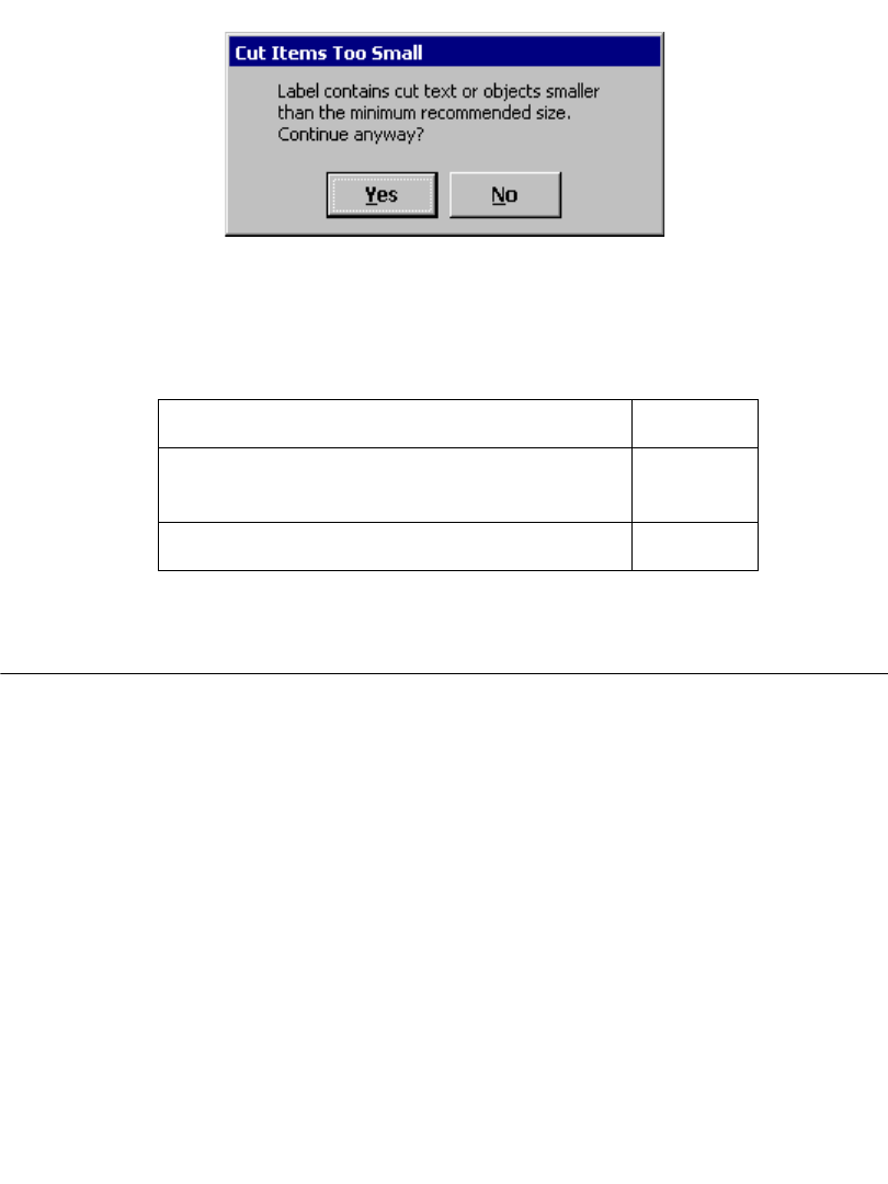
10-10Cutting Around Label Frames
Figure 10-4. Minimum cut size message.
You can select Yes to continue printing, or No to cancel the job at the offending
label. (The printing of all subsequent labels will also be canceled.)
The minimum recommended sizes for cutting are:
Cutting Around Label Frames
You can add a frame around the edge of a label in the shape of a rectangle or a
rectangle with rounded corners. If you have the Color & Cut system, you can also
choose to cut the label around the frame boundaries.
To cut around a label frame
1. After you have created your label and it is displayed in the Editor window,
press the Label Properties key. You’ll see the Label Properties screen, which
has a Size tab and a Frame tab.
Cut text ½”
Simple shapes (HotShapes only: rectangle, circle,
rounded rectangle, arrow, ellipse, and star)
¼”
Cut out graphics ½”
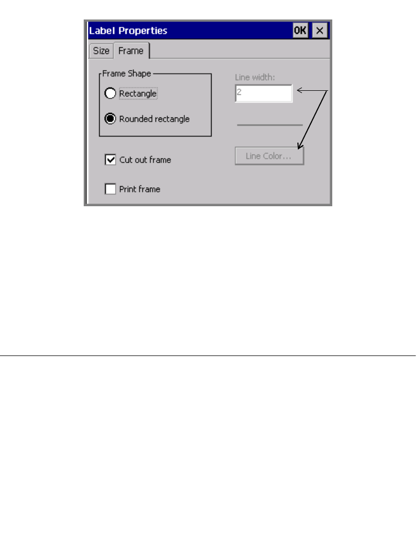
Working with Cut-outs 10-11
2. Choose the Frame tab:
The Line
width and the
Line Color
options are
not available
if Cut out
frame is
enabled.
Figure 10-5. The Label Properties screen, Frame tab., on the
Color & Cut system.
3. Select a Frame shape option: Rectangle or Rounded rectangle.
4. Check the Cut out frame option.
5. When you finish setting Label Properties options, click OK. See Adding a
label frame - 6-31 for detailed information about the Label Properties options.
Calibrating the Cutter
If your cuts are not aligned correctly, you can adjust the plotter cutter calibration
values previously set at the factory. You begin by using the Setup option on the
Main Menu screen to calibrate the cutter.
Setting cutter calibration values
When you enter values in the Cutter Calibration fields, the values must be positive
or negative whole numbers. Each increment of the number adjusts the cut made by
.001 inch. For instance:
10-12Calibrating the Cutter
1 sets a positive change of .001 inch (.0025 mm)
-1 sets a negative change of .001 inch (.0025 mm)
2 sets a positive change of .002 inch (.005 mm)
-2 sets a negative change of .002 inches (.005 mm)
Where the change occurs depends upon the field you set:
In the Horizontal(x) field:
• Positive values adjust the cutter toward the machine.
• Negative values adjust the cutter toward the leading edge of the tape.
In the Vertical(y) field:
• Positive values adjust the cutter toward the bottom edge of the tape.
• Negative values adjust the cutter toward the top edge of the tape.
Figure 10-6 may help show how your calibrations affect your labels. The
intersection of the x,y axes represents the center point of your label:
Figure 10-6. Cutter calibration axes
Leading edge
Top edge
Machine
Bottom edge
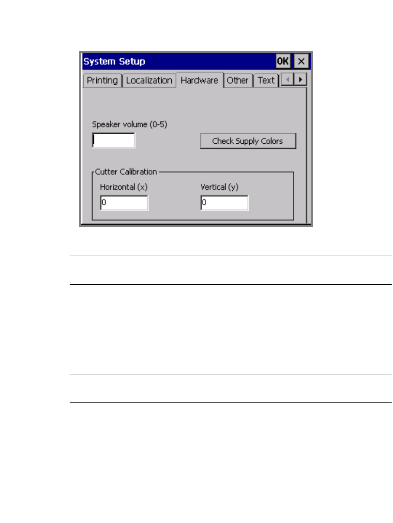
Working with Cut-outs 10-13
To calibrate the cutter
1. On the Main Menu screen, select Setup.
2. On the System Setup screen, choose the Hardware tab:
Figure 10-7. The System Setup Hardware tab
Hint! Write down the values (which were individually set at the factory) before
you change them, in case you want to restore the defaults.
3. Enter a value in the Horizontal (x) field. The value must be a positive or
negative whole number.
4. Enter a value in the Vertical (y) field. The value must be a positive or negative
whole number.
5. Choose OK.
Note: You must close down and restart your printer for new settings to take
effect.

10-14Calibrating the Cutter
Restoring default cutter calibration settings
To restore factory set calibration settings, you must re-enter the original values on
the Hardware tab. Your system ships with a label inside the printer applied at the
factory that lists those values.
To restore default calibration settings
1. Locate the factory-installed label on your machine.
2. On the Main Menu screen, select Setup.
3. On the System Setup screen, choose the Hardware tab.
4. Enter the original value in the Horizontal (x) field.
5. Enter the original value in the Vertical (y) field.
6. Choose OK.

11-2 Printing Labels
Printing Labels
Most of the time, printing a label is a very simple process. When you finish creating
a label or have opened a saved label, with the label displayed in the Editor
window, you press the Print key or choose the Print tool (shown here at the left).
You may print a single label or multiple copies of a single label, or all labels in a
label set, including variable text labels. You can also use Advanced print features to
print partial label sets or file groups.
The processes described here assume that the supplies installed in your printer
match the label you want to print. See Checking Supplies on page 11-10 for
information about how the system prompts for supplies when it processes jobs, and
what you do to meet the requirements.
About pages
You’ll see references to pages in the print discussions that follow. It’s helpful to
understand that a page is not the same as a label, especially if you print multiple
small labels or entire file groups. Information about both those cases follow in the
sections in this chapter. (For the majority of print jobs, one page contains one
label.)
A page is the area between the leading edge of the tape (where the label starts),
and the shear cut. A page can contain one or more than one label, and the
minimum size for a page is two inches or 51 mm. See Figure 11-1 and Figure 11-2
for illustrations of pages.
Hint! The shear cut is the straight cut your system makes through the tape and
liner. This cut separates the output label from the remaining tape supply.
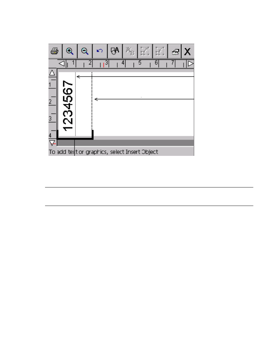
Printing 11-3
Single label on a page
For most print jobs, one page contains one label. A label may or may not use up an
entire page. For example, if the label you create is shorter than the two inch
(51mm) minimum page length, the label and page print like this:
Figure 11-1. Sample short label.
Note: The label length and shear lines in Figure 11-1 are shown to illustrate the
concepts discussed here. Those lines will not display on your screen.
Since two inches (51 mm) is the minimum supply length the system permits for
reliable delivery of a label, the shear cut is at two inches, although your label is
only one inch long. (You will need to trim the excess supply by hand.) See
Checking Length on page 11-12 for more information.
Multiple labels on a page
You may print multiple labels on a single page when the Supply saver option on
the Printing tab of either the System Setup screen or the Preferences screen is
enabled. (See Supply saver option on page 11-21 for more information.)
System
shears here
A single page
Your actual
label length
11-4 Printing Labels
For example, if you submitted a print job for five copies of this label, and the
Supply saver option is ON, the output looks like this:
Figure 11-2. Sample labels with Supply saver option enabled.
Printing a single label
Printing a single label is a simple two-step process.
1. With the label you want to print displayed in the Editor window, press Print or
choose the Print tool on the toolbar. You’ll see the Print screen:
Figure 11-3. The Print screen.
First page of print job Final page of print job
Printing 11-5
2. Choose OK. You’ll see the Preparing to Print screen while the printer
processes your label.
Figure 11-4. The Preparing to Print screen.
The printer prints, shears, and delivers your label.
Note: If any label in the print job contains cut text or cut out objects that are
smaller than the minimum recommended size, the Cut Items Too Small
screen appears. You have the option of continuing to print the label or
canceling the print job. (See Minimum cut size on page 10-9.)
Printing multiple copies of a single label
This process requires a single additional step:
1. With the label you want to print displayed in the Editor window, press Print .
You’ll see the Print screen (Figure 11-3).
2. Enter the number of copies of the label you want to print in the Copies field.
3. Choose OK. You’ll see the Preparing to Print screen (Figure 11-4), which
tracks the system’s progress as it processes each of the copies.
Note: If the Supply saver option is set to ON in the Printing tab screen, the total
number of labels shown in the Label field may look incorrect. This is
because the printer is counting the total number of pages in the job instead
of the number of labels, and it may be possible to fit more than one label

11-6 Printing Labels
on a page. See About pages on page 11-2 and Supply saver option on
page 11-21 for more information.
Printing labels in a label set
When you know in advance that you want to print a group of labels all at the same
time, you can create a label set. The section Creating Sets of Labels on page 6-22
tells you how to create label sets. (Be sure to note the guidelines to follow when
creating the set to assure the print job will go smoothly.)
The following procedures describe how to print a set of labels or part of a set of
labels.
To print a label set
1. When the label set is complete (see Creating Sets of Labels on page 6-22),
choose Print . The Print screen displays, as shown in Figure 11-3.
The default setting of 1 in the Copies field means that the printer will print one
copy of each label in the set. You can make multiple copies of each label in the
set by changing this number.
2. Choose OK on the Print screen to start the print job. You’ll see the Preparing
to Print screen (Figure 11-4), which tracks the system’s progress as it processes
each of the labels in the set.
To print a subset of a label set
Use this procedure when you do not want to print all labels in a label set.
1. When the label set is complete (see Creating Sets of Labels on page 6-22), or
you have opened a file containing a label set, choose Print . The Print screen
displays, as shown in Figure 11-3.
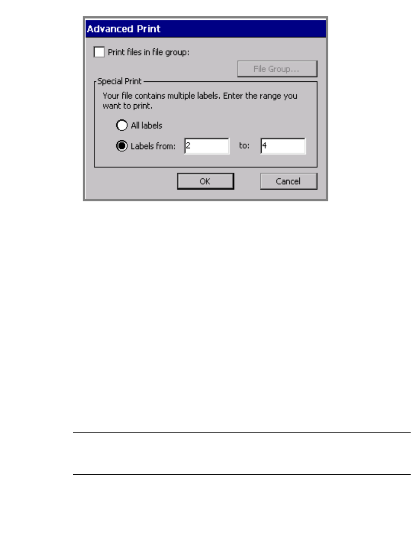
Printing 11-7
2. Choose the Advanced button. You’ll see the Advanced Print screen:
Figure 11-5. The Advanced Print screen for label sets.
3. In the Labels from field, enter the number of the first label in the set you want
to print. In the to: field, enter the number of the final label you want to print.
4. Choose OK. You’ll see the Print screen (Figure 11-3) again.
5. Choose OK on the Print screen to start the print job. You’ll see the Preparing
to Print screen (Figure 11-4), which tracks the system’s progress as it processes
the labels in the set you chose to print.
Printing labels in a file group
When you save labels as files, the system automatically prompts you to classify
them into file groups. One of the advantages of saving similar files into the same
file group is that you can save time by printing all label files in the group at the
same time. You print file groups using the Advanced features available from the
Print screen.
Hint! If you plan to print all the files in a file group in the same print job, for best
results, set the labels in the files in the same orientation, and use the same
ribbon and tape supplies.
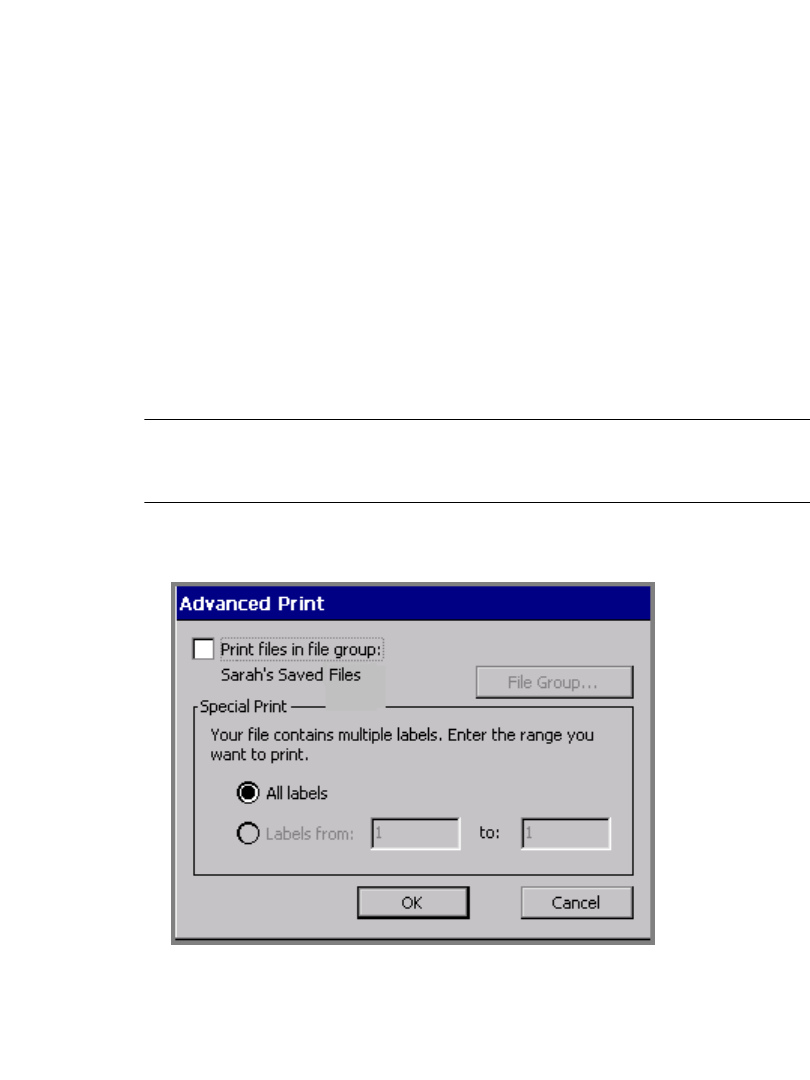
11-8 Printing Labels
Note that some restrictions apply when you print file groups:
zYou may not choose a range of files to print when printing a file group. You
must print all files in a file group, or only a single file from the group.
zDo not mix label application types within file groups. Labels created using the
QuickText, Pipe Marker, and Right-to-Know applications will not print with the
file group if labels from other applications are included in that group. You may
still print those labels individually, of course.
zFor best results, do not plan to swap paneled and continuous color ribbons
within the same print job.
To print labels in a file group
1. With any file from the group you want to print open in the Editor window,
press Print. You’ll see the Print screen (Figure 11-3).
2. On the Print screen, enter the number of copies you want for each label in the
file group.
Hint! The printer assumes the number of copies you enter applies to every label
in the file group, including any files in the group that generate multiple
labels.
3. Choose Advanced. You’ll see the Advanced Print screen, with your current
File group shown named on the screen:
Figure 11-6. The Advanced Print screen with open file group.
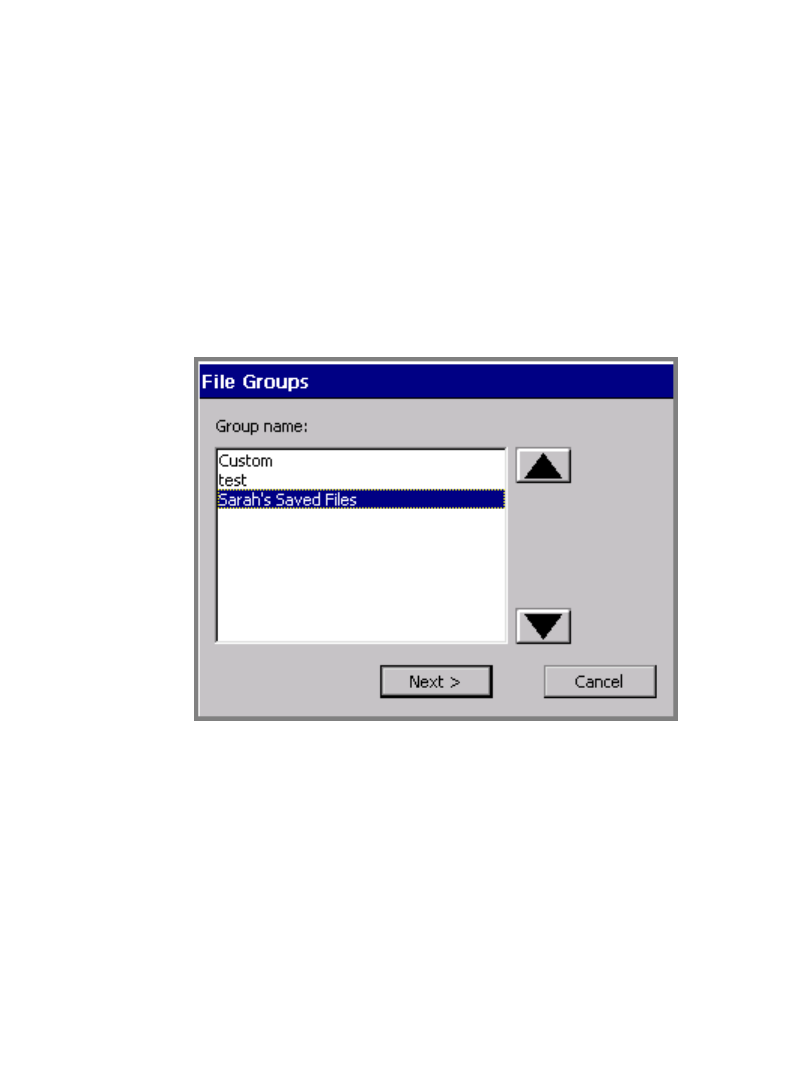
Printing 11-9
4. Choose the Print files in file group option. (Note that the Special Print options
are now grayed out, and the File Group button becomes available.)
5. Choose OK. You’ll see the Print screen (Figure 11-3).
6. Choose OK on the Print screen. You’ll see the Preparing to Print screen
(Figure 11-4), where you can track the printer’s progress while it processes and
prints the labels and pages in the file group.
To print a different file group
You can actually print any file group when you have any label displayed in the
Editor window. It just requires a couple more steps:
1. Follow steps 1-4 in the To print a file group procedure above.
2. Choose the File Group button. You’ll see the File Groups screen:
Figure 11-7. The File Groups screen.
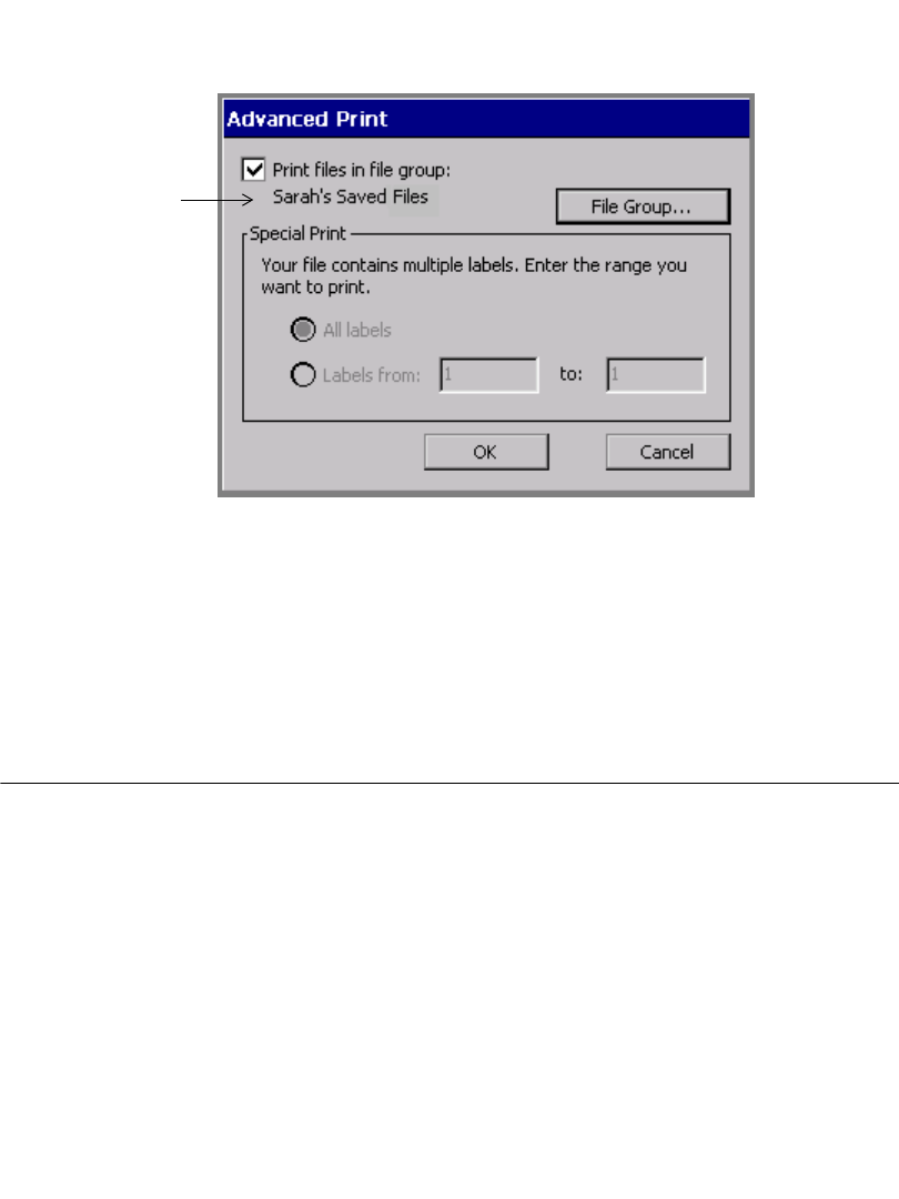
11-10 Checking Supplies
3. Choose the file group that contains the files you want to print, then OK. The
Advanced Print screen displays again, now with the name of the file group you
selected displayed on the screen.
File Group name
you selected
Figure 11-8. The Advanced Print screen for File Group printing.
4. Choose OK. You are returned to the Print screen (Figure 11-3).
5. Choose OK on the Print screen to start the print job. You’ll see the Preparing
to Print screen (Figure 11-4), which tracks the system’s progress as it processes
and prints each file in the file group.
Checking Supplies
When you choose OK to start a print job, the system checks the current label for
size, length, and color against the supplies installed. The information your system
needs is stored in the memory cell flag located on each ribbon and tape cartridge.
The system reads that information every time you print any label.
If the installed supplies are not adequate or appropriate for the print job, in most
cases you’ll see a system message describing the problem, and prompts for the
required supplies. But keep in mind that it’s always a good idea to install the
supplies you want to print with before you compose a label.

Printing 11-11
Checking Size
First, the system checks the size of the printable area of the label in the print job
against the tape you have installed. The printable area is what is left after the
margins are taken into account. Margins vary according to the size of the tape
supply.
Hint! The view of your label on the display screen is a good representation of
how it will print. Correct any size discrepancies before printing to avoid
wasting supplies.
When an object on a label size extends beyond the printable area of the
installed tape, there are two possible results:
zIf the label is one you just created, the system prints the label anyway. Objects
or portions of objects beyond the printable area of the tape can be truncated.
zIf the label is a saved label you have opened to print, the system displays a
message prompting you to change the tape supply.
When the label size is smaller than the printable area of the tape, the system
proceeds to print your label without displaying messages, but how it prints varies
according to how many labels the job contains and the system settings:
zIf the job has just a single label, the system prints the label as is.
zIf the job contains multiple labels, the system checks the Supply saver system
setting.
With Supply saver ON, the system saves tape and ribbon by arranging labels
of the same size together in the print queue. With the Monocolor system and the
Multicolor system, the printer adds dashed lines to show you where to cut the
labels apart. On the Color& Cut system, the printer cuts the labels apart for you.
With Supply saver OFF, the system prints the labels in the normal way: one
per panel, one at a time.
See Supply saver option on page 11-21 for information and examples.
11-12 Checking Length
Checking Length
The system uses the ribbon supply installed in your printer to determine the
maximum printable length for a label. When you start a print job, the system checks
the length of your label page and compares it against the information it records
from your ribbon’s memory cell flag.
Important! The view of your label on the display screen is usually a reliable
representation of how it will print. You should correct any size
discrepancies before printing to avoid wasting supplies.
Minimum length
Two inches (51 mm) is the minimum supply length the system permits for reliable
delivery of a label. If your label is shorter, the system automatically lengthens the
page to meet the required minimum. The content and size of your label on the page
remains the same. You can trim off the excess tape by hand.
Hint! If you turn the Supply Saver option on, you may be able to print multiple
copies of a short label that fill up the two inch minimum page length. For
instance, if you printed two copies of the label shown in Figure 11-1 on
page 11-3, Supply saver would stack them vertically, using up the
minimum page area. See Supply saver option on page 11-21 for
instructions.
Maximum length
The page length the system supports is determined by the installed ribbon. The
maximum supported lengths are:
zFor single-color label printing using continuous color (monochrome) ribbons,
100 inches or 2540 mm.
zFor multi-color label printing using continuous color (monochrome) ribbons, 38
inches or 965 mm.
zFor printing using paneled ribbons (both spot-color paneled ribbons and CYMK
paneled ribbons), the panel length. Panels are 8 inches (203 mm) or 16 inches
(406 mm).

Printing 11-13
Note: Because a reliable value for the maximum supported cut length has not
been determined, the printer will not perform a check prior to printing, to
warn you if the label contains cut objects longer than a specific length.
When you create a label with the supply installed that you intend to print with, if
the label length is longer than the supported print length of the installed ribbon,
you’ll be able to see it on your display screen, as shown in Figure 11-9.
Hint! Keep in mind that other changes besides color can affect the length of the
label. For example, changing the font size or adding an object may
increase the length of the text.
Also keep in mind that in some cases, the printer shows your label as truncated on
the screen (as in Figure 11-9) and when you choose Print, it prints the label
truncated as shown.
In other cases, the printer displays your label at the length you set it or as set by the
template you used to create the label, but when you choose Print, displays a
message and does NOT print the label until you correct the length condition.
For example, if you open a file with a label with a set length, the label is displayed
with the correct length on the screen. If the label is too long to print on the current
supply, you’ll see a message telling you so, and you’ll be returned to the Editor
window. You won’t see the label length truncated on the screen, as shown in
Sample of label too long for installed ribbon. on page 11-14. You then have the
option to:
zInstall a longer panel ribbon
zInstall a continuous color ribbon
zShorten the label length
In this case, you must make one of these changes, or you will not be able to print
this label.
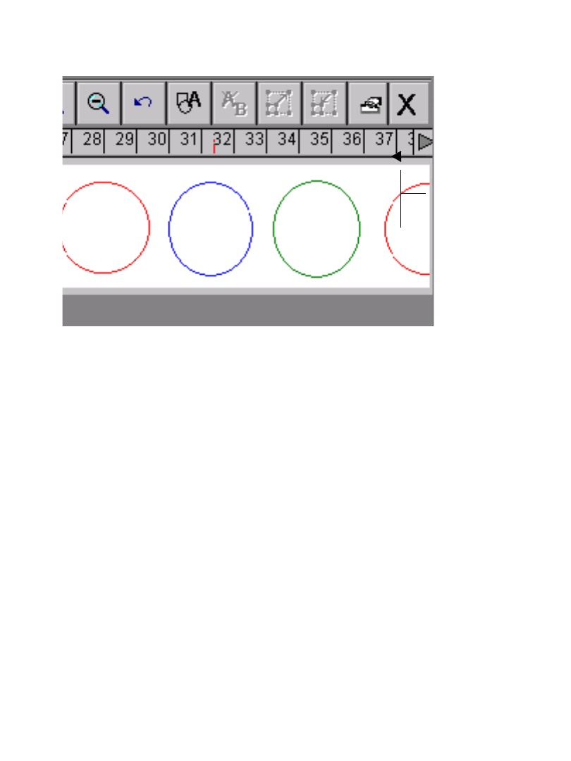
11-14 Checking Length
When the printer truncates labels
Figure 11-9 is an example of a label with an object placed beyond the label length
acceptable to the installed ribbon, where the printer will truncate the label when
you print it:
Figure 11-9. Sample of label too long for installed ribbon.
For the label shown in Figure 11-9, the installed ribbon is a continuous color
monochrome ribbon, and the circles shown are to be printed in various colors, as
labeled. This combination carries a maximum supported length restriction of 38”.
The label shown on the screen is over 38” long. Note that the display indicates the
cutoff point at 38”.
If you attempt to print this label as it is, the printer truncates the job at the
maximum length of 38”, without displaying a warning message. The part of the
circle that extends beyond 38” does not print, just as shown on the display screen.
Non-truncating conditions
You see the actual set label length on your display screen, and the system will not
automatically truncate a label that exceeds the maximum length allowed for the
supplies installed, under these conditions:
zWhen you create a label with continuous color ribbon installed, with single
color objects, unless the objects you added to the label extend beyond the 100”
maximum length for this type print job.
zWhen the length is set for the label, either by you when you create the label, or
by the template you used to create the label.
Maximum
label length
This object
extends
beyond the
length limit,
so will be
truncated as
shown.
RED BLUE GREEN RE
Printing 11-15
zWhen you save your label, then retrieve it again with a panel ribbon installed,
you will see the actual set label length indicated on the screen.
In these cases, when you attempt to print the label, the system displays a Label Too
Long message, and you must correct the label before proceeding.
Cut out label length
The maximum length for cut out labels is 38” or 965 mm. See CHAPTER 10:
Working with Cut-outs, beginning on page 10-1, for more information about cut
out labels.
Checking Color
When you compose a label, the system uses the ribbon supply installed in your
printer to determine which colors you can select. (See CHAPTER 8: Applying
Color, beginning on page 8-1 for more information.)
When you print the label, after completing the length check described in the
preceding section, the system checks your label against what it knows about the
ribbon that is installed. If the job requires that you install different or additional
ribbons, the system prompts you to do so at the appropriate time in the print
process.
Note: For best results, we recommend that you do not plan to swap paneled and
continuous color ribbons within the same print job.
The system also checks the label background color against the installed tape color,
and displays a warning message if there is a discrepancy.
Ribbon and color choices
Depending on your system, you can use several types of ribbon:
Continuous single color ribbon, which is one color throughout the length of
the entire ribbon. All three systems can use this type ribbon.
Paneled ribbon for spot color, which has two, three, or four colors in panels of
8 inches (203 mm) or 16 inches (406 mm) long on each ribbon. The printer
11-16 Checking Color
makes multiple passes over the ribbon to print those colors on the label. Both
the Multicolor and the Color & Cut systems use paneled ribbons.
CYMK ribbon, which has cyan, yellow, magenta, and black panels of 8
inches (203 mm) or 16 inches (406 mm). The printer uses all four color panels
to produce a range of blended colors on your labels. The Multicolor and the
Color & Cut systems can use CYMK ribbons.
Depending on the ribbon installed, you can produce several types of color on your
printed labels:
Single color uses a continuous single color ribbon or one of the colors in a
paneled ribbon. If you apply multiple colors when composing your label:
• With the Monocolor system, the system prints the entire label with the
installed monochrome ribbon.
• With the Multicolor and Color & Cut systems, the system prompts you for
the correct color ribbons.
Note: If all objects on the label are the same color, the system prints with the
installed ribbon, even if the color of the ribbon does not match the color of
the objects.
Spot color uses solid color ribbons, either paneled ribbons or continuous
single color ribbons that you swap in when required. Spot colors print without
blending with other colors to achieve the desired output color.
Blended color uses the cyan, magenta, yellow, and black CYMK ribbons,
either paneled or continuous, that print in combination with each other to
achieve pre-defined blended colors. This is sometimes referred to as full color
printing.
Hint! When a CYMK ribbon is installed, the system assumes that you want to
print in blended color, even if all the objects on your label are the same
color. For more efficient use of supplies, you may want to install a
continuous color ribbon when you are printing a single color.
Printing 11-17
In summary, your system and the installed ribbon together determine what kind of
color you can produce:
Ribbon color needed
When the system needs a different color ribbon installed to complete your print job,
it prompts you with a Color Needed message that asks you to install the required
ribbon, close the printer cover, and click OK to continue the print job. This process
is sometimes called swapping ribbons.
Note: For best printing results, we recommend that you avoid printing entire file
groups that contain labels that require ribbon swapping. When printing file
groups, the printer takes its information from the first label in the group.
The system may not be able to process new ribbon information you add
during the print job in time to affect the appropriate label(s).
Substituting ribbon colors
When printing multiple colors by swapping ribbons, you can substitute a different
color for the color currently being prompted. If you open and close the printer
cover, printing will continue with the current color regardless of whether or not it is
the specific color required by the print job:
System: Produces:
Monocolor model zsingle color
Multicolor model zsingle color
zmultiple spot colors using paneled or continuous
single color ribbons
zblended color, using CYMK ribbons, paneled
ribbons, or continuous single color ribbons
Color & Cut model zsingle color
zmultiple spot colors using paneled or continuous
single color ribbons
zblended color, using CYMK ribbons, paneled
ribbons, or continuous single color ribbons

11-18 Checking Color
A series of dots appears on the Color Needed screen to indicate that the system is
waiting for input, provided you have not installed a new ribbon (by opening and
closing the printer cover), or selected the Continue with Current Ribbon button.
The visual indicator appears on all messages where your input is required to
continue. (See Visual Indicator and Message Box Buttons on page C-2 for
details.)
zIf a spot color paneled ribbon is installed when you select Continue with
Current Ribbon, the next color panel on the ribbon is used to print the
requested color.
zIf a monochrome ribbon is installed when you select Continue with Current
Ribbon, the print job continues with that single color.
zIf you open and close the printer cover, the printer checks the new ribbon color
and resumes printing if the requested color is available. If the requested color is
not available on the new ribbon, the Ribbon Color prompt appears.
Tape color needed
The system response to tape color differs depending on the kind of label you are
printing:
zWhen you are printing a template label and the system needs a different color
tape installed to complete the print job, it prompts you with a Color Needed
message. Install the required tape, close the printer cover, and click OK to
continue the print job.

Printing 11-19
Hint! The system does not re-check the memory cell flag at this point to see if
you installed the correct tape, but continues the print job with whatever
tape is now installed. You may find this useful at times when you want to
override the color choice dictated by the template or indicated on the label.
zWhen you are printing a custom label, the system always assumes you want to
print using the installed tape, and does not check tape color.
zWhen you are printing groups of labels, for best results, make sure all labels in
a group have the same tape supply requirements, including the color
requirement. You should address this issue before print time, when creating the
label group. See About Files and File Groups on page 9-2 for more
information.
Checking for cut out labels
Only 4” (102 mm) wide tapes are appropriate for use with the plotter cutter feature
in the Color & Cut system.
zIf the cut out extends beyond the maximum allowed length or the width of the
tape supply, the printer ignores the cut out area of your label. Your display
screen shows a reliable representation of the cut out on your label, so you
should correct the size problems before proceeding.
zIf the cut out is narrower than the tape supply, the printer proceeds with the job.
Note: Not all 4” (102mm) tape supplies are appropriate for cut outs: for instance,
magnetic tape may not be cut. Check with your supplier for more
information.
Printing Tab Options
The Printing tab provides two additional print options:
zSupply saver, which saves tape and ribbon by arranging labels on pages
zOverprinting, which eliminates the possibility of gaps between colors in some
types of print jobs
11-20 Printing Tab Options
Accessing the Printing tab options
You can set the Supply saver option and the Overprint option from the Main
Menu or, for convenience, from within most applications.
zUse the System Setup screen to set the defaults for your entire system. These
settings you choose on the tab screens apply to every label you compose (with
the exception of Pipe Marker and Right-to-Know labels). See CHAPTER 5:
Setting Preferences, beginning on page 5-1, for more information.
zUse the Application Preferences screen to set the defaults for the system from
within most applications. This saves you having to close an application to go
back to the Main Menu. See Setting Application Preferences on page 6-35
for more information.
Note: You can set Printing options for Pipe Marker and Right-to-Know only
from within those applications.
QuickText does not allow you to set preferences from within the
application.
To set print options from the Main Menu
1. On the Main Menu screen (Figure 3-1 on page 3-2), choose Setup. You’ll see
the System Setup screen, with the Printing tab displayed:
Figure 11-10. The System Setup screen, Printing tab.
2. Set the options as described in the sections that follow.

Printing 11-21
To set print options from within an application
From within the Editor window of any application other than QuickText, press the
<Preferences> key.
Exception: Access the Pipe Marker Preference screen also from the Pipe
Marker Style screen. See Setting Pipe Marker preferences on
page 6-37.
Access the Right-to-Know Preferences screen also from the Right-
to-Know Format screen. See Setting Right-to-Know
preferences on page 6-38.
Supply saver option
Supply saver printing, which is sometimes called multiple up printing, saves tape
and ribbon by arranging labels together in the print queue and printing multiple
labels on the same page.
This option saves tape because it vertically stacks labels that are smaller than the
full width of the tape, so that the full width of the tape is used (see Figure 11-11). It
also saves ribbon because it groups labels to print within a set of ribbon panels.
On the Monocolor and Multicolor systems, the printer adds dashed lines to show
you where to cut the labels apart. On the Color & Cut system, the system cuts out
the individual labels.
Supply saver applies only when:
zYou are printing multiple labels. (They do not have to be multiple copies of the
same label, as long as they meet the size criteria.)
and
zThe labels are smaller than one-half of the printable area (to stack vertically)
or
The labels are shorter than one-half of the length of the panel (to group within a
panel length), when you have paneled ribbon installed.
(See Checking Length on page 11-12 for information about paneled ribbon
restrictions.)
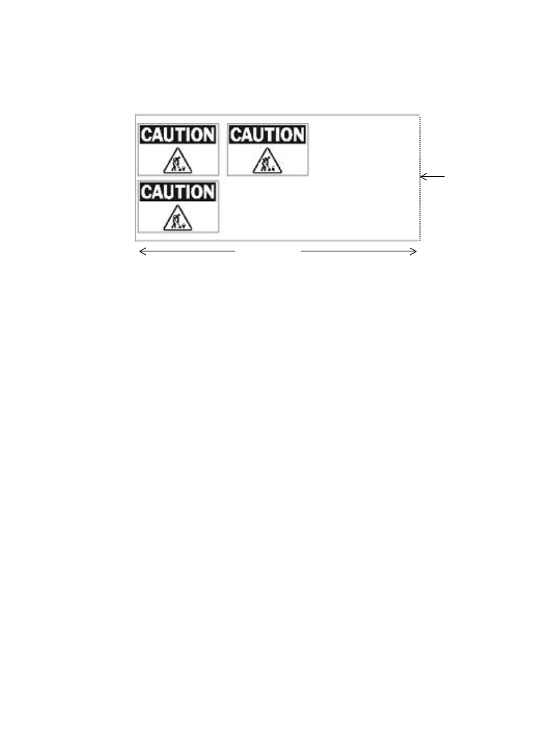
11-22 Printing Tab Options
Figure 11-11 and Figure 11-12 below illustrate how you can save tape with Supply
saver enabled.
Figure 11-11 shows your output with Supply saver enabled and an 8” paneled
ribbon installed. In this job, you want to print three copies of a single label. The
system first checks to see if the labels meet the size criteria. If they do, the system
stacks the labels and prints this output:
Figure 11-11. Sample output with Supply saver ON.
System
shears here
8 inches
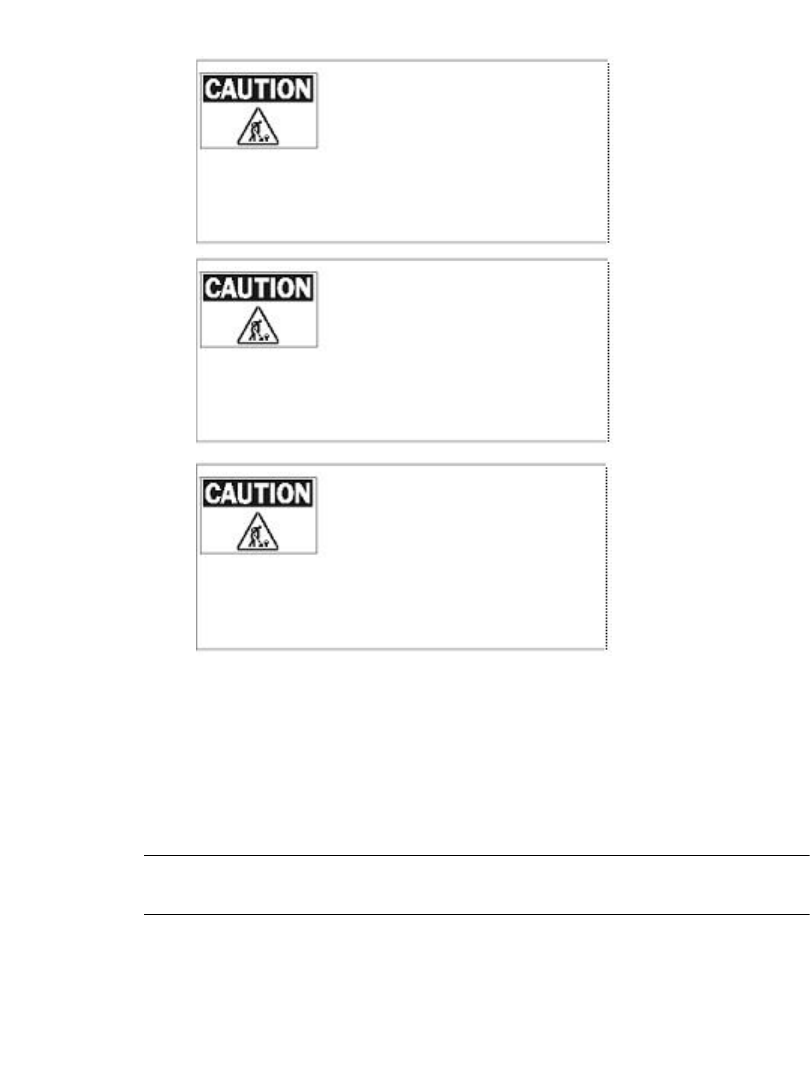
Printing 11-23
Figure 11-12 shows that same print job with the Supply saver option disabled. The
system prints three consecutive 8” long labels:
Figure 11-12. Sample output with Supply saver OFF.
Overprint option
Overprinting eliminates possible gaps between the color areas and the black areas
on your label.
Hint! Try your print jobs with Overprint disabled first. If you are unhappy with
the results, enable the Overprint option.
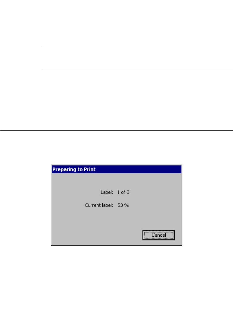
11-24 Canceling a Print Job
zWith Overprint enabled, the system arranges the order in which the colors on
your label print so that black prints last and prints over any previously printed
colors on objects that overlap.
zWith Overprint disabled, areas where black is to be applied are left blank until
black prints. You may see a slight gap between the color areas and the black
areas.
Important! If you are printing using spot color and your label has colored
layers over black background objects, be sure to turn Overprint
OFF. Otherwise, black will obscure the colored layers.
Many users leave Overprint enabled at all times. The main disadvantage to using
Overprint as the default setting is that printing may be slower, because the system
takes the time to analyze the colors in the print job and orders them accordingly.
You may have to swap ribbons more frequently as well.
Canceling a Print Job
When you start a print job, the Preparing to Print screen appears while the
application rasterizes the print job:
Figure 11-13. Preparing to Print dialog box.
Printing may begin while this dialog box is displayed, before rasterization of the
entire job is completed. If you press Cancel, printing will stop immediately and the
printer will eject and cut off anything that has already printed. The Editor window
appears.
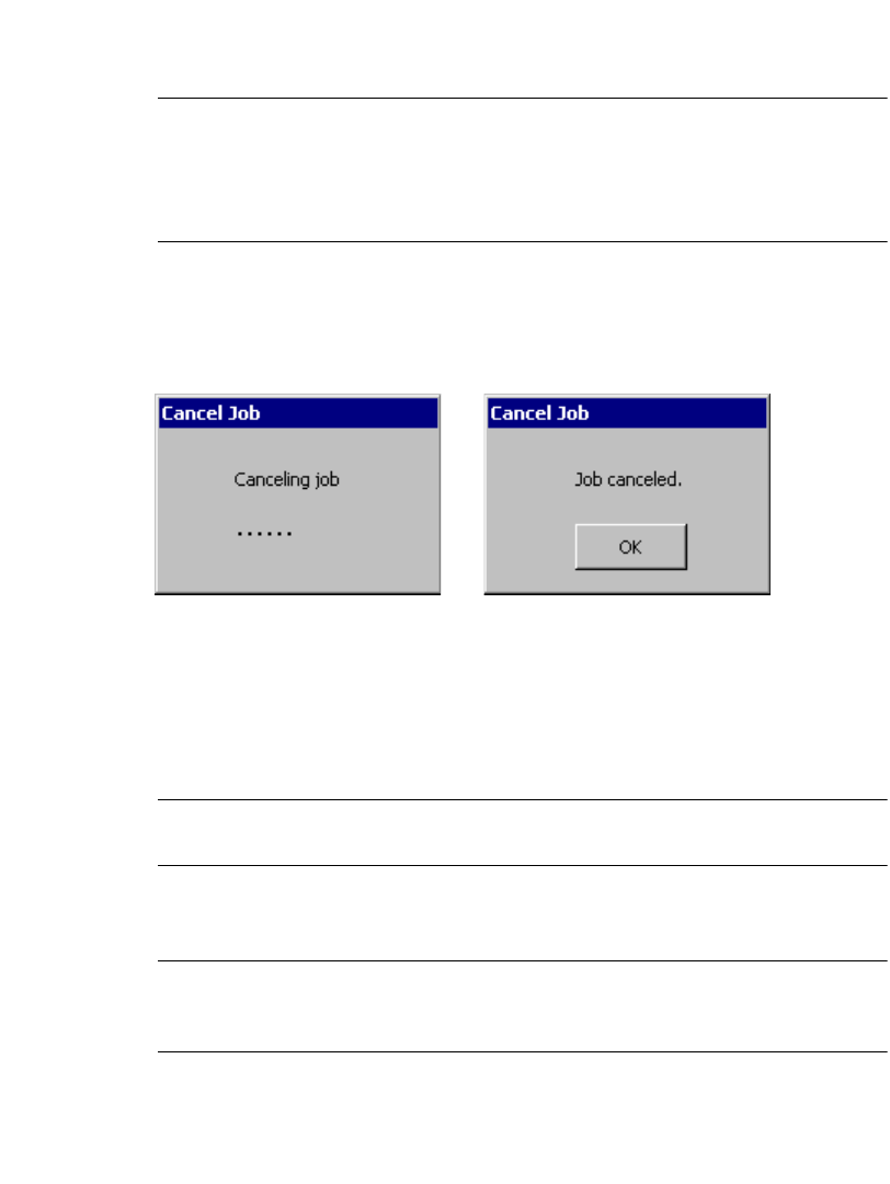
Printing 11-25
The Preparing to Print screen disappears after the job is completely rasterized. To
cancel a print job that continues to print after this dialog box disappears, press
Alt+F1 (Cancel Print).
Note: Pressing Alt+F1 has the same effect as pressing Cancel on the Preparing
to Print screen: printing stops immediately and anything that has printed
is ejected and cut off. For multi-pass print jobs, the entire job is ejected
and cut off, regardless of where the printer is in the print pass when the job
is canceled.
When you press Alt+F1, the Canceling job message immediately appears. Upon
completion, the Job canceled message appears; this message remains until you
press OK:
Figure 11-14. Canceling job and Job canceled messages.
You can press Alt+F1 at any time during printing, regardless of what appears on
the screen (for example, main editor window, template prompt sequence,
application launcher, error message, etc.).
You can also press Alt+F1 to cancel a print job from a PC.
Note: For non-keyboard (peripheral-only) connections, you can press Cancel on
the On Line Status screen to quit printing.
If multiple print jobs are stored, pressing Alt+F1 will cancel all jobs in the printer,
whether they are currently printing or being rasterized.
Note: There is one exception. If you print from a PC and the job has not
downloaded to the printer, it may start to print after the original print job
has been canceled.

11-26 Canceling a Print Job

12-1
This chapter provides instructions and tells you how connecting to a PC can be
useful.
Topics include:
Working with a PC
Setting Up Your System as a Hardware Device
Placing Your System Online
Printing from a PC
Working with the File Management Utility
Upgrading the Operating System
CHAPTER 12 Connecting to a PC
12-2 Working with a PC
Working with a PC
If you have a PC that meets the system requirements, and has the appropriate
software installed, you can connect it to your label printing system. When you
connect your label printing system to a PC:
zYou can use your label printing system as a peripheral printer for the PC. This
means you can use the MarkWare© application running on your PC to make
labels and then print them on your label printer.
zYou can use the File Management Utility to transfer files between your label
printing system and the PC. For example, you can transfer graphic files such as
a logo to your system. The files you transfer can then be used to create output
when your label printing system is not connected to a PC.
Note: If the PC does not support USB, you can use a serial cable to connect your
printing system to a PC. See your PC’s documentation on serial port
connections.
Connecting to a PC 12-3
Setting Up Your System as a Hardware
Device
Before you can use a PC to print to your label printing system or to transfer files,
your label printing system must be set up as a new hardware device.
To set up your label printing system as a hardware device
1. Before turning on the power for either your label printing system or your PC,
connect one end of the USB cable to the printer and the other end to a USB
port on the PC. See Figure 2-2 on page 2-4 for an illustration.
2. Turn on your label printing system.
3. When you see the Main Menu screen, turn on the PC.
4. The operating system on the PC automatically detects your label printing
system. Follow the PC prompts and instructions for setting up your printer as a
new hardware device.
Note: If your PC is not “Plug & Play,” and does not automatically detect the
label printing system, try adding the printer through the PC Control Panel.
On the Control Panel, choose Add/Remove Hardware, and follow the PC
prompts for “Add a New Device.”
5. When the PC procedure prompts you for the location of the device driver files,
insert the CD-ROM labeled GlobalMark 2 Product CD in the CD-ROM drive of
the PC, and enter the address for the CD-ROM drive when prompted.
6. Follow the prompts on your PC. The PC reads and installs the correct drivers.
Note: You may need to restart both systems after installation is complete.
Your PC is now set up to communicate with your label printing system.
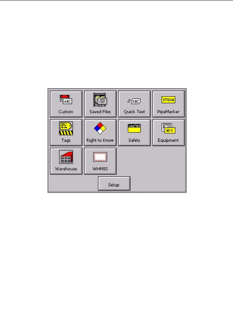
12-4 Placing Your System Online
Placing Your System Online
Before you place your printing system online, you must reset some system settings.
Setting Online Options
Use the System Setup screen online tab options to:
zSet up the type of connection you want to use: USB or serial.
To set Online options
1. On the Main Menu screen, choose Setup:
Figure 12-1. The Main Menu screen.
You’ll see the System Setup screen (Figure 5-1 on page 5-2).
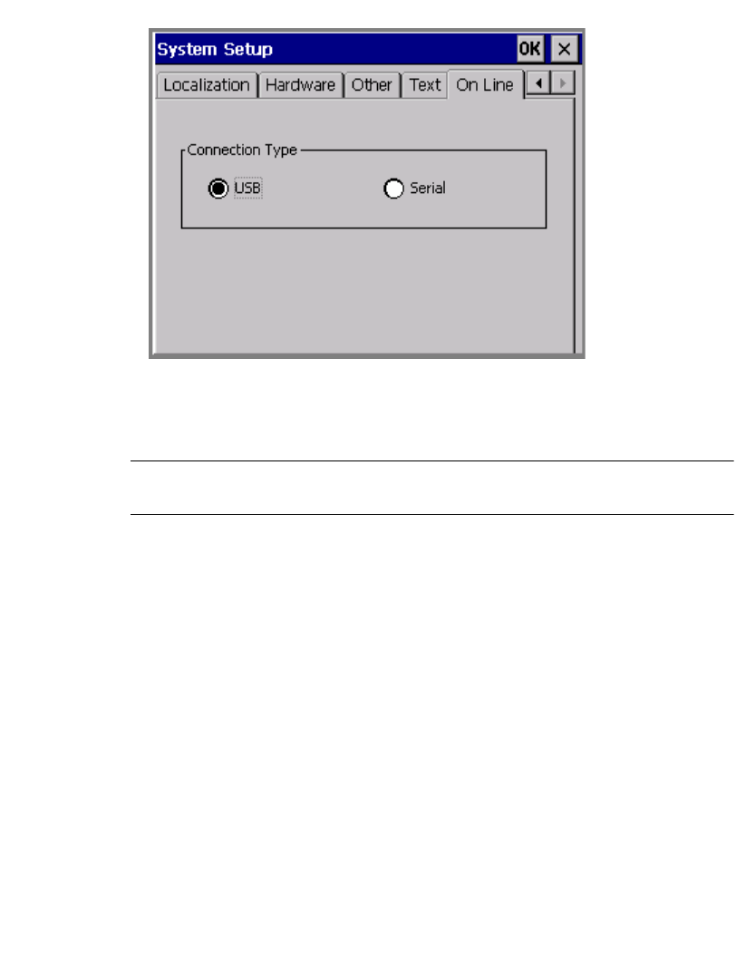
Connecting to a PC 12-5
2. Choose the online tab, shown here:
Figure 12-2. The online tab screen.
3. Choose a connection type. If your PC does not have a USB connector, choose
serial.
Note: You’ll also use the File Management Utility to upgrade the operating
system for your printer.
4. Choose OK. You’ll be returned to the Main Menu screen.
Connecting your system and a PC
In this procedure, you make the actual connection between the PC and your printer.
To place your label printing system online
1. Connect one end of the cable to your printing system and the other to a PC.
The cable you use, USB or serial, should be same as you used in the procedure
described in Setting Up Your System as a Hardware Device on page 12-3.
2. Turn on your printing system.
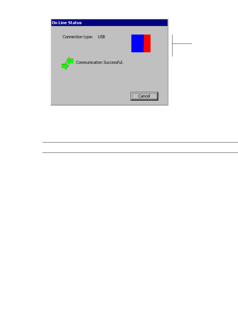
12-6 Placing Your System Online
You’ll see the Online Status screen, which displays the connection type and a
progress box that indicates you are receiving print data from the PC:
Image
refreshes to
indicate
transmission
of print data
from PC
Figure 12-3. The Online Status screen.
You can now print to your label printing system from MarkWare or transfer files
using the File Management Utility.
Note: You can press Cancel to stop the data transfer and cancel the print job.

Connecting to a PC 12-7
Printing from a PC
Before you can use your label printing system as a peripheral printer, you must
perform these tasks:
1. Set up your label printing system as a hardware device. Follow the instructions
in Setting Up Your System as a Hardware Device on page 12-3.
2. Install the MarkWare© application. Follow the installation instructions found in
the MarkWare User’s Guide.
3. Install the appropriate printer driver for your printer. Follow the instructions
included with the driver.
Hint! Connect your label printing system to the PC and place it online before
running the MarkWare and driver installation on the PC. The print driver
install function includes a utility that will help you if you are using a serial
port for your printer.

12-8 Working with the File Management Utility
Working with the File Management Utility
The File Management Utility is an application included with the GlobalMark 2
printer. Use the File Management Utility to do the following:
• Transfer files from the PC to GlobalMark 2
• Transfer files from the GlobalMark 2 to a PC
• Manage existing GlobalMark 2 printer files
• Upgrade existing GlobalMark 2 printer files using an external FTP site or CD-
ROM.
Note: File Management Utility can only be used with serial (COM) on Windows
NT4.0
Storage locations for exported files
The MarkWare application contains a \Download folder in the main \MarkWare
directory. In a standard system, this would be located at C:\Program
Files\Brady\MarkWare\Download.
Document and Template files
The MarkWare application’s export feature prepares document and template files
for use on your label printing system. See the MarkWare© User’s Guide for more
information.
Table 12-1 shows file locations for both your PC and your printing system, and
assumes you are using the \Download directory on the PC to organize the files you
want to transfer to your label printing system.
Important! Your label printing system recognizes only files with the file
extensions shown in Source File Types on page 12-9.
Connecting to a PC 12-9
TABLE 12-1. Source File Types
Hint! You can download Right-to-Know and Pipe Marker documents.
However, you must open these files through the Custom application on
the standalone machine.
File Type Extension Transfer to (Printing System) Transfer from (PC
Location)
Graphic Files *.bmp, *.wmf \Graphics\Category name (It is
recommended that you create a My
Graphics folder in Graphics;
however, you can save the graphic in
any existing category folder)
Retrieve files from storage
locations on your PC
Cut Out Graphics *.cog \Cut Graphics\Category name (It is
recommended that you create a My
Cut Graphics folder in Cut
Graphics; however, you can save the
cut graphic in any existing category
folder.)
Retrieve files from storage
locations on your PC
Document Files *.lbl, *.mw \Saved files\Category name (It is
recommended that you create a My
Documents folder in Saved Files;
however, you can save the document
in any existing category folder.)
Retrieve files from storage
locations on your PC
Template Files *.tpl \Applications\My
Templates\Templates\Default
category name
Retrieve files from storage
locations on your PC
Fonts *.ttf \Fonts Retrieve files from storage
locations on your PC
Cut Out Fonts *.tvf \Cut Fonts Retrieve files from storage
locations on your PC
Text Lists *.txt \Saved Lists Retrieve files from storage
locations on your PC
Other *.* These files may not be compatible
with the printer and will not be
converted to the proper format.
Retrieve files from storage
locations on your PC
12-10Working with the File Management Utility
Note: In order to create a cut out graphic (*.cog), you must open the graphic in a
graphic editor and save it as an *.ai file. Then, rename the file with the
*.cog extension in Explorer.
Installing the File Management Utility
To install the File Management Utility, complete the following steps:
1. Insert the GlobalMark 2 Utilities CD-ROM.
2. Select Install File Management Utility.
OR If Autorun is disabled, you can begin the installation process manually:
1. Insert the GlobalMark 2 Utilities CD-ROM.
2. Click on Start|Run
3. Type D:\File Management Utility\Setup.exe and click OK.
Note: Follow the InstallShield Wizard’s setup instructions until you have
finished the installation. (If an error occurs, please verify that you meet or
exceed the recommended system requirements.)

Connecting to a PC 12-11
Launching the File Management Utility
Once the File Management Utility is installed on your PC, you can launch it by
selecting the File Management Utility shortcut or icon (it will then attempt to
connect with your computer).
Communication Status
The File Management Utility’s Main Menu’s screen shows the communication
status between the PC and printer:
Communication Successful
If the Communication Successful message displays, you will be able to work with
the File Management Utility.
Communication Failed
If the Communication Failed message displays, you will need to manually establish
communication by completing the following steps:
1. Check the Port setting to be sure it matches the Printer to which it is connected.
2. Click the Configure Port button to verify the selected Port’s settings. This
button directs you to the Port Configuration Tab in the Windows operating
system.
3. Click the Test Connection button after all communication selections are
verified, making sure the printer is attached to establish communication.
Note: You may have to repeat this process if the Port or Configure Port
selections are incorrect.
12-12Working with the File Management Utility
File Management Utility Main Menu
Figure 12-4. File Management Utility main screen
The File Management Utility main screen displays the following functions:
zTransfer Files to Printer lets you transfer files on your computer’s hard drive
to your printer’s internal memory or to its external storage card.
zTransfer Files from Printer lets you transfer files from either your printer’s
internal memory or from its external storage card to your computer’s hard drive.
zManage Printer Files lets you manage files on your printer’s internal memory
and on the external storage card inserted into your printer.
zUpgrade Printer Files lets you upgrade files in your printer’s internal memory
online, using an automated process.
Transferring and Managing Files
To transfer and manage files between the PC and the printer, complete the
following steps:
1. Select one of the following options:
Connecting to a PC 12-13
•Transfer Files to Printer
• Transfer Files from Printer
• Manage Printer Files
2. Select the Source File Type from the drop-down box.
3. Select the Source to copy, move or delete files.
Important! Your label printing system recognizes only files with the file
extensions shown in Source File Types on page 12-9.
4. Select the Destination folder from one of the following locations:
• GlobalMark 2\Internal\(printer’s internal memory) file directory structure
• GlobalMark 2\External\(printer’s external storage card) file directory
structure
Note: The File Management Utility may create folders for you. For example,
if file type Graphics is selected, Graphics\My Graphics will be
created for you. Click New Category to create a new category or
folder on the Destination drive by entering its name in the field on the
dialog box.
5. Select the File(s) from the Source or Destination by holding down the Shift or
Ctrl key while clicking on each file name with the mouse to select multiple
files.
Note: Only files of the selected File Type will appear. To return to the original
folder, use the Source or Destination drop-down menus.
6. Select one of the following buttons:
a. Copy: to copy the files from one destination to another.
b. Move: to move files from one destination to another.
c. Delete: to delete files from the Source. The Verify Delete window will
display, listing the files you are about to delete. Click Ye s to continue
or No to cancel.
Note: Click the Refresh button to refresh the contents of the File Directory
Structure as needed.
12-14Working with the File Management Utility
TABLE 12-2. Error Messages
7. Select Back to Main Screen to return to the Main menu or Exit to exit from the
utility.
Insufficient Space window Displays if there is not enough
memory within the destination to
transfer the selected files.
Loss of communication window Displays if communication between
the attached printer and PC is lost.
You will need to exit the utility and
follow the steps for connecting again.
Verify Valid Destination window Displays if the entered file
destination is incorrect. You will
need to enter another destination for
the files that you have selected.
Operation failed Displays if the process failed.

Connecting to a PC 12-15
Upgrading the Operating System
Note: The Upgrade Printer Files button will be available but not functional
until there is a new product release. You will see the message No updates
at this time.
When new operating systems for your label printing system are available, if you
have access to a PC, it’s simple to upgrade.
Note: If you do not have access to a PC, instructions for upgrading will be
shipped to you with your upgrade card.
To upgrade using the File Management Utility (online)
1. Place your system online for transferring files. See Placing Your System Online
on page 12-4 for instructions.
2. After establishing a guest connection between your label printing system and
the PC, start the File Management Utility program on the PC.
3. Select Upgrade Printer files.
4. Establish an Internet connection.
5. Select Upgrade from Internet.
6. After the upgrade is done, you will need to restart your label printing system.
To upgrade using a CD-ROM
1. Place your system online for transferring files. See Placing Your System Online
on page 12-4 for instructions.
2. After establishing a guest connection between your label printing system and
the PC, start the Upgrade Utility program on the PC.
3. After the upgrade is done, you will need to restart your label printing system.

12-16Upgrading the Operating System

A-1
The tables that follow provide the symbol, the unicode value, and the decimal value
for special characters you can use with your label printing system.
Table 1 on page A-2 lists special characters you can insert when using these fonts:
zArial 65 for BRC
zArial for BRC
zTimes New Roman for BRC
Table 2 on page A-6 lists special characters you can insert when using:
zBrush Script for BRC
See Adding special characters to text on page 7-8 for information about inserting
symbols and other special characters on your labels.
Appendix A Special Characters
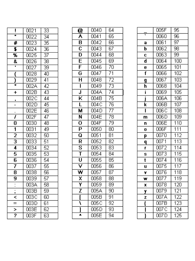
A-2 Special Characters
TABLE 1. Special Characters for Arial 65 for BRC, Arial for BRC, and Times New Roman
for BRC fonts, listing symbol, unicode value, and decimal value for each.T
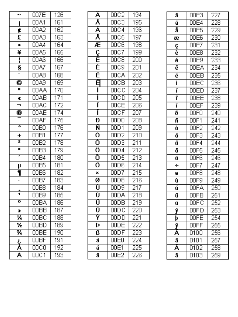
Special Characters A-3
TABLE 1, CONTINUED
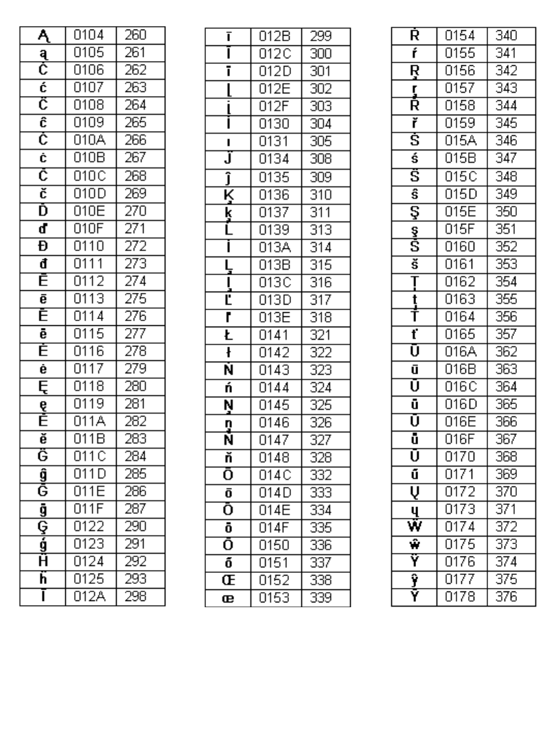
A-4 Special Characters
TABLE 1, CONTINUED
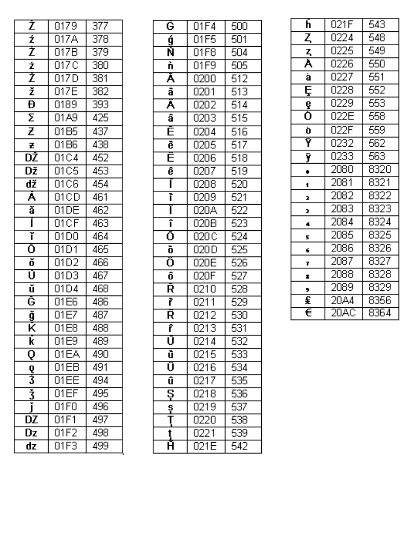
Special Characters A-5
TABLE 1, CONTINUED
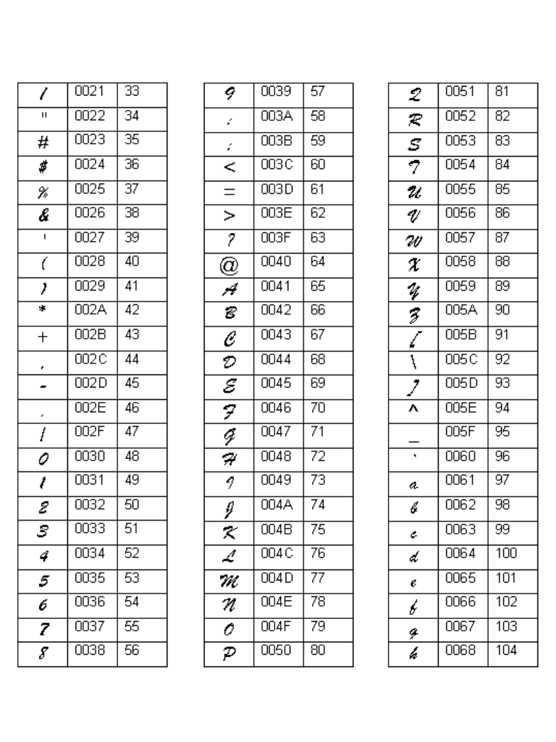
A-6 Special Characters
TABLE 2. Special Characters for Brush Script for BRC font, listing the symbol, unicode
value, and decimal value for each
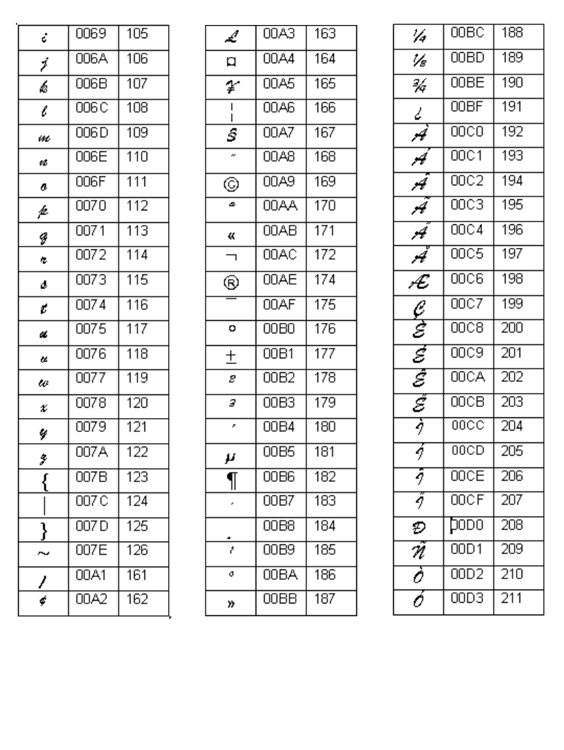
Special Characters A-7
TABLE 2, CONTINUED
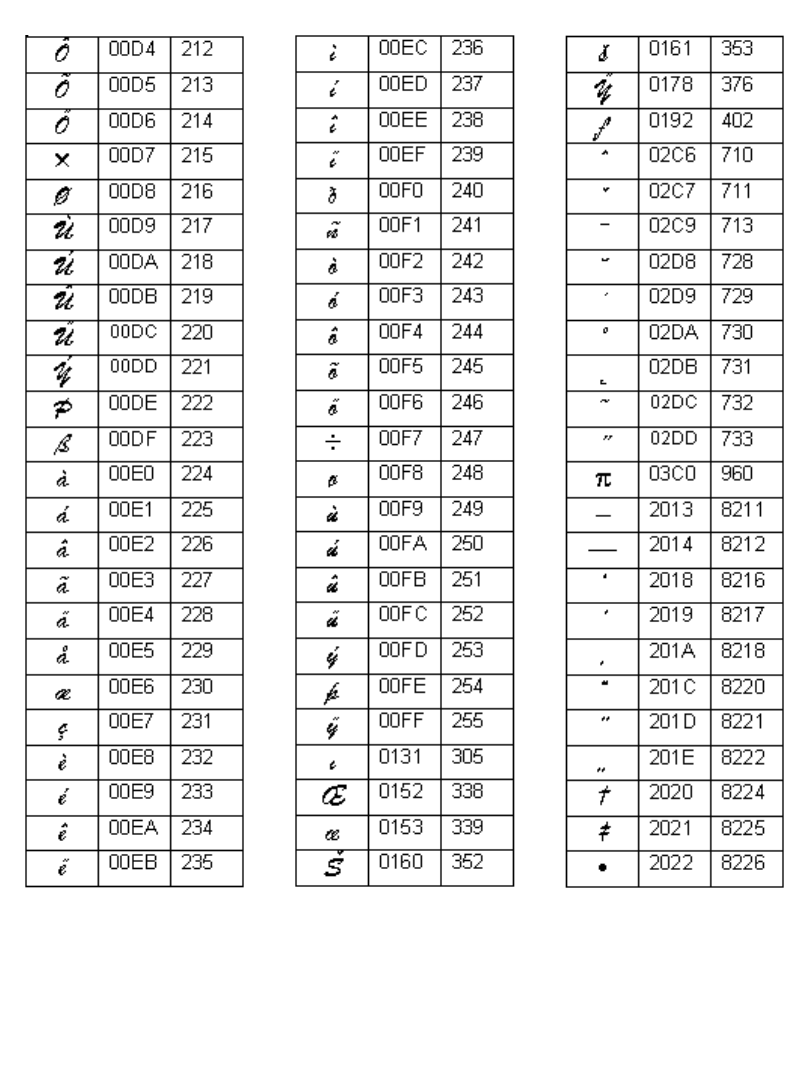
A-8 Special Characters
TABLE 2, CONTINUED
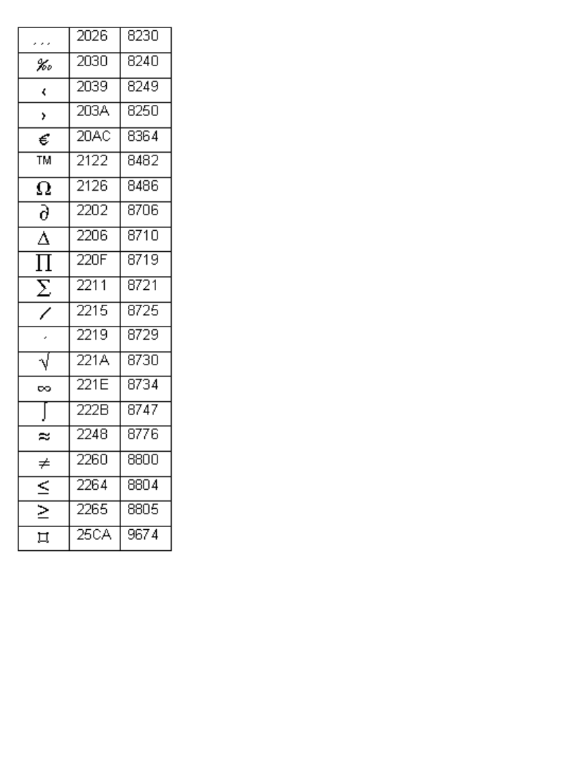
Special Characters A-9
TABLE 2, CONTINUED

A-10Special Characters

B--1
If you have the Color & Cut system, you may need this information.
The instructions in this appendix tell you:
zHow to remove and replace your printer’s cutting blade.
zHow to adjust the depth of the cuts on your labels.
zHow to clean the cutting blade.
Appendix B Cutter Maintenance

B-2 About the Cutting Mechanism
About the Cutting Mechanism
Your plotter cutter consists of a stylus blade in a holder, mounted on a track in your
printer. The stylus is moved mechanically across the tape in the design you
designate.
The stylus consists of the cutting blade and the apparatus that holds the blade in
place. It is contained in a holder that fits into the tracking mechanism in your
printer. Figure B-2 on page B-4 provides a close-up view of the stylus holder.
To produce a cut out, the printer moves the stylus using the tracking mechanism
across the tape, cutting the tape in the design you specified. The printer delivers the
cut out label with the backing in place. All you have to do is strip the cut out from
the backing.
You may need to adjust the depth of the blade within the stylus from time to time,
and you may need to replace or clean the stylus holder as well. The sections that
follow describe these procedures.
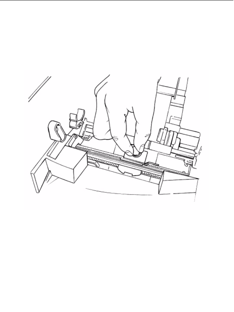
Cutter Maintenance B-3
Removing the Stylus Holder
Follow these instructions to remove the stylus for adjusting, cleaning, or replacing.
Step 1: Turn the power off, then open the printer.
Step 2: Move the stylus holder mechanism to the center of the track, to make it easier to
work with.
Step 3: To disengage the stylus holder, turn it counterclockwise to unscrew it, as shown in
Figure B-1.
Figure B-1. Removing the stylus holder.
Step 4: Pull straight up to remove the stylus holder from the tracking mechanism.
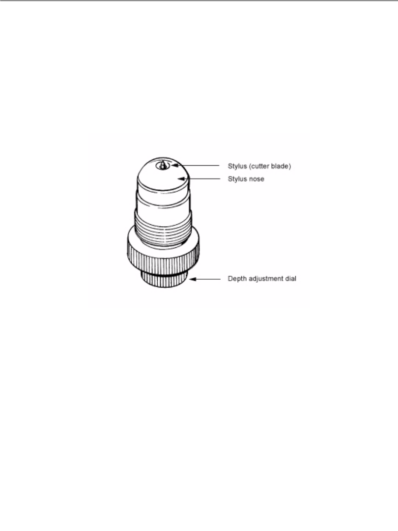
B-4 Adjusting the Cut Depth
Adjusting the Cut Depth
You may need to adjust the stylus blade on your cutter when:
zThe cuts on your cut out labels are either too deep or too shallow.
zYou install tape supplies of varying thickness.
The stylus holder has an adjustment dial you use to change the depth at which the
stylus blade cuts the tape.
Step 1: Turn the power off, and open the printer. Follow the instructions in the Removing
the Stylus Holder section above to remove the stylus holder, shown here:
Figure B-2. The stylus holder.
The stylus blade protrudes very slightly from the stylus nose. The stylus glides
across the tape when cutting your label.
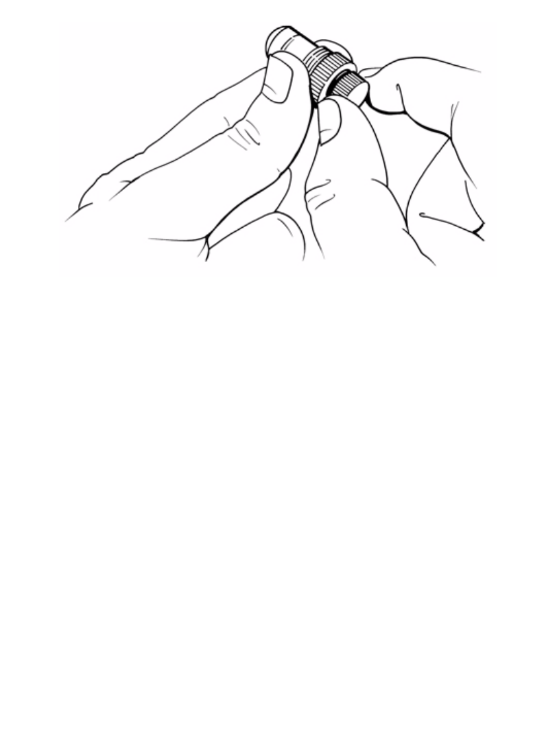
Cutter Maintenance B-5
Step 2: Hold the stylus holder as shown here (Figure B-3) to make the adjustment.
Figure B-3. Adjusting the Stylus Depth change the diagram.
Step 3: Start by turning the adjustment dial slowly.
zTurn the dial clockwise to increase the cutting depth.
zTurn the dial counter-clockwise to decrease the cutting depth.
Step 4: Test the stylus before re-installing it:
1. Take a sample piece of the installed tape, and place it flat on a hard surface
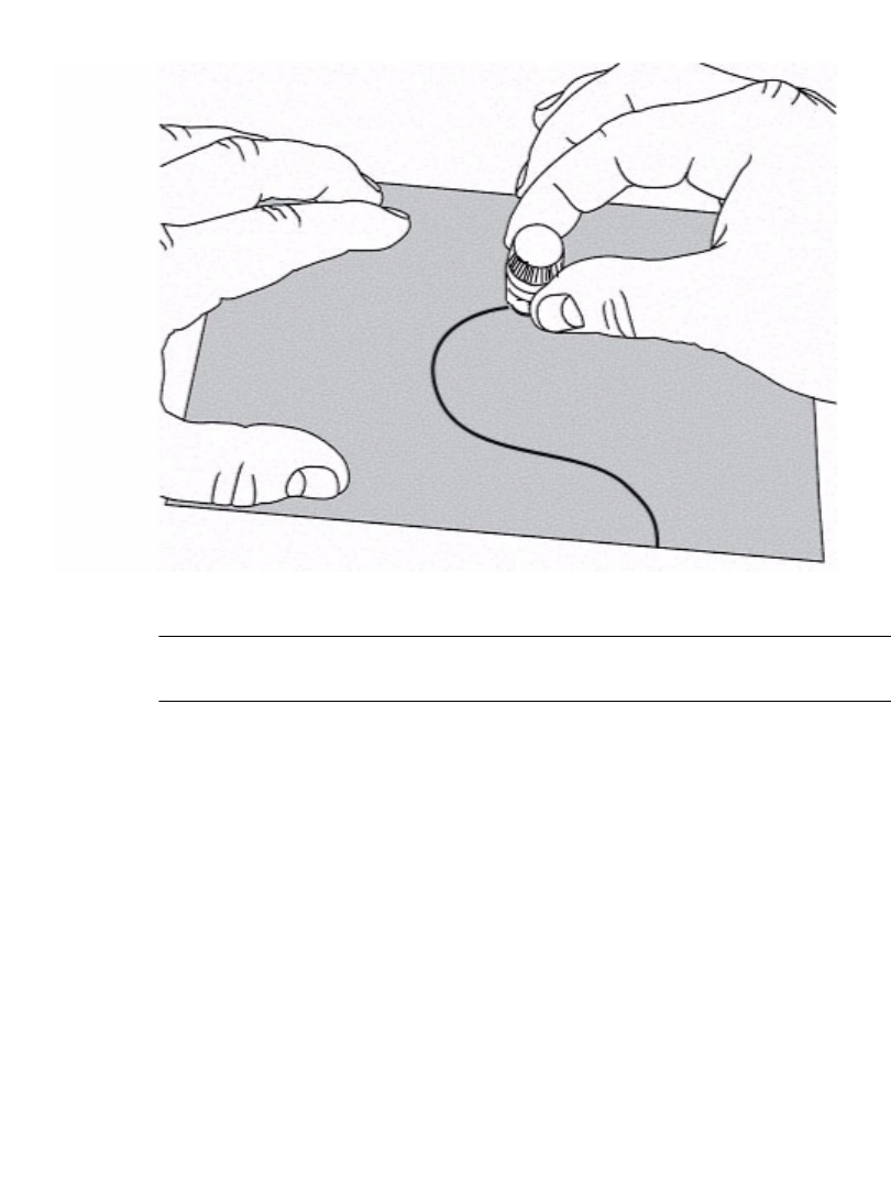
B-6 Adjusting the Cut Depth
2. Holding the stylus holder perpendicular to the surface, glide the stylus nose
lightly cross the tape. need diagram with new stylus holder
Figure B-4. Testing cutting depth.
Note: Apply slight pressure. Make sure the stylus holder is positioned straight
vertically.
3. Check the tape to see if the cut is correct. The cut should go through the tape,
but leave the backing paper unscored.
Step 5: Make any adjustments required to the stylus depth, then test again.
Step 6: Reinstall the stylus holder. Seat it in the mechanism, then turn it clockwise until it
stops.
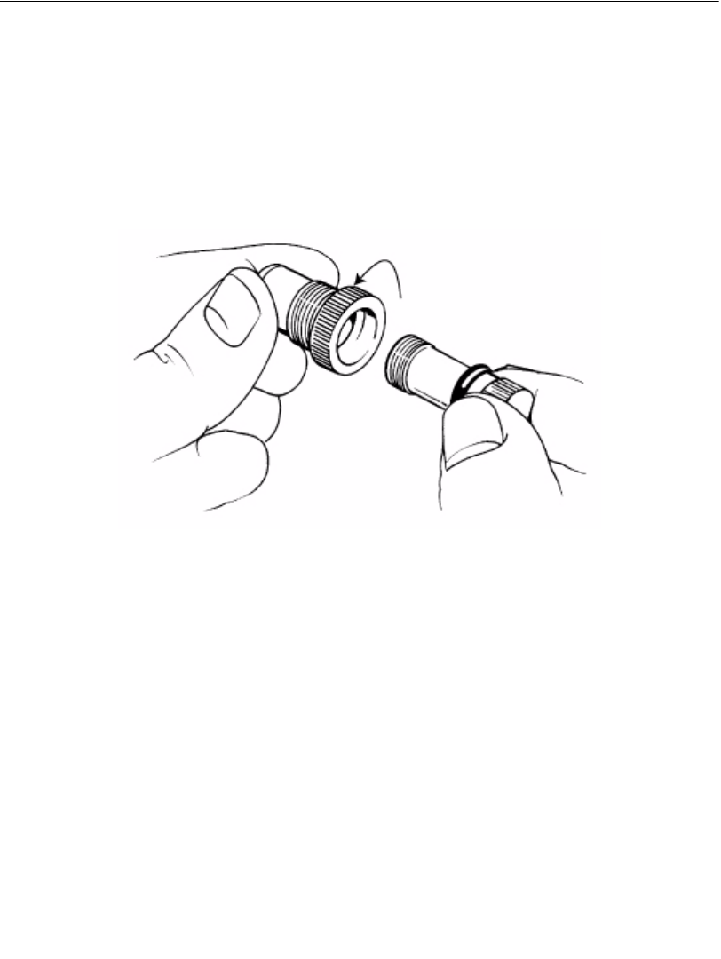
Cutter Maintenance B-7
Replacing the Stylus Blade
At some point, especially after prolonged use with specialty tapes, you may have to
replace the stylus blade.
Step 1: Turn the power off, and open the printer. Follow the instructions in Removing the
Stylus Holder on page B-3.
Step 2: Holding the stylus holder in both hands as shown below, keep the nose end of the
mechanism stable and turn the other end counterclockwise, loosening it until the
two parts separate. new diagram
Figure B-5. Detaching the stylus.
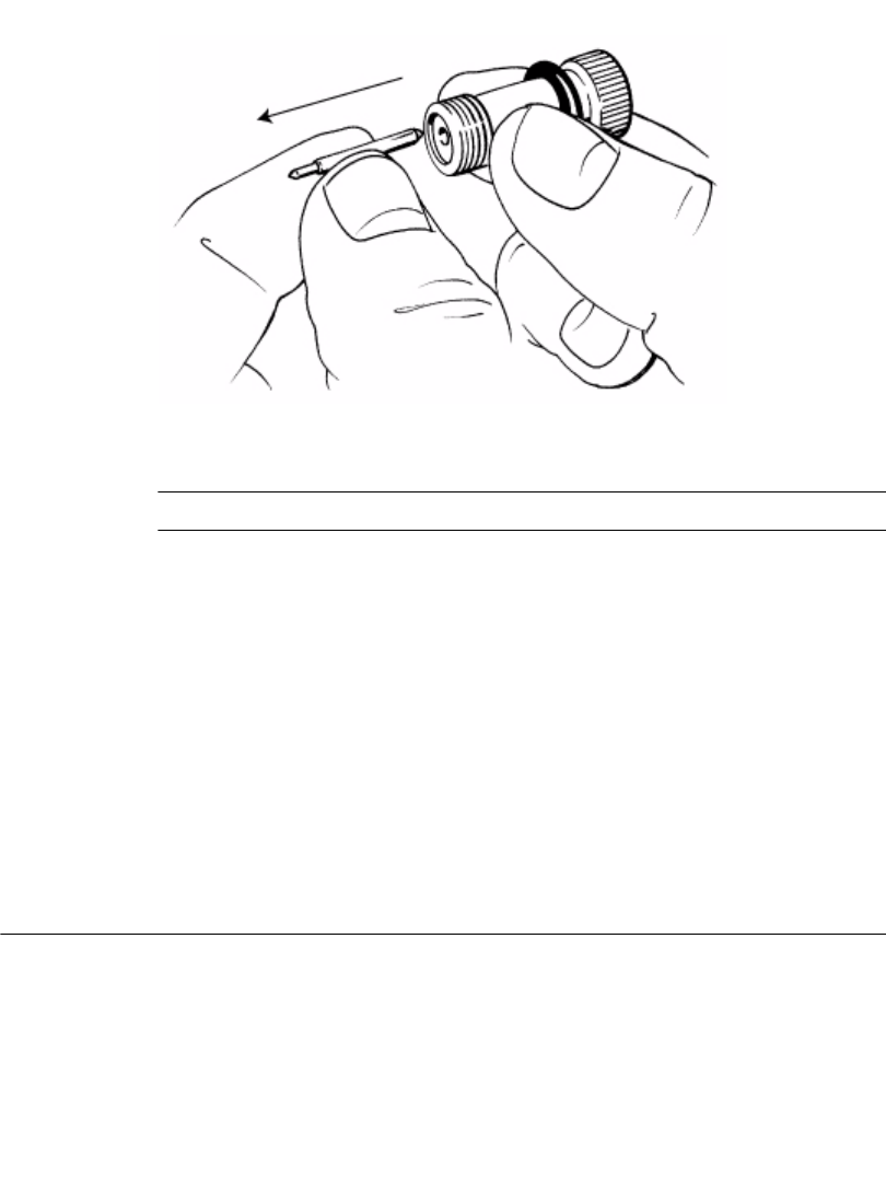
B-8 Cleaning the Stylus
Step 3: Carefully pull on the blade to remove it, as shown here: new diagram
Figure B-6. Removing the blade.
CAUTION:Be careful to grasp the blade on the shank, and not on the cutting edge.
Step 4: Insert the new blade.
Step 5: Reconnect the two parts of the stylus holder:
Push the blade holder as far down as possible, then turn it clockwise, until you feel
the threads engage. Turn until the stylus protrudes from the opening, as shown in
Figure B-2 on page B-4.
Step 6: Adjust the blade depth. Follow the instructions in Adjusting the Cut Depth on
page B-4.
Step 7: Reinstall the stylus holder. Seat it in the mechanism, then turn it counter-clockwise
until it is securely seated.
Cleaning the Stylus
Clean the stylus with Isopropyl alcohol and a cotton-tip swab. These are the same
materials you use to clean the print head on your printer, described in Cleaning
your system on page 2-13. (You may already have purchased a cleaning kit with
your printer.)
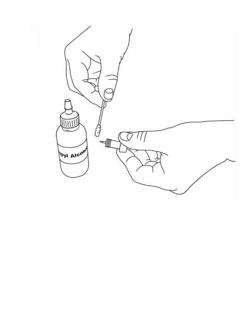
Cutter Maintenance B-9
Step 1: Turn the power off, and open the printer. Remove the stylus as described in Steps 1
and 2 in Removing the Stylus Holder on page B-3.
Step 2: Apply alcohol to the cotton swab, and wipe the stylus blade as shown here:
Figure B-7. Cleaning the stylus blade.
Step 3: Reconnect the two parts of the stylus holder:
Push the blade holder as far down as possible, then turn it clockwise, until you feel
the threads engage. Turn until the stylus protrudes from the opening, as shown in
Figure B-2 on page B-4
Step 4: Adjust the blade depth. Follow the instructions in Adjusting the Cut Depth on
page B-4.
Step 5: Reinstall the stylus holder. Seat it in the mechanism, then turn it clockwise until it’s
securely seated.

B-10Cleaning the Stylus

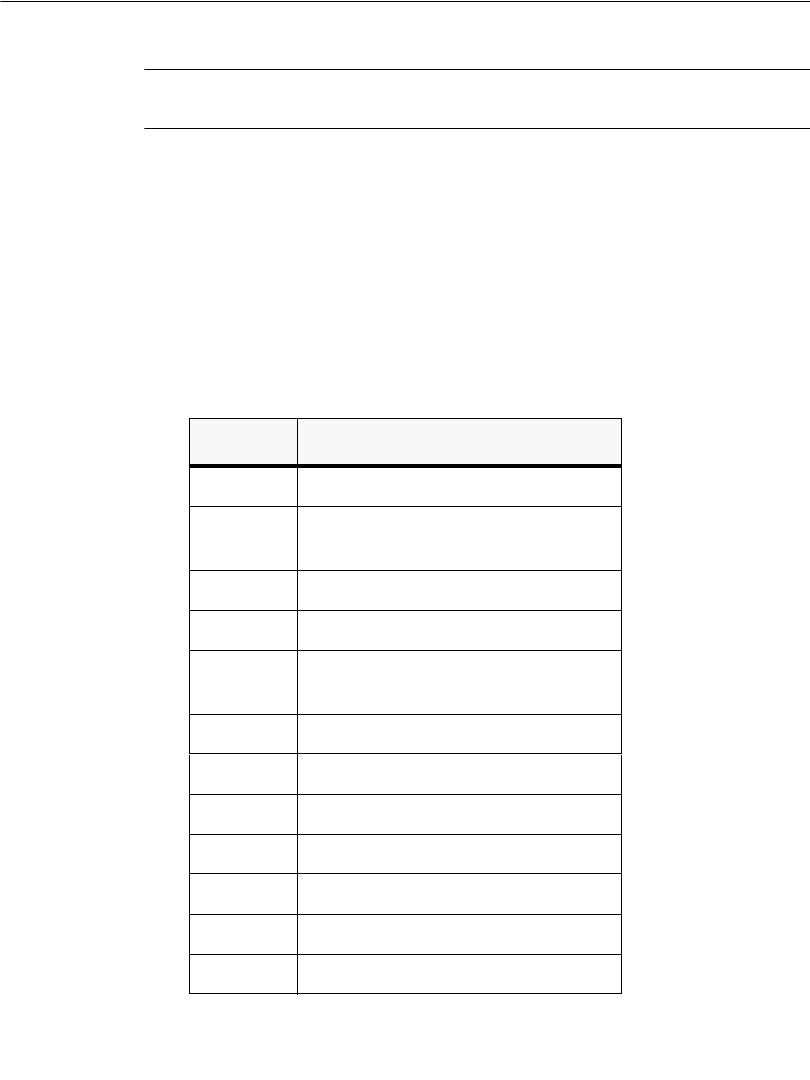
C-2 Error Messages
Error Messages
Note: When an error message appears, it remains on the screen until you correct
the error condition.
The table below shows the error code reported by the system firmware, the
condition that generated that error code, the error message, the user action required
to clear the error message, and any additional information.
When a print job is canceled because of an error condition, the printer attempts to
eject and cut off the unfinished print job (where doing so will not harm the printer).
In instances where that is not possible, the error message provides additional
instructions for removing the partial output and returning the printer to a usable
condition.
TABLE 1. Error Messages
Code User Action
15 Close printer cover.
16 Close printer cover, and advance and
shear tape.
17 Close printer cover.
18 None
19 Remove partial output, reload tape,
then advance and shear.
48 Install tape with valid memory cell.
49 Install tape.
50 Install tape with valid memory cell.
51 Install tape with valid memory cell.
52 Install tape with valid memory cell.
53 Reinstall tape or install new tape.
54 Clear tape jam.
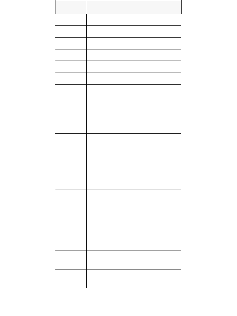
Error Messages C-3
55 Reload tape correctly.
56 Clean sensor and reload tape.
57 Replace ribbon.
58 Replace ribbon.
59 Replace ribbon.
60
61 Remove ribbon.
62 Install wider ribbon.
63 Install ribbon and close cover or,
press Continue with Current Ribbon
button.
64 Install ribbon with valid memory
cell.
65 Install ribbon with valid memory
cell.
66 Install ribbon with valid memory
cell.
67 Install ribbon with valid memory
cell.
68 Install ribbon with valid memory
cell.
80 Clear jam in shear cutter path.
81 Clear jam in tape path.
82 None.
Service required
83 None.
Service required
Code User Action
C-4 Error Messages
84 Replace ribbon.
85 Clean sensor (part of tape guides).
87 Clear tape jam.
88 Clear tape jam.
89 None.
Service required
90 None
91 None
92 None
93 None
Code User Action
