Brady BDC2000 BDC2000 RFID Assembly User Manual Revised
Brady Corporation BDC2000 RFID Assembly Users Manual Revised
Brady >
Users Manual Revised
_______________________________________________________________________________
Brady BDC2000 RFID Assembly
BDC2000 RFID PCB ANT2000 Antenna PCB
MANUFACTURER HEADQUARTERS:
Brady Worldwide, Inc.
6555 W Good Hope Road
Milwaukee, WI 53223 USA

_______________________________________________________________________________
Table of Content
_Toc453241779
1. Introduction ................................................................................................................. 8
1.1 Description........................................................................................................... 8
1.2 Specification ........................................................................................................ 9
2. Installation ................................................................................................................. 10
2.1 Connections ....................................................................................................... 11
3. Operation ................................................................................................................... 12
List of Figures
Figure 1. Block Diagram of Brady BDC2000 RFID Assembly and Connection to Host ... 8
Figure 2. photo of the Brady BDC2000 RFID Assembly ................................................. 10
List of Tables
Table 1. Specification of Brady BDC2000 RFID Assembly.............................................. 9
Table 2. JST B6B-PH-K-S ................................................................................................ 11
Table 3. JST B2B-PH-K-S ................................................................................................ 11
Table 4. Samtec 10-Position Dual Row ............................................................................. 11
Table 5. BDC SPI Configuration ....................................................................................... 12

_______________________________________________________________________________
Copyright
This manual is copyrighted with all rights reserved. No portion of this manual may
be copied or reproduced by any means without the prior written consent of BRADY
Worldwide, Inc.
While every precaution has been taken in the preparation of this document, BRADY
assumes no liability to any party for any loss or damage caused by errors or
omissions or by statements resulting from negligence, accident, or any other cause.
BRADY further assumes no liability arising out of the application or use of any
product or system described, herein; nor any liability for incidental or consequential
damages arising from the use of this document. BRADY disclaims all warranties or
merchantability of fitness for a particular purpose.
Trademarks
Brady BDC2000 RFID Assembly is a trademark of BRADY Worldwide, Inc.
Microsoft and Windows are registered trademark of Microsoft Corporation.
BRADY reserves the right to make changes without further notice to any product
or system described herein to improve reliability, function, or design.
© 2016 BRADY Worldwide, Inc. All Rights Reserved
Brady Worldwide Inc.
6555 West Good Hope Road
Milwaukee, WI 53223 U.S.A.
Telephone: 414-358-6600 USA Domestic
Facsimile: 414-438-6958

_______________________________________________________________________________
Agency Compliance and Approvals
For Users in the United States
FCC Notice-US Only
This device complies with part 15 of the FCC rules. Operation is subject to the following two
conditions:
(1) this device may not cause harmful interference,
(2) this device must accept any interference received, including interference that may
cause undesired operation.
NOTE: This equipment has been tested and found to comply with the limits for a Class B digital
device, pursuant to part 15 of the FCC Rules. These limits are designed to provide reasonable protection
against harmful interference in a residential installation. This equipment generates, uses and can radiate
radio frequency energy and, if not installed and used in accordance with the instructions, may cause
harmful interference to radio communications. However, there is no guarantee that interference will not
occur in a particular installation. If this equipment does cause harmful interference to radio or television
reception, which can be determined by turning the equipment off and on, the user is encouraged to try to
correct the interference by one or more of the following measures:
—Reorient or relocate the receiving antenna.
—Increase the separation between the equipment and receiver.
—Connect the equipment into an outlet on a circuit different from that to which the receiver is
connected.
—Consult the dealer or an experienced radio/TV technician for help.
Changes or modifications to this unit not expressly approved by the party responsible for compliance could
void the user's authority to operate the equipment.
Canada
ICES-003 Class A Notice, Class A
Industry Canada ICES-003: CAN ICES-3 (A)/NMB-3(A)
This device complies with Industry Canada license-exempt RSSs. Operation is
subject to the following two conditions: (1) this device may not cause
interference, and (2) this device must accept any interference, including
interference that may cause undesired operation of the device.

5
Le présent appareil est conforme aux CNR d'Industrie Canada
applicables aux appareils radio exempts de licence. L'exploitation est
autorisée aux deux conditions suivantes :
(1) l'appareil ne doit pas produire de brouillage, et (2) l'utilisateur
de l'appareil doit accepter tout brouillage radioélectrique subi,
même si le brouillage est susceptible d'en compromettre le
fonctionnement.
Europe
Warning – This is a Class A product. In a domestic environment this
product may cause radio interference, in which case the user may be
required to take adequate measures.
Waste Electrical and Electronic Equipment Directive
In accordance with the European WEEE Directive, this
device must be recycled in the European Union country in
which it was purchased.
RoHS Directive 2011/65/EU
This product is CE marked and complies with the European Union's
Directive 2011/65/EU OF THE EUROPEAN PARLIAMENT AND
OF THE COUNCIL of 8 June 2011
on the restriction of the use of certain hazardous substances in
electrical and electronic equipment.
Radio Equipment Directive (RED) 2014/53/EC
(a) Frequency band(s) in which the radio equipment operates; 13.56MHz
(b) Maximum radio-frequency power transmitted in the frequency band(s)
in which the radio equipment operate; < +23dBm (200mW)

6
Important: Proper labeling for end-products using
Brady BDC2000 RFID Assembly:
1) When incorporating BRADY BDC2000 PCB into a host device and the FCC & IC
identification numbers are not visible, the outside of host device must display a label
referring to the enclosed certified BDC2000 PCB. Specifically this should display
wording such as “Contains FCC ID: NUC-BDC2000”
“Contains IC: 3287A-BDC2000”
2) The following statement must be placed in the end-device manual:
"This device complies with Part 15 of the FCC Rules and with Industry Canada licence-
exempt RSSs”. Operation is subject to the following two conditions: (1) This device may
not cause harmful interference, and (2) this device must accept any interference received,
including interference that may cause undesired operation."
Important: For Canadian guidance for the user manual, all compliance information
needs to be provided in BOTH French and English language.
3) FYI -The label on end-device shall be permanently affixed and shall be readily visible to the
purchaser at the time of purchase. "Permanently affixed" means that the label is etched, engraved,
stamped, indelibly printed, or otherwise permanently marked on a permanently attached part of the
equipment enclosure or on a nameplate of metal, plastic, or other material fastened to the
equipment by welding, riveting, or a permanent adhesive. The label must be designed to last the
expected lifetime of the equipment in the environment in which the equipment may be operated
and must not be readily detachable.

7
BRADY Warranty
Our products are sold with the understanding that the buyer will test them in actual use
and determine for him or herself their adaptability to his/her intended uses. BRADY
warrants to the buyer that its products are free from defects in material and workmanship,
but limits its obligation under this warranty to replacement of the product shown to
BRADY’s satisfaction to have been defective at the time BRADY sold it. This warranty
does not extend to any persons obtaining the product from the buyer.
THIS WARRANTY IS IN LIEU OF ANY OTHER WARRANTY, EXPRESSED OR
IMPLIED INCLUDING, BUT NOT LIMITED TO ANY IMPLIED WARRANTY OF
MERCHANTABILITY OR FITNESS FOR A PARTICULAR PURPOSE, AND OF
ANY OTHER OBLIGATIONS OR LIABILITY ON BRADY’S PART. UNDER NO
CIRCUMSTANCES WILL BRADY BE LIABLE FOR ANY LOSS, DAMAGE,
EXPENSE OR CONSEQUENTIAL DAMAGES OF ANY KIND ARISING IN
CONNECTION WITH THE USE, OR INABILITY TO USE, BRADY’S PRODUCTS.
YOU SHOULD CAREFULLY READ THE FOLLOWING TERMS & CONDITIONS
OF THIS LICENSE AGREEMENT. IF YOU DO NOT AGREE WITH THESE TERMS
& CONDITIONS, PLEASE PROMPTLY RETURN THIS PACKAGE FOR A FULL
REFUND.
Technical Support
Technical Support Numbers/On-line Help
For repair or technical assistance, find your regional Brady Tech Support office by
going to:
In the Americas: www.bradyid.com
In Europe: www.bradyeurope.com
In Asia: www.bradycorp.com
Repair and Replacement Parts
Brady Corporation offers repair and replacement services. Contact Brady Technical
Support for repair and replacement information.
8
1. Introduction
1.1 Description
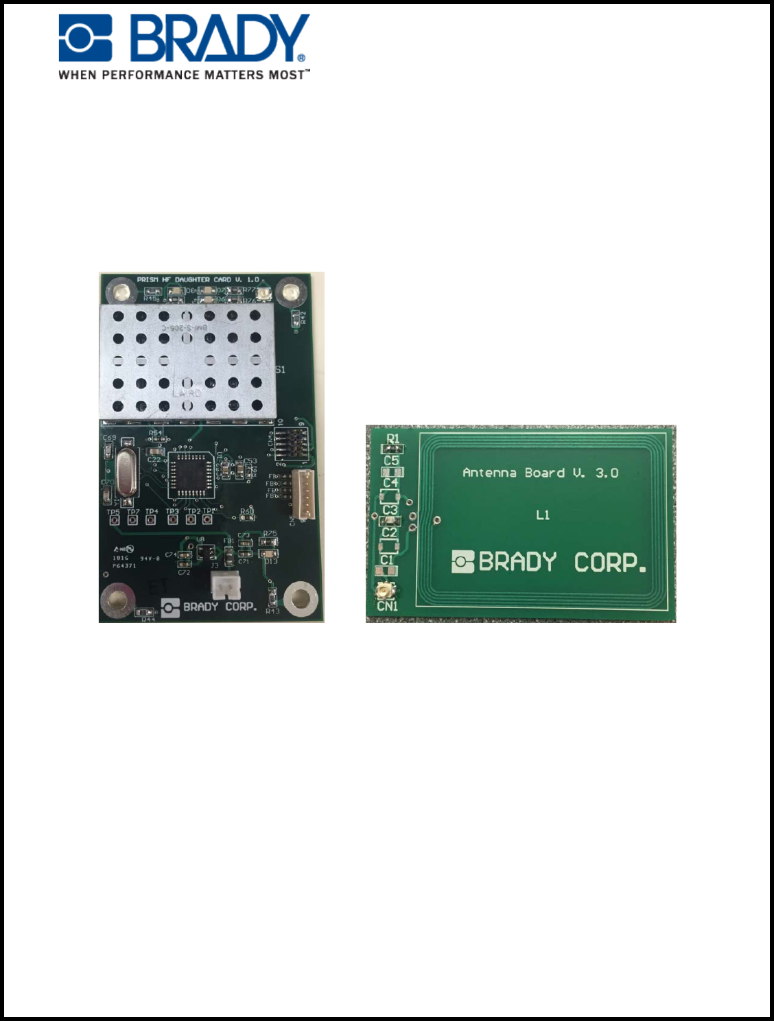
The Brady BDC2000 RFID Assembly consists of a Brady Daughter Card (BDC2000), a
PCB Antenna Board (ANT2000) and a U.FL cable connecting BDC2000 to the
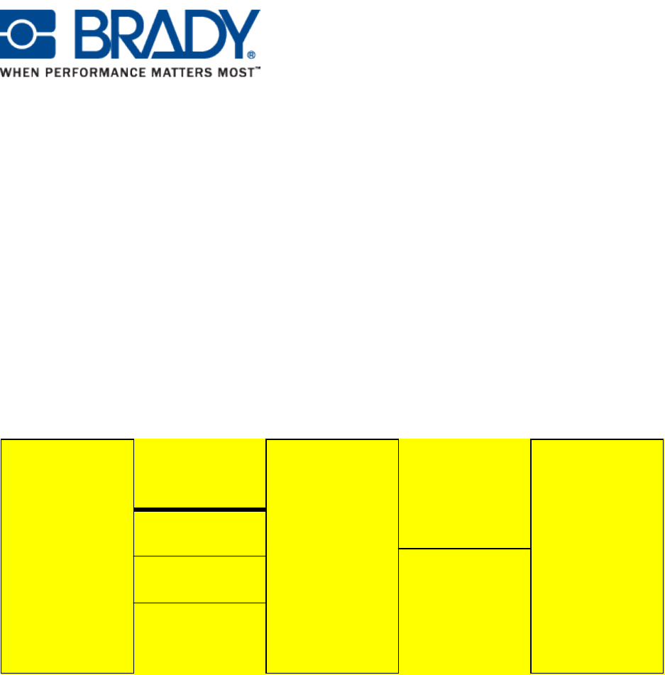
ANT2000 PCB. The diagram below shows the Brady BDC2000 RFID Assembly and its
connection to a host such as a printer’s main control board.
Host
Brady
Daughter
Card
Brady
Antenna
Board
SPI bus
5VDC
GND
U.FL cable
Host
Brady
Daughter
Card
Brady
Antenna
Board
SPI bus
5VDC
GND
U.FL cable
Figure 1. Block Diagram of Brady BDC2000 RFID Assembly and its Connection to a Host
The Brady BDC2000 RFID PCB has a radio module and MCU for control. The radio
module communicates to an HF RFID tag that is located in proximity to the ANT2000
antenna board. The information from the RFID tag can be acquired by the host through
the SPI bus. The host also provides 5VDC and ground to the BDC2000 RFID PCB.

9
1.2 Specification
The Brady BDC2000 RFID Assembly specification is provided in Table 1.
Table 1. Specification of Brady BDC2000 RFID Assembly
BDC2000 RFID PCB
Radio Fundamental Frequency 13.56 MHz
ISO Standard ISO 15693
Type of Modulation Amplitude
Antenna Type PCB Loop Antenna 50 OHM
Antenna Impedance 50 OHM
Number of Channels One
Operation Range (M) 0.05
Power Output RF power output < 200 mW
MCU ATSAMD21E17A
MCU XTAL 12 MHz
DC Voltage 5VDC +/- 10%
DC Current Consumption < 100mA
Communication Interface with Host SPI Bus
Operating Temperature Range 40 – 110 degF
Operating Humidity Range 20 to 80 % RH non-condensing
Size (mm x mm) 50 x 80
Weight (g) 18.5
ANT2000 PCB
Size (mm x mm) 40 x 60
Length of U.FL Cable (mm) Up to 203.2
Weight (g) 7
Gain (uH) 2.5 @ 13.56 MHz
10
2. Installation
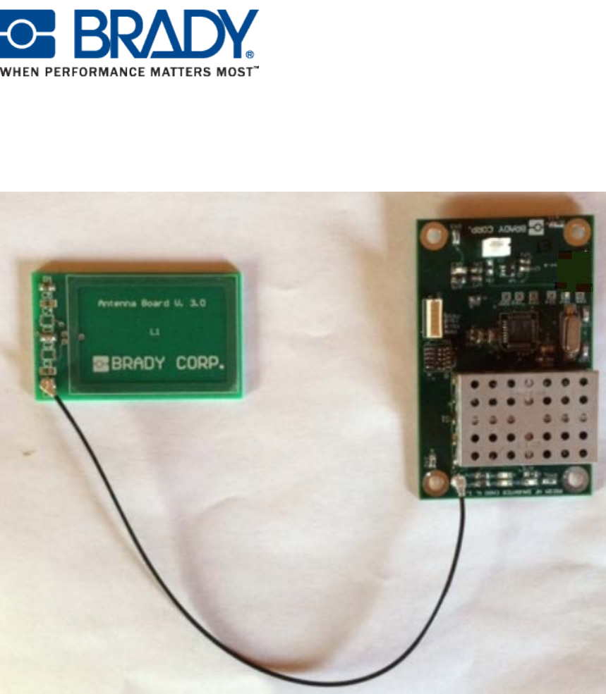
A photo of the Brady BDC2000 RFID Assembly is shown in Figure 2.
Figure 2. photo of the Brady BDC2000 RFID Assembly
As is shown in the picture, the Brady BDC2000 RFID PCB has four mounting holes at
the corners of the PCB. The holes’ center-to-center distances are 40mm and 70mm
respectively. The holes’ size is 4mm in diameter. These four holes can be used for
mounting the BDC2000 RFID PCB.
The Brady ANT2000 antenna PCB can be mounted with a custom plastic piece. A
cautionary note: The presence of metal in close proximity to the antenna loop will affect
the normal operation of the radio and should be avoided.

11
2.1 Connections
There are four connectors on the BDC.
• The U.FL connector for connecting a U.FL cable to the antenna board.
• The 6-pin JST B6B-PH-K-S connector for SPI, GND, and 5VDC.
• A separate 2-pin JST B2B-PH-K-S connector for 5VDC and GND.
• A dual row 10-position header (Samtec FTSH-105-01-L-DV) for debugging and
downloading firmware to the BDC2000 RFID PCB.
Note: The usage of the 2-pin connector is optional. If the 5VDC and GND are in the 6-
pin connector, then the 2-pin connector can be left unused.
The signal designations of the connectors are listed in Tables 2 to 4.
Table 2. JST B6B-PH-K-S
Pin Number
Signal
1
MOSI
2
SS
3
MISO
4
SCK
5
GND
6
5VDC
Table 3. JST B2B-PH-K-S
Pin Number
Signal
1
5VDC
2
GND
Table 4. Samtec 10-Position Dual Row
Pin Number
Signal
1
VTref (3V3)
2
SWDIO
3
GND
4
SWCLK
5
GND
6
SWO (NC)
7
NC
8
TDI (NC)
9
NC
10
nRESET

12
3.0 Operation
The Brady BDC2000 RFID PCB SPI configuration is shown in Table 5.
Table 5. BDC2000 SPI Configuration
Parameter
Setting
Clock Speed
100 KHz
Master/Slave
Slave
Number of Bits for Transmitting a Byte
8
Duplex
Full
Bit Direction
LSB (Little Endian)
SPI Transmission Mode
0 (Data latched at Rising Edge of the Clock)
The Brady BDC2000 RFID PCB acts as an SPI slave. It reads ISO15693 compliant tags
and converts and transmits the data to the SPI master upon request from the SPI master.
Firmware read out from the BDC2000 RFID PCB is inhibited. Attempting to read out
firmware will result in automatic erasure of flash program memory.
RFID configuration uses hard coded constants. Settings are locked down and are not
configurable.