Brady BEPM10 RFID External Programming Module User Manual Brady EPM User Guide
Brady Corporation RFID External Programming Module Brady EPM User Guide
UserManual.wiki
>
Brady
>
BEPM10 User Manual
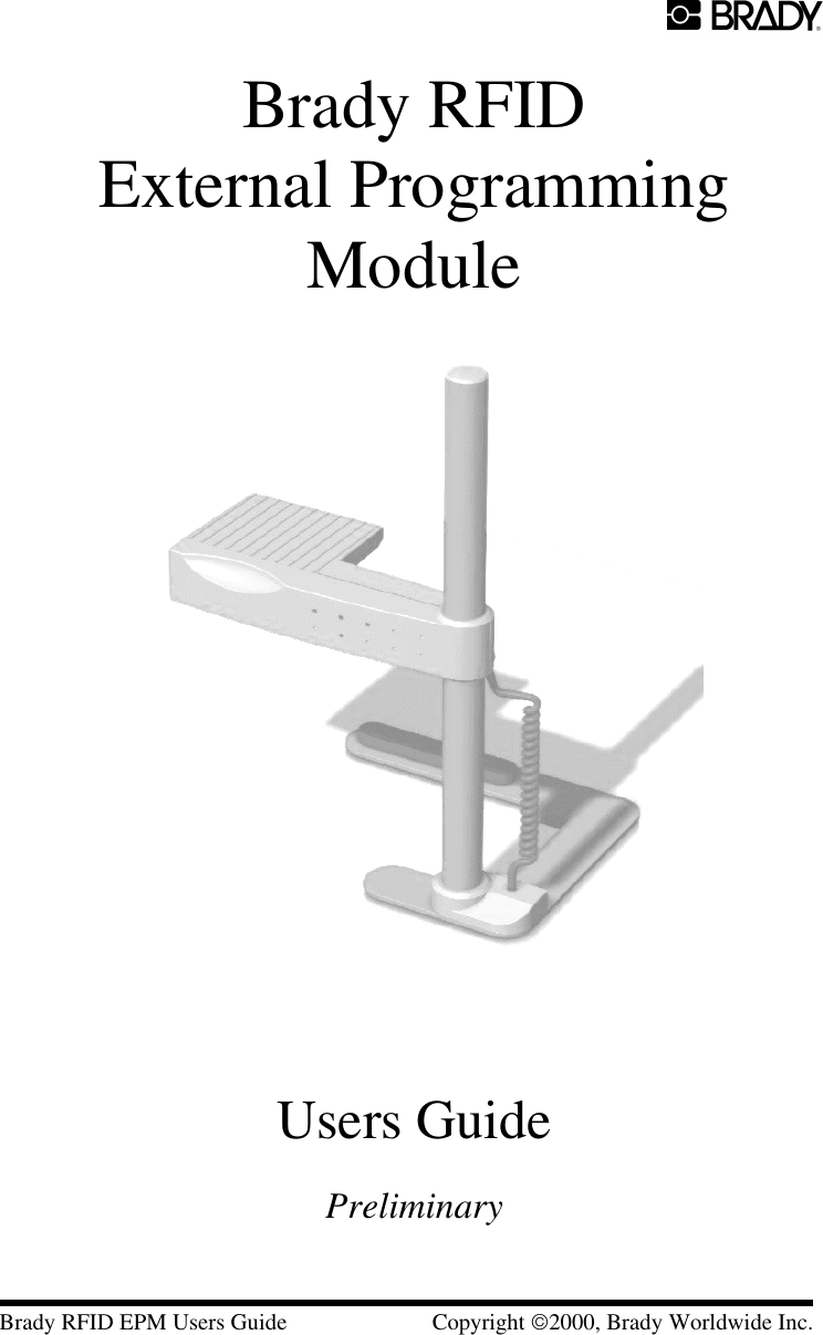
Users Guide
Navigation menu
Upload a User Manual
Namespaces
Wiki Guide
HTML
PDF
Info
Views
User Manual
Discussion / Help
Navigation