Braehler ICS Konferenztechnik DSPARK Radio Transceiver Unit User Manual BGE Digimic wireless 1 2
Braehler ICS Konferenztechnik AG Radio Transceiver Unit BGE Digimic wireless 1 2
User Manual
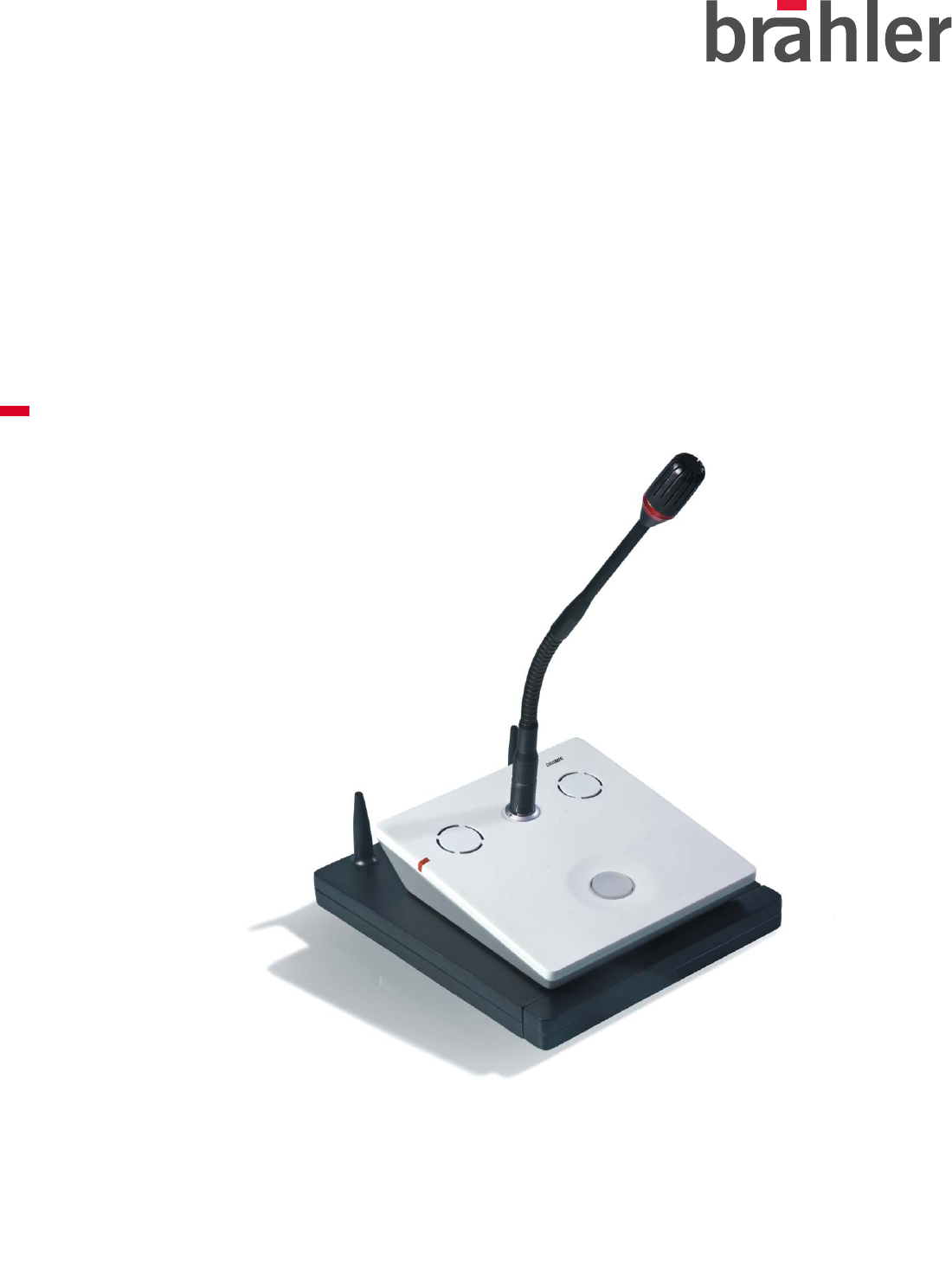
DIGIMIC®
Digital Discussion System - wireless
Operating instructions
Release 1.2

2
Printed in Germany
Should you have questions about this manual please contact:
Brähler ICS Konferenztechnik
International Congress Service AG
P.O. Box 3264
53627 Königswinter, Germany
T (0)2244 930-0
F (0)2244 930-450
E sales@braehler.com
www.braehler.com
© 2009 BRÄHLER ICS AG, Königswinter, Germany
All rights reserved, especially (also partly) the translation, reprint, reproduction through copying or other
similar methods.
BRÄHLER ICS reserves the right to make changes without notice.
Oct-09

3
Table of contents
About this manual.............................................................................................4
Symbols...................................................................................................................4
General information...................................................................................................4
Important information ........................................................................................ 5
Important safety instructions ......................................................................................5
Important safety information.......................................................................................6
DIGIMIC® Digital Conference System.................................................................... 8
Wireless system components......................................................................................8
Wired system components .........................................................................................8
CE Conformity and FCC Statement..............................................................................9
Autonomous mode.......................................................................................... 10
DSpark Radio Transceiver Unit............................................................................................11
Connecting the Power Supply ..........................................................................................12
Transmitting antenna .........................................................................................................13
Adjustment of the transmitting antenna ............................................................................13
Settings ...........................................................................................................................14
REGISTER......................................................................................................................15
HIGH POWER.................................................................................................................15
PRIOrity mode................................................................................................................15
LS INTERN.....................................................................................................................16
DDoc Docking Unit............................................................................................................17
Slave mode .................................................................................................... 19
Single operation mode ..................................................................................... 21
System startup .................................................................................................................21
DDoc Docking Unit............................................................................................................21
Indication of battery status..............................................................................................21
Automatic switch off......................................................................................................22
Charging of the battery pack...............................................................................................23
Charging via power supply...............................................................................................23
Charging via DTray Charging Tray ....................................................................................23
Removing the battery pack ..............................................................................................23
DTray Charging and Transport Tray .....................................................................................25
Multi room operation ....................................................................................... 26
Multi room operation mode examples...................................................................................26
Radio system number.........................................................................................................27
Adjusting DMic/DDoc combination to a room (0 – 4) .............................................................28
Resetting of DDoc Docking Units.........................................................................................28
Allocation of DDoc Docking Units........................................................................................28
Technical data ................................................................................................ 29
DSpark Radio Transceiver Unit............................................................................................29
DDoc Docking Unit............................................................................................................30
Appendix ....................................................................................................... 31
Block diagrams .......................................................................................................31
SERVICE FORM ......................................................................................................35
Contact information.................................................................................................37
About this manual
4
About this manual
Please keep this manual together with the system units. If you pass on the units to other parties, please
include this manual.
Symbols
The meanings of the symbols and fonts used in this manual are as follows:
Indicates an important note, if not minded, the functionality of the unit, the security of your data, or
your health are put at risk.
Supplementary information, remarks, and tips follow this symbol.
Text which follows this symbol describes activities that must be performed in the order shown.
Texts in bolded letters require your special attention.
General information
Please read the manual carefully, taking special care when you see this symbol as indicates
important information!
All brand names (marked with *) are registered trademarks of their respective owners.
The warranty invalidates, if you cause (generate, precipitate) inappropriate use or handling of the
unit.

Important safety instructions
5
Important information
Important safety instructions
• Read these instructions for use.
• Keep these instructions in a safe place.
• Heed all warnings.
• Follow all instructions.
• Do not use near water.
• Clean only with a dry cloth.
• Do not block any ventilation openings. Install in accordance with the manufacturer’s instructions.
• Do not install near any heat sources such as central heating radiators, electric heaters, stoves, or
other units that produce heat (e.g. amplifiers).
• This unit is supplied with an IEC mains cable complete with a molded mains plug. This is for your
safety – do not tamper with the mains. If the supplied cable does not fit your mains socket, please
consult a competent electrician for a replacement cable that matches the power output sockets in
your country, or to replace the obsolete socket with one to current standards.
• Protect the mains cable from being walked on or pinched, particularly at plugs, convenience
receptacles, and the point where it exits from the unit.
• Only use attachments/accessories specified by the manufacturer.
• Use only with the cart, stand, tripod, bracket, or table specified by the manufacturer, or sold with the
unit. When a cart is used, use caution when moving the cart/unit combination to avoid injury from tip-
over.
• Unplug during lightning storms or when unused for long periods of time.
• Refer all servicing to qualified service personnel. Servicing is required if the unit has been damaged
in any way, such as mains cable or plug damage, liquid has been spilled, objects have fallen inside,
the unit has been exposed to rain or moisture, does not operate properly or has been dropped.

Important safety information
6
Important safety information
Warning!
To reduce the risk of fire or electric shock, do not expose the unit to rain or moisture. Do not open
the unit as there are potentially dangerous voltages present inside. Refer all servicing to qualified
service personnel.
Caution!
Use only accessories recommended by the manufacturer to avoid fire, electric shock, or other
hazards. To prevent the risk of electric shock, do not remove cover or back. No user serviceable
parts inside! Refer all servicing to qualified service personnel.
Warning! Power source
The central control unit is a Class 1 unit. It must only be connected to properly grounded power
outlets. This unit should be operated only from the type of power source indicated on the marking
label.
lf you are not sure of the type of power supply to your building, consult your dealer or local power company.
Disconnection from the mains
To disconnect the unit from the mains, pull the mains plug out of the wall outlet.
Overload
Do not overload wall outlets and extension cables as this may result in fire and electric shock.
Objects and liquids
Never push objects of any kind through openings of this unit as they may touch dangerous voltage points or
short-out parts that could result in fire or electric shock. Never spill liquids of any kind onto the unit. Should a
spillage occur, unplug the unit and have it checked by a technician.
Maintenance and care
No user serviceable parts inside! Do not attempt to service this unit yourself as opening or removing covers
may expose dangerous voltage or other hazards. Refer all servicing to qualified service personnel.
Clean only with a dry cloth. Do not use detergents or other liquids.
Replacement parts
When replacement parts are required, be sure the service technician uses replacement parts specified by
the manufacturer or those that have the same characteristics as the original part.
Unauthorized substitutions may result in fire, electric shock, or other hazards.
Safety check
Upon completion of any service or repairs to this unit, ask the service technician to perform safety checks to
determine that the product is in proper operating condition.

Important safety information
7
The DIGIMIC conference system is state of the art and has been designed to meet the regulations in force.
Nevertheless, the individual components of the DIGIMIC conference system can cause danger for persons
and material assets if:
• the system is not used as intended,
• the system is set up by personnel not familiar with the safety regulations,
• the system is converted or altered incorrectly,
• the safety instructions are not observed.
Warning!
This system is capable of producing sound pressure exceeding 85 dB(A). 85 dB(A) is the sound pressure
corresponding to the maximum permissible volume which is by law (in some countries) allowed to affect your
hearing for the duration of a working day. It is used as a basis according to the specifications of industrial
medicine. Higher volumes or longer durations can damage your hearing. At higher volumes, the duration
must be shortened in order to prevent hearing damage.
The following are sure signs that you have been subjected to excessive noise for too long a time:
You can hear ringing or whistling sounds in your ears.
You have the impression (even for a short time only) that you can no longer hear high notes.
Disposal
This symbol on the product, in the instructions or on the packaging means that your electrical and
electronic equipment should be disposed at the end of its life separately from your household
waste. There are separate collection systems for recycling in the EU. For more information, please
contact the local authority or your retailer where you purchased the product.
Make sure to dispose of used batteries as required by local waste disposal rules.
Never throw batteries into a fire (risk of explosion) or dustbin.
When scrapping the equipment, remove the batteries, separate the case, circuit boards, and cables, and
dispose of all components in accordance with local waste disposal rules.

DIGIMIC® Digital Conference System
8
DIGIMIC® Digital Conference System
DIGIMIC stands for digitally controlled microphone management system. With DIGIMIC the digital age of
conference technology began. Technical advancements and user benefits defined DIGIMIC as a market
leader. DIGIMIC is used today throughout the world and in many regions it is a synonym for discussion
systems.
DIGIMIC set the standard for transmission quality, reliability, and compatibility. More importantly DIGIMIC
raised the bar regarding real value.
Brähler continues to lead with the introduction of the new DIGIMIC. Our new platform for conferencing
encompasses 50 years of experience and extraordinary innovation. With DIGIMIC it is no longer a question
of what to use but rather how to use it best. The wired system is upgraded to a wireless system by simply
adding the wireless docking unit whenever needed. It is a simple and elegant solution for both rental and
sales applications.
Simple, versatile, DIGIMIC!
The digital conference system provides a 100% stand alone solution and is completely self-configuring. With
DIGIMIC it is easier then ever before to setup even the most complex conference systems. True plug (and /
or unplugged) and play setup ensures that any microphone unit is operational instantly when connected.
DIGIMIC matches digital broadcast and studio audio requirements, meeting the needs of today’s
conferencing world. At any time the system can be expanded to include our conference software. TCP/ IP
communication is utilized to offer microphone control and name handling as well as other conference
requirements.
The delegate’s frontend – the microphone unit – offers a thoughtful ergonomic design enabling the delegate
to concentrate on the conference.
Wireless system components
• DSpark Radio Transceiver Unit
• DChair Chairperson’s Conference Unit
• DMic Delegates´ Conference Unit
• TMD/01 Conference Microphone
• TM58/6 Conference Microphone
• DDoc Docking Unit for DChair/DMic
• DTray Charging and Transport Tray
for 10 rechargeable batteries
• DPack Transport Case
for 10 DIGIMIC wireless units
• Antennas for DSpark Radio Transceiver Unit
Wired system components
• DCen Central Control Unit
• DChair Chairperson’s Conference Unit
• DMic Delegates´ Conference Unit
• TMD/01 Conference Microphone
• TM58/6 Conference Microphone
• D9 System cable

DIGIMIC® Digital Conference System
9
CE Conformity and FCC Statement
This equipment has been tested and found to comply with the limits of the European Council
Directive on the approximation of the member states relating to electromagnetic compatibility
(98/336/EEC) according to EN 55022 Class A.
This equipment has been tested and found to comply with the limits for a Class A digital device,
pursuant to Part 15 of the FCC Rules. These limits are designed to provide reasonable protection
against harmful interference in a residential installation. This equipment generates uses and can
radiate radio frequency energy and, if not installed and used in accordance with the instructions, may cause
harmful interference to radio communications. However, there is no guarantee that interference will not occur
in a particular installation. If this equipment does cause harmful interference to radio or television reception,
which can be determined by turning the equipment off and on, the user is encouraged to try to correct the
interference by one or more of the following measures:
• Reorient or relocate the receiving antenna.
• Increase the separation between the equipment and receiver.
• Connect the equipment into an outlet on a circuit different from that to which the receiver is connected.
• Consult the dealer or an experienced radio/TV technician for help.
NOTICE:
Changes or modifications made to this equipment not expressly approved by Brähler ICS Konferenztechnik
AG may void the FCC authorization to operate this equipment.
NOTICE:
This device complies with Part 15 of the FCC Rules and with RSS-210 of Industry Canada.
Operation is subject to the following two conditions:
(1) this device may not cause harmful interference, and
(2) this device must accept any interference received, including interference that may cause undesired
operation.
NOTICE:
This Class A digital apparatus complies with Canadian ICES-003.
Cet appareil numérique de la classe A est conforme à la norme NMB-003 du Canada.
Radiofrequency radiation exposure Information:
This equipment complies with FCC radiation exposure limits set forth for an uncontrolled environment. This
equipment should be installed and operated with minimum distance of 20 cm between the radiator and your
body.
This transmitter must not be co-located or operating in conjunction with any other antenna or transmitter.
Autonomous mode
10
Autonomous mode
The digital conference system provides a 100% stand alone solution and is completely self-configuring. With
DIGIMIC it is easier then ever before to setup even the most complex conference systems. DIGIMIC
matches digital broadcast and studio audio requirements, meeting the needs of today's conferencing world.
When connected to the DCen the system can be expanded to include our conference software. TCP/ IP
communication is utilized to offer microphone control and name handling as well as other conference
requirements. The delegate's frontend – the microphone unit – offers a thoughtful ergonomic design enabling
the delegate to concentrate on the conference.
DIGIMIC wireless can be used in different system modes as described in the following:
• Autonomous mode (also Multi-room mode, described in a separate chapter)
• Slave mode (please refer to page 19)
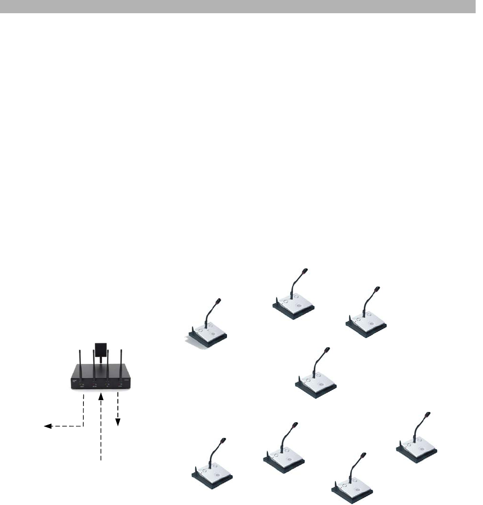
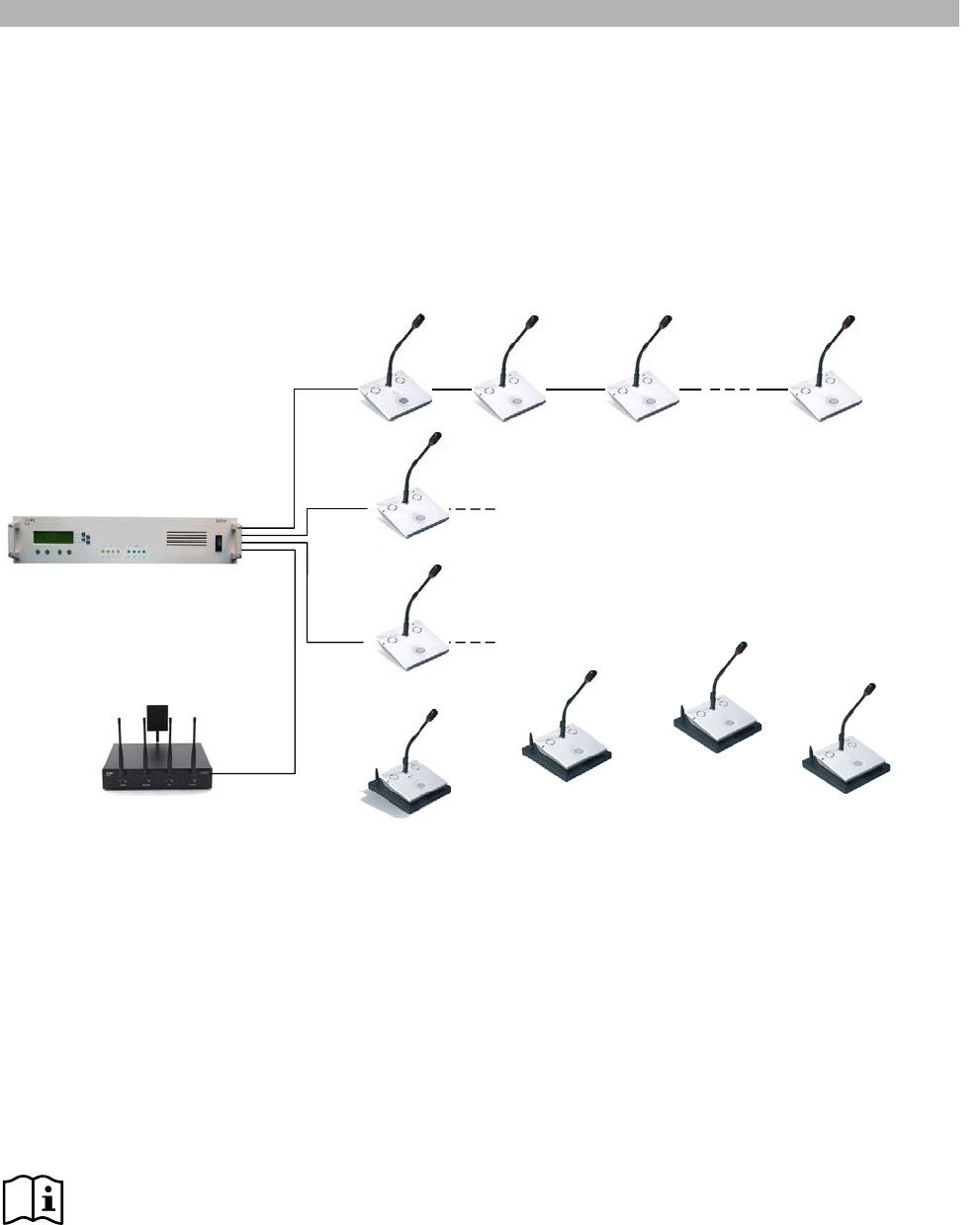
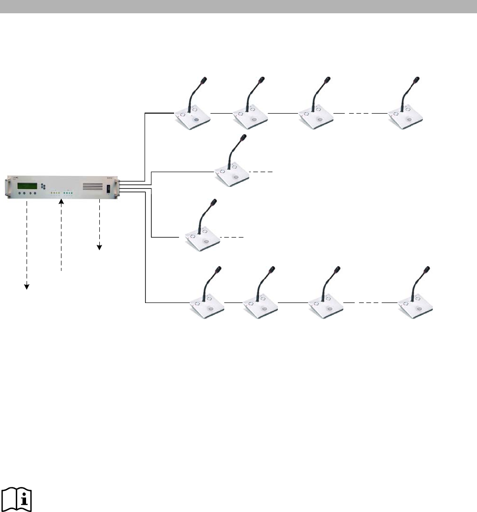
System overview wireless basic discussion system
Figure 1
TMD/01
o
r
TM58
/
6
External
Power
Supply
Wireless Delegate Units
DMic with DDoc
DSpark
Radio Transceiver Unit
Connection to
LS signal OUT
Connection to
ext . signal IN
Wireless Chairpersons’ Unit
DChair with DDoc
Microphone
Autonomous mode
11
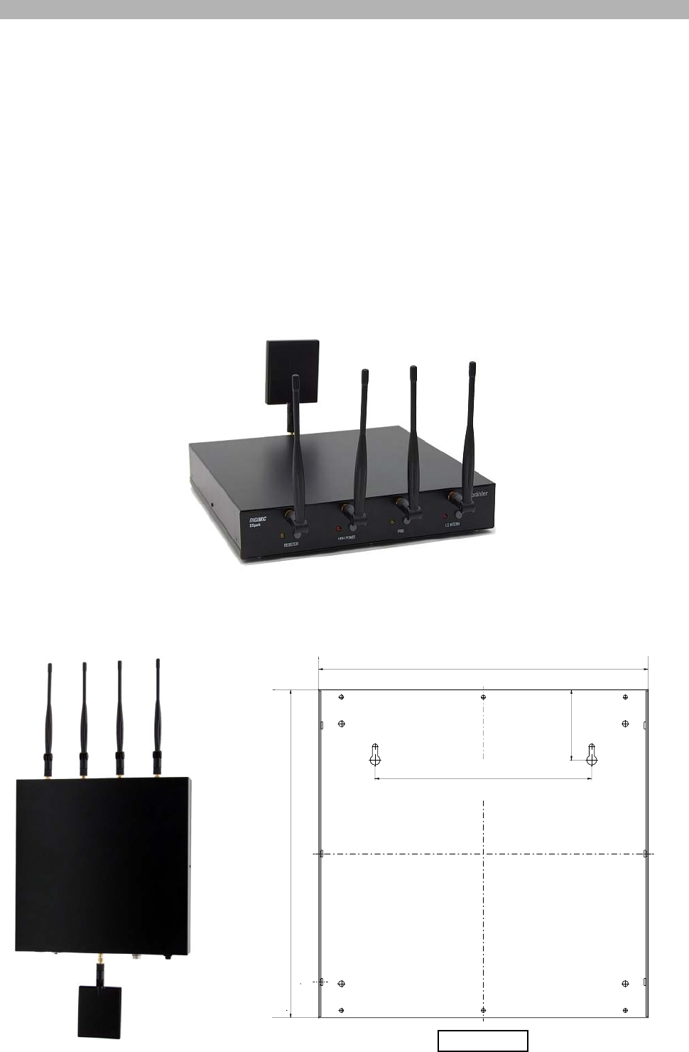
DSpark Radio Transceiver Unit
The radio transceiver unit DSpark together with the docking unit DDoc ensures reliable wireless audio
transmission.
For basic configurations the DSpark can be used autonomously offering the most common functionalities for
discussion systems. This solution offers an inexpensive first step into the wireless world of conferencing
without loosing the opportunity for future system upgrading and expansion, either wired or wireless.
The radio transmission is based on the unique intelligent adaptive narrow band protocol (APRON) which
combines for the first time ever several wireless transmission security features within one single protocol
ensuring co-existence with Wi-Fi systems and resistance to mobile phones or Bluetooth emission, also
suppressing unwanted interception.
The wireless DIGIMIC provides also a multi-room solution, offering the possibility of using the same system
within one building in several rooms at the same time.
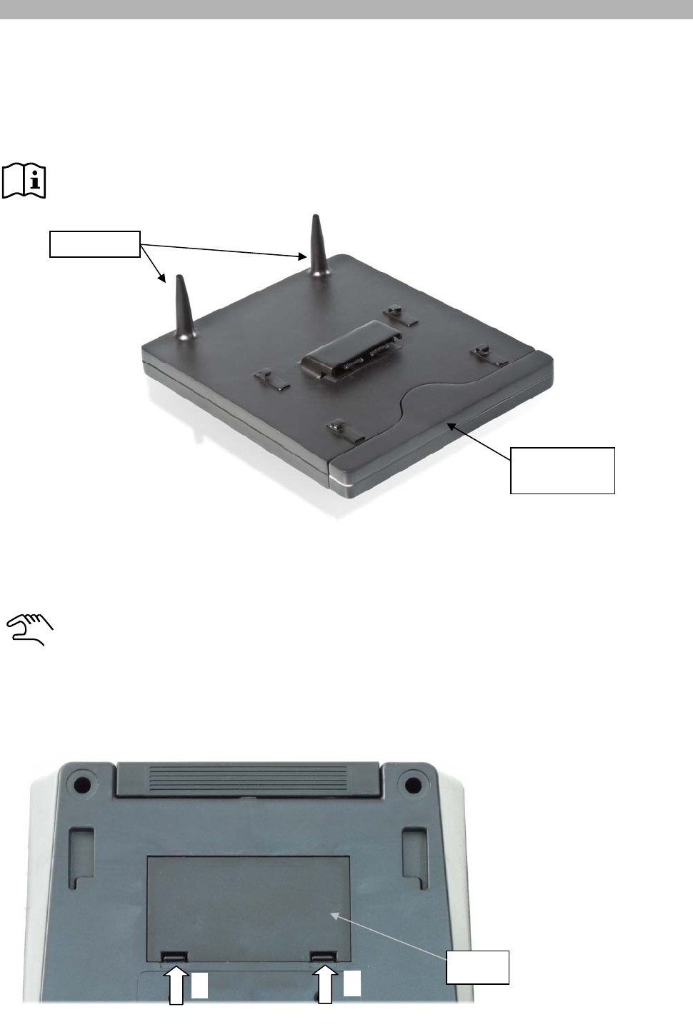
The DSpark is equipped with four independent antennas, receiving independently the individual signals of
each active microphone, providing a high audio quality and transmission reliability even under critical RF
congested environments.
The DSpark can also be wall mounted like shown in the next illustration. In this case also see HIGH POWER
in “Settings of DSpark” next chapter.
190 mm
7.48 in
289 mm
11.378 in
289 mm
11.378 in
62 mm
2.44 in
Rear side
Autonomous mode
12
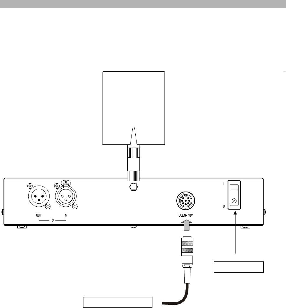
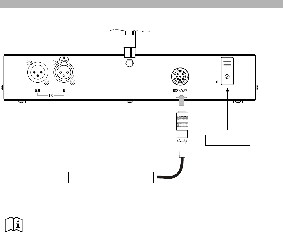
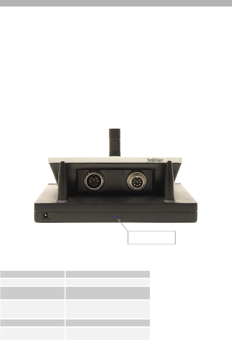
Connecting the Power Supply
For the basic functions of the Radio Transceiver Unit you just have to connect the external desktop power
supply to the DSpark (Figure 2).
Then you can start to place the wireless delegate units DMic with DDoc for your conference.
Figure 2
Power Supply 05.0292
On/Off switch
Autonomous mode
13
Transmitting antenna
The powerful directed transmission antenna ensures the continuous control and audio downstream to each
single delegate unit within the system even over longer distances of up to 50m radius and beyond,
depending on the installation environment.
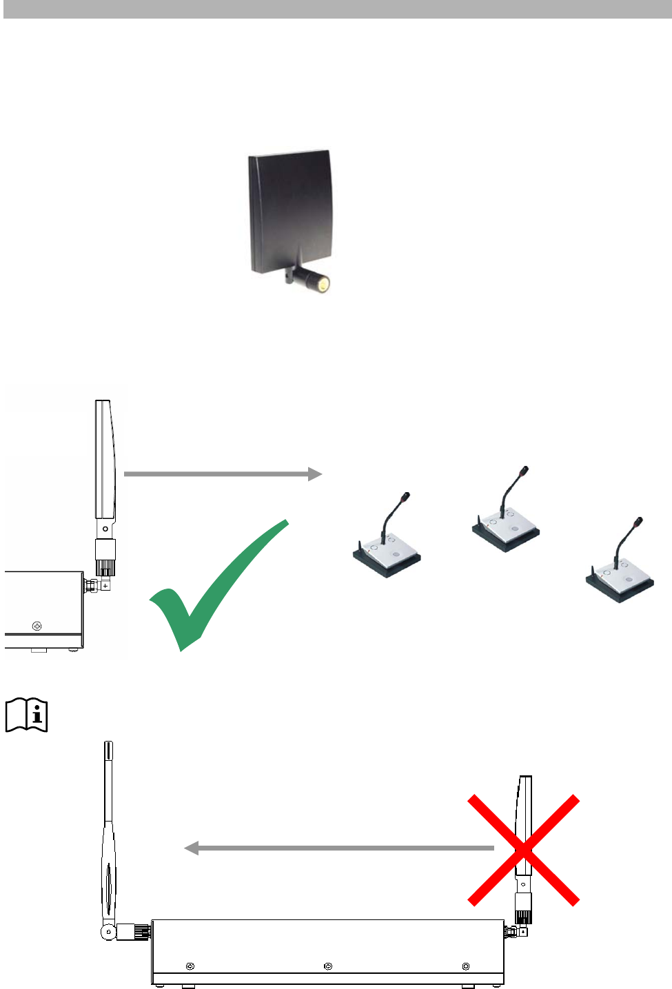
Adjustment of the transmitting antenna
The radiating side of the transmission antenna is the curved front side. This side must be adjusted toward
the room/microphone units.
To avoid interference it is not recommended to adjust the front side of the transmitting antenna
toward the receiving antennas.
antenna
front
antenna
back Direction of signal radiation
Direction of signal radiation
Autonomous mode
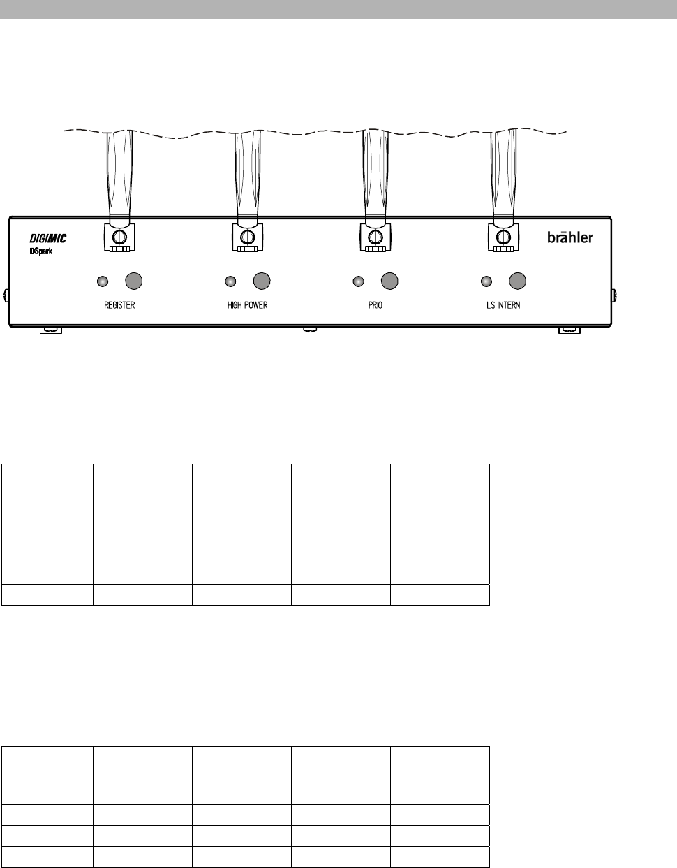
14
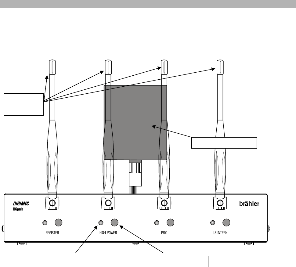
Settings
All functions are activated when pressing the corresponding push-button. The corresponding control LED will
light up when a function is activated.
Figure 3
For basic configurations the DSpark can be used autonomously offering the most common functionalities for
discussion systems like AUT3 or PRIO.
Control LED Push-button for activation
Transmitting antenna
Receiving
antennas

Autonomous mode
15
REGISTER
REGISTER can be opened (LED off) or closed (LED on).
Use REGISTER open (LED off) during setup.
During setup you switch on and register your units to the DSpark. The DSpark will automatically put all
recognized units into an internal list. This list will be expanded as long as the register function is open (LED
off).
To save this list close the Register (LED on). Once the register is closed no more units can be registered to
the DSpark. This function offers you the following opportunities:
1. The wireless system is now completely closed (like a wired one) and cannot be intercepted by any
other wireless DIGIMIC unit. This is important because to exclude interception you have to take out
the unit which are designed to work perfectly with the DIGIMIC wireless: DMic and DDoc.
2. This register function also enables to use multiple DIGIMIC wireless systems within one building by
simply assign your units to the DSpark of the corresponding room (please refer to page 26 for more
details)
Note: The list is stored automatically.
To delete the list press and hold button “register” for minimum 5 seconds. The corresponding LED
will flash two times to indicate that the list is deleted.
Note: You can exchange the battery pack and re-register the units which had already registered
even when the register is closed.
HIGH POWER
With this option the power of sending is increased in the case DSpark is used as desktop. When DSpark is
wall mounted, there is no need of increasing the output power.
PRIOrity mode
If a DChair unit is to be used, PRIO mode is available with this setting. Press button PRIO to enable this
option. Maximum 2 DChair units are supported as chairpersons at the same time. They will be identified
automatically. With 2 DChair units 2 active Delegate units DMic are possible at the same time.
This means:
0 DChair Æ max 4 active delegates’ are possible
1 DChair Æ max 3 active delegates’ are possible
2 DChair Æ max 2 active delegates’ are possible
Autonomous mode
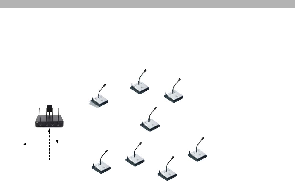
16
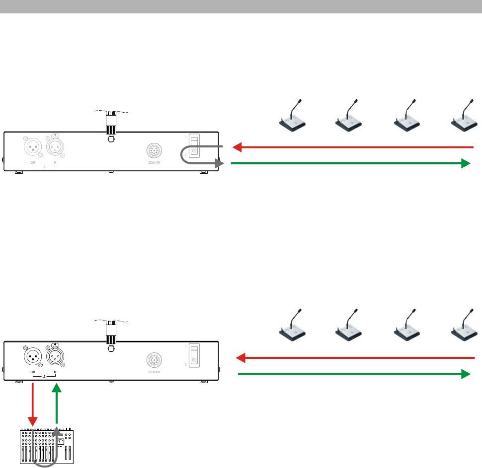
LS INTERN
When active (LED on) the audio signals from the DMic units are directly routed to the DMic loudspeakers.
Audio from DMic micro
Audio to DMic loudspeakers (LS)
Figure 4
Otherwise (LED off) external signals are routed to the DMic loudspeakers, e.g. from a mixing console like
shown below.
Audio from DMic micro
Audio to DMic loudspeakers (LS)
Figure 5
DDoc Docking Unit
17
DDoc Docking Unit
The docking unit DDoc transforms the delegate unit DMic into a wireless discussion unit, replacing the tasks
of a cable by its powerful rechargeable battery and the reliable and stable wireless communication protocol.
DMic and DChair are delivered with a cover to protect the contact bar.
Before using the DDoc the first time we recommend to check or charge the rechargeable batteries.
(please refer to page 23)
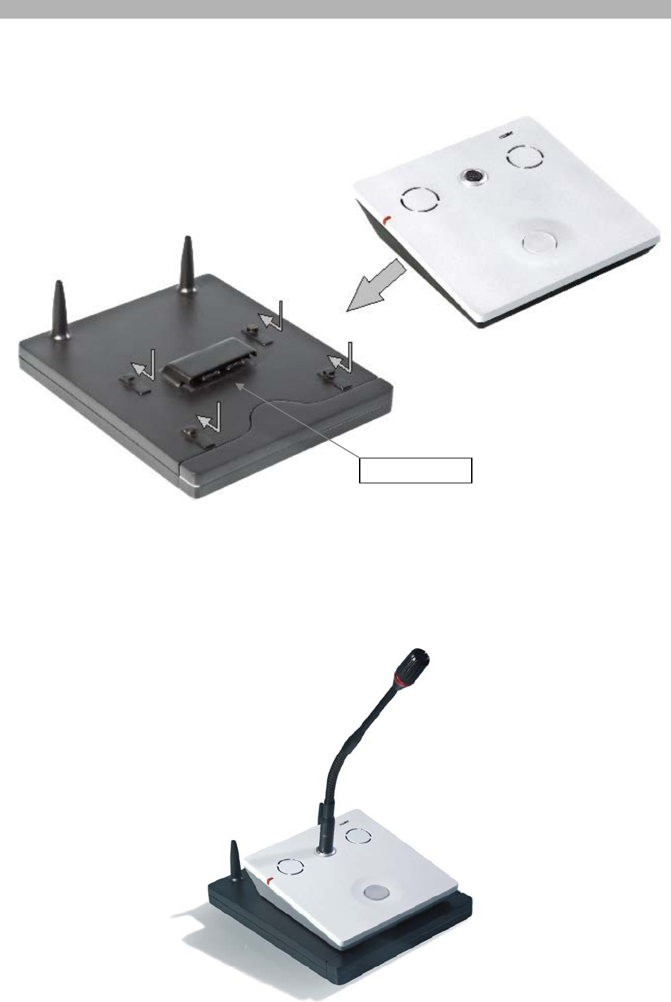
The transformation of the wired DIGIMIC delegate units is easily be done by unplugging the cable and sliding
the DMic on the docking station DDoc.
But before sliding the DMic on the docking station, it is necessary to remove the covering of the
contact bar on the rear side. This is done in the way shown below:
1. Turn the DMic upside down, if there is no microphone plugged in. We recommend
handling on a soft surface.
2. Press the two clips in the shown direction.
3. Turn the DMic on top, the covering should fall down.
Rechargeable
battery pack
Antennas
2.
2. Cover
DDoc Docking Unit
18
Slide the DMic on the docking station DDoc.
Ensure that the unit is connected properly with the contact bar.
This solution introduces unique flexibility in terms of the installation of rental and sales projects and
maintains a high level of connectivity. DIGIMIC wireless is based on an intelligent transmission protocol,
which assures the audio quality and reliability of a wired conference system, combined with the flexibility and
freedom offered by wireless.
The complete DMic Delegates Conference Unit with the DDoc Docking Unit looks like shown below. Don’t
forget to assemble the microphone.
DMic
DDoc Contact bar
Slave mode
19
Slave mode
For additional discussion functions, like Request-to-Speak-mode, name handling, robotic camera control,
software interfaces or combination with wired units the DSpark can be connected easily to the DIGIMIC
central control unit DCen. Only in this mode DDoc can be set into standby.
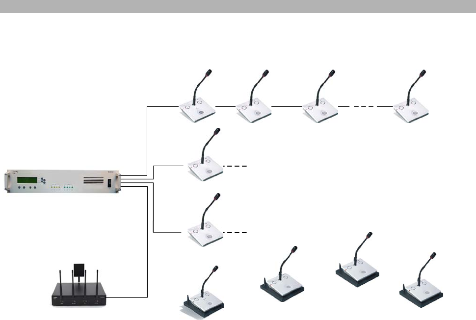
Configuration of slave mode together with wired units
Wireless Delegate Units DMic/DChair with DDoc
TMD/01
or
TM58/6
Wired Delegate Units DMic/DChair
D9 cable D9 cable
D9 cable
D9 cable
DSpark
Radio Transceiver Unit
DCen
Central Control Unit
D9 cable
TMD/01
or
TM58/6
Connections see product information
Connections see product information
Figure 6
The connection to the DCen Central Control Unit is done by the D9 system cable used for the wired delegate
units DMic.
Once connected to the DCen, the DSpark falls automatically into the Slave Mode. All registered wireless
DIGIMIC discussion units will be controlled now only by the DCen Central Control Unit and behave just like
another line of wired discussion units. The D9 system cable is a high flexible shielded CAT5 cable with
lockable S8G-connectors.
Note: The DSpark Radio Transceiver Unit will switch over automatically into Slave Mode if it is connected
to a DCen Central Control Unit. In this case no settings are possible at the DSpark. The DIGIMIC
discussion units will be controlled now only by the DCen Central Control Unit and also all settings
will be made here.
Microphone
Micro
p
hone
Slave mode
20
Figure 7
For detailed operating description of the DCen Central Control Unit please refer to the manual
“DIGIMIC digital discussion system - wired”.
D9 cable from DCen (LINE)
On/Off switch
Single operation mode
21
Single operation mode
The following chapter describes the operation with one DSpark in autonomous mode.
System startup
Before starting a conference all units have to be registered by the Radio Transceiver Unit DSpark. This is
easily done by just pressing the microphone key. Please ensure that the REGISTER LED is off. Successful
registration will cause the microphone ring and microphone button to flash twice.
DDoc Docking Unit
Before starting operation with the DIGIMIC wireless equipment make sure that the rechargeable batteries
inside the DDoc units are properly charged. Otherwise the battery pack has to be charged, either in the
DTray (Charging and transport tray for 10 DDoc) or with an external power supply.
For successful login status see table below.
Indication of battery status
There are three possibilities of checking the status of the rechargeable batteries:
1) In operation Æ by a Multicolor-LED in front of the docking station.
The Multicolor LED has different indication modes:
White – for a few seconds ready for operation
BLUE – flashing no reception, battery ok
BLUE – not flashing radio reception ok, battery ok
(more than 1h operation time)
OFF – permanent Switches off automatically after 30
sec for power saving
(standard operation mode)
RED – not flashing radio reception ok, battery low
RED – flashing no reception, battery low
(for less than 1h operation time)
Multicolor LED
Single operation mode
22
Easy rule to remember:
Mode flashing or permanent Æ receiving status
Color red or blue Æ status of rechargeable batteries
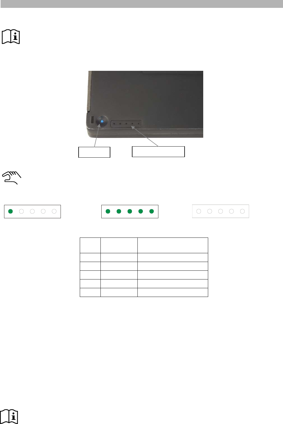
2) Not in operation Æ by a test key at the bottom of the battery pack.
Press and hold the blue test key with a peaked object or your fingernail. The green LEDs will then
indicate the current battery status in 20% increments.
For example:
Low battery power > 80% battery power Full battery, end of charging
LEDs
on Battery
power Operating time
1 * 20% up to 4h
2 20 – 40% up to 8h
3 40 – 60% up to 12h
4 60 – 80% up to 16h
5 80 – 100% up to 20h
* If one LED is flashing, the battery is almost empty.
3) Not in operation Æ by charging in the DTray charging tray.
The status indication of the battery power is the same as shown above. The LED indication by charging the
docking unit in the DTray is permanently, so you don’t have to push the test key for this purpose.
Automatic switch off
The DDoc switches off automatically, if:
- the DMic will be disconnected from DDoc (immediately switching off)
- the battery pack is removed from the DDoc unit
- a switch off signal arrives from the DSpark (immediately switching off)
- there is no radio communication for 30 seconds (e.g. outside the radio range)
- the battery is empty
Note: If you switch off the DSpark radio transceiver unit, all registered DMic / DDoc units will switch
off immediately.
Test key Indicator lights
Single operation mode
23
Charging of the battery pack
There are two options of charging the battery pack.
Charging via power supply
For a quick charging of a single unit an external power supply (05.0902) is provided. You do not need to
remove the battery pack from the DDoc. Just connect the plug to the connector of the DDoc.
Note: The discussion function of the unit is disabled when the external power supply is connected.
Charging with the external power supply is only possible if the unit is not in use.
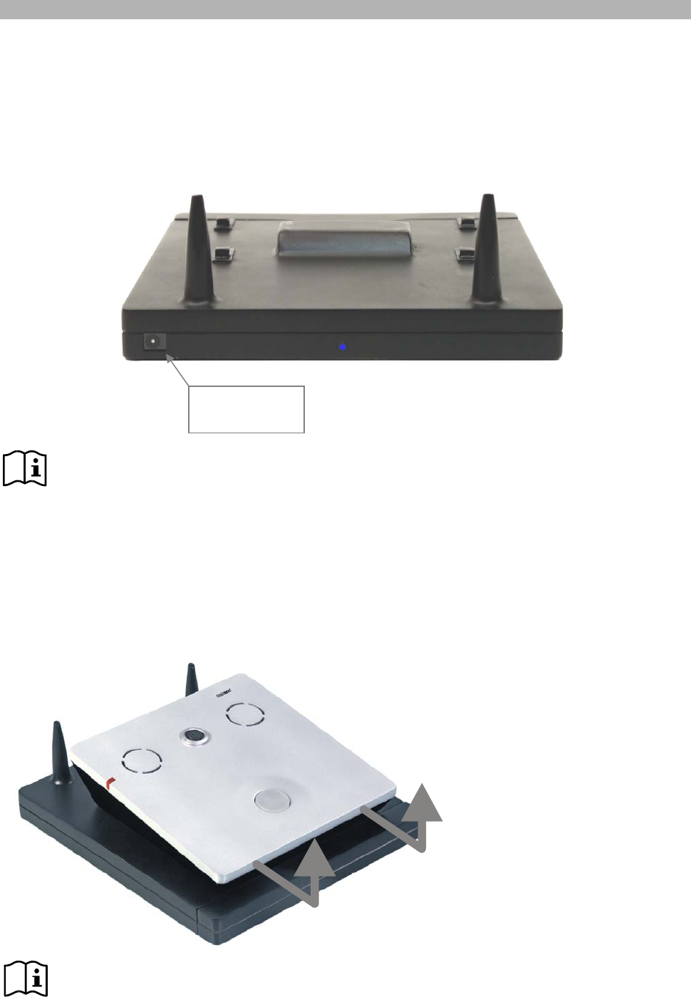
Charging via DTray Charging Tray
For charging more than one battery pack an external Charging Unit DTray is provided. With DTray it is
possible to charge 10 units at once. First you have to remove the battery pack from DDoc.
Removing the battery pack
No tools are necessary to remove the battery pack. If not already done, separate the DMic unit from the
DDoc docking unit as shown below.
Note: This charging solution offers you the opportunity to leave all units on the tables in your
conference room. Just collect all batteries after the conference day to re-charge them.
You also can just exchange low batteries (during conference) with charged one’s offering the
possibility of an “unlimited” wireless conference period.
Connector for
power supply
Single operation mode
24
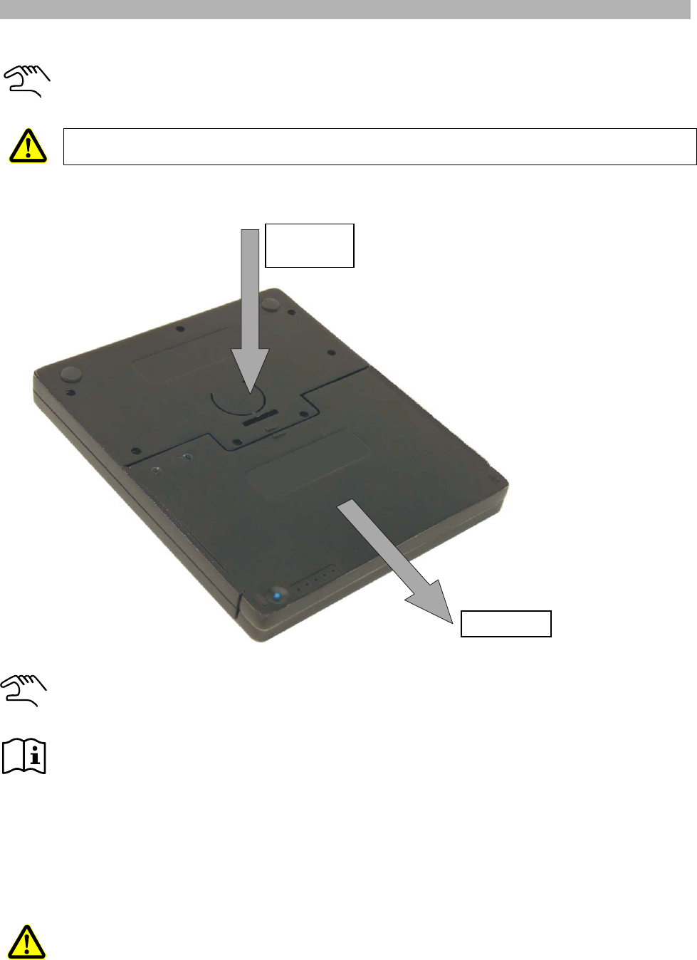
To remove the rechargeable battery pack, pick up the DDoc and turn it upside down, press the
marked position and pull as shown:
Never under any circumstances place the DDoc unit upside down on a table or something else.
This can damage the antennas!
Insert the battery pack into a free slot of the DTray charging tray.
The charging time is max. 9 hours if the battery is completely empty.
Specifications of the battery pack:
• Lithium polymers (built in)
• 3.7 VDC
• 13.2 Ah
Please be sure to avoid a short circuit of the electrical connections.
To put back the battery pack after charging simply slide it back in the DDoc. The sophisticated design of the
DDoc ensures that the battery pack is slide in always correctly.
1
2
Press and
hold here
Pull here
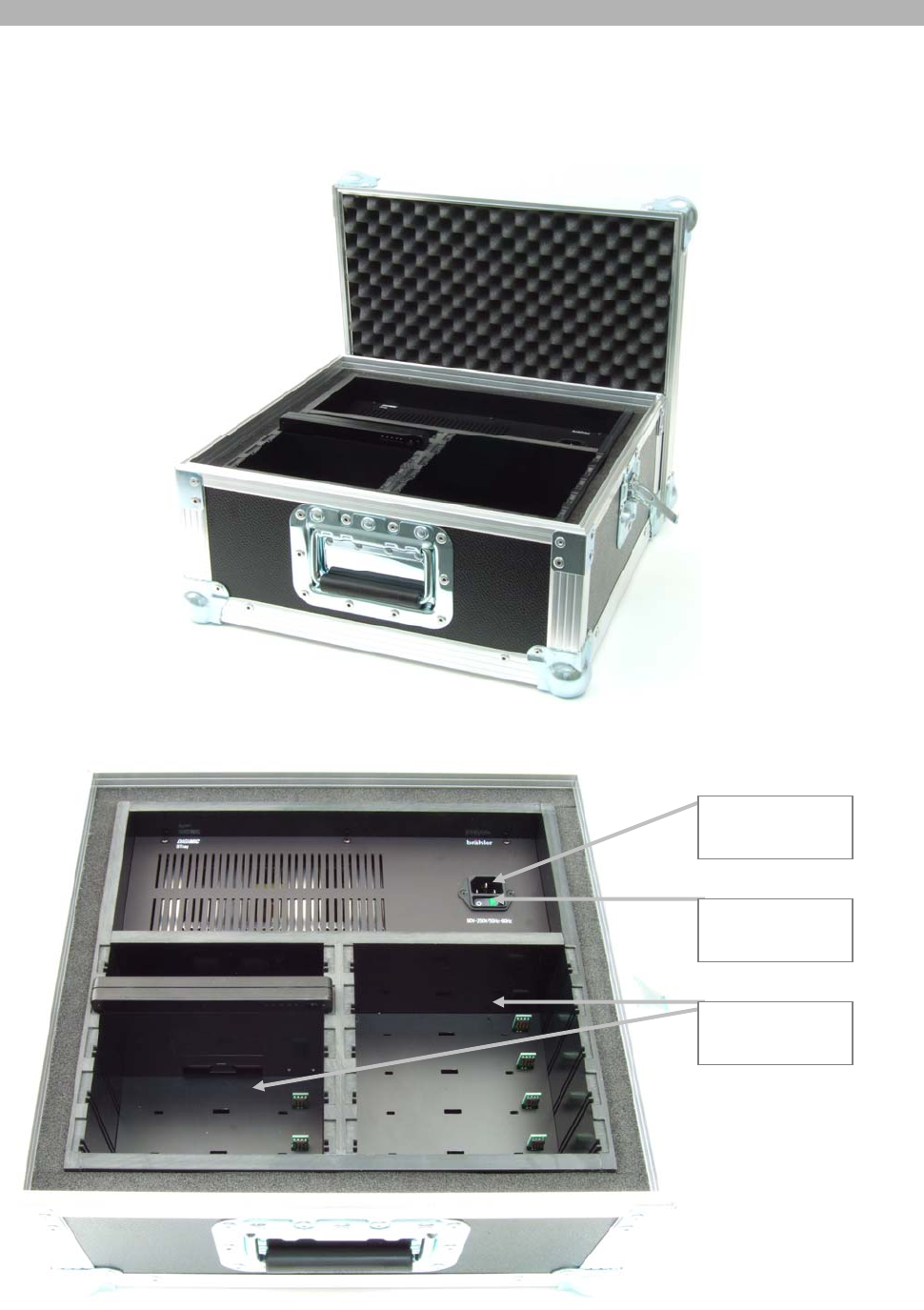
DTray Charging and Transport Tray
25
DTray Charging and Transport Tray
DTray is a charging and transport tray for 10 rechargeable DDoc batteries. It is equipped with a switching
power supply 85-240VAC.
Mains
connector
Mains switch
10 Slots for
battery pack
Multi room operation
26
Multi room operation
The following chapter describes the operation in autonomous mode with more than one DSpark. Multi
operation mode is also available for slave mode in combination with DCen (wired central unit). The setup
procedure is the same.
With DIGIMIC wireless it is possible to handle parallel operation of different conferences in the immediate
vicinity. To enable a reliable operation each DSpark has to be configured with its own ID. Up to 5 radio
channel numbers (0 to 4) are possible.
Note: channel #0 is factory default
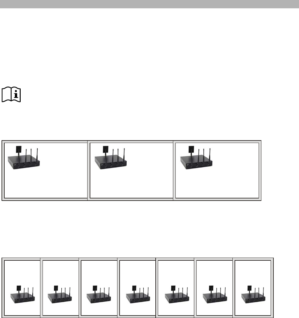
Multi room operation mode examples
a) Parallel operation with 3 DIGIMIC wireless systems in three conference rooms:
Room 1 Room 2 Room 3
radio system
number 0 radio system
number 1 radio system
number 2
This sample enables a reliable and autonomous operation.
b) Parallel operation with more than 3 DIGIMIC wireless systems in seven rooms:
Room 1
radio system
number 0
Room 2
radio system
number 1
Room 3
radio system
number 2
Room 4
radio system
number 3
Room 5
radio system
number 4
Room 6
radio system
number 0
Room 7
radio system
number 1
This constellation enables also a reliable and autonomous operation. Please notice that room 6 has the
same radio system number than room 1. It is essential that there is a greater distance to room 1.
Multi room operation
27
Radio system number
For allocation of another channel number press the keys REGISTER and LS INTERN of the DSpark Radio
Transceiver Unit simultaneously. This will enter the configuration mode.
Figure 8
DSpark confirms this mode by blinking two times of all 4 LEDs (REGISTER + HIGH POWER + PRIO +
LS INTERN). The current radio channel number is displayed.
The pattern of the LEDs is shown in the table below:
logical radio
number LED
REGISTER LED HIGH
POWER LED PRIO LED LS
INTERN
0 off off off off
1 on off off off
2 on on off off
3 on on on off
4 on on on on
Table 1
Now the user can specify the new logical radio number by setting the LEDs with the corresponding buttons
on or off. It is insignificant which LEDs are switched, or in what order this happens. Only the number of LEDs
lucent is relevant as input for the new radio system number.
Examples for valid input of radio system number 2:
logical radio
number LED
REGISTER LED HIGH
POWER LED PRIO LED LS
INTERN
2 on on off off
2 off off on on
2 off on off on
2 off on on off
Five seconds after pressing any button the configuration mode is finished. This is indicated by blinking two
times of all 4 LEDs (REGISTER + HIGH POWER + PRIO + LS INTERN). The new radio system number is
now saved will be used until this setting is changed again.
Also the primary status of the LEDs and the function of the buttons are restored. The new settings are
immediately effective; there is no need to switch DSpark on and off.
If no changes are made in configuration modus the current setting persists when leaving the configuration.
Therefore this procedure can be used to show the current setting of the radio system number.
factory default

Multi room operation
28
Adjusting DMic/DDoc combination to a room (0 – 4)
Please make sure only one DSpark in your venue has activated the register function (register open –
LED OFF).
Please make sure that the preset of the several DSpark Radio Transceiver Units is like described above.
Open Register (LED OFF) on your first DSpark (Local radio channel number 0). Make sure other DSpark
have their Register closed (LED on). Place the desired number of units on the table and press the MIC
button one after each other.
Resetting of DDoc Docking Units
DSpark can reset all docking stations DDoc which are allocated to this DSpark (Radio Transceiver Unit) and
are in operating distance. Therefore press the inner buttons HIGH POWER and PRIO simultaneously for
about 5 seconds. The LEDs of HIGH POWER and PRIO are flashing for the time of deleting, but minimum
three times.
If you do this, all DDoc units will forget the room number they were tied to. This requires a new setup.
Allocation of DDoc Docking Units
To configure the DDoc units press and hold the MIC button for at least 4 seconds. This procedure is
indicated by flashing of the multi MIC-LED. The current radio channel number is reset. In this mode DDoc
searches for any DSpark Radio Transceiver Units. If one is recognized DDoc tries to log in. When successful
DDoc gets confirmation and stores the new radio channel number as default.
This will finish the configuration mode.
If there is no log-in possible DDoc will terminate the configuration mode after 30 seconds and then switch off.
When all microphones are working (successful login) a quick microphone test is recommended. Close the
Register (LED ON). After this you can go to the second room and perform the same procedure with a
DSpark assigned to the next room (local radio number 1).

Technical data
29
Technical data
DSpark Radio Transceiver Unit
HF Properties
Kind of Modulation FSK, FHSS
Frequency Range 2400-2480 MHz
Quality of Service (QoS) Predictive & Adaptive Frequency Hopping Algo (PFH & AFH)
Receiver Sensitivity < - 81 dBm at 10-3 BER
Number of Channels 38
Channel Spacing (minimal) 2.048 MHz
Channel Bandwidth (20 dB) < 2 MHz
Frequency Stability 10 ppm
Number of RF Paths 1 x TX, 4 x RX
Antenna RX Path Swivel omni-directional antennas (4.5 dBi)
Antenna TX Path Swivel directional panel antenna (6 dBi)
Alternative: External directional panel antenna (12dBi)
connection with special coax cable (min. length 6m)
RF Power Out (EIRP) typ. 19 dBm (max. < 20 dBm)
RF Range typ. 400 m (free space range)
Digital Audio Frequency Characteristics
Digital Audio Resolution 16 Bit
Sample Rate 48 kHz
End to End Latency 5-13 ms
Analog Audio Frequency Characteristics
AF Range 20 Hz - 20 kHz
Harmonic Distortion < 0.1 %
SNR + Noise typ. 78 dB(A)
Analog Input / Output Characteristics
Audio Input Nominal Level (-9 dBFS) 1.22 V (= +4 dBu)
Audio Output Nominal Level (-9 dBFS) 1.22 V (= +4 dBu)
General Properties
Temperature Range 0°C to +50°C (with connection to DCen)
0°C to +40°C (with external power supply 05.0292)
Power Supply Voltage 24 - 48 VDC
Current Consumption typ. 185 mA
Dimensions (without antennas) ca. 290 mm x 56 mm x 290 mm (W x H x D)
Weight (incl. antennas) ca. 2.8 kg
In Accordance with standards ETS 300 445, ETS 300 422, FCC Part 15.247, FCC Part 15B,
FCC 15_209, FCC 15_407, EN 61000-6-1, EN 61000-6-3,
EN 61000-4-3, EN 55022, EN 300328, EN 301489-1/-17,
IEC/EN 60065, CISPR22.

Technical data
30
DDoc Docking Unit
HF Properties
Kind of Modulation FSK, FHSS
FSK Raw Data Rate 1.536 Mbits/s
Frequency Range 2400-2480 MHz
Quality of Service (QoS) Predictive & Adaptive Frequency Hopping Algo (PFH & AFH)
Receiver Sensitivity < - 81 dBm at 10-3 BER
Number of Channels 38
Channel Spacing (minimal) 2.048 MHz
Channel Bandwidth (20 dB) < 2 MHz
Frequency Stability 10 ppm
Number of RF Paths 1 x TX, 1 x RX
Antenna Quarter wave length monopole antenna (one for each RF Path)
RF Power Out (EIRP) typ. 19 dBm (max. < 20 dBm)
RF Range typ. 400 m (free space range)
Digital Audio Frequency Characteristics
Digital Audio Resolution 16 Bit
Sample Rate 48 kHz
End to End Latency 5-13 ms
Analog Audio Frequency Characteristics (in combination with DMIC)
AF Range 20 Hz - 20 kHz
Harmonic Distortion < 0.1 %
SNR typ. 78 dB(A)
Analog Input / Output Characteristics (in combination with DMIC)
Microphone Input Nominal Level typ. 8 mV
Loudspeaker Output Nominal Level - 8 dB
Headset Output Nominal Level 0 dB
General Properties
Temperature Range -10°C to +55°C
Accumulator Voltage 3.0 - 4.1 VDC, nominal 3.7 VDC
Power Supply Voltage 7.5 VDC
(battery charging)
Current Consumption typ. 550 mA (RX) / 740mA (TX) in combination with DMIC
Standby Current Consumption < 1 µA
Dimensions (W x H x D) ca. 161 mm x 60 mm x 189 mm
Weight (incl. accumulator) ca. 550 g
In Accordance with standards ETS 300 445, ETS 300 422, FCC Part 15.247, FCC Part 15B,
FCC 15_209, FCC 15_407, EN 61000-6-1, EN 61000-6-3,
EN 61000-4-3, EN 55022, EN 300328, EN 301489-1/-17,
IEC/EN 60065, CISPR22.
Appendix
31
Appendix
Block diagrams
DIGIMIC wireless
Components:
DSpark Radio Transceiver Unit
DChair Chairpersons´ Conference Unit
DMic Delegates´ Conference Unit with Microphone
DDoc Docking Unit with rechargeable battery
DTray Storage / Charging tray
TMD/01 Conference Microphone, electret
TMD/01
or
TM58/6
Connection to
external power
supply
Wireless Delegate Units
DMic with DDoc
DSpark
Radio Transceiver Unit
Connection to
LS signal OUT
Connection to
ext. signal IN
Wireless Chairpersons’ Unit
DChair with DDoc
Appendix
32
DIGIMIC wired
TMD/01
or
TM58/6
Up to 100 wired units on 4 lines
D9 cable D9 cable
D9 cable
D9 cable
DSpark
Radio Transceiver
Unit
TMD/01
or
TM58/6
D9 cable
DCen
Central Control Unit
D9 cable
D9 cable
Input
External Audio and
Data
Output
PA System
Network
Media Control
SI System
Software
Delegates’ unit
DMic
Delegates’ unit
DMic
Chairpersons’ unit
DChair
Components:
DCen Central Control Unit
DChair Chairpersons’ Conference Unit with Microphone
DMic Delegates’ Conference Unit with Microphone
TMD/01 Conference Microphone, electret
D9 System cable
For detailed operating description of the DCen Central Control Unit please refer to the manual
“DIGIMIC digital discussion system - wired”
Appendix
33
DIGIMIC wired and wireless
Wireless Delegate Units DMic/DChair with DDoc
TMD/01
or
TM58/6
Wired Delegate Units DMic/DChair
D9 cable D9 cable
D9 cable
D9 cable
DSpark
Radio Transceiver Unit
DCen
Central Control Unit
D9 cable
TMD/01
or
TM58/6
Connections see product information
Connections see product information
Components:
DCen Central Control Unit
DSpark Radio Transceiver Unit
DChair Chairpersons’ Conference Unit with Microphone
DMic Delegates’ Conference Unit with Microphone
DTray Storage / Charging tray
TMD/01 Conference Microphone, electret

Appendix
34

SERVICE FORM
Material return shipments for repair-, service-, or guaranty purposes please send to:
BRÄHLER ICS Konferenztechnik AG, Auf der Alten Burg 6, D-53639 Königswinter, Germany
Phone +49 (0)2244 930-0, Fax +49 (0)2244 930-450
Dear customer,
please ask our sales staff for the RMA number (Return of Material Authorization).
Without RMA number a treatment is not possible!
Please always include this service form, fully completed, with any complaint or repair wish you may have. Please note that only returns
with the proper and complete paperwork can be dealt within time.
A detailed fault description will reduce costs and period of repair.
Please contact us before you return equipment in order to find the most efficient way of sending.
RMA number: _________________________________________________________________________
Article description: ________________________ Serial no.: ______________ Code: ________________
Delivery note no.: __________________________ Invoice no.: __________________________________
Reason for return/Fault description:
______________________________________________________________________________________
______________________________________________________________________________________
Company: _____________________________________________________________________________
Contact person: _________________________________________________________________________
Phone: ____________________________________ Fax: _______________________________________
Notes/Comments:
______________________________________________________________________________________
______________________________________________________________________________________
______________________________________________________________________________________
Transport damages have to be reported immediately to the responsible forwarding agent.
Remarks for Non-EU customers:
Please add to each return a delivery note or a proforma invoice, addressed to Brähler ICS AG, Königswinter,
with following statements:
- Reason for return (repair or credit note)
- Exact declaration of the goods, exact no. of pieces, article no. / model, serial no.
- Price which was invoiced by us, better our invoice no. with date
Return shipments from Non-EU countries have to be sent either by air freight to Cologne airport, to the attention of:
Calenberg Oversea Logistics, Mrs. Taxacher, Welser Str. 8, 51449 Köln, Tel: +49 2203 3592-838
or by the following courier services:
DHL Express, Federal Express, TNT Worldwide Express, UPS Express
Please do not use any other courier service, because only the four companies mentioned above perform return shipments.
To enable quick and cost efficient customs clearance, kindly take care that the airway bill mentions
a) 'return for repair' as well as
b) the customs tariff code number of the goods (which will be advised by us together with the return of material authorization number)
Any expenses (duties and taxes) incurred by deviant handling will be charged to the sender.
Date Signature/Company seal
Contact information
Company offices
Head office
Brähler ICS Konferenztechnik
International Congress Service AG
Auf der Alten Burg 6
D-53639 Königswinter. Germany
T +49 (0) 2244 930-0
F +49 (0) 2244 930-450
www.braehler.com
Event Technology
T +49 (0) 2244 930-232
F +49 (0) 2244 930-430
E
rental@braehler.com
Conference Technology
T +49 (0) 2244 930-0
F +49 (0) 2244 930-450
E
sales@braehler.com

Phone +49 (0)2244 930-0
www.braehler.com
BGE-Digimic-wireless_1.2.DOC