Bravetti 524 15B Users Manual
524-15B to the manual 49953ab7-b578-4266-b48d-70a961441b48
2015-01-25
: Bravetti Bravetti-524-15B-Users-Manual-217529 bravetti-524-15b-users-manual-217529 bravetti pdf
Open the PDF directly: View PDF ![]() .
.
Page Count: 80

1
FEED MIXER
524-15B
ASSEMBLY, OPERATION
AND PARTS MANUAL
ROTO-MIX
P.O. BOX 1724
3305 E. Wyatt Earp Blvd.
Dodge City, Kansas 67801
(620) 225-1142
SERIAL NUMBER ____________
441908 05/2007

2
524-15 TABLE OF CONTENTS
PAGE NO.
WARRANTY----------------------------------------------------------------------------------------- 3
SCALES WARRANTY & SERVICE POLICY ----------------------------------------------- 4
OPERATOR QUALIFICATIONS --------------------------------------------------------------- 5
SAFETY INFORMATION ---------------------------------------------------------------------- 6-20
CHAIN TENSION & LOADING INSTRUCTIONS--------------------------------------- 21-23
LUBRICATION CHART --------------------------------------------------------------------------24
524-15 SPECIFICATIONS-----------------------------------------------------------------------25
PTO CHART ----------------------------------------------------------------------------------------26
524-15 TRUCK DIMENSIONS -----------------------------------------------------------------27
524-15 TRAILER DIMENSIONS ---------------------------------------------------------------28
524-15 TRAILER DIMENSIONS W/CONVEYOR -----------------------------------------29
524-15 STATIONARY DIMENSIONS---------------------------------------------------------30
524-15 MOUNTING DIMENSIONS -------------------------------------------------------- 31-32
524-15 PARTS TABLE OF CONTENTS -----------------------------------------------------33

3
WARRANTY
ROTO-MIX LLC, warrants to the original purchaser all products manufactured by it to
be free from defects in material and workmanship under normal use and service.
ROTO-MIX’s obligation under this warranty is limited to repairing or replacing, as the
company may elect, free of charge and without charge for installation, at the place of
business of a dealer or distributor authorized to handle the equipment covered by this
warranty or at a ROTO-MIX plant, any parts that prove, in the company’s judgment, to
be defective in material and workmanship within one (1) year after delivery to the origi-
nal purchaser, and still owned by the original purchaser.
It is a condition of this warranty that the original purchaser must fill out the warranty
card furnished by ROTO-MIX and that it be returned to ROTO-MIX and be recorded in
ROTO-MIX’s owner file for this warranty to be valid. In the event an owner’s card is not
on file at the ROTO-MIX office, the warranty period will extend only from date equip-
ment was picked up or delivered from the ROTO-MIX plant.
It is a condition of this warranty that if within the aforesaid period of time, said equip-
ment, product or parts are determined by the original purchaser to be defective as
herein provided, then such defective part or parts must be delivered by or through a
dealer and/or distributor to ROTO-MIX at its factory with transportation prepaid or war-
ranty shall be of no force or effect and shall be waived by the purchaser. If ROTO-MIX,
or its duly authorized representative, shall find that such returned part or parts are de-
fective and such defects, or defect, are included in and covered by said warranty, then
such defective part or parts shall promptly be replaced without charge to the pur-
chaser, F.O.B. the ROTO-MIX plant.
This warranty shall not apply to any item, manufactured in whole or in part by ROTO-
MIX, which shall have been operated in a manner not recommended by ROTO-MIX
nor which shall have been repaired, altered, neglected, tampered with, or used in any-
way which in the company’s opinion adversely affects its performance. This warranty
shall in no way make ROTO-MIX liable to anyone for personal injuries or damages,
loss of time, or expense of any kind either direct or indirect resulting from part failure or
defect.
This warranty is subject to acts of God, fire and existing conditions of supply and de-
mand, or production, or ability or inability to deliver, or for any other valid reason be-
yond the reasonable control of ROTO-MIX, to obtain materials, manufactured replace-
ment parts, or make delivery thereof.
No distributor, dealer, agent, or employee of ROTO-MIX is authorized to extend any
other or further express or implied warranty or incur any additional obligation on
ROTO-MIX’s behalf in connection with the sale of this product.
ROTO-MIX reserves the right to make changes in design, or additions to, or improve-
ments in its equipment without obligation to install such changes, additions, or im-
provements in equipment previously manufactured.

4
SCALES WARRANTY & SERVICE POLICY
DIGI-STAR SCALE SYSTEMS
Digi-Star, LLC warrants for a period of one year from date of installation, to
correct by repair or replacement, at Digi-Star’s option, any defect in material or
workmanship in any part of this product. In the event of replacement, Digi-Star’s sole
obligation shall be to provide replacement products or parts. F.O.B. Fort Atkinson,
Wisconsin.
EATON ELECTRONIC SCALES
Eaton scale systems are warranted for two years from the date of manufacture
or a minimum of one year from the date of sale, with proof of purchase, to a maximum
of 36 months from the date of manufacture. Defective products must be returned to
Eaton or an authorized service center, freight prepaid, within warranty period, where
components will be repaired or replaced at Eaton’s discretion.
TYREL INDICATORS
Tyrel Corporation warrants the indicator to be free from defects in material and
workmanship for 12 months from date of delivery. Tyrel Corp. will repair or replace, at
their option, at no charge, any indicator found to be defective. F.O.B. Winooski,
Vermont.
Defective products must be returned to ROTO-MIX, freight prepaid, within the
warranty period. Any deviation from this policy must be approved by the management
of ROTO-MIX.
This warranty does not apply to scale systems that have been subject to
negligent maintenance, accident, modification, abuse, or natural hazards.
All warranty repair work must be done by an authorized ROTO-MIX technician.
Any work done by anyone other than an authorized ROTO-MIX technician shall void
the warranty.
In the event it is necessary for field service to be done, ROTO-MIX is not
responsible for expenses incurred in field service or travel expenses and labor getting
to and from the service point.
All parts returned for warranty work must be identified by customer name, date
sold, date failed, model number, and serial number of instrument.
ROTO-MIX is not responsible and will not be liable for personal injuries or damages,
loss of time or damage caused to persons or property by reason of the installation of
ROTO-MIX products or their mechanical failure.

5
OPERATOR QUALIFICATIONS
Operation Of this mixer/feeder shall be limited to competent and experienced
persons. In addition, anyone who will operate or work around a mixer/feeder must use
good common sense. In order to be qualified, he or she must also know and meet all
other qualifications, such as:
1. Some regulations specify that no one under the age of sixteen (16) may
operate power machinery. It is your responsibility to know what these
regulations are in your area and/or situation.
2. Current OSHA regulations state in part: At the time of initial assignment and
at least annually thereafter, the employer shall instruct EVERY employee in
the safe operation and servicing of all equipment with which the employee is,
or will be involved.
3. Unqualified persons are to STAY OUT OF THE WORK AREA.
4. A person who has not read and understood all operating and safety
instructions is not qualified to operate the machinery.
FAILURE TO READ THIS MIXER/FEEDER MANUAL AND ITS SAFETY
INSTRUCTIONS IS A MISUSE OF THE EQUIPMENT.
SAFETY
READ BEFORE
YOU FEED
SAFETY
READ BEFORE
YOU FEED
SAFETY
READ BEFORE
YOU FEED

6
SAFETY
TAKE NOTE! THIS SAFETY ALERT SYMBOL FOUND THROUGHOUT THIS
MANUAL IS USED TO CALL YOUR ATTENTION TO INSTRUCTIONS INVOLVING
YOUR PERSONAL SAFETY AND THE SAFETY OF OTHERS. FAILURE TO
FOLLOW THESE INSTRUCTIONS CAN RESULT IN INJURY OR DEATH.
THIS SYMBOL MEANS
-ATTENTION!
-BECOME ALERT!
-YOUR SAFETY IS INVOLVED!
SIGNAL WORDS: Note the use of the signal words DANGER, WARNING, and
CAUTION with the safety messages. The appropriate signal word for each has been
selected using the following guidelines:
DANGER: Indicates an imminently hazardous situation that, if not avoided, will
result in serious injury or death. This signal word is to be limited to the most
extreme situations typically for machine components which, for functional
purposes, cannot be guarded.
WARNING: Indicates a potentially hazardous situation that, if not avoided, will
result in serious injury or death, and includes hazards that are exposed when
guards are removed. It may also be used to alert against unsafe practices.
CAUTION: Indicates a potentially hazardous situation that, if not avoided, may
result in minor or moderate injury. It may also be used to alert against unsafe
practices.
If you have questions not answered in this manual or require additional copies or the
manual is damaged, please contact your dealer or ROTO-MIX, 2205 E. Wyatt Earp,
Dodge City, Kansas, 67801. (Telephone) 620-225-1142 (Fax) 620-225-6370

7
SAFETY FIRST
REMEMBER: The careful operator is the best operator. Most accidents are caused by
human error. Certain precautions must be observed to prevent the possibility of injury
or death.
OPERATING PRECAUTIONS & INSTRUCTIONS:
A. Check to see that no obstructions are present in the mixer prior to start up.
B. Before loading, run the mixer empty and check all operations.
C. Do not overload the mixer, as the mixing efficiency may be reduced and unit damage
may occur. (See loading instructions).
D. Remove all moisture drain plugs if the mixer is going to set in the rain or snow.
E. Be sure all shields are in place before operation.
F. Use common sense when operating.
DO NOT ALLOW PERSONNEL OTHER THAN THE QUALIFIED
OPERATOR NEAR THE MACHINE.
NEVER START MACHINE UNTIL ALL GUARDS AND SAFETY SHIELDS
ARE IN PLACE.
DO NOT CLEAN, ADJUST OR LUBRICATE THE MACHINE WHILE IT IS
IN MOTION.
BEFORE STARTING TRACTOR ENGINE, BE SURE PTO SHIELDS TURN
FREELY.
LOOSE OR FLOPPY CLOTHING SHOULD NOT BE WORN BY THE
OPERATOR.

8
EQUIPMENT SAFETY GUIDELINES
Safety of the operator is one of the main concerns in designing and developing
a new piece of equipment. Designers and manufactures build in as many
safety features as possible. However, every year many accidents occur which
could have been avoided by a few seconds of thought and a more careful
approach to handling equipment. You, the operator, can avoid many accidents
by observing the following precautions in this section. To avoid personal injury,
study the following precautions and insist those working with you, or for you,
follow them.
In order to provide a better view, certain photographs or illustrations in this
manual may show an assembly with a safety shield removed. However,
equipment should never be operated in this condition. Keep all shields in
place. If shield removal becomes necessary for repairs, replace the shield prior
to use.
Replace any CAUTION, WARNING, DANGER or instruction safety decal that is
not readable or is missing. Location of such decals are indicated in this
manual.
Do not attempt to operate this equipment under the influence of drugs or
alcohol.
Review the safety instructions with all users annually.
This equipment is dangerous to children and persons unfamiliar with its
operation. The operator should be a responsible adult familiar with farm
machinery and trained in this equipment’s operations. Do not allow persons to
operate or assemble this unit until they have read this manual and have
developed a thorough understanding of the safety precautions and of how it
works.
To prevent injury or death, use a tractor equipped with a Roll Over Protective
System (ROPS). Do not paint over, remove or deface any safety signs or
warning decals on your equipment. Observe all safety signs and practice the
instructions on them.
Never exceed the limits of a piece of machinery. in its ability to do a job, or to
do so safely, is in question - DON’T TRY IT.
LIGHTING AND MARKING
It is the responsibility of the customer to know the lighting and marking
requirements of the local highway authorities and to install and maintain the
equipment to provide compliance with the regulations. Add extra lights when
transporting at night or during periods of limited visibility.
SAFETY
READ BEFORE
YOU FEED

9
KEEP ALL SHIELDS IN PLACE
Do not operate mixer/feeder without safety shields in
place.
Rotating parts can crush or dismember causing personal
injury or death.
Disconnect PTO driveline before removing shields for
adjustment or service.
OPERATE MIXER/FEEDER SAFELY
Rotating parts can entangle or strike people, resulting in
personal injury or death.
Never enter a mixer/feeder while in operation.
Operate the mixer/feeder from the operator’s seat only.
Do not exceed load capacity of the mixer/feeder. (See
loading instructions).
Reduce speed when turning or traveling on rough terrain.
Avoid traveling over loose fill, rocks, ditches or holes.
Keep transmissions in gear when traveling downhill.
KEEP RIDERS OFF MIXER/FEEDER
Keep riders off.
Riders are subject to injury such as being struck by
foreign objects and being thrown off. Riders also
obstruct the operator’s view resulting in the
machine being operated in an unsafe manner.
SAFETY
READ BEFORE
YOU FEED
10
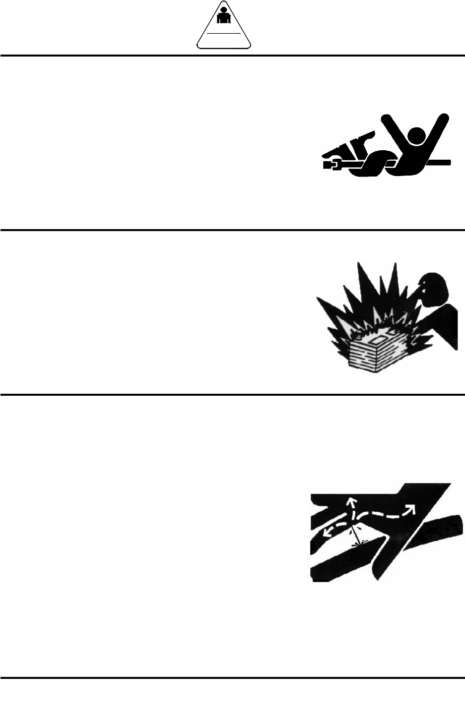
STAY CLEAR OF ROTATING DRIVELINES
Entanglement in rotating driveline can cause serious
injury or death.
Keep tractor master shield and driveline shields in place
at all times. Make sure rotating shields turn freely.
Wear close fitting clothing. Stop the engine and be sure
PTO driveline is stopped before making adjustments,
connections, or cleaning out PTO driven equipment .
PREVENT BATTERY EXPLOSIONS
Keep sparks, lighted matches, and open flame away
from the top of battery. Battery gas can explode.
Never check battery charge by placing a metal object
across the posts. Use a volt-meter or hydrometer.
Do not charge a frozen battery; it may explode. Warm
battery to 16C (60F)
AVOID HIGH-PRESSURE FLUIDS
Escaping fluid under pressure can penetrate the skin
causing serious injury or death.
Avoid the hazard relieving pressure before
disconnecting hydraulic or other lines. Tighten all
connections before applying pressure.
Search for leaks with a piece of cardboard. Protect
hands and body from high pressure fluids.
If an accident occurs, see a doctor immediately. Any
fluid injected into the skin must be surgically removed
within a few hours or gangrene may result. Doctors
unfamiliar with this type of injury should reference a
knowledgeable medical source.
SAFETY
READ BEFORE
YOU FEED
11
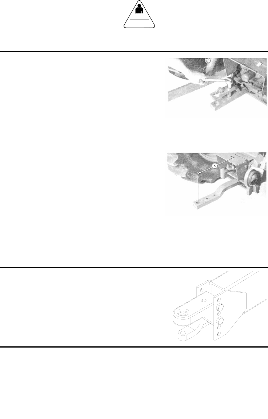
POSITIONING DRAWBAR
IMPORTANT: Drive components can be damaged
from excessive speed. Under no
circumstances should a feed mixer
equipped with 540 RPM be operated
by a tractor with 1000 RPM PTO.
Feed mixers are available with either 540 or 1000
RPM driveline. Match tractor PTO with the feed
mixer driveline.
IMPORTANT: To prevent driveline damage, adjust
tractor drawbar to recommended
setting. Disengage tractor PTO before
turning.
Remove clevis if equipped. Turn offset drawbar
down.
Adjust drawbar length:
PTO SPEED DIMENSION (A)
540 RPM 14 inches (356 mm)
1000 RPM 16 inches (406 mm)
ADJUST TRAILER HITCH CLEVIS
Mixer should be approximately level when attached
to tractor.
Adjust clevis by changing hole location on tongue.
Hitch Pin Size --- 1” x 7”
SAFETY
READ BEFORE
YOU FEED
PREPARING TRACTOR FOR TRAILER MIXER
12
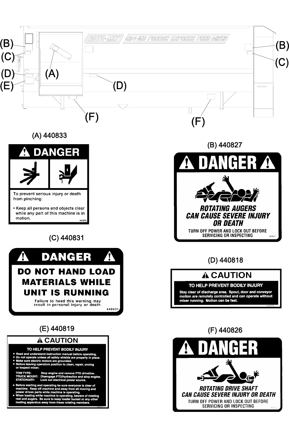
SAFETY SIGNS
13
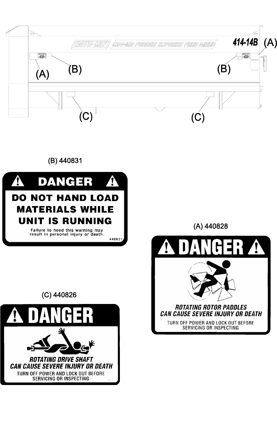
SAFETY SIGNS
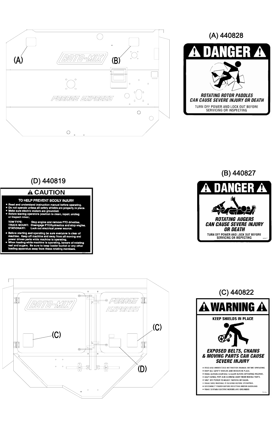
14
SAFETY SIGNS

15
SAFETY DECAL CARE
Keep safety decals and signs clean and legible at all times.
Replace safety decals and signs that are missing or have become illegible.
Replaced parts that displayed a safety sign should also display the current
sign.
Safety decals or signs are available from your dealer or the ROTO-MIX
manufacturing plant.
How to Install Safety Decals:
Be sure that the installation area is clean and dry.
Decide on the exact position before you remove the backing paper.
Remove the smallest portion of the split backing paper.
Align the decal over the specified area and carefully press the small portion
with the exposed sticky backing in place.
Slowly peel back the remaining paper and carefully smooth the remaining
portion of the decal in place.
Small air pockets can be pierced with a pin and smoothed out using the piece
of decal backing paper.
SAFETY
READ BEFORE
YOU FEED

16
REMEMBER
Your best assurance against accidents is a careful and responsible
operator. If there is any portion of this manual or function you do not
understand, contact your dealer or the ROTO-MIX plant.
BEFORE OPERATION:
Carefully study and understand this manual.
Do not wear loose-fitting clothing which may catch in moving parts.
Always wear protective clothing and substantial shoes.
Keep wheel lug nuts or bolts tightened to specified torque.
Assure that agricultural implement tires are inflated evenly.
Give the unit a visual inspection for any loose bolts, worn parts or cracked
welds, and make necessary repairs. Follow the maintenance safety
instructions included in this manual.
Be sure that there are no tools lying on or in the mixer/feeder.
Do not use the unit until you are sure that the area is clear, especially children
and animals.
Because it is possible that this mixer/feeder may be used in dry areas or the
presence of combustibles, special precautions should be taken to prevent fires
and fire fighting equipment should be readily available.
Don’t hurry the learning process or take the unit for granted. Ease into it and
become familiar with your new mixer/feeder.
Practice operation of your mixer/feeder and its attachments. Completely
familiarize yourself and other operators with its operation before using.
Securely attach to towing unit. Use a high strength, appropriately sized hitch
pin with a mechanical retainer.
Do not allow anyone to stand between the tongue or hitch and the towing
vehicle when backing up to the mixer/feeder.
SAFETY
READ BEFORE
YOU FEED

17
DURING OPERATION:
Beware of bystanders, particularly children! Always look around to make
sure that it is safe to start the engine of the towing vehicle or move the unit.
This is particularly important with higher noise levels and quiet cabs, as you
may not hear people shouting.
NO PASSENGERS ALLOWED - Do not carry passengers anywhere on, or in,
the tractor or equipment, except as required for operation.
Keep hands and clothing clear of moving parts.
Do not clean, lubricate or adjust your mixer/feeder while it is moving.
Be especially observant of the operating area and terrain - watch for holes,
rocks or other hidden hazards. Always inspect the area prior to operation.
Do not operate near the edge of drop-offs or banks.
Do not operate on steep slopes as overturn may result.
Operate up and down (not across) intermediate slopes. Avoid sudden starts
and stops.
Pick the levelest possible route when transporting across fields. Avoid the
edges of ditches or gullies and steep hillsides.
Be extra careful when working on inclines.
Periodically clear the equipment of brush, twigs or other materials to prevent
buildup of dry combustible materials.
Maneuver the tractor or towing vehicle at safe speeds.
Avoid overhead wires or other obstacles. Contact with overhead lines could
cause serious injury or death.
Avoid loose fill, rocks and holes; they can be dangerous for equipment
operation or movement. Allow for unit length when making turns.
Do not walk or work under raised components or attachments unless securely
positioned and blocked.
Keep all bystanders, pets and livestock clear of the work area.
Operate the towing vehicle from the operator’s seat only.
Never stand alongside of the unit with engine running. Never attempt to start
engine and/or operate machine while standing alongside of unit.
SAFETY
READ BEFORE
YOU FEED

18
DURING OPERATION (CONT.)
Never leave running mixer/feeder unattended.
As a precaution, always recheck the hardware on mixer/feeder following every
100 hours of operation. Correct all problems. Follow the maintenance safety
procedures.
FOLLOWING OPERATION:
Following operation, or when unhitching, stop the tractor or towing vehicle, set
the brakes, disengage the PTO and all power drives, shut off the engine and
remove the ignition keys.
Store the unit in an area away from human activity.
Do not park equipment where it will be exposed to livestock for long periods of
time. Damage and livestock injury could result.
Do not permit children to play on or around the stored unit.
Make sure parked machine is on a hard, level surface and engage all safety
devices.
Wheel chocks may be needed to prevent unit from rolling.
HIGHWAY AND TRANSPORT OPERATIONS:
Adopt safe driving practices:
Keep the brake pedals latched together at all times. Never use
independent braking with machine in tow as loss of control and/or
upset of unit can result.
Always drive at a safe speed relative to local conditions and ensure that
your speed is low enough for an emergency stop to be safe and secure.
Deep speed to a minimum.
Reduce speed prior to turns to avoid the risk of overturning.
Avoid sudden uphill turns on steep slopes.
Always keep the tractor or towing vehicle in gear to provide engine braking
when going downhill. Do not coast.
Do not drink and drive.
SAFETY
READ BEFORE
YOU FEED

19
HIGHWAY AND TRANSPORT OPERATIONS (CONT.):
Comply with state and local laws governing highway safety and movement of
farm machinery on public roads.
Use approved accessory lighting flags and necessary warning devices to
protect operators of other vehicles on the highway during daylight and
nighttime transport.
The use of flashing amber lights is acceptable in most localities. However,
some localities prohibit their use. Local laws should be checked for all
highway lighting and marking requirements.
When driving the tractor and mixer/feeder on the road or highway under 20
MPH (40 KPH) at night or during the day, use flashing amber warning lights
and a slow moving vehicle (SMV) identification emblem.
Plan your route to avoid heavy traffic.
Be a safe courteous driver. Always yield to oncoming traffic in all situations,
including narrow bridges, intersections, etc.
Be observant of bridge loading ratings. Do not cross bridges rated lower than
he gross weight at which you are operating.
Watch for obstructions overhead and to the side while transporting.
Always operate mixer/feeder in a position to provide maximum visibility at all
times. Make allowances for increased length and weight of the mixer/feeder
when making turns, stopping the unit, etc.
PERFORMING MAINTENANCE:
Good maintenance is your responsibility. Poor maintenance is an invitation to
trouble.
Make sure there is plenty of ventilation. Never operate the engine of the
towing vehicle in a closed building. The exhaust fumes may cause
asphyxiation.
Before working on the mixer/feeder, stop the towing vehicle, set the brakes,
disengage the PTO and all power drives, shut off the engine and remove the
ignition keys.
Be certain all moving parts on attachments have come to a complete stop
before attempting to perform maintenance.
Always use a safety support and block the wheels. Never use a jack to
support the machine.
SAFETY
READ BEFORE
YOU FEED

20
PERFORMING MAINTENANCE (CONT.):
Always use the proper tools or equipment for the job at hand.
Use extreme caution when making adjustments.
Never use our hands to locate hydraulic leaks on attachments. Use a small
piece of cardboard or wood. Hydraulic fluid escaping under pressure can
penetrate the skin.
When disconnecting hydraulic lines, shut off hydraulic supply and relieve all
hydraulic pressure.
Openings in the skin and minor cuts are susceptible to infection from hydraulic
fluid. If injured by escaping hydraulic fluid, see a doctor at once. Gangrene
can result. Without immediate treatment, serious infection and reactions can
occur.
Replace all shields and guards after servicing and before moving.
After servicing, be sure all tools, parts and service equipment are removed.
Do not allow grease or oil to build up on any step or platform.
Never replace hex bolts with less than grade five (5) bolts unless otherwise
specified.
Where replacement parts are necessary for periodic maintenance and
servicing, genuine factory replacement parts must be used to restore your
equipment to original specifications. ROTO-MIX will not claim responsibility for
use of unapproved parts and/or accessories and other damages as a result of
their use.
If equipment has been altered in any way from original design, ROTO-MIX does
not accept any liability for injury or warranty.
A fire extinguisher and first aid kit should be kept readily accessible while
performing maintenance on this mixer/feeder.
SAFETY
READ BEFORE
YOU FEED

21
READ THE FOLLOWING BEFORE WELDING ON THIS MIXER/FEEDER
When welding on your mixer/feeder, do not allow the current to flow through the ball
bearings or the roller chains. Ground directly to the item being welded.
Always disconnect the scale instrumentation from the weigh bars or load cells and the
power source. Be sure the current does not pass through weigh bars or load cells or
scale indicator. The alternator should always be disconnected if the mixer/feeder is not
disconnected from the towing vehicle.
CHAIN TENSION
All the single roller chain should be tightened to the point of .042” (1 mm) (dime)
clearance is reached between the coils of the 1-1/4” idler tension springs
and .068” (1.7 mm) (nickel) clearance is reached between the coils of the 1-3/4”
idler tension springs.
LOADING INSTRUCTIONS & PRECAUTIONS
A. Do not add side board extensions to the mixer.
B. Do not overload the mixer. Mixer capacity can be reached by weight or volume.
By volume, the rotor bars and wipers should always be visible at the peak of the
rotor cycle. If the rotor is completely submerged under the mix, mixing efficiency
may be reduced, spillage may occur, and damage to the mixer may result.
Maximum capacity by weight can be calculated by multiplying 28 pounds times
mixer cubic foot capacity.
C. Load molasses and/or liquid protein supplements first with mixer not running, then
add one (1) commodity ingredient before starting the mixer. For the shortest
mixing time and maximum mixing efficiency, these items should be added at the
first of the loading process.
D. When adding minute supplements or medication in non-liquid form, these
ingredients should be loaded in the middle of the loading sequence.
E. RATIONS WITH GROUND HAY:
1. Load molasses (or liquids) first with the mixer not running.
2. Load one (1) commodity ingredient and start mixer.
3. Finish loading commodities, silage, or ground hay. Loading ground hay after
mixing liquids with another commodity will prevent molasses hay balls.
NOTE: These procedures may not work on all rations. Loading sequences may
be changed to give best possible mix.
ATTENTION:
F. Never load the mixer from the right side (side opposite the discharge) with a front
end loader of payloader.

22
OPERATION:
Trailer mounted mixers can be furnished with single tractor controls or dual controls.
Dual controls are standard unless specified.
1. Single controls operate as follows: Spout goes down first - door opens
second. Door closes first - spout goes up second.
2. The disadvantage of the single control is that it does not let you adjust
the spout height without first closing the door.
ROTO-HAY PROCESSOR
The ROTO-HAY PROCESSOR is designed for processing hay into the mixer. This
eliminates the need for grinding hay, which saves the time and expense of grinding
and can save up to 18% loss from wind and handling.
THE ROTO-HAY PROCESSOR MUST BE PROPERLY USED
ALWAYS USE DRY HAY
Drain rain water out of mixer before use. 1” of rain in a 524-15 equals (72 gal) 586
lbs. of water which will increase the moisture in 1500 lbs. of dry hay (12%) to 37%
moisture or 1000 lbs. of dry hay to 45% moisture.
The ROTO-HAY PROCESSOR will handle small amounts of damp hay, but this is
done at your own risk. ROTO-MIX will not warranty bent or broken rotor tubes, bent or
broken augers, or bent hay pans caused from misuse, wet hay, foreign objects, and/or
overloading.
HAY PREPARATION:
1. SMALL BALES - (60 to 150 lbs., 2 or 3 wire) Remove twine or wire from
bales and break bales apart by pushing into a pole with a front end
loader.
2. LARGE SQUARE BALES - (3’ x 4’ x 8’ or 4’ x 4’ x 8’)
A. Position bale so you can et to end of bale with front end loader.
B. Remove twine or wrapping.
C. With front end loader, pull a 12” flake away from the bale so it can
be picked up with loader bucket - or - by adding 3 or 4 teeth (12”
long) to the top of your loader bucket, you can stab the end of the
bale and pick up a 12” flake to lay on the mixer hay pan.
3. ROUND BALES
A. Remove twine or wrapping.
B. Cut bale with a ROTO-BALE CUTTER a minimum of 5 times to part
the bale into a minimum of 12” chunks. More times may be desired
for ease of handling.
C. Break bales apart by pushing into a pole with a front end loader so
the hay can be loaded in quantities of approximately 200 lbs. at a
time.

23
LOADING INSTRUCTIONS FOR HAY PROCESSOR
Load all commodities except liquids on the discharge (auger) side with the hay pan in
the raised position. The raised hay pan does not affect the mixing action
1. If molasses and/or liquid protein is used, load on the rotor side of the mixer
first with the mixer not running.
2. Load one (1) grain or dry commodity in a minimum amount equal to the
amount of hay to be put into mixer with the mixer not running.
3. Start the mixer and run approximately one (1) minute before adding hay.
4. With the mixer running at a minimum rotor speed of 4 RPM, load prepared
hay towards the front of the hay pan on discharge side of mixer. For best
results, when loading with a tractor front end loader or payloader, each
bucket load should not exceed 200 lbs at one time. Allow time for the hay
to be processed into the mixer before loading another 200 lbs. Repeat
until desired amount of hay is processed (DO NOT OVERLOAD). Let the
mixer run until desired length of hay is reached.
5. Finish loading dry commodities.
6. Load wet feeds, such as silage, after all commodities and hay are in the
mixer.
7. If water is to be added to the ration - Do this last!
MIXER INFORMATION
The mixer trailers are equipped with recapped tires with a new tread cap.

24
LUBRICATION CHART
DISENGAGE PTO & SHUT OFF POWER BEFORE LUBRICATING THE MACHINE.
LOOSE OR FLOPPY CLOTHING SHOULD NOT BE WORN BY THE OPERATOR.
OIL BATH: Fill the oil bath with 30 weight motor oil to sight plug level.
GREASE BANK: Grease every 100 hours.
FRONT END BEARINGS: Grease every 100 hours.
INPUT BEARINGS: One (1) on input shaft beneath mixer/feeder. Grease every 100
hours.
PTO SHAFTS & U-JOINTS: Grease every 10 to 20 hours.
GEARBOX: Prior to operation, remove the uppermost plug and replace with vent plug
provided. After the first 100 hours of operation, drain the initial oil,
preferably warm. Flush the gear case with an approved non-flammable,
non-toxic solvent and refill with oil. Thereafter oil should be changed
every 2500 hours or every 12 months, whichever occurs first. Fill the
gearbox with 1-1/2 pints of either AGMA 5 EP or GL 90 lube.
SAFETY
READ BEFORE
YOU FEED
SAFETY
READ BEFORE
YOU FEED
SAFETY
READ BEFORE
YOU FEED

25
524-15 SPECIFICATIONS
Capacity (Cu. ft.) .......................................... 520
Struck level capacity (Cu. ft.) ....................... 560
Top Auger Bearing (Front) ........................... 2-3/16” 4-Bolt
Top Auger Bearing (Rear)............................ 3” 4-Bolt
Bottom Auger Bearing (Front)...................... 2-7/16” 4-Bolt
Bottom Auger Bearing (Rear) ...................... 3-1/2” 4-Bolt
Rotor Bearing (Front) ................................... 2-15/16” 4-Bolt
Rotor Bearing (Rear).................................... 4” 4-Bolt
Top Auger Sprockets ................................... 120 A 26H & 100 A 54
Bottom Auger Sprockets .............................. 120 A 48 & 120 B 13
Rotor Sprocket ............................................. 120 A 100
Jackshaft Sprockets..................................... 100 B 17H & 80 B 48 - Trk & Trl 540 PTO
100 B 15H & 80 B 48 - 1000 PTO
Drive Sprockets............................................ 80 B 25H - Trk & Trl 540 PTO
80 B 15H - Trl 1000 PTO
Top Auger Flighting...................................... 3/8” x 20”OD RH 14” Pitch
Bottom Auger Flighting ................................ 1/2” x 20”OD RH & LH Full Pitch
Tub Bottom Construction ............................. 1/4” Steel
Auger Bottom Construction.......................... 1/4” Steel
Right Side Sheet Construction..................... 7GA (3/16”) Steel
Left Side Sheet Construction ....................... 7GA (3/16”) Steel
Front End Sheet Construction...................... 1/4” Steel
Rear End Sheet Construction ...................... 1/4” Steel

26
PTO CHART
524-15
PTO GEARBOX INPUT JACKSHAFT
(% ENGINE SPEED) (RATIO) SPROCKET SPROCKET
DIESEL 80-85
AUTO 250 FT./LB MIN. 3:1 25 Tooth 17 Tooth
TRANS Engine Rotation 48 Tooth
FOR OTHER ENGINE OR TRANSMISISSION APPLICATIONS CONSULT FACTORY
1000
TRACTOR 15 Tooth 15 Tooth
DRIVE
(OPTIONAL) 48 Tooth
540
TRACTOR 25 Tooth 17 Tooth
DRIVE
(STANDARD) 48 Tooth
STATIONARY BELT RATIO
30 HP 5V-2 Groove 16” &
5V-3 Groove 9.25”
2 Belts 5V-1060
25HP 5V-2 Groove 16” &
5V-3 Groove 9.25”
2 Belts 5V-1060
NOTE: IF OPTIONAL HAY PROCESSOR IS INSTALLED A 30HP MOTOR IS REQUIRED.
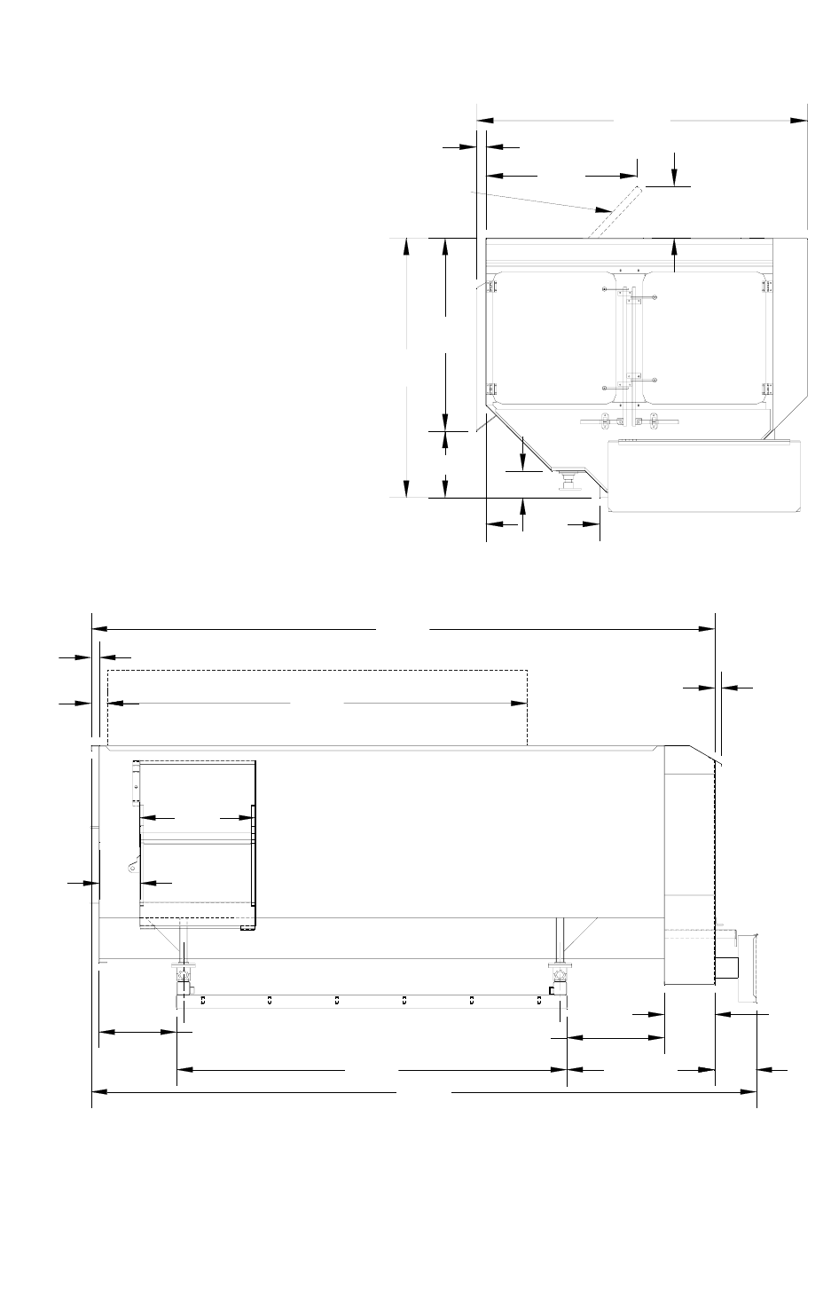
27
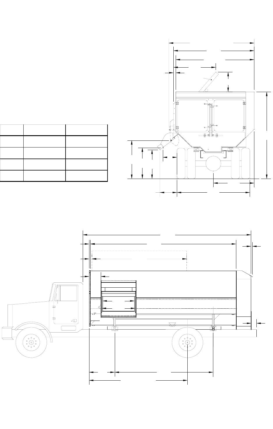
D96"
AB
108"
(SPOUT CLOSED)
106"
101 1/2"
OPTIONAL HAY
PROSESSOR
115"
56"
52"
C
52"
18"
4 1/2"
C
L
L
C
C
L
125"4 3/4"
2 1/2" 180"
215"
2"
OPTIONAL HAY PROCESSOR
8"
49" 112"
120" - 126" CA
12"
44"
42"
All Dimensions & Specifications are Approximate and Subject to Change Without Notice
524-15 TRUCK DIMENSIONS
HEIGHT DIMENSIONS BASED ON 38” TRUCK
FRAME WITH 20” SPOUT STANDARD
APPROXIMATE WEIGHT
524-15 ON TRUCK ................ 10,800 LB.
WITH HAY PROCESSOR ..... 11,550 LB.
17" SPOUT 20" SPOUT
A45-1/2" 43-1/2"
B42-1/2" 40-1/2"
C18" 20-1/2"
D22" 24-1/2"
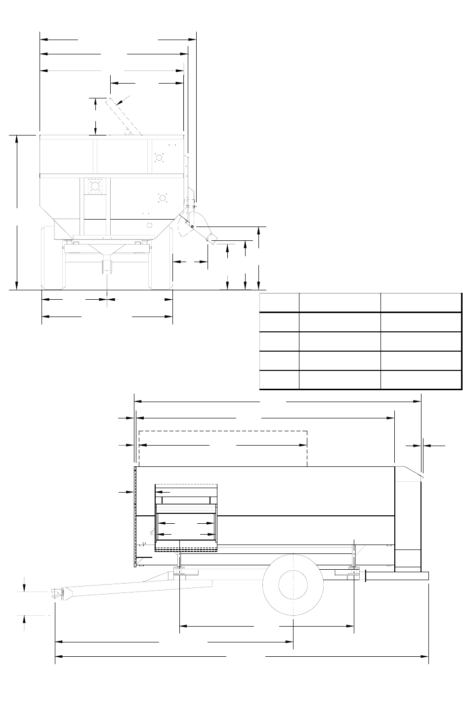
28
*B *A
48"
C
99"
110"
(SPOUT CLOSED)
106"
*107"
94" to 102"
OPTIONAL HAY
PROSESSOR
L
C
49"
18"
47" to 51"47"
SIDE OF MIXER
125"
180"
201"
4 3/4"
2 1/2"
OPTIONAL HAY PROCESSOR
2"
256 1/2"
157" - 176"
C
LC
L
17"
THRU 20"
C
L
112"
12"
44"
46 3/8"
524-15 TRAILER DIMENSIONS
HEIGHT DIMENSIONS ARE
BASED ON 44” O.D. TIRES
17” SPOUT STANDARD
APPROXIMATE WEIGHT
524-15 ON TRAILER ......... 12,500 lbs
W/HAY PROCESSOR........ 13,250 lbs
*INCREASE DIMENSIONS BY 4”
WHEN OPTIONAL RISER
BLOCKS ARE INSTALLED.
All Dimensions & Specifications are Approximate and Subject to Change Without Notice
17" SPOUT 20" SPOUT
A37-1/2" 35-1/2"
B34-1/2" 32-1/2"
C16" - 20" 18-1/2" - 22-1/2"
D20" - 24" 22-1/2" - 26-1/2"
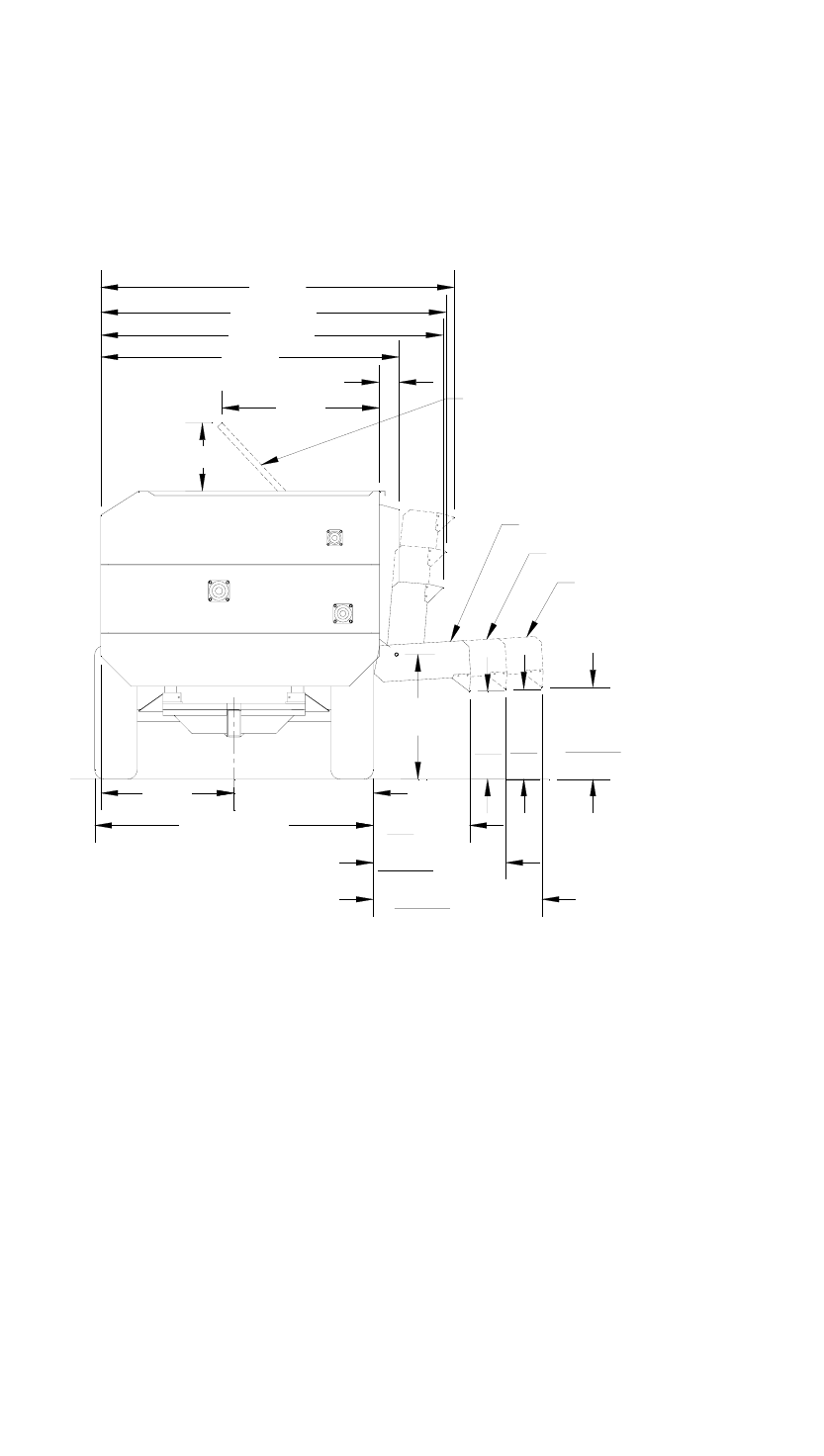
29
C
L
36" 44"
48"
40"
54"
35 1/2"
59 1/2"
33" - 35"
OPTIONAL HAY
PROCESSOR
18"
126"
124 1/4"
122 1/2"
106"
49"
7"
44"
94" to 102"
47" to 51"
43 1/4" - 45 1/4"
53 1/2" - 55 1/2"
48" CONVEYOR
36" CONVEYOR
24" CONVEYOR
524-15 TRAILER DIMENSIONS
(WITH CONVEYOR)
All Dimensions & Specifications are Approximate and Subject to Change Without Notice
NOTE: UNDERLINED DIMENSIONS ARE WITH
CONVEYOR SET AT ITS MAXIMUM
OPERATING ANGLE OF 30 DEGREES
30
106"
OPTIONAL HAY
PROCESSOR
4 1/2"
18"
52"
83"
59 1/2"
23 1/2"
21"
10 1/2"
524-15 STATIONARY DIMENSIONS
125"4 3/4"
2 1/2"
180"
2"
OPTIONAL HAY PROCESSOR
215"
12"
32"
30"
128" 38 1/2" 16"
16 1/2"
22"
APPROXIMATE WEIGHT, LESS MOTOR
524-15 STATIONARY.................... 10,500 LB.
WITH HAY PROCESSOR.............. 11,250 LB.
All Dimensions & Specifications are Approximate and Subject to Change Without Notice
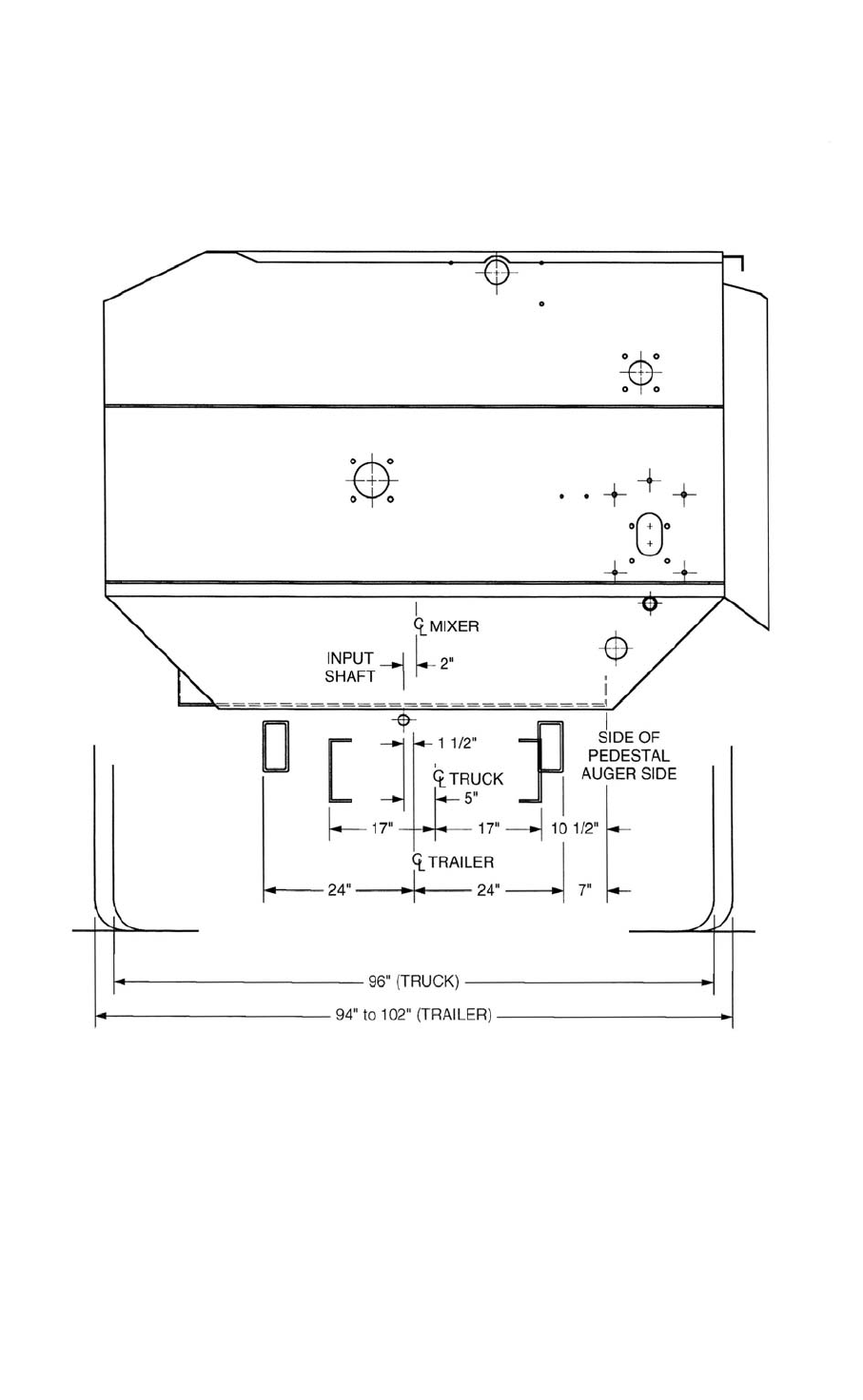
31
524-15 MOUNTING DIMENSIONS
All Dimensions & Specifications are Approximate and Subject to Change Without Notice
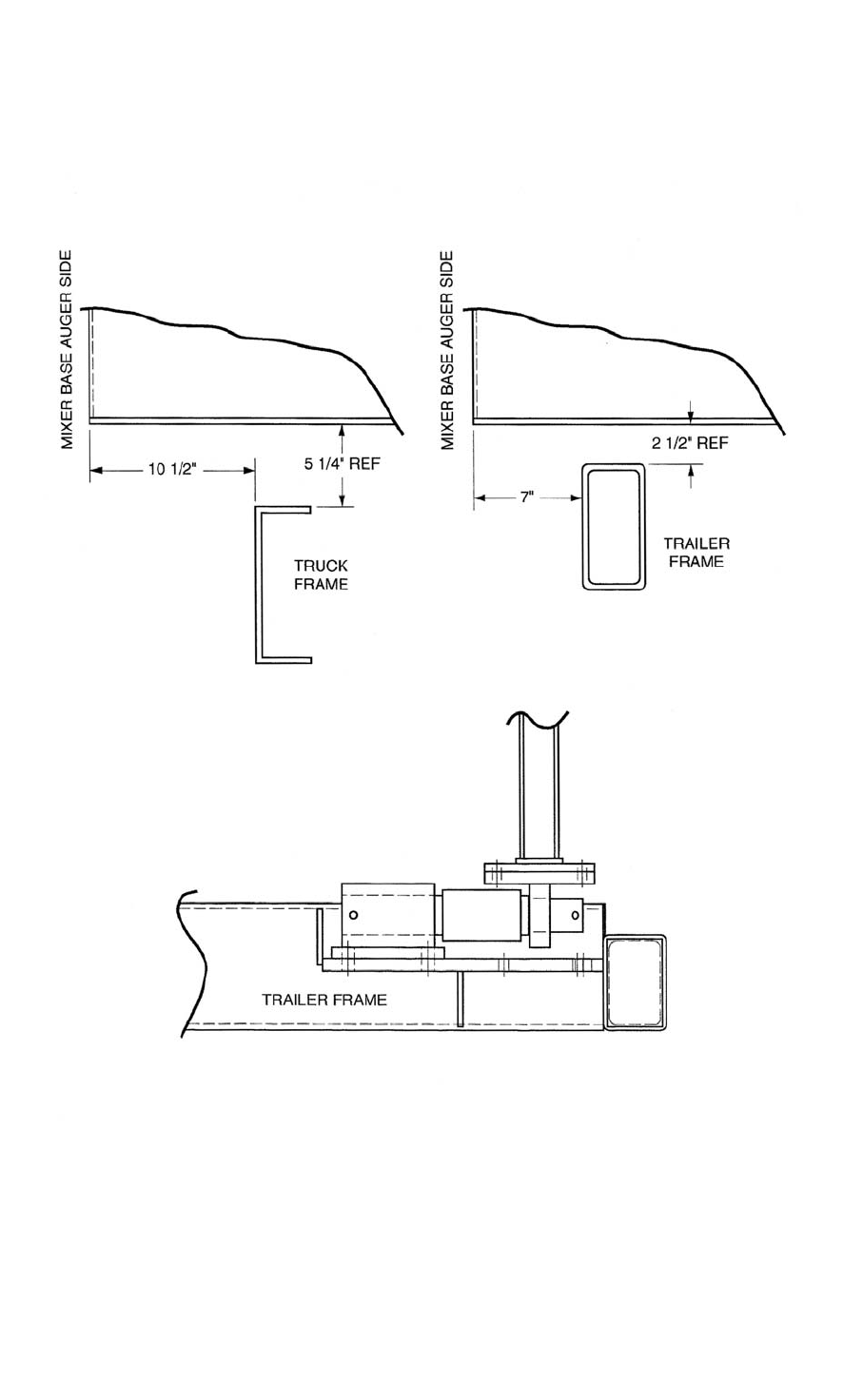
32
524-15 MOUNTING DIMENSIONS
All Dimensions & Specifications are Approximate and Subject to Change Without Notice

33
PARTS PAGES
TABLE OF CONTENTS
PAGE NO.
WIRING SCHEMATIC FOR STRAIGHT DOOR ............................................................ 34
JOYSTICK ASSEMBLY ....................................................................................................... 35
MV5 DOUBLE HYDRAULIC VALVE ASSEMBLY ........................................................ 36
12V DOUBLE HYDRAULIC VALVE ASSEMBLY .......................................................... 37
HYDRAILIC PUMP, TRUCK .............................................................................................. 38
OIL RESERVOIR ASSEMBLY ........................................................................................... 39
HYDRAULIC SCHEMATIC FOR STRAIGHT DOOR.................................................... 40
STATIONARY HYDRAULIC ASSEMBLY ....................................................................... 41
DISCHARGE DOOR ASSEMBLY ...................................................................................... 42
DISCHARGE DOOR HAND WHEEL ASSEMBLY ......................................................... 43
17” SPOUT ASSEMBLY ....................................................................................................... 44
20” SPOUT ASSEMBLY ....................................................................................................... 45
SPOUT MAGNET ASSEMBLY ........................................................................................... 46
SPOUT RUBBER.................................................................................................................... 47
CHAIN CONVEYOR ASSEMBLY....................................................................................48-49
CHAIN CONVEYOR HYDRAULIC ASSEMBLY ............................................................ 50
CONVEYOR HYDRAULIC ASSEMBLY (2 CYLINDER)............................................... 51
SCALE INDICATOR ASSEMBLY...................................................................................... 52
OIL BATH DOOR ASSEMBLY........................................................................................... 53
LUBRICATION ASSEMBLY (OIL BATH)........................................................................ 54
STAGGERED ROTOR ASSEMBLY................................................................................... 55
3 ARM ROTOR ASSEMBLY ............................................................................................... 56
5 ARM ROTOR ASSEMBLY ............................................................................................... 57
TOP & BOTTOM AUGER ASSEMBLY............................................................................. 58
FRONT END BEARING ASSEMBLY ................................................................................ 59
DRIVE ASSEMBLY.............................................................................................................60-61
STATIONARY DRIVE ASSEMBLY .................................................................................62-63
DRIVE LINE GEARBOX ASSEMBLY............................................................................... 64
TRUCK DRIVELINE ASSEMBLY ..................................................................................... 65
TRUCK DRIVESHAFT ASSEMBLY.................................................................................. 66
TRAILER DRIVELINE ASSEMBLY.................................................................................. 67
TRAILER DRIVESHAFT ASSEMBLY .............................................................................. 68
TRAILER LOADCELL SCALE ASSEMBLY.................................................................... 69
TRAILER WEIGH BAR ASSEMBLY ................................................................................ 70
TRUCK LOADCELL SCALE FRAME ASSEMBLY........................................................ 71
TRUCK WEIGH BAR SCALE FRAME ASSEMBLY ...................................................... 72
STATIONARY LOAD CELL SCALE FRAME ASSEMBLY .......................................... 73
TRAILER ASSEMBLY ......................................................................................................... 74
HUB & SPINDLE ASSEMBLY ............................................................................................ 75
ROTO-HAY PROCESSOR ASSEMBLY (HYDRAULIC OPTION) ............................... 76
ROTO-HAY PROCESSOR ASSEMBLY ............................................................................ 77
ROTO-HAY PROCESSOR ASSEMBLY (CABLE OPTION).......................................... 78
BOTTOM AUGER FLOAT ASSEMBLY ........................................................................... 79
FENDERS & MUD FLAPS ................................................................................................... 80
34
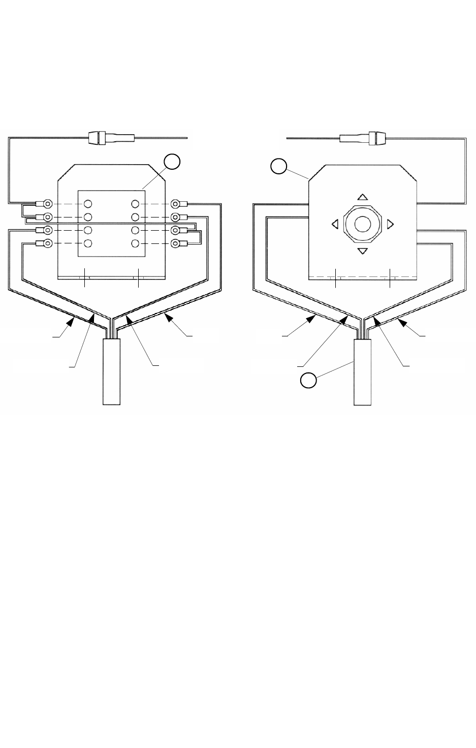
REF. NO PART NO. DESCRIPTION QTY.
1
A 780080 PUSH BUTTON SWITCH PANEL
B 780081 JOYSTICK PANEL ........................................................... 1
2 781055 TRUCK TO MIXER WIRE ASSEMBLY ............................ 1
3 780123 HYDRAULIC CONTROL VALVE...................................... 1
WIRING SCHEMATIC FOR STRAIGHT DOOR
3
1
2
YELLOW
RED
YELLOW
BROWN
GREEN
BROWN
RED
GREEN
35
JOYSTICK ASSEMBLY
BOTTOM TOP
TO 12 VOLT
BROWN BROWN
RED
GREEN
YELLOW GREEN
RED
YELLOW
REF. NO PART NO. DESCRIPTION QTY.
1 781056 SWITCH WIRE ASSEMBLY ................................................... 1
2 185575 JOYSTICK BRACKET ............................................................. 1
3 357705 JOYSTICK SWITCH................................................................. 1
2
3
1
36
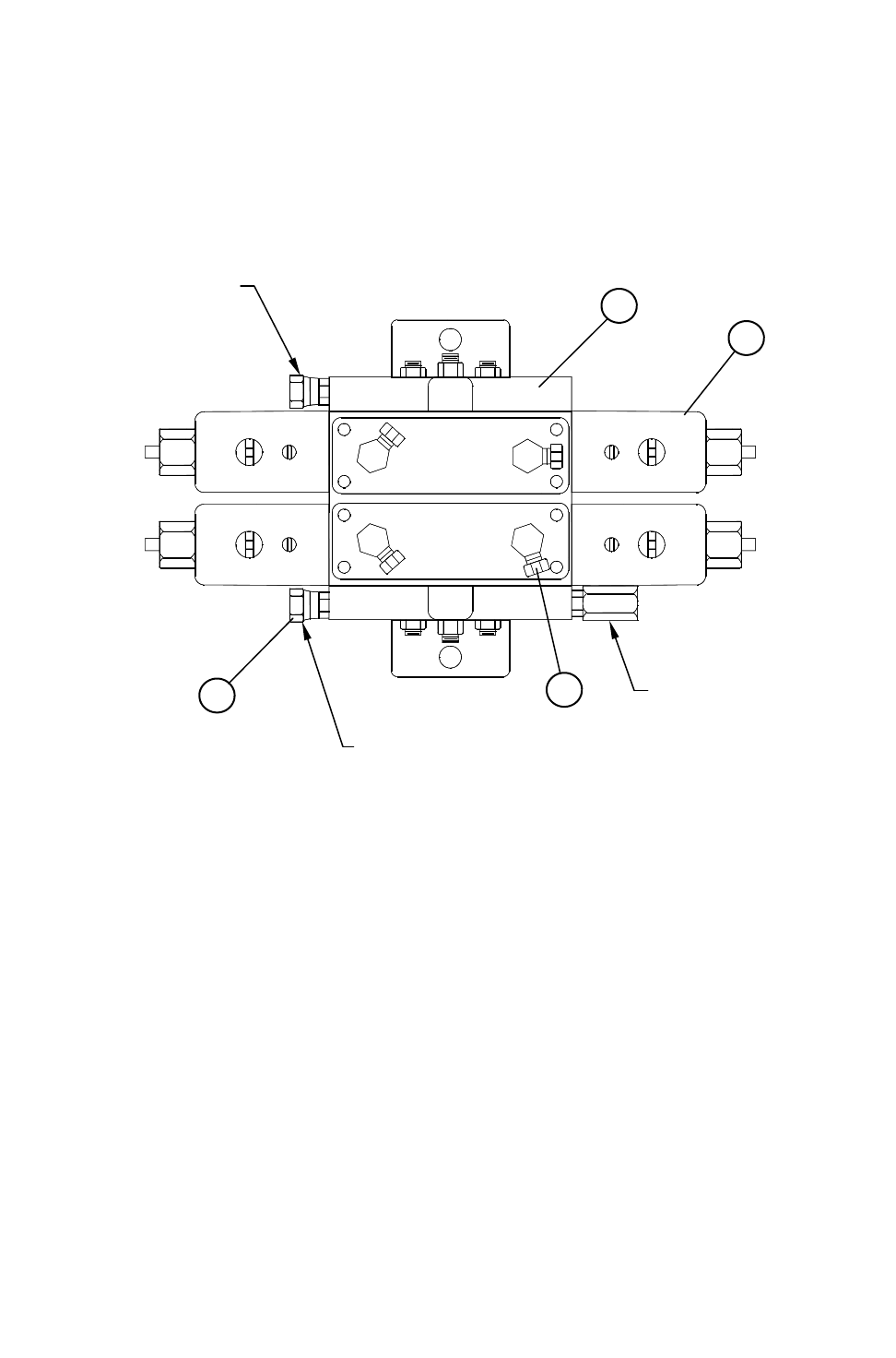
MV5 DOUBLE HYDRAULIC ASSEMBLY
(780123 OLD STYLE)
REF. NO PART NO. DESCRIPTION QTY.
1 362209 HYDRAULIC VALVE 12V DOUBLE ................................. 1
1A 362206 12V SING MV5 HYD VLV MVSR 1500-10-50-12-TD....... 2
2 368030 FITTING, 9/16”MOR x 3/8” FPSW 90° ............................. 4
3 368115 FITTING, 9/16” MOR x 3/8” FPSW STRT ........................ 2
1A
1
2
3
OUTLET
INLET
BUILT IN PRESSURE
RELIEF PRESET TO
1500 PSI
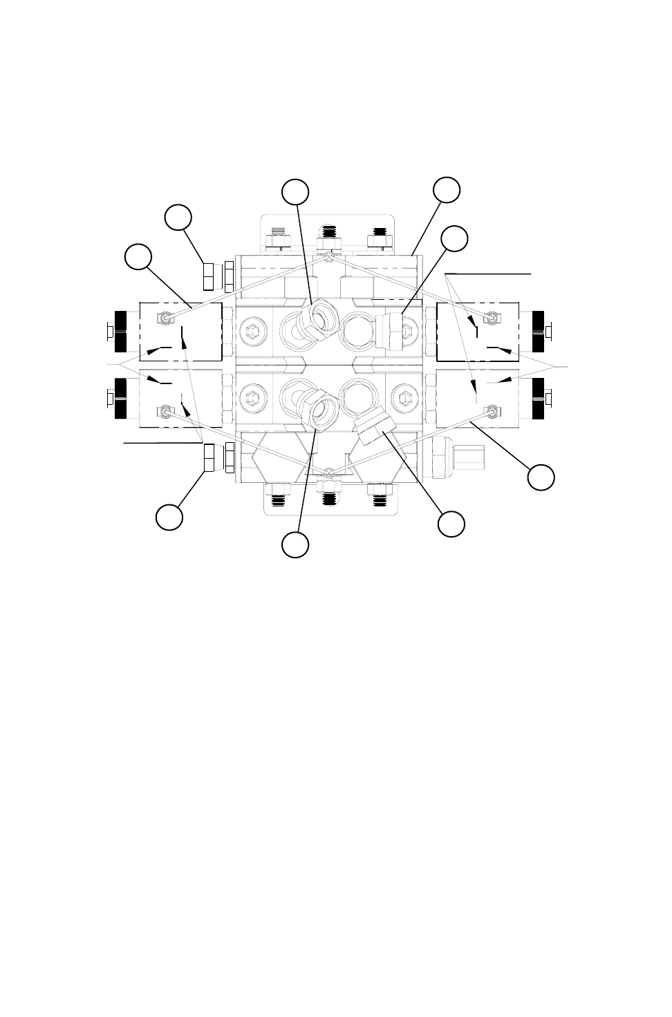
37
TO JOYSTICK
DO NOT USE
THIS POLE
TO JOYSTICK
DO NOT USE
THIS POLE
1
2
2
3
3
4
4
5
5
REF. NO PART NO. DESCRIPTION QTY.
1 362209 HYDRAULIC VALVE 12V DOUBLE..................................1
2 368115 FITTING, 9/16” MOR x 3/8” FPS.......................................2
3 368024 FITTING, 45° SWIVEL 9/16” MOR x 3/8” FPS..................2
4 368030 FITTING, 90° SWIVEL 9/16” MOR x 3/8” FPS..................2
5 781057 SOLENOID GROUND WIRE, 12 VOLT ...........................2
12V DOUBLE HYDRAULIC ASSEMBLY
(780123 NEW STYLE)

38
REF. NO PART NO. DESCRIPTION QTY.
1 336008 BUSHING, SH1/2” QD...................................................... 1
2 324040 SHEAVE, 1B 4.0” V-BELT................................................ 1
3 189053 HYDRAULIC PUMP BRACKET........................................ 1
4 362017 HYDRAULIC PUMP (D17AA2A) ...................................... 1
5 368050 FITTING, 7/8” MOR x 3/4” FPSW 90° .............................. 1
6 368512 FITTING, 3/4” MP x 3/4” PUSH LOCK BARB................... 1
7 368040 FITTING, 3/4” MOR x 3/8” FPSW 90° .............................. 1
HYDRAULIC PUMP, TRUCK (780064)
2
1
3
4
5
6
7
39
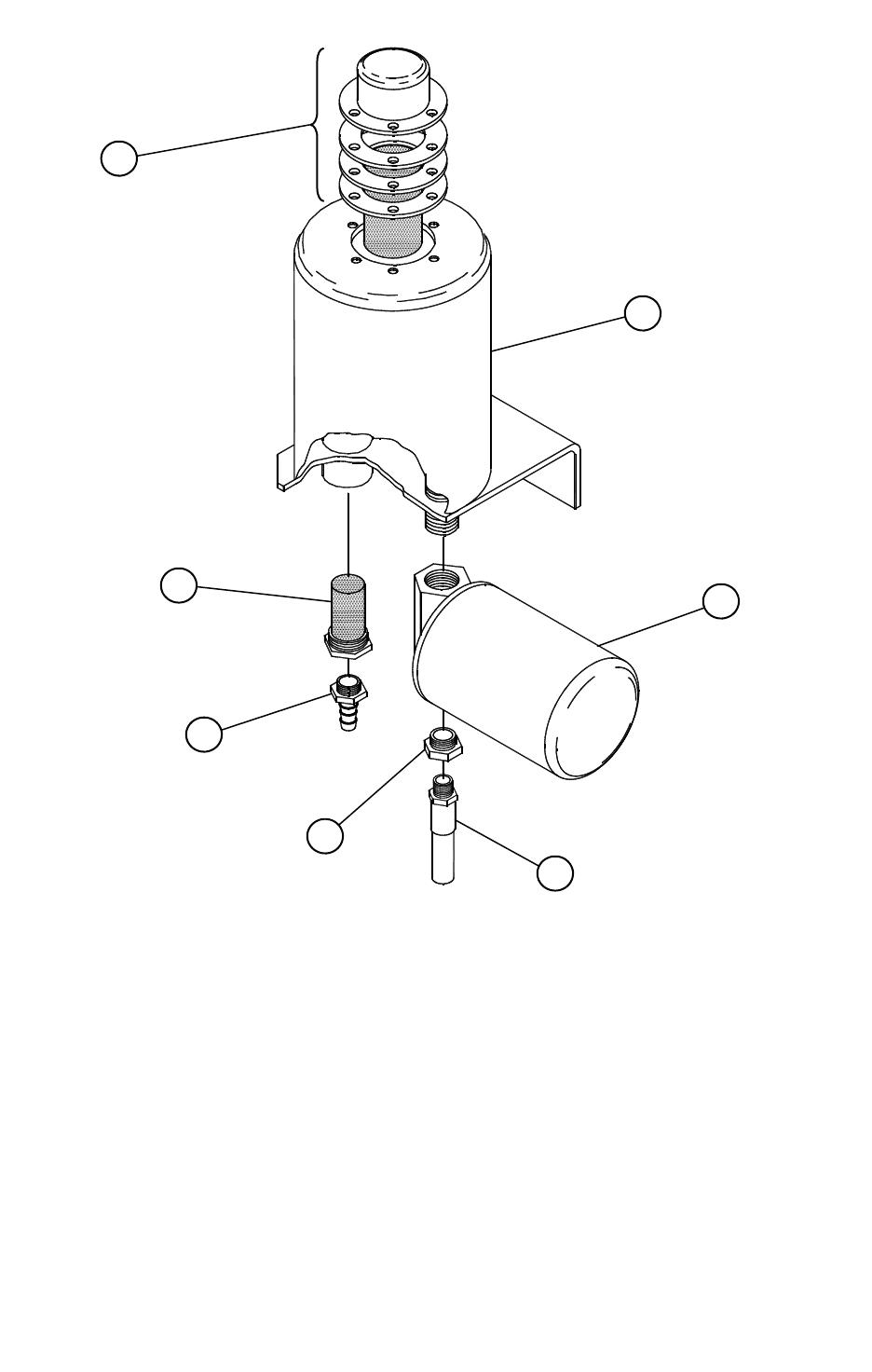
OIL RESERVOIR ASSEMBLY (780205)
REF. NO PART NO. DESCRIPTION QTY.
1 362550 FILLER CAP......................................................................1
2 870477 OIL RESERVOIR WELDMENT.........................................1
3 352400 OIL FILTER ASSEMBLY...................................................1
A 362403 FILTER HEAD
B 352440 FILTER ELEMENT
4 362504 SUCTION SCREEN ..........................................................1
5 368512 FITTING, 3/4” MP x 3/4” PUSH LOCK BARB ...................1
6 368665 FITTING, 3/4” x 3/8” REDUCER .......................................1
7 781059 HYD HOSE ASSEMBLY, 3/8” x 20” x 3/8” ENDS.............1
1
2
3
7
6
5
4
40
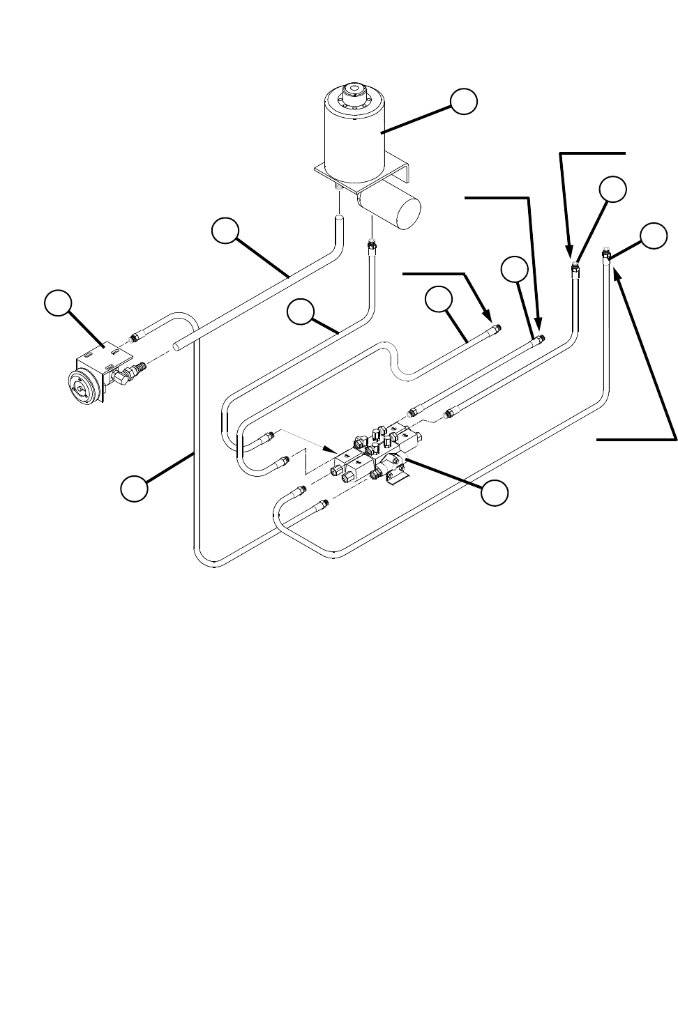
HYDRAULIC SCHEMATIC FOR STRAIGHT DOOR
NOTE A: CONNECT TO SPOUT CYLINDER BASE
NOTE B: CONNECT TO SPOUT CYLINDER ROD END
NOTE C: CONNECT TO DOOR CYLINDER BASE
NOTE D: CONNECT TO DOOR CYLINDER ROD END
REF. NO PART NO. DESCRIPTION QTY.
1 780064 HYDRAULIC PUMP ASSEMBLY ............................................. 1
2 780205 RESERVOIR ASSEMBLY ........................................................ 1
3 780123 HYDRAULIC VALVE ASSEMBLY ............................................ 1
4 781059 HYD. HOSE ASSY. 3/8” x 20” w/3/8” MP ENDS ...................... 1
5 184291 HYD. HOSE ASSY. 3/4” x 144” (SUCTION LINE).................... 1
6 781073 HYD. HOSE ASSY. 3/8” x 144” w/3/8” MP ENDS .................... 1
7 781066 HYD. HOSE ASSY. w/3/8” MP & 1/4” MP ENDS ..................... 1
8 781069 HYD. HOSE ASSY. w/3/8” MP & 1/4” MP ENDS ..................... 1
9 781061 HYD. HOSE ASSY. w/3/8” MP ENDS ...................................... 1
10 781098 HYD. HOSE ASSY. w/3/8” MP ENDS ...................................... 1
1
9
10
2
5
7
8
4
3
6
NOTE (C)
NOTE (A)
NOTE (B)
NOTE (D)
41
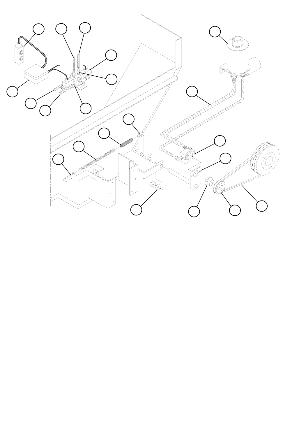
REF. NO PART NO. DESCRIPTION QTY.
1 781004 HYDRAULIC VALVE ASSEMBLY............................................ 1
A 352205 SINGLE HYDRAULIC VALVE, 120V ....................................... 1
B 368030 FITTING, 9/16” MOR x 3/8” FPSW 90° .................................... 2
C 368115 FITTING, 9/16” MOR x 3/8” FPSW STRT ................................ 2
D 357700 PENDANT SWITCH WH-4052................................................. 1
E 453717 WEATHER PROOF BOX ......................................................... 1
2 781113 STATIONARY HYDRAULIC PUMP ASSEMBLY..................... 1
3 872138 PUMP SWING ARM WELDMENT ........................................... 1
4 781005 OIL RESERVOIR ASSEMBLY ................................................. 1
5 410852 EYEBOLT, 3/8” X 8” ................................................................. 1
6 185488 2/0 PASSING LINK CHAIN x 18” ............................................. 1
7 410008 PULL SPRING, 1-1/4” x 5-1/4” ................................................. 1
8 872136 PUMP LEVER ARM WELDMENT............................................ 1
9 412416 1” SET COLLAR....................................................................... 2
10 324040 BELT SHEAVE, 1B x 4.0” SH .................................................. 1
11 336008 BUSHING, SH 1/2” QD ............................................................ 1
12 325060 V-BELT, B60 ............................................................................ 1
13 189088 SUCTION HOSE, 3/4” x 94”..................................................... 1
14 781075 HYD HOSE ASSEMBLY, 3/8” x 180” x 3/8” MP ENDS............ 1
15 781077 HYD HOSE ASSEMBLY, 3/8” x 192” x 3/8” MP ENDS............ 1
16 781099 HYD HOSE ASSEMBLY, 3/8” x 120” x 3/8” MP ENDS............ 2
STATIONARY HYDRAULIC ASSEMBLY
1D
1E
1A
15
14
1B
1C
16
16
4
13
12
3
2
10
11
9
8
7
6
5
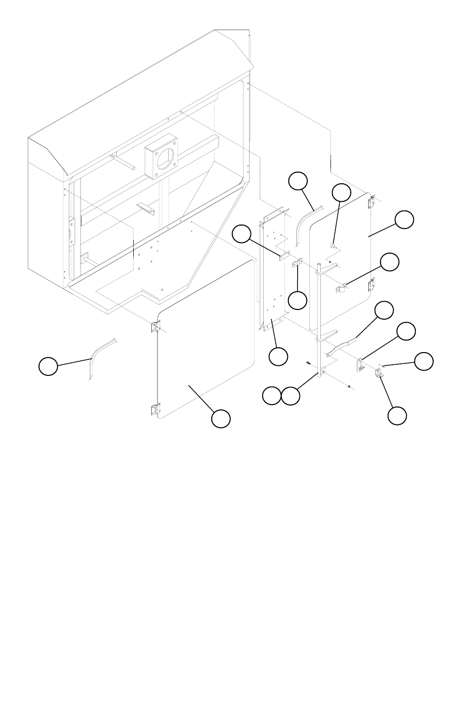
42
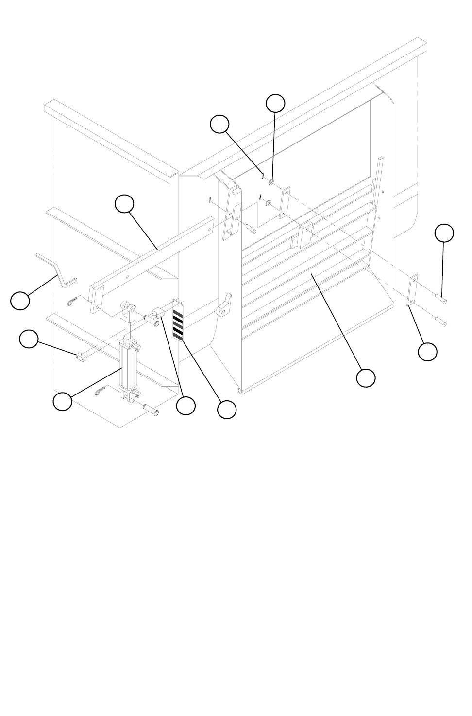
524-15 DISCHARGE DOOR ASSEMBLY
REF. NO PART NO. DESCRIPTION QTY.
1 850140 DISCHARGE DOOR WELDMENT................................... 1
2 850138 DOOR LEVER ARM WELDMENT ................................... 1
3 150049 DOOR ARM...................................................................... 2
4 404351 CLEVIS PIN 3/4” X 2-1/2”................................................. 3
5 404003 COTTER PIN 5/32” X 1 1/4” ............................................. 3
6 402512 FLAT WASHER 3/4” SAE................................................. 3
7 184267 DOOR CYLINDER MARKER CLAMP.............................. 1
8 780109 HYDRAULIC CYLINDER 2” X 8” (WITH FITTINGS)........ 1
A 364055 HYDRAULIC CYLINDER 2” X 8” (CYLINDER ONLY) ..... 1
B 364954 HYDRAULIC CYLINDER ROD 2” X 8” X 1 1/16” ............. 1
C 364400 HYDRAULIC CYLINDER 2” REPAIR KIT ........................ 1
9 184259 DOOR CYLINDER MARKER PLATE (TRUCK)............... 1
10 150385 DOOR MARKER BAR (TRAILER) ................................... 1
1
3
4
6
5
10
7
7
8 9
2
43
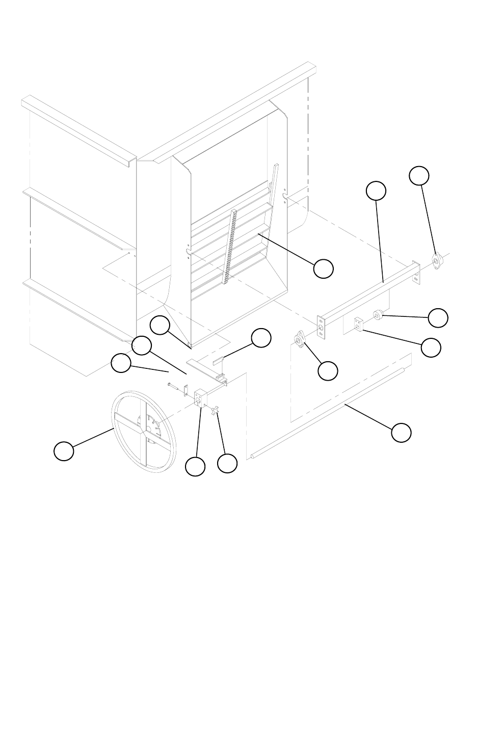
524-15 HAND WHEEL ASSEMBLY
REF. NO PART NO. DESCRIPTION QTY.
1 850079 HAND WHEEL FRAME WELDMENT................................... 1
2 850145 524 STATIONARY DOOR WELDMENT ............................... 1
3 872030 HAND WHEEL WELDMENT.................................................. 1
4 872349 BEARING BRAKE MOUNT WELDMENT ............................ 1
5 189105 BEARING BRAKE BLOCK UHMW ....................................... 1
6 189106 HAND KNOB BOLT SUPPORT .............................................. 1
7 407047 CARRIAGE BOLT 3/8”-16 X 3” .............................................. 1
8 410305 HAND KNOB ............................................................................ 1
9 189112 BRAKE ARM ............................................................................ 1
10 150387 HAND WHEEL SHAFT............................................................ 1
11 340216 FLANGE BEARING VCJT 1” 2-BOLT ................................... 2
12 150244 HAND WHEEL BEARING BLOCK UHMW. ......................... 1
13 185114 GEAR S1020 X 1” BORE.......................................................... 1
11
13
12
2
1
11
10
8
5
6 9
4
7
3
44
#750044 ..............................17” SPOUT ASSY WITH MAGNET
#750045 ..............................17” SPOUT ASSY NO MAGNET
6
2
4
5
8
5A
5B
1B 1A
3
7
REF. NO PART NO. DESCRIPTION QTY.
1A 850106 17” SPOUT WELDMENT WITH MAGNET ............................... 1
1B 850107 17” SPOUT WELDMENT NO MAGNET................................... 1
2 150383 SPOUT PIVOT TUBE ............................................................... 1
3 183152 SPOUT BACK-UP ANGLE ....................................................... 1
4 850050 SPOUT CYLINDER TOP BRACKET WELDMENT .................. 1
5 750019 SPOUT CYLINDER ASSEMBLY 1-1/2” x 8” ............................ 1
5A 400712 HEX JAM NUT 3/4”-16 ............................................................. 1
5B 850053 SPOUT CYLINDER LUG..........................................................1
6 400205 HEX NUT 5/16”-18................................................................... 10
7 402005 SPLIT LOCKWASHER 5/16” ................................................... 10
8 407021 CARRIAGE BOLT 5/16”-18 x 1” .............................................. 10
17” SPOUT ASSEMBLY
45
REF. NO PART NO. DESCRIPTION QTY.
1A 850093 20” SPOUT WELDMENT WITH MAGNET............................... 1
1B 850094 20” SPOUT WELDMENT NO MAGNET .................................. 1
2 150383 SPOUT PIVOT TUBE............................................................... 1
3 183152 SPOUT BACK-UP ANGLE....................................................... 1
4 850050 SPOUT CYLINDER TOP BRACKET WELDMENT.................. 1
5 750019 SPOUT CYLINDER ASSEMBLY 1-1/2” x 8” ............................ 1
5A 400712 HEX JAM NUT 3/4”-16 ............................................................. 1
5B 850053 SPOUT CYLINDER LUG ......................................................... 1
6 400205 HEX NUT 5/16”-18 .................................................................. 10
7 402005 SPLIT LOCKWASHER 5/16”................................................... 10
8 407021 CARRIAGE BOLT 5/16”-18 x 1”.............................................. 10
20” SPOUT ASSEMBLY
#750054 ..............................20” SPOUT ASSY WITH MAGNET
#750055 ..............................20” SPOUT ASSY NO MAGNET
6
2
4
5
8
5A
5B
1B 1A
3
7
46
REF. NO PART NO. DESCRIPTION QTY.
1A 850106 17” SPOUT WELDMENT.......................................................... 1
1B 850093 20” SPOUT WELDMENT.......................................................... 1
2 150299 SPOUT MAGNET GUARD ....................................................... 1
3 357005 ARCO PLATE MAGNET AM 2200 ........................................... 2
4 400205 HEX NUT, 5/16”-18.................................................................. 20
5 402005 LOCKWASHER, 5/16” .............................................................20
6 402405 FLAT WASHER USS, 5/16”...................................................... 4
7 407021 CARRIAGE BOLT, 5/16”-18 x 1” ............................................. 18
8 407022 CARRIAGE BOLT, 5/16”-18 x 1-1/4” ........................................2
SPOUT MAGNET ASSEMBLY
6
5 8
3
2
1
7
4
4
5
47
REF. NO PART NO. DESCRIPTION QTY.
1
A 150384 SPOUT RUBBER (17” SPOUT) ............................................... 1
B 150403 SPOUT RUBBER (20” SPOUT) ............................................... 1
2 150150 SPOUT RUBBER END PLATE ................................................ 2
3 183152 SPOUT BACK-UP ANGLE....................................................... 1
SPOUT RUBBER
3
1
2
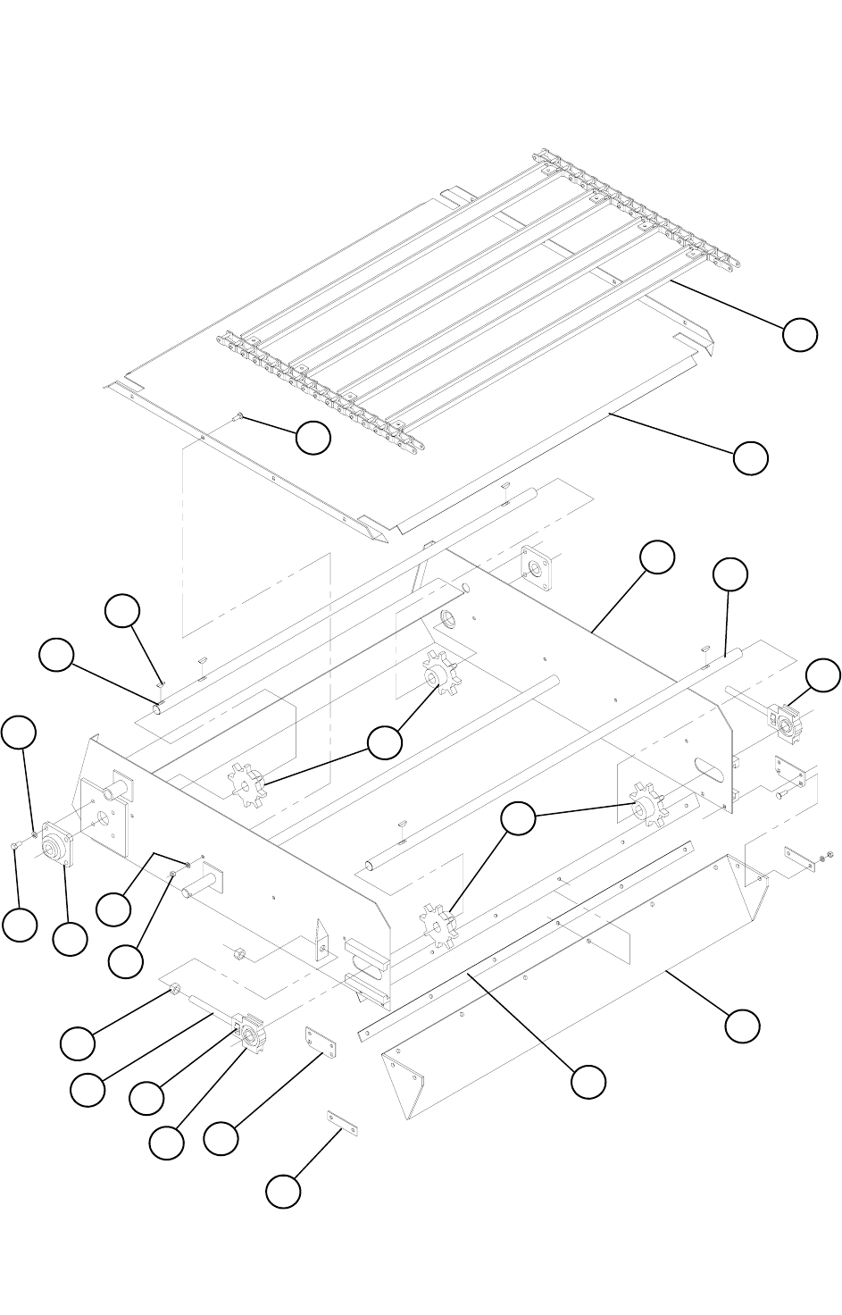
48
CHAIN CONVEYOR ASSEMBLY
18
12
9
3
13
1
10
2
5
1
11
6 4
8
7
20
17
15
16
14
11 21
19

49
CHAIN CONVEYOR ASSEMBLY
REF. NO PART NO. DESCRIPTION QTY.
1 160025 8 TOOTH #55 SPROCKET x 1”ID ....................................4
2 188427 48”W CONVEYOR DRIVE SHAFT ...................................1
3 188428 48”W CONVEYOR IDLER SHAFT....................................1
4 340316 RCJC 1” 4-BOLT FLANGE BEARING ..............................2
5 402006 SPLIT LOCKWASHER, 3/8” .............................................8
6 405652 HHCS, 3/8”-16 x 3/4”.........................................................8
7 400205 HEX NUT, 5/16”-18 ..........................................................20
8 402005 SPLIT LOCKWASHER, 5/16” .........................................20
9 407021 CARRIAGE BOLT, 5/16”-18 x 1”......................................20
10 409916 WOODRUFF KEY, 1/4” x 1”..............................................4
11 188390 CONVEYOR TAKE-UP BOLT...........................................2
12 874126 24”L x 48”W CONVEYOR PAN WELDMENT
874004 36”L x 48”W CONVEYOR PAN WELDMENT
874122 48”L x 48W CONVEYOR PAN WELDMENT ....................1
13 874128 24”L x 48”W CONVEYOR WELDMENT
874136 36”L x 48”W CONVEYOR WELDMENT
874124 48”L x 48”W CONVEYOR WELDMENT ...........................1
14 188304 CONVEYOR SPOUT RUBBER BAR - 4” .........................2
15 188384 CONVEYOR SPOUT RUBBER BAR - 45-3/4” .................1
16 188432 48”W CONVEYOR SPOUT RUBBER...............................1
17 188418 CONVEYOR SPOUT RUBBER SIDE BAR ......................2
18 874127 24”L x 48”W CONV. C55 CHAIN WELDMENT
874154 36”L x 48”W CONV. C55 CHAIN WELDMENT
874153 48”L x 48”W CONV. C55 CHAIN WELDMENT.................1
19 341323 TAKE-UP BEARING, 1” ....................................................2
20 400210 HEX NUT, 5/8”-11 .............................................................6
21 400810 UNILOCK, 5/8”-11.............................................................2
22 760000 TAKE-UP BEARING ASSY (INCLUDES 11, 19 & 21)......2
#781414 .............. 24”L x 48”W CONVEYOR ASSEMBLY
#781464 .............. 36”L x 48”W CONVEYOR ASSEMBLY
#781465 .............. 48”L x 48”W CONVEYOR ASSEMBLY
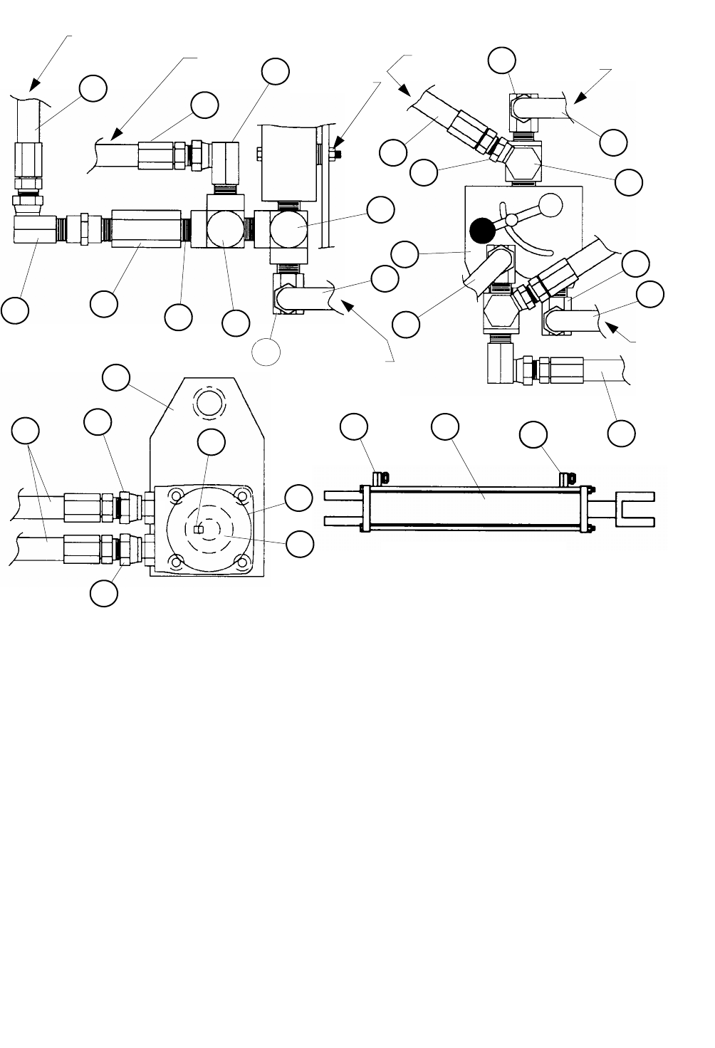
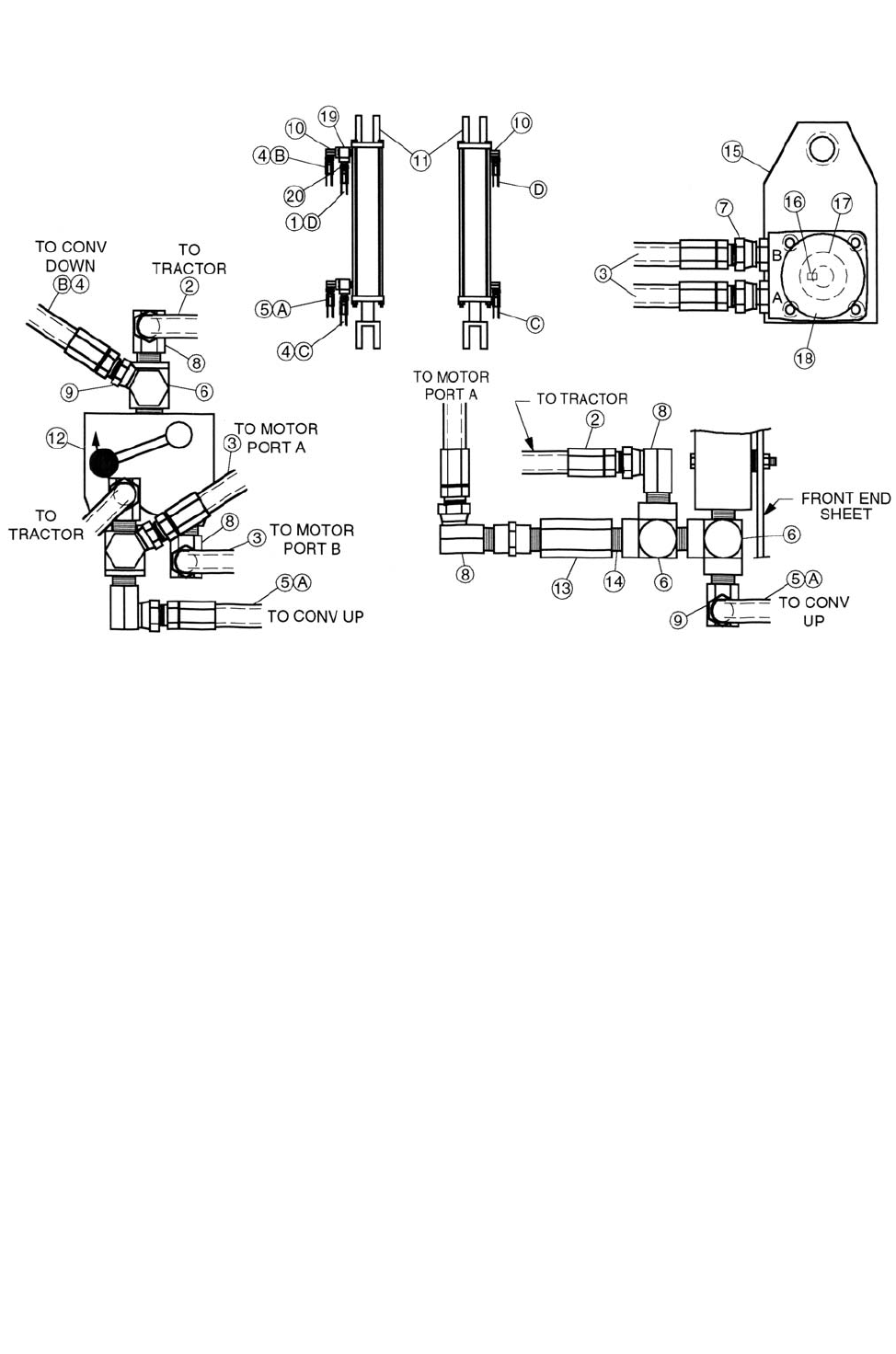
50
TO MOTOR
PORT B
REF. NO PART NO. DESCRIPTION QTY.
1 874071 CONVEYOR MOTOR PLATE WELDMENT ......................... 1
2 781329 HYD. HOSE ASSY 3/8” X 125” (3/8”MP ENDS) ...................1
3 781328 HYD. HOSE ASSY 1/2” X 128” (1/2”MP ENDS) ...................2
4 781327 HYD. HOSE ASSY 1/2” X 56” (1/2”MP ENDS) .....................2
5 781236 HYD. HOSE ASSY 3/8” X 112” (3/8”MP ENDS) ...................1
6 409916 WOODRUFF KEY 1/4” X 1”....................................................1
7 368608 FITTING, 1/2”MP X 1/2”FP X 1/2”FP TEE ............................. 3
8 368118 FITTING, 7/8”MOR X 1/2”FPSW ............................................2
9 368031 FITTING, 1/2”MP X 1/2”FPSW 90° .........................................4
10 368028 FITTING, 1/2” X 3/8”FPSW .....................................................2
11 368007 FITTING, 3/8”MP X 3/8”FPSW 90° .109” ORFICE ................ 2
12 364060 HYDRAULLIC CYLINDER 2” X 16” .....................................1
13 362283 HYDRAULIC FLOW CONTROL VALVE..............................1
14 362240 BALL CHECK VALVE 1/2”FP X 1/2”FP ................................1
15 360009 HYDRAULIC MOTOR, 9.7 CI ................................................. 1
16 332654 KEY, 1”ID X 2”OD X 3”LTB CPLG W/1/4” ...........................1
17 310805 CLOSE NIPPLE, 1/2” ................................................................1
CONVEYOR CYLINDER
11
A
B
10
TO
MOTOR TO
TRACTOR FRONT
END SHEET
TO CONV UP
TO CONV
DOWN
TO
TRACTOR
9
3
5
10
13
3
2
7
9
3
4
7
17
14
9
4 8
6
1
11 12 11 2
15
16
7
9
4
8
CHAIN CONVEYOR HYDRAULIC ASSEMBLY
51
REF. NO PART NO. DESCRIPTION QTY.
1 781355 HYD HOSE ASSY 3/8” x 105” (3/8” MP ENDS)............... 1
2 781328 HYD. HOSE ASSY 1/2” x 128” (1/2”MP ENDS)............... 2
3 781337 HYD. HOSE ASSY 1/2” x 80” (1/2”MP ENDS)................. 2
4 781356 HYD. HOSE ASSY 3/8” x 81” (3/8”MP ENDS)................. 2
5 781067 HYD. HOSE ASSY 3/8” x 60” (3/8”MP ENDS)................. 1
6 368608 SERVICE TEE, 1/2”MP x 1/2”FP x 1/2”FP....................... 3
7 368118 STRT. ADAPTER, 7/8”MOR x 1/2”FPS ........................... 2
8 368031 FITTING, 1/2”MP x 1/2”FPSW 90°................................... 4
9 368028 FITTING, 1/2” x 3/8”FPSW 90° ........................................ 2
10 368007 FITTING, 3/8”MP x 3/8”FPSW 90° .109” ORFICE ........... 4
11 364060 HYDRAULIC CYLINDER 2” x 16” - 26-1/4” CC ............... 1
12 362283 HYDRAULIC FLOW CONTROL VALVE .......................... 1
13 362240 BALL CHECK VALVE 1/2”FP x 1/2”FP ............................ 1
14 310805 CLOSE NIPPLE, 1/2” ....................................................... 1
15 874071 CONVEYOR MOTOR PLATE WELDMENT .................... 1
16 409916 WOODRUFF KEY, 1/4” x 1”............................................. 1
17 332654 MOTOR COUPLING, 1”ID x 2”OD x 3”LTB, W1/4” KEY.. 1
18 360009 HYDRAULIC MOTOR, 9.7 CI........................................... 1
19 368607 SERVICE TEE, 3/8”MP x 3/8”FP x 3/8”FP....................... 2
20 368110 STRT. ADAPTER, 3/8”MP x 3/8”FPSW ........................... 2
CONVEYOR HYDRAULIC ASSEMBLY (TWO CYLINDERS)
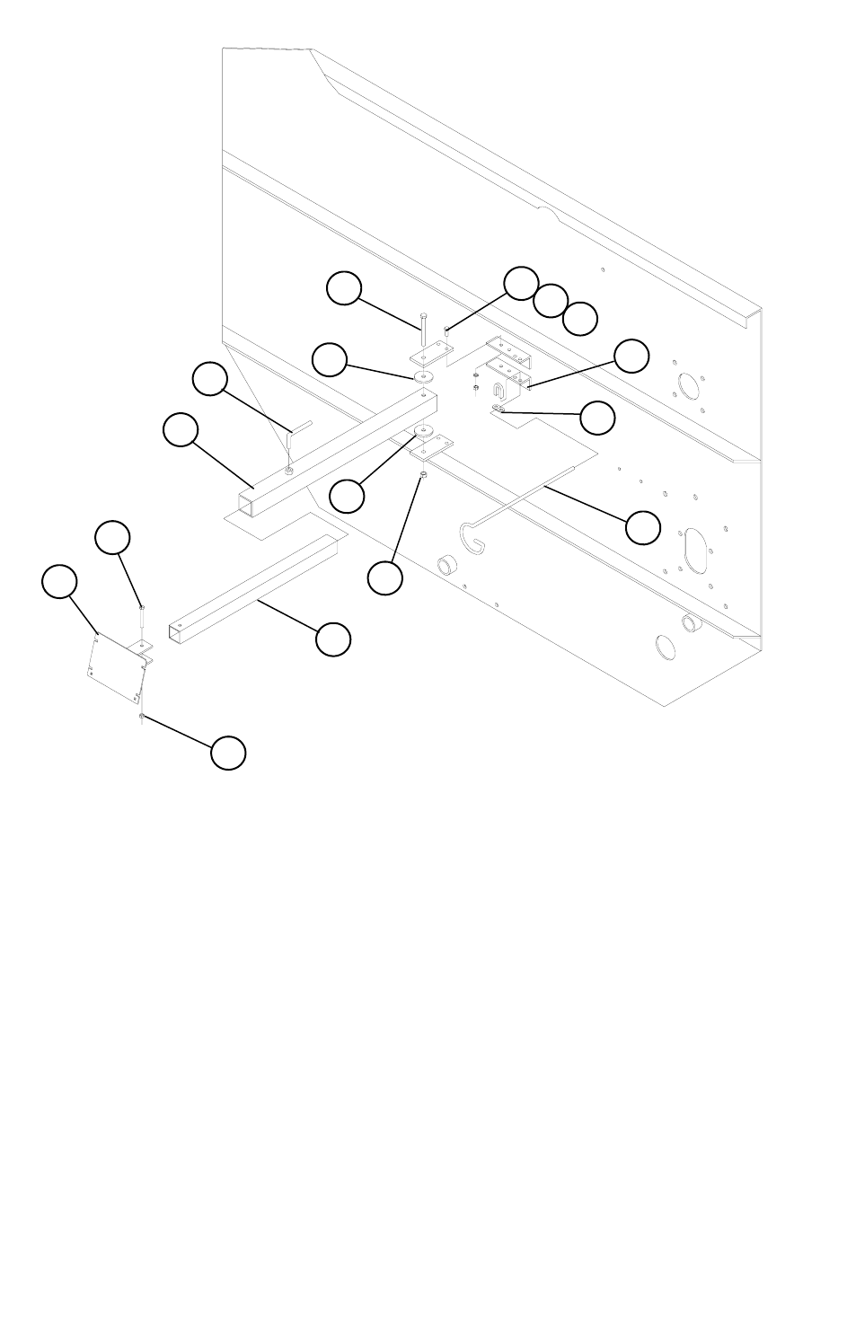
52
524-15 SCALE INDICATOR ASSEMBLY
REF. NO PART NO. DESCRIPTION QTY.
1 872125 TRAILER SCALE ARM WELDMENT ................................... 1
2 872126 TRAILER SCALE INDICATOR WELDMENT....................... 1
3 185490 TRAILER SCALE INDICATOR TUBE ................................... 1
4 185491 HINGE PLATE .......................................................................... 2
5 185493 HINGE WASHER...................................................................... 2
6 185303 TRAILER SCALE ARM ANGLE............................................. 2
7 184283 HOSE CARRIER ....................................................................... 1
8 185492 LOCKING HANDLE 1/2”......................................................... 1
9 401108 HEX LOCKNUT, 1/2”............................................................... 1
10 405714 HHCS, 1/2” x 4-1/2” .................................................................. 1
11 400206 HEX NUT, 3/8”.......................................................................... 4
12 402006 LOCKWASHER, 3/8” ............................................................... 4
13 405653 HHCS, 3/8” x 1”......................................................................... 4
14 400906 HEX LOCKNUT, 3/8”............................................................... 4
15 405661 HHCS, 3/8” x 3”......................................................................... 1
16 412205 CABLE CLAMP, 3/8” ............................................................... 1
2
1
3
4
5
7
8
6
9
10 11 12 13
16
15
14
53
REF. NO PART NO. DESCRIPTION QTY.
1 351056 RUBBER BULB SEAL, 5/32” ................................................ 27’
2 370323 LEVELING PAD ....................................................................... 4
3 370322 HANDLE STOP......................................................................... 2
4 370321 CAM LOCK BUSHING ............................................................ 2
5 370320 HANDLE CAM LOCK.............................................................. 2
6 370319 CAM LOCK HANDLE.............................................................. 2
7 370317 CAM LOCK BOTTOM PLATE................................................ 4
8 370316 CAM LOCK TOP PLATE ......................................................... 4
9 189503 CAM LOCK SPACER...............................................................4
10 872639 OIL BATH CENTER CHANNEL............................................. 1
11 850585 524 LARGE OIL BATH DOOR................................................ 1
12 850586 514 SMALL OIL BATH DOOR................................................ 1
13 850575 CAM ROD, LEFT DOOR.......................................................... 1
14 850574 CAM ROD, RIGHT DOOR.......................................................1
524-15 OIL BATH DOOR ASSEMBLY
11
1
13 14
5
4
10
6
3
8
12
7
2
1
9
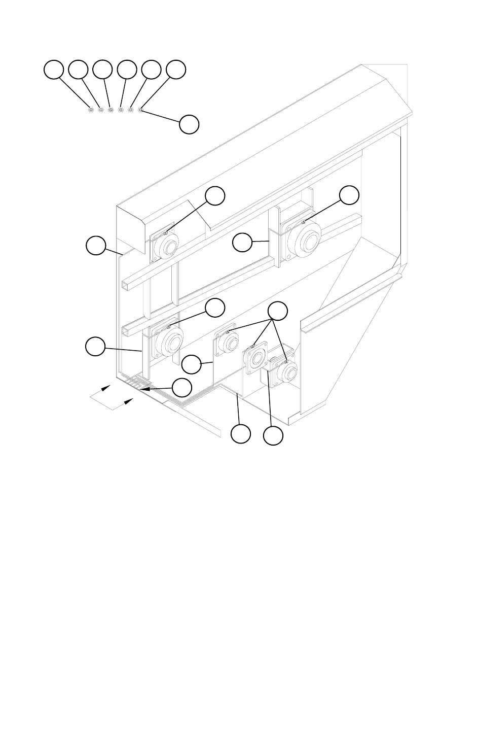
54
524-15 LUBRICATION ASSEMBLY
REF. NO PART NO. DESCRIPTION QTY.
1 310750 1/8” PTF GREASE ZERK ......................................................... 6
2 356001 1/8” NFPT x 3/16” COMP. 90°................................................. 12
3 150212 3/16” COPPER GREASE LINE X 69”...................................... 2
A INPUT SHAFT BEARING
E ROTOR BEARING
4 185044 3/16” COPPER GREASE LINE X 39”...................................... 1
B FRONT JACKSHAFT BEARING
5 185341 3/16” COPPER GREASE LINE X 48”...................................... 2
C REAR JACKSHAFT BEARING
D TOP AUGER BEARING
6 150211 3/16” COPPER GREASE LINE X 18”...................................... 1
F BOTTOM AUGER BEARING
A
A
VIEW A-A
A B C D E F
1
2
3
2
5
2
6
2
5
4
2
3
55
524-15 STAGGERED ROTOR
REF. NO PART NO. DESCRIPTION QTY.
1 190338 WIPER CHANNEL 12-13/16"x32"..........................................18
2 190339P PLASTIC WIPER 10-7/8" x 35-1/4" ........................................ 18
3 407322 ELEVATOR BOLT PLTD 3/8" x 1-1/4"................................. 108
4 401106 3/8" - 16 HEX NYLOC NUT #5 PLTD................................... 108
5 402406 FLAT WASHER, 3/8" ID x 1" OD ......................................... 108
6 407102 CAR BOLT, 1/2"-13 X 1-1/2" .................................................. 72
7 400908 1/2"-13 HEX-C LOCKNUT...................................................... 72
8 402408 FLAT WASHER, 1/2" ID x 1-3/8" OD .................................... 72
9 850544 524 ROTOR SHAFT FLANGE WA ......................................... 1
10 872874 524-15 STAGGERED ROTOR WA.......................................... 1
11 780078 STAGGERED WIPER BUNDLE (INCLUDES 1 THRU 8) .... 1
9
10
7
8
1
2
3
4
6
5
56
3 ARM ROTOR ASSEMBLY
(FROM SERIAL #890573481 TO PRESENT)
REF. NO PART NO. DESCRIPTION QTY.
1 850122 524 3-ARM ROTOR WELDMENT .......................................... 1
2 850125 524 WIPER TUBE WELDMENT ............................................. 3
3 850007 ROTOR SPRING COVER WELDMENT................................. 6
4 150344 END WIPER STRAP.................................................................6
5 150343 CENTER WIPER STRAP.......................................................... 3
6 150346 END PLASTIC WIPER ............................................................. 6
7 150345 CENTER PLASTIC WIPER...................................................... 3
8 410005 2 1/2” X 24” X .410” COMPRESSION SPRING...................... 6
9 406489 3/4”-10 x 6” HHCS .................................................................... 6
10 400912 3/4”-10 HEX CTR LOCKNUT.................................................. 6
11 401106 3/8”-16 NYLOCK HEX NUT................................................... 66
12 405654 3/8”-16 x 1-1/4” HHCS.............................................................66
13 850544 ROTOR SHAFT FLANGE WELDMENT ................................ 1
14 750030 WIPER ASSEMBLY (INCLUDES #’s 2,4,5,6,7,11& 12)..... 3
1
13
9
10
6
11
2
8
3
12
4
5
7
57
5 ARM ROTOR ASSEMBLY
(FROM SERIAL #890573481 TO PRESENT)
REF. NO PART NO. DESCRIPTION QTY.
1 850248 524 5-ARM ROTOR WELDMENT .......................................... 1
2 850125 524 WIPER TUBE WELDMENT ............................................. 5
3 850007 ROTOR SPRING COVER WELDMENT................................ 10
4 150344 END WIPER STRAP................................................................10
5 189343 CENTER WIPER STRAP.......................................................... 5
6 150346 END PLASTIC WIPER ............................................................ 10
7 150345 CENTER PLASTIC WIPER...................................................... 5
8 410005 2 1/2” x 24” X .410” COMPRESSION SPRING .....................10
9 406489 5/8”-10 x 6” HHCS ................................................................... 10
10 400912 3/4”-10 HEX CTR LOCKNUT................................................. 10
11 401106 3/8”-16 NYLOCK HEX NUT.................................................. 110
12 405654 3/8”-16 x 1-1/4” HHCS............................................................110
13 850544 ROTOR SHAFT FLANGE WELDMENT ................................ 1
14 750030 WIPER ASSEMBLY (INCLUDES #’s 2,4,5,6,7,11 &12)..... 5
1
3
8
9
10
13
2
7
12
4
5 11
6
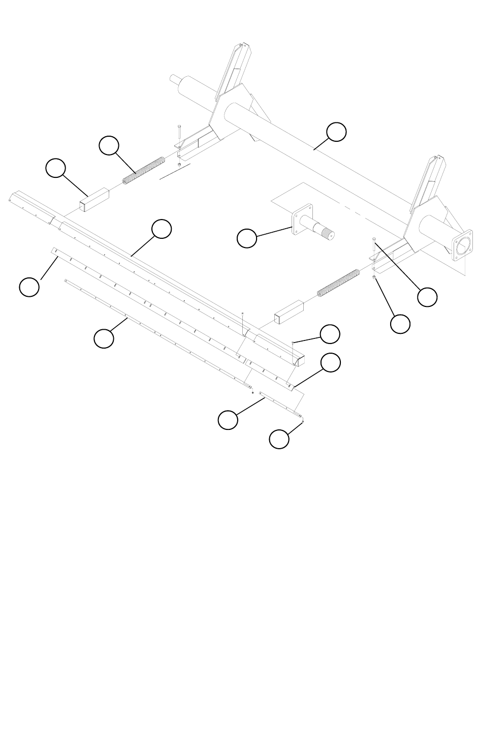
58
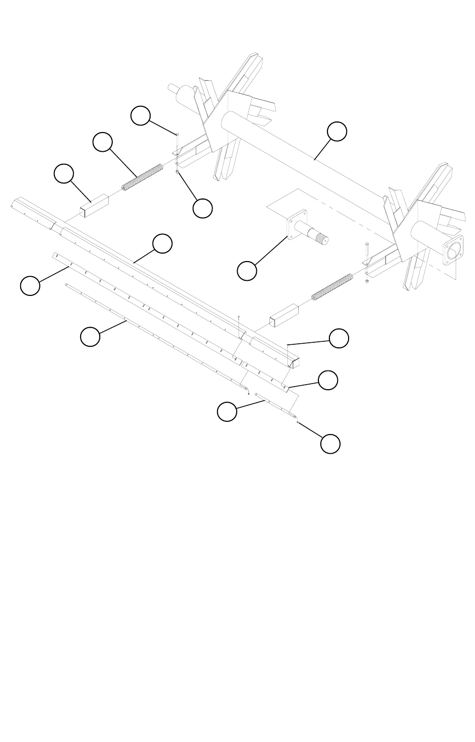
REF. NO PART NO. DESCRIPTION QTY.
1 850131 TOP AUGER 3/8” FLIGHT WELDMENT ..........................1
2 382026 FLIGHT RH 20”OD x 6 5/8”ID x 3/8” x 14” PITCH ............9-1/2
3 150126 TOP AUGER PADDLE............................................................. 3
4 850542 TOP AUGER SHAFT FLANGE WELDMENT ....................... 1
5 850131B TOP AUGER DOUBLE FLIGHT WELDMENT................. 1
6 382026 FLIGHT RH 20”OD x 6-5/8”ID x 3/8” x 14” PITCH .............. 11
7 381625 FLIGHT RH 16”OD x 6-5/8”ID x 1/4” x 14” PITCH .............. 11
8 382023 FLIGHT LH 20”OD x 6-5/8”ID x 3/8” x 20” PITCH ............ 1/2
9 150126 TOP AUGER PADDLE............................................................. 3
10 850127 BOTTOM AUGER 1/2” FLIGHT WELDMENT................. 1
11 382021 FLIGHT LH 20”OD x 6-5/8”ID x 1/2” x 20” PITCH ............... 7
12 382020 FLIGHT RH 20”OD x 6-5/8”ID x 1/2” x 20” PITCH ............... 1
13 150411 20” AUGER KICKER................................................................ 2
14 850543 BOTTOM AUGER SHAFT FLANGE WELDMENT .............. 1
BOTTOM AUGER
TOP AUGER
5
4
8
7
9
12 6
3
1
2
TOP AUGER
(OPTIONAL)
13
14
11
10
524 TOP & BOTTOM AUGER ASSEMBLIES
(FROM SERIAL #890573481 TO PRESENT)
59
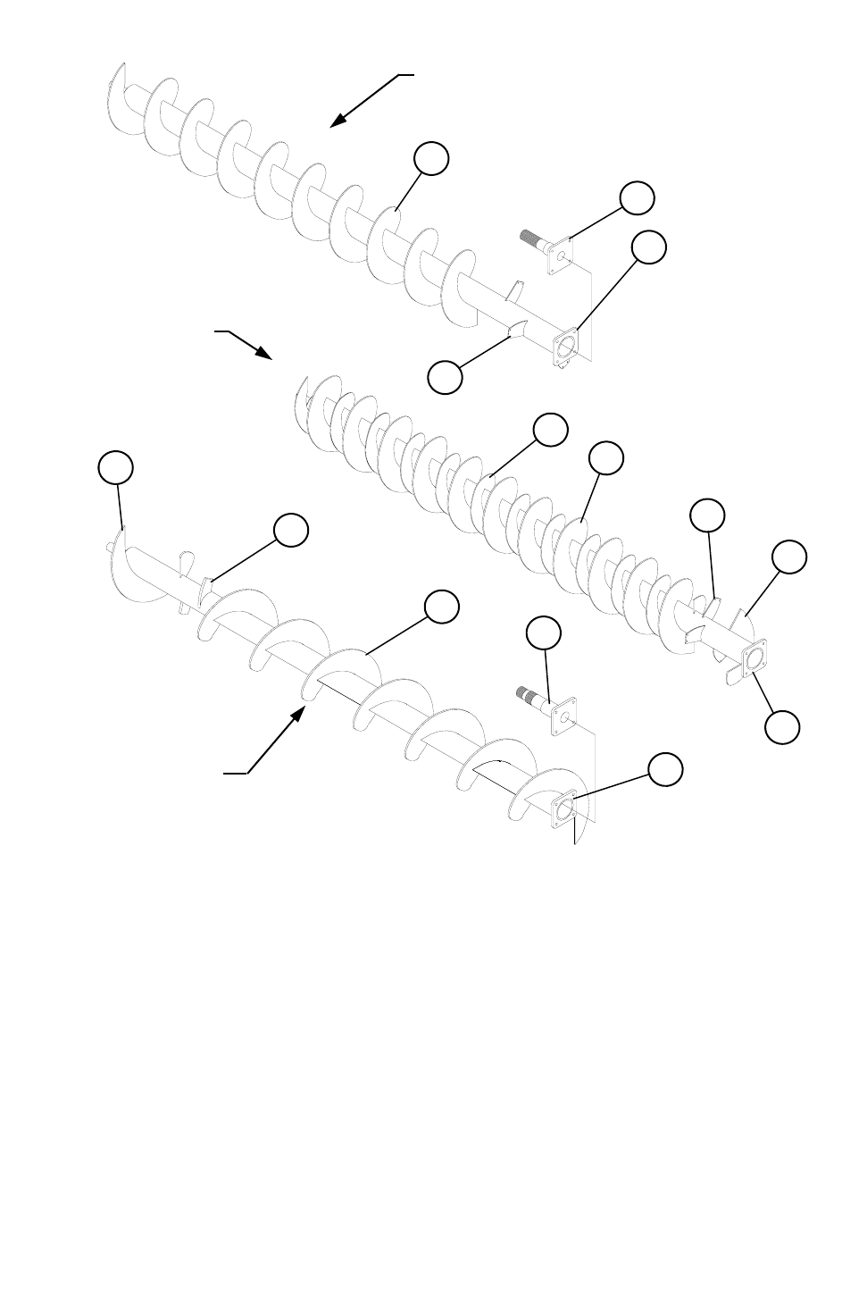
524 FRONT END ASSEMBLY
(FROM SERIAL #890573481 TO PRESENT)
REF. NO PART NO. DESCRIPTION QTY.
1 340436 LB F3Y235N 2-3/16” 4-BOLT FLANGE BEARING .............. 1
2 340437 LB F3Y239N 2-7/16” 4-BOLT FLANGE BEARING .............. 1
3 340446 LB F247 2-15/16” 4-BOLT FLANGE BEARING .................... 1
3 1
2

60
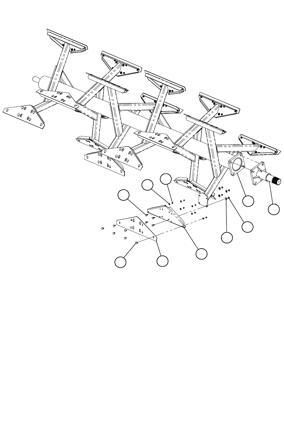
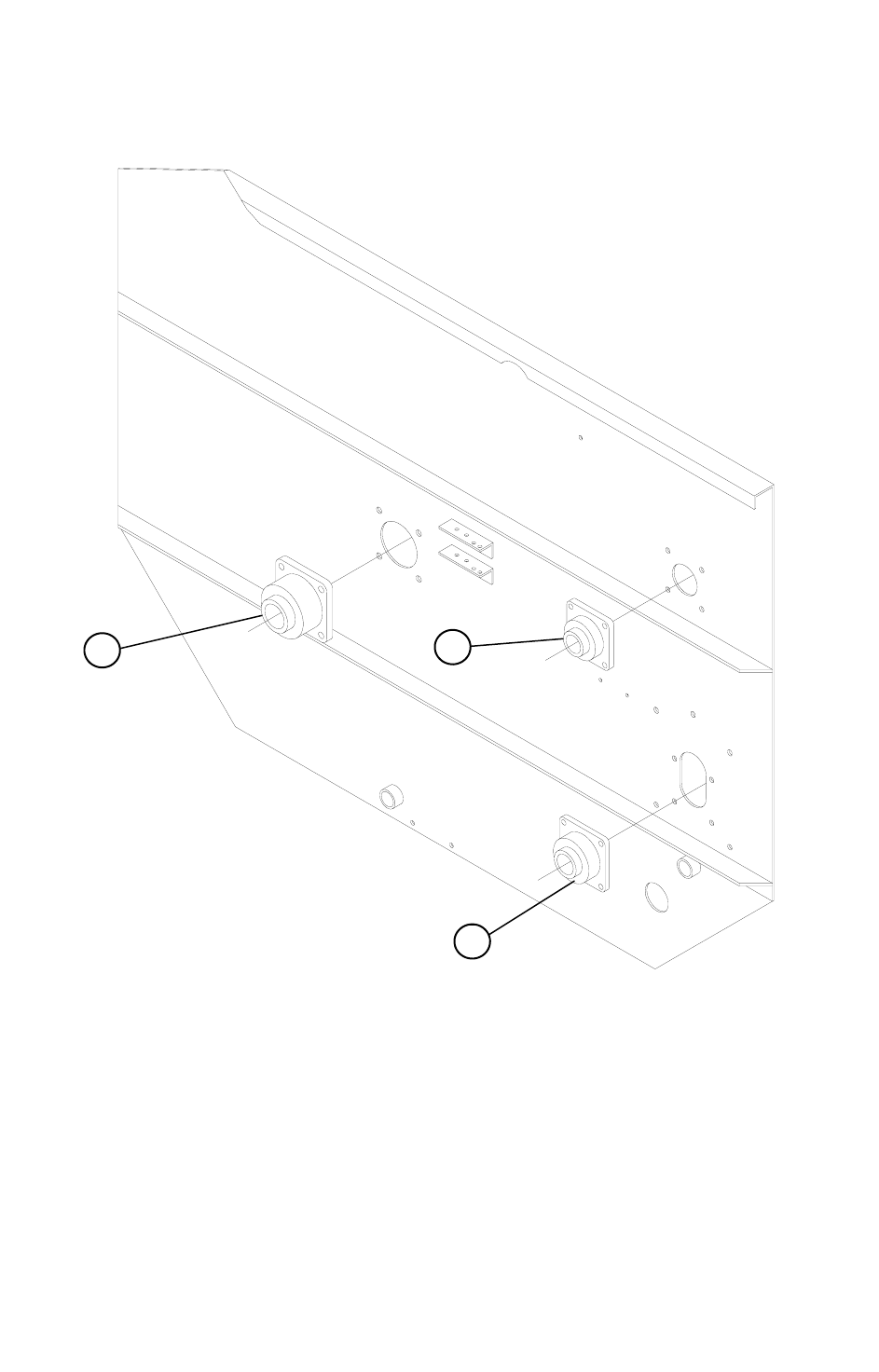
524 DRIVE ASSEMBLY (FROM SERIAL #890573481 TO PRESENT)
1
2
3
4
5
6
8
10
9
30
28
15
14
12
10
9
24
13
20
18
17
16
19
21
29
11
31
26
9
10
25
24
23
22
27
21
43
43 37
40
36 34
32
33
42
37
40
34
33
34
42
38
43
41
33
34
43 37
39
35
42
11
7
8

61
524 DRIVE ASSEMBLY (FROM SERIAL #890573481 TO PRESENT)
REF# PART# DESCRIPTION QTY.
1 340556 3-1/2” MSF 56 4-BOLT FLANGE BRG........ 1
2 189545 3-1/2” SHAFT SPACER-13/32 ...................... 1
3 850519 #120 B 48 SPROCKET WELDMENT........... 1
4 189546 3” SHAFT SPACER-3/8................................. 1
5 185319 3-1/2” SHAFT SPACER-1/2 .......................... 1
6 331213 #120 B 13H SPROCKET................................ 1
7 150599 2-1/2” SHAFT SPACER-1/16 ........................ 1
8 850129 3-1/2” RETAINER WELDMENT .................. 2
9 402010 5/8” LOCKWASHER ..................................... 3
10 405754 5/8” x 2” HHCS............................................... 3
11 340438 2-7/16” RCJ 4-BOLT FLANGE BRG ............ 2
12 331002 #100 B 17H SPRKT - 540 PTO TRK & TRL
331001 #100 B 15H SPRKT - 1000 PTO TRL ........... 1
13 189104 5/8” SQ. KEY x 1-3/4 ..................................... 3
14 150363 JACKSHAFT .................................................. 1
15 330849 #80 B 48 SPROCKET..................................... 1
16 781037 2-7/16” SEAL PLATE ASSEMBLY.............. 1
A 355039 2-7/16” SEAL CR-24287 ................................ 2
17 340439 2-7/16” RCJC 4-BOLT FLANGE BRG ......... 1
18 330825 #80 B 25H SPRKT - 540 PTO TRK & TRL ...
330805 #80 B 15H SPRKT - 1000 PTO TRL ............. 1
19 342048 3” REX MB 2300 BEARING 4-BOLT .......... 1
REF# PART# DESCRIPTION QTY.
20 850521 #100 B 54 SPRKT WELDMENT ...............1
21 850520 #120 B 26 SPROCKET WELDMENT .......1
22 340564 4” MSF 64 BEARING ................................1
23 185321 4” SHAFT SPACER 1/2 ............................1
24 850518 #120 B 100 SPROCKET WELDMENT .....1
25 185329 4-1/2” RETAINER .....................................1
26 150369 524 INPUT SHAFT ...................................1
27 340228 VCJT 1-3/4” 2-BOLT FLANGE BRG.........1
28 320884 #80 RC x 84 PITCHES .............................1
29 321111 #100 RC x 111 PITCHES .........................1
30 321225 #120 RC x 125 PITCHES .........................1
31 321275 #120 RC x 75 PITCHES ...........................1
32 410851 3/8” x 6” EYEBOLT ...................................1
33 410852 3/8” x 8” EYEBOLT ...................................3
34 410012 1-3/4” x 7” PULL SPRING.........................4
35 185487 2/0 PASSING LINK CHAIN x 3 .................1
36 185488 2/0 PASSING LINK CHAIN x 18 ...............1
37 872252 IDLER ARM WELDMENT 23-3/4..............3
38 872254 IDLER ARM WELDMENT 13....................1
39 185582 IDLER BLOCK 3-1/2”OD UHMW..............1
40 185621 #120 IDLER BLOCK UHMW.....................2
41 187159 #100 IDLER BLOCK UHMW.....................1
42 187157 PULL TAB .................................................4
43 412416 1” SET COLLAR .......................................8
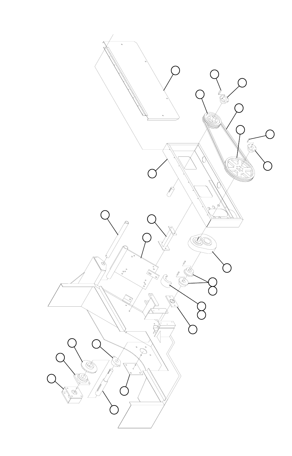
62
524 STATIONARY DRIVE ASSEMBLY
1
2
21
22
23
24
3
4 7
5 6
8
18
19
20
17
12
14
16
15
13
9
11
10

63
REF. NO PART NO. DESCRIPTION QTY.
1 150395 524 ELECTRIC INPUT SHAFT - 17..........................................1
2 185641 COVER PLATE .........................................................................1
3 780015 1-3/4” SEAL PLATE ASSEMBLY..............................................1
A 355028 1-3/4” GREASE SEAL...............................................................2
4 320720 #60-2 RC x 20 PITCHES COMP...............................................1
5 332612 60 B 20 x 1-3/4” CHAIN COUPLING SPROCKET ....................2
6 185480 3/8” SQ. KEY x 2”......................................................................2
7 332614 6020 CHAIN COUPLING COVER.............................................1
8 344023 3:1 HUB CITY GEARBOX.........................................................1
9 324016 5V-2 GROOVE 16.0” SF BELT SHEAVE..................................1
10 336022 SF 1-3/8” QD BUSHING............................................................1
11 185484 5/16” SQ. KEY x 2”....................................................................1
12 781001 ELEC. BELT SHIELD DOOR ASSEMBLY................................1
13 325106 5V-1060 V-BELT .......................................................................2
14 324009 5V-3 GROOVE 9.25” SF BELT SHEAVE..................................1
15 336031 1-7/8” SQ BUSHING .................................................................1
16 185485 1/2” SQ. KEY x 2-1/2”................................................................1
17 850149 524 ELEC BELT SHIELD WELDMENT ....................................1
18 872003 ELEC. BELT SHIELD SUPPORT WELDMENT........................1
19 850147 524 ELEC. MOTOR BASE WELDMENT 25-50 ........................1
20 185087 ELEC. MOTOR PIVOT PIPE 24” ..............................................1
21 340228 VCJT 1-3/4” 2-BOLT FLANGE BEARING.................................1
22 330825 80 B 25H RC SPROCKET ........................................................1
23 340439 RCJC 2-7/16” 4-BOLT FLANGE BEARING ..............................1
24 781037 INPUT BEARING MOUNT & SEAL ASSEMBLY ......................1
A 355039 CR-24287 2-7/16”ID SEAL........................................................2
524 STATIONARY DRIVE ASSEMBLY

64
524 200 SERIES 3:1 GEARBOX ASSEMBLY (#344023)
REF. NO PART NO. DESCRIPTION QTY.
1 344214 CLOSED END CAP...................................................................2
2 344215 END CAP GASKET .................................................................. 4
3 344211 BOX BEARING CUP 18620 ..................................................... 4
4 344210 GEARBOX BEARING 1-3/4” T-18690....................................4
5 344220 3:1 LOW SPEED GEAR............................................................ 1
6 344213 OPEN END CAP 02-23-00166-400.......................................... 2
7 344209 GEARBOX SEAL 1 3/4” CR 18039..........................................2
8 344223 LOW SPEED SHAFT 1 3/4” ..................................................... 1
9 344219 3:1 1-3/8” HIGH SPEED SHAFT & GEAR COMPLETE........ 1
10 344212 CENTER CASE GASKET 02-23-00919-200........................... 1
10
9
8
7 6
5
4
3
9 2
1
2
2
3
3
3
4
4
4
6
7
1
2
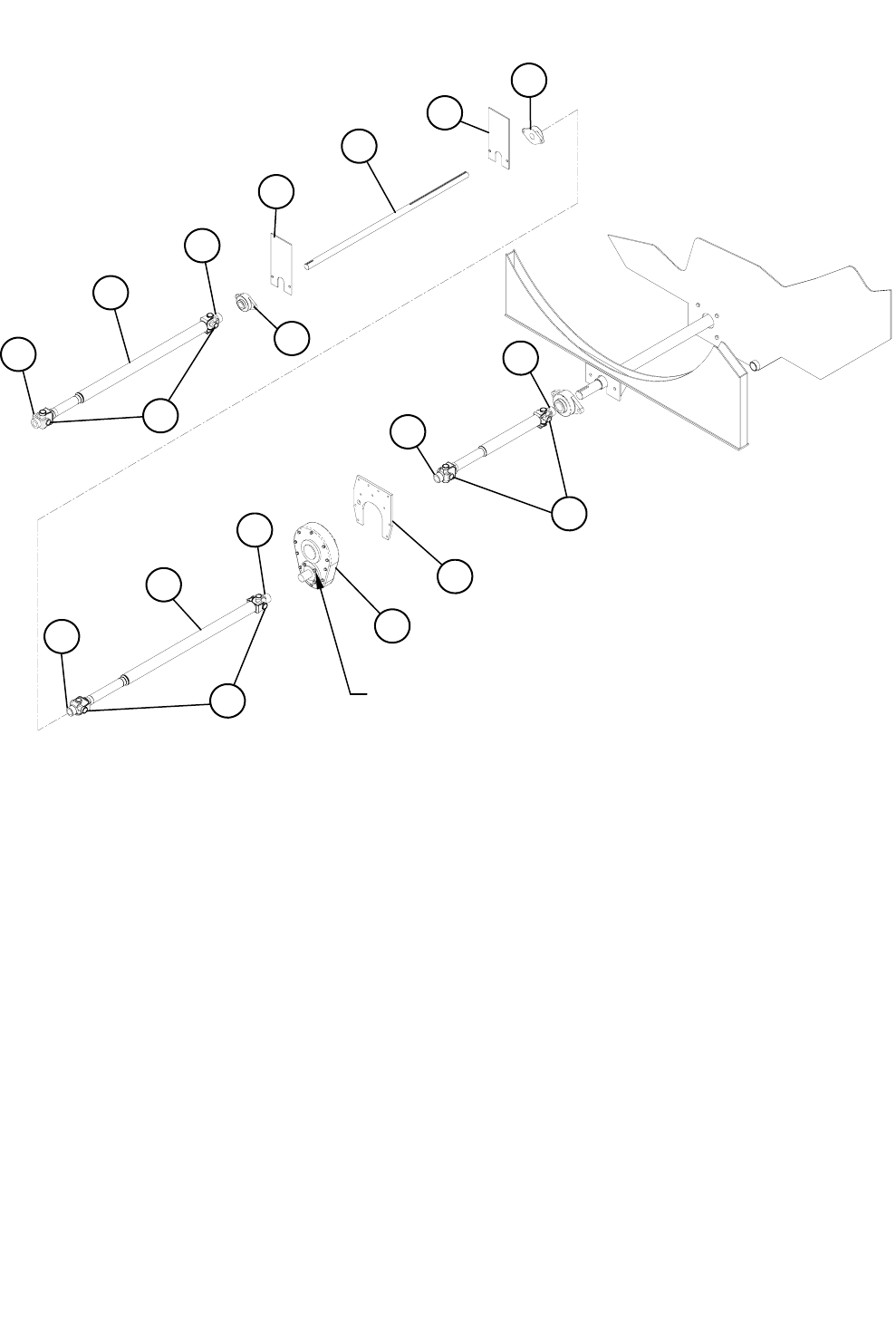
65
524 TRUCK DRIVELINE ASSEMBLY
REF. NO PART NO. DESCRIPTION QTY.
1 780486 1280 DRIVESHAFT ASSY. 1-1/4” x 1-3/8” ............................. 1
A 338420 1-1/4” SPICER YOKE............................................................... 1
B 338435 SPICER 1280 CROSS KIT....................................................... 2
C 338053 SPICER DRIVESHAFT SPLINE TUBE ASSY ......................... 1
D 338422 1-3/8” SPICER YOKE............................................................... 1
2 183327 TRUCK JACKSHAFT 1-3/8”..................................................... 1
3 340221 1-3/8” FX3W222E 2-BOLT FLANGE BEARING ...................... 2
4 183319 TRUCK JACKSHAFT BRACKET ............................................. 2
5 780494 1280 DRIVESHAFT ASSY 1-3/8” x 1-3/8” ............................... 1
A 338422 1-3/8” SPICER YOKE............................................................... 2
B 338435 SPICER 1280 CROSS KIT....................................................... 2
C 338053 SPICER DRIVESHAFT SPLINE TUBE ASSY ......................... 1
6 344023 3:1 HUB CITY GEARBOX........................................................ 1
7 183251 GEARBOX PLATE ................................................................... 1
8 338042 W-2400 385560 DRIVESHAFT ................................................ 1
A 338449 W-2400 YOKE 1-3/4” RB, 1/2 SET SCREW ............................ 1
B 338443 W-2400 312410 CROSS KIT ................................................... 2
C 338451 W-2400 1-3/4” RB YOKE, SET SCREW & BOLT .................... 1
1D
1B
1A
1C
3
4
2
4
3
5A
5A
5C
5B
6
7
CHECK OIL HERE
8B
8A
8C
ITEMS 1 & 5 ARE CUT TO LENGTH
AND WELDED AT INSTALLATION.
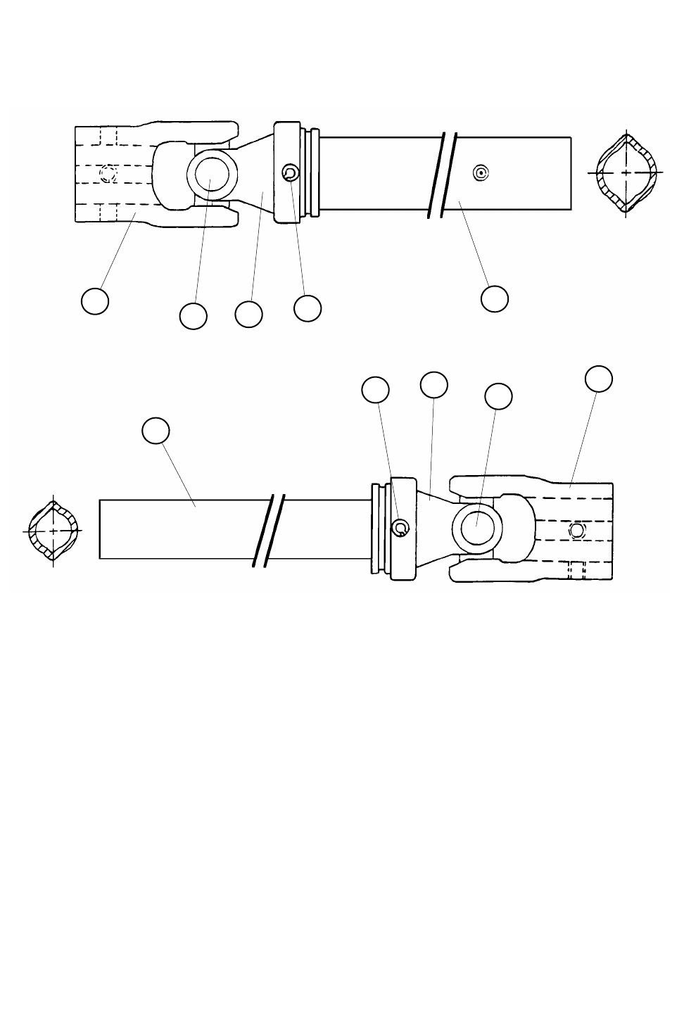
66
8
7
6
5
4
3
2
1
2
3
REF. NO PART NO. DESCRIPTION QTY.
1 338451 W-2400 YOKE 1-3/4”RB 3/8” KEYWAY ...................................1
2 338443 W-2400 CROSS KIT................................................................. 2
3 338473 WALTERSHIED #10 METRIC ROLL PIN................................. 2
4 338450 W-2400 INBOARD YOKE......................................................... 1
5 338447 W-2400 OUTER PROFILE 2aL ................................................ 1
6 338448 W-2400 INNER PROFILE 1b.................................................... 1
7 338452 W-2400 INBOARD YOKE 2A ...................................................1
8 338449 W-2400 YOKE 1-3/4”RB 3/8” KEYWAY ................................... 1
524 TRUCK W-2400 DRIVESHAFT ASSEMBLY (#385560)
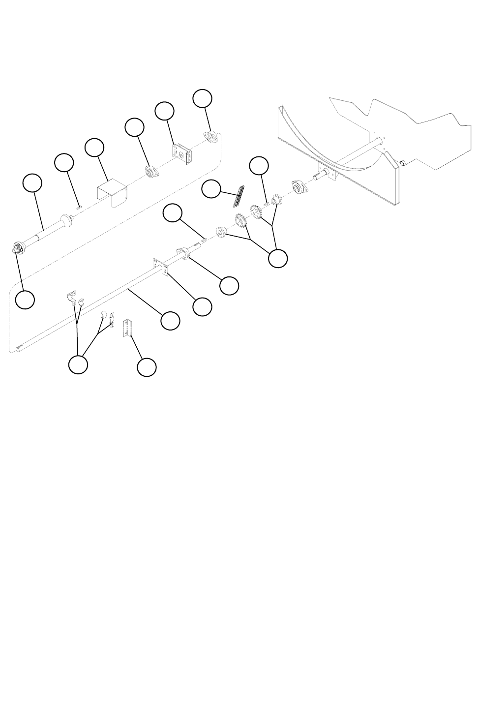
67
REF. NO PART NO. DESCRIPTION QTY.
1 332612 60 B 20 x 1-3/4” CHAIN COUPLING SPRKT ........................... 2
2 185480 3/8” SQ. KEY x 2”..................................................................... 3
3 320720 #60-2 RC x 20 PITCHES COMP .............................................. 1
4 340229 1-3/4” FX3W228U 2-BOLT FLANGE BEARING ...................... 3
5 183277 BEARING HANGER TRAILER UNIT ....................................... 1
6 341028 1-3/4” PABCO BKP28T-TP W/BRG ......................................... 1
7 150386 524 DRIVELINE-147” ............................................................... 1
8 850136 524 TRAILER BEARING PLATE WELDMENT ........................ 1
9 185299 CARRIER BEARING ANGLE ................................................... 1
10 780601 PTO SHIELD ASSEMBLY........................................................ 1
11 338030 W-2400 383399 DRIVESHAFT-540......................................... 1
12 338442 W-2400 019516 YOKE 1000 RPM........................................... 1
540 & 1000 TRAILER PTO DRIVELINE ASSEMBLY
4
8
4
10
2 2
3
2
4
5
7
11
12
9
6
1
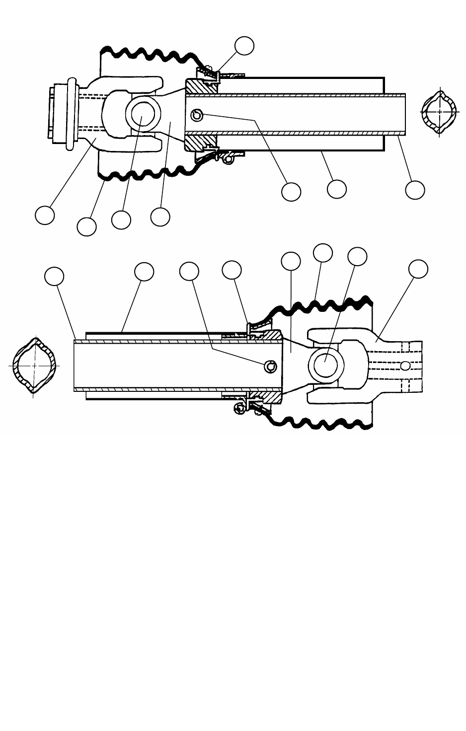
68
524 TRAILER DRIVESHAFT W-2400 (#383399)
REF. NO PART NO. DESCRIPTION QTY.
1 YOKE (TRACTOR END)
A 338444 YOKE 540 RPM .......................................................................1
B 338442 YOKE 1000 RPM ..................................................................... 1
2 338443 CROSS KIT ............................................................................... 2
3 338473 ROLL PIN METRIC #10 ........................................................... 2
4 338450 INBOARD YOKE (TRACTOR END) ...................................... 1
5 338474 INNER PROFILE (TRACTOR END) ....................................... 1
6 338467 OUTER PROFILE (MIXER END)............................................ 1
7 338452 INBOARD YOKE (MIXER END)............................................1
8 338449 YOKE (MIXER END) ............................................................... 1
9 338486 SHIELD CONE 9-RIB...............................................................2
10 338487 OUTER SHIELD TUBE (TRACTOR END) ............................1
11 338488 INNER SHIELD TUBE (MIXER END) ................................... 1
12 338489 BEARING RING ....................................................................... 2
12
1
9 2 4
3 10 5
6 11 3 7 2
8
9
12
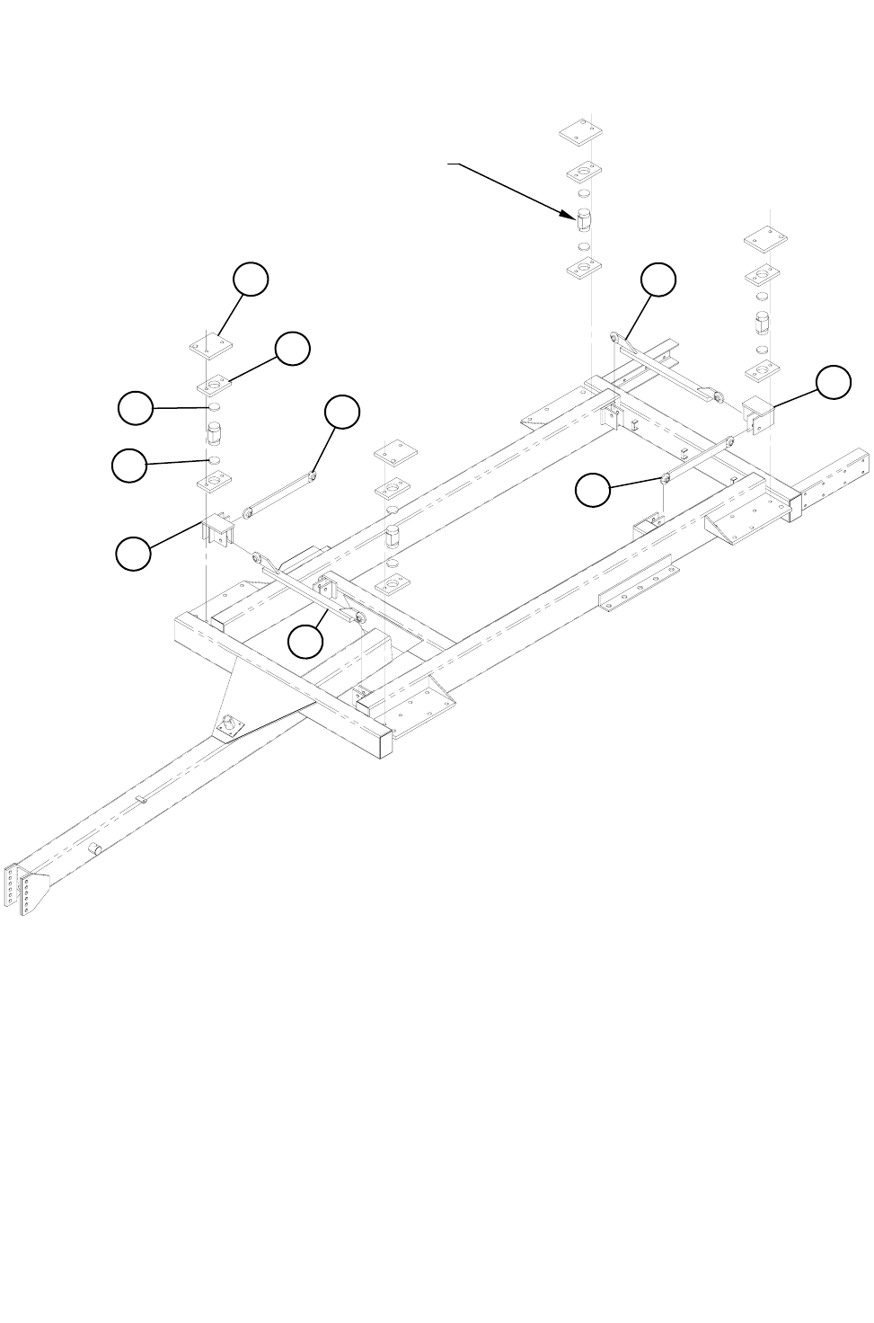
69
REF. NO PART NO. DESCRIPTION QTY.
1 182881 SCALE MOUNT MIXER PAD................................................... 4
2 182915 LOADCELL CAGE PLATE ....................................................... 8
3 185997 3/8” SCALE PAD ...................................................................... 8
4 870501 CHECK ROD WELDMENT ...................................................... 2
5 872245 OFFSET CHECK ROD WELDMENT ....................................... 2
6 870519 MIXER SCALE CHECK WELDMENT ...................................... 2
524 TRAILER LOADCELL SCALE PARTS
LOADCELL
1
2
4
3
3
6
5
4
5
6
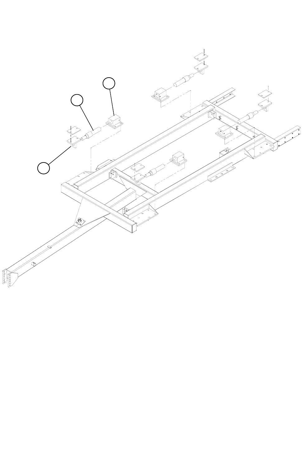
70
524 TRAILER WIEGH BAR ASSEMBLY
REF. NO PART NO. DESCRIPTION QTY.
1 189294 WEIGH BAR MIXER PAD ........................................................ 4
2 872360 2-1/2” T-BAR WELDMENT ....................................................... 4
3 860055 2-1/2” BAR BLOCK WELDMENT ............................................. 4
3
2
1
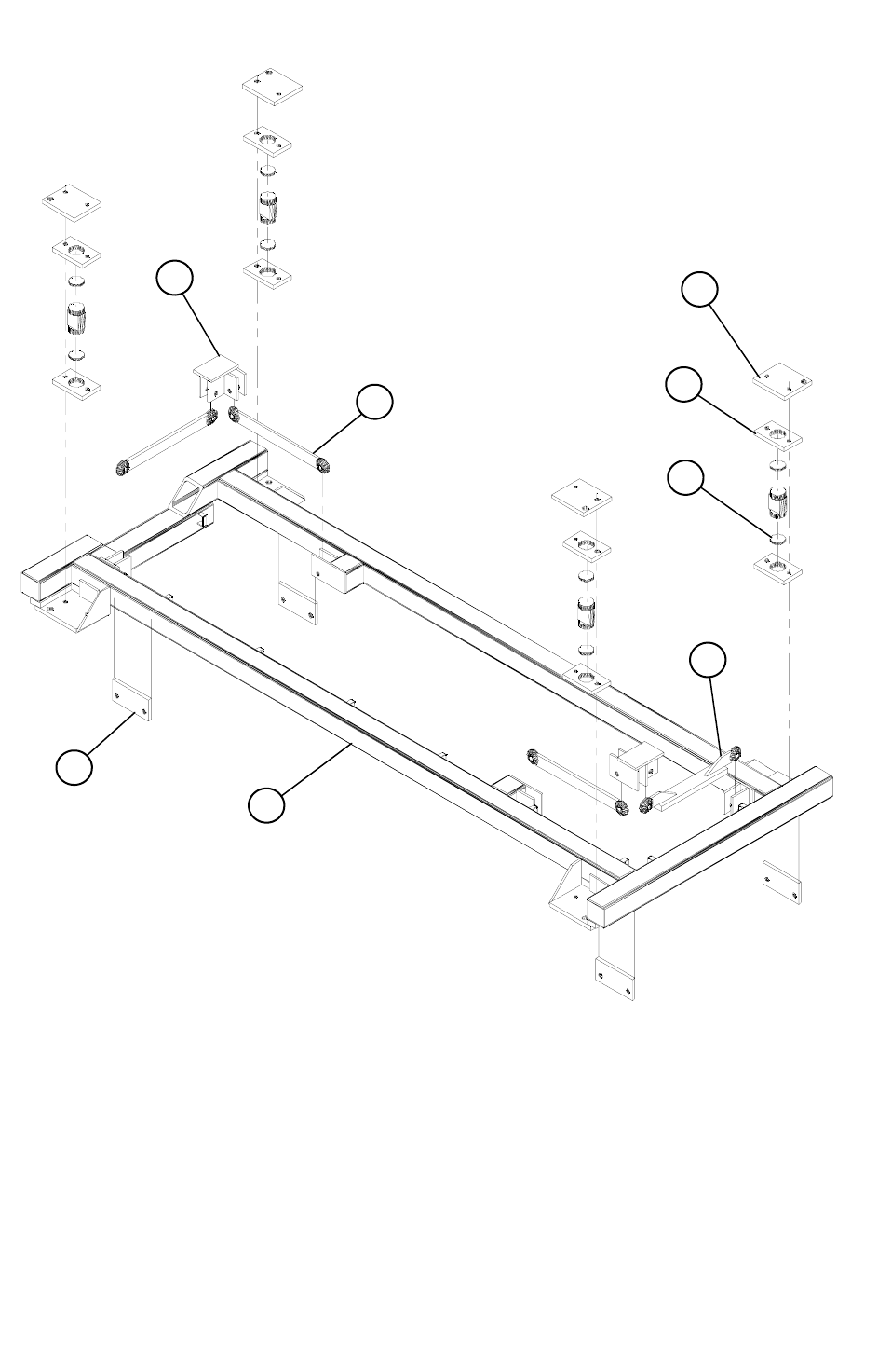
71
524 TRUCK SCALE FRAME ASSEMBLY
REF. NO PART NO. DESCRIPTION QTY.
1 870527 SCALE FRAME WELDMENT................................................... 1
2 182998 TRUCK FRAME BRACKET...................................................... 4
3 870519 MIXER CHECK WELDMENT................................................... 2
4 872053 OFFSET CHECK ROD............................................................. 1
5 870501 CHECK ROD ............................................................................ 3
6 182881 SCALE MOUNT MIXER PLATE............................................... 4
7 182915 LOADCELL CAGE PLATE ....................................................... 8
8 185997 SCALE PAD ............................................................................. 8
5
2
1
6
7
8
4
3
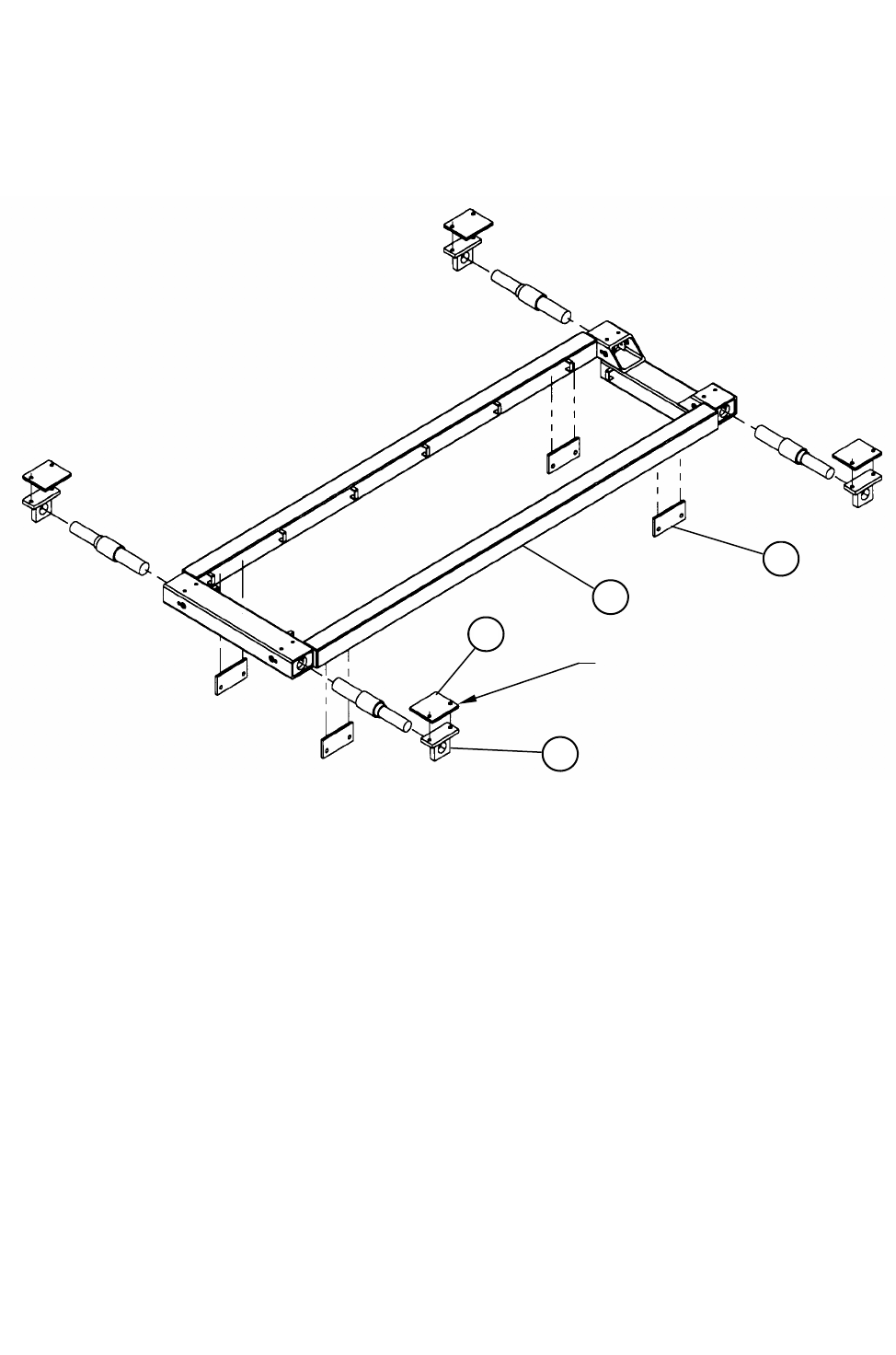
72
524 TRUCK 2-1/2” WEIGH BAR SCALE FRAME ASSEMBLY
REF. NO PART NO. DESCRIPTION QTY.
1 872163 524 TRUCK WEIGH BAR FRAME......................................... 1
2 872159 2-1/2” WEIGH BAR MOUNT WELDMENT .......................... 4
3 182998 TRUCK FRAME BRACKET.................................................... 4
4 185609 BART MOUNT MIXER PAD................................................... 4
1
3
4
2
WELDED TO MIXER BASE
AT INSTALLATION
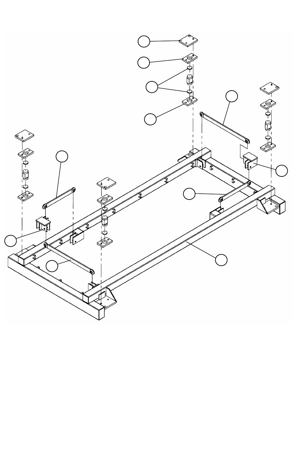
73
524 STATIONARY LOAD CELL SCALE FRAME ASSEMBLY
5
6
6
7
4
2
3
2
3
4
1
REF. NO PART NO. DESCRIPTION QTY.
1 850150 524 STATIONARY SCALE FRAME WELDMENT ................... 1
2 870501 SCALE CHECK ROD WELDMENT ......................................... 2
3 871053 TRAILER CHECK ROD WELDMENT ...................................... 2
4 870519 MIXER SCALE CHECK WELDMENT ...................................... 2
5 182881 SCALE MIXER MOUNT PLATE............................................... 4
6 182915 LOADCELL CAGE PLATE ....................................................... 8
7 185997 SCALE PAD ............................................................................. 8
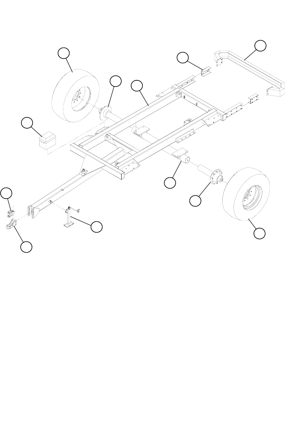
74
524 TRAILER ASSEMBLY
REF. NO PART NO. DESCRIPTION QTY.
1 781145 18.5 x 22.5 MOUNTED TIRE ASSEMBLY ............................... 2
2 651024 PERFECT HITCH KIT (INCLUDES 2A & 2B)...........................1
2A 374100 BASE HITCH BODY ................................................................. 1
2B 374101 CLEVIS INSERT ....................................................................... 1
3 357400 BATTERY BOX WITH STRAP.................................................. 1
4 870972 TRAILER AXLE WELDMENT ................................................... 1
5 870733 TRAILER BUMPER WELDMENT............................................. 1
6 184598 TRAILER BUMPER EXTENSION............................................. 2
7 870931 TRAILER FRAME WELDMENT................................................ 1
8 750111 TRAILER HUB & SPINDLE - 10 BOLT LEFT HAND................ 1
9 840110 TRAILER HUB & SPINDLE - 10 BOLT RIGHT HAND ............. 1
10A 374002 5000 LB. G&G JACK ................................................................1
10B 374001 9000 LB. DROP LEG JACK...................................................... 1
5
6
7
9
1
3
2B
2A
10
4
8
1

75
REF. NO PART NO. DESCRIPTION QTY.
1 342213 BEARING, 3.543” BORE, TIMKEN #HM 218248..................... 1
2 342214 BEARING, 2.625” BORE, TIMKEN #HM 212049..................... 1
3 342215 BEARING CUP, 5.787” OD, TIMKEN #HM218210.................. 1
4 342216 BEARING CUP, 4.813” OD, TIMKEN #212011 ....................... 1
5 184614 SPINDLE, 4-9/16” x 25-1/2”, 20,000 LB ................................... 1
6 372211 HUB, LEFT HAND, 10-BOLT, 20,000 LB................................. 1
7 372212 HUB, RIGHT HAND, 10-BOLT, 20,000 LB .............................. 1
8 372304 SEAL, 4.563” x 6.001”, #CR43771........................................... 1
9 372309 DUST CAP, 20,000 LB HUB .................................................... 1
10 400033 OUTER NUT, 3/8” THICK x 2-5/8” ID....................................... 1
11 400034 INNER NUT, 3/8” THICK x 3-5/8” ID ........................................ 1
12 400102 LUG NUT, RIGHT HAND, 3/4” ................................................ 10
13 400103 LUG NUT, LEFT HAND, 3/4” .................................................. 10
14 402005 LOCKWASHER, 5/16”.............................................................. 6
15 402904 WASHER, 1/4” THICK x 2-41/64” ID........................................ 1
16 405625 HHCS, 5/16” x 1/2” ................................................................... 6
17 407724 STUD BOLT, 3/4” x 2-9/16”, RIGHT HAND ............................ 10
18 407725 STUD BOLT, 3/4” x 2-9/16”, LEFT HAND............................... 10
5
8
1
3
6 7
4
2
11
15
16
14
9
10 13
12
17 18
10-BOLT HUB & SPINLDE ASSEMBLY (20,000 LB.)
RIGHT HAND ASSY COMPLETE - #750110
LEFT HAND ASSY COMPLETE - #750111
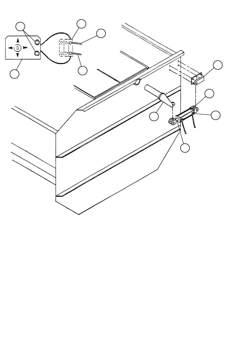
76
524 ROTO-HAY PROCESSOR ASSEMBLY (HYDRAULIC OPTION)
REF. NO PART NO. DESCRIPTION QTY.
1 188226 FEEDER ELECTRIC CONTROL BRACKET............................ 1
2 357702 PUCH BUTTON SWITCH 12V-2 POLE ................................... 1
3 780124 MV5 3rd VALVE ADD ON KIT .................................................. 1
4 780109 CYLINDER ASSY, 2” x 8”......................................................... 1
4A 368007 RESTRICTOR FITTING, 3/8” MP x 3/8” FPSW 90° ................. 2
4B 364954 CYLINDER ROD, 2” x 8” x 1-1/16” DIA .................................... 1
4C 364055 CYLINDER, 2” x 8” STROKE.................................................... 1
4D 354400 REPAIR KIT, 2” HYDRAULIC CYLINDER................................ 1
5 781055 TRUCK TO MIXER WIRE ASSEMBLY .................................... 1
6 850060 HAY PAN HYD. CYL. BRACKET WELDMENT........................ 1
7 872357 HAY PAN HYDRAULIC ARM WELDMENT.............................. 1
8 781070 HYDRAULIC HOSE ASSY, 3/8” x 87” x 3/8” MP ENDS........... 1
9 781097 HYDRAULIC HOSE ASSY, 3/8” x 68” x 38” MP ENDS............ 1
4C
4A
4B
7
6
9
8
3
2
1
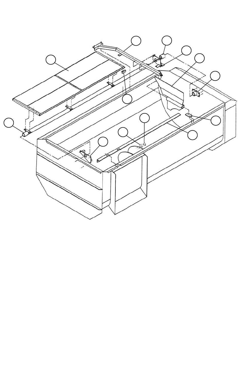
77
524 ROTO-HAY PROCESSOR ASSEMBLY
REF. NO PART NO. DESCRIPTION QTY.
1 872351 524 HAY PAN WELDMENT ................................................... 1
2 850144 524 HAY PAN TUBE WELDMENT........................................ 1
3 150198 BAFFLE PLUNGER ................................................................. 1
4 850301 524 CROSS BAR WELDMENT ............................................... 1
5 189127 HAY TUBE SLEEVE RETAINER ........................................... 1
6 872355 HAY PAN CENTER BEARING WELDMENT....................... 1
7 850302 524 HAY PAN BAFFLE WELDMENT ................................... 1
8 872354 HAY PAN REAR BEARING WELDMENT............................ 1
9 189128 CROSS BAR PLATE ................................................................ 1
10 150817 HAY PAN ANGLE.................................................................... 1
11 872353 HAY PAN FRONT BEARING WELDMENT ......................... 1
12 150223 KNIFE BACK-UP PLATE ....................................................... 43
13 385002 SICKLE SECTION, HARD SURFACED................................ 43
5
4
6
7
8
3
9
10
13
12
11
1
2
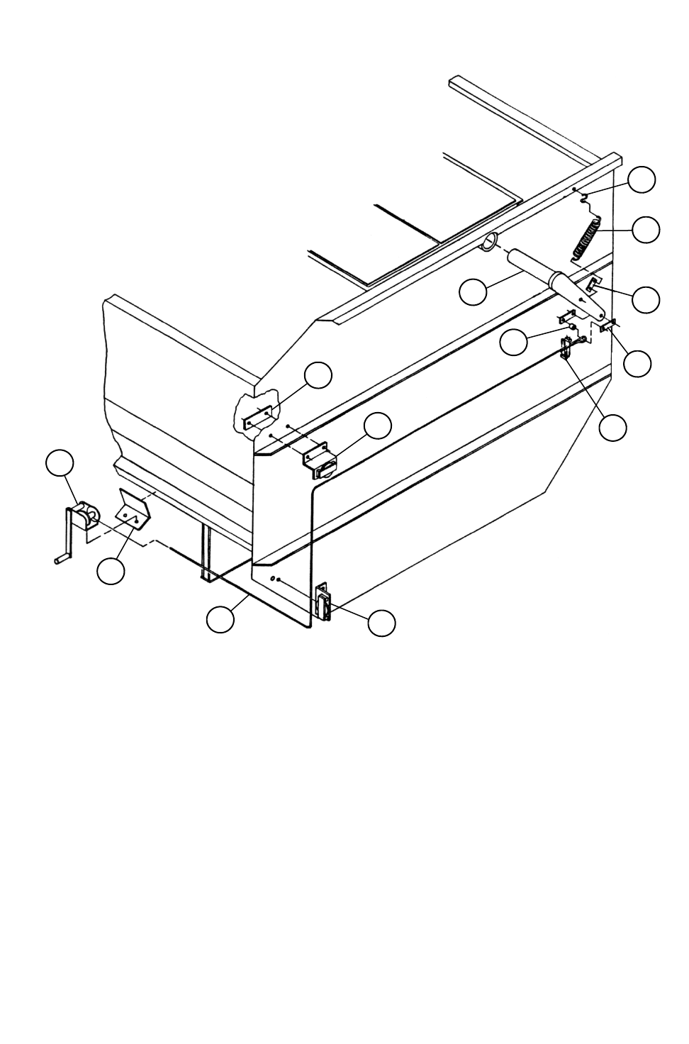
78
524 ROTOR-HAY PROCESSOR (CABLE OPTION)
REF. NO PART NO. DESCRIPTION QTY.
1 150188 CABLE BAR.............................................................................. 2
2 150189 SLEEVE .................................................................................... 1
3 150190 CABLE ...................................................................................... 1
4 412204 CABLE CLAMP, 1/4”................................................................. 2
5 412325 CABLE BRAKE WINCH, 1000LB. ............................................ 1
6 850066 CABLE PULLEY BRACKET WELDMENT................................ 1
7 150186 CABLE WINCH MOUNT PLATE .............................................. 1
8 850090 HAY PAN CABLE ARM WELDMENT....................................... 1
9 850105 CORNER PULLEY BRACKET WELDMENT ............................ 1
10 150228 PULLEY BACKUP PLATE ........................................................ 1
11 410009 PULL SPRING, 1-1/4”OD x 14” x .177” .................................... 1
12 150391 SPRING PULL BAR.................................................................. 1
13 411805 S-HOOK, 5/16”.......................................................................... 1
12
13
11
1
2
8
4
10
6
9
3
7
5
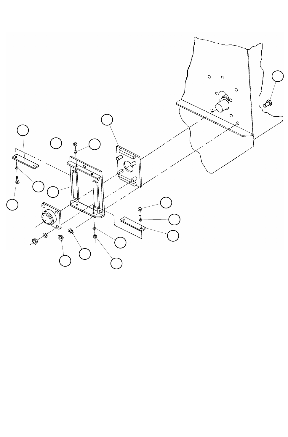
79
524 BOTTOM AUGER FLOAT ASSEMBLY
REF. NO PART NO. DESCRIPTION QTY.
1 850153 BEARING SLIDE PLATE WELDMENT 2-7/16” ................... 1
2 850154 BEARING SLIDE FRAME WELDMENT ............................... 1
3 150418 BEARING SLIDER PLASTIC .................................................. 2
4 405752 HHCS 5/8” X 1 1/2”................................................................... 5
5 405656 HHCS 3/8” X 1 3/4”................................................................... 2
6 405655 HHCS 3/8” X 1 1/2”................................................................... 2
7 402406 FLAT WASHER 3/8” ................................................................ 4
8 402006 LACK WASHER 3/8” ............................................................... 5
9 402010 LOCK WASHER 5/8” ............................................................... 4
10 400210 HEX NUT 5/8”........................................................................... 5
11 400206 HEX NUT 3/8”........................................................................... 4
10
9
8
7
6 5
3
11
2
1
3
4
7
8
11

80
524 FENDERS & MUD FLAPS
REF. NO PART NO. DESCRIPTION QTY.
1 872108 FENDER WELDMENT............................................................. 2
2 183087 MUD FLAP STRAP ..................................................................4
3 370202 FRONT MUD STRAP ............................................................... 2
4 370200 REAR MUD STRAP.................................................................. 2
5 872120 MUD FLAP BRACKET WELDMENT .................................... 2
2
3
1
1
5
2
5
4
