BridgeWave Communications BW64 BridgeWave BW64 & BW64E User Manual pt 2
BridgeWave Communications, Inc. BridgeWave BW64 & BW64E pt 2
UserManual.wiki
>
BridgeWave Communications
>
BW64 User Manual
>
User Manual pt 2
Contents
1.
User Manual pt 1
2.
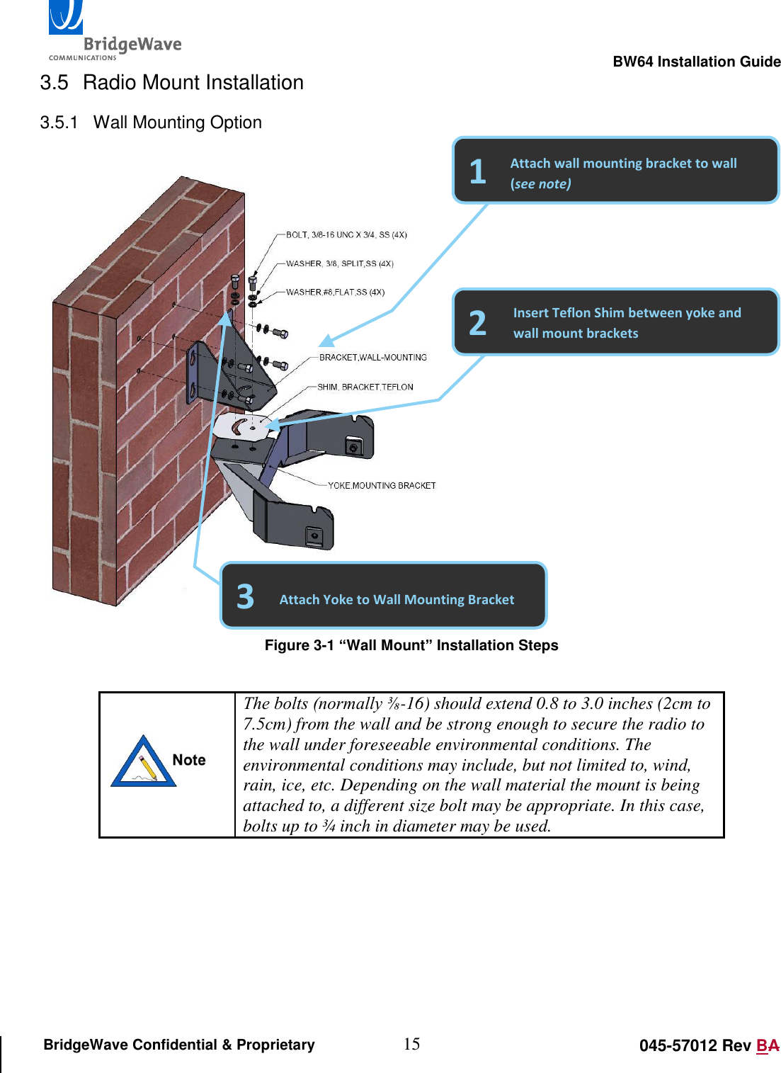
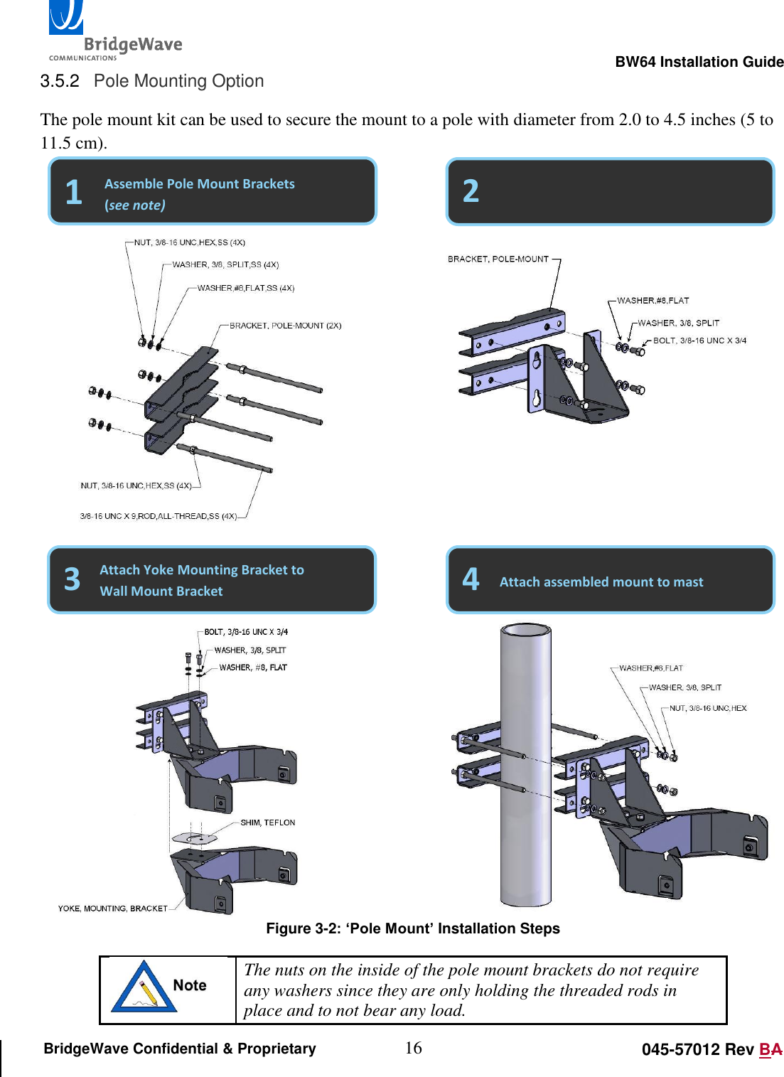
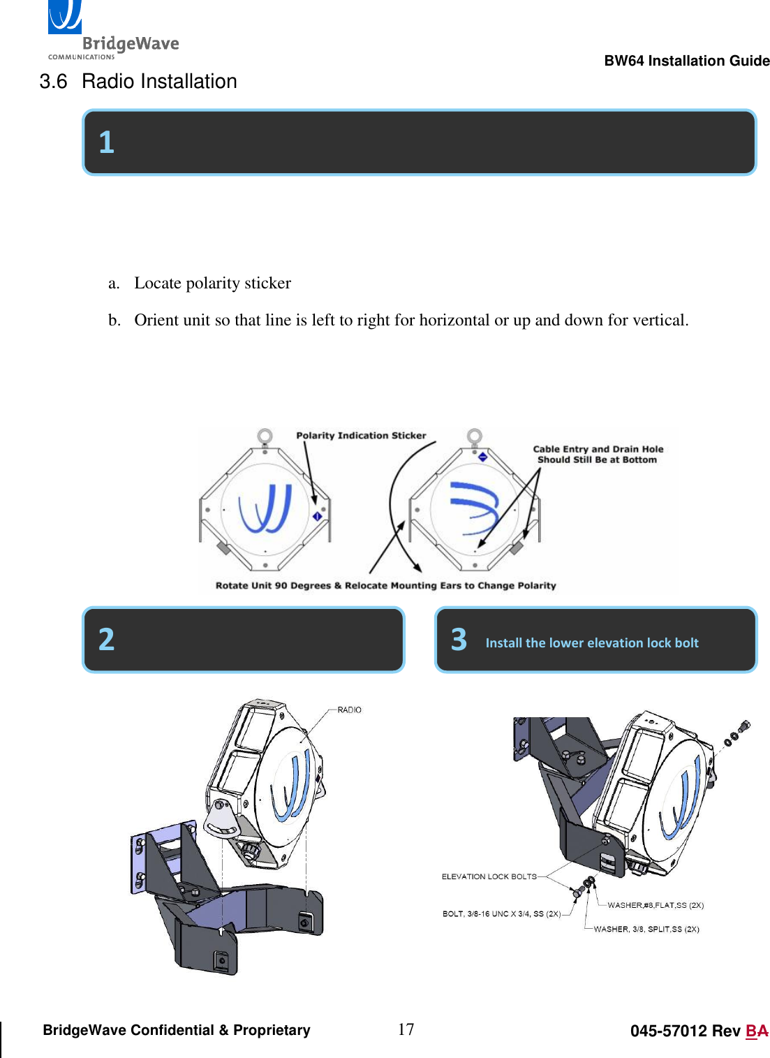
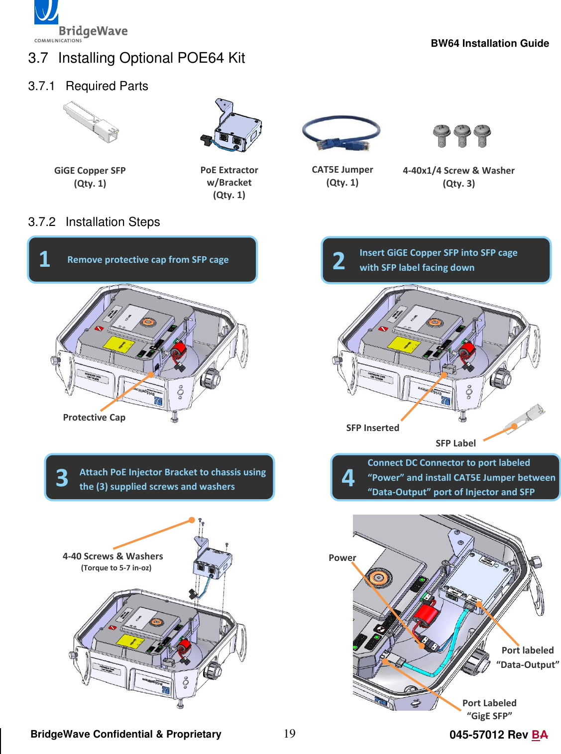
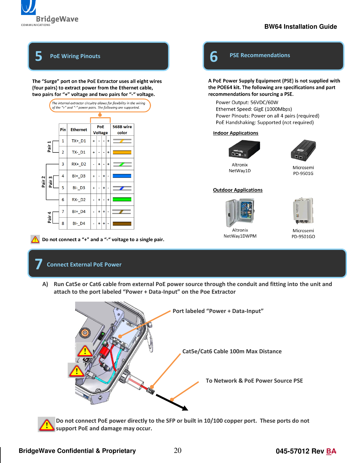
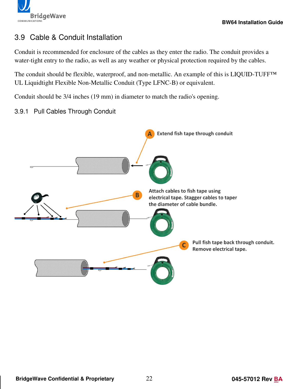
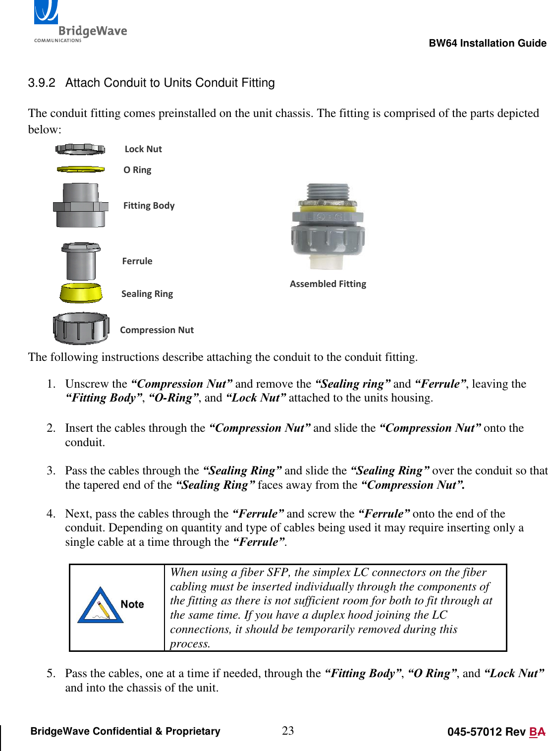
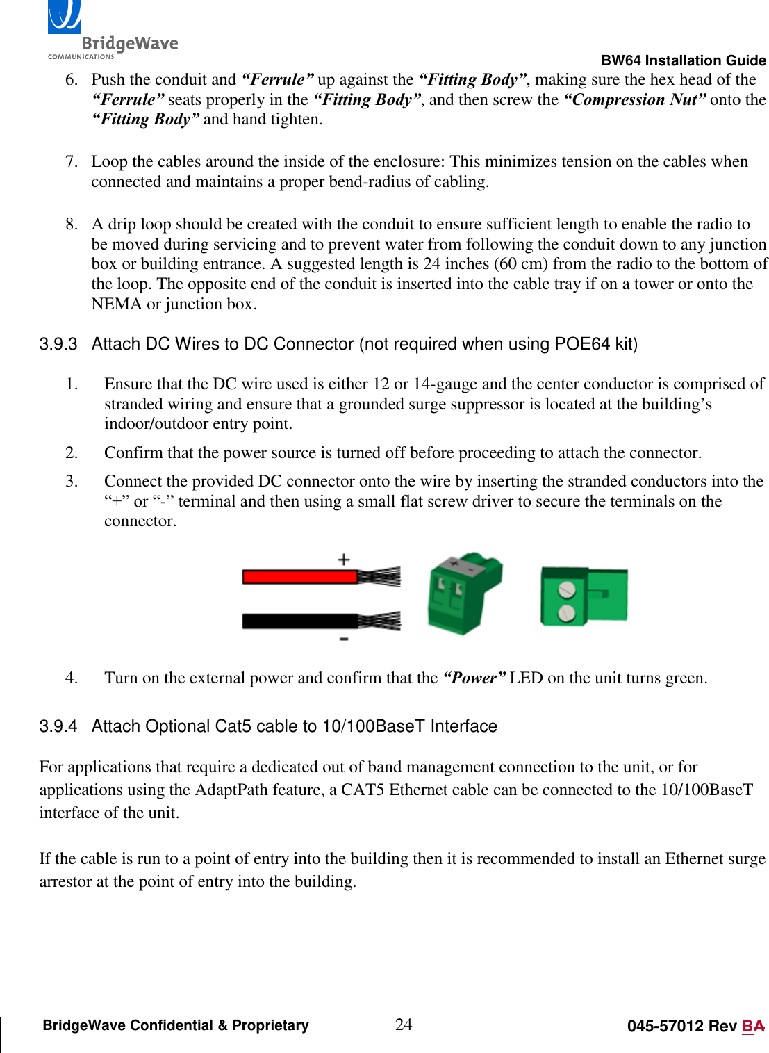
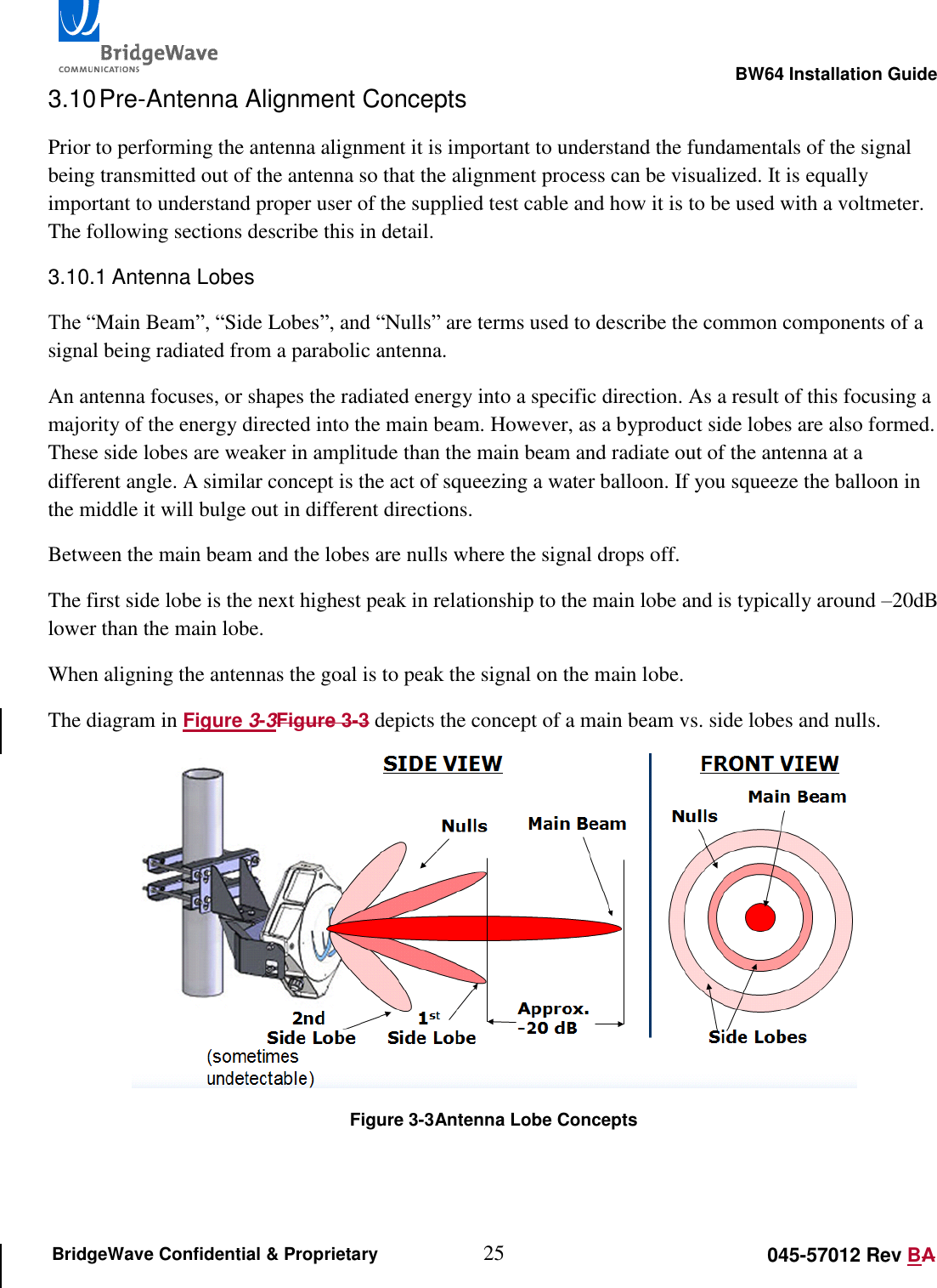
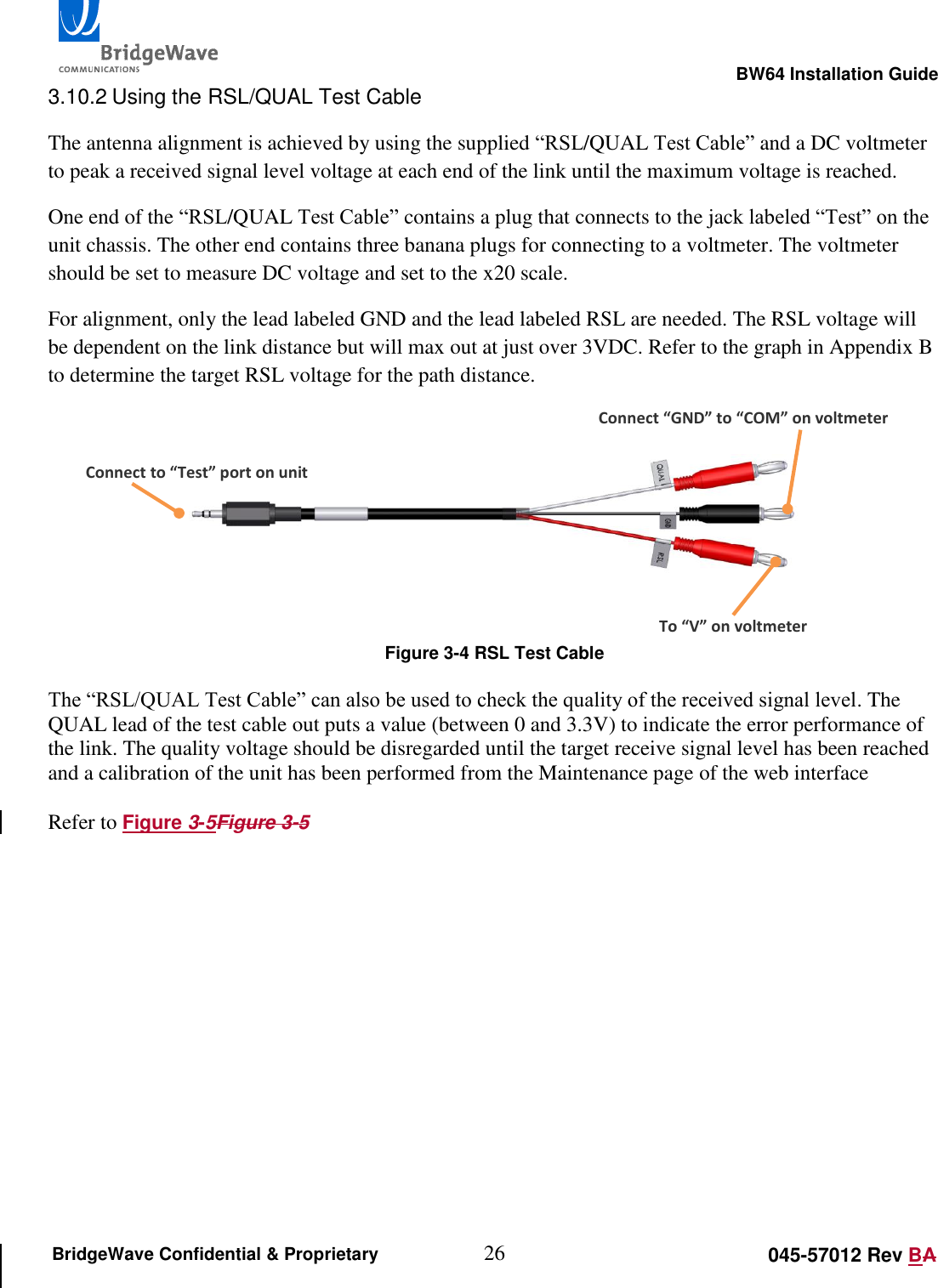
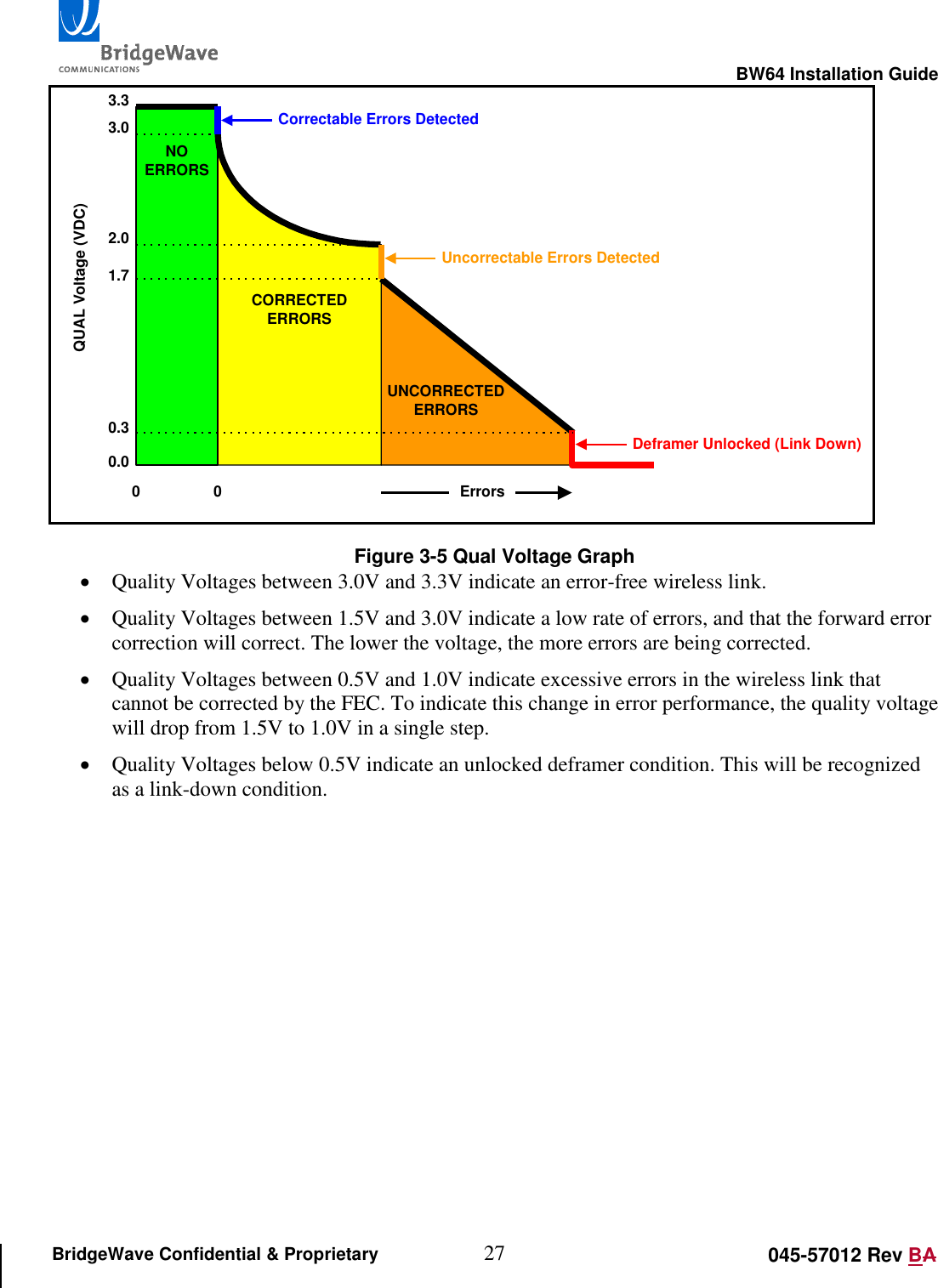
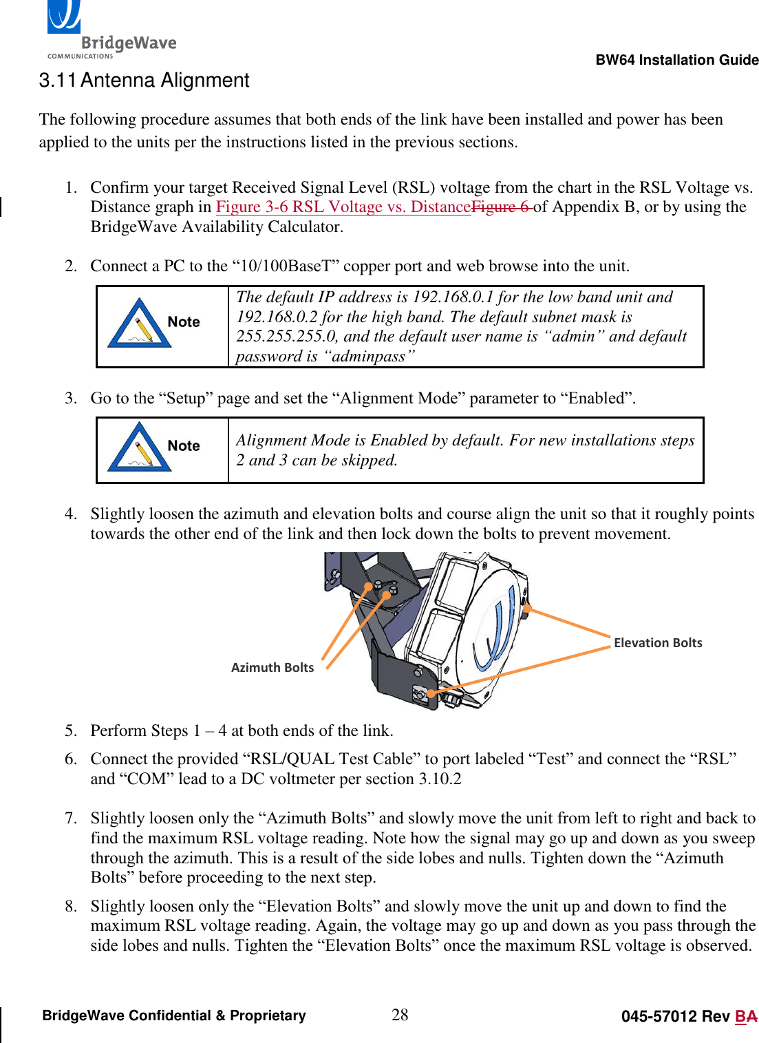
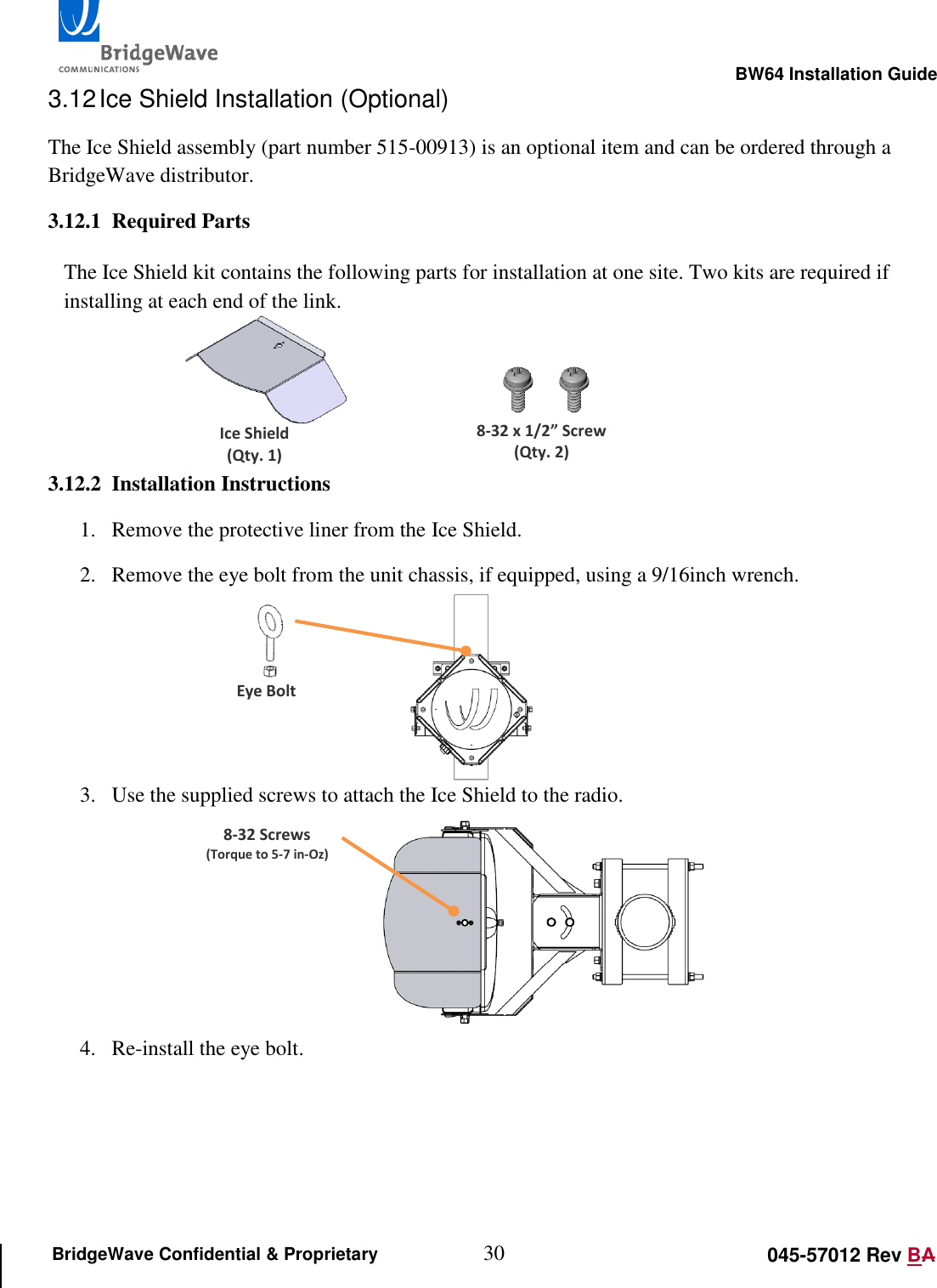
User Manual pt 2
3.
User Manual pt 3
User Manual pt 2
Navigation menu
Upload a User Manual
Namespaces
Wiki Guide
HTML
PDF
Info
Views
User Manual
Discussion / Help
Navigation