Brigade Electronics Plc BACKSENSE Brigade Backsense Radar User Manual
Brigade Electronics Plc Brigade Backsense Radar
User Manual

Brigade Backsense® Installation Guide v1.2
(4555) Page 1
Installation Guide
Backsense®
Radar Obstacle
Detection Systems
Models: BS-8000, BS-7030,
BS-7045, BS-7060
Brigade Backsense® Installation Guide v1.2
(4555) Page 2
Contents Page
1.0 Introduction 3
1.1 System Functionality 3
1.2 Detection Distances 3
2.0 System Components 4
3.0 Hardware Installation 4
3.1 Installation Site 4
3.2 Sensor Mounting 4
3.3 Display Mounting 4
3.4 Cable 5
4.0 Initial System Power Up and Test 5
5.0 Configurable System - BS-8000 5
5.1 Configuration Tool software installation 5
5.1.1 System requirements 6
5.1.2 UI Overview 6
5.1.3 Main Menu 6
5.2 Connecting to the system 6
5.2.1 Com Port 7
5.2.2 Connect Sensor 7
5.3 Detection Zone Setup 7
5.3.1 View Detection Zone 8
5.3.2 Setup Detection Zone 8
5.3.3 Detection Area Length 9
5.3.3.1 Detection Zone Length setup 9
5.3.3.2 Quick Zones Detection Area Length (D.A.L.) 9
5.3.3.3 Detection Zone Width 9
5.3.3.4 Trigger Output Length 10
5.3.3.5 Buzzer Starting Zone 10
5.3.4 Blind zone setup 11
5.3.4.1 Selecting blind zone cells 12
5.3.5 Writing settings to display 12
Appendix I – System Connectivity 15
Appendix II – Configuration Tool software installation 16
Appendix III – Daily Maintenance 20
Appendix IV – Specifications 21
Appendix V - Mounting Dimensions 22
Appendix VI FCC Statement: 23

Brigade Backsense® Installation Guide v1.2
(4555) Page 3
1.0 Introduction
Bigades Baksese FMCW radar systems are designed to detect people and objects in blind spots, significantly
reducing accidents. They detect stationary and moving objects, providing the driver with in-cab visual and audible
warnings – alerting the operator whose attention cannot be focused on all danger areas. Backsense works effectively
in harsh environments and in poor visibility including darkness, smoke and fog.
It is imperative that Brigade Backsense® is fitted and commissioned by competent and trained technicians. The
installer is responsible for the fitness for purpose of the overall system and adheres to relevant regulations and
legislation. Operators of the vehicle to which the Brigade Backsense® system is fitted must be made fully aware of
how to interpret the system so they will not be distracted by or rely completely on it. Distraction can cause accidents.
The system is intended to aid the operator, who must still concentrate on operating the vehicle, obey traffic and
local regulations and continue to use his/her own training, senses and other vehicle aids, such as mirrors, as would
be done if the system were not in place. Nothing removes the responsibility of the operator to operate the vehicle in
a proper and lawful manner.
1.1 System Functionality
The Brigade Backsense® uses Frequency Modulated Continuous Wave (FMCW).
FMCW differs from pulsed radar in that an electromagnetic signal that is continuously transmitted. The frequency of
the signal changes over time, generally in a sweep across a set bandwidth. Backsense® bandwidth is 24.068 –
24.218GHz.
1.2 Detection Distances
The four available systems are as follows:
* - Default settings
Model (Part No.)
Length (m)
Each Zone Length (m)
Width (m)
Minimum Tolerance (m)
BS-7030 (4527)
3.0
0.6
2.5
±0.25
BS-7045 (4528)
4.5
0.9
3.5
±0.25
BS-7060 (4529)
6.0
1.2
4.5
±0.25
BS-8000 (4530)
3.0 – 30.0
*(10.0)
1.0 – 26.0
*(2.0m)
2.0 – 10.0
*(7.0m)
±0.75
BS-7030, 7045 & 7060 have fixed detection length and width divided into five equal detection zones. The buzzer and
trigger output activate in all zones on detection. Stationary objects are detected from the start of the detection area
up to 1.2m of the sensor. Any stationary object will not be detected inside 1.2m – 0.2m of the sensor unless the
object or vehicle moves; detection to alert will take less than 0.2sec. Any object closer than 0.3m will not be
detected.
The BS-8000 uses the same fundamental operation as all the above systems but detection zone, blind zone, trigger
length and buzzer starting zone are all configurable. Refer to section 5.0.

Brigade Backsense® Installation Guide v1.2
(4555) Page 4
x4
2.0 System Components
Sensor Display Extension Cable Fixing Kit
Configurable system: as above and including
Software CD Mini USB Cable
3.0 Hardware Installation
Refer to the vehicle manufacturers bodybuilder guidelines for installation procedures and connectivity in all
applications. Ensure the positive connections are fused at source. System connections are shown in the table below.
Connect red and black to ignition and ground, grey connected to the activating trigger (e.g. reverse) and white is a
ground output trigger which is active under detection (customisable on the BS-8000 system).
System Connections
RED
Ignition +12/24v
BLACK
Ground
GREY
Activation trigger
WHITE
Ground trigger output
3.1 Installation Site
The installation site, for calibration purposes, must be relatively flat without excessive deviation. Flat does not
necessarily mean level; a sloping flat area may be acceptable as long as the vehicle does not lean excessively.
3.2 Sensor Mounting
The sensor should be mounted in the upright position (Brigade logo in normal orientation) avoiding detection of the
ground and any vehicle furniture where possible. This is critical on the non-configurable systems where obstacles
can be ignored in the configurable system.
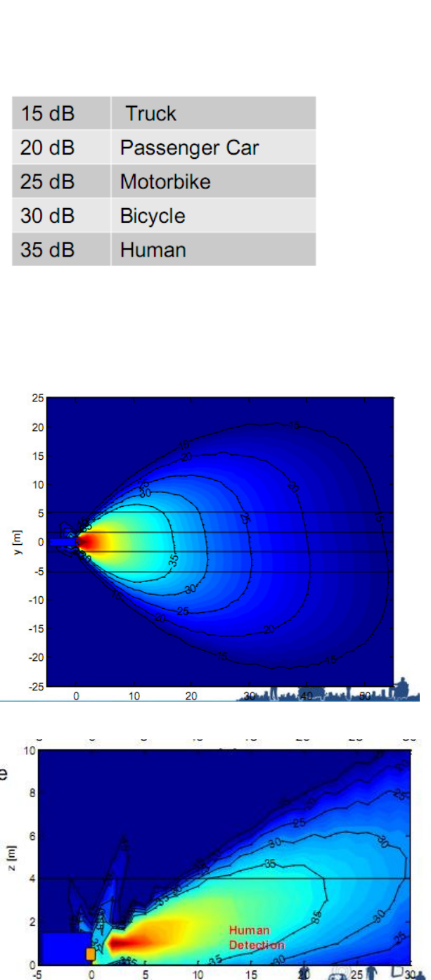
The horizontal angle of the detection zone is 110° ±10° . and the vertical 12°±2°.
[INSERT DIAGRAMS CONTAINING DETECTION PATTERNS]
SYSTEM
SENSOR
DISPLAY
CABLE
SOFTWARE
CONNECTIVITY
BS-7030 (4527)
BS-7XXXS (4542)
BS-7030D (4531)
BS-09DCX (4551)
-
-
BS-7045 (4528)
BS-7XXXS (4542)
BS-7045D (4532)
-
-
BS-7060 (4529)
BS-7XXXS (4542)
BS-7060D (4533)
-
-
BS-8000 (4530)
BS-8000S-S
BS-8000D (4534)
CD (4553)
USB CBL (4554)
Brigade Backsense® Installation Guide v1.2
(4555) Page 5
Horizontal Detection
Vertical detection
3.3 Display
The display should be mounted where the vehicle operator has good visibility in all environments. The display should
be fixed in a suitable location in line with any current legislation/regulations.

Brigade Backsense® Installation Guide v1.2
(4555) Page 6
The base is fixed to the display with a keyway locking method and a machine screw for fixing. An adhesive pad is
included to fix the base to the dashboard, drilling and fixing with screws maybe required in some applications.
The neck is adjustable in all directions up to 30° and is secured with a locking nut. The volume is adjustable from 65-
90dB.
3.4 Cable
Cables should be run in conduit and along suitable cable runs throughout the vehicle. Allow a reasonable radius
when folding excess cabling. Note: a 24mm hole is required to pass the connectors through.
4.0 Initial System Power Up and Test
Once the sensor and display are installed, wired, and connected, power should be applied to test correct system
operation. Upon power up, the display will go through its self-test by illuminating all LEDs and sounding the buzzer
then the green power LED will be the only light illuminated. When reverse is selected, applying power to the
activation cable, the power LED turns red, check the system is operating correctly in an open field with no
obstructions. If all the detection LEDs are lit, check for any obstruction which may be detected by the sensor. If
possible move the sensor so it is not detecting the object(s). If it is not possible to relocate the sensor, then consult
Brigade.
5.0 Configurable System - BS-8000
Section 5.0 – 5.4 covers the setup of the configurable Backsense®, BS-8000.
DESCRIPTION AND LED COLOUR
FLASH FREQUENCY
ALERT FREQUENCY
FUNCTION
ZONE 5
GREEN
CONSTANT
1.5Hz
-
ZONE 4
LIGHT GREEN
CONSTANT
2Hz
-
ZONE 3
YELLOW
CONSTANT
2.5Hz
-
ZONE 2
ORANGE
CONSTANT
3Hz
-
ZONE 1
RED
CONSTANT
CONSTANT
-
STATUS LED
RED
CONSTANT
-
SYSTEM IN STANDBY
STATUS LED
GREEN
CONSTANT
-
SYSTEM ACTIVE
STATUS LED
FLASHING RED
1Hz
-
SYSTEM ERROR. SYSTEM
NOT ACTIVATED
ALL ZONES ON
STATUS FLASHING
-
-
-
1Hz
CONSTANT FOR
5 SECONDS
SYSTEM ERROR. SYSTEM
ACTIVATED
Detection Zones 5 - 1
Status LED
Locking Nut
Adhesive pad
Volume Control

Brigade Backsense® Installation Guide v1.2
(4555) Page 7
5.1 Configuration Tool software installation
The installation files can be found on the CD supplied with the BS-8000 kit (CD-BS8000-00 (4553)). Run the setup file
to install the configuration tool. Refer to Appendix II for installation instruction.
A USB to serial port driver is required to communicate between the PC and display. This is included on the CD and
should be installed before connection can be made.
Once installed connect the display to the PC using the provided USB cable (the display should be powered but does
not need to be activated). To check the COM port number you are using you will need to open Device Manager on
the PC.
Click Windows> Run… . I the dialogue o opeed, tpe devmgmt.msc ad pess ete; this will open the Device
Manager.
Clik Pots COM & LPT ad hek Polifi U“B-to-Serial Co Pot COM## the COM## number in brackets is
the port the display is currently connected to. Refer to section 5.2.1 Com Port Selection
5.1.1 System requirements
The Configuration Tool is designed for Microsoft Window 7 (32-bit) environment and requires USB 2.0 Type-A
connector. In order to connect LED display, a USB cable (type-A (Male) to Mini-B (Male)) should be used. This is
supplied with the BS-8000 kit.

Brigade Backsense® Installation Guide v1.2
(4555) Page 8
5.1.2 User Interface Overview
This application provides multiple sub-windows. The users can manipulate in different windows view or change the
configuration. The application outline is shown below.
Menu (A) opens different windows to setup the corresponding function; Detection Zone, Blind Zone & Buzzer
Starting Zone etc.
There are two view windows (B); one is for Detection Zone, another is for Blind Zone. The view windows provide the
visual picture in the corresponding setup. Most of the configuration and the information will be shown in the view
window. Each view window has a related configuration window (C). User can set the desired configuration by the
window. The detail will be depicted in later chapter. Status bar (D) shows the status including tip information,
connection state etc.
5.1.3 Main Menu
The Main menu includes four options; System, View, Setup and About.
System is used to control the connection between application and system, reading and writing the configuration to
and from the system, loading/saving the configuration from/to file and Close active window or Exit the program.
View opens the Detection Zone and Blind Zone windows.
Setup opens the configuration windows for the Detection Zone and Blind Zone.
About provides version information for the Configuration Tool.

Brigade Backsense® Installation Guide v1.2
(4555) Page 9
5.2 Connecting to the system
Connect the display to the PC with the Mini USB cable provided in the BS-8000 (4553) kit.
5.2.1 Com Port Selection
Before the tool connects to the display, the correct com port must be selected. Section 5.1 describes how to find the
correct port number.
Clik “ste> Co Pot. This will open the Com Port Setup window (This may take a several seconds whilst the PC
heks aailale o pots. “elet the o pot euied fo the dop do list ad lik OK.
Com Port setup needs to be run every time the configuration tool is opened or you will get the error message
shown.
5.2.2 Connect Sensor
Clik “ste> Coet Sensor. Oe oeted, the “tatus Ba ill displa Coeted at the otto ight of the
main window.
Brigade Backsense® Installation Guide v1.2
(4555) Page 10
5.3 Detection Zone Setup
Note: when setting up the detection zone and blind zones all dimensions are approximate.
5.3.1 View Detection Zone
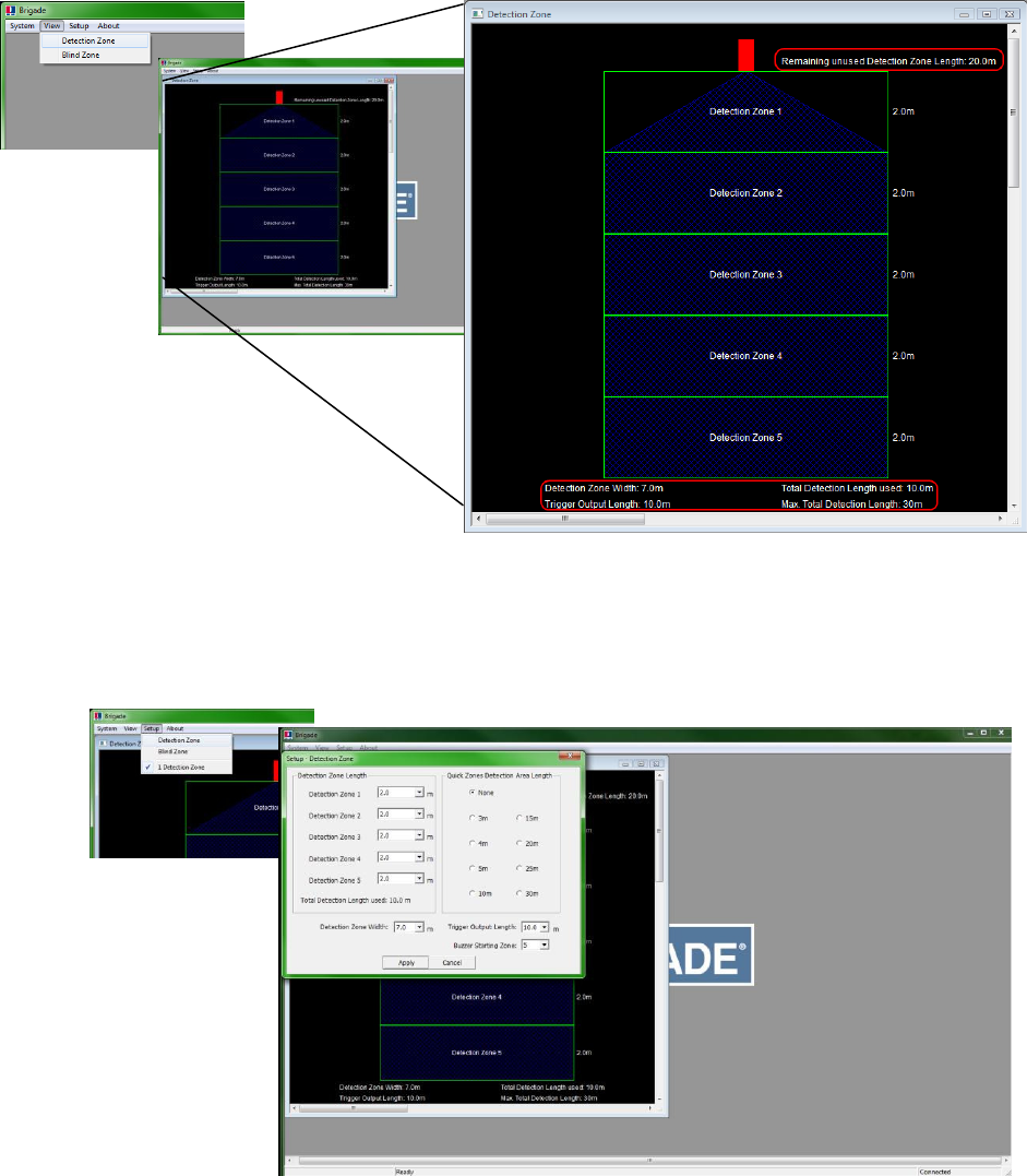
Clikig Vie> Detetio )oe ill ope the Detetio )oe ido. This ido displas the uet detetio
length and width divided into zones. The default configuration for a BS-8000 is 10m x 7m with 5 zones equally
divided into 2m as shown below.
5.3.2 Setup Detection Zone
Clikig “etup> Detetio )oe ill ope the “etup – Detetio )oe ido. This is used to configure Detection
Zone Length, Detection Zone Width, Trigger Output Length and Buzzer Starting Zone.
Brigade Backsense® Installation Guide v1.2
(4555) Page 11
5.3.3 Detection Area Length
The detection area length can be set in two ways, Detection Zone Length or Quick Zones Detection Area Length.
5.3.3.1 Detection Zone Length Setup
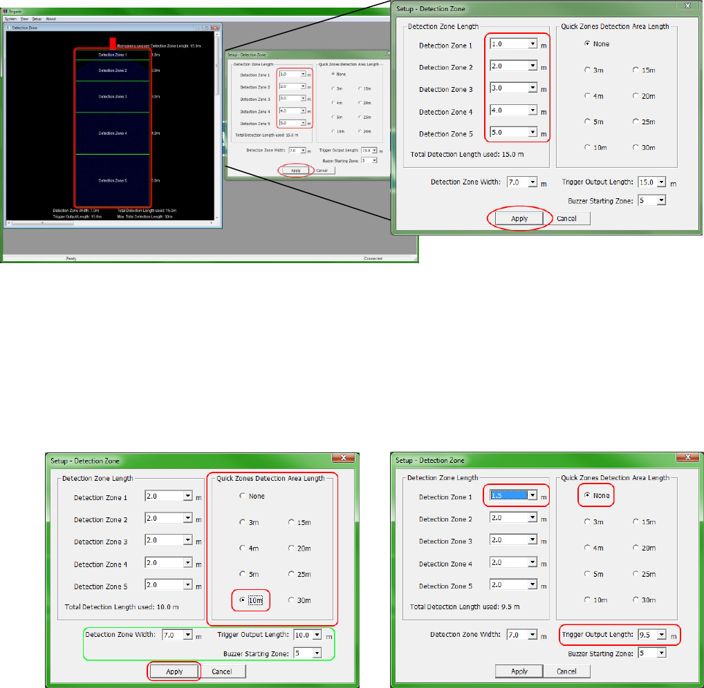
This is used to setup each of the five zones individually. Each zone has a range from 1.0m to 26.0m. The combined
total length will not exceed 30m. The image below shows zones setup from 1.0m to 5.0m giving a total of 15.0m
detection. Clicking Apply after selection will change the preview shape
5.3.3.2 Quick Zones Detection Area Length
Thee ae eight Quik )oes, these ae peset zoes ad a e seleted likig the appopiate hek box next
to the desired distance. Using this option will set the total length and create five equal zones. This does not affect
the width, trigger output length or buzzer starting zone, these must be setup manually. If one of the detection zones
length is changed, the Quick Zones Detection Area Length ill etu to Noe.
Note: the trigger output length will automatically reduce if the total detection length has been shortened.

Brigade Backsense® Installation Guide v1.2
(4555) Page 12
5.3.3.3 Detection Zone Width
Detection zone width ranges from 2.0m to 10.0m. This will set the overall width of the detection to suit the
application as required. For example, the detection width would generally be set to approximately the same width as
the vehicle. “elet the euied detetio zoe idth fo the dop do o ad lik Appl.
5.3.3.4 Trigger Output Length
The trigger output length is set at the point where you want the trigger output to start. For example: below shows a
3m detection length with the Trigger Output Length set at 2.0m (highlighted). The LED display will illuminate and
beep at the start of detection (3.0m) but the trigger output would not activate until the detected object moves
within 2.0m of the sensor. Select the required trigger output length from the drop down box and lik Appl.
5.3.3.5 Buzzer Starting Zone
The buzze statig zoe is set at the poit hee ou at the displas uzze to start sounding. The example
below shows the Detection Zone Length at 10.0m with the Buzzer Starting Zone being set at 3.0m. This means the
display will show illuminated warnings only until the detected object is within 3.0m of the sensor, at this point the
buzzer will sound. “elet the euied uzze statig zoe fo the dop do o ad lik Appl.
Brigade Backsense® Installation Guide v1.2
(4555) Page 13
5.3.4 Blind zone setup
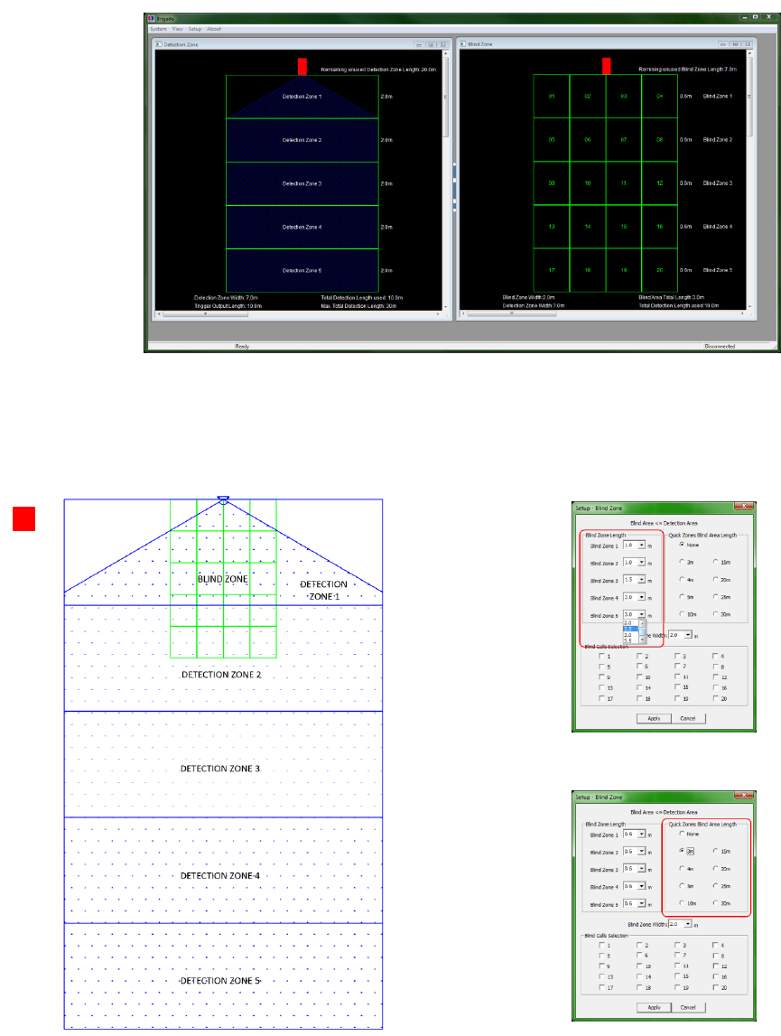
With the BS-8000, blind zones inside the detection area can be set up to ignore areas inside the detection pattern.
These can be set at different sizes and selected individually to accommodate varied applications.
The image below (a) shows the Detection Zone view and Blind Zone view side by side in the configuration tool. The
second image (b) shows the actual relationship between the two images displayed in the tool.
In the image below the blind zone area is set to a 3.0m x 2.0m box in front of the sensor. This box, no matter how
big, is divided into 5 zones, each zone containing 4 cells. The zones can vary in length if manual configuration is
preferred or required (c). If the Quik )oes Blid Aea Legth optio is used (d) then all zones will be equally split
over the full blind zone area.
(a)
(b)
(c)
(d)

Brigade Backsense® Installation Guide v1.2
(4555) Page 14
5.3.4.1 Selecting blind zone cells
Once the blind zone area has been decided, each cell can be selected individually to remove the area from the
detection zone. Any object in the red selected area will now be ignored if detected.
Each cell is selected in the setup window using the tick boxes shown. The tick boxes directly correspond to the cells
sho i the Blid )oe ido. Oe seleted, lik Appl ad the ell text will turn red, indicating the area has
been selected. To remove a selected cell, simply un-tick the corresponding box and click Apply.
Ensure each blind zone is thoroughly checked for correct operation with the vehicle stationary and in motion.
5.3.5 Writing settings to display
Once the configuration is complete, the settings are then uploaded to the display.
Clik “ste> Wite Cof. , this ill upload the ofiguatio to the displa. Done-Note: There is no easily
recognisable indication to show download progress to the system memory. The oeted io o the ight of the
status a oetail hages to Witig… to idiate the upload is i pogess, this is ot alas isile.

Brigade Backsense® Installation Guide v1.2
(4555) Page 15
Appendix I – System Connectivity
Brigade Backsense® Installation Guide v1.2
(4555) Page 16
Appendix II – Configuration Tool software installation
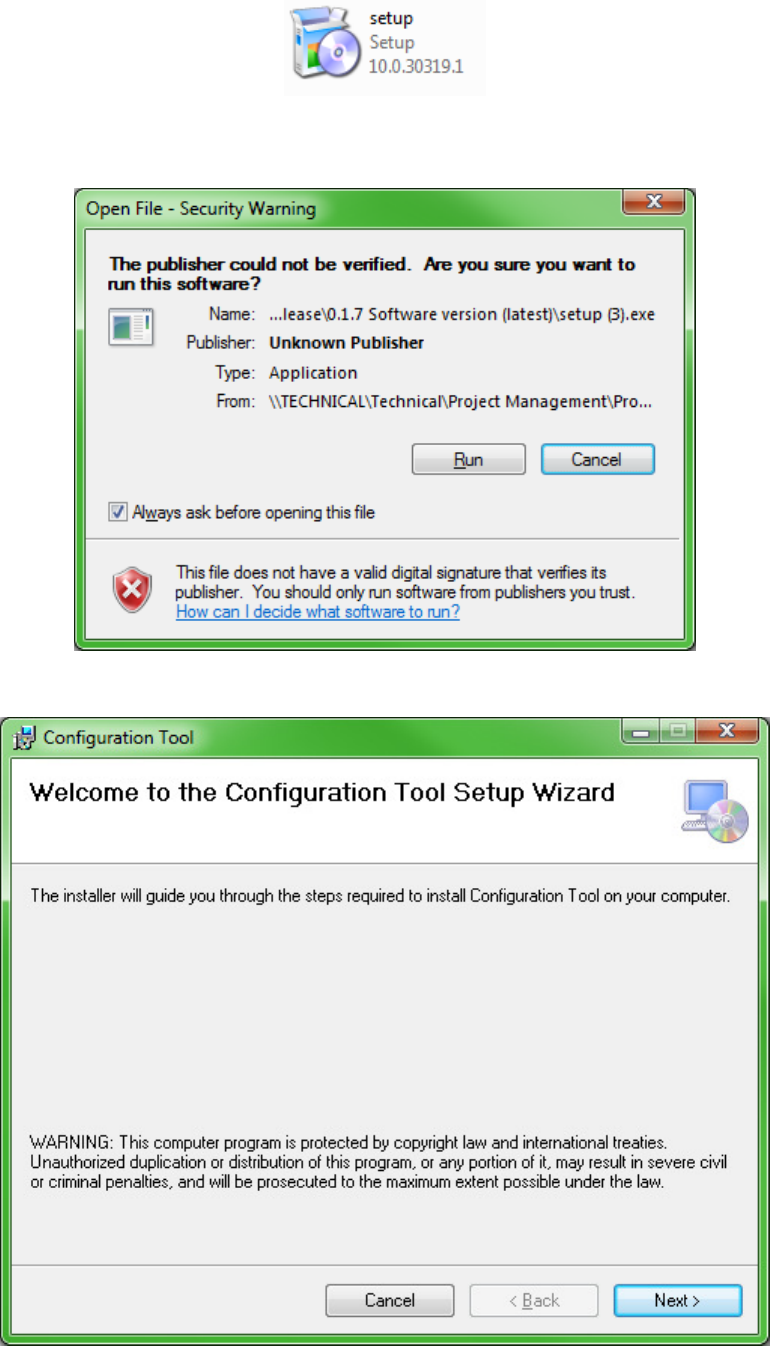
Doule lik setup.
I soe ases ou a hae a sigatue aig. Clik ‘u to otiue ith the istallatio. If usue please efe
to you IT department.
Clik Net >.

Brigade Backsense® Installation Guide v1.2
(4555) Page 17
Check the tick-box to create a desktop io ad lik Net >.
Cofi the istallatio folde loatio is oet ad lik Net >. The default location is shown below.

Brigade Backsense® Installation Guide v1.2
(4555) Page 18
Cofi istallatio likig Net >.
The installation progress will be shown as displayed below.
Brigade Backsense® Installation Guide v1.2
(4555) Page 19
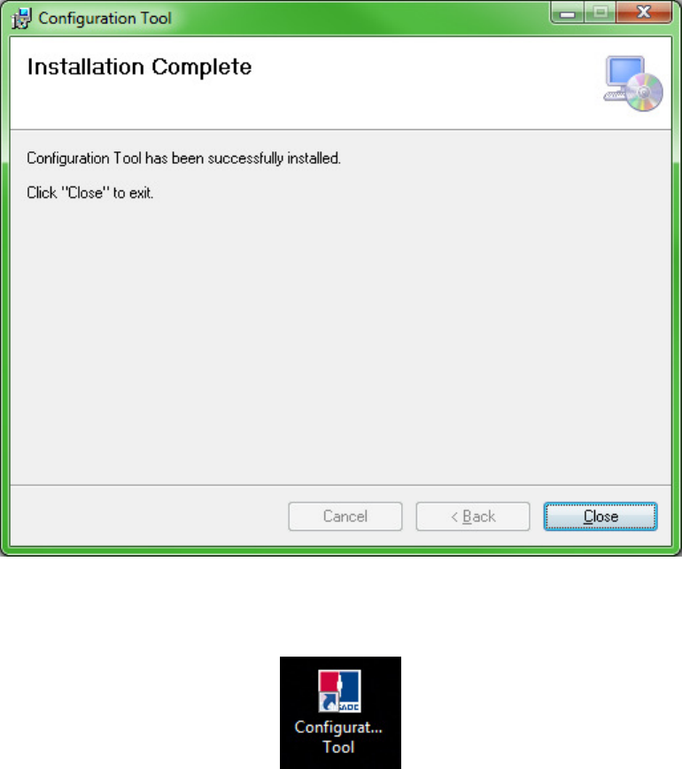
Oe the istallatio is oplete lik Close.
Desktop Icon shown below.
Brigade Backsense® Installation Guide v1.2
(4555) Page 20
Appendix III – Daily Maintenance
Detach this page and place with daily operator maintenance procedures
Safety Message to Operators of Vehicles with Backsese™ Systes
1. The Baksese™ sste is iteded as a Ojet Detetio “ste ad should ot e elied upo as ou fist lie of
defence for the safe operation of the vehicle. It should be used in conjunction with established safety programs and
procedures to augment the safe operation of the vehicle, ground personnel, and adjacent property. Should the system
become inoperative, it could jeopardize the safety or lives of those who depend on the system for safety.
2. Testing and inspection of the system in accordance with these instructions and record of the results should be listed on
the daily maintenance report. The units installed on operating vehicles must be tested each day prior to the vehicle's
operation. Results of this test must be recorded in the maintenance log.
3. People operating this equipment MUST check for proper operation at the beginning of every shift or safety inspection
period.
4. People's lives depend on the proper installation of this product in conformance with these instructions. It is necessary
to read, understand and follow all instructions shipped with the product.
5. Failure to follow all safety precautions and instructions may result in property damage, serious injury, or death.
6. The Baksese™ Ojet Detetio “ste is iteded fo oeial use. Pope istallatio of a ak-up aid requires a
good understanding of truck electrical systems and procedures, along with proficiency in the installation.
7. Store these instructions in a safe place and refer to them when maintaining and/or reinstalling the product.
Testing and Maintenance
IMPORTANT: A walk around test shall be performed regularly to verify proper function of the system and to familiarize the
operator with the zone of detection. More frequent inspections should be performed when:
The vehicle is operating in a particularly dirty or harsh environment.
The operator has reason to suspect the system has been damaged.
This test should be performed with two people, one who remains in the cab (the operator), and one who walks through the
sensor field to the rear of the vehicle (the assistant).
1. Clean the black sensor surface of any accumulation of dirt, mud, snow, ice, or debris.
2. Visually inspect the attached wiring and cable and verify that they are properly secured, not chafing or dangling free
where they could become snagged and damaged. Inspect the Radar Sensor and Operator Display Module and verify
that they are securely attached to the vehicle.
3. Start the vehicle, set the park brakes, and place the vehicle in reverse.
4. Veif the gee POWE‘ light is illuiated o the i-cab display.
5. The area to the rear of the vehicle should be clear of obstacles for a distance of 8 meters. If the display shows any
indicator other than the green light then there are objects to the rear of the vehicle that will interfere with the test.
Move the vehicle to a clear area and proceed.
6. The assistant should move to the rear of the vehicle and to the side so that he is in sight of the operator's mirrors. He
should egi ½ ete 20 to the ea of the eaost pat of the ehile. As the assistat alks toads the etelie
of the vehicle parallel to the rear, the external backup alarm will activate, signifying the sensor has detected him. Upon
hearing the backup alarm the operator should verify that all of the display LED‟s are lit and the audible alarm is quickly
pulsing. Note: If an external backup alarm is not connected, the operator will notice a detection only by the display
LED‟s and buzzer operation and communicate the detection or lack of detection to the assistant as the assistant moves
through the area to the rear of the vehicle.
7. The assistant should continue walking through the area at the rear of the vehicle noting the area that detection occurs.
8. Now walk from the centre of the rear of the vehicle straight back, away from the vehicle. When the alarm quits
sounding the detection limit has been reached.
9. Move halfway back and remain still fo a fe seods, the ala should otiue to soud, deostatig the sstes
ability to detect a still object.
10. The assistant should walk the complete rear of the vehicle noting the detection edges of the entire coverage area.
11. After the test the assistant needs to communicate to the operator the details on where detection started and stopped
to the rear of the vehicle.
Brigade Backsense® Installation Guide v1.2
(4555) Page 21
Appendix IV - Specifications
SENSOR SPECIFICATIONS (Typical)
Model: BS-7030S, BS7045S, BS-7060S and BS-8000S
Transmitter: Frequency Modulation Continuous saw tooth Waveform - FMCW
Connector: Deutsch DT06-4S-CE06
Sealing: Encapsulated to protect from dust and moisture to IP69K.
Housing Material: Black Textured ASA+PC
Dimensions: 220 x 130 x 50mm
Weight: 700gm (including pigtail cable)
Operating Temperature: -40°C to +85° C
Vibration: 20G
Shock: 100G all three axes
Mounting: Four (5.2mm) diameter holes on 198mm horizontal centres, and 40mm vertical centres. Unit is
supplied with M5x30mm screws and M5 polymer locknuts for mounting purposes. Recommended
torque is 50 inch-lbs.
DISPLAY SPECIFICATIONS (Typical)
Model: BS-7030D, BS7045D, BS-7060D and BS-8000D
Housing Material: ABS777E
Dimensions: 100 x 70 x 25mm
Weight: 300gm (including pigtail cable)
Mounting: Supplied with 3M VHB tape fixed to base. Screw may be required to fix base in some applications.
ELECTRICAL SPECIFICATIONS
Input Voltage: 9-32VDC, over voltage protected to 36V
Input current: <0.4 amp maximum
Polarity: Negative ground, Polarity protected to 150V
Power Connection: Available through display connector
Activation Input: 0-32v (Active above 9vdc, inactive below 7vdc)
Trigger Output: Active State: switched to ground, over current protected to 1 amp sink maximum.
Inactive State: High impedance
OPERATING CHARACTERISTICS
Maximum Range: 30m
Fixed Ranges: 6.0m, 4.5m, 3.0m
Programmable Ranges: 3-30m
Warning Ranges: 5 zones divided into programmed range
Minimum Resolution: 1.2m
COMMUNICATION
Physical Layer: CAN 2.0B, 250 KB/s
Protocol Layer: SAE J1939 Extended
Data Update Rate: 70 ms

Brigade Backsense® Installation Guide v1.2
(4555) Page 22
Appendix V – Mounting Dimensions
Brigade Backsense® Installation Guide v1.2
(4555) Page 23
Appendix VI FCC Statement:
Federal Communication Commission Interference Statement
This equipment has been tested and found to comply with the limits for a Class B digital device, pursuant to Part 15 of
the FCC Rules. These limits are designed to provide reasonable protection against harmful interference in a
residential installation. This equipment generates, uses and can radiate radio frequency energy and, if not installed
and used in accordance with the instructions, may cause harmful interference to radio communications. However,
there is no guarantee that interference will not occur in a particular installation. If this equipment does cause harmful
interference to radio or television reception, which can be determined by turning the equipment off and on, the user is
encouraged to try to correct the interference by one of the following measures:
● Reorient or relocate the receiving antenna.
● Increase the separation between the equipment and receiver.
● Connect the equipment into an outlet on a circuit different from that to which the receiver is connected.
● Consult the dealer or an experienced radio/TV technician for help.
FCC Caution: Any changes or modifications not expressly approved by the party
responsible for compliance could void the user’s authority to operate this equipment.
This device complies with Part 15 of the FCC Rules. Operation is subject to the following two conditions: (1) This device may not
cause harmful interference, and (2) this device must accept any interference received, including interference that may cause
undesired operation.