Briggs & Stratton 01935 User Manual GENERATOR Manuals And Guides L0404382
BRIGGS&STRATTON Generator Manual L0404382 BRIGGS&STRATTON Generator Owner's Manual, BRIGGS&STRATTON Generator installation guides
User Manual: Briggs & Stratton 01935 01935 BRIGGS & STRATTON GENERATOR - Manuals and Guides View the owners manual for your BRIGGS & STRATTON GENERATOR #01935. Home:Tool Parts:Briggs&Stratton Parts:Briggs&Stratton GENERATOR Manual
Open the PDF directly: View PDF ![]() .
.
Page Count: 40
Husqvarna
01935 1365GN
Owner's Manual /Manual del Propietario
_Read this manual carefully and become familiar with your generator.
Know the applications, the limitations and any hazards involved.
_Lea este manual de manera cuidadosa y familiaricese con su generador.
Conozca sus usos, sus limitaciones y cualquier peligro relacionado con el mismo.
0 3 Part Number 531 30 00-69
Safety Rules
TABLE OF CONTENTS
Safety Rules.................................. 2-4
Know Your Generator ........................... 5
Assembly.................................... 6-7
Operation .................................. 8-13
Maintenance.................................. 14
Storage...................................... 15
Notes ....................................... 16
Troubleshooting ............................... 17
Schematic/Wiring Diagram .................... 18-19
Replacement Parts........................... 20-24
Warranty .................................... 25
EQUIPMENT
DESCRIPTION
_Read this manual carefully and become familiar
with your generator. Know the applications, the
limitations and any hazards involved.
This generator is an engine-driven, revolving field,
alternating current (AC) generator. It was designed to
supply electrical power for operating compatible electrical
lighting,appliances,tools and motor loads.Thegenerator's
revolving field is driven at about 3,600 rpm by a single-
cylinder engine.
CAUTION! DO NOT exceed the generator's
wattage/amperage capacity.See"Don't Overload
Generator" on page 13.
Every effort has been made to ensure that informationin
this manual is accurate and current. However, we reserve
the right to change,alter or otherwise improvethe product
and this document at any time without prior notice.
The Emission Control System for this generator is
warranted for standards set by the Environmental
Protection Agency.For warranty information refer to the
engine owner's manual.
the State of California a spark arrester is required by law
Section 4442 of the California Public ResourcesCode).
)ther states may havesimilar laws.Federal lawsapply on
Federallands.Themuffler is equipped with a spark arrester:
t must be maintained ineffective working order.
Replacementspark arresters may be obtained by calling
1-877-224-0458.
SAFETY RULES
Ahis is the safety alert symbol. It is used to
alert you to potential personal injury hazards.
Obey all safety messages that follow this
symbol to avoid possible injury or death.
The safety alert symbol (_.) is used with a signal word
(DANGER, CAUTION,WARNING), a pictorial and/or a
safety messageto alert you to hazards.DANGER indicates
a hazard which, if not avoided,will result in death or
serious injury.WARNING indicatesa hazard which, if not
avoided,could result in death or serious injury.
CAUTION indicatesa hazard which, if not avoided,might
result in minor or moderate injury.CAUTION, when used
without the alert symbol, indicatesa situation that could
result in equipment damage.Follow safety messagesto
avoid or reduce the risk of injury or death.
WARNING
The engine exhaust from this product contains I
chemicals known to the State of California to cause
cancer, b rth defects, or other reproduct ve harm.
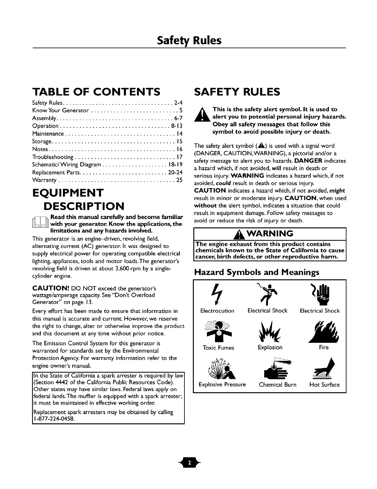
Hazard Symbols and Meanings
Electrocution Electrical Shock Electrical Shock
Toxic Fumes
Explosive Pressure
Explosion Fire
Chemical Burn Hot Surface
Safety Rules
DANGER
Operate generator ONLY outdoors.
Keep at least 2 feet of clearance on all sides of generator for
adequate ventilation.
DO NOT operategenerator insideanybuildingor enclosure,
includingthe generator compartment of a recreationalvehicle(RV).
DANGER
National Electric Code requires generator to be properly
grounded to an approved earth ground. Call an electrician for
local grounding requirements.
DANGER
When usinggenerator for backup power, notify utility
company. Use approved transfer equipment to isolate
generator from electric utility.
Use a ground fault circuit interrupter (GFCi) in anydamp or
highly conductive area,such as metal decking or steel work.
DO NOT touch bare wires or receptacles.
DO NOT use generator with electrical cords which are worn
frayed, bare or otherwise damaged.
DO NOT operate generator in the rain or other forms of
precipitation.
DO NOT handle generator or electrical cords while standing
inwater, while barefoot, or while hands or feet are wet.
DO NOT allow unqualified persons or children to operate or
service generator.
IKWARNING
This generator does not meet U. S.Coast Guard Regulation
33CFR-183 and should not be used on marine applications.
Failure to use the appropriate U. S. Coast Guard approved
generator could result in bodily injuryand/or property
damage.
DANGER
DO NOT allow any open flame, spark, heat, or lit cigarette
during and for several minutes after charging a battery.
Wear protective goggles,rubber apron, and rubber gloves.
WARNING
WHEN ADDING FUEL:
Turn generator OFF and let it cool at least 2 minutes before
removing gas cap. Loosen cap slowly to relieve pressure in tank_
Fill fuel tank outdoors.
DO NOT overfill tank.Allow space for fuel expansion.
Keep fuel away from sparks, open flames, pilot lights, heat, and
other ignition sources.
DO NOT light a cigarette or smoke.
eVHEN OPERATING EQUIPMENT:
DO NOT tip engine or equipment at angle which causes fuel
to spill.
This generator is not for use in mobile equipment or marine
applications.
'HEN TRANSPORTING OR REPAIRING EQUIPMENT:
Transportlrepair with fuel tank EMPTY or with fuel shutoff
valve in the OFF position.
Disconnect spark plug wire.
eVHEN STORING FUEL OR EQUIPMENT WITH FUEL
IN TANK:
Store away from furnaces, stoves, water heaters, clothes
dryers or other appliances that have pilot light or other
ignition source because they can ignite fuel vapors.
Safety Rules
WARNING
;ENERATOR
Disconnect the spark plug wire from the spark plug and place
the wire where it cannot contact spark plug.
, WARNING
DO NOT touch hot surfaces.
Allow equipment to cool before touching.
CAUTION
DO NOT tamper with governed speed.Generator supplies
correct rated frequency and voltage when running at governed
speed.
DO NOT modify generator in any way.
CAUTION
See"Don't Overload Generator" on page 13.
Start generator and let engine stabilize before connecting
electrical loads.
Connect electrical loads in OFF position, then turn ON for
operation.
Turn electrical loads OFF and disconnect from generator
before stopping generator.
CAUTION
Use generator only for intended uses.
tf you have questions about intended use,ask your Husqvarna
dealer or contact customer service at 1-877-224-0458.
Operate generator only on level surfaces.
DO NOT expose generator to excessive moisture, dust, dirt,
or corrosive vapors.
DO NOT insert any objects through cooling slots.
tf connected devices overheat, turn them off and disconnect
them from generatoc
Shut off generator if.'
-electrical output is lost;
-equipment sparks,smokes, or emits flames;
-unit vibrates excessively.
Features and Controls
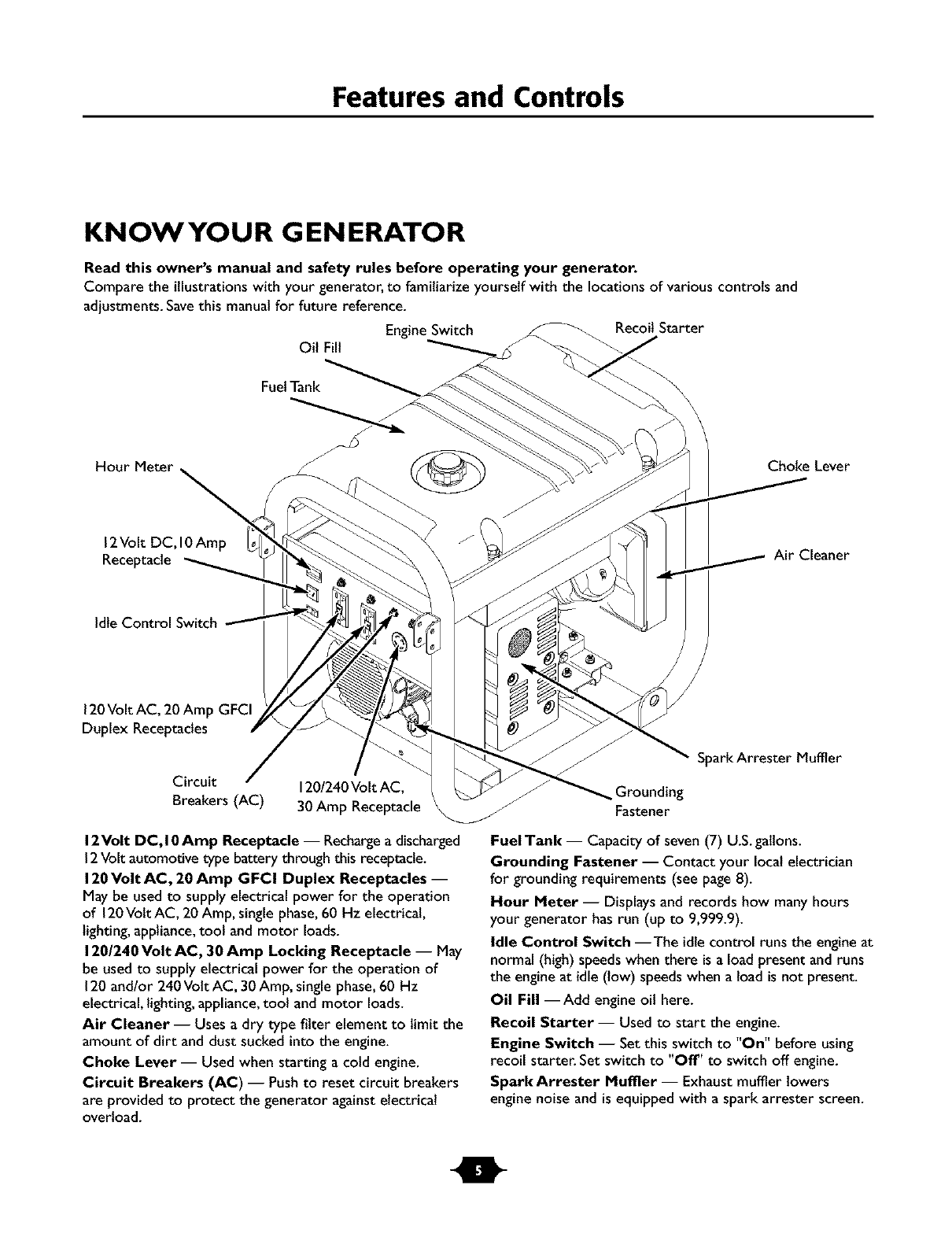
KNOWYOUR GENERATOR
Read this owner's manual and safety rules before operating your generator.
Compare the illustrations with your generator, to familiarize yourself with the locations of various controls and
adjustments. Save this manual for future reference.
Engine Switch Recoil Starter
OilFill
FuelTank
Choke Lever
12Volt DC,10Amp
Receptacle Air Cleaner
Idte Control Switch
120Volt AC, 20 Amp GFCI
Duplex Receptacles
Circuit
Breakers (AC) 120/240Volt AC,
30Amp Receptacle
Spark Arrester Muffler
12Volt DC, I0 Amp Receptacle -- Rechargea discharged
12Volt automotive type battery through this receptacle.
120Volt AC, 20 Amp GFCI Duplex Receptacles --
May be usedto supply electrical power for the operation
of 120Volt AC, 20 Amp, single phase,60 Hz electrical,
lighting,appliance,tool and motor loads.
120/240 Volt AC, 30 Amp Locking Receptacle -- May
be usedto supply electrical power for the operation of
120and/or 240Vott AC, 30Amp, single phase,60 Hz
electrical, lighting,appliance,tool and motor loads.
Air Cleaner -- Uses a dry type filter element to limit the
amount of dirt and dust sucked into the engine.
Choke Lever -- Used when starting a cold engine.
Circuit Breakers (AC) -- Pushto reset circuit breakers
are provided to protect the generator againstelectrical
overload.
Grounding
Fastener
FuelTank -- Capacity of seven (7) U.S.galtons.
Grounding Fastener -- Contact your local electrician
for grounding requirements (see page8).
Hour Meter -- Displaysand records how many hours
your generator has run (up to 9,999.9).
Idle Control Switch --The idle control runs the engineat
normal (high) speedswhen there is a load present and runs
the engineat idle (low) speedswhen a load is not present.
Oil Fill --Add engine oil here.
Recoil Starter-- Used to start the engine.
Engine Switch -- Set this switch to "On" before using
recoil starter. Set switch to "Off" to switch off engine.
Spark Arrester Muffler -- Exhaust muffler lowers
engine noise and is equipped with a spark arrester screen.
Assembly
ASSEMBLY
Your generator requires some assembly and is ready for
use after it has been properly serviced with the
recommended oil and fuel.
If you have any problems with the assembly of your
generator, please call the generator helpline at
1-877-224-0458.
Remove Generator From Carton
I. Set carton on a rigid fiat surface with "This Side Up"
arrows pointing upward.
2. Carefully open top flapsof shipping carton.
3. Cut down corners at one end of carton from top to
bottom and laythat side of carton down fiat
4. Remove all packing material, carton fillers, etc.
5. Remove generator from shipping carton.
Carton Contents
Check all contents. If any parts are missing or damaged,call
the generator helpline at 1-877-224-0458.
The generator
Generator and engine owner's manuals
Locking 30 Amp plug
Battery charge cables
Engineoil
Wheel kit
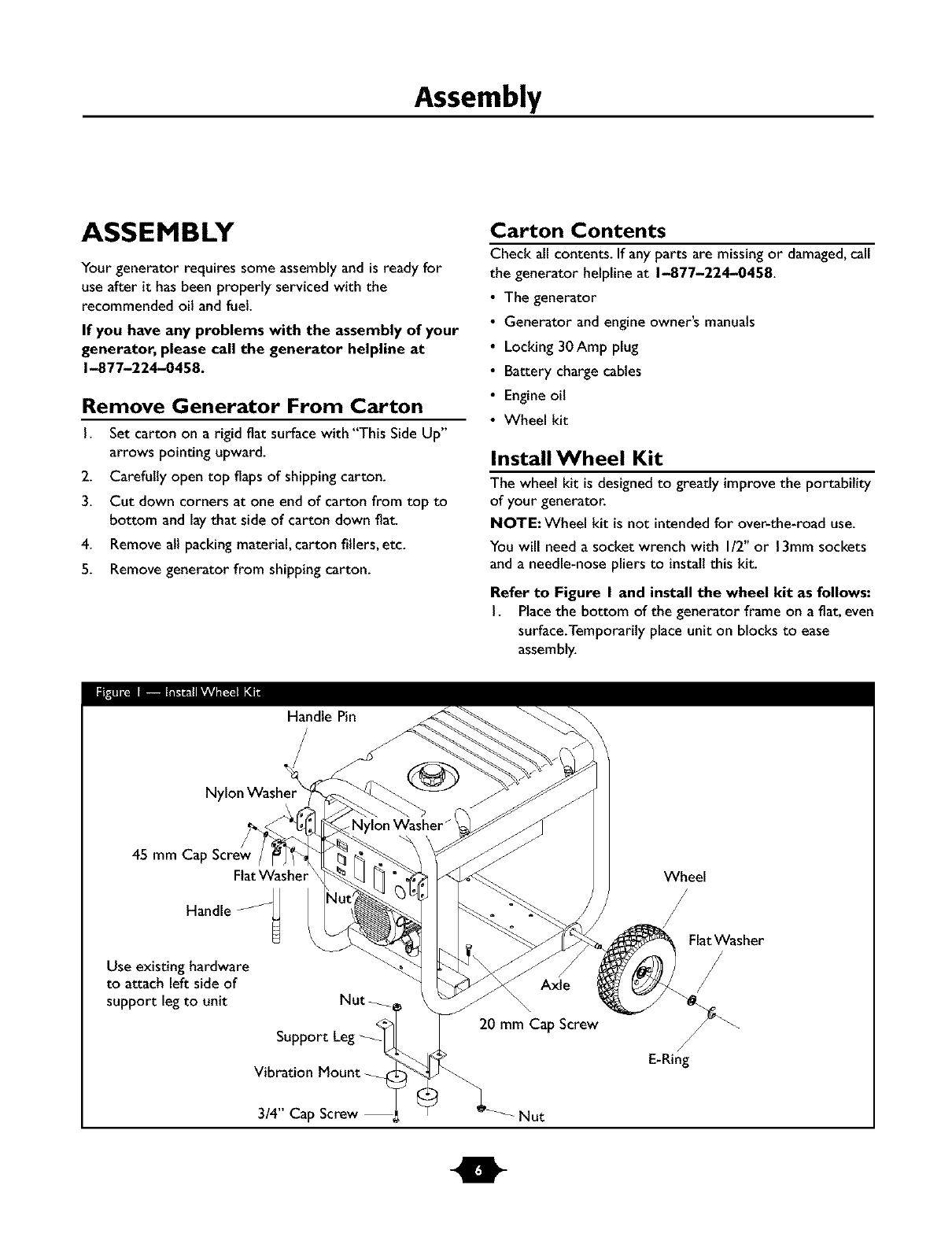
Install Wheel Kit
The wheel kit is designedto greatly improvethe portability
of your generator.
NOTE: Wheel kit is not intendedfor over-the-road use.
You will need a socket wrench with I/2" or 13mm sockets
and a needle-nose pliers to install this kit.
Refer to Figure I and install the wheel kit as follows:
I. Placethe bottom of the generator frame on a fiat, even
surface.Temporarily place unit on blocks to ease
assembly.
Handle Pin
Nylon Washer
45 mm Ca
Flat Washer
Handle
Use existing hardware
to attach left side of
support legto unit Nut
Vibration Mount
Wheel
FlatWasher
Axle
20 mm Cap Screw
/
E-Ring
3/4" Cap Screw Nut
Assembly
2. Slide axle through both axle mounting brackets on
cradle frame, as shown in Figure I.
3. Slide a wheel over the axle.
BEFORE STARTING THE
ENGINE
NOTE: Be sure to install both wheels with the air
pressure valve on the outboard side.
4. Placethe e-ring onto the groove in the axle.You may
add the fiat washer if desired.
NOTE: Use retaining pins insteadof e-clip, if applicable.
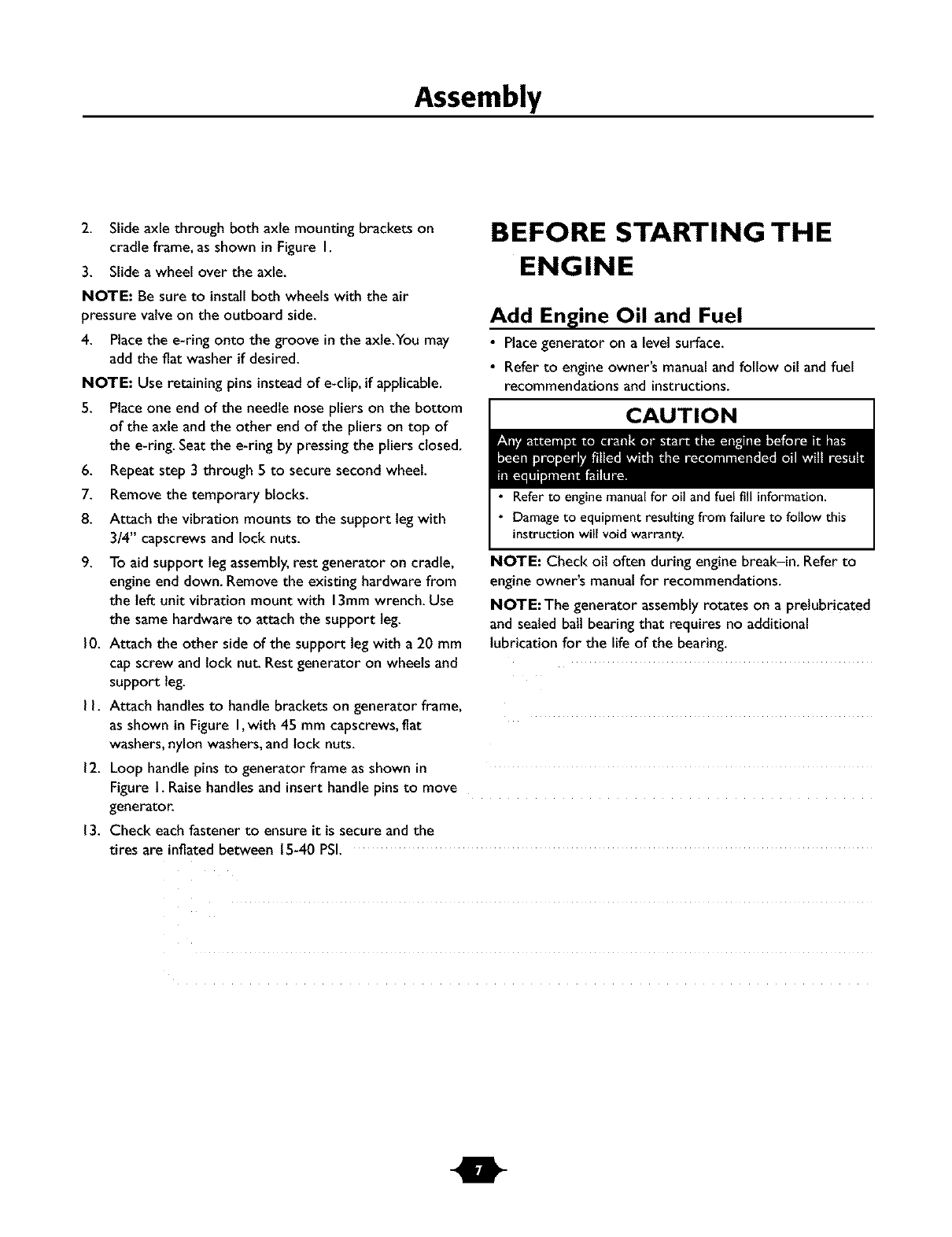
Add Engine Oil and Fuel
•Placegenerator on a levelsurface.
• Refer to engine owner's manual and follow oil and fuel
recommendations and instructions.
CAUTION
5. Place one end of the needle nose pliers on the bottom
of the axle and the other end of the pliers on top of
the e-ring. Seat the e-ring by pressing the pliers closed.
6. Repeat step 3 through 5 to secure second wheel.
7. Remove the temporary blocks.
8. Attach the vibration mounts to the support leg with
3/4" capscrews and lock nuts.
9. To aid support legassembly,rest generator on cradle,
engine end down. Remove the existing hardware from
the left unit vibrationmount with 13mmwrench. Use
the samehardware to attach the support leg.
10. Attach the other side of the support legwith a 20 mm
cap screw and lock nut. Rest generator on wheels and
support leg.
• Refer to engine manualfor oil andfuel fill information.
• Damage to equipment resulting from failure to follow this
instruction will void warranty.
NOTE: Check oil often during engine break-in. Refer to
engine owner's manual for recommendations.
NOTE:The generator assembly rotates on a pretubricated
and sealed bait bearing that requires no additional
lubricationfor the life of the bearing.
I I. Attach handlesto handle brackets on generator frame,
as shown in Figure I,with 45 mm capscrews,flat
washers,nylon washers,and lock nuts.
12. Loop handle pins to generator frame as shown in
Figure I. Raise handles and insert handle pins to move
generator.
13. Check eachfastener to ensure it is secure and the
tires are inflated between 15-40 PSI.
Operation
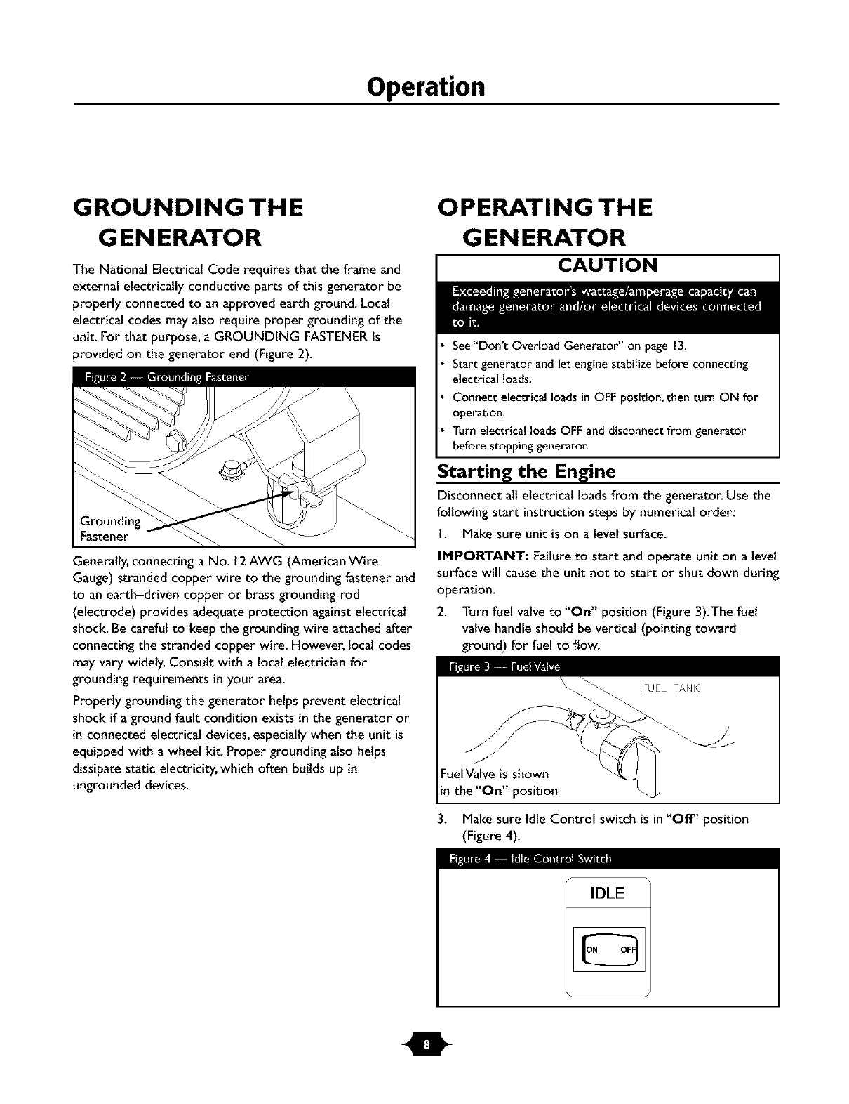
GROUNDING THE
G EN ERATO R
The National Electrical Code requires that the frame and
external electrically conductive parts of this generator be
properly connected to an approved earth ground. Local
electrical codes mayalso require proper grounding of the
unit. For that purpose, a GROUNDING FASTENERis
provided on the generator end (Figure 2).
Fastener
Generally,connecting a No. 12AWG (American Wire
Gauge) stranded copper wire to the grounding fastener and
to an earth-driven copper or brassgrounding rod
(electrode) provides adequate protection against electrical
shock. Be careful to keep the grounding wire attached after
connecting the stranded copper wire. However, local codes
may vary widely. Consult with a localelectrician for
grounding requirements in your area.
Properly grounding the generator helps prevent electrical
shock if aground fault condition exists in the generator or
in connected electrical devices,especially when the unit is
equipped with a wheel kit. Proper grounding also helps
dissipate static electricity, which often builds up in
ungrounded devices.
OPERATING THE
G EN ERATO R
CAUTION
See"Don't Overload Generator" on page 13.
Start generator and let engine stabilize before connecting
electrical loads.
Connect electrical loads in OFF position, then turn ON for
operation.
Turn electrical loads OFF and disconnect from generator
before stopping generator.
Starting the Engine
Disconnectall electrical loads from the generator. Use the
following start instructionsteps by numerical order:
I. Make sure unit is on a levelsurface.
IMPORTANT: Failureto start and operate unit on a level
surface will causethe unit not to start or shut down during
operation.
2. Turn fuel valve to "On" position (Figure 3).The fuel
valve handle should be vertical(pointing toward
ground) for fuel to flow.
Fuel Valve is shown
in the "On" position
3. Make sure Idle Control switch is in"Off" position
(Figure 4).
I_ImE_L_Ill [IL_l _"_a
IDLE
Operation
4. Start engine according to instructions given in engine
owner's manual
NOTE: If engine starts after 3 pulls but fails to run, or if
unit shuts down during operation, make sure unit is on a
level surface and check for proper oll level in crankcase.
This unit may be equipped with a low oil protection device.
See engine manual.
Connecting Electrical Loads
•Let engine stabilize and warm up for a few minutes after
starting.
• Plugin and turn on the desired 120and/or 240 VottAC,
single phase,60 Hz electrical loads.
• DO NOT connect 240Vott loads to the 120Volt duplex
receptacles.
• DO NOT connect 3-phase loads to the generator.
• DO NOT connect 50 Hz loads to the generator.
•DO NOT OVERLOADTHE GENERATOR. See
"Don't Overload Generator" on page 13.
Stopping the Engine
I. Unplug ALL electrical loads from generator panel
receptacles.NEVER start or stop engine with electrical
devices plugged in and turned ON.
2. Move idle control switch to "Off" position.
3. Let engine run at no-load for several minutes to
stabilize internal temperatures of engine and generator.
4. Turn engine off according to instructions given in the
engine owner's manual.
5. Move fuel valve to "Off" position.
Operating Automatic Idle Control
This switch is designed to greatly improvefuel economy.
When this switch is turned ON, the engine will only
run at its normal high governed engine speed when an
electrical load is connected.When an electrical load is
removed, the enginewill run at a reduced speed.With the
switch off, the engine will run at the normal high engine
speed.Always have the switch off when starting and
stopping the engine.
Charging a Battery
Your generator has the capability of recharging a discharged
12Volt automotive or utility style storage battery. DO
NOT use the unit to charge any 6Volt batteries. DO NOT
use the unit to crank an engine having a discharged battery.
DANGER
DO NOT allow any open flame, spark, heat, or lit cigarette
during and for several minutes after charging a battery.
Wear protective goggles,rubber apron, and rubber gloves.
To recharge 12Volt batteries, proceed as follows:
I. Check fluid levelin all battery cells.If necessary,add
ONLY distilled water to cover separators in battery
cells. DO NOT use tap water.
2. If battery isequipped with vent caps,make sure they
are installedand are tight.
3. If necessary,clean battery terminals.
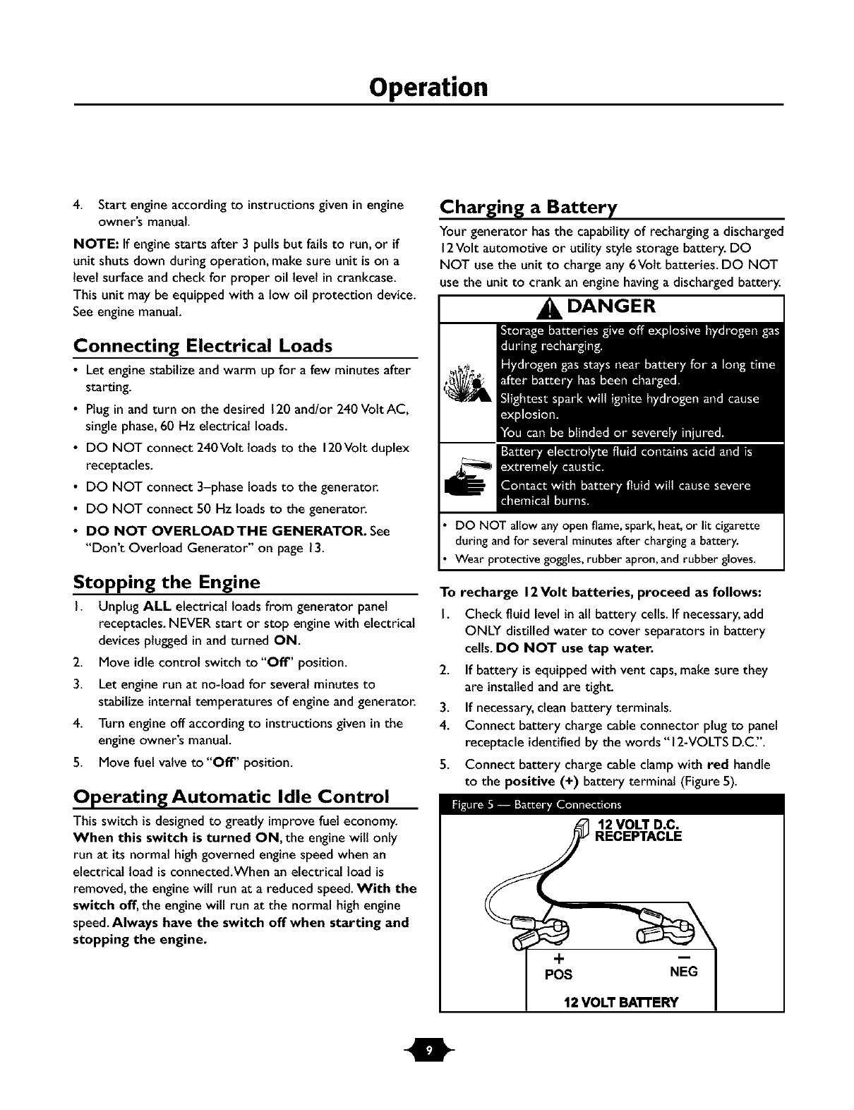
4. Connect battery charge cable connector plug to panel
receptacle identifiedby the words "12-VOLTS D.C".
5. Connect battery charge cable clamp with red handle
to the positive (+) battery terminal (Figure5).
12 VOLT D.C.
RECEPTACLE
+
POS NEG
12 VOLT BA'R'ERY
Operation
6. Connect battery charge cable clamp with black handle
to the negative (-) battery terminal (Figure5).
7. Start engine. Let engine run while battery recharges.
8. When battery has charged,shut down engine
NOTE: Use an automotive hydrometer to test battery
state of charge and condition. Follow the hydrometer
manufacturer's instructionscarefully.Generally,a battery is
considered to be at 100%state of charge when specific
gravity of its fluid (as measured by hydrometer) is 1.260 or
higher.
COLD WEATH ER
OPERATION
Under certain weather conditions (temperatures below
40°F [4°C] and a high dew point), your generator may
experience icingof the carburetor and/or the crankcase
breather system.
Build a structure that wilt enclose three sides and the top
of the generator:
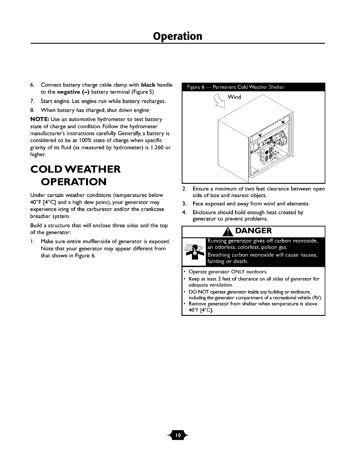
I. Make sure entire muffler-side of generator is exposed.
Note that your generator mayappear different from
that shown in Figure 6.
Wind
2. Ensure a minimum of two feet clearance between open
side of box and nearest object.
3. Face exposed end away from wind and elements.
4. Enclosure should hold enough heat created by
generator to prevent problems.
DANGER
OperategeneratorONLY outdoors.
Keepat least2 feet of clearanceon all sidesof generatorfor
adequateventilation.
DO NOT operategeneratorinsideanybuildingor enclosure,
includingthegeneratorcompartmentof arecreationalvehicle(RV).
Removegeneratorfrom shelterwhen temperatureis above
40°F[4°q.
m
Operation
RECEPTACLES
CAUTION
_:I P_tkv_ e* ••, " , m
NEVER attempt to power a device requiring more amperage
than generator or receptacle can supply.
DO NOT overload the generator. See"Don't Overload
Genera_r'.
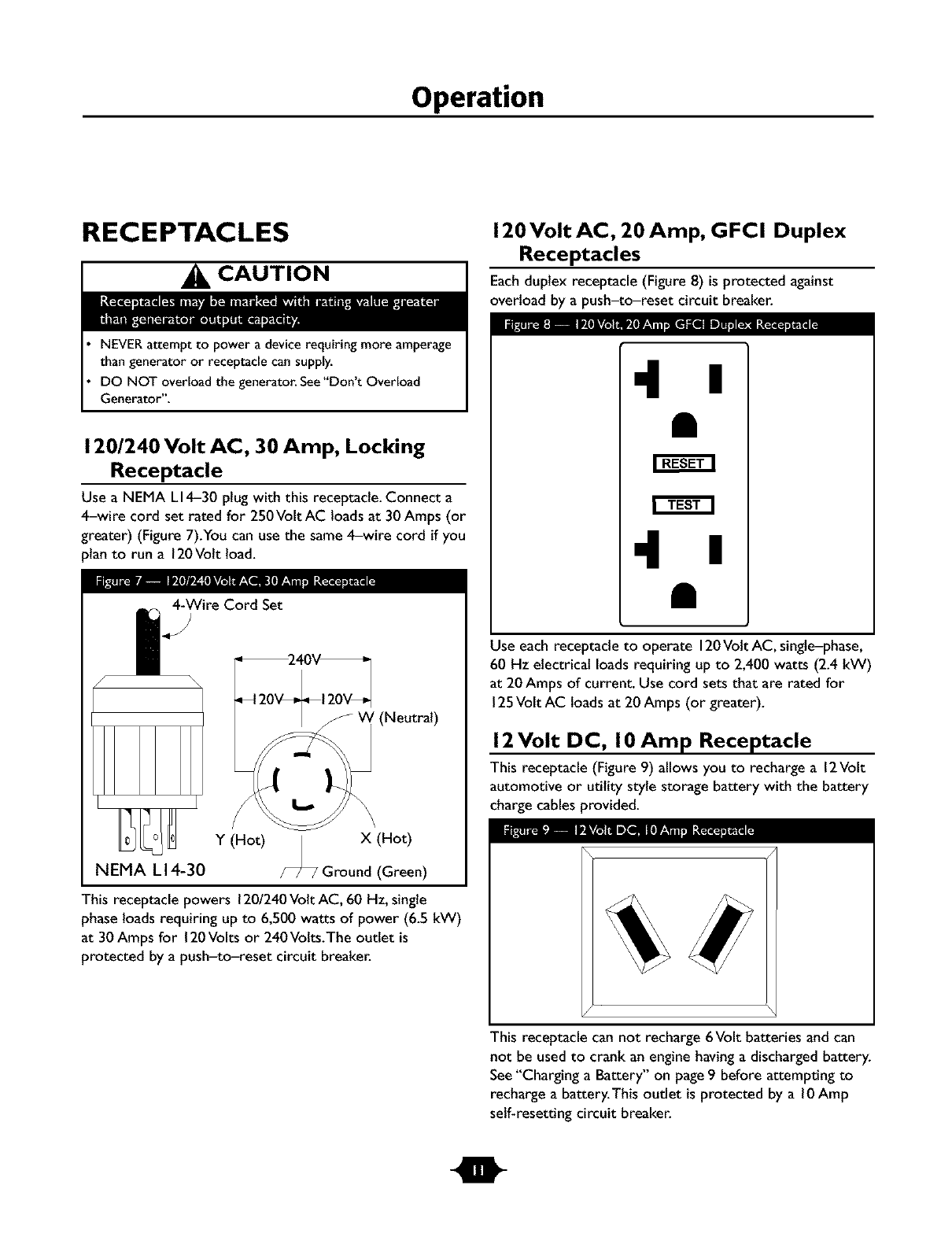
120/240 Volt AC, 30 Amp, Locking
Receptacle
Use a N EMA LI4-30 plug with this receptacle.Connect a
4-wire cord set rated for 250Volt AC loads at 30 Amps (or
greater) (Figure 7).You can use the same 4-wire cord if you
)lan to run a 120Volt load.
4-WireCord Set
/-
'(Neutral)
IPE_ _ 1[*TA_m
Y(Hot) | X (Hot)
NEMA L 14-30 /-_ Ground (Green)
This receptacle powers 1201240Volt AC, 60 Hz, single
phase loadsrequiring up to 6,500 watts of power (6.5 kW)
at 30 Amps for 120Volts or 240Volts.The outlet is
protected by a push-to-reset circuit breaker.
120 Volt AC, 20 Amp, GFCI Duplex
Receptacles
Each duplex receptacle (Figure 8) is protected against
overload by a push-to-reset circuit breaker.
•l I
•l I
Use each receptacle to operate 120Volt AC, single-phase,
60 Hz electrical loadsrequiring up to 2,400 watts (2.4 kW)
at 20Amps of current. Use cord sets that are rated for
125Volt AC loads at 20Amps (or greater).
12Volt DC, I 0 Amp Receptacle
This receptacle (Figure 9) allows you to recharge a 12Volt
automotive or utility style storage battery with the battery
charge cables provided.
This receptacle can not recharge 6Volt batteries and can
not be used to crank an engine having a discharged battery.
See"Charging a Battery" on page9 before attempting to
recharge a battery.This outlet is protected by a l0 Amp
self-resetting circuit breaker.
I
Operation
Ground Fault Protection
This unit is equipped with a Ground Fault Circuit
Interrupter (GFCI).This device meets applicable federal,
state and local codes.
The GFCI protects againstelectrical shock that may be
caused if your body becomes a path which electricity
travels to reach the ground.This could happen if you touch
a "Live" applianceor wire, or are touching plumbing or
other materials that connect to the ground.
When protected by a GFCI, one maystill feel a shock, but
the GFCI should cut current off quickly enough so that a
person in normal health should not suffer any serious
electrical injury.
DANGER
The GFCI will not protect you againstthe following situations:
-Line-to-line shocks;
-Current overloads or line-to-line short circuits.
The fuse or circuit breaker at the control panel must provide
such protection.
Testing the GFCI
Test your GFCI outlet every month and before use,as
follows:
• Push the black"Test" button.The red "Reset" button
should pop out, which should allow no power to reach
the outlet. Use atest lamp in each outlet to test this.
CAUTION
DO NOT useanyoutlets on the circuit.
Call aqualifiedelectrician.
If the GFCI tests good, restore power by pressingthe
"Reset" button firmly until it is fully in place and locks in
that position. If the GFCI outlet does not reset
properly, do not use the outlet. Call a local service
center.
If the GFCI trips by itself at any time, reset and test the
outlet. If the reset button does pop out when the
test button is pressed, do not use the outlet. Call
a local service center.
m
Operation
DON'T OVERLOAD
G EN ERATO R
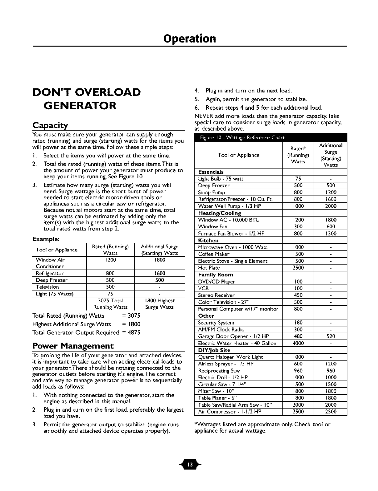
Capacity
You must make sure your generator cansupply enough
rated (running) and surge (starting) watts for the items you
will power at the sametime. Follow these simple steps:
I. Select the itemsyou wilt power at the same time.
2. Total the rated (running) watts of these items.This is
the amount of power your generator must produce to
keep your items running. SeeFigure 10.
3. Estimate how many surge (starting) watts you wilt
need. Surge wattage is the short burst of power
needed to start electric motor+driven tools or
appliancessuch as a circular saw or refrigerator.
Becausenot all motors start at the sametime, total
surge watts can be estimated by addingonly the
item(s) with the highest additional surge watts to the
total rated watts from step 2.
Example:
Tool or Appliance
Window Air
Conditioner
Refrigerator
Deep Freezer
Television
Light (75 Watts)
Rated (Running)
Watts
1200
800
500
500
75
3075 Total
Running Watts
Total Rated (Running)Watts = 3075
Highest Additional SurgeWatts = 1800
Total Generator Output Required = 4875
Additional Surge
(Starting)Watts
1800
1600
50O
1800 Highest
Surge Watts
Power Management
To prolong the life of your generator and attached devices,
it is important to take care when addingelectrical loads to
your generator.There should be nothing connected to the
generator outlets before starting it's engine.The correct
and safeway to managegenerator power is to sequentially
add loads as follows:
I. With nothing connected to the generator, start the
engine as described in this manual.
2. Plugin and turn on the first load, preferably the largest
load you have.
3. Permit the generator output to stabilize (engine runs
smoothly and attached device operates properly).
4. Plug in and turn on the next load.
5. Again, permit the generator to stabilize.
6. Repeat steps 4 and 5 for each additional load.
NEVER add more loads than the generator capacity.Take
specialcare to consider surge loads in generator capacity,
as described above.
Tool or Appliance
Essentials
Light Bulb - 75 watt
Deep Freezer
SumpPump
Refrigerator/Freezer - 18Cu. Ft.
Water Well Pump- I/3 HP
Heating/Cooling
Window AC - IO,O00BTU
Window Fan
FurnaceFanBlower - I/2 HP
Kitchen
Microwave Oven - 1000Watt
Coffee Maker
Electric Stove - SingleElement
Hot Plate
Family Room
DVD/CD Player
VCR
Stereo Receiver
Color Television - 27"
Personal Computer w/I 7" monitor
Other
SecuritySystem
AM/FM Clock Radio
Garage Door Opener - I/2 HP
Electric Water Heater - 40 Gallon
DIY/Job Site
Quartz Halogen Work Light
Airless Sprayer - I/3 HP
Reciprocating Saw
Electric Drill - I/2 HP
Circular Saw - 7 I/4"
Miter Saw - 10"
Table Planer - 6"
Table Saw/RadialArm Saw - 10"
Air Compressor - I-I/2 HP
Rated*
(Running)
Watts
75
5O0
8O0
8O0
1000
12O0
3OO
8O0
1000
1500
1500
25O0
Ioo
Ioo
450
5O0
8O0
Additional
Surge
(Starting)
Watts
5O0
1200
1600
20O0
1800
6O0
1300
180
300
480 520
40O0
1000
600 1200
960 960
1000 1000
1500 1500
1800 1800
1800 1800
2000 2000
2500 2500
*Wattages listed are approximate only. Check toot or
appliance for actual wattage.
m
Maintenance
SPECIFICATIONS
Maximum SurgeWatts ................. 8,125 watts
Continuous Wattage Capacity ........... 6,500 watts
Power Factor .............................. 1.0
Rated Maximum Continuous AC Load Current:
At 120Volts ....................... 54.2 Amps
At 240 Volts ....................... 27. I Amps
Phase................................. I-phase
Rated Frequency ....................... 60 Hertz
FuelTank Capacity................... 7 U.S.gallons
ShippingWeight ......................... 205 Ibs.
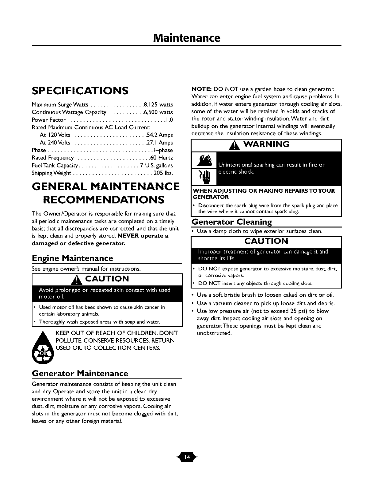
GENERAL MAINTENANCE
RECOMMENDATIONS
The Owner/Operator is responsible for making sure that
all periodic maintenance tasks are completed on atimely
basis;that all discrepancies are corrected; and that the unit
is kept clean and properly stored. NEVER operate a
damaged or defective generator.
Engine Maintenance
See engine owner's manual for instructions.
CAUTION
Used motor oil has been shown to cause skin cancer in
certain laboratory animals.
Thoroughly wash exposed areas with soap and water.
KEEPOUT OF REACH OF CHILDREN. DON'T
POLLUTE. CONSERVE RESOURCES.RETURN
USED OIL TO COLLECTION CENTERS.
Generator Maintenance
Generator maintenance consists of keeping the unit clean
and dry. Operate and store the unit in a clean dry
environment where it will not be exposed to excessive
dust, dirt, moisture or any corrosive vapors. Cooling air
slots in the generator must not become clogged with dirt,
leaves or any other foreign material.
NOTE: DO NOT use a garden hose to clean generator.
Water can enter engine fuel system and causeproblems. In
addition, if water enters generator through cooling air slots,
some of the water wilt be retained in voidsand cracks of
the rotor and stator winding insulation.Waterand dirt
buildup on the generator internal windings will eventually
decreasethe insulationresistance of these windings.
ENERATOR
WARNING
Disconnect the spark plug wire from the spark plug and place
the wire where it cannot contact spark plug.
Generator Cleaning
• Use a damp cloth to wipe exterior surfaces clean.
CAUTION
DO NOT expose generator to excessive moisture, dust, dirt,
or corrosive vapors.
DO NOT insert any objects through cooling slots.
Use a soft bristle brush to loosen caked on dirt or oil.
Use a vacuum cleaner to pick up loose dirt and debris.
Use low pressure air (not to exceed 25 psi) to blow
away dirt. Inspect cooling air slots and opening on
generator.These openings must be kept clean and
unobstructed.
m

Storage
STO RAG E
The generator should be started at least once every seven
claysand allowed to run at least 30 minutes. If this cannot
be done and you must store the unit for more than
30 days,use the following guidelines to prepare it for
storage.
Generator Storage
•Clean the generator as outlined in "Generator Cleaning".
• Check that cooling air slots and openings on generator
are open and unobstructed.
WARNING
DO NOT place a storage cover over a hot generator.
Let equipment cool for a sufficient time before placing the
cover on the equipment.
Engine Storage
See engine owner's manual for instructions.
Other Storage Tips
• To prevent gum from forming in fuel system or on
essential carburetor parts, add fuel stabilizer into fuel
tank and fill with fresh fuel. Run the unit for several
minutes to circulate the additive through the carburetor.
The unit and fuel can then be stored for up to
24 months. Fuel stabilizer can be purchased locally.
• DO NOT store fuel from one season to another unless
it has been treated as described above.
• Replace fuel container if it starts to rust. Rust and/or dirt
in fuel can cause problems if it's used with this unit.
• Store unit in a clean and dry area.
I

Notes
NOTES
Troubleshooting
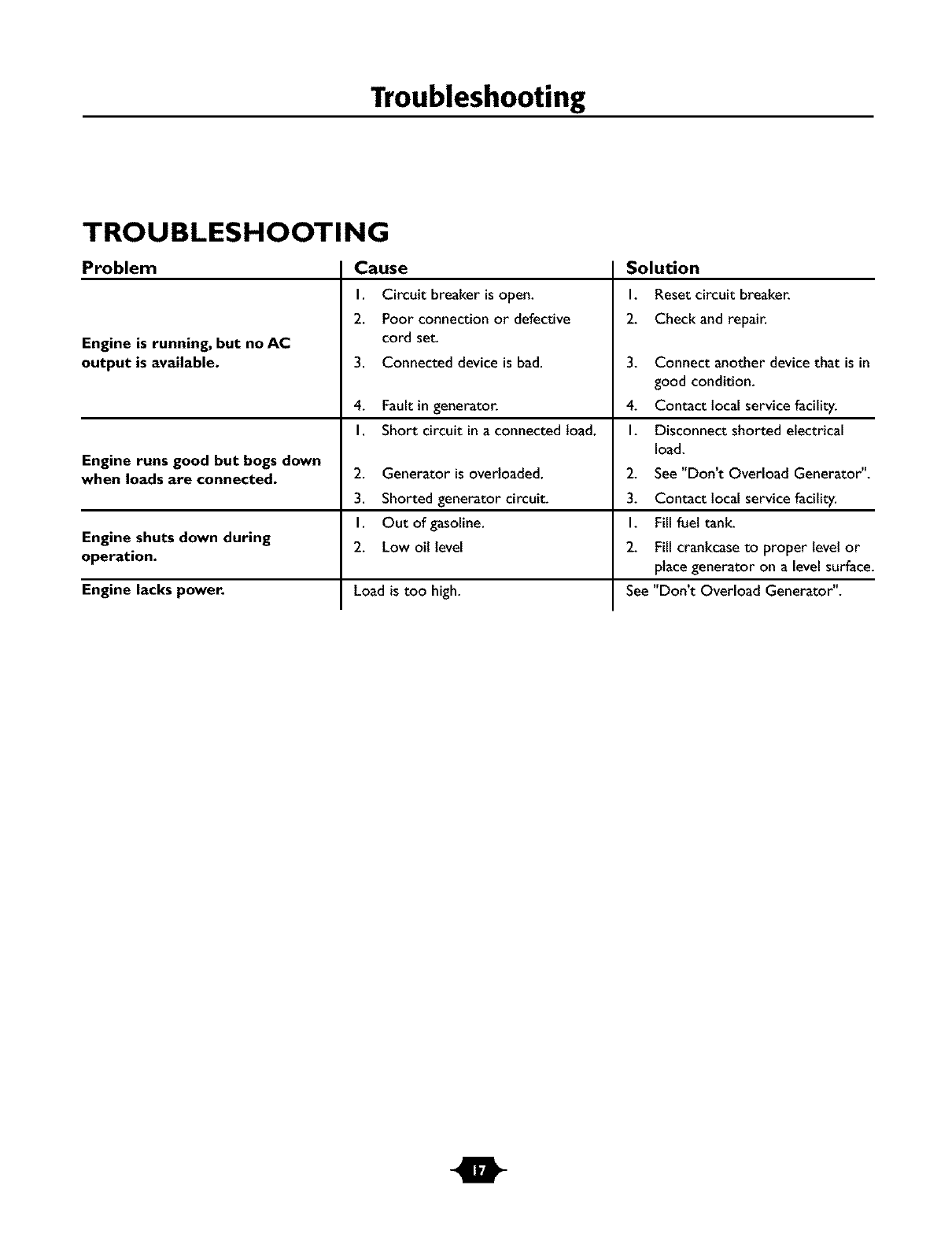
TROUBLESHOOTING
Problem
Engine is running, but no AC
output is available.
Cause
I. Circuit breaker isopen.
2. Poor connection or defective
cord set.
3. Connected device is bad.
Solution
I. Reset circuit breaker.
2. Check and repair.
.
4. Fault in generator. 4.
I. Short circuit in a connected load. I.
Engine runs good but bogs down
when loads are connected. 2. Generator is overloaded. 2.
3. Shorted generator circuit. 3.
I. Out of gasoline. I.
Engine shuts down during 2. Low oil level 2.
operation.
Engine lacks power. Load is too high. See
Connect another devicethat is in
good condition.
Contact local service facility.
Disconnect shorted electrical
load.
See "Don't Overload Generator".
Contact local service facility.
Fill fuel tank.
Fill crankcaseto proper level or
place generator on a level surface.
"Don't Overload Generator".
m
Schematic
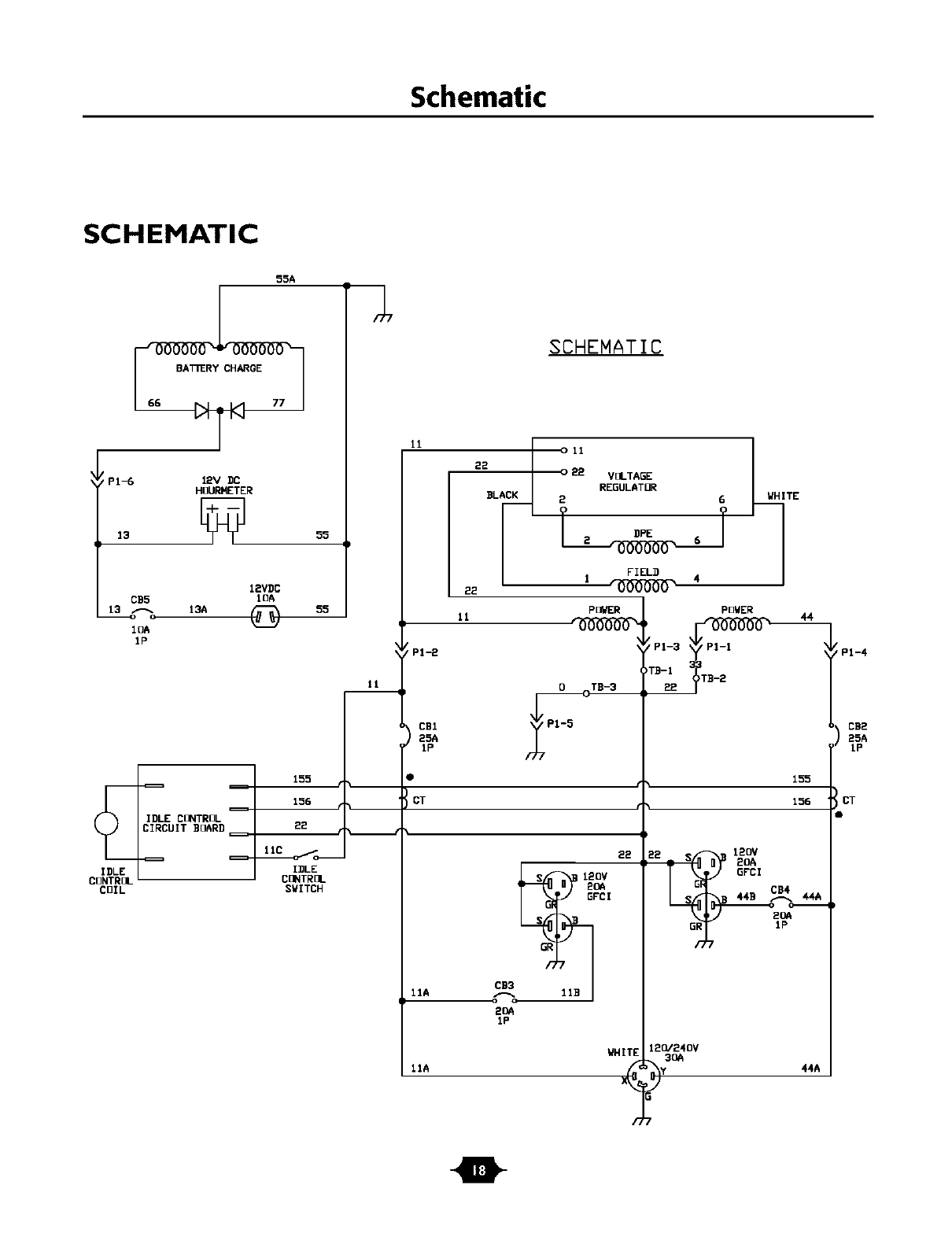
SCHEMATIC
55A
//PI-6 12V DC
HOURMETER
55
12VDC
CB5 10A
13 _ 13A (_ 55
IOA
1P
IDLE CONTROL
CIRCUIT BOARD
IDLE
CONTROL
COIL
J,
11
155
156
IDLE
CONTROL
SWITCH
SCHEMATIC
11
P1-2
o 11
o 22 VOLTAGE
REGULATOR
2 6
FIEL_
POWER
.._TB-3
CT
IIA
11A
EE
sI20V
GFD!
GR
2OA
1P
WHITE
POWER
;P1-3
TB-122 _TB-2
155
156
P
E2 120V
mS 2OA
GFCI
IP
12O/24OV
3OA
_y 44A
t
PPI-4
CB2
25A
IP
CT
m
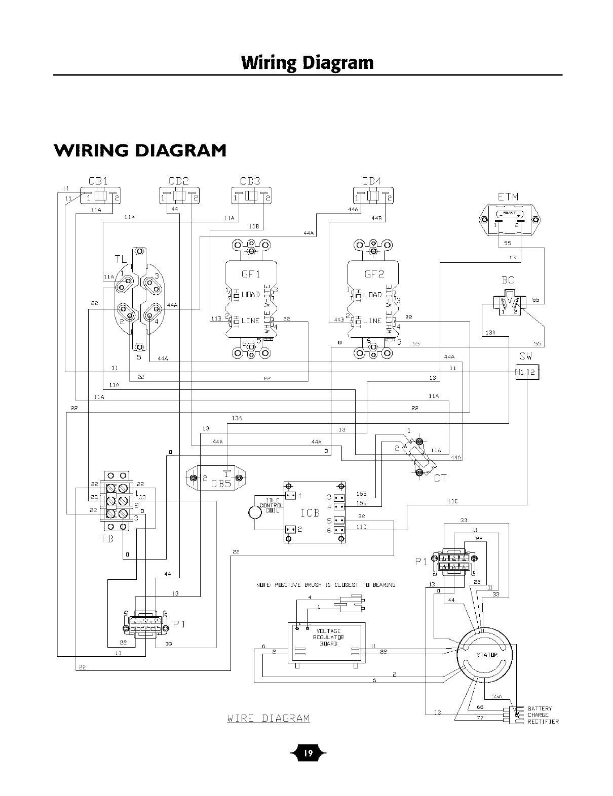
Wiring Diagram
WIRING DIAGRAM
CB1 CS£ CB3 CS4
88
@F1
13A
2_
44A
11
13
22
L3 128 IIA
0A
44A
i 3 155 llC
4
CB s aa
6
NI]rE_ pI]EITIVE BRUEH IS CLDEEET TI] BEARIN@
6
WIRE DIAGRAH
22
2
ETH
33
11
1 1133
STAT[IR
55A
66
13
SW
m
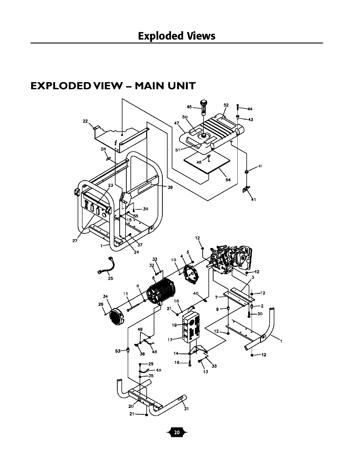
Exploded Views
EXPLODEDVIEW- MAIN UNIT
52
27
25
34
26
6
5
10
12
\
_12
33
13
31
0
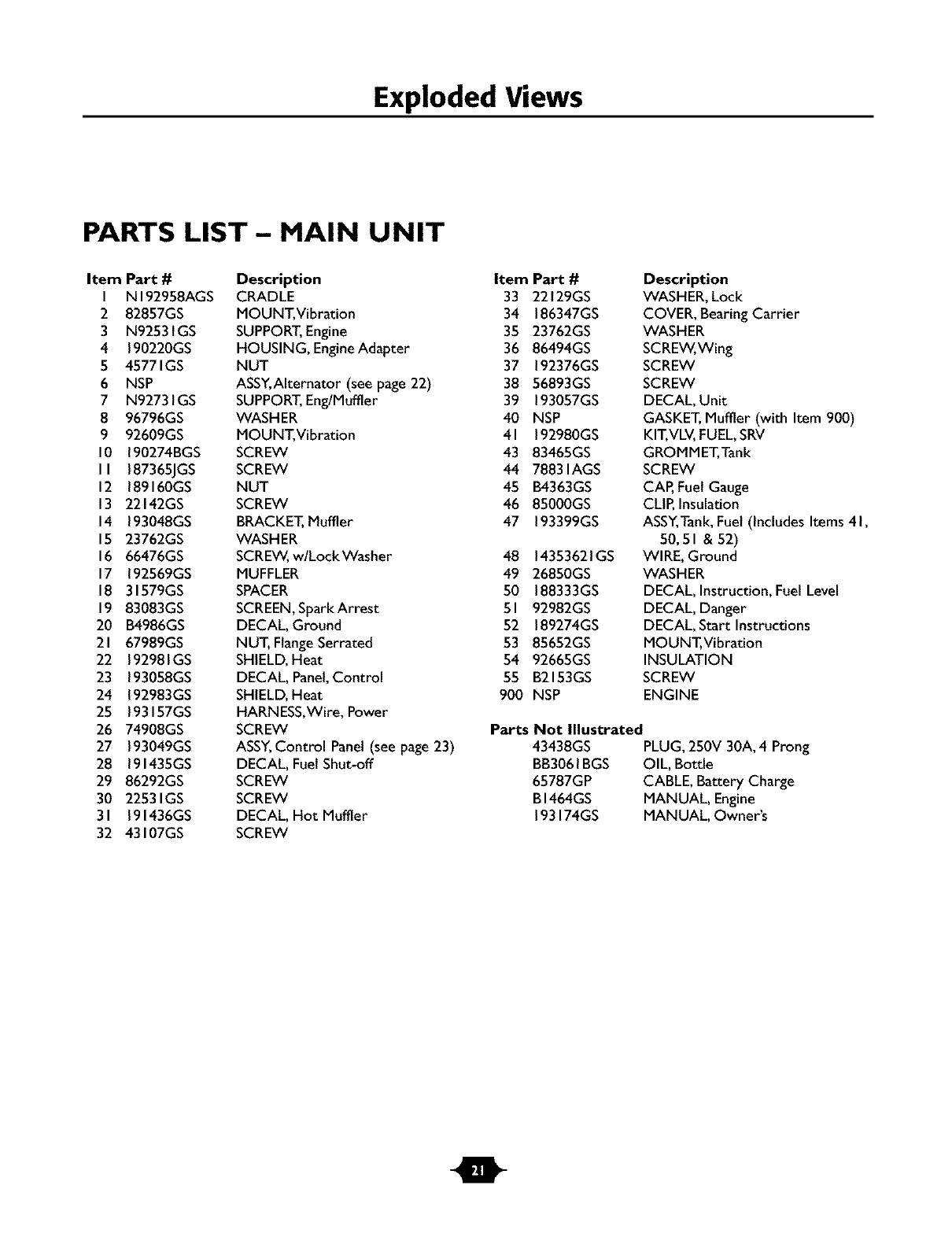
Exploded Views
PARTS LIST - MAIN UNIT
Item Part # Description
I NI92958AGS CRADLE
2 82857GS MOUNT, Vibration
3 N92531GS SUPPORT,Engine
4 190220GS HOUSING, EngineAdapter
5 45771GS NUT
6 NSP ASSY,AIternator (see page 22)
7 N92731GS SUPPORT,Eng/Muffler
8 96796GS WASHER
9 92609GS MOUNT, Vibration
10 190274BGS SCREW
II 187365JGS SCREW
12 189160GS NUT
13 22142GS SCREW
14 193048GS BRACKET,Muffler
15 23762GS WASHER
16 66476GS SCREW,w/Lock Washer
17 192569GS MUFFLER
18 31579GS SPACER
19 83083GS SCREEN,Spark Arrest
20 B4986GS DECAL, Ground
21 67989GS NUT, FlangeSerrated
22 192981GS SHIELD,Heat
23 193058GS DECAL, Panel,Control
24 192983GS SHIELD,Heat
25 193157GS HARNESS,Wire, Power
26 74908GS SCREW
27 193049GS ASSY,Control Panel(see page23)
28 191435GS DECAL, Fuel Shut-off
29 86292GS SCREW
30 2253 IGS SCREW
31 191436GS DECAL, Hot Muffler
32 43107GS SCREW
Item Part # Description
33 22129GS WASHER, Lock
34 186347GS COVER, Bearing Carrier
35 23762GS WASHER
36 86494GS SCREW,Wing
37 192376GS SCREW
38 56893GS SCREW
39 193057GS DECAL, Unit
40 NSP GASKET,Muffler (with Item 900)
41 192980GS KIT,VLV,FUEL,SRV
43 83465GS GROMMET,Tank
44 7883 lAGS SCREW
45 B4363GS CAP,Fuel Gauge
46 85000GS CLIP,Insulation
47 193399GS ASSY,Tank,Fuel (includes Items 41,
50,51 &52)
48 14353621GS WIRE, Ground
49 26850GS WASHER
50 188333GS DECAL, Instruction, Fuel Level
51 92982GS DECAL, Danger
52 189274GS DECAL, Start Instructions
53 85652GS MOUNT, Vibration
54 92665GS INSULATION
55 B2153GS SCREW
900 NSP ENGINE
Parts Not Illustrated
43438GS PLUG, 250V 30A, 4 Prong
BB3061BGS OIL, Bottle
65787GP CABLE, Battery Charge
B1464GS MANUAL, Engine
193174GS MANUAL, Owner's
t
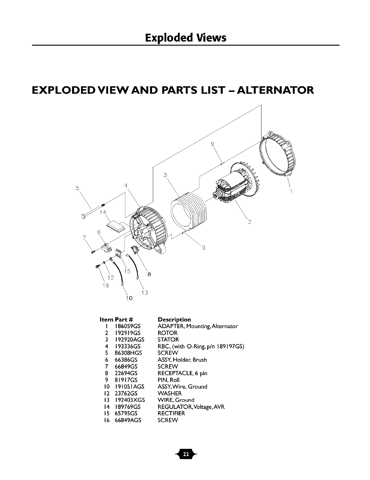
Exploded Views
EXPLODED VI EW AND PARTS LIST - ALTERNATOR
5 4
\\\\\
\
6
7\\ \9
\\\\\
2
8
16 \\, 1,5
10
Item Part #
I 186059GS
2 192919GS
3 192920AGS
4 193336GS
5 86308HGS
6 66386GS
7 66849GS
8 22694GS
9 81917GS
10 19105lAGS
12 23762GS
13 192403XGS
14 189769GS
15 65795GS
16 66849AGS
Description
ADAPTER, Mounting, Alternator
ROTOR
STATOR
RBC, (with O-Ring, p/n 189197GS)
SCREW
ASSY,Holder, Brush
SCREW
RECEPTACLE,6 pin
PIN, Roll
ASSY,Wire, Ground
WASHER
WIRE, Ground
REGULATO R,Voltage,AVR
RECTIFIER
SCREW
m
Exploded Views
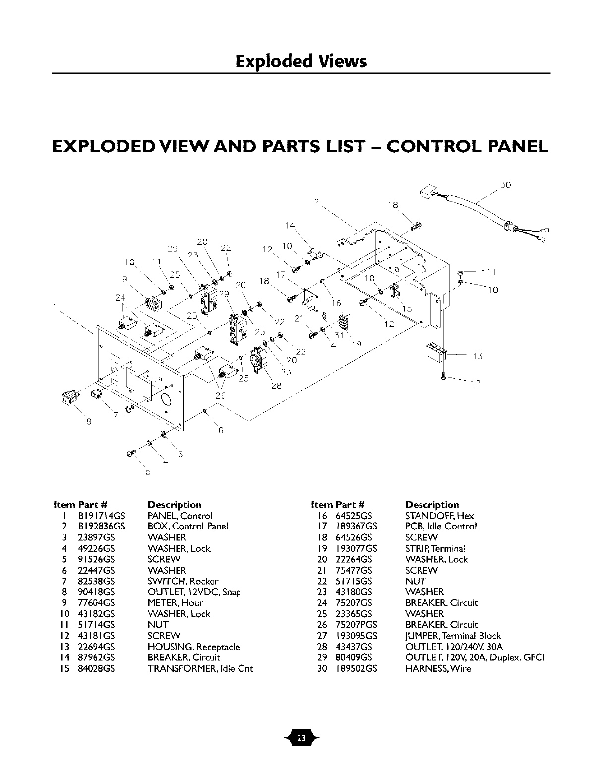
EXPLODED VIEW AND PARTS LIST- CONTROL PANEL
8
20
29 22 12
10 11
\\
9 \ 20 18
24
5
26
14
2O
23
\/
28 /
2
12
31 \ //
4 19 /
12
Item Part #
I BI91714GS
2 BI92836GS
3 23897GS
4 49226GS
5 91526GS
6 22447GS
7 82538GS
8 90418GS
9 77604GS
10 43182GS
II 51714GS
12 43181GS
13 22694GS
14 87962GS
15 84028GS
Description
PANEL,Control
BOX, Control Panel
WASHER
WASHER, Lock
SCREW
WASHER
SWITCH, Rocker
OUTLET, 12VDC, Snap
METER,Hour
WASHER, Lock
NUT
SCREW
HOUSING, Receptacle
BREAKER,Circuit
TRANSFORMER, Idle Cnt
Item Part #
16 64525GS
17 189367GS
18 64526GS
19 193077GS
20 22264GS
21 75477GS
22 51715GS
23 43180GS
24 75207GS
25 23365GS
26 75207PGS
27 193095GS
28 43437GS
29 80409GS
30 189502GS
Description
STANDOFF,Hex
PCB,Idle Control
SCREW
STRIP,Terminal
WASHER, Lock
SCREW
NUT
WASHER
BREAKER,Circuit
WASHER
BREAKER,Circuit
JUMPER,Terminal Block
OUTLET, 120/240V,30A
OUTLET, 120V,20A, Duplex. GFCI
HARNESS,Wire
m
Exploded Views
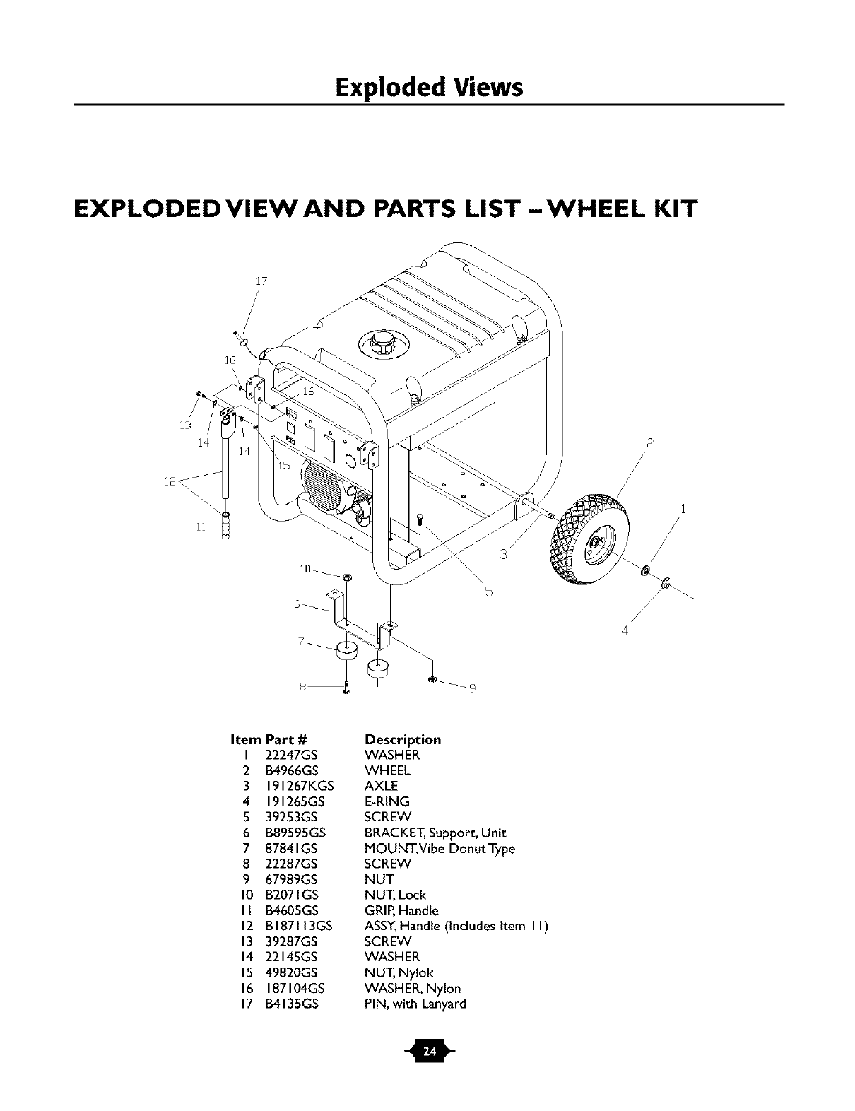
EXPLODEDVIEWAND PARTS LIST-WHEEL KIT
13
3
Item Part#
I 22247GS
2 B4966GS
3 191267KGS
4 191265GS
5 39253GS
6 B89595GS
7 87841GS
8 22287GS
9 67989GS
10 B2071GS
II B4605GS
12 BI87113GS
13 39287GS
14 22145GS
15 49820GS
16 187104GS
17 B4135GS
Description
WASHER
WHEEL
AXLE
E-RING
SCREW
BRACKET,Support, Unit
MOUNT, Vibe Donut Type
SCREW
NUT
NUT, Lock
GRIP,Handle
ASSY,Handle (includes Item II)
SCREW
WASHER
NUT, Nylok
WASHER, Nylon
PIN, with Lanyard
m
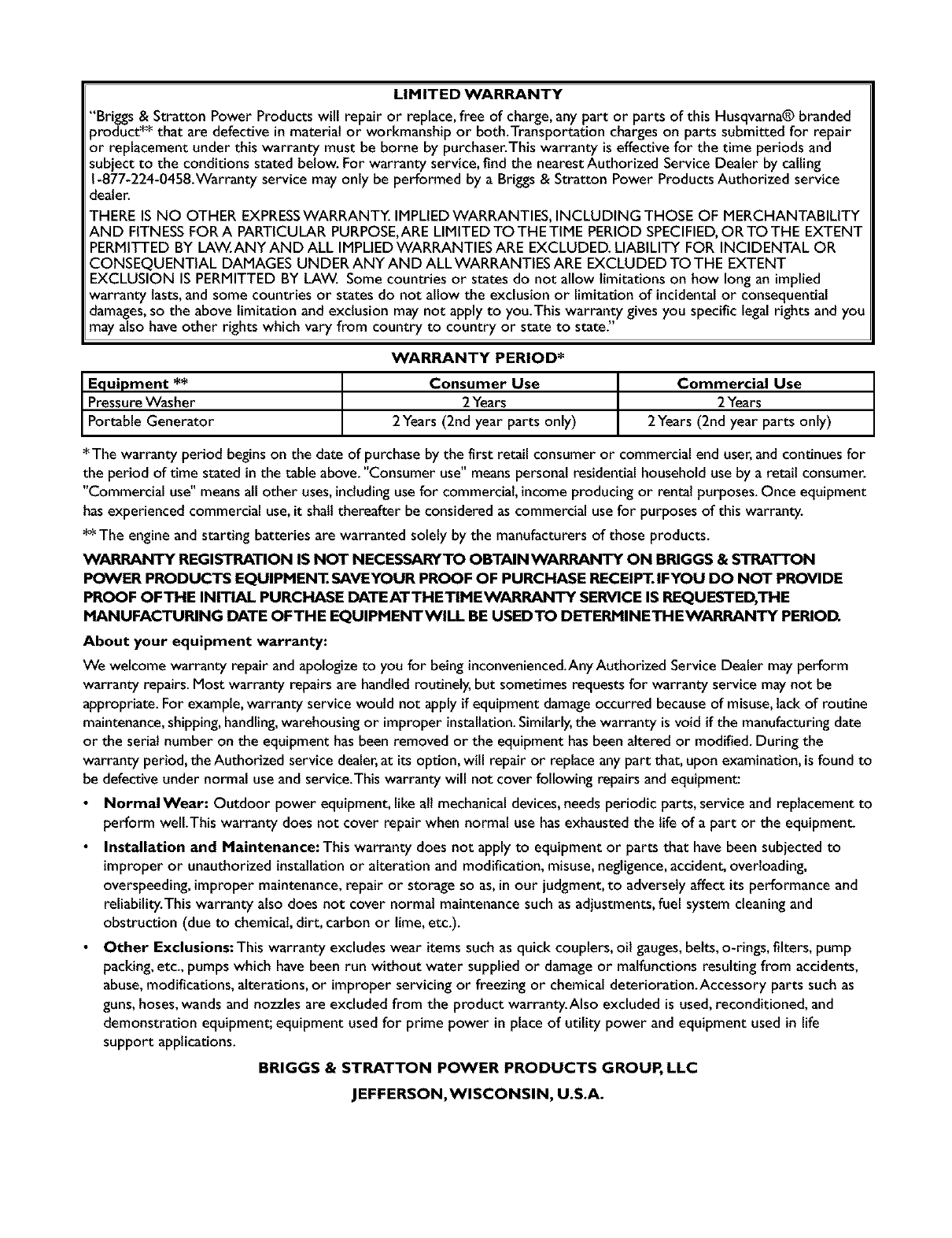
LIMITED WARRANTY
"Briggs & Stratton Power Products will repair or replace,free of charge, any part or parts of this Husqvarna® branded
product** that are defective in material or workmanship or both.Transportation charges on parts submitted for repair
or replacement under this warranty must be borne by purchaser.This warranty is effective for the time periods and
subject to the conditions stated below. For warranty service, find the nearestAuthorized Service Dealer by calling
1-877-224-0458.Warranty service may only be performed by a Briggs & Stratton Power Products Authorized service
dealer.
THERE IS NO OTHER EXPRESSWARRANTY. IMPLIEDWARRANTIES, INCLUDING THOSE OF MERCHANTABILITY
AND FITNESSFORA PARTICULAR PURPOSE,ARELIMITED TO THE TIME PERIOD SPECIFIED,OR TO THE EXTENT
PERMITTED BY LAW.ANY AND ALL IMPLIEDWARRANTIES ARE EXCLUDED. LIABILITY FOR INCIDENTAL OR
CONSEQUENTIAL DAMAGES UNDER ANY AND ALL WARRANTIES ARE EXCLUDED TO THE EXTENT
EXCLUSION IS PERMITTED BY LAW. Some countries or states do not allow limitations on how long an implied
warranty lasts,and some countries or states do not allow the exclusion or limitationof incidentalor consequential
damages,so the above limitationand exclusion may not apply to you.This warranty givesyou specific legal rights and you
may also have other rights which vary from country to country or state to state."
WARRANTY PERIOD*
Equipment ** Consumer Use Commercial Use
PressureWasher 2Years 2Years
Portab e Generator 2Years (2nd year parts only) 2Years (2nd year parts only)
*The warranty period beginson the date of purchase bythe first retail consumer or commercial end user,and continues for
the period of time stated in the table above."Consumer use" meanspersonal residential household use by a retait consumer.
"Commercial use" meansall other uses,includinguse for commercial, incomeproducing or rental purposes.Once equipment
has experienced commercial use,it shall thereafter be considered as commercial use for purposes of this warranty.
**The engine and starting batteries are warranted solely by the manufacturers of those products.
WARRANTY REGISTRATION IS NOT NECES_0d_YTO OBTAIN WARRANTY ON BRIGGS &S_TTON
POWER PRODUCTS EQUIPMENT.SAVEYOUR PROOF OF PURCHASE RECEIPT.IFYOU DO NOT PROVIDE
PROOF OFTHE INITIAL PURCHASE DATEATTHETIMEWARRANTY SERVICE IS REQUESTED,THE
MANUFACTURING DATE OFTHE EQUIPMENTWILL BE USEDTO DETERMINETHEWARRANTY PERIOD.
About your equipment warranty:
We welcomewarranty repair and apologize to you for being inconvenienced.AnyAuthorized Service Dealer may perform
warranty repairs.Most warranty repairs are handled routinely, but sometimes requests for warranty service may not be
appropriate. For example,warranty service would not apply if equipment damageoccurred becauseof misuse,lack of routine
maintenance,shipping,handling,warehousing or improper installation.Similarly,the warranty is void if the manufacturingdate
or the serial number on the equipment hasbeen removed or the equipment hasbeen altered or modified. During the
warranty period, the Authorized service dealer,at its option, will repair or replace any part that, upon examination, isfound to
be defective under normal use and service.This warranty will not cover following repairs and equipment:
Normal Wear: Outdoor power equipment, llke alt mechanical devices,needs periodic parts, service and replacement to
perform welLThls warranty does not cover repair when normal use hasexhausted the llfe of a part or the equipment
Installation and Maintenance: Thls warranty does not apply to equipment or parts that have been subjected to
improper or unauthorized installationor alteration and modification, misuse,negligence,accident, overloading,
overspeeding, improper maintenance,repair or storage so as,inour judgment, to adversely affect its performance and
reliability.This warranty also does not cover normal maintenance such as adjustments, fuel system cteaningand
obstruction (due to chemical,dirt, carbon or lime, etc.).
• Other Exclusions: This warranty excludes wear itemssuch as quick couplers, oil gauges,belts, o-rings, filters, pump
packing,etc., pumps which have been run without water supplied or damage or malfunctions resulting from accidents,
abuse,modifications, alterations, or improper servicing or freezing or chemical deterioration.Accessory parts such as
guns,hoses,wands and nozzles are excluded from the product warranty.Also excluded is used,reconditioned, and
demonstration equipment; equipment used for prime power in place of utility power and equipment used in life
support applications.
BRIGGS &STRATTON POWER PRODUCTS GROUP, LLC
JEFFERSON,WISCONSIN, U.S.A.
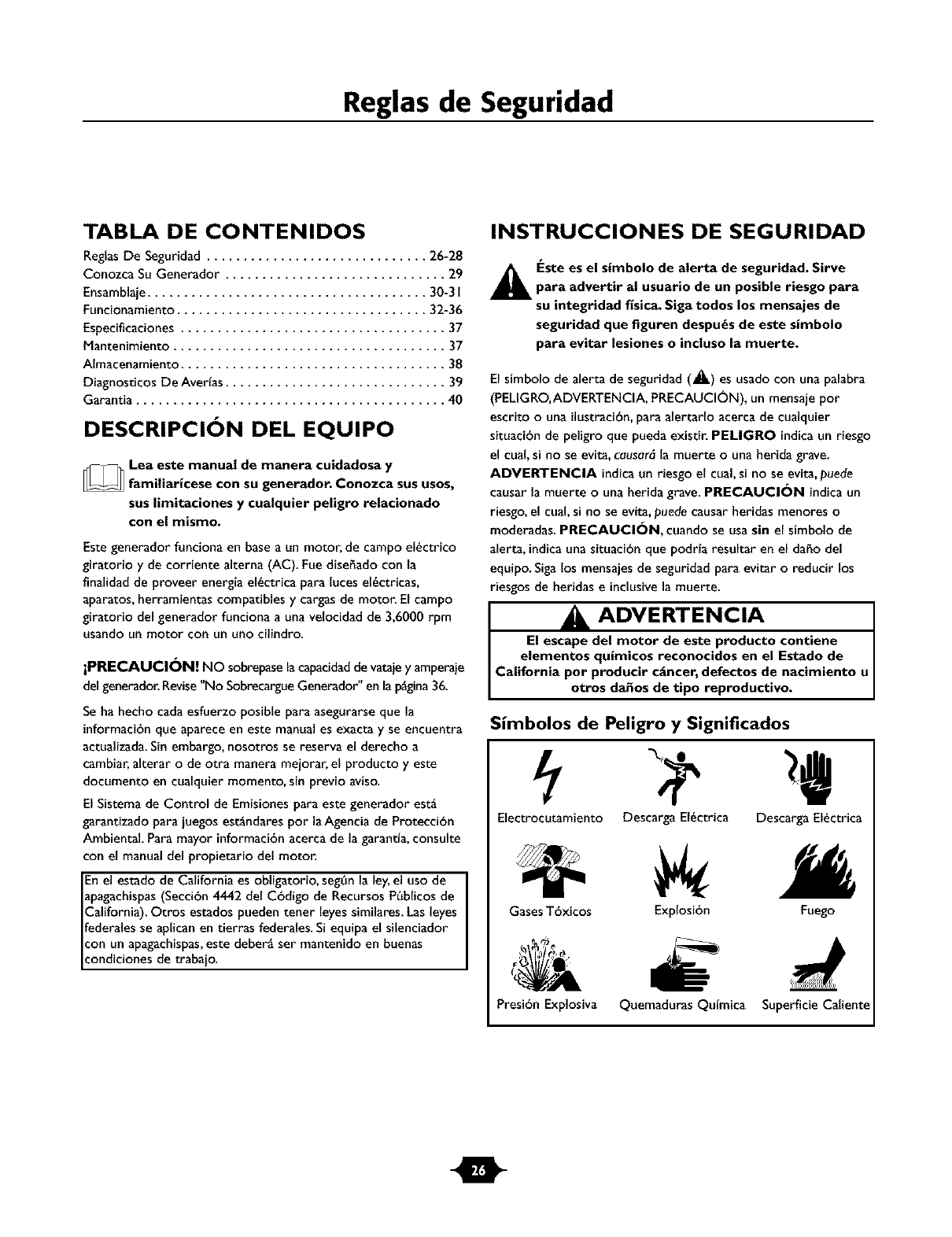
Reglas de Seguridad
TABLA DE CONTENIDOS
ReglasDe Seguridad .............................. 26-28
Conozca Su Generador .............................. 29
Ensamblaje...................................... 30-3I
Funcionamiento .................................. 32-36
Especificaciones .................................... 37
Mantenimiento ..................................... 37
AImacenamiento .................................... 38
Diagnosticos De Averfas .............................. 39
Garantia .......................................... 40
DESCRIPCI( N DEL EQUIPO
_Lea este manual de manera cuidadosa y
familiaricese con su generador. Conozca sus usos,
sus limitaciones y cualquier peligro relacionado
con el mismo.
Este generador funciona en base a un motor, de campoel_ctrico
giratorio y de corriente alterna (AC). Fue disefiado con la
finalidadde proveer energia el_ctrica para luces el_ctricas,
aparatos, herramientas compatibles y cargas de motor. El campo
giratorio del generador funciona a una velocidad de 3,6000 rpm
usando un motor con un uno cilindro.
iPRECAUCI_N! NO sobrepasetacapacidadde vataiey amperaie
del generador.Revise"No SobrecargueGenerador" en lap_gina36.
Se ha hecho cadaesfuerzo posible para asegurarse que la
informaci6nque aparece en este manual es exacta y se encuentra
actualizada.Sin embargo,nosotros se reserva el derecho a
cambiar, alterar ode otra manera mejorar, el producto y este
documento en cualquier momento, sin previo aviso.
El Sistema de Control de Emisiones para este generador est_
garantizado para iuegos est_ndares por laAgencia de Protecci6n
Ambiental. Para mayor informaci6nacerca de la garantta, consulte
con el manual del propietario del motor.
Enel estado de California es obligatorio, seg6n la ley,el uso de I
apagachispas(Secci6n 4442 del C6digo de Recursos P_blicos de I
California). Otros estados pueden tener leyes similares. Las leyes
federales se aplican en tierras federales.Si equipa el silenciador
con un apagachispas,este deber_ ser mantenido en buenas
condiciones de trabaio.
INSTRUCCIONES DE SEGURIDAD
_k Este es el simbolo de alerta de seguridad. Sirve
para advertir al usuario de un posible riesgo para
su integridad fisica. Siga todos los mensajes de
seguridad que figuren despu_s de este simbolo
para eqitar lesiones o incluso la muerte.
El simbolo de alerta de seguridad (_.) es usado con una palabra
(PELIGRO,ADVERTENCIA, PRECAUCI_)N), un mensaje por
escrito ouna ilustraci6n,para alertarlo acerca de cualquier
situaci6n de peligro que pueda existir. PELIGRO indicaun riesgo
el cual,si no se evita,causar_ la muerte ouna herida grave.
AOVERTENClA indicaun riesgo el cual,si no se evita,puede
causar la muerte ouna herida grave. PRECAUCI_)N indicaun
riesgo,el cual,si no se evita, puede causar heridas menores o
moderadas. PRECAUCI_)N, cuando se usa sin el simbolo de
alerta, indicauna situaci6n que podrta resultar en el daho del
equipo. Sigalos mensajesde seguridad para evitar oreducir los
riesgos de heridas e inclusivela muerte.
I&ADVERTENCIA
El escape del motor de este producto contiene
elementos quimicos reconocidos en el Estado de
California pot producir cgncer, defectos de nacimiento u
otros da_os de tipo reproductivo.
Simbolos de Peligro y Signiflcados
Electrocutamiento Descarga El_ctrica Descarga El_ctrica
Gases T6xicos Explosi6n Fuego
PresibnExplosiva Quemaduras Qufmica SuperficieCaliente
m
Reglas de Seguridad
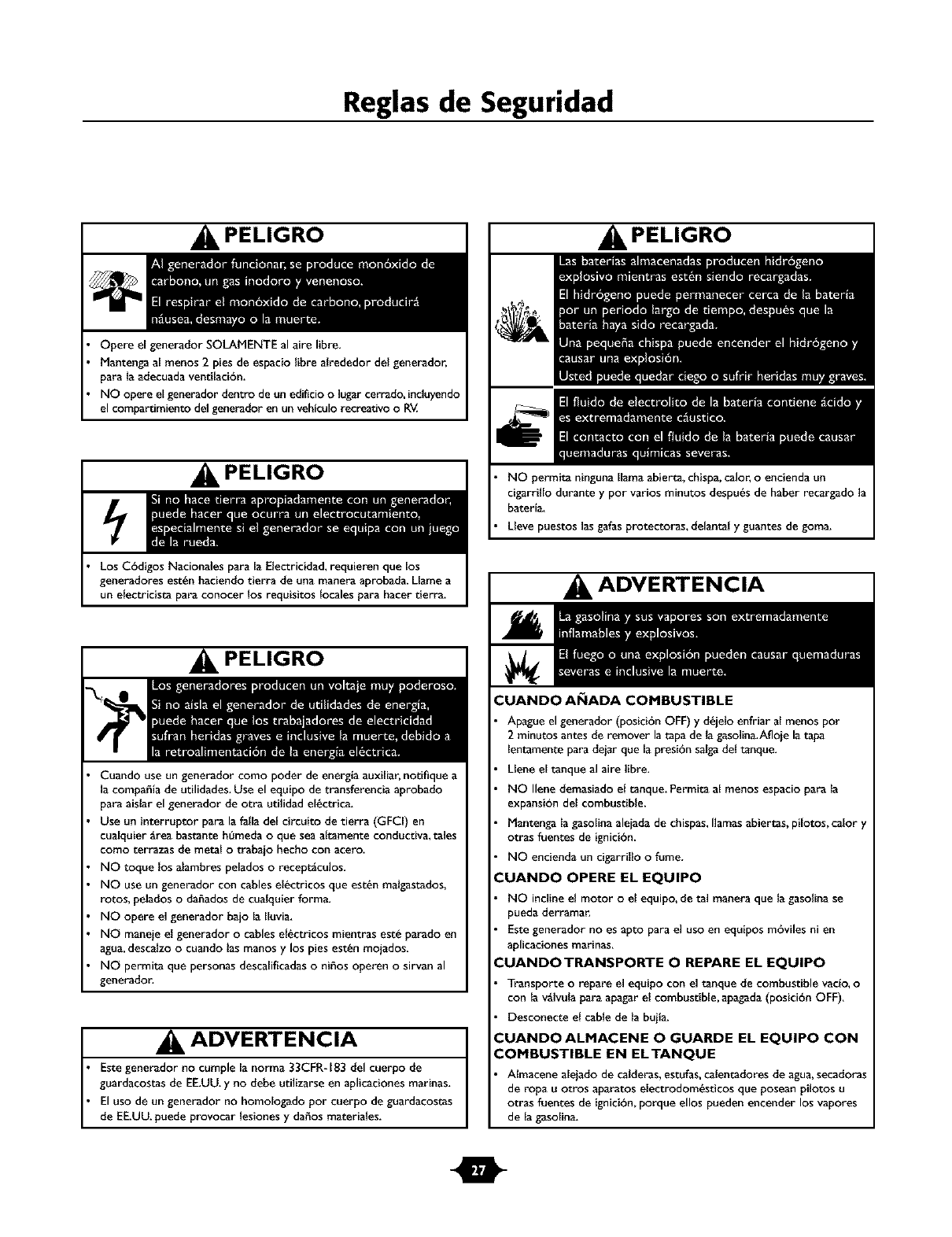
PELIGRO
Opere el generador SOLAMENTE al aire libre.
Mantenga al menos 2 pies de espaciolibre alrededor del generador,
para la adecuada ventilaci6n.
NO opere el generador dentro de un edificio o lugar cerrado, incluyendo
el compartimiento del generador en un vebiculo recreativo o RM
PELIGRO
Los C6digos Nacionales para la Electricidad,requieren que los
generadores est_n haciendo tierra de una manera aprobada. Llame a
un electricista para conocer los requisitos locales para hacer tierra.
PELIGRO
Cuando use un generador como poder de energla auxiliar, notifique a
la compa_ia de utilidades. Use el equipo de transferencia aprobado
para aislar el generador de otra utilidad el6ctrica.
Use un interruptor para la falLadef circuito de tierra (GFCI) en
cualquier grea bastante h_meda oque seaaltamente conductiva, tales
como terrazas de metal o trabajo becho con acero.
NO toque los alambres pelados o receptgculos.
NO use un generador con cablesel_ctricos que est_n malgastados,
rotos, pelados odafiados de cualquier forma.
NO opere el generador bajo la Iluvia.
NO maneie el generador o cables el_ctricos mientras este parado en
agua,descalzo o cuando las manos y los pies est_n mojados.
NO permita que personas descalificadaso ni_os operen o sirvan al
generador.
ADVERTENCIA
Estegenerador no cumple la norma 33CFR-183 del cuerpo de
guardacostas de EE.UU.y no debe utilizarseen aplicaciones marinas.
El usode un generador no homologado pot cuerpo de guardacostas
de EE.UU.puede provocar lesiones y dafios materiales.
PELIGRO
NO permita ninguna llama abierta, chispa, calor, o encienda un
cigarrillo durante y por varios minutos despu6s de haber recargado la
bateria.
Lleve puestos las galas protectoras, delantal y guantes de goma.
ADVERTENCIA
CUANDO AI_IADA COMBUSTIBLE
Apague el generador (posici6n OFF) y d6jelo enfriar al menos pot
2 minutos antes de remover la tapa de la gasolina,Afloje la tapa
lentamente para dejar que la presi6n salga del tanque.
Llene el tanque al aire libre.
NO Ilene demasiado el tanque. Permita al menos espacio para la
e×pansi6n del combustible.
Mantenga la gaso[ina aleiada de chispas, llamas abiertas, pilotos, calor )'
otras fuentes de ignici6n.
NO encienda un cigarrillo o fume.
'_UANDO OPERE EL EQUIPO
NO incline el motor o el equipo, de tal manera que la gasolina se
pueda derramar,
Este generador no es apto p_ra el uso en equipos m6viles ni en
aplicaciones marinas.
'_UANDOTRANSPORTE OREPARE EL EQUIPO
Transporte o repare el equipo con el tanque de combustible vaclo, o
con la v_Ivula para apagar el combustible, apagada (posiciOn OFF).
Desconecte el cable de la buila.
'_UANDO ALMACENE OGUARDE EL EQUIPO CON
COMBUSTIBLE EN ELTANQUE
Almacene aleiado de calderas, estufas, calentadores de agua, secadoras
de ropa u otros aparatos electrodom_sticos que posean pilotos u
otras fuentes de ignici6n, porque ellos pueden encender los vapores
de la gasolina.
m
Reglas de Seguridad
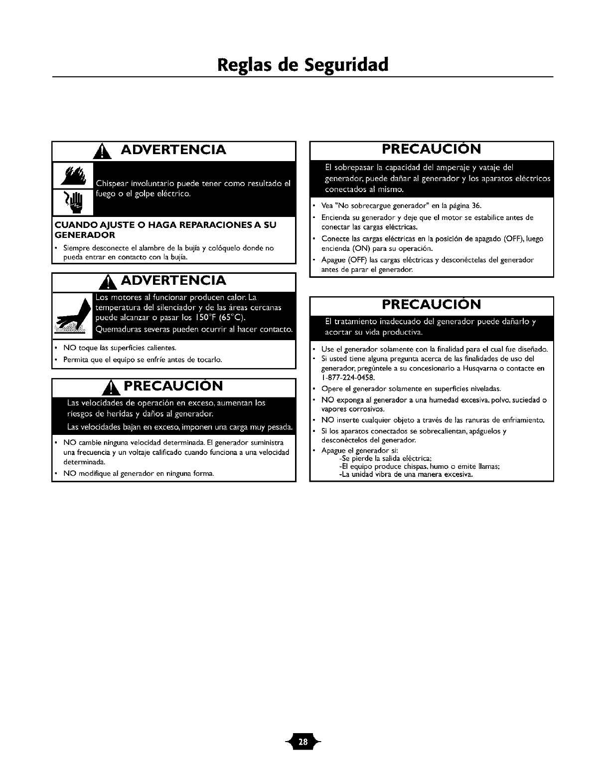
ADVERTENCIA
;ENERADOR
Siempre desconecte el alambre de la bujlay col6quelo donde no
pueda entrar en contacto con la bujla.
ADVERTENCIA
NO toque las superficies calientes,
Permita que el equipo se enfrle antes de tocarlo,
PRECAUCION
NO cambie ninguna velocidad determinada. El generador suministra
una frecuencia y un voltaje calificado cuando funciona a una velocidad
determinada.
NO modifique al generador en ninguna forma.
PRECAUCION
Vea "No sobrecargue generador" en la p_gina36.
Encienda su generador y deje que el motor se estabilice antes de
conectar lascargas el/actricas,
Conecte las cargas el_ctricas en la posici6n de apagado (OFF), luego
encienda (ON) para su operaci6n.
Apague (OFF) las cargasel_ctricas y desconSctelas del generador
antes de parar el generador.
PRECAUCION
Use el generador solamente con la finalidad para el cual rue diseffado.
Si usted tiene alguna pregunta acerca de lasflnalidades de uso del
generador, preg6ntele a su concesionario a Husqvarna o contacte en
1-877-224-0458,
Opere el generador solamente en superficies nivel_das,
NO exponga al generador a una humedad excesiva,poNo, suciedad o
vaporescorrosivos,
NO inserte cualquier objeto a trav6s de ]asranuras de enfriamiento,
Si los aparatos conectados se sobrecalientan, ap&guelosy
descon_ctelos del generador,
Apague el generador si:
-Se pierde la salida el_ctric_;
-El equipo produce chispas,humo o emite llamas;
-La unidad vibra de una manera excesiva.
O
Caracteristicas ¥ Controles
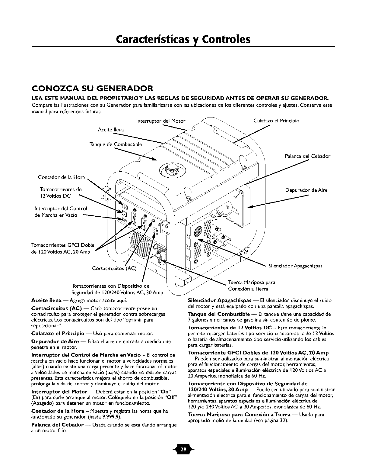
CONOZCA SU GENERADOR
LEA ESTE MANUAL DEL PROPIETARIOY LAS REGLAS DE SEGURIDAD ANTES DE OPERAR SU GENERADOR.
Compare las ilustracionescon su Generador para familiarizarse con las ubicaciones de los diferentes controles y ajustes. Conserve este
manual para referencias futuras.
Interruptor del Motor Culatazo el Principio
Aceite Ilena
Contador de la Hora
Tomacorrientes de
12Voltios DC
Interruptor del Control
de Marcha enVacfo
Tanque de Combustible
Palancadel Cebador
Depurador deAire
Tomacorrientes GFCI Doble
de 120Voltios AC, 20 Amp
Cortacircuitos (AC)
Tomacorrientes con Dispositivo de
Seguridad de 120/240Voltios AC, 30Amp
Aceite Ilena --Agrega motor aceite aqui.
Cortacireuitos (AC) -- Cada tomacorriente posee un
cortacircuito para proteger el generador contra sobrecargas
el6ctricas. Los cortacircuitos son del tipo "oprimir para
reposicionar".
Culatazo el Principio -- Us6 para comenzar motor.
Depurador deAire -- Filtra el aire de entrada a medida que
penetra en el motor.
Interruptor del Control de Marcha enVacio -El control de
marcha en vacio hace funcionar el motor a velocidades normales
(altas) cuando existe una cargapresente y hace funcionar el motor
a velocidades de marcha en vacio (baias)cuando no existen cargas
presentes. Estacaracterfstica mejora el ahorro de combustible,
prolonga la vida del motor y disminuye el ruido del motor.
Interruptor del Motor -- Deber_ estar en la posicibn "On"
(En) para darle arranque al motor. Colbquelo en la posici6n "Oft"
(Apagado) para detener un motor en funcionamiento.
Contador de la Nora -Muestra y registra las horas que ha
funcionado su generador (hasta 9,999.9).
Palanca del Cebador -- Us_dacuando se est_ dando arranque
a un motor frio.
Silenciador Apagachispas
Tuerca Mariposa para
Conexibn a Tierra
Silenciador Apagachispas -- El silenciador disminuye el ruido
del motor y est_ equipadocon una pantalla apagachispas.
Tanque del Combustible -- El tanque tiene unacapacidadde
7 galones americanos de gasolinasin contenido de plomo.
Tomacorrientes de 12Voltios DC - Este tomacorriente le
permite recargar baterlas tipo servicio oautomotriz de 12Voltios
o bateria de almacenamiento tipo servicio utilizando los cables
para cargar baterias.
Tomacorriente GFCl Dobles de 120Voltios AC, 20 Amp
-- Pueden ser utilizadospara suministrar alimentaci6n el6ctrica
para el funcionamiento de cargasdel motor, herramientas,
aparatos especialese iluminaci6nel6ctrica de 120Voltios AC a
20Amperios, monof_sica de 60 Hz.
Tomacorriente con Dispositivo de Seguridad de
120/240 Voltios, 30 Amp -- Puedeser utilizadopara suministrar
alimentacibn el6ctrica para el funcionamiento de cargasdel motor,
herramientas, aparatos especialese iluminacibnel6ctrica de
120 y/o 240 Voltios AC a 30 Amperios, monof_sica de 60 Hz.
Tuerca Mariposa para Conexi6n aTierra -- Usado para
apropiado moll6 de la unidad (vea p_gina 32).
m
Montaje
MONTAJE
Sugenerador requiere de ciertos procedimientos de montaie y
solo estar6 listo para ser utilizado despu_s de haberle
suministrado servicio con el combustible y aceite recomendados.
Si usted tiene problemas con el montaje de su generador,
pot favor Ilame a la linea de ayuda para generadores al
1-877-224-0458.
Para Retirar el Generador de la Caja
I. Coloque la caia sobre una superficie plana y rigida, con las
flechasque dicen "this side up" hacia arriba.
2. Abra con cuidado las tapas superiores de la caia de envto.
3. Corte de arriba a abaio las esquinasde uno de los lados de
la caja y coloque ese lado de la cajasobre el suelo.
4. Retire todo el material de empaque, relleno, etc.
5. Saqueel generador de la caja de envio.
Contenido De La Caja
Revisetodo el contenido. Si algunade las partesno est_ presente
oest_ da_ada,por favor Ilame a la linea de ayuda para
generadores al 1-877-224-0458.
La unidad principal
Manual del propietario y motor
Aceite para motor
Cables para cargar baterias
Tapones de fijaci6n
Juegode ruedas
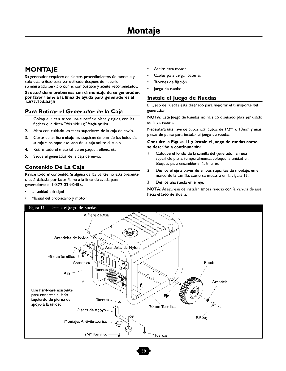
Instale el Juego de Ruedas
El }uego de ruedas est_ dise_ado para mejorar el transporte del
generador.
NOTA: EsteJuegode Ruedasno ha sido dise_ado para ser usado
en la carretera.
Necesitar_ una Ilavede cubos con cubos de I/2"" o13mmy unas
pinsasde punta para instalarel juego de ruedas.
Consulte la Figura I I y instale el juego de ruedas como
se describe a continuaci6n:
I. Coloque el fondo de la camilla del generador en una
superficie plana.Temporalmente, coloque la unidad en
bloques para ensamblarla f_cilmente.
2. Deslice el eje a trav_s de ambos soportes de montaje, en el
marco de la camilla,como se muestra en la Figura I I.
3. Deslice una rueda en el eie.
NOTA: Aseg_rese de instalarambas ruedas con la v_lvula de aire
hacia el lado de afuera.
Alfilere de Asa
Arandelas de Nylon
45
Arandelas
Asa _
_Arandelas de Nylon
Use hardware existente
para conectar el lado
izquierdode pierna de
apoyo a la unidad
Tuercas
Pierna de A
Montajes Antivibratorios
Rueda
Arandela
Eie
20 mmTornillos
/
E-Ring
-Tuercas
m
Montaje
4. Coloque el e-ring en la ranura del eje.
5. Coloque un extremo de las pinzas de puntas de agujaen la
parte inferior del eje y el otro extremo de las pinzas en la
parte superior del e-ring.Asiente el e-ring cerrando las
pinzas.
6. Repita los pasos 3 por 5 para asegurar la segunda rueda.
7. Remuevalos bloques temporales.
8. tnsta[e los montaies antivibratorios a [a pata de soporte
uti[izando dos tornil[os prisioneros 3/4" tuercas de seguridad.
9. Para ayudar al ensamblajede la pata de apoyo, hagadescansar
el generador en la camilla, con la parte del motor hacia abajo.
Quite e[ hardware existente de[ monte izquierdo de la
vibraci6n de la unidad con 13mm [laveinglesa.Use el mismo
hardware para conectar la pierna de apoyo.
10. Conecte el otro [ado de [a pierna de apoyo con un 20 mm
tornillo de la tapa y nuez de cerradura. Descanse el
generador en la pierna de ruedas y apoyo.
I I. Fije el asaspara maneiar par_ntesis en el marco del
generador, como se muestra en la Figura I I. Parael[o utilice
un 45 mm torni[Ios, arandelas,arande[as de nylon y una
tuerc_.
12. Serpentee alfileres de asa al marco del generador como
mostrado en la Figura I I. Suba el asa e inserte su pasador
para mover el generador.
13. Verifique que todas las piezasest_n apretadas y lasIlantas
est_n infladascon aire entre 15-40 PSI.
ANTES DE DARLE ARRANQUE AL
MOTOR
Agregar Aceite al Motor y Gasolina
Coloque lagenerador sobre una superficie nivelada.
PRECAUCI( N
•Consulte el manual de] propietario del motor para afiadir al motor
el aceite y e[ combustible recomendado
•El dafio a [a lavadora a presi6n, resu[tado de la desatencibn a
esta precaucibn, no ser_ cubierto por ]a garantta.
Consulte el manual del propietario del motor para afiadir al
motor el aceite y e[ combustible recomendado.
NOTA: Verifique e[ aceite de[ motor de manera frecuente cuando
_ste se esfuerce demasiado. Consulte el manual de[ propietario
de[ motor para conocer curies son las recomendaciones al
respecto.
NOTA: El campo giratorio del generador se encuentra en un
coiinete pre-lubricado y sel[ado que no requiere lubricaci6n
adiciona[ por la vida 6til de[ cojinete,
t
Operaci6n
CONEXION ATIERRA DEL
GENERADOR
El Cbdigo Nacional de Electricidad exige que el marco y las
partes exteriores del generador conductoras de electricidad,
est6n conectadas a tierra adecuadamente. Los c6digos el_ctricos
locales tambi_n pueden exigir que la unidad est_ conectada a
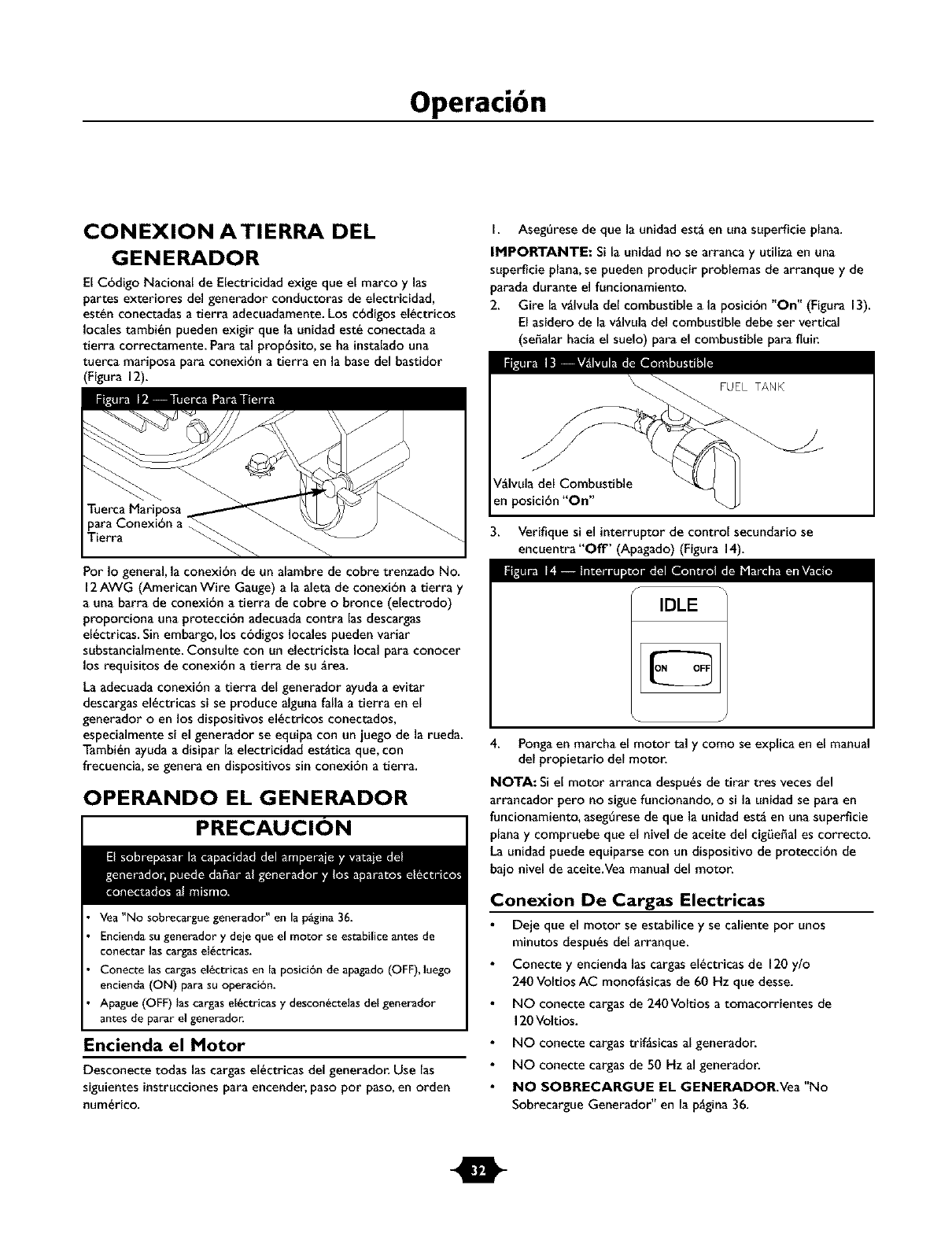
tierra correctamente. Para tal prop6sito, se ha instalado una
tuerca mariposa para conexi6n a tierra en la base del bastidor
(Figura 12).
Tuerca Mariposa
para Conexi6n a
Tierra
la_l IEI _,_Tmj._'_l_l [_l S_ li_l_ll_Wl'Av._lPor Io general, la conexi6n de un alambre de cobre trenzado No.
12AWG (AmericanWire Gauge) a la aleta de conexi6n a tierra y
a una barra de conexi6n a tierra de cobre o bronce (electrodo)
proporciona una protecci6n adecuada contra las descargas
el_ctricas. Sin embargo, los c6digos locales pueden variar
substancialmente. Consulte con un eleetricista local para conocer
los requisitos de conexi6n a tierra de su _,rea.
La adecuada conexi6n a tierra del generador ayudaa evitar
descargasel_ctricas si se produce alguna falla a tierra en el
generador o en los dispositivos el_ctricos conectados,
especialmente si el generador se equipa con un juego de la rueda.
Tambi_n ayudaa disipar la electricidad est_tica que, con
frecuencia, se genera en dispositivos sin conexi6n a tierra.
OPERANDO EL GENERADOR
PRECAUCION
Vea "No sobrecargue generador" en la p_gina 36.
Enciendasu generador y deje que el motor se estabilice antes de
conectar las cargasel_ctricas.
Conecte las cargas el_tricas en la posiciOn de apagado (OFF), luego
encienda (ON) para su operaci6n.
Apague (OFF) las cargas el_ctricas y descon_ctelas del generador
antes de parar el generador.
Encienda el Motor
Desconecte todas las cargas el_ctricas del generador. Use las
siguientes instrucciones para encender, paso por paso, en orden
num_rico.
I. Aseg_rese de que la unidad est_ en una superflcie plana.
IMPORTANTE: Si la unidad no se arranca y utiliza en una
superficie plana, se pueden producir problemas de arranque y de
parada durante el funcionamiento.
2. Gire la v_Ivula del combustible a la posici6n "On" (Figura 13).
El asidero de la v_Ivula del combustible debe ser vertical
(seffalar hacia el suelo) para el combustible para fluir.
V_Ivula del Combustible
en posici6n "On"
3. Verifique si el interruptor de control secundario se
encuentra"Off' (Apagado) (Figura 14).
IDLE
4. Pongaen marcha el motor tal y como se explica en el manual
del propietario del motor.
NOTA: Siel motor arranca despu_s de tirar tres veces del
arrancador pero no siguefuncionando, o si la unidad se para en
funcionamiento, aseg_rese de que la unidad est_ en una superficie
plana y compruebe que el nivel de aceite del cigLieffales correcto.
La unidad puede equiparse con un dispositivo de protecci6n de
bajo nivel de aceite.Vea manual del motor.
Conexion De Cargas Electricas
Deje que el motor se estabilice y se caliente pot unos
minutos despu_s del arranque.
Conecte y encienda las cargas el_ctricas de 120 ylo
240 Voltios AC monof_sicas de 60 Hz que desse.
NO conecte cargas de 240Voltios a tomacorrientes de
120 Voltios.
NO conecte cargas trif_sicas al generador.
NO conecte cargas de 50 Hz al generador.
NO SOBRECARGUE EL GENERADOR.Vea "No
Sobrecargue Generador" en la p_gina 36.
I
Operaci6n
Parado Del Motor
1. Desconecte todas las cargase{_ctricas de {os tomaco-
rrientes del panel del generador. NUNCA de arranque o
detenga el motor con todos los dispositivos el_ctricos
conectados y encendidos.
2. Verifique si el interruptor de control secundario se
encuentra "Off' (Apagado).
3. Oeje que el motor funcione sin cargaspor algunos minutos
para estabilizar las temperaturas internasdel motor y el
generador.
4. Pour _teindre le moteur, suivez les instructionsqui figurent
darts le manuel d'utilisation.
5. Cierre la v_lvula del combustible.
FUNCIONAMIENTO DEL
CONTROL AUTOMATICO DE
MARCHA EN VACIO
Este interruptor ha sido disefado para mejorar el consumo de
combustible. Cuando _ste interruptor sea "Activado", el motor
funcionar_ _nicamente en su alta velocidad de mando normal una
vez sea conectadauna cargael_ctrica. Cuando lacarga el_ctrica es
retirada, el motor funcionar_ a una velocidad meno_:Siel
interruptor est_"Desactivado", el motor funcionar_ en alta
velocidad normal. Siempre tenga el interruptor en la posici6n
"Off" (apagado) cuando arranque y detenga el motor.
PROCEDIMIENTO DE CARGA DE
LA BATERIA
Sugenerador tiene la capacidad de recargar baterias descargadas
de acumuladores tipo servicio oautomotriz de 12Voltios. NO
utilice la unidad para cargar batertas de 6 Voltios. NO use la unidad
)ara mover motores que tengan la baterta descargada.
PELIGRO
NO permita ninguna llamaabierta,chispa_caior,oenciendaun cigarriilo
durante y pot varios minutos despu_sde haber recargado la bater_a.
Lleve puestos lasgalas protectoras, deIantat y guantes de goma.
Para recargar baterias de 12Voltios, Ileve a cabo los
siguientes procedimientos:
Revise el nivel del liquido en todas las celdas de la baterla. Si
es necesario, afada aguadestilada UNiCAMENTE hasta
cubrir los separadores de las celdas de la baterla. NO use
agua de grifo.
Si la baterta esrAequipada con tapas de desfogue,aseg_rese
de que est_n instaladasy apretadas.
Limpie los terminales de la baterta si es necesario.
Conecte el enchufe conector del cable de cargade la bateria
al tomacorrientes del panel identificadocon las palabras
"12-VOLTS D.C." (" 12-VOLTIOS D.C.").
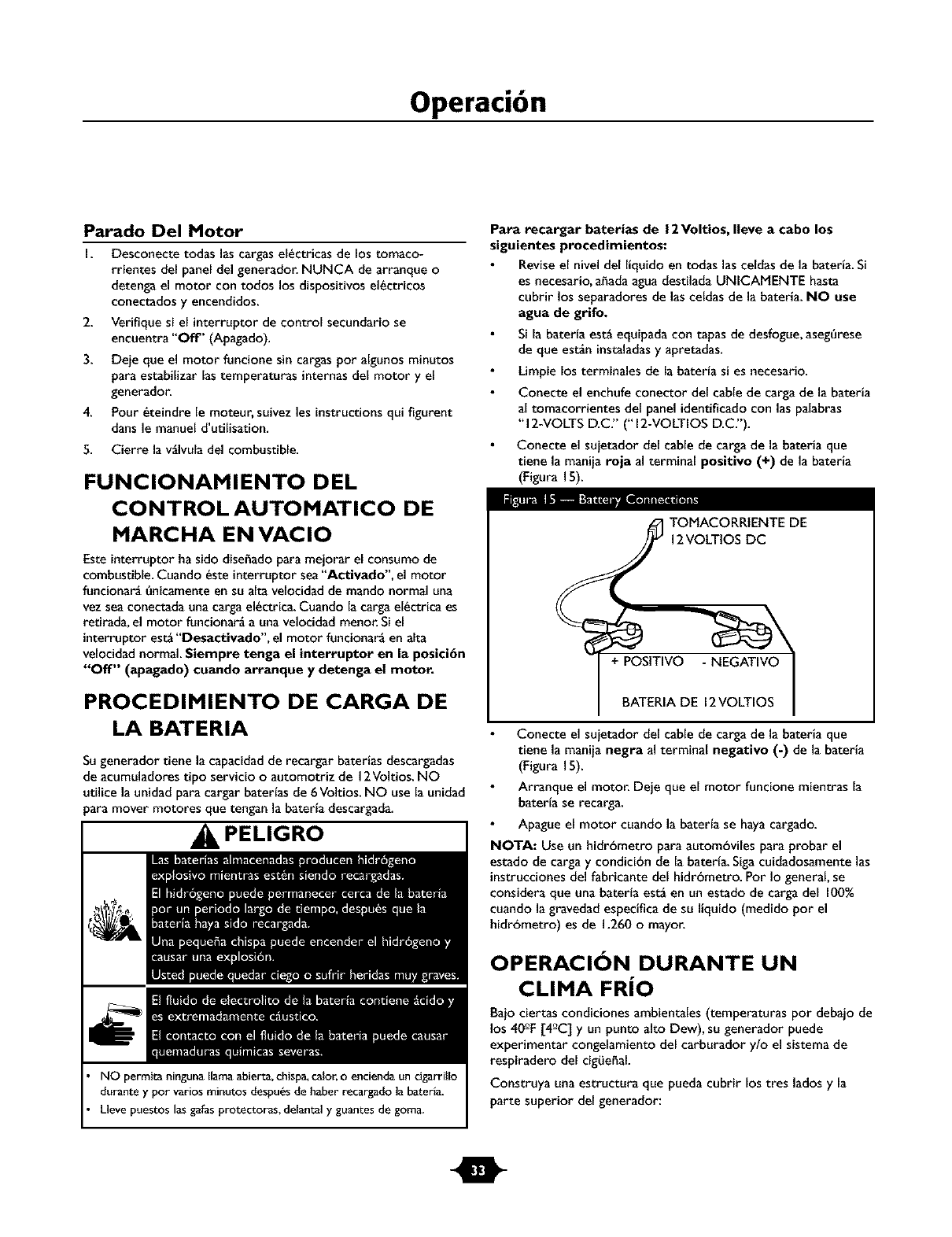
Conecte el suietador del cable de cargade la bateria que
tiene la maniia roja al terminal positivo (+) de la bateria
(Figura 15).
TOMACORRIENTE DE
12VOLTIOS DC
+ POSITIVO - NEGATIVO
BATERIA DE 12VOLTIOS
Conecte el suietador del cable de cargade la bateria que
tiene la maniia negra al terminal negativo (-) de la bateria
(Figura 15).
Arranque el motor. Deje que el motor funcione mientras la
baterta se recarga.
Apague el motor cuando la baterta se hayacargado.
NOTA: Use un hidrc3metro para automc3vilespara probar el
estado de carga y condicibn de la baterta. Sigacuidadosamente las
instruccionesdel fabricante del hidrbmetro. Por Io general, se
considera que una baterta est_ en un estado de carga del I00%
cuando la gravedad especifica de su liquido (medido por el
hidrc3metro) es de 1.260omayor.
OPERACION DURANTE UN
CLIMA FRiO
Baio ciertas condiciones ambientales (temperaturas pot debajo de
los 40_F[4_C] y un punto alto Dew), su generador puede
experimentar congelamiento del carburador y/o el sistema de
respiradero del cigLiefal.
Construya una estructura que pueda cubrir los tres lados y la
parte superior del generador:
m
Operaci6n
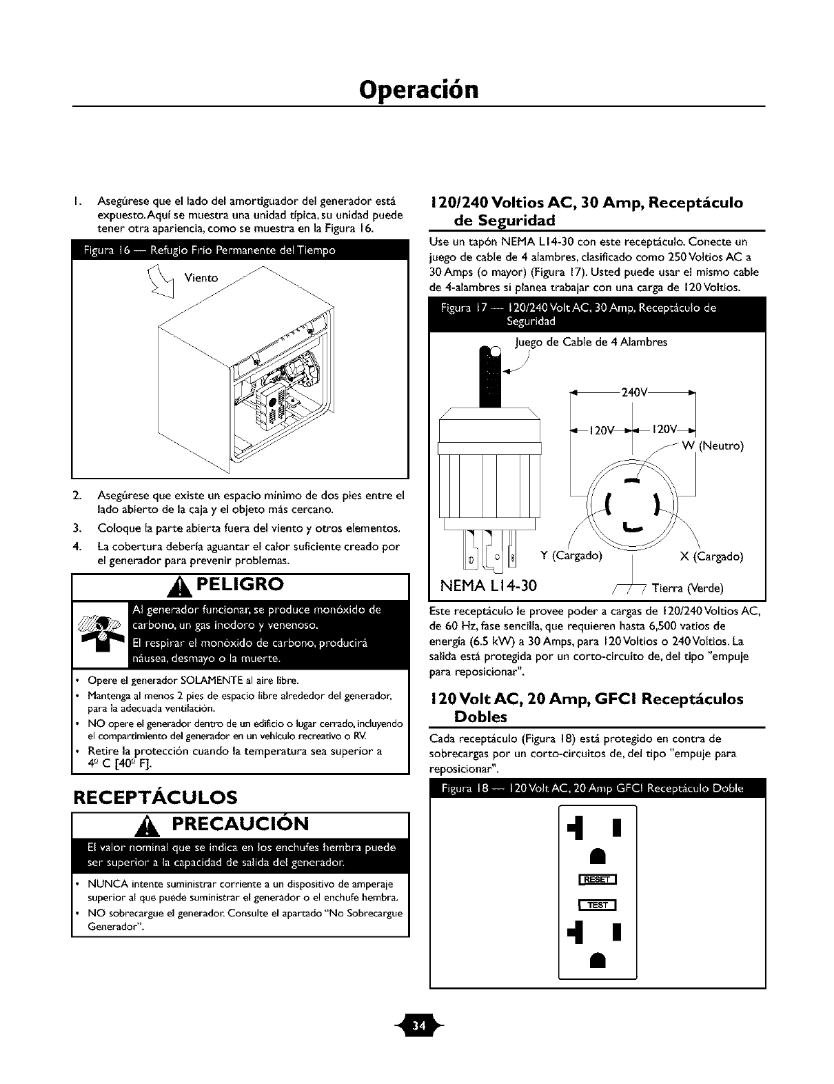
I. Aseg_rese que el lado del amortiguador del generador est_
expuesto.Aquf se muestra una unidad tfpica,su unidad puede
tener otra apariencia,como se muestra en la Figura 16.
2. Aseg_rese que existe un espaciominimo de dos piesentre el
lado abierto de la caja y el obieto m_s cercano.
3. Coloque la parte abierta fuera del viento y otros elementos.
4. La cobertura deberfa aguantar el calor suflciente creado por
el generador para prevenir problemas.
PELIGRO
Opere el generador SOLAMENTE al aire libre,
Manteng_ al menos 2 pies de espacio libre _lrededor del generador,
p_ra la adecuada ventilaci6n.
NO opere el generador dentro de un edificio o lug_r cerrado, incluyendo
el compartimiento del generador en un vehiculo recreatJvoo R_
Retire la proteccibn cuando la temperatura sea superior a
4 °_C [40 °_F].
RECEPTACULOS
PRECAUCION
NUNCA intente suministrar corriente a un dispositivode amperaje
superior al que puede suministrar el generador o el enchufe hembra.
NO sobrecargue el generador. Consulte el apartado"No Sobrecargue
Generador".
120/240 Voltios AC, 30 Amp, Recept_culo
de Seguridad
Use un tap6n NEMA LI4-30 con este recept_culo. Conecte un
juego de cable de 4 alambres,clasificado como 250 Voltios AC a
30Amps (o mayor) (Figura 17).Usted puede usar el mismo cable
de 4-alambres si planea trabaiar con una carga de 120Voltios.
Juego de Cable de 4 Alambres
(Neutro)
Y (Cargado) X (Cargado)
NEMA L14-30 Tierra (Verde)
Este recept_culo le provee poder a cargas de 120/240Voltios AC,
de 60 Hz, fase sencilla,que requieren hasta 6,500 vatios de
energla (6.5 kW) a 30Amps, para 120Voltios o240Voltios. La
salidaest_ protegida por un corto-circuito de, del tipo "empuje
para reposicionar".
120 Volt AC, 20 Amp, GFCI Recept_culos
Dobles
Cada recept_culo (Figura 18) est_ protegido en contra de
sobrecargas por un corto-circuitos de, del tipo "empuje para
reposicionar".
4n
m
Operaci6n
Use cada recept_culo para operar 120Voltios AC, de fase sencilla,
de cargasde 60Hz que requieren hasta 2,400 vatios (2.4 kW) a
corrientes de 20Amps. Use los juegos de cables que son
calificados para cargas de 125Voltios AC, a 20 Amps (o mayores).
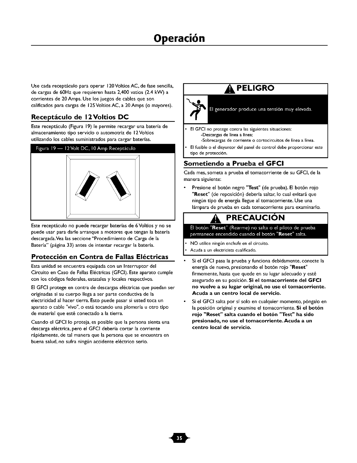
Recept_culo de 12Voltios DC
Esterecept_culo (Figura 19) le permite recargar una bateria de
almacenamiento tipo servicio oautomotriz de 12Voltios
utilizando los cables suministrados para cargar baterfas.
Esterecept_culo no puede recargar baterfas de 6Voltios y no se
puede usar para darle arranque a motores que tengan la baterfa
descargada.Vealas seccione "Procedimientode Carga de la
Baterfa" (p_gina 33) antes de intentar recargar la baterfa.
Protecci6n en Contra de Fallas El_ctricas
Esta unidad se encuentra equipada con un lnterruptor del
Circuito en Caso de FallasEl_ctricas(GFCI). Este aparato cumple
con los cbdigos federales,estatales y locales respectivos.
El GFCI protege en contra de descargasel_ctricas que puedan ser
originadas si su cuerpo Ilega a ser parte conductiva de la
electricidad al hacer tierra. Esto puede pasar si usted toca un
aparato o cable "vivo", o est_ tocando una plomerta u otro tipo
de material que est_ conectado a la tierra.
Cuando el GFCI Io proteja, es posible que la persona sienta una
descargael_ctrica, pero el GFCI deberla cortar la corriente
r_pidamente, de tal manera que la persona que se encuentra en
buena salud,no sufra ning_n accidente el_ctrico serio.
PELIGRO
El GFCI no protege contra las siguientes situaciones:
-Descargasde I_neaa I_nea;
-Sobrecargasde corriente o cortocircuitos de llneaallnea.
El fusible o el disyuntor del panel de control debe proporcionar este
tipo de proteccibn.
Sometiendo a Prueba el GFCI
Cada mes,someta a prueba el tomacorriente de su GFCI, de la
manera siguiente:
Presione el botbn negro "Test" (de prueba). El botbn rojo
"Reset" (de reposicibn) deberta saltar, Io cual evitar6 que
ning_n tipo de energla Ilegueal tomacorriente. Use una
Igmpara de prueba en cada tomacorriente para examinarlo.
PRECAUClON
NO utilice ning_n enchufe en el ¢ircuito.
Acuda a un electricista cualific_do.
Si el GFCI pasa la prueba y funciona debidamente,conecte la
energta de nuevo,presionando el botbn roio "Reset"
firmemente, hasta que quede en su lugar adecuado y est_
asegurado en su posicibn. Si el tomacorriente del GFCI
no vuelve asu lugar original, no use el tomacorriente.
Acuda a un centro local de servicio.
Si el GFCI salta por st solo en cualquier momento, pbngalo en
la posicibn original y examine el tomacorriente. Si el bot6n
rojo "Reset" salta cuando el bot6n "Test" ha sido
presionado, no use el tomacorriente.Acuda a un
centro local de servieio.
Q
Operaci6n
NO SOBRECARGUE GENERADOR
Capacidad
Usted debe asegurarse que su generador puede proveer el
suflciente vataie calificado (cuando est6 funcionando) y de carga
(al encender) para los aparatos a los cuales va a proveer la
energia,al mismo tiempo. Sigaestos pasos:
I. Seleccione los aparatos que recibir_n la energia,al mismo
tiempo.
2. Totalice los ratios calificados (cuando est6 funcionando) de
estos aparatos. Esta es la cantidad de energfa que su
generador debe producir para mantener eso aparatos
funcionando adecuadamente.Veala Figura 20.
3. Calcule la cantidad de ratios de carga (al encender) que
usted necesitar_. Elvataie de carga es la cantidad minima de
electricidad, necesaria para encender herramientas o
aparatos con motores el6ctricos, tales como, sierras
circulares orefrigeradores. Debido a que no todos los
motores se encienden al mismo momento, el vataje total de
carga se puede estimar al afiadir solamente el(los) aparato(s)
con el vataje adicional m_salto, al total del vataje califlcado,
obtenido en el paso 2.
Ejemplo:
Herramienta o
Aparato EI6ctrico
Aire Acondicionado
de Venmna
Refrigerador
Congelador industrial
Televisi6n
Luz (75 Vatios)
Vatios Califlcados
(cuando est6
funcionando)
1200
800
5OO
5OO
75
Total=3075
Vatiosparafuncionar
VataieTotal Calificado
Vataie de Carga Adicional m_s alto
SalidaTotal Requerida del Generador
Vatios Adicionales de
Carga (al encender)
1800
1600
5O0
1800 (Vatios de
Carga m_s alto)
:uando est6 funcionando)= 3075
= 1800
= 4875
Control de la Energla
Para prolongar la vidade su generador y los aparatos que est6n
conectados al mismo, es muy importante cuidarlo cuando se le
afiaden cargas el6ctricas. Nada deberia estar conectado a los
tomacorrientes del generador antes de que su motor sea
encendido. Laforma correcta y mgs segura para controlar la
energia del generador, es la de afiadir en secuencias las cargas,
como se describe a continuacibn:
I. Sin tener nada conectado al generador, encienda el motor de
la manera descrita en este manual.
2. Conecte y encienda la primera carga,preferiblemente la
mayor que usted tenga.
3. Permita que la salida del generador se estabilice (el motor
funciona suavemente y el aparato conectado al mismo trabaja
adecuadamente).
4. Conecte y encienda la pr6xima carga.
5. De nuevo,permita que el generador se estabilice.
6. Repita los pasos4 y 5 para cada cargaadicional que usted
tenga.
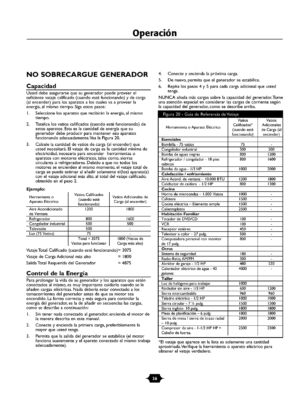
NUNCA afiada m_s cargassobre la capacidad del generador.Tome
una atencibn especial en considerar las cargas de corriente seg6n
capacidaddel generador, como se describe arriba.
Herramienta o Aparato EI6ctrico
Esenciales
Bombilla -75 vatios
Congelador industrial
Bomba de aguas negras
Refrigerador /congelador - 18 pies
cubicos
Bomba de agua-I/3 HP
Calefacci6n /enfriamiento
Aire Acond. de ventana- 10.000 BTU
Calefactor de caldera -I/2 HP
Cocina
Homo de microondas -1.000 Vatios
Cafetera
Cocina el6ctrica - Elementosimple
Calientaplatos
Habitaci6n Familiar
Tocador de DVDICD
VCR
Receptor est6reo
Televisor a color -27 pulg.
Computadora personal con monitor
de 17 pulg.
Otro$
Sistema de se_uridad
Radio-Reloj AM/FM
Abridor de garaie- I/2 HP
Calentador el6ctrico de agua- 40
galones
Taller
Luz de hal6_eno para trabaiar
Rociador sin aire- I/3 tiP
Sierra intercambiable
Taladro el6ctrico - I/2 liP
Sierra circular - 7 ¼ pulg.
Sierra in_lete- I0 pul_.
Mesa de planificaciOn -6 pulg.
Sierra de mesa /sierra de brazo radial
-I0 pulg.
Compresor de aire - I-I/2 lip lip =
Caballo de fuerza.
Vatios
Calificados*
(cuando est6
funcionando)
75
500
8OO
8OO
1000
1200
8OO
1000
1500
1500
2500
100
100
450
500
800
180
300
480
4000
1000
6OO
96O
1000
1500
1800
1800
2000
Vatios
Adicionales
de Carga (al
encender)
500
1200
1600
2000
1800
1300
520
1200
96O
I000
1500
1800
1800
2OOO
2500 2500
*El vataje que aparece en la lista es solamente una cantidad
aproximada.Verifique la herramienta o aparato el6ctrico para
obtener el vataie verdadero.
O
Mantenimiento
ESPECIFICACIONES
Potencia M_xima..................... 8,125Vatios (8.1 kW)
Potencia de Sobretensi6n .............. 6,500Vatios (6.5 kW)
Voltaje Nominal AC ....................... 120/240Voltios
Corriente MLxima a 120Voltios ............... 54.2Amperios
Corriente MLxima a 240 Voltios ............... 27.I Amperios
FrecuenciaNominal ............................... 60Hz
Fase ...................................... Monof_sica
Tanque del Combustible .............. 7 Galones Americanos
Peso que Embarca............................... 205 Ibs.
RECOMENDACIONES GENERALES
DE MANTENIMIENTO
El propietario / operador es responsable por asegurarse de que
todos los trabaios peri6dicos de mantenimiento se Ileven a cabo
adecuadamente;que todos los problemas son resueltos; y que la
unidad se mantiene limpia y adecuadamente almacenada.NUNCA
opere un generador que est6 da_ado odefectuoso.
Mantenimiento del Motor
Consulte el manual del propietario del motor para las
instruccionesde cbmo mantener adecuadamente el motor.
PRECAUCION
Elaceite usado del motor hasido rnostrado al cancer de la piel de la
causa en ciertos animales del laboratorio.
Completamente lavado expuso areas con el jab6n y el agua.
_ ANTENGA FUERA DE ALCANCE DE NIF,IOS. NO
CONTAMtNE. CONSERVE los RECURSOS.VUELVA
ACEtTE USADO A la COLECCION CENTRA.
Mantenimiento del Generador
El mantenimiento del generador consiste en conservar la unidad
limpia y seca.Opere y almacene la unidad en un ambiente limpio y
seco donde no ser_ expuesta al polvo, suciedad,humedad o
vapores corrosivos. Las ranuras del aire de enfriamiento del
generador no deben estar tapadas con nieve,hojas, o cualquier
otro material extrahos. Revisefrecuentemente la limpieza del
generador y limpielo cuando est6 con polvo, sucio, con aceite,
humedad, ocuando otras substanciasextrahas sean visibles en su
superficie exterior.
NOTA: NO recomendamos el uso de manguerasde iardtn para
limpiar el generador. El aguapodrta introducirseen el sistema de
combustible del motor y causar problemas.Adem_s, si el agua se
introduce al generador a trav6s de lasranuras para aire de
enfriamiento, algo del aguaquedar_ retenida en los espaciosvactos
y grietas del aislamiento del devanado del estator y rotor. La
acumulaci6n de agua y suciedaden los devanados internos del
generador disminuir_ eventualmente la resistencia del aislamiento
de estos devanados.
ADVERTENCIA
ENERADOR
Siempre desconecte el alambre de la bujla y col6quelo donde no
pueda entrar en contacto con la bujia.
Para Limpiar el Generador
Utilice un trapo h_medo para limpiar las superficies
exteriores.
PRECAUCION
NO expongaalgeneradora unahumedadexcesiva,polvo,suciedado
vspores corrosivos,
NO insertecualquierobjetoa trav6sde lasranurasdeenfriamiento.
Puede usar un cepillo de cerdas suaves para retirar la suciedad
endurecida, aceite, etc.
Puede usar una m_quina aspiradora para eliminar suciedad y
residuos sueltos.
Puede usar aire a baja presibn (que no exceda los 25 psi) para
eliminar la suciedad. {nspeccione las ranuras para aire de
enfriamiento y la apertura del generadon Estas aperturas
deber_n mantenerse limpias y despejadas.
m
Almacenamiento
ALMACENAMIENTO
El generador deber_ ser encendido al menos una vez cada siete
dfas y deber_ dejarlo funcionar a[ menos durante 30 minutos. Si
no puede hacer esto y debe a[macenar [a unidad por rags de
30 dfas,siga las siguientes instruccionespara preparar su unidad
para almacenamiento.
Almacenando el Generador
Limpie el generador como est_ descrito en ("Para Limpiar el
Generador").
Reviseque las ranuras para el aire de enfriamiento y las
aperturas del generador se encuentren abiertas y despejadas.
_ADVERTENCIA
NO coloque una cubierta encirna de un generador caliente,
Deje que la unidad se enfrle Io suficientemente antes de que [e
coloque la cubierta.
Almacenando el Motor
Consulte el manual del propietario del motor para las
instrucciones de c6mo preparar adecuadamente el motor para su
almacenamiento.
Otras Sugerencias Para el Almacenando
Para prevenir que se forme una resina en el sistema de
combustible o en partes esencialesdel carburador, vacie
estabilizadores del combustible, suministrados, en el tanque de
gasolinay Ilene con gasolina fresca.Haga funcionar la unidad
por algunos minutos para hacer circular el aditivo a tray,s del
carburador. La unidad y el combustible pueden ser
almacenados hasta por 24 meses.Se puede comprar mgs
estabilizador del combustible, en su tienda local.
NO almacene gasolina de una estaci6n a otra estaci6n,al
menos que haya sido tratada como se mencion6 antes.
Reemplace la caneca de gasolina si comienza a oxidarse. El
6xido y/o la suciedad en la gasolina le causar_ problemas.
Almacene la unidad en un _rea limpia y seca.
O
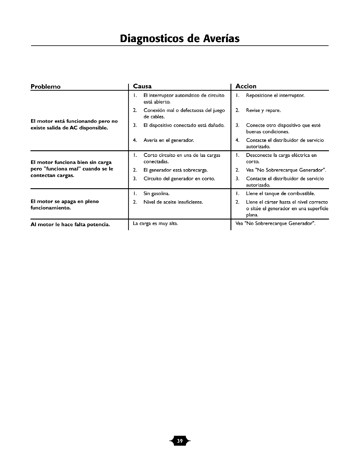
Diagnosticos de Averias
Problemo
El motor est_ funcionando pero no
existe salida de AC disponsible.
El motor funciona bien sin carga
pero "funciona ma|" cuando se le
contectan cargas.
Causa
I. El interruptor autom_tico de circuito
est_ abierto.
2. Conexi6n real o defectuosa del juego
de cables.
3. El dispositivo conectado est_ daffado.
4. Averia en el generador.
I. Corto circuito en una de las cargas
conectadas.
2. El generador est_ sobrecarga.
3. Circuito del generador en corto.
I. Sin gasolina.
El motor se apaga en pleno 2. Nivel de aceite insuficiente.
funcionamiento.
AI motor le hace falta potencia. La carga es muy alta.
Accion
I. Reposicione el interruptor.
2. Revisey repare.
3. Conecte otro dispositivo que est_
buenas condiciones.
4. Contacte el distribuidor de servicio
autorizado.
I. Desconecte la carga el_ctrica en
corto.
2. Vea "No Sobrerecarque Generador".
3. Contacte el distribuidor de servicio
autorizado.
I. Llene el tanque de combustible.
2. Llene el cgrter hasta el nivel correcto
o sit_e el generador en una superficie
plana.
Vea "No Sobrerecarque Generador".
m
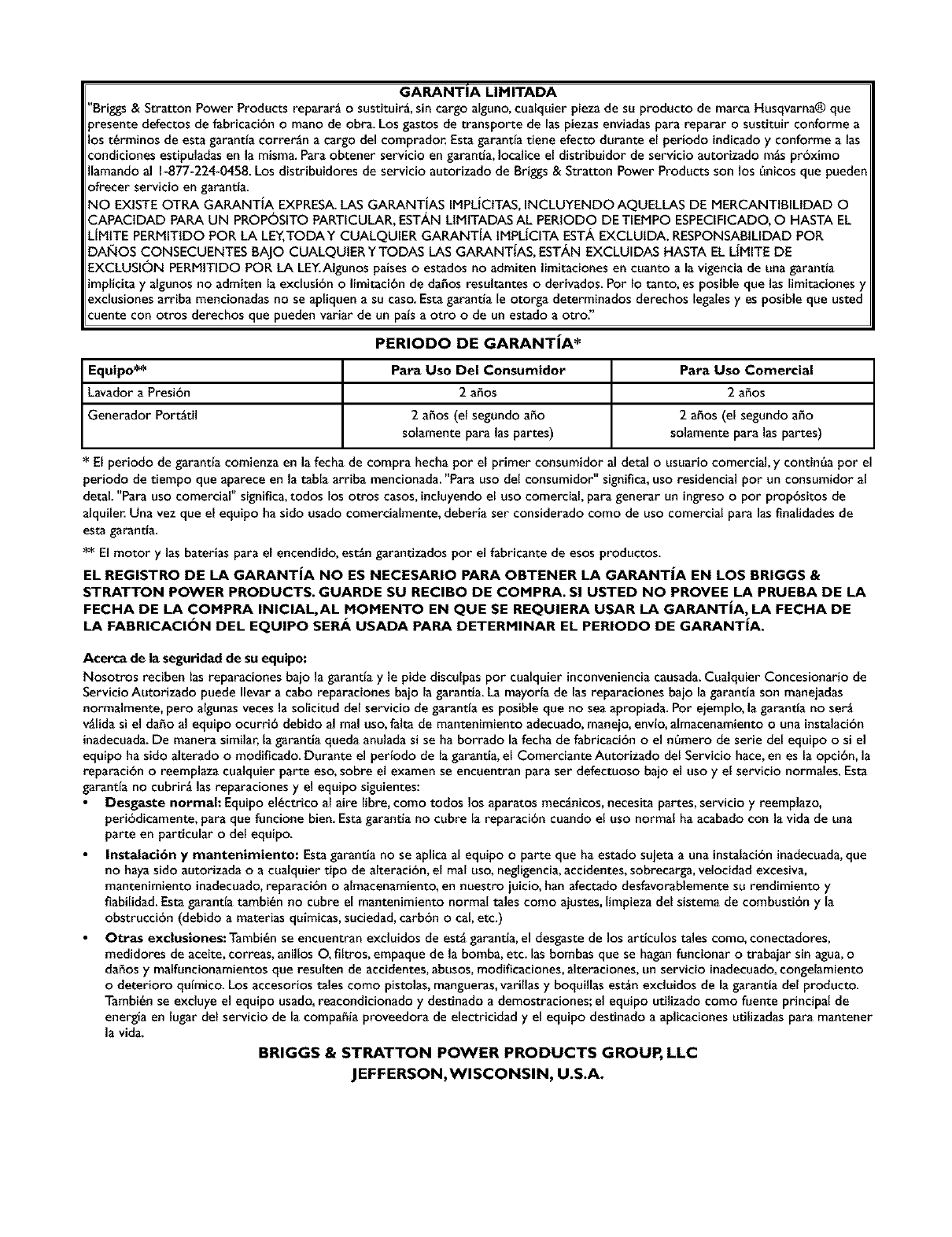
GARANTIA LIMITADA
"Briggs & Stratton Power Products reparar_ osustituir_, sin cargo alguno,cualquier pieza de su producto de marca Husqvarna® que
_resente defectos de fabricacibn omano de obra. Los gastos de transporte de las piezas enviadaspara reparar o sustituir conforme a
os t_rminos de esta garantta correr_n a cargo del comprador. Estagarantta tiene efecto durante el periodo indicadoy conforme alas
condiciones estipuladas en la misma. Paraobtener servicio en garantia, Iocalice el distribuidor de servicio autorizado m_s pr6ximo
Ilamando al b877-224-0458. Los distribuidores de servicio autorizado de Briggs & Stratton Power Products son los 6nicosque pueden
ofrecer servicio en garantta.
NO EXISTEOTRA GARANTJA EXPRESA.LAS GARANTJAS IMPLJCtTAS,INCLUYENDO AQUELLAS DE MERCANTtBILtDAD O
CAPACIDAD PAPA UN PROPOSITO PARTICULAR, EST,_N LtMtTADAS AL PERIODO DETIEMPO ESPECIFICADO,O HASTA EL
LJMITE PERMITtDO POR LA LEY,TODAY CUALQUIER GAPANTJA tMPLJCITA EST,g, EXCLUIDA. RESPONSABtLIDAD POR
DAIKiOS CONSECUENTES BAJO CUALQUtERYTODAS LAS GAPANTiAS, EST,_,NEXCLUIDAS HASTA EL LiMITE DE
EXCLUSION PERMITIDO POR LA LE'KAIgunos paiseso estados no admiten limitaciones en cuanto a la vigencia de una garantta
implicitay algunos no admiten la exclusi6n o limitacibn de da_os resultantes o derivados.Pot Io tanto, es posible que las limitaciones y
exclusiones arriba mencionadas no se apliquen a su caso.Estagarantia le otorga determinados derechos legalesyes posible que usted
cuente con otros derechos que pueden variar de un patsa otro ode un estado a otro"
PERIODO DE GARANT|A*
Equipo** Para Uso Del Consumidor
Lavador a Presibn 2 ahos
Generador PortStil 2 a_os (el segundo a_o
solamente para las partes)
* El periodo de garantta comienza en la fecha de compra hecha pot el primer consumidor
Para Uso Comercial
2 ahos
2 a5os (el segundo a5o
solamente para las partes)
detal o usuario comercial, y contin6a por el
periodo de tiempo que aparece en la tabla arriba mencionada. "Para uso del consumidor" significa, uso residencial por un consumidor al
detal. "Para uso comercial" significa, todos los otros casos, incluyendo el uso comercial, para generar un ingreso o por prop6sitos de
alquilen Una vez que el equipo ha sido usado comercialmente, deberia ser considerado como de uso comercial para las finalidades de
esta garantta.
** El motor y las baterias para el encendido, estSn garantizados por el fabricante de esos productos.
EL REGISTRO DE LA GARANTiA NO ES NECESARIO PARA OBTENER LA GARANTiA EN LOS BRIGGS &
STRATTON POWER PRODUCTS. GUARDE SU RECIBO DE COMPRA. SI USTED NO PROVEE LA PRUEBA DE LA
FECHA DE LA COMPRA INICIAL, AL MOMENTO EN QUE SE REQUIERA USAR LA GARANTIA, LA FECHA DE
LA FABRICACI_)N DEL EQUIPO SERA USADA PAPA DETERMINAR EL PERIODO DE GARANTIA.
Acerca de la seguridad de suequipo:
Nosotros reciben las reparaciones bajo la garantta y le pide disculpas pot cualquier inconvenienciacausada.Cualquier Concesionario de
Servicio Autorizado puede Ilevar a cabo reparaciones bajo la garantia. La mayorfa de las reparaciones bajo la garantia son maneiadas
normalmente, pero algunasveces la solicitud del servicio de garantta es posible que no seaapropiada. Por ejemplo, la garantta no ser_i
vglida si el daho al equipo ocurri6 debido al mal uso,falta de mantenimiento adecuado,maneio, envto, almacenamiento ouna instalacibn
inadecuada.De manera similar, lagarantia queda anulada si se ha borrado la fecha de fabricacibn oel n_mero de serie del equipo osi el
equipo ha sido alterado o modificado. Durante el pertodo de lagarantia, el Comerciante Autorizado del Servicio hace,en es la opcibn, la
reparacibn o reemplaza cualquier parte eso, sobre el examen se encuentran para ser defectuoso bajo el uso y el servicio normales. Esta
garantta no cubrirg las reparaciones y el equipo siguientes:
Desgaste normal: Equipo el_ctrico al aire libre, como todos los aparatos mec_nicos,necesita partes, servicio y reemplazo,
peribdicamente, para que funcione bien. Estagarantia no cubre la reparacibn cuando el uso normal ha acabado con la vida de una
parte en particular odel equipo.
Instalacibn y mantenimiento: Estagarantia no se aplica al equipo oparte que haestado sujeta a una instalacibninadecuada,que
no hayasido autorizada oa cualquier tipo de alteracibn, el real uso, negligencia,accidentes, sobrecarga,velocidad excesiva,
mantenimiento inadecuado,reparacibn o almacenamiento,en nuestro juicio, han afectado desfavorablemente su rendimiento y
fiabilidad. Estagarantta tambi_n no cubre el mantenimiento normal tales como aiustes,limpieza del sistema de combustibn y la
obstruccibn (debido a materias quimicas, suciedad,carbbn ocal, etc.)
Otras exclusiones: Tambi_n se encuentran excluidos de est5 garantta, el desgastede los articulos tales como, conectadores,
medidores de aceite, correas, anillos O, flltros, empaque de la bomba, etc. las bombas que se haganfuncionar o trabajar sin agua,o
dahos y malfuncionamientos que resulten de accidentes, abusos,modificaciones, alteraciones, un servicio inadecuado,congelamiento
odeterioro qutmico. Los accesorios tales como pistolas, mangueras,varillas y boquillas escin excluidos de la garantia del producto.
Tambi_n se excluye el equipo usado,reacondicionado y destinado a demostraciones; el equipo utilizado como fuente principal de
energia en lugar deI servicio de la compahia proveedora de electricidad y el equipo destinado a aplicaciones utilizadas para mantener
la vida.
BRIGGS & STRATTON POWER PRODUCTS GROUP, LLC
JEFFERSON,WISCONSIN, U.S.A.
