Bright Star Engineering MPOD2-C Automotive Diagnostic Scan Tool User Manual microPOD II UserGuide 09 24 12
Bright Star Engineering, Inc. Automotive Diagnostic Scan Tool microPOD II UserGuide 09 24 12
UserManual.wiki
>
Bright Star Engineering
>
MPOD2-C User Manual
>
Manual
Contents
1.
Manual Addendum
2.
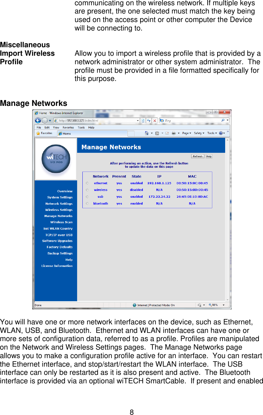
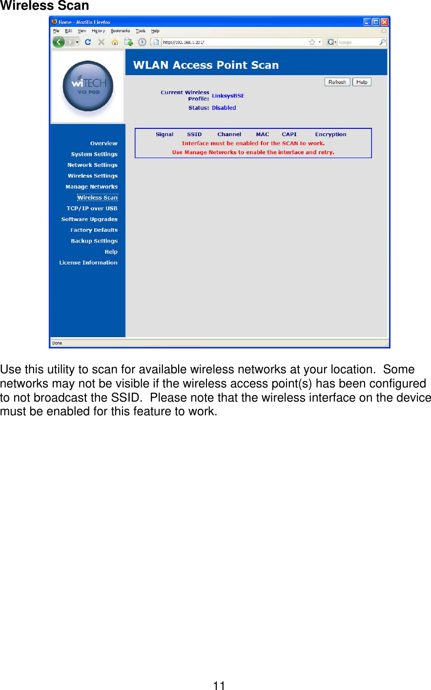
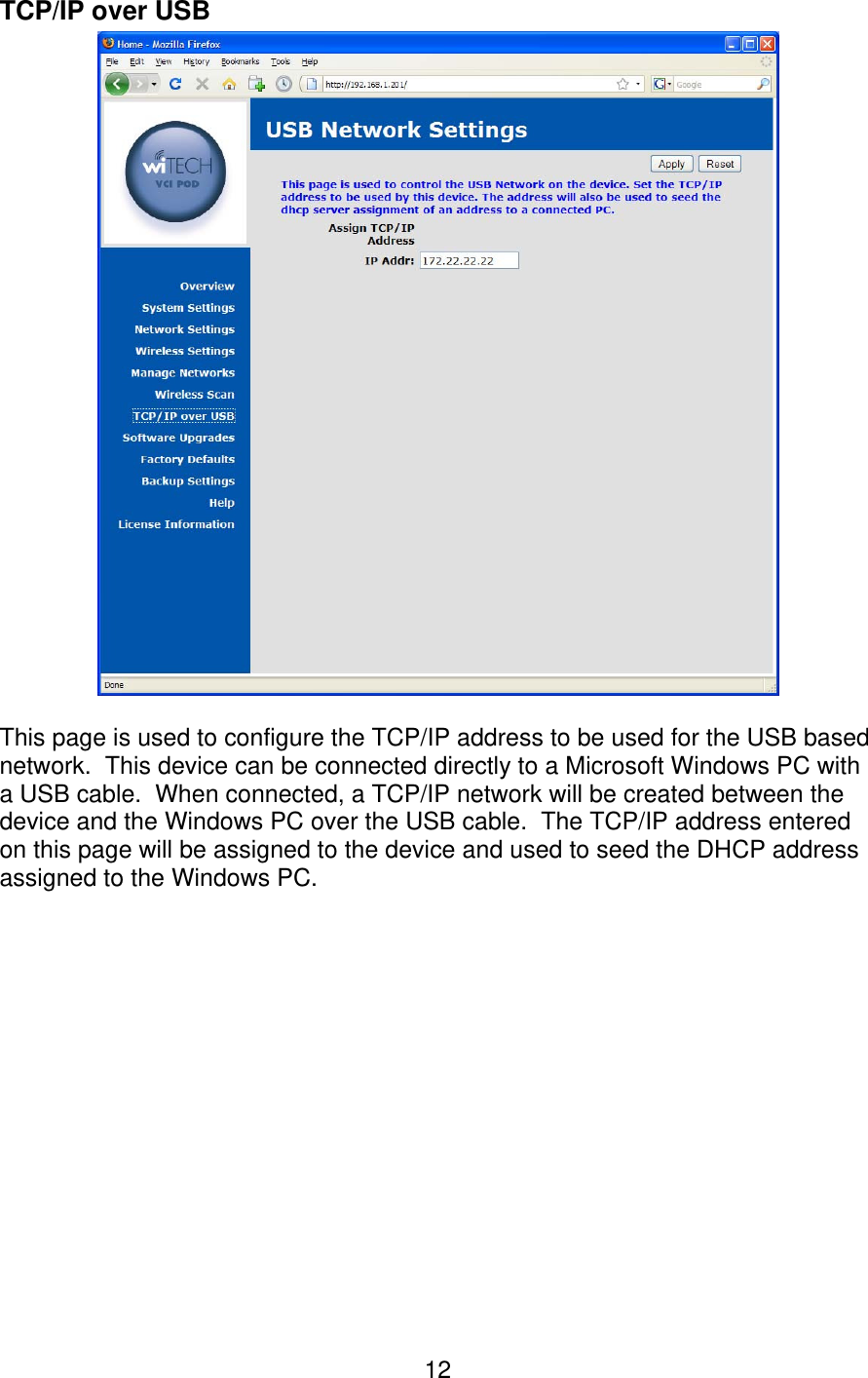
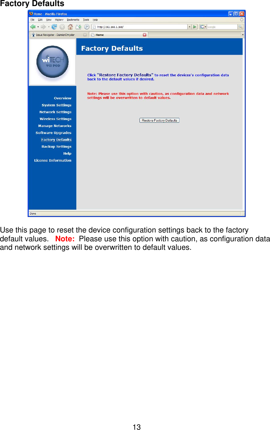
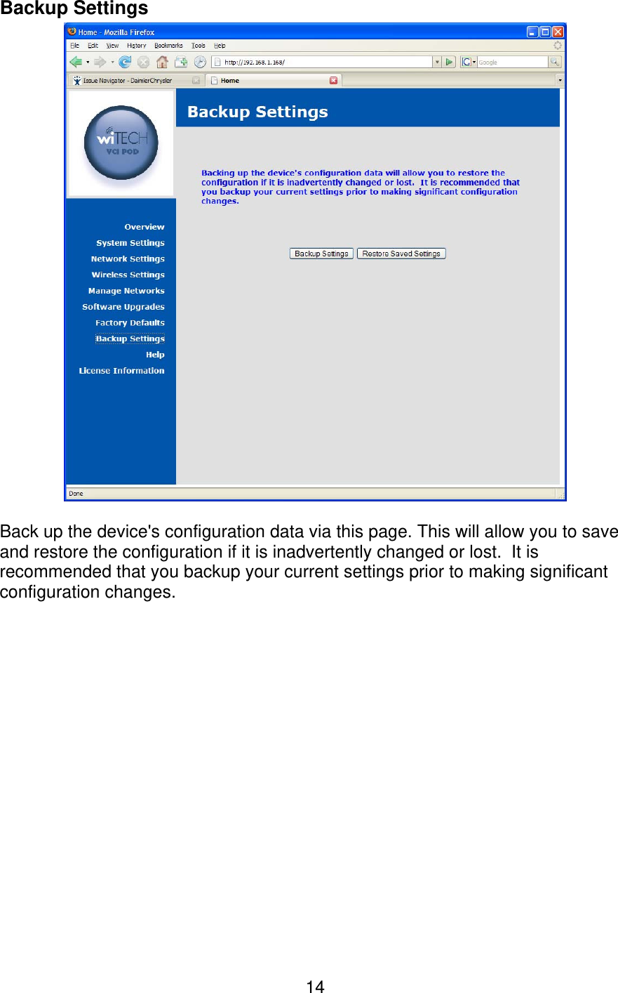
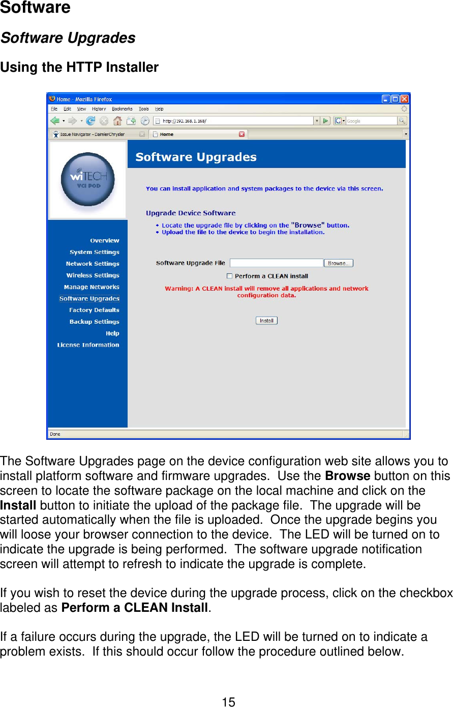
Manual
Manual
Navigation menu
Upload a User Manual
Namespaces
Wiki Guide
HTML
PDF
Info
Views
User Manual
Discussion / Help
Navigation