Bright Star Engineering VCIPOD Automotive Diagnostic Scan Tool User Manual VCIPodUserGuide
Bright Star Engineering, Inc. Automotive Diagnostic Scan Tool VCIPodUserGuide
UserManual.wiki
>
Bright Star Engineering
>
VCIPOD User Manual
>
Users Manual Part 1
Contents
1.
Users Manual Part 1
2.
Users Manual Part 2
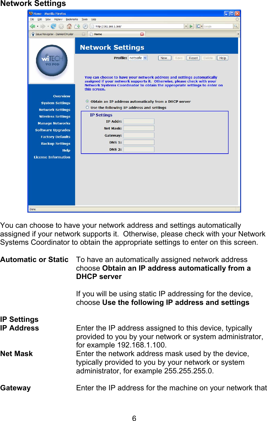
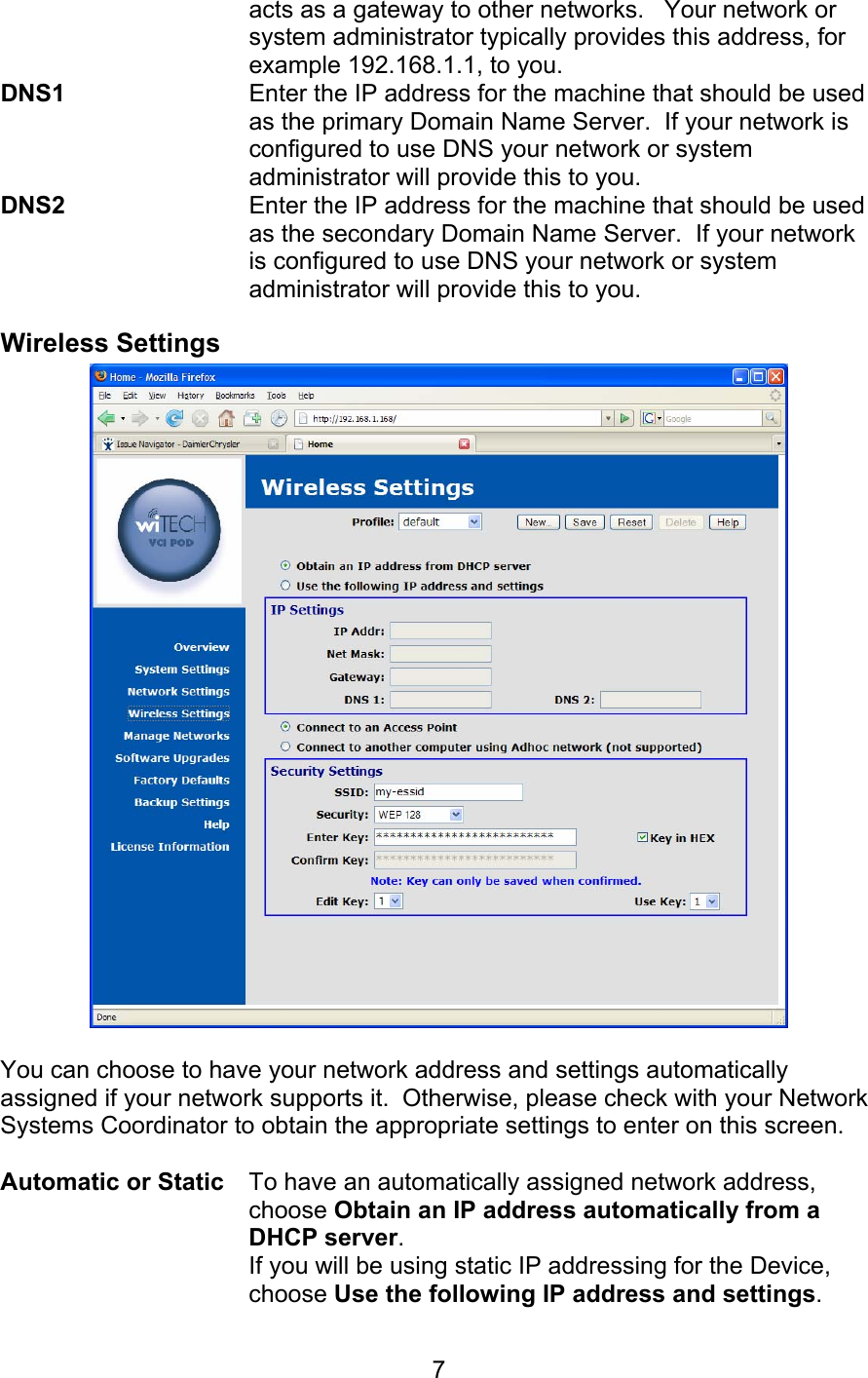
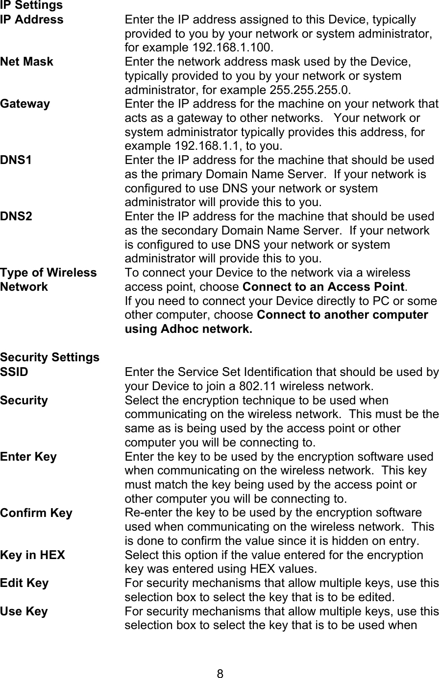
Users Manual Part 1
Navigation menu
Upload a User Manual
Namespaces
Wiki Guide
HTML
PDF
Info
Views
User Manual
Discussion / Help
Navigation