MD755 BRIGHTSIGN Rev2 Rev3
2016-03-31
: Brightsign Md755-Rev3 md755-rev3 website s
Open the PDF directly: View PDF ![]() .
.
Page Count: 7
Rev 062411-4 1
650 N Main Street
Leominster, MA 01453
TOLL FREE 1-877-636-2237
MD-755
Precision Motion Sensor
for BrightSign® Solid
State Digital Sign
Controllers
Overview
The MD755 is a motion sensor
designed to trigger BrightSign
playlist content. Applications include:
¾ Automatic Sign Wake-Up
¾ Trade Show Exhibits
¾ Automated Greetings
¾ Advertisements
¾ Special Announcements and Instructions
¾ Hotel Lobbies
¾ Waiting Rooms
¾ Museums
¾ Facilities Directories
¾ Retail POS
¾ Kiosks
¾ Cinemas
¾ Security Systems
Unlike other motion sensors, the MD-755 plugs directly into a BrightSign interactive sign
controller. It is easy to install, compact, and requires no additional support circuitry,
customization, or separate power sources. The sensor can distinguish movement even in
strong direct sunlit rooms and has an effective range of 6 meters (~ 19 feet).
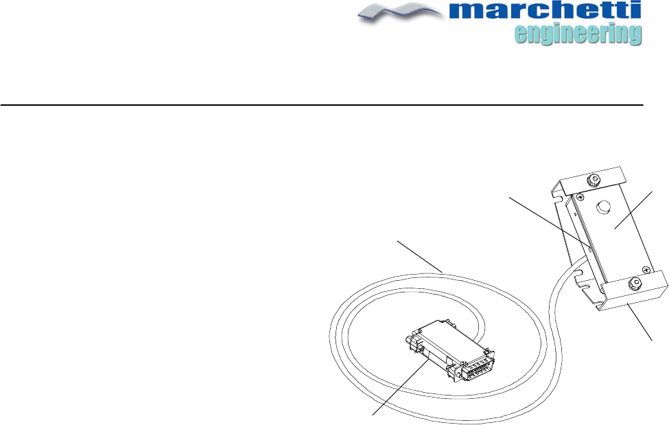
FIGURE 1.1
MD7-55 MOTION SENSOR
ACCESSORY
SENSOR
UNIT
5’ PVC CABLE
DB15 CONNECTOR o
r
PASS-THROUGH
ADAPTOR MALE-FEMALE*
HOLD TIME
ADJUST
UNIVERSAL
MOUNTING
BRACKET
Rev 062411-4 2
The MD-755 is compatible with BrightSign models HD410, 810, 1010, and 1010W via the
BrightSign controller’s DB15 GPIO port. Please refer to the BrightSign User Manual for
more information on how to use this I/O port. Unless specified otherwise, the MD-755 ships
with a standard Male DB15 connector (See Figure 1.9), however, an optional pass-
through adapter is available which allows other GPIO lines to be used. The pass-through
adapter is required if you intend to use a button board or other GPIO functions.
Sensor Detection
There are two versions of the MD-755 ****. The “W” version features a wide detection
zone while the “N” version has a narrow or a “spot” detection zone. The “N” version is
better suited for applications where there is a lot of movement and selective triggering is
required. The “W” version’s wide detection zone is better in areas where more coverage
is desired, for example, when a person enters a large room.
Many BrightSign applications require even greater motion selectivity than what is offered
by the “N” version. Therefore, the area that the sensor “sees” can be reduced by simply
using black electrical tape to create a slit over the sensor’s lens. The smaller aperture
significantly reduces the amount of motion detected. You’ll need to experiment a bit to
find out just how much to cover the lens. Installers can drill a small aperture hole in a
custom-made display panel, behind which, the sensor enclosure is placed.
Sensor Operation and Hold Time
When the MD755 detects motion, it performs the electrical equivalent of pushing a GPIO
INPUT button and plays the corresponding playlist/content ***. Up to three sensors can be
connected to a single BrightSign player’s GPIO port using the optional pass-through
adapter *.
Upon detection, the sensor’s HOLD TIME countdown clock is started, during which time,
the red LED indicator is on. If no further movement is detected, the sensor will re-arm
itself in roughly10 seconds and await the next trigger. Realistically however, viewers will
most likely remain within the sensor’s detection zone. This continued movement adds to
the HOLD TIME clock thereby increasing the length of time that the sensor remains
disarmed. When no further movement is detected AND the HOLD TIME clock expires, the
sensor is rearmed. This feature is necessary for many BrightSign displays, since it allows the
presentation to flow uninterrupted. In other words, whether or not the sensor is rearmed,
your BrightAuthor presentation will continue to play/loop to its media end.
Keep in mind that constant motion within the MD-755’s detection zone, such as that
created at a busy trade show exhibit, will continuously add to the HOLD TIME. If the HOLD
TIME clock keeps adding time, the sensor will never allow itself to be rearmed. Therefore,
strategic placement of the sensor is crucial to you sign/display design. See “Mounting”
for tips on how to limit the detection zone.
Refer to the BrightSign User Guide for more information regarding BrightSign
presentations.
Rev 062411-4 3
Adjusting Hold Time
The following applies only to legacy Denon DNV-755 players using the MD-755, where
HOLD TIME functionality is required. Note that sensor support for Denon models have
been discontinued effective 2/2/10.
If you are using a discontinued MD-755 with a Denon A/V player, HOLD TIME can be set
between approximately 5 and 60 seconds. Use a small flat head screwdriver to adjust
the timer as shown in Figure 1.3. Turning the screw clockwise decreases the hold time.
Stay out of the detection zone when making the adjustment to avoid triggering the
sensor.
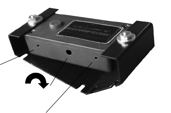
FIGURE 1.3
MD755 INDICATORS AND
SETTINGS
POWER
HOLD
INDICATOR (RED)
HOLD TIME ADJUST
CLOCKWISE = LESS TIME
(DISCONTINUED)
Rev 062411-4 4
Mounting
The MD-755 is intended for indoor use only. A mounting bracket is included, which allows
the sensor to be installed at different angles, providing more control over the detection
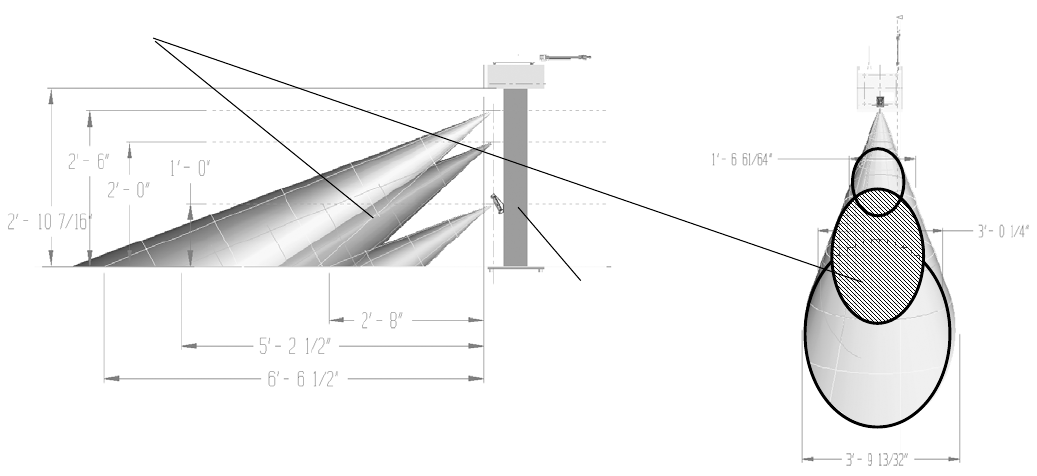
zone. Figure 1.2 shows the MD755 “N” detection characteristics when mounted to a
typical display stand. The standard “N” sensor detects motion +/- 27 degrees top to
bottom, and +/- 20 degrees side-to-side. For example, when the sensor is mounted two
feet from the floor, the detection zone extends roughly five feet in front and
approximately three feet side-to-side, when mounted as shown.
The sensor can also be installed without the supplied bracket. The following section is
particularly useful for installers and integrators.
The MD-755 can be back mounted on a panel having a pre-drilled aperture hole.
Double-sided foam tape and wood screws are used to secure the sensor to a ¾” panel.
For proper detection, a ½” opening in the panel is recommended. A smaller aperture
hole will limit the lens’s ability to “see”, but may be a desired characteristic of your
BrightSign display.
Note: The MD755 will not detect motion if placed behind a transparent surface such as
glass or plexiglass. The sensor’s lens must be exposed to the detection environment.
FIGURE 1.2
“N” VERSION DETECTION
ZONES
RECCOMENDED
ZONE FOR
DISPLAYS
SENSOR
MOUNTED TO
DISPLAY STAND
SIDE VIEW
TOP VIEW
Rev 062411-4 5
Sensor Dimensions
Applications
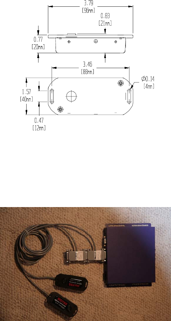
Figure 1.7 shows two MD-755 sensors connected to a single BrightSign interactive player
via the optional pass-through adapters.
The pass-through adapter allows added GPIO functionality such as adding a button
board or other input/output devices that utilize other available GPIO inputs. Since most
BrightSign mtion detection applications do not require the need to use other GPIO’s, the
FIGURE 1.5
MD755 DIMENSIONS
FIGURE 1.7
MULTPLE SENSORS
SENSOR LENS
Rev 062411-4 6
MD-755 ships with a standard DB15 connector making for a more compact installation,
since connecting pass-through adapters end-to-end, as illustrated in Figure 1.7, adds to
the overall depth of the BrightSign hardware installation.
The MD-755 can also be ordered without the plastic enclosure and mounting bracket.
This option is especially useful to BrightSign integrators and installers that have custom
application requirements.
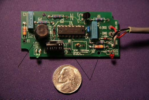
Figure 1.8 shows the circuit board assembly as shipped 1, which includes 5’ cable and
standard DB15 connector. Two 5/8” standoffs are also included (not shown), which can
be used to fasten the circuit board to your custom panel or enclosure. A ½” hole is
recommended to expose the sensor’s lens. Note that the sensor will not operate if the
lens is behind any materials such as glass or plexiglass.
1. POWER LED INDICATOR IS NOT PROVIDED WITH PC BOARD ONLY OPTION. RED TRIGGER LED IS MOUNTED ON BACK OF PC BOARD.
Scripts
Custom BrightSign Scripts are also available that add increased functionality to a display
using the MD-755. For example, it is possible for the MD-755 sensor to trigger multiple
events, play content randomly, disable/enable the BrightSign player’s GPIO ports etc. If
you are interested in a customized BrightSign script, please call us.
FIGURE 1.8
PRINTED CIRCUIT
BOARD ONLY
SENSOR LENS
USE ½” HOLE
MOUNTING HOLES 2 PLACES

Rev 062411-4 7
For more information and volume pricing, please visit www.intelli-sign.com or call:
978-534-0400 x 301
* Specify connector when ordering.
** Specify “W” or “N” when ordering.
*** Unless otherwise requested, GPIO 0 is the default. When ordering, specify the particular GPIO port to
program.
**** Effective 06-01-11 “W” version discontinued
FIGURE 1.9
STANDARD DB15
CONNECTOR
