Broadcast Microwave Services Europe and KG CT2200HDV0000 TV Auxiliary Equipment User Manual CT2200HDV V3 E
Broadcast Microwave Services Europe GmbH & Co. KG TV Auxiliary Equipment CT2200HDV V3 E
User Manual

ENGLISH (UK)
REFERENCE GUIDE
CT2200HDV
Preliminary Pages
Reference Guide: CT2200HDV Page ii
Jul 07
SVENSKA
LÄS DETTA FÖRST!
Om Ni inte förstår informationen i denna handbok
ARBETA DÅ INTE MED DENNA UTRUSTNING.
En översättning till detta språk av denna handbok kan också
anskaffas, på Er bekostnad.
ENGLISH (UK)
Please read this first!
If you do not understand the contents of this manual:
Do not operate this equipment.
Also, translation of this manual into any EC official language can be made
available, at your cost.
DEUTSCH
LESEN SIE ZUERST DIESEN HINWEIS!
Sollte Ihnen der Inhalt dieses Handbuches nicht klar verständlich
sein, dann
Bedienen Sie dieses Gerät nicht.
Eine Übersetzung des Handbuches in dieser Sprache ist gegen
Berechnung lieferbar.
ESPAÑOL
LEA ESTE AVISO PRIMERO!
Si no entiende el contenido de este manual
NO OPERE ESTE EQUIPO.
Podemos asimismo suministrarle una traducción de este manual
al (idioma) previo pago de una cantidad adicional que deberá
abonar usted mismo.
FRANÇAIS
AVANT TOUT, LISEZ CE QUI SUIT!
Si vous ne comprenez pas les instructions contenues dans ce
manuel
NE FAITES PAS FONCTIONNER CET APPAREIL.
En outre, nous pouvons vous proposer, à vos frais, une version
française de ce manuel.
ITALIANO
LEGGERE QUESTO AVVISO PER PRIMO!
Se non si capisce il contenuto del presente manuale
NON UTILIZZARE L’APPARECCHIATURA.
È anche disponibile la versione italiana di questo manuale, ma il costo è a
carico dell’utente.
PORTUGUÊS
LEIA O TEXTO ABAIXO ANTES DE MAIS NADA!
Se não compreende o texto deste manual
NÃO UTILIZE O EQUIPAMENTO.
O utilizador poderá também obter uma tradução do manual para o
português à própria custa.
NEDERLANDS
LEES DIT EERST!
Als u de inhoud van deze handleiding niet begrijpt
STEL DEZE APPARATUUR DAN NIET IN WERKING.
U kunt tevens, op eigen kosten, een vertaling van deze handleiding
krijgen.
DANSK
LÆS DETTE FØRST!
Udstyret må ikke betjenes
MEDMINDRE DE TIL FULDE FORSTÅR INDHOLDET AF
DENNE HÅNDBOG.
Vi kan også for Deres regning levere en dansk oversættelse af
denne håndbog.
SUOMI
LUE ENNEN KÄYTTÖÄ!
Jos et ymmärrä käsikirjan sisältöä
ÄLÄ KÄYTÄ LAITETTA.
Käsikirja voidaan myös suomentaa asiakkaan kustannuksella.

Preliminary Pages
Reference Guide: CT2200HDV Page iii
Jul 07
List of Contents
Chapter 1: Introduction to the CT2200HDV
Gives a general description of the equipment and its main features and
functions. Identifies the controls, indicators and connectors on the front
and rear panels.
Chapter 2: Installing the Equipment
Provides a guide to the suitability of an installation and gives detailed
procedures for the preparation and installation of the equipment. Also
details the external connectors and provides important safety
information.
Chapter 3: Options and Upgrades
This chapter describes the options and upgrades available for the
CT2200HDV models.
Chapter 4: Operating the Equipment Locally
Describes local control in detail. Provides the power-up/power-down
procedures and other general operating/control/set-up procedures.
Annex A: List of Abbreviations
Annex B: Technical Specification
Annex C: Ordering Information

Preliminary Pages
Reference Guide: CT2200HDV Page iv
Jul 07
Contents
Preliminary Pages
List of Contents ........................................................................................ ii
About this Reference Guide ........................................................................vi
Nomenclature...........................................................................................vi
Acknowledgements ..................................................................................vii
General............................................................................................... vii
Registered Trademarks .........................................................................vii
Trademarks .........................................................................................vii
Warnings, Cautions and Notes .................................................................. viii
Heed Warnings ................................................................................... viii
Read Instructions ................................................................................ viii
Follow Instructions .............................................................................. viii
Retain Instructions .............................................................................. viii
EMC Compliance ..................................................................................... viii
Contact Information ..................................................................................ix
BMS-Europe Customer Services...............................................................ix
Technical Training ................................................................................. x
Customer Services and Technical Training Postal Address............................ x
Return of Equipment.............................................................................. x
Technical Publications ............................................................................ x
Chapters 1 to 4
Introduction to the CT2200HDV .................................................................. 1
Preliminary Remarks.............................................................................. 1
Designation and P/N .............................................................................. 1
Description ........................................................................................... 2
Installing the Equipment ............................................................................ 4
Safety instructions................................................................................. 4
Connectors ........................................................................................... 5
Shut-Down ........................................................................................... 6
Operating the Equipment ........................................................................... 7
Multifunctional display............................................................................ 7
Frequency input .................................................................................... 8
Software version ................................................................................... 8
Automatically display cutoff .................................................................... 9
Display contrast .................................................................................... 9

Preliminary Pages
Reference Guide: CT2200HDV Page v
Jul 07
Appendix A List of Abbreviations
Appendix B Technical Specification
B.1… Compliance .................................................................................. B-1
B.1.1 Safety ................................................................................... B-1
B.1.2 EMC ...................................................................................... B-1
B.1.3 Shock and Vibration ................................................................ B-2
B.1.4 CE Marking ............................................................................. B-2
B.1.5 FCC Marking............................................................................ B-2
B.1.6 TV Pick-Up Channel Assignments for US and Canadian Users.......... B-2
B.2 Technical Specifications................................................................... B-3
Appendix C Ordering Information
List of Figures
Chapters 1 to 4,
Page
Figure 1
Block Diagram of the CT2200HDV ............................................... 2
Figure 2
Input connector of the CT2200HDV.............................................. 5

Preliminary Pages
Reference Guide: CT2200HDV Page vi
Jul 07
About this Reference Guide
This Reference Guide provides instructions and information for the
installation and operation of the CT2200HDV.
This Reference Guide should be kept in a safe place for reference for the
life of the equipment. It is not intended that this Reference Guide will be
amended by the issue of individual pages. Any revision will be by a
complete reissue. Further copies of this Reference Guide can be ordered
from the address shown on page ix. If passing the equipment to a third
party, also pass the relevant documentation.
Issues of this Reference Guide are listed below:
Issue Date Build Version Comments
1 May 2007 1.0 Initial release.
2 Jul 2007 2.0 Update Information for use in US and Canada
Note…
The Build Version in the table refers to an overall number which
encompasses all the various software/firmware versions of video,
audio, etc in the device.

Preliminary Pages
Reference Guide: CT2200HDV Page vii
Jul 07
Acknowledgements
General
All best endeavours have been made to acknowledge registered
trademarks and trademarks used throughout this Reference Guide. Any
notified omissions will be rectified in the next issue of this Reference
Guide. Some trademarks may be registered in some countries but not in
others.
Registered trademarks and trademarks used are acknowledged below and
marked with their respective symbols. However, they are not marked
within the text of this Reference Guide.
Registered Trademarks
AC-3
®
, Dolby Digital
®
and Pro Logic
®
are registered trademarks of Dolby
Laboratories Licensing Corporation.
Musicam
®
is a registered trademark of Thomson and Télédiffusion de
France (TDF), Europe, and is a registered trademark of CCS (now Musicam
USA Incorporated), USA.
Ethernet
®
is a registered trademark of Xerox Corporation.
XILINX
®
is a registered trademark of Xilinx Inc.

Preliminary Pages
Reference Guide: CT2200HDV Page viii
Jul 07
Warnings, Cautions and Notes
Heed Warnings
All warnings on the product and in the operating instructions should be
adhered to. The manufacturer can not be held responsible for injuries or
damage where warnings and cautions have been ignored or taken lightly.
Read Instructions
All the safety and operating instructions should be read before this product
is operated.
Follow Instructions
All operating and use instructions should be followed.
Retain Instructions
The safety and operating instructions should be retained for future
reference.
Warnings…
Warnings give information which, if strictly observed, will
prevent personal injury or death, OR DAMAGE TO PERSONAL
PROPERTY OR THE ENVIRONMENT. They are boxed and
shaded for emphasis, as in this example, and are placed
immediately preceding the point at which the reader
requires THEM.
Cautions...
Cautions give information which, if strictly followed, will prevent
damage to equipment or other goods. They are boxed for emphasis,
as in this example, and are placed immediately preceding the point
at which the reader requires them.
Notes...
Notes provide supplementary information. They are highlighted for
emphasis, as in this example, and are placed immediately after
the relevant text.
EMC Compliance
This equipment is certified to the EMC requirements detailed in Annex B,
Technical Specification. To maintain this certification, only use the leads
supplied or if in doubt contact Customer Services.

Preliminary Pages
Reference Guide: CT2200HDV Page ix
Jul 07
RF Exposure Info:
For body worn operation, device has been tested and meets FCC RF
exposure guidelines when used with an accessory that contains no metal
and that positions device a minimum of 25 mm from the body. Use of
other accessories may not ensure compliance with FCC RF exposure
guidelines.
Technical Training
Training Courses
BMS Europe provides a wide range of training courses on the operation
and maintenance of our products and on their supporting technologies.
BMS can provide both regularly scheduled courses and training tailored to
individual needs. Courses can be run either at your premises or at one of
our dedicated training facilities.
Where to Find Us
For further information on BMS Europe training program please
contact us:
International Telephone: + 49 6124 7239-00
International Facsimile + 49 6124 7239-29
Customer Services and BMS Europe Postal Address
BMS-Europe GmbH & Co. KG
Schwalbacher Straße 12
65321 Heidenrod – Kemel
Germany
Return of Equipment
If you need to return equipment for repair, please contact
Tel: + 49 6124 7239-00
Fax: + 49 6124 7239-29
BMS-Europe GmbH & Co. KG
Schwalbacher Straße 12
65321 Heidenrod – Kemel
Germany

Chapter 1: Introduction
Reference Guide: CT2200HDV Page 1
May 07
Introduction to the CT2200HDV
Preliminary Remarks
The present manual is provided for users and operators of the CT2200HDV
Transmitter. It is intended to support the installation, operation, maintenance and
daily use of the unit in general.
The manual should be kept with the CT2200HDV Transmitter and may be consulted
when questions occur. If problems should remain after you have read the manual
carefully or if you have any further questions concerning the functionality or operation
of the Transmitter, please contact the Customer Service.
Designation and P/N
Designation CT2200HDV
Frequency range P/N
2.0 – 2.3 GHz 11.2403.100 Sony V-mount
2.0 – 2.3 GHz 11.2403.300 Anton Bauer
2.3 – 2.7 GHz 11.2403.000 Sony V-mount
2.3 – 2.7 GHz 11.2403.200 Anton Bauer
Chapter 1: Introduction
Reference Guide: CT2200HDV Page 2
May 07
Description
General Information on D-ENG (Digital Electronic News Gathering)
The introduction of the DVB standard established the basis for digital broadcast video
transmission making efficient use of the available bandwidth. Powerful compression
algorithms allow a reduction in the amount of data to be transferred, while
maintaining the high quality standards for video and audio signals used in broad-
casting applications. New modulation techniques and error correction algorithms
ensure a secure signal transmission even when the transmission conditions are poor.
The DVB-T standard was established for terrestrial digital TV broadcasting, in
particular considering the difficult conditions of radio transmission. The highly efficient
OFDM multicarrier modulation procedure enables transmission without interference
even under multipath propagation conditions occurring with nondirectional
transmission or reception. Practical experience soon has proved that the DVB-T
standard guarantees ruggedness of transmission to an extent even allowing mobile
reception.
Increasing miniaturization, in particular of MPEG encoders and OFDM modulators,
enables using the DVB-T standard for mobile portable transmission systems.
Previous analog FM systems were adversely affected by signal reflections directly
resulting in video and audio interferences. Such effects do not occur when the digital
ENG system (D-ENG) is deployed. Even mobile transmission from moving vehicles or
the use of omnidirectional antennas on the transmitting or receiving side does not
impair the picture or sound quality at all, opening a completely new range of
applications in TV production and news gathering.
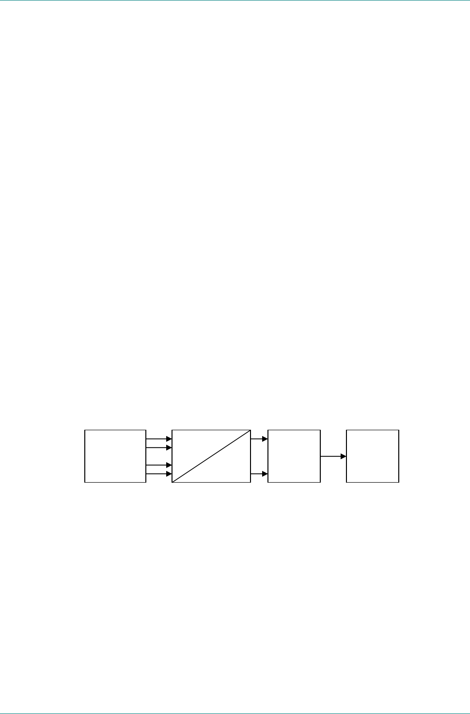
Functional Overview
Figure 1 Block Diagram of the CT2200HDV
The CT2200HDV essentially contains the following functional blocks:
• MPEG-2 COFDM Modulator
• D/A Converter
• IQ-Modulator
• Linear Low-Power Amplifier.
IEEE1394a
(Firewire)
COFDM
Modulator
D
A
I
Q
IQ
Linear -
Power
Amplifier
Output

Chapter 1: Introduction
Reference Guide: CT2200HDV Page 3
May 07
Video Inputs
The CT2200HDV accepts only HDV encoded information at the input:
• HDV IEEE-1394a (Firewire)
CT2200HDV operates with all currently available HDV cameras.
OFDM Modulator
The digital data signal for wireless transmission is processed by the OFDM Modulator
and following IQ MOdulator. The OFDM (Orthogonal Frequency Division Multiplex)
modulation procedure has a major impact on the transmission properties and was
specifically developed for terrestrial radio transmission.
The setup of the OFDM modulator occurs automatically dependent on HDV format of
the camera.
Each setting is well proven and provides best quality for the customer without any
need of OFDM Modulator setup.
User interface
With its integrated Multifunctional Display it is easy to set up the transmit frequency,
display contrast and automatic display cutoff. The current Software version can also
be displayed.
Low-Power Linear Amplifier
The linear power amplifier amplifies the output signal of the Modulator to an output of
about 400 mW (+26 dBm). The output port of the Low-Power Amplifier is located on
top of the CT2200HDV.

Chapter 3: Options and Upgrades
Reference Guide: CT2200HDV Page 4
May 07
Installing the Equipment
Safety instructions
Warning
The regulations of VDE0100 must be observed for
installation and operation of the unit.
Caution
• Establish all other connections before starting the unit by
connecting it to 12VDC. Essential a valid video signal must be
connected to the desired input before power on the CT2200HDV.
• When you connect the CT2200HDV as described in the following
sections, make sure that the "Caution" instructions given there
are observed.
• Make sure that there is sufficient air circulation to ensure
adequate cooling of the unit.
External forced ventilation may be required if the unit is installed
in a rack or cabinet.

Chapter 3: Options and Upgrades
Reference Guide: CT2200HDV Page 5
May 07
Connectors
Figure 2 Input connector of the CT2200HDV
• RF Connector
The RF output signal of the Low-Power Amplifier is fed out at the SMA(f)
connector on top of the unit.
The CT2200HDV provides a RF output of about 400mW (+26dBm).
The signal may be further amplified by a secondary amplifier optimized for
HD-COFDM signals.
See section "Connecting the RF Output", page 6

Chapter 3: Options and Upgrades
Reference Guide: CT2200HDV Page 6
May 07
Connecting Signal Sources
The encoded Video/Audiosignal supplied by the camera have to applied to the IEEE
1394a connector of the transmitter.
Connecting the RF Output
A Omni directional antenna with SMA(m) connector can be directly mount at the RF
out socket.
Connecting the 12VDC Supply Voltage
Caution
When using a battery or power pack, make sure that the maximum
supply current is at least 3A and the output voltage matches the
input voltage range of the CT2200HDV.
Failure to comply with these requirements may cause fatal
damage to the battery/power pack and/or CT2200HDV.
Battery Powered Operation of the CT2200HDV
Many types of batteries are available on the market and we tried to support the best
ones.
On this way it is possible to order the Transmitter with Anton Bauer or Sony V-Mount.
Others on request.
Shut-Down
Caution
To shut-down the unit, first disconnect it from the 12VDC supply
voltage.
After disconnection from the supply voltage by removing the battery or disconnecting
the 12VDC supply cable, the other connecting cables can be removed from the unit.

Chapter 4: Operating the Equipment
Reference Guide: CT2200HDV Page 7
May 07
Operating the Equipment
Multifunctional display
During power up time the display of the CT2200HDV pass a self test. It displays
manufacture, transmitter type and software version.
After the selftest, the current frequency is displayed.
With its automatically COFDM setup the customer menu is very easy to handle. Due to
press and hold the button 3 for approximately 2sec. the setup menu is accessibly.
Menu structure:
Frequency input
Software version
Automatical display cutoff
Display contrast
To get access to any submenu press button 1 or 2
BMS
HDV
SW v 0.88
2350.0MHz
Initialization
Button 1 Button 2 Button 3

Chapter 4: Operating the Equipment
Reference Guide: CT2200HDV Page 8
May 07
Frequency input
In the Submenu „Frequency“ the current frequency is displayed.
To change the frequency press button 3 for approximately 2 sec.
The flashing curser indicates the current changing position of the frequency. With
button 1 or 2 the marked digit can be increased or decreased about one digit. To
change the next lower digit, press button 3 and repeat the step before. When
frequency change is complete so save the changes by press button 3 again to quit the
frequency setup.
NOTE: For use in US see guidance in chapter B.1.6
Software version
To display the actual software version enter the submenu „Software“.
** setup: **
Frequency
2350.0
** setup: **
Frequency
2
3
50.0
** setup: **
Software
0.88

Chapter 4: Operating the Equipment
Reference Guide: CT2200HDV Page 9
May 07
Automatical display cutoff
The display can be set to turn off automatically after a preset time of inactivity.
Select "Disp off" submenu and press button 3 for 2 seconds. Use buttons 1 and 2 to
set value. Set the desired time-out interval between 015 to 240 seconds. A value of
000 (default) causes the display to stay on continuously.
To exit this submenu, press button 3.
Display contrast
The display contrast can be adjusted from 0 (dark) to 127 (light). The default value is
031.
Select "Contrast" submenu and press button 3 for 2 seconds. Use buttons 1 and 2 to
set value.
To exit this submenu, press button 3.
** setup: **
Disp off
000s
** setup: **
Contrast
031

Annex A: List of Abbreviations
Reference Guide: CT2200HDV Page A-1
May 07
List of Abbreviations
The following specific abbreviations are used within this document:
4:2:0 Digital video coding method in which the color difference
signals are sampled on alternate lines at half the luminance
rate.
4:2:2 Digital video coding method in which the color difference
signals are sampled on all lines at half the luminance rate.
COFDM Coded Orthogonal Frequency Division Multiplex
(digital modulation procedure)
Composite CVBS video signal, 1 V
pk-pk
CVBS Color Video Black Sync Signal
D-ENG Digital Electronic News Gathering
DVB-T Digital Video Broadcasting Terrestrial
EMC Electromagnetic Compatibility
ETS European Telecommunications Standard
FBAS German for CVBS
FEC Forward Error Correction
FM Frequency Modulation (analog modulation procedure)
IF Intermediate Frequency
IEC International Electrotechnical Committee
ISO International Standards Organisation
kbit/s 1000 bits per second
Mbit/s Million bits per second.
MP@ML Main Profile at Main Level: A subset of the MPEG-2 standard,
which supports digital video storage (DVD etc.) and
transmissions up to 15 Mbit/s over various mediums.
MPEG Motion Pictures Experts Group (compression technique)
NTSC National Television Systems Committee
OFDM Orthogonal Frequency Division Multiplex
QAM Quadrature Amplitude Modulation: A method of modulating
digital signals
QPSK Quadrature phase shift keying (digital modulation technique)
PAL Phase Alternation Line (a color TV broadcasting system)
PCM Pulse Code Modulation
RF Radio Frequency
RGB Red, green, blue. The chroma information in a video signal.

Annex A: List of Abbreviations
Reference Guide: CT2200HDV Page A-2
May 07
RS 232, RS-232 EIA-232
SDI Serial Digital Interface
TS Transport Stream
XLR Audio connector featuring three leads, two for signal and one
for GND
YUV Y: Luminance component (brightness),
U and V: chrominance (color difference)
Y/C Broadcast Video with separate color, Y luminance and C
chroma (sometimes called S-Video)

Annex B: Technical Specification
Reference Guide: CT2200HDV Page B-1
May 07
Technical Specification
B.1 Compliance
1
B.1.1 Safety
This equipment has been designed and tested to meet the requirements of
the following:
EN 60950 European Safety of information technology equipment
including business equipment.
IEC 60950 International Safety of information technology equipment
including business equipment.
B.1.2 EMC
2
The equipment has been designed and tested to meet the following:
EN 55022
and
AS/NZS 3548
European
Australia and
New Zealand
Emission Standard
Limits and methods of measurement of
radio frequency interference
characteristics of information
technology equipment - Class A.
EN 61000-3-2
3
European Electromagnetic Compatibility (EMC),
Part 3 Limits; Section 2. Limits for
harmonic current emissions (equipment
input current ≤ 16 A per phase).
EN 61000-3-3
3
European Electromagnetic Compatibility (EMC),
Part 3. Limits; Section 3. Limitation of
voltage fluctuations and flicker in low
voltage supply systems for equipment
with rated current ≤ 16 A.
EN 55024:1998 European Information technology equipment -
Immunity characteristics - Limits and
methods of measurement.
1
The version of the standards shown is that applicable at the time of manufacture.
2
The EMC tests were performed with the Technical Earth attached, and configured using recommended cables.
3
Applies only to models of the equipment using mains (ac) power sources.

Annex B: Technical Specification
Reference Guide: CT2200HDV Page B-2
May 07
B.1.3 Shock and Vibration
The device chassis complies with the requirements of ETS 300-019-2-5
Table 2, for both non-operational and operational states, without any
special mounting or casing requirements over and above the standard
mounting requirements specified.
ETS 300-019-2-5 European Equipment Engineering (EE):
Environmental conditions and
environmental tests for
telecommunications equipment
Part 2-5: Specification of environmental
tests Ground Vehicle Installations.
Table 2.
B.1.4 CE Marking
The CE mark is affixed to indicate compliance with the following
directives:
89/336/EEC of 3 May 1989 on the approximation of the laws of the
Member States relating to electromagnetic compatibility.
73/23/EEC of 19 February 1973 on the harmonisation of the laws of the
Member States relating to electrical equipment designed for use within
certain voltage limits.
Note...
The CE mark was first affixed to this product in 2006.
B.1.5 FCC Marking
FCC ID: VFB-CT2200HDV0000
This device complies with Part 74 of the FCC Rules. Operation is subject to the following two
conditions. (1) this device may not cause harmful interference, and (2) this device must accept any
interference received, including interference that may cause undesired operation.
B.1.6 TV Pick-Up Channel Assignments for US and Canadian
Users
The preferred channel arrangement defined for the TV pick-up systems are up to
seven 12 MHz one-way RF channels in the 2025 to 2110 MHz band.

Annex B: Technical Specification
Reference Guide: CT2200HDV Page B-3
May 07
In the major metropolitan preference will be given to TV pick-ups.
Elsewhere, the level of priority access given to TV pick-ups will be at the discretion of
the regional offices.
To the extent possible, TV pick-up usage should avoid the spectrum designated for
very low capacity systems.
Arrangement:
Band G(n) = 2019.5 + 12n
Where: n = 1 to 7, and G(n) is the centre frequency of the channel in MHz.
G1: 2031.50
G2: 2043.50
G3: 2055.50
G4: 2067.50
G5: 2079.50
G6: 2091.50
G7: 2103.50
Due to the large area affected by helicopter usage of TV Pick-ups, some restrictions
on the number of TV Pick-up channels available for this application may be applied by
the regional offices. These restrictions may be based on consideration of factors such
as frequency assignment re-use, availability of assignments in other TV Pick-up bands
and co-existence with point-to-point systems.
Note: The TV Pick-up channel plan is harmonized with Canada and
USA, and may be changed in accordance with the future changes
and availability of equipment.

Annex B: Technical Specification
Reference Guide: CT2200HDV Page B-4
May 07
B.2 Technical Specifications
Signal Parameters
Output (RF) 2.3 – 2.7 GHz (standard; others on request)
Connector: SMA female, 50 Ω
26 dBm (400mW)
Audio/Video Inputs IEEE 1394a (Firewire)
Modulator COFDM, ETS 300744, 2k carriers only
Bandwidth: 8 MHz
64 QAM
automatic mode for guard interval and FEC
Power Input 10.2 – 17.5 VDC
(Battery powered)
Power Consumption 13W
Operating Conditions Ambient temperature
-20°C – 45°C
Dimensions (W x D x H) 138 mm x 87 mm x 27 mm (without Battery bracket)
Weight 0.33 kg approx
Connectors
Input Voltage 10.2 – 17.5V DC
via Battery bracket
1 GND
2 +12V
Data Input 4-pin Lemo, female series EGG.0B.304.CLL
1 TPA- Transmit strobe / Receive data
2 TPA+ Transmit strobe / Receive data
3 TPB- Receive strobe / Transmit data
4 TPB+ Receive strobe / Transmit data
Shielding : GND

Annex B: Technical Specification
Reference Guide: CT2200HDV Page B-5
May 07
Antenna Output SMA, female; 50 Ω
Centre Signal
Shielding GND

Annex C: Ordering Information
Reference Guide: CT2200HDV Page C-1
May 07
Ordering Information CT2200HDV Models
P/N COFDM
Bandwith Frequency Range * Battery bracket
11.2403.000 8 MHz 2.3 – 2.7 GHz Sony V-mount
11.2403.100 8 MHz 2.0 – 2.3 GHz Sony V-mount
11.2403.200 8 MHz 2.3 – 2.7 GHz Anton Bauer
11.2403.300 8 MHz 2.0 – 2.3 GHz Anton Bauer
*
Other frequency ranges on request
Manufacturer: BMS-Europe GmbH & Co. KG