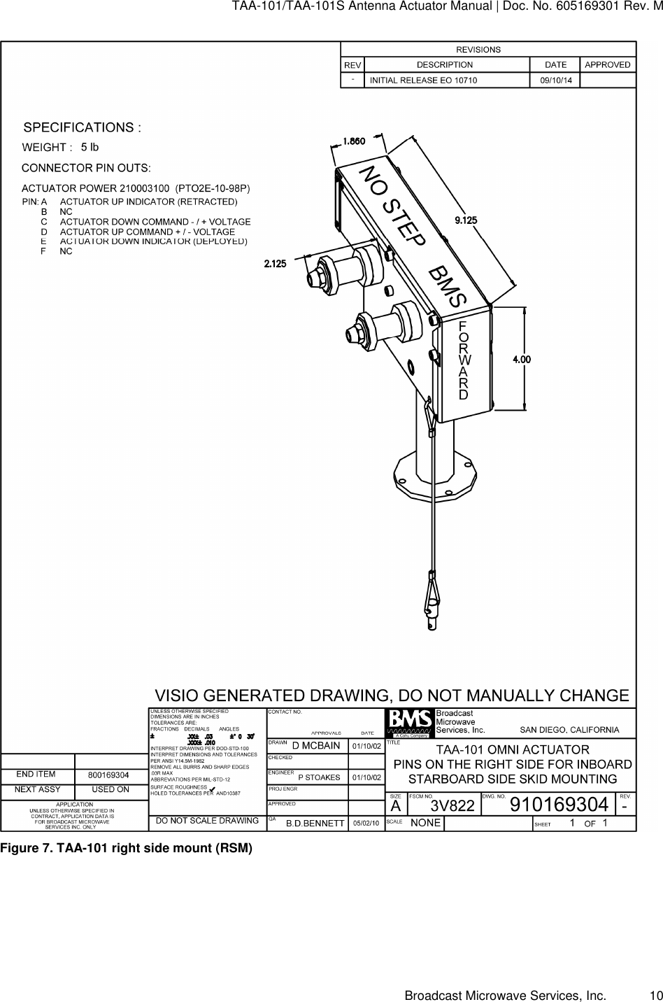
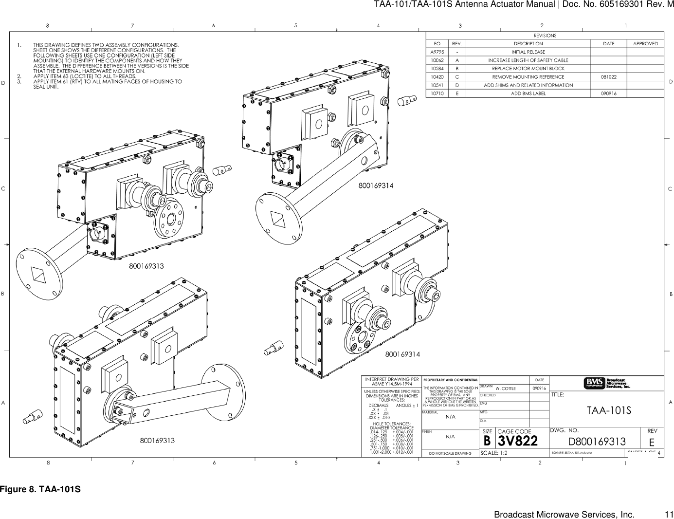
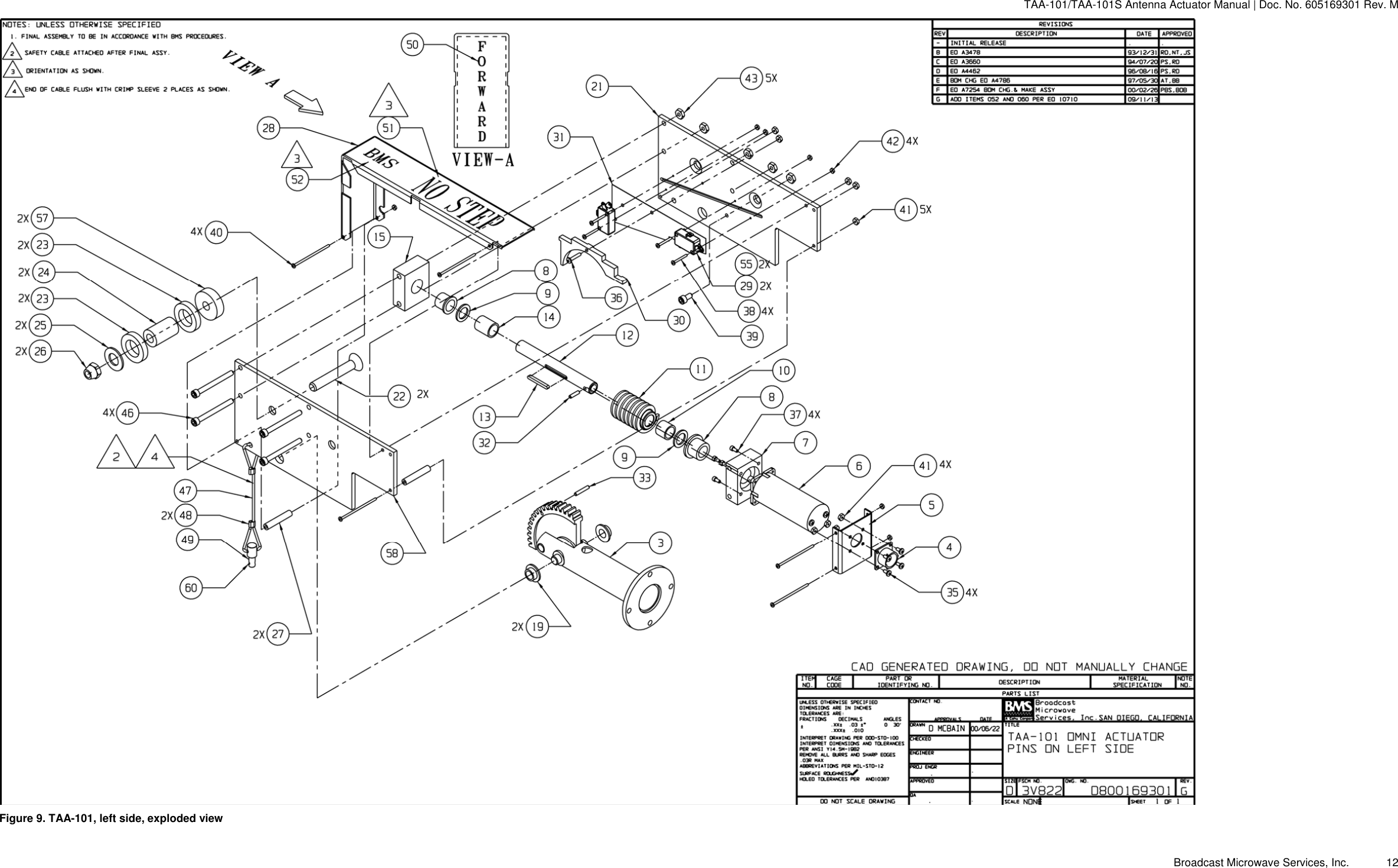
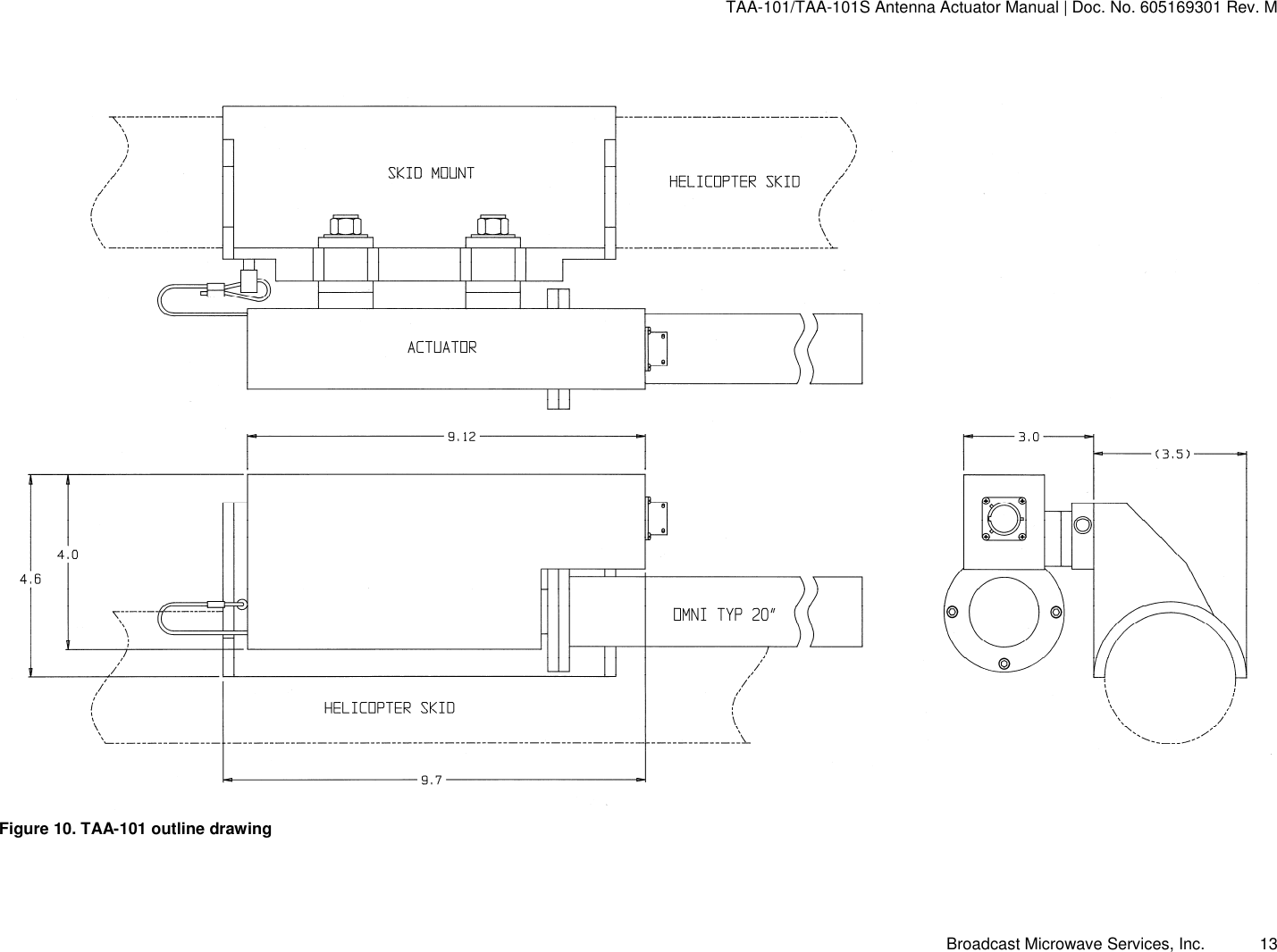
Broadcast Microwave Services Europe and KG CT6540ARI6466 TV Auxiliary Equipment User Manual 605169301N TAA 101 sm
Broadcast Microwave Services Europe GmbH & Co. KG TV Auxiliary Equipment 605169301N TAA 101 sm
Contents
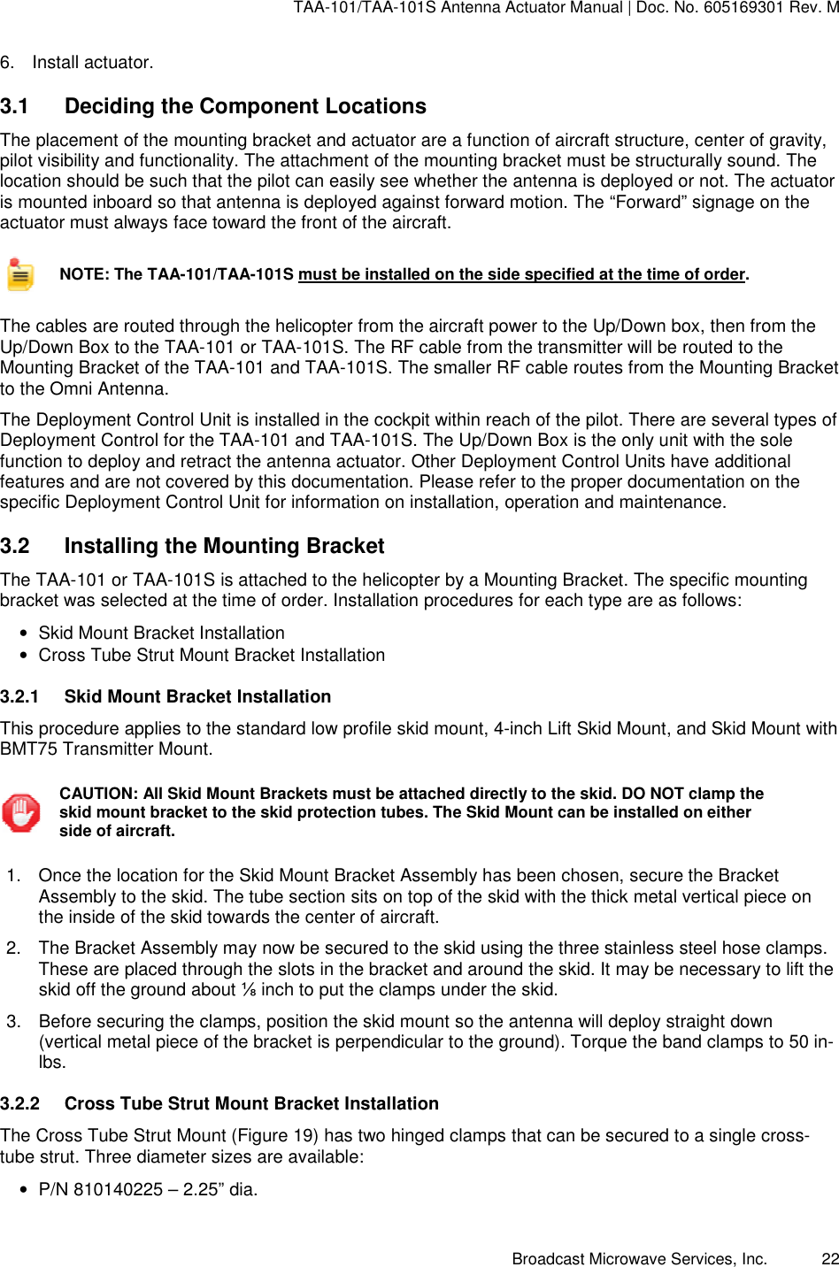
- 1. Installation Instructions
- 2. User Manual
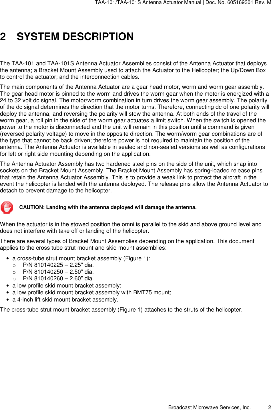
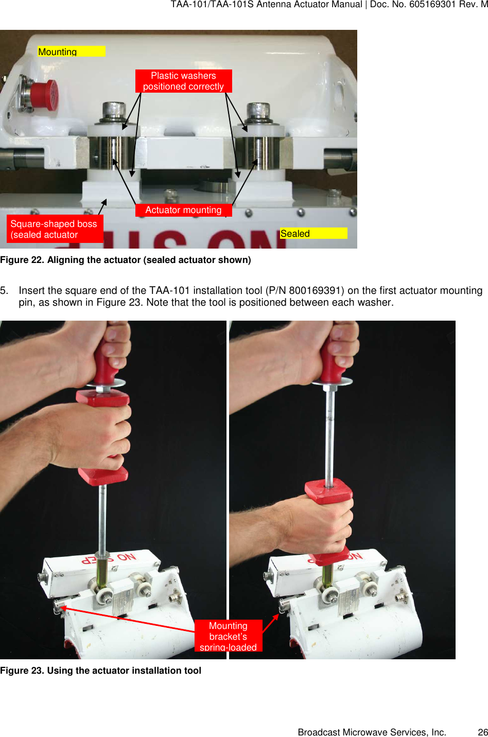
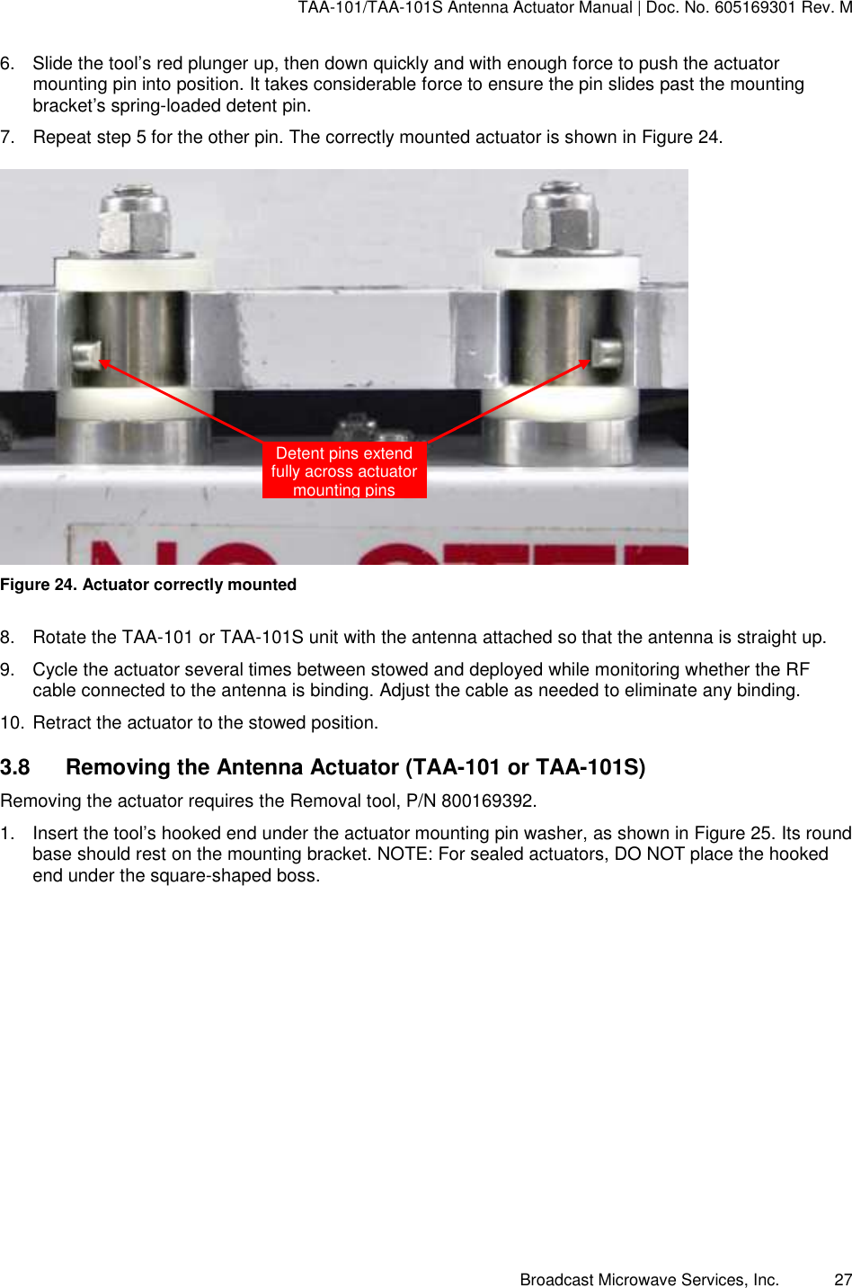
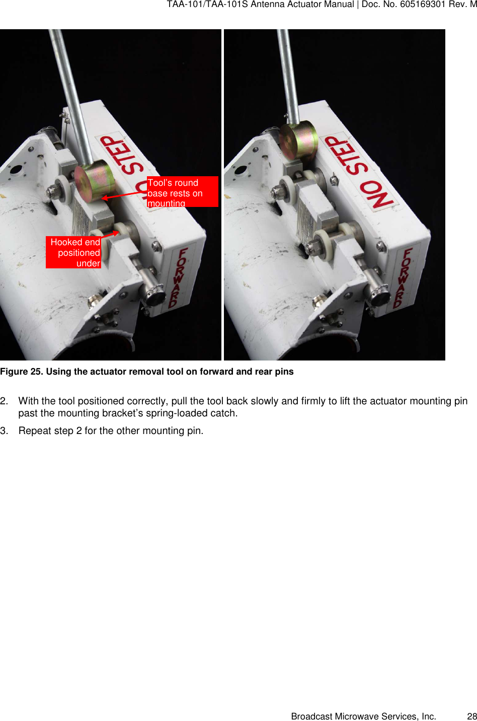
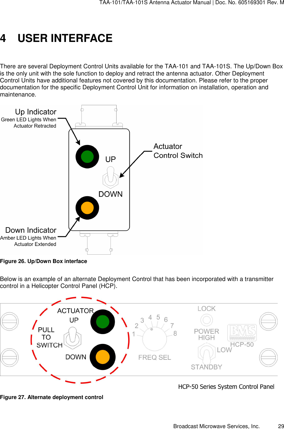
Installation Instructions