Broadcast Microwave Services Europe and KG CT6540ARI6466 TV Auxiliary Equipment User Manual
Broadcast Microwave Services Europe GmbH & Co. KG TV Auxiliary Equipment
Contents
- 1. Installation Instructions
- 2. User Manual
User Manual

BROADCAST MICROWAVE SERVICES
CT6540ARINC
Reference Guide v. 1.2
The picture is just for illustration and may differ from components supplied

This document and the information contained in it is the property of Broadcast
Microwave Services Inc. and may be the subject of patents pending and granted.
It must not be used for commercial purposes nor copied, disclosed, reproduced,
stored in a retrieval system or transmitted in any form or by any means
(electronic, mechanical, photocopying, recording or otherwise), whether in whole
or in part, without prior written agreement issued by BMS.
Copyright © 2009 Broadcast Microwave Services, Inc. All rights reserved.
Broadcast Microwave Services Europe GmbH
Schwalbacherstraße 12
65321 Heidenrod, Germany
Tel: +49 (6124) 7239 00
Fax: +49 (6124) 7239 29
E-Mail: saleseurope@bms-inc.com
Internet: www.bms-inc.com
Broadcast Microwave Services, Inc.
12367 Crosthwaite Circle, Dock 10
Poway, CA 92064
Tel: +1 (858) 391-3050 • Toll-free (US): 800-669-9667
Fax: +1 (858) 391-3049
Email: support@bms-inc.com
Internet: www.bms-inc.com

A
Contents
Contents
1 About This Reference Guide ................................................................. 1
1.1 Read this first ............................................................................. 1
1.2 Versions of this Reference Guide ............................................... 3
1.3 Designation and P/N .................................................................. 3
2 Safety Warnings ..................................................................................... 4
2.1 Registered and General Trademarks ......................................... 4
2.2 EMC Compliance ....................................................................... 5
2.3 Compliance ................................................................................ 5
2.4 C-Tick Marking ........................................................................... 5
2.5 CE Marking ................................................................................. 5
2.6 FCC Marking .............................................................................. 5
2.7 RTCA/DO-160 ............................................................................ 5
3 Installing the Transmitter ...................................................................... 6
3.1 ARINC Mounting Plate ............................................................... 7
3.2 Mounting Instructions ................................................................. 8
4 Dismounting the Transmitter .............................................................. 11
5 Controlling the System ........................................................................ 12
6 Technical Specifications ..................................................................... 16
6.1 CE Marking ............................................................................... 16
6.2 FCC Marking ............................................................................ 16
6.3 C-Tick Marking ......................................................................... 17
6.4 Safety ....................................................................................... 17
6.5 Signal Parameters .................................................................... 18
6.6 Connectors Transmitter ............................................................ 19
6.7 Connectors Control Panel ........................................................ 21
6.8 Cabling and Connectors Overview ........................................... 22
6.9 Cable DC for ARINC Control Panel .......................................... 23
6.10 Cable CT6540ARINC (CONTROL) to ARINC Control Panel ... 23
6.11 Cable Actuator to ARINC Control Panel ................................... 24
6.12 Programming Cable for ARINC Control Panel ......................... 24

B
Contents
7 Warranty ................................................................................................ 25
8 Glossary ................................................................................................ 27
9 Index ...................................................................................................... 31
10 Contact Information ............................................................................. 33
10.1 Customer Support .................................................................... 33
10.2 Training Courses ...................................................................... 33
10.3 Claims ...................................................................................... 33

C
List of Figures
List of Figures
Figure 1: Ventilation Openings ........................................................................... 7
Figure 2: Mounting Plate Overview .................................................................... 7
Figure 3: Retainer Locations ............................................................................... 8
Figure 4: Fixing the Transmitter ......................................................................... 8
Figure 5: Locking the Transmitter ...................................................................... 8
Figure 6: Mounted Transmitter ........................................................................... 9
Figure 7: CT6540ARINC Connector Panel ......................................................... 9
Figure 8: Control panel connectors (with actuator control)......................... 10
Figure 9: Control panel connector (without actuator control) ....................... 10
Figure 10: Control panel with actuator switch ................................................ 12
Figure 11: Control panel without actuator switch ........................................... 12
Figure 12: Cabling and Connectors Overview ................................................ 22
Figure 13: DC cabling for ARINC Control Panel (PT06SE-12-4S) .................. 23
Figure 14: CT6540ARINC to ARINC Control Panel cabling ............................ 23
Figure 15: Actuator to Control Panel Cabling ................................................. 24
Figure 16: Programming Cable ......................................................................... 24

1
1 About This Reference Guide
1 About This Reference Guide
This Reference Guide provides instructions and information on the installation
and operation of the CT6540ARINC transmitter.
The Reference Guide should be stored in a safe place and remain readily
available during the operational lifetime of the unit. It is not intended for this
Reference Guide to be revised by issuing and replacing individual pages. Any
revision will be done by a complete reissue. Additional copies of this Reference
Guide can be ordered from the address shown on page 33. The equipment
should only be passed on to a third party together with the relevant
documentation.
For further information please visit our website at www.bms-inc.com
1.1 Read this first
DEUTSCH
LESEN SIE ZUERST DIESEN HINWEIS!
Sollte Ihnen der Inhalt dieses Handbuches nicht klar verständlich sein, dann
bedienen Sie dieses Gerät nicht. Eine Übersetzung des Handbuchs in dieser
Sprache ist gegen Berechnung lieferbar.
ENGLISH (UK)
Please read this first!
If you do not understand the contents of this manual: Do not operate this
equipment. Also, translation of this manual into any EC official language can be
made available, at your cost.
ITALIANO
LEGGERE QUESTO AVVISO PER PRIMO!
Se non si capisce il contenuto del presente manuale NON UTILIZZARE
L’APPARECCHIATURA. È anche disponibile la versione italiana di questo
manuale, ma il costo è a carico dell’utente.
ESPAÑOL
LEA ESTE AVISO PRIMERO!
Si no entiende el contenido de este manual NO OPERE ESTE EQUIPO.
Podemos asimismo suministrarle una traducción de este manual al (idioma)
previo pago de una cantidad adicional que deberá abonar usted mismo.

2
1 About This Reference Guide
NEDERLANDS
LEES DIT EERST!
Als u de inhoud van deze handleiding niet begrijpt STEL DEZE APPARATUUR
DAN NIET IN WERKING. U kunt tevens, op eigen kosten, een vertaling van
deze handleiding krijgen.
DANSK
LÆS DETTE FØRST!
Udstyret må ikke betjenes MEDMINDRE DE TIL FULDE FORSTÅR
INDHOLDET AF DENNE HÅNDBOG. Vi kan også for Deres regning levere en
dansk oversættelse af denne håndbog.
SVENSKA
LÄS DETTA FÖRST!
Om Ni inte förstår informationen i denna handbok ARBETA DÅ INTE MED
DENNA UTRUSTNING. En översättning till detta språk av denna handbok kan
också anskaffas, på Er bekostnad.
PORTUGUÊS
LEIA O TEXTO ABAIXO ANTES DE MAIS NADA!
Se não compreende o texto deste manual NÃO UTILIZE O EQUIPAMENTO. O
utilizador poderá também obter uma tradução do manual para o português à
própria custa.
ΕΛΛΗΝΙΚΑ
!
/
. ,
.
SUOMI
LUE ENNEN KÄYTTÖÄ!
Jos et ymmärrä käsikirjan sisältöä ÄLÄ KÄYTÄ LAITETTA. Käsikirja voidaan
myös suomentaa asiakkaan kustannuksella.

3
1 About This Reference Guide
FRANÇAIS
AVANT TOUT, LISEZ CE QUI SUIT!
Si vous ne comprenez pas les instructions contenues dans ce manuel NE
FAITES PAS FONCTIONNER CET APPAREIL. En outre, nous pouvons vous
proposer, à vos frais, une version française de ce manuel.
1.2 Versions of this Reference Guide
The releases of this reference guide are listed below
Release Date Version Notes
1 July 2010 1.0 First edition
2 November 2010 1.1 FCC part added
3 May 2011 1.2 Part number correction
Note
Preliminary versions stated in the table refer to a superordinate number, which
encompasses the different software and firmware versions for video and audio
of the unit.
1.3 Designation and P/N
Designation Frequency Range P/N
CT6540ARINC 6425 – 6525 MHz 11.2535.100

4
2 Safety Warnings
2 Safety Warnings
Heed Warnings
All warnings on the product and in the operating instructions should be adhered
to. The manufacturer can not be held responsible for injuries or damage where
warnings and cautions have been ignored or taken lightly.
Read Instructions
All the safety and operating instructions should be read before this product is
operated.
Follow Instructions
All operating and use instructions must be followed.
Retain Instructions
The safety and operating instructions should be retained for future reference.
Warning
Text boxes labelled as “Warning” give information, which, if strictly observed,
will prevent PERSONAL INJURY OR DEATH, OR DAMAGE TO PERSONAL
PROPERTY OR THE ENVIRONMENT.
They are boxed and shaded for emphasis, as in this example. They are placed
immediately preceding the point at which the reader requires them.
Caution
Text boxes labelled as “Caution” give information which, if strictly followed, will
prevent damage to equipment or other goods.
They are boxed and shaded for emphasis, as in this example. They are placed
immediately preceding the point at which the reader requires them.
Note
Text boxes labelled as “Note” provide supplementary information. They are
highlighted for emphasis, as in this example. They are placed immediately
preceding the point at which the reader requires them.
2.1 Registered and General Trademarks
Best endeavours have been made to acknowledge registered trademarks and
trademarks used throughout this Reference Guide. Any notified omissions will be

5
2 Safety Warnings
rectified in the next issue of this Reference Guide. Some trademarks may be
registered in some countries, but not in others.
Registered trademarks and trademarks used are acknowledged below and
marked with their respective symbols. They are not referenced within the text of
this Reference Guide.
AC-3®, Dolby Digital® and Pro Logic® are registered trademarks of Dolby
Laboratories Licensing Corporation.
Musicam® is a registered trademark of Thomson and Télédiffusion de France
(TDF), Europe, and is a registered trademark of CCS (now Musicam USA
Incorporated), USA.
Ethernet® is a registered trademark of Xerox Corporation.
XILINX® is a registered trademark of Xilinx Inc.
Pozidriv™ is a trademark of European Industrial Services.
Windows NT™ is a trademark of Microsoft Corporation.
NDS™ is a trademark of NDS Limited.
2.2 EMC Compliance
The equipment has been designed to meet and has been tested against EMC
standards. In order to maintain the certification in effect only original cables must
be used. For any questions please contact our technical service. The address is
given on page 33.
2.3 Compliance
This device complies with several standards. Please refer to chapter 6 for a
complete list of standards.
2.4 C-Tick Marking
The CE mark is affixed to this device. Please refer to chapter 6 for further
information.
2.5 CE Marking
The C-Tick mark is affixed to this device. Please refer to chapter 6 for further
information.
2.6 FCC Marking
The FCC mark is affixed to this device. Please refer to chapter 6 for further
information.
2.7 RTCA/DO-160
The device complies with requirements of RTCA/DO-160 according to Eurocopter
Document SPX 9021 A 002 E01.
6
3 Installing the Transmitter
Note
Operators are advised to always confirm that their application complies with the
requirements of the relevant frequency authority. Frequency allocations are
subject to assignation by national or local authorities. Most require individual
licences for operation. Contact details for EU authorities can be found at
http://ec.europa.eu/enterprise/rtte/spectr.htm
3 Installing the Transmitter
Warning
The VDE01000 regulations must be observed during the installation and
operation of the equipment.
Caution
Protect the unit from wet and damp conditions.
Avoid unnecessary jolting and movement during transportation and
operation of the unit.
Ensure that there is adequate ventilation during installation and operation
to guarantee appropriate cooling of the unit.
Before commencing operation, all necessary configuration of the
CT6540ARINC should be concluded. Transmission efficiency should be
exhaustively tested.
All necessary cabling should be in place before the unit is switched on.
Operating the transmitter without having the antenna connected may harm
the device.
A valid video signal must be present on the selected video input of the
CT6540ARINC during switch on.
Please ensure that the safety instructions are adhered to when you
connect the CT6540ARINC. See the following chapters.
Warning
To ensure that the unit is vented properly, air circulation through the unit must
be guaranteed. In any installation a minimum space of 20mm must be held over
and underneath the housing.
7
3 Installing the Transmitte
r
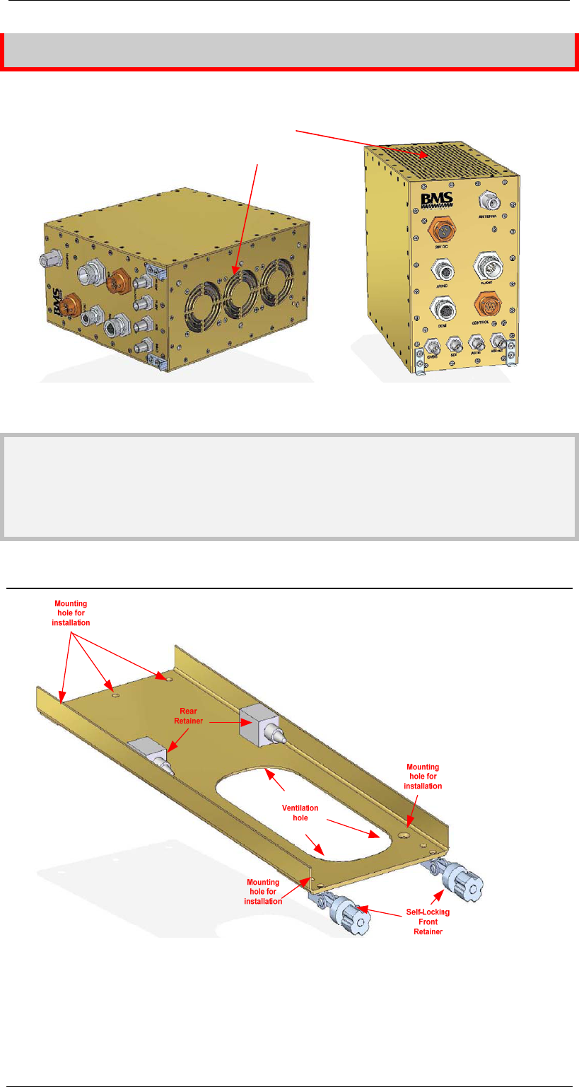
If the unit is to be permanently mounted, active ventilation should be provided.
Figure 1: Ventilation Openings
Note
For helicopter installation it is recommended to use the CT6540ARINC
mounting tray.
3.1 ARINC Mounting Plate
Figure 2: Mounting Plate Overview
The mounting plate disposes of five mounting holes. Two of them are to be found
on the front end, the other three on the back end.
Ventilation opening
Bottom of
CT6540ARINC Front of
CT6540ARINC
8
3 Installing the Transmitter
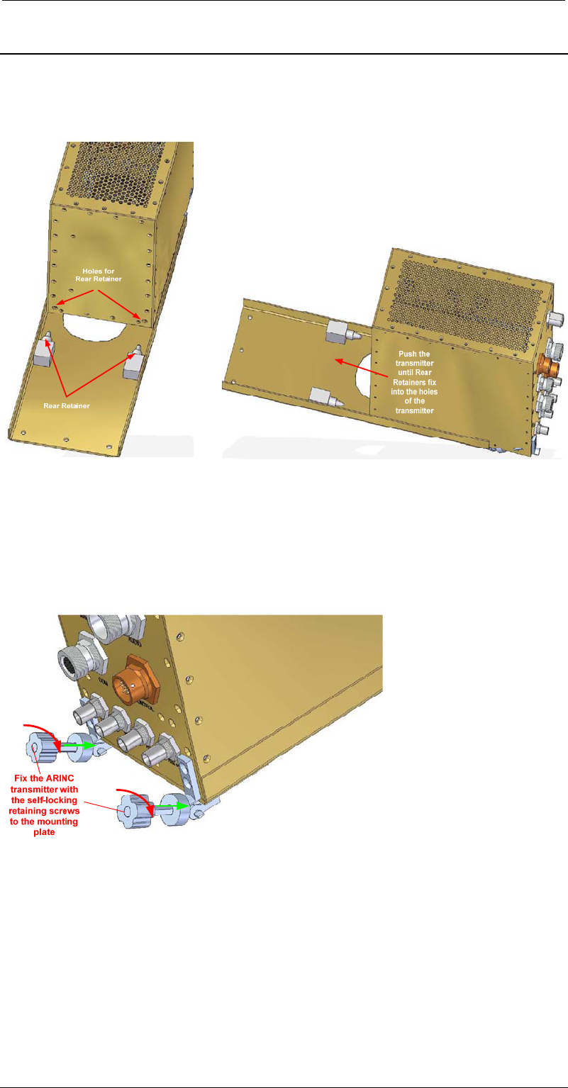
3.2 Mounting Instructions
Fixing the mounting plate
1. Fix the mounting plate to the ground by drilling screws through the mounting
holes.
Figure 3: Retainer Locations
Figure 4: Fixing the Transmitter
Fixing the transmitter to the mounting plate
2. Slide the transmitter into the mounting plate
3. Push the transmitter back until stabilised by the retainers
Figure 5: Locking the Transmitter
4. Lock the transmitter with the retaining screw

9
3 Installing the Transmitte
r
Figure 6: Mounted Transmitter
Cabling the transmitter
Please refer to chapter Connectors Transmitter on page 19 for a detailed
description of the connectors.
Figure 7: CT6540ARINC Connector Panel
5. Connect the antenna to the socket labelled “ANTENNA”
6. Connect the control panel to the socket labelled “CONTROL”
Vibration dam
p
e
r
2
,
5 cm

10
3 Installing the Transmitter
7. Connect available video source to the BNC sockets labelled “CVBS
8. Connect all available audio sources to the connector labelled “AUDIO”
9. Connect optional devices to the output labelled “ASI out” if necessary
10. Connect other devices to the sockets labelled “COM” and “ARINC” if
necessary
Note
The ports “COM” and “ARINC” are subject of customised applications. Please
refer to separate instructions.
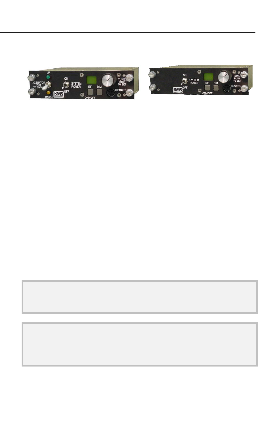
Installing the control panel
There are two types of control panels available. One version controls the antenna
actuator, the other does not.
Figure 8: Control panel connectors (with
actuator control)
Figure 9: Control panel connector
(without actuator control)
11. Connect the antenna actuator cable to the socket labelled “ACTUATOR” if
available
12. Connect the transmitter to the socket labelled “COM”
13. Connect the power supply to the socket labelled “POWER” if available
14. Fix the control panel in the cockpit centre console with the four retaining
screws
15. After all connections are made securely, connect the power supply to the
socket labelled “28V DC” transmitter
Caution
When using a power pack, make sure that the maximum supply current is at
least 8 A and the output voltage matches the input voltage range of the
CT6540ARINC transmitter.
Failure to comply with these requirements may cause fatal damage to the
power pack and/or CT6540ARINC.
You must use original cables. If you have questions please contact BMS
customer service.
CT6540ARINC

11
4 Dismounting the Transmitte
r
Before connecting the 28V DC power supply cable, ensure all other equipment,
esp. the antenna, is connected.
4 Dismounting the Transmitter
Before you start dismounting the system make sure it is powered down. Confirm
that the power switch on the control panel is shifted to position “OFF”.
Unplugging all cables
1. Unplug the power cables of the transmitter and the control panel first
2. Unplug all remaining cables
Remove the components
3. Release the retaining screws of the transmitter and the control panel
4. Remove the control panel and the transmitter
12
5 Controlling the System 3.2 Mounting Instructions
5 Controlling the System
The whole system is controlled through the control panel located in the cockpit.
There are two types of control panels available. One version controls the antenna
actuator, the other does not.
Figure 10: Control panel with actuator
switch Figure 11: Control panel without
actuator switch
INBUILT DISPLAY
The inbuilt display show different configuration parameters, the current
transmitter state, or alarm messages.
ROTARY KNOB
Use the rotary knob to select the different configuration parameters like “CH”,
“SCRAMBL”, and “RF LEVEL”.
Preset selection
1. Press the rotary knob labelled “TUNE” for approximately two seconds
2. Turn the knob until “CH” is shown
3. Press the knob for approximately two seconds
4. Turn the knob until the desired preset number is shown
5. The transmitter loads the settings
6. Press the rotary knob for approximately two seconds to select the loaded
configuration
Note
If you press the rotary knob short the transmitter discards your selection.
Note
The programming of the different presets must be done through a computer and
configuration software.
Scrambling
1. Press the rotary knob labelled “TUNE” for approximately two seconds
2. Turn the knob until “SCRAMBL” is shown
3. Press the knob for approximately two seconds to activate or deactivate
scrambling

13
3.2 Mounting Instructions 5 Controlling the System
4. Press the rotary knob for approximately two seconds to select the loaded
configuration
Note
If you press the rotary knob short the transmitter discards your selection.
Note
If you change the scrambling mode of a preset this is only stored temporarily.
For permanent activation resp. deactivation of scrambling use a computer and
the configuration software.
Power amplifier level
1. Press the rotary knob labelled “TUNE” for approximately two seconds
2. Turn the knob until “RF LEVEL” is shown
3. Press the knob for approximately two seconds to set the level of the power
amplifier to low or high
4. Press the rotary knob for approximately two seconds to select the loaded
configuration
Note
If you press the rotary knob short the transmitter discards your selection.
Note
By default RF power is set to high.
SYSTEM POWER SWITCH
Power on the system
Shift the switch to position “ON”. The display lights up orange during
initialisation phase. After approximately 10 seconds the display lights green.
Note
When switching on the system a valid video (and optionally audio) signal must
be present on the selected input.
Power off the system
Shift the switch to position “OFF”. The display switches off. Now the
CT6540ARINC transmitter is powered off.

14
5 Controlling the System 3.2 Mounting Instructions
RF POWER BUTTON
Power on the power amplifier
When the power amplifier is turned off push the button labelled “RF” to switch
on the power amplifier of the transmitter. The display lights green.
Power off the power amplifier
When the power amplifier is turned on push the button labelled “RF” to switch
on the power amplifier of the transmitter. The display lights orange.
Caution
Before switching on the power amplifier ensure the antenna is connected
properly. Otherwise the transmitter may get damaged.
DIMMING THE DISPLAY
Press the button labelled “DIM” to reduce the brightness of the display.
Note
The control panel is night vision capable per MIL-L85762A and complies with
MIL STD 3009.
ACTUATOR CONTROL (OPTIONAL)
Stow antenna for landing
Shift the switch labelled “ACTUATOR” to the position “UP” in order to move
the antenna to horizontal position and stow the antenna for landing. The
green LED lights up
Bring antenna into flight position
Shift the switch labelled “ACTUATOR” to the position “DOWN” in order to
move the antenna to vertical position. The amber LED lights up. In this
position the best transmission signal is achieved.
Caution
Before landing make sure the antenna is moved into horizontal position.
Otherwise the antenna and/or actuator may get damaged.
Note
The actuator switch is secured. Before shifting pull it slightly and release it from
the interlock.

15
3.2 Mounting Instructions 5 Controlling the System
PROGRAMMING THE TRANSMITTER
The connector labelled “REMOTE” on the control panel is used to connect a
computer through a special cable.
The transmitter is pre-configured by BMS. In case that you desire to modify
the settings of the transmitter please contact BMS customer service.
ALARMS
In case of malfunction those are indicated by the transmitter.
“COM” alarm is shown when the communication between the transmitter and
the control panel is missing. Switch the system off and check all cabling.
“VIDEO FAIL” alarm is shown when no video signal is available on the video
inputs. Check all cabling and make sure your video source is working
properly.
“ANT FAIL” alarm is shown when the antenna is not working properly or not
connected. Check the antenna cabling.
Caution
If there is no antenna connected to the transmitter the system may get
damaged.
“RF FAIL” alarm is shown when the power amplifier does not work properly or
the system is overheating. Make sure cooling air flows properly and the
ventilation openings are not choking.
Note
If the problem persists please contact BMS customer service.
16
6 Technical Specifications 6.3 C-Tick Marking
6 Technical Specifications
Technical specifications of the CT6540ARINC transmitter
6.1 CE Marking
The CE mark is affixed to indicate compliance with the following
directives:
89/336/EEC of 3 May 1989 on the approximation of the laws of the
Member States relating to electromagnetic compatibility.
2006/95/EEC of January 2007 on the harmonisation of the laws of
the Member States relating to electrical equipment designed for use
within certain voltage limits.
Complies with the essential requirements and provisions of the
Directive 1999/5/EC of the European Parliament and of the council of
March 9, 1999 (R & TTE Directive).
6.2 FCC Marking
VFB-CT6540ARI6466
This equipment has been tested and found to comply with the limits
for Class B digital devices pursuant to Part 15 of the FCC Rules and
ICES-003 of industry Canada. This equipment generates, uses, and
can radiate radio frequency energy, and if not installed and used in
accordance with the instruction manual, may cause harmful
interference to radio communications. However, there is no
guarantee that interference will not occur in a particular installation.
If this equipment does cause harmful interference to radio or
television reception, which can be determined by turning the
equipment off and on, the user is encouraged to try and correct the
interference by one or more of the following measures:
• Reorient or relocate the receiving antenna.
• Increase the separation between the equipment and the receiver.
• Connect the equipment to an outlet on a circuit different from that
to
which the receiver is connected.
• Consult the dealer or an experienced radio/TV technician for help.

17
6.4 Safety 6 Technical Specifications
6.3 C-Tick Marking
The C-Tick mark is affixed to denote compliance with the Australian
Radiocommunications (Compliance and Labelling – Incidental
Emissions) Notice made under s.182 of Radiocommunications Act
1992.
6.4 Safety
The equipment has been designed and tested to meet the following standards:
EN 60950
IEC 60950

18
6 Technical Specifications 6.5 Signal Parameters
6.5 Signal Parameters
Frequency Range 6425 - 6525 MHz (P/N 11.2535.100) N male
50
RF Power 5 W (37dBm)
10 W (40dBm)
(switchable)
Video Input CVBS (PAL and NTCS)
BNC
75
Transport Stream Input ASI transport stream (optional) BNC
75
Transport Stream Output ASI transport stream (optional) BNC
75
Audio Input 1x Analogue audio pair in (Line or Mic
Level) +6 dBu
600
Video Coding MPEG-2
Audio Coding MPEG-2 Layer 2
Modulation COFDM, ETS 300744, 2k carriers
Bandwidth 8 MHz
QPSK
16QAM
64QAM
Power Supply 28V DC
Power Consumption < 350 W
Environmental
Conditions
-10°C to +50°C at 5% - 95% humidity
Dimensions (HxWxD) 216mm x 124mm x 250mm
Weight 5.5 kg
Dimensions Control
Panel (HxWxD)
38mm x 146mm x 106mm
Weight Control Panel 0.5 kg
19
6.6 Connectors Transmitter 6 Technical Specifications
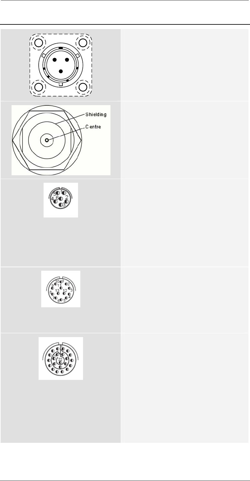
6.6 Connectors Transmitter
A
B
C
Power Input
3-pin SOURIAU (male), 851-02R12-3P50
A. 28V DC
B. GND
C. n.c.
RF output
N connector (female), 50
Centre Signal
Shielding GND
ARINC
D38999-26WA35SN
1. Data TX+
2. Data TX-
3. Data RX+
4. Data RX-
5. GPS Data GND
6. GPS Data RX
Com
D38999-26WA35SN
1. Config Data GND
2. Config Data TX
3. Config Data RX-
4. - 13. Do not use
Audio
D38999-26WC35PN
1. Audio 1L GND
2. Audio 1L+
3. Audio 1L-
4. Audio 1R GND
5. Audio 1R+
6. Audio 1R-
7. - 12. n.c.
13. - 22. Do not use

20
6 Technical Specifications 6.6 Connectors Transmitte
r
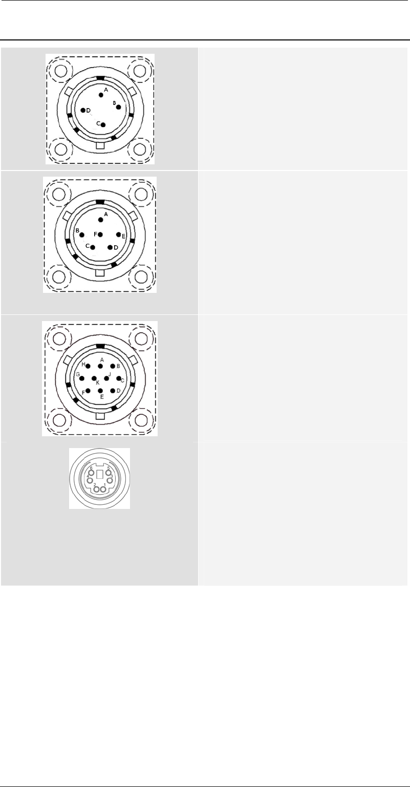
Control Panel
10-pin SOURIAU (male)
A. On/Off A 28V DC out
B. On/Off B 28V DC out
C. n.c.
D. Data RX
E. Data GND
F. Data TX
G. GND 28V
H. RC sense
I. n.c.
J. n.c.
Shieldin
g
Centre
Video input (CVBS, ASI)
BMC connector, 75
Centre Signal
Shielding GND
21
6.7 Connectors Control Panel 6 Technical Specifications
6.7 Connectors Control Panel
Power Input
4-pin SOURIAU (male)
A. 28 - 32V DC
B. Do not connect
C. GND
D. n.c..
Actuator (optional)
6-pin SOURIAU (female)
A. Actuator up indicator
B. n.c.
C. Actuator down command
D. Actuator up command
E. Actuator down indicator
F. n.c.
Transmitter
10-pin SOURIAU (Female)
A. Data RX
B. Data TX
C. GND
D. 5V switched
E. - K- Do not connect
Programming
MD-60SV
1. PC Status
2. PC Command
3. GND
4. RC Busy
5. RC Sense
6. +5V DC
22
6 Technical Specifications 6.8 Cabling and Connectors Overview
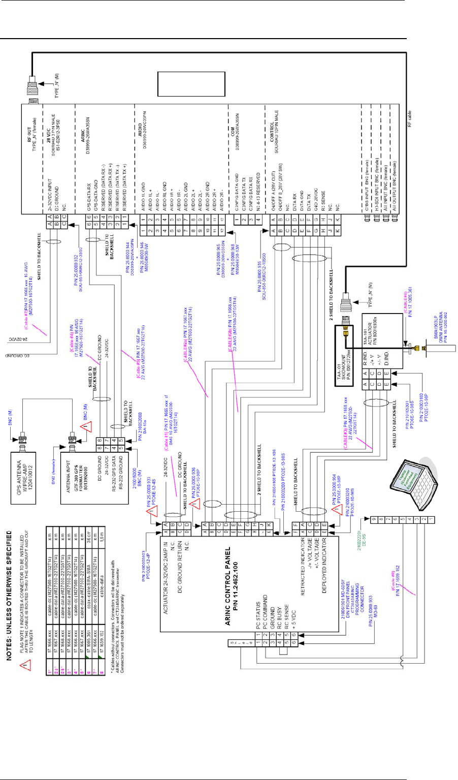
6.8 Cabling and Connectors Overview
Figure 12: Cabling and Connectors Overview
CT6540ARINC
P/N 11.2535.000
23
6.10 Cable CT6540ARINC (CONTROL) to ARINC Control Panel6 Technical Spe
c
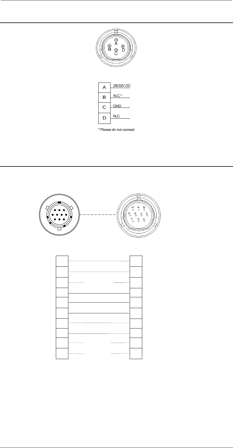
6.9 Cable DC for ARINC Control Panel
Figure 13: DC cabling for ARINC Control Panel (PT06SE-12-4S)
6.10 Cable CT6540ARINC (CONTROL) to ARINC Control Panel
G
H
J
K
To Control Panel
C
D
E
F
A
B
Data RX
Data GND
DataTX
GND 28VDC
N.C
N.C
N.C*
N.C*
From CT2440ARINC
ON/OFF A
(28V out)
PT06SE-10-98P
851-06RC12-10S50
A
B
C
D
E
F
G
H
J
K
cable from Transmitter
to Control Panel
G
H
J
K
C
D
E
F
A
B
ON/OFF B
(28V out)
N.C N.C
RC Sense
Figure 14: CT6540ARINC to ARINC Control Panel cabling
From CT6540ARINC
24
6 Technical Specifications 6.12 Programming Cable for ARINC Control Panel
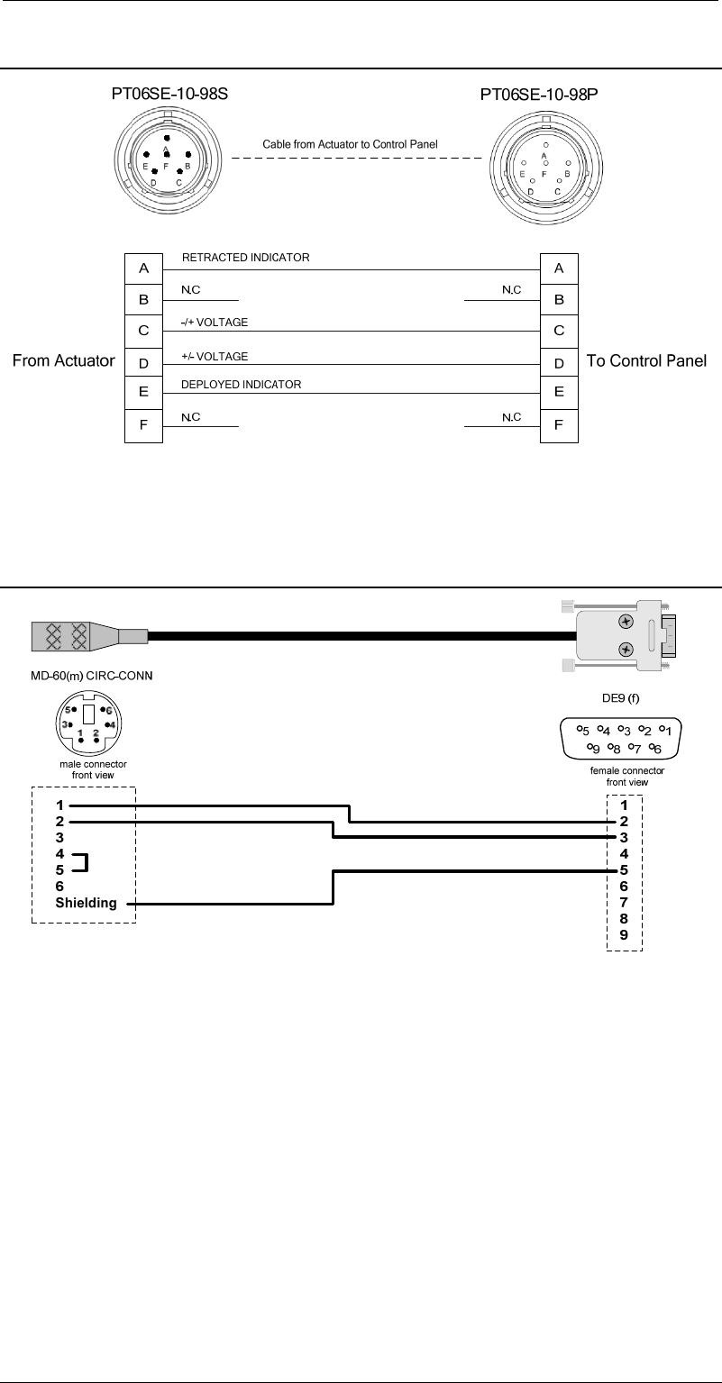
6.11 Cable Actuator to ARINC Control Panel
Figure 15: Actuator to Control Panel Cabling
6.12 Programming Cable for ARINC Control Panel
Figure 16: Programming Cable

25
6.12 Programming Cable for ARINC Control Panel 7 Warranty
7 Warranty
All products and systems of Broadcast Microwave Services Europe GmbH are
designed and built to the highest standards and are covered under a
comprehensive 12 month warranty.
The warranty period starts on the day of delivery ex works Heidenrod. Warranty is
only granted to systems under conditions as supplied to the customer. We do not
support any modified systems. This includes any damage caused by the use of
software not certified by BMS.

27
6.12 Programming Cable for ARINC Control Panel 8 Glossary
8 Glossary
4:2:0
Digital video coding process..
Chrominance levels are sampled in
line alternation mode with reduces
bandwidth.
4:2:2
Digital video coding process..
Chrominance levels of all lines are
sampled with reduces bandwidth.
A
ABS
32-bit ABS encryption standard
AES
Advanced Encryption Standard, a
Federal Information Processing
Standard (FIPS), is an algorithm to
reduce electronic data. It processes
block ciphers.
ASCII
ASCII, American Standard Code for
Information Interchange, a character
encoding scheme.
ASI
ASI, Asynchronous Serial Interface,
is a data format used to carry MPEG
data streams. An ASI stream may
contain one or more video and/or
audio streams.
B
BNC
Bayonet Neill-Concelman, Coaxial
connector.
C
COFDM
Coded Orthogonal Frequency
Division Multiplex is a standard for
terrestrial digital TV transmission.
COMPOSITE
(see DVBS)
CVBS
Colour Video Baseband Signal is an
analogue video signal carrying
colour and luminance information
within one signal.
D
D-ENG
Digital Electronic News Gathering is
a standard for digital video and audio
transmission in the broadcast
industry..
DVB-T
Digital Video Broadcasting
Terrestrial, digital TV transmission
standard.
E
EMC
ElectroMagnetic Compatibility, labels
that electromagnetic devices do not
have a negative impact on other
electromagnetic devices.
ETS
European Telecommunications
Standard
F
FEC
Forward Error Correction, algorithm
used to reduce error rates in digital
data transmission.
FM
Frequency Modulation, analogue
modulation technique.
H
HDMI
High Definition Multimedia Interface
is an interface for digital video.

28
8 Glossary 6.12 Programming Cable for ARINC Control Panel
I
IEC
International Electrotechnical
Committee
IF
Intermediate Frequency, mixes
frequencies up or down to other
frequencies.
ISO
International Standards Organisation
K
KBIT/S
Kilobits per seconds (1000 bits per
second).
L
LINEAR POWER AMPLIFIER
A linear power amplifier amplifies the
output signal of a modulator up to a
level of 1W (appr. 30 dBm).
M
MBIT/S
Megabits per second (1000000 bits
oer second).
MP@ML
Main Profile at Main Level is a part
of the MPEG-2 standards for storage
or transmission of video feeds of up
to 15 Mbit/s
MPEG
Motion Pictures Experts Group is a
standard organisation developing
video compression techniques.
N
NTSC
National Television Systems
Committee is an analogue television
standard mainly used in the USA
and Latin-American countries.
O
OFDM
Orthogonal Frequency Division
Multiplex is bandwidth efficient
modulation technique.
P
PAL
Phase Alternation Line is an
analogue television standard mainly
used in Europe.
PC
Personal Computer
PCM
Pulse Code Modulation is a
technique used to digitize analogue
signals.
Q
QAM
Quadrature Amplitude Modulation is
a modulation technique used to
transmit digital signals.
QPSK
Quadrature Phase Shift Keying is a
modulation technique used to
transmit digital signals..
R
RF
Radio Frequency
RGB
Red, Green, Blue are the primary
colours used in video applications.
RS-232
RS-232 is a serial bi-directional
asynchronous interface for wired
data transmission.

29
6.12 Programming Cable for ARINC Control Panel 8 Glossary
S
SDI
Serial Digital Interface is an interface
for digital video and audio
transmission.
SMA
SubMiniature A is a coaxial
connector used to mount antennae.
S-VIDEO
Separated Video is a video signal
with different signals for luminance
and chrominance.
T
TS
Transport Stream is a data stream
format used by MPEG.
U
USB
Universal Serial Bus is a 4-pole
connection for data transfer between
devices.
V
VDE
Verband Der Elektrotechnik e.V. is a
German association for electrical
and electronic technologies.
X
XLR
XLR (Screen Life Return) is a
connector of three or more poles.
Y
Y/C
Y (luminance) and C (chrominance),
see S-Video.
YUV
YUV is a video signal with different
signals for luminance and
chrominance components

31
6.12 Programming Cable for ARINC Control Panel 9 Index
9 Index
A
About This Reference Guide ........... 1
ABS ............................................... 27
Actuator to Control Panel .............. 25
AES ............................................... 27
ARINC Mounting Plate .................... 8
ASCII ............................................. 27
ASI ................................................ 27
B
BNC ............................................... 27
C
Cabling and Connectors Overview 23
CE Marking ............................... 6, 18
Claims ........................................... 33
COFDM ......................................... 27
Compliance ..................................... 6
COMPOSITE ................................. 27
Connectors Control Panel ............. 22
Connectors Transmitter ................. 20
Contact Information ....................... 33
Controlling the System .................. 14
C-Tick Marking .......................... 6, 18
Customer Support ......................... 33
CVBS ............................................ 27
D
D-ENG ........................................... 27
Designation and P/N ....................... 3
Dismounting the Transmitter ......... 12
DVB-T ........................................... 27
E
EMC .............................................. 27
EMC Compliance ............................ 6
ETS ............................................... 27
F
FEC ............................................... 27
FM ................................................. 27
H
HDMI ............................................. 27
I
IEC ................................................ 28
IF ................................................... 28
Installing the Transmitter ................. 7
ISO ................................................ 28
K
KBIT/S ........................................... 28
L
LINEAR POWER AMPLIFIER ....... 28
M
MBIT/S .......................................... 28
Mounting Instructions ...................... 9
MP@ML ........................................ 28
MPEG ............................................ 28
N
NTSC ............................................. 28
O
OFDM ............................................ 28
P
PAL ................................................ 28
PC ................................................. 28
PCM .............................................. 28
Power Connector ........................... 24
Programming Cable ...................... 25
Q
QAM .............................................. 28
QPSK ............................................ 28
R
Read this first .................................. 1
Registered and General Trademarks
........................................................ 5
RF .................................................. 28
RGB ............................................... 28
RS-232 .......................................... 28
RTCA/DO-160 ................................. 6
S
Safety ............................................ 18
Safety Warnings .............................. 5
SDI ................................................ 29
Signal Parameters ......................... 19
SMA ............................................... 29
S-VIDEO ........................................ 29
T
Technical Specifications ................ 18
Training Courses ........................... 33
Transmitter to Control Panel ......... 24
TS .................................................. 29
U
USB ............................................... 29

32
9 Index 6.12 Programming Cable for ARINC Control Panel
V
VDE ............................................... 29
Versions of this Reference Guide ... 3
W
Warranty ........................................ 26
X
XLR ............................................... 29
Y
Y/C ................................................ 29
YUV ............................................... 29

33
10.3 Claims 10 Contact Information
10 Contact Information
For further information about training courses, technical publications, customer
support request or any other objective please contact BMS Europe at:
Broadcast Microwave Services Europe GmbH
Schwalbacherstraße 12
65321 Heidenrod, Germany
Tel: +49 (6124) 7239 00
Fax: +49 (6124) 7239 29
E-Mail: saleseurope@bms-inc.com
Internet: www.bms-inc.com
10.1 Customer Support
Our primary objective is to provide first class customer care that is tailored to your
specific business and operational requirements. All service levels are supported
by one or more service performance reviews to ensure the perfect partnership
between Broadcast Microwave Services and your business.
10.2 Training Courses
BMS Europe provide a wide range of training courses on the operation and
maintenance of our products and on their supporting technologies. BMS can
provide both regularly scheduled courses and training tailored to individual needs.
Courses can be run either at your premises or at one of our dedicated training
facilities.
10.3 Claims
In the unlikely event of failures on our products please get in contact with our
customer service at your earliest convenience. In case that the equipment has to
be repaired in our repair centre we will provide you with an RMA number.
Please fill out all required information and send the RMA form along with the
failed part to the above given address.