Broadcast Microwave Services CCII-9L 6 GHz Carry-Coder II User Manual
Broadcast Microwave Services Inc 6 GHz Carry-Coder II
user manual
Broadcast Microwave Services, Inc. – 12367 Crosthwaite Circle – Poway, CA 92064
Phone: 800-669-9667, 1-858-391-3050 - Fax: 1-858-391-3049
Email: support@bms-inc.com Web: www.bms-inc.com
Your digital solution for wireless TV production
and terrestrial news gathering.
6GHz CARRY-CODER II
User Manual
Manual Part Number 6051412900 Rev -
Specifications are subject to change without prior notice.
This document contains confidential information and is intended for customer use only.
It cannot be duplicated without prior authorization from BMS.

6GHz CARRY-CODER II
User Manual
6051412900 Rev -

6051412900 Rev - i
GLOSSARY
16QAM Quadrature Amplitude Modulation (16 states)
64QAM Quadrature Amplitude Modulation (64 states)
ATSC Advanced Television Standard Committee
COFDM Coded Orthogonal Frequency Division Multiplex
CVBS Composite Video Baseband Signal
DCE Data Communication Equipment
DVB Digital Video Broadcasting
DVB-T Digital Video Broadcasting for Terrestrial TV
EMC Electro-Magnetic Compatibility
EU European Union
GOP Group Of Pictures
MPEG Moving Pictures Engineering Group
PIN Personal Identification Number
PID Packet Identifier
QPSK Quad Phase Shift Keying
US United States of America
LEGEND
= Idea (Highlighted operator Information)
= Warning (indicates a critical or hazardous point)

6051412900 Rev - ii

6051412900 Rev - iii
CONTENTS
1. OVERVIEW ............................................................................................................................................... 1
2. INFORMATION TO USER....................................................................................................................... 3
3. GETTING STARTED ................................................................................................................................ 5
3.1 Installing the Transmitter on the Camera 5
3.2 Installing the Transmitter in the Backpack 5
3.3 Controlling the CARRY-CODER II Transmitter 6
3.4 Transmitter Operating Configuration 6
3.5 CARRY-CODER II Transmitter <EXPERT> Operating Mode Configuration 7
4. OPERATING INSTRUCTIONS................................................................................................................ 9
4.1 Start-Up Indications 9
4.2 Operator Menu Summary 9
4.3 Changing Operator Menu Parameter Values 12
4.4 Setting Transmitter Operating Frequency 13
4.5 Setting Transmitter Output Power 13
4.6 Setting Transmission Mode and Robustness 13
4.7 Recalling and Saving Operating Configurations 14
4.8 Setting Video Input Parameters and Video Mode 14
4.9 Setting Audio Input Parameters and Audio Level 15
4.10 Configuring Data Input (RS-232) 15
4.11 Configuring Transmission Privacy 16
5. USING EXPERT MODE ......................................................................................................................... 17
5.1 Expert Video Parameters 17
5.2 Expert COFDM Parameters 18
6. INPUT/OUTPUT CHARACTERISTICS ................................................................................................ 21
6.1 Composite Video (CVBS) 21
6.2 Component Video (YUV) 21
6.3 Analog Audio 21
6.4 Data Input 21
6.5 Remote Control Port 21
6.6 RF Output 22
6.7 Power Supply Input 22
7. WARRANTY AND RETURN TO FACTORY....................................................................................... 23
8. CONTACT INFORMATION .................................................................................................................. 24
9. ANNEX A: COFDM Modes Characteristics ........................................................................................... 26
10. PIN OUT INFORMATION.................................................................................................................. 30

Broadcast Microwave Services Inc.
12367 Crosthwaite Circle, Poway, CA 92064-6817
Phone: 858-391-3050. Toll Free: 800-669-9667. Fax: 858-391-3049. Web: www.bms-inc.com
1
WARNING!
RF RADIATION EXPOSURE HAZARD
This warning is provided by Broadcast Microwave Services (BMS) Inc. for safety purpose.
The following information help to reduce the risk of RF exposure hazard.
FCC Limit of RF Exposure
According to Federal Communication Commission (FCC), the Maximum Permissible
Exposure (MPE) for FR radiation has been set to 1.0 mW/cm2 for the 6 GHz Carry-
Coder II with 190 mW output power (OET Bulletin 65).
The 6 GHz Carry-Coder II is a non-broadcast transmitter and without an antenna it will
not create RF exposure (power density) exceeding the 1.0 W/cm2 FCC limit.
However a high-gain antenna such as a parabolic dish will greatly enhance the 6 GHz
Carry-Coder II output power density beyond the MPE limit of 1.0 mW/cm2.
In this situation a minimum distance from the antenna needs to be calculated in order to
keep the MPE always below the safety limit. The calculation has been done for 6 GHz
Carry-Coder II based on the formula mentioned in OET Bulletin 56.
The calculations have been done for different commonly used antenna in the Public
Safety/ Law enforcement applications.
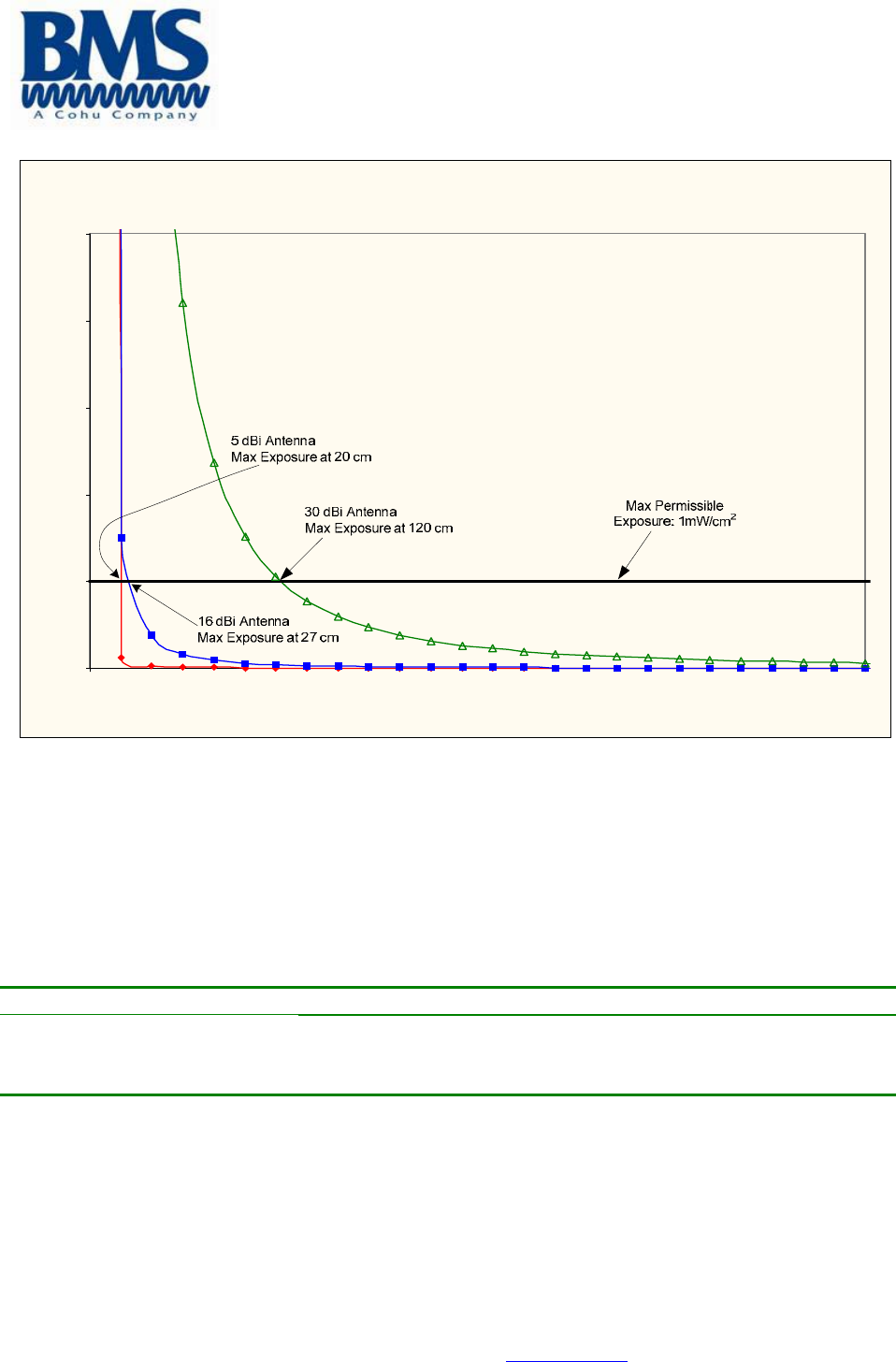
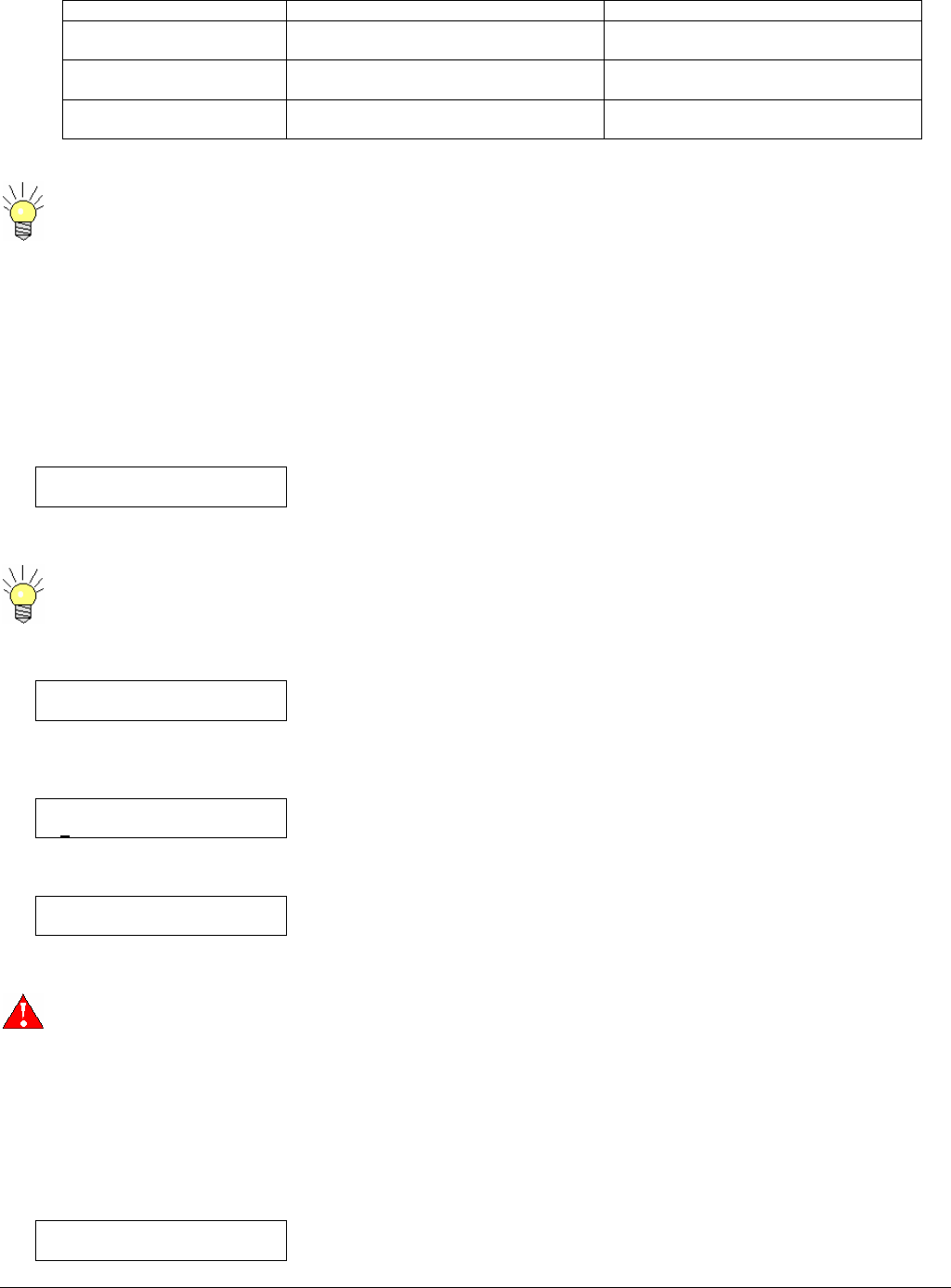
Figure 1 shows the plot of the minimum exposure distance for 5dBi, 16dBi, and 30dBi
antennas. The 6 GHz Carry-Coder II transmits the maximum power of 190 mW. The
minimum exposure distances are found from the cross points of the exposure graphs
(for various antennas) with the line of maximum permissible exposure (i.e. 1 W/cm2).
Notice that the numbers in Figure 1 predict the worse case scenario, which is straight in
front of the antenna (exposing to the antenna main-lobe). Obviously the side-lobe
exposures are well below these numbers as the radiation intensity dramatically reduces
on the side lobes.
"The antenna used for this transmitter must not be co-located or operating in conjunction
with any other antenna or transmitter."
Broadcast Microwave Services Inc.
12367 Crosthwaite Circle, Poway, CA 92064-6817
Phone: 858-391-3050. Toll Free: 800-669-9667. Fax: 858-391-3049. Web: www.bms-inc.com
2
Estimated RF Exposure for 6 GHz Carry-Coder II
0.0
1.0
2.0
3.0
4.0
5.0
0 100 200 300 400 500
Dis tance , cm
Power Density, mW/cm^2
Figure 1
Summary
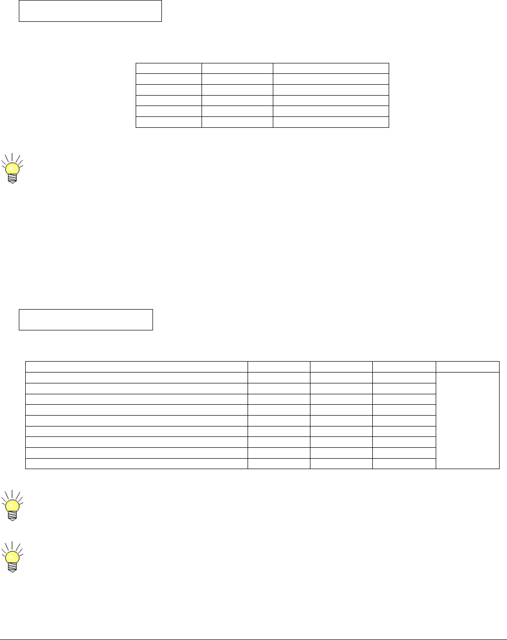
In order the keep the RF exposure within the FCC limit, it is necessary to maintain the
safe distance from the antenna. The results shown in Figures 1 can be summarized in
the following table:
Antenna Gain (dBi) Minimum permissible distance from antenna (cm)
5
16
30
20
27
120
Notice the above table indicates worst-case situation (straight in front of the antenna).
6051412900 Rev - 1
OVERVIEW
Wireless digital communications is increasingly used across the teleproduction community, especially by organization covering news
and sports. The technology of DVB-T is generally adopted because of interoperability and reliable performance provided by MPEG-
2 compression and COFDM.
BMS offers its expertise in the Carry-Coder product family with the high-power Carry-Coder II portable transmitter and companion
COFDM integrated receiver-decoder, the De-Coder II.
The Carry-Coder product family includes:
• CARRY-CODER II: Portable transmitter, dockable to a camera or carried in a custom backpack.
• HELI-CODER II: Transmitter system for aircraft applications.
• DE-CODER II: Rack-mounted COFDM integrated receiver-decoder.
• CARRY DE-CODER II: Portable COFDM integrated receiver-decoder.
• TRUCK-CODER II: Rack-mounted COFDM or Analog transmitter fore ENG applications.
• FIELD-CODER II: Portable COFDM or Analog transmitter designed for tripod mounted applications.
Key features for these products are:
• Robustness
• DVB-T transmission for portable and mobile operation in a multi-path environment.
• High quality, reliable transmission of video and audio in portable and mobile use.
• Flexible audio, video and data interfaces.
• Compact size.
• Low-power consumption.
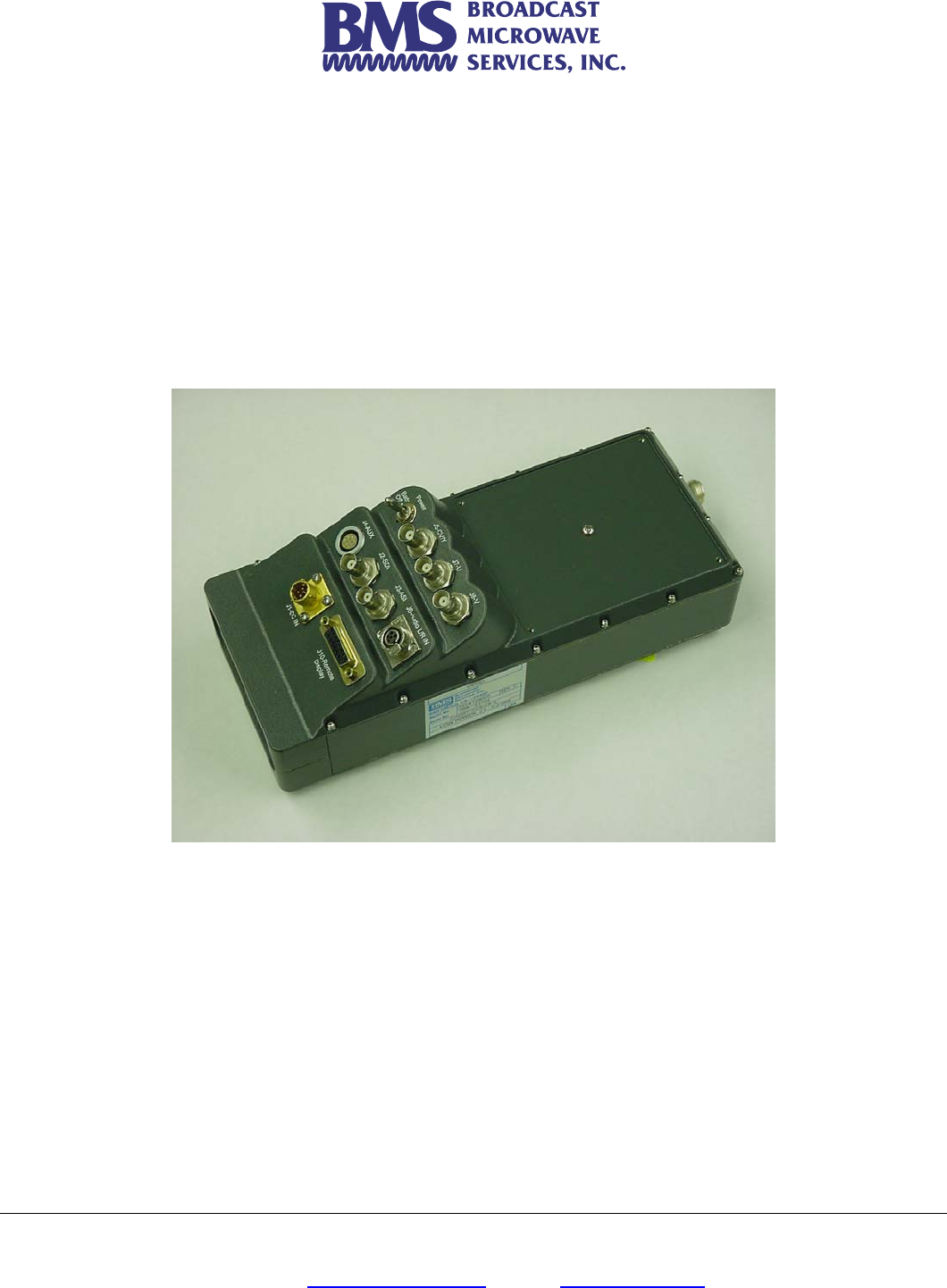
• The CARRY-CODER II is a portable device that performs wireless digital transmission of audio, video and data.
• It can be mechanically docked to the rear of a video camera equipped with a battery socket (Anton/Bauer or Sony).
• It can be carried comfortably in a matching BMS backpack.
• The Carry-Coder II interface consists of video and audio cables.
The following block diagram gives an overview of CARRY-CODER II architecture:
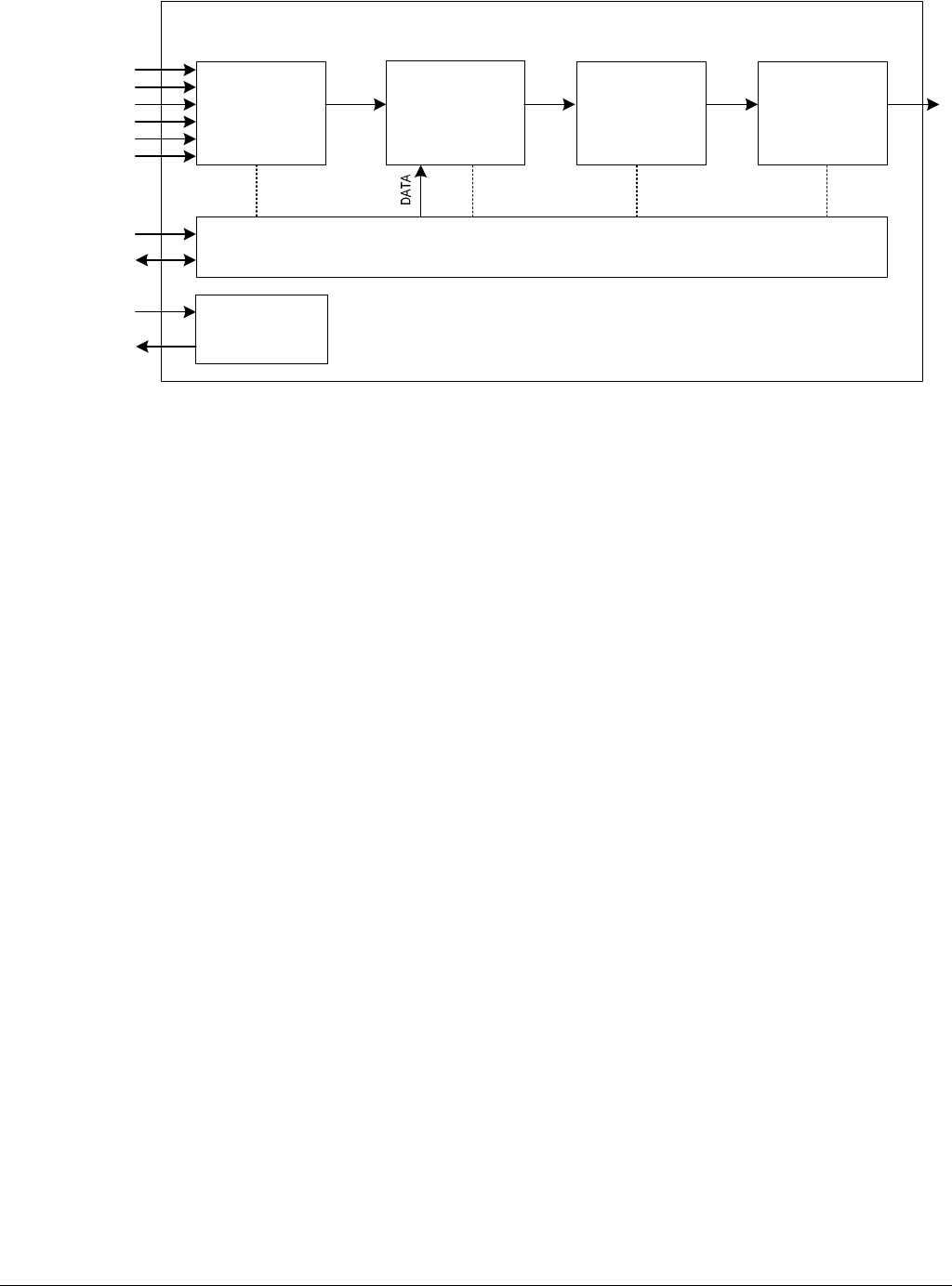
6051412900 Rev - 2
MPEG2
Encoder
(Audio/Video)
DATA Multiplexer COFDM
Modulator
Control Unit
RF Up-
Converter and
Amplifier
Power Supply
Management
+12 to 32 VDC Input
Loop Through
Remote
RS232 (DATA)
RF Output
Carry-Coder II
Y/CVBS In
U In
V In
AL In
AR In
SDI In
The CARRY-CODER II is comprised of the following sub-systems:
• An MPEG-2 Encoder (1 video channel + 2 audio channels) compliant to ISO/IEC 13818 (MP@ML).
• A Data Multiplexer.
• A COFDM Digital Modulator (“2K” sub-carriers) compliant to ETS 300 744 (the DVB-T standard).
• An RF Up-Converter and RF Amplifier (providing up to 1W transmitter output power.
• A detachable hand held remote offering a user-friendly displayed interface for control and system status.
The CARRY-CODER II includes the following input/output connections:
• Composite video input (CVBS)
• SDI input
• Component video input (YUV)
• Analog audio line inputs (L+R)
• ASI Input
• 1 RS232 data interface (for user applications)
• 1 remote control port
• 1 RF output port
• 1 power supply input (11-32VDC nominal)
• 1 battery docking connector with “loop-through” power output.

6051412900 Rev - 3
Changes or modifications not expressly approved BMS, Inc. could void the user's authority to operate the equipment.
INFORMATION TO USER
This device complies with Part 15 of the FCC Rules. Operation is subject to the following two conditions: (1) This device may not
cause harmful interference, and (2) This device must accept any interference received, including interference that may cause
undesired operation.
This equipment has been tested and found to comply with the limits for Class B Digital Device, pursuant to Part 15 of the FCC
Rules. These limits are designed to provide reasonable protection against harmful interference in a residential installation. This
equipment generates and can radiate radio frequency energy and, if not installed and used in accordance with the instructions, may
cause harmful interference to radio communications. However, there is no guarantee that interference will not occur in a particular
installation. If this equipment does cause harmful interference to radio or television reception, which can be determined by turning
the equipment off and on, the user is encouraged to try to correct the interference by one or more of the following measures.
Reorient or relocate the receiving antenna
Increase the separation between the equipment and receiver
Connect the equipment into an outlet on a circuit different from that to which the receiver is connected
Consult the dealer or an experienced radio/TV technician for help
Any changes or modifications not expressly approved by BMS, Inc. could void the user’s authority to operate the equipment.

6051412900 Rev - 4

6051412900 Rev - 5
GETTING STARTED
Installing the Transmitter on the Backpack
• Orient the CCII so that it will mount onto the backpack with the Antenna facing up.
• Align the three mounting pins on the back of the CCII with the receptacles on the backpack.
• Slide the CCII into to the receptacle until it is locked in place. No orange will show from under the latch.
• Use the belt to further secure the CCII in place.
• Carefully attach the BMS supplied antenna with integrated extension shaft to the antenna connector on the top of the
CARRY-CODER II. This antenna extension shaft ensures that the transmitted signal is sent out into unobstructed space for
propagation of the COFDM signal. In addition this shaft ensures the safety of the operator in accordance to FCC and CE
safe emissions requirements.
• Connect the interface cables from the camera to the appropriate CARRY-CODER II connector(s).
Installing the Battery on the Backpack
• Slide the battery in to the receptacle located underneath the CCII until it locks into place
• Connect the power cable coming from the backpack battery connector socket to the CARRY-CODER II.
• Switch on the power for the camera and the CARRY-CODER II.
When the CARRY-CODER II is used in the camera mount or the backpack configuration the system must be used
with the BMS supplied antenna that has an integrated shielded antenna extender in order to meet FCC and CE safe
emissions requirements.
Please note that the CARRY-CODER II can be powered from an external supply source (i.e., a battery belt or the
backpack battery) instead of an attached battery. For this purpose, the CARRY-CODER II provides a separate power
connector and a switch to select the docked battery or a separate DC power source. The benefit provided by using
the backpack is the efficient use of individual batteries, obtaining optimal battery life.
6051412900 Rev - 6
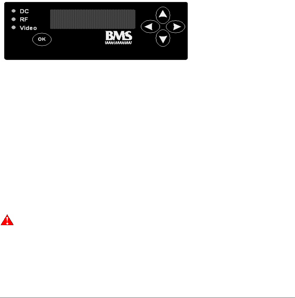
Controlling the CARRY-CODER II Transmitter
Control Unit Features
• The CARRY-CODER II control unit is designed for the convenience of the user.
• The control unit can be attached or disconnected at any time.
• Easily readable four line display.
• Operator navigation of menu with four intuitive directional buttons.
• Operational command entry using the <OK> button.
• Display includes status icons at right portion of top line.
• Text menu line one displays operating frequency.
• Text menu lines two and three are for system control functions.
• Text menu line four displays system status.
Transmitter Operating Configuration
When the CARRY-CODER II is powered up for the first time, the operator can easily review the operating parameters using the
control unit. Here is a listing of the parameters, in operating menu sequence.
• RF Output Operating Frequency (.25 or .5 MHz Steps depending on Frequency or BAS Band Channel with Operating
Frequency).
• RF Output Power (OFF LOW MID HIGH MAX).
• Transmission Mode Robustness (LOW MID HIGH).
• Recall Configuration (Presets 1 to 9).
• Save Configuration (Presets 1 to 9).
• Video Input (CVBS, YUV, ASI, SDI).
• Video Mode (PAL, NTSC).
• Audio Input (analog, AES, SDI).
• Audio Level Left
• Audio Level Right
• Data Port Baud Rate (1.2, 4.8, 9.6 Kbps)
• Encryption (OFF or PIN code entry).
• User Mode (NORMAL, EXPERT)
PLEASE THOROUGHLY REVIEW SECTION 0 BEFORE USING <EXPERT> Mode.

6051412900 Rev - 7
CARRY-CODER II Transmitter <EXPERT> Operating Mode Configuration
NOTE: Most users will operate the system in <NORMAL> mode. The <EXPERT> mode provides user control of certain DVB-T
parameter settings. Here is a listing of those parameters in operating menu sequence:
• Resolution (1/1, 3/4, 2/3, 1/2)
• GOP Structure (I, IP, IBP, IBBP, 422IBBP)
• GOP Length (6, 12, 18, 24)
• Constellation (QPSK, 16QAM, 64QAM)
• Guard Interval (1/32, 1/16, 1/8, 1/4)
• Code Rate (1/2, 2/3, 3/4, 5/6, 7/8)
Please refer to Section 4.6 for a table describing how these DVB-T parameters are applied to the three factory presets for signal
robustness.
Section 0 contains operating instructions for using the EXPERT mode.
Certain operating parameters are used on a repeated basis. These settings should be stored in memory as
Configuration Presets 2 through 9. This provides fast restoration of parameter settings that are used most often.
A good backup plan is to maintain commonly used parameter settings (i.e., high robustness and maximum power) in a
known configuration preset memory. If a problem occurs that won’t go away, a known good parameter setting can be
recalled from memory. This should help to resolve a problem. Another method is to adjust each parameter one by
one, beginning with changing the operating frequency, to ensure that the link is not being affected by another signal
on your selected operating frequency.
The <DEFAULT> option in the RECALL CONFIGURATION Menu will set all the parameters of the CCII to the factory
defaults.

6051412900 Rev - 8
6051412900 Rev - 9
OPERATING INSTRUCTIONS
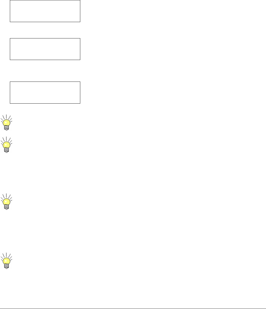
Start-Up Indications
The CARRY-CODER starts with display showing the status of the system During system initialization, the CARRY-CODER II goes
through self-test of its MPEG-2 encoder, COFDM modulator and RF sections. System initialization 10 seconds and will display as
follows:
BMS Inc. CarryCoder 2
Freq Agile 6425 – 6526 MHz
Software Ver. 2.01
Resetting /
At the completion of the initialization process, the display should look like this:
6431.25 MHz
FREQUENCY
6431.25 MHz
If the self-test finds that a sub-system does not respond correctly, a status message is displayed on the fourth line of the display.
For example, if the camera is not sending video to the transmitter, the display will include the appropriate message:
6431.25 MHz
FREQUENCY
6431.25 MHz
NO VIDEO
When the CARRY-CODER starts up, it is in the same condition as when it was powered down. This allows the user to
replace the battery with no need to touch the controls.
The CARRY-CODER II will not transmit with out video. If the System is powered up without video, the CARRY-
CODER II will automatically reboot once video input starts. The CARRY-CODER II will transmit with ASI.
Operator Menu Summary
When the control panel display shows normal system status (no Error or Warning status message) and if there is no operator use of
the control panel, the display goes dark to save battery life. Pressing any key on the control unit restores the display to show the
status of the system.
If there is a status message, the display will remain lit (will not go dark) until the problem is resolved.
The user menus can be accessed from the status screen by pressing any key. Then, the user can scroll the menus by pressing the
« Ç » and « È » keys.
After 30 seconds of keypad inactivity, the display automatically returns to the status screen.
Pressing the « Ç » and « È » keys simultaneously will cause the display to go to the status screen without having to
wait 30 seconds.

6051412900 Rev - 10
Carry-Coder II Operating Menu Structure
FREQUENCY
6431.25 MHz
RF OUTPUT POWER
off low mid high max
ROBUSTNESS
low mid high expert
RECALL CONFIGURATION
1 2 3 4 5 6 7 8 9 default
SAVE CONFIGURATION
1 2 3 4 5 6 7 8 9
VIDEO INPUT
CVBS YUV SDI ASI
VIDEO MODE
PAL NTSC
AUDIO INPUT
analog SDI
AUDIO LEVEL LEFT
-9--------0+++4
AUDIO LEVEL RIGHT
-9--------0++++4
DATA PORT BAUD RATE
1.2 4.8 9.6
ENCRYPTION
OFF enter PIN
USER MODE
normal expert

11
CARRY-CODER II EXPERT Operating Menu Structure
Video bitrate
4.35 Mbps
GOP STRUCTURE
I IP IBP IBBP 422 IBBP
GOP LENGTH
6 12 18 24
CONSTELLATION
QPSK 16QAM 64QAM
GUARD INTERVAL
1/32 1/16 1/8 1/4
CODE RATE
1/2 2/3 3/4 5/6 7/8
Channel Bandwidth
8 7 6 Mhz
Serial Address
6
Encryption Type
A B
Video PID
300
Audio PID
301
PCR PID
101
PMT PID
200
6051412900 Rev - 12
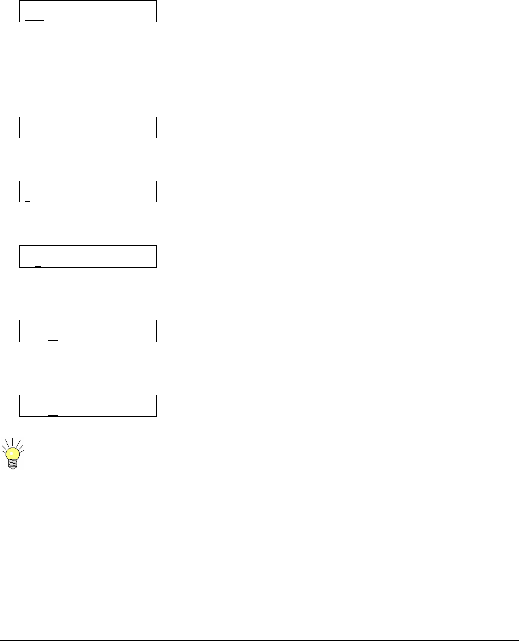
Changing Operator Menu Parameter Values
When changing an operating parameter, line 2 describes the parameter and line 3 offers the available choices:
RF OUTPUT POWER
OFF LOW MID HIGH MAX
The cursor (underscore) shows that the transmitter output is switched off. The operator can change the current condition (displayed
line 3) by using the Left Arrow < Å > or Right Arrow < Æ > keys, moving the cursor under the desired transmit output power level,
followed by pressing the < OK > key to accept the chosen parameter. If the user doesn’t confirm his choice by pressing the < OK >
key, or uses the Up Arrow < Ç > or Down Arrow < È > keys, the operating parameter change is cancelled; the current parameter is
not modified. This is a convenient “escape” feature.
Certain operating parameters are entered values (not selected values). For example, the frequency is displayed as follows:
FREQUENCY
6434.50 MHz
To change the current value of this parameter, the operator presses < OK >, entering the Menu Edit mode, so the cursor appears
under the first figure of the displayed frequency, as follows:
FREQUENCY
6434.50 MHz
The frequency value is changed by the following steps: (1) move the cursor to the appropriate figure using the < Å > and < Æ >
keys; (2) increment or decrement the selected figure using the < Ç > and < È > keys. For example:
FREQUENCY
6434.50 MHz
The frequency value to the right of the decimal point is a fractional MHz value, selected in steps of 250 KHz (.25 MHz). Repeat the
operation (previously described) to increment or decrement this value. To increment to a frequency of 2450.50 MHz, move the
cursor to the right of the decimal point, then press the < Ç > one time:
FREQUENCY
6454.50 MHz
After modifying all of the necessary digits, the operator must validate the chosen frequency by pressing < OK > and closing the
Menu Edit mode, changing the operating frequency.
FREQUENCY
6454.25 MHz
If you make a mistake while setting a number and you want to restore the previous value, don’t validate your
modifications: simply wait during 30 seconds without touching the keypad. The system will automatically exit the edit
mode without saving the modifications; the display returns to the status screen.
6051412900 Rev - 13
Setting Transmitter Operating Frequency
CARRY-CODER II Using Direct Frequency Entry
The RF frequency is set as follows:
6454.25 MHz Ψ ▌▌▌▌
FREQUENCY
2454.25 MHz
The frequency display is expressed in MHz with 250 kHz tuning steps. The frequency value corresponds to the center of the 8 MHz
RF channel that is used for transmission. If the user tries to enter a value which is not in the operating frequency range, an “Out of
range” message is displayed and the current frequency value is not changed.
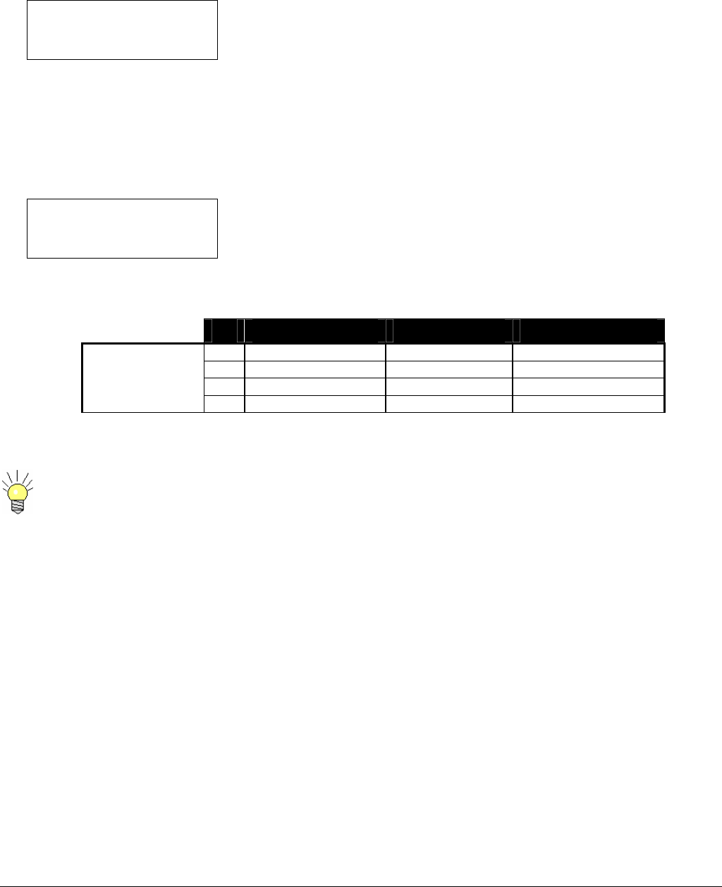
CARRY-CODER II for Broadcast
The RF operating frequency is set using the channel plan with frequency offset.
CH 3- 2029.25 MHz
FREQUENCY
2029.25 MHz
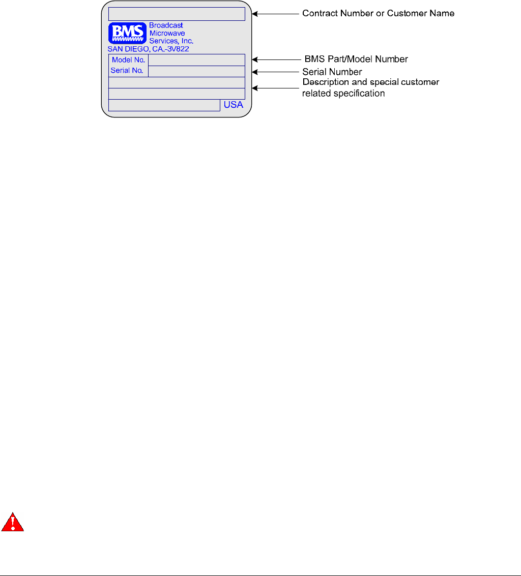
Versions of the CARRY-CODER II are available for several dedicated operating frequency ranges. Refer to the serial identification
plate for the specific frequency range for your CARRY-CODER II. These are the US channels table and corresponding frequencies.
Ch - (0) +
A 6431.25 6437.5 6443.75
B 6456.25 6462.5 6468.75
C 6481.25 6487.5 6493.75
6 GHz Channel
Plan
Low Band
6425-6525 MHz D 6506.25 6512.5 6518.75
The CARRY-CODER II will not transmit without video. The CARRY-CODER II will reinitialize once video signal
begins.
6051412900 Rev - 13
Setting Transmitter Output Power
The RF power is set through the following menu:
RF OUTPUT POWER
off low mid high max
The following table gives the RF power (real average COFDM power) corresponding to each setting, accompanied by the resulting
power supply consumption. (2 GHz shown)
Choice RF Power Power Consumption
OFF Muted Low (about 30 W)
LOW 25 mW Low (about 30 W)
MID 50 mW Low (about 30 W)
HIGH 100 mW Normal (about 40 W)
MAX 250 W Normal (about 40 W)
When the CARRY-CODER II is close to the receiving antenna (< 25m) you can try to reduce the RF output power to
MIN or MID level. It saves the batteries and can improve reception (avoiding receiver overload).
Setting Transmission Mode and Robustness
The CARRY-CODER II includes 3 pre-defined modes, characterized by defined transmission robustness.
These 3 pre-defined modes have been configured to provide the best trade-off between transmission robustness, video quality and
end-to-end delay for typical applications of the CARRY-CODER.
These modes can be selected through the following menu:
ROBUSTNESS
low mid high expert
The detailed characteristics of these modes are:
Mode (Tx Robustness) LOW MID HIGH EXPERT
COFDM Guard Interval 1/16 1/8 1/16
COFDM Constellation 64QAM 16QAM QPSK
COFDM Code Rate 1/2 ½ 1/2
Video bit rate (Mbps) 15.0 11.0 4.9
Audio bit rate (kbps/channel) 192 128 128
Resolution 720 x 576 720 x 576 720 x 576
GOP structure IP IP IP
GOP size 12 12 12
End to end delay (ms) 130 ms 130 ms 130 ms
As configured
individually
through the
“Expert” User
Mode
When changing to the < HIGH > robustness condition, take the following steps.
1. Select < HIGH > mode then press < OK >
2. Wait for the system to re-initialize then press < OK > once again.
Selecting EXPERT will not change any current settings. It will bring up the EXPERT Mode Menus.
The following table suggests which factory defined robustness mode to use for certain applications.
6051412900 Rev - 14
Mode (TX Robustness) Preferred applications Characteristics
LOW Studio Short transmission range.
Maximum video quality.
MID News, sports, entertainment Medium transmission range.
High video quality.
HIGH Mobile & airborne transmission (with
walls or buildings in the path)
Long and/or difficult transmission.
Normal video quality.
The operator can define specific operating parameters (compression and transmission) via the EXPERT mode. See
section 0
Recalling and Saving Operating Configurations
The CARRY-CODER II provides the operator with the ability to save and recall 8 user-defined presets configurations. These
configurations are non-volatile (saved in an EEPROM) and are not lost when the system power is switched off. Each configuration
contains all of the CARRY-CODER operating parameters, so that recalling a user-defined configuration will restore the system
exactly in the same state as when it was saved.
Preset (stored) configurations are recalled using the following menu:
RECALL CONFIGURATION
1 2 3 4 5 6 7 8 9 default
To recall a configuration the user should select one of the preset memories or default then press < OK >.
Selecting the <default> will reset all settings back to the factory default.
Custom configurations are saved to memory using the following menu:
SAVE CONFIGURATION
1 2 3 4 5 6 7 8 9
To save a configuration the user should first set the appropriate operating parameters to the desired state, then select one of the
preset (configuration) memories locations. In the following example, preset memory 2 is selected.
SAVE CONFIGURATION
1 2 3 4 5 6 7 8 9
Then, press < OK > to save the configuration to the selected preset (memory): The Menu Edit mode is completed.
SAVE CONFIGURATION
1 2 3 4 5 6 7 8 9
.
Be careful when recalling configurations: If a preset configuration includes RF OUTPUT POWER active, the CARRY-
CODER II finishes its initialization and transmits on the RF frequency that is saved in memory! In order to follow
accepted practice and to avoid unwanted transmission, good practice recommends that the preset configurations are
saved with the <RF Output Power> setting in the < OFF > condition.
Setting Video Input Parameters and Video Mode
The video input type is set through the following menu.
VIDEO INPUT
CVBS YUV SDI ASI
6051412900 Rev - 15
The operator can choose:
• CVBS : Composite Video Baseband Signal
• YUV : Component video
• SDI: Serial Digital Video
• ASI: Transport
If there is no signal on the selected input, the CARRY-CODER II displays a “No video” warning message and will not
transmit.
The video input standard is set through the following menu.
VIDEO MODE
PAL NTSC
The user can choose between:
• PAL (625 lines, 50 Hz)
• NTSC (525 lines, 60 Hz)
Setting Audio Input Parameters and Audio Level
The audio input mode is set through the following menu:
AUDIO INPUT
analog SDI
Operator choice includes:
• ANALOG: analog audio (line level)
• SDI:
The Operator can adjust the left and right audio level from –10 dBu to +4 dBu, via the following menus:
AUDIO LEVEL LEFT
+ 3 dBu
AUDIO LEVEL RIGHT
- 6 dBu
For instance, setting a value of –6 dBu means that the CARRY-CODER II is adjusted for a nominal input level of -6 dBu. This
ensures headroom for A:D (analog-to-digital) conversion of approximately 18 dBFs (relative to full scale).
When the nominal audio input level is below the value that is set, the system will operate correctly, but the signal-to-noise ratio will
be degraded and the nominal audio output level on the receiving side will, in like manner, be low.
If the nominal audio input level exceeds the set value, expect digital clipping to occur.
If the nominal audio input level exceeds the absolute maximum value of +4 dBu, the audio signal will be heavily
clipped and there will be significant loss of audio quality.
Configuring Data Input (RS-232)
The CARRY-CODER II provides an RS-232 input port that can be used for asynchronous user data transmission (i.e. for sending
the transmitter’s GPS-derived location data to a receiver tracking antenna system).
The RS-232 input is configured through the following menu:
DATA PORT BAUD RATE
1.2 4.8 9.6

6051412900 Rev - 16
Configuring Transmission Privacy
The CARRY-CODER II offers the choice of encrypting the transmitted signal in order to ensure the privacy of the link. This feature
is controlled through the following menu:
ENCRYPTION
OFF ENTER PIN
This operation uses a 6 digit encryption code. Both the transmitter and the receiver must have the same PIN encryption code in
memory. If not, the DC II receiver will indicate <BAD ENCRYPTION>. The receiver will demodulate the signal, but it will not provide
valid audio, video or data outputs. Once an encryption code is stored, the operator cannot read the setting of the code: if the code is
not on record, the operator must change to a new encryption code or set Encryption to < OFF >.
To activate signal encryption, the operator selects this menu function then presses < OK > to enter the Menu Edit mode. Move the
cursor to ENTER PIN. Press < OK >. The digits available for the CARRY-CODER II encryption code are 0-9, and A-F.
The PIN code is only visible when you enter it. If you forget the PIN code of one device, the simplest solution is to
enter a new PIN code for both the transmitter and the receiver. All six digits set to < 0 > result in no encryption.
The (first generation) CARRY-CODER I (CC I) and the DE-CODER I (DC I) receiver use four digit PIN encryption of 0-9. When the
CARRY-CODER II transmitter is used with the DE-CODER I receiver, the CARRY-CODER II encryption is compatible if the PIN
encryption setting has the first two PIN digits set to <0> (i.e., PIN setting <001234> on the CC II or DC II will work with PIN setting
<1234> on the CC I or the DC I>. Any letters used in a CCII encryption code will be interpreted as 0 by the CCI or DCI systems.
6051412900 Rev - 17
USING EXPERT MODE
The CARRY-CODER II has two modes of operation.
1. The NORMAL mode provides the operator with control of system functions that are needed in routine portable camera
situations. Section 3 of this manual describes these functions, including three factory preset configurations.
2. The EXPERT mode enables the operator to selectively adjust key (audio and video) compression and COFDM
transmission parameters.
The EXPERT mode should be used carefully because specific parameter settings are required to ensure proper
operation of the system. This mode should be reserved to advanced users.
The expert mode is activated through the following menu:
USER MODE
normal expert
The Expert Mode gives access to the expert audio-video and COFDM parameters that are described in the next sections.
Expert Video Parameters
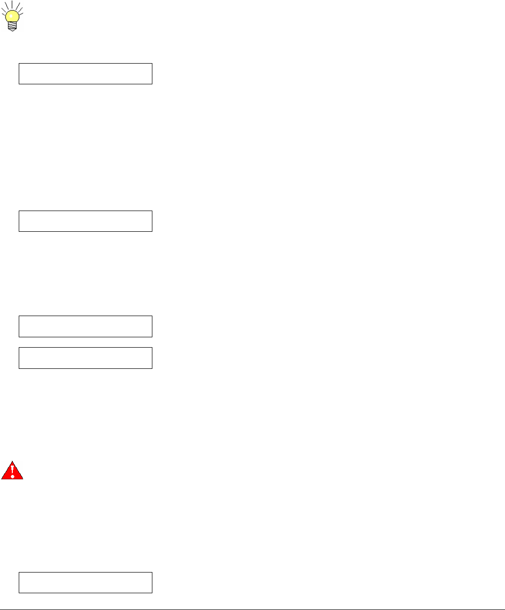
Recommendations
The video quality mainly depends upon the allocated video bit rate and is closely linked to picture resolution and Group Of Picture
(GOP) structure.
The following table describes recommendations for realistic combinations for video encoding parameters.
Video Bit Rate GOP structure Video quality Typical end-to-end Delay
2-3 Mb/s IBBP Poor Approximately 260 ms.
3-5 Mb/s IBBP Medium Approximately 260 ms.
5-8 Mb/s IBBP High Approximately 260 ms.
8-11 Mb/s IP High Approximately 130 ms.
11-15 Mb/s I Maximum Approximately 80 ms.
Other combinations can be derived by the operator using the expert video parameters that are described below:
If the video bit rate selected exceeds the current available bit rate, the CCII will automatically scaled down the bit rate.
Video Bitrate
Video bitrate
4.35 Mbps
This parameter controls digital picture resolution (pixels per line) used for MPEG-2 encoding. A high MPEG-2 encoding Bit rate
provides greater resolution for the best video quality. A low MPEG-2 encoding Bit rate provides lower resolution, reducing the
quality of the picture. Decreasing the resolution setting is useful for a low encoding Bit rate in order to reduce Pixelization when
dealing with highly detailed fast moving scenes.

6051412900 Rev - 18
GOP Structure
GOP STRUCTURE
I IP IBP IBBP 422IBBP
This parameter controls the structure of picture groups used in the MPEG-2 encoding process. These groups are based on three
possible picture types:
• I: Intra-frames (completely encoded).
• P: Predicted-frames (using motion estimation).
• B: Bi-directionally estimated frames (using motion estimation).
This parameter has a direct affect on video encoding delay. For a given Bit rate:
• IBBP and IBP frame modes offer good video quality in difficult transmission conditions.
• IP frame mode offers a good compromise between video quality and “near-line-of-sight” conditions.
• I-frame mode offers the same encoding delay as IP mode, with high Bit rates to ensure the greatest video quality.
GOP Length
GOP LENGTH
6 12 18 24
This is a secondary parameter involving a trade-off between video encoding efficiency and transmission error tolerance. A high
value slightly improves the video quality at the expense of an increased worst-case recovery time required by the MPEG2 decoder
when a transmission error occurs.
The value is expressed in terms of full frame pictures. The typical value is 12.
Expert COFDM Parameters
You can find some information about COFDM modes characteristics in Annex A.
The COFDM mode is controlled by adjusting certain COFDM parameters, described below.
Constellation
CONSTELLATION
QPSK 16QAM 64QAM
This represents the constellation scheme that is used to individually modulate each sub-carrier of the COFDM signal. The
Constellation can be set to optimize robustness but also affects the data transmission rates. QPSK will provide the greatest
robustness but lowest data rates. 16QAM is somewhat robust with a faster data rate. 64QAM will provide the least robust signal,
but at the fastest data rate.
The characteristics corresponding to the 3 possible choices are summarized in this table:
Constellation # of points # of bits
per Sub-carrier
Relative
Bit rate
QPSK 4 2 x 1
16QAM 16 4 x 2
64QAM 64 6 x 3

19
Guard Interval
GUARD INTERVAL
1/32 1/16 1/8 1/4
The Guard Interval corresponds to the idle time that exists between each COFDM symbols, in order to avoid inter-symbol
interference in a Multipath environment. The Guard Interval helps prevent the receiver from being affected by signal echo
interference by allowing time for echoes to settle before the active symbol is sent. Guard Interval is expressed as the ratio of the
idle time divided by the useful part of the COFDM symbol.
Code Rate
CODE RATE
1/2 2/3 3/4 5/6 7/8
The Code Rate represents the ratio of signal to error correction. The Code Rate is related to the quantity of redundancy bits that are
added for error correction. The code rate is expressed as the ratio of the useful bitrate divided by the total bitrate (including
redundancy bits).
Channel Bandwidth
Channel Bandwidth
8 7 6 Mhz
The CCII is capable of 3 channel bandwidth settings.
Serial Address
Serial Address
6
For the typical application, the CCII is controlled by the Handheld Controller (BMS P/N 8014154000) and there is no reason to
configure the serial address. However, It is possible to control the CCII with another external device via the DB15 connector. In that
case, the serial address will need to be configured to match the device used.
When used in an BMS HCII system, the CCII Serial Address must be set to 5
Encryption Type
Encryption Type
A B
CCII uses a proprietary encryption scheme that will only work with BMS recieivers. The Encryption Type only matters when
Encryption is in use. To use Encryption, a PIN must be set (see section 0). This PIN must match the Receiver PIN in order for the
signal to be descrambled. Select the Encryption type based on the application. Type A is recommended encryption type and can
be used for both Telecom or RF broadcast applications. Type B is for RF broadcast only under certain circumstances.
6051412900 Rev - 20
PIDs
You can find some information about Tables and PIDs in Annex B.
The contents of the Transport Stream are defined by information tables that describe the organization of the transmitted data in
addition to the video and audio content. These tables along with video, audio and private user data are transmitted in packets. A
Packet Identifier (PID) number is used to distinguish between packets. PIDs may have values from 0 to 8191.
The CCII allows the following PIDs to be changed:
PMT (Program Map Table) PID
PCR (Program Clock Recovery) PID
Video PID
Audio PID
The PID value set on the CCII must match the PID value on the DCII or CDCII. Mismatched PIDs
will result in no video or audio outputs.
PMT PID
PMT PID
200
Program Map Table Packet Identifier yields information about the Program, Video PID, Audio PID, and PCR PID. The PMT PID
default is 200 for BMS systems.
PCR PID
PCR PID
101
Program Clock Reference Packet Identifier default is 101 for BMS systems.
Video PID
Video PID
300
The Video Packet Identifier default for the BMS systems is 300.
Audio PID
Audio PID
301
The Audio Packet Identifier default for the BMS systems set to 301.

6051412900 Rev - 21
INPUT/OUTPUT CHARACTERISTICS
Composite Video (CVBS)
Type Composite Video Baseband Signal (CVBS)
Systems NTSC 525 lines / 60 Hz / Fsc = 3.58 MHz
PAL 625 lines / 50 Hz / Fsc = 4.43 MHz
Standard ITU-R BT 470-6
Impedance 75 Ohms
Component Video (YUV)
Type YUV (formerly Y / Pb / Pr)
Systems NTSC 525 lines / 60 Hz
PAL 625 lines / 50 Hz
Standard ITU-R BT 470-6
Impedance 75 Ohms
Analog Audio
Type Balanced Line
Channels 2 separate channels (Left and Right)
Nominal input level Adjustable from –10 dBu to +4 dBu (0 dBu = 775 mV rms)
Headroom 12 dB
Sampling frequency 48 kHz – 20 bits
Frequency response 30 Hz – 20 kHz (+/- 1dB)
Signal-to-Noise Ratio 65 dBA
Diaphony 60 dBA
Total Harmonic Distortion < 0.1 % @ 1 kHz
Impedance > 10 K ohms
If a low impedance input (600 Ohms) is required, the user can make a specific interface cable with 600 Ohm resistors
between the +/– lines of balanced audio conductors.
Data Input
Type RS-232
Possible Bitrates 9600, 4800 and 1200 bauds (selectable)
Format N, 8, 1 (1 start bit, 8 data bits, 1 stop bit, no parity)
Protocol None (no XON/XOFF)
For full bandwidth (100% continuous) data, set the decoder to a higher bit rate than the CCII to alleviate
losses due to asynchronous transmission.
Remote Control Port
Type RS232
Bit rate 9600 Bps
Format N, 8, 1 (1 start bit, 8 data bits, 1 stop bit, no parity)
Maximum cable length 100 m
Format and protocol Proprietary
It is recommended to use a shielded DB9 cable in order to increase reliability.

22
RF Output
The versions CARRY-CODER II are available for specific frequencies. Please refer to the CARRY-CODER II serial ID for
information on the operating frequency for the unit.
CARRY-CODER II FREQUENCY VERSION
S-Band C-Band
Frequency Range 1.99 to 2.50 GHz 4.4 -4.7 GHz 4.7-5.0 GHz 6.425-6.25 GHz
Channel
Bandwidth 8/7/6 MHz 6/7/8 MHz 6/7/8 MHz 6/7/8 MHz
Format COFDM (2K carriers) COFDM (2K carriers) COFDM (2K carriers) COFDM (2K carriers)
Standard ETS 300 744 (DVB-T) ETS 300 744 (DVB-T) ETS 300 744 (DVB-T) ETS 300 744 (DVB-T)
Output Power 50 mW, 100 mW, 250 mW
and 1W (selectable)
10 mW, 25 mW, 100 mW
and 400 mW
10 mW, 25 mW, 100 mW
and 400 mW
7 mW, 15 mW, 62 mW
and 250 mW
Shoulders at +/-
4.2 MHz
> 30 dB for 1W
> 35 dB for 250 mW or less
> 30 dB for 1W
> 35 dB for 250 mW or less
> 30 dB for 1W
> 35 dB for 250 mW or less
> 30 dB for 1W
> 35 dB for 250 mW or less
Harmonic and
Spurious < -60 dBc (DC to 6 GHz) < -60 dBc (DC to 6 GHz) < -60 dBc (DC to 6 GHz) < -60 dBc (DC to 6 GHz)
In-Band Ripple < +/- 1dB < +/- 1dB < +/- 1dB < +/- 1dB
Return Loss 18 dB (typical) 18 dB (typical) 18 dB (typical) 18 dB (typical)
Impedance 50 Ohms 50 Ohms 50 Ohms 50 Ohms
Connector N - Female N - Female N - Female N - Female
Never use the CARRY-CODER II without a 50 Ohms load or antenna properly connected to the RF output, since this
could damage the RF output stage.
The system can operate with several COFDM signals located on 8 MHz adjacent channels. When analog
transmissions are active in-band it is recommended to leave a free 8 MHz channel between COFDM signals and the
active analog signals.
Power Supply Input
The CARRY-CODER II can be powered either with a battery pack or through the 4 pin connector. This enables the use of an
external power source such as a battery belt or any appropriate power supply (+11 to 32 VDC @ 4A).
6051412900 Rev - 23
WARRANTY AND RETURN TO FACTORY
The CARRY-CODER II is warranted for a 2 years period, starting from delivery date.
In case of CARRY-CODER II failure, please use the following process:
• First have a look at the troubleshooting section of this manual in order to see if an immediate solution can be found.
• Before contacting BMS with questions about units, be sure to have the following information with you so we will be better
able to help you.
• Contact BMS technical support.
• If the technical support cannot solve the problem over the phone an RMA will be issued. Please send the unit at your
expense to BMS. Include all necessary explanations about the failure and mark the RMA number on the package and unit.
Please provide a PO to authorize a $350 evaluation fee if the failure is found to not a covered under warranty. Always use
original packing for transport.
• Warranty position will be established upon receipt of inoperative equipment. If equipment is confirmed defective and is the
responsibility of BMS, repair action will be initiated immediately at no expense to the customer. When the malfunction is
determined to be the responsibility of the user, BMS will provide a quote to repair. Work to repair the unit will be initiated
after confirmation with the user’s buying authority.
• BMS will send back the unit at its expense via UPS ground.
There are no user serviceable parts inside the CARRY-CODER. Opening the device without prior authorization from
BMS will cause the warranty loss.
• Customer Name
• Contract Number
• BMS Model Number
• Serial Number
• Description of problem with as much detail as possible.
• Name of person to contact who might have further information
on the failure.
• Contact information such as phone number and/or email
address.
• Return Information

6051412900 Rev - 24
CONTACT INFORMATION
Broadcast Microwave Services, Inc.
Phone: 1.858.391.3050
Fax: 1.858.391.3049
Shipping address: 12367 Crosthwaite Circle
Dock 10
Poway, CA 92064
Website: http://www.bms-inc.com
Email: support@bms-inc.com
sales@bms-inc.com

6051412900 Rev - 25
6051412900 Rev - 26
ANNEX A: COFDM Modes Characteristics
The main COFDM modulation parameters are:
• Number of sub-carriers (1705)
• Guard interval (GI) duration between COFDM symbols
• Constellation scheme used for individual sub-carrier modulation
• Data redundancy code rate used for error correction
The transmission robustness mainly depends on constellation scheme and code rate.
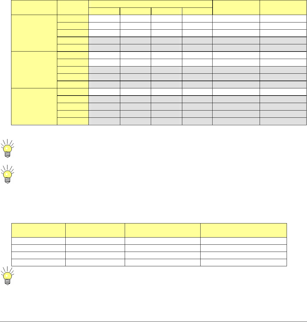
The following table gives the useful transmission bit rate for each COFDM mode. It also specifies the Carrier-to-Noise operation limit
in the case of a perfect line-of-sight (Gaussian) channel and in the case of a typical multipath terrestrial (Raylegh) channel.
Selection may be compromised due to the distance between the transmitter and receiver sites.
We can notice that a low code rate (= high data redundancy) is necessary to insure a good efficiency in
multipath environment.
The guard interval determines the maximum echoes length dispersion that the system can tolerate. From this figure, we can
estimate the maximum transmission range that the system might offer for a typical terrestrial channel (with adequate RF power).
The following table summarizes the results that come out from the 4 possible guard interval values:
Guard Interval
Ratio
Guard Interval
Duration (us)
Maximum echoes
dispersion (km)
Maximum transmission
distance (km)
1/32 7 2.1 2-6
1/16 14 4.2 4-12
1/8 28 8.4 8-24
1/4 56 16.8 16-48
Maximum transmission distances can be increased when using directive antennas, but signal break-ups
can nevertheless occur when long echoes occasionally enter the receiving antenna.
Useful Bitrate (Mb/s) Constellation
Scheme
Code
Rate GI=1/4 GI=1/8 GI=1/16 GI=1/32
C/N for perfect
channel (dB)
C/N for typical
channel (dB)
1/2 4,98 5,53 5,85 6,03 3.1 5.4
2/3 6,64 7,37 7,81 8,04 4.9 8.4
3/4 7,46 8,29 8,78 9,05 5.9 10.7
5/6 8,29 9,22 9,76 10,05 6.9 13.1
QPSK
7/8 8,71 9,68 10,25 10,56 7.7 16.3
1/2 9,95 11,06 11,71 12,06 8.8 11.2
2/3 13,27 14,75 15,61 16,09 11.1 14.2
3/4 14,93 16,59 17,56 17,10 12.5 16.7
5/6 16,59 18,43 19,52 20,11 13.5 19.3
16-QAM
7/8 17,42 19,35 20,49 21,11 13.9 22.8
1/2 14,93 16,59 17,56 18,10 14.4 16.0
2/3 19,91 22,12 23,42 24,13 16.5 19.3
3/4 22,39 24,88 26,35 27,14 18.0 21.7
5/6 24,88 27,65 29,27 30,16 19.3 25.3
64-QAM
7/8 26,13 29,03 30,74 31,67 20.1 27.9

6051412900 Rev - 27

6051412900 Rev - 28
ANNEX B: Tables and Packet Identifiers (PIDs)
The contents of the MPEG2 Transport stream are defined by ETSI EN 300 468, Digital Video Broadcasting (DVB); Specification for
Service Information (SI) in DVB Systems and ISO 13818-1. These documents define the information tables that describe the
organization of the transmitted data in addition to the video and audio content. These tables along with video, audio and private user
data are transmitted in packets. A Packet Identifier (PID) number is used to distinguish between packets. PIDs may have values
from 0 to 8191.
Not all the tables defined in the ETSI EN 300 468 are included in the CCII transmission. The ETSI EN 300 468 standards was
created for large network applications. There are a few standards that are not relevant to CCII applications. The tables transmitted
by the CCII are limited to those that enable the video and audio data to be found and decoded by a compliant decoder.
The CCII transmits the following Tables and information packets:
PAT (Program Association Table)
PMT (Program Map Table)
PCR (Program Clock Recovery) PID
Video PID
Audio PID
Private User Data PID
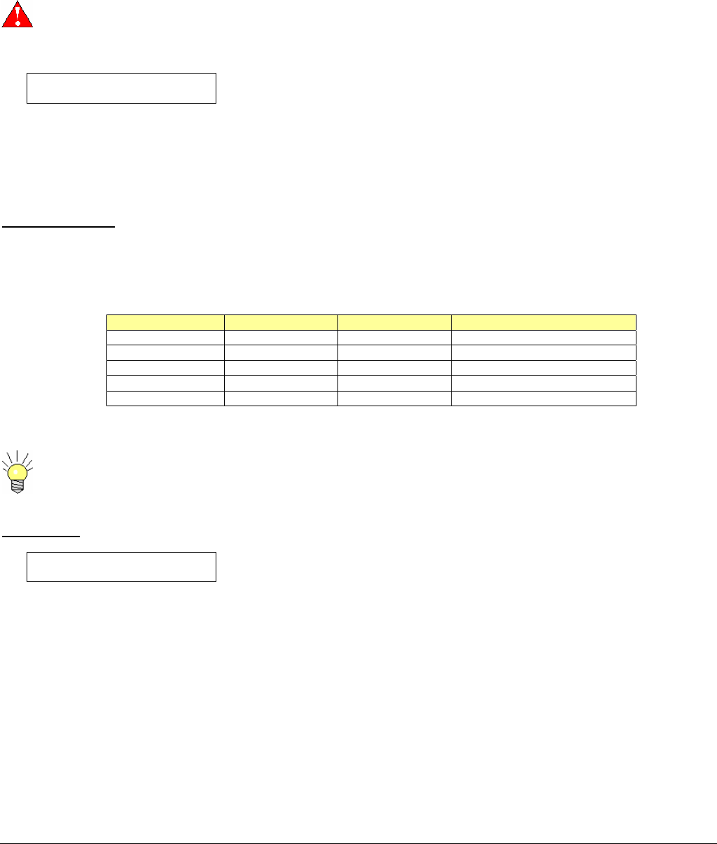
The default settings for the CCII are:
Table/PID Description BMS Systems
Default Value
PAT Program Association Table
Indicates which PID the PMT is to be found 000
PMT Program Map Table
Yields information about the Program, Video,
Audio and PCR PIDS.
200
Video PID Conveys Video Content 300
Audio PID Conveys Audio Content 301
PCR PID Conveys Program Clock Recovery Data 101
Private User Data PID Conveys the user data from the RS232 data
channel input 005

6051412900 Rev - 29
6051412900 Rev - Page 30
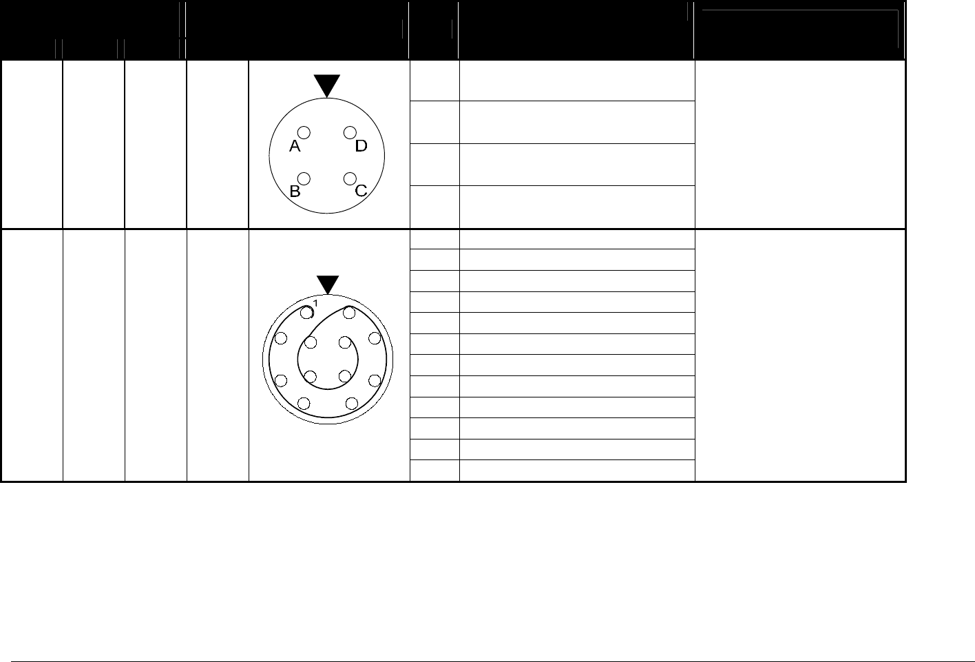
PIN OUT INFORMATION for 6GHz Carry-Coder II
System Frequency
2 GHz 4 GHz 6 GHz
Connector Pin
Mating Connector
Mating Cable
A +11 TO 32 VDC 2.6 A IN
B NC
C DC GROUND RETURN
J1
D NC
Connector PTO6E-8-4S(SR)
BMS p/n 210004900
For Custom Cable Use:
Belden 9740 or Equivalent
1 NC
2 GPS DATA IN
3 GROUND
4 GROUND
5 PC STATUS
6 PC COMMAND
7 GROUND
8 NC
9 NC
10 DOWNSTREAM STATUS
11 DOWNSTREAM COMMAND
J4
12 NC
Connector LEMO 12 PIN
BMS p/n 210051901
Cable BMS p/n
7314189040 (HCII)
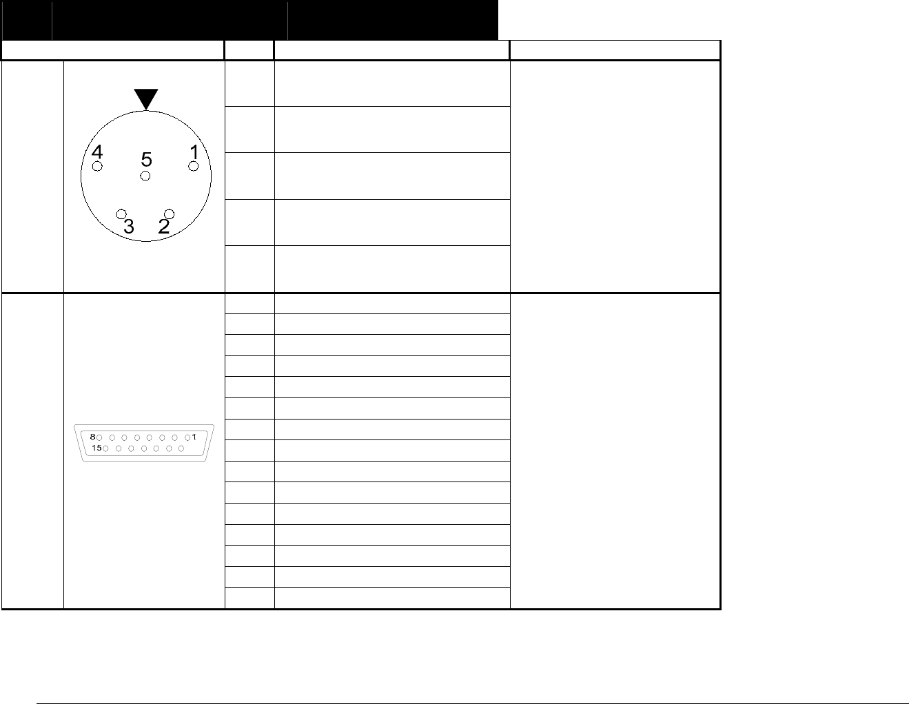
6051412900 Rev - Page 31
Pin Mating Connector
Mating Cable
1 AUDIO GROUND
2 LEFT AUDIO OUTPUT +
3 LEFT AUDIO OUTPUT -
4 RIGHT AUDIO OUTPUT +
J6
5 RIGHT AUDIO OUTPUT -
Connector TA5M Mini XLR
BMS p/n 210070951
Cable BMS p/n
7616201000 Camera Mount
7616201010 Back Pack
For Custom Cable Use:
Tefzel 4 Conductor 22 AWG
Shielded or Equivalent
1 NC
2 PC STATUS
3 PC COMMAND
4 NC
5 GROUND
6 RC BUSY
7 NC
8 RC SENSE
9 +5 VDC
10 NC
11 NC
12 NC
13 NC
14 NC
J10
15 NC
Connector DA-15P
BMS p/n 210052001
Cable BMS p/n
7314154000 CCII Remote
Broadcast Microwave Services, Inc. – 12367 Crosthwaite Circle – Poway, CA 92064 32
Phone: 800-669-9667, 1-858-391-3050 - Fax: 1-858-391-3049
Email: support@bms-inc.com Web: www.bms-inc.com
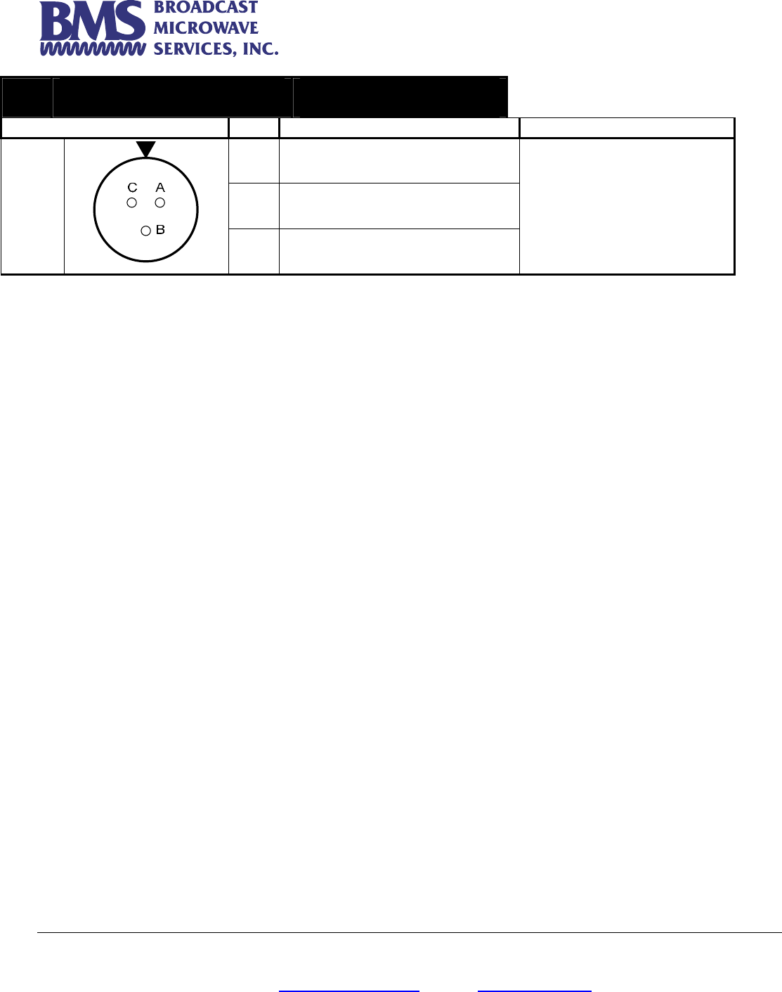
Pin Mating Connector
Mating Cable
A +Vp IN
B -Vp IN
J11
C CHASSIS GROUND
Connector PTO6E-8-3P
BMS p/n 210004601
Cable BMS p/n
7314189060 (HCII)