Broadcast Microwave Services FC-FCII-7 Field Coder II User Manual FCII Manual 4 FCC
Broadcast Microwave Services Inc Field Coder II FCII Manual 4 FCC
User manual
Installation and Operations Manual
Field-Coder II (FCII)
And Field-Coder II With Power Amplifier (FCII-MAX)
DOC# 6051420300 REV - February 2007
Broadcast Microwave Services, Inc.
12367 Crosthwaite Circle
Poway, CA 92064
800-669-9667, 858-391-3050
858-391-3049 FAX

INTRODUCTION
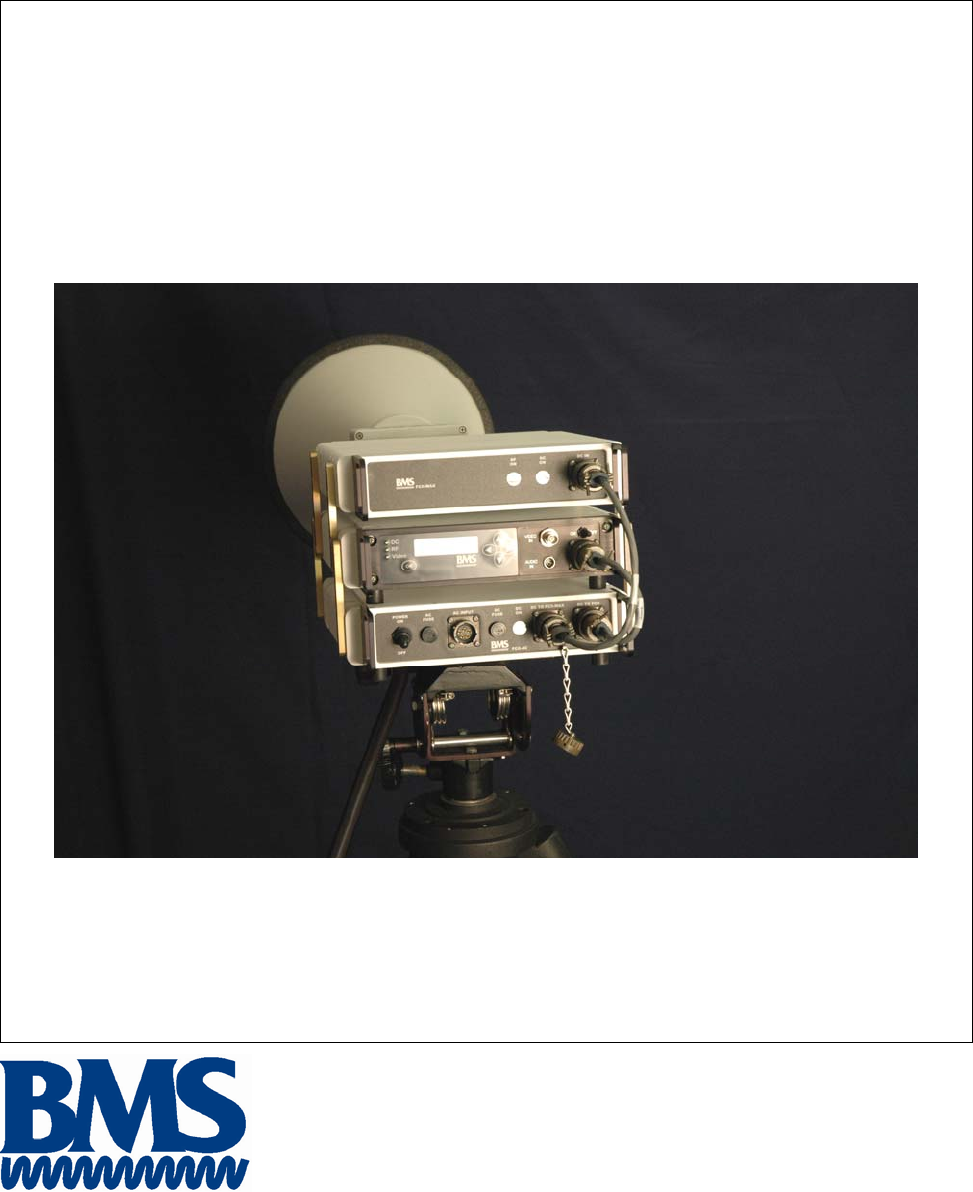
The Field-Coder II (FCII) microwave transmitter is portable COFDM transmitter designed for applications
that require temporary microwave link. Based on the field proven technology of the BMS Carry-Coder II,
the FCII is weather resistant, sturdy, robust, easy to set-up and simple to use. The FCII is a digital
transmitter and encoder compliant with COFDM DVB-T specifications. However The FCII by itself is
only a 1W transmitter, covering a short range. FCII-MAX, an external 5W PA is necessary to provide
enough range for the transmission. The FCII-MAX will operate by the FCII-AC, a powerful external power
supply. Similar to FCII-transmitter, both FCII-MAX and FCII-AC are weatherproof units.
Features:
• Digital Transmission
• 6 MHz Occupied Bandwidth Feature
• Simple Set-up and Operation
• 9 Presets
• Field-Proven Design
• Intuitive Operator Controls
• DVB-T Standard-Compliant
This document provides instructions for the installation, operation and maintenance of the Field-Coder II.
Broadcast Microwave Services (BMS) is a leader in wireless digital microwave technology providing
innovative products for the television broadcast, video, telemetry and surveillance industries. A wholly
owned subsidiary of Cohu, Inc., BMS designs and manufactures a comprehensive line of microwave
communications equipment for broadcasting sports venues, law enforcement and military applications.
BMS also builds and integrates command and control centers to provide fully functioning, complex, end to
end digital systems.
For the latest product and system information please visit www.bms-inc.com.
Broadcast Microwave Services, Inc.
12367 Crosthwaite Circle
Poway, CA 92064
Tel: +1 (858) 391-3050
Toll Free (US): 800-669-9667
Fax: +1 (858) 391-3049
Email:sales@bms-inc.com
Web: www.bms-inc.com

ii
This Page Intentionally Left Blank

iii
Table of Contents
INTRODUCTION........................................................................................................................................... i
SYSTEM DESCRIPTION ............................................................................................................................. 1
Configurations of the FCII......................................................................................................................... 1
FCII Family Components and Accessories................................................................................................ 2
Technical Specifications ............................................................................................................................ 3
FCII SET-UP with FCII-AC and FCII-MAX ........................................................................................... 7
Installing the Tripod Quick-Disconnect Mount to FCII-AC.................................................................. 7
Attaching the FCII, FCII-AC and FCII-MAX together......................................................................... 7
Cable Interconnections .......................................................................................................................... 9
USER INTERFACE..................................................................................................................................... 12
OPERATION ............................................................................................................................................... 18
Field Set-up.............................................................................................................................................. 18
For Tripod Use..................................................................................................................................... 18
Attaching the Horn Antenna................................................................................................................ 19
Cable Connections............................................................................................................................... 19
Operation.................................................................................................................................................. 20
Manually Configure FCII for Broadcast.............................................................................................. 20
Using a Preset Configuration............................................................................................................... 21
Shut Down ............................................................................................................................................... 21
PREVENTATIVE MAINTENANCE.......................................................................................................... 24
Maintenance Schedule ............................................................................................................................. 24
Suggested Spare Parts List ....................................................................................................................... 24
Fuse Replacement Procedure............................................................................................................... 24
WARRANTY............................................................................................................................................... 26
Additional References.............................................................................................................................. 28
US Broadcast Frequency Assignments................................................................................................ 29
Coded Orthogonal Frequency Division Multiplex (COFDM) Modulation ......................................... 30
GLOSSARY................................................................................................................................................. 34

i
List of Figures
Figure 1 FCII Architecture Block Diagram.................................................................................................... 1
Figure 2 FCII-AC, FCII, and FCII-MAX Bracket Attachment ...................................................................... 9
Figure 3 FCII-AC, FCII and FCII-MAX Attached Cable Connections ....................................................... 11
Figure 4 FCII Control Panel......................................................................................................................... 12
Figure 5 FCII Status Screen ......................................................................................................................... 12
Figure 6 Not Seated...................................................................................................................................... 18
Figure 7 FCII Seated in Tripod Mount......................................................................................................... 18
Figure 8 Close the Clamp ............................................................................................................................. 18
Figure 9 Fold the lever flush......................................................................................................................... 18
Figure 10 Not Locked................................................................................................................................... 19
Figure 11 Locked.......................................................................................................................................... 19
Figure 12 Align Antenna Mount with Bracket ............................................................................................. 19
Figure 13 Insert Antenna Mount into Bracket.............................................................................................. 19
Figure 14 Rotate Antenna to Lock ............................................................................................................... 19
Figure 15 Antenna Locked to Mount............................................................................................................ 19
Figure 16 Connect the RF Cable to the FCII................................................................................................ 20
Figure 17 Connect the RF Cable to the RF In Connector on the FCII-MAX............................................... 20
Figure 18 Replacing the AC Fuse................................................................................................................. 25
Figure 19 Replacing the DC Fuse................................................................................................................. 25
Figure 20 Product Label ............................................................................................................................... 26
List of Tables
Table 1 Physical Characteristics..................................................................................................................... 3
Table 2 RF Output.......................................................................................................................................... 3
Table 3 COFDM Parameters .......................................................................................................................... 4
Table 4 Video Inputs ...................................................................................................................................... 4
Table 5 Audio Input........................................................................................................................................ 5
Table 6 Normal Mode User Menus .............................................................................................................. 13
Table 7 Expert Mode User Menus................................................................................................................ 15

ii
WARNING!
RF RADIATION EXPOSURE HAZARD
This warning is provided by Broadcast Microwave Services (BMS) Inc. for safety purpose. The
following information help to reduce the risk of RF exposure hazard.
FCC Limit of RF Exposure
According to Federal Communication Commission (FCC), the Maximum Permissible Exposure (MPE) for
FR radiation has been set to 1.0 mW/cm2 for the Field-Coder II equipment (OET Bulletin 65).
The Field-Coder II with Power Amplifier is a non-broadcast transmitter and without an antenna it will not
create RF exposure (power density) exceeding the 1.0 W/cm2 FCC limit.
However a high-gain antenna such as a parabolic dish will greatly enhance the Field-Coder II output power
density beyond the MPE limit of 1.0 mW/cm2.
In this situation a minimum distance from the antenna needs to be calculated in order to keep the MPE
always below the safety limit. The calculation has been done for Field-Coder II based on the formula
mentioned in OET Bulletin 56.
The calculations have been done for different commonly used antenna in Electronic New Gathering (ENG)
systems.
Digital Transmission
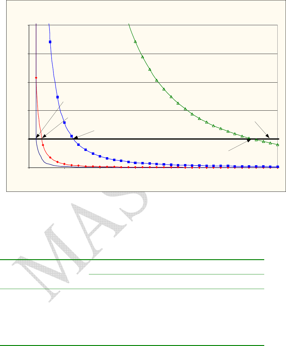
Figure 1 shows the plot of the minimum exposure distance for 0dBi, 5dBi, 16dBi, and 30dBi antennas. The
2 GHz Field-Coder II with Power Amp transmits the maximum power of 5 Watts. The minimum exposure
distances are found from the cross points of the exposure graphs (for various antennas) with the line of
maximum permissible exposure (i.e. 1 W/cm2). Notice that the numbers in Figure 1 predict the worse case
scenario, which is straight in front of the antenna (exposing to the antenna main-lobe). Obviously the side-
lobe exposures are well below these numbers as the radiation intensity dramatically reduces on the side
lobes.
iii
Estimated RF Exposure for 2 GHz Field-Coder II with 5W Power Amp
0.0
1.0
2.0
3.0
4.0
5.0
0 100 200 300 400 500 600 700
Distance, cm
Power Density, mW/cm^2
Max Permissible
Exposure: 1mW/cm2
30 dBi Antenna
Max Exposure at 560 cm
0 dBi Antenna
Max Exposure at 20 cm
16 dBi Antenna
Max Exposure at 120 cm
5 dBi Antenna
Max Exposure at 35 cm
Figure 1
Summary
In order the keep the RF exposure within the FCC limit, it is necessary to maintain the safe distance from
the antenna. The results shown in Figures 1 can be summarized in the following table:
Minimum permissible distance from antenna (cm)
Antenna Gain
(dBi)
0 25
5 40
16 130
30 620
Notice the above table indicates worst-case situation (straight in front of the antenna).
1
SYSTEM DESCRIPTION
The Field-Coder II system is a portable 1W digital transmitter for wireless transmission of video, audio,
and user defined private data. Built on the same platform as the field proven Carry-Coder II, the FCII has
many of the same features and capabilities.
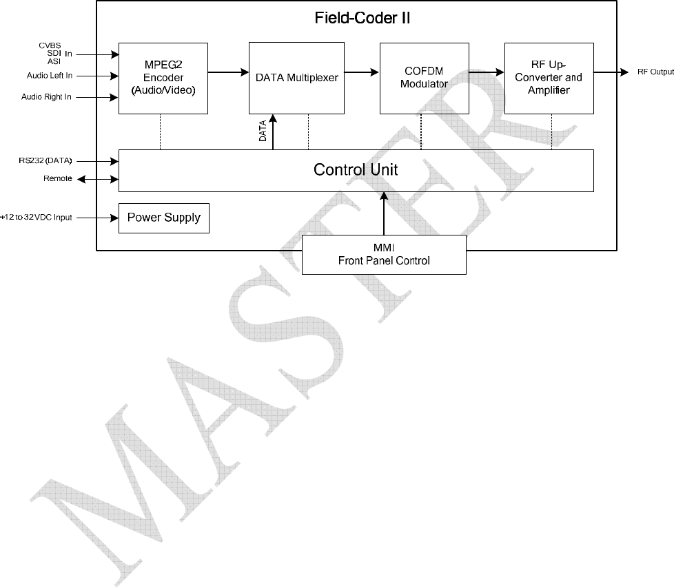
Figure 1 FCII Architecture Block Diagram
The FCII supports 2 audio (analog) inputs and one video (CVBS, SDI or ASI) input. The FCII includes an
MPEG2 encoder and a DVB-T compliant COFDM modulator. Both MPEG and COFDM parameters are
fully configurable by the system controller in support of optimum performance and compatibility with
other equipment. For those users less familiar with detailed COFDM and MPEG settings, there are 3 preset
robustness settings (low, mid and high) that each optimize video performance at the expense of modulation
complexity. High robustness provides the lowest quality video but is able to operate in severely
compromised locations. Low robustness provides the best quality video but may require a clear line of sight
shot.
An auxiliary data channel is provided that can be configured to transmit data (GPS, etc.) at baud rates up to
9600 bps.
The FCII can be controlled directly through the Front Panel or remotely.
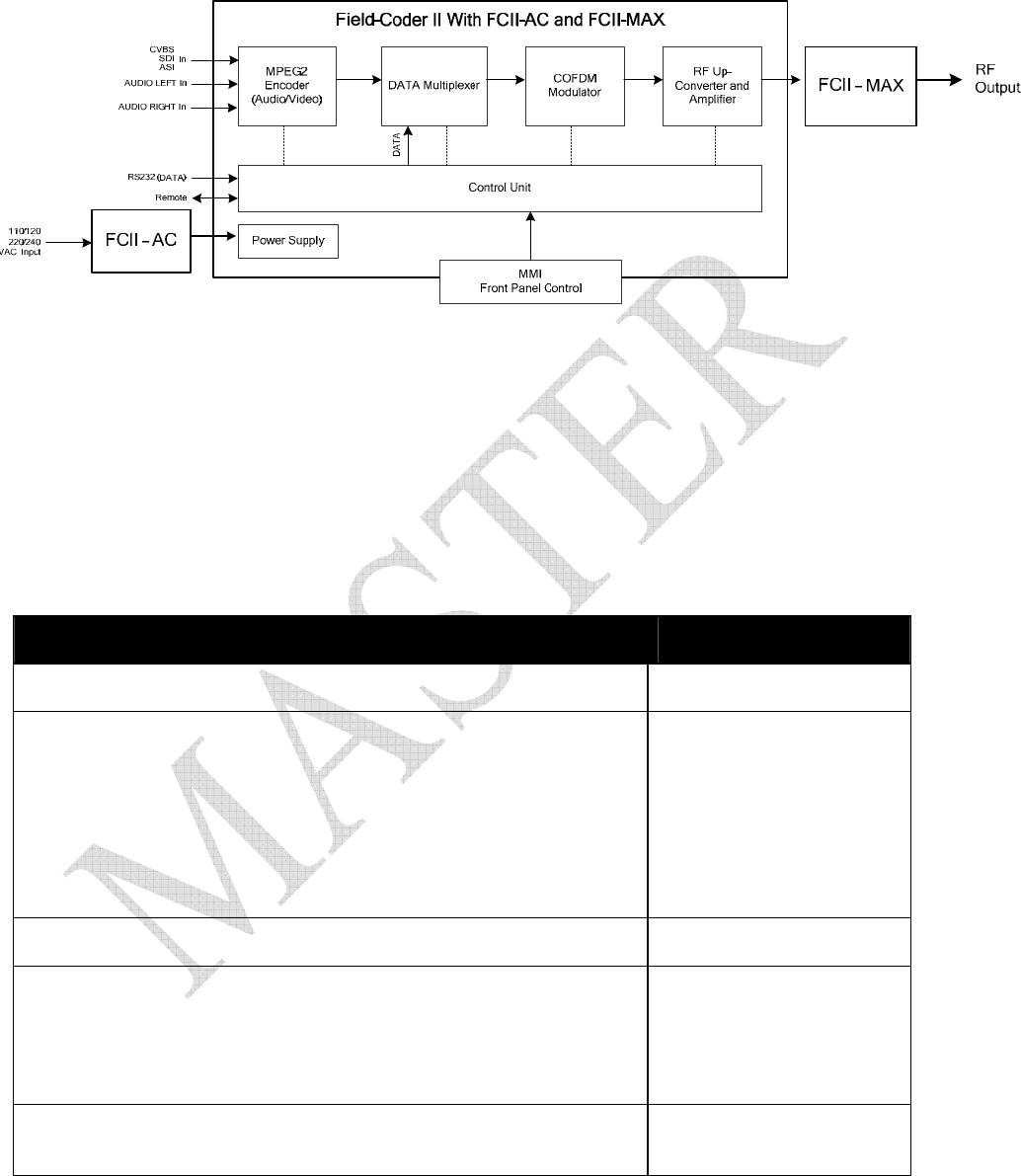
Configurations of the FCII
The FCII can be used:
• Independently – when supplied with +12 to + 32 VDC
• With the FCII-AC (AC to DC Power Converter) – to power the FCII from AC source
• With Both the FCII-MAX and FCII-AC – FCII-AC powers both the FCII and FCII-MAX
2
The FCII-AC is a weatherproof AC/DC power supply that can be used to power both the FCII and the
FCII-Max from 110/220 VAC.
As a stand alone unit, the FCII is a 1 W digital transmitter. The FCII – MAX will increase the power
output to 5W, significantly increasing the transmission range and robustness. Conveniently, the FCII-
MAX can also be powered by the FCII-AC.
FCII Family Components and Accessories
The FCII Family consists of the following components and accessories:
Component BMS Part Number
FCII 8014203XXX
FCII Accessory Kit
Audio Cables,
DC Power Cord,
System DC Power Cord
Tripod Bracket Assy
FCII Side Brackets (4)
10-32 x 3/8 FH Screws (20)
Installation and Operation Manual
7614203020
7314203000
7313444060
7314204009
7614203040
4414203001
281006800
6051420300
FCII – MAX 8014205XXX
FCII – MAX Accessory Kit
N to N RG213 Cable
System DC Power Cord
FCII Side Brackets (4)
10-32 x 3/8 FH Screws (20)
7614205000
7310111009
7314204012
4414203001
281006800
FCII – AC
AC Power Cord
8014204000
7313444040

3
Accessory Components BMS Part Number
BTA-100 Tripod w/ Quick Disconnect head (optional) 8001285903
Mount for Tripod use (included with FCII Accessory Kit)
(used on FCII or FCII-AC for Tripod w/ Quick Disconnect head)
3/8 - 16 x 5/8” FH Screw
¼ - 20 x 5/8” FH Screw
Mounting Plate
7614203040
290133858
281007105
4414203051
Tripod Transit Case (optional) 250000050
Antenna Options BMS Part Number
Horn Antenna (16 dBi Vertical Horn)
w/Field-Lock Bracket (quick-disconnect)
8014203005
Horn Antenna (16 dBi RHC)
w/Field-Lock Bracket (quick-disconnect)
8014203015
Field-Lock Bracket Mount
(used on FCII or FCII-MAX, required to use Horn Antenna quick-disconnect)
1/4-20 X 1" SH Cap Screw SS
1/4" .78" THK High Collar S/L Washer SS
7614203010
290191410
290301400
Field-Lock Bracket
(required to convert existing Horn Antenna to quick disconnect mount)
7614203000
Technical Specifications
Table 1 Physical Characteristics
FCII FCII – MAX FCII – AC
Size 10.5”W x 11.25”D x 2.15” H ~ 9” W x 11” D x 2.5” H 9” W x 11” D x 2.5” H
Weight ~ 9.5 lbs. ~ 9.5 lbs. ~ 9.5 lbs.
Voltage Required +11 to +32 VDC +11 to +32 VDC 90-240 VAC
Power 56 Watts Max.
with 1 Watt RF Output
95 Watts Max.
with 4 Watts RF Output 150 Watts @ 28 VDC
Fuse
N/A N/A
AC – 4A Fuse
BMS p/n 514000404
DC – 6.3A Fuse
BMS p/n 514000463
Temperature
Range -20 to +65 °C -20 to +65 °C -20 to +65 °C
Relative Humidity Up to 98% NC Up to 98% NC Up to 98% NC
Altitude 15,000’ ASL 15,000’ ASL 15,000’ ASL
Table 2 RF Output
S-Band
Frequency Range 1990 MHz - 2.5 GHz

4
Frequency Step 250 kHz
Channel Plan Programmable
Modulation COFDM (2K carriers)
Output Power 50 mW, 100 mW, 250 mW and 1W (selectable)
Shoulders at +/- 4.2 MHz > 30 dB for 1W
> 35 dB for 250 mW or less
Harmonic and Spurious < -60 dBc (DC to 6 GHz)
Return Loss 18 dB (typical)
Table 3 COFDM Parameters
COFDM Parameter Specification
Guard Interval of Symbol 1/4 , 1/8, 1/16 or 1/32
Modulation of Sub-Carriers QPSK, 16QAM, 64QAM
Error Correction Viterbi (code rate : 1/2, 2/3, 3/4, 5/6 or 7/8)
Reed-Solomon (204, 188)
Channel Bandwidth 8/7/6 MHz
Standard ETS 300 744 (DVB-T)
Table 4 Video Inputs
Video Input Parameter Specification
Video Input CVBS
Composite Video
Baseband Signal
SDI
Serial Digital Interface
ASI
Asynchronous Serial
Interface
Encoding Standard MPEG2
ISO/IEC 13818-2
SMPTE 259M
CCIR601
DVB-ASI
TR 101 891
Format
PAL 625 lines / 50 Hz / Fsc = 4.43 MHz
NTSC 525 lines / 60 Hz / Fsc = 3.58 MHz
Impedance 75 Ohms
Connector BNC - Female

5
Table 5 Audio Input
Audio Input Parameter Specification
Audio Input Analog (Line – Symmetrical)
Channels 2 separate channels (Left and Right)
Nominal Level Adjustable from –9 dBu to +4 dBu (0 dBu = 775 mV)
Headroom 12 dB (analog) – 18 dBFs (digital)
Sampling Frequency 48 kHz – 20 bits
Frequency Response 30 Hz – 20 kHz (+/- 0.5 dB)
Signal-To-Noise Ratio 75 dB
Total Harmonic Distortion < 0.5 % @ 1kHz
Impedance < 100 Ohms

6
This Page Intentionally Left Blank
7
FCII SET-UP with FCII-AC and FCII-MAX
The FCII can also be used with the FCII-AC and the FCII-MAX together. Using the brackets (BMS p/n
4414203001) to join the three components, and installing the quick disconnect tripod mounting plate to the
bottom of the FCII-AC will speed up field set-up. The FCII-AC should be placed on the bottom of the
stack, with the FCII in the middle and the FCII-MAX on the top. The preparation for quick field set-up is
as follows:
• Tripod Quick Disconnect Mound Installation to the FCII-AC (if applicable)
• Installing Antenna bracket quick disconnect Mount to the FCII-MAX
• Attaching the FCII, FCII-AC and the FCII-MAX together
• Cable Interconnections
Installing the Tripod Quick-Disconnect Mount to FCII-AC
Please follow the procedures in section Error! Reference source not found. Error! Reference source not
found. to install the tripod quick disconnect mounting plate to the FCII-AC.
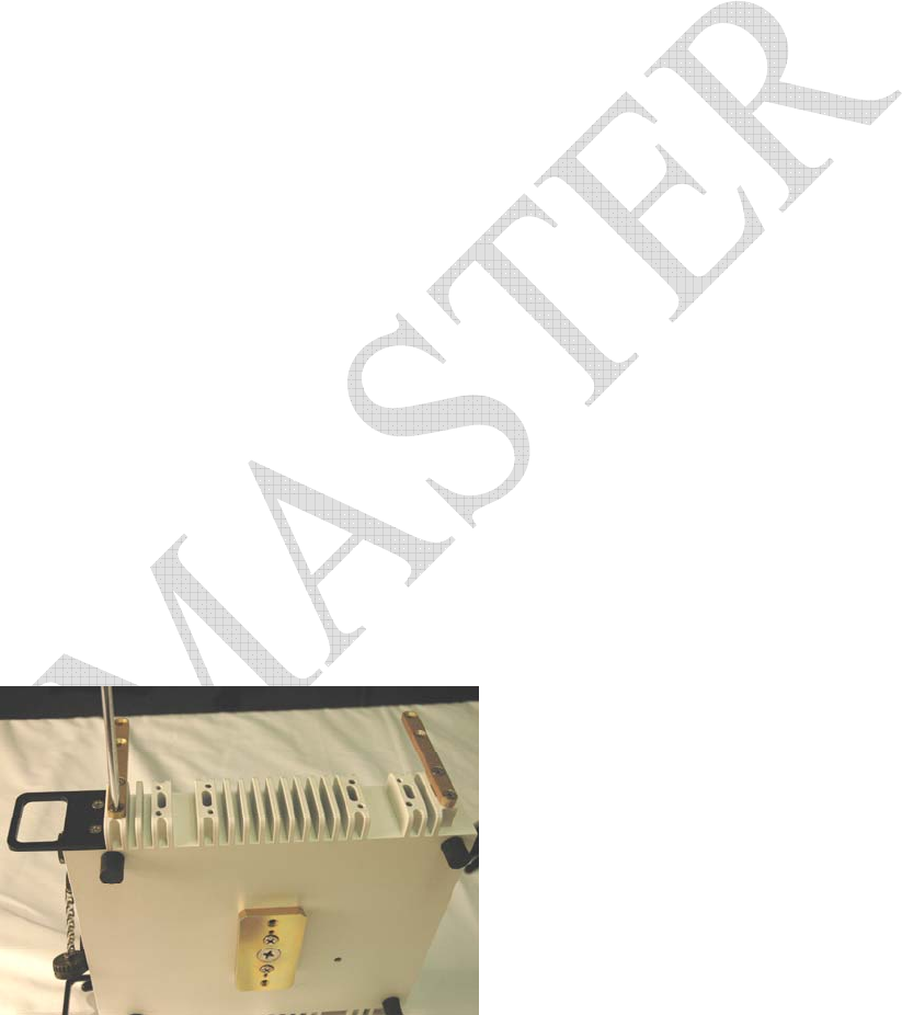
Attaching the FCII, FCII-AC and FCII-MAX together
When using the FCII with the FCII-AC and the FCII-MAX it is convenient to stack them all together. The
stack order is as follows; FCII-AC on the bottom, FCII in the middle, and the FCII-MAX on top. This
allows for proper access and adequate cooling for each component.
The FCII components are designed to be stacked on top of each other and secured by simple brackets on
either side. There are 6 sets of threaded holes, 3 pair forward, 3 pair toward the back, on either side of the
components. There is no real requirement for which sets are used provided the load is distributed both
front and back and the components are stacked flush with each other.
Tools Needed:
#2 Phillips Head screwdriver
The design of the FCII-AC requires that it is placed on the bottom of the stack. Use 4 #10-32 screws to
secure, but do not tighten, two brackets, one forward, one back to one side of the FCII-AC.
Use 4 #10-32 screws to secure, but do not tighten, the two brackets on the opposite side of the FCII-AC.
Align the FCII so that it is facing the same way as the FCII-AC.
8
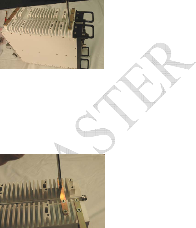
Slip the FCII in between the brackets.
Secure the FCII to the brackets using the matching hole set used on the FCII-AC. The FCII should be
stacked directly on top of the FCII-AC, not staggered.
Tighten all screws.
The FCII-MAX power amplifier requires proper heat transfer. The FCII-MAX needs to be on the top of
the stack.
Use 4 #10-32 screws to secure, but do not tighten, two brackets, one forward, one back to one side of the
FCII.
Use 4 #10-32 screws to secure, but do not tighten, the two brackets on the opposite side of the FCII.
Align the FCII-MAX so that it is facing the same way as the FCII-AC and FCII.
Slip the FCII-MAX in between the brackets.
Secure the FCII-MAX to the brackets using the matching hole set used on the FCII. The FCII-MAX
should be stacked directly on top of the FCII, not staggered.
Tighten all screws.
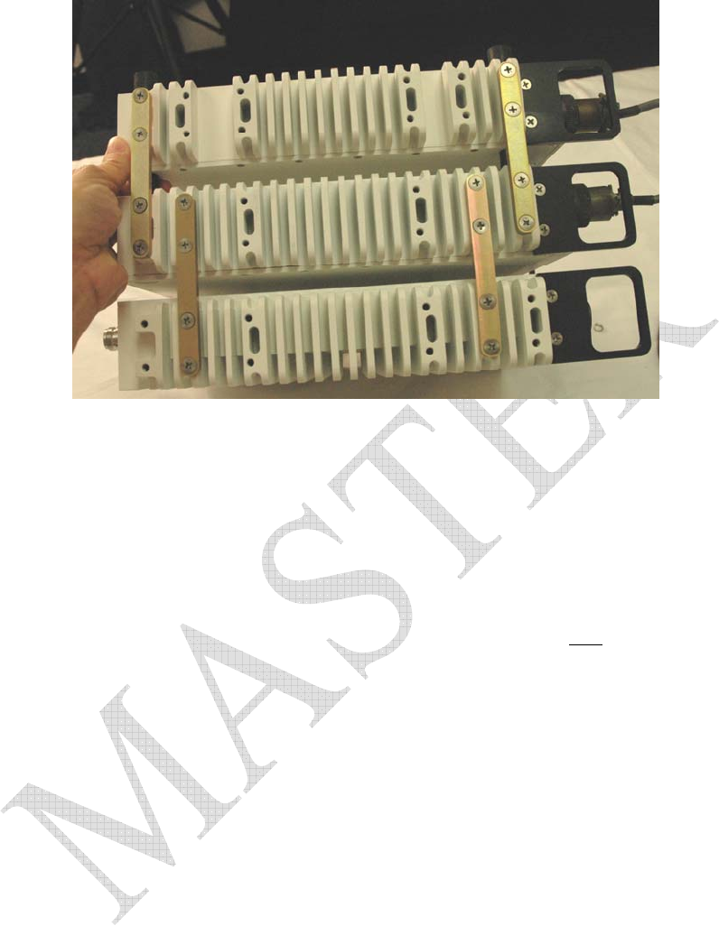
Figure 2 is an example of one way to install the brackets used to attach the FCII-AC, FCII and FCII-MAX
together.
9
Figure 2 FCII-AC, FCII, and FCII-MAX Bracket Attachment
Cable Interconnections
To hasten field set-up time, it is advantageous to have some of the interconnect cables already connected.
The cable connections between the three components are as follows:
The power cable from the FCII-AC to the FCII
The power cable from the FCII-AC to the FCII-MAX
The RF cable from the FCII to the FCII-MAX, this cable is connected in the field after the Horn Antenna is
mounted.
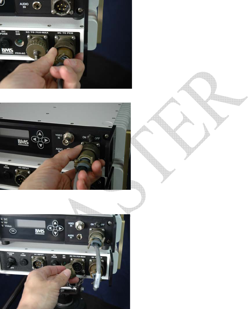
The power connection DC to FCII on the FCII-AC to the power input connector on the FCII located right
below the ON OFF switch.
To connect the power connection from the FCII-AC to the FCII, align the connector, matching the keys on
one side to the grooves on the other.
10
Slide the connector into place and twist connector housing to secure.
Repeat for connecting the cable to the FCII.
To connect the power cable from the FCII-AC to the FCII-MAX, remove the attached connector cover.
Align the proper connector on cable BMS p/n 7314204012 , matching the keys on one side to the grooves
on the other.
Push the connector in place and twist the connector housing to lock the connector down.
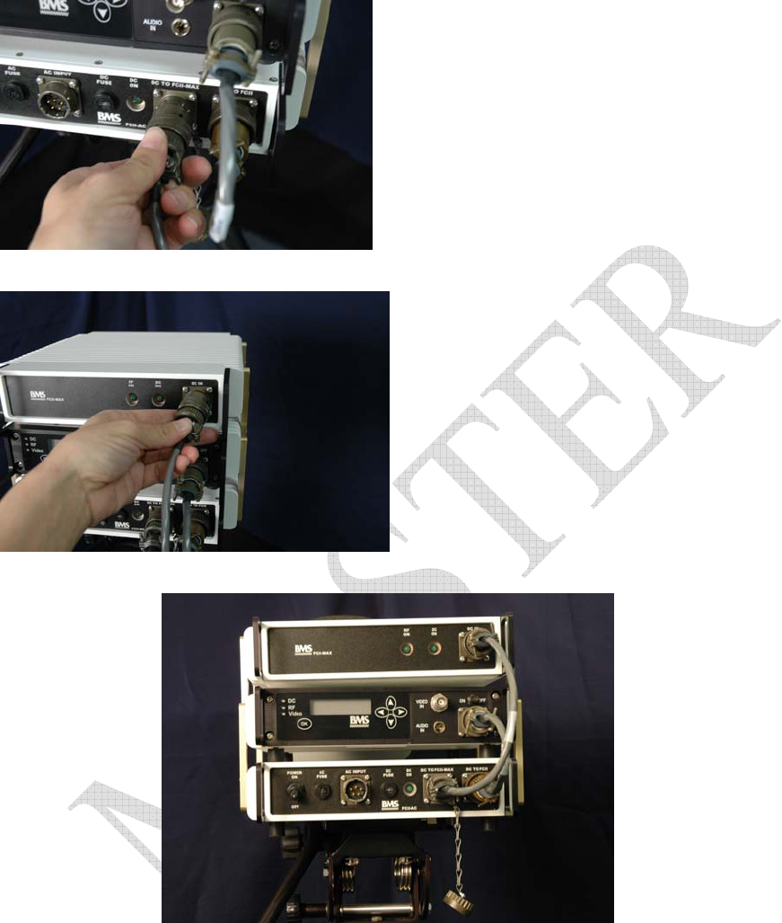
11
Repeat with connecting the other end of the cable to the FCII-MAX.
Figure 3 demonstrates how the cables should look when all three components are attached.
Figure 3 FCII-AC, FCII and FCII-MAX Attached Cable Connections
This completes the FCII preparation for quick field set-up for this configuration. Please proceed to
Sections 0 and Error! Reference source not found. to continue with the initial set-up for the FCII.
USER INTERFACE
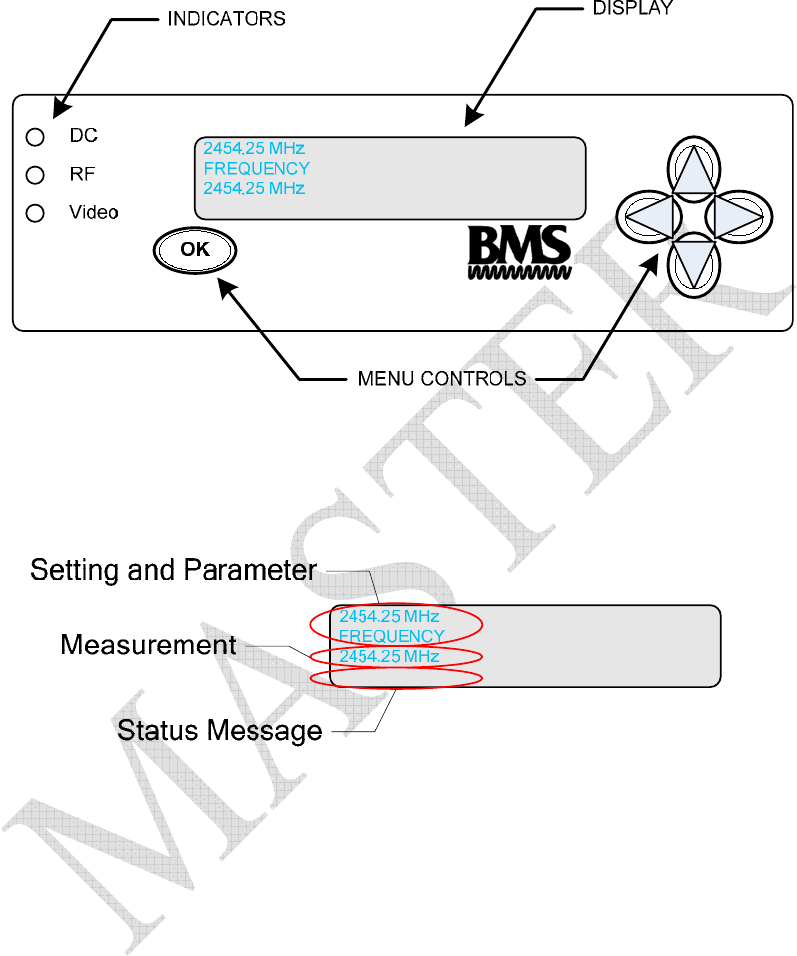
All the transmission parameters are configured through the control panel.
Figure 4 FCII Control Panel
Figure 5 FCII Status Screen
Pressing any of the menu controls will bring up the menu screens. Use the Ï and Ð buttons to scroll through the
menus. Pressing OK on a menu screen will allow changes to that menu’s parameters. The Î and Í buttons move
the cursor. The FCII display will return to the status screen after 30 seconds of no-input, or when the Ï and Ð buttons
are pressed simultaneously.
The FCII has two tiers of menus, Normal and Expert. The Normal menus provide control of system functions that are
needed in routine portable transmission situations. The Normal menus are the more frequently used menus. The
Expert Menus are used for advanced configuration of the FCII. The Expert menus enable the operator to selectively
adjust key (audio and video) compression and COFDM transmission parameters. The Expert menus should be reserved
to advanced users. Improper configuration of the Expert menu parameter settings could result in transmission failure.
13
What follows is a list of all the FCII menus, with brief description and instructions for use.
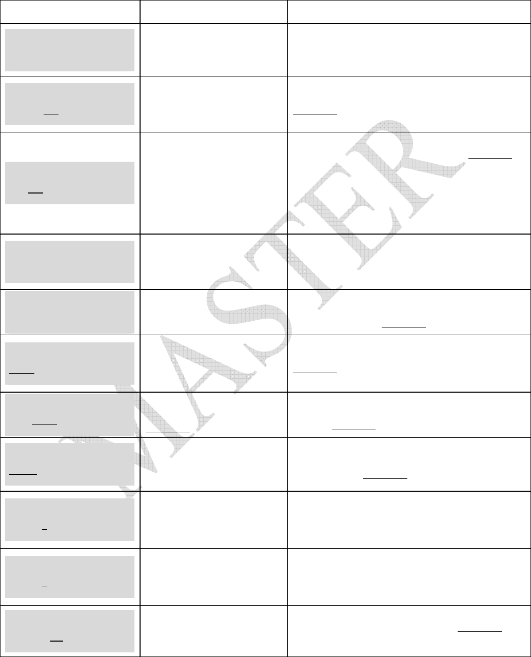
Table 6 Normal Mode User Menus
Normal Menu Description How to Use
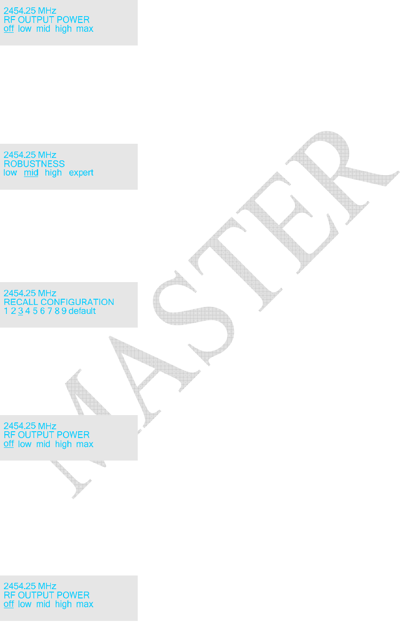
2454.25 MHz
FREQUENCY
2454.25 MHz
RF Frequency
Displays RF Transmit
Frequency.
To set the RF Frequency press OK. Use the Ï and Ð
buttons to change the value. The Î and Í buttons
move the cursor. Press OK when finished.
2454.25 MHz
RF OUTPUT POWER
off low mid high max
RF Output Power
Boost or Reduce Signal Strength
To set the RF Output Power, press OK. Use the Î and
Í buttons to navigate choices. The current choice is
underlined. Press OK to when finished.
2454.25 MHz
ROBUSTNESS
low mid high expert
Transmission Robustness
Choose from 3 predefined
settings, or operate in Expert
Mode
Change the Robustness by using the Î and Í buttons
to navigate choices. The current choice is underlined.
Press OK to set.
Low – Studio,
Mid – News, Sports, Entertainment
High – Mobile/Airborne
Expert – Custom Configuration
2454.25 MHz
RECALL CONFIGURATION
1 2 3 4 5 6 7 8 9 default
Recall Configuration Recall a saved configuration. Press OK to change. Use
the Ï and Ð buttons to change the value. The Î and
Í buttons move the cursor. Press OK when finished.
Default is set by the factory
2454.25 MHz
SAVE CONFIGURATION
1 2 3 4 5 6 7 8 9
Save Configuration
Allows a set of parameters to be
recalled at a later time.
To save a configuration after all parameters have been
set, use the Î and Í buttons to select where to save.
The current choice is underlined. Press OK to save.
2454.25 MHz
VIDEO INPUT
CVBS YUV SDI ASI
Video Input Mode
YUV is not an option for the
FCII. The FCII will default to
CVBS
To change the Video Input Mode,, use the Î and Í
buttons to navigate choices. The current choice is
underlined. Press OK to set.
2454.25 MHz
VIDEO MODE
PAL NTSC
Video Mode
Current Video Mode is
underlined
Change the Video Mode from PAL to NTSC. Use the
Î and Í buttons to navigate choices. The current
choice is underlined. Press OK to set.
2454.25 MHz
AUDIO INPUT
analog SDI
Audio Input Change the Audio Input from analog to SDI.
Use the Î and Í buttons to navigate choices. The
current choice is underlined. Press OK to set.
2454.25 MHz
AUDIO LEVEL LEFT
-9--------0+++4
Audio Output Level Left
Channel
Displays Audio Output level for
the left channel
Set the Audio Output Level. Use e the Î and Í
buttons to move the cursor. Press OK when finished.
2454.25 MHz
AUDIO LEVEL RIGHT
-9--------0++++4
Audio Output Level Right
Channel
Displays Audio Output level for
the right channel
Set the Audio Output Level. Use e the Î and Í
buttons to move the cursor. Press OK when finished.
2454.25 MHz
DATA PORT BAUD RATE
1.2 4.8 9.6
Auxiliary Data Rate
Configure the Aux. RS232 Port
Baud Rate
To change the baud rate, use the Î and Í buttons to
navigate choices. The current choice is underlined.
Press OK to set.

14
Normal Menu Description How to Use
2454.25 MHz
DATA PORT MODE
CCII CCI
Auxiliary Data Port Mode
Configure the Aux. RS232 Port
To change the data port mode, use the Î and Í
buttons to navigate choices. The current choice is
underlined. Press OK to set.
2454.25 MHz
Scrambling
off enter PIN
Scrambler Privacy Identification
Number
Enable transmission privacy
scrambling. Current selection is
in underlined
To set the Privacy Identification Number for
transmission privacy, use the Î button to select “enter
PIN”. Press OK. Use the Ï and Ð buttons to change
the value. The Î and Í buttons move the cursor.
Press OK when finished.
Note that the PIN only shows when it is being set. This
PIN must match the reciever PIN. When operating with
a DCI, the first two digits must be set to zero and rest
must be from0 to 9. <00####>
2454.25 MHz
Channelized System
OFF ON
Use Channelized Frequencies Use the Î and Í buttons to navigate choices. The
current choice is underlined. Press OK to set.
2454.25 MHz
USER MODE
normal expert
User Mode
Allows access to EXPERT Level
Menus
Normal mode provides operation simplicity for routine
use. Expert mode allows the user to selectively adjust
key compression and COFDM settings. Specific
parameters are required to ensure proper operation. For
this reason, EXPERT mode is reserved for trained
“Expert” users.
Use the Î and Í buttons to navigate choices. The
current choice is underlined. Press OK to set.

NOTE:
The Expert Menus should only be configured by advanced users. Improper configuration can result in transmission
failure.
Table 7 Expert Mode User Menus
Expert Menu Description How to Use
2454.25 MHz
Video bitrate
4.35 Mbps
Video Bitrate
Controls Picture Resolution.
Larger values increase the
resolution and increases the time
between picture updates. Smaller
values decrease resolution and
decreases the time between picture
updates.
This is an EXPERT Level parameter
To change the video bitrate, press OK. Use the Ï and
Ð buttons to change the value. The Î and Í buttons
move the cursor. Press OK when finished.
2454.25 MHz
GOP STRUCTURE
I IP IBP IBBP 422IBBP
GOP Structure
Controls the structure of picture
groups. Affects video encoding
delay
This is an EXPERT Level parameter
To set the GOP structure, use the Î and Í buttons to
navigate choices. The current choice is underlined.
Press OK to when finished.
2454.25 MHz
GOP LENGTH
6 12 18 24
GOP Length
Set the length of picture groups.
High value, longer group, better
quality, more chance for errors.
This is an EXPERT Level parameter
To set the GOP length, use the Î and Í buttons to
navigate choices. The current choice is underlined.
Press OK to when finished.
2454.25 MHz
CONSTELLATION
QPSK 16QAM 64QAM
Constellation
Individually modulates each sub-
carrier of the COFDM signal.
QPSK most robust, low data rate,
64QAM least robust, fastest data
rate
This is an EXPERT Level parameter
To set the constellation, use the Î and Í buttons to
navigate choices. The current choice is underlined.
Press OK to when finished.
2454.25 MHz
GUARD INTERVAL
1/32 1/16 1/8 1/4
Guard Interval
Guards both ends of a symbol.
Higher ratios more robust than
lower ratios
This is an EXPERT Level parameter
To set the Guard Interval use the Î and Í buttons to
navigate choices. The current choice is underlined.
Press OK to when finished.
2454.25 MHz
CODE RATE
1/2 2/3 3/4 5/6 7/8
Code Rate
Ratio of signal to error correction.
Higher values, faster rate, but more
errors the slower, lower ratios.
This is an EXPERT Level parameter
To set the coder rate, use the Î and Í buttons to
navigate choices. The current choice is underlined.
Press OK to when finished.
2454.25 MHz
Channel Bandwidth
8 7 6 MHz
Channel Bandwidth
This is an EXPERT Level parameter
To set the Channel Bandwidth, use the Î and Í
buttons to navigate choices. The current choice is
underlined. Press OK to when finished.
2454.25 MHz
Serial Address
0123456789ABCDEF
Serial Address
Set to 6 in all cases except when
the CCII is being controlled by
something other than the Remote.
This is an EXPERT Level parameter
Set the Serial Address, use the Î and Í buttons to
navigate choices. The current choice is underlined.
Press OK when finished.

16
Expert Menu Description How to Use
2454.25 MHz
Scrambling Type
A B
Scrambler Type
Type A – Most Common
Type B – Rare
This is an EXPERT Level parameter
To set the Scrambler Type, use the Î and Í buttons
to navigate choices. The current choice is underlined.
Press OK to when finished.
2454.25 MHz
Video PID
300
Video Packet Identifier
BMS default is 0300
This is an EXPERT Level parameter
To set the Video PID, press OK. Use the Ï and Ð
buttons to change the value. The Î and Í buttons
move the cursor. Press OK when finished.
2454.25 MHz
Audio PID
301
Audio Packet Identifier
BMS default is 0301
This is an EXPERT Level parameter
To set the Audio PID, press OK. Use the Ï and Ð
buttons to change the value. The Î and Í buttons
move the cursor. Press OK when finished.
2454.25 MHz
PCR PID
101
Program Clock Recovery
BMS default is 0101
This is an EXPERT Level parameter
To set the PCR PID, press OK. Use the Ï and Ð
buttons to change the value. The Î and Í buttons
move the cursor. Press OK when finished.
2454.25 MHz
PMT PID
200
Program Map Table
BMS default is 0200
This is an EXPERT Level parameter
To set the PMT PID press OK. Use the Ï and Ð
buttons to change the value. The Î and Í buttons
move the cursor. Press OK when finished.
2454.25 MHz
SDT String
BMS Camera 01
Stream Description Table String
Provides a unique identifier to a
transmission stream. When using
ASI, the FCII will employ the SDT
String specified with the ASI
Signal.
This is an EXPERT Level parameter
To set the SDT, press OK. Use the Ï and Ð buttons
to change the value. The Î and Í buttons move the
cursor. Press OK when finished.

This Page Intentionally Left Blank
18
OPERATION
Field Set-up
These instructions are for setting up FCII systems that have been prepared and configured for quick field
set-up. If the FCII system is not being used with a tripod, be sure to set the FCII on a stable surface before
installing the antenna, connecting power, or operating.
For Tripod Use
Set the tripod up so that it is stable.
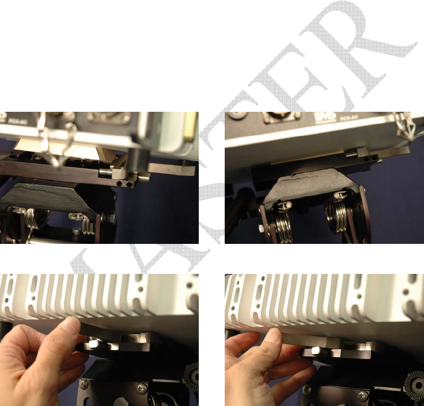
Mounting on the Tripod
Seat the FCII Tripod Mounting Plate into the Tripod Mount. Fully extend the lever and angle the unit to
maneuver the mounting plate in on one side, then the other. When it is seated, the mounting plate will be
just barely visible.
Figure 6 Not Seated
Figure 7 FCII Seated in Tripod Mount
Figure 8 Close the Clamp
Figure 9 Fold the lever flush
Lock the Clamp.
19
Figure 10 Not Locked
Figure 11 Locked
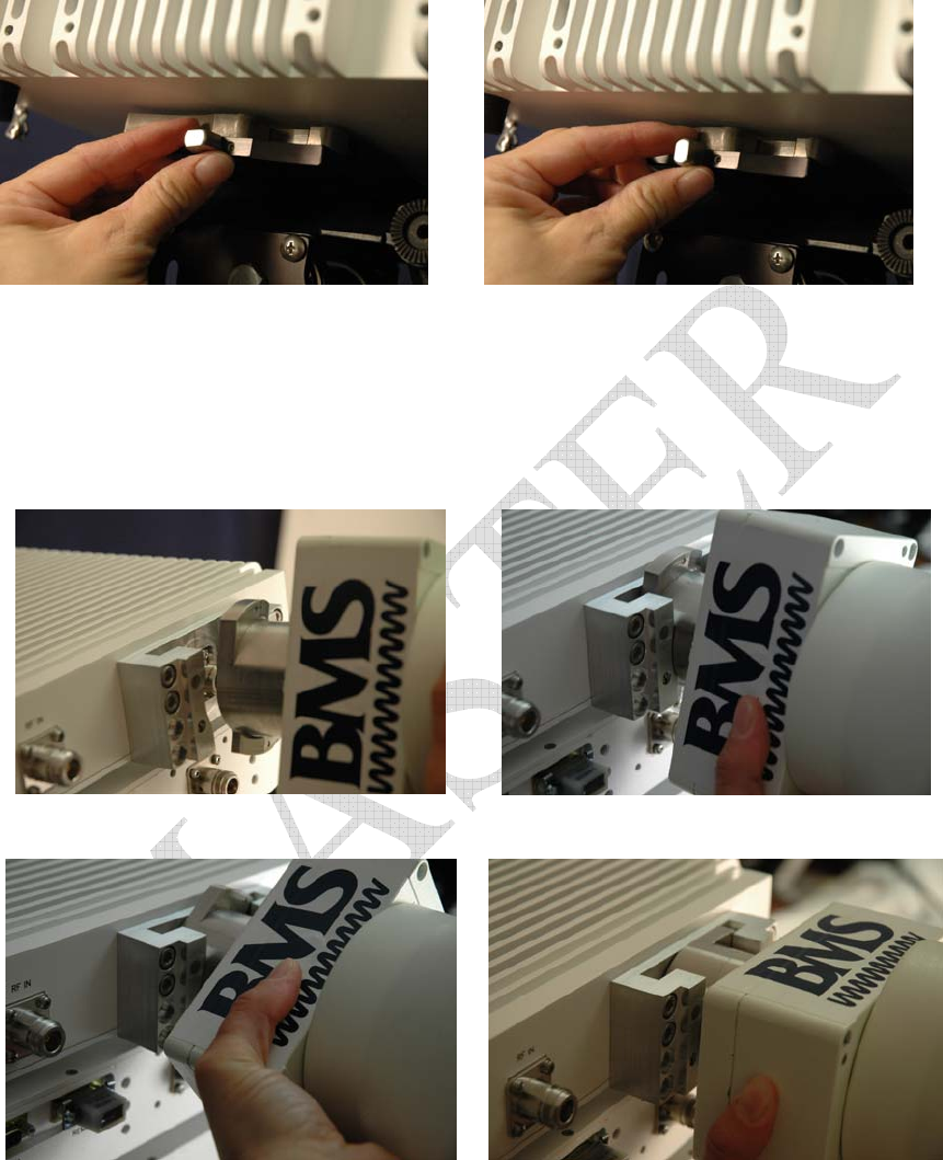
Attaching the Horn Antenna
Align the antenna bracket on the horn antenna perpendicular to the bracket mount on the back of the FCII
or FCII-MAX unit.
Figure 12 Align Antenna Mount with Bracket
Figure 13 Insert Antenna Mount into Bracket
Figure 14 Rotate Antenna to Lock
Figure 15 Antenna Locked to Mount
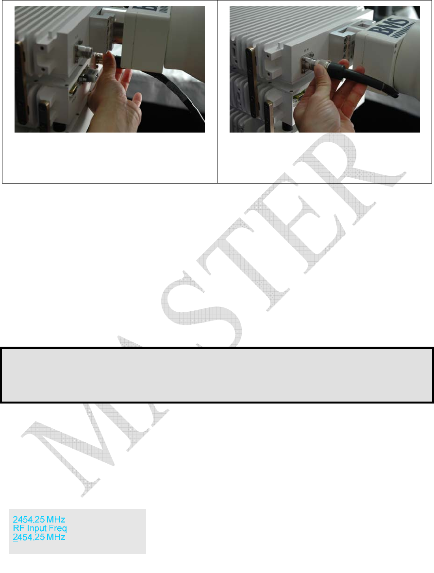
Cable Connections
If using the FCII-MAX, connect the RF cable from the FCII to the RF In connection on the FCII-MAX
after installing the Horn Antenna.
20
Figure 16 Connect the RF Cable to the FCII
Turn the knurled sleeve to tighten
Figure 17 Connect the RF Cable to the RF In
Connector on the FCII-MAX
Turn the knurled sleeve to tighten
Connect the video input to the VIDEO IN connector on the FCII front panel.
Connect the audio input to the AUDIO IN connector on the FCII front panel.
Supply the FCII with power either 28VDC direct to the FCII via the terminal under the ON/OFF switch, or
AC (120 or 240) through the FCII-AC via the AC-INPUT connector on the front panel.
Operation
Verify all cable connections are secure.
Turn video source on. FCII will not transmit without a valid video source.
Turn on the FCII-AC power (if applicable).
Turn on the FCII.
Note:
The FCII stores the operating settings upon shut down. When it is restarted, the FCII starts in the same
state it was shut down in. If the FCII was shut down during transmission, it will start in transmission, with
the same settings it had when it was last operated.
Manually Configure FCII for Broadcast
Select Frequency
Press the any of the menu keys to bring up the frequency menu.
Press OK to enter the menu, use the Ï and Ð buttons to change the value. The Î and Í buttons move
the cursor. Press OK when finished.
Select Transmission Power
Use the Ï and Ð buttons to navigate to the RF OUTPUT POWER menu.
21
Use the Î and Í buttons to select the output power and start transmission. Press OK.
Select Robustness
Optimize the transmission by changing the robustness setting. Use the Ï and Ð buttons to navigate to the
ROBUSTNESS menu
Use the Î and Í buttons to select the desired robustness setting. Press OK.
Using a Preset Configuration
To use a preset configuration, use the Ï and Ð buttons to navigate to the RECALL CONFIGURATION
menu.
Use the Î and Í buttons to select the desired numbered configuration. Press OK.
Select Transmission Power
Use the Ï and Ð buttons to navigate to the RF OUTPUT POWER menu.
Use the Î and Í buttons to select the output power and start transmission. Press OK.
Shut Down
Stopping Transmission
Use the Ï and Ð buttons to navigate to the RF OUTPUT POWER menu.

22
Use the Î and Í buttons to select off to stop transmission. Press OK.
Power Down the FCII
Flip the FCII ON/OFF switch to the OFF position.
Flip the FCII-AC to POWER switch to the OFF position.(if applicable).
Disconnect the power chord from the FCII-AC (if no FCII-AC in use, then disconnect power from the
FCII.)
Disconnect the RF cable from the FCII to the FCII-MAX (if applicable).
Remove the antenna. Twist to align the flanges with the opening. Pull straight out.
Remove the FCII components from the tripod. Unlock the clamp lever. Release the clamp and lift the FCII
off the tripod.

23
This Page Intentionally Left Blank

24
PREVENTATIVE MAINTENANCE
In order to ensure system longevity it is highly recommended that the following preventative maintenance
procedures be done at the appropriate time.
Maintenance Schedule
Procedure Yearly Quarterly Monthly Prior to
Each
Use
Inspect Mounting Hardware on
Tripod, FCII and FCII-AC units ■
Inspect All Cables
(connection, chafing) ■
Suggested Spare Parts List
The FCII-AC has two fuses located on the front panel. These are a 4A AC Fuse BMS p/n 514000404 and a
6.3A DC Fuse BMS p/n 514000463.
There are no other serviceable parts. Any attempts to service any other individual components may void
the warranty.
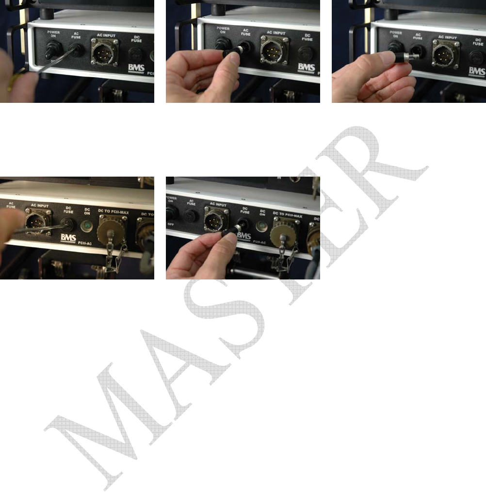
Fuse Replacement Procedure
Tools Needed
Standard Screwdriver
1. Remove the old fuse by using the screwdriver to unscrew the fuse cap on the front panel of the
control panel (see Figure 18 and Figure 19 )
2. Remove the old fuse & dispose.
3. Insert new fuse into the fuse holder.
4. Replace the fuse cap using a screwdriver to secure it in place.
25
Unscrewing the AC Fuse Cap
Removing the AC Fuse Holder
AC Fuse in Holder
Figure 18 Replacing the AC Fuse
Unscrewing the DC Fuse Cap
Removing the DC Fuse Holder
Figure 19 Replacing the DC Fuse
26
WARRANTY
BMS warrants that, at time of delivery, the product will be free from defects in materials and workmanship
provided the equipment or system is installed, operated and maintained in accordance with the Operation
and Maintenance manual or such other BMS documentation as may be applicable. Any such defect
reported to BMS within two years, BMS will take reasonable and prompt action to repair or replace such
equipment.
Should any of the components be defective, please contact BMS immediately. Please have the following
information available so we can best serve you.
• Customer Name
• Contract Number
• BMS Model Number
• Serial Number
• Detailed Description of Problem
• Name of Contact Person.
• Contact Information such as phone number and/or email address.
• Return Information
Much of this information can be found on the product label found on the component.
USA
Serial No.
Model No.
SAN DIEGO, CA.-3V822
Services, Inc.
Microwave
Broadcast
Contract Number or Customer Name
BMS Part/Model Number
Serial Number
Description and special customer
related specification
Figure 20 Product Label
Defective components under BMS warranty will be repaired/replaced promptly at the discretion of BMS.
Items no longer under warranty will require a PO before repairs can proceed.
NOTE:
All goods returned for service require an RMA #. Any goods received without an RMA# may not
be processed in a timely manner. Please contact BMS for an RMA#.
Customer Service Information
Broadcast Microwave Services, Inc.
12367 Crosthwaite Circle
Poway, CA 92064
Toll free (US): 800-669-9667
Fax: +1 (858) 391-3049
Email:support@bms-inc.com
Web: www.bms-inc.com

27
This Page Intentionally Left Blank

28
Additional References
US Broadcast Frequency Assignments
Coded Orthogonal Frequency Division Multiplex (COFDM) Modulation
This Page Intentionally Left Blank
29
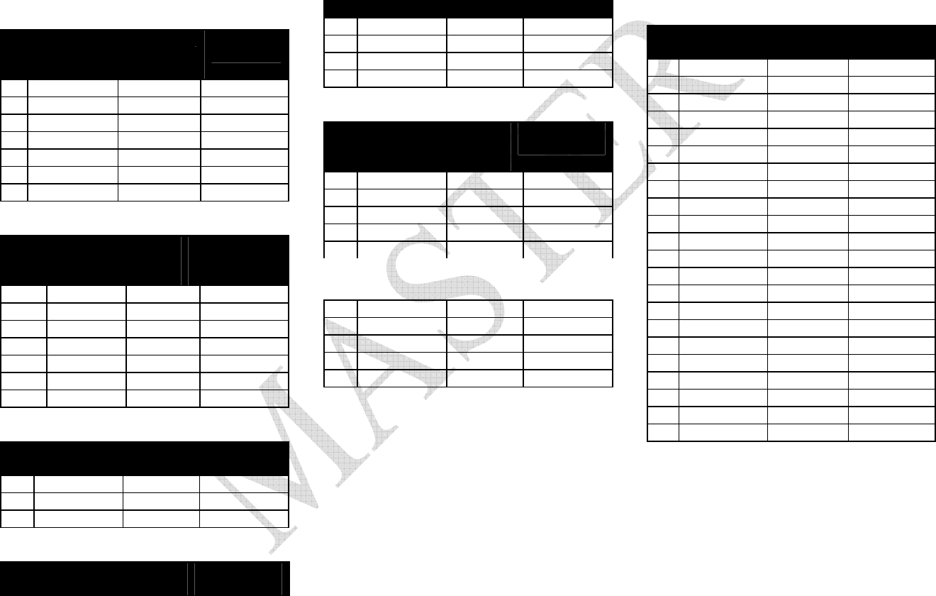
US Broadcast Frequency Assignments
Old BAS Channel Plan
2 GHz (S) Band
1990-2110 MHz
17 MHz CW
1 1994.75 1999.00 2003.25
2 2012.25 2016.50 2020.75
3 2029.25 2033.50 2037.75
4 2046.25 2050.50 2054.75
5 2063.25 2067.50 2071.75
6 2080.25 2084.50 2088.75
7 2097.25 2101.50 2105.75
New BAS Channel Plan
2 GHz (S) Band
1990-2110 MHz
12 MHz CW
12 MHz CS
A1r 2028.50 2031.50 2034.50
A2r 2040.50 2043.50 2046.50
A3r 2052.50 2055.50 2058.50
A4r 2064.50 2067.50 2070.50
A5r 2076.50 2079.50 2082.50
A6r 2088.50 2091.50 2094.50
A7r 2100.50 2103.50 2106.50
2.5 GHz (S) Band
2450-2500 MHz
17 MHz CW
17 MHz CS
8 2454.25 2458.50 2462.75
9 2471.25 2475.50 2479.75
10 2487.75 2492.00 2496.25
6 GHz (C)
Low Band
25 MHz CW
25 MHz CS
6425-6525 MHz
1 6431.00 6437.50 6444.00
2 6456.00 6462.50 6469.00
3 6481.00 6487.50 6494.00
4 6506.00 6512.50 6519.00
7 GHz (C)
High Band
6875-7125 MHz
25 MHz CW
25 MHz CS
1 6881.00 6887.50 6894.00
2 6906.00 6912.50 6919.00
3 6931.00 6937.50 6944.00
4 6956.00 6962.50 6969.00
5 6981.00 6987.50 6994.00
6 7006.00 7012.50 7019.00
7 7031.00 7037.50 7044.00
8 7056.00 7062.50 7069.00
9 7081.00 7087.50 7094.00
10 7106.00 7112.50 7119.00
13 GHz Band
12700-13250 MHz
25 MHz CW
25 MHz CS
1 12706.25 12712.50 12718.75
2 12731.25 12737.50 12743.75
3 12756.25 12762.50 12768.75
4 12781.25 12787.50 12793.75
5 12806.25 12812.50 12818.75
6 12831.25 12837.50 12843.75
7 12856.25 12862.50 12868.75
8 12881.25 12887.50 12893.75
9 12906.25 12912.50 12918.75
10 12931.25 12937.50 12943.75
11 12956.25 12962.50 12968.75
12 12981.25 12987.50 12993.75
13 13006.25 13012.50 13018.75
14 13031.25 13037.50 13043.75
15 13056.25 13062.50 13068.75
16 13081.25 13087.50 13093.75
17 13106.25 13112.50 13118.75
18 13131.25 13137.50 13143.75
19 13156.25 13162.50 13168.75
20 13181.25 13187.50 13193.75
21 13206.25 13212.50 13218.75
22 13231.25 13237.50 13243.75
This Page Intentionally Left Blank

30
Coded Orthogonal Frequency Division Multiplex (COFDM) Modulation
COFDM is used for microwave applications like wireless cameras and mobile video links because of its
tolerance to multipath transmission errors. In addition COFDM offers more than twice the spectral efficiency
of comparable FM analog microwave transmission.
COFDM does not rely on the vulnerability of a single carrier but spreads the digital information over many
narrow band carriers using Frequency Division Multiplex (FDM). The bandwidth and the data rate on each of
these carriers are reduced and therefore the RF robustness is increased. The carriers are accurately spaced and
orthogonal, which means they can be generated and recovered without carrier specific filtering. Even though
the spectra of adjacent carriers significantly overlap, each carrier can be demodulated without crosstalk from
its neighbors.
The main COFDM parameters are:
• Number Of Sub-Carriers (About 2,000 In Our Case)
• The Symbol
• Individual Sub-Carrier Modulation
• Guard Interval (GI) Duration Between COFDM Symbols
• Data Redundancy Code Rate Used For Error Correction
Symbols
The active symbol is the period that digital information is sampled. The number of bits carried in each
symbol depends on the choice of modulation.
Modulation
Modulation is the process of varying a carrier signal in
order to use that signal to convey information.
Quadrature amplitude modulation (QAM) is a
modulation scheme which conveys data by changing (modulating) the amplitude and phase of two carrier
waves. BMS uses the forms QPSK, 16QAM, and 64QAM.
QPSK 2 bits/symbol
16 QAM 4 bits/symbol
64 QAM 6 bits/symbol
The higher-order QAM has a higher susceptibly to noise and other corruption. 64QAM will transmit more
bits per symbol but with higher bit error rate. It is a less robust signal, but over an easy transmission path
(studio setting) it probably won’t matter. More difficult transmission paths (mobile or aerial over long ranges
with lots of interference from trees and buildings) will require a more robust signal.
Guard Interval (GI)
The guard interval acts as a buffer to protect the active symbol from echoes. A guard interval is added to the
beginning of each symbol to allow time for echoes to settle before beginning the active symbol period. A
wide range of guard interval options are available from to . This fraction represents the ratio between the
guard interval to the active symbol period.
This Page Intentionally Left Blank

31
Code Rate
The code rate represents the amount of Forward Error Correction (FEC) used for each active symbol. FEC is
a method of obtaining error control in data transmission. A code rate of ½ means that for two bits of
information received, 1 bit is the real data. The other bit tells how intact the first bit is. A code rate of 7/8
means that out of the 8 bits sent, there are 7 bits of real data and only 1 bit that is to catch any errors in those
7.
Transmission Rates
Finding the best transmission mode to suit a given situation means selecting the best compromise between
modulation, guard interval and code rate. What follows are the ETSI EN 300 744 V1.4.1 (2001-01) standards
for the useful bitrate (Mbit/s) for all combinations of guard interval, constellation and code rate for non-
hierarchical systems for 6, 7, and 8 MHz channels respectively.

Modulation Code
Rate
Transport Rate (Mb/s) at each
Guard Interval for 6 MHz BW Transport Rate (Mb/s) at each
Guard Interval for 7 MHz BW Transport Rate (Mb/s) at each
Guard Interval for 8 MHz BW
1/4 1/8 1/16 1/32 1/4 1/8 1/16 1/32 1/4 1/8 1/16 1/32
1/2 3,7321 4,147 4,391 4,524 4,354 4,838 5,123 5,278 4,98 5,53 5,85 6,03
2/3 4,976 5,529 5,855 6,032 5,806 6,451 6,830 7,037 6,64 7,37 7,81 8,04
3/4 5,599 6,221 6,587 6,786 6,532 7,257 7,684 7,917 7,46 8,29 8,78 9,05
5/6 6,221 6,912 7,318 7,540 7,257 8,064 8,538 8,797 8,29 9,22 9,76 10,05
QPSK
7/8 6,532 7,257 7,684 7,917 7,620 8,467 8,965 9,237 8,71 9,68 10,25 10,56
1/2 7,465 8,294 8,782 9,048 8,709 9,676 10,246 10,556 9,95 11,06 11,71 12,06
2/3 9,953 11,059 11,709 12,064 11,612 12,902 13,661 14,075 13,27 14,75 15,61 16,09
3/4 11,197 12,441 13,173 13,572 13,063 14,515 15,369 15,834 14,93 16,59 17,56 18,10
5/6 12,441 13,824 14,637 15,080 14,515 16,127 17,076 17,594 16,59 18,43 19,52 20,11
16QAM
7/8 13,063 14,515 15,369 15,834 15,240 16,934 17,930 18,473 17,42 19,35 20,49 21,11
1/2 11,197 12,441 13,173 13,572 13,063 14,515 15,369 15,834 14,93 16,59 17,56 18,10
2/3 14,929 16,588 17,564 18,096 17,418 19,353 20,491 21,112 19,91 22,12 23,42 24,13
3/4 16,796 18,662 19,760 20,358 19,595 21,772 23,053 23,751 22,39 24,88 26,35 27,14
5/6 18,662 20,735 21,955 22,620 21,772 24,191 25,614 26,390 24,88 27,65 29,27 30,16
64QAM
7/8 19,595 21,772 23,053 23,751 22,861 25,401 26,895 27,710 26,13 29,03 30,74 31,67
1 Figures in italics are approximate values.

This Page Intentionally Left Blank

GLOSSARY
Analog Transmission Frequency Modulated (FM) method of sending information with radio waves.
An older, dependable method of transmission. (See Digital Transmission)
Antenna Actuator The mechanism which deploys or retracts the antenna radio operation or for
landing and take-off.
ASI: Asynchronous
Serial Interface
Transmission standard used to connect video delivery equipment within a
cable, satellite or terrestrial plant.
BNC Connector The Bayonet Neill-Concelman connector is a type of RF connector used for
terminating coaxial cable. (See TNC connector)
COFDM: Coded
Orthogonal Frequency
Division Multiplex
A digital modulation method that divides a single digital signal across multiple
(1000+) signal carriers simultaneously. BMS Coder II family products use
COFDM digital modulation.
Composite Video The format of an analog television (picture only) signal before it is combined
with a sound signal and modulated onto an RF carrier.
dB: Decibel A unit for expressing the ratio of two amounts of electric or acoustic signal
power equal to 10 times the common logarithm of this ratio.
dBd Gain referenced to a perfect dipole
dBi Gain referenced to a perfect isotropic point source
dBm A unit for expressing the power ratio in decibel (dB) of the measured power
referenced to one milliwatt (mW).
Digital Transmission Digitally Modulated (COFDM and others) method of sending information with
radio waves. Newer more reliable method of transmission. (See Analog
Transmission)
Directional Antenna The final transmit element of a microwave system that radiates the signal one
direction, in a directed or focused narrow beam. This requires aiming of the
antenna toward the receive site.
DTV: Digital Television Digital Television uses digital modulation and compression to broadcast video,
audio and data signals.
DVB-T:
Digital Video
Broadcasting-
Terrestrial
An international digital television (DTV) standard that defines digital COFDM
modulation using MPEG2 compression.
GPS: Global
Positioning System
A navigational system using satellite signals to fix the location of a receiver on
or above the earth surface.
MPEG-2 A compression standard for digital video and audio data.

Multipath The radio wave propagation phenomenon that results in the transmitted
signals. reaching the receiving antenna by two or more paths. This condition is
not desirable and usually results in signal fading and interference.
MUX
Multiplex
The combining of multiple signals into a single transmission.
NIT Network Information Table
Omni-Directional
Antenna
The final transmit element of the microwave system that radiates the signal
approximately equally throughout a 360 degree circle. Does not require aiming
of the antenna.
PAL phase-alternating
line
A color encoding used in broadcast television systems in large parts of the
world.
PAT
Program Association
Table
Indicates which PID the PMT is to be found
PID Packet Identifier
PMT-PID
Program Map Table
Yields information about the Program, Video PID, Audio PID, and PCR PID.
The PMT-PID default is 200 for BMS systems.
PCR-PID
Program Clock
Reference
A time stamp indicating the system time clock value when the stamped packet
leaves the encoder buffer and enters the decoder buffer used to Synchronize
the receiver System Time Clock (STC) with the transmitter STC. Default is 101
for BMS systems.
RF: Radio Frequency That portion of the Electromagnetic Spectrum that is used for radio and
television transmission.
SDI: Serial Digital
Interface
A digitized video format used for broadcast grade video.
SDT Service Description Table
Stand-by The condition of an RF system where all but the transmit circuits are
energized. In this status the system may be switched into transmit mode
instantaneously. (See Transmit)
TNC Connector Threaded version of the BNC connector (See BNC connector)
Transmit The condition of an RF system where it is sending out signal. (See Stand-by)
YUV The YUV model defines a color space in terms of one luminance and two
chrominance components. YUV is used in the PAL system of television
broadcasting, which is the standard in much of the world.