Broadcast Microwave Services HC4-2 Heli-Coder 4 Transmitter User Manual
Broadcast Microwave Services Inc Heli-Coder 4 Transmitter Users Manual
Users Manual
HELI-CODER™ 4 TRANSMITTER
Operation Manual
Doc. No. 6051452100 Rev.B1
Broadcast Microwave Services, Inc. | www.bms-inc.com
Corporate Headquarters
12367 Crosthwaite Circle | Poway, CA 92064 US
Phone: +1 800-669-9667 (US) | +1 (858) 391-3050 | Fax: +1 (858) 391-3049
BMS European Office
Schwalbacherstr. 12 | 65321 Heidenrod-Kemel GERMANY
Phone: +49-6124-7239-00 | Fax: +49-6124-7239-29
2012 Broadcast Microwave Services. All rights reserved.
This document and the information contained in it is the property of Broadcast Microwaves Services, Inc. and may be the subject
of patents pending and granted. It must not be used for commercial purposes nor copied, disclosed, reproduced, stored in a
retrieval system or transmitted in any form or by any means (electronic, mechanical, photocopying, recording or otherwise),
whether in whole or in part, without BMS prior written agreement.
This printed document is uncontrolled and is for reference only. Users are to verify that this is the latest approved version.
Heli-Coder 4 Transmitter Operation Manual | Doc. No. 6051452100 Rev. B1
Broadcast Microwave Services, Inc. i
Document Revision History
DRAFT November 2011
Preliminary Release April 2012
Preliminary Update May 2012
Initial Release June 2012 Rev -
Add Additional Figures and Software Installation Section. December 2012 Rev A
Amend DO-160 compliance table July 2013 Rev B
Amend for FCC compliance Sept 2013 Rev B1
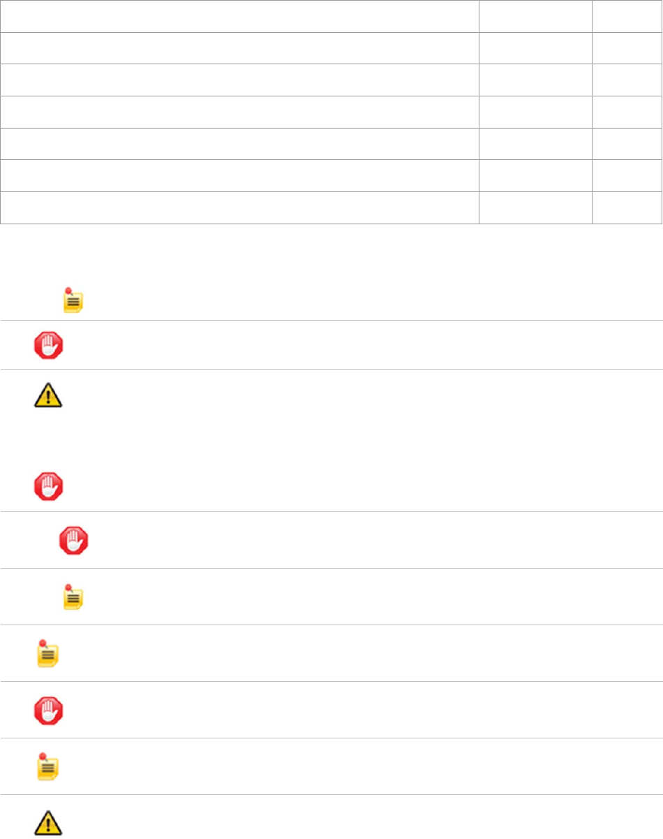
Conventions Used in This Manual
1.
NOTE: Notes provide supplementary information. They are highlighted for emphasis, as in this example, and
are placed immediately after the relevant text.
CAUTION: Cautions give information which, if strictly followed, will prevent damage to equipment or other
goods. They are boxed for emphasis, as in this example, and are placed immediately preceding the point at
which the reader requires them.
WARNING: Warnings give information which, if strictly observed, will prevent personal injury or death, or
damage to personal property or the environment. They are boxed and shaded for emphasis, as in this example,
and are placed immediately preceding the point at which the reader requires them.
2. ATTENTION!
DO NOT use right-angle connectors or adapters on the RF Power Out cable assemblies. Right-angle
connectors may have significant RF power loss at the operating frequencies of this system.
3.
FOR ALL BMS TRANSMITTERS – Operation of a BMS transmitter product generally requires a license. It is the
responsibility of the user to obtain all required operating licenses.
4.
ONLY FOR PRODUCTS AWAITING FCC CERTIFICATION – This device has not been authorized as required
by the rules of the US Federal Communications Commission. This device is not, and may not be, offered for
sale or lease, or sold or leased, in the US until authorization is obtained.
Acceptance Test Procedure (ATP) test data results by product serial number are typically shipped with all units
and indicate the equipment to be operating within advertised specifications. Contact BMS to request this data.
Read and Follow Instructions! All safety and operating instructions should be read before this product is
operated. All operating and use instructions should be followed. This manual should be retained for future
reference.
EMC Compliance – This equipment is certified to the EMC requirements detailed in the technical specifications.
To maintain this certification, only use the cables supplied or if in doubt contact BMS Customer Service.
RF Exposure Information – For body worn operation, the device has been tested and meets FCC RF exposure
guidelines when used with an accessory that contains no metal and that positions device a minimum of 7.9” (20
cm) from the body. Use of other accessories may not ensure compliance with FCC RF exposure guidelines.
Broadcast Microwave Services, Inc. ii
PAGE INTENTIONALLY LEFT BLANK
Broadcast Microwave Services, Inc. iii
Contents
1INTRODUCTION .............................................................................................................................................. 1
2SAFETY ............................................................................................................................................................ 2
3PRODUCT DEFINITION ................................................................................................................................... 4
3.1Product Specifications .............................................................................................................................. 2
3.2Model Information ..................................................................................................................................... 2
4CONNECTORS AND PINOUTS ....................................................................................................................... 3
5INSTALLATION ................................................................................................................................................ 7
5.1Locating the Components ......................................................................................................................... 7
5.2Fasteners ................................................................................................................................................. 8
5.3Mounting the Transmitter.......................................................................................................................... 8
5.4Wiring Connections and Signal Interfaces .............................................................................................. 11
5.4.1Power Input (J2) ...................................................................................................................................................... 11
5.4.2Radio Frequency Output (RF Out) (J5) .................................................................................................................. 11
5.4.3Serial Digital Video Input (J12) ................................................................................................................................ 11
5.4.4Composite Video (CVBS) Input (J9) ........................................................................................................................ 11
5.4.5ASI Input .................................................................................................................................................................. 11
5.4.6ASI Output ............................................................................................................................................................... 11
5.4.7Audio Input .............................................................................................................................................................. 11
5.4.8GPS ......................................................................................................................................................................... 12
5.4.9Data Wayside Input ................................................................................................................................................. 12
5.4.10KLV Data ............................................................................................................................................................ 12
5.4.11Auxiliary Data ..................................................................................................................................................... 12
5.4.12Ethernet .............................................................................................................................................................. 12
5.4.13USB .................................................................................................................................................................... 12
5.4.14ARINC ................................................................................................................................................................ 12
5.4.15Control ................................................................................................................................................................ 13
6TRANSMITTER OPERATION ........................................................................................................................ 14
6.1Operating the Transmitter with the DLC50 Control Panel ...................................................................... 14
6.2DLC50 Menu Structure ........................................................................................................................... 15
7BMS Geo-Point™ System ............................................................................................................................. 17
7.1Geo-Point System Description ............................................................................................................... 17
7.2Enabling Geo-Point™ ............................................................................................................................. 17
8SOFTWARE INSTALLATION ........................................................................................................................ 18
9ACCESSORIES .............................................................................................................................................. 19
10ADDITIONAL REFERENCES ........................................................................................................................ 19
11REGULATORY ............................................................................................................................................... 20
11.1Electromagnetic Compliance .................................................................................................................. 20
11.2FCC ........................................................................................................................................................ 20
11.3Environmental Qualifications .................................................................................................................. 20
12PREVENTIVE MAINTENANCE ...................................................................................................................... 21
12.1Maintenance Schedule ........................................................................................................................... 21
12.2Maintenance Procedures........................................................................................................................ 21
12.3Spare Parts ............................................................................................................................................ 21
13REPAIR SERVICE AND WARRANTY ........................................................................................................... 21
13.1Customer Service ................................................................................................................................... 22
14GLOSSARY .................................................................................................................................................... 23
15CONNECTION AND WIRING DIAGRAMS .................................................................................................... 25
Broadcast Microwave Services, Inc. iv
List of Figures
Figure 1. Heli-Coder 4 Transmitter ............................................................................................................................ 4
Figure 2 HC4 Front Panel Labels .............................................................................................................................. 3
Figure 3 Transmitter mounting bracket ..................................................................................................................... 8
Figure 4 HC4 positioned in aircraft mounting bracket ................................................................................................ 8
Figure 5 HC4 Outline Drawing ................................................................................................................................... 9
Figure 6 CT-A-MP HC4 Mounting Plate - Dimensioned Drawing ............................................................................ 10
Figure 7 DLC50-A AVIONICS CONTROL PANEL (FRONT) ................................................................................... 14
Figure 8 DLC50-A AVIONICS CONTROL PANEL (BACK) ...................................................................................... 14
Figure 9 DLC50 Commands .................................................................................................................................... 15
Figure 10 DLC50 Outline ......................................................................................................................................... 16
Figure 11 Product Label ........................................................................................................................................... 22
Figure 12 Typical airborne installation diagram (without TAA-101 Antenna Actuator) ............................................. 26
Figure 13 Wire Hook-Up Diagram for HC4 System (without TAA-101 Antenna Actuator) ....................................... 27
Figure 14 Typical airborne installation diagram (including TAA-101 Antenna Actuator) .......................................... 28
Figure 15 Wire Hook-Up Diagram for HC4 System (including TAA-101 Antenna Actuator) .................................... 29
List of Tables
Table 1 MPE per FCC OET65 (1.5 GHz to 100 GHz) ................................................................................................ 3
Table 2. Product connector descriptions in Figure 1 .................................................................................................. 4
Table 3. HC4 connectors ........................................................................................................................................... 3
Table 4. Connector pin outs ....................................................................................................................................... 4
Table 5. HC4 Component Placement Planning ......................................................................................................... 7

Heli-Coder 4 Transmitter Operation Manual | Doc. No. 6051452100 Rev. B1
Broadcast Microwave Services, Inc. 1
1 INTRODUCTION
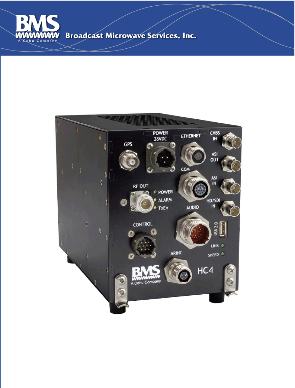
This document provides instructions for installation, operation and maintenance of the Heli-Coder 4 (HC4) COFDM
Transmitter controlled by a DLC50 Downlink Control Panel.
BMS offers a wide selection of airborne products to meet the video and data requirements of today’s real world
applications. The Heli-Coder™ 4 (HC4) together with the DLC50 controller provides a simple, powerful solution
containing everything needed for high-quality, reliable transmission. This includes the video encoder, modulator,
up-converter and high-power amplifier and an intuitive powerful control interface (see Figure 1.).
Standard COFDM modulation offers excellent performance in urban and non-line of sight environments with
significant multipath. The HC4 also provides an integrated GPS data interface that reduces the components
needed to integrate location data into tracking systems. The HC4 provides everything required to achieve 10 W
output power in an ultra-compact case. The DLC50 control panel allows the HC4 unit to be mounted remotely
within the avionics bay while providing full control from the flight deck.
With the flexibility of MPEG-2 and H.264 compression, the HC4 efficiently handles SD or HD video and can be
configured to deliver high speed data as an ethernet radio. The HC4 is also Geo-Point™ capable. Geo-Point™
uses metadata supplied by the equipment serving as the video source and allows the display of bearing and
distance to the location shown on the screen in real time. (Geo-Point™ requires a compatible receiver.)
NOTE: The standard version of the HC 4 is configured to be controlled by a DLC50 Control Panel. Custom
configurations and control schemes may be supported. Contact BMS regarding your operational requirements and
the range of solutions BMS offers.
Broadcast Microwave Services (BMS) is a leader in wireless digital microwave technology providing innovative
products for the television broadcast, video, telemetry and surveillance industries. A wholly owned subsidiary of
Cohu, Inc., BMS designs and manufactures a comprehensive line of microwave communications equipment for
broadcasting sports venues, law enforcement and military applications. BMS also builds and integrates the
command and control centers to provide fully functioning, complex, end to end digital systems.
For the latest product and system information please visit www.bms-inc.com.
Broadcast Microwave Services, Inc.
12367 Crosthwaite Circle
Poway, CA 92064
Tel: +1 (858) 391-3050
Toll free (US): 800-669-9667
Fax: +1 (858) 391-3049
Email:sales@bms-inc.com
www.bms-inc.com
Heli-Coder 4 Transmitter Operation Manual | Doc. No. 6051452100 Rev. B1
Broadcast Microwave Services, Inc. 2
2 SAFETY
WARNING- RF Hazard: Non-Ionizing RF Emission
Operators of this equipment should be familiar with basic RF equipment operation and safety concepts. Users
must consider many unique factors to maintain RF safety. We offer the following guidelines with the
recommendation that each individual and organization establish an RF Safety and Awareness program based on
their combination of hardware and usage environment.
Radiation Exposure
The frequencies present in BMS equipment produce non-Ionizing radiation. The FCC reference document
regarding RF exposure limits is OET Bulletin 65 and can be viewed by visiting the FCC web site (www.fcc.gov ) or
by clicking here;
http://www.fcc.gov/Bureaus/Engineering_Technology/Documents/bulletins/oet65/oet65.pdf
(Link valid as of 9/18/2013)
We also reference EU Standard EN 50392 (02-2004). BMS references these standards as reasonable guidelines.
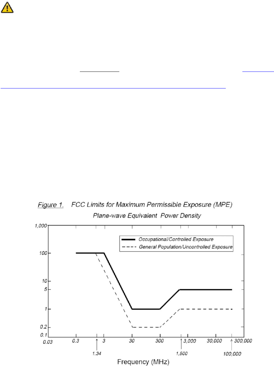
The OET 65 document sets maximum permitted exposure (MPE) and is widely cited within the U. S. and Canada.
Exposure is divided into two categories, “controlled” and “uncontrolled” environment. The uncontrolled
environment is the harshest criteria and applies to exposure where you may not be aware and/or cannot control
the exposure. Examples are where a residence is located near a cell site or other radio tower. You live there,
cannot remove yourself from the field and cannot control the RF. Exposure is long term and not in your control.
The “controlled environment” applies to most professional radio users. It is assumed they are trained in RF Safety,
they are aware there is an RF field, exposure is limited by transmission duty cycles, the flight or testing ends, hang
up the cell phone, put up the walkie-talkie, etc.
BMS recommends that operators use the uncontrolled exposure category from OET 65 as it applies to an
uncontrolled environment; a maximum power density limit of 1mW/cm².
The limit table from Bulletin 65 is reproduced below. X axis is frequency and y axis is mW/cm².

Heli-Coder 4 Transmitter Operation Manual | Doc. No. 6051452100 Rev. B1
Broadcast Microwave Services, Inc. 3
Use the formula from OET65 to determine the minimum recommended distance according to your individual usage
circumstances.
Your organization should develop an understanding of its unique RF usage and create a plan to train personnel
regarding recommended exposure limits according to the FCC and EU recommendations.
General Safety Rules;
a) Do not operate the transmitter or power amplifier with covers removed.
b) Never walk in front of directional antennas when radiating.
c) Switch off supplies before removing covers or disconnecting any RF cables, and before inspecting damaged
cables or antennas.
d) BMS recommends returning the HC4 to the factory for service or repair.
In addition you can limit your exposure by raising awareness and using some common sense rules.
Default to low power if available using hi-power only as required.
Never stand in front of a transmitting directional antenna.
Limit transmission duty cycles (turn on/off as needed).
Table 1 MPE per FCC OET65 (1.5 GHz to 100 GHz)
TRANSMITTER OUTPUT (w) 10
ANTENNA GAIN dBi 0 2 4 6 9 11 14 22
UNCONTROLLED ENVIRONMENT:
MINIMUM PERMISSABLE
DISTANCE INCHES
1.005 mW/cm2
11.08 13.95 17.56 22.10 31.22 39.31 55.52 139.47
CONTROLLED ENVIRONMENT:
MINIMUM PERMISSABLE
DISTANCE INCHES
(5.005 mW/cm2)
4.96 6.25 7.87 9.91 13.99 17.61 24.88 62.50
NOTE: Calculations do not factor reflections
Heli-Coder 4 Transmitter Operation Manual | Doc. No. 6051452100 Rev. B1
Broadcast Microwave Services, Inc. 4
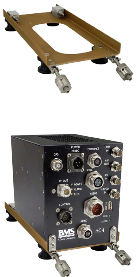
3 PRODUCT DEFINITION
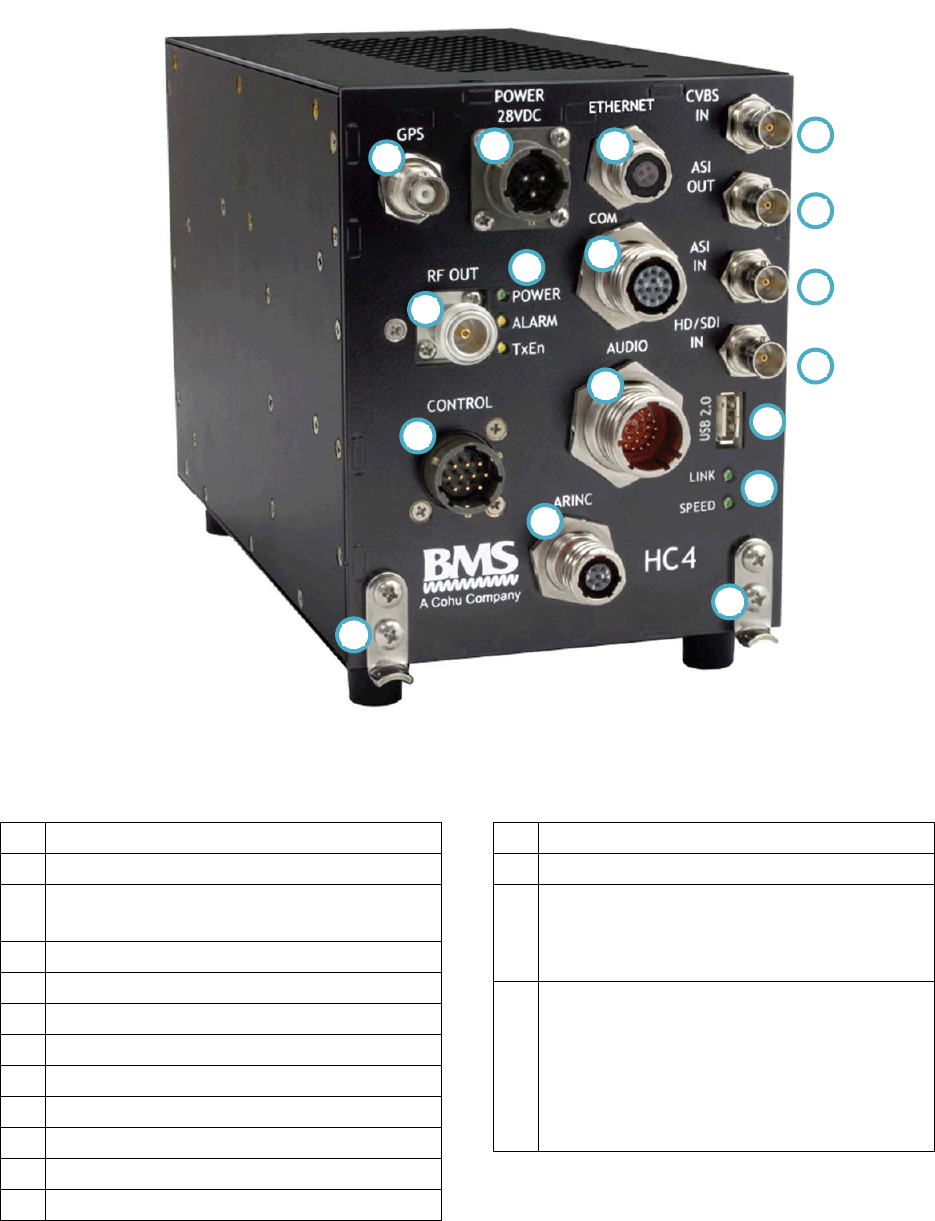
Figure 1. Heli-Coder 4 Transmitter
Table 2. Product connector descriptions in Figure 1
1GPSAntennaInput
228VDCPower
3Ethernetport
4CommunicationsPortConnector–RS‐232
5RFOutput(N‐type)
6AudioInput
7ControlcableInput(fromDLC50ControlPanel)
8ARINCConnector(Reservedforfutureuse)
9AnalogVideoInput(CVBScompositevideo)
10ASI(AsynchronousSerialInterface)videoout
11ASI(AsynchronousSerialInterface)videoin
12HD/SDI(Digital–uncompressed)videoin
13USB2.0port
14Mountingbracket(x2)
15
EthernetStatusIndicators:YellowSPEEDLED:
ON=100BaseT,OFF=10BaseTGreenLINKLED:
Flashing=ValidEthernetLink,Off=NOValid
EthernetLink
16
PowerLED:YELLOWwhenpowercable
pluggedin;GREENwhenunitturnedonvia
DLC50ControlPanel
AlarmLED:YELLOWindicatesatransmit
problem
TxEnLED(TransmitEnabled):YELLOWmeans
Standbymode;GREENmeanstransmitteractive
9
10
11
12
5
2 3
1
4
6
7
8
13
14
16
15
14

Heli-Coder 4 Transmitter Operation Manual | Doc. No. 6051452100 Rev. B1
Broadcast Microwave Services, Inc. 2
3.1 Product Specifications
Frequency 2000-2500 MHz
Channel Bandwidth 8 MHz
RF Output Power
5W/10W nominal switchable
< 12W from 2025-2110 MHz and 2450-2483.5 MHz
Modulation Digital COFDM
Video Encoding H.264/MPEG2
Audio Encoding MPEG 1, Layer II
Channels Two audios, multiple wayside data channels up to 115kbit/s
Internal Test Generator Video/Audio Test pattern
Local Control External Control Panel
Power Input 24 to 32 VDC (3 A @ 28 VDC)
Consumption 85 W @ RF-Output 10 W
Compliance CE marked in accordance with EU Low Voltage and EMC Directives
EMC Compliance: EN55022, EN55024
Operating Temp. -15 to +55° C (5 to +131° F)
Storage Temp. -55 to +85° C (-67 to +185° F)
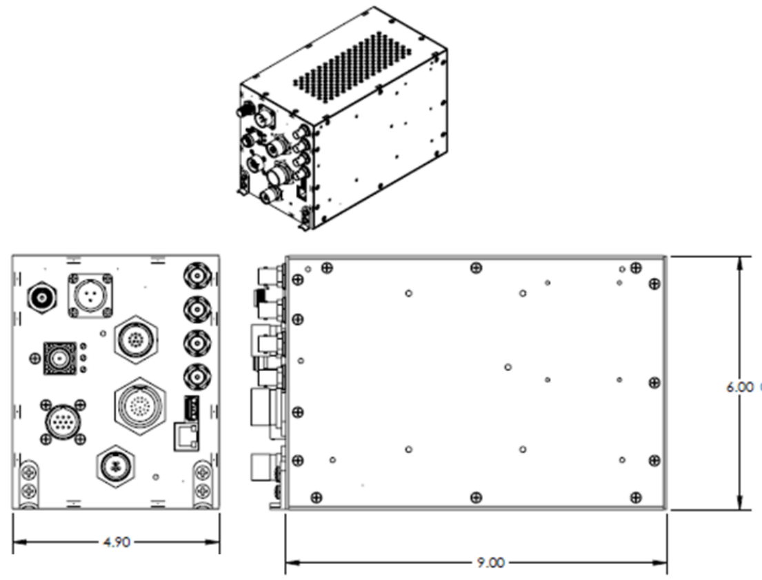
Dimensions 5“ W x 9“ D x 6“ H; 270 in.2 (127 x 229 x 153) mm
Weight 6 lbs. (2.73 kg)
FCC
This device has not been authorized as required by the rules of the Federal
Communications Commission. This device is not, and may not be, offered for
sale or lease, or sold or leased, until authorization is obtained.
FCC (Part 74) product certification pending.
Regulatory
(See section 10)
FCC Certification (pending)
RTCA DO-160, designed to be compliant
CE Mark
3.2 Model Information
PART NO. MODEL PROFILE
HC4-(xx)-H H.264, SD/HD SD=MP@L4 | HD=MP@L4; HP@L4
HC4-(xx)-M MPEG2, SD/HD SD=SP@ML; 422@ML | HD=SP@HL
HC4-(xx)-MH MPEG2/H.264, SD/HD MPEG2: SD=SP@ML; 422@ML | HD=SP@HL
H.264: SD=SP@L4; HI422@L4 | HD=SP@L4
where (xx) is center frequency in MHz
Heli-Coder 4 Transmitter Operation Manual | Doc. No. 6051452100 Rev. B1
Broadcast Microwave Services, Inc. 3
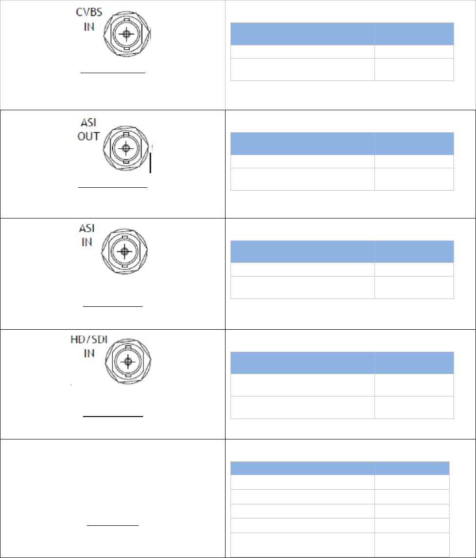
4 CONNECTORS AND PINOUTS
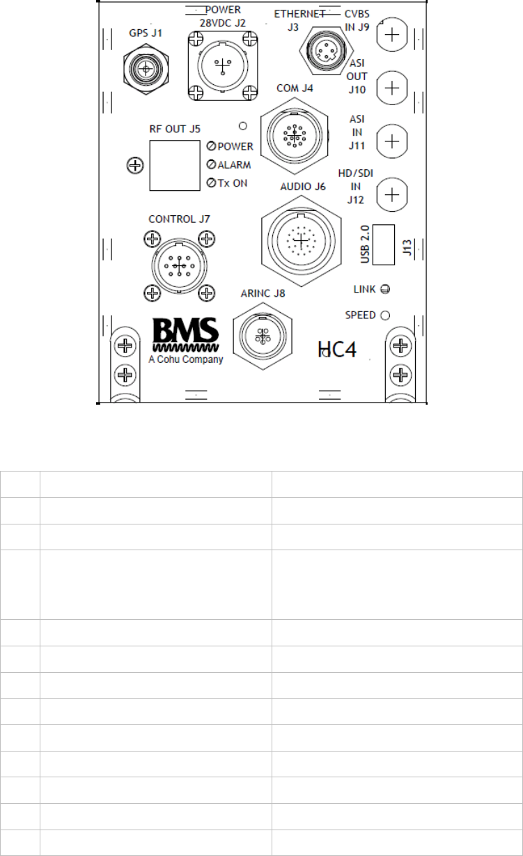
Figure 2 HC4 Front Panel Labels
Table 3. HC4 connectors
J1 GPS In (with optional DC Bias Out) TNC(f), 50 ohm
J2 Power In Souriau 3-pin male 851-02R12-3P50
J3 Ethernet M12-4 Socket (early model used RJ45)
J4
COMM
RS232 External GPS
RS232 External AAAP
RS232 KLV or Camera Metadata
Tri-Start, Size 11, 13 Socket
J5 RF Out N(f), 50 ohm
J6 Analog Audio In (2 channels) D38999-26WC, 35 pin
J7 Control Panel Souriau (male) 10-pin
J8 ARINC 429 (reserved for future use) D38999-26 WA355N socket
J9 CVBS In (NTSC, PAL) BNC(f), 75 ohm
J10 ASI Out BNC(f), 75 ohm
J11 ASI In BNC(f), 75 ohm
J12 SDI, HD-SDI In BNC(f), 75 ohm
J13 USB 2.0 Type A (Host)
Heli-Coder 4 Transmitter Operation Manual | Doc. No. 6051452100 Rev. B1
Broadcast Microwave Services, Inc. 4
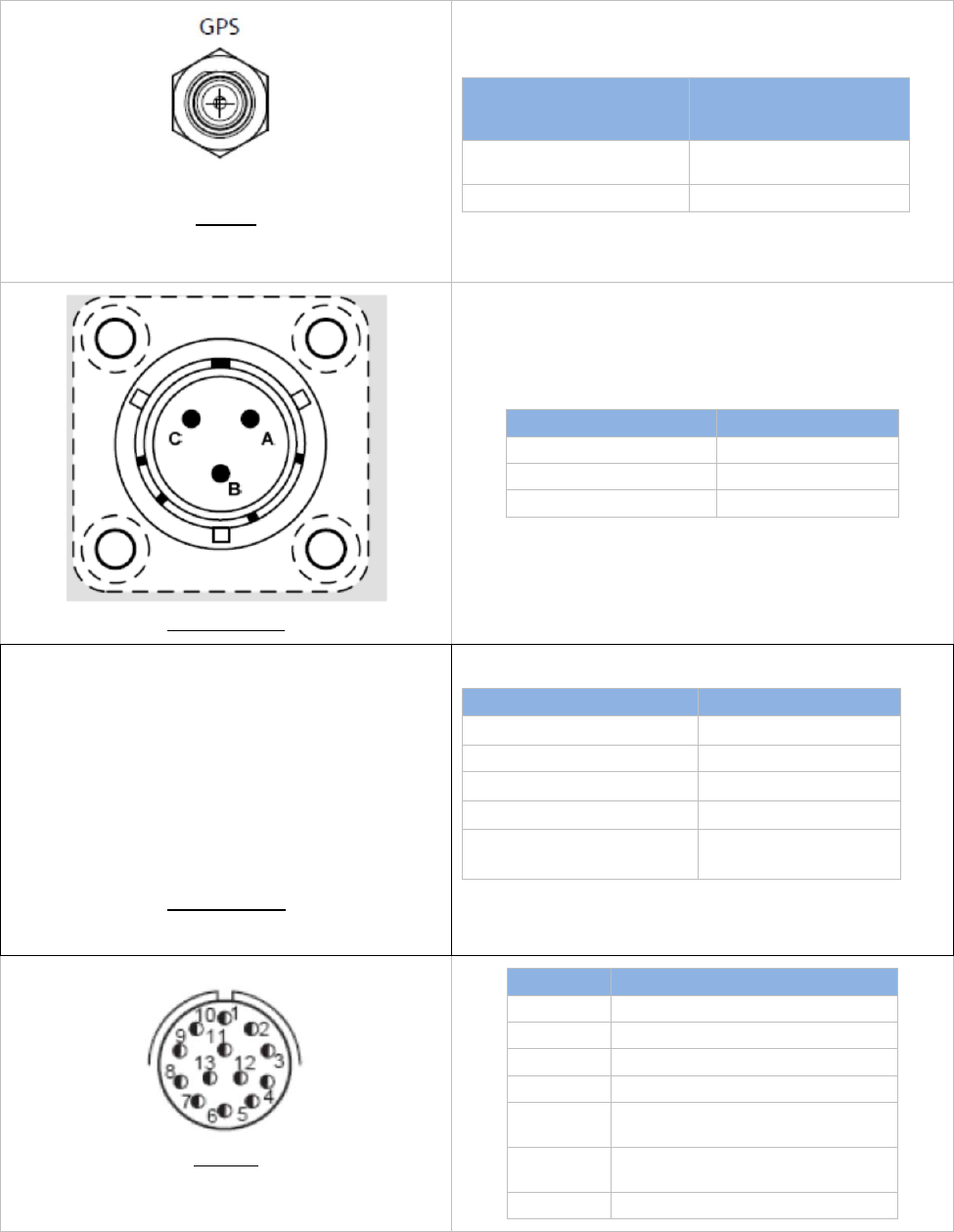
Table 4. Connector pin outs
GPS J1
610006040, TNC(f), 50 ohm
GPS ANTENNA INPUT
TNC CONN (FEMALE)
50 OHM
HC4
Provides variable DC
bias or none.
SIGNAL
SHIELDING GND
Power Input J2
3-pin SOURIAU (m) HC 4
A 28VDC
B GND
C N/C
ETHERNET J3
M12-4, 4 pin socket
USB 2.0 SERIAL DATA HC4
SOCKET 1
TD+
SOCKET 2 RD+
SOCKET 3
TD-
SOCKET 4
RD-
SHIELDING
GROUND
COM J4
210069751, Connector Tri-start, Size 11, 13 Socket,
PCB Tail
COM HC4
1 GND
2 AERO RS232 TX
3 AERO RS232 RX
4 GND
5 TGT DATA RS232 TX, (KLV
Data Tx)
6 TGT DATA RS232 RX (KLV
Data Rx)
7-13 DO NOT USE
Heli-Coder 4 Transmitter Operation Manual | Doc. No. 6051452100 Rev. B1
Broadcast Microwave Services, Inc. 5
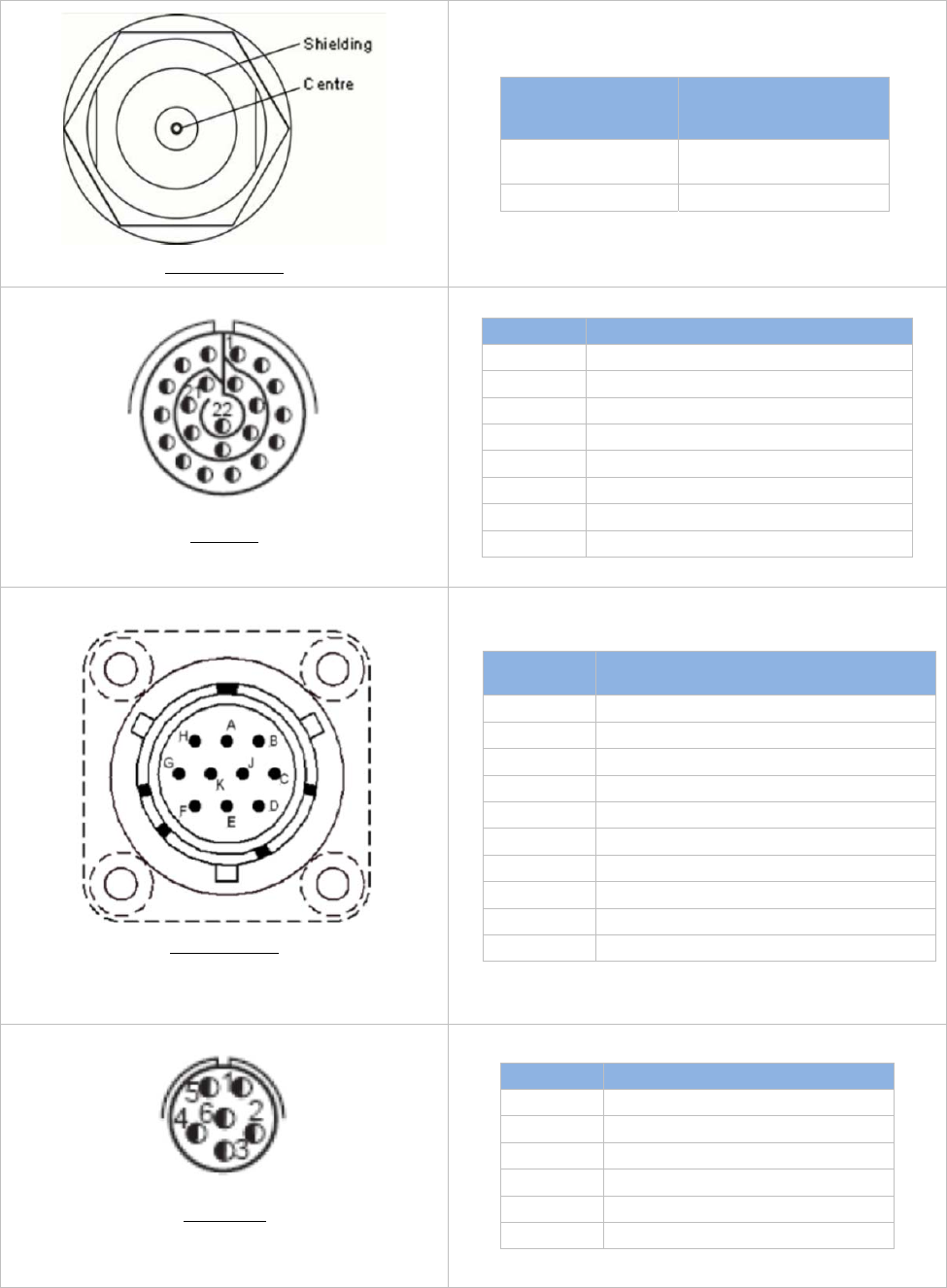
RF OUTPUTJ5
RF OUTPUT N-
CONN(FEMALE)
50 OHM
HC4
UP TO 10W RF
OUT COFDM SIGNAL
SHIELDING GND
Audio J6
210069752, Connector Tristart size 13, 22Pin PC-tails
AUDIO HC4
1 AUDIO 1 L GND
2 AUDIO 1 L+
3 AUDIO 1 L-
4 AUDIO 1 R GND
5 AUDIO 1 R+
6 AUDIO 1 R-
7-12 N.C.
13-22 DO NOT USE
CONTROL J7
210004408, Connector Size 12, 10 Pins, PCB Tails
CONTROL
PANEL HC4
A LOOP_OUT (RAW 28V OUT)
B LOOP_IN (28V FROM DLC50)
C NC
D Remote control Rx
E GND
F Remote control TX
G GND
H NC
J NC
K NC
ARINC J8
210069750,Connector, Tri_Start, Size 9, 6 Socket,
PCB tail
ARINC HC4
1 AOUT (ARINC 429 bus Tx)
2 BOUT (ARINC 429 bus Tx)
3 RIN A (ARINC 429 bus Rx)
4 RIN B (ARINC 429 bus Rx)
5 GND
6 GPS DATA Rs232RX
Heli-Coder 4 Transmitter Operation Manual | Doc. No. 6051452100 Rev. B1
Broadcast Microwave Services, Inc. 6
CVBS INPUT J9
BNC(f), 75 ohm
COMPOSITE VIDEO INPUT
BNC CONN(FEMALE) 75 OHM
HC4
May be NTSC or PAL SIGNAL
SHIELDING
GROUND
ASI OUTPUT J10
BNC(f), 75 ohm
ASI SERIAL DATA OUTPUT
BNC CONN(FEMALE) 75 OHM
HC4
DVB-ASI SIGNAL SIGNAL
SHIELDING
GROUND
ASI INPUT J11
BNC(f), 75 ohm
ASI SERIAL DATA INPUT BNC
CONN(FEMALE) 75 OHM
HC4
DVB-ASI SIGNAL SIGNAL
SHIELDING
GROUND
SDI INPUT J12
BNC(f), 75 ohm
HD OR SD SDI INPUT BNC
CONN(FEMALE) 75 OHM
HC4
SERIAL DIGITAL VIDEO
SIGNAL
SIGNAL
SHIELDING
GROUND
USB 2.0 J13
USB Type A socket
USB 2.0 SERIAL DATA HC4
SOCKET 1
+5 VDC
SOCKET 2
Data -
SOCKET 3
Data +
SOCKET 4
Ground
SHIELDING
GROUND

Heli-Coder 4 Transmitter Operation Manual | Doc. No. 6051452100 Rev. B1
Broadcast Microwave Services, Inc. 7
5 INSTALLATION
Installation should only be performed by an FAA Certified A/P or Avionics Technician.
The HC4 and associated equipment should be installed in compliance with FAA regulations and accepted industry
practices.
Other than allowing adequate air circulation above and below the transmitter, there are no set standards for
placement of the HC4 equipment. The information in Table 5 is a guide for choosing the best placement for each
component. Every aircraft installation is different, with unique interior space requirements to meet the needs of the
pilot, operator and passengers. It is left to the customer to review the size, space, cable and ergonomic needs to
best determine where the components should be installed.
The HC4 may be ordered with the HC4-CONN-KIT which contains all mating connectors except those
locally available (BNC, N, and USB). Alternatively BMS will supply a partially assembled wiring harness upon
order request.
Consult BMS regarding custom cable requirements
5.1 Locating the Components
Table 5. HC4 Component Placement Planning
Component Space Requirement Wt Suggested
Location Connecting
Component
DLC50 Primary
Airborne Control
Panel
4.9 in. x 5.75 in. x 1.5 in.
12.4 cm x 14.6 cm x 3.8 cm
<1 lb
<.45 kg
Cabin, near
operator
HC4
2 AMP BREAKER
(IF SUPPLIED) TAA-
101
HC4 TRANSMITTER
(with CT-A-MP
mounting tray)
5“ W x 9“ D x 6“ H
(127 x 229 x 153 mm)
6 lb
2.72 kg
Usually baggage
compartment but
varies. Allow
ventilation space
above and below
transmitter
DLC50
Video-in
Audio-in
10 AMP BREAKER
GA-35
MAIN ANTENNA
RS-232 DATA IN
KLV DATA IN
GA-35 GPS Antenna
Unobstructed View
5 in. x 3 in. footprint
12.7 cm x 7. 6cm
.25 lb
0.11 kg
Top Exterior
Tail (Varies) HC4
Bulkhead Feed-Thru
Customer Furnished Varies Exterior Location
(Varies) RF Antenna
Heli-Coder 4 Transmitter Operation Manual | Doc. No. 6051452100 Rev. B1
Broadcast Microwave Services, Inc. 8
5.2 Fasteners
Installation of the HC4 is unique to every aircraft. It is left to the installer to provide the properly certified fasteners
for the application.
5.3 Mounting the Transmitter
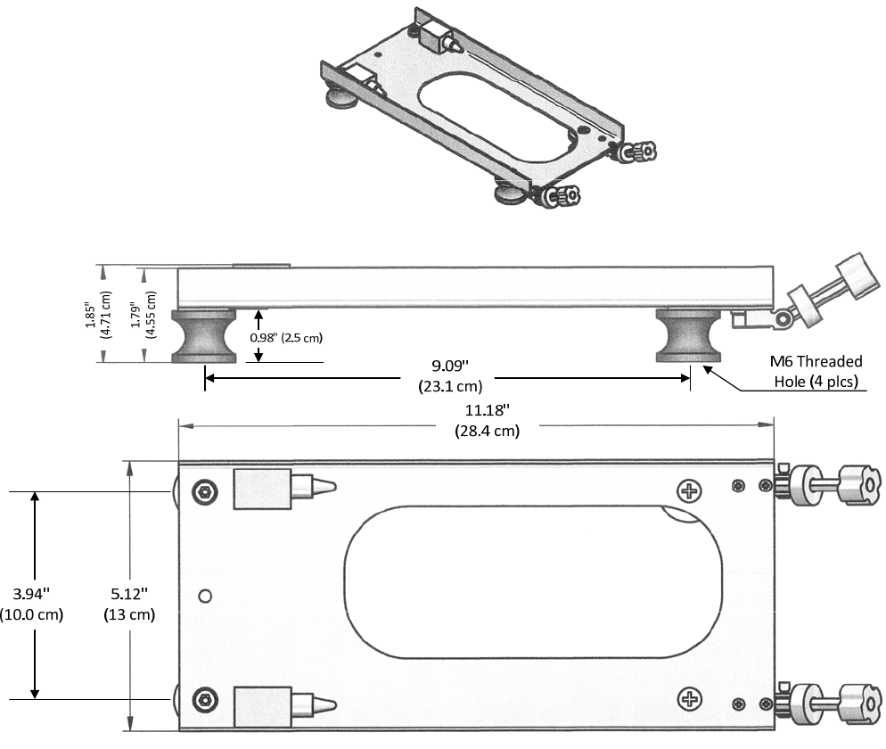
The HC4 transmitter should be mounted in aircraft or other craft using the BMS-supplied mounting bracket (BMS
P/N 4414414000). The transmitter/bracket assembly must have adequate space above and below the unit to
allow free air flow. Three thermostatically controlled fans contained within the HC4 chassis keep the unit at
operating temperature.
1. Place the transmitter so that the two holes on its rear side fit the pins on the mounting bracket.
2. Tighten the mounting screw fasteners. Ensure the round nut captures the mounting bracket on the transmitter.
Figure 3 Transmitter mounting bracket
Figure 4 HC4 positioned in aircraft mounting bracket
Heli-Coder 4 Transmitter Operation Manual | Doc. No. 6051452100 Rev. B1
Broadcast Microwave Services, Inc. 9
Figure 5 HC4 Outline Drawing
Heli-Coder 4 Transmitter Operation Manual | Doc. No. 6051452100 Rev. B1
Broadcast Microwave Services, Inc. 10
Figure 6 CT-A-MP HC4 Mounting Plate - Dimensioned Drawing

Heli-Coder 4 Transmitter Operation Manual | Doc. No. 6051452100 Rev. B1
Broadcast Microwave Services, Inc. 11
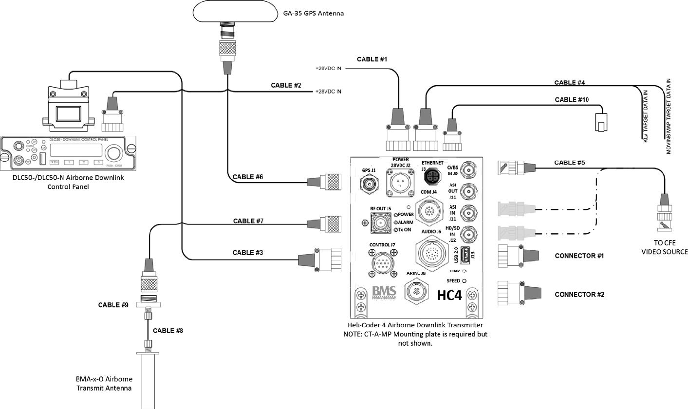
5.4 Wiring Connections and Signal Interfaces
Reference Figure 12 Typical airborne installation diagram (without TAA-101 Antenna Actuator)” and Figure 13 Wire
Hook-Up Diagram for HC4 System” shown later in this document. Also reference section 16 of this manual titled
“CONNECTION AND WIRING DIAGRAMS” during installation for detail related to a typical installation.
Contact BMS regarding issues related to custom or modified installations if applicable. Additional service or fees may
apply.
5.4.1 Power Input (J2)
J2 connects aircraft 28VDC from an available 5 AMP breaker. Use AWG 20 gauge wire or larger.
5.4.2 Radio Frequency Output (RF Out) (J5)
J5 conducts the radio frequency energy out to a transmit antenna. Achieving optimum link performance
includes assuring a maximum RF energy is delivered to the antenna assembly via properly mated connector
assemblies and well installed cables. RF cable should be 50Ω foam dielectric coaxial cable. Belden type FSJ-50A or
equal is recommended. Cable lengths should be as short as practical in the installation to reduce RF loss. Observe
the cable manufacturer’s minimum “bend radius” recommendation during installation. Kinks, pinches, or sharp bends
in high frequency cable will cause significant power losses. Check all connections for proper termination and use
high-quality type N connectors. Hand-tighten connectors; do not use a wrench or pliers as over-tightening will damage
a connector and reduce the system performance by introducing RF loss in the transmission line. Seal mated exterior
connections with self-vulcanizing rubber tape in order to avoid moisture in the connection joint which may also
introduce RF loss or physically damage the connector over time.
It is good practice to avoid the use of 90° elbow adaptors within the RF coax cable run.
5.4.3 Serial Digital Video Input (J12)
J12 is a standard 75Ω BNC jack that is for a Serial Digital Interface. This is the digital video signal that comes out of
most modern video cameras. The signal may be standard definition SDI (SMPTE-270) or high definition HD-SDI
(SMPTE-292). A high quality, double shielded coaxial video cable should be used such as Belden 8281 or equal.
Take care to terminate the cable with a 75Ω BNC plug.
5.4.4 Composite Video (CVBS) Input (J9)
J9 accepts a standard definition composite video signal (PAL or NTSC). Follow the same cabling instructions as in
5.4.3.
5.4.5 ASI Input
J11 accepts an asynchronous serial input (ASI) also known as DVB-ASI (digital video broadcasting). The signal
consists of a compressed MPEG transport stream. The input by-passes the internal encoder built into the HC4 and
goes right into the modulator. This allows use of external video or data encoders whose outputs are an ASI transport
stream. The input must conform to the ISO/IEC 13818-1 standard. Follow the same cabling instructions described
in section 5.4.3.
5.4.6 ASI Output
J10 ports out an ASI transport stream consisting of the encoded video currently being transmitted by the HC4. This
output allows external monitoring of the compressed signal and the use of a backup transmitter or other configurations.
Follow the same cabling instructions described in section 5.4.3.
5.4.7 Audio Input
J6 is a multi-pin connector where pins 1-6 are dedicated to two balanced audio channels, each 600Ω impedance. Use
a high quality shielded twisted pair audio cable.

Heli-Coder 4 Transmitter Operation Manual | Doc. No. 6051452100 Rev. B1
Broadcast Microwave Services, Inc. 12
5.4.8 GPS
J1 is an input connector for an external GPS antenna. The recommended antenna is a Garmin GA 35 but other
antennas will work. The output connector is a TNC(f) and should be cabled with a good quality 50Ω coax. Follow the
antenna manufacturer’s instructions for cable/ connector type and cable length.
A switchable (on/off) and adjustable (0-10VDC) DC voltage bias is supplied on the center pin of the connector to
power the amplifier in the GPS antenna. The DC bias voltage is adjustable during the HC4 set-up operation.
5.4.9 Data Wayside Input
J4 is a multi-pin connector for interfacing data to be transmitted with the video transport stream. The data wayside
interface is RS-232 from between 1.2 to 115 kb/s.
5.4.10 KLV Data
J4 has a second channel for KLV data transmission. The interface is RS-232 from between 1.2 to 115 kb/s.
5.4.11 Auxiliary Data
J4 offers an auxiliary data interface for RS-232 data for speeds from 1.2 to 115 kb/s.
5.4.12 Ethernet
Field installation of the connector is difficult so no standalone mating connector is available. Instead, a 10-meter M12
to RJ45 cable assembly is available that may be used as-is or cut to length and re-terminated as required.
Ordering information for the cable;
P/N 610000411 Cable Assembly, M12 Male to RJ45 plug, 4 Pin Ethernet, 10m (32.8 FT)
Contact the factory for price and availability.
J3 is associated with two LED’s on the lower right of the HC4 labeled SPEED and LINK. The LED’s mirror those found
on a standard RJ45 LAN port and indicate the following;
SPEED Yellow LED:
ON=100BaseT
OFF=10BaseT
LINK Green LED:
Flashing=Valid Ethernet Link
Off=NO Valid Ethernet Link
The Ethernet port can be used for command and control of the HC4 in a standard LAN configuration. This may be
desired where the mission hardware must be controlled from a central operator’s console running a custom PC
application. A detailed discussion for this configuration is beyond the scope of this document. BMS will provide
instructions, a command set, and reasonable support to any customer desiring this type of control ability.
In addition to Ethernet for command and control, an extension of the Ethernet port capabilities includes routing and
data streaming capabilities in a unidirectional fashion. The HC-4 is interfaced to a local area network in the aircraft.
The HC-4 can then be either controlled via the network interface, or forward unidirectional IP packets such as UDP
over the radio link, or receive a data payload from an IP packet (either TCP or UDP) and convert that data into a
format to be sent in the MPEG transport stream. A companion receiver (like the BMS SPRITE-PRO Series) recovers
the packets and ports them out of an Ethernet connection.
5.4.13 USB
J13 is a standard USB 2.0 type A jack. It is normally left open and is used for software updates to the HC4. The jack
accepts a USB drive or may be connected to a PC via a commonly available USB cable.
5.4.14 ARINC
J8 <Reserved for future use>
Heli-Coder 4 Transmitter Operation Manual | Doc. No. 6051452100 Rev. B1
Broadcast Microwave Services, Inc. 13
5.4.15 Control
J7 provides interconnection between the DLC50 control panel and HC4 transmitter.
Heli-Coder 4 Transmitter Operation Manual | Doc. No. 6051452100 Rev. B1
Broadcast Microwave Services, Inc. 14
6 TRANSMITTER OPERATION
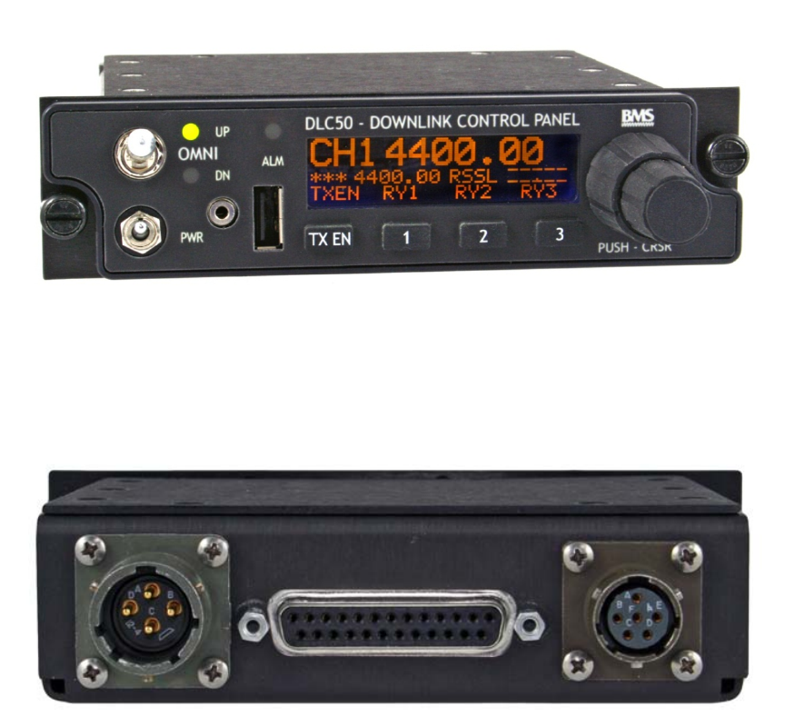
6.1 Operating the Transmitter with the DLC50 Control Panel
The HC4 is designed for standard operation via a BMS DLC50 Control Panel. After wiring the transmitter according to
the wiring diagram shown in the wiring and connection section the transmitter may be turned on via the power switch
(PWR) located on the front face of the DLC50 Control Panel. All transmit channel selection, receive channel control,
relay operation, and link configuration can be managed through the DLC50 menu structure and operated via the
simple dual ring control knob, Basic control panel commands used with the transmitter are shown in Figure 9 DLC50
Commands” on the following page. See “Figure 10 DLC50 Outline” for outline dimensions for the DLC50.
For a full description of control panel operation and custom configuration instructions, consult the DLC50 control panel
manual, BMS P/N 6051439500.
Figure 7 DLC50-A AVIONICS CONTROL PANEL (FRONT)
Figure 8 DLC50-A AVIONICS CONTROL PANEL (BACK)
Heli-Coder 4 Transmitter Operation Manual | Doc. No. 6051452100 Rev. B1
Broadcast Microwave Services, Inc. 15
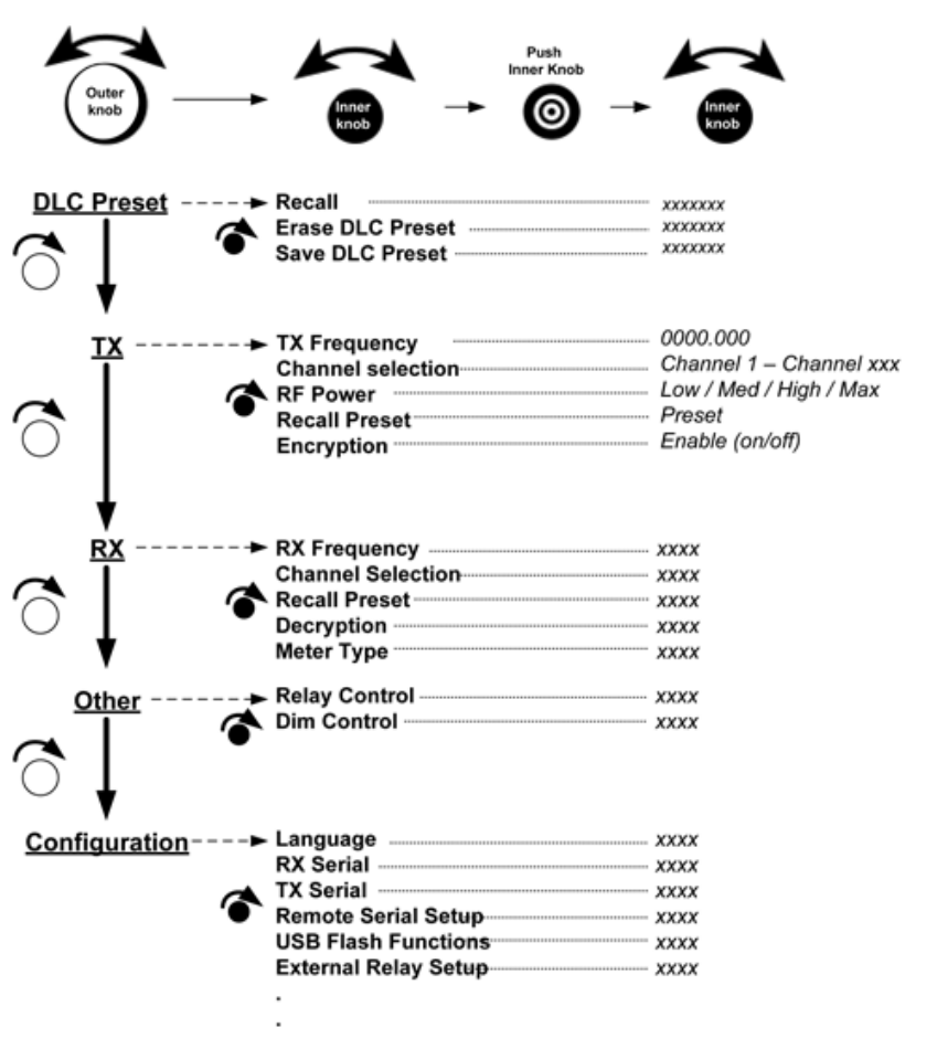
6.2 DLC50 Menu Structure
Figure 9 DLC50 Commands
Heli-Coder 4 Transmitter Operation Manual | Doc. No. 6051452100 Rev. B1
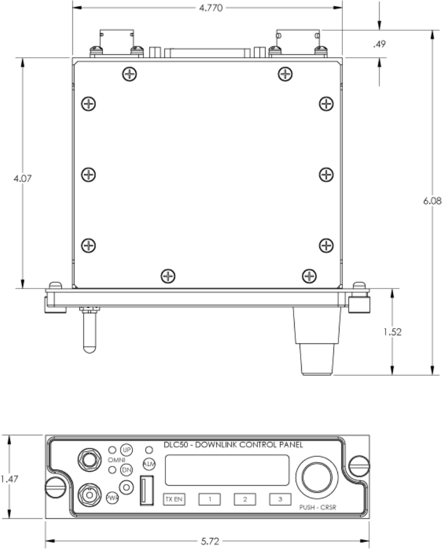
Broadcast Microwave Services, Inc. 16
Figure 10 DLC50 Outline

Heli-Coder 4 Transmitter Operation Manual | Doc. No. 6051452100 Rev. B1
Broadcast Microwave Services, Inc. 17
7 BMS Geo-Point™ System
7.1 Geo-Point System Description
The Geo-Point System provides a method for ground personnel to instantly know the range and direction to the center
point of live video they are viewing. Using information received from the camera sensor or on-board moving map, the
CVIII+ hand-held receiver/monitor displays both real-time video and an easy to interpret compass “rose” that shows
direction and distance information. Unlike other tactical systems that rely on external processors, Geo-Point direction
information is developed within the handheld receiver.
The Plus model CVIII contains an integral compass and GPS receiver. Geo-Point software looks for a special word in
the NMEA 0183 data stream known as Target Lat Long (TLL). Using the TLL data received from the aircraft the
receiver displays direction and distance to where the airborne camera is pointed.
Geo-Point is a proprietary feature of BMS products.
7.2 Enabling Geo-Point™
A GPS receiver is built into the HC4. J4 (COM PORT) pins 5 and 6 accept NMEA 0183 serial data containing the
“stare point” (SP) information from an external source (usually the camera or a moving map). This function is enabled
all the time. The GPS source will be external if there is valid NMEA data on pins 5/6. If an input on pins 5/6 is missing
or corrupt, the HC4 will revert to its internal GPS source to maintain sync with the tracking sites. Lacking the SP
information the Geo-Point enabled device will report the aircraft range and position.
The SP info must be added to the NMEA stream in the TLL word (Target Lat/Long) position. The RX site will track by
reading the aircraft position LAT/LONG from the NMEA stream while Geo-Pont enabled display, (e.g. a BMS CVIII+, or
CVIII+-HD) will use the TLL info to develop the range/distance report for the Geo-Point display overlay. BMS has
worked with several manufacturers to assure compatibility and support for the Geo-Point function. The addition of the
TLL word to the GPS message is supported by several interfacing equipment manufactures or may involve a simple
set-up process.
To learn more about how adoption of Geo-Point can benefit your agency contact the BMS.
Heli-Coder 4 Transmitter Operation Manual | Doc. No. 6051452100 Rev. B1
Broadcast Microwave Services, Inc. 18
8 SOFTWARE INSTALLATION
The DLC50 and HC4 both come completely loaded with the software required to operate the unit. However field
installation of software can easily be accomplished by the user in order to Update, Upgrade, or even reinstall the
system software. The process to install software on either the DLC50 or the HC4 involves loading a file via the USB
port on each device from a USB mass storage device. A USB memory stick will be recognized by both the DCL50 and
the HC4 and is a recommended device for providing the software update.
General Notes:
1. Control of the Installation process is accomplished via the control interface provided on the DLC50, however
the USB port on each unit must be used to perform the installation on that unit.
a. If you are loading an update into the DLC50, then the USB stick is inserted into the USB port of the
DLC50.
b. If you are loading an update into the HC4, then the USB stick is inserted into the USB port of the
HC4.
c. A device inserted into the USB port of the DLC50 WILL NOT be able to update the software in a
connected HC4.
2. Software files for installation MUST be stored in the root directory of the USB storage device or USB memory
stick.
3. The file type for the DLC50 is DLCsoft.hex
4. The file type for the HC4 is hc4_app.xxxxxxxxx.bin
Installation Procedure for the DLC50
1. Prior to starting the procedure, ensure the file for theDLC50 update is in the root level directory of the USB
device
2. Ensure that the DLC50 is powered ON.
3. Insert the USB device into the USB port on the front of the DLC50 control panel.
4. Wait 10 seconds (typically) for the system to recognize the file on the USB device.
5. Using the DLC50 front panel controls:
a. Rotate the OUTER knob to “Config.”
b. Rotate the INNER knob to “Config: USB Flash”.
c. Press the INNER Knob, or “OK” to select. The DLC50 will ask for confirmation.
d. Press the INNER knob, or “OK” to select “yes” to initiate the update.
Installation Procedure for the HC4
1. Prior to starting the procedure, ensure the file for the HC4 update is in the root level directory of the USB
device
2. Ensure that both the DLC50 and HC4 are powered ON and that the DLC50 is controlling the HC4.
3. Insert the USB device into the USB port of the HC4.
4. Wait 10 seconds (typically) for the system to recognize the file on the USB device.
5. Using the DLC50 front panel controls:
a. Rotate the OUTER knob to “TX”.
b. Rotate the INNER knob to “Software Update”.
c. Press the INNER Knob, or “OK” to select. The DLC50 will ask for confirmation.
d. Rotate INNER knob to highlight “yes”.
e. Press the INNER knob, or “OK” to select “yes” to initiate the update.

Heli-Coder 4 Transmitter Operation Manual | Doc. No. 6051452100 Rev. B1
Broadcast Microwave Services, Inc. 19
9 ACCESSORIES
Item Description Part Number
CT-A-MP Mounting Plate Mounting plate for transmitter 4414414000
HC4-CONN-KIT
Kit; Mating Connectors for HC4
Includes all PTO type connectors required for full HC4 installation.
Does not include USB, BNC, or N-Type connectors (all commonly
available).
7614521100
DLC50
Aviation control panel. Available in following configurations;
DLC50 Transmitter control
DLC50-A Transmitter and actuator control
DLC50-N Transmitter control, NVIS-B compliant
DLC50-AN Transmitter and actuator control, NVIS-B compliant
8714395002
8714395000
8714395003
8714395001
TAA-101
Skid mounted antenna actuator for microwave downlink.
Left Side Mount
Right Side Mount
870169302
870169304
GA-35 Garmin GPS antenna 120410017
Wiring Harness Contact BMS regarding custom system wiring harness Contact
Factory
Manual HC4 Operation and Installation Manual 6051452100
GCA-11 Directional Antenna Pod with belly mount Contact
Factory
Consult BMS for information about these products.
10 ADDITIONAL REFERENCES
The following documentation is recommended to further aid the installation of the HC4.
DLC50 Manual BMS # 6051439500
TAA-101 Actuator Manual (if used) BMS # 605169301
GA 35 Antenna Installation Instructions (if used) Garmin 190-00848-00
Heli-Coder 4 Transmitter Operation Manual | Doc. No. 6051452100 Rev. B1
Broadcast Microwave Services, Inc. 20
11 REGULATORY
11.1 Electromagnetic Compliance
CE marked in accordance with EU Low Voltage and EMC Directives
EN55022
EN55024
11.2 FCC
The HC4 is an intentional radiator and is authorized by the Federal Communications Commission (FCC) to comply
with the following parts of CFR 47 (grant pending);
Part 74
Part 90
11.3 Environmental Qualifications
The HC4 transmitter and DLC50 control panel have been designed to meet the following sections of RTCA DO-160G;
Section 4 Category A1 Temperature and Altitude
Section 5 Category B Temperature Variation
Section 6 Category A Humidity
Section 8 Category R,U2, (8.8.3) Vibration
Section 16 Category B, Designation I Power Input
Section 17 Category A Voltage Spike
Section 20.4 Radio Susceptibility - Conducted
Section 20.5 Radio Susceptibility - Radiated
Section 25 Electrostatic Discharge (ESD)

Heli-Coder 4 Transmitter Operation Manual | Doc. No. 6051452100 Rev. B1
Broadcast Microwave Services, Inc. 21
12 PREVENTIVE MAINTENANCE
In order to ensure system longevity it is highly recommended that the following preventive maintenance procedures be
done at the appropriate time.
12.1 Maintenance Schedule
Procedure Yearly Quarterly Monthly Prior Each Use
Inspect Mounting Hardware
Inspect Wiring (connection, chafing)
Inspect control and RF cables
Inspect TAA-101 Antenna Actuator
12.2 Maintenance Procedures
There are no required maintenance procedures for the HC4.
Include the following with preflight inspection:
Inspect mounting hardware to ensure all components are secure.
Inspect cables and connections.
12.3 Spare Parts
The HC4 has no user replaceable parts. Contact BMS for all service and repair inquiries. Factory contact information
is provided in section 21”REPAIR SERVICE AND WARRANTY”
Note: Any attempts to service individual components may void the warranty.
13 REPAIR SERVICE AND WARRANTY
BMS warrants that, at time of delivery, this product will be free from defects in materials and workmanship, provided
the equipment or system is installed, operated and maintained in accordance with the Operation and Maintenance
manual or such other BMS documentation as may be applicable. Any such defect reported to BMS within two years,
BMS will take reasonable and prompt action to repair or replace such equipment.
Should any of the components be defective, please contact BMS immediately. Please have the following information
available so we can best serve you.
Customer Name
Contract Number
BMS Model Number
Serial Number
Detailed Description of Problem
Name of Contact Person.
Contact Information such as phone number and/or email address.
Return Information
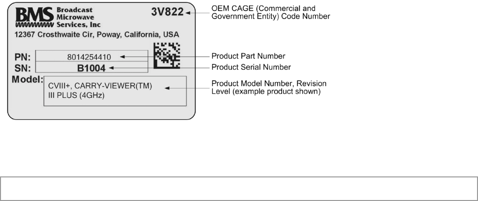
Much of this information can be found on the product label found on the component.
Heli-Coder 4 Transmitter Operation Manual | Doc. No. 6051452100 Rev. B1
Broadcast Microwave Services, Inc. 22
Figure 11 Product Label
Defective components under BMS warranty will be repaired/replaced promptly at the discretion of BMS. Items no
longer under warranty will require a PO before repairs can proceed.
NOTE: All goods returned for service require an RMA #. Any goods received without an RMA# may not be processed
in a timely manner. Please contact BMS for an RMA#.
13.1 Customer Service
Broadcast Microwave Services, Inc.
12367 Crosthwaite Circle, Dock 10 • Poway, CA 92064 • U.S.A.
Tel: +1-858-391-3050 • Toll Free (U.S.): 800-669-9667 • Fax: +1-858-391-3049
Website: www.bms-inc.com • E-mail: sales@bms-inc.com
Broadcast Microwave Services Europe
Schwalbacher Str. 12 • 65321 Heidenrod • Germany
Tel: +49-6124-72 39-00 • Fax: +49-6124-72 39-29
Website: www.bms-inc.com • E-mail: saleseurope@bms-inc.com

Heli-Coder 4 Transmitter Operation Manual | Doc. No. 6051452100 Rev. B1
Broadcast Microwave Services, Inc. 23
14 GLOSSARY
Analog Transmission Frequency Modulated (FM) method of sending information with radio waves.
An older, dependable method of transmission. (See Digital Transmission)
Antenna Actuator The mechanism which deploys or retracts the antenna radio operation or for
landing and take-off.
ASI: Asynchronous Serial
Interface.
Transmission standard used to connect video delivery equipment within a
cable, satellite or terrestrial plant.
BNC Connector The Bayonet Neill-Concelman connector is a type of RF connector used for
terminating coaxial cable. (See TNC connector)
COFDM: Coded Orthogonal
Frequency Division Multiplex
A digital modulation method that divides a single digital signal across multiple
(1000+) signal carriers simultaneously. BMS Coder II family products use
COFDM digital modulation.
Composite Video The format of an analog television (picture only) signal before it is combined
with a sound signal and modulated onto an RF carrier.
CVIII Carry-Viewer™ III Handheld Receiver Microwave downlink receiver with color
monitor
CVIII+ Carry-Viewer™ III+ (includes Geo-Point) Handheld Receiver Microwave
downlink receiver with color monitor
Data Wayside The data side channel on a microwave downlink
dB: Decibel A unit for expressing the ratio of two amounts of electric or acoustic signal
power equal to 10 times the common logarithm of this ratio.
dBm A unit for expressing the power ratio in decibel (dB) of the measured power
referenced to one milliwatt (mW).
Digital Transmission Digitally Modulated (COFDM and others) method of sending information with
radio waves. Newer more reliable method of transmission. (See Analog
Transmission)
Directional Antenna The final transmit element of a microwave system that radiates the signal one
direction, in a directed or focused narrow beam. This requires aiming of the
antenna toward the receive site.
DVB-T: Digital Video
Broadcasting-Terrestrial
An international digital television (DTV) standard that defines digital COFDM
modulation using MPEG2 compression.
DO-160 RTSC standard; Environmental Conditions and Test Procedures for Airborne
Equipment
Downlink Microwave transmission from air to ground
Geo-Point BMS Proprietary direction and ranging system
GPS: Global Positioning
System
A navigational system using satellite signals to fix the location of a receiver on
or above the earth’s surface
MPEG-2 A compression standard for digital video, audio, and data
H.264 A compression standard for digital video, audio, and data conforming to
MPEG-4, Section 10 AVC (Advanced Compression Standard)
HD-SDI High Definition Serial Digital Interface - A digitized video format for high
definition video
KLV Key Length Value. A method of encoding data into video streams. Defined in
standard SMPTE 336M-2007
Multipath The radio wave propagation phenomenon that results in the transmitted signals
ft. reaching the receiving antenna by two or more paths. This condition is not
desirable and usually results in signal fading and interference.

Heli-Coder 4 Transmitter Operation Manual | Doc. No. 6051452100 Rev. B1
Broadcast Microwave Services, Inc. 24
NMEA 0183 National Marine Electronics Association electrical and
data standard for communication between systems
NTSC The standard analog television system in use in the United States Analog
television encodes television picture information as an analog signal, that is, by
varying the voltages and/or frequencies of the signal.
Omni-Directional Antenna The final transmit element of the microwave system that radiates the signal
approximately equally throughout a 360 degree circle. Does not require aiming
of the antenna.
PAL phase-alternating line A color encoding used in broadcast television systems in large parts of the
world.
RF: Radio Frequency That portion of the Electromagnetic Spectrum that is used for radio and
television transmission.
SDI: Serial Digital Interface Serial Digital Interface - A digitized video format for standard definition
Stand-by The condition of an RF system where all but the transmit circuits are energized.
In this status the system may be switched into transmit mode instantaneously.
(See Transmit)
Stare-Point (SP) Stare-Point or SP refers to the center of a video camera picture
Symbology System of defined symbols
TLL Target Latitude Longitude
TNC Connector Threaded version of the BNC connector (See BNC connector)
Transmit The condition of an RF system where it is sending out signal. (See Stand-by)
Heli-Coder 4 Transmitter Operation Manual | Doc. No. 6051452100 Rev. B1
Broadcast Microwave Services, Inc. 25
15 CONNECTION AND WIRING DIAGRAMS
This section contains system and hook-up wiring diagrams.
Heli-Coder 4 Transmitter Operation Manual | Doc. No. 6051452100 Rev. B1
Broadcast Microwave Services, Inc. 26
Figure 12 Typical airborne installation diagram (without TAA-101 Antenna Actuator)
Heli-Coder 4 Transmitter Operation Manual | Doc. No. 6051452100 Rev. B1
Broadcast Microwave Services, Inc. 27
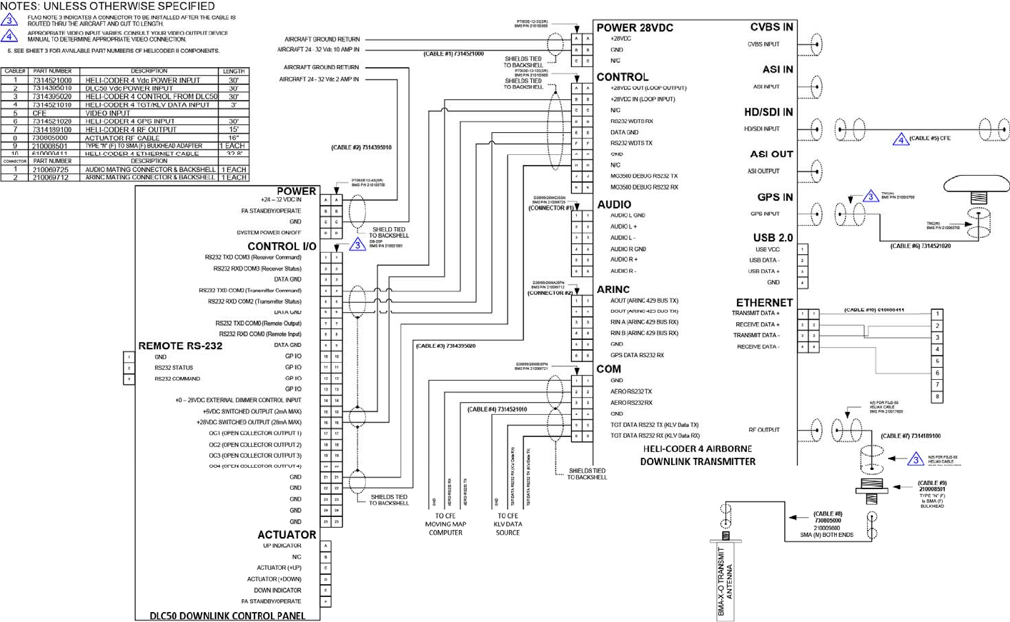
Figure 13 Wire Hook-Up Diagram for HC4 System (without TAA-101 Antenna Actuator)
Heli-Coder 4 Transmitter Operation Manual | Doc. No. 6051452100 Rev. B1
Broadcast Microwave Services, Inc. 28
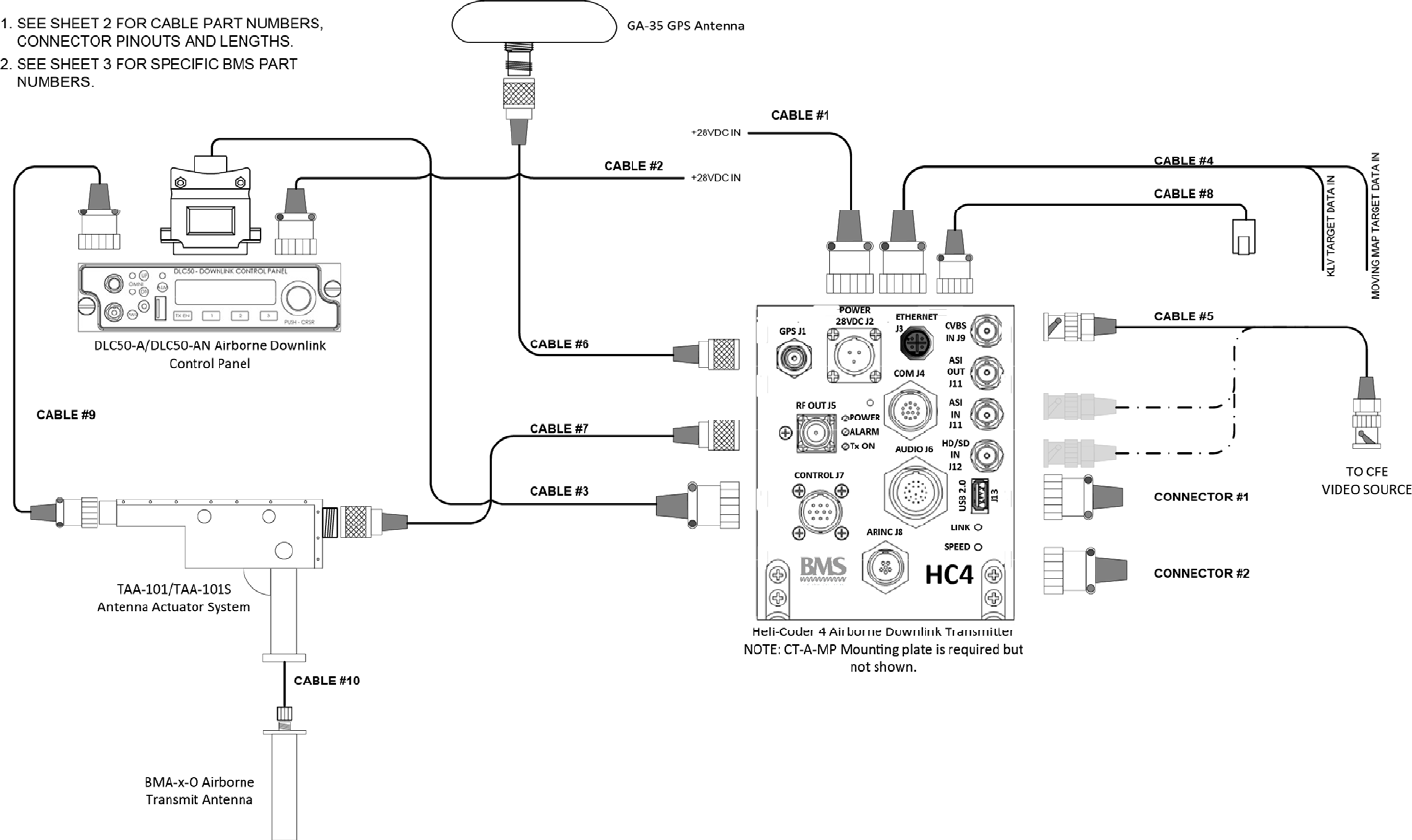
Figure 14 Typical airborne installation diagram (including TAA-101 Antenna Actuator)
Heli-Coder 4 Transmitter Operation Manual | Doc. No. 6051452100 Rev. B1
Broadcast Microwave Services, Inc. 29
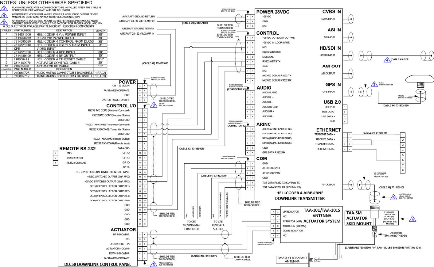
Figure 15 Wire Hook-Up Diagram for HC4 System (including TAA-101 Antenna Actuator)
Heli-Coder 4 Transmitter Operation Manual | Doc. No. 6051452100 Rev. B1
Broadcast Microwave Services, Inc. 30
16 COFDM Characteristics
The main COFDM modulation parameters are:
Number of sub-carriers (about 2000 for DVB-T)
Guard interval (GI) duration between COFDM symbols
Constellation scheme used for individual sub-carrier modulation
Data redundancy code rate used for error correction
The transmission robustness depends on constellation and code rate.
The following table gives the useful transmission bit rate for each COFDM mode. It also specifies the Carrier-to-Noise operation limit in the case of a perfect
line-of-sight (Gaussian) channel and in the case of a typical multipath terrestrial (Rayleigh) channel.
Constellation
Code
Rate Useful Bitrate (Mb/s) C/N for perfect
channel (dB) C/N for typical
channel (dB)
GI=1/4 GI=1/8 GI=1/16 GI=1/32
QPSK
1/2 4,98 5,53 5,85 6,03 3.1 5.4
2/3 6,64 7,37 7,81 8,04 4.9 8.4
3/4 7,46 8,29 8,78 9,05 5.9 10.7
5/6 8,29 9,22 9,76 10,05 6.9 13.1
7/8 8,71 9,68 10,25 10,56 7.7 16.3
16-QAM
1/2 9,95 11,06 11,71 12,06 8.8 11.2
2/3 13,27 14,75 15,61 16,09 11.1 14.2
3/4 14,93 16,59 17,56 17,10 12.5 16.7
5/6 16,59 18,43 19,52 20,11 13.5 19.3
7/8 17,42 19,35 20,49 21,11 13.9 22.8
64-QAM
1/2 14,93 16,59 17,56 18,10 14.4 16.0
2/3 19,91 22,12 23,42 24,13 16.5 19.3
3/4 22,39 24,88 26,35 27,14 18.0 21.7
5/6 24,88 27,65 29,27 30,16 19.3 25.3
7/8 26,13 29,03 30,74 31,67 20.1 27.9
Notice that a low code rate (high data redundancy) is necessary to insure a good efficiency in a multipath
environment.

Heli-Coder 4 Transmitter Operation Manual | Doc. No. 6051452100 Rev. B1
Broadcast Microwave Services, Inc. 31
The guard interval determines the maximum echoes length dispersion that the system can tolerate. From this figure, we can estimate the maximum
transmission range that the system might offer for a typical terrestrial channel (with adequate RF power).
The following table summarizes the results of the 4 possible guard interval values:
Guard Interval
Ratio Guard Interval
Duration (us) Maximum echoes
dispersion (km) Maximum transmission
distance (km)
1/32 7 2.1 2-6
1/16 14 4.2 4-12
1/8 28 8.4 8-24
1/4 56 16.8 16-48
Transmission distances can be increased when using directional antennas, but signal break-ups can still
occur if long echoes enter the receiving antenna beam width.
END