Broadcast Microwave Services HCII-9 6 GHz Power Amplifier User Manual 6GHz Power Amplifier Manual
Broadcast Microwave Services Inc 6 GHz Power Amplifier 6GHz Power Amplifier Manual
user manual
Broadcast Microwave Services, Inc. – 12367 Crosthwaite Circle – Poway, CA 92064 1
Phone: 800-669-9667, 1-858-391-3050 - Fax: 1-858-391-3049
Email: support@bms-inc.com Web: www.bms-inc.com
6GHz / 4W Power Amplifier
User Manual
(BPA-5CC-9)
Specifications are subject to change without prior notice.
This document contains confidential information and is intended for customer use only.
It cannot be duplicated without prior authorization from BMS.

Broadcast Microwave Services, Inc. – 12367 Crosthwaite Circle – Poway, CA 92064 2
Phone: 800-669-9667, 1-858-391-3050 - Fax: 1-858-391-3049
Email: support@bms-inc.com Web: www.bms-inc.com
WARNING!
RF RADIATION EXPOSURE HAZARD
This warning is provided by Broadcast Microwave Services (BMS) Inc. for safety purpose. The following information help
to reduce the risk of RF exposure hazard.
FCC Limit of RF Exposure
According to Federal Communication Commission (FCC), the Maximum Permissible Exposure (MPE) for FR radiation
has been set to 1.0 mW/cm2 for the 6 GHz Power Amplifier with maximum 4 Watt output power (OET Bulletin 65).
The 6 GHz Power Amplifier (PA) may ba a part of a non-broadcast transmitter and without an antenna it will not create
RF exposure (power density) exceeding the 1.0 mW/cm2 FCC limit.
However a high-gain antenna such as a parabolic dish will greatly enhance the 6 GHz PA output power density beyond
the MPE limit of 1.0 mW/cm2.
In this situation a minimum distance from the antenna needs to be calculated in order to keep the MPE always below
the safety limit. The calculation has been done for 6 GHz PA based on the formula mentioned in OET Bulletin 56.
The calculations have been done for different commonly used antenna in the BAS and Public Safety/ Law enforcement
applications.
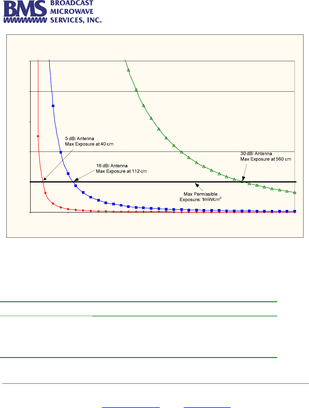
Figure 1 shows the plot of the minimum exposure distance for 5dBi, 16dBi, and 30dBi antennas. The 6 GHz PA
transmits the maximum power of 4 Watt. The minimum exposure distances are found from the cross points of the
exposure graphs (for various antennas) with the line of maximum permissible exposure (i.e. 1mW/cm2). Notice that the
numbers in Figure 1 predict the worse case scenario, which is straight in front of the antenna (exposing to the antenna
main-lobe). Obviously the side-lobe exposures are well below these numbers as the radiation intensity dramatically
reduces on the side lobes. The antenna used for this transmitter must not be co-located or operating in conjunction
with any other antenna or transmitter.
Broadcast Microwave Services, Inc. – 12367 Crosthwaite Circle – Poway, CA 92064 3
Phone: 800-669-9667, 1-858-391-3050 - Fax: 1-858-391-3049
Email: support@bms-inc.com Web: www.bms-inc.com
Estimated RF Exposure for 4 W att 6GHz Pow er Amplifie r
0.0
1.0
2.0
3.0
4.0
5.0
0 100 200 300 400 500 600 700
Distance , cm
Power Density, mW/cm^2
Figure 1
Summary
In order the keep the RF exposure within the FCC limit, it is necessary to maintain the safe distance from the antenna.
The results shown in Figures 1 can be summarized in the following table:
Antenna Gain (dBi) Minimum permissible distance from antenna (cm)
5
16
30
40
112
560
Notice the above table indicates worst-case situation (straight in front of the antenna).
Broadcast Microwave Services, Inc. – 12367 Crosthwaite Circle – Poway, CA 92064 4
Phone: 800-669-9667, 1-858-391-3050 - Fax: 1-858-391-3049
Email: support@bms-inc.com Web: www.bms-inc.com
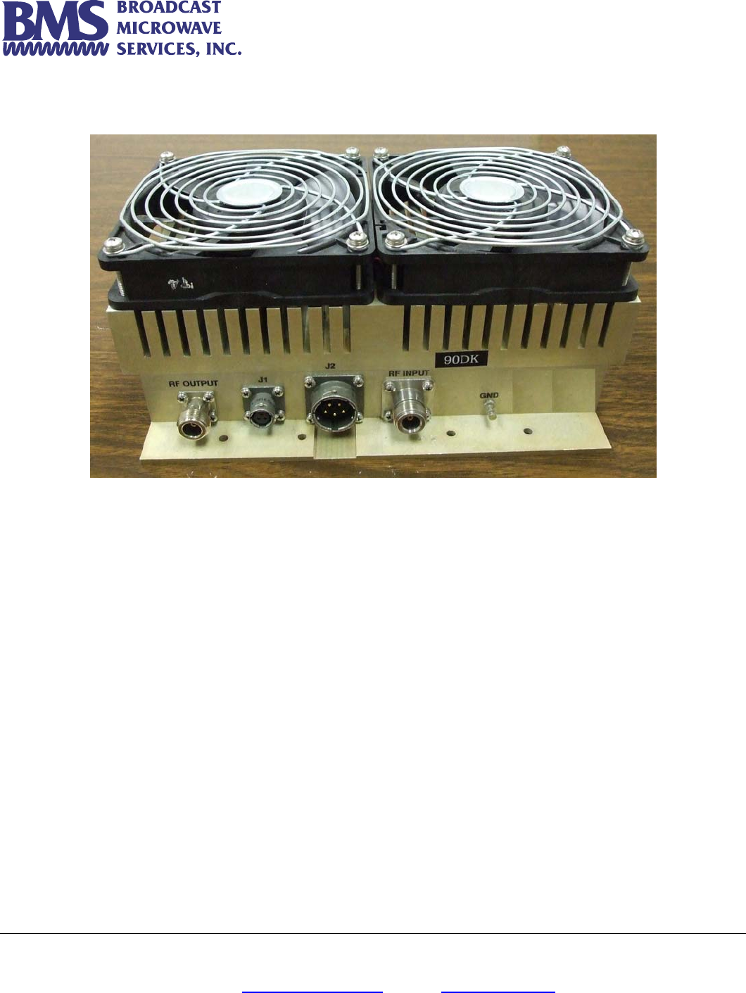
LINEAR POWER AMPLIFIER (BPA-5CC-9)
BPA-5CC-9 is a linear power amplifier with 4 watt maximum RF power and operating at 6.425 –
6.525 GHz). This power amplifier is used for increasing the transmitting range by boosting the
6GHz transmitter power to maximum 4 Watts.
Application
Portable 6GHz COFDM transmitters such as 6GHz Carry-Coder II, are used behind the camera in
Electronic News Gathering (ENG). These transmitters are only capable to provide a medium RF
power (e.g. 250mW). This seriously limits the distance between the event site and the TV relay
station. To extend the transmission range, an external amplifier is needed to boost the transmitter
power in order to compensate the path loss and ensure the acceptable Received Signal Level
(RSL) at the destination. The BPA-5CC-9 will increase the RF power to the maximum 4W, without
adding spurious and distortions to the transmitter output. The output of the power amplifier is
directly connected to the 6 GHz transmitting antenna.
Figure 1 BPA-5CC-9 Linear Power Amplifier
Broadcast Microwave Services, Inc. – 12367 Crosthwaite Circle – Poway, CA 92064 5
Phone: 800-669-9667, 1-858-391-3050 - Fax: 1-858-391-3049
Email: support@bms-inc.com Web: www.bms-inc.com
Specification:
Ch
Frequency 6.425 – 6.525 GHz
Output Power 4 Watt max.
Input Voltage 28 VDC
Input Current 7.3 Amp
Input RF Power 16 mW (12 dBm) max.
Gain @ 12 dBm input 25 dB
Gain Flatness ± 0.5 dB Over 50 MHz
Gain vs. Temperature ± 1 dB Over Temperature
Operating Temperature -20° to +50°C
Storage Temperature 40° to +90°C
Dimensions 9.5” x 5” x 3”
Weight 5 lbs
RF Input Connector Type “N”
RF Output Connector Type “N” Isolator Protected
CONTACT INFORMATION
Broadcast Microwave Services, Inc.
Phone: 1.858.391.3050
Fax: 1.858.391.3049
Shipping address: 12367 Crosthwaite Circle
Poway, CA 92064
Website: http://www.bms-inc.com
Email: support@bms-inc.com
sales@bms-inc.com
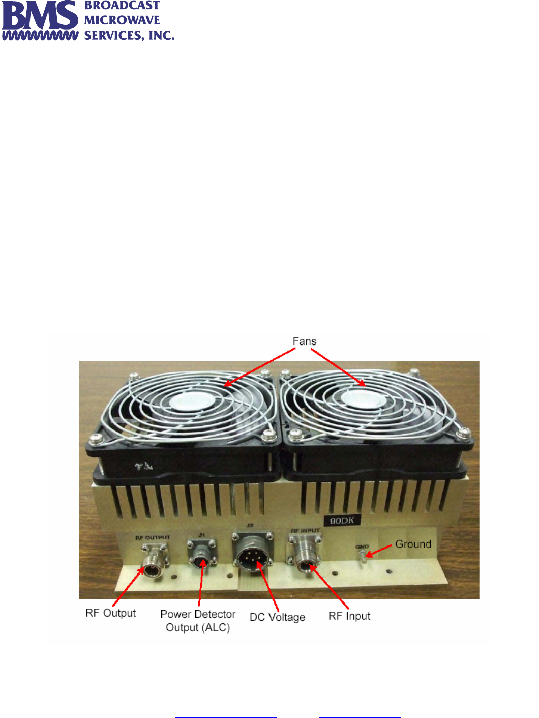
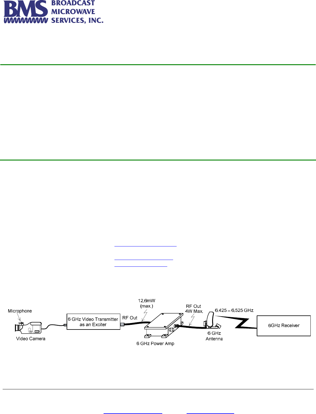
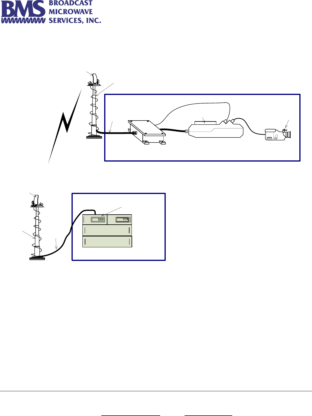
Typical application of the 6GHz Power Amplifier is shown in Figure 2.
Figure 2 Typical application of the 6GHz Power Amplifier
Broadcast Microwave Services, Inc. – 12367 Crosthwaite Circle – Poway, CA 92064 6
Phone: 800-669-9667, 1-858-391-3050 - Fax: 1-858-391-3049
Email: support@bms-inc.com Web: www.bms-inc.com
The diagram of Figure 2 simply shows the connections, not indicating a practical installation. A
more informative diagram is shown in Figure 3.
Microphone
Video Camera
6 GHz Power Amp
RF Out
RF Out
4W Max.
Optional Battery
6 GHz Carry-Coder II
Transmitter Site
The antenna mast is
located on the roof of the
vehicle
6GHz Decoder II
Coaxial
Cable
Power Supply
Control Unit
Receive Site
Coaxial
Cable
Antenna
Mast
Receiving
Antenna
Transmitting
Antenna
ALC Loop
Figure 3 Typical system of 6GHz Carry-Coder II with power amplifier
The output of the 6GHz power amplifier is directed to the transmitting antenna located on a mast.
The mast is positioned on the rooftop of a mobile vehicle.
The receiver antenna can also be located on a mast to result a better coverage over longer
distance.