Broadcast Microwave Services TCII-ODU-9 7 GHz Truck Coder II User Manual 7GHz TCII Manual 4 FCC
Broadcast Microwave Services Inc 7 GHz Truck Coder II 7GHz TCII Manual 4 FCC
user manual
Installation and Operations Manual
7GHz Truck Coder II
System
DOC# 6051419100X3 July 2006
Broadcast Microwave Services, Inc.
12367 Crosthwaite Circle
Poway, CA 92064
800-669-9667, 858-391-3050
858-391-3049 FAX
This Page Intentionally Left Blank

INTRODUCTION
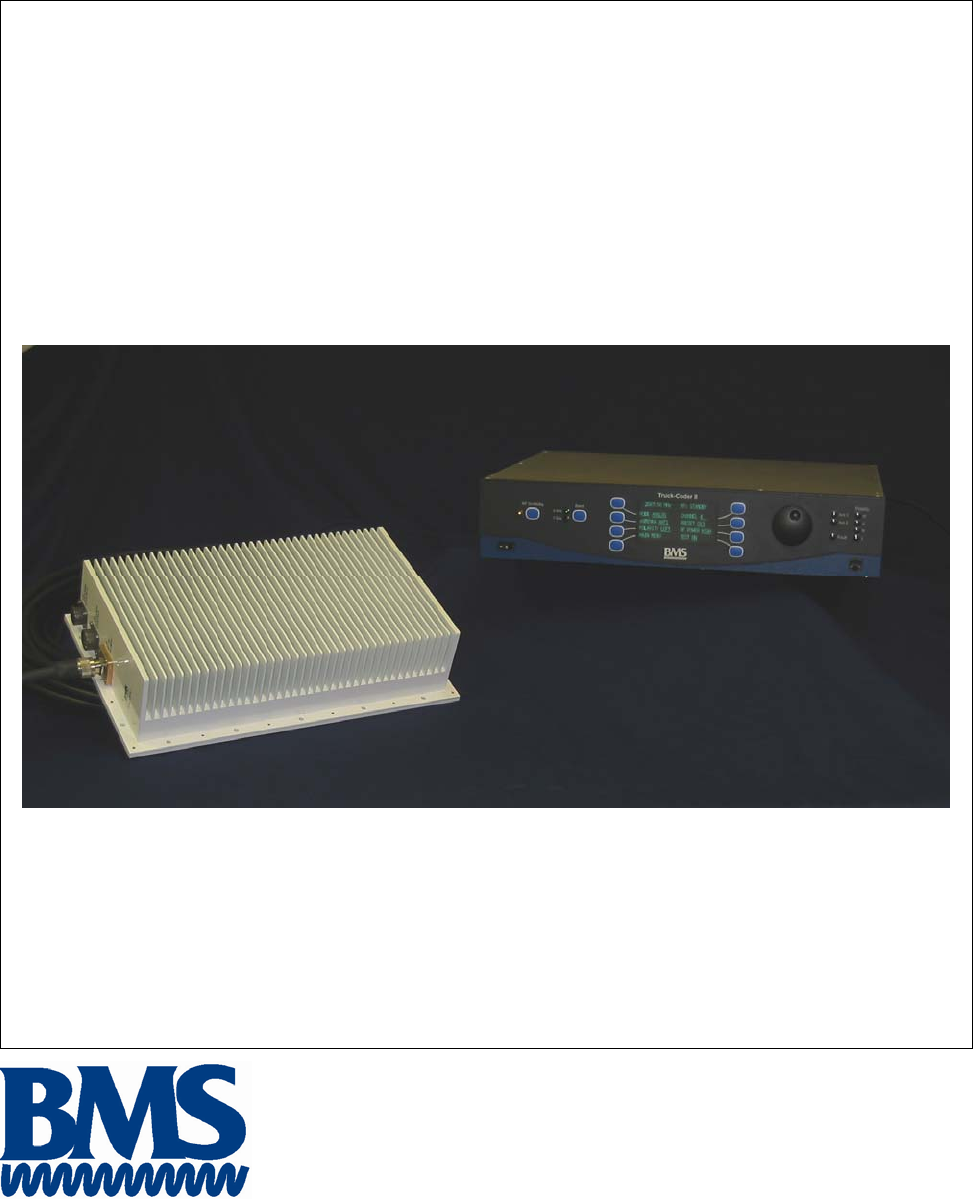
The BMS Truck-Coder II (TCII) is an ENG transmitter that operates in both digital (COFDM) and legacy
analog (FM) transmission modes. It features a DVB-T compliant (COFDM) modulator MPEG2 video
encoder. The system is designed to support both 12 MHz and 17 MHz BAS channel plans (in both Digital
and FM transmission modes). The two-unit system consists of an Indoor rack-mounted exciter Unit (IDU)
and an Outdoor mast-mounted RF Transmitter Unit (ODU). An optional second RF unit can be added to
support dual band operation. The system integrates support for mast mounted antenna relay, feed controls
and other accessories. The indoor unit provides support for multiple analog and video signal formats and
provides an industry standard 70MHz IF output.
The Truck-Coder II is designed to meet the rugged environmental needs of ENG news vehicles. It blends
our field proven technology with a rich feature set and the simple operation needed for ENG/OB
operations.
Applications:
• ENG News Vehicles
• Law Enforcement Command Posts
Key Features:
• Digital (COFDM) and Analog (FM) Transmission
• Ease of installation – a single coax cable interconnects the IDU and ODU
• Simple Set-up and Operation – menu driven user interface
• Up to 999 easily configurable user Presets (each capable of storing all system parameters)
• Front panel Ethernet Port simplifies firmware upgrades and supports web based management
• Fully configurable FM, COFDM and MPEG parameters (including PID’s) ensure product
compatibility
• Optional Dual Band Capability
This document provides instructions for the installation, operation and maintenance of the Truck Coder II
system.
Broadcast Microwave Services (BMS) is a leader in wireless digital microwave technology providing
innovative products for the television broadcast, video, telemetry and surveillance industries. A wholly
owned subsidiary of Cohu, Inc., BMS designs and manufactures a comprehensive line of microwave
communications equipment for broadcasting sports venues, law enforcement and military applications.
BMS also builds and integrates command and control centers to provide fully functioning, complex, end to
end digital systems.
For the latest product and system information please visit www.bms-inc.com.
Broadcast Microwave Services, Inc.
12367 Crosthwaite Circle
Poway, CA 92064
Tel: +1 (858) 391-3050
Toll free (US): 800-669-9667
Fax: +1 (858) 391-3049
Email:sales@bms-inc.com
Web: www.bms-inc.com
ii
This Page Intentionally Left Blank
iii
Table of Contents
INTRODUCTION........................................................................................................................................... i
SYSTEM DESCRIPTION ............................................................................................................................. 1
Overview.................................................................................................................................................... 1
Indoor Unit................................................................................................................................................. 2
Outdoor Unit .............................................................................................................................................. 4
Technical Specifications ............................................................................................................................ 5
UNPACKING ................................................................................................................................................ 9
Parts List .................................................................................................................................................... 9
Manuals ................................................................................................................................................. 9
Components ........................................................................................................................................... 9
Cables .................................................................................................................................................... 9
INSTALLATION......................................................................................................................................... 11
Equipment Installation ............................................................................................................................. 11
Installing the Indoor Unit (IDU).......................................................................................................... 15
Indoor Unit (IDU) Connections........................................................................................................... 17
Installing the Outdoor Unit (ODU)...................................................................................................... 18
OPERATION ............................................................................................................................................... 22
Initialization ............................................................................................................................................. 22
WARRANTY............................................................................................................................................... 25
Customer Service Information ................................................................................................................. 25
TROUBLE SHOOTING .............................................................................................................................. 27
Diagnostics............................................................................................................................................... 28
PIN OUTS................................................................................................................................................ 30
IDU ...................................................................................................................................................... 30
ODU .................................................................................................................................................... 32
US Broadcast Frequency Assignments......................................................................................................... 34
Coded Orthogonal Frequency Division Multiplex (COFDM) Modulation .................................................. 36
Glossary........................................................................................................................................................ 40
List of Figures
Figure 1 TCII System Overview .................................................................................................................... 1
Figure 2 TCII IDU (Indoor Unit) Block Diagram .......................................................................................... 2
Figure 3 TCII Outdoor Unit (ODU) Block Diagram...................................................................................... 4
iv
Figure 4 IDU Footprint................................................................................................................................. 13
Figure 5 ODU Footprint ............................................................................................................................... 14
Figure 6 TCII Indoor Unit ............................................................................................................................ 15
Figure 7 TCII Indoor Unit Rear Panel Connections ..................................................................................... 17
Figure 8 TCII Outdoor Unit.......................................................................................................................... 18
Figure 9 ODU Mounting Footprint .............................................................................................................. 19
Figure 10 ODU Mounting Orientation ......................................................................................................... 20
Figure 11 ODU Connections ........................................................................................................................ 21
Figure 34 The HOME Menu ........................................................................................................................ 22
Figure 36 Product Label ............................................................................................................................... 25
Figure 37 IDU REAR PANEL CONNECTORS.......................................................................................... 30
Figure 38 ODU CONNECTORS ................................................................................................................. 32
List of Tables
Table 1 General Specifications....................................................................................................................... 5
Table 2 Analog (FM)...................................................................................................................................... 6
Table 3 Digital (COFDM).............................................................................................................................. 6
Table 4 TCII Input/Output.............................................................................................................................. 7
Table 5 Component Mounting Requirement Reference ............................................................................... 11
Table 6 ODU Connections ........................................................................................................................... 21
Table 7 AUXILIARY INPUT PINOUTS .................................................................................................... 30
Table 8 SUMMARY ALARM PINOUTS ...................................................................................................30
Table 9 AUDIO 1 IN PINOUTS .................................................................................................................. 31
Table 10 AUDIO 2 IN PINOUTS ................................................................................................................ 31
Table 11 J1 EXTERNAL DATA IN ............................................................................................................ 32
Table 12 J2 EXTERNAL DC IN PIN OUTS (Optional) ............................................................................. 32
Table 13 J4 ANTENNA CONTROL PIN OUTS......................................................................................... 33
Table 14 ODU J5 EXTERNAL CONTROL PIN OUT................................................................................ 33
v
WARNING!
RF RADIATION EXPOSURE HAZARD
This warning is provided by Broadcast Microwave Services (BMS) Inc. for safety purpose. The
following information help to reduce the risk of RF exposure hazard.
FCC Limit of RF Exposure
According to Federal Communication Commission (FCC), the Maximum Permissible Exposure (MPE) for
FR radiation has been set to 1.0 mW/cm2 for the 7GHz Truck-Coder II equipment (OET Bulletin 65).
The 7GHz Truck-Coder II is a non-broadcast transmitter and without an antenna it will not create RF
exposure (power density) exceeding the 1.0 W/cm2 FCC limit.
However a high-gain antenna such as a parabolic dish will greatly enhance the Field-Coder II output power
density beyond the MPE limit of 1.0 mW/cm2.
In this situation a minimum distance from the antenna needs to be calculated in order to keep the MPE
always below the safety limit. The calculation has been done for Field-Coder II based on the formula
mentioned in OET Bulletin 56.
The calculations have been done for different commonly used antenna in Electronic New Gathering (ENG)
systems.
Transmission
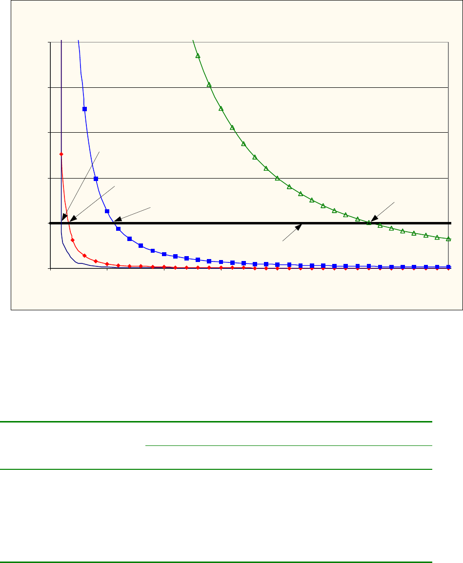
Figure 1 shows the plot of the minimum exposure distance for 0dBi, 5dBi, 16dBi, and 30dBi antennas. The
7GHz Truck-Coder II transmits the maximum power of 4 Watts. The minimum exposure distances are
found from the cross points of the exposure graphs (for various antennas) with the line of maximum
permissible exposure (i.e. 1 W/cm2). Notice that the numbers in Figure 1 predict the worse case scenario,
which is straight in front of the antenna (exposing to the antenna main-lobe). Obviously the side-lobe
exposures are well below these numbers as the radiation intensity dramatically reduces on the side lobes.
The antenna used for this transmitter must not be co-located or operating in conjunction with any other
antenna or transmitter.
Antenna Specifications
The antenna for Truck-Coder II is customer's furnished equipment. The customer has a choice of using, for
instance, a 0dBi Omni antenna or a 30dBi dish antenna. The plots of Figure 1 provide the exposure distance
for 0dBi and 5dBi Omni antennas as well as 16dBi and 30dBi dish antennas.
vi
Estimated RF Exposure for 7 GHz Truck-Coder II
0.0
1.0
2.0
3.0
4.0
5.0
0 100 200 300 400 500 600 700
Distance , cm
Power Density, mW/cm^2
Max Permissible
Exposure: 1mW/cm2
30 dBi Antenna
Max Exposure at 560 cm
0 dBi Antenna
Max Exposure at 20 cm
16 dBi Antenna
Max Exposure at 112 cm
5 dBi Antenna
Max Exposure at 35 cm
Figure 1
Summary
In order the keep the RF exposure within the FCC limit, it is necessary to maintain the safe distance from
the antenna. The results shown in Figures 1 can be summarized in the following table:
Minimum permissible distance from antenna (cm)
Antenna Gain
(dBi)
0 20
5 35
16 112
30 560
Notice the above table indicates worst-case situation (straight in front of the antenna).
1
SYSTEM DESCRIPTION
Overview
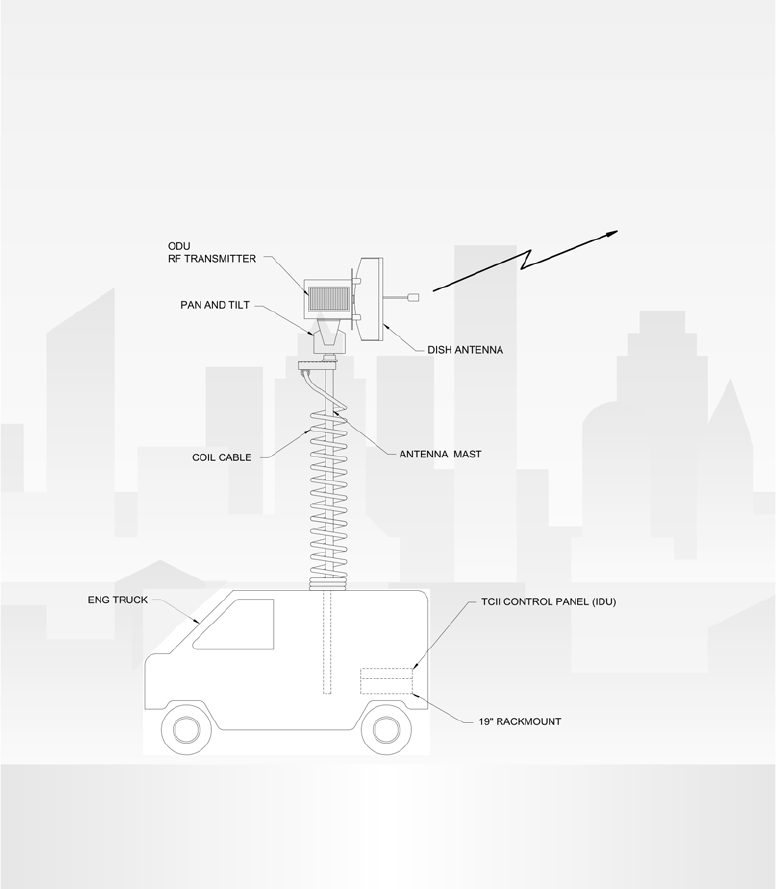
The Truck-Coder II (TCII) is an ENG transmitter that will operate in both Digital (COFDM) and Analog
(FM) modes. The system comprises of an indoor unit (Exciter) and a mast mounted outdoor unit (RF
transmitter).
Figure 1 TCII System Overview
The indoor unit is designed to be rack mounted within an ENG van. It is housed in a 2RU 19-inch rack
mount enclosure and powered from a conventional 120V AC source. The indoor unit contains full featured
DVB-T compliant Digital (COFDM) and Analog (FM) exciters and associated power supplies. The IDU
provides the necessary DC voltage to power the ODU.
2
To simplify installation, only a single coaxial cable is required to interconnect the IDU to the ODU; DC
power, 70MHz IF and telemetry signals are all multiplexed onto this single cable. The system also supports
legacy cable systems that feed DC power on separate conductors.
The indoor unit features a menu driven front panel display (vacuum fluorescent) that is used to configure
the equipment and monitor its performance. The system is also designed to support remote control by 3rd
party equipment using either web based or simple RS232 protocol.
The outdoor RF unit (ODU) is designed to be mounted outdoors adjacent to the antenna. The ODU
translates the 70MHz IF signal from the IDU (exciter) to the desired operating frequency and amplifies the
signal to the desired level. The RF unit employs automatic level control circuits that keep the system
operating optimally and eliminate the need for any user adjustments.
The ODU uses a common signal path for both Analog (FM) and digital (COFDM) operation. Performance
is automatically optimized for both methods. BMS transmitters feature superior COFDM performance that
is adequate to support split channel operation in a 12MHz channel (see BMS white paper).
The ODU provides signals to control an antenna relay and feed polarity. Additional contact closures are
also provided for user specific applications.
A more detailed description follows:
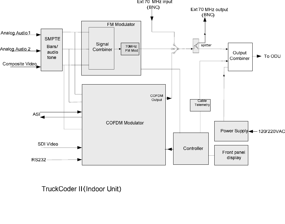
Indoor Unit
A simplified block diagram of the IDU is shown below:
Figure 2 TCII IDU (Indoor Unit) Block Diagram
3
The FM modulator is designed to accept analog audio and video inputs. Support for 2 audio channels is
provided via frequency programmable sub carriers that ride above the video signal The frequency deviation
is user configurable to support operation in either a 17 MHz or 12 MHz channel allowing Analog operation
to continue after the channel plan transition is complete. Analog transmission offers a more graceful
degradation in performance and might be preferred under certain conditions.
The Digital (COFDM) modulator also supports 2 analog audio and one analog video input but also supports
advanced digital interfaces (ASI, SDI) as well. The digital modulator includes an MPEG2 encoder and a
DVB-T compliant COFDM modulator. Both MPEG and COFDM parameters are fully configurable by the
system controller in support of optimum performance and compatibility with other vendors equipment. For
those users less familiar with detailed COFDM and MPEG settings, the equipment provides 3 preset
robustness settings (low, mid and high) that each optimize video performance at the expense of modulation
complexity. High robustness provides the lowest quality video but is able to operate in severely
compromised locations. Low robustness provides the best quality video but may require a clear line of sight
shot.
An integrated SMPTE color bar generator with programmable text overlay is included. The indoor unit
features a menu driven VFD front panel display. Two levels of user access are supported; Operator and
Engineer. Operator is designed for non-technical users and assumes that the equipment has been
preconfigured by a station engineer. Engineer has full access to all menus and the ability to set up the
equipment for a less qualified operator.
The system accommodates up to 999 user programmable presets. These can be uniquely named and
configured; each preset records all of the configurable variables within the system. Presets 1 thru 6 are
conveniently displayed on their own screen for quick and easy recall. All presets can be uniquely named
via the front panel menu system to simplify identification and can be recalled quickly to put the equipment
in a known state. Presets are an ideal mechanism for the station engineer to pre-configure the equipment for
simplified operation by a less skilled operator.
The system also features a front and rear panel ethernet interface that can be conveniently used to upload
new operating firmware into the unit. This interface supports high data transfer rates and simplifies the
firmware upgrade process. This equipment makes extensive use of FPGA (field programmable gate array)
and microprocessor controlled hardware. Ease of firmware upgrade helps ensure that the equipment is
always kept up to date.
The TCII also includes embedded web based management that can be accessed with any PC using a web
browser and connected to the front or rear panel Ethernet port. This interface supports all the front panel
programmable features as well as others such as the ability to configure channel plans, and download
preconfigured presets (duplicate equipment setups). The system can be controlled remotely via an RS232
control port as well; consult BMS for the protocol specification for this port.
4
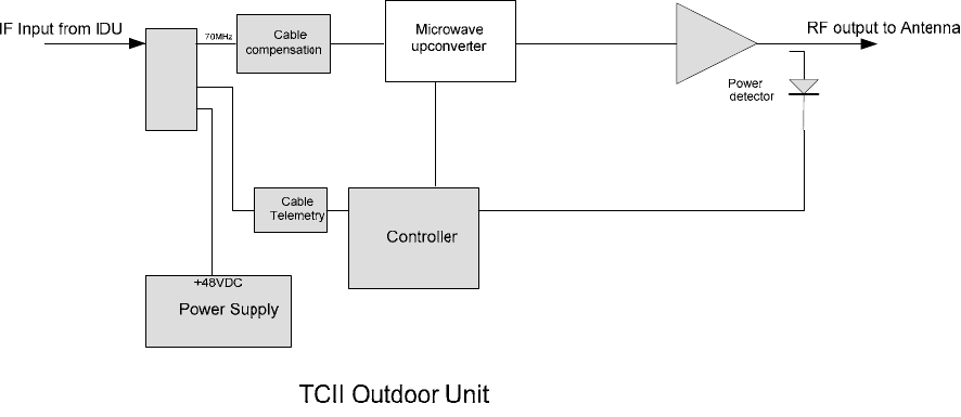
Outdoor Unit
A simplified block diagram of the ODU is shown below:
Figure 3 TCII Outdoor Unit (ODU) Block Diagram
The ODU is mounted outdoors and connected to the IDU by a single coaxial cable.
The ODU is in constant communication with the IDU via a telemetry channel that is frequency multiplexed
onto the single cable interface between the IDU and ODU. This channel is used to configure the ODU
(select frequency, power level etc) and also to monitor performance (PLL lock, temperature etc). A
microcontroller within the ODU handles this communication and controls the respective parts of the ODU.
The 70MHz input is first up-converted to the UHF band and then up-converted again to the desired
operating frequency. The signal is then amplified and fed to the antenna. A power detector at the
transmitter output helps ensure that the transmitter always operates most efficiently which is particularly
important when transmitting digital COFDM.
The ODU provides connector interfaces to support remote (mast mounted) antenna selection and antenna
feed polarity selection. Four additional contact closures are also provided for user specific applications.
These are controlled by corresponding inputs at the IDU.
A temperature sensor is included in the ODU and can be monitored on the IDU front panel. If the
equipment is operated in extremely hot temperatures the ODU will automatically back off the output power
to preserve operation and prevent damage to the unit.

5
Technical Specifications
Table 1 General Specifications
Indoor Unit (IDU) Outdoor Unit (ODU)
Size 17.5 x 14.9 x 3.5 in
(44.1 x 37.8 x 8.9 cm)
15.0 x 3.7 x 9.0 in
(38.1 x 22.9 x 9.2 cm)
Weight 11 lb (5 kg) 16.5 lb (7.5 kg)
Oper Altitude 15,000 ft 15,000 ft
Operating Temp -20 - +55º C -20 - +55º C
Stor. Temp -30 - +70º C -40 - +80º C
Relative Humidity 98% NC 100%
Power Req 105-260 VAC 50/60 Hz 48 VDC (supplied by IDU)
Ventilation Requirements Fan inlet and outlets must have no
obstruction
Fins must be oriented vertically on
antenna mast
Specification
Frequency 6.4 – 7.2 GHz
(Pre-programmed with US 12 MHz and 17MHz BAS channel plans
including offsets)
Tuning Step Size 250KHz
Frequency Stability +/- 5ppm max
Power Consumption 200W max
Recommended IDU-ODU Cable 100ft max
50 or 75 Ω cable (selectable)
Average Output Power
(6.4 – 7.2 GHz) FM COFDM
4 W (typical) 4 W (typical)

6
Table 2 Analog (FM)
Feature Spec
Video
Video Deviation (MHz) 4.0MHz pk /17 MHz Ch
3.5MHz pk /12 MHz Ch
Video Pre-Emphasis 405
(Per CCIR Recommendation)
VSNR (@12 MHz) 2 GHz 63 dB Typical (60 dB min.)
7 GHz 63 dB Typical (61 dB min)
Audio
Audio Sub-Carriers (2) Frequency (Programmable)
#1 4.83, 5.5, 5.8, 6.2, 6.8 MHz
#2 5.5, 5.8, 6.2, 6.8, 7.5 MHz
Audio Deviation ± 75kHz pk
Audio Pre-Emphasis 75 µS
Audio Distortion 1% max
Table 3 Digital (COFDM)
Feature Spec
Bandwidth 6, 7, 8 MHz Selectable
Constellation QPSK, 16 QAM, 64 QAM, Selectable
Guard 1/4, 1/8, 1/16, 1/32 Selectable
Code Rate 1/2, 2/3, 3/4, 5/6, 7/8 Selectable
Scrambler Proprietary 6 digit PIN code
MPEG – 2 4:2:0 SP@ML 1.5 – 15 Mb/s, 0.1 Mb/s Resolution
MPEG – 2 4:2:2 SP@ML 1.5 – 32 Mb/s, 0.1 Mb/s Resolution
GOP Structure I/IP/IBBP/422IBBP Variable
GOP Length 6/12/18/24 Selectable
Audio Sampling Rates 32, 64, 128, or 192 kb/s per Channel
Audio, Video, PCR PID User programmable

7
Table 4 TCII Input/Output
I/O Format
IF OUT (to ODU) 70 MHz IF Output with Control & Power
(selectable 50 or 75 ohms)
IF IN 70 MHz (0dBm, 75 Ω)
Aux. IF OUT 70 MHz (0dBm, 75 Ω, BNC-f)
ASI IN 75 Ω (HD Capable)
ASI OUT Encoder Output 75 Ω (BNC-f)
Digital Video IN SDI w/Embedded Audio
(SMPTE 259C CCIR 601)
Aux Inputs (4) General purpose inputs that control respective Form
‘C’ contact closures available at the ODU.
Summary Alarm Form ‘C’ Contact Closure (Rated 1A Max )
External Control 1
(Remote Control Of TCII)
Ethernet 10/100 bT
Digital (COFDM) Analog (FM)
Audio Inputs (2)
Impedance 600 ohm Bal
Level +0 dB nom
menu adj atten +4 to -9dB,
in 1dB steps
+9dBm
(Factory Set)
Composite Video Input
Level 1V p-p
Return loss 26dB min
Impedance 75 ohms unbal
YUV Video Input (Optional) Optional Not Available
RS232 (general purpose data channel to CRS-
DCII)
User selectable
1200, 4800, 9600 baud
Not operational
1 Consult Factory For Protocols
8
This Page Intentionally Left Blank

9
UNPACKING
No special instruction is required for removing the items from the packaging other than to open the box
with care as to not damage any of the contents.
Parts List
Manuals
Item Part Number Quantity
TRUCK-CODER II INSTALLATION AND
OPERATION MANUAL
6051419100 1
Components
Item Part Number Quantity
Indoor Unit (IDU) 8014191000 1
Outdoor Unit (ODU) 8014192700 1
Installation Kit 7614191020 1
Cables
The versatile design of the TCII makes it suitable for many different applications. Depending on the needs
of the ENG, there is a great variety of cable configurations. The table below provides a list of all the cables
that the TCII can accommodate and along with the BMS part numbers. The specific cable set for any
application is defined when an order is placed. Please refer to the packing list and/or the original sale order
for the specific cables included with your TCII System.
Cable Recommended
Cable
P/N
Length End
Connector
P/N
70 MHz/ 48 VDC (to ODU) TIMES SF-214
(STANDARD)
100 ft ( 30.5 m) 210009800
70 MHz/ 48 VDC triax (to
ODU) Belden 8232 100 ft ( 30.5 m) 210071813
70 MHz IN 100 ft ( 30.5 m)
70 MHz OUT 100 ft ( 30.5 m)
SDI IN w/ AUDIO 100 ft ( 30.5 m)
ASI IN 100 ft ( 30.5 m)
ASI OUT 100 ft ( 30.5 m)
VIDEO IN 100 ft ( 30.5 m)
VIDEO OUT 100 ft ( 30.5 m)
Y,U, V input
600001300
100 ft ( 30.5 m)
210015200
AUDIO 1 IN 100 ft ( 30.5 m)
AUDIO 2 IN 600000100 100 ft ( 30.5 m) 210019300
RS-232 DCE 100 ft ( 30.5 m)
RS-232 CONTROL 100 ft ( 30.5 m)
RS-232 AUX DATA
Custom
100 ft ( 30.5 m)
210022000
10
This Page Intentionally Left Blank

11
INSTALLATION
NOTE:
The TCII equipment installation should only be performed by qualified technicians in compliance with
safety regulations and accepted industry practices.
Equipment Installation
The following equipment will need to be installed:
Indoor Unit (IDU)
Outdoor Unit (ODU)
Please refer to component footprint drawings listed in Table 5 to aid installation.
Table 5 Component Mounting Requirement Reference
Component Footprint
Indoor Unit (IDU) Figure 4
Outdoor Unit (ODU) Figure 5
12
This Page Intentionally Left Blank
13
19.0 in
48.3 cm
3.5 in
(8.9 cm)
14.9
17.5 in
44.1 cm
Do Not Block Fan
Inlets or Outlets
Do Not Block Fan
Inlets or Outlets
Figure 4 IDU Footprint
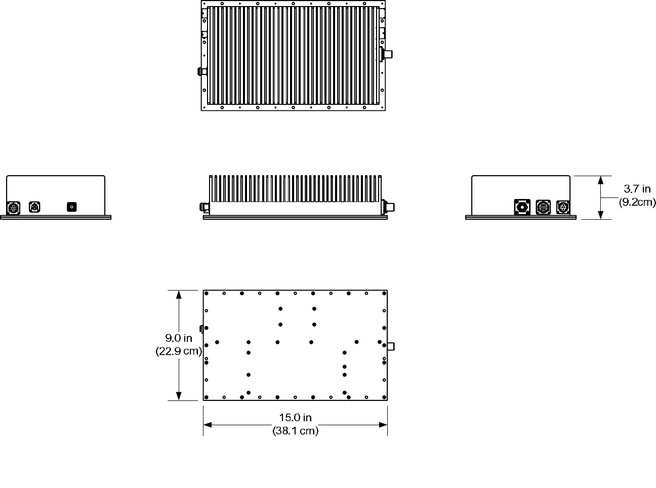
14
Figure 5 ODU Footprint
15
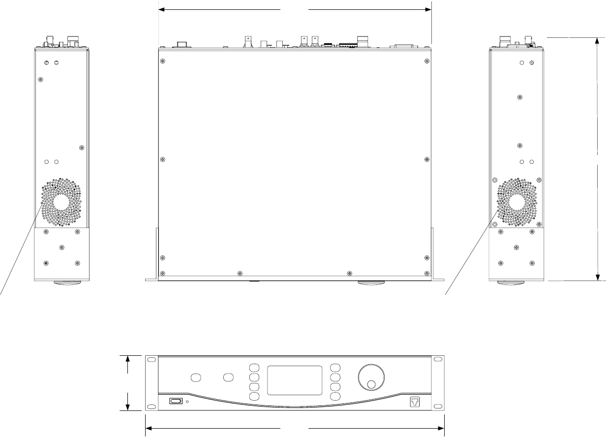
Installing the Indoor Unit (IDU)
Figure 6 TCII Indoor Unit
To install the Truck-Coder II Indoor unit:
The TCII Indoor unit is designed to fit in a standard 19” rack using either permanent shelf or rails to
support the IDU. A mounting kit (BMS P/N 7614191020) is included if needed.
Select a location to mount the unit. There needs to be enough space around the unit to allow for proper
ventilation and access to connections.
Warning:
Failure to ensure proper ventilation could cause the system to overheat resulting in system failure and
possible damage. Do not block the intake or exhaust fan vents
1. Make the appropriate connections to the back panel (see Figure 7). Be sure that all connections are
secure. Route the cables as needed.
2. Slide the IDU into position so that the front panel is flush with the rack.
3. Using 4 each, #10-32 ½ in long pan head screws, flat washers and split-lock washers, secure the IDU
to the rack.
4. Install the ODU on to the antenna mast.
16
This Page Intentionally Left Blank
17
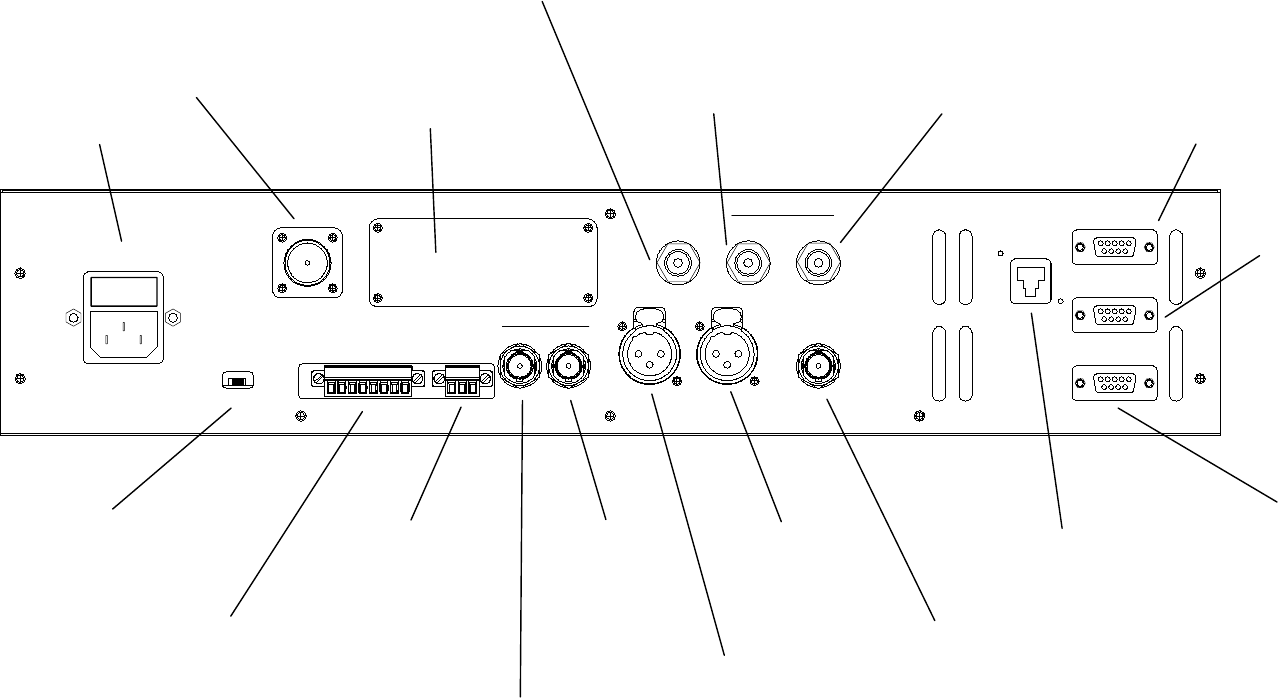
Indoor Unit (IDU) Connections
85 – 265 VAC
2 AMP
ASI
WARNING
48 VDC PRESENT ON
THIS CONNECTOR
70 MHz/
48 VDC/
TM OUT
OFF ON
48 VDC
AUXILIARY
INPUTS
SUMMARY
ALARM
OUT IN
OUT IN
AUDIO2 IN AUDIO1 IN
SDI
IN
W/ AUDIO
VIDEO IN
RS-232 DCE
TELEMETRY
RS-232
CONTROL
RS-232
AUX DATA
10/100
ETHERNET
70 MHz
ODU POWER
DISCONNECTS DC
POWER TO ODU
CONNECTOR
AUDIO2 IN
BALANCED
ANALOG AUDIO
FROM SOURCE
70 MHz OUT
TO SPECTRUM
MONITOR
70 MHz IN
INPUT FROM
EXTERNAL
MODULATOR
AUXILIARY INPUTS
4 AUX CONTROL POINTS
APPLY GROUND HERE TO
CLOSE RELAYS 1-4 ON ODU
AUDIO1 IN
BALANCED
ANALOG AUDIO
FROM SOURCE
VIDEO IN
NTSC
COMPOSITE
VIDEO
SUMMARY ALARM
CONTACT CLOSURE TO
EXTERNAL ALARM
ANNUNCIATOR
COAXIAL CONNECTION
(TRIAX OPTIONAL)
TO TCII-ODU-(X)
OUTDOOR UNIT
70MHZ IF, DC POWER, AND
CONTROL SIGNALS
(TYPE “N”)
ACCESSORY PANEL
FOR EXTERNAL ODU POWER
OPTION OR COMPONENT
VIDEO OPTION
SDI IN
FULL BW SERIAL DIGITAL
VIDEO INPUT WITH
EMBEDDED AUDIO
ASI OUT
MPEG2 COMPRESSED
VIDEO OUT TO ASI
MUX OR MONITOR
ASI IN
FROM EXTERNAL
SD OR HD
ENCODER
RS-232 DCE
DATA SIDE
CHANNEL INPUT
NORMALLY FROM
GPS RECEIVER
RS-232
EXTERNAL
SERIAL
CONTROL
AUX RS-232
OUTPUT FROM MAST
MOUNTED SURE-
SHOT™ POSITION
SENSOR
ETHERNET PORT
RJ-45 FOR EXTERNAL
WEB CONTROL
(SECOND PORT ON
FRONT PANEL)
AC POWER IN
Figure 7 TCII Indoor Unit Rear Panel Connections
18
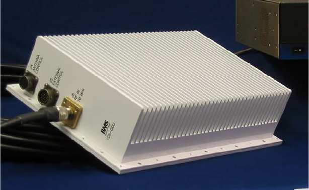
Installing the Outdoor Unit (ODU)
Figure 8 TCII Outdoor Unit
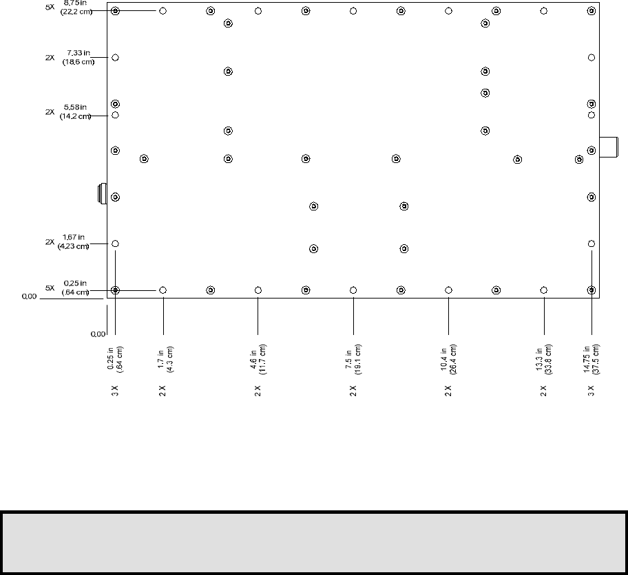
The ODU is designed to be mounted on an antenna mast using a custom mast mount specifically designed for
the mast. See Figure 9 for footprint requirements, hole sizes and hole locations to aid in the design of the
custom antenna mast mount.
This Page Intentionally Left Blank
19
Figure 9 ODU Mounting Footprint
1. Secure the ODU to the custom antenna mast mount with 16-#10 screws (included in installation kit BMS
P/N 7614191020.)
Note:
The Orientation of the ODU is critical to the performance of the TCII system. The ODU must be mounted on
the Antenna mast so that the RF connectors are down. (Figure 10)

20
UP
Figure 10 ODU Mounting Orientation
2. Make the appropriate connections to the ODU.
3. All unused connectors must be capped and sealed to protect the ODU from the weather & elements. See
Table 6.
Table 6 Connector Caps
Connecter Connector Protection Cap BMS P/N
(Use self vulcanizing tape to secure seal.)
J1 – External Data In 210061400
J4 – Antenna Control 210061400
J5 – External Control 210059901
21
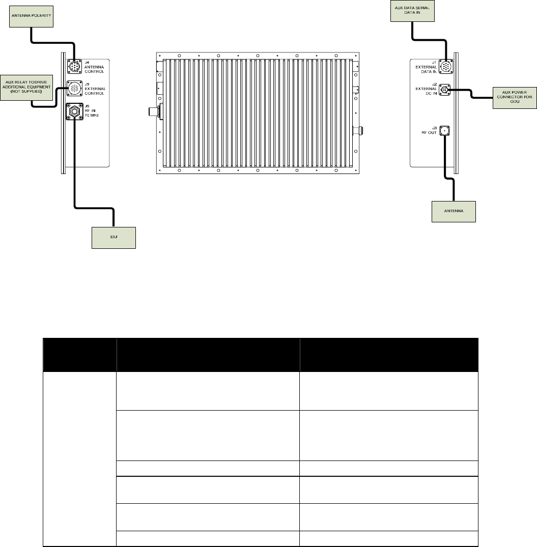
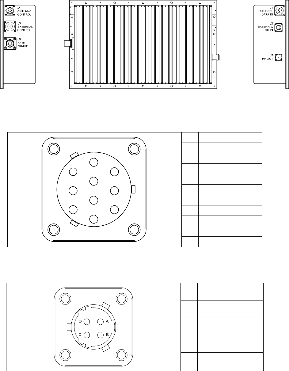
Figure 11 ODU Connections
Table 7 ODU Connections
Component Connection Connecting Component
J1 EXTERNAL DATA IN Factory Service Port Only – This
connector should be capped and sealed
during operation
J2 EXTERNAL DC IN External 24VDC Power Supply – Most
systems will be powered through the
Coax requiring this connector to be
capped and sealed.
J3 RF OUT ANTENNA
J4 ANTENNA CONTROL To Auxiliary Equipment or capped and
sealed if not used.
J5 EXTERNAL CONTROL To Auxiliary Equipment or capped and
sealed if not used.
Outdoor Unit
(ODU)
J6 RF IN 70 MHz IDU
22
OPERATION
NOTE:
Follow all procedures precisely to ensure initialization & operation.
Initialization
1. Power the TCII on by switching the System Power to the ON position. The green indicator light to the
right of the power switch will turn on immediately.
2. The TCII will immediately go into a diagnostics/test mode and will take about 20 seconds to initialize
before the display is activated.
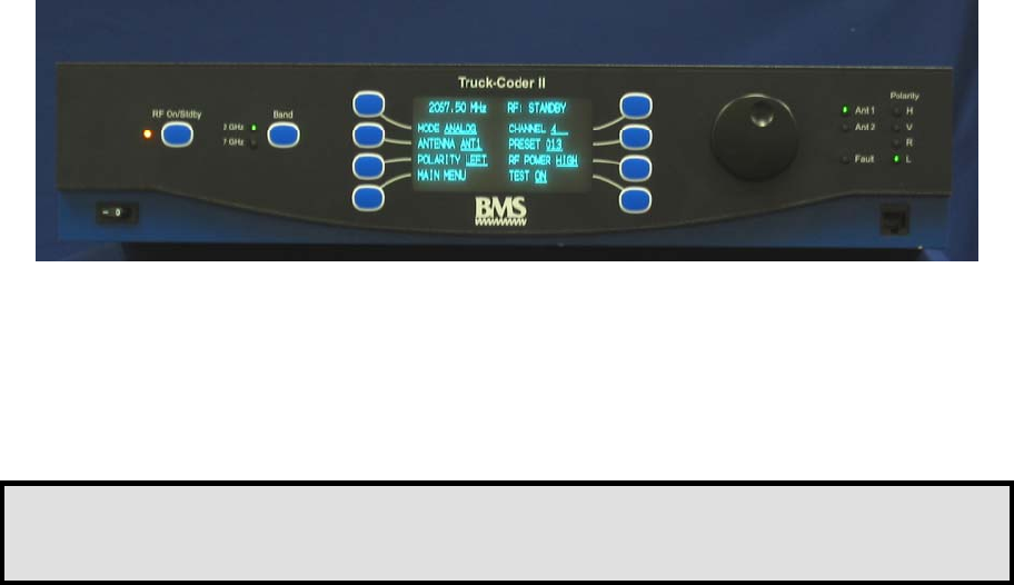
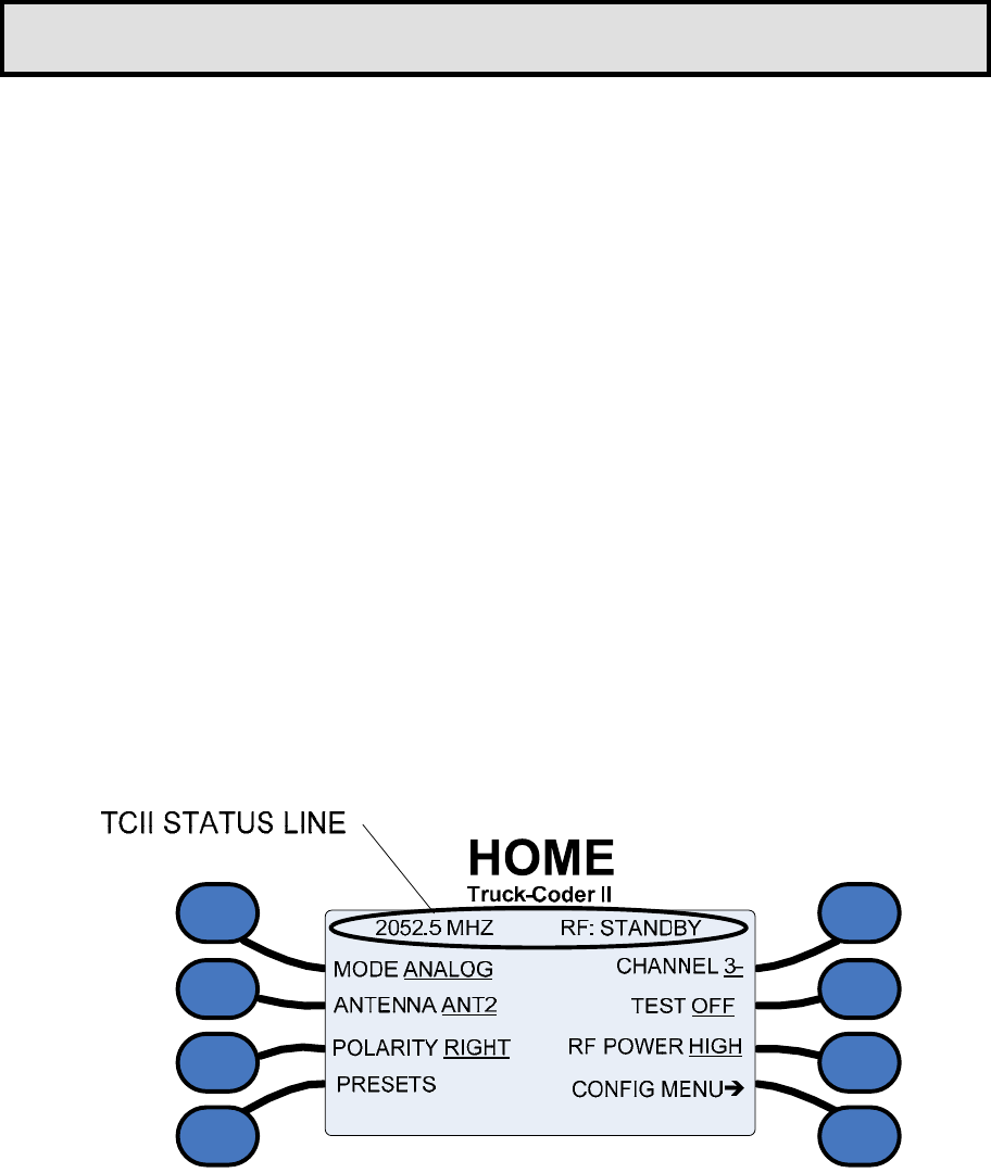
3. Once the internal systems check out, the TCII will display the HOME Screen.
Figure 12 The HOME Menu
This Page Intentionally Left Blank

23
The home menu will display the current transmission frequency and status ( RF: STANDBY or RF: ON) and
various transmission settings.
1. Verify transmission TCII status. The frequency or the Preset Description will appear on the left in the
Status line. The transmission status will appear on the right. The current settings for transmission
MODE, selected ANTENNA, antenna POLARITY , CHANNEL, TEST signal, and RF POWER are
indicated by the underline.
2. If all the settings are correct, begin transmission by pressing the RF On/Standby button on the front
panel. The Status Line will read RF: ON, the LED to the left of the RF On/Standby button will change
from orange to green.
3. To end transmission, switch the transmission mode to standby pressing the RF On/Standby button again.
The Status Line will read RF: STANDBY and the RF Indicator LED will return to orange.
4. The system may now be shut down by switching the System Power switch to the OFF position.
24
25
WARRANTY
BMS warrants that, at time of delivery, the product will be free from defects in materials and workmanship,
provided the equipment or system is installed, operated and maintained in accordance with the Operation and
Maintenance manual or such other BMS documentation as may be applicable. Any such defect reported to
BMS within two years, BMS will take reasonable and prompt action to repair or replace such equipment.
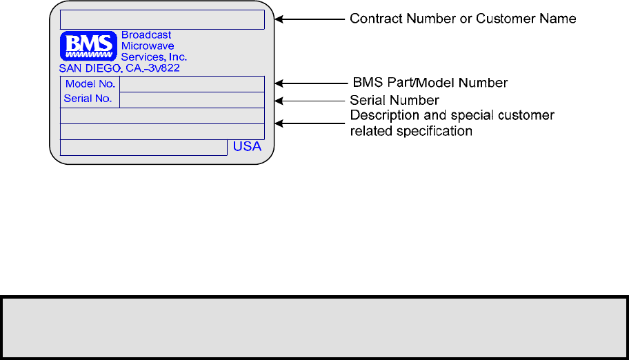
Should any of the components be defective, please contact BMS immediately. Please have the following
information available so we can best serve you.
• Customer Name
• Contract Number
• BMS Model Number
• Serial Number
• Detailed Description of Problem
• Name of Contact Person
• Contact Information such as phone number and/or email address
• Return Information
Much of this information can be found on the product label found on the component.
Figure 13 Product Label
Defective components under BMS warranty will be repaired/replaced at the discretion of BMS. Items no
longer under warranty will require a PO before repairs can proceed.
NOTE:
All goods returned for service require an RMA #. Any goods received without an RMA# may not
be processed in a timely manner. Please contact BMS for an RMA#.
Customer Service Information
Broadcast Microwave Services, Inc.
12367 Crosthwaite Circle
Poway, CA 92064
Tel: +1 (858) 391-3050
Toll free (US): 800-669-9667
Fax: +1 (858) 391-3049
Email:support@bms-inc.com
Web: www.bms-inc.com
26
This Page Intentionally Left Blank

27
TROUBLE SHOOTING
The TCII has certain required parameters. When anomalies happen and the TCII starts to operate outside the
specified parameters, the fault indicator light will be activated and the system status will scroll across the top
of the HOME screen.
Below is a list of faults along with the possible causes and solutions.
Fault Cause Solution
COMMS FAIL IDU not communicating with
ODU.
Check connections. Shut down
then restart the TCII to reset.
DIGITAL COMM FAIL Internal Failure Shut down then restart system to
reset. If fault is still present, then
contact BMS.
FAIL-SAFE MODE The TCII has experienced a failure
that caused the transmission to be
shut down.
Shut down then restart system to
reset. If the TCII is still in FAIL-
SAFE mode, identify the fault and
follow the recommended solution.
IFU PLL UNLOCK Internal Failure Shut down then restart system to
reset. If fault is still present, then
contact BMS.
INPUT RF POWER TOO HIGH RF Power at ODU exceeds limit Check RF Power Out at IDU
INPUT RF POWER TOO LOW RF Power at ODU too low Check RF Power Out at IDU, check
coaxial connections
INPUT RF POWER UNSTABLE Too much power fluctuation Check the coaxial connections
INPUT VOLTAGE TOO HIGH Possible power supply failure Check for 48 V@ IDU out. Contact
BMS
INPUT VOLTAGE TOO LOW Not enough voltage into ODU Check connections, Check cable
impedance/ verify setting in TCII.
Check for 48V out @ IDU.
PA TEMPERATURE GETTING
HIGH
PA Temp between 73º C and 85º C RF Power will automatically go
into LOW power mode. Limit
transmission and/or Wait for
Temperature to fall below 73º C.
PA TEMPERATURE TOO
HIGH
PA Temp has exceeded 85º C Put in STANDBY Mode. Wait for
ODU to cool.
POST/BIST FAIL Internal Failure Shut down then restart system to
reset. If fault is still present, then
contact BMS.
RF OUTPUT POWER TOO
HIGH
Exceeded the RF Power Output
Limit
Contact BMS
RF OUTPUT POWER TOO
LOW
Not enough RF Output Power Check connections
RFU PLL UNLOCK Internal Failure Shut down then restart system to
reset. If fault is still present, then
contact BMS.
THERMAL SETBACK PA Temp above 73º C. RF Power
is automatically reduced
Limit transmission. Wait for PA
Temp to fall below 73º C.
THERMAL SHUTDOWN PA Temp above 85º C. RF
transmission automatically shut
down.
Wait until PA Temp falls below 73º
C for normal transmission.

28
Diagnostics
The Diagnostic Table contains a list of the most common problem symptoms and their solution.
Symptom Possible Cause Solution
Tone at receive site - Video OK Test signal turned on at
transmitter
On HOME Menu, select TEST OFF
No RF at receive site Wrong frequency, polarity
or mode.
Unit is in Standby
Wrong antenna selected or
antenna not directed at
receiver
Verify that settings on HOME menu
match those at receiver.
Place transmitter in transmit by pressing
RF On/Standby button.
Green LED -- Transmit
Amber LED – Standby
Make sure correct antenna is selected
and pointed at receive site.
Receiver shows signal strength,
but no picture or sound
Audio/video connections
Wrong
modulation/encoding
parameters selected
See below
Ensure that Modulation, and MPEG
encoding settings match those of
receiver.
Video is intermittent or poor
quality - transmitter displays
video alarm
Bad connection on video
input.
Check cable and connections,
particularly cable reels and camera
terminations.
Video appears “smeared” or
pixilated, particularly during
movement.
Encoding/decoding errors
or incompatibility
Ensure that MPEG settings match those
of receiver. Video/audio/pcr PIDS
Audio is intermittent Bad connection on audio
input.
Check cable and connections,
particularly cable reels and microphone
terminations.
If you have attempted the solution and the symptoms have not resolved or if you are experiencing a symptom
not listed please contact BMS.
Customer Service Information
Broadcast Microwave Services, Inc.
12367 Crosthwaite Circle
Poway, CA 92064
Tel: +1 (858) 391-3050
Toll free (US): 800-669-9667
Fax: +1 (858) 391-3049
Email:support@bms-inc.com
Web: www.bms-inc.com
29
30
PIN OUTS
IDU
85 – 265 VAC
2 AMP
ASI
WARNING
48 VDC PRESENT ON
THIS CONNECTOR
70 MHz/
48 VDC/
TM OUT
OFF ON
48 VDC
AUXILIARY
INPUTS
SUMMARY
ALARM
OUT IN
OUT IN
AUDIO2 IN AUDIO1 IN
SDI
IN
W/ AUDIO
VIDEO IN
RS-232 DCE
TELEMETRY
RS-232
CONTROL
RS-232
AUX DATA
10/100
ETHERNET
70 MHz
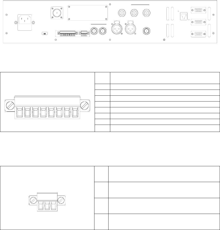
Figure 14 IDU REAR PANEL CONNECTORS
Table 8 AUXILIARY INPUT PINOUTS
PIN Description
1 RELAY 1
2 RELAY 2
3 RELAY 3
4 RELAY 4
5 RETURN 1
6 RETURN 2
7 RETURN 3
AUXILIARY
INPUTS
1 8 RETURN 4
The auxiliary inputs are control inputs that transferred to the ODU output (J5 EXTERNAL CONTROL PIN
OUT) for control of auxiliary equipment.
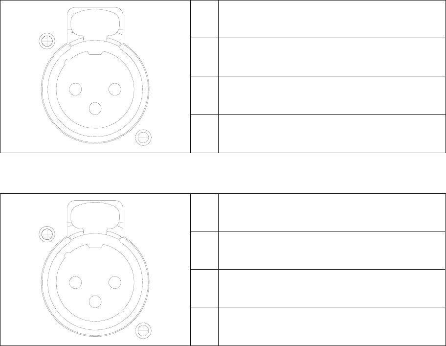
Table 9 SUMMARY ALARM PINOUTS
PIN Description
1
NC
2 COM
1
SUMMARY
ALARM
3 NO
31
Table 10 AUDIO 1 IN PINOUTS
PIN Description
1 GND
2 POS
1
3
2
3 NEG
Table 11 AUDIO 2 IN PINOUTS
PIN Description
1 GND
2 POS
1
3
2
3 NEG
32
ODU
Figure 15 ODU CONNECTORS
Table 12 J1 EXTERNAL DATA IN
PIN Description
A NC
B RESERVED
C GND
D NC
E NC
F NC
G GND
H RESERVED
J RESERVED
A
B
C
D
E
F
G
H
J
K
K RESERVED
Table 13 J2 EXTERNAL DC IN PIN OUTS (Optional)
PIN Description
A + V DC
B +V DC
C Return
D Return
33
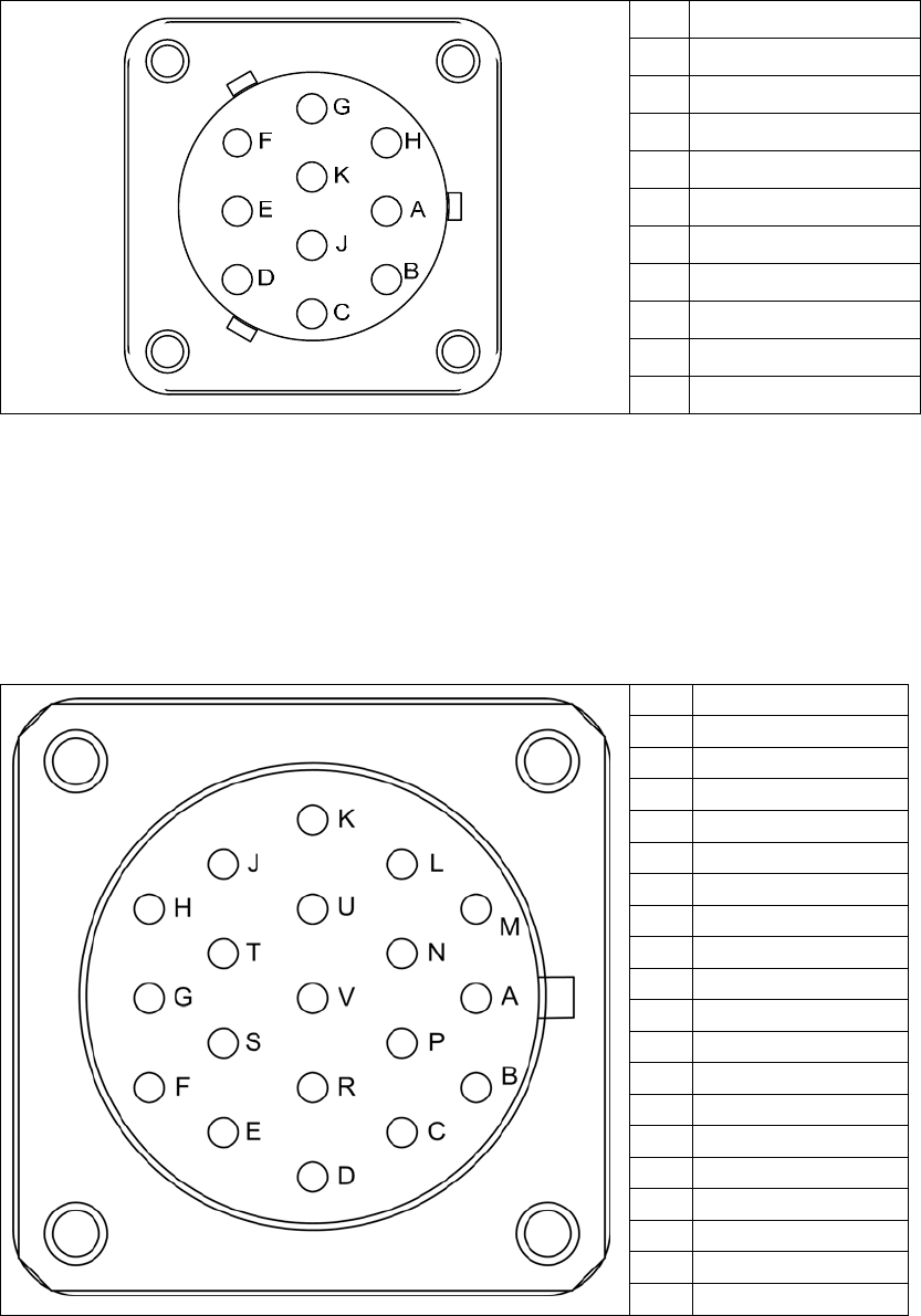
Table 14 J4 ANTENNA CONTROL PIN OUTS
PIN Description
A +24 V
B GROUND
C ANT2
D BAND
E H POLE
F V POLE
G LC POL
H BMS POLE E
J FEED TYPE
K BMS POLE F
Feed Type is configured by the cable connector.
Jumper pins J – A for NSI
Jumper pins J – B for MRC
Table 15 ODU J5 EXTERNAL CONTROL PIN OUT
PIN Description
A Not Used
B AUX 2-NO
C AUX 2 –NC
D Not Used
E AUX 3 – NC
F AUX 3 – NO
G Not Used
H AUX 4 – NO
J AUX 4 – NC
K Not Used
L AUX 1 – NC
M AUX 1 – NO
N AUX 1 – C
P AUX 2 – C
R Not Used
S AUX 3 – C
T AUX 4 – C
U Not Used
V Not Used

34
US Broadcast Frequency Assignments
Old BAS Channel Plan
2 GHz (S) Band
1990-2110 MHz
17 MHz CW
1 1994.75 1999.00 2003.25
2 2012.25 2016.50 2020.75
3 2029.25 2033.50 2037.75
4 2046.25 2050.50 2054.75
5 2063.25 2067.50 2071.75
6 2080.25 2084.50 2088.75
7 2097.25 2101.50 2105.75
New BAS Channel Plan
2 GHz (S) Band
1990-2110 MHz
12 MHz CW
12 MHz CS
A1r 2028.50 2031.50 2034.50
A2r 2040.50 2043.50 2046.50
A3r 2052.50 2055.50 2058.50
A4r 2064.50 2067.50 2070.50
A5r 2076.50 2079.50 2082.50
A6r 2088.50 2091.50 2094.50
A7r 2100.50 2103.50 2106.50
2.5 GHz (S) Band
2450-2500 MHz
17 MHz CW
17 MHz CS
8 2454.25 2458.50 2462.75
9 2471.25 2475.50 2479.75
10 2487.75 2492.00 2496.25
6 GHz (C)
Low Band
6425-6525 MHz
25 MHz CW
25 MHz CS
1 6431.00 6437.50 6444.00
2 6456.00 6462.50 6469.00
3 6481.00 6487.50 6494.00
4 6506.00 6512.50 6519.00
7 GHz (C)
High Band
6875-7125 MHz
25 MHz CW
25 MHz CS
1 6881.00 6887.50 6894.00
2 6906.00 6912.50 6919.00
3 6931.00 6937.50 6944.00
4 6956.00 6962.50 6969.00
5 6981.00 6987.50 6994.00
6 7006.00 7012.50 7019.00
7 7031.00 7037.50 7044.00
8 7056.00 7062.50 7069.00
9 7081.00 7087.50 7094.00
10 7106.00 7112.50 7119.00
13 GHz Band
12700-13250 MHz
25 MHz CW
25 MHz CS
1 12706.25 12712.50 12718.75
2 12731.25 12737.50 12743.75
3 12756.25 12762.50 12768.75
4 12781.25 12787.50 12793.75
5 12806.25 12812.50 12818.75
6 12831.25 12837.50 12843.75
7 12856.25 12862.50 12868.75
8 12881.25 12887.50 12893.75
9 12906.25 12912.50 12918.75
10 12931.25 12937.50 12943.75
11 12956.25 12962.50 12968.75
12 12981.25 12987.50 12993.75
13 13006.25 13012.50 13018.75
14 13031.25 13037.50 13043.75
15 13056.25 13062.50 13068.75
16 13081.25 13087.50 13093.75
17 13106.25 13112.50 13118.75
18 13131.25 13137.50 13143.75
19 13156.25 13162.50 13168.75
20 13181.25 13187.50 13193.75
21 13206.25 13212.50 13218.75
22 13231.25 13237.50 13243.75
35
This Page Intentionally Left Blank

36
Coded Orthogonal Frequency Division Multiplex (COFDM)
Modulation
COFDM is used for microwave applications like wireless cameras and mobile video links because of its
tolerance to multipath transmission errors. In addition COFDM offers more than twice the spectral efficiency
of comparable FM analog microwave transmission.
COFDM does not rely on the vulnerability of a single carrier but spreads the digital information over many
narrow band carriers using Frequency Division Multiplex (FDM). The bandwidth and the data rate on each of
these carriers are reduced and therefore the RF robustness is increased. The carriers are accurately spaced and
orthogonal, which means they can be generated and recovered without carrier specific filtering. Even though
the spectra of adjacent carriers significantly overlap, each carrier can be demodulated without crosstalk from
its neighbors.
The main COFDM parameters are:
• Number Of Sub-Carriers (About 2,000 In Our Case)
• The Symbol
• Individual Sub-Carrier Modulation
• Guard Interval (GI) Duration Between COFDM Symbols
• Data Redundancy Code Rate Used For Error Correction
Symbols
The active symbol is the period that digital information is sampled. The number of bits carried in each
symbol depends on the choice of modulation.
Modulation
Modulation is the process of varying a carrier signal in order to use that signal to convey information.
Quadrature amplitude modulation (QAM) is a modulation scheme which conveys data by changing
(modulating) the amplitude and phase of two carrier waves. BMS uses the forms QPSK, 16QAM, and
64QAM.
QPSK 2 bits/symbol
16 QAM 4 bits/symbol
64 QAM 6 bits/symbol
The higher-order QAM has a higher susceptibly to noise and other corruption. 64QAM will transmit more
bits per symbol but with higher bit error rate. It is a less robust signal, but over an easy transmission path
(studio setting) it probably won’t matter. More difficult transmission paths (mobile or aerial over long ranges
with lots of interference from trees and buildings) will require a more robust signal.
Guard Interval (GI)
The guard interval acts as a buffer to protect the active symbol from echoes. A guard interval is added to the
beginning of each symbol to allow time for echoes to settle before beginning the active symbol period. A
wide range of guard interval options are available from to . This fraction represents the ratio between the
guard interval to the active symbol period.
37
Code Rate
The code rate represents the amount of Forward Error Correction (FEC) used for each active symbol. FEC is
a method of obtaining error control in data transmission. A code rate of ½ means that for two bits of
information received, 1 bit is the real data. The other bit tells how intact the first bit is. A code rate of 7/8
means that out of the 8 bits sent, there are 7 bits of real data and only 1 bit that is to catch any errors in those
7.
Transmission Rates
Finding the best transmission mode to suit a given situation means selecting the best compromise between
modulation, guard interval and code rate. What follows the ETSI EN 300 744 V1.4.1 (2001-01) standards for
the useful bitrate (Mbit/s) for all combinations of guard interval, constellation and code rate for non-
hierarchical systems for 6, 7, and 8 MHz channels respectively

Modulation Code
Rate
Transport Rate (Mb/s) at each
Guard Interval for 6 MHz BW Transport Rate (Mb/s) at each
Guard Interval for 7 MHz BW Transport Rate (Mb/s) at each Guard
Interval for 8 MHz BW
1/4 1/8 1/16 1/32 1/4 1/8 1/16 1/32 1/4 1/8 1/16 1/32
1/2 3,7322 4,147 4,391 4,524 4,354 4,838 5,123 5,278 4,98 5,53 5,85 6,03
2/3 4,976 5,529 5,855 6,032 5,806 6,451 6,830 7,037 6,64 7,37 7,81 8,04
3/4 5,599 6,221 6,587 6,786 6,532 7,257 7,684 7,917 7,46 8,29 8,78 9,05
5/6 6,221 6,912 7,318 7,540 7,257 8,064 8,538 8,797 8,29 9,22 9,76 10,05
QPSK
7/8 6,532 7,257 7,684 7,917 7,620 8,467 8,965 9,237 8,71 9,68 10,25 10,56
1/2 7,465 8,294 8,782 9,048 8,709 9,676 10,246 10,556 9,95 11,06 11,71 12,06
2/3 9,953 11,059 11,709 12,064 11,612 12,902 13,661 14,075 13,27 14,75 15,61 16,09
3/4 11,197 12,441 13,173 13,572 13,063 14,515 15,369 15,834 14,93 16,59 17,56 18,10
5/6 12,441 13,824 14,637 15,080 14,515 16,127 17,076 17,594 16,59 18,43 19,52 20,11
16QAM
7/8 13,063 14,515 15,369 15,834 15,240 16,934 17,930 18,473 17,42 19,35 20,49 21,11
1/2 11,197 12,441 13,173 13,572 13,063 14,515 15,369 15,834 14,93 16,59 17,56 18,10
2/3 14,929 16,588 17,564 18,096 17,418 19,353 20,491 21,112 19,91 22,12 23,42 24,13
3/4 16,796 18,662 19,760 20,358 19,595 21,772 23,053 23,751 22,39 24,88 26,35 27,14
5/6 18,662 20,735 21,955 22,620 21,772 24,191 25,614 26,390 24,88 27,65 29,27 30,16
64QAM
7/8 19,595 21,772 23,053 23,751 22,861 25,401 26,895 27,710 26,13 29,03 30,74 31,67
2 Figures in italics are approximate values.
This Page Intentionally Left Blank
Glossary
Analog
Transmission
Frequency Modulated (FM) method of sending information with
radio waves. An older, dependable method of transmission.
(See Digital Transmission)
Antenna Actuator The mechanism which deploys or retracts the antenna radio
operation or for landing and take-off.
ASI: Asynchronous
Serial Interface.
Transmission standard used to connect video delivery
equipment within a cable, satellite or terrestrial plant.
BNC Connector The Bayonet Neill-Concelman connector is a type of RF
connector used for terminating coaxial cable. (See TNC
connector)
COFDM: Coded
Orthogonal
Frequency Division
Multiplex
A digital modulation method that divides a single digital signal
across multiple (1000+) signal carriers simultaneously. BMS
Coder II family products use COFDM digital modulation.
Composite Video The format of an analog television (picture only) signal before
it is combined with a sound signal and modulated onto an RF
carrier.
dB: Decibel A unit for expressing the ratio of two amounts of electric or
acoustic signal power equal to 10 times the common logarithm
of this ratio.
dBm A unit for expressing the power ratio in decibel (dB) of the
measured power referenced to one milliwatt (mW).
Digital
Transmission
Digitally Modulated (COFDM and others) method of sending
information with radio waves. Newer more reliable method of
transmission. (See Analog Transmission)
Directional Antenna The final transmit element of a microwave system that
radiates the signal one direction, in a directed or focused
narrow beam. This requires aiming of the antenna toward the
receive site.
DTV: Digital
Television
Digital Television uses digital modulation and compression to
broadcast video, audio and data signals.
DVB-T:
Digital Video
Broadcasting-
Terrestrial
An international digital television (DTV) standard that defines
digital COFDM modulation using MPEG2 compression.
GPS: Global
Positioning System
A navigational system using satellite signals to fix the location
of a receiver on or above the earth surface.
MPEG-2 A compression standard for digital video and audio data.
Multipath The radio wave propagation phenomenon that results in the
transmitted signals. reaching the receiving antenna by two or
more paths. This condition is not desirable and usually results
in signal fading and interference.
MUX
Multiplex
The combining of multiple signals into a single transmission.
Omni-Directional
Antenna
The final transmit element of the microwave system that
radiates the signal approximately equally throughout a 360
degree circle. Does not require aiming of the antenna.
PAL phase-
alternating line
A color encoding used in broadcast television systems in large
parts of the world.
PAT
Program
Association Table
Indicates which PID the PMT is to be found
PID Packet Identifier
PMT-PID
Program Map Table
Yields information about the Program, Video PID, Audio PID,
and PCR PID. The PMT-PID default is 200 for BMS systems.
PCR-PID
Program Clock
Reference
A time stamp indicating the system time clock value when the
stamped packet leaves the encoder buffer and enters the
decoder buffer used to Synchronize the receiver System Time
Clock (STC) with the transmitter STC. Default is 101 for BMS
systems.
RF: Radio
Frequency
That portion of the Electromagnetic Spectrum that is used for
radio and television transmission.
SDI: Serial Digital
Interface
A digitized video format used for broadcast grade video.
Stand-by The condition of an RF system where all but the transmit
circuits are energized. In this status the system may be
switched into transmit mode instantaneously. (See Transmit)
TNC Connector Threaded version of the BNC connector (See BNC connector)
Transmit The condition of an RF system where it is sending out signal.
(See Stand-by)
YUV The YUV model defines a color space in terms of one
luminance and two chrominance components. YUV is used in
the PAL system of television broadcasting, which is the
standard in much of the world.