Brooks Automation HF5 Inductive Tag Reader User Manual RS232 A5 E 1 4 HF SECS1
Brooks Automation (Germany) GmbH RFID Division Inductive Tag Reader RS232 A5 E 1 4 HF SECS1
UserManual.wiki
>
Brooks Automation
>
HF5 User Manual
Users Manual
Navigation menu
Upload a User Manual
Namespaces
Wiki Guide
HTML
PDF
Info
Views
User Manual
Discussion / Help
Navigation
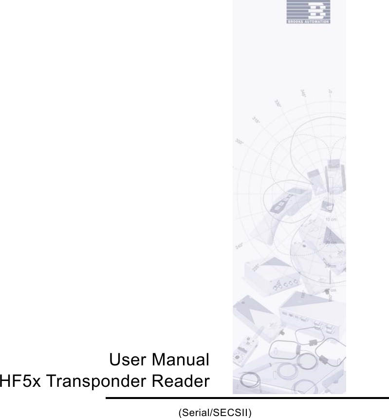

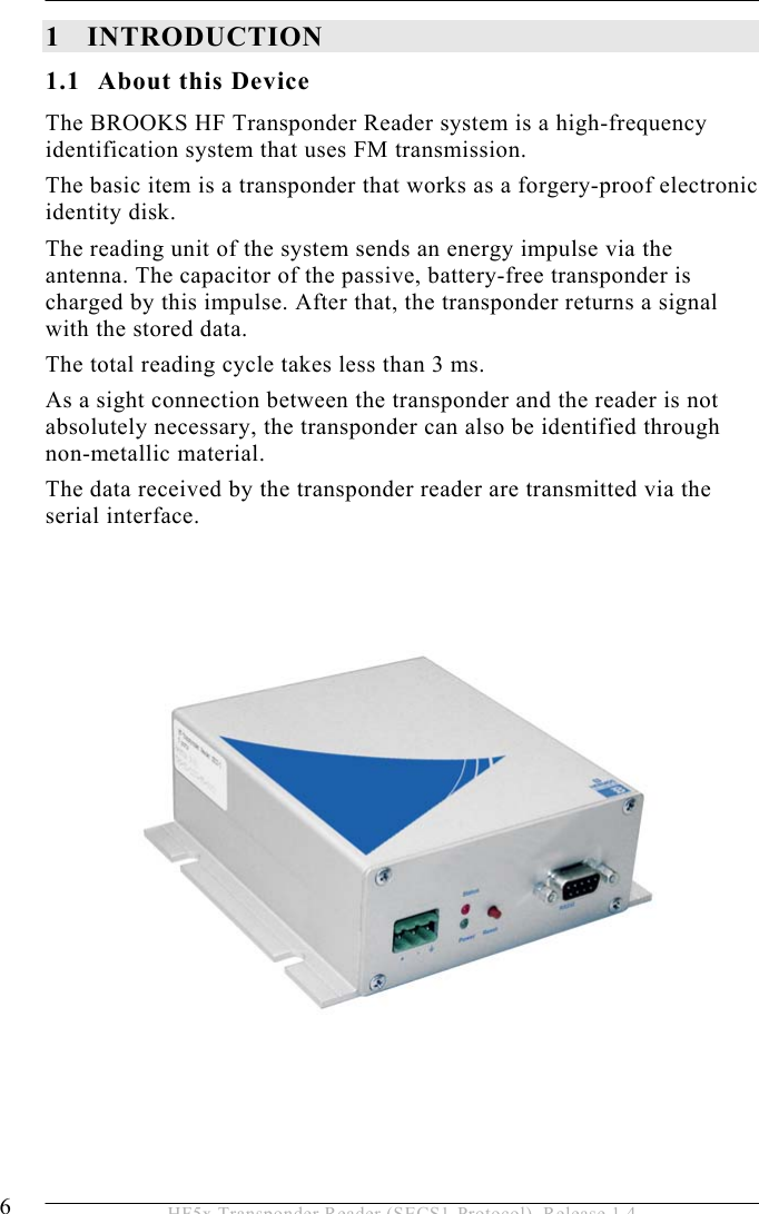

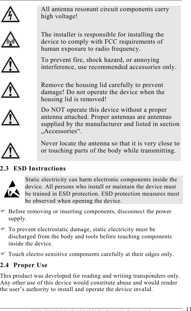


![5 OPERATION 36 HF5x Transponder Reader (SECS1-Protocol), Release 1.4 A list is an ordered set of elements, where an element can be either an item or a list. The list header has the same form as an item header with format type 0. However, the length byte refers to the number of elements in the list rather than to the number of bytes. 5.4.2 Data Items The formats represent arrays of types: <type>[number of elements] where <type> is one of the following: Oct-Code Hex-Code Format Meaning Example 00 01 List List element with the number of the “Length” data elements <L2> <A “Hello”> <B 0x00> 11 25 Boolean 1 – Byte Boolean false = 00 ; true != 00 <Boolean1 0x00> 10 21 Binary Byte sequence of the length “Length” <B1 0x01> 20 41 ASCII Printable ASCII signs <A “Hello”> 31 65 I1 1 - Byte signed Integer <I1 123> 32 69 I2 2 - Byte signed Integer <I2 –12345> 34 71 I4 4 - Byte signed Integer <I4 2147483647> 30 61 I8 8 - Byte signed Integer <I8 931372980293834> 51 A5 U1 1 - Byte unsigned Integer <U1 0> 52 A9 U2 2 - Byte unsigned Integer <U2 #empty> 54 B1 U4 4 - Byte unsigned Integer <U4 429489725> 50 A1 U8 8 - Byte unsigned Integer <U8 763468676756767> 40 91 F8 8 - Byte floating point <F8 1.223 e204> 44 81 F4 4 - Byte floating point <F4 -1.23 >](https://usermanual.wiki/Brooks-Automation/HF5/User-Guide-635221-Page-36.png)
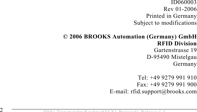
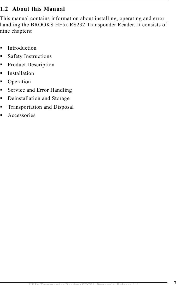
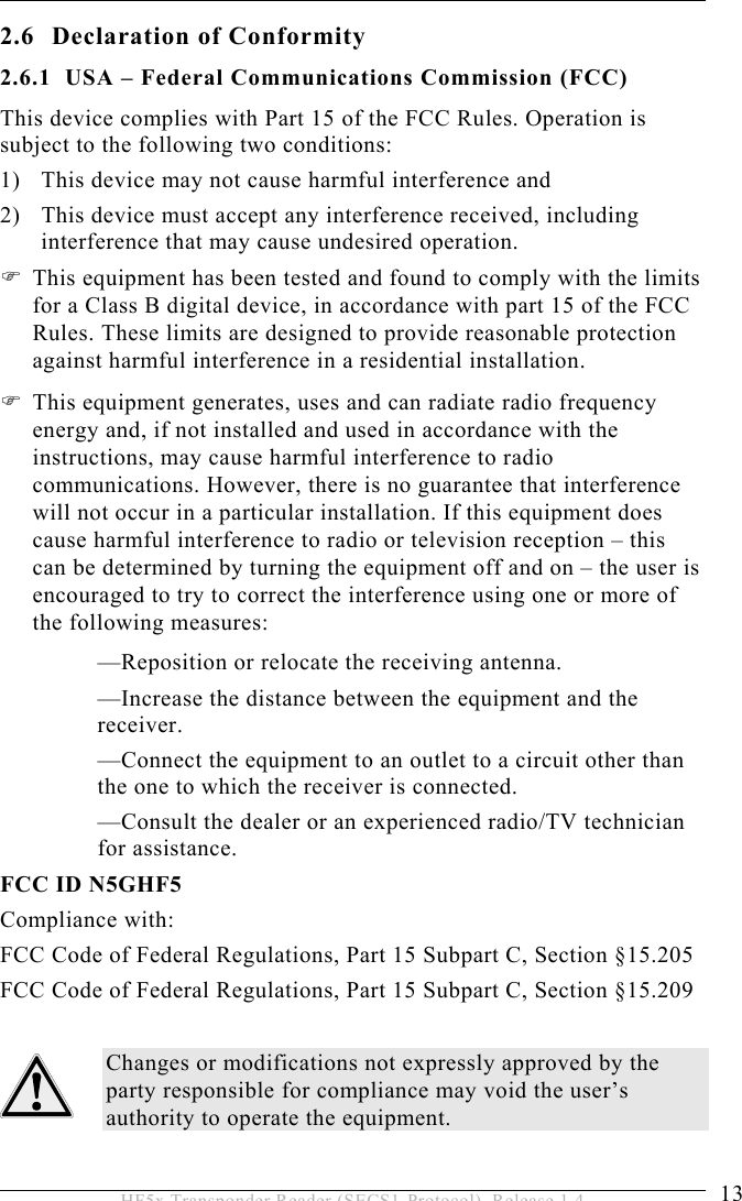
![OPERATION 5 39 HF5x Transponder Reader (SECS1-Protocol), Release 1.4 Data Item Dictionary This section defines the data items used in the standard SECS-2 messages described in the section “Message Details”. Syntax: Name: A unique name for this data item. This name is used in the message definitions. Format: The permitted item format code which can be used for this standard data item. Item format codes are shown in hex and octal, as described in section data items (page 36). The notification “3()” indicates any of the signed integer formats (30, 31, 32, 34). Description: A description of the data item, with the meanings of specific values. Where used: The standard messages in which the data item appears. ALARM STATUS Format: A[1] Description: The value of the alarm status refers to the last reading process. If a read or write error occurs, the alarm status is set. A successful read or write resets the alarm status. When leaving maintenance mode, the alarm status is also deleted. 0 … No alarm 1 … Alarm Where used: STATUS](https://usermanual.wiki/Brooks-Automation/HF5/User-Guide-635221-Page-39.png)
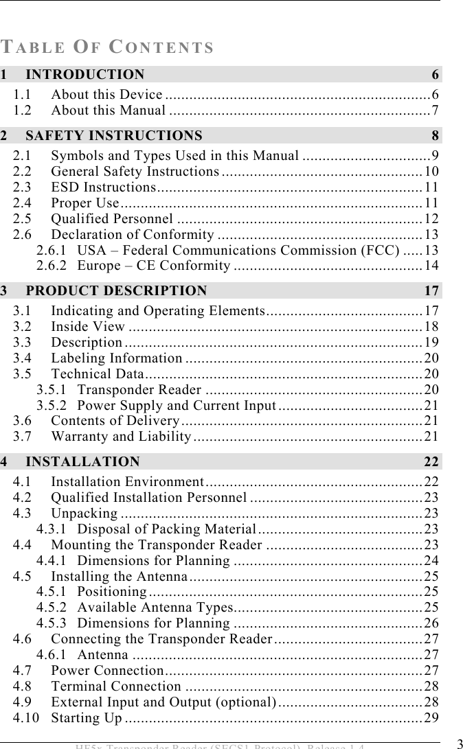
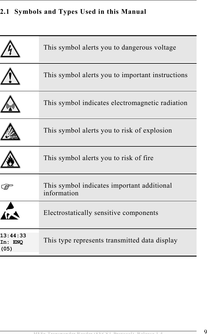
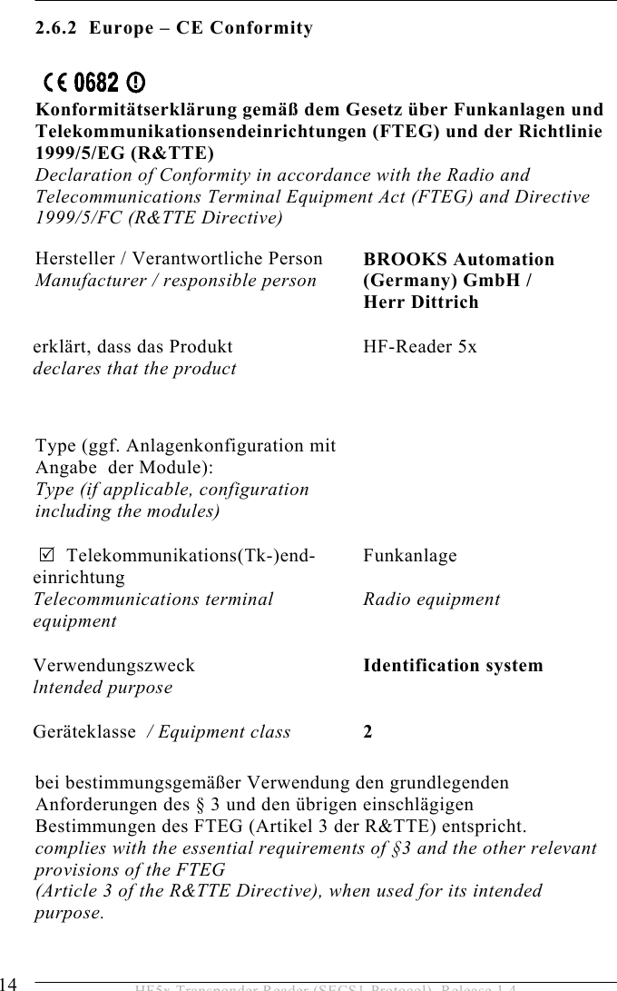
![5 OPERATION 40 HF5x Transponder Reader (SECS1-Protocol), Release 1.4 ATTRID Format: A[max25] Description: Identifier for an attribute for a specific type of object. CIDRW Attribute Definitions: “Configuration”… Number of heads “AlarmStatus” Current CIDRW sub state of ALARM STATUS “OperationalStatus” Current CIDRW sub state of OPERATIONAL “SoftwareRevisionLevel” Revision (version) of software - 8 byte maximum “CarrierIDOffset” Offset of CID in CID field (MID area) “CarrierIDLength” Length of CID in CID field (MID area) “S1Status” Status of external I/O 01 (read only) “S2Status” Status of external I/O 02 (read only) “S3Status” Status of external I/O 03 (read only) “S4Status” Status of external I/O 04 (read only) “S5Status” Status of external I/O 05 (read only) “ECID_00” parameter 0 – Gateway ID “ECID_01” parameter 1 – Baudrate “ECID_02” parameter 2 – Inter-Character-Timeout T1 “ECID_03” parameter 3 – Block-Protocol-Timeout T2 “ECID_04” parameter 4 – Reply-Timeout T3 “ECID_05” parameter 5 – Inter-Block-Timeout T4 “ECID_06” parameter 6 – Retry-Limit RTY “ECID_07” parameter 7 – TARGETID high Byte “ECID_08” parameter 8 – TARGETID low Byte “ECID_09” parameter 9 – Heartbeat time “ECID_11” parameter 11 – Reader ID “ECID_20” parameter 20 – sensor activity “ECID_21” parameter 21 – sensor 1 delay](https://usermanual.wiki/Brooks-Automation/HF5/User-Guide-635221-Page-40.png)
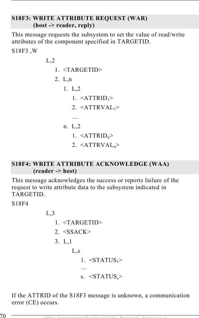
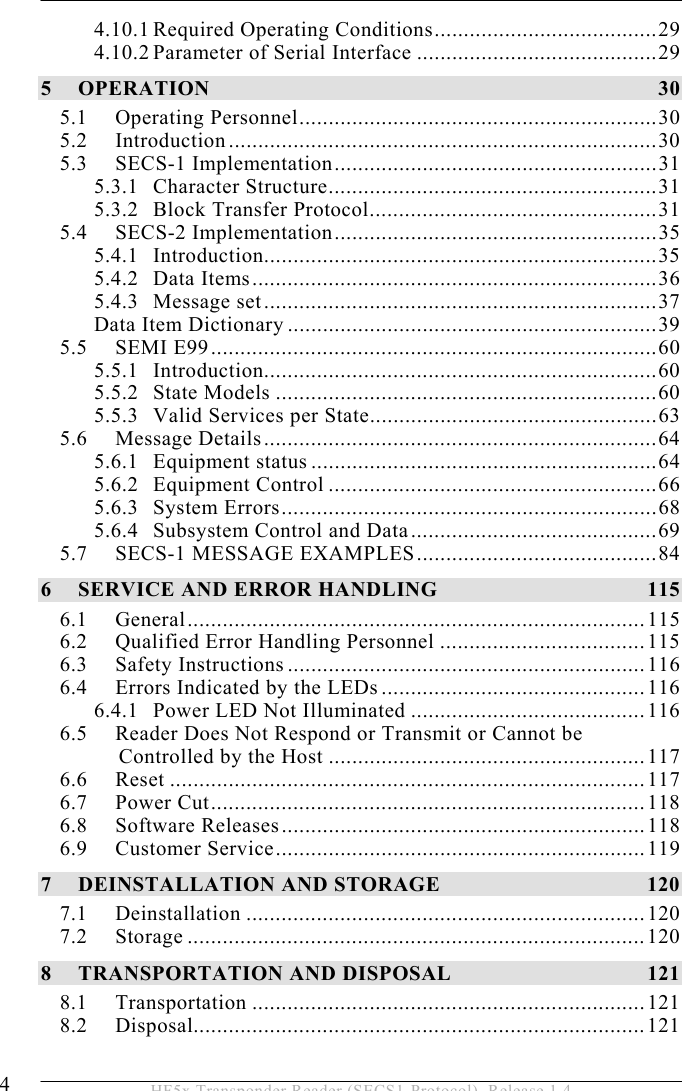
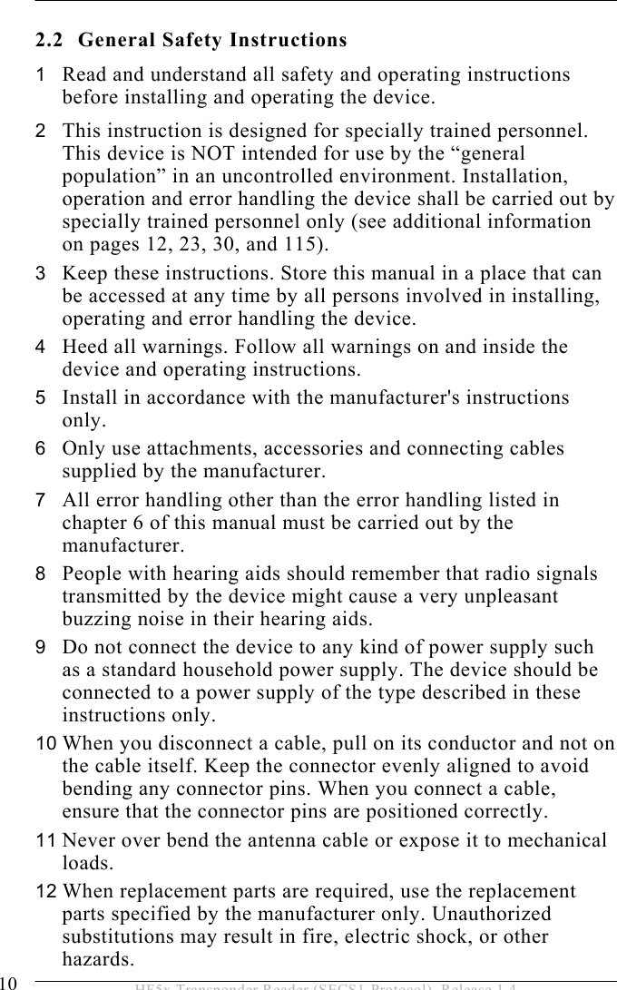
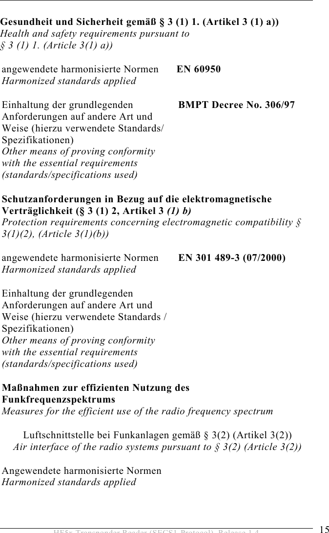
![5 OPERATION 42 HF5x Transponder Reader (SECS1-Protocol), Release 1.4 ATTRVAL Format: A[max4] Description: Value of the specified attribute. CIDRW Attribute Definitions: “Configuration” Number of heads “05” “AlarmStatus” Current CIDRW sub state of ALARM STATUS “0” … NO “1” … ALARMS “OperationalStatus” Current CIDRW sub state of OPERATIONAL “IDLE” … reader in IDLE mode “BUSY” … reader is busy “MANT” … maintenance mode “SoftwareRevisionLevel” Revision (version) of Software – 8 byte maximum “S1Status” – “S5Status” “ON” – Sensor is occupied “OFF” – Sensor is unoccupied ECID_00 to ECID_45 see data item ECV parameter 0 to parameter 45 Head Attribute Definitions: “HeadStatus” The current state “IDLE” … reader in IDLE mode “BUSY” … reader is busy “NOOP”… not operating “HeadID” Head number 01-05 (2 digits) “01” … Antenna 1 … “05” … Antenna 5 Where used: S18F2, S18F3](https://usermanual.wiki/Brooks-Automation/HF5/User-Guide-635221-Page-42.png)
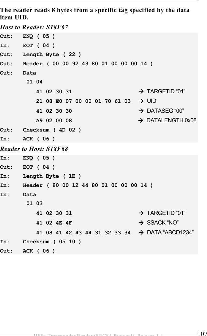
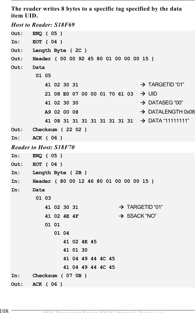
![OPERATION 5 43 HF5x Transponder Reader (SECS1-Protocol), Release 1.4 CPVAL Format: A[max2] Description: State request value “OP” … operating state “MT” … maintenance state Where used: S18F13 DATA Format: A Description: A vector or string of unformatted data. It depends on the size of the MID area. Where used: S18F6, S18F7, S18F68, S18F69 DATALENGTH Format: U2 Description: Total bytes to be sent. The DATALENGTH corresponds to the quantity of bytes that should be read or written. Where used: S18F5, S18F7, S18F67, S18F69 DATASEG Format:A[2] Description: Used to identify the data requested. The DATASEG corresponds to the page number (PAGEID) of the ISO 15693 transponder. “00”: First page of any type of transponder or first page of the DATA area. Where used: S18F5, S18F7, S18F67, S18F69](https://usermanual.wiki/Brooks-Automation/HF5/User-Guide-635221-Page-43.png)
![5 OPERATION 44 HF5x Transponder Reader (SECS1-Protocol), Release 1.4 EAC Format: B[1] Acknowledge code for new reader constant 0 … Parameter was set successfully 1 … Parameter could not be set Where used: S2F16 ECID Format: U1 Parameter number of reader (see data item ECV) Where used: S2F13, S2F15 ECV Format: U1 Reader parameter definition. The values are displayed as decimal values! Where used: S2F14, S2F15 Parameters: Parameter 0: Gateway ID The gateway ID is a part of the device ID. The BROOKS reader works simultaneously as a gateway and a reader (CIDRW with integrated head). It is the “lower message ID” in the message header. 00 .. 255 Default: Last two characters of hex serial number The default gateway ID corresponds to Parameter 8. (Lowbyte TargetID). In special cases the gateway ID is set to a customized value.](https://usermanual.wiki/Brooks-Automation/HF5/User-Guide-635221-Page-44.png)
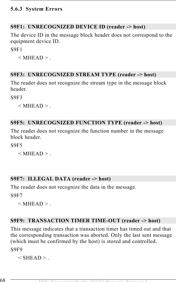
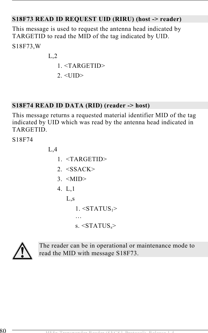
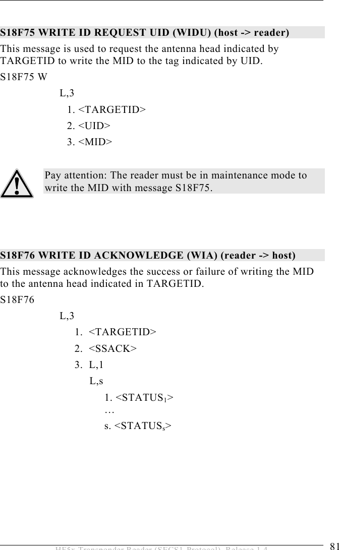
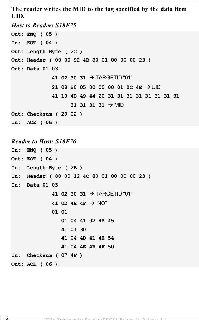
![5 OPERATION 54 HF5x Transponder Reader (SECS1-Protocol), Release 1.4 MDLN Format: A[6] Equipment model number. Where used: S1F2 MHEAD Format: B[10] SECS message block header associated with message block in error. Where used: S9F1, S9F3, S9F5, S9F7 MID Format: A Description: Material ID Depending on the type of transponder, it is possible to modify the length of the MID. MID length can be set from “0” (no MID) to “10” (MID occupies the first 10 pages (writeable)) See parameter 37. Where used: S18F10, S18F11, S18F74, S18F75 OFLACK Format: B[1] Acknowledge code for OFF-LINE request. 0 … OFF-LINE acknowledge (reader is offline) Where used: S1F16](https://usermanual.wiki/Brooks-Automation/HF5/User-Guide-635221-Page-54.png)
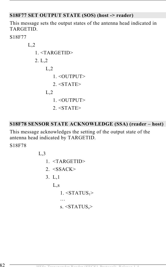
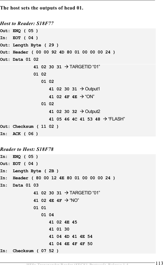
![OPERATION 5 55 HF5x Transponder Reader (SECS1-Protocol), Release 1.4 ONLACK Format: B[1] Acknowledge code for ON-LINE request. 0 … ON-LINE accepted (reader is online) Where used: S1F18 OUTPUT Format: A[2] Number of the output of the antenna head indicated by TARGETID. “01” … Output 1 “02” … Output 2 Where used: S18F77 PM Information Format: A[2] Description: Preventive maintenance information “NE” … Normal execution “MR” … Maintenance required Where used: STATUS RAC Format: B[1] Reset acknowledge code. 0 … Reset to be done 1 … Reset could not be done Where used: S2F20](https://usermanual.wiki/Brooks-Automation/HF5/User-Guide-635221-Page-55.png)
![5 OPERATION 56 HF5x Transponder Reader (SECS1-Protocol), Release 1.4 RIC Format: B[1] Reset code. 1 … Power up reset 2 … Software reset Where used: S2F19 SHEAD Format: B[10] Stored SECS message block header. Only the last message is stored, which must still be confirmed by the host! Where used: S9F9 SOFTREV Format: A[max 6] Software revision code. Where used: S1F2 SSACK Format: A[2] Description: Result information on the status of the request concerning the service request. “NO” … Normal operation Indicates the success of the requested action “EE” … Execute error Cannot read tag data . Cannot read ID sequence. But equipment is normal.](https://usermanual.wiki/Brooks-Automation/HF5/User-Guide-635221-Page-56.png)
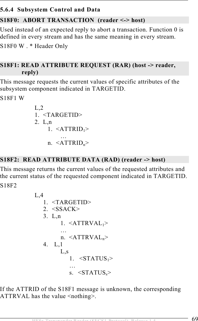
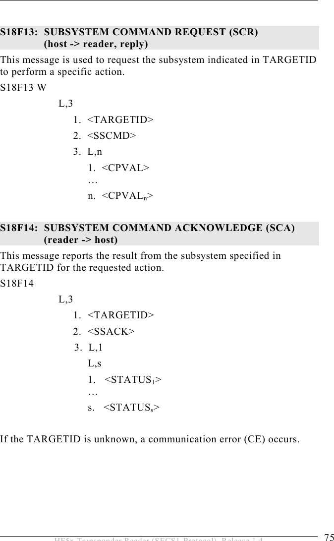
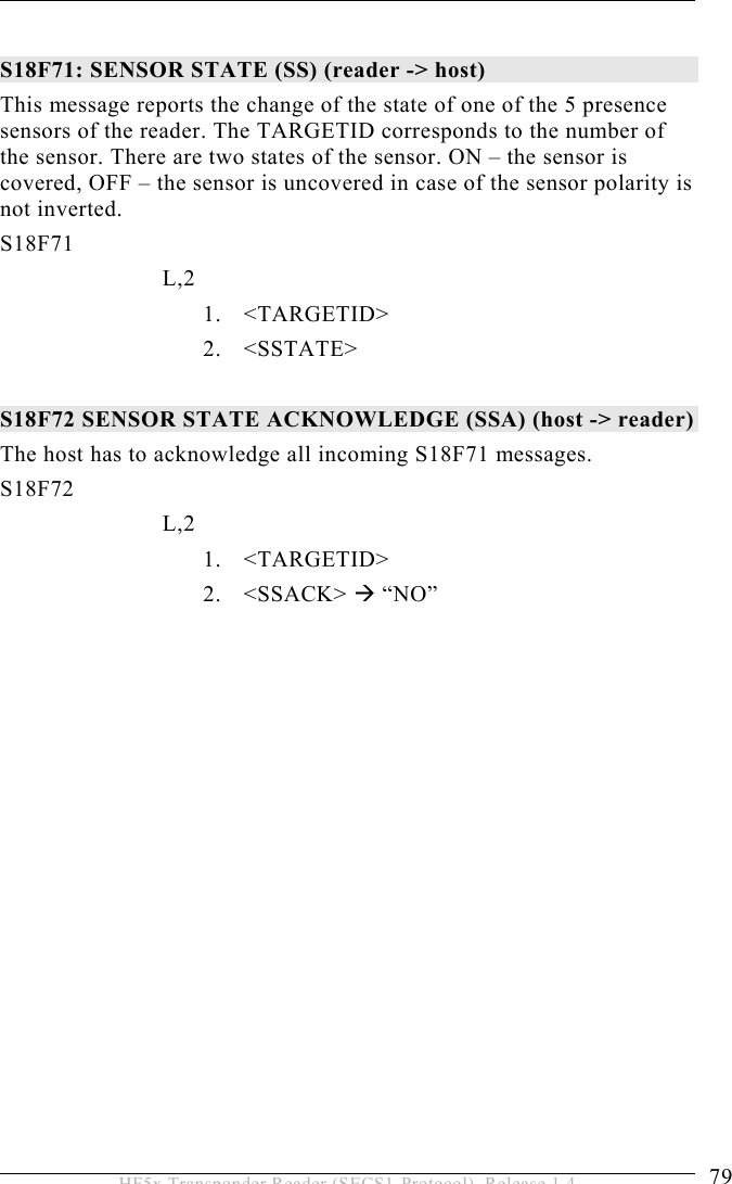
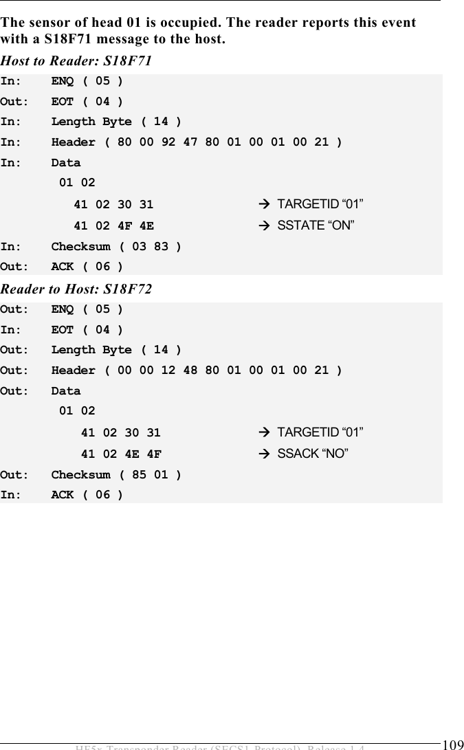
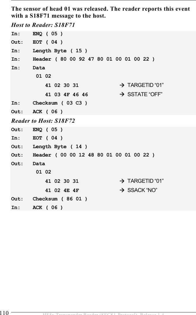
![OPERATION 5 57 HF5x Transponder Reader (SECS1-Protocol), Release 1.4 “CE” … Communication error Syntax error of message or message format or value. “HE” … Hardware error ID reader/writer head fault, ID reader/writer head is powered off. “TE” … Tag error Where used: S18F2, S18F4, S18F6, S18F8, S18F10, S18F12, S18F14, S18F66, S18F68, S18F70, S18F72, S18F74, S18F76, S18F78, S18F80 SSCMD Format: A[max18] Description: Indicates an action to be performed by the subsystem. Used to differentiate between the different subsystem commands indicated. “ChangeState” … Change state “GetStatus” … Get state “PerformDiagnostics” … Perform diagnostics “Reset” … Reset CIDRW Where used: S18F13 SSTATE Format: A[max 3] Description: Provides status information of the external I/O of a specific head. “ON” - Sensor is occupied “OFF” - Sensor is unoccupied Where used: S18F71](https://usermanual.wiki/Brooks-Automation/HF5/User-Guide-635221-Page-57.png)
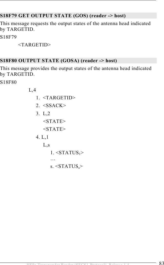
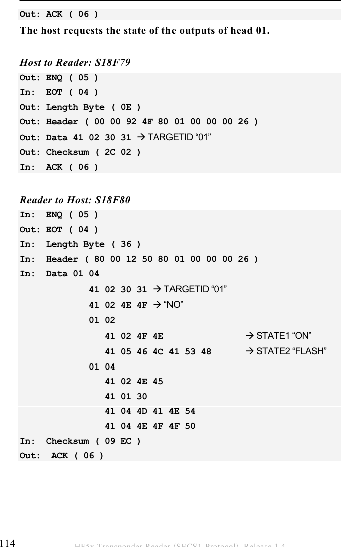
![5 OPERATION 58 HF5x Transponder Reader (SECS1-Protocol), Release 1.4 STATE Format: A[max 5] Description: State of the external outputs of a specific head. “ON” … Output is ON “OFF” … Output is OFF “FLASH” … Output is flashing “KEEP” … Output remains current state Where used: S18F77 STATUS Format: A[2] Description: Provides status information of a subsystem component. Consists of PM Information and the current values of the CIDRW attributes AlarmStatus, OperationalStatus, and HeadStatus. List of a Status L,4 <PMInformation> <AlarmStatus> <OperationalStatus> <HeadStatus> For data items OperationalStatus and HeadStatus see data item ATTRVAL. Where used: S18F2, S18F4, S18F8, S18F10, S18F12, S18F14, S18F70, S18F74, S18F76, S18F78, S18F80](https://usermanual.wiki/Brooks-Automation/HF5/User-Guide-635221-Page-58.png)
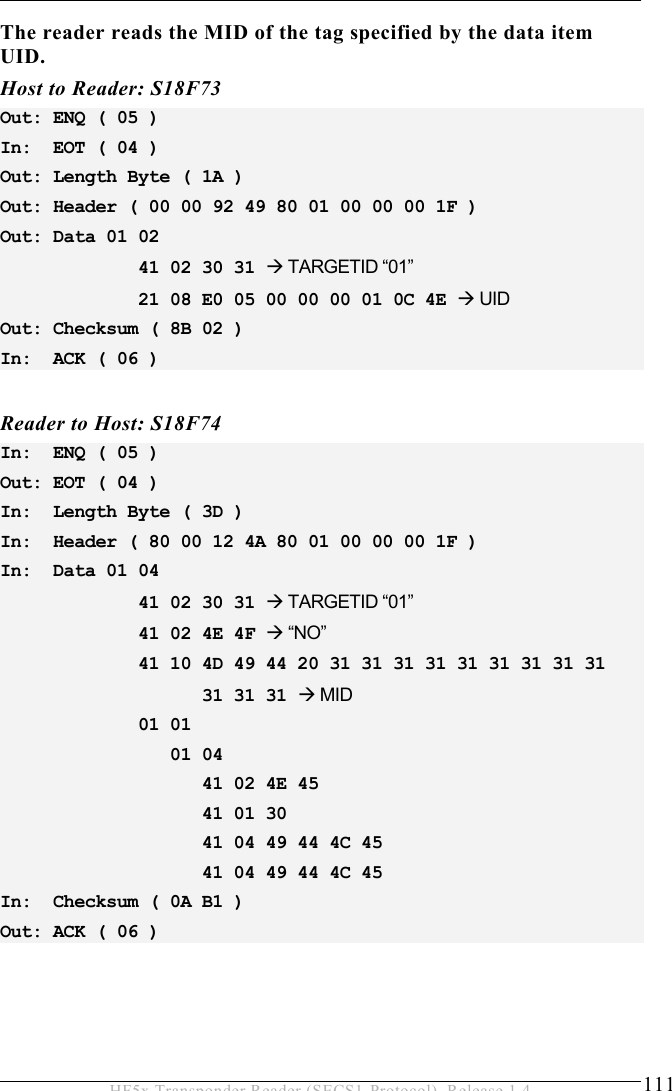
![OPERATION 5 59 HF5x Transponder Reader (SECS1-Protocol), Release 1.4 TARGETID Format: A[max10] Description: Identifies where a request for action or data is to be applied. The TARGETID corresponds to the last four characters of the serial number on a label on top of the reader. The reader uses the 2 digit HeadID as TARGETID to address the right antenna connector. See also reader parameter definitions (data item ECV) parameter 7 and 8. Example : “F5-xxxx-TS” (xxxx … dependent on the individual reader) The 4 ASCII character TARGETID xxxx is set by delivery (is used as serial number). The predefined TARGETID is fixed and cannot be changed. The 2 ASCII character HeadID corresponds to the antenna connectors 01 - 05. Where used: all stream 18 messages UID Format: B[8] Description: Unified identifier of the tag. Where used: S18F66, S18F67, S18F69, S18F73, S18F75](https://usermanual.wiki/Brooks-Automation/HF5/User-Guide-635221-Page-59.png)
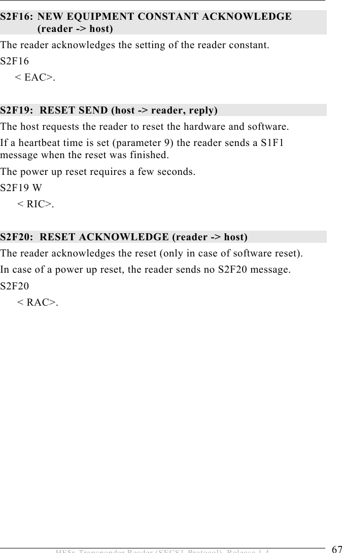
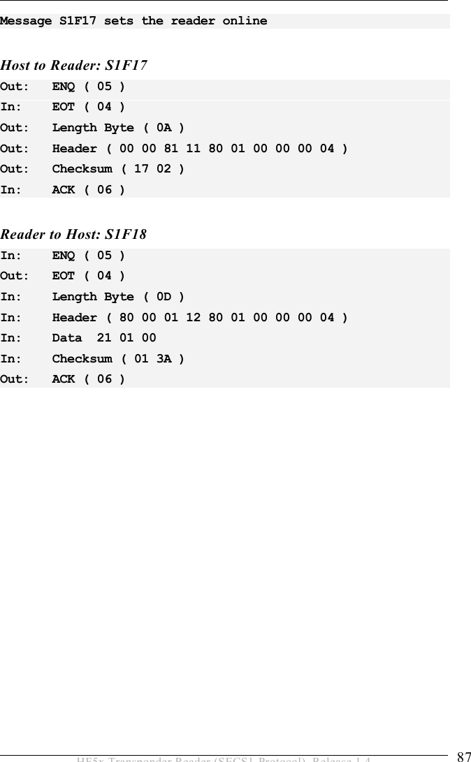
![5 OPERATION 64 HF5x Transponder Reader (SECS1-Protocol), Release 1.4 5.6 Message Details 5.6.1 Equipment status S1F0: ABORT TRANSACTION (reader <-> host) Used instead of an expected reply to abort a transaction. Function 0 is defined in every stream and has the same meaning in every stream. S1F0 W . * Header Only S1F1: ARE YOU THERE REQUEST (reader <-> host, reply) Establishes if the gateway or host is online. S1F1 W . * Header Only S1F2: ON-LINE DATA (host -> reader) The host signifies that it is online. S1F2 <L[2] <MDLN > <SOFTREV > >. S1F2: ON-LINE (reader -> host) The reader signifies that it is online. S1F2 <L[2] <MDLN > <SOFTREV > >.](https://usermanual.wiki/Brooks-Automation/HF5/User-Guide-635221-Page-64.png)
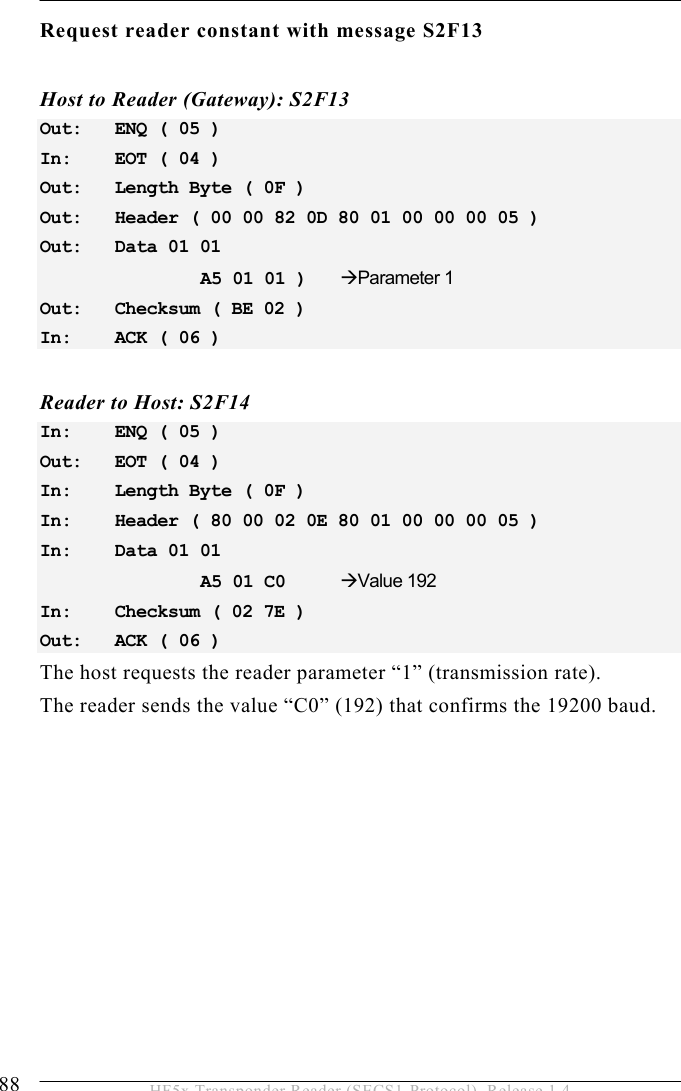
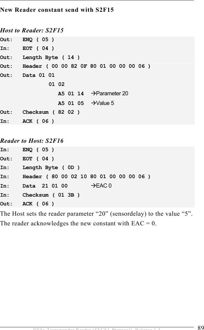
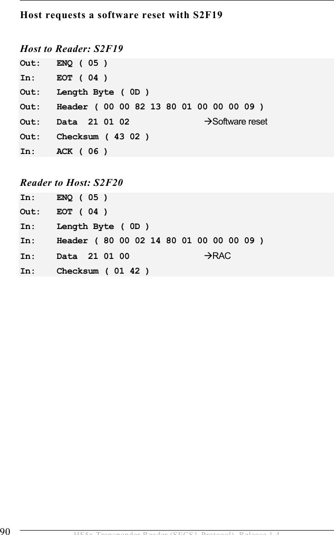
![5 OPERATION 66 HF5x Transponder Reader (SECS1-Protocol), Release 1.4 5.6.2 Equipment Control S2F0: ABORT TRANSACTION (reader <-> host) Used instead of an expected reply to abort a transaction. Function 0 is defined in every stream and has the same meaning in every stream. S2F0 W . * Header Only S2F13: EQUIPMENT CONSTANT REQUEST (host-> reader, reply) The host requests one constant from the reader. S2F13 W <L[1] <ECID> >. S2F14: EQUIPMENT CONSTANT DATA (reader -> host) The reader sends the requested constant to the host. S2F14 <L[1] <ECV> >. S2F15: NEW EQUIPMENT CONSTANT SEND (host-> reader, reply) The host changes one reader constant. S2F15 W <L[1] <L[2] <ECID> <ECV> > >.](https://usermanual.wiki/Brooks-Automation/HF5/User-Guide-635221-Page-66.png)