Brooks Automation LF60 Inductive Reader User Manual LF60 Gen2 S1 A5 E 0 2
Brooks Automation (Germany) GmbH RFID Division Inductive Reader LF60 Gen2 S1 A5 E 0 2
UserManual.wiki
>
Brooks Automation
>
LF60 User Manual
User Manual
Navigation menu
Upload a User Manual
Namespaces
Wiki Guide
HTML
PDF
Info
Views
User Manual
Discussion / Help
Navigation

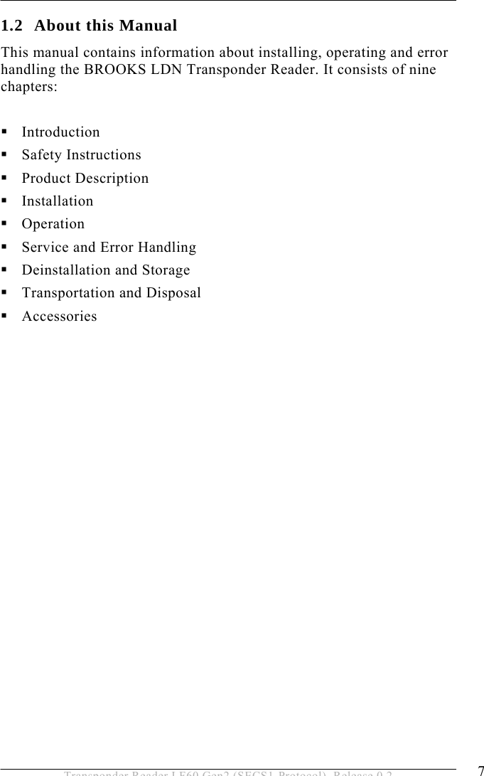
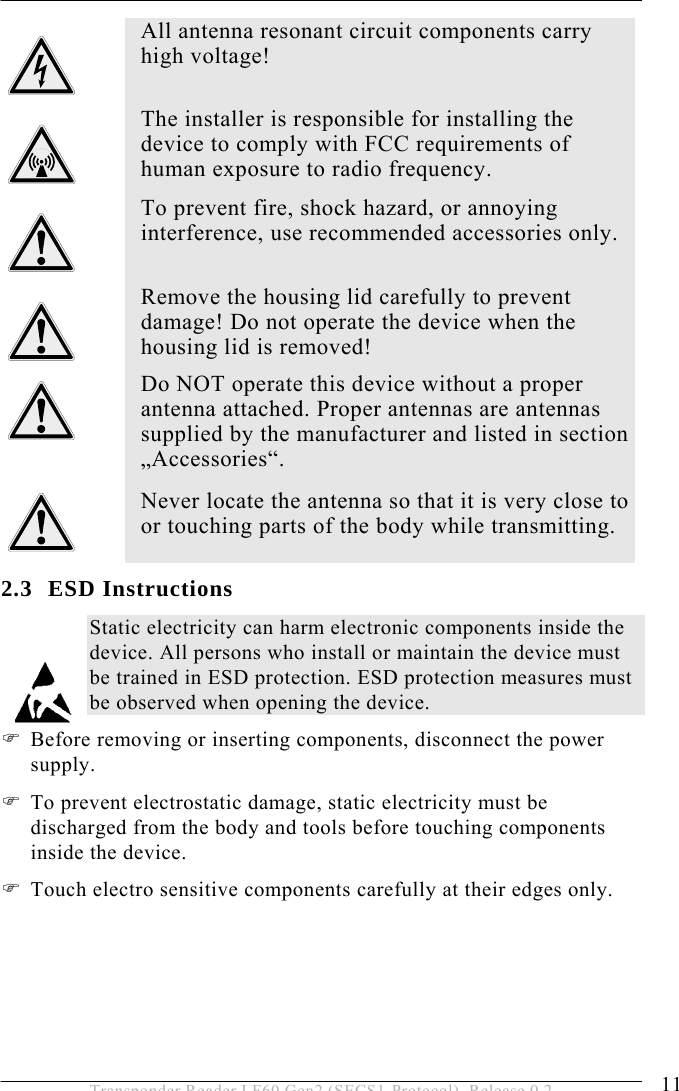


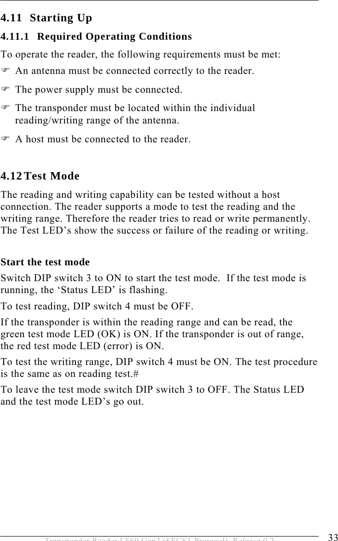
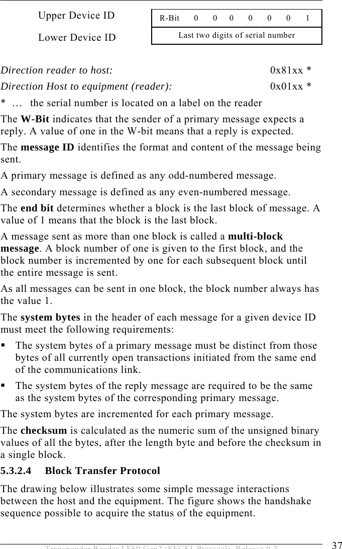
![5 OPERATION 40 Transponder Reader LF60 Gen2 (SECS1-Protocol), Release 0.2 A list is an ordered set of elements, where an element can be either an item or a list. The list header has the same form as an item header with format type 0. However, the length byte refers to the number of elements in the list rather than to the number of bytes. 5.4.2 Data Items The formats represent arrays of types: <type>[number of elements] where <type> is one of the following: Oct-Code Hex-Code Format Meaning Example 00 01 List List element with the number of the “Length” data elements <L2> <A “Hello”> <B 0x00> 11 25 Boolean 1 – Byte Boolean false = 00 ; true != 00 <Boolean 0x00> 10 21 Binary Byte sequence of the length “Length” <B1 0x01> 20 41 ASCII Printable ASCII signs <A “Hello”> 31 65 I1 1 - Byte signed Integer <I1 123> 32 69 I2 2 - Byte signed Integer <I2 –12345> 34 71 I4 4 - Byte signed Integer <I4 2147483647> 30 61 I8 8 - Byte signed Integer <I8 931372980293834> 51 A5 U1 1 - Byte unsigned Integer <U1 0> 52 A9 U2 2 - Byte unsigned Integer <U2 #empty> 54 B1 U4 4 - Byte unsigned Integer <U4 429489725> 50 A1 U8 8 - Byte unsigned Integer <U8 763468676756767> 40 91 F8 8 - Byte floating point <F8 1.223 e204> 44 81 F4 4 - Byte floating point <F4 -1.23 >](https://usermanual.wiki/Brooks-Automation/LF60/User-Guide-948419-Page-40.png)
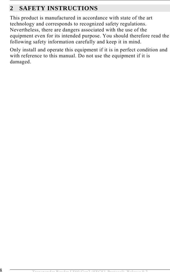
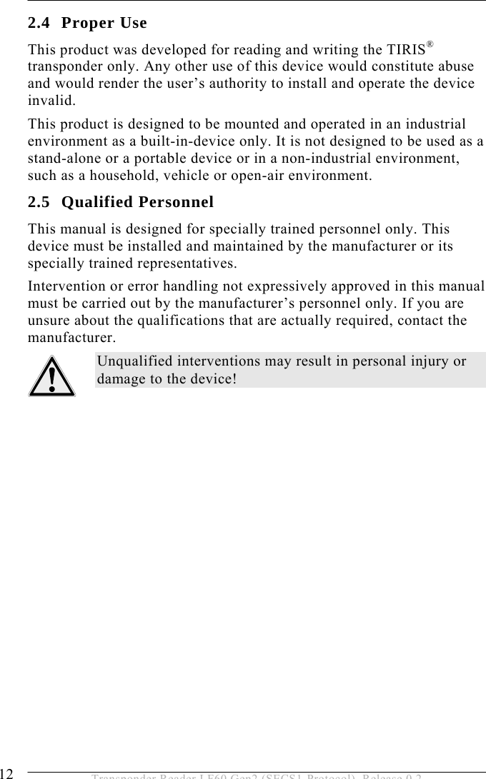
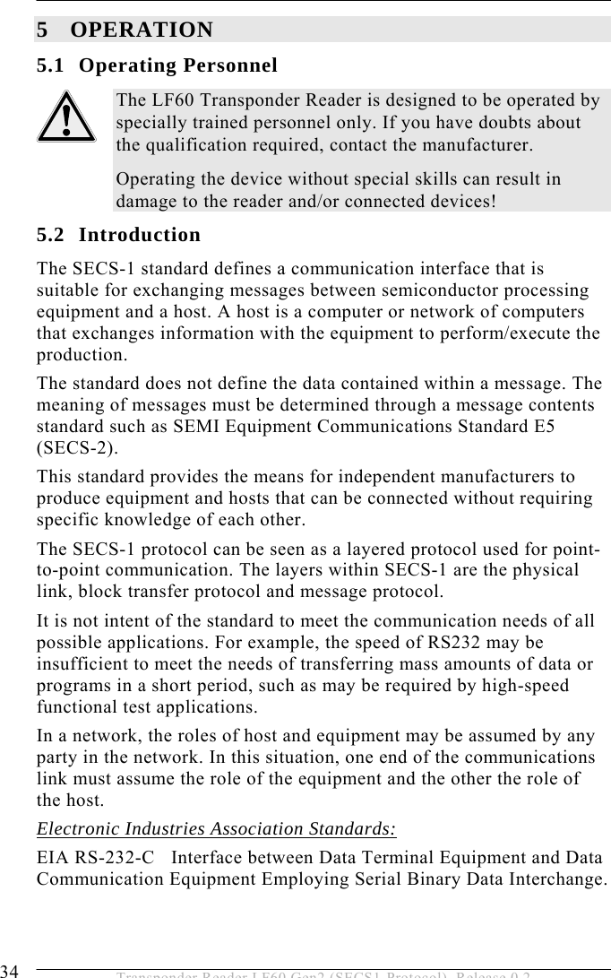
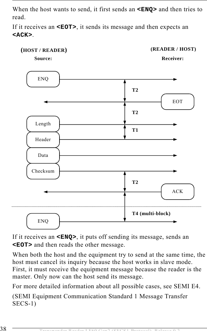
![OPERATION 5 43 Transponder Reader LF60 Gen2 (SECS1-Protocol), Release 0.2 5.4.4 Data Item Dictionary This section defines the data items used in the standard SECS-2 messages described in the section “Message Details”. Syntax: Name: A unique name for this data item. This name is used in the message definitions. Format: The permitted item format code which can be used for this standard data item. Item format codes are shown in hex and octal, as described in section data items (page 40). The notification “3()” indicates any of the signed integer formats (30, 31, 32, 34). Description: A description of the data item, with the meanings of specific values. Where used: The standard messages in which the data item appears. ACKC3 Format: B[1] Acknowledge Code 0 : Sensor 0 was the initiator >0 : Error, not accepted Where used: S3F6, S3F8 ACKC5 Format: B[1] Acknowledge Code 0 : No error >0 : Error, not accepted Where used: S5F2](https://usermanual.wiki/Brooks-Automation/LF60/User-Guide-948419-Page-43.png)
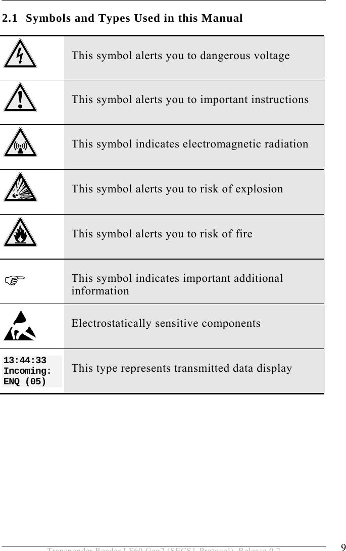
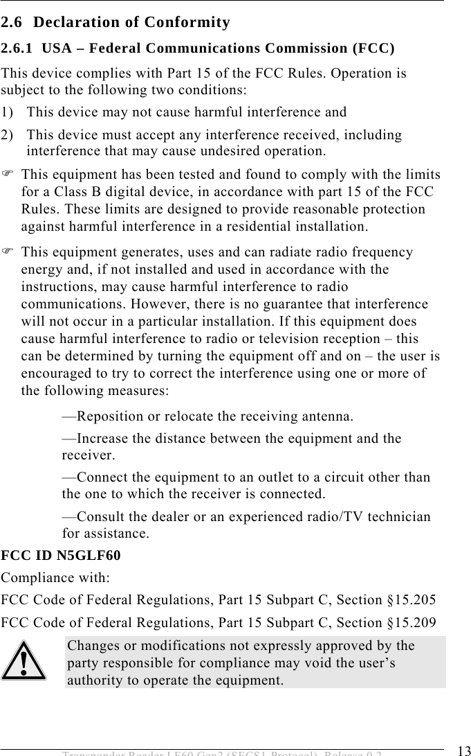
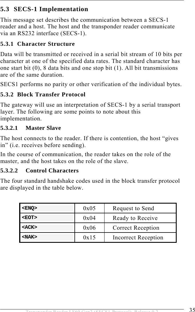
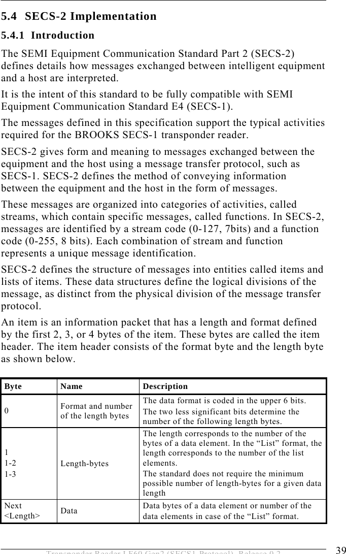
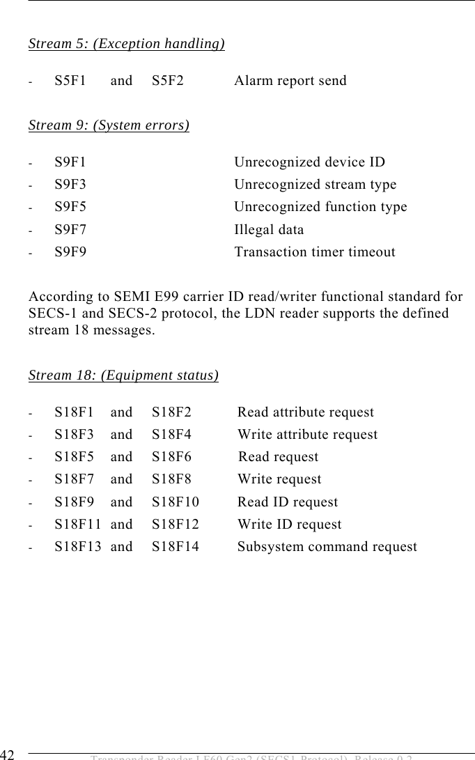
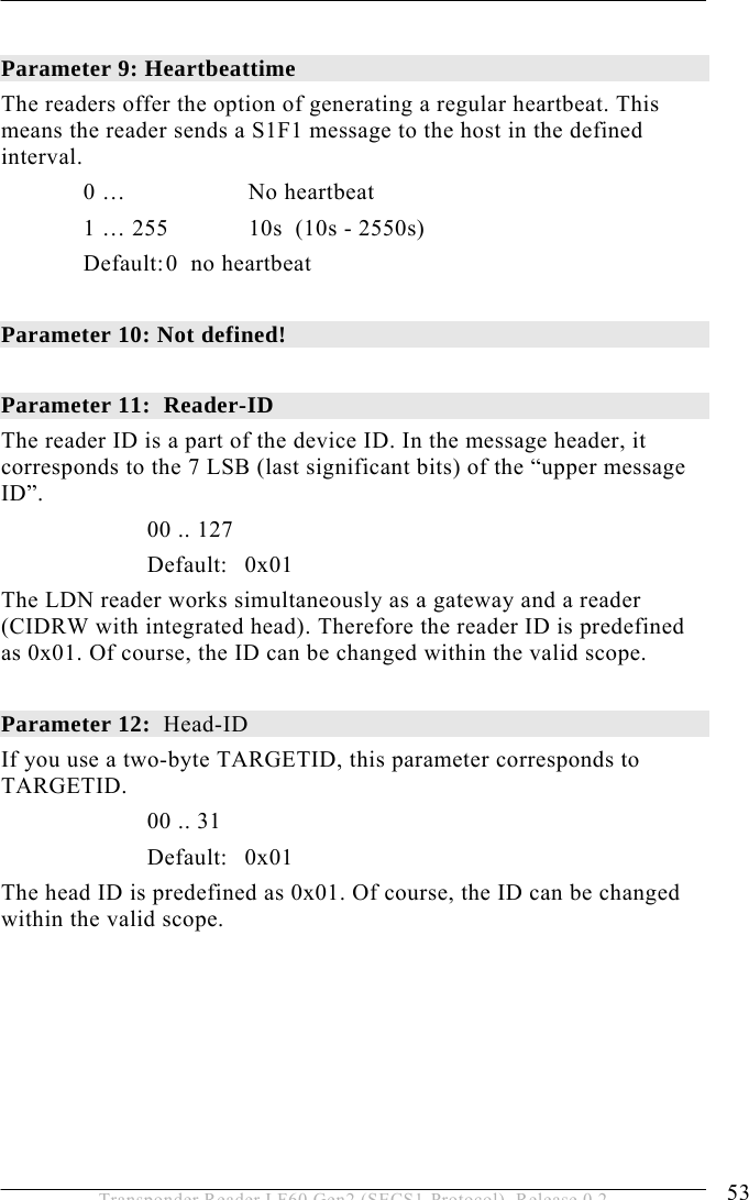
![5 OPERATION 44 Transponder Reader LF60 Gen2 (SECS1-Protocol), Release 0.2 ALARM STATUS Format: A[1] The value of the alarm status refers to the last reading process. If a read or write error occurs, the alarm status is set. A successful read or write resets the alarm status. When leaving maintenance mode, the alarm status is also deleted. 0 : No alarm 1 : Alarm Where used: S18F13 ALCD Format: B[1] Alarm code byte Only the occurrence of a failure is reported. Failures will not be reset on principle. Bit 8 = 1: Alarm is set Where used: S5F1 ALID Format: B[1] Alarm Identifier 0: No error 1: Auto read failed, the reader is engaged 2: External read failed, the reader is engaged 3: External write failed, the reader is engaged 4: No tag could be recognized when the sensor was covered or carrier had been removed prematurely (sensor uncovered!) 5: Invalid command or parameter detected 6: Unknown error 7: Reserved 8: Parity- or checksum error detected 9: Unexpected confirmation was sent](https://usermanual.wiki/Brooks-Automation/LF60/User-Guide-948419-Page-44.png)
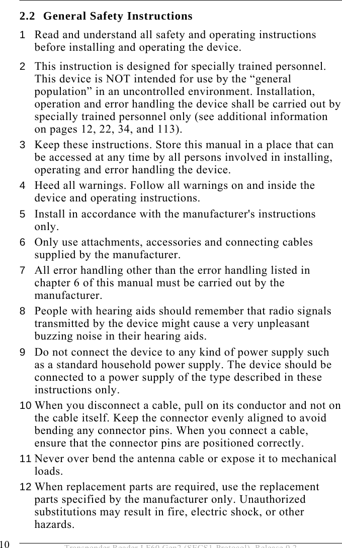
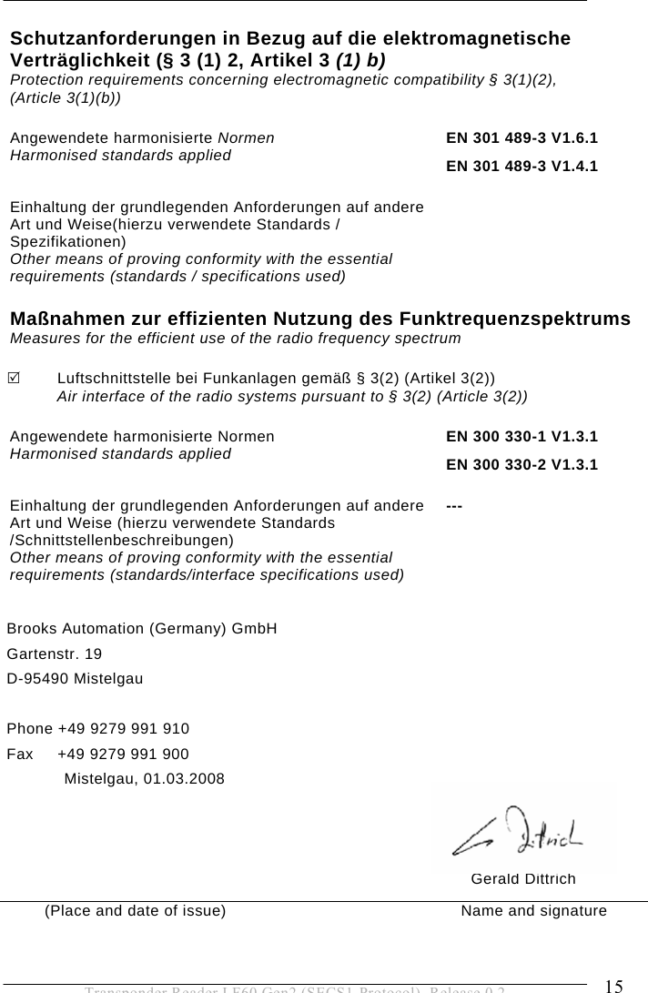
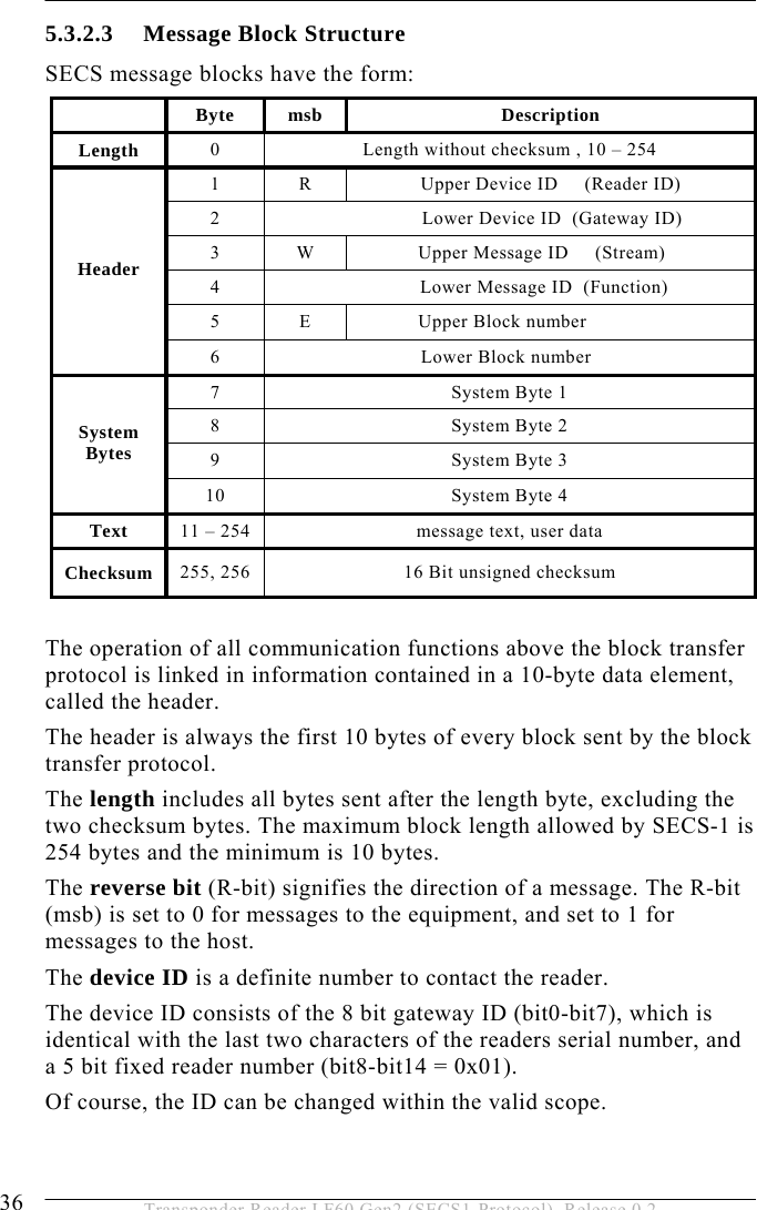
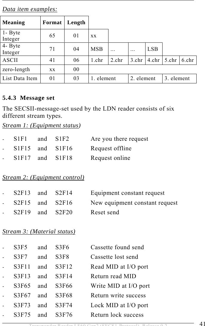
![OPERATION 5 45 Transponder Reader LF60 Gen2 (SECS1-Protocol), Release 0.2 10: Locked page could not be written 11: Reserved 12: Incorrect type of transponder 13: External read or write failed because the sensor is not covered 14: Reserved 15: Reserved 16: Reserved Where used: S5F1 ALTX Format: A[max40] Alarm Text The length of the alarm text is 0 to 40 signs. According to the reader version, state information about the sensor or sensors is also transmitted during a reader failure message. The information should be interpreted as follows: ALTX[0] Initiator of a failure message “0”: Sensor 0 “1”: Sensor 1 (not available) “F”: Cannot be assigned ALTX[1] State of sensor 0 “0”: Sensor not occupied “1”: Sensor is occupied “E”: Sensor state is not available “F”: Sensor not defined ALTX[2] State of sensor 1 “0”: Sensor not occupied “1”: Sensor is occupied “E”: Sensor state is not available “F”: Sensor not defined](https://usermanual.wiki/Brooks-Automation/LF60/User-Guide-948419-Page-45.png)
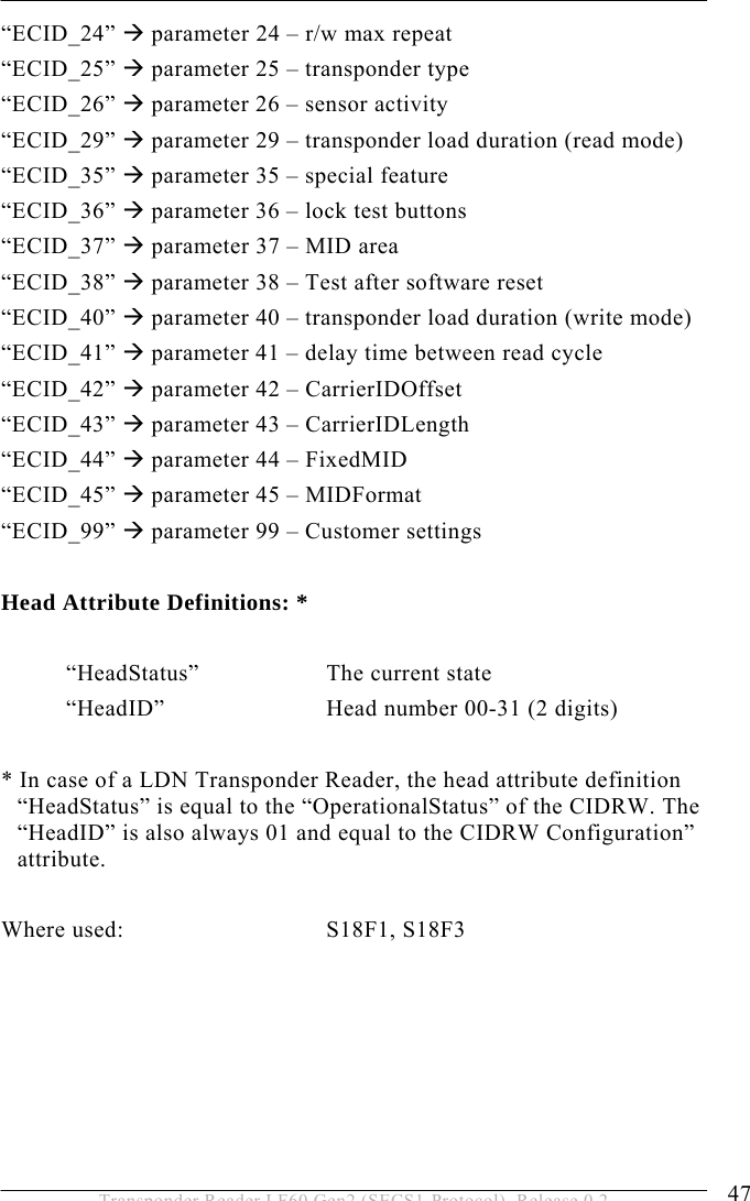
![5 OPERATION 46 Transponder Reader LF60 Gen2 (SECS1-Protocol), Release 0.2 ALTX[3] ‘:’ a colon separates the alarm text from the sensor states Where used: S5F1 ATTRID Format: A[max25] Description: Identifier for an attribute for a specific type of object. CIDRW Attribute Definitions: “Configuration” Number of heads “AlarmStatus” Current CIDRW sub state of ALARM STATUS “OperationalStatus” Current CIDRW sub state of OPERATIONAL “SoftwareRevisionLevel” Revision (version) of software - 8 byte maximum “CarrierIDOffset” Offset of CID in CID field (MID area) “CarrierIDLength” Length of CID in CID field (MID area) “ECID_00” Æ parameter 0 – Gateway ID (ECID=0) “ECID_01” Æ parameter 1 – Baudrate (ECID=1) “ECID_02” Æ parameter 2 – Inter-Character-Timeout T1 “ECID_03” Æ parameter 3 – Block-Protocol-Timeout T2 “ECID_04” Æ parameter 4 – Reply-Timeout T3 “ECID_05” Æ parameter 5 – Inter-Block-Timeout T4 “ECID_06” Æ parameter 6 – Retry-Limit RTY “ECID_07” Æ parameter 7 – TARGETID high Byte “ECID_08” Æ parameter 8 – TARGETID low Byte “ECID_09” Æ parameter 9 – Heartbeat time “ECID_10” Æ parameter 10 – FIX “ECID_11” Æ parameter 11 – Reader ID “ECID_12” Æ parameter 12 – HeadID “ECID_13” Æ parameter 13 – Antenna tuning “ECID_23” Æ parameter 23 – triggered read frequency](https://usermanual.wiki/Brooks-Automation/LF60/User-Guide-948419-Page-46.png)
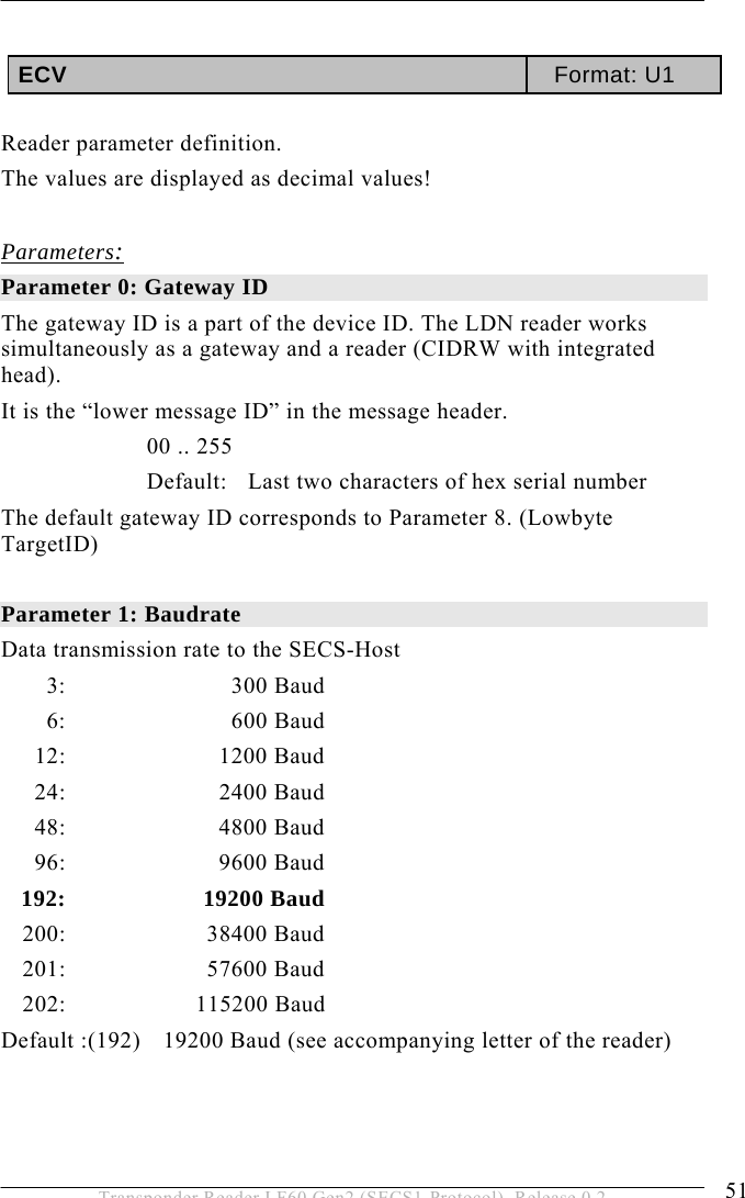
![5 OPERATION 48 Transponder Reader LF60 Gen2 (SECS1-Protocol), Release 0.2 ATTRVAL Format: A[max4] Description: Value of the specified attribute. CIDRW Attribute Definitions: “Configuration” Number of heads “01” “AlarmStatus” Current CIDRW sub state of ALARM STATUS “0” … NO “1” … ALARMS “OperationalStatus” Current CIDRW sub state of OPERATIONAL “IDLE” … reader in IDLE mode “BUSY” … reader is busy “MANT” … maintenance mode “SoftwareRevisionLevel” Revision (version) of Software – 8 byte maximum ECID_00 to ECID_45 see data item ECV parameter 0 to parameter 45 Head Attribute Definitions: “HeadStatus” The current state “IDLE” … reader in IDLE mode “BUSY” … reader is busy “NOOP”… not operating “HeadID” Head number 0-31 (2 digits) “00” … Reader 0 “31” … Reader 31 Where used: S18F1, S18F3](https://usermanual.wiki/Brooks-Automation/LF60/User-Guide-948419-Page-48.png)
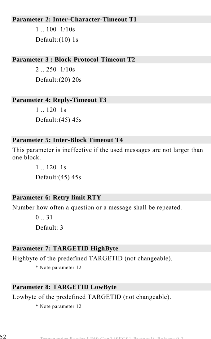
![OPERATION 5 49 Transponder Reader LF60 Gen2 (SECS1-Protocol), Release 0.2 CPVAL Format: A[max2] Description: State request value “OP” … operating state “MT” … maintenance state Where used: S18F13 DATA Format: A Description: A vector or string of unformatted data Multipage transponder: DATA area depends on the MID area, can be page 1 – page 17 Read/write transponder: DATA correspond to 8 byte MID Read/only transponder: DATA correspond to 8 byte MID Where used: S18F6, S18F7 DATALENGTH Format: U2 Description: Total bytes to be sent. The DATALENGTH corresponds to the quantity of bytes that should be read or written. The valid range depends on the length of the MID area (parameter 37). Where used: S18F5, S18F7](https://usermanual.wiki/Brooks-Automation/LF60/User-Guide-948419-Page-49.png)
![5 OPERATION 50 Transponder Reader LF60 Gen2 (SECS1-Protocol), Release 0.2 DATASEG Format:A[2] Description: Used to identify the data requested. The DATASEG corresponds to the page number (PAGEID) of multipage, read/only and read/write transponders “00”: First page of any type of transponder or first page of the DATA area in case of a multipage transponder. Multipage-transponder (page 1 to page 17) : Start the reading or writing on the following page of a multipage transponder: “01”: page 1 “81”: Locked page 1 ... ... “11”: page 17 “91”: Locked page 17 Read/only transponder: “F0”: Read only the one page Read/write transponder: “F1”: Read or write only the one page Where used: S18F5, S18F7 EAC Format: B[1] Acknowledge code for new reader constant 0: Parameter was set successfully 1: Parameter could not be set Where used: S2F16 ECID Format: U1 Parameter number of reader (see data item ECV) Where used: S2F13, S2F15](https://usermanual.wiki/Brooks-Automation/LF60/User-Guide-948419-Page-50.png)
![OPERATION 5 61 Transponder Reader LF60 Gen2 (SECS1-Protocol), Release 0.2 Parameter 45 = ‘1’ or ‘2’: tag memory: Page 2 0 0 0 0 1 2 3 4 Memory address 15 14 13 12 11 10 9 8 Page 1 5 6 7 8 9 A B C Memory address 7 6 5 4 3 2 1 0 Æ Output string (parameter 45 = ‘1’): ‘0000123456789ABC’ Æ Output string (parameter 45 = ‘2’): ‘123456789ABC’ Default: 0 Parameter 99: custom code If the customer requires special parameter settings that deviate from the default values, a customer code can be assigned by BROOKS to set several parameter values via one parameter. The following parameters are defined: ‘00’ set the following parameters: Reader is compliant to last revisions of SEMI E99-0303 ‘03’ set the following parameter: Reader is compliant to older reader versions before the revision of SEMI E99-0303. MDLN Format: A[6] Equipment model number. Where used: S1F2 Parameter Value 37 2 42 0 43 16 44 1 45 0 Parameter Value 37 1 42 0 43 8 44 0 45 0](https://usermanual.wiki/Brooks-Automation/LF60/User-Guide-948419-Page-61.png)
![5 OPERATION 62 Transponder Reader LF60 Gen2 (SECS1-Protocol), Release 0.2 MF Format: B[1] Material format code. 20: The material port number corresponds to the sensor number and state Where used: S3F5, S3F7 MHEAD Format: B[10] SECS message block header associated with message block in error. Where used: S9F1, S9F3, S9F5, S9F7, S9F9 MID Format: A Description: Material ID Depending on the type of transponder, it is possible to modify the MID. Multipage transponder: MID can be set from “0” (no MID) to “10” (MID occupies the first 10 pages (writeable)) Read/write transponder: MID corresponds to DATA (writeable) Read/only transponder : MID corresponds to DATA (fix) ) Pay attention to parameter 42 – 45. Where used: S18F10, S18F11](https://usermanual.wiki/Brooks-Automation/LF60/User-Guide-948419-Page-62.png)
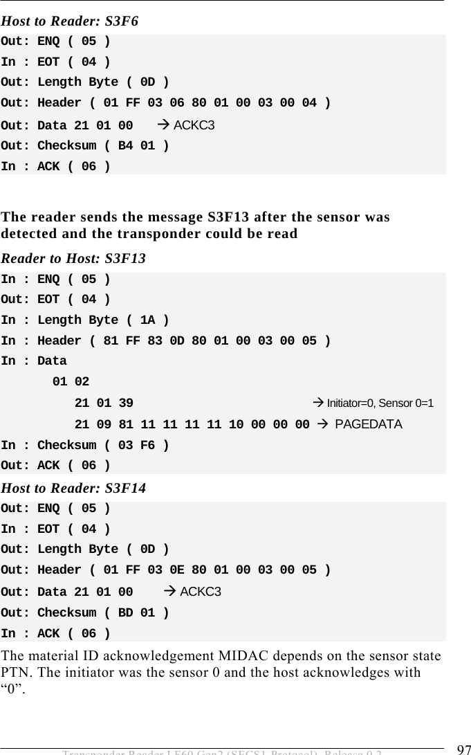
![OPERATION 5 63 Transponder Reader LF60 Gen2 (SECS1-Protocol), Release 0.2 MIDAC Format: B[1] Material ID acknowledge code 0 Material ID acknowledged; the presence sensor was the initiator 1 Not defined 2 Material ID acknowledged - reaction on externally triggered action; the message cannot be related to any sensor >2 Material ID not acknowledged The data item port number PTN indicates the initiator. Where used: S3F14, S3F68 MIDRA Format: B[1] Material ID acknowledge code 2 Acknowledge, will send MID later in S3F13 Where used: S3F12 OFLACK Format: B[1] Acknowledge code for OFF-LINE request. 0 OFF-LINE acknowledge (reader is offline) Where used: S1F16](https://usermanual.wiki/Brooks-Automation/LF60/User-Guide-948419-Page-63.png)
![5 OPERATION 64 Transponder Reader LF60 Gen2 (SECS1-Protocol), Release 0.2 ONLACK Format: B[1] Acknowledge code for ON-LINE request. 0 ON-LINE accepted (reader is online) Where used: S1F18 PAGE_ID Format: B[1] Page number of multipage, read/only and read/write transponders 0x00 : First page of the data area of a multipage Transponder. Multipage transponder (page 1 up to page 17) : If only one page of the multipage transponder is read, note the following: 0x01 : (1) page 1 0x81 : (129) locked page 1 ... ... 0x11 : (17) page 17 0x91 : (146) locked page 17 Read/only transponder : 0xF0 : (240) Read one page only Read/write transponder: 0xF1 : (241) Read or write one page only Where used: S3F11](https://usermanual.wiki/Brooks-Automation/LF60/User-Guide-948419-Page-64.png)
![OPERATION 5 65 Transponder Reader LF60 Gen2 (SECS1-Protocol), Release 0.2 PAGEDATA Format: B[9] The cassette identifier that has been read or will be written. The PAGEDATA corresponds to the value of a transponder page. PAGEDATA [0] Corresponds to the page number. The value of the page number is displayed in the data item “PAGE_ID”. PAGEDATA [1] The 8 byte (one page) of the transponder ID are following. PAGEDATA [8] Where used: S3F7, S3F12, S3F13, S3F65 PM Information Format: A[2] Description: Preventive maintenance information “NE” … Normal execution “MR” … Maintenance required Where used: S18F2, S18F4, S18F8, S18F10, S18F12, S18F14 PTN Format: B[1] Information about the state of up to two sensors and the initiator of the message. The second sensor is not implemented yet! For special applications, the reading process of the transponder reader is triggered by two sensors. In this case, it is necessary to distinguish between the two sensors. The initiator represents the number of the sensor which has caused the message. Default: only sensor 0 is defined! bit 7 ........ bit 0 Initiator Sensor 1 Sensor 0 ......](https://usermanual.wiki/Brooks-Automation/LF60/User-Guide-948419-Page-65.png)
![5 OPERATION 66 Transponder Reader LF60 Gen2 (SECS1-Protocol), Release 0.2 Sensor 0: bit0 – bit2 The current state of sensor 0 is described in three bits 0 Sensor not occupied 1 Sensor occupied 7 Sensor not defined Sensor 1: bit3 – bit5 (defined for future developments) The current state of sensor 1 is described in three bits 0 Sensor not occupied 1 Sensor occupied 7 Sensor not defined Initiator: bit6 – bit7 The initiator represents the number of the sensor that has caused the message. 0 Sensor 0 1 Sensor 1 (not implemented yet) 3 Cannot be assigned Where used: S3F5, S3F7, S3F12, S3F13, S3F67 RAC Format: B[1] Reset acknowledge code. 0 Reset to be done 1 Reset could not be done Where used: S2F20](https://usermanual.wiki/Brooks-Automation/LF60/User-Guide-948419-Page-66.png)
![OPERATION 5 67 Transponder Reader LF60 Gen2 (SECS1-Protocol), Release 0.2 RIC Format: B[1] Reset code. 1 Power up reset 2 Software reset Where used: S2F19 SHEAD Format: B[10] Stored SECS message block header. Only the last message is stored, which must still be confirmed by the host! Where used: S9F9 SOFTREV Format:A[6] Software revision code. Where used: S1F2 SSACK Format: A[2] Description: Result information on the status of the request concerning the service request. “NO” … Normal operation Indicates the success of the requested action “EE” … Execute error Cannot read Tag data . Cannot read ID sequence. But equipment is normal. “CE” … Communication error](https://usermanual.wiki/Brooks-Automation/LF60/User-Guide-948419-Page-67.png)
![5 OPERATION 68 Transponder Reader LF60 Gen2 (SECS1-Protocol), Release 0.2 Syntax error of Message or Message format or value. “HE” … Hardware error ID reader/writer head fault, ID reader/writer head is powered off. “TE” … Tag error Where used: S18F2, S18F4, S18F6, S18F8, S18F10, S18F12, S18F14 SSCMD Format: A[max18] Description: Indicates an action to be performed by the subsystem. Used to differentiate between the different subsystem commands indicated. “ChangeState” … Change state “GetStatus” … Get state “PerformDiagnostics” … Perform diagnostics “Reset” … Reset CIDRW Where used: S18F13](https://usermanual.wiki/Brooks-Automation/LF60/User-Guide-948419-Page-68.png)
![OPERATION 5 69 Transponder Reader LF60 Gen2 (SECS1-Protocol), Release 0.2 STATUS Format: A[2] Description: Provides status information of a subsystem component. Consists of PM Information and the current values of the CIDRW attributes AlarmStatus, OperationalStatus, and HeadStatus. List of a Status L,4 <PMInformation> <AlarmStatus> <OperationalStatus> <HeadStatus> For data items OperationalStatus and HeadStatus see data item ATTRVAL. Where used: S18F2, S18F4, S18F8, S18F10, S18F12, S18F14](https://usermanual.wiki/Brooks-Automation/LF60/User-Guide-948419-Page-69.png)
![5 OPERATION 70 Transponder Reader LF60 Gen2 (SECS1-Protocol), Release 0.2 TARGETID Format: A[max4] Description: Identifies where a request for action or data is to be applied. The TARGETID corresponds to the last four characters of the serial number on a label on the reader. Alternatively, you can use the HeadID. See also reader parameter definitions (data item ECV) parameter 7, 8 and 12. Example : “00-xxxx-LDN” (xxxx … dependent on the individual reader) The 4 ASCII character TARGETID xxxx is set by delivery. The predefined TARGETID is fixed and cannot be changed. The 2 ASCII character HeadID is changeable and defined in parameter 12 (‘ECID_12’). Where used: S18F1, S18F3, S18F5, S18F7, S18F9, S18F11, S18F13](https://usermanual.wiki/Brooks-Automation/LF60/User-Guide-948419-Page-70.png)
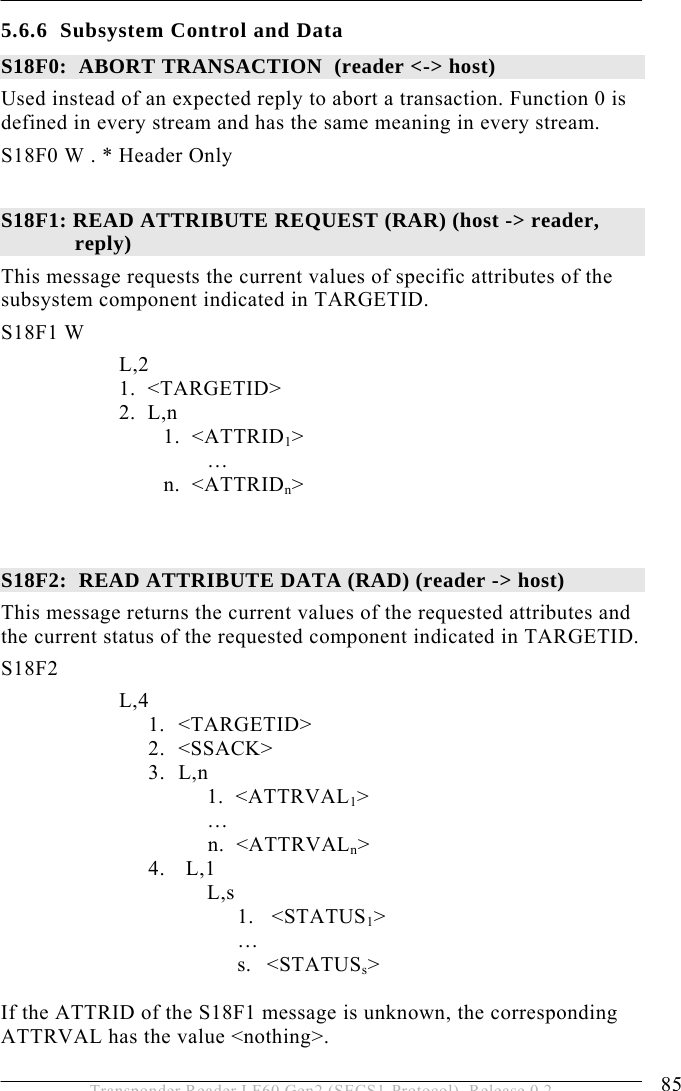
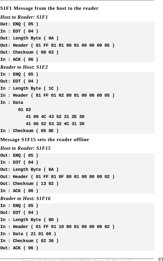
![OPERATION 5 75 Transponder Reader LF60 Gen2 (SECS1-Protocol), Release 0.2 5.6 Message Details 5.6.1 Equipment status S1F0: ABORT TRANSACTION (reader <-> host) Used instead of an expected reply to abort a transaction. Function 0 is defined in every stream and has the same meaning in every stream. S1F0 W . * Header Only S1F1: ARE YOU THERE REQUEST (reader <-> host, reply) Establishes if the gateway or host is online. S1F1 W . * Header Only S1F2: ON-LINE DATA (host -> reader) The host signifies that it is online. S1F2 <L[2] <A[6] MDLN > <A[6] SOFTREV > >. S1F2: ON-LINE (reader -> host) The reader signifies that it is online. S1F2 <L[2] <A[6] MDLN > <A[6] SOFTREV > >. S1F15: REQUEST OFF_LINE (host ->reader, reply) The reader is requested to change the communication state to offline. The reader can only be set online again by using message S1F17 (or reset S2F19), all other messages will be aborted by the SxF0 message! S1F15 W. *Header Only](https://usermanual.wiki/Brooks-Automation/LF60/User-Guide-948419-Page-75.png)
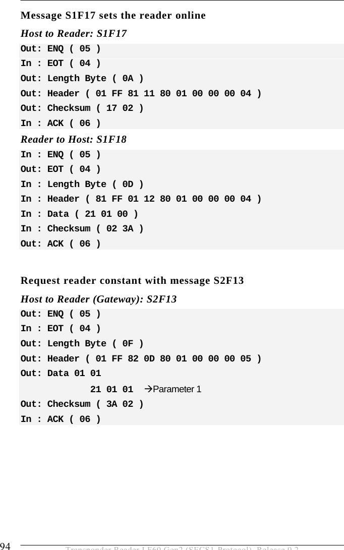
![5 OPERATION 76 Transponder Reader LF60 Gen2 (SECS1-Protocol), Release 0.2 S1F16: OFFLINE ACKNOWLEDGE (reader -> host) Acknowledge. S1F16 <B[1] OFLACK>. S1F17: REQUEST ON_LINE (host ->reader, reply) The reader is requested to change the communication state to online. S1F17 W. *Header Only S1F18: ONLINE ACKNOWLEDGE (reader -> host) Acknowledge. S1F18 <B[1] ONLACK>. 5.6.2 Equipment Control S2F0: ABORT TRANSACTION (reader <-> host) Used instead of an expected reply to abort a transaction. Function 0 is defined in every stream and has the same meaning in every stream. S2F0 W . * Header Only S2F13: EQUIPMENT CONSTANT REQUEST (host-> reader, reply) The host requests one constant from the gateway or reader. S2F13 W <L[1] <U1[1] ECID> >.](https://usermanual.wiki/Brooks-Automation/LF60/User-Guide-948419-Page-76.png)
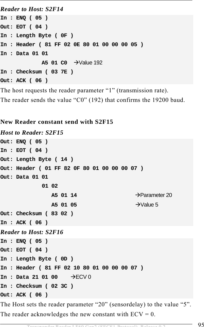
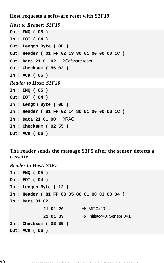
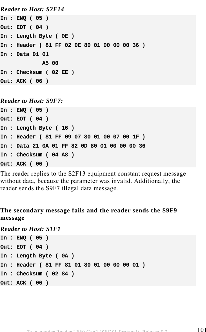
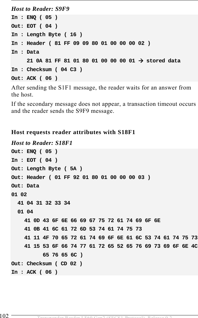
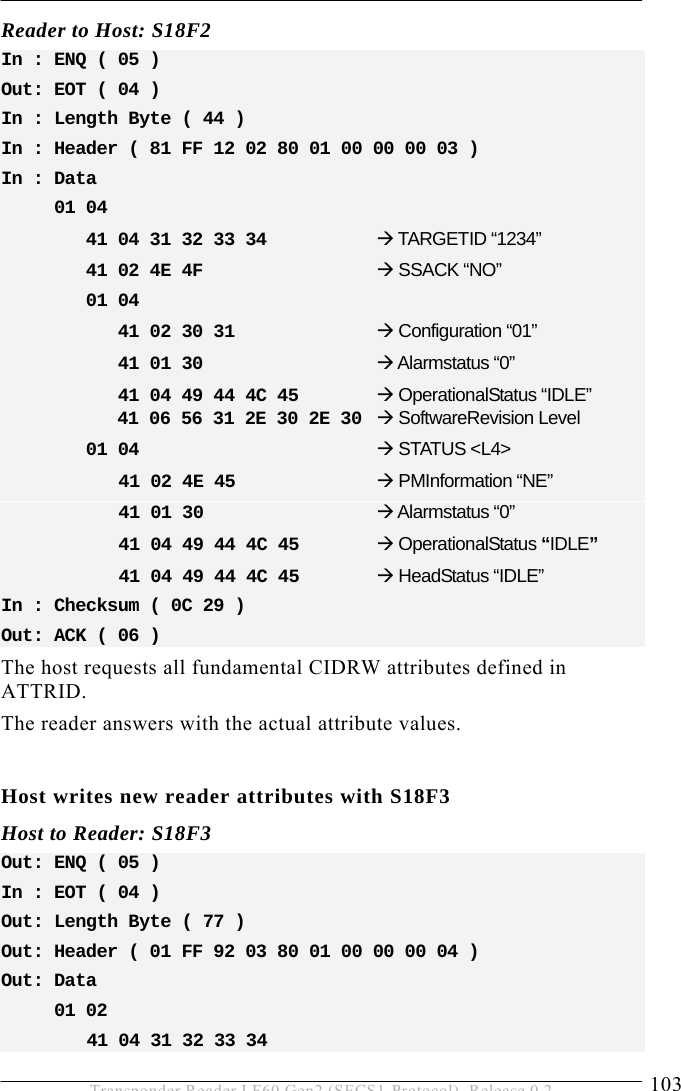
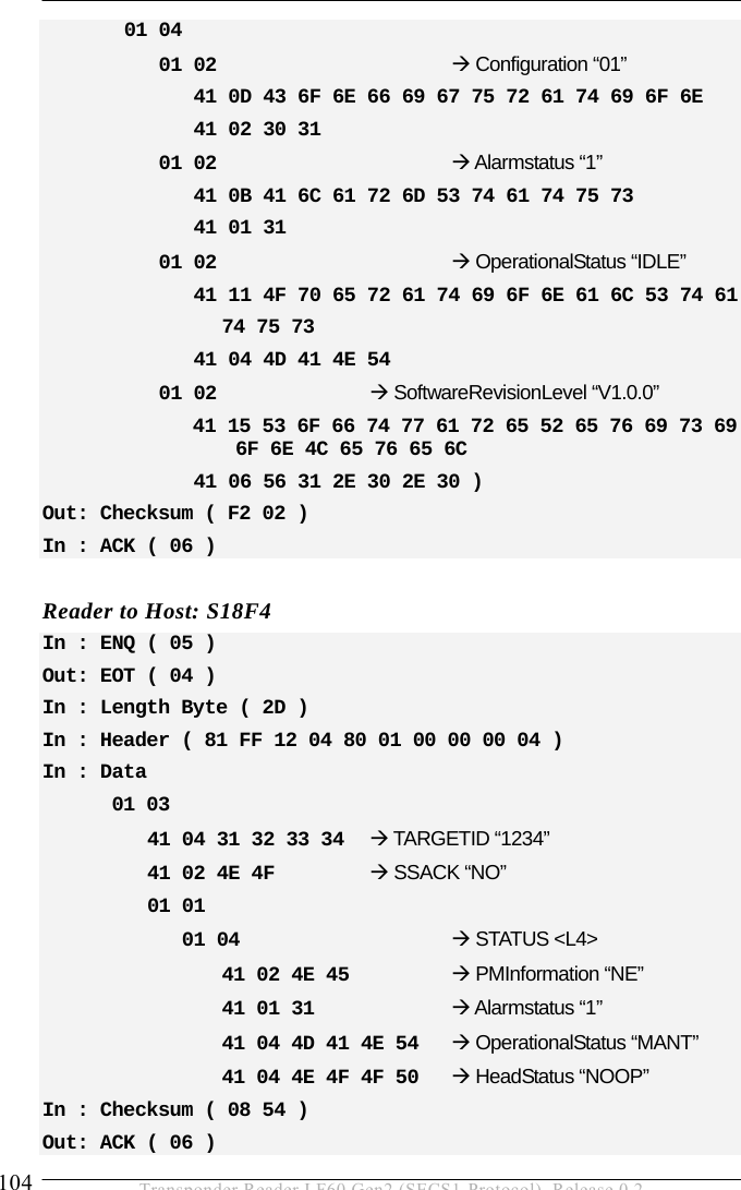
![OPERATION 5 77 Transponder Reader LF60 Gen2 (SECS1-Protocol), Release 0.2 S2F14: EQUIPMENT CONSTANT DATA (reader -> host) The reader sends the requested constant to the host. S2F14 <L[1] <U1[1] ECV> >. S2F15: NEW EQUIPMENT CONSTANT SEND (host-> reader, reply) The host changes one reader constant. S2F15 W <L[1] <L[2] <U1[1] ECID> <U1[1] ECV> > >. S2F16: NEW EQUIPMENT CONSTANT ACKNOWLEDGE (reader -> host) The reader acknowledges the setting of the reader constant. S2F16 <B[1] EAC>. S2F19: RESET SEND (host -> reader, reply) The host requests the reader to reset the hardware and software. If a heartbeat time is set (parameter 9) the reader sends a S1F1 message when the reset was finished. The power up reset requires a few seconds. S2F19 W <B[1] RIC>.](https://usermanual.wiki/Brooks-Automation/LF60/User-Guide-948419-Page-77.png)
![5 OPERATION 78 Transponder Reader LF60 Gen2 (SECS1-Protocol), Release 0.2 S2F20: RESET ACKNOWLEDGE (reader -> host) The reader acknowledges the reset. In case of a power up reset, the S2F20 message requires a few seconds. S2F20 <B[1] RAC>. 5.6.3 Material Status S3F0: ABORT TRANSACTION (reader <-> host) Used instead of an expected reply to abort a transaction. Function 0 is defined in every stream and has the same meaning in every stream. S3F0 W . * Header Only S3F5: CASSETTE FOUND SEND (reader -> host, reply) The reader sends the information that a cassette was detected by the presence sensor. This message will be sent only if a sensor is connected and activated (see parameters 27 ‘watchport’ and 26 ‘sensor activity’). S3F5 W. <L[2] <B[1] MF> <B[1] PTN> >. S3F6: CASSETTE FOUND ACKNOWLEDGE (host -> reader) The host acknowledges the cassette found message. S3F6 <B[1] ACKC3>.](https://usermanual.wiki/Brooks-Automation/LF60/User-Guide-948419-Page-78.png)
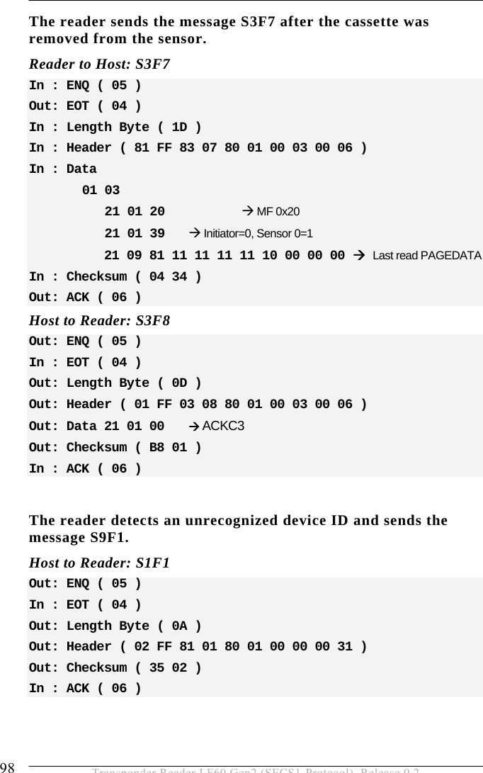
![OPERATION 5 79 Transponder Reader LF60 Gen2 (SECS1-Protocol), Release 0.2 S3F7: CASSETTE LOST SEND (reader -> host, reply) The reader sends the information that the cassette was removed from the I/O port (presence sensor). This message will be sent only if a sensor is connected and activated (see parameters 27 ‘watchport’ and 26 ‘sensor activity’). The PAGEDATA can be given only if the PAGEDATA that was read at last is still known. S3F7 W. <L[3] <B[1] MF > <B[1] PTN > <B[9] PAGEDATA >* >. * a zero-length PAGEDATA indicates that no PAGEDATA is available (case of error) S3F8: CASSETTE LOST ACKNOWLEDGE (host -> reader) The host acknowledges the cassette lost message. S3F8 <B[1] ACKC3>. S3F11: READ MID AT I/O PORT (host -> reader, reply) The host requests the reader to read the PAGEDATA of the given PAGE_ID. S3F11 W <B[1] PAGE_ID>.](https://usermanual.wiki/Brooks-Automation/LF60/User-Guide-948419-Page-79.png)
![5 OPERATION 80 Transponder Reader LF60 Gen2 (SECS1-Protocol), Release 0.2 S3F12: READ ACKNOWLEDGE (reader -> host) The reader only acknowledges the receipt of the reading command. The PAGEDATA will be sent later! S3F12 <L[3] <B[1] PTN>* <B[1] MIDRA> <B[9] PAGEDATA>** >. * a zero-length PTN indicates that no PTN is available ** a zero-length PAGEDATA indicates that no DATA is available S3F13: RETURN READ MID (reader -> host, reply) The reader sends the ID of the cassette at the I/O port to the host. S3F13 W <L[2] <B[1] PTN> <B[9] PAGEDATA > >. S3F14: MID ACKNOWLEDGE (host -> reader) The host acknowledges the received data. S3F14 <B[1] MIDAC>. S3F65: WRITE MID AT I/O PORT (host -> reader, reply) The host requests that the reader write the PAGEDATA. S3F65 W <B[9] PAGEDATA >](https://usermanual.wiki/Brooks-Automation/LF60/User-Guide-948419-Page-80.png)
![OPERATION 5 81 Transponder Reader LF60 Gen2 (SECS1-Protocol), Release 0.2 S3F66: WRITE ACKNOWLEDGE (reader -> host) The reader only acknowledges the receipt of the write command. The write acknowledge will be sent later! S3F66 <L[2] <B[1] MIDRA> <B[9] PAGEDATA > >. S3F67: RETURN WRITE SUCCESS (reader -> host, reply) The reader reports the successful writing of the transponder. The reader sends information about the presence sensor. S3F67 W <B[1] PTN>. S3F68: WRITE SUCCESS ACKNOWLEDGE (host -> reader) The host acknowledges the received data. S3F68 <B[1] MIDAC>. S3F73: LOCK MID AT I/O PORT (host -> reader, reply) The host requests the reader to lock the requested page. S3F73 W <B[1] PAGE_ID>. Pay attention: Locking of a transponder page is permanent. You can not unlock a transponder page!](https://usermanual.wiki/Brooks-Automation/LF60/User-Guide-948419-Page-81.png)
![5 OPERATION 82 Transponder Reader LF60 Gen2 (SECS1-Protocol), Release 0.2 S3F74: LOCK ACKNOWLEDGE (reader -> host) The reader acknowledges the receipt of the locking command only. The locking acknowledgement will be sent later! S3F74 <L[2] <B[1] MIDRA> <B[9] PAGEDATA > >. S3F75: RETURN LOCK SUCCESS (reader -> host, reply) The reader reports the successful locking of the given page. The reader sends information about the presence sensor. S3F75 W <B[1] PTN>. S3F76: LOCK SUCCESS ACKNOWLEDGE (host -> reader) The host acknowledges the receipt of the lock success message (S3F75). S3F76 <B[1] MIDAC>.](https://usermanual.wiki/Brooks-Automation/LF60/User-Guide-948419-Page-82.png)
![OPERATION 5 83 Transponder Reader LF60 Gen2 (SECS1-Protocol), Release 0.2 5.6.4 Exception Handling S5F0: ABORT TRANSACTION (reader <-> host) Used instead of an expected reply to abort a transaction. Function 0 is defined in every stream and has the same meaning in every stream. S5F0 W . * Header Only S5F1: GATEWAY READER ALARM REPORT SEND (reader -> host, reply) The reader reports all errors to the host. S5F1 W <L[3] <B[1] ALCD > * alarm code byte <B[1] ALID > * alarm ID <A[MAX 40] ALTX > * alarm text >. S5F2: ALARM REPORT ACKNOWLEDGE (host-> reader) The host acknowledges an alarm. S5F2 <B[1] ACKC5>.](https://usermanual.wiki/Brooks-Automation/LF60/User-Guide-948419-Page-83.png)
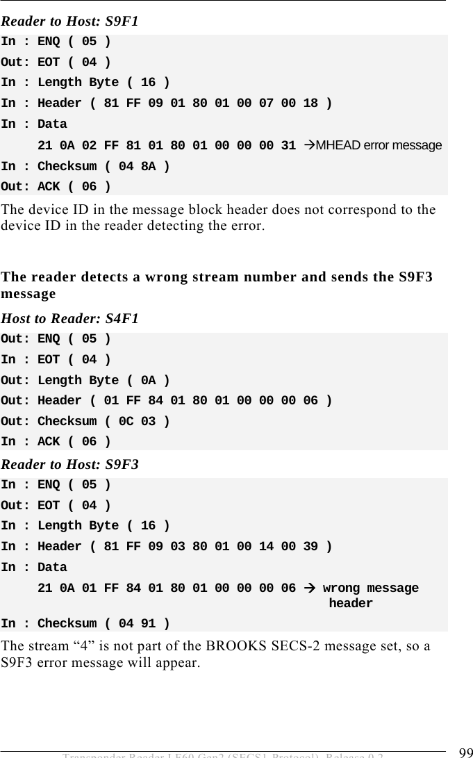
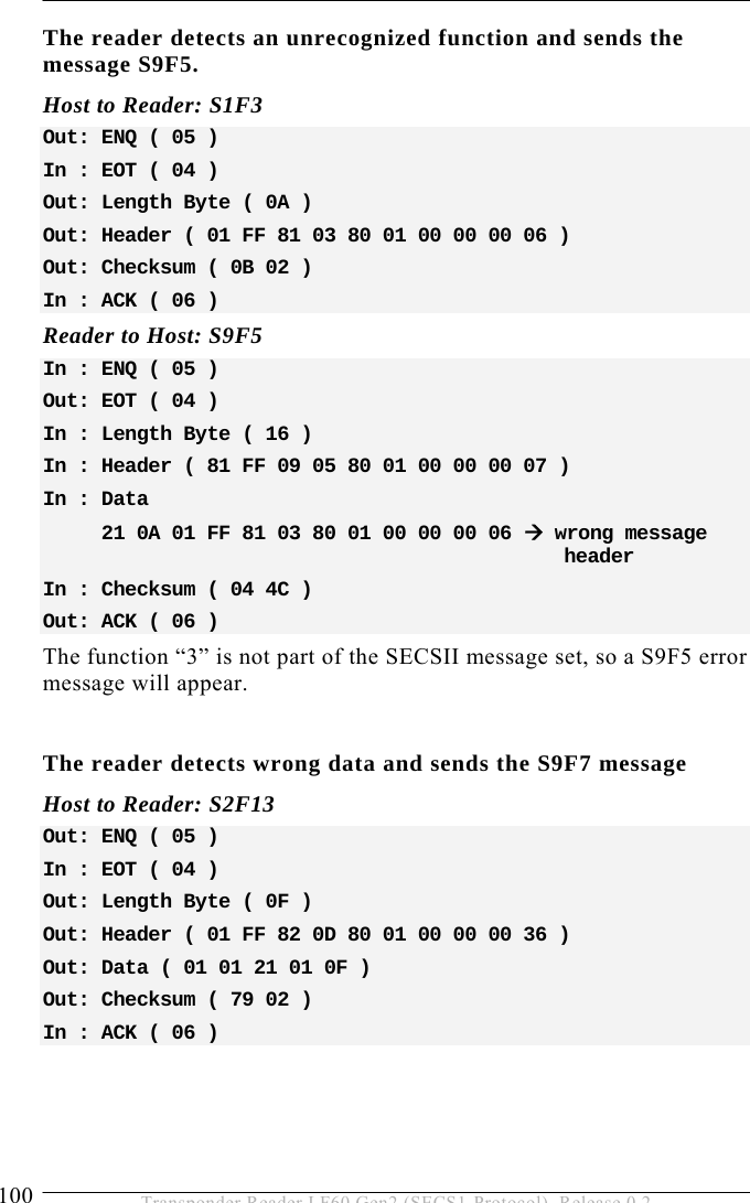
![5 OPERATION 84 Transponder Reader LF60 Gen2 (SECS1-Protocol), Release 0.2 5.6.5 System Errors S9F1: UNRECOGNIZED DEVICE ID (reader -> host) The device ID in the message block header does not correspond to the equipment device ID. S9F1 <B[10] MHEAD >. S9F3: UNRECOGNIZED STREAM TYPE (reader -> host) The reader does not recognize the stream type in the message block header. S9F3 <B[10] MHEAD >. S9F5: UNRECOGNIZED FUNCTION TYPE (reader -> host) The reader does not recognize the function number in the message block header. S9F5 <B[10] MHEAD >. S9F7: ILLEGAL DATA (reader -> host) The reader does not recognize the data in the message block header. S9F5 <B[10] MHEAD > . S9F9: TRANSACTION TIMER TIME-OUT (reader -> host) This message indicates that a transaction timer has timed out and that the corresponding transaction was aborted. Only the last sent message (which must be confirmed by the host) is stored and controlled. S9F9 <B[10] SHEAD > .](https://usermanual.wiki/Brooks-Automation/LF60/User-Guide-948419-Page-84.png)