Brooks Automation LF80BC1 LF80 Low Frequency RFID reader User Manual ZenID HSMS
Brooks Automation Inc. LF80 Low Frequency RFID reader ZenID HSMS
UserManual.wiki
>
Brooks Automation
>
LF80BC1 User Manual
User manual
Navigation menu
Upload a User Manual
Namespaces
Wiki Guide
HTML
PDF
Info
Views
User Manual
Discussion / Help
Navigation


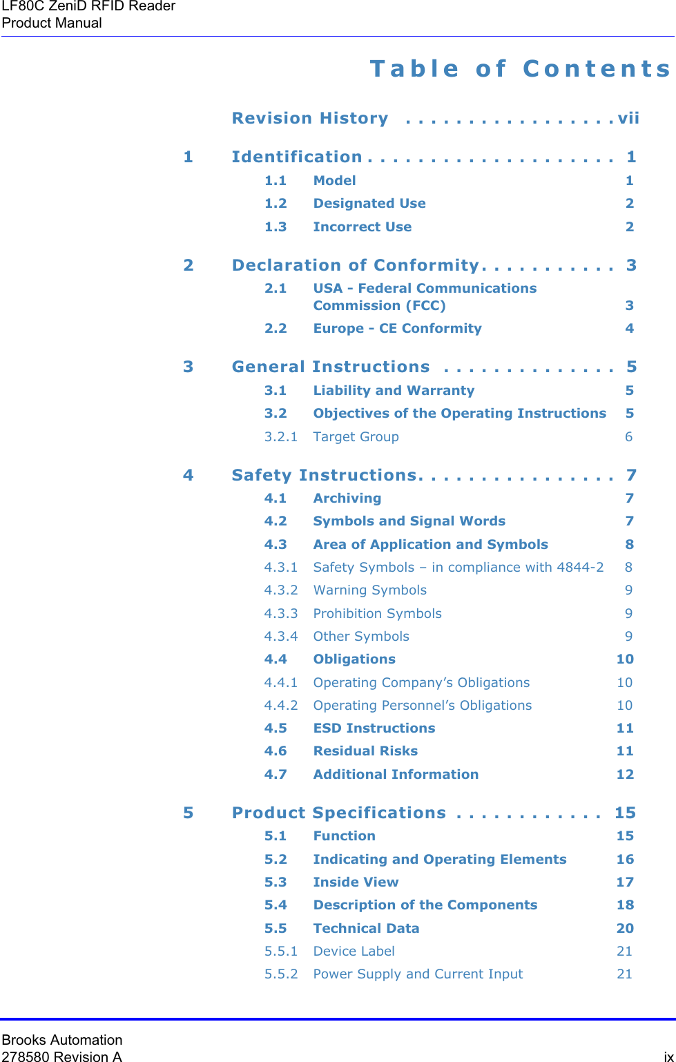

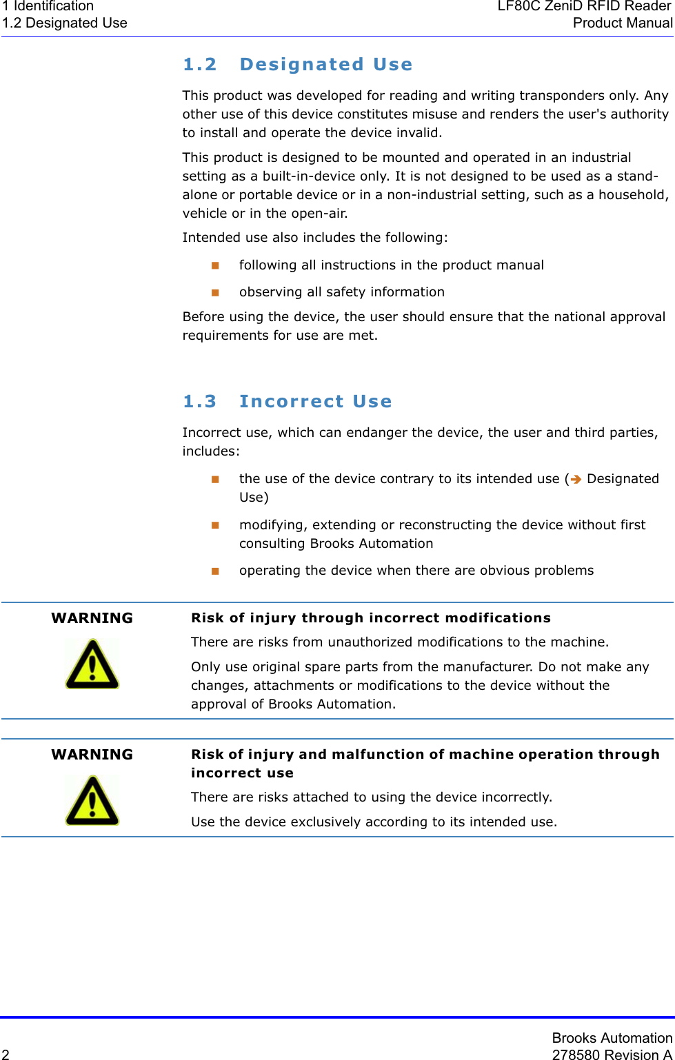
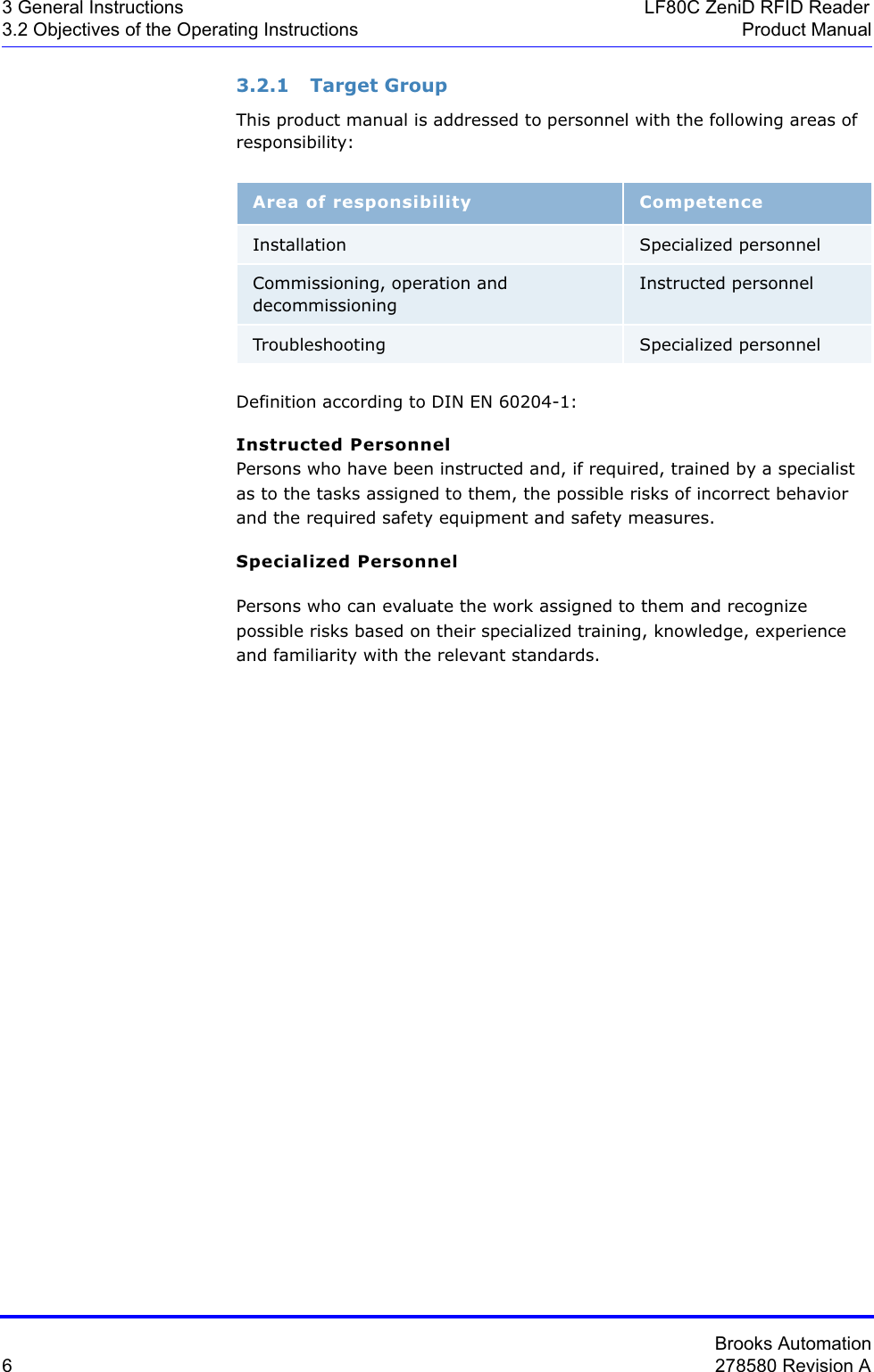


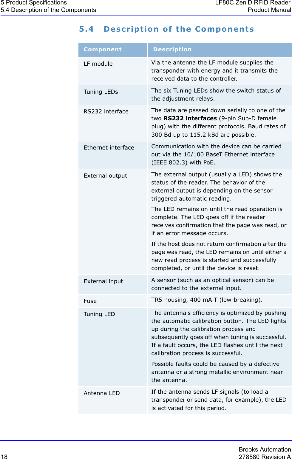


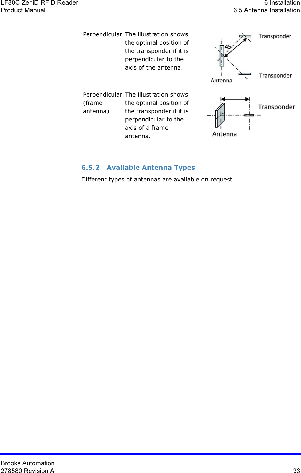
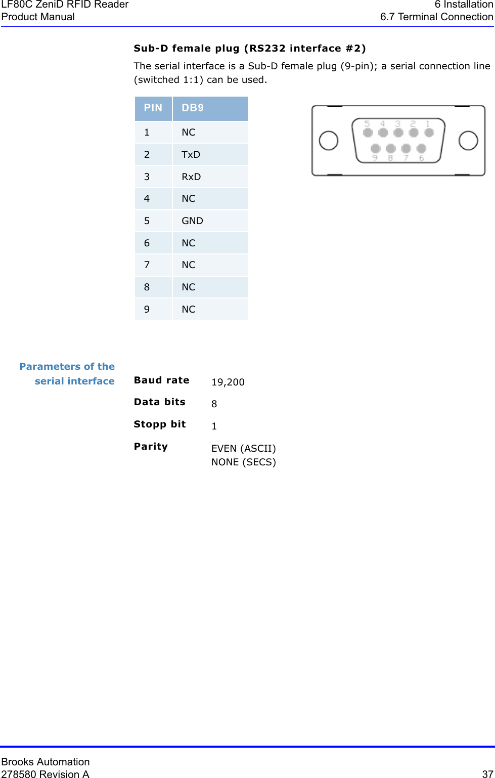
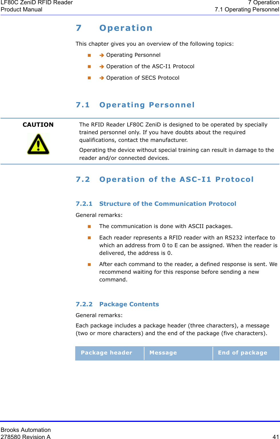

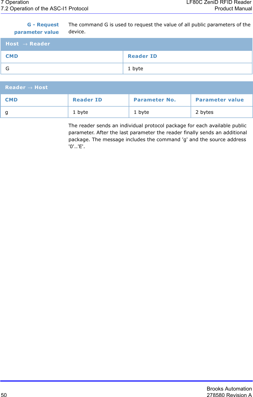
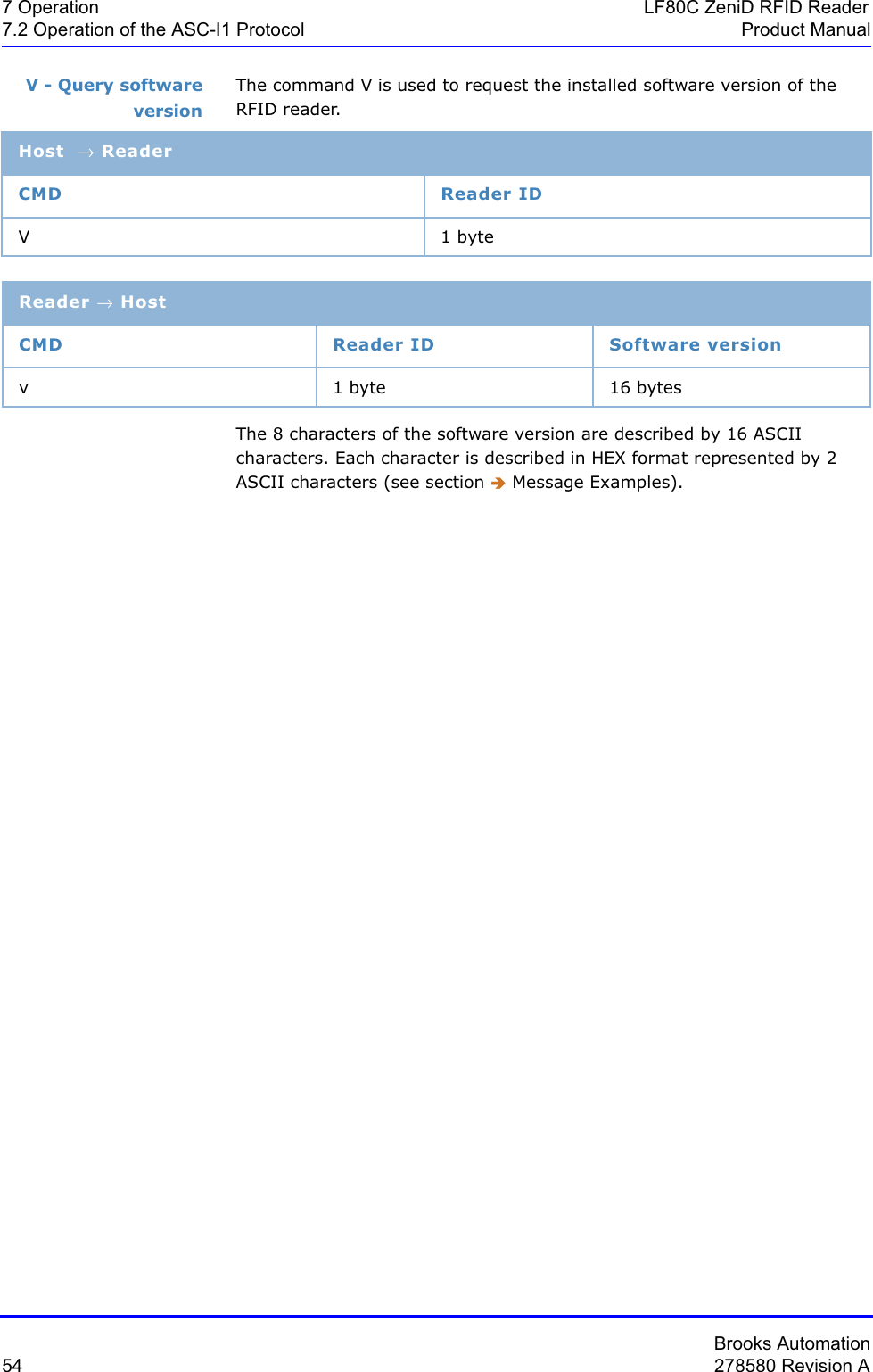
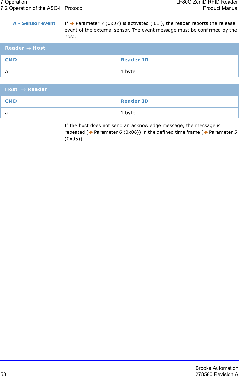
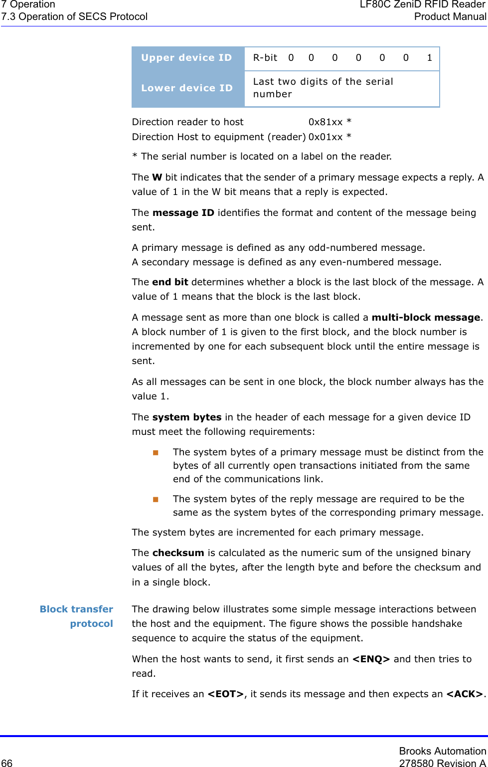
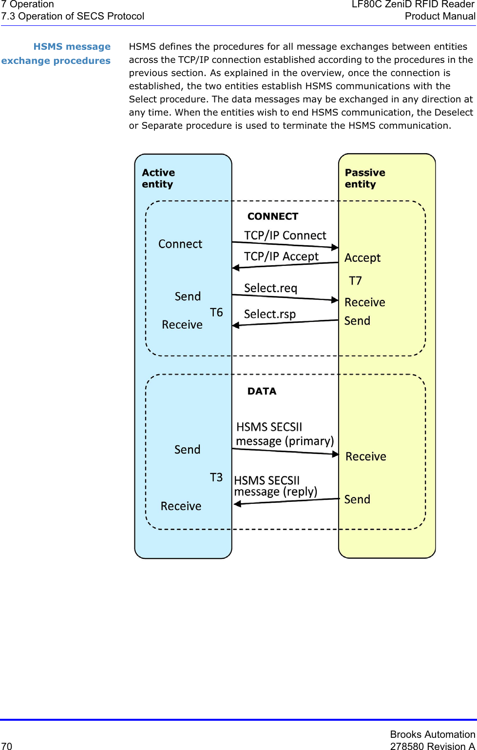
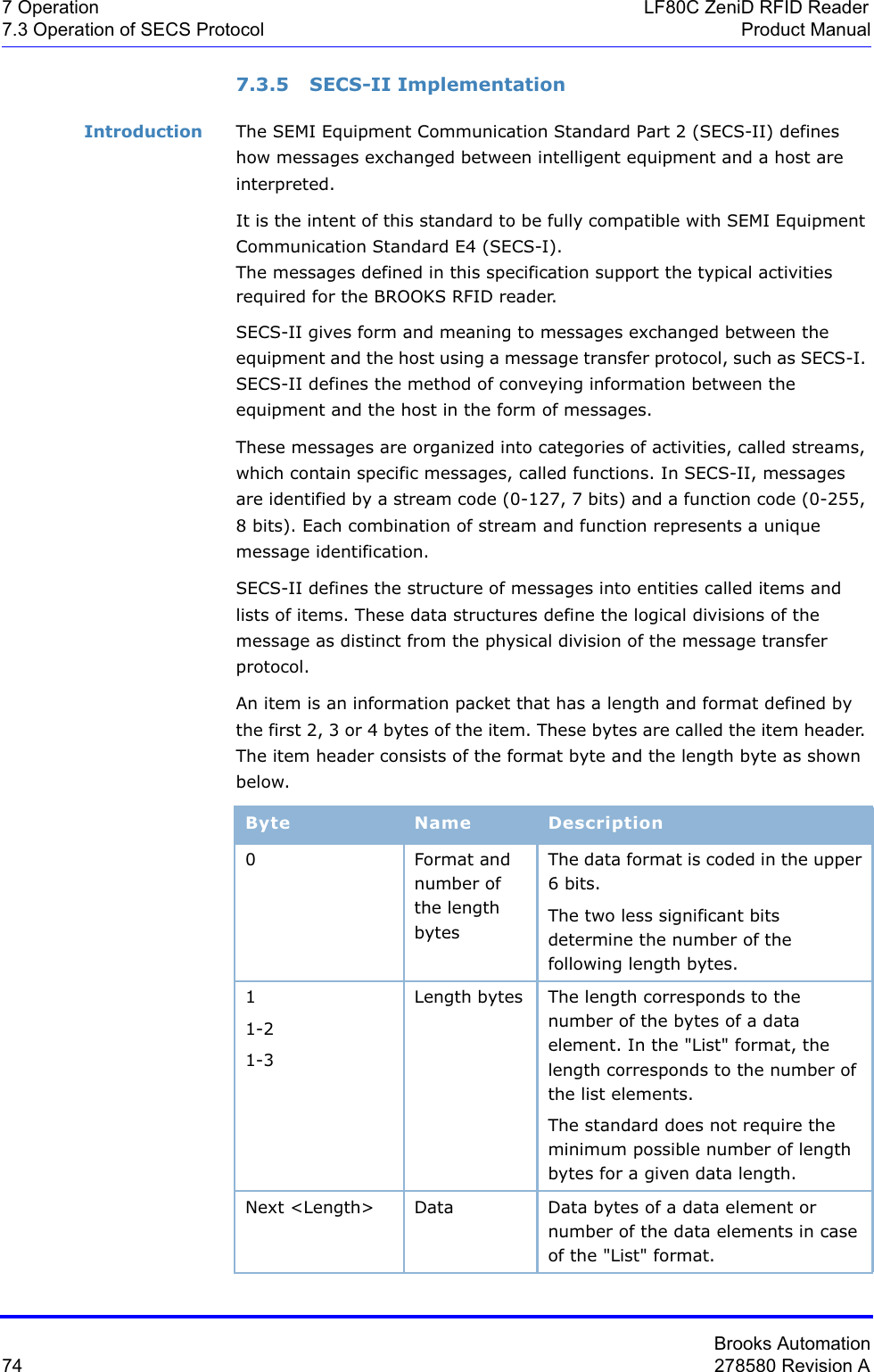
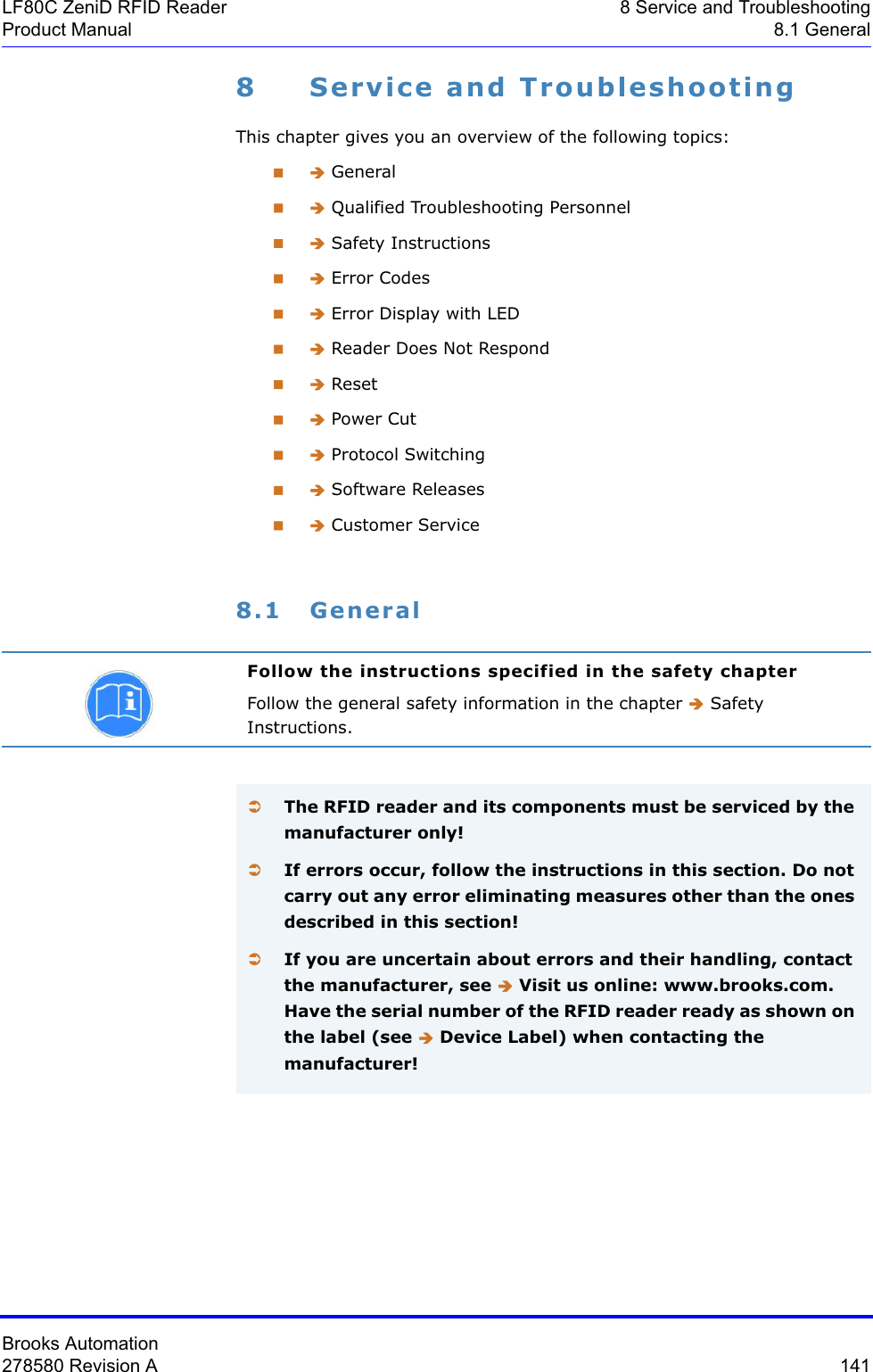
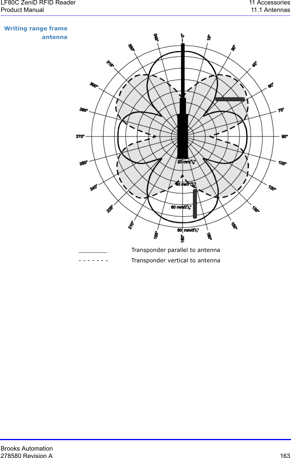
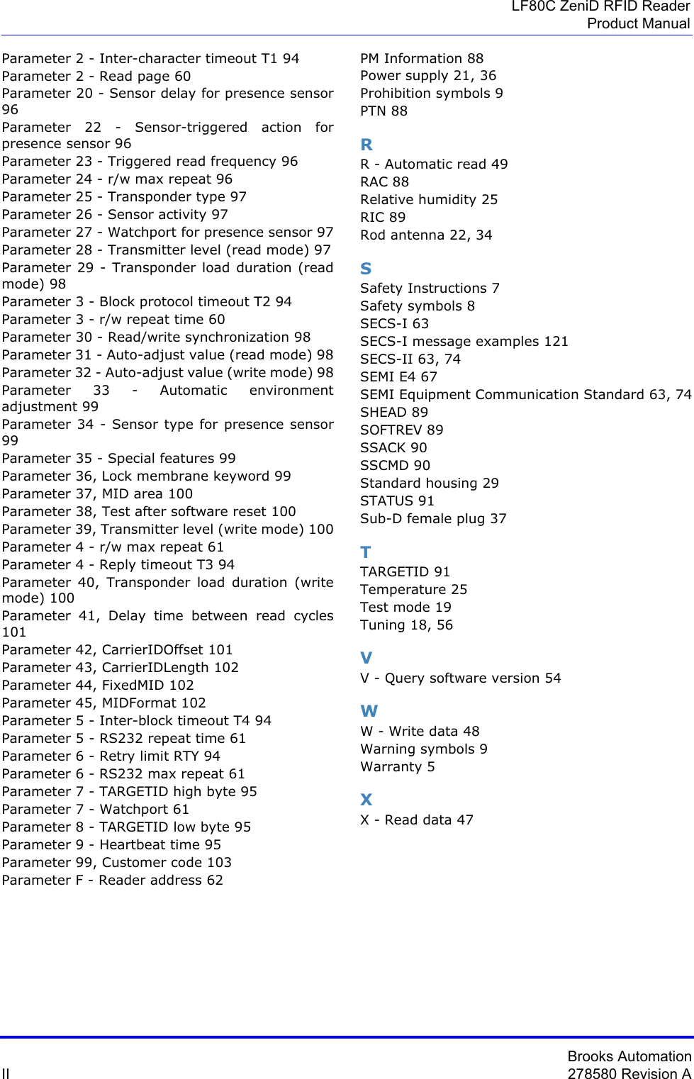
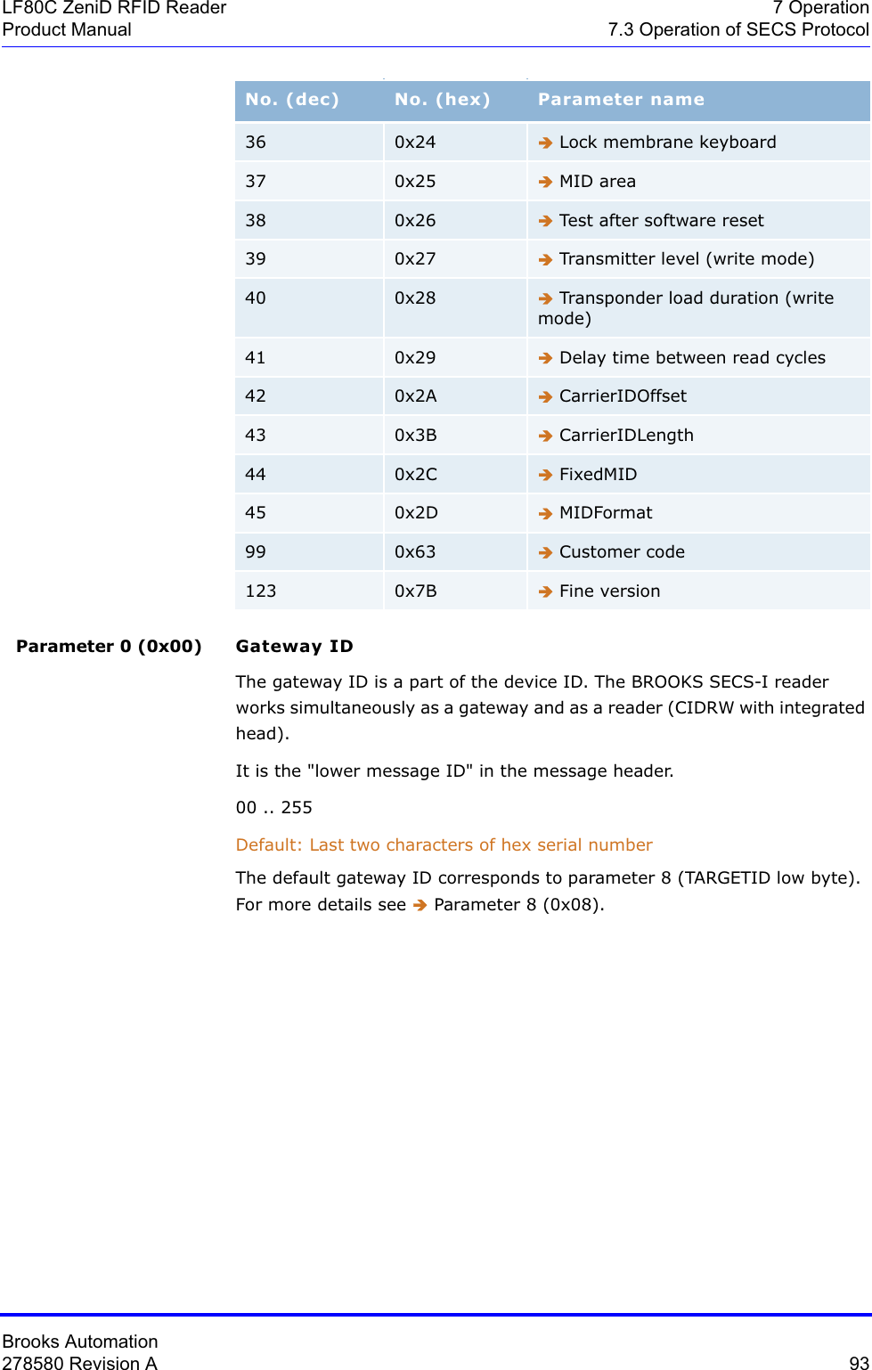
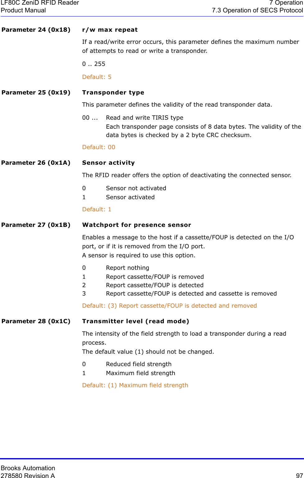
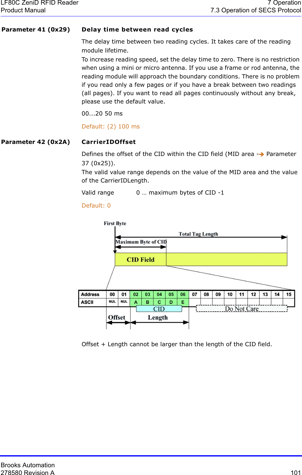
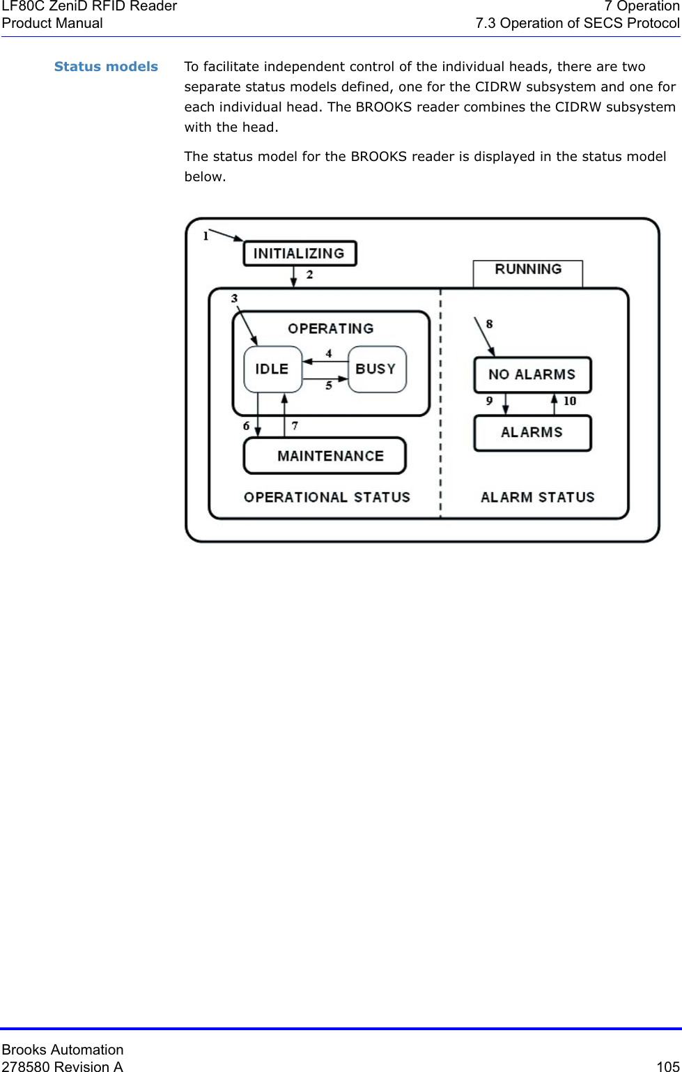
![Brooks Automation278580 Revision A 75LF80C ZeniD RFID Reader 7 OperationProduct Manual 7.3 Operation of SECS ProtocolA list is an ordered set of elements, whereby an element can be either an item or a list. The list header has the same form as an item header with format type 0. However, the length byte refers to the number of elements in the list rather than to the number of bytes.Data items The formats represent arrays of types: <type>[number of elements], whereby <type> is one of the following:Oct- codeHex-code Format Meaning Example00 01 List List element with the number of the "Length" data elements<L2> <A "Hello"> <B 0x00>11 25 Boolean 1-byte Booleanfalse = 00true = 01<Boolean1 0x00>10 21 Binary Byte sequenceof the length "Length"<B1 0x01>20 41 ASCII Printable ASCII characters <A "Hello">31 65 I1 1-byte signed integer <I1 123>32 69 I2 2-byte signed integer <I2 -12345>34 71 I4 4-byte signed integer <I4 2147483647>30 61 I8 8-byte signed integer<I8 931372980293834>51 A5 U1 1-byte unsigned integer <U1 0>52 A9 U2 2-byte unsigned integer <U2 #empty>54 B1 U4 4-byte unsigned integer <U4 429489725>50 A1 U8 8-byte unsigned integer<U8763468676756767>40 91 F8 8-byte floating point <F8 1.223 e204>44 81 F4 4-byte floating point <F4 -1.23 >](https://usermanual.wiki/Brooks-Automation/LF80BC1/User-Guide-3980249-Page-87.png)
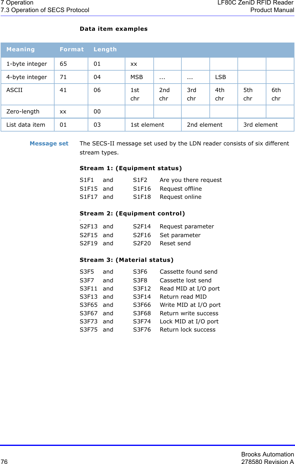
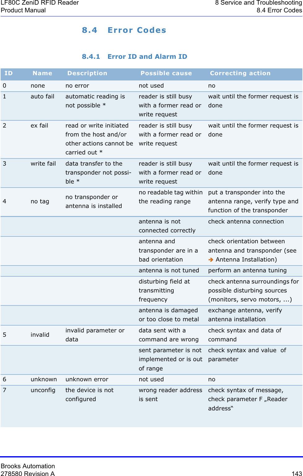
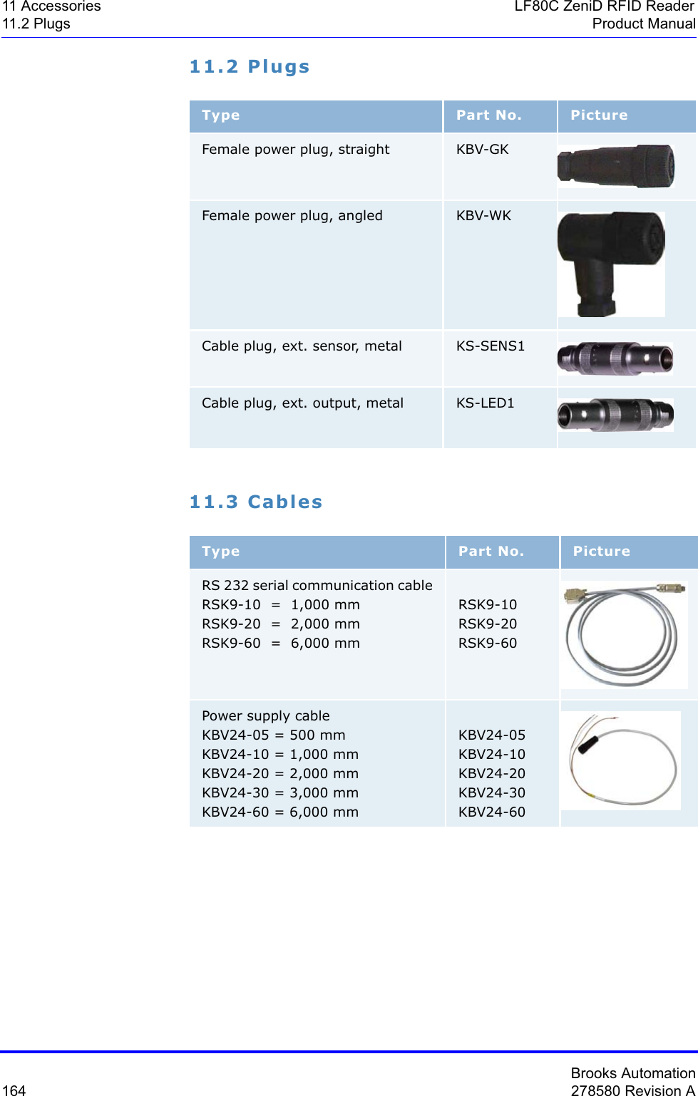
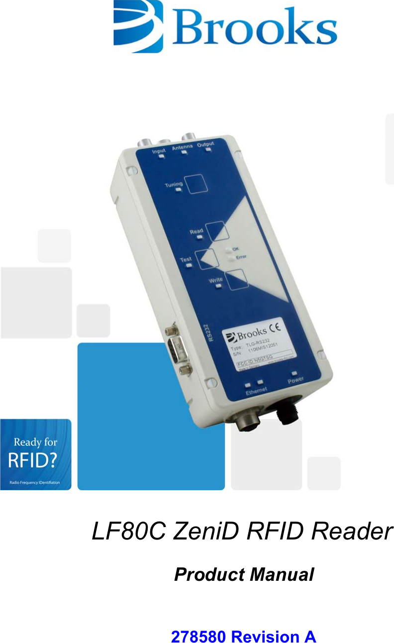
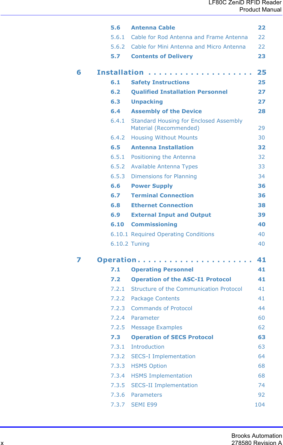
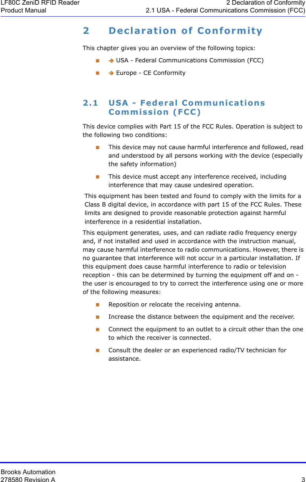
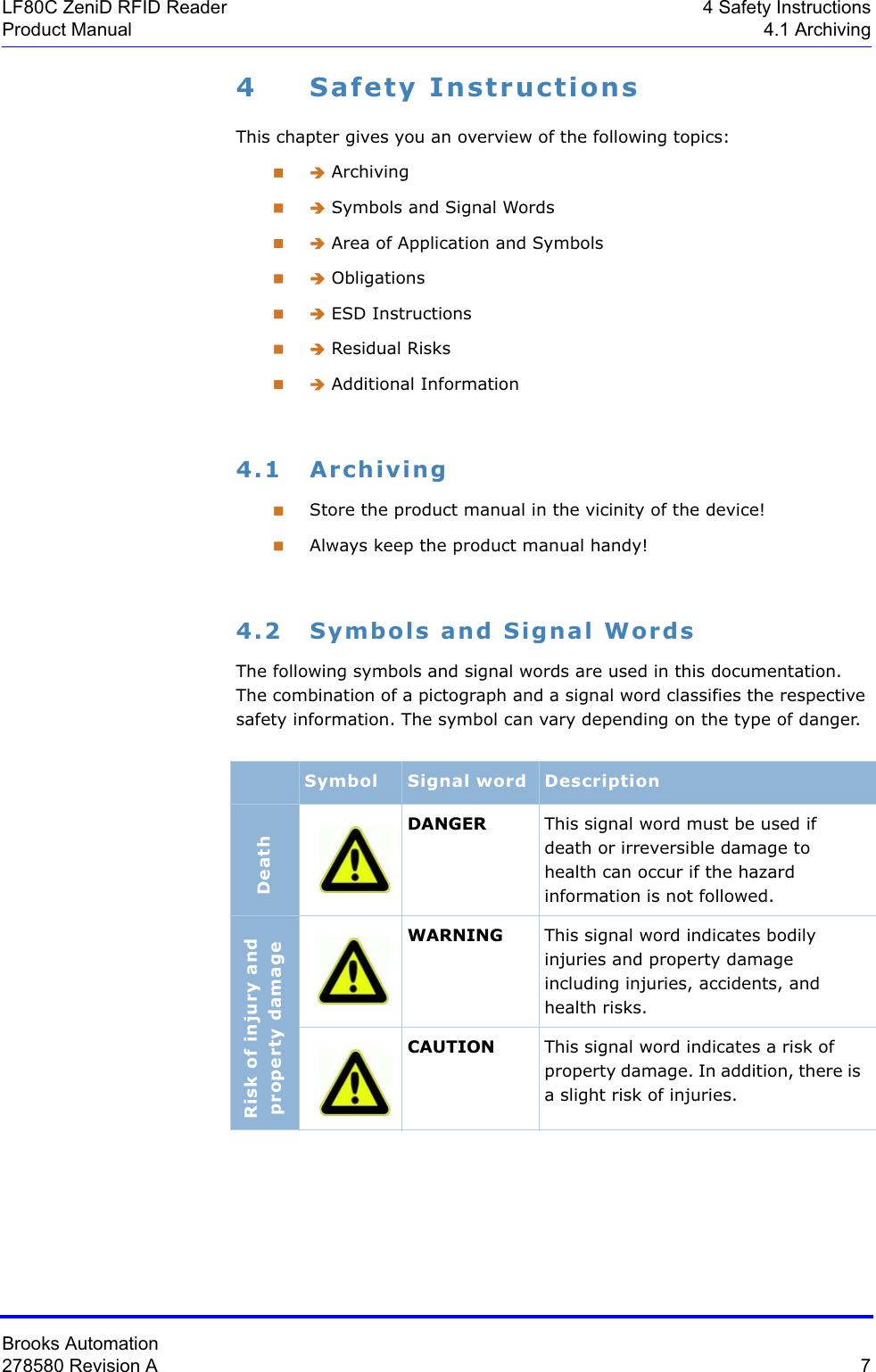
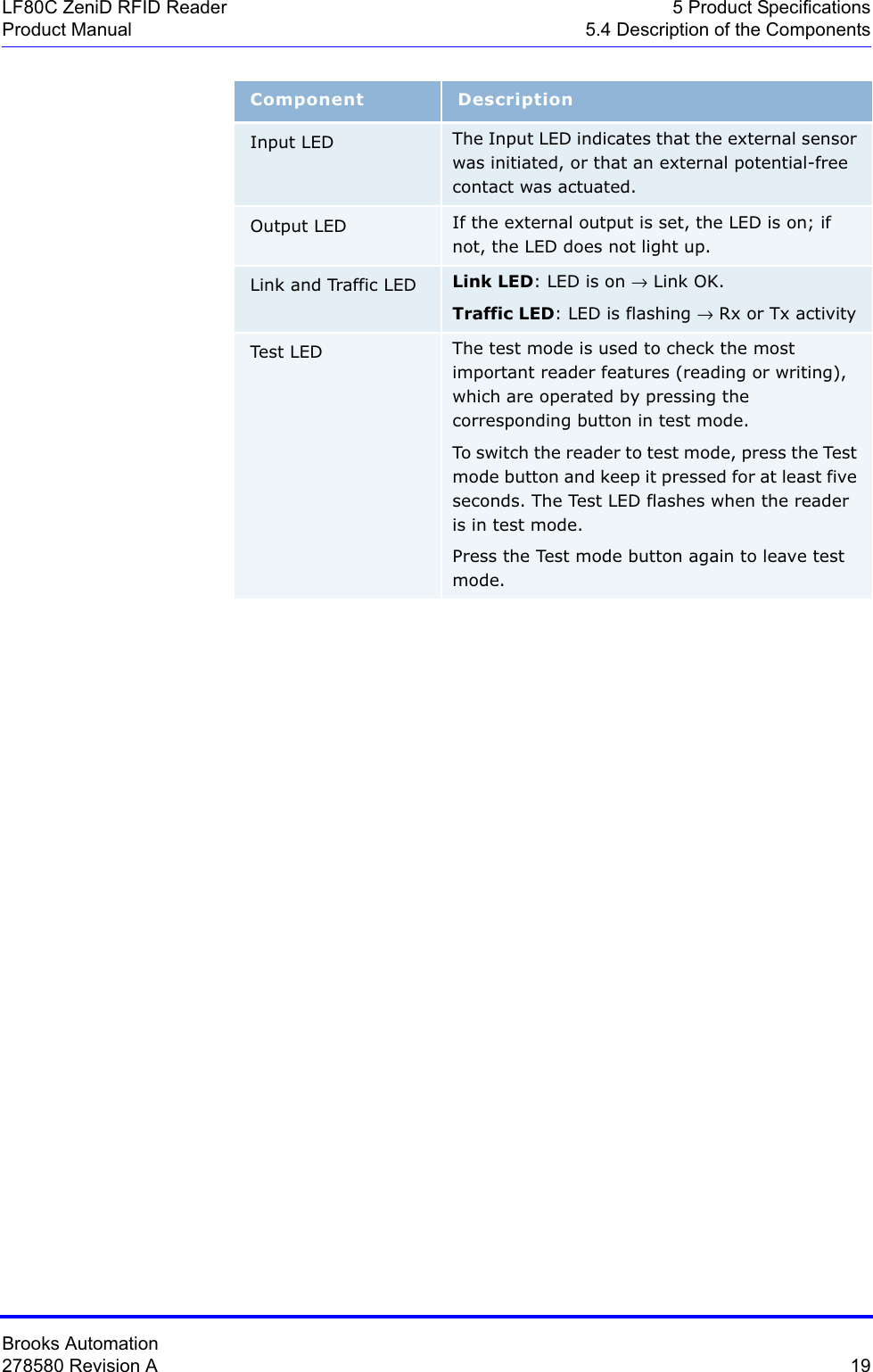
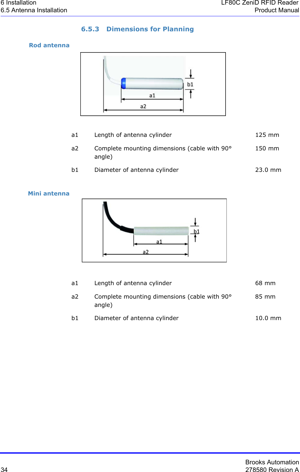
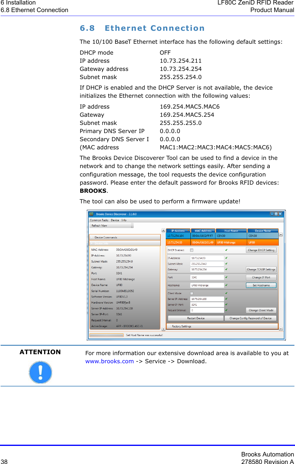
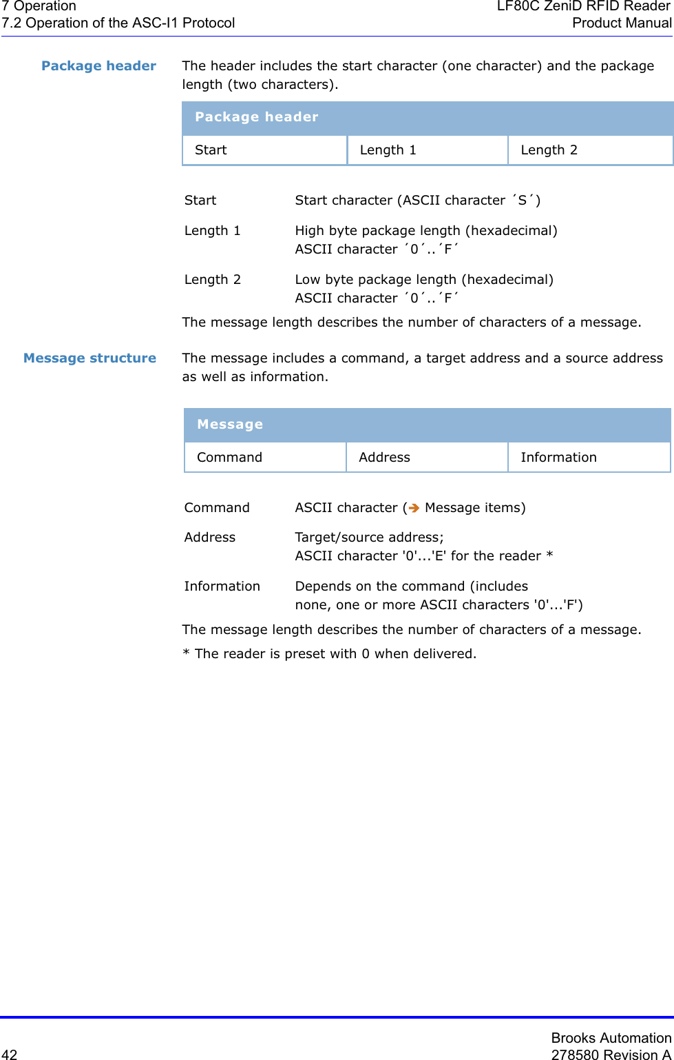
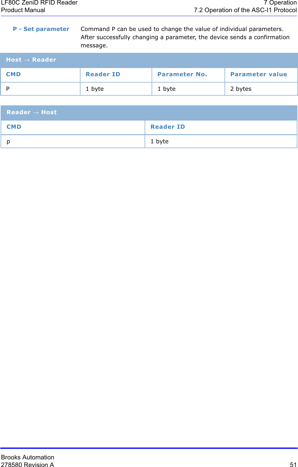
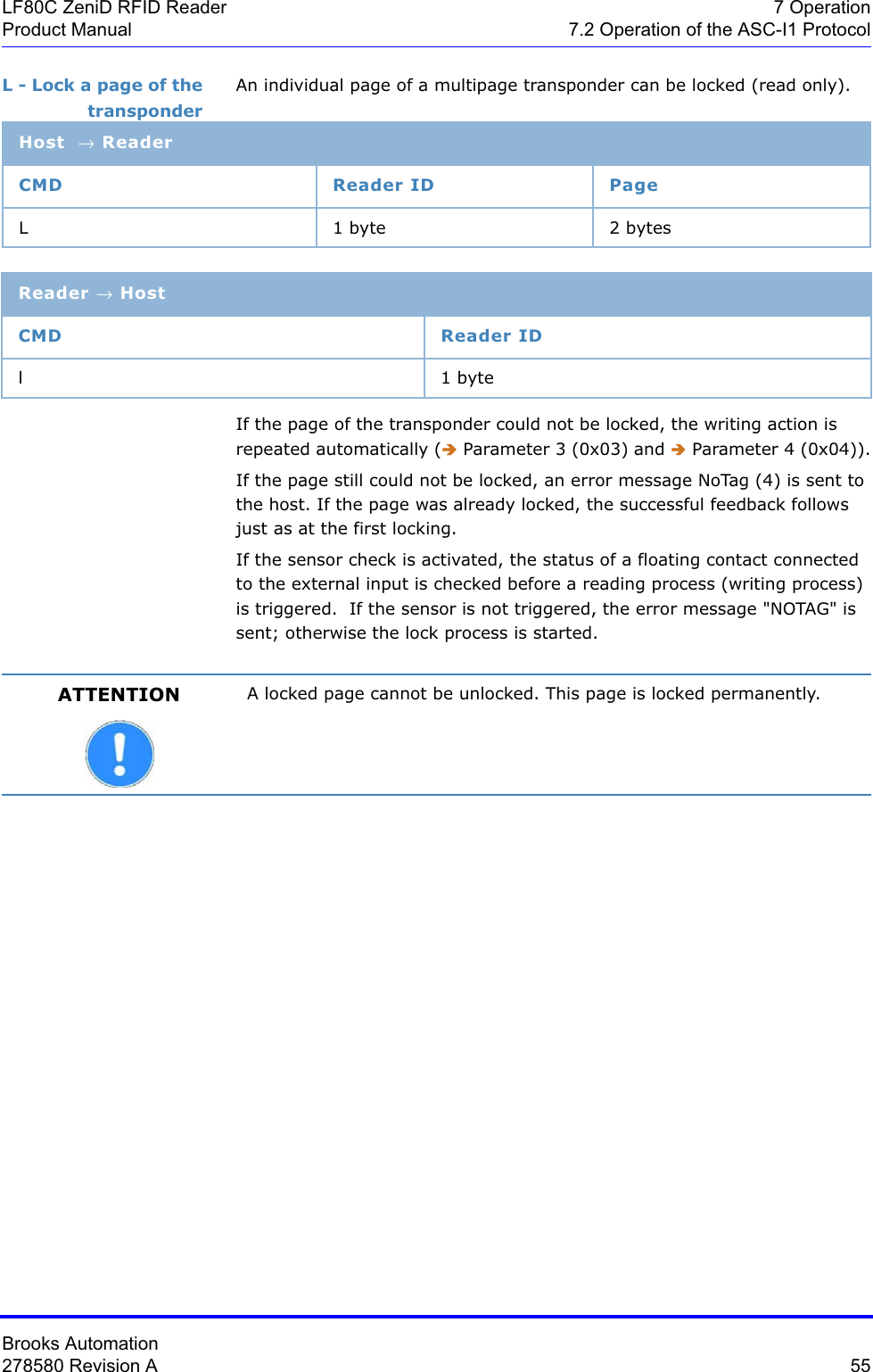
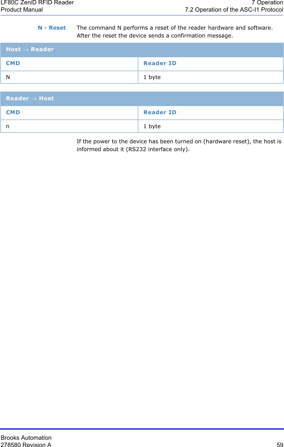
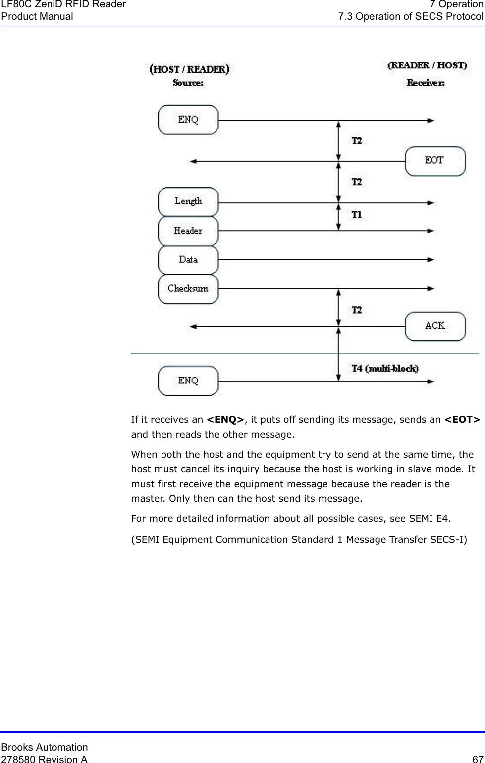
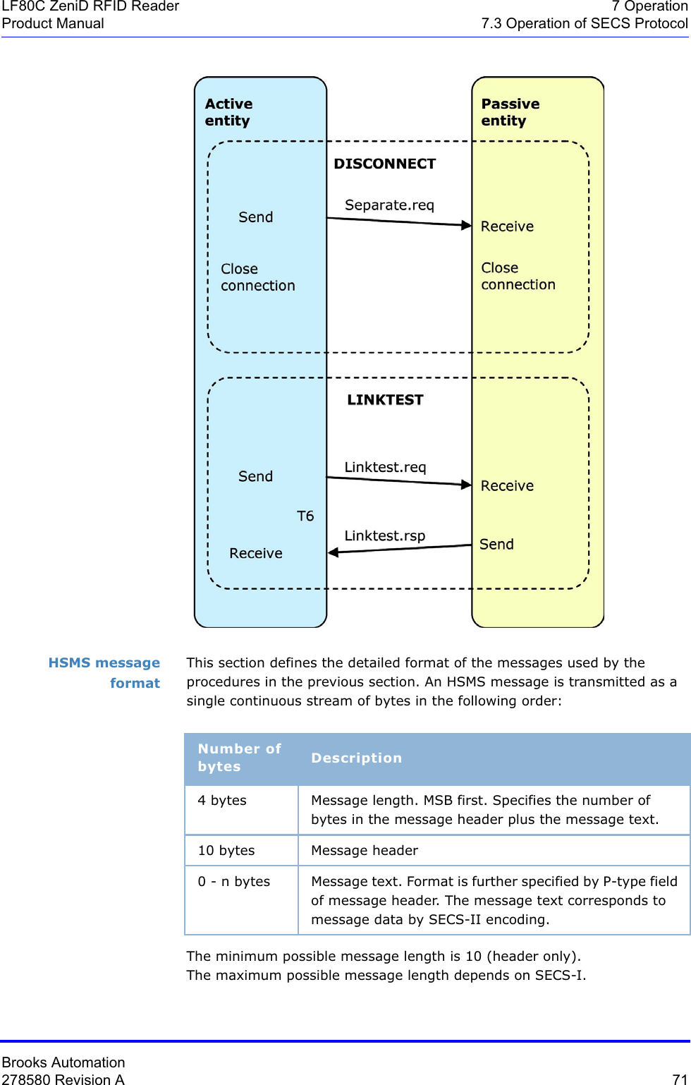
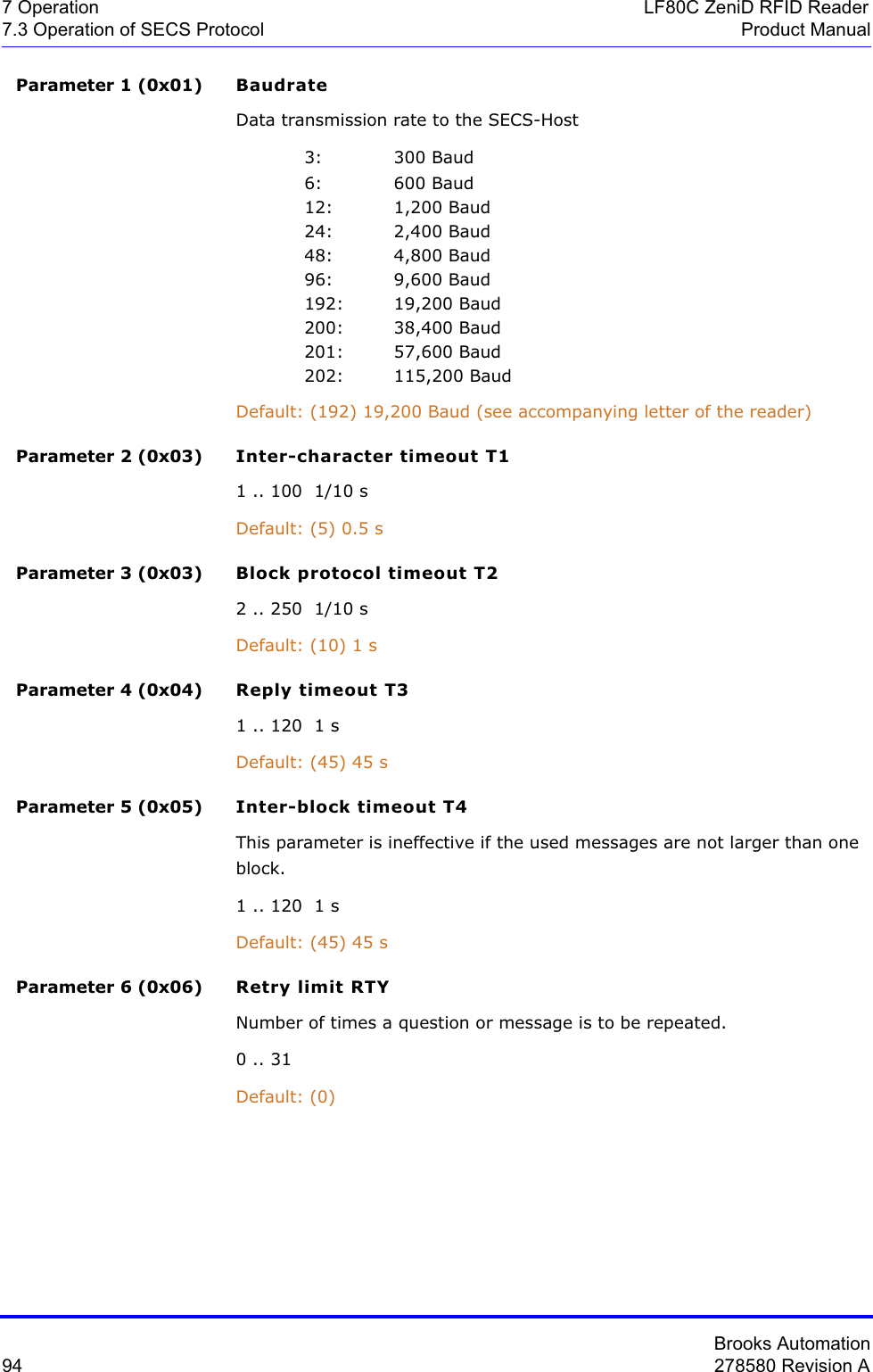
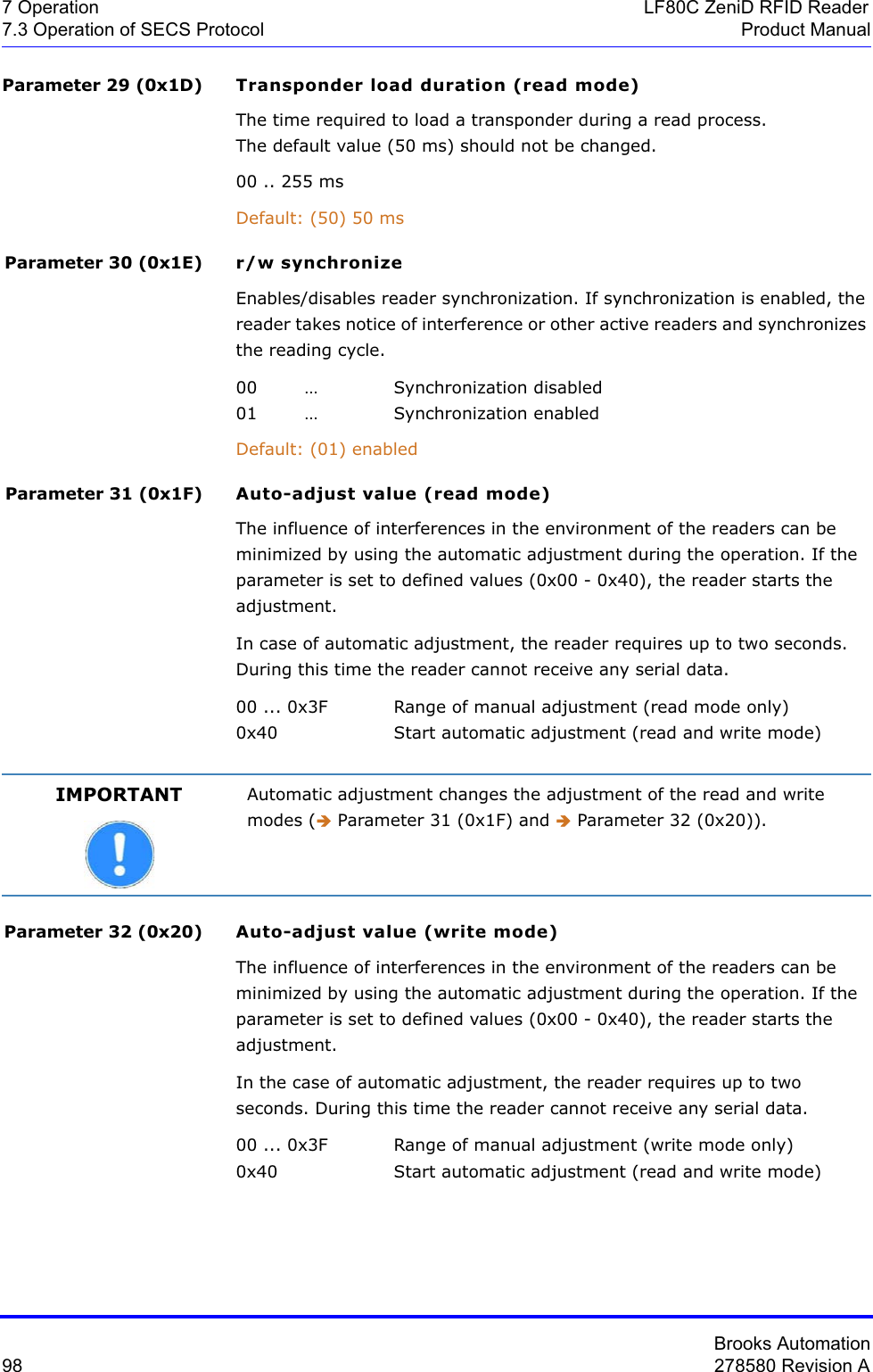
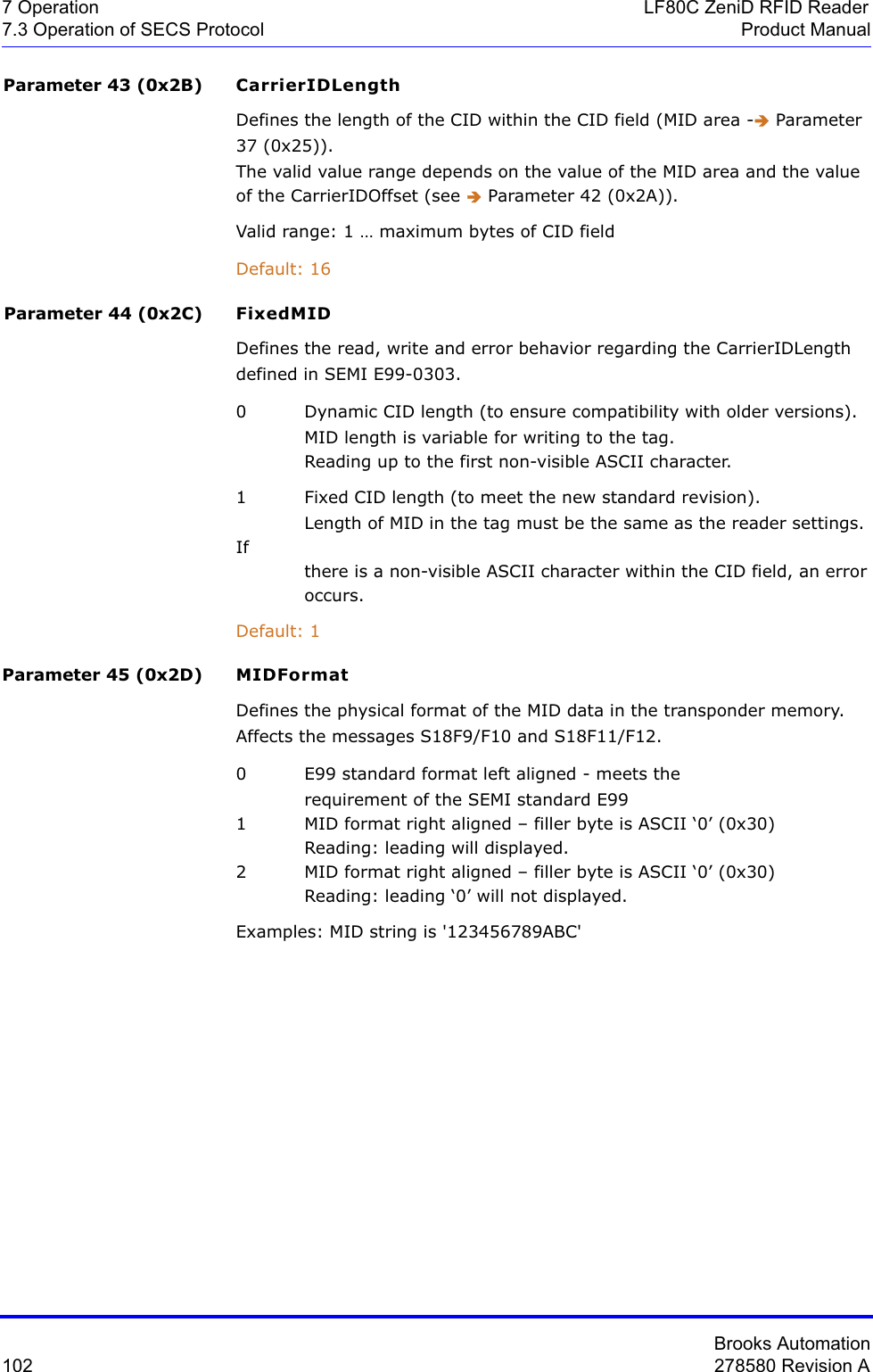
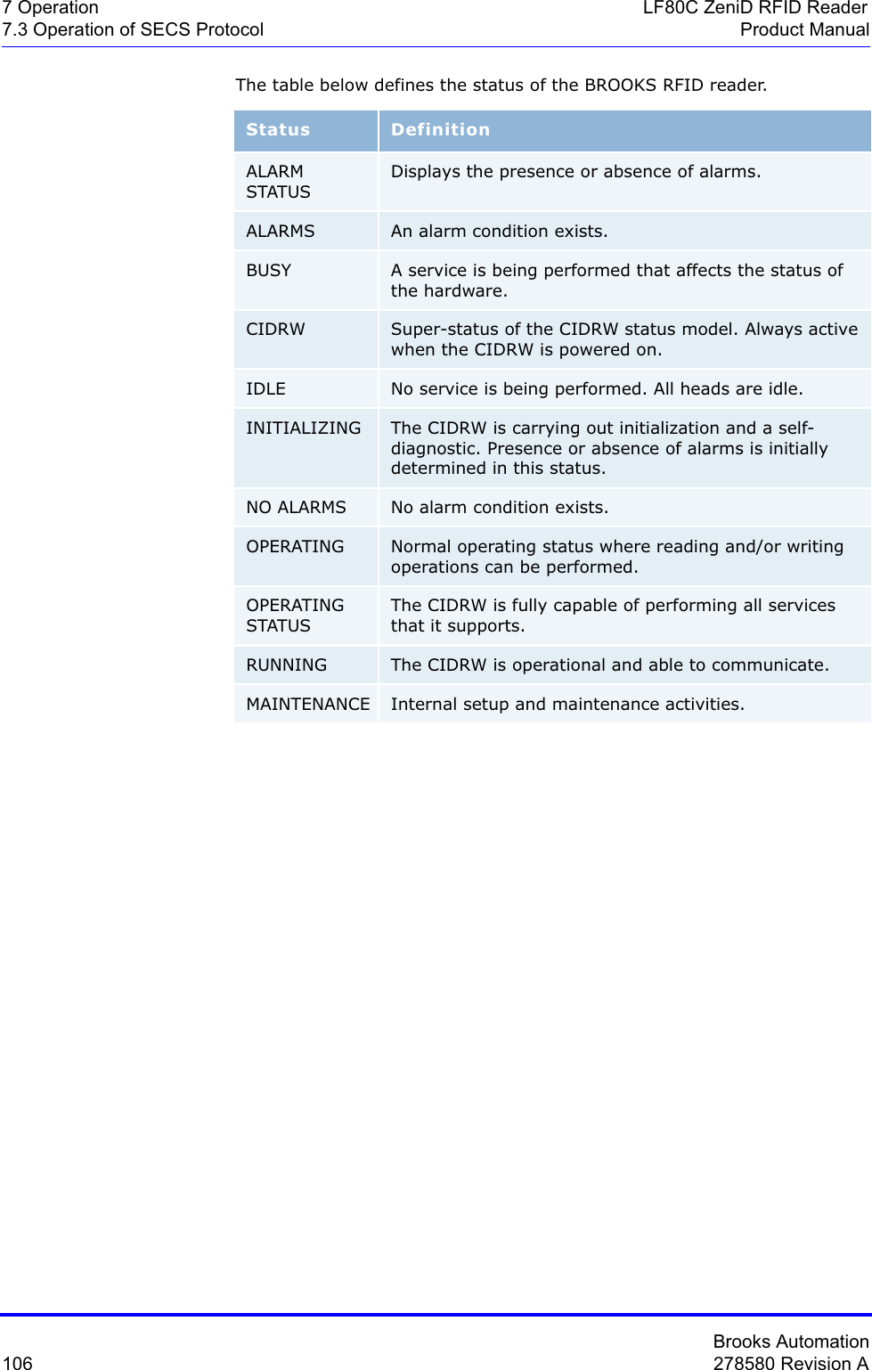
![Brooks Automation78 278580 Revision A7 Operation LF80C ZeniD RFID Reader7.3 Operation of SECS Protocol Product ManualData item dictionary This section defines the data items used in the standard SECS-II messages described in Î Message Details.Syntax:Acknowledge code0 : Sensor 0 was the initiator>0 : Error, not acceptedWhere used S3F6, S3F8Acknowledge code0 : No error>0 : Error, not acceptedWhere used S5F2Name A unique name for this data item. This name is used in the message definitions.Format The permitted item format code which can be used for this standard data item. Item format codes are shown in hex and octal, as described in the chapter Î Data items. The notification "3()" indicates any of the signed integer formats (30, 31, 32, 34).Description A description of the data item, with the meanings of specific values.Where used The standard messages in which the data item appears.ACKC3 Format: B[1]ACKC5 Format: B[1]](https://usermanual.wiki/Brooks-Automation/LF80BC1/User-Guide-3980249-Page-90.png)
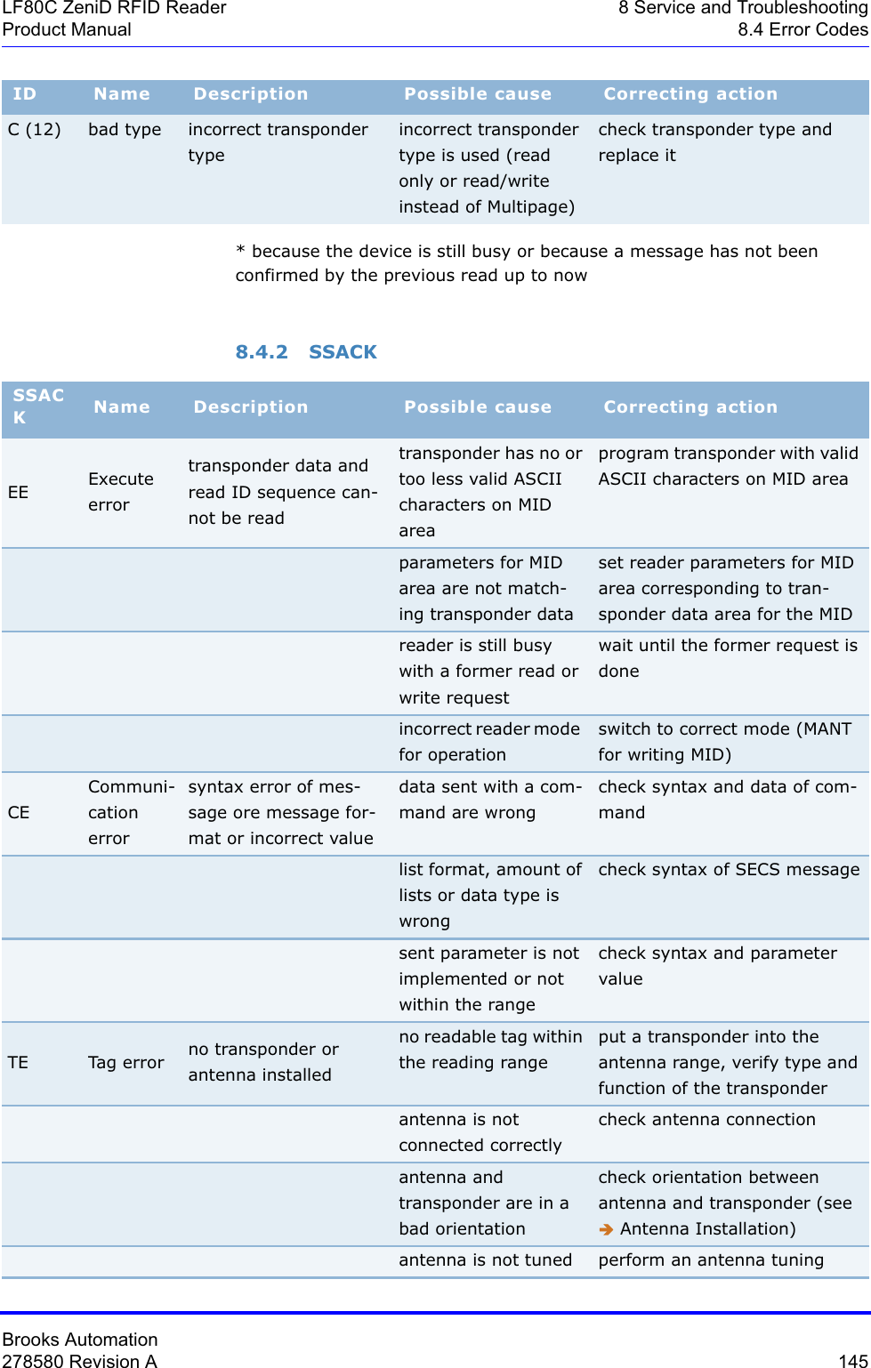
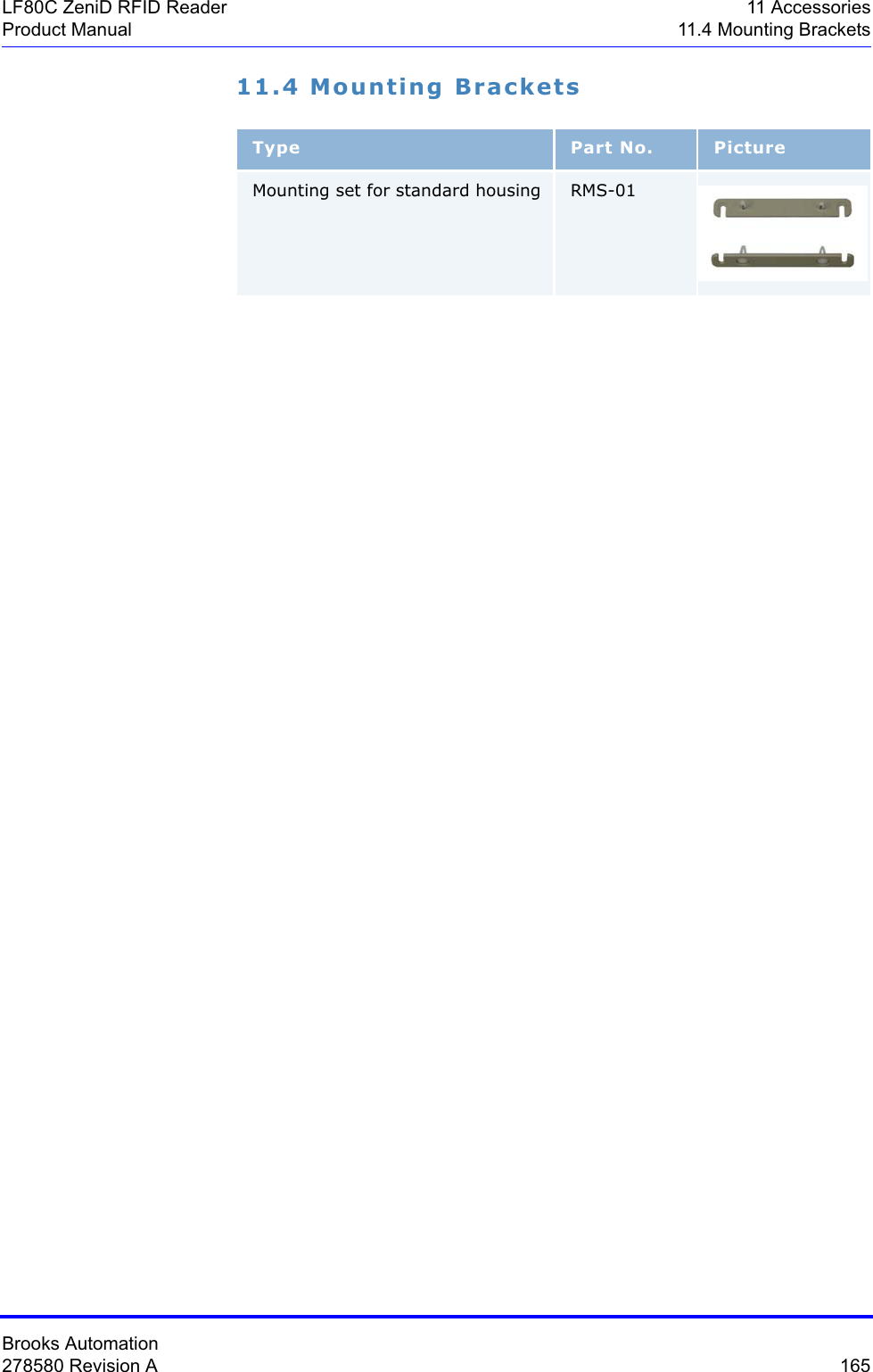
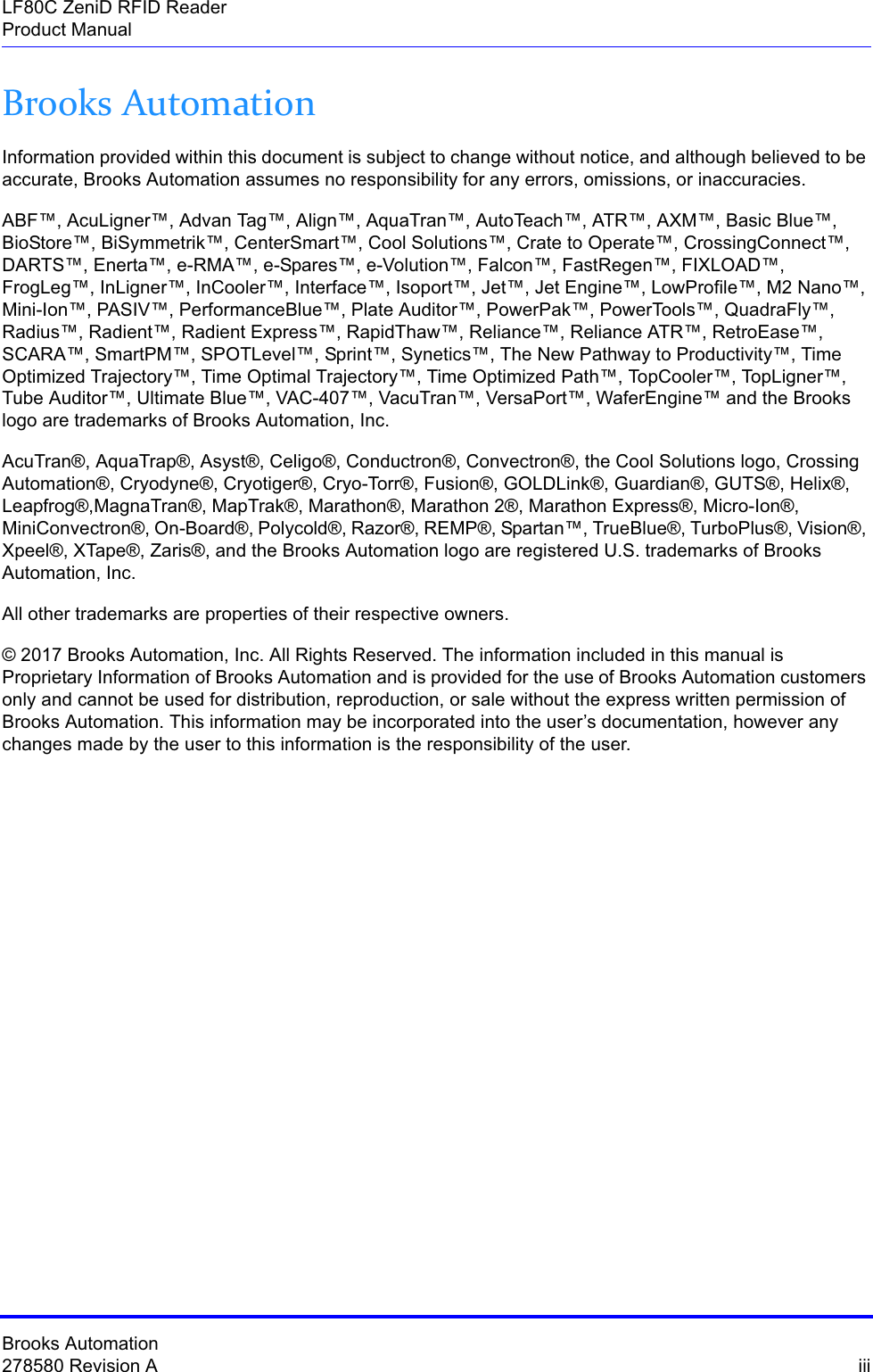
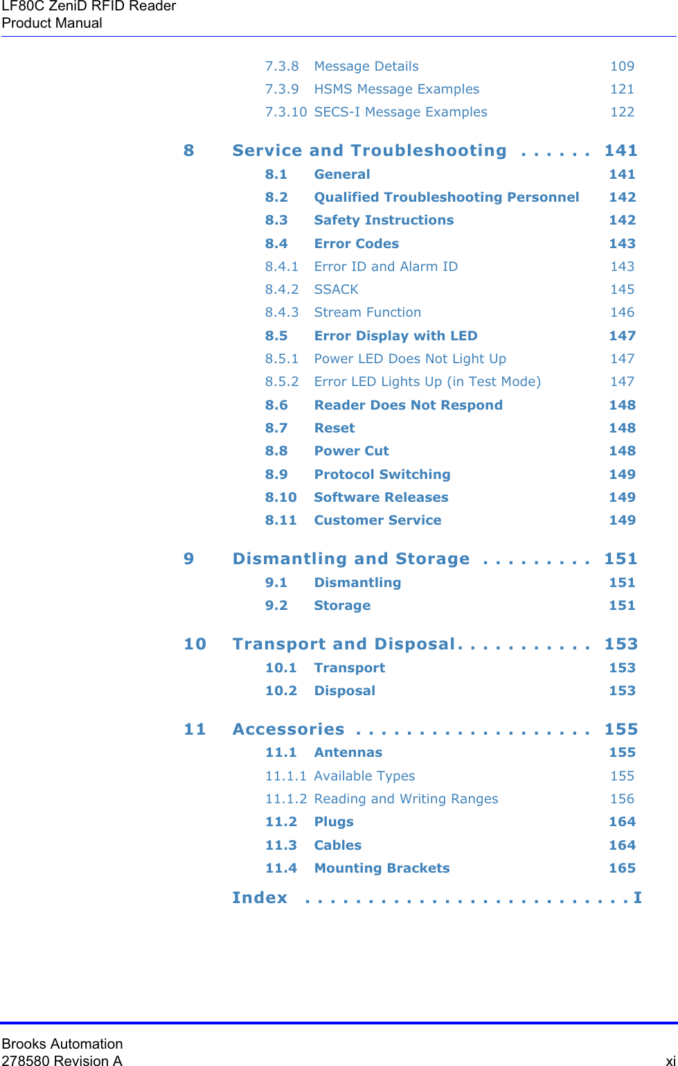
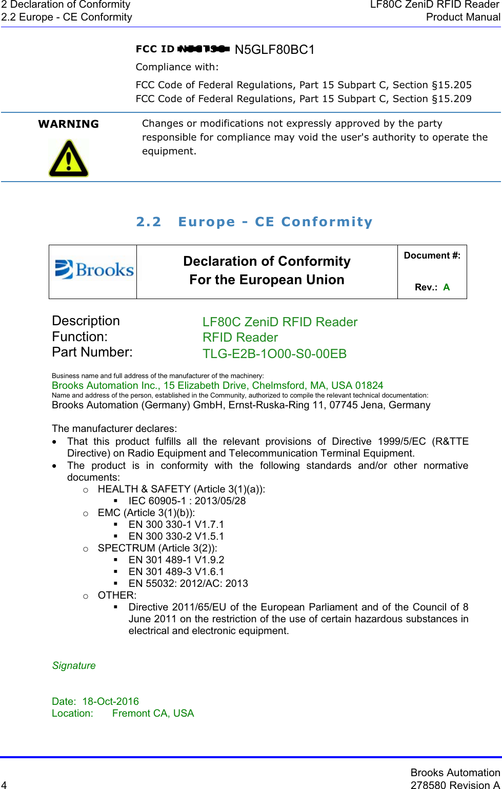
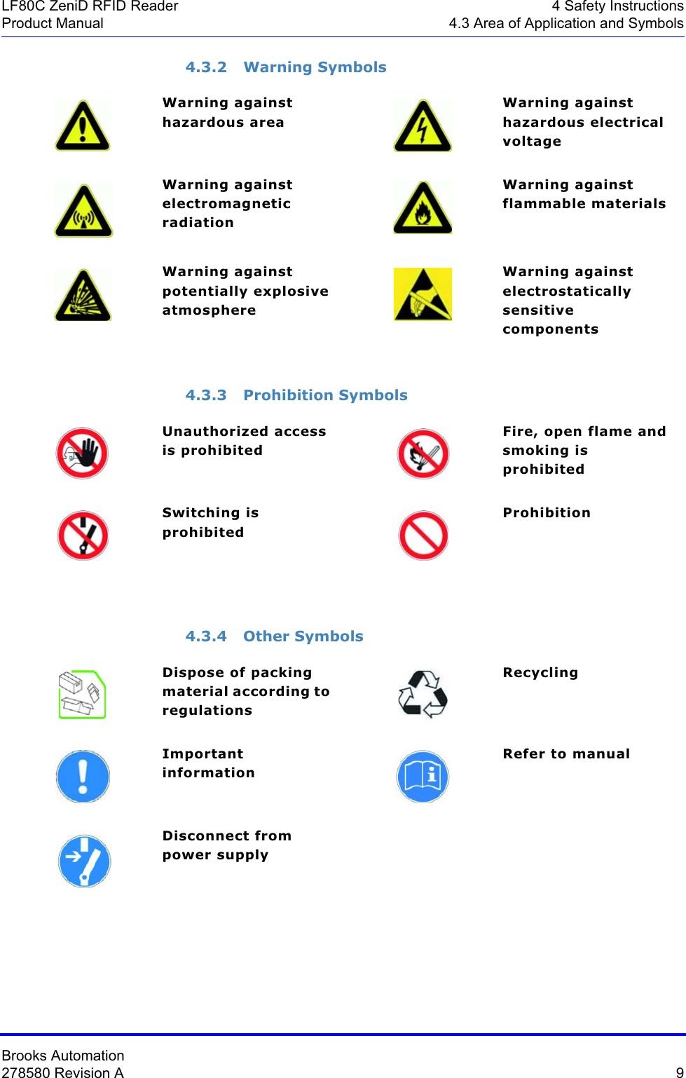
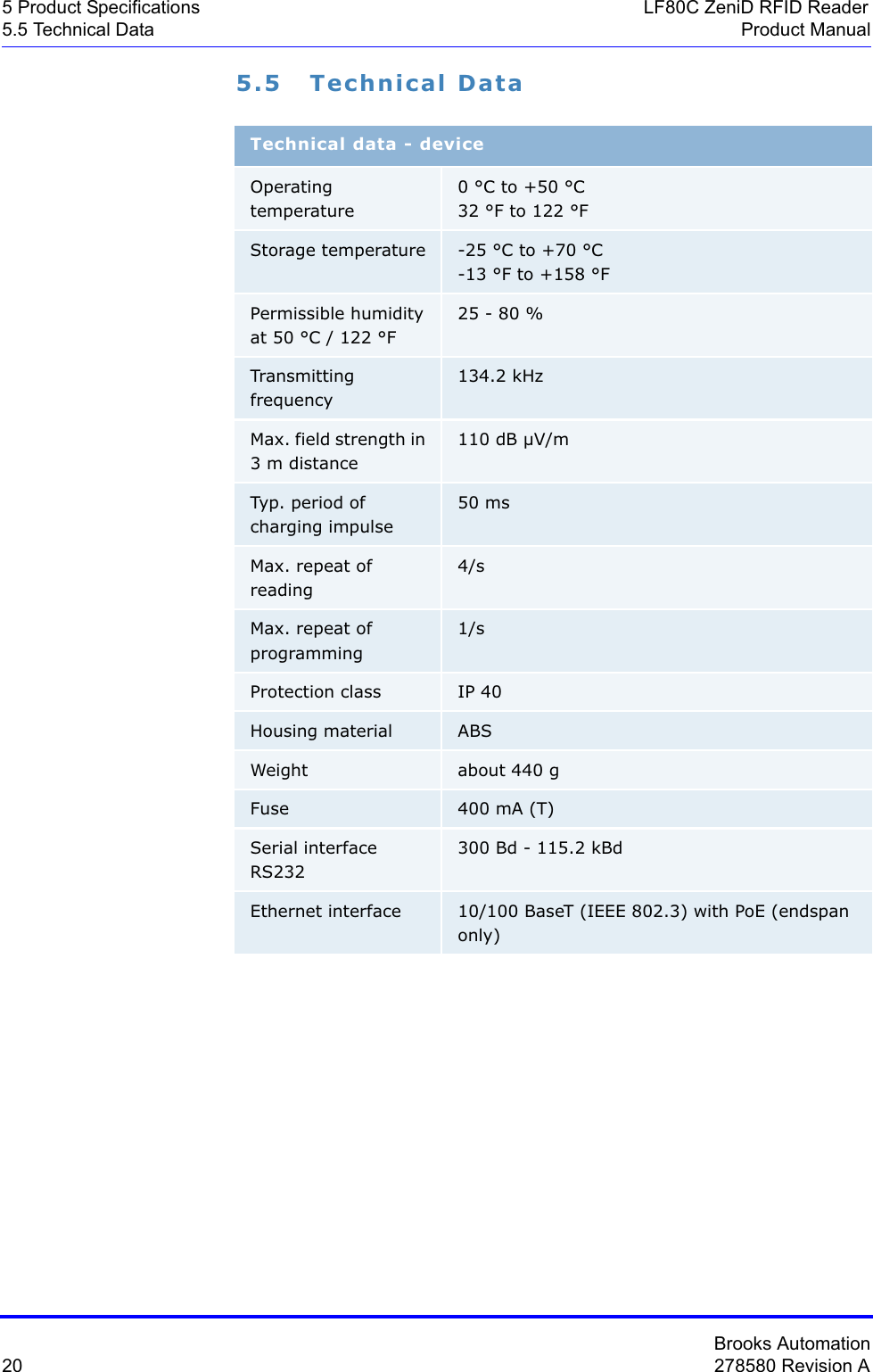
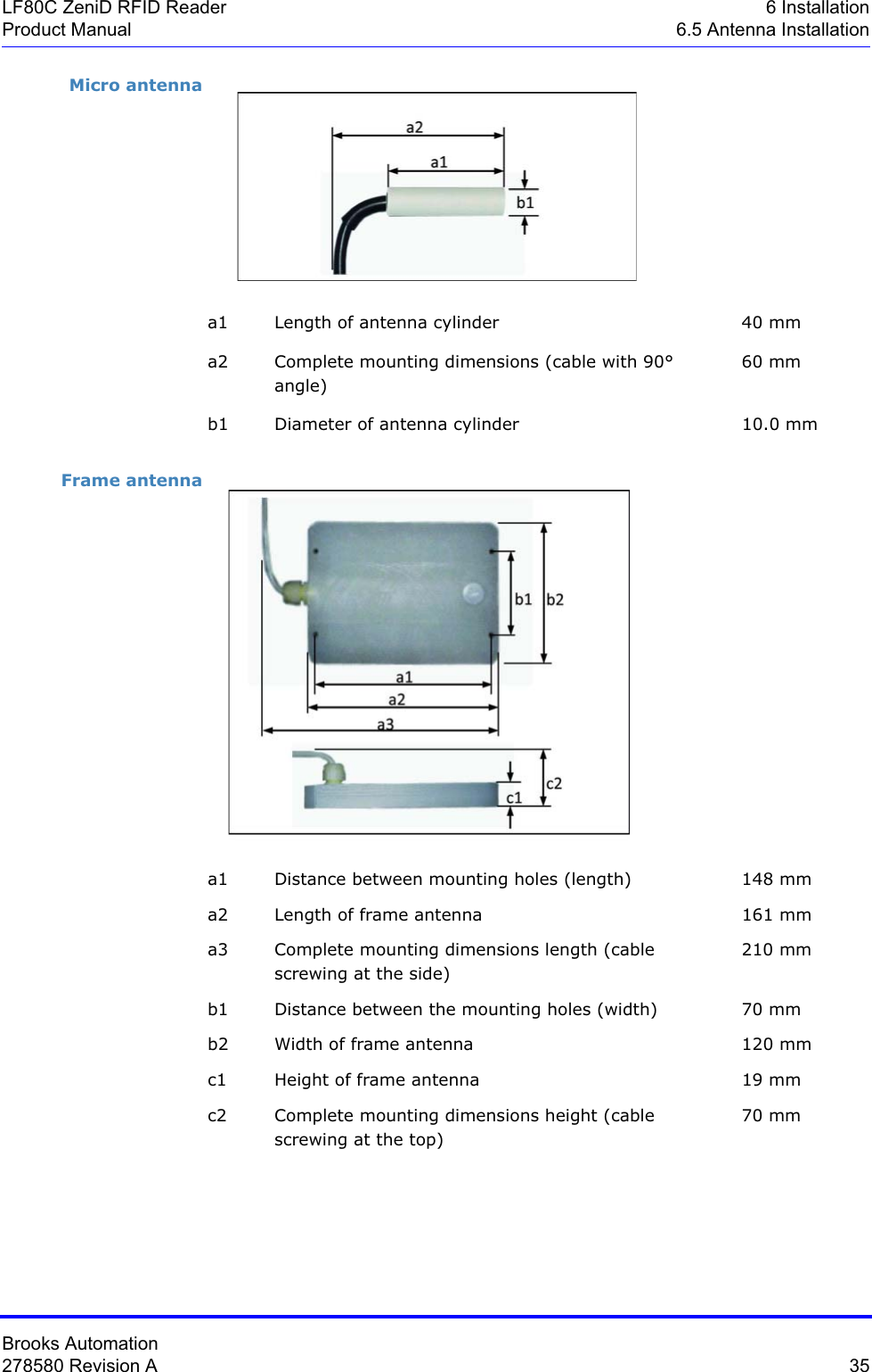
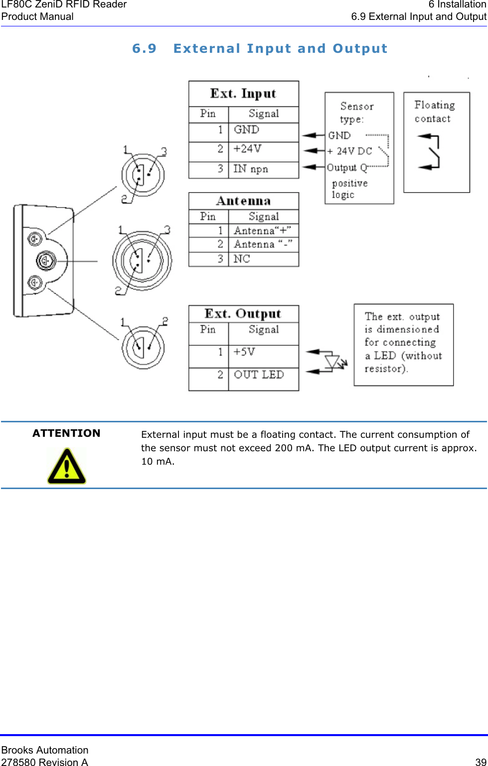
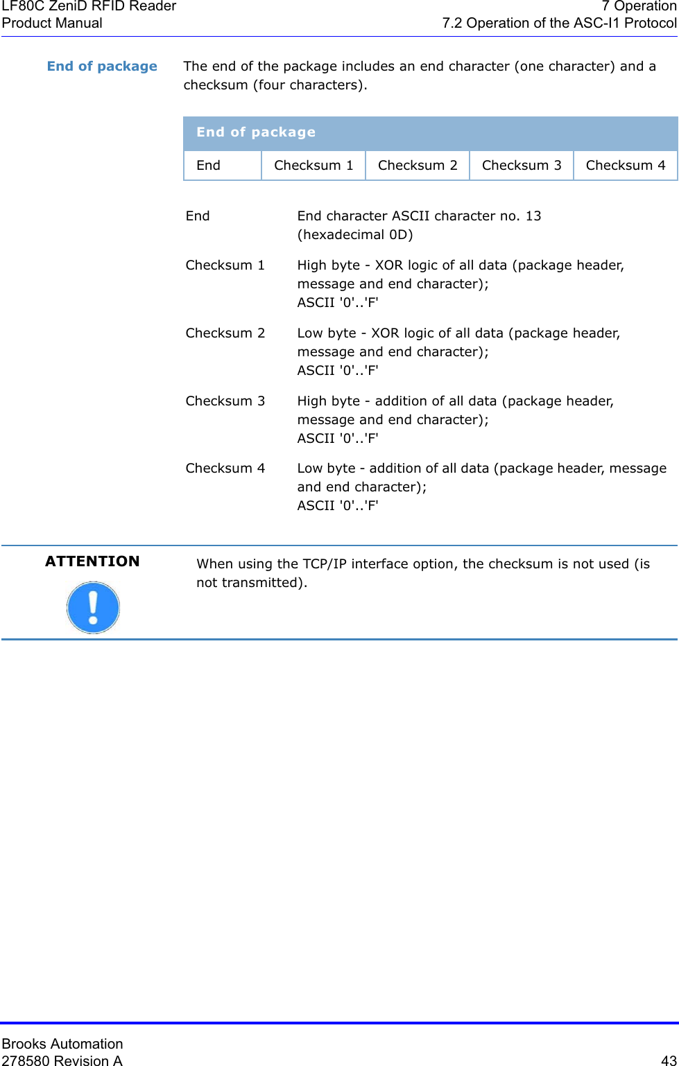
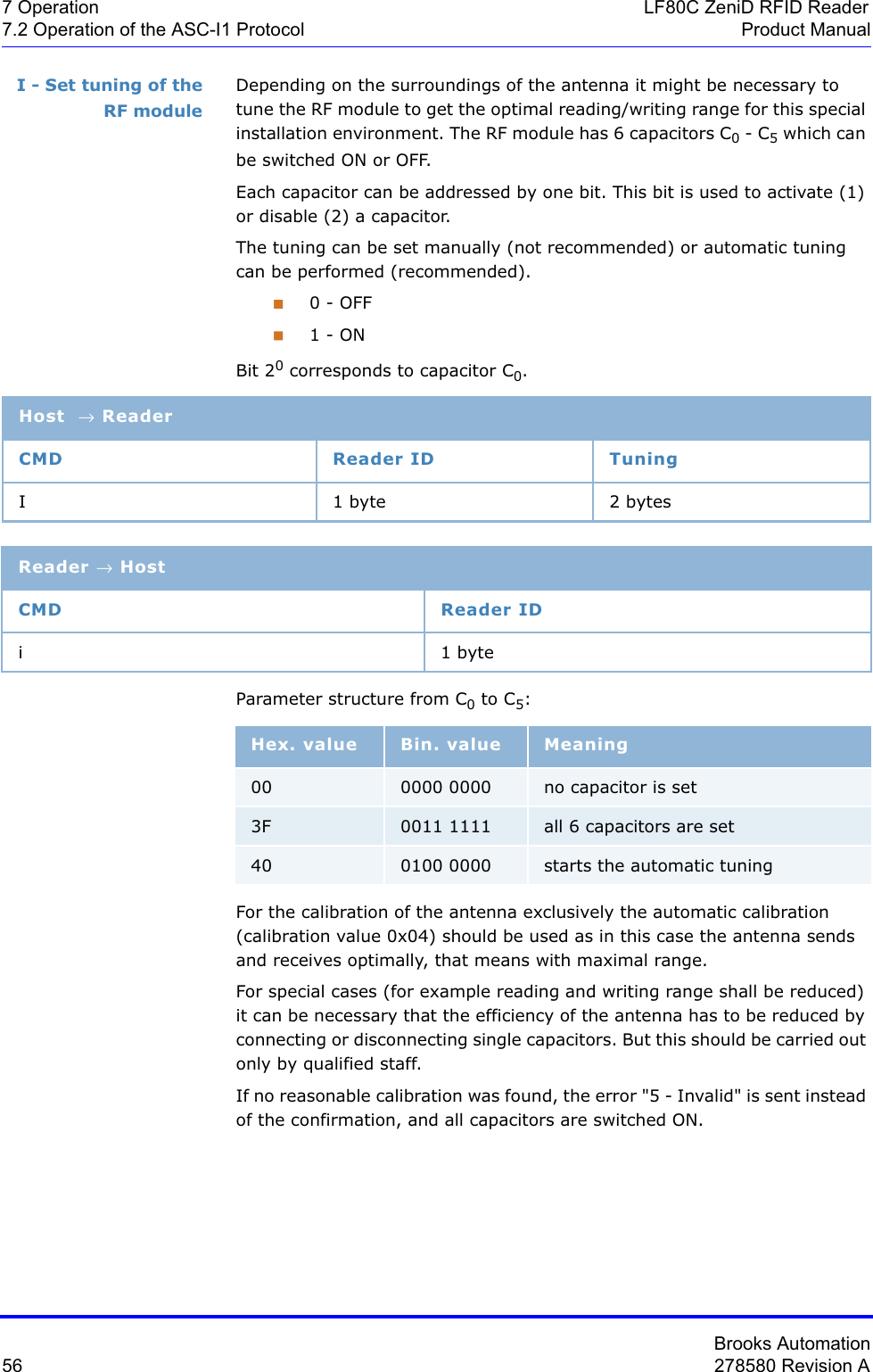
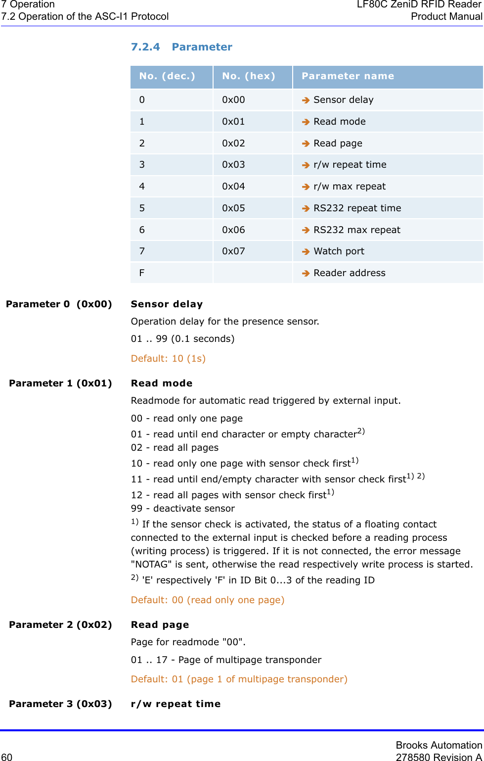
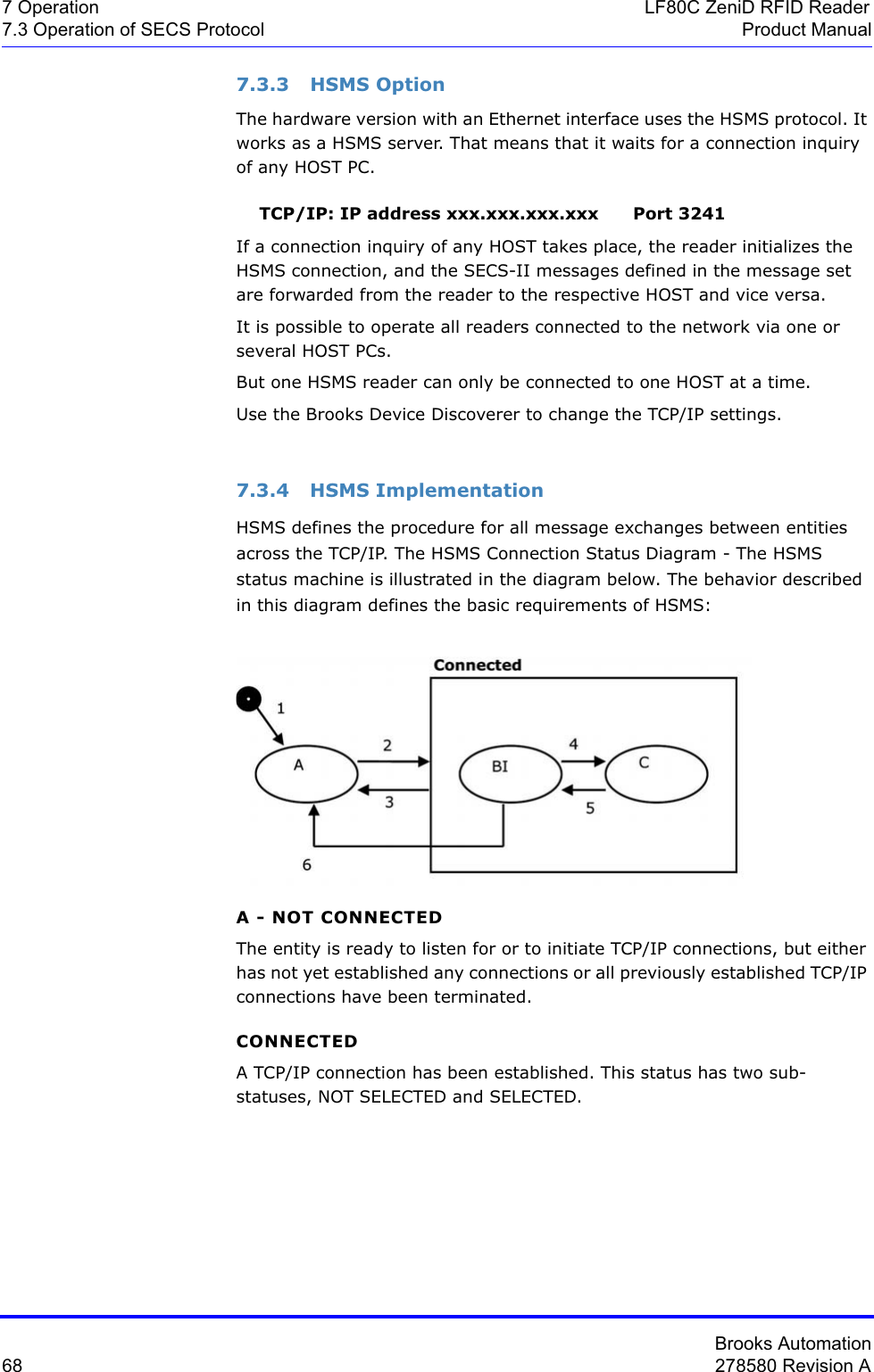
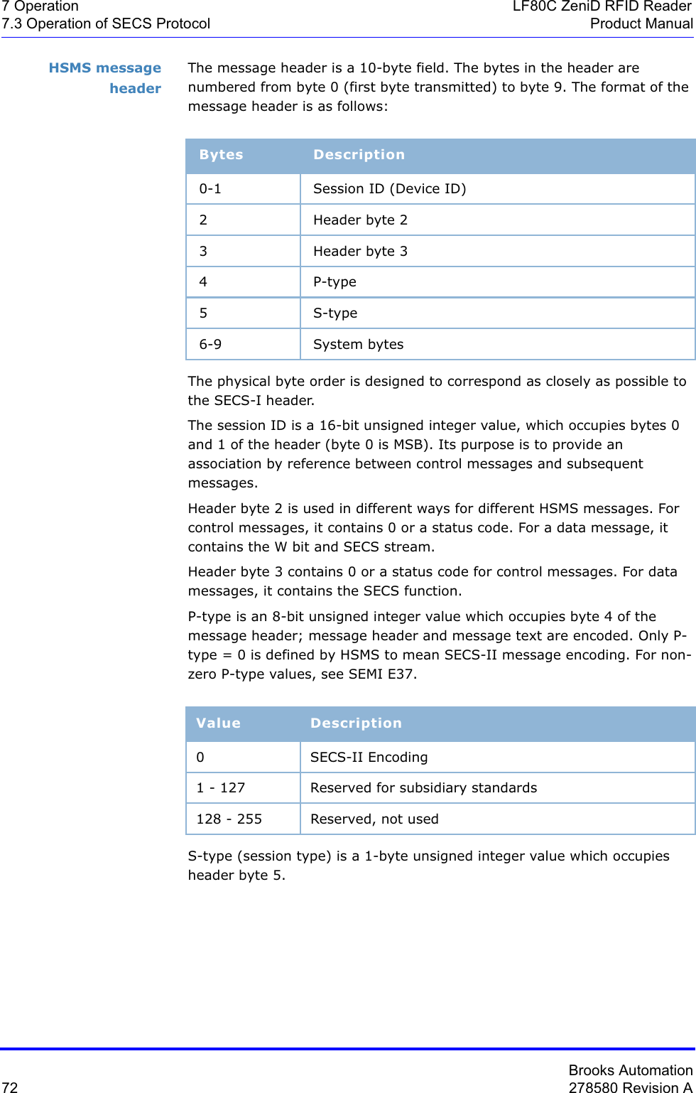
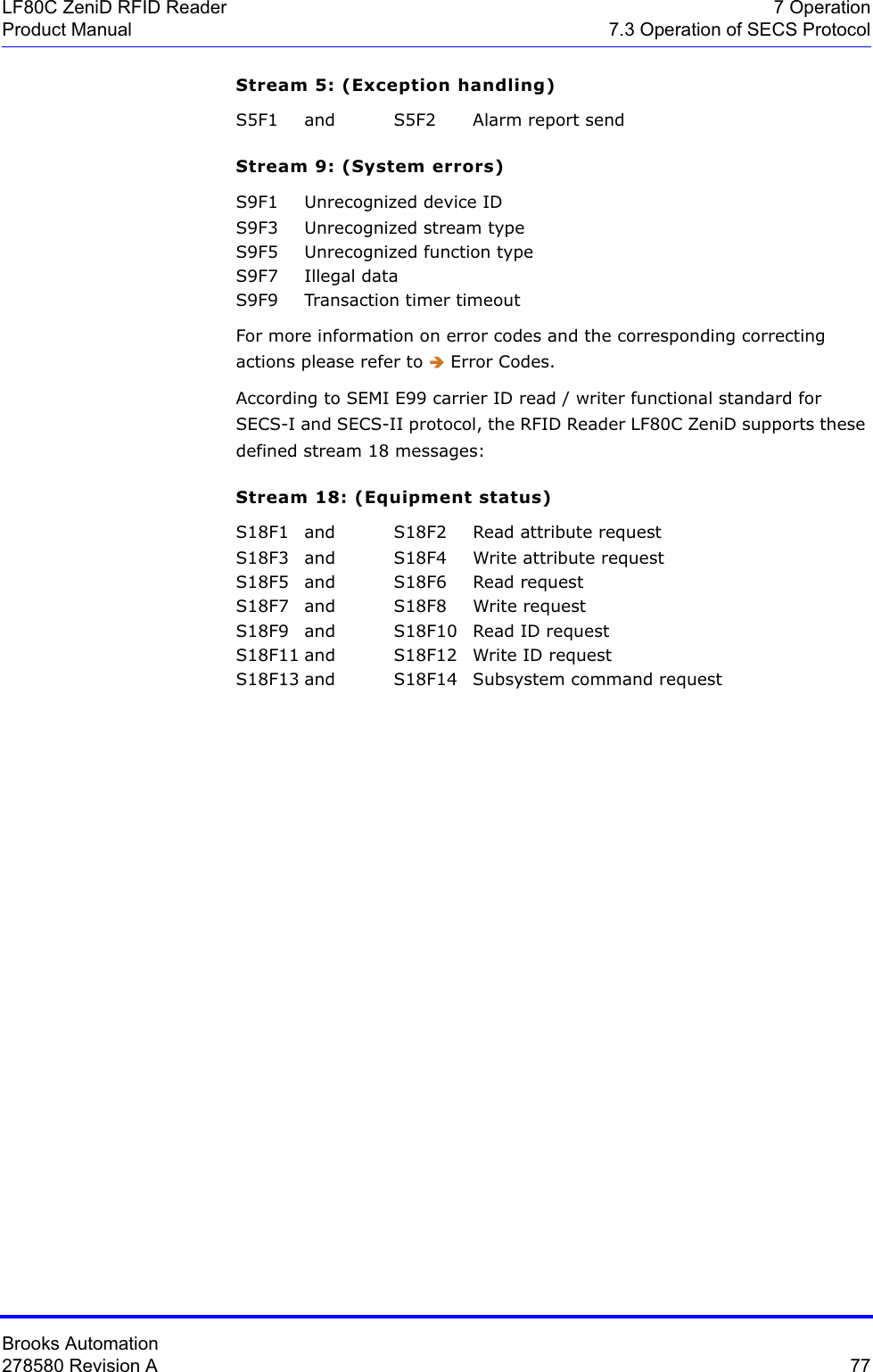
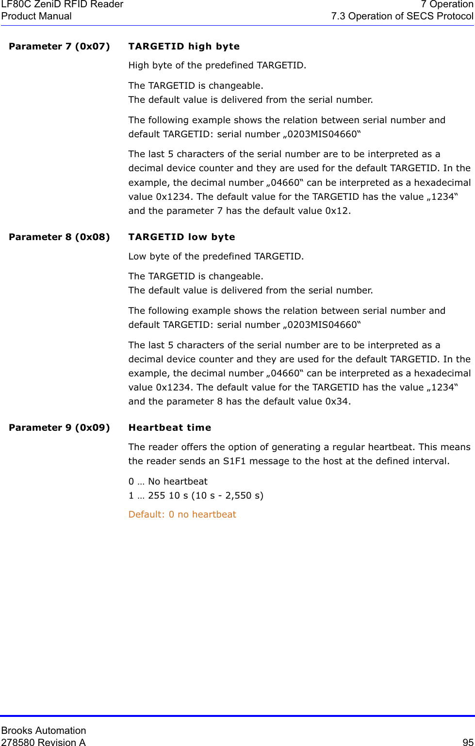
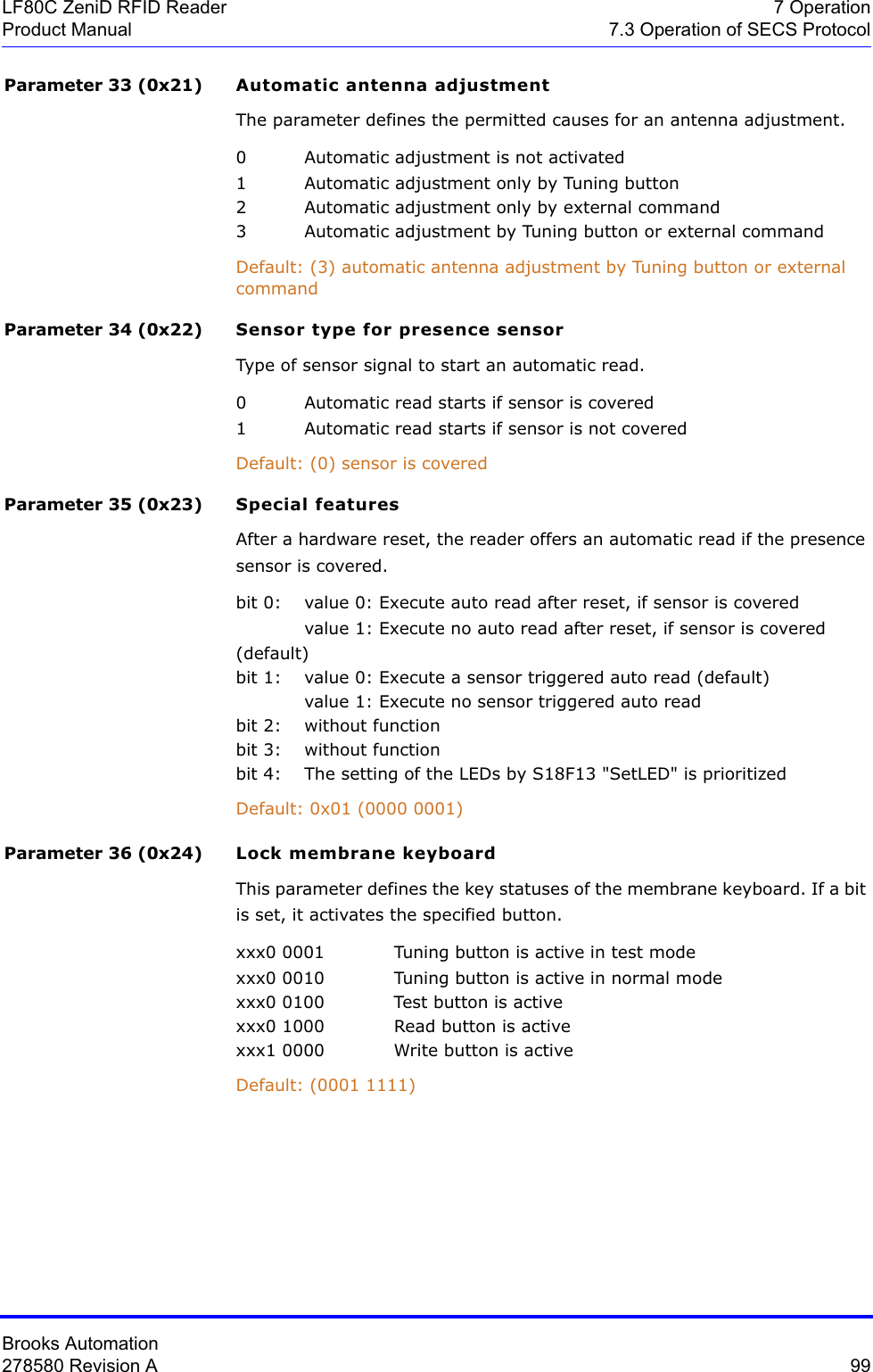
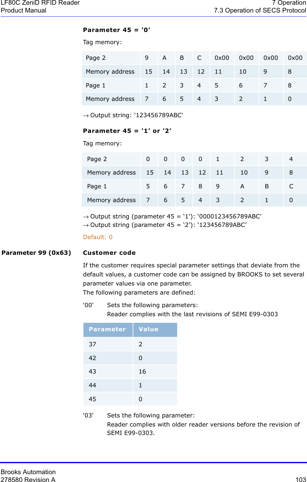
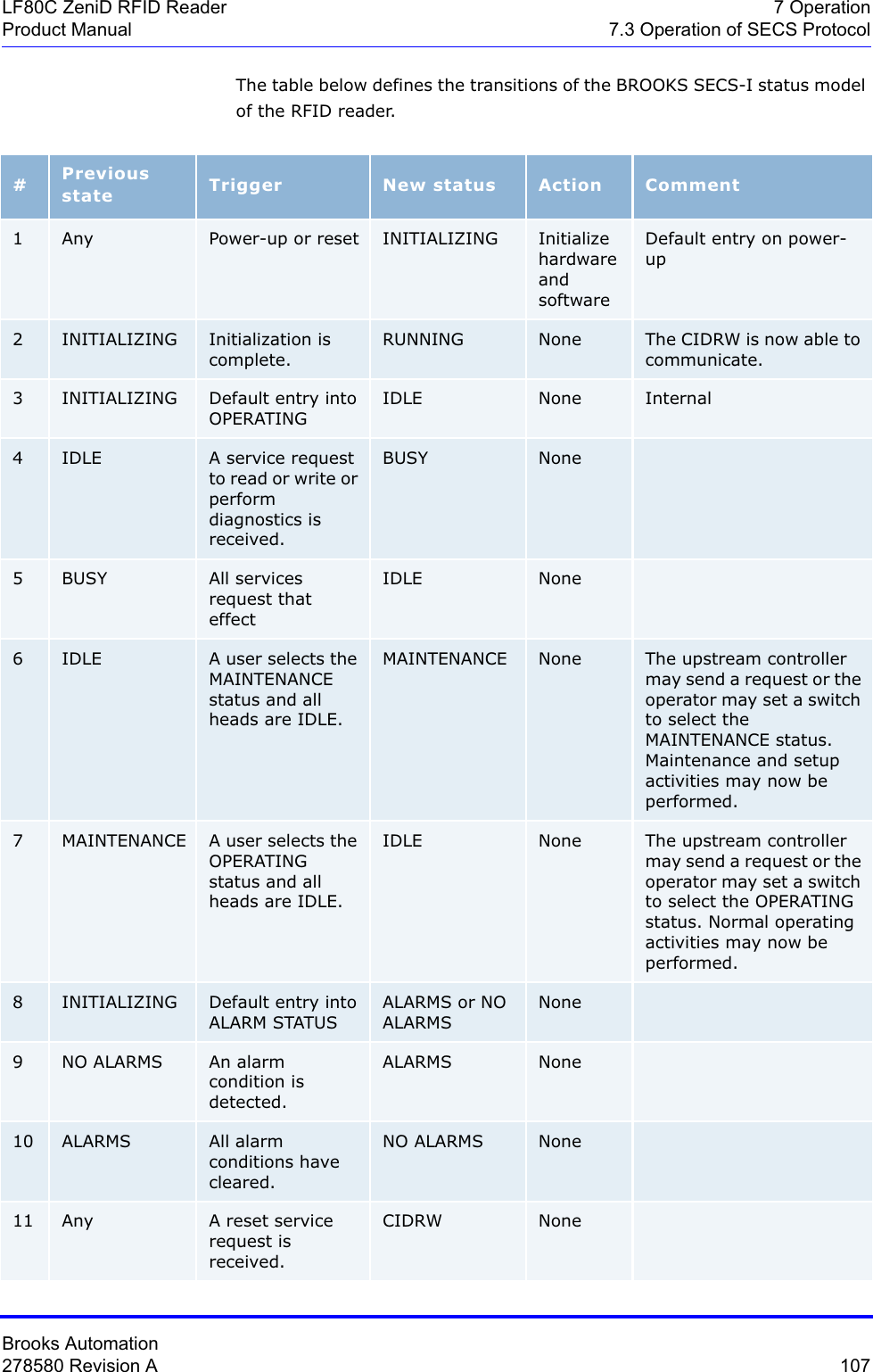
![Brooks Automation278580 Revision A 79LF80C ZeniD RFID Reader 7 OperationProduct Manual 7.3 Operation of SECS ProtocolDescription The value of the alarm status refers to the last reading process. If a read or write error occurs, the alarm status is set. A successful read or write resets the alarm status. When leaving maintenance mode, the alarm status is also deleted.0 ... No alarm1 ... AlarmWhere used S18F13Alarm code byteOnly the occurrence of an error is reported. Errors are not generally reset.bit 8 = 1 Alarm is setWhere used S5F1Alarm identifier0 No error1 Auto read failed, the reader is engaged 2 External read failed, the reader is engaged 3 External write failed, the reader is engaged 4 No tag could be recognized when the sensor was covered or the carrier had been removed prematurely (sensor uncovered)5 Invalid command or parameter detected6 Unknown error7 Reserved8 Parity error or checksum error detected9 Unexpected confirmation was sent10 Locked page could not be written11 Reserved12 Incorrect type of transponder13 External read or write failed because the sensor is not coveredALARM STATUS Format: A[1]ALCD Format: B[1]ALID Format: B[1]](https://usermanual.wiki/Brooks-Automation/LF80BC1/User-Guide-3980249-Page-91.png)
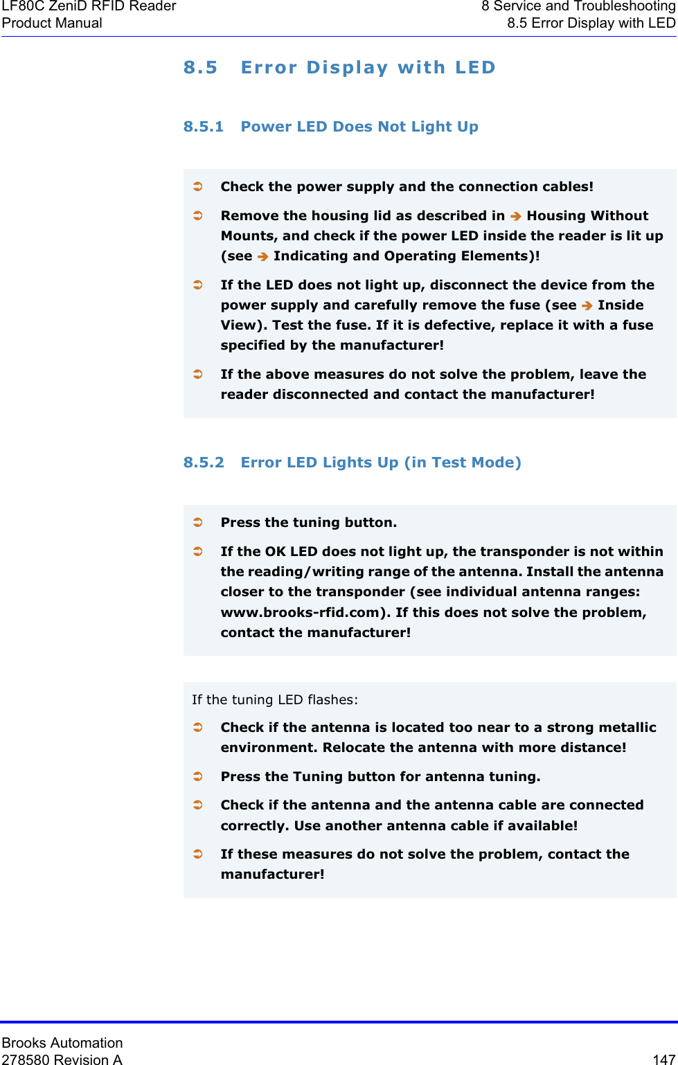
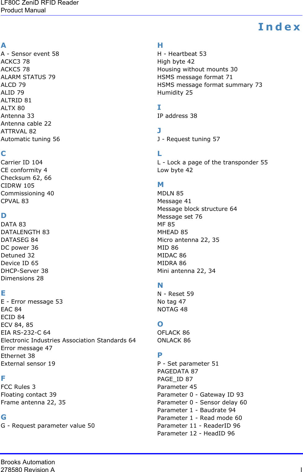
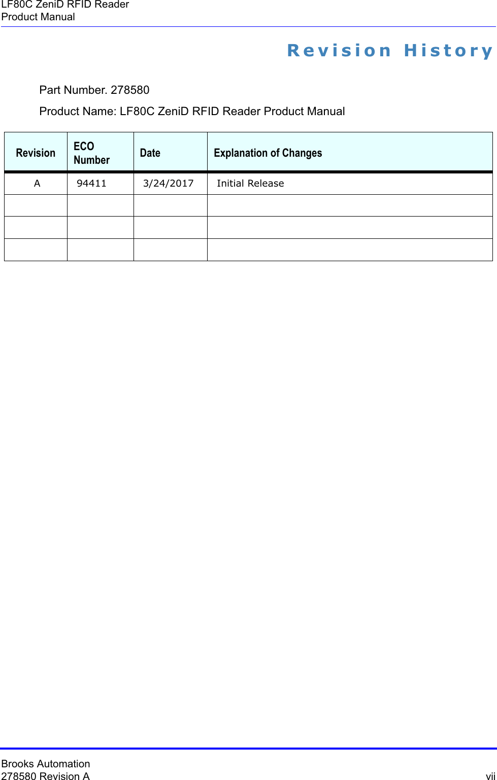
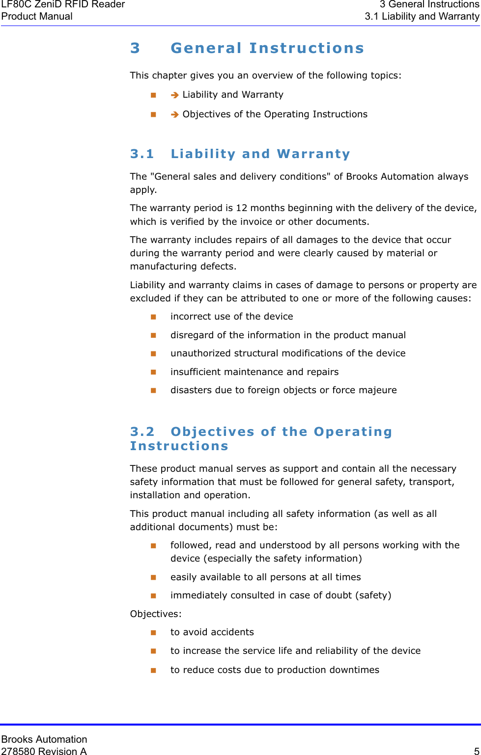
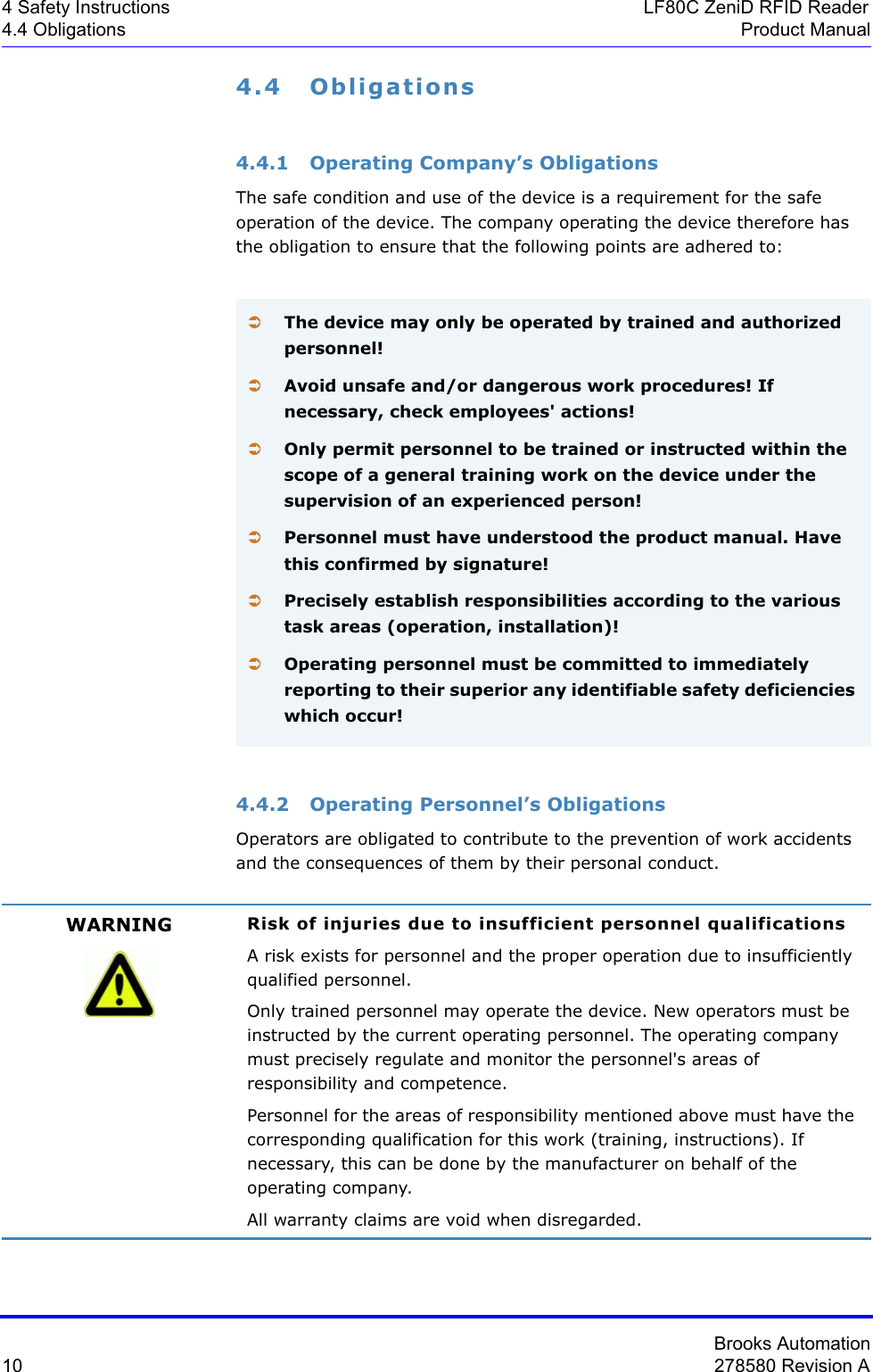
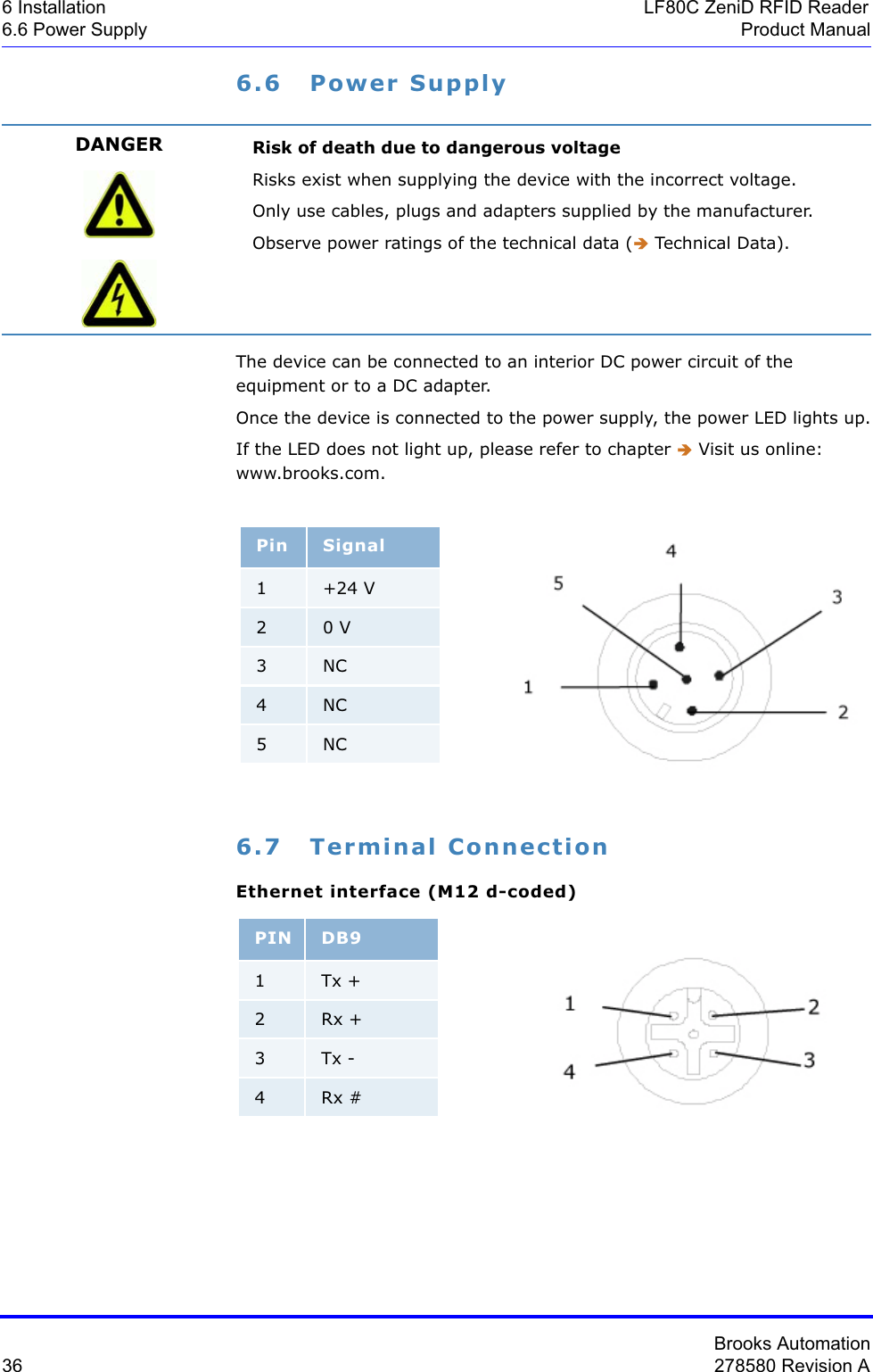
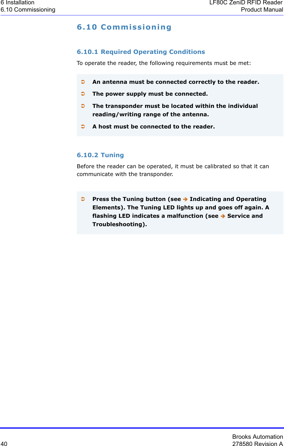
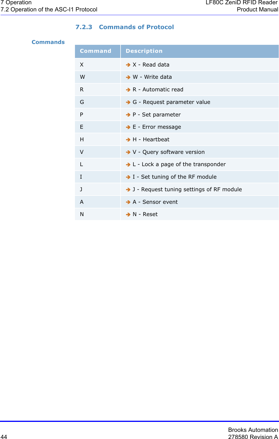
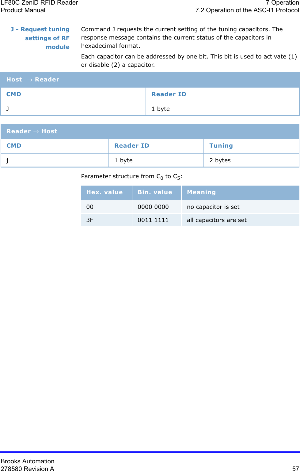
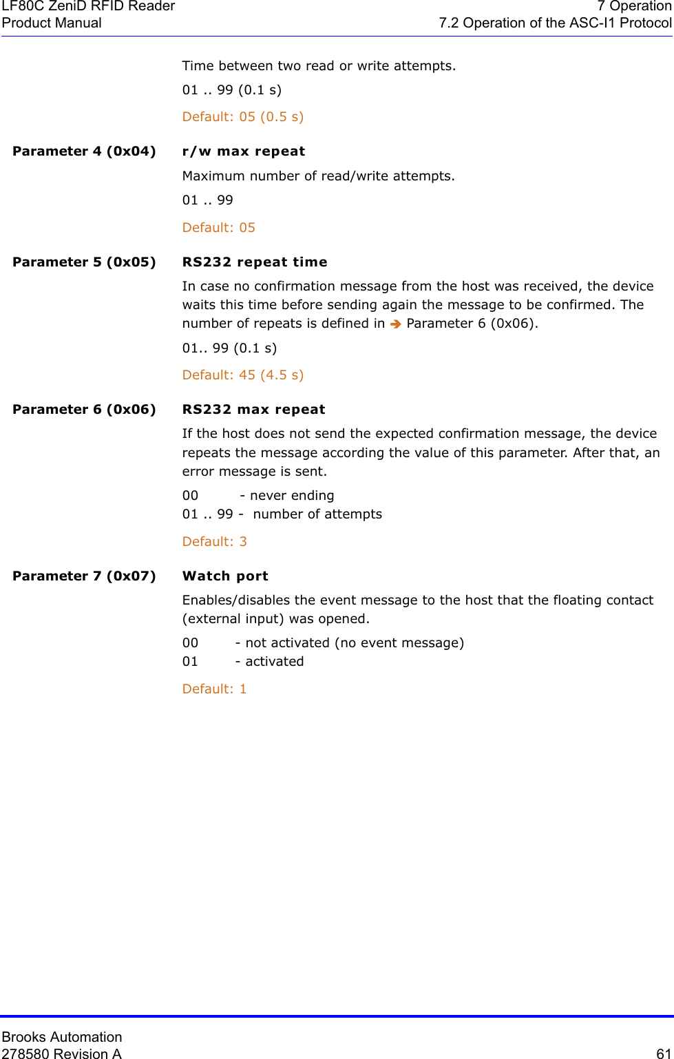
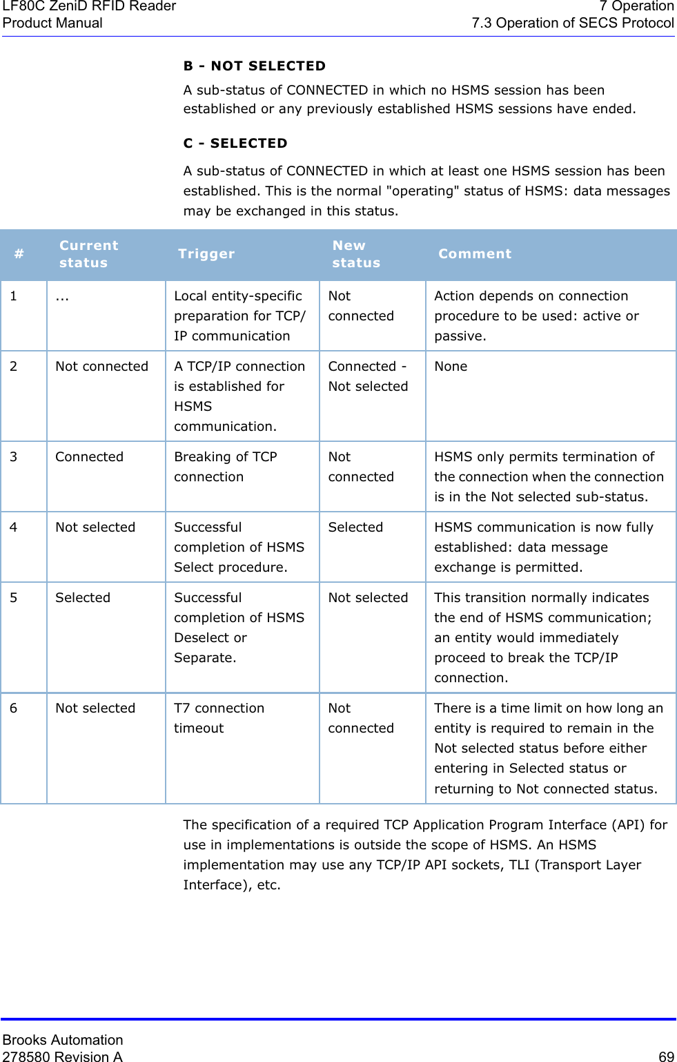
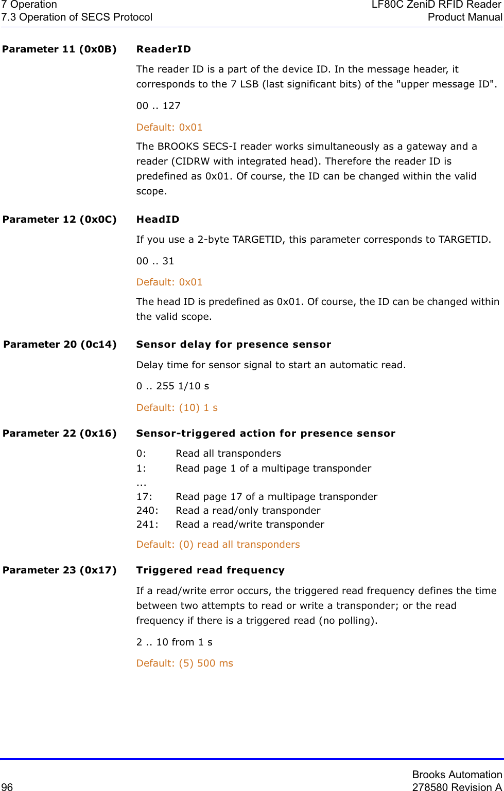
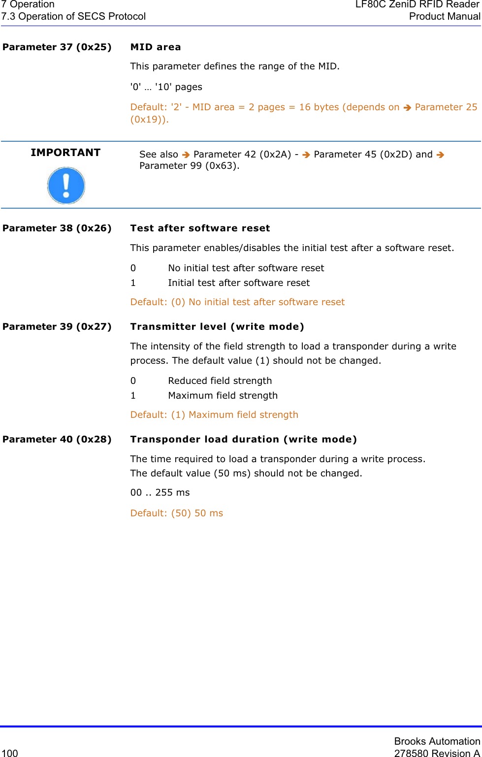
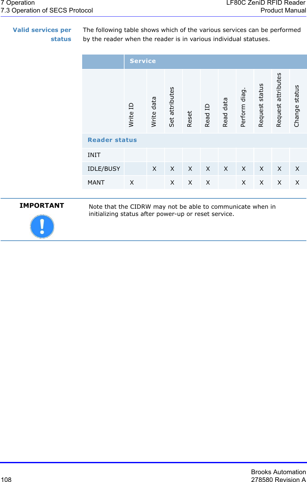
![Brooks Automation80 278580 Revision A7 Operation LF80C ZeniD RFID Reader7.3 Operation of SECS Protocol Product Manual14 Reserved15 Reserved16 ReservedWhere used S5F1For more information on error codes and the corresponding correcting actions please refer to Î Error Codes.Alarm textThe length of the alarm text is 0 to 40 characters. According to the reader version, status information about the sensor or sensors is also transmitted during a reader error message. The information should be interpreted as follows:ALTX[0] Initiator of an error message“0”: Sensor 0“1”: Sensor 1 (not available)“F”: Cannot be assignedALTX[1] Status of sensor 0“0”: Sensor not occupied“1”: Sensor is occupied“E”: Sensor status is not available“F”: Sensor not definedALTX[2] Status of sensor 1"0": Sensor not occupied"1": Sensor is occupied"E": Sensor state is not available"F": Sensor not definedALTX[3] ‘:’ a colon separates the alarm text from the sensor statusesWhere used S5F1ALTX Format:A[max40]](https://usermanual.wiki/Brooks-Automation/LF80BC1/User-Guide-3980249-Page-92.png)
![Brooks Automation278580 Revision A 81LF80C ZeniD RFID Reader 7 OperationProduct Manual 7.3 Operation of SECS ProtocolDescription: Identifier for an attribute for a specific type of object.CIDRW attribute definitions:"Configuration"… Number of heads"AlarmStatus” Current CIDRW sub-status of ALARM STATUS"OperationalStatus" Current CIDRW sub-status of OPERATING STATUS"SoftwareRevisionLevel" Revision (version) of software - 8-byte maximum"CarrierIDOffset" Offset of CID in CID field (MID area)"CarrierIDLength" Length of CID in CID field (MID area)"ECID_00" → parameter 0 - Î Gateway ID"ECID_01" → parameter 1 - Î Baudrate"ECID_02" → parameter 2 - Î Inter-character timeout T1"ECID_03" → parameter 3 - Î Block protocol timeout T2"ECID_04" → parameter 4 - Î Reply timeout T3"ECID_05" → parameter 5 - Î Inter-block timeout T4"ECID_06" → parameter 6 - Î Retry limit RTY"ECID_07" → parameter 7 - Î TARGETID high byte"ECID_08" → parameter 8 - Î TARGETID low byte"ECID_09" → parameter 9 - Î Heartbeat time1)"ECID_11" → parameter 11 -Î ReaderID"ECID_12" → parameter 12 - Î HeadID"ECID_20" → parameter 20 - Î Sensor delay for presence sensor"ECID_22" → parameter 22 - Î Sensor-triggered action for presence sensor"ECID_23" → parameter 23 - Î Triggered read frequency"ECID_24" → parameter 24 - Î r/w max repeat"ECID_25" → parameter 25 - Î Transponder type"ECID_26" → parameter 26 - Î Sensor activity"ECID_27" → parameter 27 - Î Watchport for presence sensorr"ECID_28" → parameter 28 - Î Transmitter level (read mode)"ECID_29" → parameter 29 - Î Transponder load duration (read mode)"ECID_30" → parameter 30 - Î r/w synchronize"ECID_31" → parameter 31 - Î Auto-adjust value (read mode)"ECID_32" → parameter 32 - Î Auto-adjust value (write mode)"ECID_33" → parameter 33 - Î Automatic antenna adjustment"ECID_34" → parameter 34 - Î Sensor type for presence sensor"ECID_35" → parameter 35 - Î Special features"ECID_36" → parameter 36 - Î Lock membrane keyboard"ECID_37" → parameter 37 - Î MID area"ECID_38" → parameter 38 - Î Test after software reset"ECID_39" → parameter 39 - Î Transmitter level (write mode)"ECID_40" → parameter 40 - Î Transponder load duration (write mode)ATTRID Format:A[max25]](https://usermanual.wiki/Brooks-Automation/LF80BC1/User-Guide-3980249-Page-93.png)
![Brooks Automation82 278580 Revision A7 Operation LF80C ZeniD RFID Reader7.3 Operation of SECS Protocol Product Manual"ECID_41" → parameter 41 - Î Delay time between read cycles"ECID_42" → parameter 42 - Î CarrierIDOffset"ECID_43" → parameter 43 - Î CarrierIDLength"ECID_44" → parameter 44 - Î FixedMID"ECID_45" → parameter 45 - Î MIDFormat"ECID_99" → parameter 99 - Î Customer codeHead attribute definitions: *"HeadStatus" The current status"HeadID" Head number 00-31 (2 digits)* With regard to an RFID Reader LF80C ZeniD, the head attribute definition "HeadStatus" is equal to the "OperationalStatus" of the CIDRW. The "HeadID" is also 01 and equal to the CIDRW "Configuration" attribute. Where used S18F1, S18F3Description: Value of the specified attribute.CIDRW attribute definitions:"Configuration” Number of heads "01""AlarmStatus” Current CIDRW sub-status of ALARM STATUS "0" …NO "1" …ALARMS"OperationalStatus" Current CIDRW sub-status of OPERATING"IDLE” … Reader in IDLE mode"BUSY” … Reader is busy"MANT" … Maintenance mode"SoftwareRevisionLevel" Revision (version) of Software - 8-byte maximumECID_00 to ECID_45 see data item ECV parameters 0 - 45ATTRVAL Format:A[max4]](https://usermanual.wiki/Brooks-Automation/LF80BC1/User-Guide-3980249-Page-94.png)
![Brooks Automation278580 Revision A 83LF80C ZeniD RFID Reader 7 OperationProduct Manual 7.3 Operation of SECS ProtocolHead attribute definitions:"HeadStatus" The current status"IDLE" ... Reader in IDLE mode"BUSY" ... Reader is busy"NOOP" ... Not operating"HeadID" Head number 00-31 (2 digits)"00" ... Reader 0"31" ... Reader 31Where used S18F2, S18F3Description Status request value"OP" ... Operating status"MT" ... Maintenance statusWhere used S18F13Description A vector or string of unformatted data.Multipage transponder DATA area depends on the MID area,can be page 1 - page 17 Read/write transponder DATA correspond to 8 byte MIDRead/only transponder DATA correspond to 8 byte MIDWhere used S18F6, S18F7Description Total bytes to be sent.The DATALENGTH corresponds to the quantity of bytes that are to be read or written. The valid range depends on the length of the MID area (Î Parameter 37 (0x25)).Where used S18F5, S18F7CPVAL Format: A[]DATA Format: A[]DATALENGTH Format: U2](https://usermanual.wiki/Brooks-Automation/LF80BC1/User-Guide-3980249-Page-95.png)
![Brooks Automation84 278580 Revision A7 Operation LF80C ZeniD RFID Reader7.3 Operation of SECS Protocol Product ManualDescription Used to identify the data requested.The DATASEG corresponds to the page number (PAGEID) of multipage, read/only and read/write transponders."00" First page of any type of transponder or first page of DATA area in case of a multipage transponder.Multipage-transponder (page 1 to page 17):Start the reading or writing on the following page of a multipage transponder:..."01" page 1 "81" Locked page 1... ..."11" page 17 "91" Locked page 17Read/only transponder "F0" Read only the one pageRead/write transponder "F1" Read or write only the one pageWhere used S18F5, S18F7Acknowledge code for new reader constant0 ... Parameter was set successfully1 ... Parameter could not be setWhere used S2F16Parameter number of reader (see data item ECV)Where used S2F13, S2F15Reader parameter definition. The values are displayed as decimal values, see Î Parameters.DATASEG Format:A[2]EAC Format: B[1]ECID Format: U1ECV Format: U1](https://usermanual.wiki/Brooks-Automation/LF80BC1/User-Guide-3980249-Page-96.png)
![Brooks Automation278580 Revision A 85LF80C ZeniD RFID Reader 7 OperationProduct Manual 7.3 Operation of SECS Protocol3 ... external LED4 ... OK5 ... Error6 ... Antenna7 ... Output12 ... Read13 ... Write14 ... TuningWhere used S18F13Description Status request value"On" Reader is on"Off" Reader is off"Flash" LED flashesWhere used S18F13Equipment model number.Where used S1F2Material format code.20: The material port number corresponds to the sensor number and statusWhere used S3F5, S3F7SECS message block header associated with message block in error.Where used S9F1, S9F3, S9F5, S9F7, S9F9LEDNR Format: A[]LEDSTATE Format: A[]MDLN Format: A[6]MF Format: B[1]MHEAD Format: B[10]](https://usermanual.wiki/Brooks-Automation/LF80BC1/User-Guide-3980249-Page-97.png)
![Brooks Automation86 278580 Revision A7 Operation LF80C ZeniD RFID Reader7.3 Operation of SECS Protocol Product ManualDescription Material IDDepending on the type of transponder, it is possible to modify the length of the MID.Multipage transponder MID can be set from "0" (no MID) to "10" (MID occupies the first 10 pages (writeable))Read/write transponder MID corresponds to DATA (writeable)Read/only transponder MID corresponds to DATA (fix)Where used S18F10, S18F11 Material ID acknowledge code0 Material ID acknowledged; the presence sensor was the initiator1 Not defined 2 Material ID acknowledged - reaction on externally triggered action; the message cannot be related to any sensor>2 Material ID not acknowledgedThe data item port number PTN indicates the initiator. Where used S3F14, S3F68Material ID acknowledge code2 Acknowledge, will send MID later in S3F13Where used S3F12Acknowledge code for OFF-LINE request.0 OFF-LINE acknowledge (reader is offline)Where used S1F16MID Format: AMIDAC Format: B[1]MIDRA Format: B[1]OFLACK Format: B[1]](https://usermanual.wiki/Brooks-Automation/LF80BC1/User-Guide-3980249-Page-98.png)
![Brooks Automation278580 Revision A 87LF80C ZeniD RFID Reader 7 OperationProduct Manual 7.3 Operation of SECS ProtocolAcknowledge code for ON-LINE request.0 ON-LINE accepted (reader is online)Where used S1F18Page number of multipage, read/only and read/write transponders0x00 : First page of the data area of a multipage transponder.Multipage transponder (pages 1 to 17):If only one page of the multipage transponder is read, note the following:0x01 : (1) page 1 0x81 : (129) locked page 1... ...0x11 : (17) page 17 0x91 : (146) locked page 17Read-only transponder:0xF0 : (240) Read one page onlyRead/write transponder:0xF1 : (241) Read or write one page onlyWhere used S3F11The transponder data that has been read or will be written. The PAGEDATA corresponds to the value of a transponder page.PAGEDATA [0] Corresponds to the page number. The value of the page number is displayed in the data item "PAGE_ID". PAGEDATA [1] The 8 bytes (one page) of the transponder ID follow.PAGEDATA [8]Where used S3F7, S3F12, S3F13, S3F65ONLACK Format: B[1]PAGE_ID Format: B[1]PAGEDATA Format: B[9]](https://usermanual.wiki/Brooks-Automation/LF80BC1/User-Guide-3980249-Page-99.png)
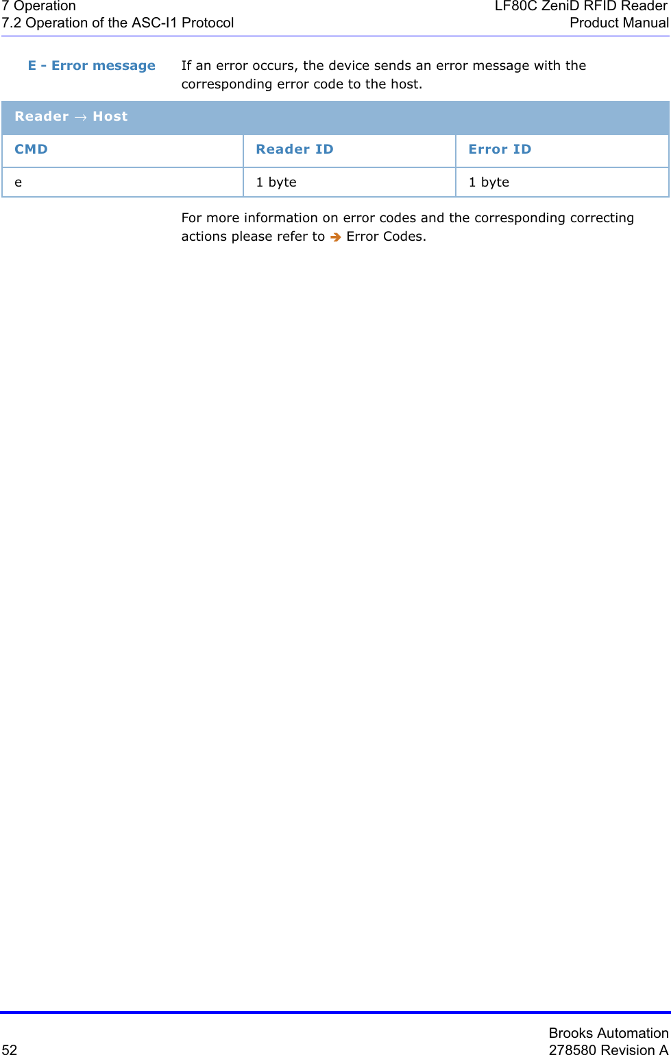
![Brooks Automation88 278580 Revision A7 Operation LF80C ZeniD RFID Reader7.3 Operation of SECS Protocol Product ManualDescription Preventive maintenance information"NE" … Normal execution"MR" … Maintenance requiredWhere used S18F2, S18F4, S18F8, S18F10, S18F12, S18F14Information about the status of up to two sensors and the initiator of the message.The second sensor is not implemented yet.For special applications, the reading process of the RFID reader is triggered by two sensors. In this case it is necessary to distinguish between the two sensors. The initiator represents the number of the sensor that has caused the message.Default: Only sensor 0 is defined.Sensor 0: bit 0 - bit 2The current status of sensor 0 is described in three bits.0 Sensor not occupied1 Sensor occupied7 Sensor not definedSensor 1: bit 3 - bit 5 (defined for future developments)The current status of sensor 1 is described in three bits.0 Sensor not occupied1 Sensor occupied7 Sensor not definedInitiator: bit 6 - bit 7The initiator represents the number of the sensor that has caused the message. 0Sensor 01 Sensor 1 (not implemented yet)3 Cannot be assignedWhere used S3F5, S3F7, S3F12, S3F13, S3F67PM Information Format: A[2]PTN Format: B[1]Initiator Sensor 1 Sensor 0Bit 7 ... bit 0](https://usermanual.wiki/Brooks-Automation/LF80BC1/User-Guide-3980249-Page-100.png)
![Brooks Automation278580 Revision A 89LF80C ZeniD RFID Reader 7 OperationProduct Manual 7.3 Operation of SECS ProtocolReset acknowledge code0 … Reset could be done1 … Reset could not be doneWhere used S2F20Reset code1… Power-up reset2 … Software reset Where used S2F19Stored SECS message block header. Only the last message is stored, which must still be confirmed by the host. Where used S9F9Software version.Where used S1F2RAC Format: B[1]RIC Format: B[1]SHEAD Format: B[10]SOFTREV Format: A[max 6]](https://usermanual.wiki/Brooks-Automation/LF80BC1/User-Guide-3980249-Page-101.png)
![Brooks Automation90 278580 Revision A7 Operation LF80C ZeniD RFID Reader7.3 Operation of SECS Protocol Product ManualDescription: Result information on the status of the request concerning the service request."NO" Normal operationIndicates the success of the requested action."EE" Execute errorCannot read tag data. Cannot read ID sequence.However, equipment is normal."CE" Communication errorSyntax error of message or message format or value."HE" Hardware errorID reader/writer head fault, ID reader/writer head is powered off."TE" Tag errorWhere used S18F2, S18F4, S18F6, S18F8, S18F10, S18F12, S18F14Description: Indicates an action to be performed by the subsystem.Used to differentiate between the different subsystem commands indicated."ChangeStatus" … Change status"GetStatus" … Get status"Reset" … Reset CIDRW"PerformDiagnostics"… Perform diagnostics"DefaultParams" … Reset default parameter*"FactorySettingParams" … Reset factory settings and default parameter“ADJUST“ … Automatic antenna calibration (parameter 33)"SetLED“ … Set LED*Where used S18F13 SSACK Format: A[2]SSCMD Format: A[max 18]](https://usermanual.wiki/Brooks-Automation/LF80BC1/User-Guide-3980249-Page-102.png)
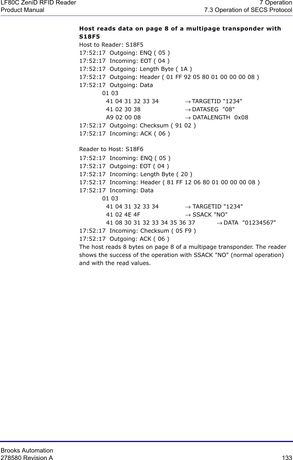
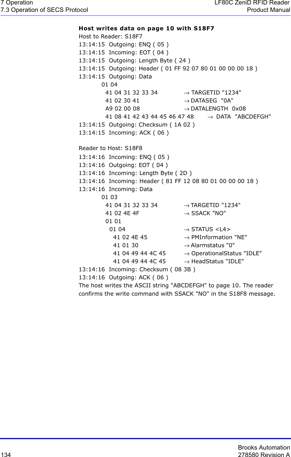
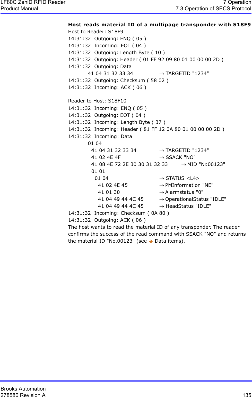
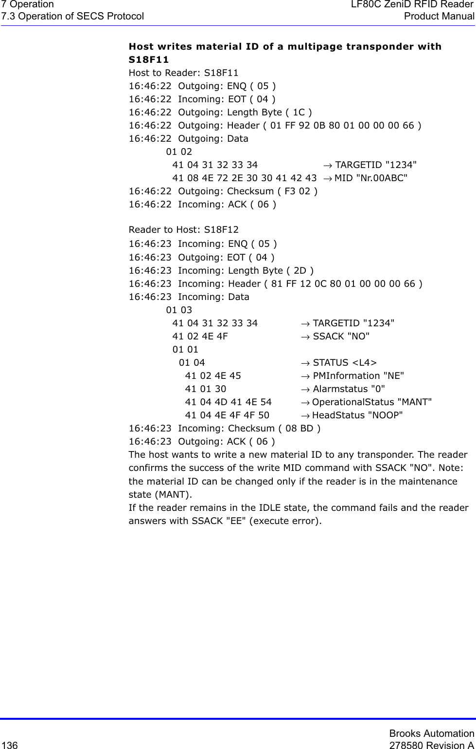
![Brooks Automation278580 Revision A 91LF80C ZeniD RFID Reader 7 OperationProduct Manual 7.3 Operation of SECS ProtocolDescription Provides status information of a subsystem component.Consists of PM Information and the current values of the CIDRW attributes AlarmStatus, OperatingStatus, and HeadStatus.List of a Status L,4 <PMInformation> <AlarmStatus> <OperatingStatus> <HeadStatus>For data items OperatingStatus and HeadStatus, see data item ATTRVAL.Where used S18F2, S18F4, S18F8, S18F10, S18F12, S18F14Description Identifies where a request for action or data is to be applied. Alternatively, you can use the HeadID.See also reader parameter definitions (data item ECV) parameter 7, 8 and 12.The 4 ASCII character TARGETID is changeable (only changeable for LF80C devices), and defined in parameter 7 and 8 ("ECID_07", "ECICD_08").The 2 ASCII character HeadID is changeable, and defined in parameter 12 ('ECID_12').Where used S18F1, S18F3, S18F5, S18F7, S18F9, S18F11, S18F13STATUS Format: A[2]TARGETID Format: A[max 4]](https://usermanual.wiki/Brooks-Automation/LF80BC1/User-Guide-3980249-Page-103.png)
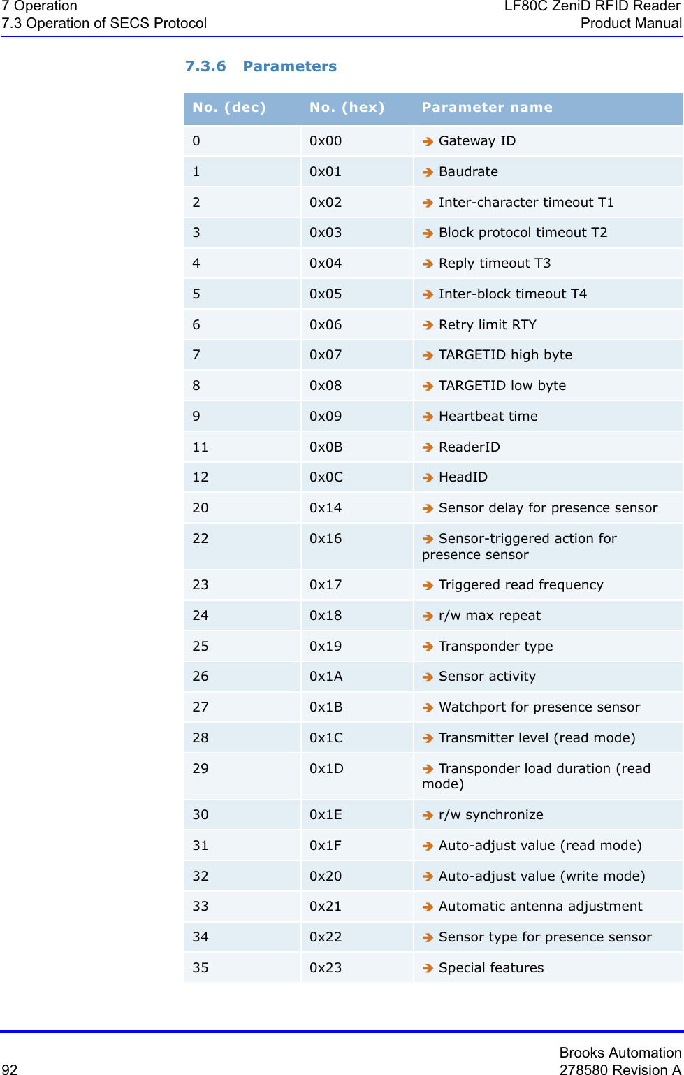
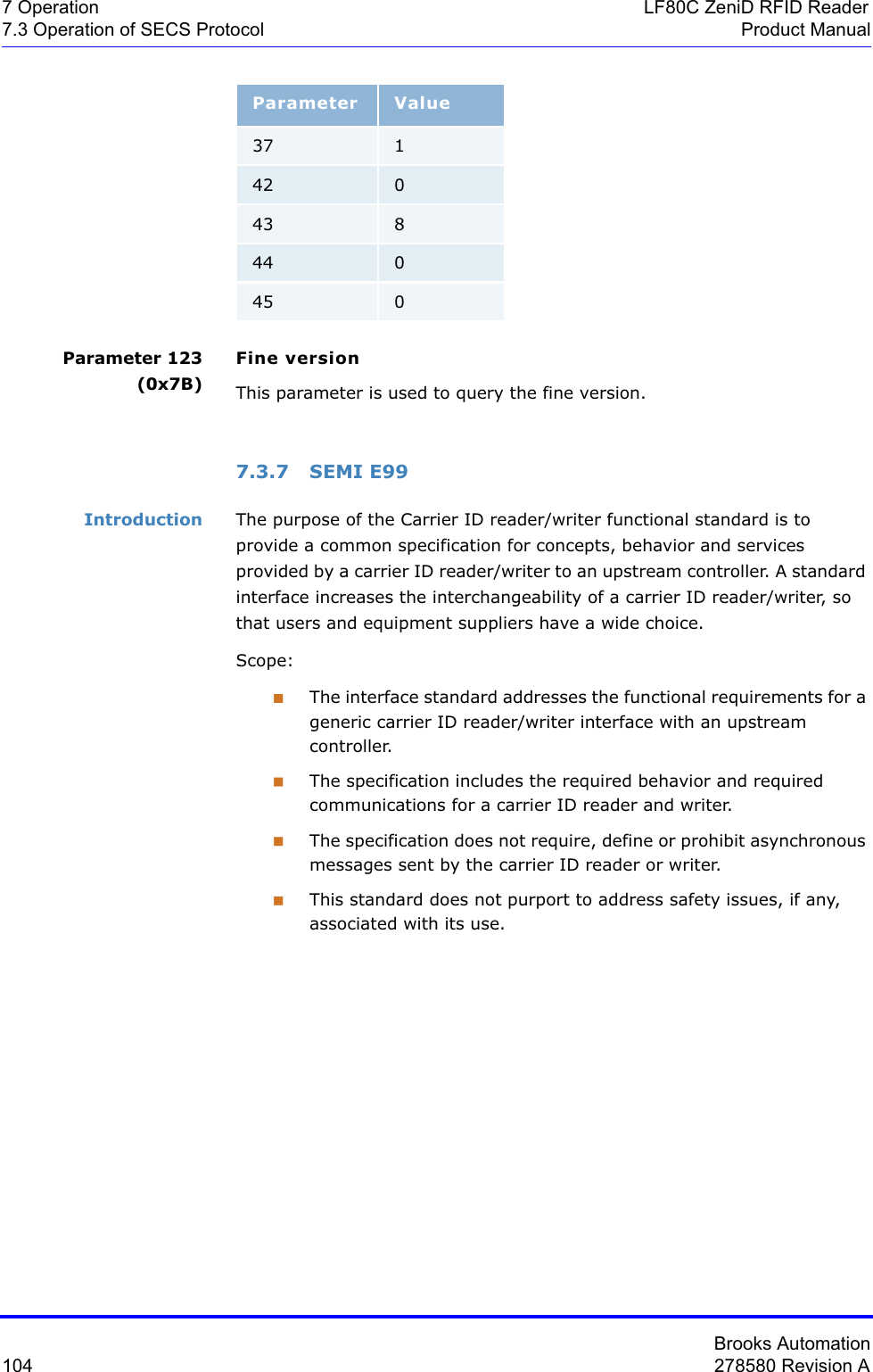
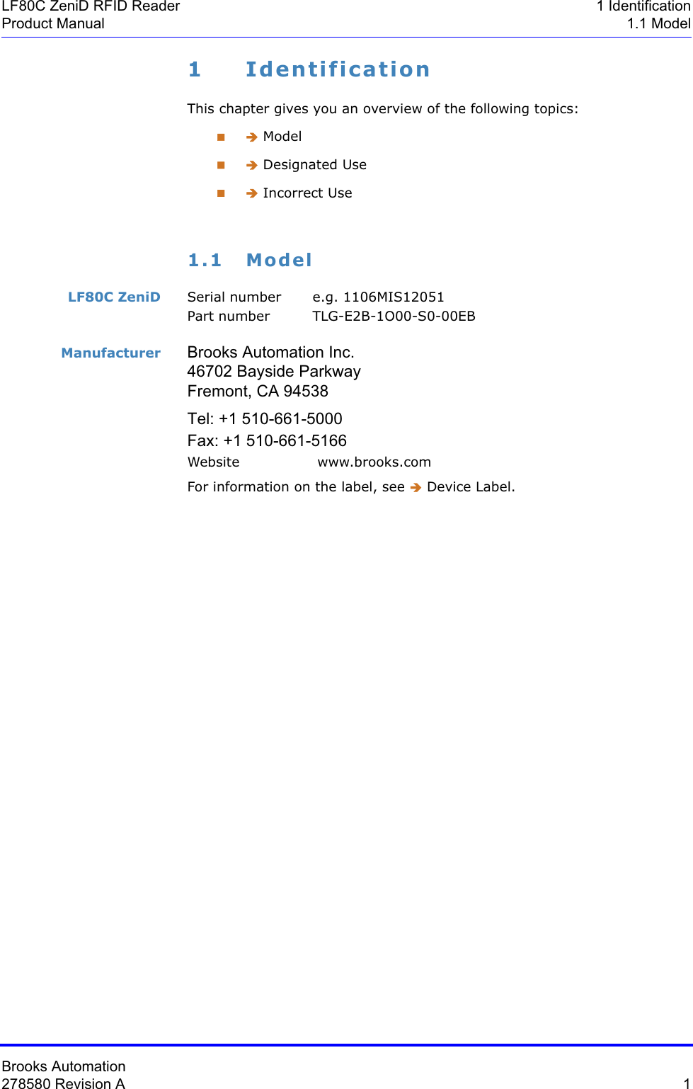
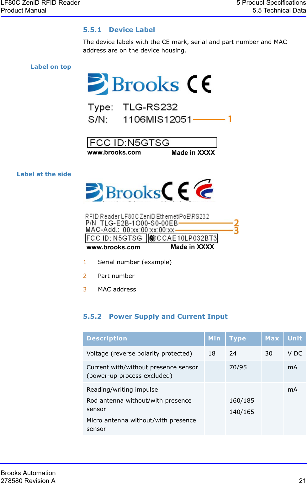
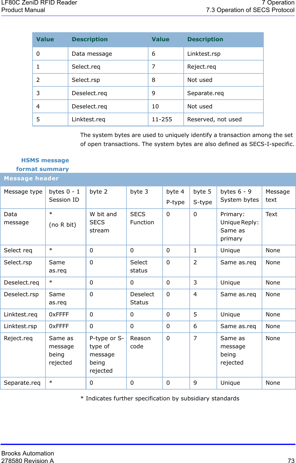
![Brooks Automation278580 Revision A 109LF80C ZeniD RFID Reader 7 OperationProduct Manual 7.3 Operation of SECS Protocol7.3.8 Message DetailsEquipment status S1F0: ABORT TRANSACTION (reader <-> host)Used instead of an expected reply to abort a transaction. Function 0 is defined in every stream and has the same meaning in every stream.S1F0 W . * Header onlyS1F1: ARE YOU THERE REQUEST (reader <-> host, reply)Establishes if the gateway/reader or host is online.S1F1 W . * Header onlyS1F2: ON-LINE DATA (host -> reader)The host signals that it is online.S1F2 <L[2] <A[6]MDLN > <A[6]SOFTREV > >S1F2: ON-LINE (reader -> host)The reader signals that it is online.S1F2 <L[2] <A[6]MDLN > <A[6]SOFTREV > >.S1F15: REQUEST OFF_LINE (host -> reader, reply)The reader is requested to change the communication status to offline.The reader can only be set online again by using message S1F17 (or reset S2F19); all other messages are aborted by the SxF0 message.S1F15 W. *Header onlyS1F16: OFFLINE ACKNOWLEDGE (reader -> host)Acknowledge.S1F16 <B[1]OFLACK>.](https://usermanual.wiki/Brooks-Automation/LF80BC1/User-Guide-3980249-Page-121.png)
![Brooks Automation110 278580 Revision A7 Operation LF80C ZeniD RFID Reader7.3 Operation of SECS Protocol Product ManualS1F17: REQUEST ON_LINE (host -> reader, reply)The reader is requested to change the communication status to online.S1F17 W. *Header onlyS1F18: ONLINE ACKNOWLEDGE (reader -> host)Acknowledge.S1F18 <B[1]ONLACK>.Equipment control S2F0: ABORT TRANSACTION (reader <-> host)Used instead of an expected reply to abort a transaction. Function 0 is defined in every stream and has the same meaning in every stream.S2F0 W. * Header onlyS2F13: EQUIPMENT CONSTANT REQUEST (host -> reader, reply)The host requests an attribute from the reader.S2F13 W <L[1] <U1[1] ECID>>.S2F14: EQUIPMENT CONSTANT DATA (reader -> host)The reader sends the requested attribute to the host.S2F14 <L[1] <U1[1] ECV> >.S2F15: NEW EQUIPMENT CONSTANT SENT (host -> reader, reply)The host changes a reader attribute.S2F15 W <L[1] <L[2] <U1[1] ECID> <U1[1] ECV> > >.](https://usermanual.wiki/Brooks-Automation/LF80BC1/User-Guide-3980249-Page-122.png)
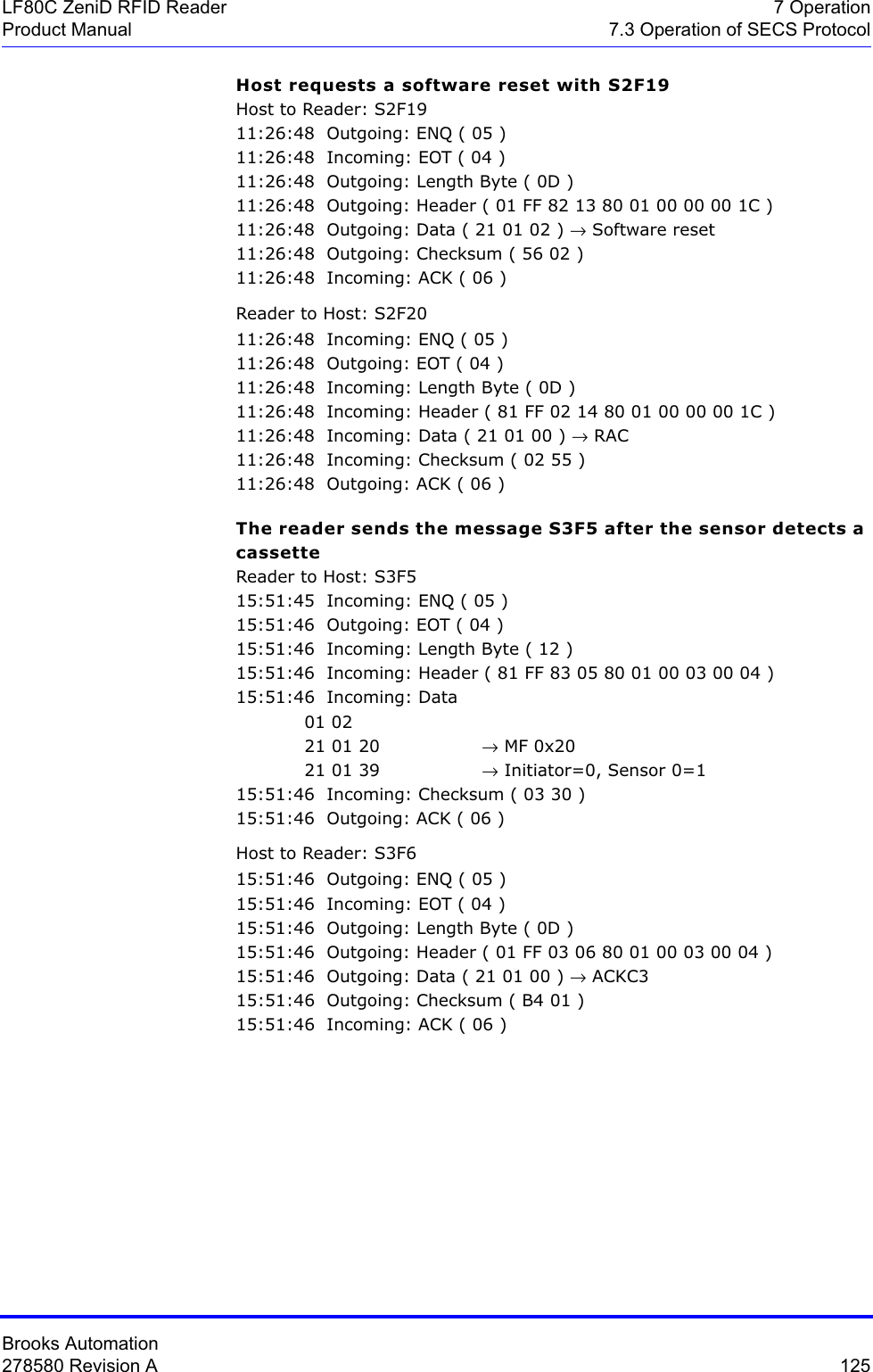
![Brooks Automation278580 Revision A 111LF80C ZeniD RFID Reader 7 OperationProduct Manual 7.3 Operation of SECS ProtocolS2F16: NEW EQUIPMENT CONSTANT ACKNOWLEDGE (reader -> host) The reader acknowledges the setting of the reader parameter.S2F16 <B[1] EAC>.S2F19: RESET SENT (host -> reader, reply)The host requests the reader to reset the hardware and software.If a heartbeat time is set (Î Parameter 9 (0x09)), the reader sends an S1F1 message when the reset is finished. The power-up reset requires a few seconds.S2F19 W <B[1] RIC>.S2F20: RESET ACKNOWLEDGE (reader -> host)The reader acknowledges the reset.This message is only displayed in case of a power-up reset (RIC=2).S2F20 <B[1] RAC>.Material status S3F0: ABORT TRANSACTION (reader <-> host)Used instead of an expected reply to abort a transaction. Function 0 is defined in every stream and has the same meaning in every stream.S3F0 W. * Header OnlyS3F5: CASSETTE FOUND SENT (reader -> host, reply)The reader sends the information that a cassette was detected by the presence sensor. This message is sent only if a sensor is connected and activated (see Î Parameter 27 (0x1B) and Î Parameter 26 (0x1A)).S3F5 W. <L[2] <B[1] MF> <B[1] PTN>>.S3F6: CASSETTE FOUND ACKNOWLEDGE (host -> reader)The host acknowledges the cassette found message.S3F6 <B[1] ACKC3>.](https://usermanual.wiki/Brooks-Automation/LF80BC1/User-Guide-3980249-Page-123.png)
![Brooks Automation112 278580 Revision A7 Operation LF80C ZeniD RFID Reader7.3 Operation of SECS Protocol Product ManualS3F7: CASSETTE LOST SEND (reader -> host, reply)The reader sends the information that the cassette was removed from the I/O port (presence sensor).This message is sent only if a sensor is connected and activated (see ÎParameter 27 (0x1B)' and Î Parameter 26 (0x1A)). The PAGEDATA can be given only if the PAGEDATA that was read last is still available.S3F7 W. <L[3] <B[1] MF > <B[1] PTN > <B[9] PAGEDATA >* >.* a zero-length PAGEDATA indicates that no PAGEDATA is available (case of error)S3F8: CASSETTE LOST ACKNOWLEDGE (host -> reader)The host acknowledges the cassette lost message.S3F8 <B[1] ACKC3>.S3F11: READ MID AT I/O PORT (host -> reader, reply)The host requests the reader to read the PAGEDATA of the given PAGE_ID.S3F11 W <B[1] PAGE_ID>.S3F12: READ ACKNOWLEDGE (reader -> host)The reader only acknowledges the receipt of the reading command.The PAGEDATA is sent later.S3F12 <L[3] <B[1] PTN>* <B[1] MIDRA> <B[9] PAGEDATA>**>.* a zero-length PTN indicates that no PTN is available** a zero-length PAGEDATA indicates that no DATA is available](https://usermanual.wiki/Brooks-Automation/LF80BC1/User-Guide-3980249-Page-124.png)
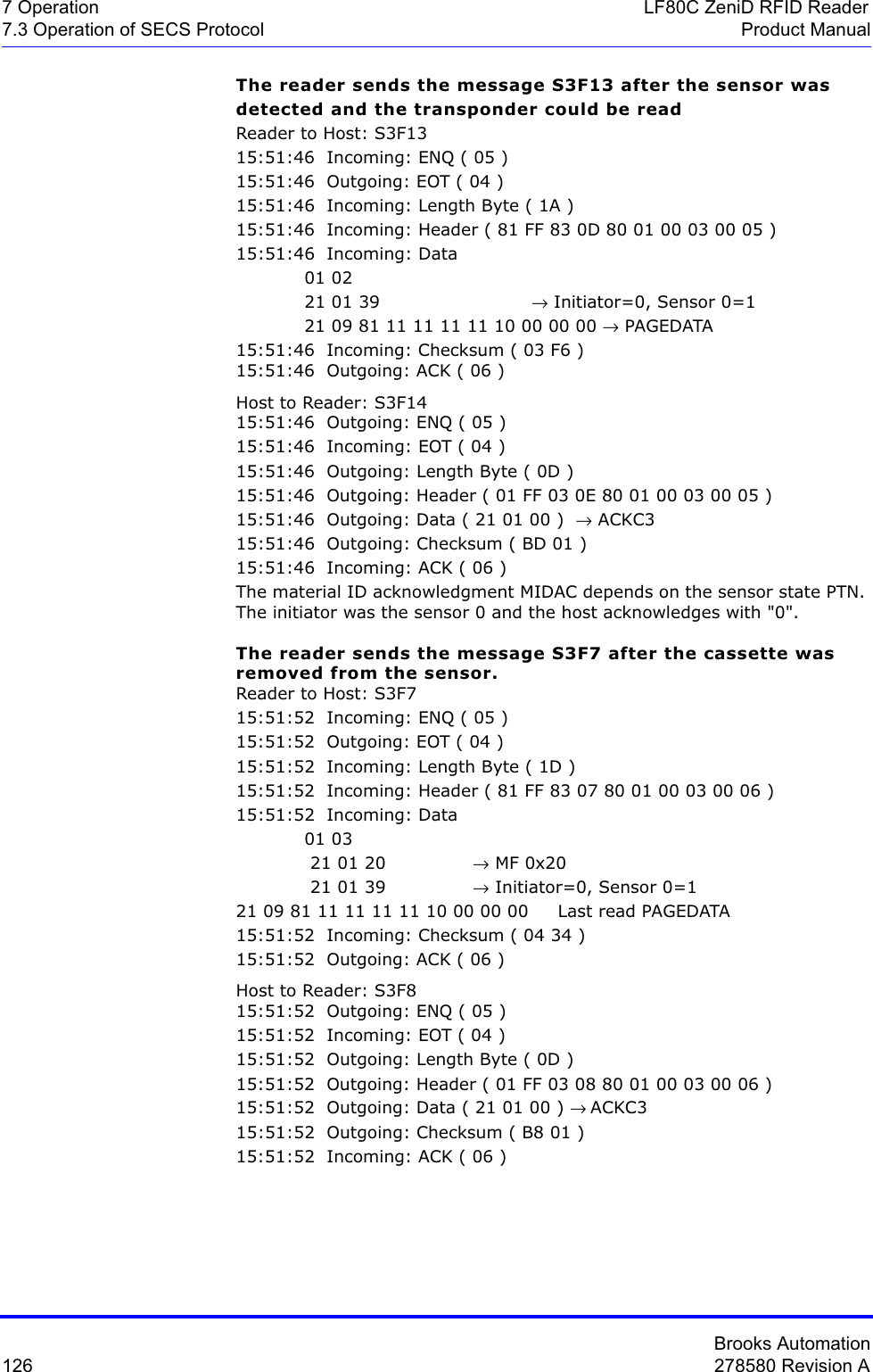
![Brooks Automation278580 Revision A 113LF80C ZeniD RFID Reader 7 OperationProduct Manual 7.3 Operation of SECS ProtocolS3F13: RETURN READ MID (reader -> host, reply)The reader sends the ID of the cassette at the I/O port to the host.S3F13 W <L[2] <B[1] PTN> <B[9] PAGEDATA >>.S3F14: MID ACKNOWLEDGE (host -> reader)The host acknowledges the received data.S3F14 <B[1] MIDAC>.S3F65: WRITE MID AT I/O PORT (host -> reader, reply)The host requests that the reader write the PAGEDATA.S3F65 W <B[9] PAGEDATA >S3F66: WRITE ACKNOWLEDGE (reader -> host)The reader only acknowledges the receipt of the write command.The write acknowledge is sent later.S3F66 <L[2] <B[1] MIDRA> <B[9] PAGEDATA > >.S3F67: RETURN WRITE SUCCESS (reader -> host, reply)The reader reports the successful writing of the transponder. The reader sends information about the presence sensor.S3F67 W <B[1] PTN>.S3F68: WRITE SUCCESS ACKNOWLEDGE (host -> reader)The host acknowledges the received data.S3F68 <B[1] MIDAC>.](https://usermanual.wiki/Brooks-Automation/LF80BC1/User-Guide-3980249-Page-125.png)
![Brooks Automation114 278580 Revision A7 Operation LF80C ZeniD RFID Reader7.3 Operation of SECS Protocol Product ManualS3F73: LOCK MID AT I/O PORT (host -> reader, reply)The host requests the reader to lock the requested page.S3F73 W<B[1] PAGE_ID>.S3F74: LOCK ACKNOWLEDGE (reader -> host)The reader acknowledges the receipt of the locking command only.The locking acknowledgment is sent later.S3F74 <L[2] <B[1] MIDRA> <B[9] PAGEDATA > >.S3F75: RETURN LOCK SUCCESS (reader -> host, reply)The reader reports the successful locking of the given page. The reader sends information about the presence sensor.S3F75 W <B[1] PTN>.S3F76: LOCK SUCCESS ACKNOWLEDGE (host -> reader)The host acknowledges the receipt of the lock success message (S3F75).S3F76 <B[1] MIDAC>.ATTENTION Locking a transponder page is permanent.You cannot unlock a transponder page.](https://usermanual.wiki/Brooks-Automation/LF80BC1/User-Guide-3980249-Page-126.png)
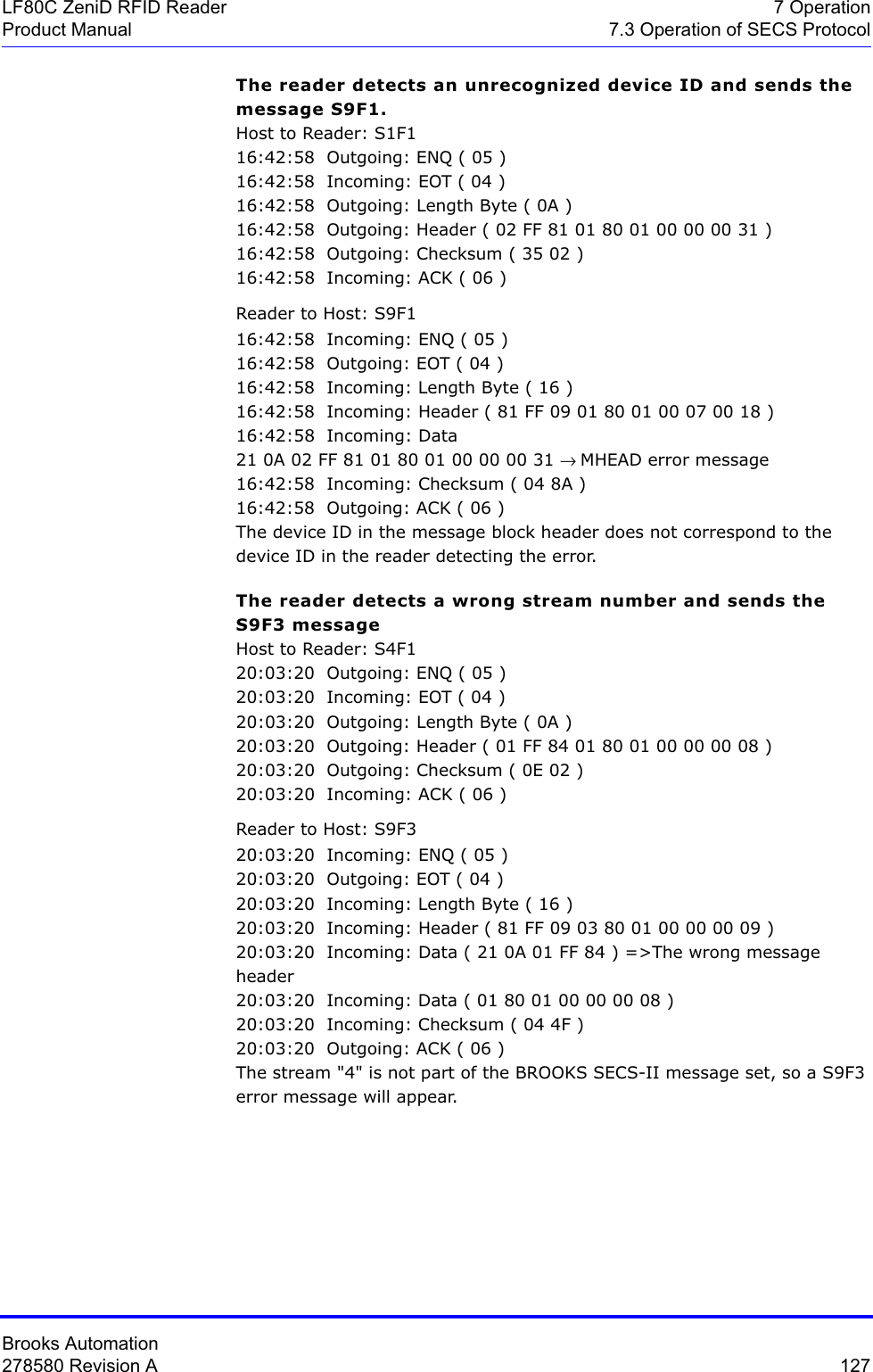
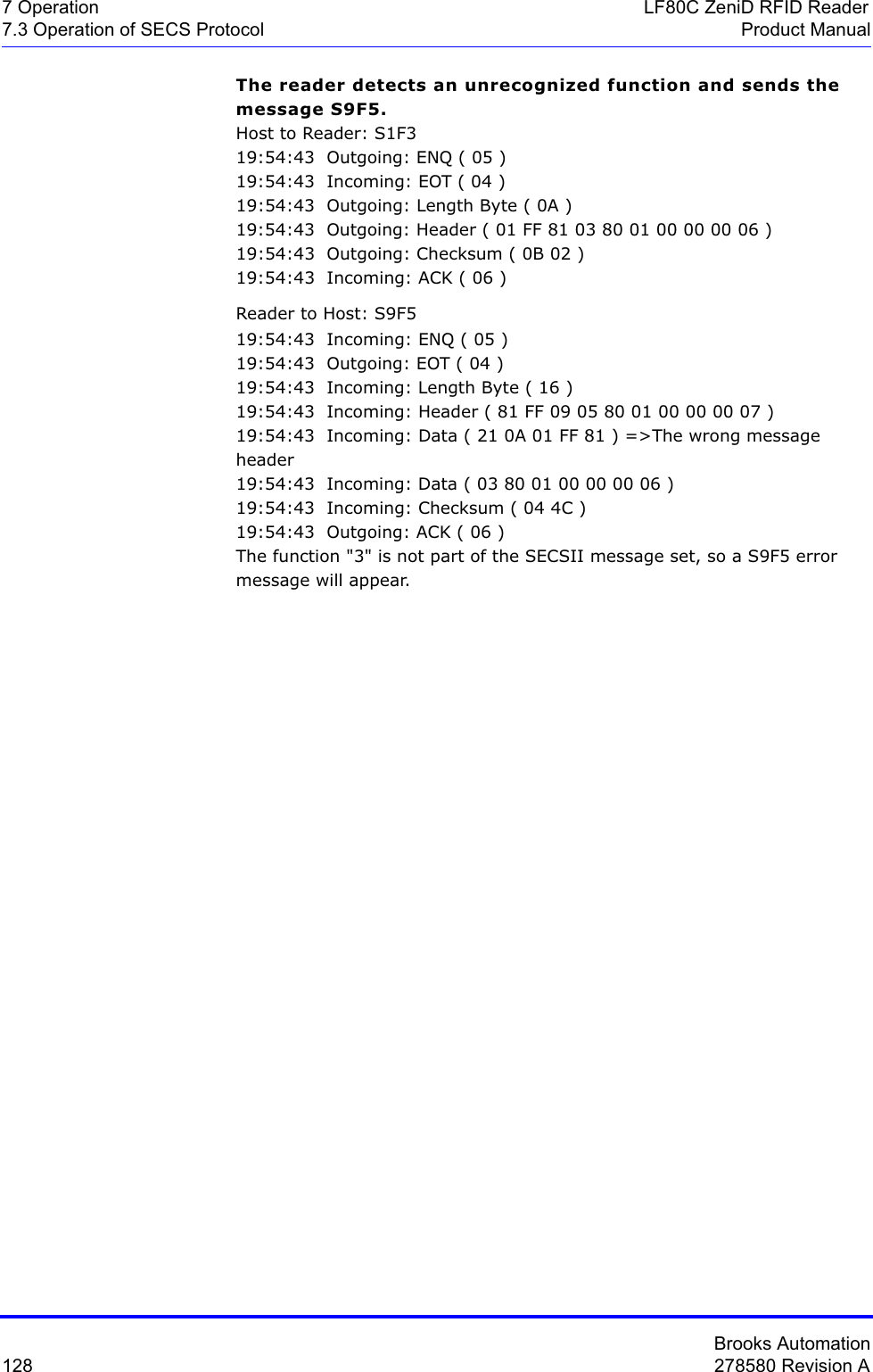
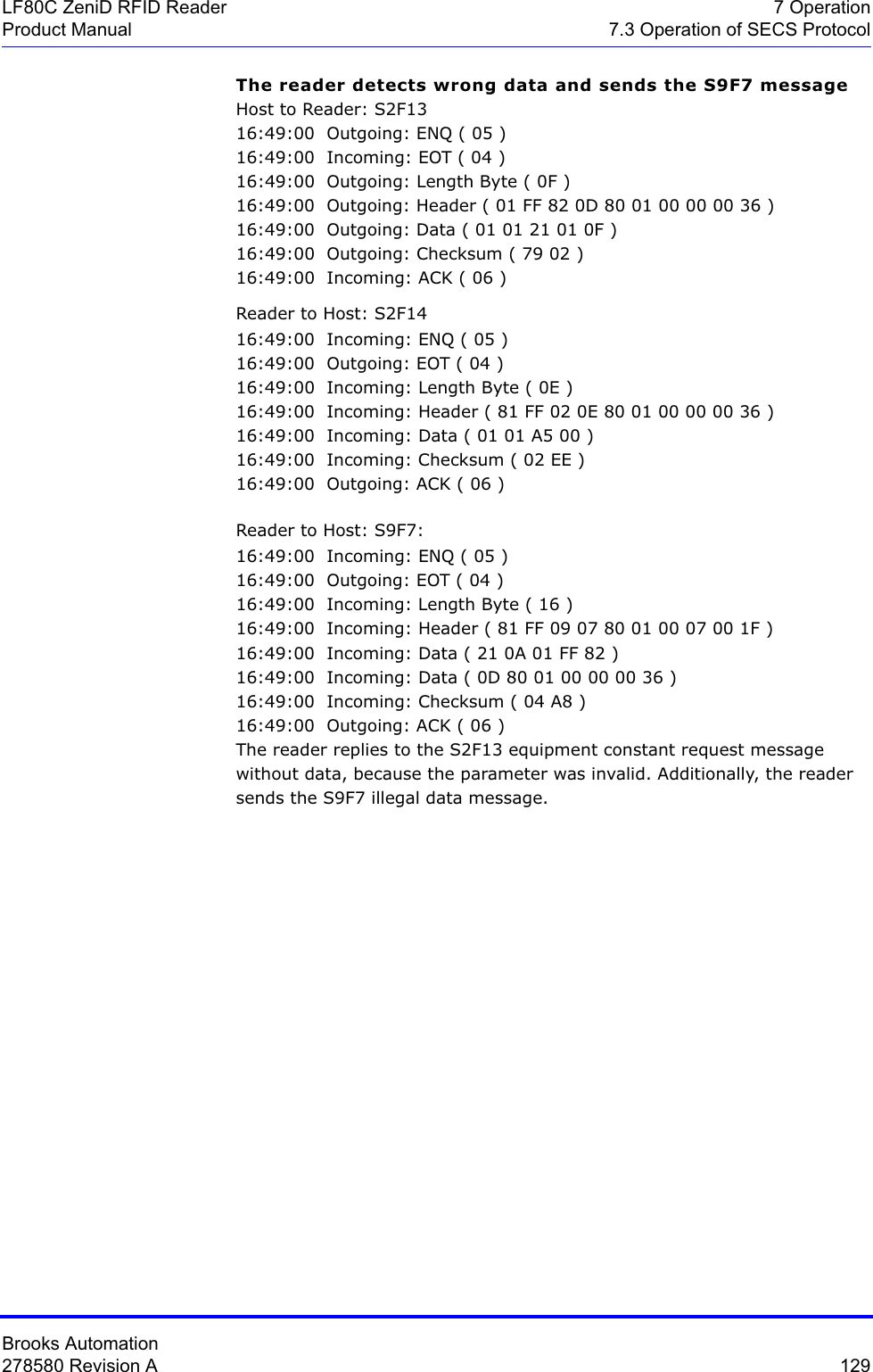
![Brooks Automation278580 Revision A 115LF80C ZeniD RFID Reader 7 OperationProduct Manual 7.3 Operation of SECS ProtocolException handling S5F0: ABORT TRANSACTION (reader <-> host)Used instead of an expected reply to abort a transaction. Function 0 is defined in every stream and has the same meaning in every stream.S5F0 W . * Header onlyS5F1: GATEWAY READER ALARM REPORT SEND (reader -> host, reply)The reader reports all errors to the host.S5F1 W <L[3] <B[1] ALCD > * alarm code byte <B[1] ALID > * alarm ID <A[MAX 40] ALTX > * alarm text >. S5F2: ALARM REPORT ACKNOWLEDGE (host -> reader)The host acknowledges an alarm.S5F2 <B[1] ACKC5>.System errors S9F1: UNRECOGNIZED DEVICE ID (reader -> host)The device ID in the message block header does not correspond to expected device ID.S9F1<B[10] MHEAD > .S9F3: UNRECOGNIZED STREAM TYPE (reader -> host)The reader does not recognize the stream type in the message block header.S9F3< B[10] MHEAD > .S9F5: UNRECOGNIZED FUNCTION TYPE (reader -> host)The reader does not recognize the function number in the message block header.S9F5< B[10] MHEAD > .S9F7: ILLEGAL DATA (reader -> host)The reader does not recognize the data in the message.S9F7 < B[10] MHEAD > .](https://usermanual.wiki/Brooks-Automation/LF80BC1/User-Guide-3980249-Page-127.png)
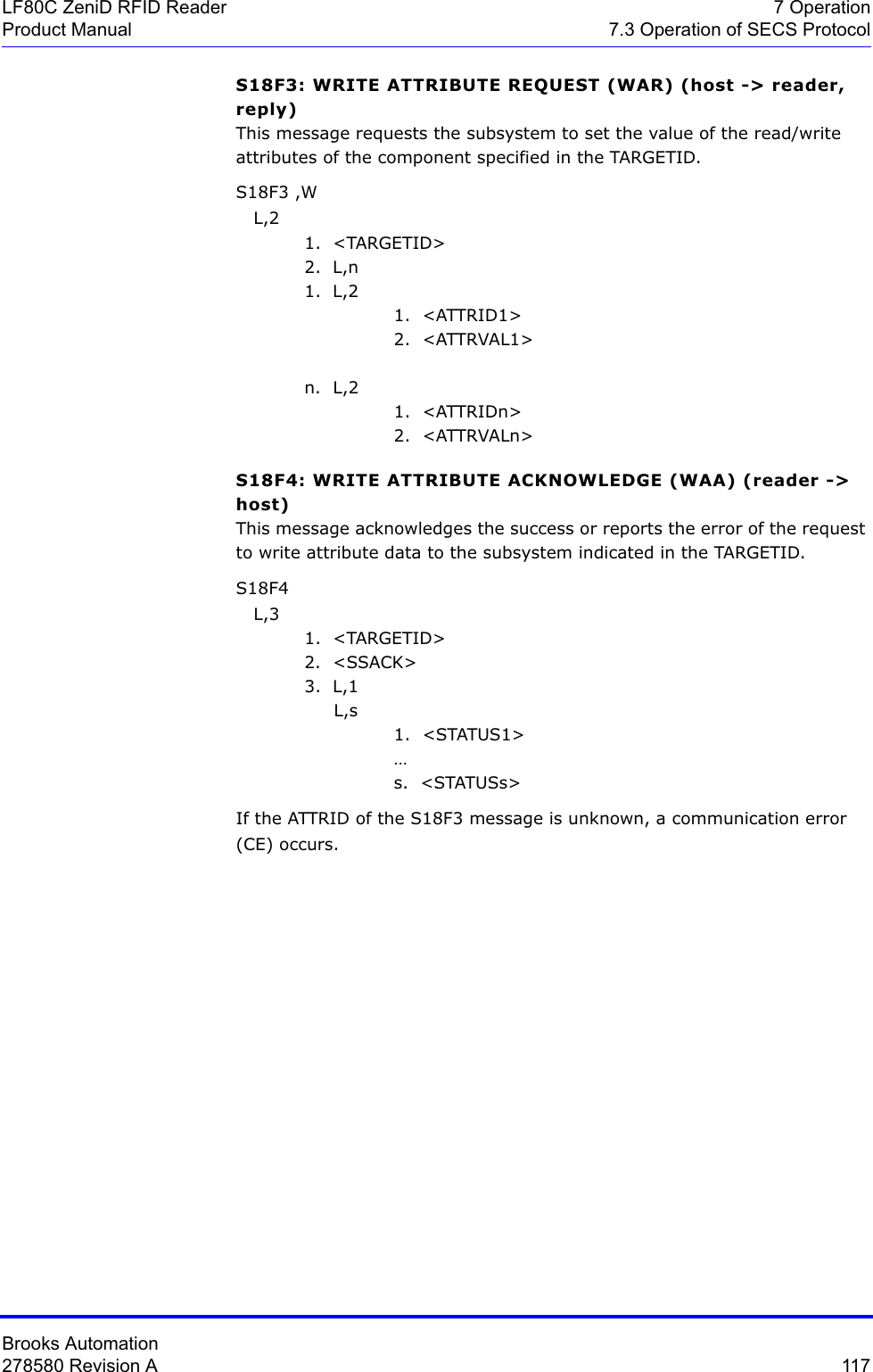
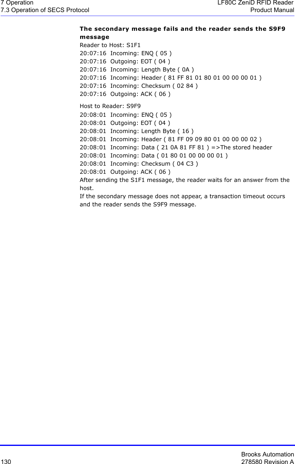
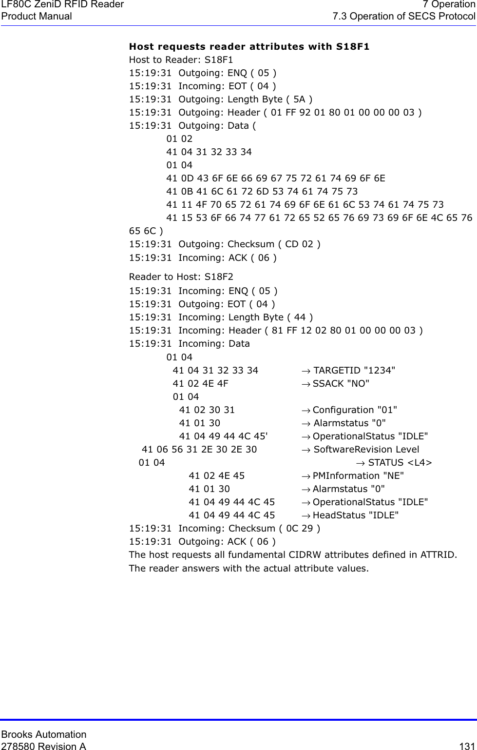
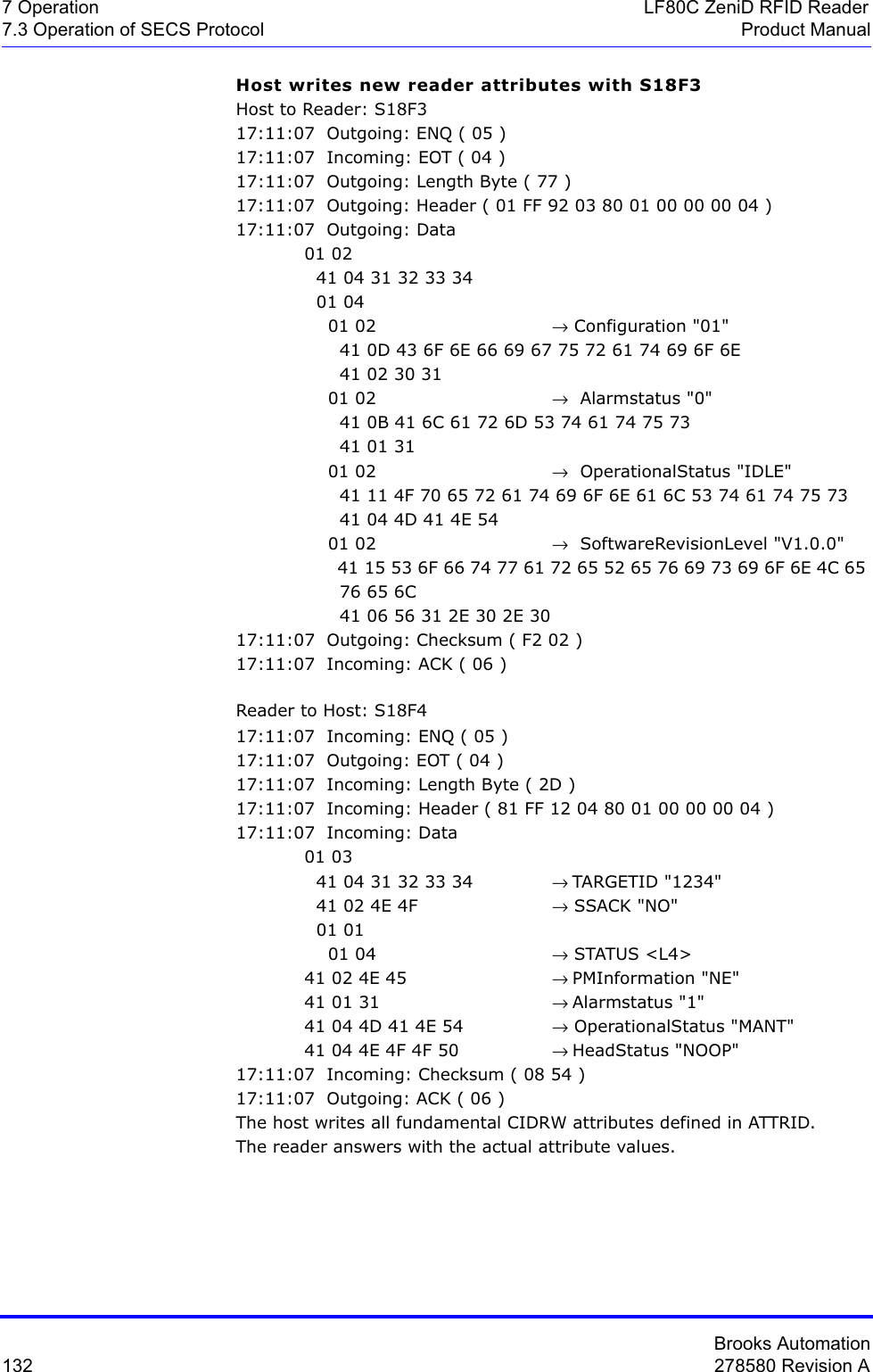
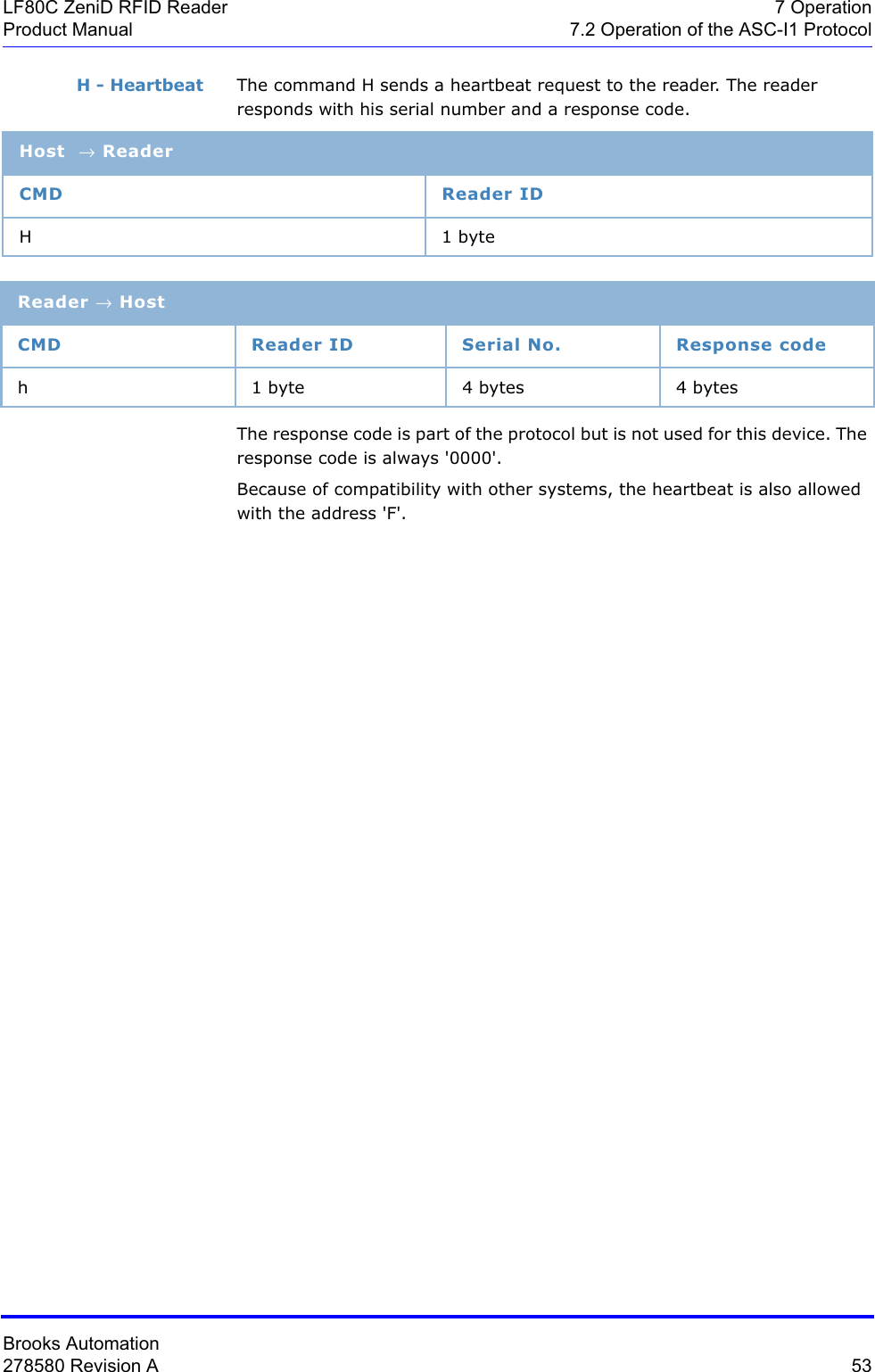
![Brooks Automation116 278580 Revision A7 Operation LF80C ZeniD RFID Reader7.3 Operation of SECS Protocol Product ManualS9F9: TRANSACTION TIMER TIMEOUT (reader -> host)This message indicates that a transaction timer has timed out and that the corresponding transaction was aborted. Only the last sent message (which must be confirmed by the host) is stored and its confirmation is temporally controlled.S9F9 < B[10] SHEAD > .For more information on error codes and the corresponding correcting actions please refer to .Subsystem control and dataS18F1: READ ATTRIBUTE REQUEST (RAR) (host -> reader, reply)This message requests the current values of specific attributes of the subsystem component indicated in the TARGETID.S18F1 WL,2 1. <TARGETID>2. L,n1. <ATTRID1> …n. <ATTRIDn>S18F2: READ ATTRIBUTE DATA (RAD) (reader -> host)This message returns the current values of the requested attributes and the current status of the requested component indicated in the TARGETID.S18F2 L,4 1. <TARGETID>2. <SSACK>3. L,n1. <ATTRVAL1> …n. <ATTRVALn>4. L,1L,s1. <STATUS1> …s. <STATUSs>If the ATTRID of the S18F1 message is unknown, the corresponding ATTRVAL has the value <nothing>.](https://usermanual.wiki/Brooks-Automation/LF80BC1/User-Guide-3980249-Page-128.png)