Brooks Automation SAF RFID Transponder Read/Write Station User Manual Short Description
Brooks Automation (Germany) GmbH RFID Division RFID Transponder Read/Write Station Short Description
Short Description

SA FOUP Read-Write Station – Stand Alone
Short Descsription

2
FOUP Read/Write Station – Stand Alone, Release 1.0
ID030042
Rev 08-2003
Printed in Germany
Subject to modifications
© 2003 Hermos Informatik GmbH
A Division of Brooks Automation
Gartenstrasse 19
D-95490 Mistelgau
Germany
Tel: +49 9279 991 910
Fax: +49 9279 991 900
E-mail: rfid.support@brooks.com

3
FOUP Read/Write Station – Stand Alone, Release 1.0
1 IMPORTANT NOTE 4
2 PRODUCT OVERVIEW 5
2.1 SA FOUP Read – Write Station ............................................. 5
2.2 Component RF Tag Reader.................................................... 6
2.3 Component Barcode Reader................................................... 6
3 INSTALLATION 7
3.1 Installation Environment ....................................................... 7
3.2 Qualified Installation Personnel............................................. 8
3.3 Unpacking............................................................................. 8
4 CONNECTIONS 9
4.1 Power Connection ................................................................. 9
4.2 RJ-45 Connector (Ethernet interface)..................................... 9
5 APPLICATION FLOW 10
6 TECHNICAL DATA 11

4
FOUP Read/Write Station – Stand Alone, Release 1.0
1 IMPORTANT NOTE
This device complies with Part 15 of the FCC rules. Operation is subject
to the following two conditions: (1) This device may not cause harmful
inteference, and (2) this device must accept any interference received,
including interference that may cause undesired operation.
CAUTION:
Any changes or modifications not expressly approved by the party
responsible for compliance could void the user’s authority to operate the
equipment.
5
FOUP Read/Write Station – Stand Alone, Release 1.0
2 PRODUCT OVERVIEW
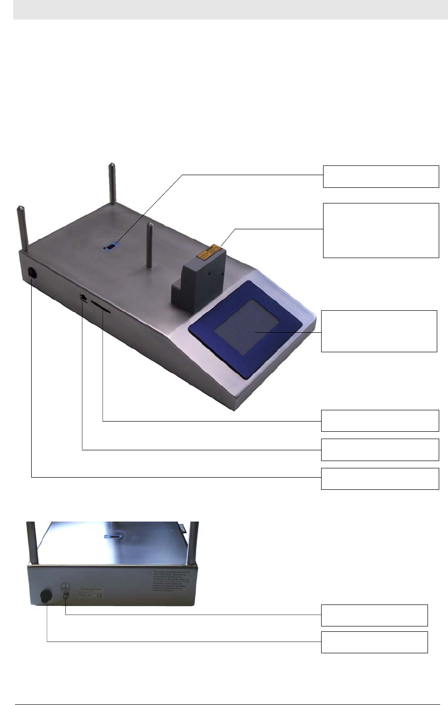
2.1 SA FOUP Read – Write Station
The unit is composed of a RF tag reader, a barcode reader, an optical
sensor, and a 240x128 pixel display with integrated touch screen (10x6
touch areas). It is used to read information from barcodes and write this
information to the RF tag. Therefore a FOUP must be placed on the
unit, which is detected by an optical sensor.
RJ45 - LAN
display with touch
screen
CF-Card slot
Barcode reader
and RFID antenna
optical sensor
p
ower supply
ground
p
ower switch

6
FOUP Read/Write Station – Stand Alone, Release 1.0
2.2 Component RF Tag Reader
The Transponder Reader System is a high-frequency identification
system that uses FM transmission. The basic item is a transponder that
works as a forgery-proof electronic identity disk.
The reading unit of the system sends an energy impulse via the
antenna. The capacitor of the passive, battery-free transponder is
charged by this impulse. After that, the transponder returns a signal
with the stored data. The total reading cycle takes less than 100 ms.
As a sight connection between the transponder and the reader is not
absolutely necessary, the transponder can also be identified through
non-metallic material.
The data received by the transponder reader are transmitted via the
serial interface in the unit.
2.3 Component Barcode Reader
The Barcode Reader is a device, which uses Laser light to read barcodes
over a distance between 45 and 175 mm. The sampling rate is about 500
per seconds. The wave length of the Laser diode is 650 nm and the
output power is 1,5 mW (CLASS 2 Laser). The user should avoid
staring directly into the beam.
7
FOUP Read/Write Station – Stand Alone, Release 1.0
3 INSTALLATION
3.1 Installation Environment
This device is designed for use in an indoor industrial
environment only. Installation is only permitted in an
environmental indoor climate with a constant
temperature of between 0°C and +50°C / 32°F and
122°F, humidity between 25% and 80%, and a maximum
temperature of +50°C / 122°F.
Do not install or use this device in or near water. Never
spill liquids of any kind onto the device. Should spillage
occur, unplug the device and have it checked by a
technician.
Do not install near heat sources such as radiators, heat
registers, stoves, or other apparatus (including
amplifiers) that produce heat. Do not install the device in
a flammable environment.
Never expose the device to intense changes in
temperature, otherwise condensation can develop inside
the device and cause damages.
Do not locate the device near overhead power lines or
other electric lights, or power circuits or where it can
encounter such circuits. When installing the device, take
extreme care not to encounter such circuits as they can
cause serious injury or death.
The device should not be used in the immediate vicinity
of electrical units (such as medical units, monitors,
telephones, televisions and energy-saver lamps),
magnetic data carriers, or metallic objects. This could
result in reduced reading/writing ranges.
Never use the device in potentially explosive areas (such
as paint shops).

8
FOUP Read/Write Station – Stand Alone, Release 1.0
Do not position the device in a location where it can
suffer from vibration or shock.
When the device is installed, the installation location
must be adequately illuminated.
Do not install the device during periods of lightning.
Ensure the installation location complies with FCC
requirements for human exposure to radio frequency.
When determining the assembly location, consider the
length of the antenna cable that will be used, and the
reading and writing range. See section
„Accessories/Antennas“ for further information.
3.2 Qualified Installation Personnel
The installation shall be carried out by specially trained personnel only.
If you are uncertain about the qualification, contact the manufacturer.
3.3 Unpacking
This device and its accessories were packed under clean room
conditions. To preserve these conditions, the device must be unpacked
under clean room conditions.
The packing material consists of cardboard and film. Dispose of these
materials separately in accordance with the relevant legislation in your
country.

9
FOUP Read/Write Station – Stand Alone, Release 1.0
4 CONNECTIONS
4.1 Power Connection
Built-in male plug, plastic (power supply)
The device can be connected to an interior DC power circuit or to a DC
adapter.
4.2 RJ-45 Connector (Ethernet interface)
The interface is used to connect the device to LAN network for update
the software only. Therefore a FTP program transmits the new files to
the flash memory of the station.
PIN Si
g
nal
1 +24V
2 0V
3
N
C
4
N
C
5
N
C
1
2
3
4
5

10
FOUP Read/Write Station – Stand Alone, Release 1.0
5 APPLICATION FLOW
To transfer the FOUP data from barcode label to the RF tag, the FOUP
have to be placed on the unit. The optical sensor detects the FOUP and
the station will be switched to operation mode. There are different
modes to transfer the data from barcode to RF tag.
The Manual Mode for reading the barcode and reading and writing the
tag independently from each other.
Automatic Mode and Full Automatic Mode are used to read the barcode
and then copy the data to the tag automatically.
In normal case the barcode ID will be read from the FOUP label. After
that the ID will be written to the RF tag at the FOUP. Then one or more
pages of the tag will be locked and the ID will be stored on a file on the
CF card.

11
FOUP Read/Write Station – Stand Alone, Release 1.0
6 TECHNICAL DATA
Operation temperature 0°C to 50°C / 32°F to 122°F
Stock temperature -25°C to 70°C / -13°F to 158°F
Ethernet Connector RJ-45
CF-Card min. 32MB
Voltage 18 … 30 VDC
Current typ. / max. 400 mA / 600 mA (24V)
Wight (without BCR) 7.100 g
RF Reader:
Transmitter frequency 134.2 kHz
Max. transmitting level in 3m distance 104 dBµV/m
Typ. period of charging impulse 50ms
Max. repeat of reading 4/s
Max. repeat of programming 2/s
Fuse type TR5 500mA (T)
Voltage 13 .. 24 VDC
Reading/writing impulse 160 mA (24V)
Barcode Reader (integrated):
Voltage 5VDC
Laser power max. 1,5mW
Laser Class 2
Sampling Mode Raster
Sampling Rate 500 / s
Voltage 5 VDC
Current max. 330 mA
Wight 130 g
Display (Graphic Device):
Pixels (Blue Line) 240 x 128
Touch Panel Fields 10 x 6
Voltage 5 VDC
Current 700 mA

12
FOUP Read/Write Station – Stand Alone, Release 1.0
Version Änderungen
Datum Autor
0.1 26.05.03 RW