Brooks Automation UF80 RFID UHF Reader User Manual Product Manual
Brooks Automation (Germany) GmbH RFID Division RFID UHF Reader Product Manual
Contents
- 1. User Manual
- 2. User Manual revision
User Manual
2ADIO&REQUENCY)$ENTIlCATION
DIO&
ENCY
NTIl
ON
2ADIO
DIO
QUEN
$EN
ATIO
2AD
2AD
EQU
Y)$E
lCA
2&)$
2
&)
$
$
2
2
2&
&
)$
)$
$
2
2
2&
2&
&)$
)$
$
English
Product Manual
RFID Reader UF80
The product manual must be read prior to the initial start-up. Observe the safety instructions!
Store for future use. This documentation is not subject to revisions.
ID120044 06/2012

This product manual corresponds with "Directive 1999/5/EC of the European Parliament
and the Council on radio equipment and telecommunications transmission equipment
and the mutual recognition of the conformity".
This product manual is addressed to the operating company who must pass it on to the
personnel responsible for installation, connection, use and repairs of the machine.
The plant manager must ensure that the information contained in this product manual and
in the accompanying documents has been read and understood.
The product manual must be stored in a place that is familiar and easily accessible to
employees and must be consulted whenever an employee is unsure of how to proceed.
The manufacturer does not assume any responsibility for injuries to persons or animals, or
damage to property or to the device arising from incorrect use or disregard or insufficient
consideration of the safety criteria contained in this product manual or based on
modifications of the device or the use of unsuitable spare parts.
The copyright for this product manual is held solely by
Brooks Automation (Germany) GmbH
RFID Division
Gartenstr. 19
95490 Mistelgau
Germany
or its legal successor.
Reproducing or circulating this product manual is only permitted with the exclusive
approval of the copyright holder. This also applies if only excerpts of the product
manual are copied or circulated. These requirements also apply for circulating the
product manual in digital form.
Status: June 2012
Information
Information
Archiving
Store the product manual in the vicinity of the device!
Always keep the product manual handy!
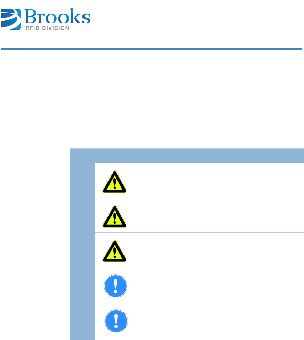
Symbols and signal words
The following symbols and signal words are used in this documentation. The
combination of a pictograph and a signal word classifies the respective safety
information. The symbol can vary depending on the type of danger.
Symbol Signal word Description
Death
DANGER This signal word must be used if death or
irreversible damage to health can occur if
the hazard information is not followed.
Risk of injury and
property damage
WARNING This signal word indicates bodily injuries
and property damage including injuries,
accidents, and health risks.
CAUTION This signal word indicates a risk of
property damage. In addition, there is a
slight risk of injuries.
No damage
ATTENTION This signal word warns of malfunctions
and may only be used if no damage to
health can occur.
IMPORTANT This signal word indicates cross-
references and ways in which operations
are facilitated. It excludes all risks of
property damage and injury risks.
Information
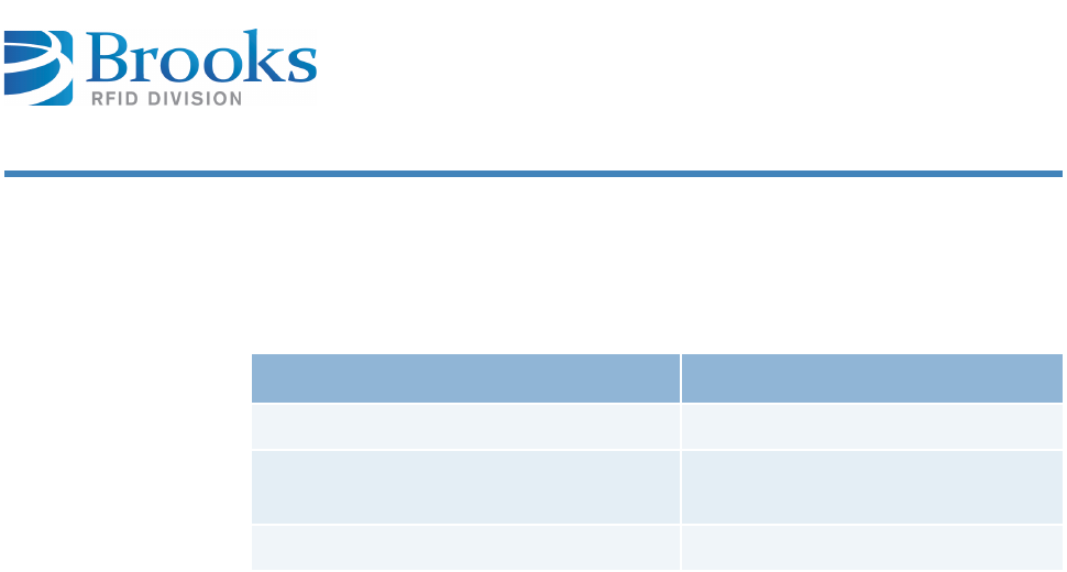
Target group
This product manual is addressed to personnel with the following areas of
responsibility:
Definition according to DIN EN 60204-1:
Instructed personnel
Persons who have been instructed and, if required, trained by a specialist as to
the tasks assigned to them, the possible risks of incorrect behavior and the
required safety equipment and safety measures.
Specialized personnel
Persons who can evaluate the work assigned to them and recognize possible risks
based on their specialized training, knowledge, experience and familiarity with
the relevant standards.
Area of responsibility Competence
Installation, transport and storage Specialized personnel
Commissioning, operation and
decommissioning
Instructed personnel
Troubleshooting Specialized personnel

Contents
1 Identification . . . . . . . . . . . . . . . . . . . . . . . . . 8
1.1 Designated use 8
1.2 Incorrect use 9
2 Declaration of Conformity . . . . . . . . . . . . . . . 10
3 General Instructions . . . . . . . . . . . . . . . . . . . 12
3.1 Warranty and liability 12
3.2 Objectives of the product manual 12
4 Safety Instructions . . . . . . . . . . . . . . . . . . . . 14
4.1 Area of application and symbols 14
4.1.1 Safety symbols – in compliance with DIN 4844-2 14
4.1.2 Warning symbols 15
4.1.3 Prohibition symbols 15
4.1.4 Other symbols 15
4.2 Obligations 16
4.2.1 Operating company’s obligations 16
4.2.2 Operating personnel’s obligations 16
4.3 ESD instructions 17
4.4 Residual risks 17
4.5 Additional information 18
5 Product Specifications . . . . . . . . . . . . . . . . . . 20
5.1 Function 20
5.2 Images 20
5.2.1 Side view 20
5.2.2 Top view 21
5.3 Description of the components 21
5.4 Technical data 22
6 Installation . . . . . . . . . . . . . . . . . . . . . . . . . . 24
6.1 Safety instructions 24
6.2 Qualified installation personnel 26
6.3 Unpacking 26
6.4 Assembly of the device 27
6.5 Antenna installation 27
6.5.1 Positioning the antenna 28

Product Manual - RFID Reader UF80 6
Contents
6.5.2 Available antenna types 28
6.6 Power supply 28
6.7 Ethernet interface 10/100 BaseT 29
6.8 Commissioning 29
6.8.1 Required operating conditions 29
6.8.2 Brooks Device Discoverer 29
7 Operation . . . . . . . . . . . . . . . . . . . . . . . . . . . 31
7.1 Operating personnel 31
7.2 Communication protocol ASC-I1 31
7.2.1 Structure of the communication protocol 31
7.2.2 Package contents 31
7.2.3 Commands of protocol 33
7.2.4 Parameter 64
7.3 Additional information 69
8 Service and Troubleshooting . . . . . . . . . . . . . 70
8.1 General remarks 70
8.2 Qualified troubleshooting personnel 71
8.3 Safety instructions 71
8.4 Error codes 72
8.5 Error display with LEDs 74
8.6 Reader does not respond 74
8.7 Reset 75
8.8 Power cut 75
8.9 SCT configuration transponder 75
8.10 Software releases 76
8.11 Customer service 77
9 Dismantling and Storage . . . . . . . . . . . . . . . . 78
9.1 Dismantling 78
9.2 Storage 78
10 Transport and Disposal . . . . . . . . . . . . . . . . . 79
10.1 Transport 79
10.2 Disposal 79


Product Manual - RFID Reader UF80 8
Chapter 1
Identification
1 Identification
This chapter gives you an overview of the following topics:
■ Designated use
■ Incorrect use
Model RFID Reader UF80
Serial number 1101MIS10001
Part number TUG-T1M-0P00-C0-02L6 (integrated antenna, ETSI version)
TFG-T1M-0P00-C0-02L6 (integrated antenna, FCC version)
TUG-T1M-2O00-C0-02L6 (external antenna, ETSI version)
TFG-T1M-2O00-C0-02L6 (external antenna, FCC version)
Manufacturer
Brooks Automation (Germany) GmbH
RFID Division
Gartenstr. 19
D-95490 Mistelgau
GERMANY
Telephone +49 (0) 9279 - 991 550
Fax +49 (0) 9279 - 991 501
E-mail info.rfid@brooks.com
Website www.brooks-rfid.com
For information on the label, see Device label.
1.1 Designated use
This product is exclusively developed for reading and writing of passive UHF
transponders (e.g., EPC Class1 Gen2). Any other use of this device constitutes
misuse and renders the user's authority to install and operate the device invalid.
This product is designed to be mounted and operated in an industrial setting as a
built-in device only. It is not designed to be used as a stand-alone or portable
device or in a non-industrial setting, such as a household, vehicle or in the open-
air.
Product Manual - RFID Reader UF80 9
Chapter 1
Identification
Intended use also includes the following:
■following all instructions in the product manual
■following all safety information
Before using the device, the user should ensure that the national approval
requirements for use are met.
User information
FCC
Changes or modifications not expressly approved by the party responsible for
compliance could void the user’s authority to operate the equipment.
1.2 Incorrect use
Incorrect use, which can endanger the device, the user and third parties,
includes:
■the use of the device, contrary to its intended use ( Designated use)
■modifying, extending or reconstructing the device without first consulting
Brooks Automation (Germany) GmbH
■operating the device when there are obvious problems
IMPORTANT This equipment has been tested, and found to comply with the limits for a Class
A digital device, pursuant to part 15 of the FCC Rules. These limits are
designed to provide reasonable protection against harmful interference when
the equipment is operated in a commercial environment. This equipment
generates, uses, and can radiate radio frequency energy and, if not installed
and used in accordance with the instruction manual, may cause harmful
interference to radio communications. Operation of this equipment in a
residential area is likely to cause harmful interference, in which case the user
will be required to correct the interference at his own expense.
WARNING Danger of injury through incorrect modifications
There are risks from unauthorized modifications to the machine.
Only use original spare parts from the manufacturer. Do not make any changes,
attachments or modifications to the device without the approval of Brooks
Automation (Germany) GmbH.
WARNING Risk of injury and malfunction of machine operation through
incorrect use
There are risks attached to using the device incorrectly.
Use the device exclusively according to its intended use.
nbb

Product Manual - RFID Reader UF80 10
Chapter 2
Declaration of Conformity
2 Declaration of Conformity
Konformitätserklärung gemäß dem Gesetz über Funkanlagen und
Telekommunikationsendeinrichtungen (FTEG) und der Richtlinie
1999/5/EG (R&TTE)
Declaration of Conformity in accordance with the Radio and Telecommunications
Terminal Equipment Act (FTEG) and Directive 1999/5/FC (R&TTE Directive)
Hersteller / Verantwortliche Person
Manufacturer / responsible person
BROOKS Automation
(Germany) GmbH /
Mr Dittrich
erklärt, dass das Produkt
declares that the product
UF80
Type (ggf. Anlagenkonfiguration mit Angabe der
Module)
Type (if applicable, configuration including the
modules)
Telekommunikations(Tk-)endeinrichtung
Telecommunications terminal equipment
Funkanlage
Radio equipment
Verwendungszweck
Intended purpose Identification system
Geräteklasse
Equipment class
1
bei bestimmungsgemäßer Verwendung den grundlegenden Anforderungen des
§ 3 und den übrigen einschlägigen Bestimmungen des FTEG (Artikel 3 der
R&TTE) entspricht.
complies with the essential requirements of § 3 and the other relevant
provisions of the FTEG (Article 3 of the R&TTE Directive), when used for its
intended purpose.
Gesundheit und Sicherheit gemäß § 3 (1) 1. (Artikel 3 (1) a))
Health and safety requirements pursuant to § 3 (1) 1. (Article 3(1) a))
angewendete harmonisierte Normen
Harmonized standards applied
EN 60950-1:2006
Einhaltung der grundlegenden Anforderungen
auf andere Art und Weise (hierzu verwendete
Standards/Spezifikationen)
Other means of proving conformity with the
essential requirements (standards/specifications
used)
- - -

Product Manual - RFID Reader UF80 11
Chapter 2
Declaration of Conformity
Schutzanforderungen in Bezug auf die elektromagnetische
Verträglichkeit (§ 3 (1) 2, Artikel 3 (1) b)
Protection requirements concerning electromagnetic compatibility § 3(1)(2),
(Article 3(1)(b))
angewendete harmonisierte Normen
Harmonized standards applied
EN 301 489-1 V1.8.1
EN 301 489-3 V1.4.1
Einhaltung der grundlegenden Anforderungen
auf andere Art und Weise (hierzu verwendete
Standards/Spezifikationen)
Other means of proving conformity with the
essential requirements (standards / interface
specifications used)
Maßnahmen zur effizienten Nutzung des Funkfrequenzspektrums
Measures for the efficient use of the radio frequency spectrum
Luftschnittstelle bei Funkanlagen gemäß § 3(2) (Artikel 3(2))
Air interface of the radio systems pursuant to § 3(2) (Article 3(2))
angewendete harmonisierte Normen
Harmonized standards applied
EN 302 208-1 V1.3.1
EN 302 208-2 V1.3.1
Einhaltung der grundlegenden Anforderungen
auf andere Art und Weise (hierzu verwendete
Standards/Spezifikationen)
Other means of proving conformity with the
essential requirements (standards/specifications
used)
- - -
BROOKS Automation (Germany) GmbH
Gartenstr. 19
D-95490 Mistelgau
GERMANY
Telephone +49 (0) 9279 - 991 550
Fax +49 (0) 9279 - 991 501
E-mail info.rfid@brooks.com
Mistelgau, August 3, 2011 Gerald Dittrich
(Place and date of issue) (Name and signature)
nbb

Product Manual - RFID Reader UF80 12
Chapter 3
General Instructions
3 General Instructions
This chapter gives you an overview of the following topics:
■ Warranty and liability
■ Objectives of the product manual
3.1 Warranty and liability
The “General sales and delivery conditions” of Brooks Automation (Germany)
GmbH always apply.
The warranty period is 12 months beginning with the delivery of the device, which
is verified by the invoice or other documents.
The warranty includes repairs of all damage to the device that occurs during the
warranty period and was clearly caused by material or manufacturing defects.
Warranty and liability claims in cases of injury to persons or damage to property
are excluded if they can be attributed to one or more of the following causes:
■incorrect use of the device
■disregard of the information in the product manual
■unauthorized structural modifications of the device
■insufficient maintenance and repairs
■disasters due to foreign objects or force majeure
3.2 Objectives of the product manual
This product manual serves as support and contains all the necessary safety
information that must be followed for general safety, transport, installation and
operation.
This product manual with all safety information (as well as all additional
documents) must be:
■followed, read and understood by all persons working with the device
(especially the safety information)
■easily available to all persons at all times
■immediately consulted in case of the least doubt (safety)

Product Manual - RFID Reader UF80 13
Chapter 3
General Instructions
Objectives:
■avoid accidents
■increase the service life and reliability of the device
■reduce costs due to production downtimes
nbb
Product Manual - RFID Reader UF80 14
Chapter 4
Safety Instructions
4 Safety Instructions
This chapter gives you an overview of the following topics:
■ Area of application and symbols
■ Obligations
■ ESD instructions
■ Residual risks
■ Additional information
4.1 Area of application and symbols
The device was constructed according to state-of-the-art technology and
recognized safety regulations. In order to prevent any risks to life and limb of the
user, third parties or damage to the device, only use the device for its intended
purpose and in perfect condition with regard to safety.
Bodily injuries and/or property damage resulting from non-compliance with the
instructions given in the product manual are the responsibility of the company
operating the device or of the assigned personnel. Malfunctions that could
compromise safety must be eliminated immediately.
4.1.1 Safety symbols – in compliance with DIN 4844-2
Special safety symbols in accordance with DIN 4844-2 are used in the
corresponding passages in the text of this product manual and require special
attention depending on the combination of signal word and symbol.
DANGER Danger to life, risk of injuries or damage to property
Risks exist when disregarding the product manual and the safety instructions
therein.
Carefully read the product manual before initial commissioning. Perform the
required safety measures before initial commissioning.
Follow the general safety information as well as the special safety information
given in other chapters.
WARNING Risk of injuries when disregarding safety symbols
Risks exist when disregarding warnings in the product manual.
Please heed the warnings.
Product Manual - RFID Reader UF80 15
Chapter 4
Safety Instructions
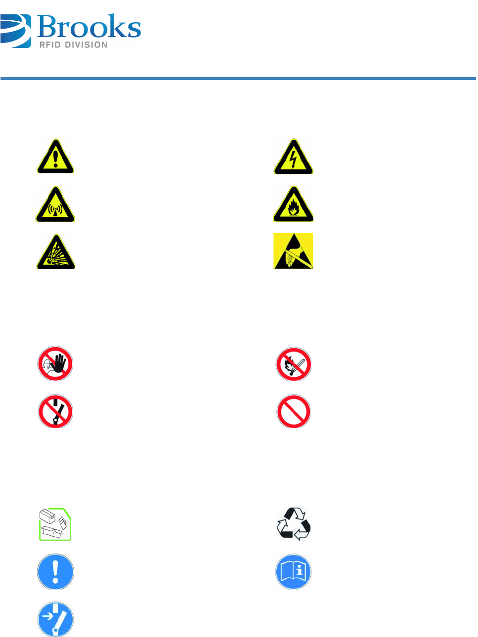
4.1.2 Warning symbols
4.1.3 Prohibition symbols
4.1.4 Other symbols
Warning against
hazardous area
Warning against
hazardous electrical
voltage
Warning against
electromagnetic
radiation
Warning against
flammable materials
Warning against
potentially explosive
atmosphere
Warning against
electrostatically
sensitive components
Unauthorized access
is prohibited
Fire, open flame and
smoking is prohibited
Switching is
prohibited
Prohibition
Dispose of packing
material according to
regulations
Recycling
Important
information
Refer to manual
Disconnect from
power supply
nbb

Product Manual - RFID Reader UF80 16
Chapter 4
Safety Instructions
4.2 Obligations
4.2.1 Operating company’s obligations
The safe condition and use of the device is a requirement for the safe operation of
the device. The company operating the device therefore has the obligation to
ensure that the following points are adhered to:
4.2.2 Operating personnel’s obligations
The operating personnel is obligated to contribute to the prevention of work
accidents and the consequences of them by their personal conduct.
The device may only be operated by trained and authorized personnel!
Avoid unsafe and/or dangerous work procedures! If necessary, check
employees' actions!
Only permit personnel to be trained or instructed or undergoing general
training to work on the device under the permanent supervision of an
experienced person!
Personnel must have understood the product manual. Have this confirmed
by signature!
Precisely establish responsibilities according to the various task areas
(operation, installation)!
Operating personnel must be committed to immediately reporting to their
superior any identifiable safety deficiencies which occur!
WARNING Risk of injuries due to insufficient personnel qualifications
A risk exists for personnel and the proper operation due to insufficiently
qualified personnel.
Only trained personnel may operate the device. New operators must be
instructed by the current operating personnel. The operating company must
precisely regulate and monitor the personnel's areas of responsibility and
competence.
Personnel for the areas of responsibility mentioned above must have the
corresponding qualification for this work (training, instructions). If necessary,
this can be done by the manufacturer on behalf of the operating company.
All warranty claims are void when disregarded.
Product Manual - RFID Reader UF80 17
Chapter 4
Safety Instructions
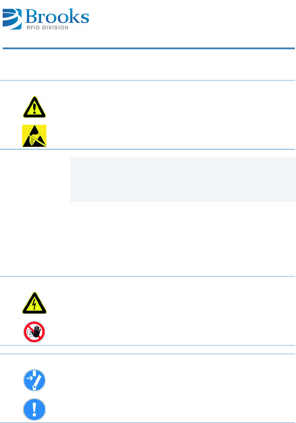
4.3 ESD instructions
4.4 Residual risks
Even if all precautions have been taken, there may be unapparent residual risks!
Adhering to the safety instructions, the intended use, and the product manual as
a whole can reduce residual risks!
CAUTION Static electricity can damage electronic components in the device. All persons
installing or maintaining the device must be trained in ESD protection.
ESD protective measures must be applied when opening the device.
Disconnect the power supply prior to removing or adding components!
Discharge your body and all tools used prior to contacting any components
on the interior of the device!
Touch electronically sensitive parts carefully and at the corners!
DANGER Risks from electric current
Electrical energy remains in lines, equipment and devices even when the device
is switched off.
Only allow qualified electricians to perform work on the electrical supply
system.
ATTENTION Disconnect the device from the power supply system if active parts of the
device can be accessed by using tools. Access is only permitted for authorized
personnel.
Regularly check the electrical equipment of the device. Regularly check all
moving cables for damage within the scope of maintenance and repairs.
Product Manual - RFID Reader UF80 18
Chapter 4
Safety Instructions
4.5 Additional information
■Read and understand all safety and operating instructions prior to
installing and operating the device.
■This documentation was written for specifically trained personnel.
Installation, operation and troubleshooting may only be carried out by
specifically trained personnel.
■Retain these instructions. Keep this documentation in a location that is
accessible to all personnel involved with the installation, use, and
troubleshooting of the device.
■Follow all warnings. Follow all warnings on and in the device and in the
documentation.
■Install the device only in accordance with the manufacturer's
instructions.
■Use only the accessories and cables from the manufacturer.
■Troubleshooting that is not described in Chapter Service and
Troubleshooting may only be performed by the manufacturer.
■People with hearing aids should be aware that the radio signals emitted
by the device can cause annoying noises in the hearing aid.
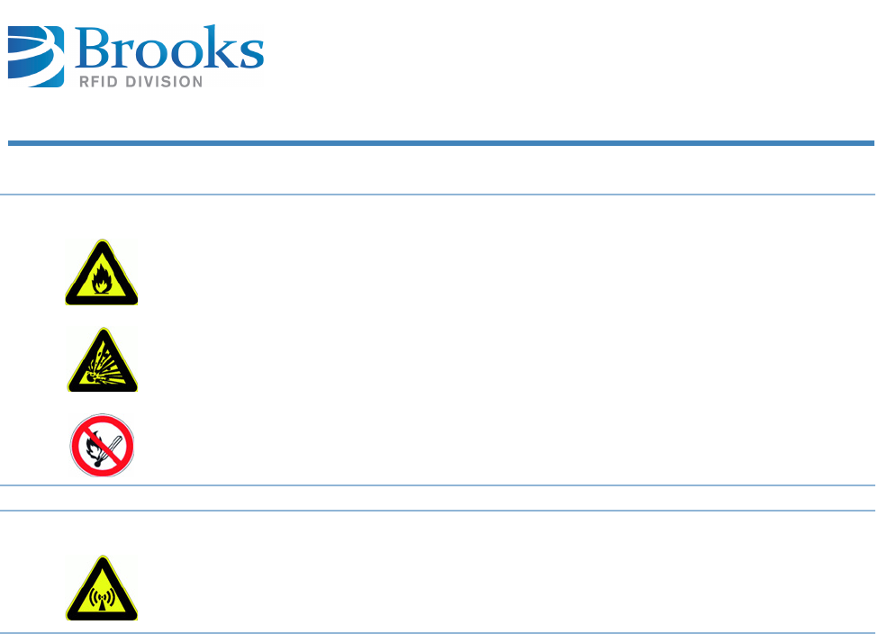
DANGER Risk of fire and explosions
Fire and explosions may occur within the vicinity of the device.
Smoking, open flames and fire are strictly prohibited in the vicinity of the
device. Do not store any flammable liquids within the hazardous area of the
device. Keep a fire extinguisher in the vicinity of the device.
WARNING Warning against electromagnetic radiation
Electromagnetic radiation develops when transmitting and receiving data.
Set the antenna in such a position that it is not in the vicinity of or touches a
human body while transmitting.

Product Manual - RFID Reader UF80 19
Chapter 4
Safety Instructions
■Do not connect the device to power supplies such as normal household
electrical outlets. The device should only be connected to power supplies
as specified in this document.
■When removing a cable, only pull on the plug and not on the cable.
Connect cable connectors straight and carefully to avoid damaging the
contacts.
■Never overbend the antenna cables or subject these to mechanical
forces.
■When replacement parts are required, use only the replacement parts
that were specified by the manufacturer. Unauthorized spare parts can
result in fire, electric shock or other hazards.
Rules and
regulations
The provisions of the accident prevention regulations of the government safety
organizations always apply to all work on the device.
The following must also be observed:
■applicable legally binding accident-prevention regulations
■applicable binding regulations at the place of use
■the recognized technical rules for safe and professional work
■existing environmental protection regulations
■other applicable regulations
Product Manual - RFID Reader UF80 20
Chapter 5
Product Specifications
5 Product Specifications
This chapter gives you an overview of the following topics:
■ Function
■ Images
■ Description of the components
■ Technical data
5.1 Function
The BROOKS RFID UF80 reader is a multiprotocol reader for reading passive
transponders in the frequency range of 865 MHz to 868 MHz for Europe and
902 MHz - 928 MHz for the FCC.
The device has a transmission output of between 7 and 26.5 dBm.
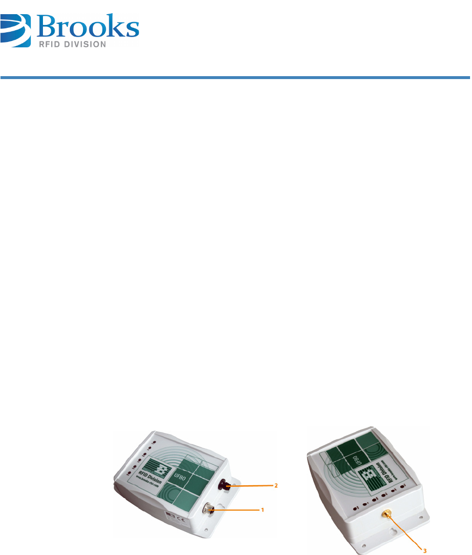
5.2 Images
5.2.1 Side view
1Ethernet interface
2Power (24 V)
3Antenna port (for external antenna)
Product Manual - RFID Reader UF80 21
Chapter 5
Product Specifications
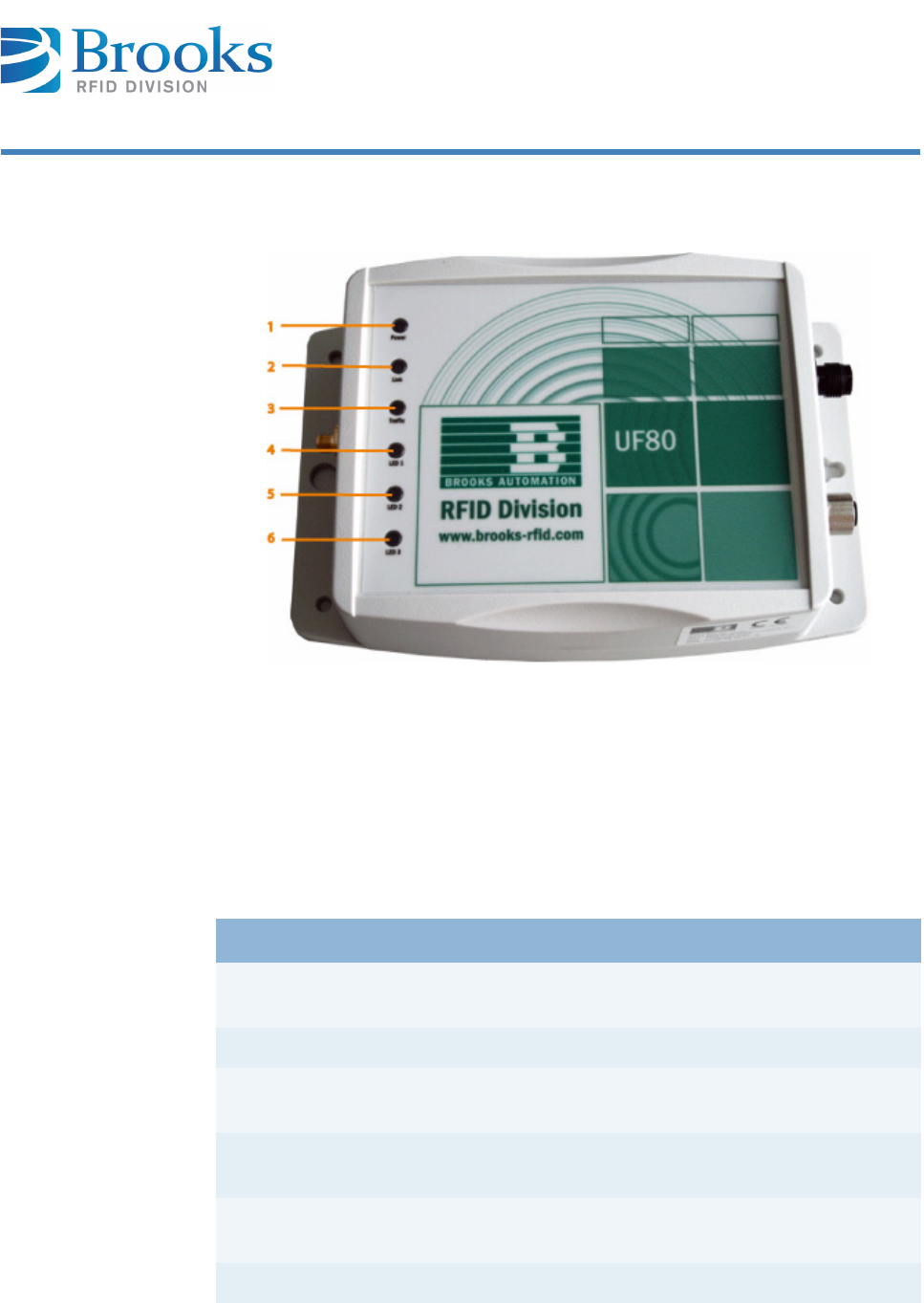
5.2.2 Top view
5.3 Description of the components
1Power LED 4LED 1 (red LED), configurable
2Link LED 5LED 2 (green LED), configurable
3Traffic LED 6LED 3 (yellow LED), configurable
Components Description
Power LED If the correct voltage is applied to the device, the
Power LED is green and the device is operational.
Link LED The link LED shows a TCP/IP connection.
Traffic LED The traffic LED flashes briefly when data are
transmitted or received.
Ethernet interface Communication with the device can be carried out
via the 10/100 BaseT interface.
Voltage supply
connection
Contact for connecting the 24 V DC voltage supply.
LED 1 - 3 LEDs can be set by the user via a command.
nbb

Product Manual - RFID Reader UF80 22
Chapter 5
Product Specifications
5.4 Technical data
Technical data
Voltage 24 V DC (20 - 30 V DC)
Power consumption approx. 0.2 A at 24 V
Ethernet interface 10/100 BaseT
Air interface ISO 18000-6C (EPCglobal Class 1
Gen2)
Frequency range Europe 865 - 868 MHz
Frequency range FCC 902 - 928 MHz
Transmitting power 7 - 26.5 dBm, parameterizable in
1dBm steps
Read/write range
(integrated antenna)
up to 0.8 m
Read/write range
(external antenna)
depending on the antenna
(typ. 2 m)
Antenna port (external antenna) SMA socket, impedance 50 ohm
Dimensions 190 x 126 x 54 mm
Weight approx. 400 g
Protection class IP 65
Housing material Polycarbonate
Operating temperature -20 °C to 50 °C
-4 °F to 122 °F
Storage temperature -40 °C to 85 °C
-40 °F to 185 °F
Permissible humidity at 50 °C / 122 °F 25% - 85%
Product Manual - RFID Reader UF80 23
Chapter 5
Product Specifications
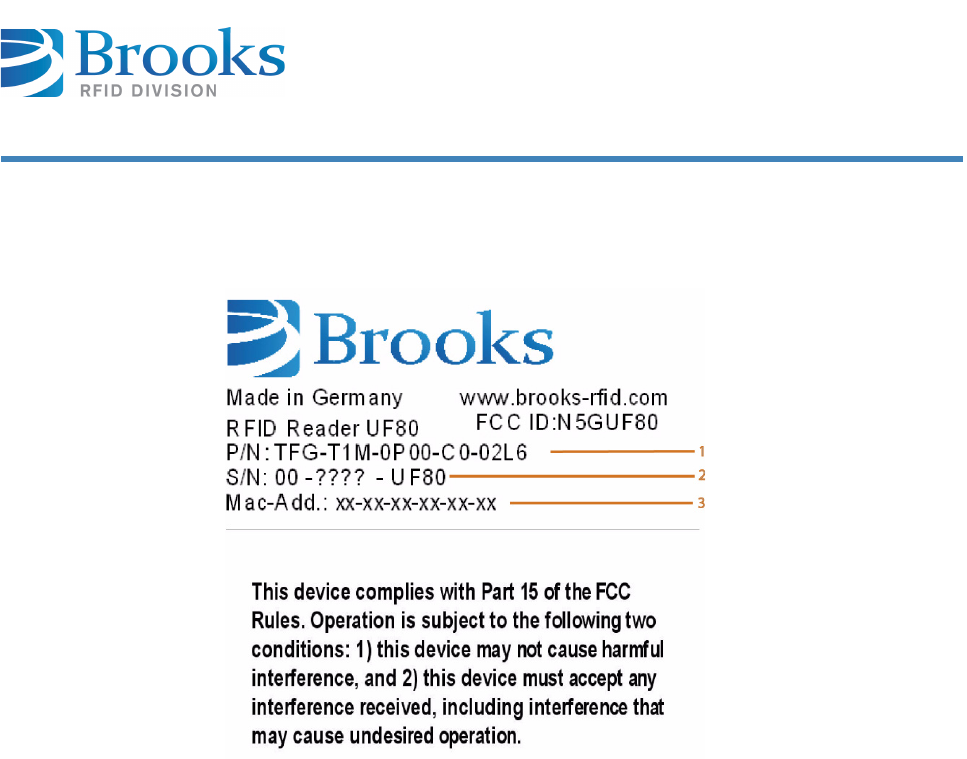
Device label The device label with the CE mark, part/serial number, and the MAC address is on
the device housing.
1Part number
2Serial number
3MAC address
Product Manual - RFID Reader UF80 24
Chapter 6
Installation
6 Installation
This chapter gives you an overview of the following topics:
■ Safety instructions
■ Qualified installation personnel
■ Unpacking
■ Assembly of the device
■ Antenna installation
■ Power supply
■ Ethernet interface 10/100 BaseT
■ Commissioning
6.1 Safety instructions
Refer to manual
Follow the general safety instructions in the chapter Safety Instructions.
CAUTION The device is exclusively designed for indoor use in an industrial environment.
Installation is only allowed in an interior room at a constant temperature
between -20 °C/-4 °F and +50 °C/122 °F, and a relative humidity between
25% and 80%.
Never use the device near or in water.
Never pour liquids of any type over the device. If the device should accidentally
come in contact with liquid, disconnect it and have it checked by a technician.
Do not install the device near heat sources such as radiators, heat registers,
stoves or other devices (including amplifiers) that generate heat.
Do not install the device in a flammable environment.
Product Manual - RFID Reader UF80 25
Chapter 6
Installation
CAUTION Never expose the device to extreme temperature fluctuations, since otherwise
condensation develops in the device, which can cause damage.
Do not install the device in the vicinity of voltage lines or other power lines with
which they could collide (for example, when drilling), which could result in
serious injuries or even death.
The device (especially the antenna) should not be installed in the immediate
vicinity of electrical equipment such as medical devices, monitors, telephones,
TV sets, magnetic disks and metal objects.
This could result in reduced read and write ranges.
Never use the device in explosive areas (e.g. paint warehouses).
CAUTION Do not use the device in areas where it is exposed to vibrations or shocks.
ATTENTION The installation location must be adequately illuminated during the installation.
Never install the device during a lightning storm.
Verify that the installation meets the requirements of the (country-specific)
FCC for human exposure to radio frequencies.
nbb
Product Manual - RFID Reader UF80 26
Chapter 6
Installation
6.2 Qualified installation personnel
6.3 Unpacking
The device and the accessories are packed under clean-room conditions. In order
to maintain this condition, the device must also be unpacked in clean-room
conditions.
Disposing of the
packaging material
ATTENTION When determining the installation site, keep in mind the length of the antenna
wire and the read/write range of the antenna used.
ATTENTION The antennas must be positioned at a distance of more than 10 cm from any
people in the vicinity.
CAUTION The installation is to be carried out by specially trained personnel only. If you
are uncertain about their qualification, contact the manufacturer.
CAUTION Operating the device without special training can result in damage to the
reader and/or connected devices.
The packaging material consists of cardboard and foil. Dispose of these
materials separately, and observing the legal regulations of your country.
Product Manual - RFID Reader UF80 27
Chapter 6
Installation
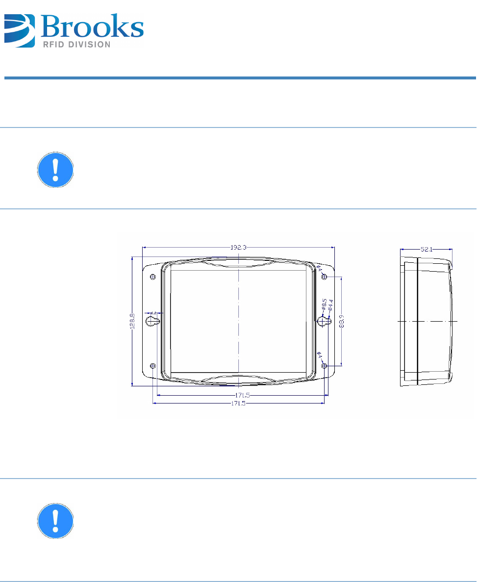
6.4 Assembly of the device
Installation
dimensions
6.5 Antenna installation
ATTENTION The mounting surface must be stable, non-flammable, dry and clean.
If necessary, clean it before you install the device.
The device must be installed in such a way that air can freely circulate, and the
operating and environmental conditions specified under Technical data are
met at all times.
ATTENTION Consider the read/write ranges required when installing the antenna. The
reader can only be used properly if the transponder is located within the
individual read/write range of the antenna.
If the transponder is very close to the antenna, the transponder may be de-
tuned by the metal of the antenna and a reading/writing is not possible. We
recommend keeping a minimum distance between transponder and antenna of
about 10 mm.
Product Manual - RFID Reader UF80 28
Chapter 6
Installation
6.5.1 Positioning the antenna
Reliable reading and writing depends on the distance from and orientation of the
transponder to the antenna.
Depending on the polarization of the antenna and the design of the transponder,
the orientation of the two should be considered when a reliable identification must
be guaranteed.
More information on application-specific antenna structures can be obtained from
our support team.
6.5.2 Available antenna types
Different types of antennas are available on request.
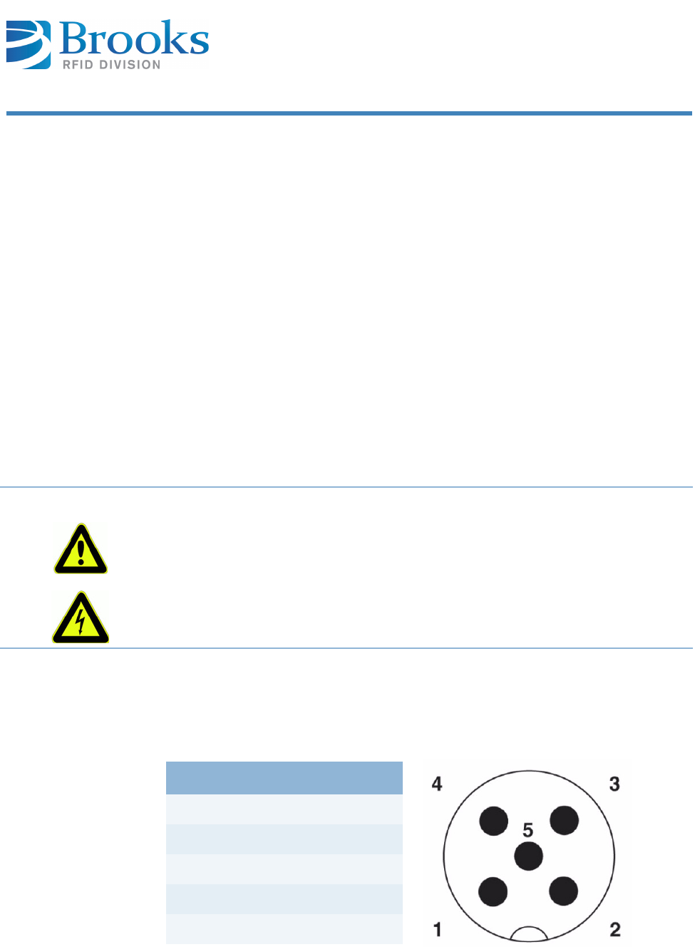
6.6 Power supply
Once the device is connected to the power supply, the power LED lights up.
If the LED does not light up, please refer to the chapter Error display with
LEDs.
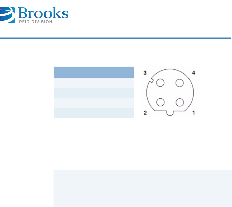
Pin assignment
power supply M12
plug
DANGER Risk of death from dangerous voltage
Risks exist when supplying the device with incorrect voltage.
Only use cables, plugs and adapters supplied by the manufacturer.
Observe the power ratings of the technical data ( Technical data).
Pin Signal
124 V DC+
224 V DC-
3NC
4NC
5NC
Product Manual - RFID Reader UF80 29
Chapter 6
Installation
6.7 Ethernet interface 10/100 BaseT
Pin assignment
Ethernet socket
M12
D coded
6.8 Commissioning
6.8.1 Required operating conditions
To operate the reader, the following requirements must be met:
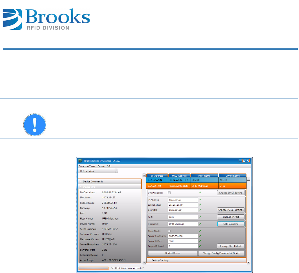
6.8.2 Brooks Device Discoverer
The 10/100 BaseT Ethernet interface has the following default settings:
DHCP mode OFF
IP address 10.73.254.211
Gateway address 10.73.254.254
Subnet mask 255.255.254.0
TCP/IP 3241
If DHCP is enabled and the DHCP Server is not available, the device initializes the
Ethernet connection with the following values:
IP address 169.254.MAC5.MAC6
Gateway 169.254.MAC5.254
Subnet mask 255.255.255.0
Primary DNS Server IP 0.0.0.0
Secondary DNS Server I 0.0.0.0
(MAC address MAC1:MAC2:MAC3:MAC4:MAC5:MAC6)
Pin Signal
1TX+
2RX+
3TX-
4RX-
An antenna must be connected correctly to the reader.
The power supply must be connected.
The transponder must be located within the individual read/write range of
the antenna.
Product Manual - RFID Reader UF80 30
Chapter 6
Installation
The Brooks Device Discoverer Tool can be used to find a device in the network
and to change the network settings easily. After sending a configuration message,
the tool requests the device configuration password. Please enter the default
passwort for Brooks RFID devices: BROOKS.
The tool can also be used to perform a firmware update.
For more information on the tool please refer to the manual of the Brooks Device
Discoverer
ATTENTION Using the UPx commands, the nework setting can also be changed via the host
interface.
Product Manual - RFID Reader UF80 31
Chapter 7
Operation
7Operation
This chapter gives you an overview of the following topics:
■ Operating personnel
■ Communication protocol ASC-I1
■ Additional information
7.1 Operating personnel
7.2 Communication protocol ASC-I1
7.2.1 Structure of the communication protocol
General remarks:
■The communication is done with ASCII packages.
■Each device has an Ethernet interface to which an address from 0 to E
can be assigned. When the reader is delivered, the address is 0.
■After each command to the reader, a defined response is sent. We
recommend waiting for this response before sending a new command.
7.2.2 Package contents
General remarks:
Each package includes a package header (three characters), a message (two or
more characters) and the end of the package (five characters).
CAUTION The UF80 RFID reader should only be operated by specially trained personnel.
If you have doubts about the required qualifications, contact the manufacturer.
Operating the device without special training can result in damage to the reader
and/or connected devices.
Package header Message End of package
Product Manual - RFID Reader UF80 32
Chapter 7
Operation
Package header The header includes the start character (one character) and the package length
(two characters).
The message length describes the number of characters of a message.
Message structure The message contains a command, a target or source address, the number of the
antenna port (Head - here always 1) and the actual information.
* The reader is preset with 0 when delivered.
End of package The end of the package includes an end character (1 character).
Package header
Start Length 1 Length 2
Start Start character (ASCII character 'S')
Length 1 High byte message length (hexadecimal) -
ASCII characters ´0´..´F´
Length 2 Low byte message length (hexadecimal) -
ASCII characters ´0´..´F´
Message
Command Address Head Information
Command ASCII characters (see section Commands of protocol)
Address Target/source address; ASCII characters '0'...'E' *
Head Optional - for messages that refer to a specific antenna
port
Information Depending on the command (contains none, one or more
ASCII characters '0'...'F')
End of package
End
End End character ASCII character number 13 (hexadecimal 0D)
ATTENTION The end of the message does not contain a checksum, because communication
is exclusively carried out via TCP/IP.
nbb

Product Manual - RFID Reader UF80 33
Chapter 7
Operation
7.2.3 Commands of protocol
Commands
Command Description
URY URY - Read data range (defined EPC code)
M M - Scan EPCs
W W - Write EPC code
UWZ UWZ - Write data range of all EPC transponders (defined
EPC code)
ULZ ULZ – Locking all EPC transponders (defined EPC code)
F F - Query parameters
P P - Set parameter
O O - Set output
E E - Error message
H H - Heartbeat
V V - Query software version
K K - Polling
UFD UFD - Query DHCP Enabled
UPD UPD - Set DHCP Enabled
UFI UFI - Query network settings
UPI UPI - Set network settings
UFN UFN - Query host name
UPN UPN - Set host name
Product Manual - RFID Reader UF80 34
Chapter 7
Operation
Message items
The 4-byte access word is required to access the various memory areas of the
EPC transponder. The LSB byte is always transmitted first during the
transmission. The data are interpreted in HEX format. This means that two ASCII
characters in the message equal one byte of data in HEX format.
Example:
0x01020304
ASCII string "04030201"
Data words (2 bytes) are always read or written. The data are interpreted in HEX
format. This means that two ASCII characters in the message describe one byte
of transponder data in HEX format.
Example:
HEX transponder data 0x12, 0x34, 0x56, 0x78 (2 data words)
ASCII transmission 0x31, 0x32, 0x33, 0x34, 0x35, 0x36, 0x37, 0x38
Transmitted ASCII string "12345678"
A network configuration that determines if the static network address is being
used or if the DHCP server assigns the network address.
"0" DHCP is not active; use static network address
"1" DHCP is active; obtain network address from the DHCP server
Access word 8 bytes
Data words 2 to N*4 bytes
DHCP 1 byte

Product Manual - RFID Reader UF80 35
Chapter 7
Operation
For future developments, the EPC code should have a flexible length n from 0 to
31 data words (2 bytes data). The underlying software version UF80V1.1 still
uses a fixed EPC length of 6 data words. An n byte is placed before the actual EPC
code and corresponds to the quantity of EPC data words. The EPC code is
transferred in such a way that the LSB byte is transmitted first. The data are
interpreted in HEX format. This means that two ASCII characters in the message
equal one byte of data in HEX format. The following applies to the number of EPC
data words n: 0<=n<=31
Example:
ASCII string "060C0B0A090807060504030201"
-> Number n of EPC data words 0x06
-> EPC 0x0102030405060708090A0B0C
The extension flag determines which information is included in the recognized
EPC transponder. The Ex flag is set by parameter 0x76. The data are interpreted
in HEX format. This means that two ASCII characters in the message equal one
byte of data in HEX format.
Values:
0x00 do not transmit extensions
0x01 only transmit antenna port
0x02 only transmit RSSI value
0x03 transmit antenna port and RSSI
0x04 transmit time stamp
0x05 transmit time stamp and antenna port
0x06 transmit time stamp and RSSI value
0x07 transmit time stamp, RSSI value and antenna port
0x08 transmit transponder protocol control word
0x09 transmit antenna port and transponder protocol control word
0x0A transmit RSSI value and protocol control word
0x0B transmit antenna port, RSSI value and protocol control word
0x0C transmit time stamp and protocol control word
0x0D transmit time stamp, antenna port and protocol control word
0x0E transmit time stamp, RSSI value and protocol control word
0x0F transmit time stamp, antenna port, RSSI value and protocol control word
EPC (2n+1)*2
bytes
Ex flag 2 bytes

Product Manual - RFID Reader UF80 36
Chapter 7
Operation
If and which extensions are transmitted for each detected EPC transponder is
defined by the Ex flag. The data are interpreted in HEX format. This means that
two ASCII characters in the message equal one byte of data in HEX format. The
activated extensions are transferred in the following order:
2 ASCII characters antenna port
2 ASCII characters RSSI value
8 ASCII characters time stamp (number of ms that have passed since
the start of the reader, the LSB byte is transferred
first)
4 ASCII characters protocol word PC of the transponder
The response of the reader can be accomplished in several frames (e.g. if many
transponders were scanned). The frame ID that is sent indicates how many
response messages follow. Short responses that consist only of a single frame
then always have the frame ID "00". Messages consisting of multiple frames
should be fully received and assembled by the host before they are processed.
The data are interpreted in HEX format. This means that two ASCII characters in
the message equal one byte of data in HEX format.
Gateway address of the network setting with a size of 4 bytes.
The data are in HEX format. This means that two ASCII characters in the message
equal one byte of data in HEX format.
Example:
Subnet address 255.255.254.0
0xFF 0xFF 0xFE 0x00
ASCII string "FFFFFE00"
Number of the antenna port (always 1 for this device). The Head ID is part of the
protocol, because it is also used for other devices with several antenna ports.
Extensions 0 to 12 bytes
Frame ID 2 bytes
GW-ADR 8 bytes
Head ID 1 byte

Product Manual - RFID Reader UF80 37
Chapter 7
Operation
Host name with a length of 1 to 15 bytes, whose hexadecimal interpretation is
transferred. The individual characters are interpreted in HEX format. This means
that two ASCII characters in the message equal one byte of data in HEX format.
Example:
Host name "UF80_10"
0x55 0x46 0x38 0x30 0x5F 0x31 0x30
ASCII string "554638305F3130"
IP address of the network setting with a size of 4 bytes.
The data are in HEX format. This means that two ASCII characters in the message
equal one byte of data in HEX format.
Example:
IP address 10.73.254.56
0x0A 0x49 0xFE 0x38
ASCII string "0A49FE38"
Defines the length of the data to be read or written. The two ASCII characters (2
bytes) specify the length of the data in HEX format.
Example:
Length 1 byte 0x01 "01"
Length 16 bytes 0x10 "10"
Length 25 bytes 0x19 "19"
Length 100 bytes 0x64 "64" (maximum length)
Host name 2 - 30 bytes
IP-ADR 8 bytes
Length 2 bytes
Product Manual - RFID Reader UF80 38
Chapter 7
Operation
A list of EPCs scanned by the reader. The list is represented by a character string.
Every EPC has a length of 12 bytes. In this character string, every byte of the EPC
is represented by 2 ASCII characters. This means that a complete EPC (12 bytes)
is represented by 24 ASCII characters.
The first 2 characters of a character string specify the number of EPCs in the
character string. These two characters describe a byte value in HEX format ("02"
means 0x02).
Example: List with 2 EPCs
02E0070000014CB96677889900E0070000014CB96777889900
EPC 1: 0xE0070000014CB96677889900
EPC 2: 0xE0070000014CB96777889900
The memory areas of the EPC transponder are addressed by 4 byte word
pointers. The LSB byte is always transmitted first during the transmission. The
data are interpreted in HEX format. This means that two ASCII characters in the
message equal one byte of data in HEX format. The exact memory structure can
be derived from the EPCglobal standard.
The EPC transponder has multiple memory banks, which are addressed by
number. The exact memory structure can be derived from the EPCglobal
standard. The data are interpreted in HEX format. This means that two ASCII
characters in the message equal one byte of data in HEX format.
Values:
"00" (0x00) Reserved
"01" (0x01) EPC
"02" (0x02) TID
"03" (0x03) User
List of EPCs 1 - 120 bytes
Memory address 8 bytes
Memory bank 2 bytes

Product Manual - RFID Reader UF80 39
Chapter 7
Operation
The number of data words (1 data word consists of 2 bytes) which are read/
written is hereby defined.
The data are in HEX format. This means that two ASCII characters in the message
equal one byte of data in HEX format.
Displays or sets the current status of the outputs. One byte is designated for each
output. The status of the outputs is transferred in the order IO a, IO b, IO c and
IO d as the last one.
Example:
0 - Output OFF
1 - Output ON
2 - Output flashes
3 - Output keeps the current status
LED 1 -> red LED
LED 2 -> green LED
LED 3 -> yellow LED
Number of the parameter. Two ASCII characters (2 bytes) display the parameter
number in HEX format.
Example:
Parameter 20 0x14 "14"
Value of the parameter. Two ASCII characters (2 bytes) specify the value of the
parameter in HEX format.
Example:
Parameter 192 0xC0 "C0"
Number of data words 2 bytes
Output state 4 bytes
Parameter no. 2 bytes
Parameter value 2 bytes

Product Manual - RFID Reader UF80 40
Chapter 7
Operation
Address of the device ("0" .. "E").
The default address of the card is 0 on delivery.
Brooks recommends leaving the reader ID at "0", since the device can be clearly
identified via its IP connection.
This feature is not used for the individual reader. This code is always "0000".
The result flag delivers information on whether an action was completed
successfully. The data are interpreted in HEX format. This means that two ASCII
characters in the message equal one byte of data in HEX format.
Values:
0x00 no errors occurred
0x0A no transponder was found
0x0B several transponder were found
0x70 transponder could not be selected during the transponder
operation
0x71 structure of W command not in line with specifications
Contains the 4-byte serial number of the device.
The serial number is also shown on the label of the reader.
Reader ID 1 byte
Response code 4 bytes
Result 2 bytes
IMPORTANT For writing operations to the transponder, the transponder error code must also
be analyzed to be able to make an assessment as to whether the action was
competed successfully.
Serial number 4 bytes
Product Manual - RFID Reader UF80 41
Chapter 7
Operation
Character string with the software version of the reader. The display is in HEX
format. This means that the 12 - 16 characters of the ASCII character string
describe the 6 - 10 bytes of the software version in HEX format.
Example:
v05546383056312E31
0x55 0x46 0x38 0x30 0x56 0x31 0x2E 0x30 = UF80V1.1
Subnet address of the network setting with a size of 4 bytes.
The data are in HEX format. This means that two ASCII characters in the message
equal one byte of data in HEX format.
Example:
Subnet address 255.255.254.0
0xFF 0xFF 0xFE 0x00
ASCII string "FFFFFE00"
The transponder itself also delivers an error code, which is also transmitted. The
data are interpreted in HEX format. This means that two ASCII characters in the
message equal one byte of data in HEX format.
Values:
0x00 No errors occurred.
0x83 The specified memory location does not exist or the EPC-
length field is not supported by the transponder.
0x84 The specified memory location is locked and/or permalocked
and is either not writeable or not readable.
0x8B The transponder has insufficient power to perform the
memory-write operation.
0x8F The transponder does not support error-specific codes.
Software version 6 - 10 bytes
SUB-ADR 8 bytes
Transponder error code 2 bytes

Product Manual - RFID Reader UF80 42
Chapter 7
Operation
URY - Read data
range (defined EPC
code)
The URY command starts the reading of a defined data range of the current EPC
transponders which have a defined EPC code. Several EPC transponders can be
located in the reading area of the antenna when using this command.
1) These data are displayed in the order listed for each identified EPC
transponder.
2) The response of the transponder is optional and only appears at result "00".
3) The result and Ex flag is only available in the first transmitted message in
messages with several frames.
Example: Read access password
>> URY01060102030405060708090A0BCD00000000000200000002
<< ury000000101060102030405060708090A0BCD000200000000
Host reader
CMD Reader
ID
Head
ID EPC Access
word
Memory
bank
Memory
address
Number of
data words
URY 1 byte 1 byte (2n+1)*2
bytes
8 bytes 2 bytes 8 bytes 2 bytes
Reader host
Overhead response telegram 2) Data of the participating EPC transponders 1) 2)
CMD Reader
ID
Frame
ID
Result
3)
Ex flag
3)
Exten-
sions EPC
Trans-
ponder
error
code
Number
N data
words
Data
words
ury 1 byte 2 bytes 2 bytes 2 bytes 0-12
bytes
(2n+1)
*2
bytes
2 bytes 2 bytes N*4
bytes

Product Manual - RFID Reader UF80 43
Chapter 7
Operation
M - Scan EPCs The M command starts the scanning of the EPC transponders located in the read
area of the activated antenna.
1) These data are displayed in the order listed for each identified EPC
transponder.
2) The response of the transponder is optional and only appears at result "00".
3) The result and Ex flag is only available in the first transmitted message in
messages with several frames.
Example:
>> M01
<< m0010001 Frame ID "01"; Result "00" and Ex flag "01"
0106470000000000000000000000
0106270000000000000000000000
0106110000000000000000000000
0106490000000000000000000000
0106100000000000000000000000
0106230000000000000000000000
0106420000000000000000000000
0106080000000000000000000000
0106310000000000000000000000
0106290000000000000000000000
0106120000000000000000000000
0106
the missing 12 bytes are included in the next message
Host reader
CMD Reader ID Head ID
M 1 byte 1 byte
Reader host
Overhead response telegram 2) Data of the participating EPC transponders 1) 2)
CMD Reader
ID
Frame
ID
Result
3)
Ex flag
3)
Exten-
sions EPC
Trans-
ponder
error
code
Number
N data
words
Data
words
m 1 byte 2 bytes 2 bytes 2 bytes 0-12
bytes
(2n+1)
*2
bytes
2 bytes 2 bytes N*4
bytes

Product Manual - RFID Reader UF80 44
Chapter 7
Operation
<<m000
250000000000000000000000
0106480000000000000000000000
0106410000000000000000000000
0106380000000000000000000000
0106280000000000000000000000
0106030000000000000000000000
0106170000000000000000000000
0106190000000000000000000000
0106400000000000000000000000
0106050000000000000000000000
0106090000000000000000000000
0106010000000000000000000000
0106240000000000000000000000
0106460000000000000000000000
0106260000000000000000000000
0106180000000000000000000000
0106390000000000000000000000
0106060000000000000000000000
>> M01
<< m0000A Result 0x0A, since no transponder is available
>> URM01
<< urm0000A Result 0x0A, since no transponder is available
>> URM01
<< urm0000001 Frame ID "00"; Result "00" and Ex flag "01"
01060B0C090A0708050603040102

Product Manual - RFID Reader UF80 45
Chapter 7
Operation
W - Write EPC code The W command starts the writing of the EPC of a present EPC transponder. Only
one EPC transponder may be located in the write area of the antenna when using
this command.
1) The transponder here delivers the EPC code which was previously programmed
as a response.
2) The response of the transponder is optional and only appears at result "00".
Example: Overwrite EPC transponder with a new EPC code
>> M01 (read old EPC code)
<< m000000101060102030405060708090A0BCD
>> W0100000000060102030405060708090A0B0C
<< w000000101060102030405060708090A0BCD8B
>> M01 (read new EPC code)
<< m000000101060102030405060708090A0B0C
Example: Several transponders are in the field; the action is therefore incorrect
>> W0100000000060102030405060708090A0B0C
<< w0000B Result 0x0B
Host reader
CMD Reader ID Head ID Access word EPC
W 1 byte 1 byte 8 bytes (2n+1)*2 bytes
Reader host
Overhead response telegram Response of the EPC transponder 2)
CMD Reader
ID
Frame
ID Result Ex flag Extensions EPC 1) Transponder
error code
w 1 byte 2 bytes 2 bytes 2 bytes 0-12 bytes (2n+1)*2 bytes 2 bytes

Product Manual - RFID Reader UF80 46
Chapter 7
Operation
UWZ - Write data
range of all EPC
transponders
(defined EPC code)
The UWZ command starts to overwrite the defined data range of all EPC
transponders located in the field that have a defined EPC code. Several EPC
transponders can be located in the write area of the antenna when using this
command.
1) These data are displayed in the order listed for each identified EPC
transponder.
2) The response of the transponder is optional and only appears at result "00".
3) The result and Ex flag is only available in the first transmitted message in
messages with several frames.
Example: Overwrite several EPC transponders having the same EPC code with a
new EPC code
>> UWZ01060B0C090A07080506030401020000000001020000000601020304
05060708090A0B0C
<< uwz000000101060B0C090A070805060304010200
Control reading:
>> M01
<< m0000001
01060B0C090A0708050603040102
EPC: 02010403060508070A090C0B
>> M01
<< m0000001
01060102030405060708090A0B0C
01060102030405060708090A0B0C
01060102030405060708090A0B0C
Host reader
CMD Reader
ID
Head
ID EPC Access
word
Memory
bank
Memory
address
Number N
data
words
Data
words
UWZ 1 byte 1 byte (2n+1)*2
bytes
8 bytes 2 bytes 8 bytes 2 bytes N*4 bytes
Reader host
Overhead response telegram 2) Data of the participating EPC transponders 1) 2)
CMD Reader
ID
Frame
ID Result 3) Ex
flag 3) Extensions EPC 1) Transponder
error code
uwz 1 byte 2 bytes 2 bytes 2 bytes 0-12 bytes (2n+1)*2
bytes
2 bytes

Product Manual - RFID Reader UF80 47
Chapter 7
Operation
EPC: 0C0B0A090807060504030201
EPC: 0C0B0A090807060504030201
EPC: 0C0B0A090807060504030201
>> UWZ01060102030405060708090A0B0C000000000102000000061122334
45566778899AABBCC
<< uwz000000101060102030405060708090A0B0C00
>> M01
<< m0000001
0106BBCC99AA7788556633441122
01060102030405060708090A0B0C
01060102030405060708090A0B0C
>> UWZ01060102030405060708090A0B0C00000000010200000006112233
445566778899AABBCC
<< uwz000000101060102030405060708090A0B0C00
>> UWZ01060102030405060708090A0B0C0000000001020000000611223344
5566778899AABBCC
<< uwz000000101060102030405060708090A0B0C00
>> UWZ01060102030405060708090A0B0C00000000010200000006112233
445566778899AABBCC
<< uwz0000A
>> M01
<< m0000001
0106BBCC99AA7788556633441122
0106BBCC99AA7788556633441122
0106BBCC99AA7788556633441122
EPC: 2211443366558877AA99CCBB
EPC: 2211443366558877AA99CCBB
EPC: 2211443366558877AA99CCBB

Product Manual - RFID Reader UF80 48
Chapter 7
Operation
ULZ – Locking all
EPC transponders
(defined EPC code)
The ULZ command starts to lock all EPC transponders with the corresponding EPC
code located in the field. Several EPC transponders can be located in the write
area of the antenna when using this command.
1) These data are displayed in the order listed for each identified EPC
transponder.
2) The response of the transponder is optional and only appears at result "00".
3) The result and Ex flag is only available in the first transmitted message in
messages with several frames.
Example: Lock the Kill block of an EPC transponder
>> M01
<< m00000010106670488EC41381FAC63FB0530
>> UWZ0106670488EC41381FAC63FB053000000000000000000004FEFEFEFE
FEFEFEFE
<< uwz00000010106670488EC41381FAC63FB053000
Kill password and access word written
Payload 0x0C0300; Permalock=1
>> ULZ0106670488EC41381FAC63FB0530FEFEFEFE00030C
<< ulz00000010106010203040500683D4A960D3000
Since Permalock was set, the Kill password cannot be read or written after the
locking process!
>> UWZ0106670488EC41381FAC63FB053000000000000000000002FEFEFEFE
<< uwz00000010106010203040500683D4A960D3084
Kill password can no longer be written!
Host reader
CMD Reader ID Head ID EPC Access word Payload
ULZ 1 byte 1 byte (2n+1)*2 bytes 8 bytes 6 bytes
Reader host
Overhead response telegram 2) Data of the participating EPC transponders 1) 2)
CMD Reader
ID
Frame
ID Result 3) Ex flag
3) Extensions EPC Transponder
error code
ulz 1 byte 2 bytes 2 bytes 2 bytes 0-12 bytes (2n+1)*2
bytes
2 bytes
Product Manual - RFID Reader UF80 49
Chapter 7
Operation
F - Query
parameters
The F command is used to query individual parameters ( Parameter) of the
device. The number of the parameter is transmitted in "Parameter No.". The
response contains the parameter number and value. The parameter number and
the value are specified in HEX format, for example Parameter 11 (0x0B).
1) If no parameter number is specified, the reader will provide all reader
parameters. A single response telegram is then sent for each parameter. The
parameter value can be multi-digit (N>=1)!
Example:
15.09.2011 09:44:31 Info: Send Message: F062
15.09.2011 09:44:31 Info: Message Stream Sent: 53 30 34 46 30 36 32 0D
15.09.2011 09:44:31 Info: Message Stream Received: 53 30 36 66 30 36 32 33
36 0D
15.09.2011 09:44:31 Info: Received Message: f06236
Query of the temperature of the processor value 0x36 equals 54 °C
Host reader
CMD Reader ID Parameter no. 1)
F 1 byte 2 bytes
Reader host
CMD Reader ID Parameter no. Parameter value
f 1 byte 2 bytes N*2 bytes
Product Manual - RFID Reader UF80 50
Chapter 7
Operation
P - Set parameter The P command sets the individual parameter values ( Parameter) of the
device. After successfully setting a parameter, the device sends a confirmation or
carries out a reset (depending on the parameter).
Example:
Reader 0; Parameter 04; Value 0x32 (50 dec.)
>> p00432
<< p0
IMPORTANT After setting one or several parameters, a reset is to be carried out as some
parameters affect hardware settings.
Host reader
CMD Reader ID Parameter no. Parameter value
P 1 byte 2 bytes N*2 bytes
Reader host
CMD Reader ID
p1 byte
Product Manual - RFID Reader UF80 51
Chapter 7
Operation
N - Reset The N command performs a reset of the reader hardware. After the reset, the
Ethernet connection to the device has to be reestablished.
Example:
Set output:
18.08.2011 12:56:02 Info: Send Message: N0
18.08.2011 12:56:02 Info: Message Stream Sent: 53 30 32 4E 30 0D
18.08.2011 12:56:17 Info: Reader Response Timeout - No communication with
RFID reader!
after a reset, all outputs are off
IMPORTANT After setting one or several parameters, a reset is to be carried out as some
parameters affect hardware settings.
Host reader
CMD Reader ID
N1 byte

Product Manual - RFID Reader UF80 52
Chapter 7
Operation
O - Set output The O command changes the status of the corresponding output. To keep the
current status of an output, use value 3 - keep status.
The outputs can always be set, irrespective of whether the corresponding I/O has
been configured as input or output.
Output state:
LED 1 -> red LED
LED 2 -> green LED
LED 3 -> yellow LED
Example:
18.08.2011 12:56:20 Info: Send Message: O013333
18.08.2011 12:56:20 Info: Message Stream Sent: 53 30 37 4F 30 31 33 33 33
33 0D
18.08.2011 12:56:20 Info: Message Stream Received: 53 30 33 6F 30 31 0D
18.08.2011 12:56:20 Info: Received Message: o01
everything remains off and unchanged
18.08.2011 12:56:38 Info: Send Message: O010123
18.08.2011 12:56:38 Info: Message Stream Sent: 53 30 37 4F 30 31 30 31 32
33 0D
18.08.2011 12:56:38 Info: Message Stream Received: 53 30 33 6F 30 31 0D
18.08.2011 12:56:38 Info: Received Message: o01
Buzzer off, green LED on, yellow LED flashes, red LED remains off
Host reader
CMD Reader ID Head ID
Output state
Buzzer Green LED Yellow
LED Red LED
O 1 byte 1 byte 1 byte 1 byte 1 byte 1 byte
Reader host
CMD Reader ID Head ID
o 1 byte 1 byte

Product Manual - RFID Reader UF80 53
Chapter 7
Operation
18.08.2011 12:56:56 Info: Send Message: O011331
18.08.2011 12:56:56 Info: Message Stream Sent: 53 30 37 4F 30 31 31 33 33
31 0D
18.08.2011 12:56:56 Info: Message Stream Received: 53 30 33 6F 30 31 0D
18.08.2011 12:56:56 Info: Received Message: o01
Buzzer on, green LED remains on, yellow LED keeps flashing, red LED on
18.08.2011 12:57:17 Info: Send Message: O010111
18.08.2011 12:57:17 Info: Message Stream Sent: 53 30 37 4F 30 31 30 31 31
31 0D
18.08.2011 12:57:17 Info: Message Stream Received: 53 30 33 6F 30 31 0D
18.08.2011 12:57:17 Info: Received Message: o01
Buzzer off, all LEDs on
Product Manual - RFID Reader UF80 54
Chapter 7
Operation
E - Error message If an error occurs, the device sends an error message with a corresponding error
code.
This message must be confirmed by the host (depending on device setting
parameter 12).
For more information on error codes and the corresponding correcting actions
please refer to Error codes.
Reader host
CMD Reader ID Error ID
E 1 byte 1 byte
Host reader
CMD Reader ID
e1 byte

Product Manual - RFID Reader UF80 55
Chapter 7
Operation
H - Heartbeat The H command can be used to query the serial number of the device.
The response code is not required for the individual device. This code is always
"0000".
Example:
15.09.2011 09:47:31 Info: Send Message: H0
15.09.2011 09:47:31 Info: Message Stream Sent: 53 30 32 48 30 0D
15.09.2011 09:47:31 Info: Message Stream Received: 53 30 41 68 30 31 32 33
34 30 30 30 30 0D
15.09.2011 09:47:31 Info: Received Message: h012340000
Host reader
CMD Reader ID
H1 byte
Reader host
CMD Reader ID Serial number Response code
h 1 byte 4 bytes 4 bytes
Product Manual - RFID Reader UF80 56
Chapter 7
Operation
V - Query software
version
The V command queries the software version of the device.
The 8 characters for the software version are described by 16 ASCII characters.
Each of the 8 characters is shown in HEX format, represented by 2 ASCII
characters.
Example:
15.09.2011 09:48:54 Info: Send Message: V0
15.09.2011 09:48:54 Info: Message Stream Sent: 53 30 32 56 30 0D
15.09.2011 09:48:55 Info: Message Stream Received: 53 31 32 76 30 35 35 34
36 33 38 33 30 35 36 33 31 32 45 33 31 0D
15.09.2011 09:48:55 Info: Received Message: v05546383056312E31
Version "UF80V1.1"
Host reader
CMD Reader ID
V1 byte
Reader host
CMD Reader ID Software version
v 1 byte 16 bytes
Product Manual - RFID Reader UF80 57
Chapter 7
Operation
K - Polling If the reader is in polling mode, the surrounding area of the antenna is scanned
for transponders (inventory). Each of the EPCs of the detected transponders are
sent to the host in an individual K message. The device can process up to 9 EPCs
at the same time.
Example:
>> K0101CCBBAA998877665544332211
<< k01
Reader host
CMD Reader ID Head ID List of EPCs
K 1 byte 1 byte 1 - 120 bytes
Host reader
CMD Reader ID Head ID
k 1 byte 1 byte

Product Manual - RFID Reader UF80 58
Chapter 7
Operation
UFD - Query DHCP
Enabled
This command queries the network setting "DHCP Enabled".
Example:
>> UFD0
<< ufd00
DHCP: "0" DHCP is not activated
Default value: "1" DHCP enabled
Host reader
CMD Reader ID
UFD 1 byte
Reader host
CMD Reader ID DHCP
ufd 1 byte 1 byte
Product Manual - RFID Reader UF80 59
Chapter 7
Operation
UPD - Set DHCP
Enabled
This command sets the network setting "DHCP Enabled".
Example: activate DHCP
>> UPD01
<< upd0
Example: deactivate DHCP
>> UPD00
<< upd0
Host reader
CMD Reader ID DHCP
UPD 1 byte 1 byte
Reader host
CMD Reader ID
upd 1 byte
Product Manual - RFID Reader UF80 60
Chapter 7
Operation
UFI - Query
network settings
This command queries the network settings (IP, subnet and gateway address).
Example:
>> UFI0
<< ufi00A49FE4EFFFFFE000A49FEFE
IP 0A49FE4E
Sub FFFFFE0
GW 0A49FEFE
IP address "0A49FE4E" corresponds to 10.73.254.78
Subnet address "FFFFFE00" corresponds to 255.255.254.0
Gateway address "0A49FEFE" corresponds to 10.73.254.254
Host reader
CMD Reader ID
UFI 1 byte
Reader host
CMD Reader ID IP-ADR SUB-ADR GW-ADR
ufi 1 byte 8 bytes 8 bytes 8 bytes
Product Manual - RFID Reader UF80 61
Chapter 7
Operation
UPI - Set network
settings
This command sets the network settings (IP, subnet and gateway address).
Example:
IP 0A49FE4E
Sub FFFFFE0
GW 0A49FEFE
>> UPI00A49FE4EFFFFFE000A49FEFE
<< upi0
Host reader
CMD Reader ID IP-ADR SUB-ADR GW-ADR
UPI 1 byte 8 bytes 8 bytes 8 bytes
Reader host
CMD Reader ID
upi 1 byte
Product Manual - RFID Reader UF80 62
Chapter 7
Operation
UFN - Query host
name
This command queries the network setting "Host name". With the host name, the
reader receives an identifier and can therefore be identified in the network more
easily.
Example:
>> UFN0
<< ufn055463830
Host name "55463830" corresponds to "UF80"
Host reader
CMD Reader ID
UFN 1 byte
Reader host
CMD Reader ID Host name
ufn 1 byte 2 - 30 bytes
Product Manual - RFID Reader UF80 63
Chapter 7
Operation
UPN - Set host
name
This command sets the network setting "Host name". With the host name, the
reader receives an identifier and can therefore be identified in the network more
easily.
Example:
>> UPN0554638305F31
<< upn0
Host reader
CMD Reader ID Host name
UPN 1 byte 2 - 30 bytes
Reader host
CMD Reader ID
upn 1 byte

Product Manual - RFID Reader UF80 64
Chapter 7
Operation
7.2.4 Parameter
No.
(dec.)
No.
(hex) Parameter name
40x04 Delay time
60x06 MaxRepeat
11 0x0B Reader ID
12 0x0C Acknowledgment error message
16 0x10 Attenuation of transmission output
39 0x27 Polling frequency
43 0x2B Polling fallout
47 0x2F Polling mode
48 0x30 Buzzer delay
50 0x32 Buzzer volume
64 0x40 Support configuration transponder
65 0x41 Result code start procedure (read only)
66 0x42 MaxRepeat scan configuration transponder
98 0x62 Query temperature of the processor (read only)
99 0x63 Default parameter
118 0x76 Extended result flag
123 0x7B Fine version (read only)
158 0x9E Tag comm initial Q
162 0xA2 UHF asic parameter Tx driver current (register 0x0B)
163 0xA3 UHF asic parameter Rx gain
176 0xB0 TCP keep alive

Product Manual - RFID Reader UF80 65
Chapter 7
Operation
Parameter 4
(0x04)
Delay time
If a confirmation is not sent by the host, the device waits this time span before it
sends the message to the host again. The number of repetitions is defined in
parameter 6 (MaxRepeat).
0x0A - 0xFA (0.1 s) 1 - 25 s
Default: 0x32
Parameter 6
(0x06)
MaxRepeat
If a confirmation is not sent by the host, the device repeats the message
according to the set value. Only then is an error message sent.
0x00 - 0x1F
Default: 0x03
Parameter 11
(0x0B)
Reader ID
This parameter defines the address of the device in the ASC-I1 protocol. We
recommend keeping the default setting since the module can be identified via the
hardware interface.
0x00 - 0x0E
Default: 0x00
Parameter 12
(0x0C)
Acknowledgment error message
This parameter defines whether an error message must be confirmed or not.
0x00 - no confirmation is expected
0x01 - a confirmation is expected
Default: 0x01
Parameter 16
(0x10)
Attenuation of transmission output
This parameter defines the attenuation of the transmission output in dBm.
Attenuation 0x00 -> 26.5 dBm = approx. 450 mW
Attenuation 0x0A -> 26.5 dBm - 10 dBm = approx. 50 mW
Attenuation 0x13 -> 26.5 dBm - 19 dBm = approx. 4 mW
Default: 0x13

Product Manual - RFID Reader UF80 66
Chapter 7
Operation
Parameter 39
(0x27)
Polling frequency
When polling, the reader scans the set transponder type. All detected
transponders are read out via the set communication port (see K command). If
the parameter is set to zero, there is no polling.
0x00 - 0xFF (5 ms steps)
Default: 0x00
Parameter 43
(0x2B)
Polling fallout
This number indicates the number of times a transponder is not read in
succession when polling before it is considered "not detected". Only transponders
that are not detected are reported to the host during another read operation that
is successful.
0x00 - 0xFF
Default: 0x03
Parameter 47
(0x2F)
Polling mode
Bit 0 (0x01) If this bit is set, the buzzer is turned on after a successful
read operation.
Bit 1 (0x02) not used
Bit 2 (0x04) not used
Bit 3 (0x08) not used
Bit 4 (0x10) If the inventory has been successful, the EPC is read out.
Bit 5 (0x20) not used
Bit 6 (0x40) not used
Bit 7 (0x80) not used
Default: 0x11
Parameter 48
(0x30)
Buzzer delay
This parameter defines the minimum amount of time the buzzer remains on.
0x00 - 0xFF (factor 50 ms)
Default: 0x32
Parameter 50
(0x32)
Buzzer volume
0x00 ... off
0x01 ... volume 1
0x02 ... volume 2
0x03 ... volume 3
Default: 0x01

Product Manual - RFID Reader UF80 67
Chapter 7
Operation
Parameter 64
(0x40)
Support configuration transponder
When the reader is started, a configuration transponder can be read and the
reader can then be configured correspondingly.
0x00 … Just like conventional transponders, configuration transponders are
displayed at the host during read operations and not analyzed when the
reader is started.
0x01 … The configuration transponder is filtered out during read operations and
not reported to the superordinate host. The configuration transponder
is not analyzed when the reader is started.
0x02 … The configuration transponder is not filtered out during read operations
and is reported to the superordinate host. The configuration
transponder is analyzed when the reader is started.
0x03 … The configuration transponder is filtered out during read operations and
not reported to the superordinate host. The configuration transponder
is analyzed when the reader is started.
Default: 0x00
Parameter 65
(0x41)
Result code start procedure (read only)
The parameter 0x41 can only be read out and provides information as to how the
start procedure went with regard to the configuration transponder.
0x00 … The start procedure of the reader has not been completed yet.
0x01 … The configuration transponder was not analyzed when the reader was
started
0x02 … No configuration transponder could be read.
0x03 … Several configuration transponders could be read.
0x04 … A data range of the configuration transponder could not be read.
0x05 … The configuration transponder could be read and the device settings
were up to date.
0x06 … The configuration transponder could be read and the device settings
were adapted.
0x07 … Due to invalid configuration data, the configuration transponder with the
up-to-date device setting was successfully written on.
0x08 … Due to invalid configuration data, it was attempted to adapt the
configuration transponder with the up-to-date device settings, which
failed.
Default: -

Product Manual - RFID Reader UF80 68
Chapter 7
Operation
Parameter 66
(0x42)
MaxRepeat scan configuration transponder
The parameter determines the number of times a successful read operation of the
configuration transponder has to be repeated during the start procedure, before
its settings are analyzed.
0x00 … Not necessary to repeat the read operation, it is sufficient to
read the configuration transponder once.
0x01 - 0x0A … 1 to 10 successful repetitions of the read operation are necessary
Default: 0x02
Parameter 98
(0x62)
Query temperature of the processor (read only)
This value can only be queried and provides the current temperature of the
processor in °C (signed byte value).
Parameter 99
(0x63)
Default parameter
This parameter is used to reset the reader to its default parameters.
Default: 0x00
Parameter 118
(0x76)
Extended result flag
This value determines which data of a detected transponder are also displayed.
Value range: see information unit "Ex flag" and "Extensions" in Message items
Default: 0x01 (antenna port only)
Parameter 123
(0x7B)
Fine version (read only)
This parameter specifies the fine version of the software version.
Parameter 158
(0x9E)
Tag comm initial Q
The initial Q results from the number of anticipated transponders (anticipated
transponder number = 2Q)
Value range: 0x00 to 0x0F
Default: 0x03
Parameter 162
(0x02)
UHF asic parameter Tx driver current (register 0x0B)
Sets the reader ASIC parameter "Tx driver current".
Values: 0x00 (low), 0x01 (mid), 0x02 (high)
Default: 0x02 (high)
Product Manual - RFID Reader UF80 69
Chapter 7
Operation
Parameter 163
(0x00)
UHF asic parameter Rx gain
Sets the reader ASIC parameter "Rx gain".
Default: 0x00 (decrease)
Parameter 176
(0xB0)
TCP keep alive
This parameter defines the time span – in steps of 10 s – in which the reader
checks an existing Ethernet connection to the host.
At a value of 0x00, a TCP keep alive check is deactivated.
Default: 0x06 (60 s)
7.3 Additional information
Value Register 0x05 Register 0x0A Register 0x0B
0x00 (decrease) 0x05 0x01 0x02
0x01 (low) 0x85 0x41 0x01
0x02 (mid) 0x85 0x81 0x01
0x03 (high) 0x85 0xC1 0x01
IMPORTANT Never expose the device to extreme temperature fluctuations since otherwise
condensation develops in the device and causes damage.

Product Manual - RFID Reader UF80 70
Chapter 8
Service and Troubleshooting
8 Service and Troubleshooting
This chapter gives you an overview of the following topics:
■ General remarks
■ Qualified troubleshooting personnel
■ Safety instructions
■ Error codes
■ Error display with LEDs
■ Reader does not respond
■ Reset
■ Power cut
■ SCT configuration transponder
■ Software releases
■ Customer service
8.1 General remarks
Refer to manual
Follow the general safety instructions in the chapter Safety Instructions.
The transponder reader and its components must be serviced by the
manufacturer only!
If errors occur, follow the instructions in this section. Do not carry out any
error-eliminating measures other than the ones described in this section!
If you are uncertain about errors and their handling, contact the
manufacturer; see Customer service. Have the serial number of the
transponder reader ready as shown on the label (see Device label) when
contacting the manufacturer!
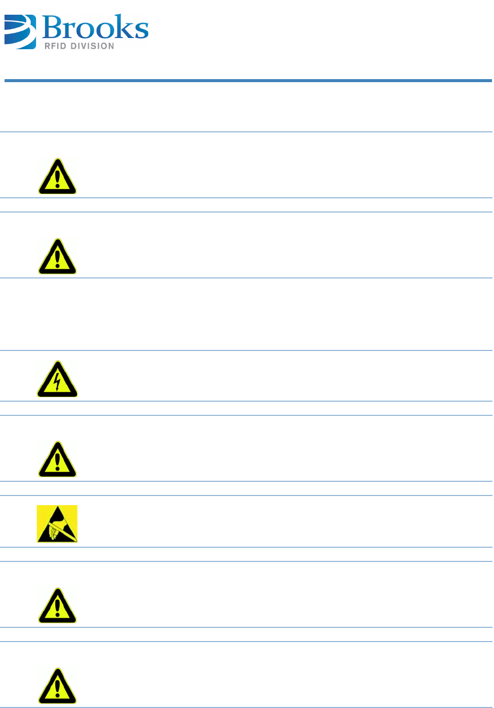
Product Manual - RFID Reader UF80 71
Chapter 8
Service and Troubleshooting
8.2 Qualified troubleshooting personnel
8.3 Safety instructions
CAUTION Error handling must only be carried out by specially trained personnel. If you
are uncertain about the qualifications that are required, contact the
manufacturer.
CAUTION Error handling of the device without the special skills required and unqualified
interference with the device can result in personal injury and damage to the
reader and/or connected devices.
All antenna resonant circuit components carry high voltages.
WARNING When replacement parts are required, use only manufacturer-specified parts.
Unauthorized substitution of parts can result in fire, electric shock or other
hazards.
Electrostatic charges can damage electronic components within the device.
ESD protective measures must be applied when opening the device ( ESD
instructions).
CAUTION When removing the cover, consider that the cover may be attached to the
device by a cable (LED).
Carefully remove the cover to prevent damage. Do not operate the device when
the cover is open!
CAUTION Never short circuit the fuse! This may result in fire or damage on the device.
Only use fuses specified by the manufacturer.
nbb

Product Manual - RFID Reader UF80 72
Chapter 8
Service and Troubleshooting
8.4 Error codes
Error
ID Name Description Possible causes Correcting action
0none no error not used no
1auto fail automatic reading is not
possible1)
reader is still busy
with a former read or
write request
wait until the former request
is done
2ex fail read or write initiated
from the host, and/or
other actions cannot be
carried out1)
reader is still busy
with a former read or
write request
wait until the former request
is done
3write fail data transfer to the tag
not possible1)
reader is still busy
with a former read or
write request
wait until the former request
is done
4no tag no tag or antenna
installed
no readable tag at
the reading range
bring a tag into the range of
the antenna; verify type and
function of the tag
antenna is not
connected correctly
check connection of the
antenna
bad orientation
between antenna and
tag
check orientation between
antenna and tag (see
section antenna installation
and antennas)
antenna is not tuned perform an antenna tuning
(see section installation ->
DIP switches)
disrupting field at
transmitting freqency
check surronding of antenna
for possible disrupting
sources (monitors , servo
motors...)
antenna is damaged
or too close to metal
replace antenna, verify
antenna installation
5invalid invalid parameter or
data
data sent with a
command are wrong
check syntax and data of
command
sent parameter is not
implemented or out
of range
check syntax and value of
parameter

Product Manual - RFID Reader UF80 73
Chapter 8
Service and Troubleshooting
6unknown unknown error not used no
7unconfig the device is not
configured
wrong reader address
was sent
check syntax of message,
check parameter F "Reader
address"
8check parity and/or checksum
error
wrong baud rate is
set
check baud rate of serial
interface (COM port)
transmision errors on
serial communication
check RS232 cable and
connectors; check disrupting
sources at RS232
9void
ackn
no valid acknowledge
(unexpected
acknowledge)
double or wrong
acknowledgement
check host communication
settings
serial communication
is interupted
check RS232 cable and
connectors; check disrupting
sources at RS232
Alocked locked page cannot be
written
page to be written is
locked (write
protected forever)
check page number to write;
replace tag with new one
:msg len message too long or too
short, or message is not
received in full
length of message is
longer than shown at
the length byte
check message length,
check length byte
no valid end sign of
message (End sign
0x0D) detected
check syntax of message
not all characters are
transmitted
(Intercharacter
timeout)
check syntax of message,
check RS232 connection
;invalid invalid command unknown command
was sent
check syntax of command
Error
ID Name Description Possible causes Correcting action

Product Manual - RFID Reader UF80 74
Chapter 8
Service and Troubleshooting
1) because the device is still busy or because a message has not been confirmed
by the previous read up to now.
8.5 Error display with LEDs
Power LED does
not light up
8.6 Reader does not respond
Bno ackn the message which has
to be confirmed has
been sent the maximum
number of times (rs232
maxrepeat), and has
not been confirmed by
the terminal within the
defined time frame (see
parameter 5)
Host system does not
acknowledge the
message
check availability of host
system (terminal); check
RS232 cables and
connectors
Error
ID Name Description Possible causes Correcting action
Check the power supply and the connecting cables!
If the LED does not light up, disconnect the device from the power supply
and carefully remove the fuse! Test the fuse. If it is defective, replace it
with a fuse specified by the manufacturer!
If the above measures do not solve the problem, leave the device
disconnected and contact the manufacturer!
Check if the Ethernet cable is undamaged and correctly connected to both
reader and host!
Check the status as indicated by the LED!
Contact Brooks Automation (Germany) GmbH regarding the firmware of
the device and the firmware update software!
If these measures do not solve the problem, contact the manufacturer!

Product Manual - RFID Reader UF80 75
Chapter 8
Service and Troubleshooting
8.7 Reset
8.8 Power cut
After a power cut, the reader performs a self-test (see Reset).
8.9 SCT configuration transponder
Devices from software version UF80V1.1 support a stationary SCT configuration
transponder, which is connected to the cover plate. This variant is available as an
option.
If the support of the configuration transponder is activated via parameter 0x40
(see Parameter 64 (0x40)), the configuration transponder is read out at the
end of a reset procedure. If the read operation of the configuration transponder
was valid, the device is set according to the data of the configuration transponder.
This may result in a flash update of the reader. If, however, a configuration
transponder that contains invalid data was detected, the data are transferred
from the reader to the configuration transponder. At the end of the transfer, the
configuration transponder is marked as valid. As regards the support of the
configuration transponder, the configuration transponder may also be updated in
case of a subsequent parameterization of the device e.g. via a command. This
depends on whether the parameter to be set is also contained in the configuration
transponder. After the start procedure of the reader has been completed, the
three LEDs on the top of the device show the course of the start procedure for 5
seconds, and the device can then be used in a normal way. Furthermore, a query
of parameter 0x41 can at any time provide information as to the course of the
last start procedure of the reader. Refer to the description of parameter 0x41 (see
Parameter 65 (0x41)).
In the case of a malfunction, a hardware reset can be performed by briefly
interrupting the power supply.
During the reset, a self-test is performed, and the red, yellow and green
LED light up briefly.
If the configuration transponder is activated, a read operation of the
configuration transponder is then initiated and the result is shown
accordingly via the three LEDs.
At the end of the reset procedure, the buzzer makes a brief sound.

Product Manual - RFID Reader UF80 76
Chapter 8
Service and Troubleshooting
Flashing pattern
parameter 0x41
0x01 … The configuration transponder was not analyzed when the reader
was started.
LED pattern: yellow LED flashes with 5 Hz
0x02 … No configuration transponder could be read.
LED pattern: red LED flashes with 1 Hz
0x03 … Several configuration transponders could be read.
LED pattern: red LED flashes with 1 Hz
0x04 … A data range of the configuration transponder could not be read.
LED pattern: red LED flashes with 1 Hz
0x05 … The configuration transponder could be read and the device settings
were up to date.
LED pattern: green LED flashes with 5 Hz
0x06 … The configuration transponder could be read and the device settings
were adapted.
LED pattern: green LED on permanently and yellow LED flashes with 1 Hz
0x07 … Due to invalid configuration data, the configuration transponder with the
up-to-date device setting was successfully written on.
LED pattern: green LED on permanently and yellow LED flashes with 5 Hz
0x08 … Due to invalid configuration data, it was attempted to
adapt the configuration transponder with the up-to-date device setting,
which failed.
LED pattern: red LED flashes with 5 Hz
At the present time, only the stationary configuration transponder V0 is
supported, which contains the following settings:
IP address, subnet address, gateway address, DHCP and buzzer volume
8.10 Software releases
ETSI
Release
date Version Description
May 2011 UF80V1.0 First version
August 2011 UF80V1.1 Additional commands implemented
Support configuration transponder

Product Manual - RFID Reader UF80 77
Chapter 8
Service and Troubleshooting
FCC
8.11 Customer service
Brooks Automation (Germany) GmbH
RFID Division
Gartenstr. 19
D-95490 Mistelgau
GERMANY
Telephone +49 (0) 9279 - 991 550
Fax +49 (0) 9279 - 991 501
E-mail rfid.support@brooks.com
24 hour technical support hotline (Brooks):
USA and Canada +1 978 262 2900
Europe +49 1804 2255 4887
Japan +81 45 477 5980
China +86 21 5131 7066
Taiwan +886 3 5525225
Korea +82 31 288 2500
Singapore +65 6464 1481
Release
date Version Description
June 2012 UF80U1.0 First version

Product Manual - RFID Reader UF80 78
Chapter 9
Dismantling and Storage
9 Dismantling and Storage
This chapter gives you an overview of the following topics:
■ Dismantling
■ Storage
9.1 Dismantling
9.2 Storage
Store the reader and its components in a clean and dry environment with the
power supply disconnected.
Make sure the contacts remain clean. Observe the necessary storage conditions.
Remove the power supply!
Remove all cables!
Loosen and remove the mounting screws!
Remove the device from the installation area!

Product Manual - RFID Reader UF80 79
Chapter 10
Transport and Disposal
10 Transport and Disposal
This chapter gives you an overview of the following topics:
■ Transport
■ Disposal
10.1 Transport
For transportation purposes such as mailing, use a firm cardboard box.
Use adequate padding material to protect the device on all sides.
10.2 Disposal
Disconnect the electronic components from the housing and dispose of them as
follows:
■the housing as scrap metal
■the electronic components, antennas and cables as electronic waste
The device and its components are made of various materials.
Dispose of these materials separately, and observing the legal regulations of
your country.
Do not dispose of the device in regular household waste.
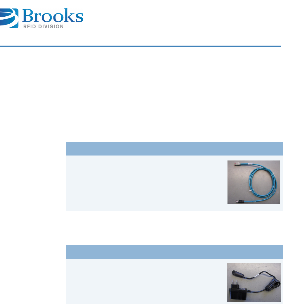
Product Manual - RFID Reader UF80 80
Chapter 11
Accessories
11 Accessories
This chapter gives you an overview of the following topics:
■ Cables
■ Power supply
11.1 Cables
11.2 Power supply
Type Part number Figure
Cable for Ethernet connection
(Cable length: 2,000 mm)
EKC5-20-SM12D-RJ45
Type Part number Figure
Power supply 24 V, 0.33 A
(IN: 100-240 V
OUT: 24 V / 0.33 A)
SVG0,3

Index
A
Access word 34
Antenna 28
Assembly 27
D
Data words 34
DHCP 34
E
E - Error message 54
EPC 35
Ex flag 35
Extensions 36
F
F - Query parameters 49
Frame ID 36
G
GW-ADR 36
H
H - Heartbeat 55
Head ID 36
High byte 32
Host name 37
Humidity 24
I
Installation dimensions 27
IP-ADR 37
K
K - Polling 57
L
Length 37, 38
Liability 12
Low byte 32
M
M - Scan EPCs 43
Memory address 38
Memory bank 38
Message 31
N
N - Reset 51

Index
Number of data words 39
O
O - Set output 52
Output state 39
P
P - Set parameter 50
Parameter 11 - Reader ID 65
Parameter 118 - Extended result flag 68
Parameter 12 - Acknowledgment error message 65
Parameter 123 - Fine version 68
Parameter 158 - Tag comm initial Q 68
Parameter 16 - Attenuation of transmission output 65
Parameter 162 - UHF asic parameter Tx driver current 68
Parameter 163 - UHF asci parameter Rx gain 69
Parameter 176 - TCP keep alive 69
Parameter 39 - Polling frequency 66
Parameter 4 - Delay time 65
Parameter 43 - Polling fallout 66
Parameter 47 - Polling mode 66
Parameter 48 - Buzzer delay 66
Parameter 50 - Buzzer volume 66
Parameter 6 - MaxRepeat 65
Parameter 64 - Support configuration transponder 67
Parameter 65 - Result code start procedure 67
Parameter 66 - MaxRepeat scan configuration transponder 68
Parameter 98 - Query temperature of the processor 68
Parameter 99 - Default parameter 68
Parameter no. 39
Parameter value 39
Power supply 28
Prohibition symbols 15
R
Reader ID 40
Relative humidity 24
Response code 40
Result 40
S
Safety instructions 14
Safety symbols 14
Serial number 40
Software version 41
T
Temperature 24
Transponder error code 41

Index
U
UFD - Query DHCP Enabled 58
UFI - Query network settings 60
UFN - Query host name 62
ULZ - Locking all EPC transponders (defined EPC code) 48
UPD - Set DHCP Enabled 59
UPI - Set network settings 61
UPN - Set host name 63
URY - Read data area (defined EPC code) 42
V
V - Query software version 56
W
W - Write EPC code 45
Warning symbols 15