Brother Fd4 B271 Owner S Manual
Brother-Ke-434C-Owner-S-Manual brother-ke-434c-owner-s-manual
Brother-Ke-436B-Owner-S-Manual brother-ke-436b-owner-s-manual
T-8750C Basic Instructions T-8750C BASIC INSTRUCTIONS T-8750C BASIC INSTRUCTIONS BROTHER a.teamworksales.com
2014-07-05
: Brother Brother-Fd4-B271-Owner-S-Manual brother-fd4-b271-owner-s-manual brother pdf
Open the PDF directly: View PDF ![]() .
.
Page Count: 40
- COVER
- SAFETY INSTRUCTIONS
- CONTENTS
- 1. USEFUL FUNCTIONS FOR OPTIMUM SEWING
- 2. NAMES OF MAJOR PARTS
- 3. INSTALLATION
- 4. PREPARATION BEFORE SEWING
- 5. USING THE G50 OPERATION PANEL(BASIC OPERATIONS)
- 6. SEWING
- Document CD
T-8421C, 8422C
T-8452C, 8722C
T-8752C
TWIN NEEDLE DIRECT DRIVE LOCK STITCHER
Please read this manual before using the machine.
Please keep this manual within easy reach for quick reference.
This basic operation manual describes basic
operations including sewing machine operations.
For cleaning, standard adjustments and more details,
please refer to the instruction manual contained in
the Document CD.
Basic Operation Manual
T-8421C, 8422C, 8452C, 8722C, 8752C
Thank you very much for buying a BROTHER sewing machine. Before using your new machine,
please read the safety instructions below and the explanations given in the instruction manual.
With industrial sewing machines, it is normal to carry out work while positioned directly in front of
moving parts such as the needle and thread take-up, and consequently there is always a danger of
injury that can be caused by these parts. Follow the instructions from training personnel and
instructors regarding safe and correct operation before operating the machine so that you will know
how to use it correctly.
T-8421C, 8422C, 8452C, 8722C, 8752C i
SAFETY INSTRUCTIONS
[1] Safety indications and their meanings
This instruction manual and the indications and symbols that are used on the machine itself are provided in order to ensure
safe operation of this machine and to prevent accidents and injury to yourself or other people.
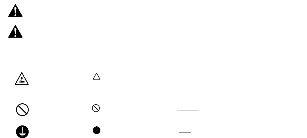
Indications
DANGER The instructions which follow this term indicate situations where failure to follow the
instructions may result in death or serious injury.
CAUTION The instructions which follow this term indicate situations where failure to follow the
instructions could cause injury when using the machine or physical damage to
equipment and surroundings.
Symbols
· · · · · This symbol ( ) indicates something that you should be careful of. The picture inside the triangle
indicates the nature of the caution that must be taken.
(For example, the symbol at left means “beware of injury”.)
· · · · · This symbol ( ) indicates something that you must not do.
· · · · · This symbol ( ) indicates something that you must do. The picture inside the circle indicates the
nature of the thing that must be done.
(For example, the symbol at left means “you must make the ground connection”.)
T-8421C, 8422C, 8452C, 8722C, 8752C
ii
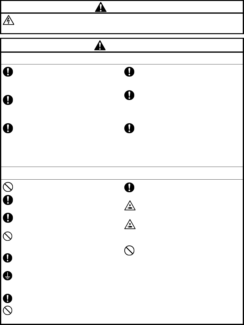
[2] Notes on safety
DANGER
Wait at least 5 minutes after turning off the power switch and disconnecting the power cord from the wall outlet
before opening the cover of the control box. Touching areas where high voltages are present can result in severe
injury.
CAUTION
Environmental requirements
Use the sewing machine in an area which is free
from sources of strong electrical noise such as
electrical line noise or static electric noise.
Sources of strong electrical noise may cause
problems with correct operation.
Any fluctuations in the power supply voltage
should be within ±10% of the rated voltage for the
machine.
Voltage fluctuations which are greater than this
may cause problems with correct operation.
The power supply capacity should be greater than
the requirements for the sewing machine's power
consumption.
Insufficient power supply capacity may cause
problems with correct operation.
The ambient temperature should be within the
range of 5°C to 35°C during use.
Temperatures which are lower or higher than this
may cause problems with correct operation.
The relative humidity should be within the range of
45% to 85% during use, and no dew formation
should occur in any devices.
Excessively dry or humid environments and dew
formation may cause problems with correct
operation.
In the event of an electrical storm, turn off the power
and disconnect the power cord from the wall outlet.
Lightning may cause problems with correct
operation.
Installation
Machine installation should only be carried out by
a qualified technician.
Contact your Brother dealer or a qualified
electrician for any electrical work that may need to
be done.
The sewing machine weighs approximately 50 kg
(110 lb). The installation should be carried out by
two or more people.
Do not connect the power cord until installation is
complete. The machine may operate if the treadle
is depressed by mistake, which could result in
injury.
Turn off the power switch before inserting or
removing the plug, otherwise damage to the
control box could result.
Be sure to connect the ground. If the ground
connection is not secure, you run a high risk of
receiving a serious electric shock, and problems
with correct operation may also occur.
When securing the cords, do not bend the cords
excessively or fasten them too hard with staples,
otherwise there is the danger that fire or electric
shocks could occur.
If using a work table which has casters, the casters
should be secured in such a way so that they
cannot move.
Secure the table so that it will not move when tilting
back the machine head. If the table moves, it may
crush your feet or cause other injuries.
Use both hands to hold the machine head when
tilting it back or returning it to its original position. If
only one hand is used, the weight of the machine
head may cause your hand to slip, and your hand
may get caught.
Be sure to wear protective goggles and gloves
when handling the lubricating oil and grease, so that
they do not get into your eyes or onto your skin,
otherwise inflammation can result.
Furthermore, do not drink the oil or eat the grease
under any circumstances, as they can cause
vomiting and diarrhea.
Keep the oil out of the reach of children.
T-8421C, 8422C, 8452C, 8722C, 8752C iii
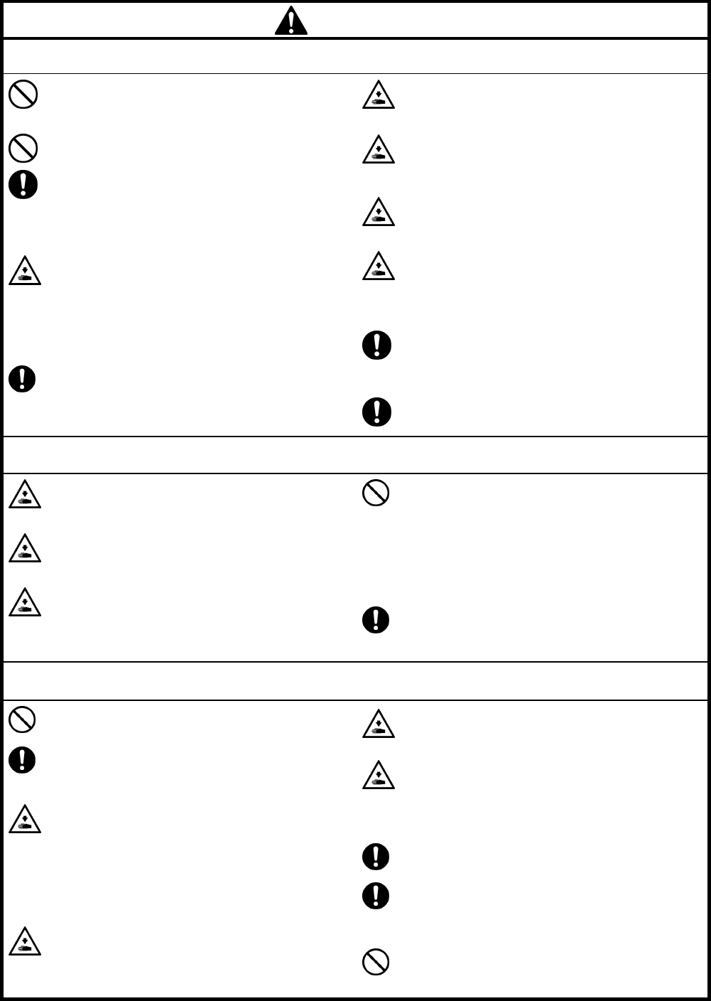
CAUTION
Sewing
This sewing machine should only be used by
operators who have received the necessary training
in safe use beforehand.
The sewing machine should not be used for any
applications other than sewing.
Be sure to wear protective goggles when using the
machine.
If goggles are not worn, there is the danger that if a
needle breaks, parts of the broken needle may
enter your eyes and injury may result.
Turn off the power switch at the following times.
The machine may operate if the treadle is
depressed by mistake, which could result in injury.
y When threading the needle
y When replacing the bobbin and needle
y When not using the machine and when leaving
the machine unattended
If using a work table which has casters, the casters
should be secured in such a way so that they
cannot move.
Attach all safety devices before using the sewing
machine. If the machine is used without these
devices attached, injury may result.
Do not touch any of the moving parts or press any
objects against the machine while sewing, as this
may result in personal injury or damage to the
machine.
Secure the table so that it will not move when tilting
back the machine head. If the table moves, it may
crush your feet or cause other injuries.
Use both hands to hold the machine head when
tilting it back or returning it to its original position. If
only one hand is used, the weight of the machine
head may cause your hand to slip, and your hand
may get caught.
If an error occurs in machine operation, or if
abnormal noises or smells are noticed, immediately
turn off the power switch. Then contact your nearest
Brother dealer or a qualified technician.
If the machine develops a problem, contact your
nearest Brother dealer or a qualified technician.
Cleaning
Turn off the power switch before carrying out
cleaning. The machine may operate if the treadle is
depressed by mistake, which could result in injury.
Secure the table so that it will not move when tilting
back the machine head. If the table moves, it may
crush your feet or cause other injuries.
Use both hands to hold the machine head when
tilting it back or returning it to its original position. If
only one hand is used, the weight of the machine
head may cause your hand to slip, and your hand
may get caught.
Be sure to wear protective goggles and gloves
when handling the lubricating oil and grease, so that
they do not get into your eyes or onto your skin,
otherwise inflammation can result.
Furthermore, do not drink the oil or eat the grease
under any circumstances, as they can cause
vomiting and diarrhea.
Keep the oil out of the reach of children.
Use only the proper replacement parts as specified
by Brother.
Maintenance and inspection
Maintenance and inspection of the sewing machine
should only be carried out by a qualified technician.
Ask your Brother dealer or a qualified electrician to
carry out any maintenance and inspection of the
electrical system.
Turn off the power switch and disconnect the power
cord from the wall outlet at the following times,
otherwise the machine may operate if the treadle is
depressed by mistake, which could result in injury.
y When carrying out inspection, adjustment and
maintenance
y When replacing consumable parts such as the
rotary hook
If the power switch needs to be left on when
carrying out some adjustment, be extremely careful
to observe all safety precautions.
Secure the table so that it will not move when tilting
back the machine head. If the table moves, it may
crush your feet or cause other injuries.
Use both hands to hold the machine head when
tilting it back or returning it to its original position.
If only one hand is used, the weight of the machine
head may cause your hand to slip, and your hand
may get caught.
Use only the proper replacement parts as specified
by Brother.
If any safety devices have been removed, be
absolutely sure to re-install them to their original
positions and check that they operate correctly
before using the machine.
Any problems in machine operation which result
from unauthorized modifications to the machine will
not be covered by the warranty.
T-8421C, 8422C, 8452C, 8722C, 8752C
iv
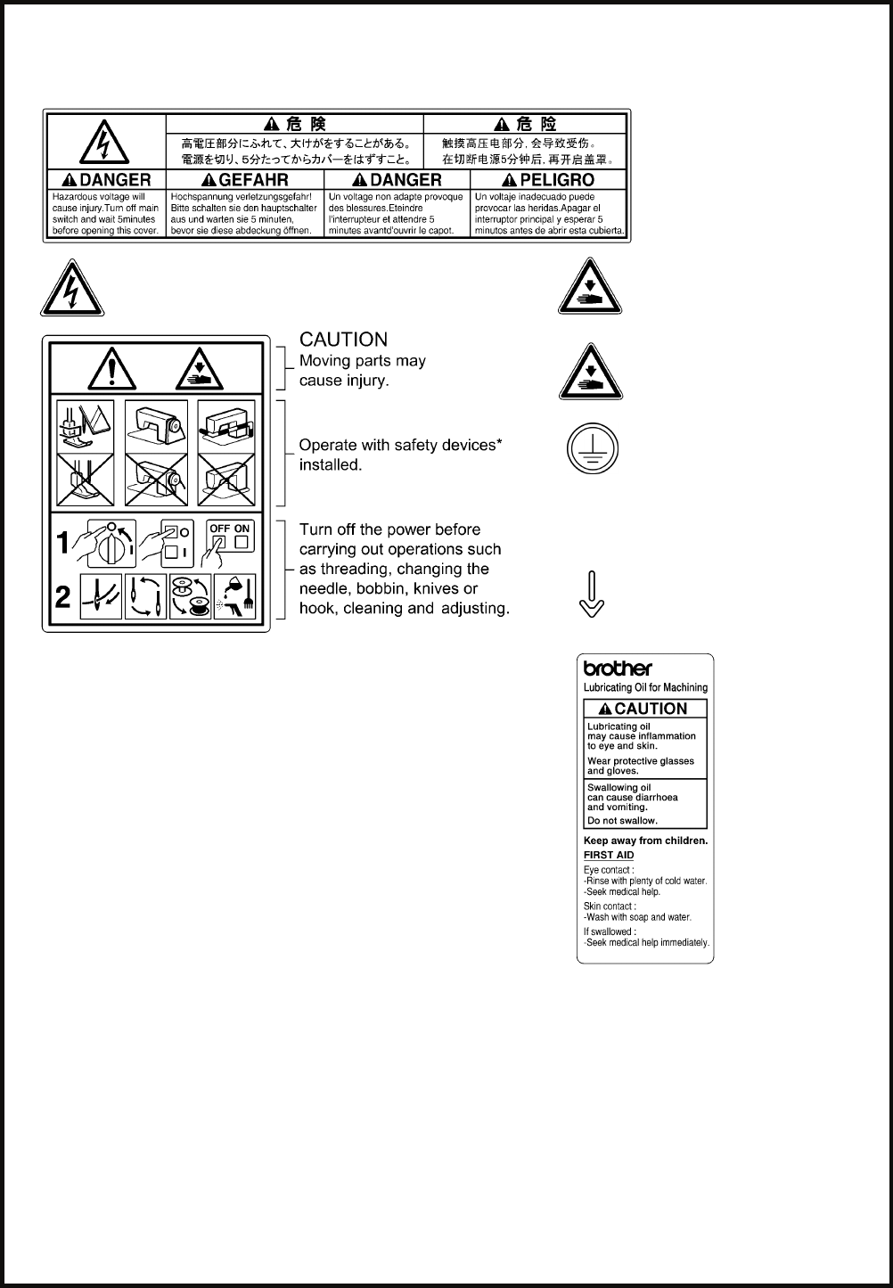
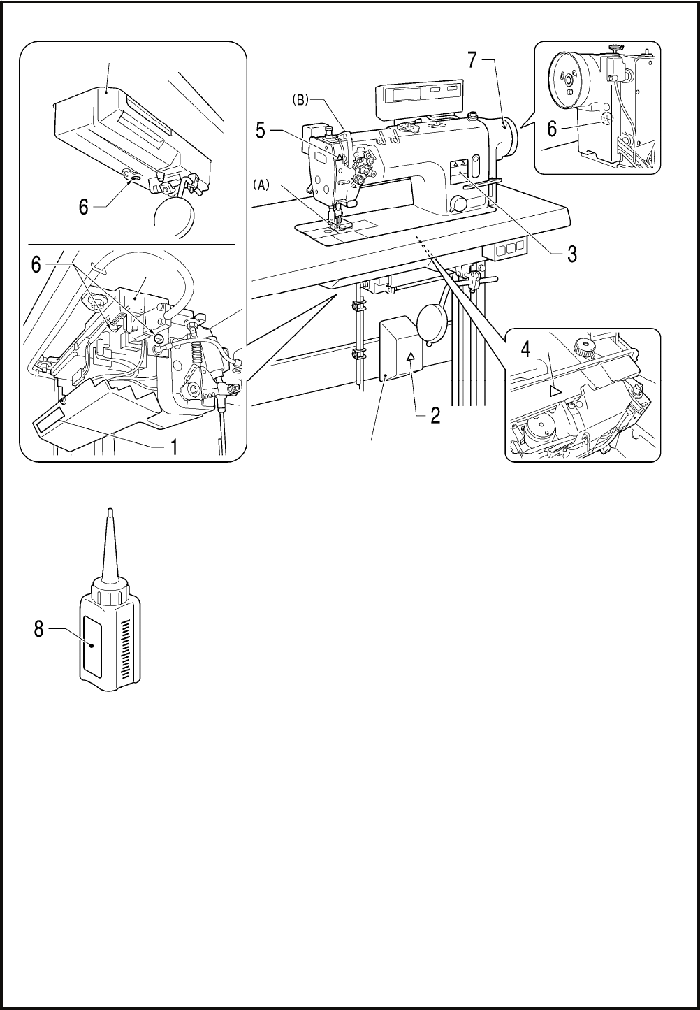
[3] Warning labels
The following warning labels appear on the sewing machine.
Please follow the instructions on the labels at all times when using the machine. If the labels have been removed or are
difficult to read, please contact your nearest Brother dealer.
1
2 Touching areas where high voltages are present can
result in severe injury. Turn off the power before
opening the cover.
4 Be careful not to get your hands
caught when returning the
machine head to its original
position after it has been tilted.
3 5
Be careful to avoid injury from
the moving thread take-up.
6 Be sure to connect the ground. If
the ground connection is not
secure, you run a high risk of
receiving a serious electric
shock, and problems with correct
operation may also occur.
7 Direction of operation
* Safety devices: (A) Finger guard
(B) Thread take-up cover 8
PE
T-8421C, 8422C, 8452C, 8722C, 8752C v
Control box
Oil pan
2166B
Transformer box
(100V/400V system only)
Oil tank 2506B
T-8421C, 8422C, 8452C, 8722C, 8752C
CONTENTS
1. USEFUL FUNCTIONS FOR OPTIMUM
SEWING................................................ 1
2. NAMES OF MAJOR PARTS ................ 2
3. INSTALLATION.................................... 3
3-1. Table processing diagram .............................. 4
3-2. Installation ...................................................... 4
3-3. Lubrication ...................................................... 8
3-4. Connecting the cords...................................... 10
3-4-1. Opening the control box cover............ 10
3-4-2. Connecting the cords .......................... 10
3-5. Test operation (Operating the treadle) ........... 15
3-6. Adjusting the treadle operation....................... 16
4. PREPARATION BEFORE SEWING.....17
4-1. Installing the needle........................................... 17
4-2. Removing the bobbin...................................... 18
4-3. Winding the lower thread................................ 19
4-4. Installing the bobbin........................................ 20
4-5. Threading the upper thread............................ 22
4-6. Adjusting the stitch length............................... 24
4-7. Using the knee lifter........................................ 24
4-8. Using the thread wiper
(models with thread trimmer only) .................. 24
4-9. Corner sewing method (T-8452C, 8752C) ..... 25
4-9-1. To stop the needle bars
(right and left) ..................................... 25
4-9-2. Number of stitches: quick-reference
guide ................................................... 25
5. USING THE G50 OPERATION PANEL
(BASIC OPERATIONS)........................26
5-1. Names and functions...................................... 26
5-2. Sewing start and end backtack stitches ......... 28
6. SEWING ...............................................29
6-1. Sewing ............................................................29
6-2. Backtacking.....................................................30
T-8421C, 8422C, 8452C, 8722C, 8752C
1. USEFUL FUNCTIONS FOR OPTIMUM SEWING
1
1. USEFUL FUNCTIONS FOR OPTIMUM SEWING
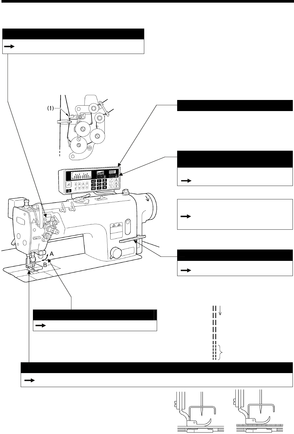
Thread take-up amount can be adjuste
INSTRUCTION MANUAL CD
10-5. Adjusting the thread take-up amount
Depending on the material and thread used, you can
reduce the thread take-up amount to suit the material
and thread being used by threading the thread through
the thread amount adjuster (1).
This can be useful if sewing with light material or if
using slippery thread such as polyester thread.
Selectable starting speed
The sewing speed at the sewing start can be
selected in accordance with the treadle
depression amount. You can set the speed
according to the preferences of the operator.
(Contact the place of purchase.)
Easy setting of sewing speed
from operation panel
< When using the G50 operation panel >
Page 27
The sewing speed can be adjusted using the
sewing speed control keys.
< When using the G10 operation panel >
INSTRUCTION MANUAL CD
8-5. Setting the maximum sewing
speed
The sewing speed can be adjusted using the
MAX key.
Condensed stitching
INSTRUCTION MANUAL CD
9-3. Sewing condensed stitches
This feature is ideal for use when sewing thin
materials that can easily pucker when reverse
stitches are sewn. Condensed stitches have a
smaller sewing pitch and they help prevent
fraying.
Actuator switch
Page 30
The actuator switch can be rotated 90 degrees as
shown in the illustration. Select the position (A or
B) that is easier to use.
Floating presser foot for easy handling
INSTRUCTION MANUAL CD
10-3. Adjusting the presser foot floating amount (minute lifting amount)
< G50 operation panel >
2511B
A micro-adjustable type floating presser foot is equipped as
standard. This device is ideal for controlling presser foot
floating in materials that stretch easily and materials with
long pile. It prevents seam slippage and also prevents
damage to the material. In addition, three-dimensional
articles with irregular curves can also be handled with ease.
2513B
2510B
Sewing direction
Condensed stitches
2512B
T-8421C, 8422C, 8452C, 8722C, 8752C
2. NAMES OF MAJOR PARTS
2
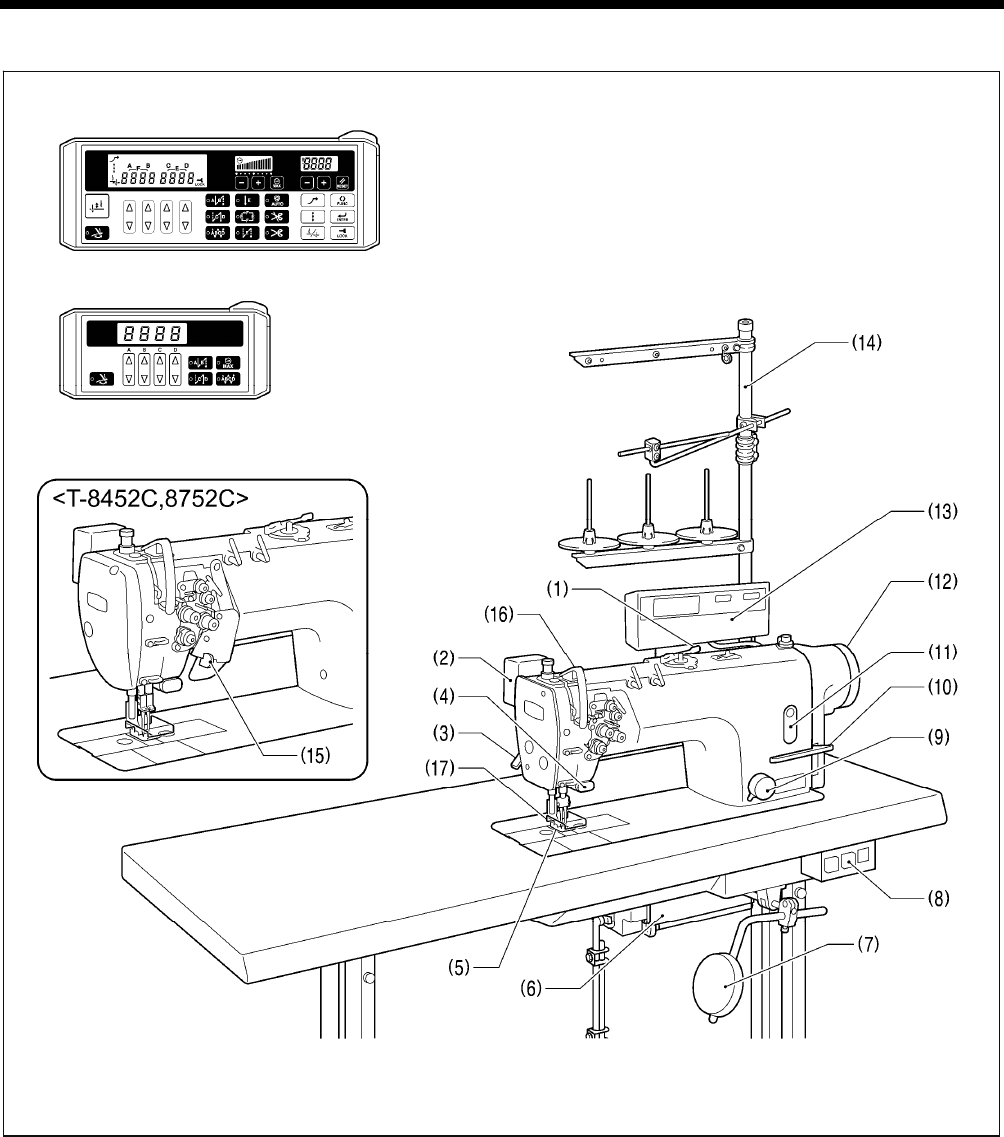
2. NAMES OF MAJOR PARTS
(1) Bobbin winder (2) Thread wiper (T-8422C, 8452C, 8722C, 8752C)
(3) Lifting lever (4) Quick reverse (Actuator switch)
(5) Presser foot (6) Control box
(7) Knee lifter assembly (8) Power switch
(9) Stitch length dial (10) Reverse lever
(11) Oil gauge window (12) Machine pulley
(13) Operation panel (14) Cotton stand
(15) Stop lever (T-8452C, 8752C )
Safety devices
(16) Thread take-up cover (17) Finger guard
2168B
G10 operation panel (basic function LED)
G50 operation panel (advanced function LCD)
T-8421C, 8422C, 8452C, 8722C, 8752C
3. INSTALLATION
3
3. INSTALLATION
CAUTION
Machine installation should only be carried out by a
qualified technician.
Contact your Brother dealer or a qualified electrician
for any electrical work that may need to be done.
The sewing machine weighs more than 50 kg. The
installation should be carried out by two or more
people.
Do not connect the power cord until installation is
complete. The machine may operate if the treadle is
depressed by mistake, which could result in injury.
Secure the table so that it will not move when tilting
back the machine head. If the table moves, it may
crush your feet or cause other injuries.
Use both hands to hold the machine head when
tilting it back or returning it to its original position. If
only one hand is used, the weight of the machine
head may cause your hand to slip, and your hand
may get caught.
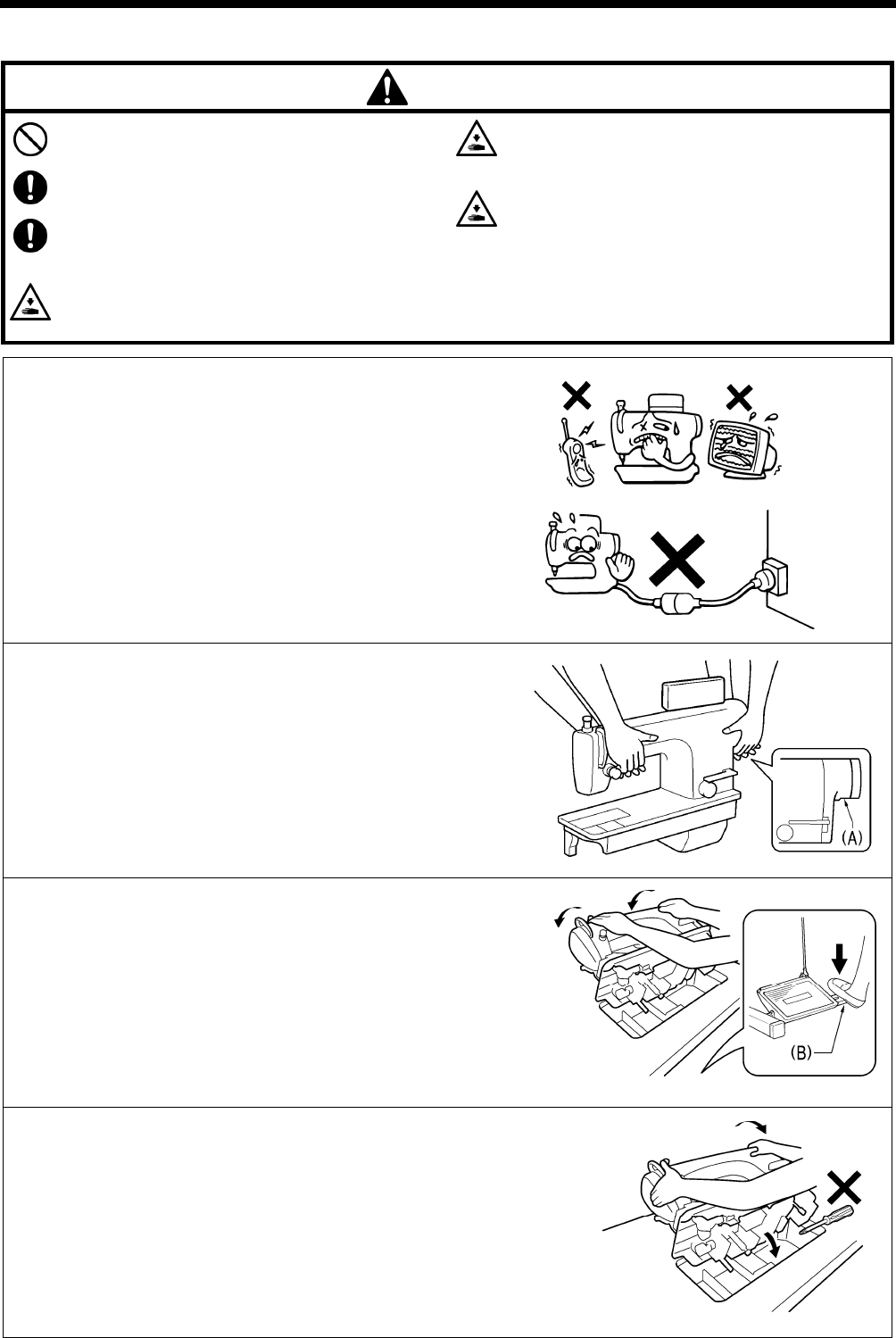
About the machine set-up location
Do not set up this sewing machine near other equipment such as
televisions, radios or cordless telephones, otherwise such
equipment may be affected by electronic interference from the
sewing machine.
The sewing machine should be plugged directly into an AC wall
outlet. Operation problems may result if extension cords are
used.
Carrying the machine
The machine should be carried by the arm by two people as
shown in the illustration.
* Hold the motor cover (A) by hand also so that the pulley does
not rotate.
Tilting back the machine head
Hold section (B) with your foot so that the table does not move,
and then push the arm with both hands to tilt back the machine
head.
Returning the machine head to the upright position
1. Clear away any tools, etc. which may be near the table holes.
2. While holding the face plate with your left hand, gently return the
machine head to the upright position with your right hand.
2086M
2871M
2872M
2169B
T-8421C, 8422C, 8452C, 8722C, 8752C
3. INSTALLATION
4
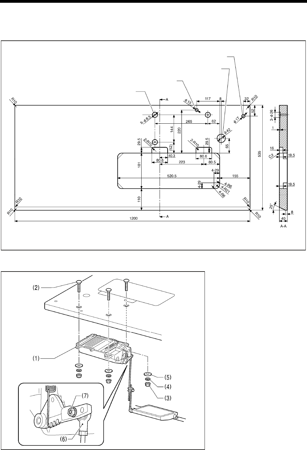
3-1. Table processing diagram
The top of the table should be 40 mm in thickness and should be strong enough to hold the weight and with-stand the
vibration of the sewing machine.
Drill holes as indicated in the illustration below.
3-2. Installation
1. Control box
(1) Control box
(2) Bolts [3 pcs]
(3) Nuts [3 pcs]
(4) Spring washers [3 pcs]
(5) Washers [3 pcs]
2. Connecting rod
(6) Connecting rod
(7) Nut
4127M
2170B
Cotton stand hole
Cord hole
Head rest hole
Control box mounting hole
T-8421C, 8422C, 8452C, 8722C, 8752C
3. INSTALLATION
5
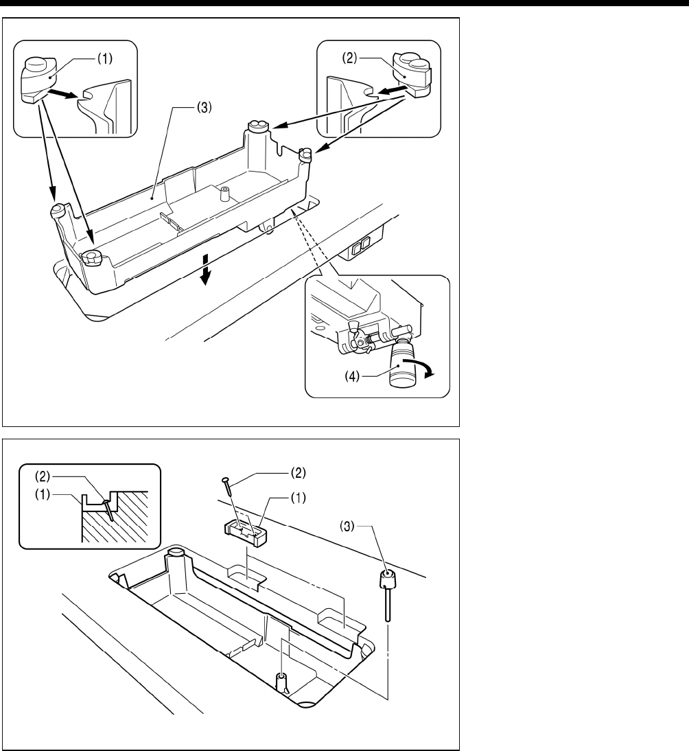
3. Oil pan
(1) Head cushions (left) [2 pcs]
(2) Head cushions (right) [2 pcs]
(3) Oil pan
(4) Oiler
4. Rubber cushions
(1) Rubber cushions [2 pcs]
(2) Nails [4 pcs]
5. Knee lifter complying bar
(3) Knee lifter complying bar
2874M
2875M
T-8421C, 8422C, 8452C, 8722C, 8752C
3. INSTALLATION
6
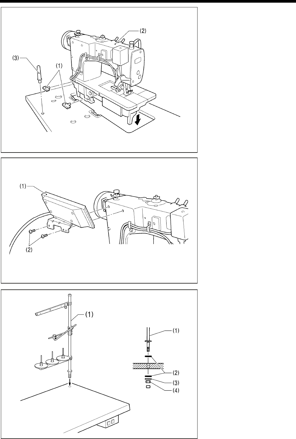
6. Machine head
(1) Hinges [2 pcs]
(2) Machine head
(3) Head rest
NOTE:
Tap the head rest (3) securely into
the table hole.
If the head rest (3) is not pushed in
as far as it will go, the machine head
will not be sufficiently stable when it
is tilted back.
7. Operation panel
(1) Operation panel
(2) Screws [2 pcs]
(Use for tightening rear cover)
8. Cotton stand
(1) Cotton stand
NOTE:
Securely tighten the nut (4) so that
the two rubber cushions (2) and the
washer (3) are securely clamped and
so that the cotton stand (1) does not
move.
2171B
2172B
2878M
T-8421C, 8422C, 8452C, 8722C, 8752C
3. INSTALLATION
7
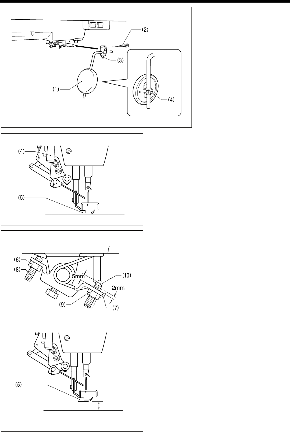
9. Knee lifter plate
(1) Knee lifter plate
(2) Bolt
* Loosen the bolt (3) and the bolt (4),
and move the knee lifter plate (1) to
a position where it is easy to use.
<Knee lifter adjustment>
1. Turn the machine pulley so that the feed dog is below the
top of the needle plate.
2. Lower the presser foot (5) by using the lifting lever (4).
3. Loosen the nut (6).
4. Turn the screw (8) to adjust so that the amount of play in
the knee lifter (7) is approximately 2 mm when the knee
lifter plate (1) is gently pressed.
5. Securely tighten the nut (6).
6. Loosen the nut (9).
7. Turn the screw (10) until the distance between the end of
the screw (10) and the knee lifter (7) is approximately 5
mm.
8. Turn the adjusting screw (10) to adjust so that the presser
foot (5) is at the desired position within a distance of 13
mm of the needle plate when the knee liter plate (1) is
fully pressed.
9. After adjustment is completed, securely tighten the nut
(9).
2173B
2880M
Within 13 mm
2882M
2881M
T-8421C, 8422C, 8452C, 8722C, 8752C
3. INSTALLATION
8
3-3. Lubrication
CAUTION
Do not connect the power cord until lubrication has been completed, otherwise the machine may operate if the
treadle is depressed by mistake, which could result in injury.
Be sure to wear protective goggles and gloves when handling the lubricating oil and grease, so that they do not get
into your eyes or onto your skin, otherwise inflammation can result.
Furthermore, do not drink the oil or eat the grease under any circumstances, as they can cause vomiting and
diarrhea.
Keep the oil out of the reach of children.
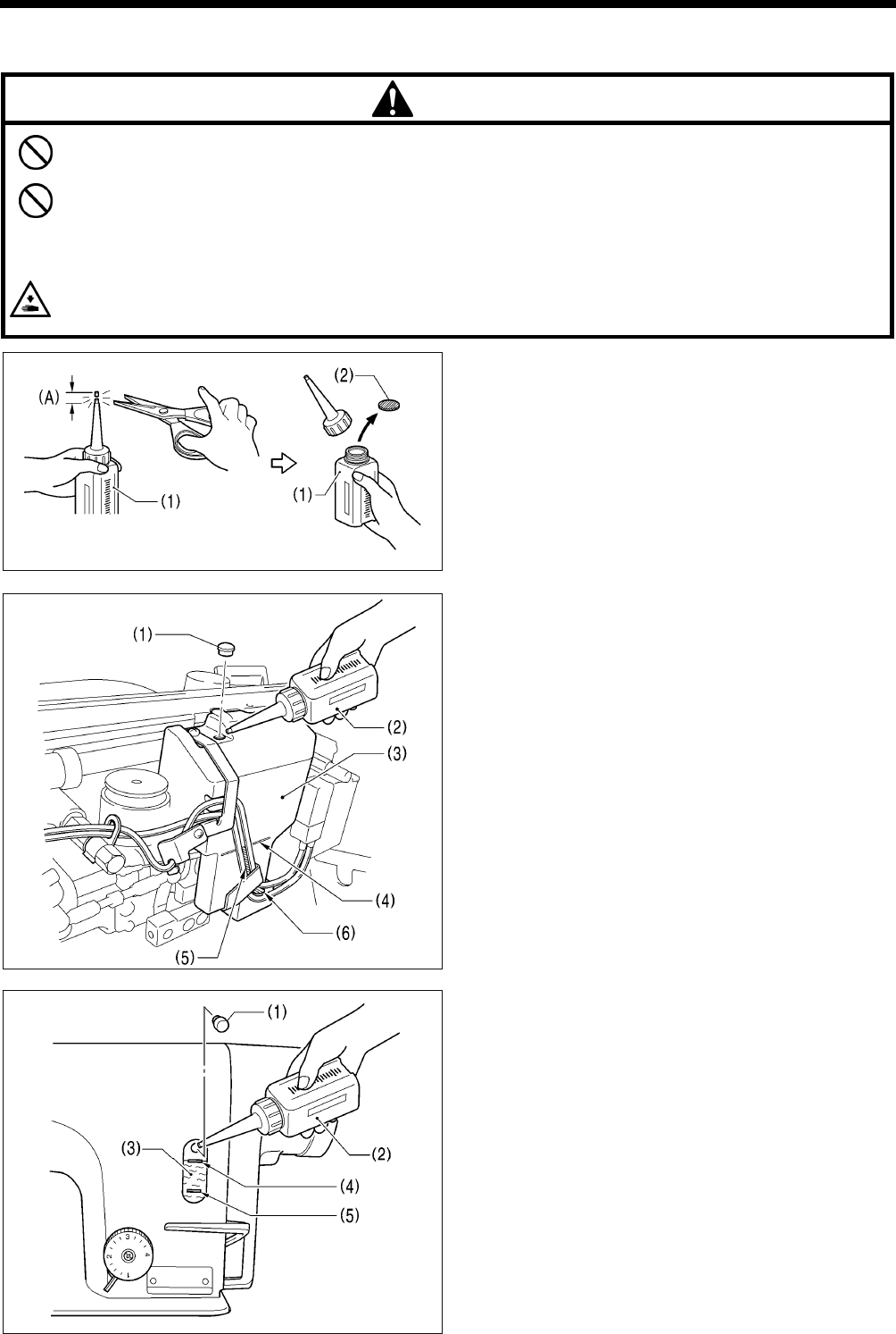
When cutting the nozzle of the oil tank, hold the base of the nozzle securely.
If you hold the end of the nozzle, injury from the scissors may result.
The sewing machine should always be lubricated and the
oil supply replenished before it is used for the first time,
and also after long periods of non-use.
Use only the lubricating oil <NIPPON OIL CORPORATION
Sewing Lube 10N; VG10> specified by Brother.
* If this type of lubricating oil is difficult to obtain, the recommended
oil to use is <Exxon Mobil Essotex SM10; VG10>.
1. Hold the base of the nozzle of the accessory oil tank (1),
and use scissors to cut about half-way along the straight
section (A) of the nozzle.
2. Loosen and remove the nozzle, and then remove the seal (2).
3. Tighten the nozzle.
<Lubricating via the oil cover>
1. Tilt back the machine head.
2. Remove the rubber cap (1).
3. Use the accessory oil tank (2) to pour lubricating oil into
the oil cover (3) until the oil level reaches the reference
line (4).
NOTE:
Do not fill with lubricating oil past the reference line (4).
If you pour in too much lubricating oil, it may spill out
when the machine head is tilted back.
4. Replace the rubber cap (1).
5. Return the machine head to its original position.
* If the lubricating oil level drops below the bottom (6) of the
oil gauge window (5), be sure to add more oil.
<Lubricating via the oil tank>
1. Remove the rubber cap (1).
2. Use the accessory oil tank (2) to pour in lubricating oil until
the oil level reaches the top reference line (4) of the oil
gauge window (3).
3. Replace the rubber cap (1).
* If the lubricating oil level drops below the bottom reference
line (5), be sure to add more oil.
2356B
2355B
2354B
T-8421C, 8422C, 8452C, 8722C, 8752C
3. INSTALLATION
9
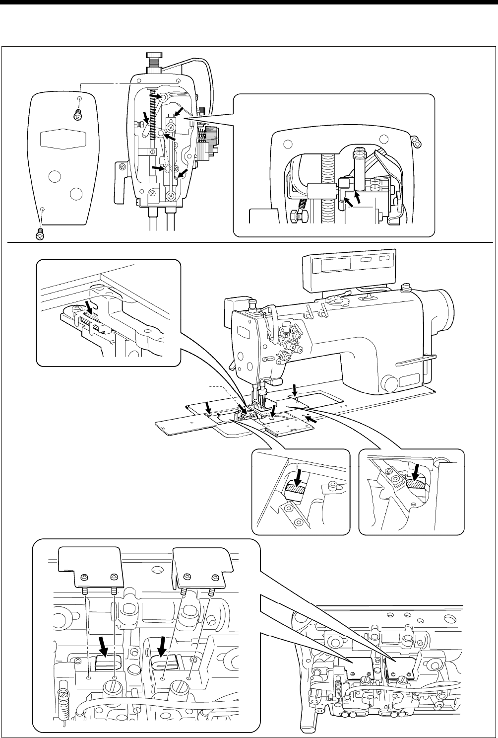
■Lubrication
Apply 1 - 2 drops of oil to the places indicated by the arrows.
2200B
Rotary hook race
(left and right)
2174B
2887M
<Semi dry type and minimum lubrication type>
<Minimum lubrication type only>
* Do not apply oil for semi dry types.
<T-8452C, 8752C>
T-8421C, 8422C, 8452C, 8722C, 8752C
3. INSTALLATION
10
3-4. Connecting the cords
DANGER
Wait at least 5 minutes after turning off the power switch and disconnecting the power cord from the wall outlet
before opening the face plate of the control box. Touching areas where high voltages are present can result in
severe injury.
CAUTION
Contact your Brother dealer or a qualified electrician
for any electrical work that may need to be done.
Do not connect the power cord until all cords have
been connected.
The machine may operate if the treadle is depressed
by mistake, which could result in injury.
When securing the cords, do not bend the cords
excessively or fasten them too hard with staples,
otherwise there is the danger that fire or electric
shocks could occur.
Be sure to connect the ground. If the ground
connection is not secure, you run a high risk of
receiving a serious electric shock, and problems with
correct operation may also occur.
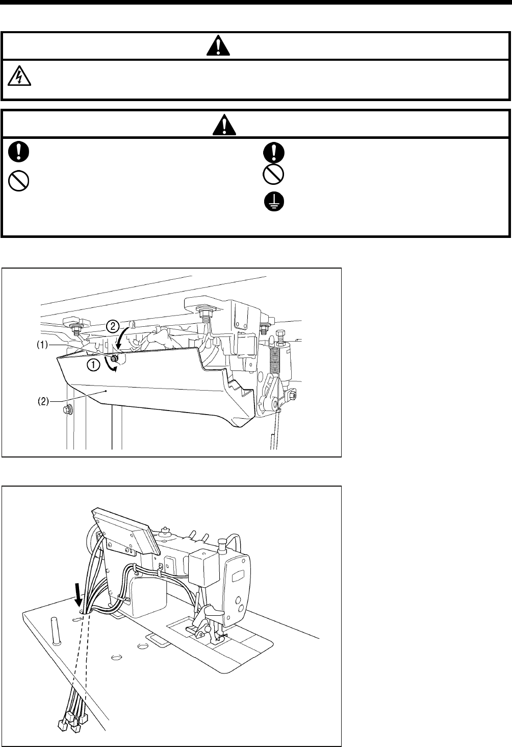
3-4-1. Opening the control box cover
(1) Screw
(2) Cover
3-4-2. Connecting the cords
1. Sewing machine cords
4137M
2175B
T-8421C, 8422C, 8452C, 8722C, 8752C
3. INSTALLATION
11
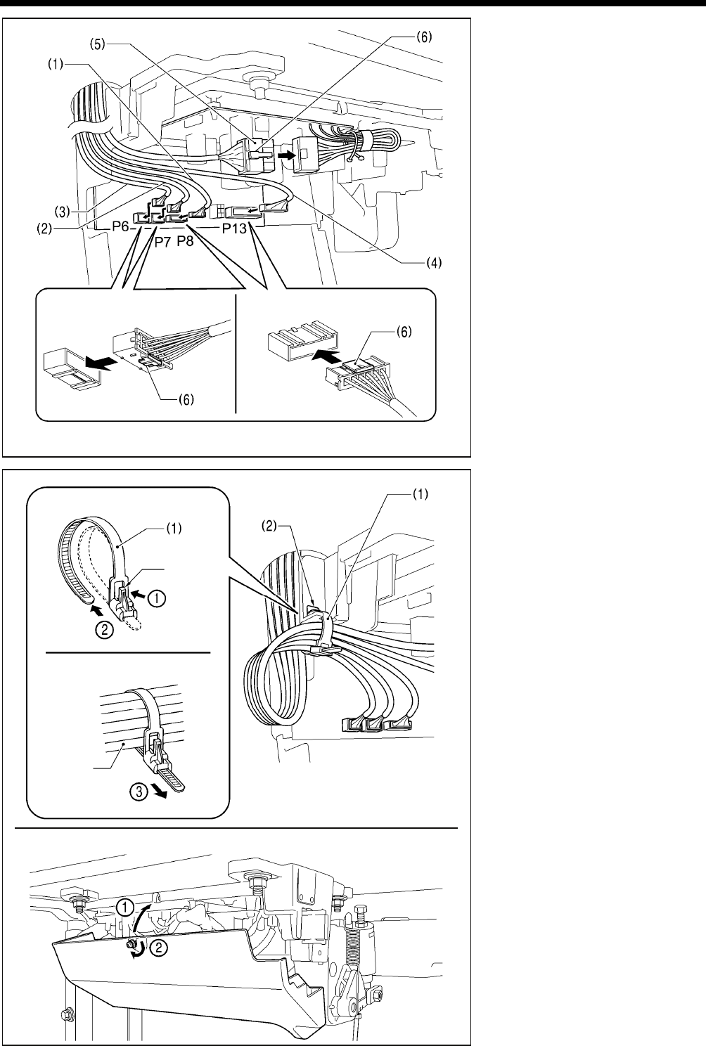
(1) 6-pin head detector unit connector
(2) 12-pin operation panel connector
(3) 10-pin resolver connector
(4) 14-pin machine connector
(5) 4-pin motor connector
2. Binding the cords
(1) Repeat cable tie
NOTE:
Bind the cords in such a way that the
connector does not get pulled out.
All cords that come out from the
control box should be secured to the
cord holder (2) using the repeat
cable tie (1), otherwise vibration from
the sewing machine may cause the
cords to become disconnected,
which can cause problems with the
operation of the control box.
4139M
Push in securely until the tabs (6) engage.
<Closing the cover>
4141M
<Removal>
<Securing>
Press
the tab.
Cords
4140M
Lower the tab (6). Raise the tab (6).
T-8421C, 8422C, 8452C, 8722C, 8752C
3. INSTALLATION
12
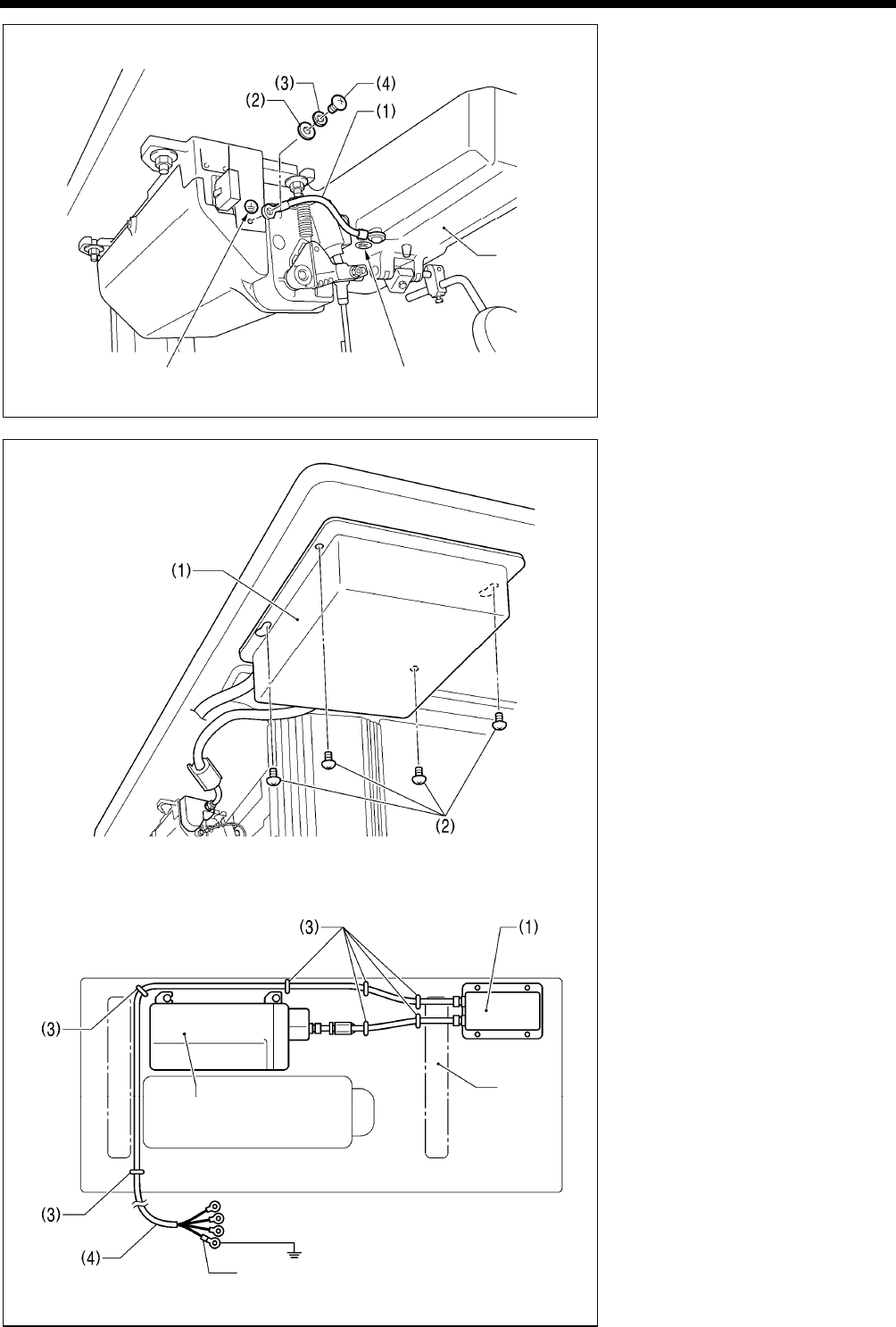
3. Ground wire
(1) Ground wire
(2) Washer
(3) Spring washer
(4) Screw
4. Other cords
Connect cords that match the voltage
specifications.
< Europe specifications >
(1) Filter box
(2) Screws [4 pcs.]
(3) Staples [7 pcs.]
(4) Power cord
1. Attach an appropriate plug to the
power cord (4). (The green and
yellow wire is the ground wire.)
2. Insert the power plug into a
properly-grounded electrical outlet.
NOTE:
Take care when tapping in the
staples (3) to make sure that they do
not pierce the cords.
Do not use extension cords,
otherwise machine operation
problems may result.
Oil pan
4143M
Green and yellow wire (ground wire)
<Seen from underneath table>
Control box
Leg
Ground symbol Ground symbol
2176B
4144M
T-8421C, 8422C, 8452C, 8722C, 8752C
3. INSTALLATION
13
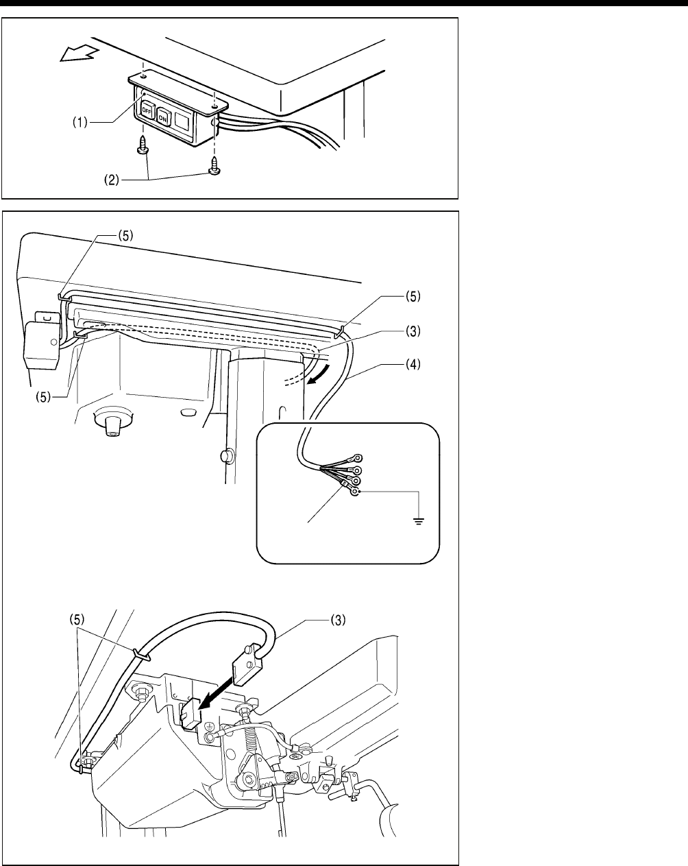
<200V system>
(1) Power switch
(2) Screws [2 pcs]
(3) 3-pin power supply connector
(4) Power cord
(5) Staples [5 pcs.]
1. Attach an appropriate plug to the
power cord (4). (The green and
yellow wire is the ground wire.)
2. Insert the power plug into a
properly-grounded electrical outlet.
NOTE:
Take care when tapping in the
staples (5) to make sure that they do
not pierce the cords.
Do not use extension cords,
otherwise machine operation
problems may result.
4145M
Green and yellow wire
(ground wire)
Operator
2178B
2177B
T-8421C, 8422C, 8452C, 8722C, 8752C
3. INSTALLATION
14
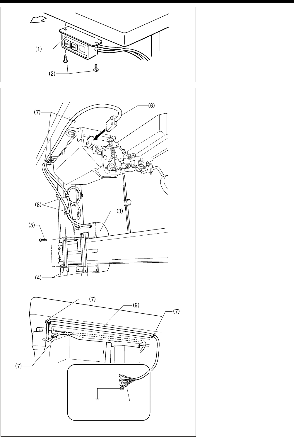
<100V/400V system>
(1) Power switch
(2) Screws [2 pcs]
(3) Transformer box
(4) Transformer box plates [2 pcs.]
(5) Screw [with washer]
(6) 3-pin power supply connector
(7) Staples [6 pcs.]
(8) Cord clamps [2 pcs.]
(9) Power cord
1. Attach an appropriate plug to the
power cord (9). (The green and
yellow wire is the ground wire.)
2. Insert the power plug into a
properly-grounded electrical outlet.
NOTE:
Take care when tapping in the
staples (7) to make sure that they do
not pierce the cords.
Do not use extension cords,
otherwise machine operation
problems may result.
Operator
4145M
2179B
Green and yellow wire
(ground wire)
2380B
T-8421C, 8422C, 8452C, 8722C, 8752C
3. INSTALLATION
15
3-5. Test operation (Operating the treadle)
CAUTION
Do not touch any of the moving parts or press any objects against the machine while sewing, as this may result in
personal injury or damage to the machine.
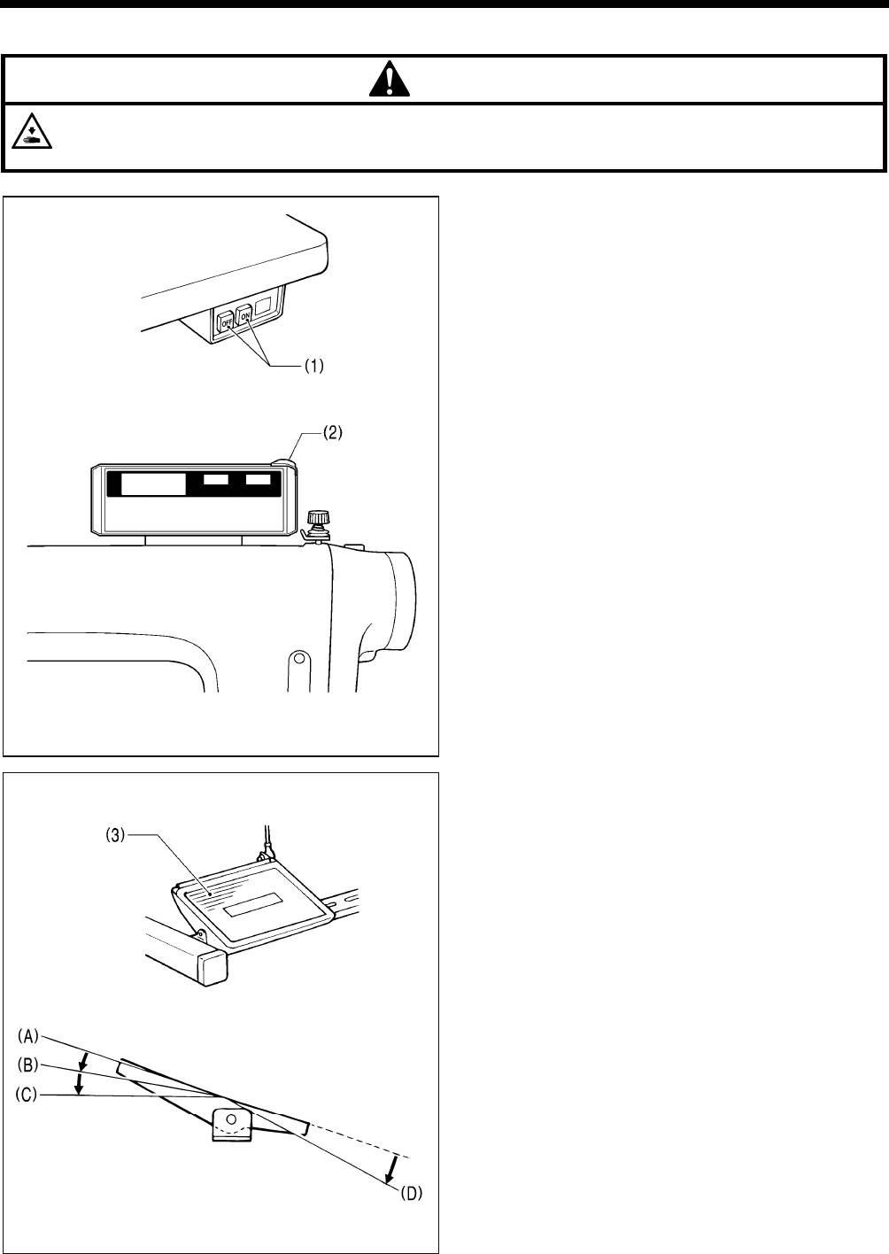
<Turning on the power>
Press the ON power switch (1).
The power indicator (2) will illuminate.
<Test operation>
1. Check that the machine sews at low speed when the
treadle (3) is gently pressed to position (B).
NOTE:
If the sewing machine does not operate even when the
treadle (3) is depressed, check the position of the safety
switch. (Refer to “13-1. Safety switch position” in the
instruction manual CD.)
2. Then check that it sews at high speed when the treadle
(3) is gently pressed to position (C).
3. After pressing the treadle (3) forward, check that the
needle is lowered to the top of the needle plate when the
treadle (3) is returned to the neutral position (A). (when
needle down stopping has been set.)
4. If the treadle (3) is pressed to position (D), (thread
trimming is carried out for models with thread trimmer)
and the needle rises above the needle plate and stops.
5. With the machine head tilted back, depress the treadle (3)
and check that the sewing machine does not operate.
NOTE:
If the sewing machine operates when the treadle (3) is
depressed while the machine head is tilted back, the
safety switch is probably faulty. Contact the place of
purchase.
2114M
2207B
2117M
2182B
T-8421C, 8422C, 8452C, 8722C, 8752C
3. INSTALLATION
16
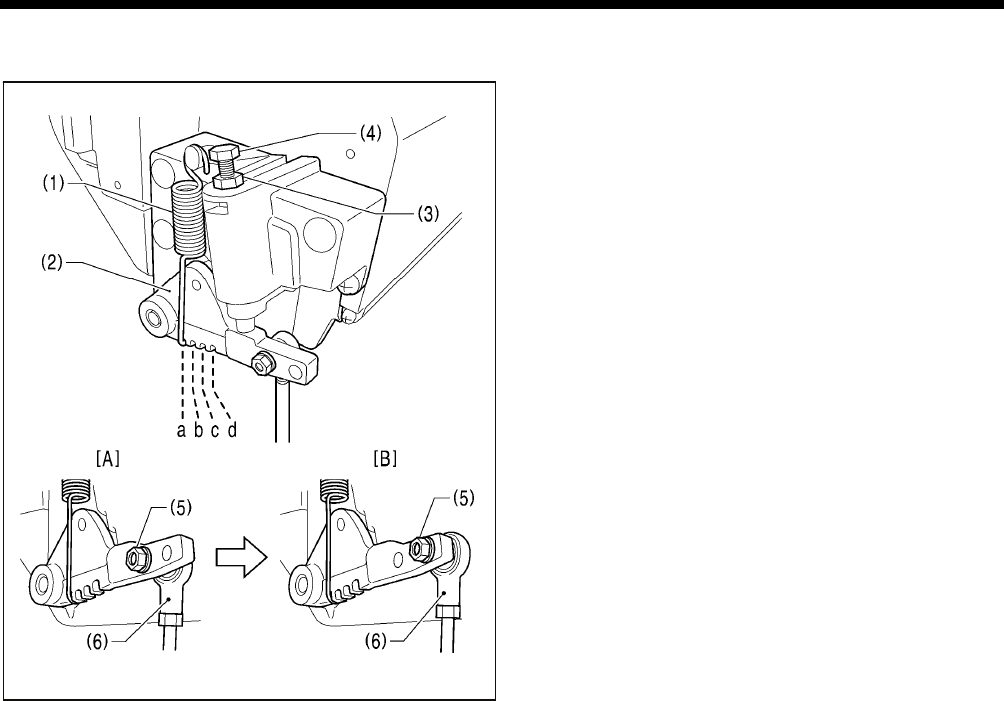
3-6. Adjusting the treadle operation
<Forward depression sensitivity adjustment>
If the machine starts running at low speed when your foot is
simply resting on the treadle, or if the treadle pressure is felt
to be too weak, adjust the position (a to c) at which the
treadle spring (1) is hooked onto the treadle lever (2).
* a is the weakest position, and it becomes gradually
stronger at b, c and d respectively.
<Backward depression sensitivity adjustment>
1. Loosen the nut (3) and turn the bolt (4).
* When the bolt (4) is tightened, the treadle operation
becomes heavier, and when it is loosened, the
operation becomes lighter.
2. Tighten the nut (3).
<Adjusting the treadle stroke>
Remove the nut (5), and then move the connecting rod joint
(6) from the position in figure A to the position in figure B.
The treadle stroke will then be increased by approximately
27 %.
At this time, the treadle forward and backward depression
sensitivity will change, so readjust if necessary.
4259M
4260M
T-8421C, 8422C, 8452C, 8722C, 8752C
4. PREPARATION BEFORE SEWING
17
4. PREPARATION BEFORE SEWING
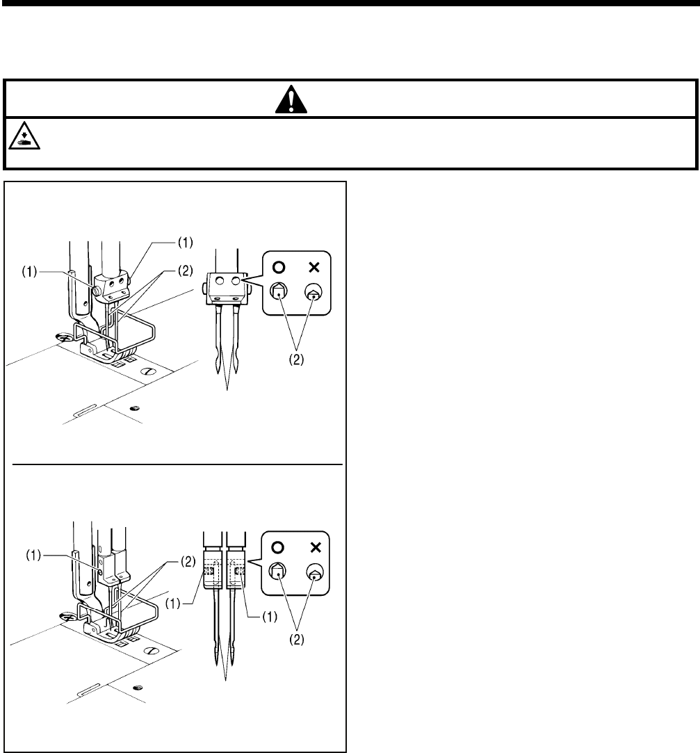
4-1. Installing the needle
CAUTION
Turn off the power switch before installing the needle.
The machine may operate if the treadle is depressed by mistake, which could result in injury.
1. Turn the machine pulley to move the needle bar to its
highest position.
2. Loosen the screws (1).
3. Insert the needle (2) straight in as far as it will go so that the
long groove is facing inward, and then securely tighten the
screws (1).
2461B
Long groove
2462B
<T-8421C, 8422C, 8722C>
<T-8452C, 8752C>
Long groove
T-8421C, 8422C, 8452C, 8722C, 8752C
4. PREPARATION BEFORE SEWING
18
4-2. Removing the bobbin
CAUTION
Turn off the power switch before removing the bobbin.
The machine may operate if the treadle is depressed by mistake, which could result in injury.
<Latch type>
1. Open the slide plates (1) by moving them to the right and
left.
2. Pull the rotary hook latches (2) upward, and them remove
the bobbins (3).
<Bobbin case type>
1. Open the slide plates (1) by moving them to the right and
left.
2. Lift up the latch (2) of the rotary hook, and then remove the
bobbin case (3).
3. Remove the bobbin.
2463B
2464B
T-8421C, 8422C, 8452C, 8722C, 8752C
4. PREPARATION BEFORE SEWING
19
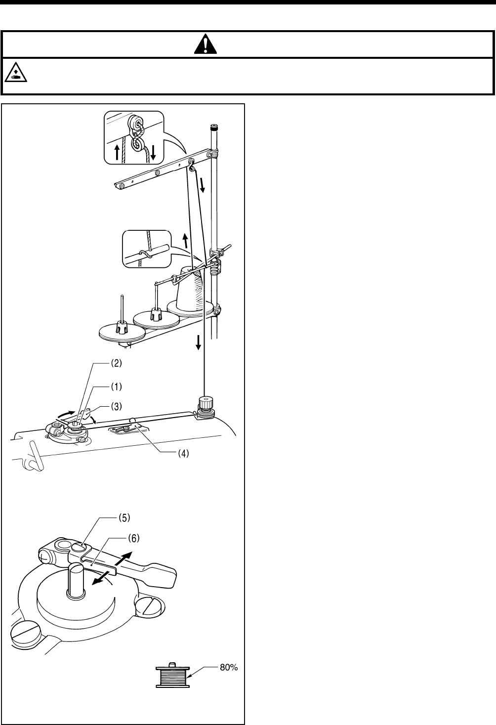
4-3. Winding the lower thread
CAUTION
Do not touch any of the moving parts or press any objects against the machine while winding the lower thread, as this
may result in personal injury or damage to the machine.
1. Turn on the power switch.
2. Place the bobbin (1) onto the bobbin winder shaft (2).
3. Wind the thread several times around the bobbin (1) in the
direction indicated by the arrow.
* Check that the thread is not loose anywhere along the
thread path.
4. Push the bobbin presser arm (3) toward the bobbin (1).
5. Raise the presser foot with the lifting lever.
6. Depress the treadle. Lower thread winding will then start.
7. Once winding of the lower thread is completed, the bobbin
presser arm (3) will return automatically.
8. After the thread has been wound on, remove the bobbin
and cut the thread with the knife (4).
* Loosen the screw (5) and move the bobbin presser (6) to
adjust the amount of thread wound onto the bobbin.
NOTE:
The amount of thread wound onto the bobbin should be
a maximum of 80 % of the bobbin capacity.
2124M2123M
Less thread
More thread
2897M
T-8421C, 8422C, 8452C, 8722C, 8752C
4. PREPARATION BEFORE SEWING
20
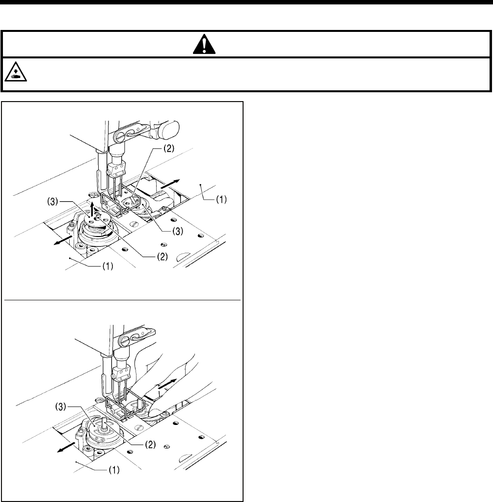
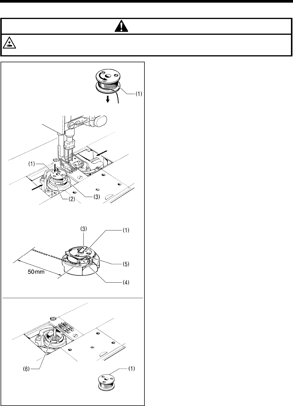
4-4. Installing the bobbin
CAUTION
Turn off the power switch before installing the bobbin.
The machine may operate if the treadle is depressed by mistake, which could result in injury.
<Latch type>
1. Insert the bobbin (1) into the rotary hook (2) so that the
winding direction is as shown in the illustration.
2. Return the rotary hook latch (3) to its original position.
3. Turn the machine pulley to rotate the rotary hook (2) until
the tension spring (4) is visible.
4. Pass the thread through slit (5) in the rotary hook and then
pass it under the thread tension spring.
5. Pull out the thread to a length of approximately 50 mm.
6. Close the slide plates.
There is an anti-spin spring (6) inside the rotary hook. The
anti-spin spring (6) prevents the bobbin from racing at times
such as during thread trimming.
Use bobbins (1) made of light alloy as specified by
BROTHER.
2898M
2465B
2900M
2466B
T-8421C, 8422C, 8452C, 8722C, 8752C
4. PREPARATION BEFORE SEWING
21
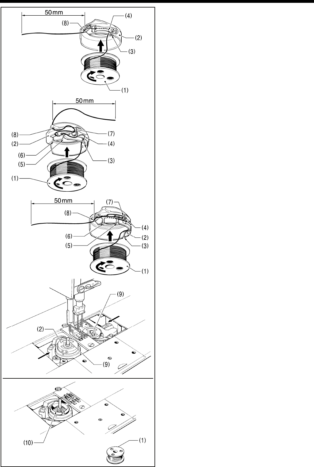
<Bobbin case type>
1. Insert the bobbin (1) into the bobbin case (2) so that the
winding direction is as shown in the illustration.
2. There are three types of cap (2) (<A>, <B> and <C>).
Thread the thread by one of the following methods in
accordance with the shape of the bobbin case (2) being
used.
<A>
1) Pass the thread through slot (3) and under the
thread tension spring (4).
2) Pass the thread through the thread hole (8) and pull
out about 50 mm.
<B> <C>
1) Pass the thread through slot (3) and under the
thread tension spring (4).
2) Pass the thread through slots (5) and (6), and then
through the spring (7).
3) Pass the thread through the thread hole (8) and pull
out about 50 mm.
3. Insert the bobbin case (2) into the rotary hook.
4. Push latch (9) of the rotary hook flat.
5. Close the slide plates.
There is an anti-spin spring (10) inside the rotary hook. The
anti-spin spring (10) prevents the bobbin from racing at
times such as during thread trimming.
Use bobbins (1) made of light alloy as specified by
BROTHER.
3126M
2902M
2467B
2468B
<A>
3127M
<B>
<C>

T-8421C, 8422C, 8452C, 8722C, 8752C
4. PREPARATION BEFORE SEWING
22
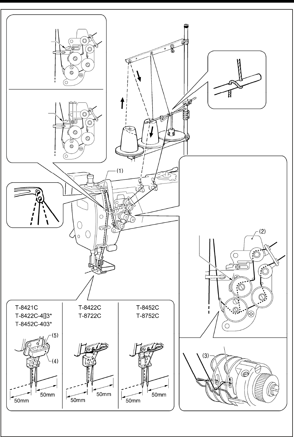
4-5. Threading the upper thread
CAUTION
Turn off the power switch before threading the upper thread.
The machine may operate if the treadle is depressed by mistake, which could result in injury.
・ Turn the machine pulley and raise the thread take-up (1) before threading the upper thread.
This will make threading easier and it will prevent the thread from coming out at the sewing start.
・ Thread the left-side thread first.
T-8421C, 8422C, 8452C, 8722C, 8752C
4. PREPARATION BEFORE SEWING
23
Specifications indicated by the * mark include arm thread guide D (4) and felt (5). When using polyester thread, install
these components and thread the thread as shown in the illustration.
Do not pass the
thread through.
<For all models except foundation
specifications and T-8452C-405>
Pass the thread
through.
<For foundation specifications
and T-8452C-405> Cente
r
(Refer to page 54
of the instruction
manual CD)
If the tension discs are opened as
follows, the thread will become easier
to thread.
<Models with thread trimmer>
Press the tension release plate (2).
<Models without thread trimmer>
Press the tension release plate (2),
or operate the lifting lever or the knee
lifter to raise the presser foot.
The thread can be passed securely
in between the tension discs.
Pass the thread on the inside of the tab (3).
2183B
T-8421C, 8422C, 8452C, 8722C, 8752C
4. PREPARATION BEFORE SEWING
24
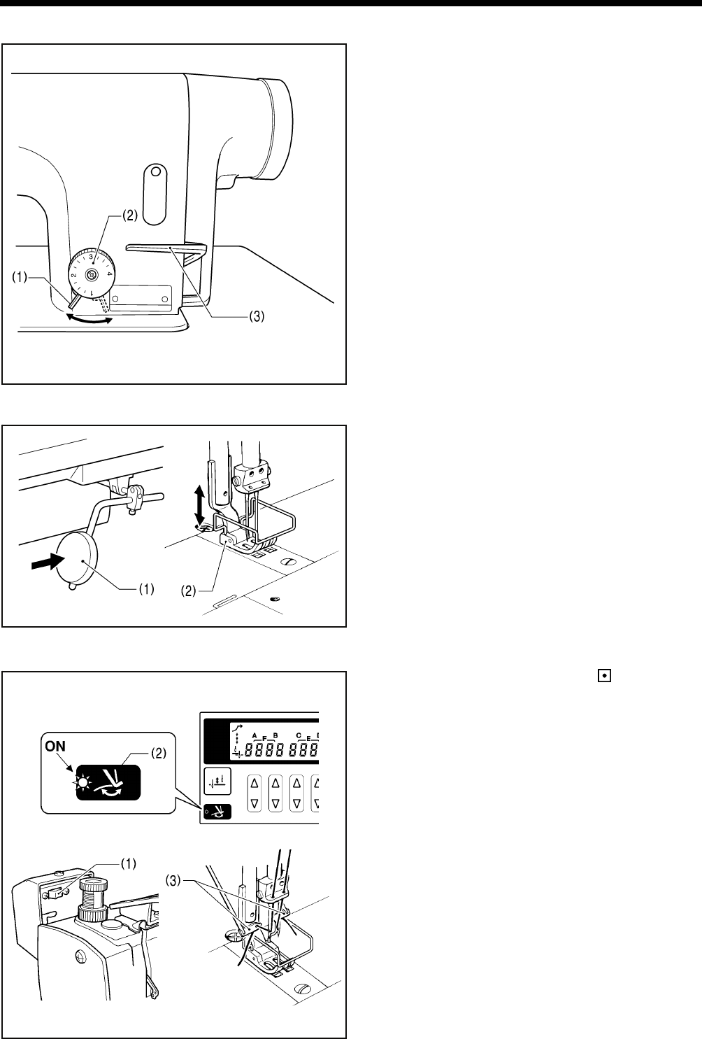
4-6. Adjusting the stitch length
1. Unlock the stitch length dial (2) by turning the dial lock lever
(1) to the right until a click is heard.
2. Turn the stitch length dial (2) clockwise or counterclockwise
so that the desired stitch length is at the uppermost position
on the dial.
The larger the number, the longer the stitch length will be.
(The numbers on the dial are for use as a guide. The
length of the finished stitches may vary depending on the
type and thickness of material being sewn. Adjust while
looking at the finished stitches.)
When turning the stitch length dial (2) from a larger
setting to a smaller setting, it will be easier to turn the dial
if the reverse lever (3) is pushed to the halfwaydown
position.
3. Turn the dial lock lever (1) firmly to the left to lock the stitch
length dial (2).
* Check that the stitch length dial (2) does not rotate.
4-7. Using the knee lifter
The presser foot (2) can be raised by pressing the knee lifter
plate (1).
4-8. Using the thread wiper (models with thread trimmer only)
1. Press the thread wiper switch (1) to the side.
2. Press the thread wiper key (2) on the operation panel so
that the indicator illuminates.
After thread trimming is carried out, the thread wiper (3) will
pull up the thread.
2907M
2184B
2906M
Locked Unlocked
2469B
2470B
T-8421C, 8422C, 8452C, 8722C, 8752C
4. PREPARATION BEFORE SEWING
25
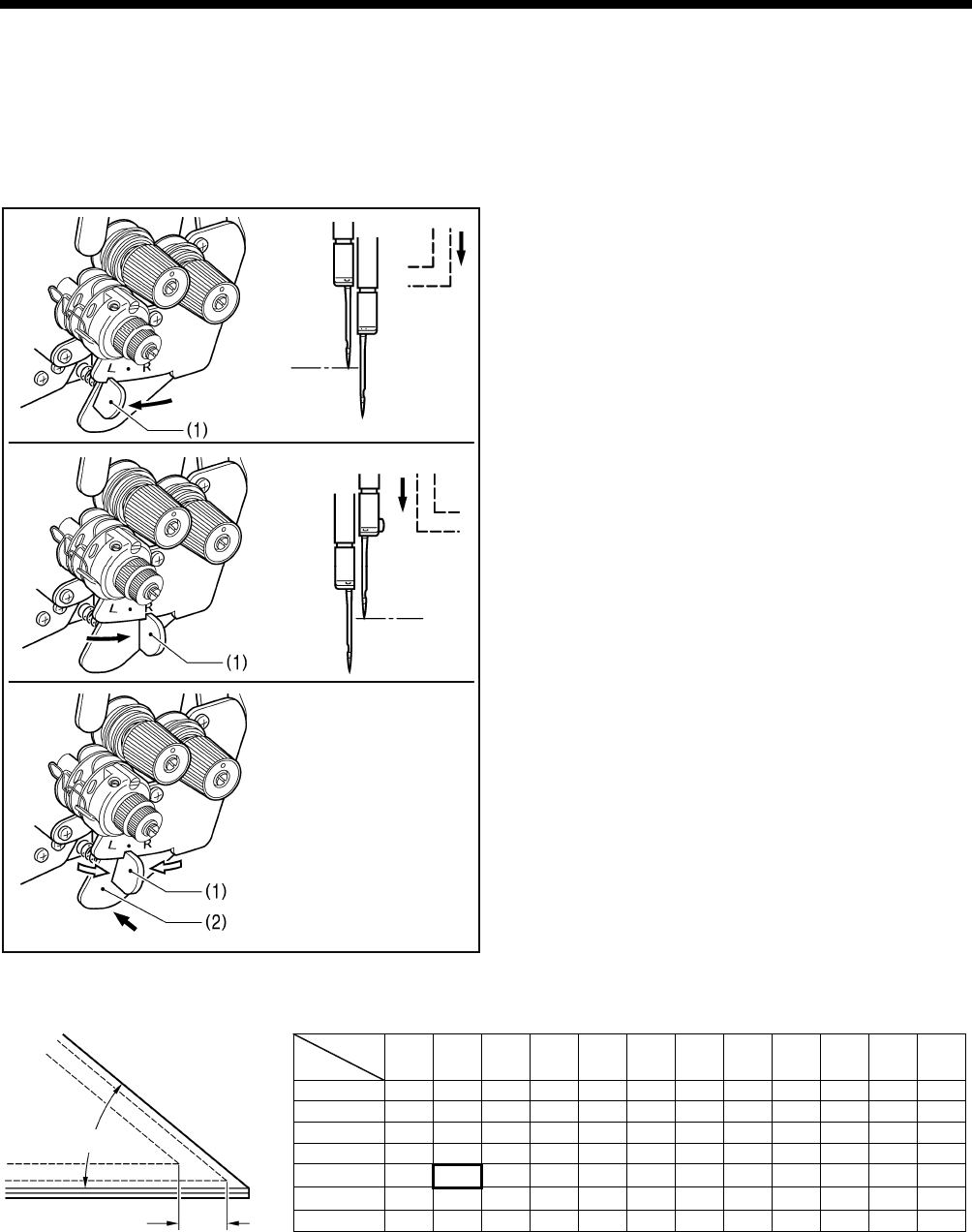
4-9. Corner sewing method (T-8452C, 8752C)
NOTE:
If using this machine in place of a single-needle machine, remove the needle which is not being used. In such cases, do not
use the procedures given below to stop the unused needle bar from moving, otherwise damage to the machine may result.
4-9-1. To stop the needle bars (right and left)
Operate the stop lever after the needle has penetrated the
material and has stopped moving.
Do not sew at speeds of over 1,000 sti/min while one of the
needle bars has been stopped.
<To stop operation of the left needle bar>
Move the stop lever (1) to the “L” position.
<To stop operation of the right needle bar>
Move the stop lever (1) to the “R” position.
<To resume twin-needle sewing>
Press the push lever (2).
The stop lever (1) will then return to its original position
automatically.
4-9-2. Number of stitches: quick-reference guide
<For 1/4” needle width>
Determine the stitch length from the chart above to make beautiful corner stitching.
The number of stitches of the outer needle varies according to the combination of sewing angle and stitch length.
[Example]
For a sewing angle of 40° and a stitch length of 2.9 mm, the number of stitches becomes 6.
3131M
30° 40° 50° 60° 70° 80° 90° 100° 110° 120° 130° 140°
2 4.6 3.8 3.2 2.7 2.2 1.8 1.5 1.1
3 4.6 3.5 3.0 2.5 2.1 1.8 1.5 1.2
4 4.4 3.4 2.8 2.3 1.9 1.6 1.3
5 4.8 3.5 2.7 2.2 1.8 1.5 1.3
6 4.0 2.9 2.3 1.9 1.5 1.3
7 3.7 2.5 2.0 1.6
8 3.0 2.2 1.7
Sewing
angle
No. o
f
Stitches
Sewing angle 40°
No. of stitches 6
3130M
3128M
3129M
Needle
stop
Push
Needle
stop
T-8421C, 8422C, 8452C, 8722C, 8752C
5. USING THE G50 OPERATION PANEL (BASIC OPERATIONS)
26
5. USING THE G50 OPERATION PANEL
(BASIC OPERATIONS)
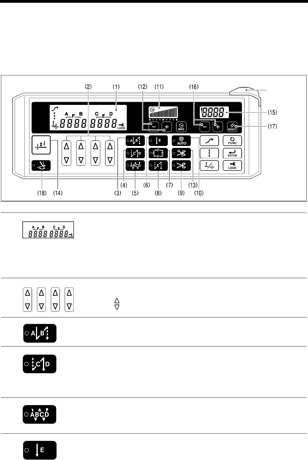
5-1. Names and functions
• The operation panel keys cannot be operated while sewing is in progress.
Select the keys and set the number of stitches before starting sewing.
• In the case of keys with indicators, the indicator illuminates when that function is operating, and the indicator switches off
when the key is pressed once more.
The power indicator illuminates when the power switch is turned on.
(1) Main display
• In start backtack display, AB illuminates and the number of stitches for A and B are
displayed.
• In end backtack display, CD illuminates and the number of stitches for C and D are
displayed.
• In continuous backtack display, ABCD illuminates and the number of stitches for A, B, C
and D are displayed.
• In fixed stitch display, E or F illuminates and the number of stitches for E or F are
displayed.
(2) Setting keys
These keys are used to set the number of backtack stitches for A, B, C and D and the
number of fixed stitches for E and F.
• When the key is pressed, the setting increases from 0 up to 99.
• When the key is pressed, the setting decreases from 99 down to 0.
(3) Start backtack key
When this key is pressed so that the indicator illuminates, the number of start backtack
stitches (0−99) in the A and B stitch number displays is sewn.
(4) End backtack key
When this key is pressed so that the indicator illuminates, the number of end backtack
stitches (0−99) in the C and D stitch number displays is sewn. When the treadle is
depressed backward, the end backtack stitches are sewn and then the thread is trimmed
automatically (models with thread trimmer).
If the treadle has not yet been depressed backward, the end backtack function can be set
to ON, the number of stitches can be changed and the function can be set back to OFF.
(5) Continuous backtack key
When this key is pressed so that the indicator illuminates, the number of backtack stitches
(0−99) in the A, B, C and D stitch number displays is sewn continuously. After the sewing
machine sews a full cycle of stitches set by A, B, C and D, the thread is trimmed
automatically (models with thread trimmer).
(6) Fixed stitch key
When this key is pressed so that the indicator illuminates, the number of stitches (0-1999)
in the E stitch number display is sewn, and then the sewing machine stops automatically.
4159M
Power indicator
2136M
4160M 2138M 2139M
4161M
4162M
4163M
4164M
T-8421C, 8422C, 8452C, 8722C, 8752C
5. USING THE G50 OPERATION PANEL (BASIC OPERATIONS)
27
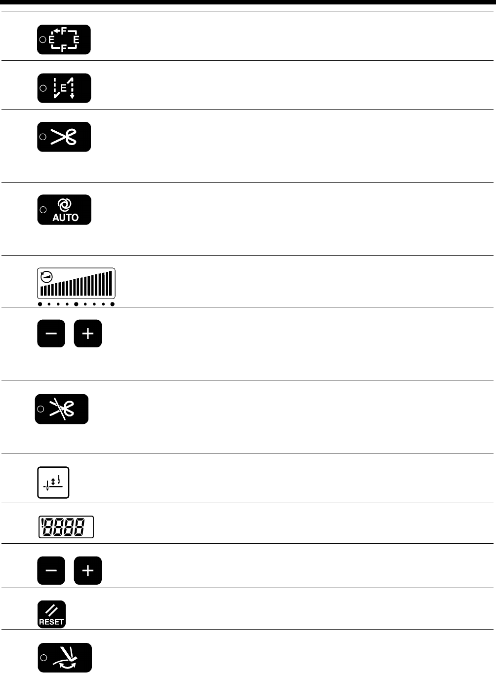
(7) Name label key
When this key is pressed so that the indicator illuminates, fixed stitch sewing of the number
of stitches (0-1999) in the E and F stitch number displays is carried out repeatedly.
4165M
(8) Pleat presser sewing key
When this key is pressed so that the indicator illuminates, the number of backtack stitches
(0-1999) in the E stitch number display can be sewn by pressing the actuator switch.
4166M
(9) Thread trimming key (models with thread trimmer only)
• This can only be set for use together with the fixed stitch key (6) or the name label key
(7).
• When this key is pressed so that the indicator illuminates, the set number of stitches
(start or end backtack stitches or fixed stitches) are sewn, and then the thread is
trimmed automatically.
(10) AUTO key
• This can only be set for use together with the continuous backtack key (5), the fixed
stitch key (6) or the name label key (7).
• When this key is pressed so that the indicator illuminates, the set number of stitches
(start or end backtack stitches, fixed stitches or thread trimming (models with thread
trimmer)) are sewn automatically simply by depressing the treadle once.
(11) Sewing speed control display
This shows the sewing speed when the treadle is depressed to the maximum amount.
• If all bars are illuminated, it indicates that the maximum speed can be set.
• If all bars are switched off, it indicates the minimum speed (250 sti/min).
(12) Sewing speed control keys
These keys let you adjust the sewing speed that is used when the treadle is depressed to
the maximum amount.
The sewing speed can also be adjusted while sewing is in progress.
• When the + key is pressed, the sewing speed becomes faster.
• When the - key is pressed, the sewing speed becomes slower.
(13) Thread trimming lock key (models with thread trimmer only)
• When this key is pressed so that the indicator illuminates, the sewing machine stops in
the needle up position without thread trimming being carried out even if the treadle is
depressed backward.
• If the indicator of the AUTO key (10) is illuminated, the sewing machine stops in the
needle up position without thread trimming being carried out after the set number of
stitches have been sewn.
(14) Half stitch key
When the sewing machine is stopped, the needle bar can be moved up and down by
pressing this key.
(15) Lower thread counter display
This shows the lower thread counter value.
The counter is reduced by “1” for every ten stitches sewn.
(16) Lower thread counter keys
These keys are used to set the initial value for the lower thread counter. (Refer to “5-6.
Using the lower thread counter” in the instruction manual CD.)
(17) RESET key
This key is used to return the lower thread counter to its initial value and to cancel warning
conditions. (Refer to “5-6. Using the lower thread counter” in the instruction manual CD.)
(18) Thread wiper key
• When this key is pressed so that the indicator illuminates, the thread wiper (-4[][]
specifications) operates. (Refer to “4-8. Using the thread wiper (models with thread
trimmer only)”.)
• When the indicator of the thread trimming lock key (13) is illuminated, the thread wiper
key (18) is disabled.
• If you press the thread trimming lock key (13) so that its indicator illuminates while the
indicator of the thread wiper key (18) is illuminated, the indicator of the thread wiper key
(18) will switch off.
4174M
4167M
4168M
4169M
4170M
4171M
4172M
2154M
4170M
4173M
T-8421C, 8422C, 8452C, 8722C, 8752C
5. USING THE G50 OPERATION PANEL (BASIC OPERATIONS)
28
5-2. Sewing start and end backtack stitches
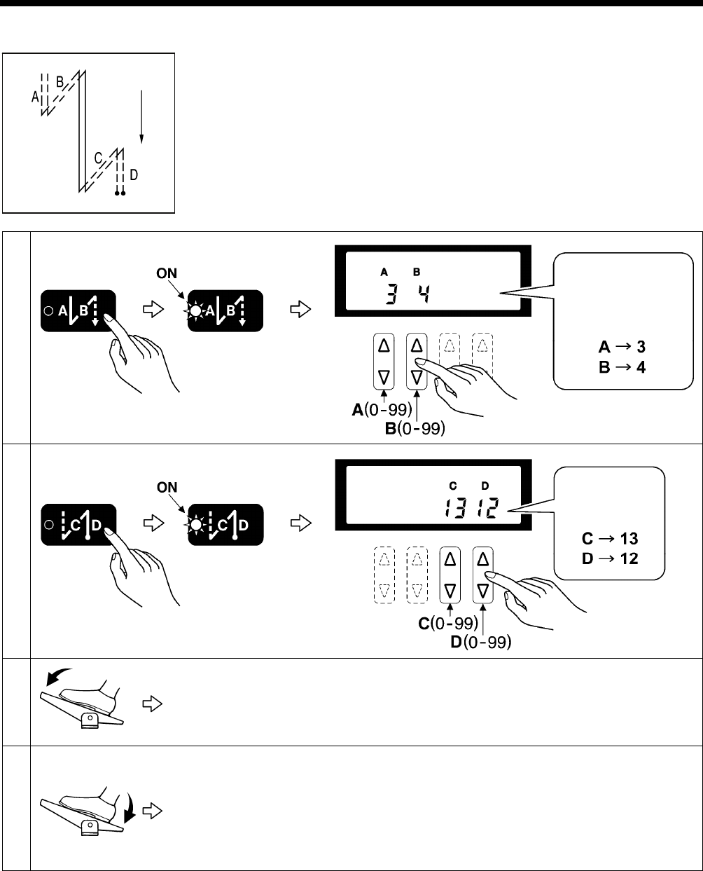
1 Setting start backtack stitches
2 Setting end backtack stitches
3
Start backtacking is carried out. After it has finished, normal sewing continues for as long as
the treadle remains depressed.
NOTE:
If the treadle is returned to the neutral position, the sewing machine will continue
operating until the set number of start backtack stitches has been sewn.
4
End backtacking is carried out. After it has finished, the thread is trimmed automatically
(models with thread trimmer) and the sewing machine stops in the needle up position.
NOTE:
• If the treadle is depressed backward before sewing of the set number of start backtack
stitches is complete, end backtacking will not be carried out.
• If the indicator of the thread trimming lock key is illuminated, the sewing machine will
stop in the needle up position without thread trimming being carried out.
2911M
4175M
For example,
3 stitches and
4 stitches
4176M
Example:
2159M
2160M
T-8421C, 8422C, 8452C, 8722C, 8752C
6. SEWING
29
6. SEWING
CAUTION
Attach all safety devices before using the sewing machine. If the machine is used without these devices attached,
injury may result.
Turn off the power switch at the following times.
The machine may operate if the treadle is depressed by mistake, which could result in injury.
y When threading the needle
y When replacing the bobbin and needle
y When not using the machine and when leaving the machine unattended
Do not touch any of the moving parts or press any objects against the machine while sewing, as this may result in
personal injury or damage to the machine.
Secure the table so that it will not move when tilting back the machine head. If the table moves, it may crush your
feet or cause other injuries.
Use both hands to hold the machine head when tilting it back or returning it to its original position. If only one hand
is used, the weight of the machine head may cause your hand to slip, and your hand may get caught.
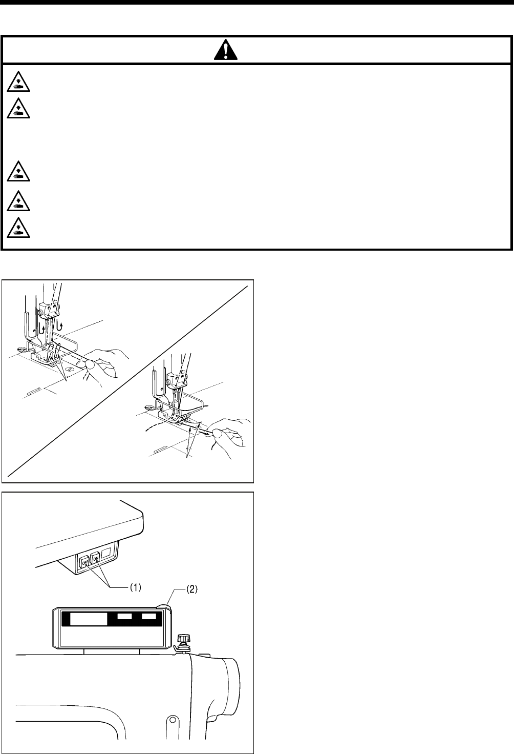
6-1. Sewing
1. While holding the two upper threads with your fingers, turn
the machine pulley by hand toward you until the lower
threads come out onto the feed dog.
2. Pull the lower threads toward you and check that they pull
out smoothly.
3. Press the ON power switch (1).
The power indicator (2) will illuminate.
4. Use the operating panel to carry out the programming
which is necessary for sewing.
(Refer to the chapter on “5. Using the operating panel”.)
5. Depress the treadle to start sewing.
2114M
2471B
2472B
Lower
thread
Lower thread
2182B
T-8421C, 8422C, 8452C, 8722C, 8752C
6. SEWING
30
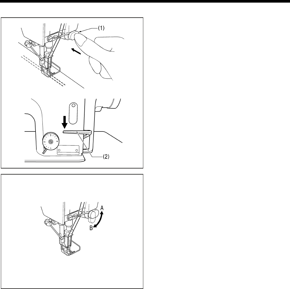
6-2. Backtacking
When the actuator switch (1) or the reverse lever (2) is
pressed during sewing, the feed direction will be reversed.
When it is released, the feed direction will return to normal.
< Actuator switch rotation function >
The actuator switch can be rotated 90 degrees as shown in
the illustration. Select the position (A or B) that is easier to
use.
2916M
2917M
2918M

MEMO
T-8421C, 8422C, 8452C, 8722C, 8752C

For cleaning, standard adjustments and more details, please refer to the instruction
manual contained in the Document CD.
Contents of the Document CD
The following documents are contained in PDF format.
・ Basic Operation Manual
・ Instruction Manual
・ Parts Book
Recommended system configuration for using the Document CD
OS: Windows® XP Service Pack 2, Windows Vista®, Windows® 7
Browser version: Microsoft® Internet Explorer 6 Service Pack 1 or higher
Screen resolution: 1024 x 768 pixeles or more
Plug in (required to access): Adobe Reader 8.0 or higher
Adobe, the Adobe logo, and Reader are either registered trademarks or trademarks of Adobe Systems Incorporated in the
United States and/ or other countries.
Windows® and Microsoft® Internet Explorer are either registered trademarks of Microsoft Corporation in the United States
and/ or other countries.
Document CD
T-8421C, 8422C, 8452C, 8722C, 8752C
SB1408-001 E
2010.05.B(1)
© 2010 Brother Industries, Ltd. All Rights Reserved.
This is the original instructions.
3168M
