Browning Integra Dhc 80 2 Owners Manual 80.2_En_100715
Integra-Dhc-80-2-Owners-Manual-803977 integra-dhc-80-2-owners-manual-803977
2015-09-10
: Browning Integra-Dhc-80-2-Owners-Manual-803977 integra-dhc-80-2-owners-manual-803977 browning pdf
Open the PDF directly: View PDF ![]() .
.
Page Count: 116 [warning: Documents this large are best viewed by clicking the View PDF Link!]
- Introduction
- Connections
- Turning On & Basic Operations
- Turning On/Off the AV Controller
- Basic Operations
- Selecting the Language Used for the Onscreen Setup Menus
- Playing the Connected Component
- Displaying Source Information
- Setting the Display Brightness
- Muting the AV Controller
- Using the Sleep Timer
- Using the Home Menu
- Changing the Input Display
- Using Headphones
- Using Activities to Start Easy Macros
- Audyssey MultEQ® XT32 Room Correction and Speaker Setup
- Listening to the Radio
- Recording
- Using the Listening Modes
- Advanced Operations
- Controlling iPod & Other Components
- Controlling iPod
- Controlling Other Components
- Preprogrammed Remote Control Codes
- Looking up for Remote Control Code
- Entering Remote Control Codes
- Remote Control Codes for Integra/ Onkyo Components Connected via RI
- Resetting Remote Mode Buttons
- Resetting the Remote Controller
- Controlling Other Components
- Activities Setup
- Learning Commands
- Using Normal Macros
- Others

AV Controller
DHC-80.2
Instruction Manual
2
En
Introduction
Important Safety Instructions
1. Read these instructions.
2. Keep these instructions.
3. Heed all warnings.
4. Follow all instructions.
5. Do not use this apparatus near water.
6. Clean only with dry cloth.
7. Do not block any ventilation openings. Install in
accordance with the manufacturer’s instructions.
8. Do not install near any heat sources such as radiators,
heat registers, stoves, or other apparatus (including
amplifiers) that produce heat.
9. Do not defeat the safety purpose of the polarized or
grounding-type plug. A polarized plug has two blades
with one wider than the other. A grounding type plug
has two blades and a third grounding prong. The wide
blade or the third prong are provided for your safety. If
the provided plug does not fit into your outlet, consult
an electrician for replacement of the obsolete outlet.
10. Protect the power cord from being walked on or
pinched particularly at plugs, convenience receptacles,
and the point where they exit from the apparatus.
11. Only use attachments/accessories specified by the
manufacturer.
12. Use only with the cart, stand,
tripod, bracket, or table speci-
fied by the manufacturer, or
sold with the apparatus. When
a cart is used, use caution
when moving the cart/appara-
tus combination to avoid
injury from tip-over.
13. Unplug this apparatus during lightning storms or when
unused for long periods of time.
14. Refer all servicing to qualified service personnel. Ser-
vicing is required when the apparatus has been dam-
aged in any way, such as power-supply cord or plug is
damaged, liquid has been spilled or objects have fallen
into the apparatus, the apparatus has been exposed to
rain or moisture, does not operate normally, or has
been dropped.
15. Damage Requiring Service
Unplug the apparatus from the wall outlet and refer
servicing to qualified service personnel under the fol-
lowing conditions:
A. When the power-supply cord or plug is damaged,
B. If liquid has been spilled, or objects have fallen
into the apparatus,
C. If the apparatus has been exposed to rain or water,
D. If the apparatus does not operate normally by fol-
lowing the operating instructions. Adjust only
those controls that are covered by the operating
instructions as an improper adjustment of other
controls may result in damage and will often
require extensive work by a qualified technician to
restore the apparatus to its normal operation,
E. If the apparatus has been dropped or damaged in
any way, and
F. When the apparatus exhibits a distinct change in
performance this indicates a need for service.
16. Object and Liquid Entry
Never push objects of any kind into the apparatus
through openings as they may touch dangerous volt-
age points or short-out parts that could result in a fire
or electric shock.
The apparatus shall not be exposed to dripping or
splashing and no objects filled with liquids, such as
vases shall be placed on the apparatus.
Don’t put candles or other burning objects on top of
this unit.
17. Batteries
Always consider the environmental issues and follow
local regulations when disposing of batteries.
18. If you install the apparatus in a built-in installation,
such as a bookcase or rack, ensure that there is ade-
quate ventilation.
Leave 20 cm (8") of free space at the top and sides and
10 cm (4") at the rear. The rear edge of the shelf or
board above the apparatus shall be set 10 cm (4")
away from the rear panel or wall, creating a flue-like
gap for warm air to escape.
WARNING:
TO REDUCE THE RISK OF FIRE OR ELECTRIC
SHOCK, DO NOT EXPOSE THIS APPARATUS TO
RAIN OR MOISTURE.
CAUTION:
TO REDUCE THE RISK OF ELECTRIC SHOCK,
DO NOT REMOVE COVER (OR BACK). NO
USER-SERVICEABLE PARTS INSIDE. REFER
SERVICING TO QUALIFIED SERVICE
PERSONNEL.
The lightning flash with arrowhead symbol, within an
equilateral triangle, is intended to alert the user to the
presence of uninsulated “dangerous voltage” within
the product’s enclosure that may be of sufficient
magnitude to constitute a risk of electric shock to
persons.
The exclamation point within an equilateral triangle is
intended to alert the user to the presence of important
operating and maintenance (servicing) instructions in
the literature accompanying the appliance.
WARNING
RISK OF ELECTRIC SHOCK
DO NOT OPEN
RISQUE DE CHOC ELECTRIQUE
NE PAS
OUVRIR
AVIS
PORTABLE CART WARNIN
G
S3125A

3
En
Precautions
1. Recording Copyright—Unless it’s for personal use
only, recording copyrighted material is illegal without
the permission of the copyright holder.
2. AC Fuse—The AC fuse inside the unit is not user-ser-
viceable. If you cannot turn on the unit, contact the
dealer from whom you purchased this unit.
3. Care—Occasionally you should dust the unit all over
with a soft cloth. For stubborn stains, use a soft cloth
dampened with a weak solution of mild detergent and
water. Dry the unit immediately afterwards with a
clean cloth. Don’t use abrasive cloths, thinners, alco-
hol, or other chemical solvents, because they may
damage the finish or remove the panel lettering.
4. Power
WARNING
BEFORE PLUGGING IN THE UNIT FOR THE
FIRST TIME, READ THE FOLLOWING SECTION
CAREFULLY.
AC outlet voltages vary from country to country.
Make sure that the voltage in your area meets the volt-
age requirements printed on the unit’s rear panel (e.g.,
AC 230 V, 50 Hz or AC 120 V, 60 Hz).
The power cord plug is used to disconnect this unit
from the AC power source. Make sure that the plug is
readily operable (easily accessible) at all times.
Pressing On/Standby to select Standby mode does
not fully shutdown the unit. If you do not intend to use
the unit for an extended period, remove the power cord
from the AC outlet.
5. Preventing Hearing Loss
Caution
Excessive sound pressure from earphones and head-
phones can cause hearing loss.
6. Batteries and Heat Exposure
Warning
Batteries (battery pack or batteries installed) shall not
be exposed to excessive heat as sunshine, fire or the
like.
7. Never Touch this Unit with Wet Hands—Never han-
dle this unit or its power cord while your hands are
wet or damp. If water or any other liquid gets inside
this unit, have it checked by the dealer from whom
you purchased this unit.
8. Handling Notes
• If you need to transport this unit, use the original
packaging to pack it how it was when you originally
bought it.
• Do not leave rubber or plastic items on this unit for
a long time, because they may leave marks on the
case.
• This unit’s top and rear panels may get warm after
prolonged use. This is normal.
• If you do not use this unit for a long time, it may not
work properly the next time you turn it on, so be
sure to use it occasionally.
For U.S. models
FCC Information for User
CAUTION:
The user changes or modifications not expressly approved
by the party responsible for compliance could void the
user’s authority to operate the equipment.
NOTE:
This equipment has been tested and found to comply with
the limits for a Class B digital device, pursuant to Part 15
of the FCC Rules. These limits are designed to provide
reasonable protection against harmful interference in a
residential installation.
This equipment generates, uses and can radiate radio fre-
quency energy and, if not installed and used in accordance
with the instructions, may cause harmful interference to
radio communications. However, there is no guarantee
that interference will not occur in a particular installation.
If this equipment does cause harmful interference to radio
or television reception, which can be determined by turn-
ing the equipment off and on, the user is encouraged to try
to correct the interference by one or more of the following
measures:
• Reorient or relocate the receiving antenna.
• Increase the separation between the equipment and
receiver.
• Connect the equipment into an outlet on a circuit differ-
ent from that to which the receiver is connected.
• Consult the dealer from whom you purchased this unit or
an experienced radio/TV technician for help.
For Canadian Models
NOTE: THIS CLASS B DIGITAL APPARATUS COM-
PLIES WITH CANADIAN ICES-003.
For models having a power cord with a polarized plug:
CAUTION: TO PREVENT ELECTRIC SHOCK,
MATCH WIDE BLADE OF PLUG TO WIDE SLOT,
FULLY INSERT.
Modèle pour les Canadien
REMARQUE: CET APPAREIL NUMÉRIQUE DE
LA CLASSE B EST CONFORME À LA NORME
NMB-003 DU CANADA.
Sur les modèles dont la fiche est polarisée:
ATTENTION: POUR ÉVITER LES CHOCS ÉLEC-
TRIQUES, INTRODUIRE LA LAME LA PLUS LARGE
DE LA FICHE DANS LA BORNE CORRESPON-
DANTE DE LA PRISE ET POUSSER JUSQU’AU
FOND.
4
En
Thank you for purchasing an Integra AV controller.
Please read this manual thoroughly before making con-
nections and plugging in the unit.
Following the instructions in this manual will enable you
to obtain optimum performance and listening enjoyment
from your new AV controller.
Please retain this manual for future reference.
Supplied Accessories
Make sure you have the following accessories:
*In catalogs and on packaging, the letter at the end of the prod-
uct name indicates the color. Specifications and operations are
the same regardless of color.
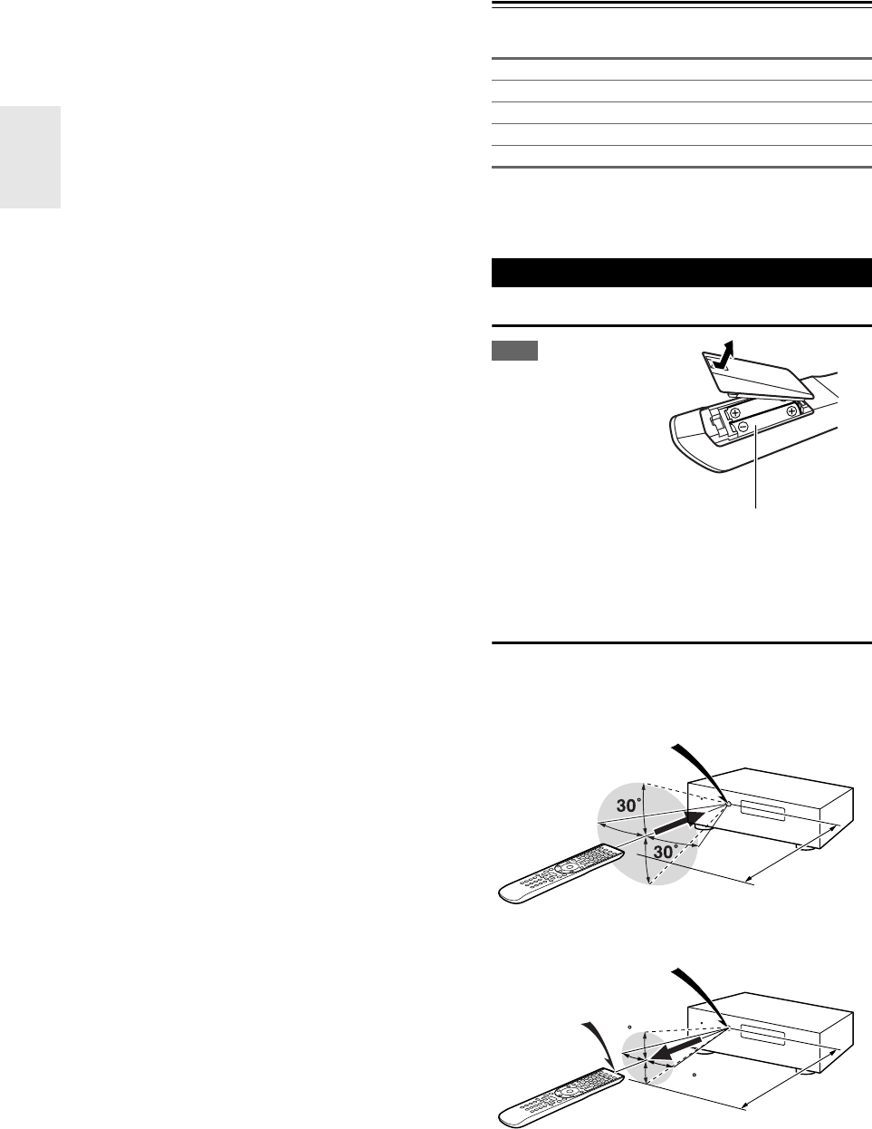
Installing the Batteries
Note
• If the remote controller
doesn’t work reliably, try
replacing the batteries.
• Don’t mix new and old
batteries or different
types of batteries.
• If you intend not to use
the remote controller for
a long time, remove the
batteries to prevent dam-
age from leakage or corrosion.
• Remove expired batteries as soon as possible to prevent damage
from leakage or corrosion.
Aiming the Remote Controller
To use the remote controller, point it at the AV controller’s
remote control sensor, as shown below.
Transmission
Received
Indoor FM antenna (➔22)
AM loop antenna (➔22)
Power cord (➔22)
Speaker setup microphone (➔30)
Remote controller and two batteries (AA/R6)
Using the Remote Controller
Batteries (AA/R6)
Remote control sensor
AV controller
Approx. 16 ft. (5 m)
15
15
Transmitter
AV controller
Approx. 16 ft. (5 m)
Incoming sensor

5
En
Contents
Important Safety Instructions ......................................... 2
Precautions....................................................................... 3
Supplied Accessories...................................................... 4
Using the Remote Controller .......................................... 4
Features ............................................................................ 6
Front & Rear Panels......................................................... 8
Front Panel..................................................................... 8
Display............................................................................ 9
Rear Panel ................................................................... 10
Remote Controller.......................................................... 11
Controlling the AV Controller........................................ 11
About Home Theater...................................................... 12
Enjoying Home Theater................................................ 12
Connecting the AV Controller....................................... 13
Connecting Your Speakers .......................................... 13
About AV Connections ................................................. 18
Connecting Your Components with HDMI.................... 19
Connecting Your Components ..................................... 20
Connecting Integra/Onkyo u Components ................ 21
Connecting Antenna..................................................... 22
Connecting the Power Cord ......................................... 22
Which Connections Should I Use?............................... 23
Turning On/Off the AV Controller ................................. 25
Turning On ................................................................... 25
Turning Off ................................................................... 25
Basic Operations............................................................ 26
Selecting the Language Used for
the Onscreen Setup Menus ....................................... 26
Playing the Connected Component.............................. 26
Displaying Source Information ..................................... 26
Setting the Display Brightness ..................................... 26
Muting the AV Controller .............................................. 27
Using the Sleep Timer.................................................. 27
Using the Home Menu.................................................. 27
Changing the Input Display .......................................... 28
Using Headphones....................................................... 28
Using Activities to Start Easy Macros........................... 28
Audyssey MultEQ®XT32
Room Correction and Speaker Setup ........................ 29
Listening to the Radio ................................................... 32
Using the Tuner............................................................ 32
Presetting FM/AM Stations........................................... 33
Listening to SIRIUS Satellite Radio®
(North American models)........................................... 33
Using RDS (Australian models).................................... 39
Recording ....................................................................... 41
Using the Listening Modes ........................................... 42
Selecting Listening Modes ........................................... 42
About Listening Modes................................................. 43
Advanced Setup ............................................................. 49
On-screen Setup Menus...............................................49
Common Procedures in Setup Menu ........................... 49
Input/Output Assign ...................................................... 50
Speaker Setup.............................................................. 54
Audio Adjust ................................................................. 57
Source Setup................................................................ 59
Listening Mode Preset.................................................. 64
Miscellaneous ............................................................... 64
Hardware Setup............................................................ 65
Lock Setup....................................................................68
Using the Audio Settings .............................................. 68
NET/USB.......................................................................... 71
About NET ....................................................................71
Connecting the AV Controller ....................................... 71
Listening to Internet Radio............................................ 72
Playing Music Files on a Server ................................... 73
Remote Playback from
Media Server/Personal Computer..............................76
Network Settings .......................................................... 77
About USB.................................................................... 79
Multi Zone .......................................................................81
Connecting Zone 2 .......................................................81
Connecting Zone 3 .......................................................82
Setting the Multi Zone...................................................82
Using Zone 2/3 ............................................................. 83
Using the 12V Triggers .................................................85
Using the Remote Controller in Zone 2/3 and
Multiroom Control Kits................................................ 86
Controlling iPod .............................................................87
Connecting the iPod Directly to the USB Port .............. 87
Connecting an Onkyo Dock.......................................... 88
Using the Onkyo Dock.................................................. 89
Controlling Your iPod.................................................... 90
Controlling Other Components.....................................92
Preprogrammed Remote Control Codes ...................... 92
Looking up for Remote Control Code ...........................92
Entering Remote Control Codes...................................94
Remote Control Codes for
Integra/Onkyo Components Connected via u......... 94
Resetting Remote Mode Buttons.................................. 95
Resetting the Remote Controller .................................. 95
Controlling Other Components ..................................... 95
Activities Setup ............................................................. 97
Learning Commands .................................................... 98
Using Normal Macros ................................................... 99
Troubleshooting ...........................................................100
Specifications ...............................................................105
About HDMI...................................................................106
Using an RIHD-compatible TV, Player, or Recorder
...107
Firmware Update .......................................................... 109
Updating the Firmware via Network ........................... 109
Updating the Firmware via USB ................................. 111
Video Resolution Chart................................................ 113
Introduction
Connections
Turning On & Basic Operations
Advanced Operations
Controlling iPod & Other Components
Others
To reset the AV controller to its factory defaults, turn
it on and, while holding down VCR/DVR, press
On/Standby (➔100).
6
En
Features
Processing
• THX Ultra2 Plus*1 Certified
• HQV-Reon-VX Video Processing with 1080p Video
Upscaling of All Video Sources via HDMI
• HDMI (Ver.1.4a with Audio Return Channel, 3D), Deep
Color, x.v.Color*2, Lip Sync, DTS*3-HD Master Audio,
DTS-HD High Resolution Audio, Dolby TrueHD*4,
Dolby Digital Plus, DSD and Multi-CH PCM
• Dolby Pro Logic IIz*4 – New Surround Format
(front-high)
• Audyssey DSX™*5 for New Surround Channels
(front-wide/front-high)
• 4 DSP Modes for Gaming; Rock/Sports/Action/RPG
• Non-Scaling Configuration
•A-Form Listening Mode Memory
• Direct Mode
• Music Optimizer*6 for Compressed Digital Music files
• High-Performance Burr-Brown 192 kHz/32-Bit DACs
• Three TI (Aureus) 32-bit Processing DSP
• Jitter Cleaning Circuit Technology
• Neural Surround Decoding*7
• DSD Direct for Super Audio CD
Connections
• Balanced XLR stereo input
• Balanced XLR 9.2-channel preouts, with front bi-amp-
ing capability
• 8 HDMI*8 Inputs (1 on front panel) and 2 Outputs
• Onkyo p for System Control
• 7 Digital Inputs (4 Optical/3 Coaxial)
• Component Video Switching (3 Inputs/1 Output)
• Universal Port for the Optional Dock for iPod*9/HD
Radio™*10 tuner module (North American mod-
els)/DAB+ tuner module (Australian models)
• 2 Independent Subwoofer Pre Outs
• Zone 2 and 3 Preouts
• Internet Radio* Connectivity (SIRIUS Internet
Radio*11/vTuner/Pandora/Rhapsody*12/Slacker/Medi-
afly/Napster)
*Services available may vary depending on the region.
• Network Capability for Streaming Audio Files
• 2 USB Inputs* (Front/Rear) for Memory Devices and
iPod®/iPhone® models (Enables Display of Album Art-
work)
*Only front-panel USB input is compatible with iPod/iPhone.
• Analog RGB Video Input (D-sub 15) for PC
Miscellaneous
•(North American models) 40 SIRIUS*11/FM/AM Pre-
sets
•(Australian models) 40 FM/AM Presets
•Dolby Volume
*4
• Audyssey MultEQ®XT32*5 to Correct Room Acoustic
Problems
• Audyssey Dynamic EQ®*5 for Loudness Correction
• Audyssey Dynamic Volume®*5 to Maintain Optimal
Listening Level and Dynamic Range
• Crossover Adjustment
(40/45/50/55/60/70/80/90/100/110/120/130/150/200 Hz)
• A/V Sync Control Function (up to 250 ms)
• Auto Power-down Function
• Bi-Directional Preprogrammed (with onscreen display
setup) RI-Compatible Learning Remote with 4 Activities
and Mode-Key LEDs
• ISF (Imaging Science Foundation) Video Calibration
•VLSC
*13 (Vector Linear Shaping Circuitry) for All
Channels
*1
THX and the THX logo are trademarks of THX Ltd. which
may be registered in some jurisdictions. All rights reserved.
*2 “x.v.Color” is a trademark of Sony Corporation.
*3
Manufactured under license under U.S. Patent #'s: 5,451,942;
5,956,674; 5,974,380; 5,978,762; 6,226,616; 6,487,535;
7,212,872; 7,333,929; 7,392,195; 7,272,567 & other U.S. and
worldwide patents issued & pending. DTS and the Symbol are
registered trademarks, & DTS-HD, DTS-HD Master Audio,
and the DTS logos are trademarks of DTS, Inc. Product
includes software.
© DTS, Inc. All Rights Reserved.
*4
Manufactured under license from Dolby Laboratories.
“Dolby”, “Pro Logic”, “Surround EX” and the double-D sym-
bol are trademarks of Dolby Laboratories.
*5
Manufactured under license from Audyssey Laboratories™.
U.S. and foreign patents pending. Audyssey MultEQ®XT32,
Audyssey DSX™, Audyssey Dynamic Volume® and
Audyssey Dynamic EQ® are registered trademarks and trade-
marks of Audyssey Laboratories.
*6 Music Optimizer™ is a trademark of Onkyo Corporation.
*7
Manufactured under license from DTS Licensing Limited.
DTS and the Symbol are registered trademarks, & DTS Neu-
ral Surround and the DTS logos are trademark of DTS, Inc.
Product includes software. © DTS, Inc. All Rights Reserved.
7
En
*8
“HDMI, the HDMI Logo, and High-Definition Multimedia
Interface are trademarks or registered trademarks of HDMI
Licensing LLC in the United States and other countries.”
*9
iPhone, iPod, iPod classic, iPod nano, iPod shuffle, and iPod
touch are trademarks of Apple Inc., registered in the U.S. and
other countries.
“Made for iPod” and “Made for iPhone” mean that an elec-
tronic accessory has been designed to connect specifically to
iPod or iPhone, respectively, and has been certified by the
developer to meet Apple performance standards. Apple is not
responsible for the operation of this device or its compliance
with safety and regulatory standards.
*10
HD Radio™ and the HD Radio Ready logo are proprietary
trademarks of iBiquity Digital Corporation.
To receive HD Radio broadcasts, you must install an Onkyo
UP-HT1 HD Radio tuner module (sold separately).
*11
SIRIUS, XM and all related marks and logos are trademarks
of Sirius XM Radio Inc. and its subsidiaries. All rights
reserved. Service not available in Alaska and Hawaii.
*12 Rhapsody and the Rhapsody logo are registered trademarks of
RealNetworks, Inc.
*13
VLSC™ is a trademark of Onkyo Corporation.
*“Xantech” is a registered trademark of Xantech Corporation.
*“Niles” is a registered trademark of Niles Audio Corporation.
*“DLNA®, the DLNA Logo and DLNA CERTIFIED™ are
trademarks, service marks, or certification marks of the Digi-
tal Living Network Alliance.”
*Re-Equalization and the “Re-EQ” logo are trademarks of
THX Ltd.
*This item incorporates copy protection technology that is pro-
tected by U.S. patents and other intellectual property rights of
Rovi Corporation. Reverse engineering and disassembly are
prohibited.
*Windows and the Windows logo are trademarks of the
Microsoft group of companies.
THX Ultra2 Plus
Before any home theater component can be THX Ultra2
Plus certified, it must pass a rigorous series of quality and
performance tests. Only then can a product feature the
THX Ultra2 Plus logo, which is your guarantee that the
Home Theater products you purchase will give you
superb performance for many years to come. THX Ultra2
Plus requirements define hundreds of parameters, includ-
ing power amplifier performance, and pre-amplifier per-
formance and operation for both digital and analog
domains. THX Ultra2 Plus receivers also feature propri-
etary THX technologies (e.g., THX Mode) which accu-
rately translate movie soundtracks for home theater
playback.
8
En
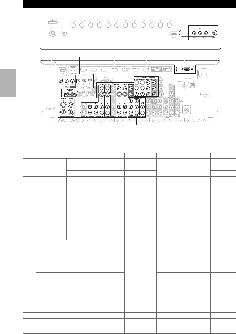
Front & Rear Panels
The actual front panel has various logos printed on it. They are not shown here for clarity.
The page numbers in parentheses show where you can find the main explanation for each item.
aOn/Standby button (➔25)
bStandby indicator (➔25)
cZone 2 indicator (➔83)
dZone 3 indicator (➔83)
eRemote control sensor/transmitter (➔4)
fMonitor Out button (➔50)
gTone and –/+ buttons (➔68, 84)
hDisplay (➔9)
iMovie/TV button (➔42)
jMusic button (➔42)
kGame button (➔42)
lDimmer button (North American models) (➔26)
mMemory button (➔33)
nTuning Mode button (➔32)
oDisplay button (➔26)
pSetup button (➔49)
qTuning, Preset (➔32 to 33), arrow and Enter
buttons
rReturn button
sMaster Volume control (➔26)
tZone 2 and Off buttons (➔83)
uZone 3 and Off buttons (➔83)
vPhones jack (➔28)
wZone Level buttons (➔84)
xSetup Mic jack (➔30)
Front Panel
C
a
yA
B
bcdefhgijklmn op
vtu x z
rsq
w
North American models
Australian models
9
En
yInput selector buttons (BD/DVD, VCR/DVR,
CBL/SAT, Game, PC, AUX, Tape, Tuner,
TV/CD, Phono, Port and NET/USB) (➔26)
zUSB port (➔79, 87)
AAUX Input HDMI jack (➔19)
BAUX Input jacks (Video, Audio L/R and Digital)
(➔20)
CRT/PTY/TP button (Australian models) (➔39)
For detailed information, see the pages in parentheses.
aSpeaker/channel indicators
bListening mode and format indicators (➔42, 69)
cNETWORK indicator (➔72, 73, 77)
dTuning indicators
RDS indicator (Australian models) (➔39)
AUTO indicator (➔32)
TUNED indicator (➔32)
FM STEREO indicator (➔32)
eSLEEP indicator (➔27)
fBi AMP indicator (➔54)
gHeadphone indicator (➔28)
hAudyssey indicator (➔29, 56)
Dynamic EQ indicator (➔59)
- (Dolby) Vol indicator (➔58)
Dynamic Vol indicator (➔60)
iMessage area
jUSB indicator (➔79, 87)
kVolume level (➔26)
lMUTING indicator (➔27)
mAudio input indicators
Display
bda e
fgh ijkl
m
c
10
En
North American models
aUNIVERSAL PORT jack
bIR IN (A/B) and OUT jacks
cDIGITAL IN COAXIAL and OPTICAL jacks
dUSB port
eETHERNET port
fu REMOTE CONTROL jack
gRS232 terminal
Terminal for control.
hHDMI IN and HDMI output (HDMI OUT MAIN and
HDMI OUT SUB) jacks
iMONITOR OUT V and S jacks
jCOMPONENT VIDEO IN and MONITOR OUT
jacks
kCOMPONENT VIDEO ZONE 2 OUT jacks
lZONE 2 OUT V jack
mPC IN port
nFM ANTENNA jack and AM ANTENNA terminal
oAC INLET
pGND screw
qINPUT jacks (BALANCE L/R)
r12V TRIGGER OUT (A/B/C) jacks
sComposite video, S-Video and analog audio jacks
(BD/DVD IN, VCR/DVR IN and OUT, CBL/SAT IN,
GAME IN, PC IN, TAPE IN and OUT, TV/CD IN
and PHONO IN)
tMULTI CH input jacks
(FRONT L/R, CENTER, SURR L/R,
SURR BACK L/R and SUBWOOFER)
uPRE OUT jacks
(FRONT L/R, CENTER, SURR L/R,
SURR BACK L/R, FRONT HIGH/WIDE L/R,
SW1, SW2, ZONE 2 L/R/SUBWOOFER and
ZONE 3 L/R/SUBWOOFER)
vSIRIUS antenna jack (North American models)
wPRE OUT jacks
(FRONT L/R, CENTER, SURR L/R,
SURR BACK L/R, FRONT HIGH/WIDE L/R,
SUBWOOFER 1 and SUBWOOFER 2)
Rear Panel
ad fg h ji lk nm o
pst
u
e
qr vw
bc
See “Connecting the AV Controller” for connection
information (➔13 to 24).
11
En
Remote Controller
For detailed information, see the pages in parentheses.
aStandby button (➔25)
bOn button (➔25)
cActivities buttons (All Off, My Movie, My TV and
My Music) (➔28, 99)
dRemote Mode/Input Selector buttons (BD/DVD,
VCR/DVR, CBL/SAT, Game, PC, AUX, Tape,
Tuner, TV/CD, Phono, Port and NET/USB)
(➔26)
eArrow q/w/e/r and Enter buttons
fSetup button (➔49)
gListening Mode buttons (Movie/TV, Music,
Game and THX) (➔42)
hDimmer button (➔26)
iDisplay button (➔26)
jMuting button (➔27)
kVOL q/w button (➔26)
lReturn button
mHome button (➔27)
nSleep button (➔27)
■Controlling the tuner
To control the AV controller’s tuner, press Tuner (or
Receiver).
You can select AM or FM by pressing Tuner repeatedly.
aArrow q/w buttons (➔32, 35)
bD.TUN button (Tuner remote mode only) (➔32,
35)
cCH +/– button (➔33, 36)
dNumber buttons (➔32, 35)
*1 When you want to change the remote controller mode without
changing the current input source, press Mode and within
about 8 seconds, press Remote Mode. Then, with the AV
controller’s remote controller, you can control the component
corresponding to the button you pressed.
*2 SP Layout is not used for this model.
*3 These buttons can be used when not in Receiver mode, and
when a Remote Mode other than Receiver mode is selected.
(Pressing Home switches to Receiver mode.)
*4 Video functions as a short cut of Video section of Home
menu (➔27).
Controlling the AV Controller
i
j*3
*4
c
l
n
h
d
b
e
f
g
a
d
c
b
a
*1
*2
k*3
m*3
To control the AV controller, press Receiver to select
Receiver mode.
You can also use the remote controller to control
Integra/Onkyo Blu-ray Disc/DVD player, CD player
and other components.
See “Entering Remote Control Codes” for more
details (➔94).
12
En
About Home Theater
Thanks to the AV controller’s superb capabilities, you can enjoy surround sound with a real sense of movement in your
own home—just like being in a movie theater or concert hall. With Blu-ray Discs or DVDs, you can enjoy DTS and
Dolby Digital. With analog or digital TV, you can enjoy Dolby Pro Logic IIx, DTS Neo:6, or Onkyo’s original DSP lis-
tening modes.
You can also enjoy THX Surround EX (THX-certified THX speaker system recommended).
Enjoying Home Theater
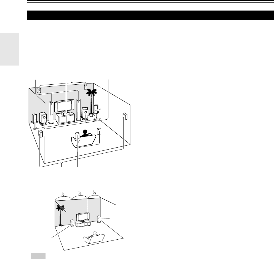
abFront speakers (Left and Right)
These output the overall sound. Their role in a home theater is to pro-
vide a solid anchor for the sound image. They should be positioned
facing the listener at about ear level, and equidistant from the TV.
Angle them inward so as to create a triangle, with the listener at the
apex.
cCenter speaker
This speaker enhances the front speakers, making sound movements
distinct and providing a full sound image. In movies it’s used mainly
for dialog. Position it close to your TV facing forward at about ear
level, or at the same height as the front speakers.
deSurround speakers (Left and Right)
These speakers are used for precise sound positioning and to add real-
istic ambience. Position them at the sides of the listener, or slightly
behind, about 2 to 3 feet (60 to 100 cm) above ear level. Ideally they
should be equidistant from the listener.
fSubwoofer(s)
The subwoofer handles the bass sounds of the LFE (Low-Frequency
Effects) channel. The volume and quality of the bass output from your
subwoofer will depend on its position, the shape of your listening
room, and your listening position. In general, a good bass sound can be
obtained by installing the subwoofer in a front corner, or at one-third
the width of the wall, as shown.
ghSurround back speakers (Left and Right)
These speakers are necessary to enjoy Dolby Digital EX, DTS-ES
Matrix, DTS-ES Discrete, THX Surround EX, etc. They enhance the
realism of surround sound and improve sound localization behind the
listener. Position them behind the listener about 2 to 3 feet (60 to
100 cm) above ear level.
ijFront high speakers (Left and Right)
These speakers are necessary to enjoy Dolby Pro Logic IIz Height, and
Audyssey DSX™. They significantly enhance the spatial experience.
Position them at least 3.3 feet (100 cm) above the front speakers (pref-
erably as high as possible) and at an angle slightly wider than the front
speakers.
klFront wide speakers (Left and Right)
These speakers are necessary to enjoy Audyssey DSX. They signifi-
cantly enhance the spatial experience. Position them well outside of the
front speakers. See also
http://www.audyssey.com/technology/dsx.html
about optimum speaker placement for Audyssey DSX.
ij
gh
kl
cb
af
de
Corner
position
1/3 of wall
position
Tip
• To find the best position for your subwoofer, while
playing a movie or some music with good bass,
experiment by placing your subwoofer at various
positions within the room, and choose the one that
provides the most satisfying results.
13
En
Connections
Connecting the AV Controller
The AV controller is designed to be used with a separate multichannel power amplifier. You connect the AV controller’s
PRE OUT jacks to the amplifier’s inputs, and connect your speakers to the amplifier’s speakers terminals. Speaker set-
tings such as crossover frequency and distance are set on the AV controller.
Speaker Configuration
The following table indicates the channels you should use depending on the number of speakers that you have.
For 9.2-channel surround-sound playback, you need 9 speakers and 2 powered subwoofers.
*1 If you’re using only one surround back speaker, connect it to the SURR BACK L output.
*2 If you use the front high and wide speakers at the same time, you need to set the “Front High + Front Wide” setting to “Yes ”
(➔54).
No matter how many speakers you use, 2 powered subwoofers are recommended for a really powerful and solid bass.
To get the best from your surround sound system, you need to set the speaker settings. You can do this automatically
(➔29) or manually (➔54).
Connecting a Power Amplifier with RCA Inputs
You can connect the AV controller to a multichannel power amplifier with RCA input jacks by using a multichannel RCA
audio cable or several stereo RCA audio cables.
See your multichannel power amplifier’s instruction manual for more information on connecting speakers.
Connecting Your Speakers
Number of speakers 2 3 45677788999
Front speakers ✔✔✔✔✔✔✔✔✔✔✔✔✔
Center speaker ✔ ✔✔✔✔✔✔✔✔✔✔
Surround speakers ✔✔✔✔✔✔✔✔✔✔✔
Surround back speaker*1 ✔✔✔
Surround back speakers ✔✔✔
Front high speakers ✔✔✔✔
Front wide speakers*2 ✔✔✔✔
SPEAKER IMPEDANCE
4 OHMS MIN. PER EACH
SPEAKER TERMINAL
AC INLET SEVEN CHANNEL AMPLIFIER
MODEL NO. RDA-7.1
INPUT
SELECT
FUSE
SURROUND BACK
RIGHT
SURROUND
RIGHT
12V TRIGGER
IN OUT
SURROUND
LEFTCENTER FRONT
LEFT
SURROUND BACK
LEFT
FRONT
INPUT
SELECT
INPUT
SELECT
INPUT
SELECT
INPUT
SELECT
INPUT
SELECT
INPUT
SELECT
OUTPUT OUTPUT OUTPUT OUTPUT OUTPUT OUTPUT OUTPUT
FRONT HIGH/
FRONT WIDE
LEFT
INPUT
SELECT
OUTPUT
FRONT HIGH/
FRONT WIDE
RIGHT
INPUT
SELECT
OUTPUT
RIGHT
Front high/
Front wide
right speaker*1
Multichannel
power amplifier
Center
speaker
Front left
speaker
Surround
left
speaker
Surround
right
speaker
Surround
back/Front
wide right
speaker*2
Front right
speaker
Surround
back/Front
wide left
speaker*2
Front high/
Front wide
left speaker*1
AV controller
14
En
Note
*1 Specify crossover frequency for the channel that you want to output in “Speaker Configuration” (➔54).
*2 If you use the front high and wide speakers at the same time, you need to set the “Front High + Front Wide” setting to “Yes ”
(➔54).
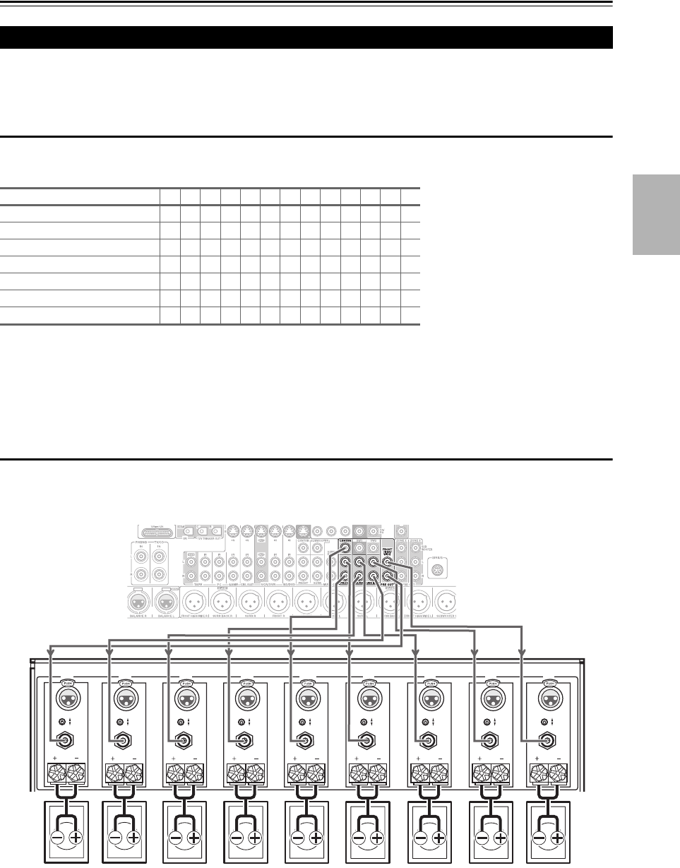
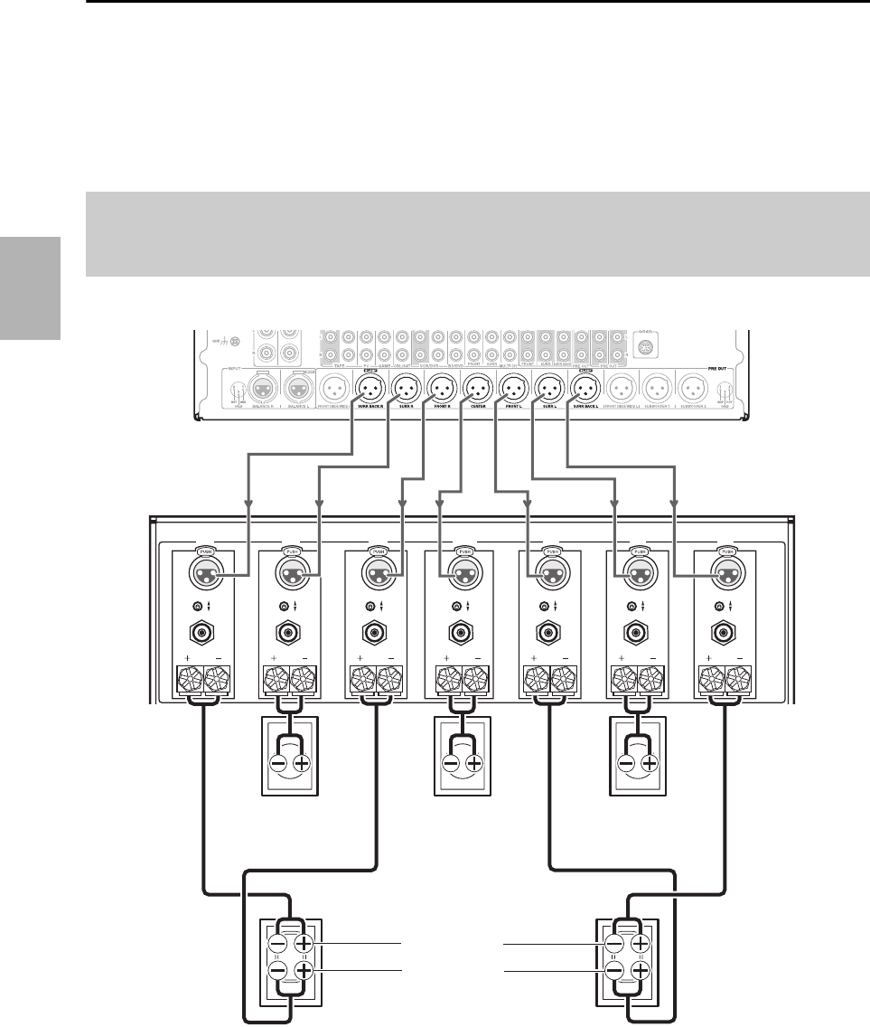
Connecting a Power Amplifier with XLR Inputs
You can connect the AV controller to a multichannel power amplifier with balanced XLR input jacks by using several
XLR audio cables.
The AV controller’s balanced PRE OUT jacks are wired as shown.
See your multichannel power amplifier’s instruction manual for more information on connecting speakers.
Note
*1 Specify crossover frequency for the channel that you want to output in “Speaker Configuration” (➔54).
*2 If you use the front high and wide speakers at the same time, you need to set the “Front High + Front Wide” setting to “Yes ”
(➔54).
SPEAKER IMPEDANCE
4 OHMS MIN. PER EACH
SPEAKER TERMINAL
AC INLET SEVEN CHANNEL AMPLIFIER
MODEL NO.
RDA-7.1
INPUT
SELECT
FUSE
SURROUND BACK
RIGHT
SURROUND
RIGHT
12V TRIGGER
IN OUT
SURROUND
LEFT
CENTER FRONT
LEFT
SURROUND BACK
LEFT
FRONT
RIGHT
INPUT
SELECT
INPUT
SELECT
INPUT
SELECT
INPUT
SELECT
INPUT
SELECT
INPUT
SELECT
OUTPUT OUTPUT OUTPUT OUTPUT OUTPUT OUTPUT OUTPUT
FRONT HIGH/
FRONTWIDE
LEFT
INPUT
SELECT
OUTPUT
FRONT HIGH/
FRONT WIDE
INPUT
SELECT
OUTPUT
RIGHT
AV controller
Multichannel
power amplifier
Surround
right
speaker
Front right
speaker
Center
speaker
Front left
speaker
Surround
left
speaker
Front high/
Front wide
right speaker*1
Surround
back/Front
wide right
speaker*2
Surround
back/Front
wide left
speaker*2
Front high/
Front wide
left speaker*1
15
En
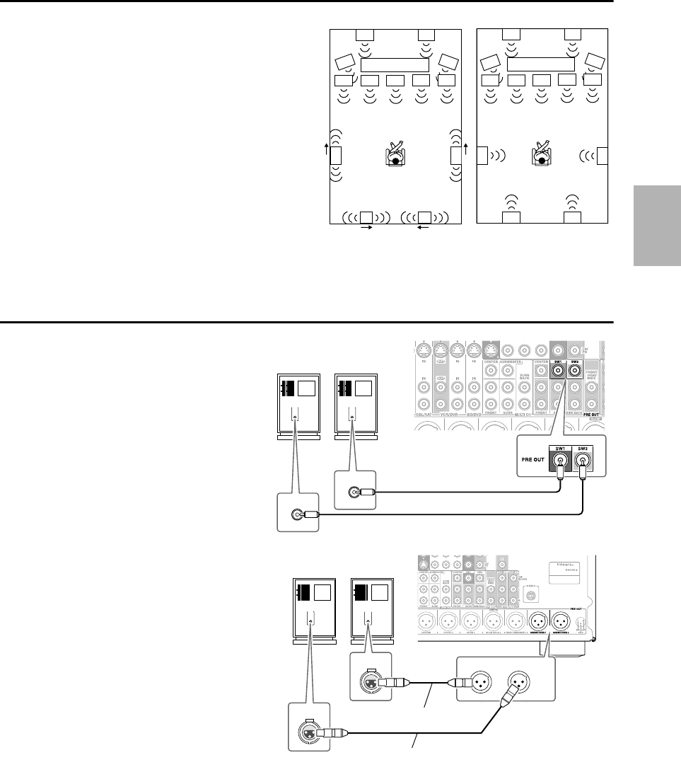
Using Dipole Speakers
You can use dipole speakers for the surround and surround
back speakers. Dipole speakers output the same sound in two
directions.
Dipole speakers typically have an arrow printed on them to
indicate how they should be positioned. The surround dipole
speakers should be positioned so that their arrows point
toward the TV/screen, while the surround back dipole speak-
ers should be positioned so that their arrows point toward
each other, as shown.
ab Front speakers
cCenter speaker
de Surround speakers
fSubwoofer(s)
gh Surround back speakers
ij Front high speakers
kl Front wide speakers
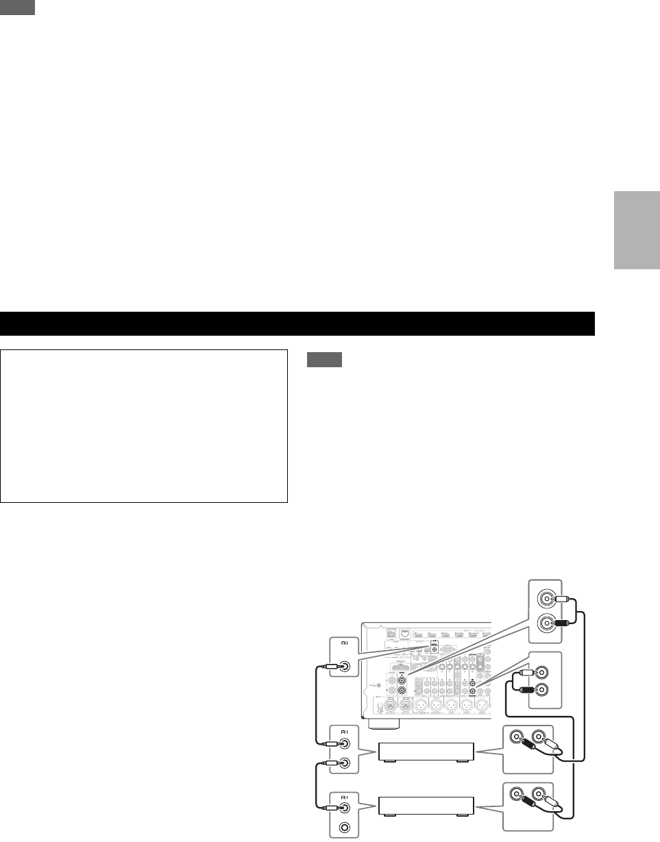
Connecting the Powered Subwoofers
Using a suitable cable, connect the AV controller’s
SW1 PRE OUT, SW2 PRE OUT to an input on
your powered subwoofer, as shown. If your sub-
woofer is unpowered and you’re using an external
amplifier, connect the SW1 PRE OUT, SW2
PRE OUT to an input on the amp.
You can connect the powered subwoofer with each
jacks respectively. Level and distance can be set
individually for each output. If you use one sub-
woofer, connect it to SW1 PRE OUT.
You can also connect a powered subwoofer to the AV
controller’s balanced SUBWOOFER 1 PRE OUT,
SUBWOOFER 2 PRE OUT jack by using a bal-
anced XLR cable.
You can connect the powered subwoofer with each
jacks respectively. Level and distance can be set indi-
vidually for each output. If you use one subwoofer,
connect it to SUBWOOFER 1 PRE OUT.
f
cb
a
gh
de
f
a
kk
b
lc
de
gh
ij
ij
l
ff
TV/screen TV/screen
Dipole speakers Normal speakers
LINE INPUT
LINE INPUT
LINE INPUT
LINE INPUT
Powered subwoofer
LINE INPUT LINE INPUT
PRE OUT
SUBWOOFER 1 SUBWOOFER 2
INPUT
INPUT
Powered subwoofer
Balanced XLR cable
Balanced XLR cable
16
En
Bi-amping the Front Speakers
The FRONT L/R and SURR BACK L/R outputs can be used with front speakers and surround back speakers, respec-
tively, or bi-amped to provide separate tweeter and woofer feeds for a pair of front speakers that support bi-amping, pro-
viding improved bass and treble performance.
• When bi-amping is used, the AV controller is able to feed up to 7.2 speakers in the main room.
• For bi-amping, the FRONT L/R outputs feed the front speakers’ woofer terminals. And the SURR BACK L/R
outputs feed the front speakers’ tweeter terminals.
• Once you’ve completed the bi-amping connections shown below and turned on the AV controller, you must set the
“Speakers Type(Front)” setting to “Bi-Amp” to enable bi-amping (➔54).
See your multichannel power amplifier’s instruction manual for more information on connecting speakers.
Important:
• When making the bi-amping connections, be sure to remove the jumper bars that link the speakers’ tweeter (high) and woofer (low)
terminals.
• Bi-amping can only be used with speakers that support bi-amping. Refer to your speaker manual.
SPEAKER IMPEDANCE
4 OHMS MIN. PER EACH
SPEAKER TERMINAL
AC INLET SEVEN CHANNEL AMPLIFIER
MODEL NO. RDA-7.1
INPUT
SELECT
FUSE
SURROUND BACK
RIGHT
SURROUND
12V TRIGGER
IN OUT
SURROUND
LEFT
CENTER FRONT
LEFT
SURROUND BACK
LEFT
FRONT
RIGHT
INPUT
SELECT
INPUT
SELECT
INPUT
SELECT
INPUT
SELECT
INPUT
SELECT
INPUT
SELECT
OUTPUT OUTPUT OUTPUT OUTPUT OUTPUT OUTPUT OUTPUT
RIGHT
AV controller
Multichannel
power amplifier
Surround right
speaker
Front right speaker
Center speaker
Front left speaker
Surround left
speaker
Tweeter (high)
Woofer (low)
17
En
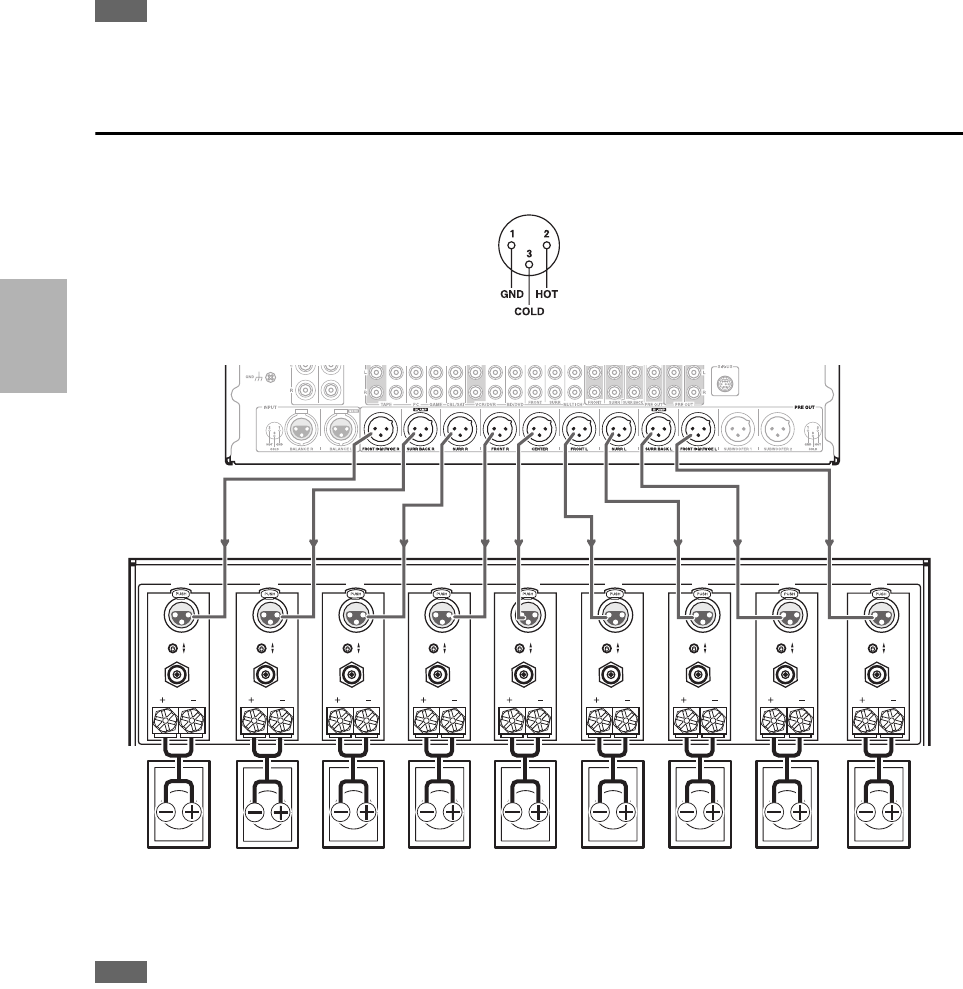
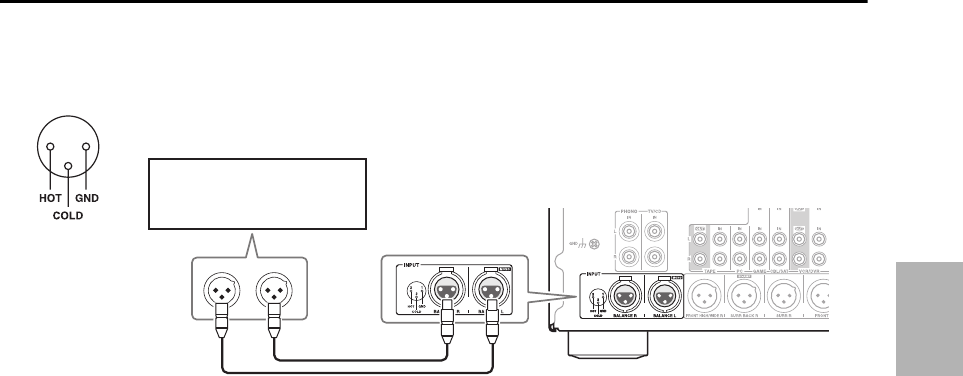
Connecting a Balanced Audio Source
You can connect a balanced audio source to the AV controller’s BALANCE L/R INPUT jacks by using two XLR audio
cables. To use the balanced input, you must assign it to an input selector (➔53). If you connect a mono source, use the
BALANCE L INPUT jack and set the “Input Channel” setting to “Mono(L)” (➔57). The AV controller’s balanced
INPUT jacks are wired as shown.
12
3
Stereo audio source with
balanced XLR output
18
En
Connected image with AV components
• Before making any AV connections, read the manuals supplied with your AV components.
• Don’t connect the power cord until you’ve completed and double-checked all AV connections.
• Push plugs in all the way to make good connections (loose connections can cause noise or malfunc-
tions).
• To prevent interference, keep audio and video cables away from power cords and speaker cables.
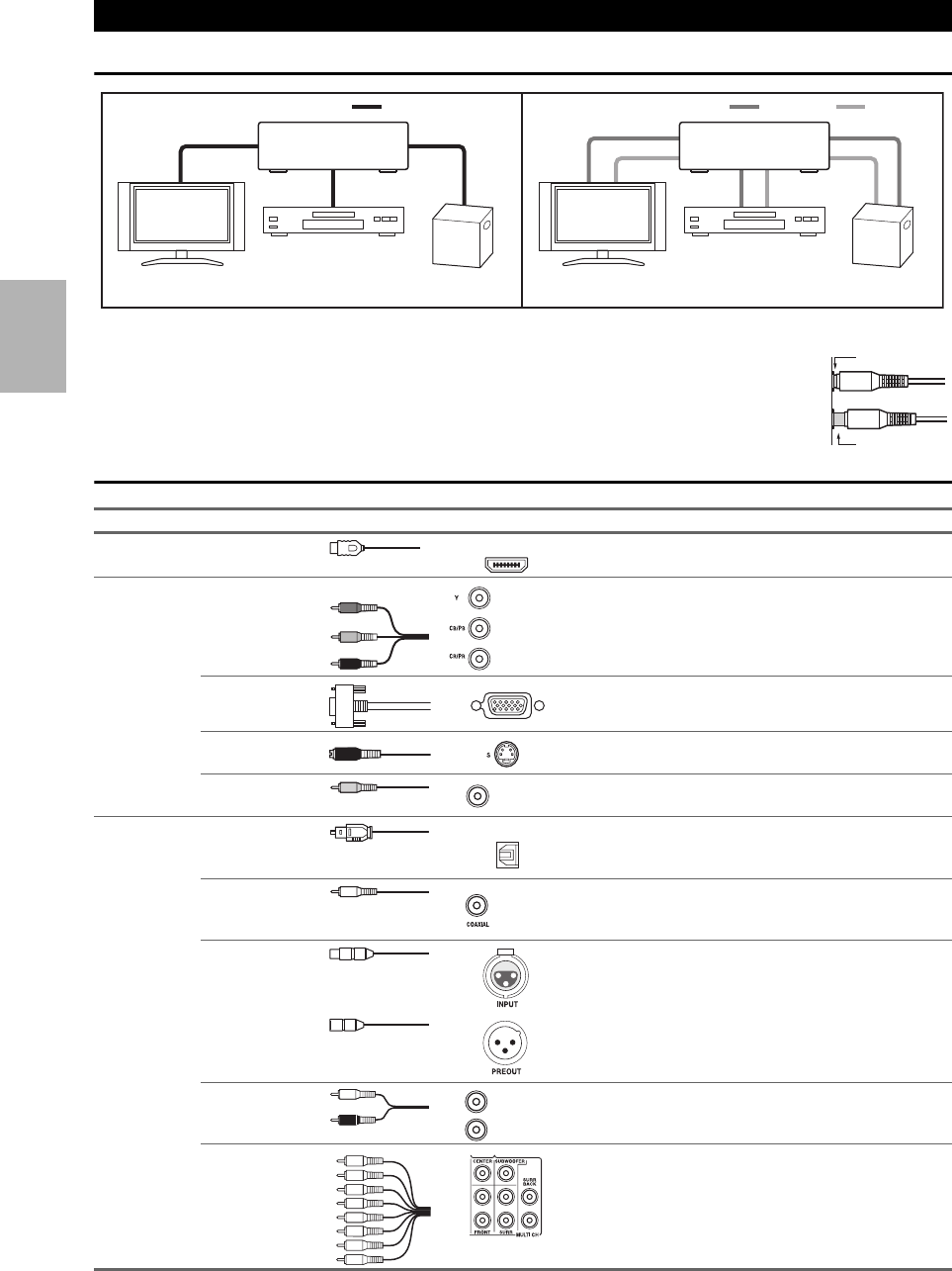
AV Cables and Jacks
*Available sampling rate for PCM input signal is 32/44.1/48/88.2/96 kHz. Even 176.4/192 kHz is effective in case of the HDMI con-
nection.
About AV Connections
Signal Cable Jack Description
Video and
Audio
HDMI HDMI connections can carry digital video and audio.
Video Component video Component video separates the luminance (Y) and color
difference signals (PB/CB, PR/CR), providing the best pic-
ture quality (some TV manufacturers label their compo-
nent video sockets slightly differently).
Analog RGB This is a conventional analog interface to connect a PC and
a display device (also called D-Sub or D-subminiature).
S-Video S-Video separates the luminance and color signals and pro-
vides better picture quality than composite video.
Composite video Composite video is commonly used on TVs, VCRs, and
other video equipment.
Audio Optical digital
audio
Optical digital connections allow you to enjoy digital
sound such as PCM*, Dolby Digital or DTS. The audio
quality is the same as coaxial.
Coaxial digital
audio
Coaxial digital connections allow you to enjoy digital
sound such as PCM*, Dolby Digital or DTS. The audio
quality is the same as optical.
Balanced XLR This cable carries analog audio. Balanced XLR cables are
used for better noise immunity and longer cable runs.
Analog audio
(RCA)
Analog audio connections (RCA) carry analog audio.
Multichannel ana-
log audio (RCA)
This cable carries multichannel analog audio and is typi-
cally used to connect DVD players with a 7.1-channel ana-
log audio output. Several standard analog audio cables can
be used instead of a multichannel cable.
HDMI cable Other cables
: Video & Audio : Video : Audio
Game console
Blu-ray
Disc/DVD player
TV, projector, etc. Game console
Blu-ray
Disc/DVD player
TV, projector, etc.
AV controller
AV controller
Right!
Wrong!
HDMI
Y
PB/CB
PR/CR
Green
Blue
Red
V
Yellow
OPTICAL
Orange
L
R
White
Red
19
En
Note
• The AV controller does not support SCART plugs.
• The AV controller’s optical digital jacks have shutter-type covers that open when an optical plug is inserted and close when it’s removed.
Push plugs in all the way.
Caution
• To prevent shutter damage, hold the optical plug straight when inserting and removing.
Connect your components to the appropriate jacks. The default input assignments are shown below.
✔: Assignment can be changed (➔51 to 52).
Refer to “About HDMI” (➔106) and “Using an RIHD-compatible TV, Player, or Recorder” (➔107).
■Audio return channel (ARC) function
Audio return channel (ARC) function enables an HDMI capable TV to send the audio stream to the HDMI OUT MAIN
of the AV controller. To use this function, you must select the TV/CD input selector.
• To use ARC function, you must select the TV/CD input selector, your TV must support ARC function and “HDMI
Control(RIHD)” is set to “On” (➔66).
Tip
• To listen to audio received by the HDMI IN jacks through your TV’s speakers:
– Set the “TV Control” setting to “On” (➔67) for an p-compatible TV.
– Set the “Audio TV Out” setting to “On” (➔66) when the TV is not compatible with p or the “TV Control” setting to “Off”.
– Set your Blu-ray Disc/DVD player’s HDMI audio output setting to PCM.
– To listen to TV audio through the AV controller, see “Connecting Your Components” (➔20).
Note
• When listening to an HDMI component through the AV controller, set the HDMI component so that its video can be seen on the TV
screen (on the TV, select the input of the HDMI component connected to the AV controller). If the TV power is off or the TV is set to
another input source, this may result in no sound from the AV controller or the sound may be cut off.
•When the “Audio TV Out” setting is set to “On” (➔66) to hear from your TV’s speakers, by controlling the AV controller’s volume,
the sound will be output from the AV controller’s speakers, too. When the “TV Control” setting is set to “On” (➔67) to hear from
speakers of p-compatible TV, by controlling the AV controller’s volume, the AV controller’s speakers will produce sound while
the TV’s speakers are muted. To stop the AV controller’s speakers producing sound, change the settings, change your TV’s settings, or
turn down the AV controller’s volume.
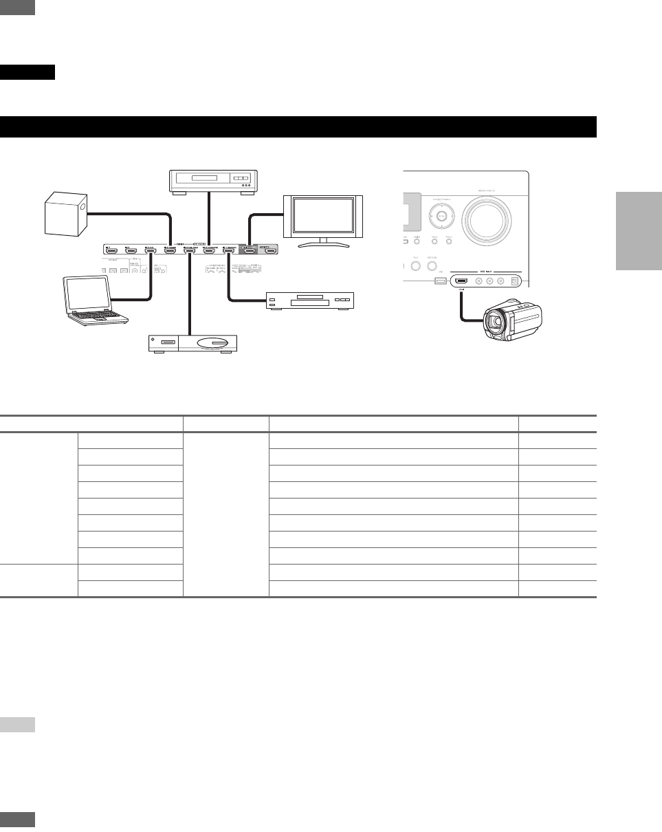
Connecting Your Components with HDMI
Jack Signal Components Assignable
Input HDMI IN 1 Audio/Video Blu-ray Disc/DVD player ✔
HDMI IN 2 VCR or DVD recorder/Digital Video Recorder ✔
HDMI IN 3 Satellite, cable, set-top box, etc. ✔
HDMI IN 4 Game console ✔
HDMI IN 5 Personal computer ✔
HDMI IN 6 Other components ✔
HDMI IN 7 Other components ✔
AUX Input HDMI Camcorder
Output HDMI OUT MAIN TV
HDMI OUT SUB Projector, etc.
Game console
VCR or DVD recorder/Digital Video Recorder
TV, projector, etc.
Satellite, cable, set-top box, etc.
Blu-ray Disc/DVD player
Camcorder
Personal
computer
20
En
Connect your components to the appropriate jacks. The default input assignments are shown below.
✔: Assignment can be changed (➔52, 53).
Connecting Your Components
No. Jack Signal Components Assignable
AAUX Input Video Composite video Camcorder, etc
Audio L/R Analog audio
Digital Digital audio
BCOMPONENT
VIDEO
IN 1 (BD/DVD) Component video Blu-ray Disc/DVD player ✔
IN 2 (CBL/SAT) Satellite, cable, set-top box, etc. ✔
IN 3 (GAME) Game console ✔
MONITOR OUT TV, projector, etc.
CDIGITAL COAXIAL IN 1 (BD/DVD) Digital audio Blu-ray Disc/DVD player ✔
IN 2 (VCR/DVR) VCR or DVD recorder/digital
video recorder
✔
IN 3 (CBL/SAT) Satellite, cable, set-top box, etc. ✔
OPTICAL IN 1 (GAME) Game console ✔
IN 2 (TV/CD) TV, CD player ✔
IN 3 Other components ✔
DMONITOR OUT Composite video
and S-Video
TV, projector, etc.
BD/DVD IN Analog audio,
composite video
and S-Video
Blu-ray Disc/DVD player
VCR/DVR IN VCR or DVD recorder/digital
video recorder
CBL/SAT IN Satellite, cable, set-top box, etc.
GAME IN Game console
PC IN Analog audio Personal computer
TAPE IN Cassette tape deck, MD, CD-R
TV/CD IN TV, CD player, Turntable*1
PHONO IN Turntable*1
EUNIVERSAL PORT Analog
audio/video
Universal port optional dock
(UP-A1 etc.)
FPC IN*2 Analog RGB Personal computer
GMultichannel input*3 Analog audio DVD player, DVD-Audio or
Super Audio CD-capable player,
or an MPEG decorder
✔
A
CB
F
G
D
E
Front
Rear
21
En
Note
*1 Connect a turntable (MM) that has built-in a phono preamp to TV/CD IN or connect it to PHONO IN with the phono preamp turned
off. If your turntable (MM) doesn’t have a phono preamp, connect to PHONO IN. If your turntable has a moving coil (MC) type car-
tridge, you’ll need a commercially available MC head amp or MC transformer to connect to PHONO IN. See your turntable’s man-
ual for details.
If your turntable has a ground wire, connect it to the AV controller’s GND screw. With some turntables, connecting the ground wire
may produce an audible hum. If this happens, disconnect it.
*2 When you connect your personal computer to PC IN and select PC input selector, video of the personal computer is output from
HDMI output. However, because the AV controller selects the video input in the order of HDMI > component > analog RGB, if you
have assigned HDMI IN to the PC input selector, the AV controller will output signals from HDMI IN in priority to PC IN.
*3 Before using the multichannel input, you must assign it to an input selector. See “Analog Audio Input” (➔53). To select the multi-
channel input, see “Audio Selector” (➔70). To adjust the subwoofer sensitivity for the multichannel input, see “Subwoofer Input
Sensitivity” (➔53).
• The AV controller can output audio and video signals from the AUX Input jacks to the VCR/DVR OUT jacks.
• With connection D, you can listen and record audio from the external components while you are in Zone 2 or 3. You can listen and
record audio from the external components in the main room; you can listen to the audio in Zone 2 or 3 as well.
• With connection C, you can enjoy Dolby Digital and DTS. (To record or listen in Zone 2 or 3 as well, use C and D.)
■How to record the video
With the connections described above, you cannot record the video through the AV controller. To make a connection for
video recording (➔41).
With u (Remote Interactive), you can use the following
special functions:
■Auto Power On
When you start playback on a component connected via
u while the AV controller is on Standby, the AV con-
troller will automatically turn on and select that compo-
nent as the input source.
■Direct Change
When playback is started on a component connected via
u, the AV controller automatically selects that compo-
nent as the input source.
■Remote Control
You can use the AV controller’s remote controller to
control your other u-capable Integra/Onkyo compo-
nents, pointing the remote controller at the AV control-
ler’s remote control sensor instead of the component.
You must enter the appropriate remote control code first
(➔94).
Note
•Use only u cables for u connections. u cables are supplied
with Integra/Onkyo players (DVD, CD, etc.).
• Some components have two u jacks. You can connect either
one to the AV controller. The other jack is for connecting addi-
tional u-capable components.
• Connect only Integra/Onkyo components to u jacks. Connect-
ing other manufacturer’s components may cause a malfunction.
• Some components may not support all u functions. Refer to
the manuals supplied with your other Integra/Onkyo compo-
nents.
• While Zone 2 and Zone 3 is on, the Auto Power On and Direct
Change u functions do not work.
• Do not use u connections if you use HDMI Control(RIHD)
(➔66).
Connecting Integra/Onkyo u Components
Step 1:
Make sure that each Integra/Onkyo component is con-
nected with an analog audio cable (connection D in the
hookup examples) (➔20).
Step 2:
Make the u connection (see illustration below).
Step 3:
If you’re using an RI Dock, or cassette tape deck,
change the Input Display (➔28).
IN
TV/CD
L
R
LR
IN
BD/DVD
L
R
REMOTE
CONTROL
ANALOG
AUDIO OUT
LR
ANALOG
AUDIO OUT
e.g., CD player
e.g., DVD player
22
En
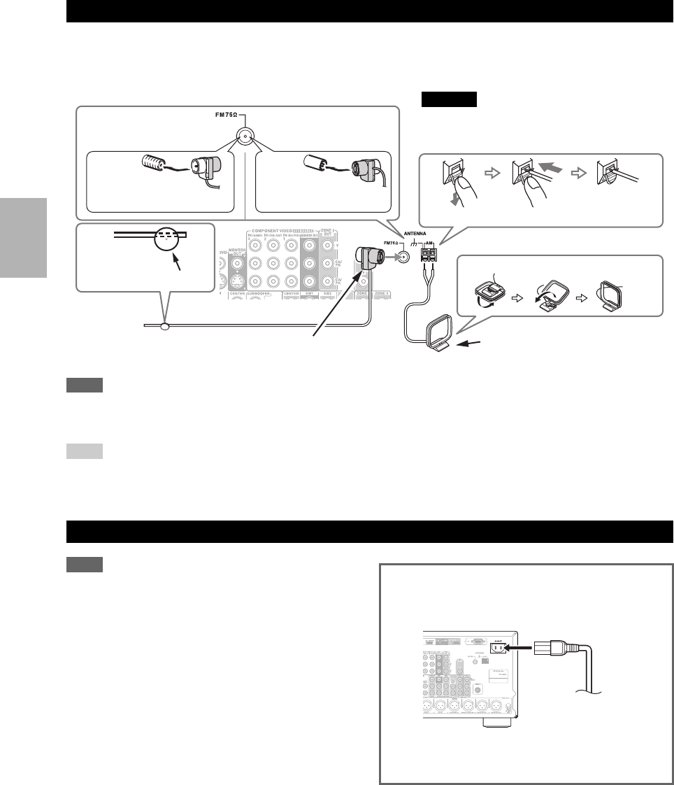
This section explains how to connect the supplied indoor FM antenna and AM loop antenna.
The AV controller won’t pick up any radio signals without any antenna connected, so you must connect the antenna to
use the tuner.
Note
• Once your AV controller is ready for use, you’ll need to tune into a radio station and position the antenna to achieve the best possible
reception.
• Keep the AM loop antenna as far away as possible from your AV controller, TV, speaker cables, and power cords.
Tip
• If you cannot achieve good reception with the supplied indoor FM antenna, try a commercially available outdoor FM antenna instead.
• If you cannot achieve good reception with the supplied indoor AM loop antenna, try using it with a commercially available outdoor AM
antenna.
Note
• Before connecting the power cord, connect all of your speak-
ers and AV components.
• Turning on the AV controller may cause a momentary power
surge that might interfere with other electrical equipment on the
same circuit. If this is a problem, plug the AV controller into a
different branch circuit.
• Do not use a power cord other than the one supplied with the AV
controller. The supplied power cord is designed exclusively for
use with the AV controller and should not be used with any other
equipment.
• Never disconnect the power cord from the AV controller while
the other end is still plugged into a wall outlet. Doing so may
cause an electric shock. Always disconnect the power cord from
the wall outlet first, and then the AV controller.
Connecting Antenna
Connecting the Power Cord
Thumbtacks, etc.
Insert the plug fully
into the jack.
Insert the plug fully
into the jack.
(North American
models)
(Australian models)
Push.
Assembling the AM loop antenna.
Indoor FM antenna (supplied) AM loop antenna (supplied)
Caution
• Be careful that you don’t injure yourself when
using thumbtacks.
Insert wire. Release.
Step 1:
Connect the supplied power cord to the AV controller’s
AC INLET.
Step 2:
Plug the power cord into an AC wall outlet.
To AC wall outlet
23
En
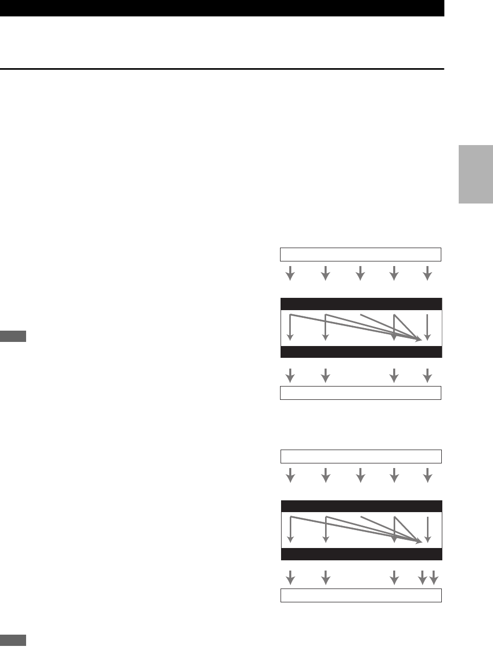
The AV controller supports several connection formats for compatibility with a wide range of AV equipment. The format
you choose will depend on the formats supported by your components. Use the following sections as a guide.
Video Connection Formats
Video component can be connected by using any one of the following video connection formats: composite video,
S-Video, PC IN (Analog RGB), component video or HDMI, the latter offering the best picture quality.
The AV controller can upconvert and downconvert between video formats, depending on the “Monitor Out” setting
(➔50), which generally determines whether video signals are upconverted for the component video output or the HDMI
output.
For optimal video performance, THX recommends that video signals pass through the system without upconver-
sion (e.g., component video input through to component video output).
To by-pass video upconversion in the AV controller, simultaneously press the VCR/DVR and Return on the AV
controller. While continuing to hold down the VCR/DVR, press Return to toggle until “Skip” appears on the dis-
play. Release both buttons.
To use the video upconversion in the AV controller, repeat the above process until “Use” appears on the display and
release the buttons.
■“Monitor Out” setting set to “HDMI Main” or “HDMI Sub”
Video input signals flow through the AV controller as
shown, with composite video, S-Video, PC IN (Analog
RGB) and component video sources all being upconverted
for the HDMI output. Use these settings if you connect the
AV c o n t r o l l e r ’ s HDMI OUT MAIN or HDMI OUT SUB,
respectively, to your TV.
The composite video, S-Video and component video outputs
pass through their respective input signals as they are.
Note
• If not connected to the same output you have selected in the “Mon-
itor Out” setting, the “Monitor Out” setting will be automatically
switched to “Analog” (➔24).
In this case, the setting of the output resolution will be that for
HDMI output (➔50). Moreover, it will be switched to “1080i”
when “1080p” or “1080p/24” is selected, and to “Through” when
“Auto” is selected.
■“Monitor Out” setting set to “Both”, “Both(Main)” or “Both(Sub)”
Video input signals flow through the AV controller as
shown, with composite video, S-Video, PC IN (Analog
RGB) and component video sources all being upconverted
for both HDMI outputs. Use these settings if you connect
the AV controller’s HDMI OUT MAIN and HDMI OUT
SUB to your TVs.
The composite video, S-Video and component video outputs
pass through their respective input signals as they are.
`Both: Video signals are output from both HDMI outputs
at the resolution supported by both TVs. You cannot
select “Resolution” setting.
`Both(Main): Video signals are output from both HDMI
outputs but HDMI OUT MAIN will become a priority;
depending on the resolution, video signals may not be
output from HDMI OUT SUB.
`Both(Sub): Video signals are output from both HDMI outputs but HDMI OUT SUB will become a priority; depend-
ing on the resolution, video signals may not be output from HDMI OUT MAIN.
Note
•The “Monitor Out” setting will be automatically switched to “Analog” (➔50) if not connected to both outputs when “Both” is
selected or if not connected to a priority output when “Both(Main)” or “Both(Sub)” is selected.
Which Connections Should I Use?
IN
MONITOR OUT
Blu-ray Disc/DVD player, etc.
AV controller
TV, projector, etc.
Video Signal Flow Chart
Composite S-Video Component HDMI
Composite S-Video Component HDMI
PC IN
(Analog RGB)
IN
MONITOR OUT
AV controller
Composite
Composite S-Video Component
Video Signal Flow Chart
HDMI
HDMI
TV, projector, etc
Blu-ray Disc/DVD player, etc.
S-Video Component
PC IN
(Analog RGB)
24
En
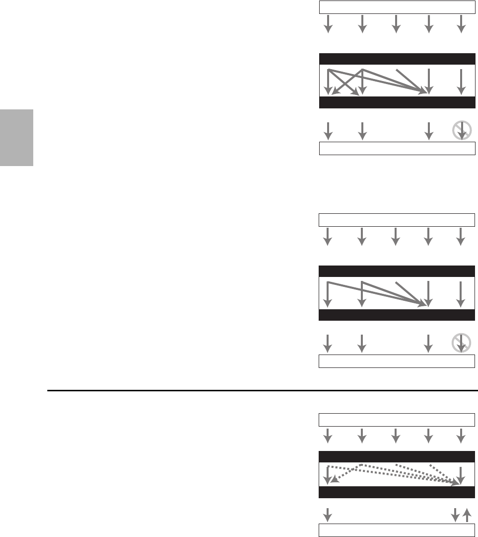
■“Monitor Out” setting set to “Analog”
Video input signals flow through the AV controller as
shown, with composite video, S-Video and PC IN (Analog
RGB) sources being upconverted for the component video
output. Use this setting if you connect the AV control-
ler’s COMPONENT VIDEO MONITOR OUT to your
TV.
Composite video is upconverted to S-Video and S-Video is
downconverted to composite video. Note that these conver-
sions only apply to the MONITOR OUT V and S outputs,
not the VCR/DVR OUT V and S outputs.
The composite video, S-Video and component video out-
puts pass through their respective input signals as they are.
This signal flow also applies when the “Resolution” set-
ting is set to “Through” (➔51).
Video Signal Flow and the Resolution Setting
When the “Monitor Out” setting is set to “Analog”
(➔50), if the “Resolution” setting is set to anything other
than “Through” (➔51), the video signal flow will be as
shown here, with composite video, PC IN (Analog RGB)
and S-Video sources being upconverted for the component
video output.
The composite video, S-Video and component video out-
puts pass through their respective analog input signals as
they are. HDMI input signals are not output.
Audio Connection Formats
Audio component can be connected by using any of the
following audio connection formats: analog, analog multi-
channel, optical, coaxial, or HDMI.
When choosing a connection format, bear in mind that the
AV controller does not convert digital input signals for
analog line outputs and vice versa. For example, audio sig-
nals connected to an optical or coaxial digital input are not
output by the analog VCR/DVR OUT.
If signals are present at more than one input, the inputs
will be selected automatically in the following order of pri-
ority: HDMI, digital, analog.
IN
MONITOR OUT
*
1
Blu-ray Disc/DVD player, etc.
AV controller
TV, projector, etc.
Composite
Composite S-Video Component
Video Signal Flow Chart
HDMI
HDMI
*1 For details, refer to “Video Resolution
Chart” (➔113).
S-Video Component
PC IN
(Analog RGB)
IN
MONITOR OUT
AV controller
TV, projector, etc.
Blu-ray Disc/DVD player, etc.
Composite
Composite S-Video Component
Video Signal Flow Chart
HDMI
HDMI
S-Video Component
PC IN
(Analog RGB)
IN
OUT
*1*2
*1
*1
*1
*3
*1*3
Blu-ray Disc/DVD player, etc.
AV controller
TV, projector, etc.
HDMICoaxial Analog
Audio Signal Flow Chart
HDMI Analog
Multichannel
*1 Depends on the “Audio TV Out” setting (➔66).
*2 This setting is available when “Audio Return Channel”
setting is set to “Auto” (➔66). You must select the TV/CD
input selector and your TV must support ARC function.
*3 Only the front L/R channels are output.
Optical
25
En
Turning On & Basic Operations
Turning On/Off the AV Controller
Turning On
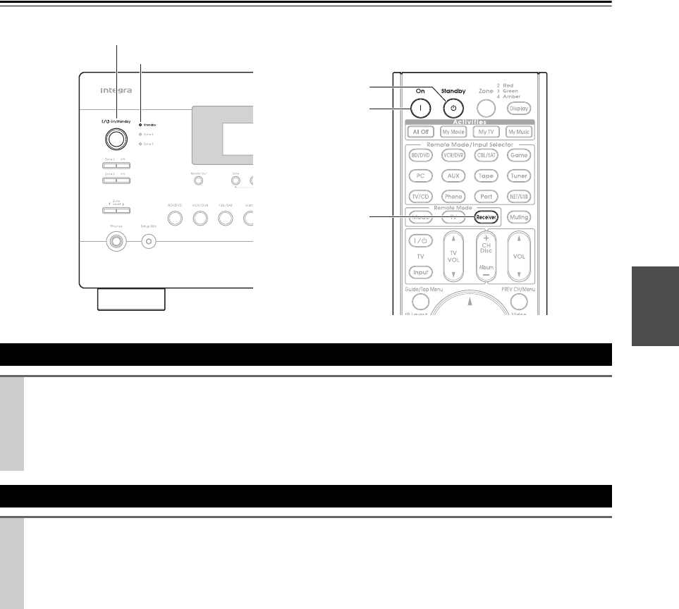
Press On/Standby on the front panel.
or
Press Receiver followed by On on the remote controller.
The AV controller comes on, the display lights, and the Standby indicator goes off.
Pressing the remote controller’s On again will turn on any components connected via u.
Turning Off
Press On/Standby on the front panel.
or
Press Receiver followed by Standby on the remote controller.
The AV controller will enter Standby mode. To prevent any loud surprises when you turn on the AV controller,
always turn down the volume before you turn it off.
On
Receiver
Standby
On/Standby
Standby indicator
26
En
Basic Operations
You can determine the language used for the onscreen
setup menus. See “Language” in the “OSD Setup”
(➔65).
■Operating on the AV controller
■Operating with the remote controller
You can display various information about the current
input source as follows. (Components connected to the
UNIVERSAL PORT jack are excluded.)
Tip
• Alternatively, you can use the AV controller’s Display.
The following information can typically be displayed.
*1 The input source is displayed with the default name even
when you have entered a custom name in “Name Edit”
(➔61).
*2 If the input signal is analog, no format information is dis-
played. If the input signal is PCM, the sampling frequency is
displayed. If the input signal is digital but not PCM, the signal
format and the number of channels is displayed. For some dig-
ital input signals, including multichannel PCM, the signal for-
mat, number of channels, and sampling frequency is
displayed.
Information is displayed for about three seconds, then the pre-
viously displayed information reappears.
You can adjust the brightness of the AV controller’s dis-
play.
Tip
•(North American models) Alternatively, you can use the AV
controller’s Dimmer.
This manual describes the procedure using the
remote controller unless otherwise specified.
Selecting the Language Used for the
Onscreen Setup Menus
Playing the Connected Component
1Use the input selector buttons to select the input
source.
2Start playback on the source component.
See also:
• “Controlling Other Components” (➔92)
• “Controlling iPod” (➔87)
• “Listening to the Radio” (➔32)
3To adjust the volume, use the Master Volume
control.
4Select a listening mode and enjoy!
See also:
• “Using the Listening Modes” (➔42)
• “Audyssey” (➔59)
1Press Receiver followed by Input Selector.
2Start playback on the source component.
See also:
• “Controlling Other Components” (➔92)
• “Controlling iPod” (➔87)
• “Listening to the Radio” (➔32)
3To adjust the volume, use VOL q/w.
4Select a listening mode and enjoy!
See also:
• “Using the Listening Modes” (➔42)
• “Audyssey” (➔59)
Displaying Source Information
Press Receiver followed by Display repeatedly to
cycle through the available information.
Setting the Display Brightness
Press Receiver followed by Dimmer repeatedly
to select: dim, dimmer, or normal brightness.
Sampling
frequency
Input source
Signal format*2
Input signal
resolution
Output
resolution
Listening
mode*1

27
En
You can temporarily mute the output of the AV controller.
Tip
• To unmute, press Muting again or adjust the volume.
• The Mute function is cancelled when the AV controller is set to
Standby.
With the sleep timer, you can set the AV controller to turn
off automatically after a specified period.
Tip
• If you need to cancel the sleep timer, press Sleep repeatedly
until the SLEEP indicator goes off.
• To check the time remaining until the AV controller sleeps, press
Sleep. Note that if you press Sleep while the sleep time is
being displayed, you’ll shorten the sleep time by 10 minutes.
The Home menu provides you quick access to frequently
used menus without having to go through the long stan-
dard menu. This menu enables you to change settings and
view the current information.
Note
*1 Only when you have selected “Custom” in the “Picture
Mode” (➔62), pressing Enter allows you to adjust the fol-
lowing items via the Home menu; “Brightness”, “Contrast”,
“Hue” and “Saturation”. Press Return to return to the pic-
ture mode setting.
*2 Depending on the input source and listening mode, not all
channels shown here output the sound.
*3 When you have entered a custom name in “Name Edit”
(➔61), the input source is displayed with that name. But
even if not, the component name may be displayed if the AV
controller receives it via HDMI connection (➔19).
*4 For the Port input selector, the name of Universal Port Option
Dock will be displayed.
Muting the AV Controller
Press Receiver followed by Muting.
The output is muted and the MUTING indicator
flashes on the display.
Using the Sleep Timer
Press Receiver followed by Sleep repeatedly to
select the required sleep time.
The sleep time can be set from 90 to 10 minutes in
10 minute steps.
The SLEEP indicator lights on the display when the
sleep timer has been set. The specified sleep time
appears on the display for about 5 seconds, then the
previous display reappears.
Using the Home Menu
1Press Receiver followed by Home.
The following information will be superimposed on
the TV screen.
(The language is English only.)
BD/DVD
Audio
Video
Info
Input
Listening Mode
2Use q/w/e/r to make the desired selection.
■Audio
`Performs audio settings. For details, refer to
“Using the Audio Settings” (➔68).
■Video*1
`You can change the following settings: “Wide
Mode”, “Picture Mode”, “Brightness”, “Con-
trast”, “Hue” and “Saturation”.
The remote controller’s Video acts as a shortcut
for this menu.
See also:
• “Picture Adjust” (➔62)
■Info*2*3
`You can view the information of the following
items: “Audio”, “Video” and “Tuner”.
■Input*3*4
`You can select the input source while viewing
the information as follows: the name of input
selectors, input assignments, and radio informa-
tion, and ARC function setting.
Press Enter to display the current input source,
followed by q/w to select the desired input
source. Pressing Enter again switches to the
selected input source.
■Listening Mode
`You can select the listening modes that are
grouped in the following categories:
“Movie/TV”, “Music”, “Game” and “THX”.
Use q/w to select the category and e/r to
select the listening mode. Press Enter to
switch to the selected listening mode.
28
En
When you connect an u-capable Onkyo component, you
must configure the input display so that u can work
properly.
This setting can be done only from the front panel.
Note
•DOCK can be selected for the Tape, Game or VCR/DVR input
selector, but not at the same time.
• Enter the appropriate remote control code before using the
remote controller for the first time (➔92).
Note
• Always turn down the volume before connecting your head-
phones.
• While the headphones plug is inserted in the Phones jack, the
Headphone indicator, speaker/channel indicator FL and FR
lights.
• When you connect a pair of headphones, the listening mode is
set to Stereo, unless it’s already set to Stereo, Mono or Direct.
• Only the Stereo, Direct and Mono listening modes can be used
with headphones.
You can use Activities to execute a number of remote
control operations with a single button.
This button has the following two modes.
`Easy Macro mode:
You can turn on and off the AV controller, playback
components and TV.
`Normal Macro mode:
You can assign desired operations (➔97, 99).
Note
• If you set any one of the Activities to Normal Macro mode, all
the Activities will be set to Normal Macro mode.
• To use Activities, first assign the remote control codes of the
AV components you are using (➔94).
Starting Components Using Activities
*1 Depending on the start-up time of the playback component,
the AV controller may not be able to activate the playback
command. In this case, press 1 on the remote controller.
Changing the Input Display
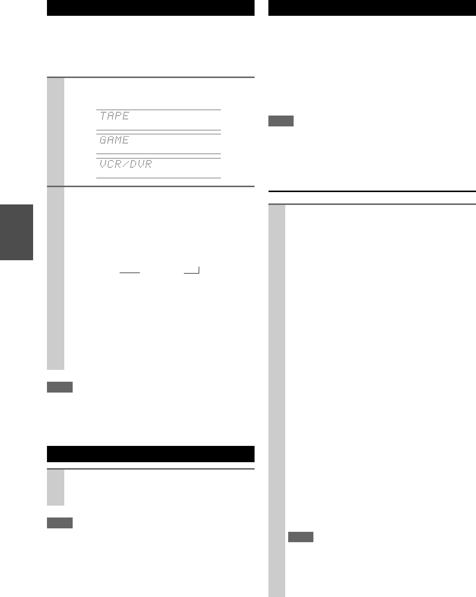
1Press Tape, Game or VCR/DVR so that “TAPE”,
“GAME” or “VCR/DVR” appears on the display.
2Press and hold down Tape, Game or VCR/DVR
(about 3 seconds) to change the input display.
Repeat this step to select “MD”, “CDR” or
“DOCK”.
For the Tape input selector, the input display
changes in this order:
For the Game input selector, the setting changes in
this order:
For the VCR/DVR input selector, the setting
changes in this order:
Using Headphones
Connect a pair of stereo headphones with a stan-
dard plug (1/4 inch or 6.3 mm) to the Phones
jack.
TAPE → MD → CDR
DOCK
→
→
GAME ↔ DOCK
VCR/DVR ↔ DOCK
Using Activities to Start Easy Macros
Press My Movie, My TV, or My Music.
At purchase, Activities are set to Easy Macro mode
as the default setting.
The default actions are described below.
My Movie:
1. The TV turns on.
2. The playback component assigned to BD/DVD
of Remote Mode turns on.
3. The AV controller turns on.
4. The input selector of the AV controller is set to
BD/DVD.
5. Playback begins on the playback component
assigned to BD/DVD.*1
My TV:
1. The TV turns on.
2. The playback component assigned to CBL/SAT
of Remote Mode turns on.
3. The AV controller turns on.
4. The input selector of the AV controller is set to
CBL/SAT.
My Music:
1. The playback component assigned to TV/CD of
Remote Mode turns on.
2. The AV controller turns on.
3. The input selector of the AV controller is set to
TV/CD.
4. Playback begins on playback component
assigned to TV/CD.*1
Note
• After pressing one of the Activities, you cannot use other
Activities until the assigned actions have been com-
pleted.
• If you wish to use another of the Activities after starting,
press All Off and then press the desired Activities.

29
En
Turning Off the Components
*2 When the last-pressed Activities is My Music, the TV will
not turn off.
Changing the Playback Components
Assigned to Activities
You can change the playback components assigned to the
Activities of Easy Macro mode using the following pro-
cedure.
Restoring Default
With the supplied calibrated microphone,
Audyssey MultEQ XT32 automatically determines the
number of speakers connected, their size for purposes of
bass management, optimum crossover frequencies to the
subwoofer (if present), and distances from the primary lis-
tening position.
Audyssey MultEQ XT32 then removes the distortion
caused by room acoustics by capturing room acoustical
problems over the listening area in both the frequency and
time domain. The result is clear, well-balanced sound for
everyone. Enabling Audyssey MultEQ XT32 allows you
to also use Audyssey Dynamic EQ®, which maintains the
proper octave-to-octave balance at any volume level
(➔59).
Before using this function, connect and position all of
your speakers.
If “Dynamic EQ” is set to “On” (➔59), the “Equalizer”
setting will be set to “Audyssey” (➔56). On the other
hand, if it is set to “Off”, the “Dynamic Volume” setting
will be set to “Off” (➔60).
It takes about 30 minutes to complete
Audyssey MultEQ XT32 Room Correction and Speaker
Setup for 8 positions. Total measurement time varies
depending on the number of speakers.
Using Audyssey MultEQ XT32
Using Audyssey MultEQ XT32 to create a listening envi-
ronment in your home theater that all listeners will enjoy,
Audyssey MultEQ XT32 takes measurements at up to
8 positions within the listening area. Position the micro-
phone at ear height of a seated listener with the micro-
phone tip pointed directly at the ceiling using a tripod. Do
not hold the microphone in your hand during measure-
ments as this will produce inaccurate results.
■First measurement position
Also referred to as the Main Listening Position this
refers to the most central position where one would nor-
mally sit within the listening environment.
MultEQ XT32 uses the measurements from this posi-
tion to calculate speaker distance, level, polarity, and the
optimum crossover value for the subwoofer.
■Second−Eighth measurement positions
These are the other listening positions (i.e., the places
where the other listeners will sit). You can measure up
to 8 positions.
The following examples show some typical home theater
seating arrangements. Choose the one that best matches
yours, and position the microphone accordingly when
prompted.
Press All Off.
The playback component assigned to the
last-pressed Activities, the AV controller, and the
TV turn off.*2
While holding down Remote Mode for the rele-
vant playback component, press and hold down
Activities to which you wish to assign this compo-
nent for about 3 seconds.
Activities will flash twice, indicating that the
change is complete.
Examples:
If you wished to use My Movie to start the playback
component assigned to VCR/DVR of Remote
Mode, you would press and hold down My Movie
for about 3 seconds while pressing down VCR/DVR
of Remote Mode.
Tip
• This procedure can also be performed via onscreen menu
(➔97).
1While holding down Home, press and hold down
All Off until All Off lights (about 3 seconds).
2Release Home and All Off and press All Off
again.
All Off flashes twice.
Audyssey MultEQ®XT32 Room
Correction and Speaker Setup
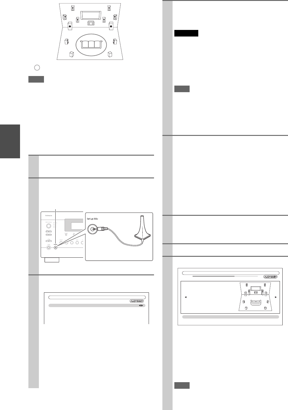
30
En
Note
• Make the room as quiet as possible. Background noise and Radio
Frequency Interference (RFI) can disrupt the room measure-
ments. Close windows, televisions, radios, air conditioners, flu-
orescent lights, home appliances, light dimmers, or other
devices. Turn off the cell phone (even if it is not in use) or place
it away from all audio electronics.
• The microphone picks up test tones which played through each
speaker as Audyssey MultEQ®XT32 Room Correction and
Speaker Setup run.
• Audyssey MultEQ XT32 Room Correction and Speaker Setup
cannot be performed while a pair of headphones is connected.
1Turn on the AV controller and the connected TV.
On the TV, select the input to which the AV control-
ler is connected.
2Set the speaker setup microphone at the Main Lis-
tening Position a, and connect it to the Setup
Mic jack.
The speaker setting menu appears.
3When you’ve finished making the settings, press
Enter.
• If you change “Speakers Type(Front)” or “Front
High + Front Wide” setting, refer to “Speaker Set-
tings” for more details (➔54).
• In accordance with the connected speakers, set the
“Front High / Front Wide Preout” setting to
“Front High” or “Front Wide”.
• If you are using a subwoofer(s), select “1ch” or
“2ch” in the “Subwoofer” (➔54). If not, select
“No” and skip step 4.
TV
de
gh
f
cab
: Listening area a to h: Listening position
Speaker setup microphone
Setup Mic jack
MultEQ XT32: Auto Setup
Speakers Type(Front)
Front High + Front Wide
Front High / Front Wide Preout
Subwoofer
Normal
No
Front High
1ch
4If you use a powered subwoofer(s), adjust the sub-
woofer volume level to 75dB.
Test tones are played through the subwoofer. Use the
volume control on the subwoofer.
Caution
• When the “Subwoofer” setting is set to “1ch”, the
left-hand subwoofer (SW1) alone will be measured.
When the “Subwoofer” setting is set to “1ch” with two
subwoofers connected, the right-hand subwoofer (SW2)
will not be measured and no sound will be output.
• An error will occur if you set “Subwoofer” to “2ch” with-
out connecting any subwoofers, or with only one sub-
woofer connected.
Note
• If your subwoofer does not have a volume control, disre-
gard the level displayed and press Enter to proceed to the
next step.
• If you set the subwoofer’s volume control to its maximum
and the displayed level is lower than 75 dB, leave the sub-
woofer’s volume control at its maximum and press Enter
to proceed to the next step.
5Press Enter.
Audyssey MultEQ XT32 Room Correction and
Speaker Setup starts.
Test tones are played through each speaker as
Audyssey MultEQ XT32 Room Correction and
Speaker Setup runs. This process takes a few min-
utes. Please refrain from talking during measure-
ments and do not stand between speakers and the
microphone.
Do not disconnect the speaker setup microphone dur-
ing Audyssey MultEQ XT32 Room Correction and
Speaker Setup, unless you want to cancel the setup.
6Place the setup microphone at the next position,
and then press Enter.
Audyssey MultEQ XT32 performs more measure-
ments. This takes a few minutes.
7When prompted, repeat step 6.
8Use q/w to select an option, and then press Enter.
The options are:
`Save:
Save the calculated settings and exit
Audyssey MultEQ XT32 Room Correction and
Speaker Setup.
`Cancel:
Cancel Audyssey MultEQ XT32 Room Correc-
tion and Speaker Setup.
Note
• You can view the calculated settings for the speaker con-
figuration, speaker distances, and speaker levels by using
e/r.
TV
MultEQ XT32: Auto Setup
Subwoofer 2ch
Front 40Hz
Center 40Hz
Surround 100Hz
Front Wide None
Front High 100Hz
Surround Back 120Hz
Surround Back Ch 2ch
Save
Cancel
- - Review Speaker Configuration - -
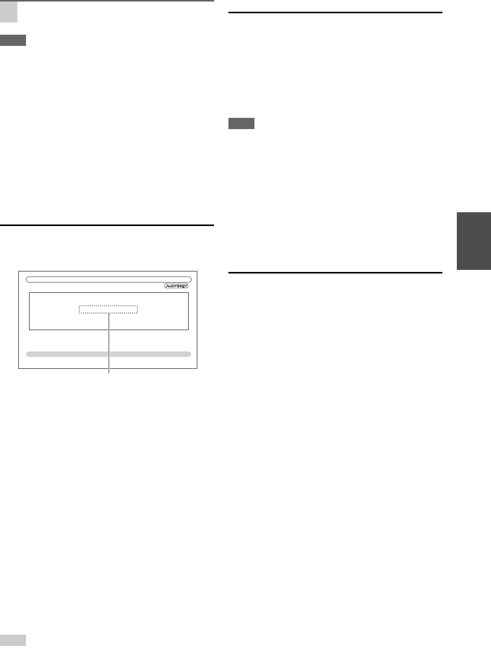
31
En
Note
• When Audyssey MultEQ®XT32 Room Correction and Speaker
Setup is complete, the “Equalizer” will be set to “Audyssey”
(➔56). The Audyssey indicator will light (➔9).
• You can cancel Audyssey MultEQ XT32 Room Correction and
Speaker Setup at any point in this procedure simply by discon-
necting the setup microphone.
• Do not connect or disconnect any speakers during
Audyssey MultEQ XT32 Room Correction and Speaker Setup.
• If the AV controller is muted, it will be unmuted automatically
when Audyssey MultEQ XT32 Room Correction and Speaker
Setup starts.
• Changes to the room after Audyssey MultEQ XT32 Room Cor-
rection and Speaker Setup requires you run
Audyssey MultEQ XT32 Room Correction and Speaker Setup
again, as room EQ characteristics may have changed.
Error Messages
While Audyssey MultEQ XT32 Room Correction and
Speaker Setup is in progress, one of the error messages
below may appear.
The options are:
`Retry:
Try again.
`Cancel:
Cancel Audyssey MultEQ XT32 Room Correction
and Speaker Setup.
• Ambient noise is too high.
The background noise is too loud. Remove the source of
the noise and try again.
• Speaker Matching Error!
The number of speakers detected was different from
that of the first measurement. Check the speaker con-
nection.
•Writing Error!
This message appears if saving fails. Try saving again.
If this message appears after 2 or 3 attempts, contact the
dealer from whom you purchased this unit.
• Speaker Detect Error
This message appears if a speaker is not detected. “No”
means that no speaker was detected.
Tip
• See “Speaker Configuration” for appropriate settings (➔54).
Changing the Speaker Settings Manually
You can manually make changes to the settings found dur-
ing Audyssey MultEQ XT32 Room Correction and
Speaker Setup.
See also:
• “Speaker Configuration” (➔54)
• “Speaker Distance” (➔55)
• “Level Calibration” (➔55)
• “Equalizer Settings” (➔56)
Note
• Please note that THX recommends any THX main speakers be
set to “80Hz(THX)”. If you set up your speakers using
Audyssey MultEQ XT32 Room Correction and Speaker
Setup, please make sure manually that any THX speakers are set
to 80 Hz (THX) crossover (➔54).
• Sometimes due to the electrical complexities of subwoofers and
the interaction with the room, THX recommends setting the level
and the distance of the subwoofer manually.
• Sometimes due to interaction with the room, you may notice
irregular results when setting the level and/or distance of the
main speakers. If this happens, THX recommends setting them
manually.
Using a Powered Subwoofer
If you’re using a powered subwoofer and it outputs very
low-frequency sound at a low volume level, it may not be
detected by Audyssey MultEQ XT32 Room Correction
and Speaker Setup.
If the “Subwoofer” appears on the “Review Speaker
Configuration” screen as “No”, increase the subwoofer’s
volume to the half-way point, set it to its highest crossover
frequency, and then try running Audyssey MultEQ XT32
Room Correction and Speaker Setup again. Note that if
the volume is set too high and the sound distorts, detection
issues may occur, so use an appropriate volume level. If
the subwoofer has a low-pass filter switch, set it to Off or
Direct. Refer to your subwoofer’s instruction manual for
details.
9Disconnect the speaker setup microphone.
Ambient noise is too high.
Retry
Cancel
MultEQ XT32: Auto Setup
Error message
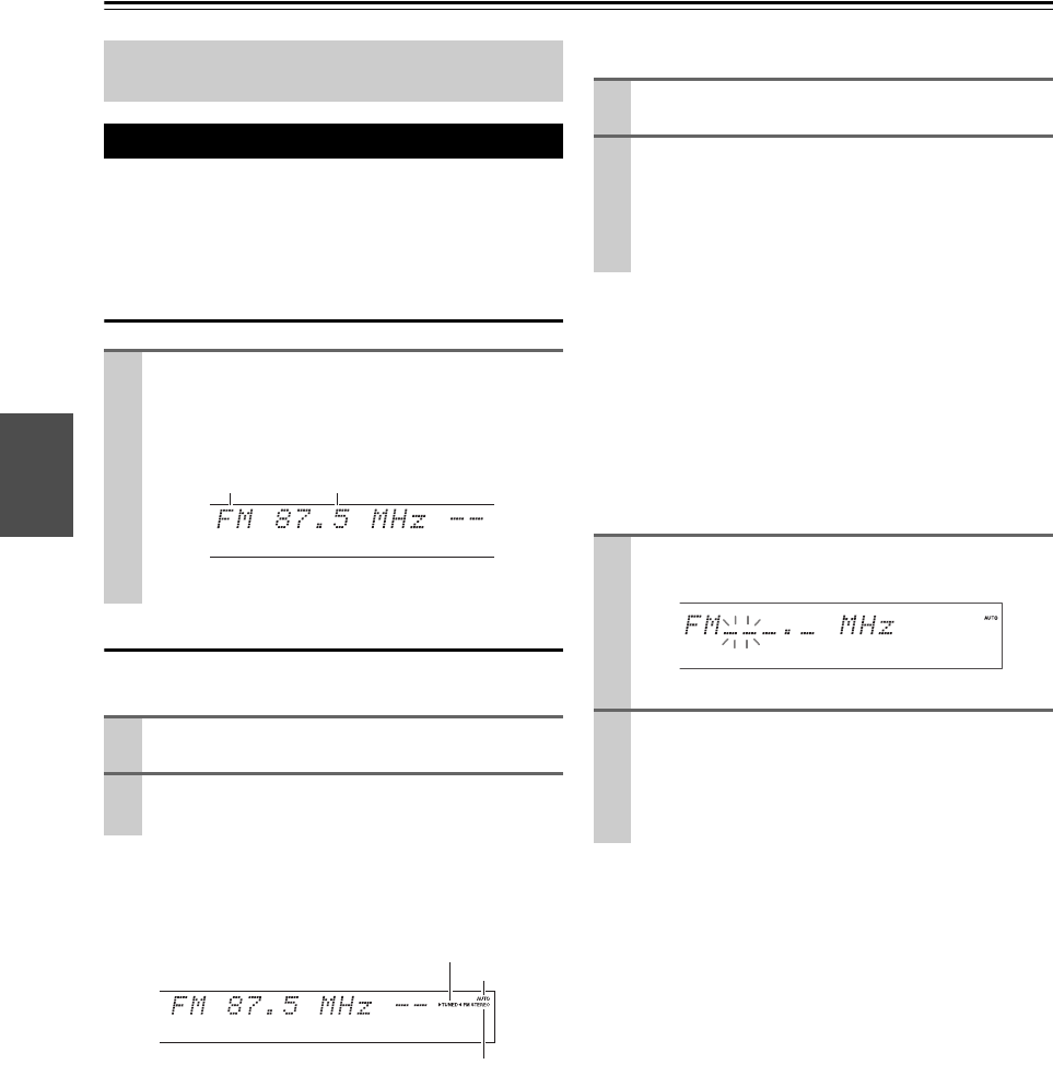
32
En
Listening to the Radio
With the built-in tuner you can enjoy AM and FM radio
stations. You can store your favorite stations as presets for
quick selection.
You can change the frequency steps (➔65).
Listening to the Radio
Tuning into Radio Stations
■Auto tuning mode
When tuned into a station, the TUNED indicator lights.
When tuned into a stereo FM station, the FM STEREO
indicator lights on the display, as shown.
■Manual tuning mode
In manual tuning mode, FM stations will be in mono.
Tuning into weak FM stereo stations
If the signal from a stereo FM station is weak, it may be
impossible to get good reception. In this case, switch to
manual tuning mode and listen to the station in mono.
■Tuning into stations by frequency
You can tune into AM and FM stations directly by enter-
ing the appropriate frequency.
This section describes the procedure using the but-
tons on the front panel unless otherwise specified.
Using the Tuner
Press Tuner to select either “AM” or “FM”.
In this example, FM has been selected.
Each time you press Tuner, the radio band changes
between AM and FM.
(Actual display depends on the country.)
1Press Tuning Mode so that the AUTO indicator
lights on the display.
2Press Tuning q/w.
Searching stops when a station is found.
Band Frequency
TUNED
FM
S
TERE
O
AUTO
1Press Tuning Mode so that the AUTO indicator
goes off on the display.
2Press and hold Tuning q/w.
The frequency stops changing when you release the
button.
Press the buttons repeatedly to change the frequency
one step at a time.
1On the remote controller, press Tuner repeatedly
to select “AM” or “FM”, followed by D.TUN.
(Actual display depends on the country.)
2Within 8 seconds, use the number buttons to enter
the frequency of the radio station.
For example, to tune to 87.5 (FM), press 8, 7, 5.
If you have entered the wrong number, you can retry
after 8 seconds.
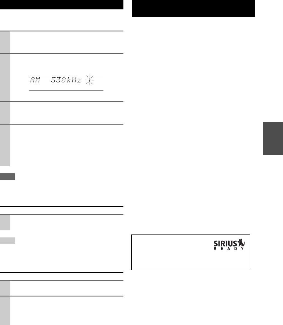
33
En
You can store a combination of up to 40 of your favorite
FM/AM radio stations as presets.
Note
• You can name your radio presets for easy identification (➔61).
Its name is displayed instead of the band and frequency.
Selecting Presets
Tip
• You can also use the remote controller’s number buttons to select
a preset directly.
Deleting Presets
To listen to Satellite Radio, you’ll need to connect a SIR-
IUS Satellite Radio tuner (sold separately) to your Sir-
ius-Ready receiver. SIRIUS Satellite Radio is available to
residents of the US (except Alaska and Hawaii) and Can-
ada.
Satellite Radio delivers a variety of commercial-free
music from categories ranging from Pop, Rock, Country,
R&B, Dance, Jazz, Classical and many more plus cover-
age of all the top professional and college sports including
play by play games from select leagues and teams. Addi-
tional programming includes expert sports talk, uncen-
sored entertainment, comedy, family programming, local
traffic and weather and news from your most trusted
sources.
Once you’ve purchased a SIRIUS tuner you’ll need to
activate it and subscribe to begin enjoying the service.
Easy to follow installation and setup instructions are pro-
vided with the SIRIUS tuner. There are a variety of pro-
gramming packages available, including the option of
adding “The Best of XM” programming to the SIRIUS
service. The Best of XM service is not available to SIR-
IUS Canada subscribers at this time. Please check with
SIRIUS Canada for any updates using the numbers and
web address below.
Family friendly packages are also available to restrict
channels featuring content that may be inappropriate for
children.
To subscribe to SIRIUS, U.S. and Canadian customers can
call 1-888-539-SIRIUS (1-888-539-7474) or
visit sirius.com (US) or siriuscanada.ca (Canada).
Presetting FM/AM Stations
1Tune into the FM/AM station that you want to
store as a preset.
See the previous section.
2Press Memory.
The preset number flashes.
(Actual display depends on the country.)
3While the preset number is flashing (about 8 sec-
onds), use Preset e/r to select a preset from 1
through 40.
4Press Memory again to store the station or chan-
nel.
The station or channel is stored and the preset num-
ber stops flashing.
Repeat this procedure for all of your favorite
FM/AM radio stations.
To select a preset, use Preset e/r on the AV con-
troller, or the remote controller’s CH +/–.
1Select the preset that you want to delete.
See the previous section.
2While holding down Memory, press Tuning
Mode.
The preset is deleted and its number disappears from
the display.
Listening to SIRIUS Satellite Radio®
(North American models)
SIRIUS, XM and all related marks
and logos are trademarks of Sirius
XM Radio Inc. and its subsidiaries.
All rights reserved. Service not available in Alaska and
Hawaii.
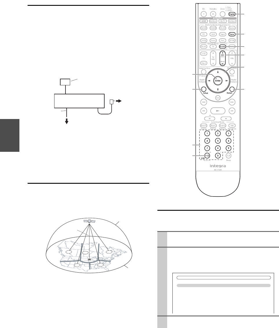
34
En
Setting Up the SiriusConnect™ Home Tuner
The optional SiriusConnect Home tuner kit includes
everything for easy home installation, including the Sirius-
Connect receiver, indoor/outdoor antenna with 21-foot
cable, 8-pin mini DIN connector cable, and an AC power
adapter. See the SiriusConnect Home tuner’s instructions
for more information.
Use the 8-pin mini DIN connector cable to connect the
SiriusConnect receiver to the SIRIUS jack on the rear of
the AV controller.
To use the included antenna indoors, you must place it at a
north-, west-, or east-facing window, depending on where
you live. If this isn’t possible, you’ll need to install it out-
side, away from any overhead obstructions.
Positioning the Antenna
For a consistent satellite signal, the antenna must be posi-
tioned correctly. Use the following map to determine
which area you are in and position the antenna accord-
ingly.
Area 1: Point the antenna toward the sky in the east,
northeast, or southeast, either through a window or out-
side.
Area 2: Point the antenna toward the sky in the north or
northeast, either through a window or outside.
Area 3: Point the antenna toward the sky in the north or
northwest, either through a window or outside.
Area 4: Point the antenna toward the sky in the west,
northwest, or southwest, either through a window or out-
side.
Area 5: Put the antenna outside and point it straight up.
The antenna cannot be used indoors.
Setting the Satellite Radio Mode
Before you can listen to SIRIUS Satellite Radio, you must
set the “SAT Radio Mode” setting to “SIRIUS”.
SiriusConnect
receiver
8-pin mini DIN
connector cable
AC power
Indoor/outdoor antenna
with 21-foot cable
SIRIUS jack on the rear of
the AV controller
1
23
4
5
HORIZON
SKY
SOUTH
WEST EAST
NORTH
1Press Receiver followed by Setup.
The main menu appears onscreen.
2Use q/w to select “Hardware Setup”, and then
press Enter.
The “Hardware Setup” menu appears.
3Use q/w to select “Tuner”, and then press Enter.
Number buttons
Display
Tuner
Receiver
CH +/–
q/w/e/r
Return
D.TUN
Enter
Setup
7. Hardware Setup
1. Remote ID
2. Multi Zone
3. Tuner
4. HDMI
5. Auto Power Down
6. Network
7. Firmware Update
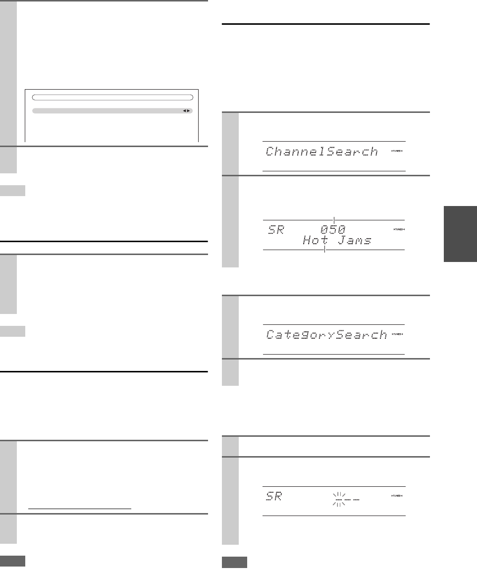
35
En
Tip
• Alternatively, you can use the AV controller’s Setup, arrow but-
tons, and Enter.
Selecting SIRIUS Satellite Radio
Tip
• Alternatively, you can use the AV controller’s Tuner.
Signing Up for SIRIUS Satellite Radio
Before you can use SIRIUS Satellite Radio, you must first
sign up for an account. You’ll need a major credit card and
your SIRIUS Satellite Radio ID, which you can get from
the AV controller, as explained below, or from the Sirius-
Connect Home tuner package.
Note
• Your ID is also displayed on the Satellite Radio screen. See
“Positioning the SiriusConnect Home Antenna” (➔38).
Selecting Channels using the Remote
Controller
There are three ways to select SIRIUS Satellite Radio
channels:
1. Channel Search mode: select any channel.
2. Category Search mode: select channels by category.
3. Direct tuning: enter channel number.
■Channel Search mode
■Category Search mode
■Direct tuning
You can select a SIRIUS Satellite Radio channel directly
by entering its number.
Note
• If you select an unavailable channel, “INVALID CHANNEL”
appears on the display.
• If you select a channel that you are not subscribed to, “CALL
SIRIUS” appears on the display.
• Channels that are locked must be unlocked before you can listen
to them. See “SIRIUS Parental Lock” (➔36) for more informa-
tion.
4Use q/w to select “SAT Radio Mode”, and e/r to
select “SIRIUS”.
Pressing e/r cycles through the following options:
`None:
Select if you’re not using Satellite Radio.
`SIRIUS:
Select to use SIRIUS Satellite Radio.
5When you’ve finished, press Setup.
Setup closes.
Press Tuner repeatedly to select “SIRIUS”.
If “CHECK SIRIUS TUNER” appears on the dis-
play, make sure the SiriusConnect receiver is con-
nected properly. If “ANTENNA ERROR” appears,
make sure the antenna is connected properly.
1Use Tuning q/w on the AV controller to select
channel 0.
Your SIRIUS Satellite Radio ID number is dis-
played. Write it below.
ID
2To sign up, go to: http://activate.siriusradio.com
or call: 1-888-539-SIRIUS (7474)
7–3. Tuner
FM/AM Frequency Step
SAT Radio Mode
Antenna Aiming
SIRIUS Parental Lock
200kHz/10kHz
SIRIUS
1Press Enter repeatedly to select Channel Search
mode.
2Use q/w to select a channel.
You can also use e/r to select a category.
1Press Tuner, and then press Enter repeatedly to
select Category Search mode.
2Use e/r to select a category, and q/w to select a
channel in that category.
1Press D.TUN.
2Within 8 seconds, use the number buttons to enter
the channel number.
For example, to select channel #20, press 0, 2, 0, or
2, 0, Enter.
Channel name
Channel number
36
En
■Selecting the previously selected channel
Selecting Channels on the AV Controller
Presetting Channels
You can store a combination of up to 40 of your favorite
SIRIUS Satellite Radio channels and FM/AM radio sta-
tions as presets.
■Selecting presets
Tip
• You can also use the number buttons to select a preset directly.
■Deleting presets
SIRIUS Parental Lock
With SIRIUS Parental Lock, you can lock out channels
that you do not want to receive and use a 4-digit PIN num-
ber to prevent others from unlocking them.
Press Return to select the previously selected
channel.
1Press Tuner repeatedly to select “SIRIUS”.
2Press Tuning Mode repeatedly to select Channel
Search mode or Category Search mode.
3Press Enter repeatedly to select a category.
4Use Tuning q/w to select a channel.
In Channel Search mode, you can select any channel.
In Category Search mode, you can only select chan-
nels from the currently selected category.
1Tune into the SIRIUS channel that you want to
store as a preset.
2Press Memory on the AV controller.
The preset number flashes.
3While the preset number is flashing (about 8 sec-
onds), use Preset e/r on the AV controller to
select a preset from 1 through 40.
4Press Memory on the AV controller again to store
the channel.
The channel is stored and the preset number stops
flashing.
Repeat this procedure for all of your favorite SIRIUS
Satellite Radio channels.
To select a preset, use Preset e/r on the AV con-
troller or the remote controller’s CH +/–.
1Select the preset that you want to delete.
See the previous section.
2While holding down Memory press Tuning
Mode on the AV controller.
The preset is deleted and its number disappears from
the display.
1Press Receiver followed by Setup.
The main menu appears onscreen.
2Use q/w to select “Hardware Setup”, and then
press Enter.
The “Hardware Setup” menu appears.
3Use q/w to select “Tuner”, and then press Enter.
4Use q/w to select “SIRIUS Parental Lock”, and
then press Enter.
The following screen appears.
Note
•If the “SAT Radio Mode” is set to “None” (➔34), the
“SIRIUS Parental Lock” setting is not available.
5Use e/r to select a number on the screen, and
then press Enter.
Repeat this for each of the four digits in the PIN
number.
If you’re entering the PIN number for the very first
time, the default is “0000”. The following screen
appears.
If you’ve already set a PIN number, you must enter
the correct PIN to get to this screen. If you enter the
wrong PIN, the message “Wrong Code!” appears
and you’ll have to enter the PIN again.
Note
•The “SIRIUS Parental Lock” setting cannot be set unless
the AV controller and the SiriusConnect receiver are con-
nected.
7. Hardware Setup
1. Remote ID
2. Multi Zone
3. Tuner
4. HDMI
5. Auto Power Down
6. Network
7. Firmware Update
SIRIUS Parental Lock
Enter Code
01 2 3 4 5 6 7 8 9
SIRIUS Parental Lock
Edit Code
Parental Lock
37
En
Note
• You can temporarily release the parental lock by selecting the
locked channel directly by entering the number (Direct tuning)
or selecting the preset.
• To unlock a channel, you must enter the correct PIN number and
change it to Unlocked in step 6.
Tip
• Alternatively, you can use the AV controller’s Setup, arrow but-
tons, and Enter.
Changing the PIN Number
6Use q/w to select “Parental Lock”, and then press
Enter.
The channel number, channel name, and the current
status are displayed.
7Use q/w to select a channel, and e/r to select
“Locked” or “Unlocked”.
8Press Enter to save your changes, or press Return
to return to the previous screen without saving.
When Enter is pressed, the confirmation message
“Locked” or “Unlocked” appears.
9Press Setup.
Setup closes.
1Press Receiver followed by Setup.
The main menu appears onscreen.
2Use q/w to select “Hardware Setup”, and then
press Enter.
The “Hardware Setup” menu appears.
3Use q/w to select “Tuner”, and then press Enter.
4Use q/w to select “SIRIUS Parental Lock”, and
then press Enter.
The following screen appears.
Note
• If the “SAT Radio Mode” is set to “None” (➔34), the
“SIRIUS Parental Lock” setting is not available.
7. Hardware Setup
1. Remote ID
2. Multi Zone
3. Tuner
4. HDMI
5. Auto Power Down
6. Network
7. Firmware Update
SIRIUS Parental Lock
Enter Code
01 2 3 4 5 6 7 8 9
5Use e/r to select a number on the screen, and
then press Enter.
Repeat this for each of the four digits in the PIN
number.
If you’re entering the PIN number for the very first
time, the default is “0000”. The following screen
appears.
If you’ve already set a PIN number, you must enter
the correct PIN to get to this screen. If you enter the
wrong PIN, the message “Wrong Code!” appears
and you’ll have to enter the PIN again.
Note
•The “SIRIUS Parental Lock” setting cannot be set unless
the AV controller and the SiriusConnect receiver are con-
nected.
6Use q/w to select “Edit Code”, and then press
Enter.
The following screen appears.
7Use e/r to select a number on the screen, and
then press Enter.
Repeat this for each of the four digits in the new
PIN number.
The following screen appears.
8Confirm the new PIN number by entering it again.
If you confirm the PIN number correctly, the new
PIN is saved and the message “Complete” appears.
If you confirm the PIN number incorrectly, “Wrong
Code!” appears, and you’ll be returned to step 5 to
try again.
9Press Setup.
Setup closes.
SIRIUS Parental Lock
Edit Code
Parental Lock
SIRIUS Parental Lock
New Code
01 2 3 4 5 6 7 8 9
SIRIUS Parental Lock
Confirm
01 2 3 4 5 6 7 8 9
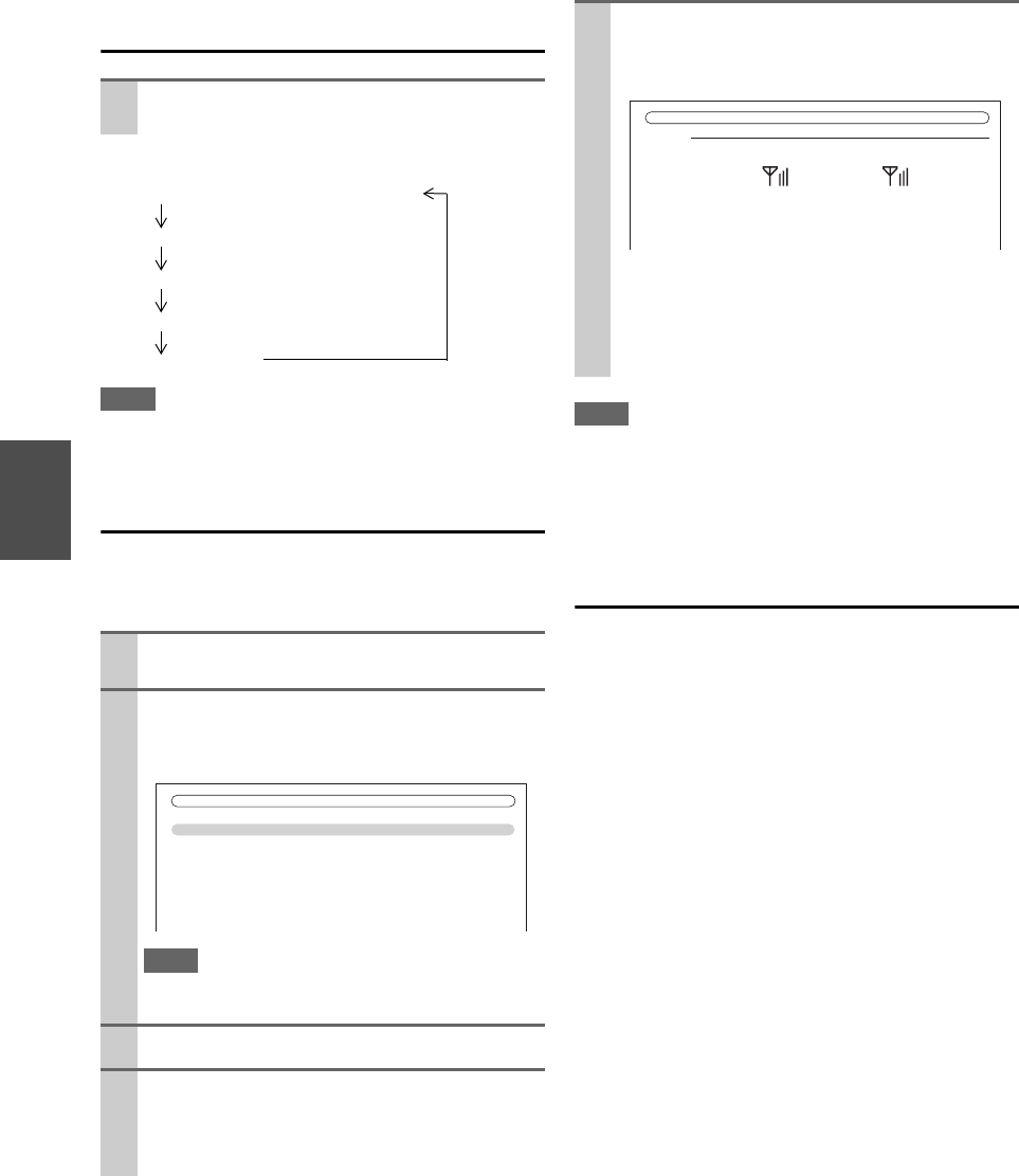
38
En
Displaying SIRIUS Satellite Radio
Information
The following information can be displayed:
Note
• If the category, artist/composer, or song title is not available,
“---” will be displayed instead.
Positioning the SiriusConnect Home
Antenna
You can check the strength of the SIRIUS Satellite Radio
signal and adjust the position of the SiriusConnect Home
antenna accordingly.
Note
• So long as the signal strength is good, you can enjoy SIRIUS
Satellite Radio by using either satellite or terrestrial reception.
• Terrestrial signals are only available in certain areas.
• The SIRIUS information on the Satellite Radio screen is only
displayed when the “SAT Radio Mode” setting is set to “SIR-
IUS” (➔34).
SIRIUS Satellite Radio Messages
The following messages may appear while using SIRIUS
Satellite Radio.
■ACQUIRING SIGNAL
The SiriusConnect receiver is acquiring the signal or no
signal is present. Make sure the SiriusConnect Home
tuner is connected properly and that there are no obsta-
cles nearby.
■ANTENNA ERROR
Make sure the SiriusConnect Home tuner is connected
properly.
■SUBSCRIPTION UPDATED
Displayed while your subscription is being updated. No
operations can be performed until this message has
cleared.
■UPDATING CHANNELS XXX%
Displayed while the channel map is being updated. Wait
until the updating is complete.
■SIRIUS UPDATING
Displayed while the SiriusConnect receiver’s firmware
is being updated.
■INVALID CHANNEL
Displayed if you select an unavailable channel.
■CALL SIRIUS
Displayed when you select a channel to which you are
not subscribed. Call SIRIUS if you want to subscribe.
■CHECK SIRIUS TUNER
Displayed if the SiriusConnect receiver is not con-
nected. Make sure the SiriusConnect receiver is con-
nected properly, and make sure its AC adapter is
plugged in.
Press Display repeatedly to cycle through the
available information.
1Press Receiver followed by Tuner, and Setup.
The main menu appears onscreen.
2Use q/w to select “Hardware Setup”, and then
press Enter.
The “Hardware Setup” menu appears.
Note
•If the “SAT Radio Mode” setting is set to “None”
(➔34), the “Antenna Aiming” setting is not available.
3Use q/w to select “Tuner”, and then press Enter.
4Use q/w to select “Antenna Aiming”, and then
press Enter.
The signal strength meter and your SIRIUS Satellite
Radio ID are displayed.
Category
Artist/composer
Song title
Listening mode
Ch
anne
l
name an
d
Ch
anne
l
num
b
er
7. Hardware Setup
1. Remote ID
2. Multi Zone
3. Tuner
4. HDMI
5. Auto Power Down
6. Network
7. Firmware Update
5Position the SiriusConnect Home antenna so that
as many bars as possible (up to 3) appear on the
Satellite signal strength meter.
If you cannot receive a satellite signal, position the
SiriusConnect Home antenna so that as many bars as
possible (up to 3) appear on the Terrestrial signal
strength meter.
SiriusID
112233445566
Satellite Terrestrial
SIRIUS
Antenna Aiming

39
En
When tuned into an RDS station, the RDS indicator lights.
What is RDS?
RDS stands for Radio Data System and is a method of
transmitting data in FM radio signals. It was developed by
the European Broadcasting Union (EBU) and is available
in most European countries. Many FM stations use it these
days. In addition to displaying text information, RDS can
also help you find radio stations by type (e.g., news, sport,
rock, etc.).
The AV controller supports four types of RDS informa-
tion:
■PS (Program Service)
When tuned to an RDS station that’s broadcasting PS
information, the station’s name will be displayed. Press-
ing Display will display the frequency for 3 seconds.
■RT (Radio Text)
When tuned to an RDS station that’s broadcasting text
information, the text will be shown on the display as
described in the next section.
■PTY (Program Type)
This allows you to search for RDS radio stations by type
(➔39).
■TP (Traffic Program)
This allows you to search for RDS radio stations that
broadcast traffic information (➔39).
Note
• In some cases, the text characters displayed on the AV controller
may not be identical to those broadcast by the radio station. Also,
unexpected characters may be displayed when unsupported
characters are received. This is not a malfunction.
• If the signal from an RDS station is weak, RDS data may be
displayed intermittently or not at all.
When tuned to an RDS station that’s broadcasting text
information, the text can be displayed.
Displaying Radio Text (RT)
Note
• The message “Waiting” may appear while the AV controller
waits for the RT information.
• If the message “No Text Data” appears on the display, no RT
information is available.
Finding Stations by Type (PTY)
You can search for radio stations by type.
Listening to Traffic News (TP)
You can search for stations that broadcast traffic news.
Using RDS (Australian models)
RDS works only in areas where RDS broadcasts are
available.
Press RT/PTY/TP once.
The RT information scrolls across the display.
1Press RT/PTY/TP twice.
The current program type appears on the display.
2Use Preset e/r to select the type of program you
want.
See the table shown later in this chapter.
3To start the search, press Enter.
The AV controller searches until it finds a station of
the type you specified, at which point it stops briefly
before continuing with the search.
4When a station you want to listen to is found, press
Enter.
If no stations are found, the message “Not Found”
appears.
1Press RT/PTY/TP three times.
If the current radio station is broadcasting TP (Traf-
fic Program), “[TP]” will appear on the display, and
traffic news will be heard as and when it’s broadcast.
If “TP” without square brackets appears, this means
that the station is not broadcasting TP.
2To locate a station that is broadcasting TP, press
Enter.
The AV controller searches until it finds a station
that’s broadcasting TP.
If no stations are found, the message “Not Found”
appears.

40
En
■RDS program types (PTY)
Type Display
None None
News reports News
Current affairs Affairs
Information Info
Sport Sport
Education Educate
Drama Drama
Culture Culture
Science and technology Science
Varied Varie d
Pop music Pop M
Rock music Rock M
Middle of the road music Easy M
Light classics Light M
Serious classics Classics
Other music Other M
Weather Weather
Finance Finance
Children’s programmes Children
Social affairs Social
Religion Religion
Phone in Phone In
Travel Travel
Leisure Leisure
Jazz music Jazz
Country music Country
National music Nation M
Oldies music Oldies
Folk music Folk M
Documentary Document
Alarm test TEST
Alarm Alarm!
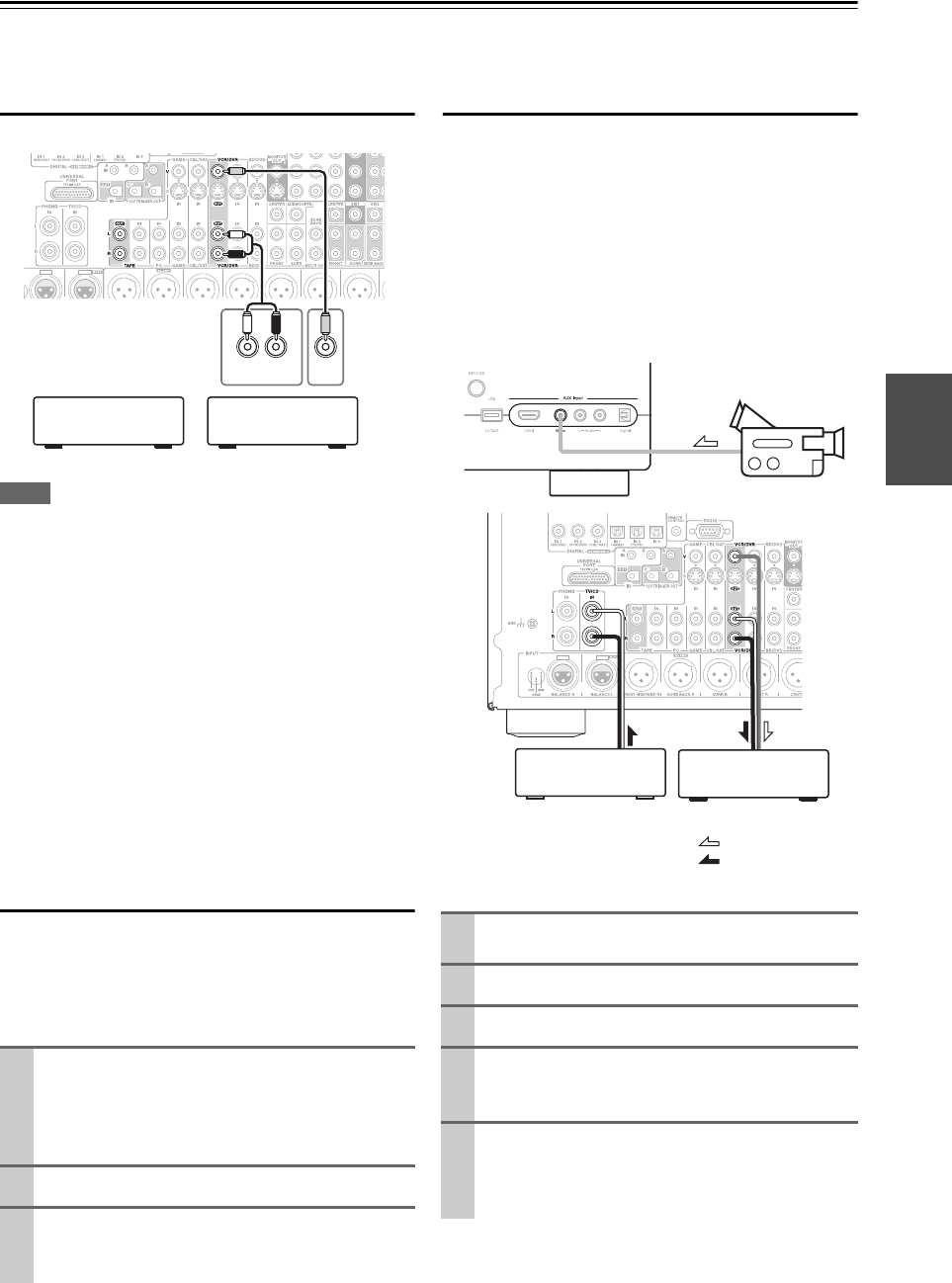
41
En
Recording
This section explains how to record the selected input source to a component with recording capability, and how to record
audio and video from different sources.
Connecting a Recording Component
Note
• The AV controller must be turned on for recording. Recording is
not possible while it’s in Standby mode.
• If you want to record directly from your TV or playback VCR to
the recording VCR without going through the AV controller,
connect the TV/VCR’s audio and video outputs directly to the
recording VCR’s audio and video inputs. See the manuals sup-
plied with your TV and VCR for details.
• Video signals connected to composite video inputs can be
recorded only via composite video outputs. If your TV/VCR is
connected to a composite video input, the recording VCR must
be connected to a composite video output.
• The surround sound and DSP listening modes cannot be
recorded.
• Copy-protected Blu-ray Disc/DVDs cannot be recorded.
• Sources connected to a digital input cannot be recorded. Only
analog inputs can be recorded.
• DTS signals will be recorded as noise, so don’t attempt analog
recording of DTS CDs or LDs.
AV Recording
Audio sources can be recorded to a recorder (e.g., cassette
deck, CDR, MD) connected to the VCR/DVR OUT or
TAPE OUT jacks. Video sources can be recorded to a
video recorder (e.g., VCR, DVD recorder) connected to
the VCR/DVR OUT jack.
Recording Separate AV Sources
Here you can record audio and video from completely
separate sources, allowing you to overdub audio onto your
video recordings. This function takes advantage of the fact
that when an audio-only input source (TV/CD, Phono,
etc.) is selected, the video input source remains
unchanged.
In the following example, audio from the CD player con-
nected to the TV/CD IN and video from the camcorder
connected to the AUX Input Video jack are recorded by
the VCR connected to the VCR/DVR OUT jacks.
1Use the input selector buttons to select the source
that you want to record.
You can watch the source while recording. The AV
controller’s Master Volume control has no effect
on recording.
2On your recorder, start recording.
3On the source component, start playback.
If you select another input source during recording,
that input source will be recorded.
AUDIO
IN
LR
VIDEO
IN
Cassette, CDR, MD,
etc.
VCR, DVD recorder
1Prepare the camcorder and CD player for play-
back.
2Prepare the VCR for recording.
3Press AUX input selector.
4Press TV/CD input selector.
This selects the CD player as the audio source, but
leaves the camcorder as the video source.
5Start recording on the VCR and start playback on
the camcorder and CD player.
The video from the camcorder and the audio from
the CD player are recorded by the VCR.
Camcorder
VCRCD player
: Video signal
: Audio signal
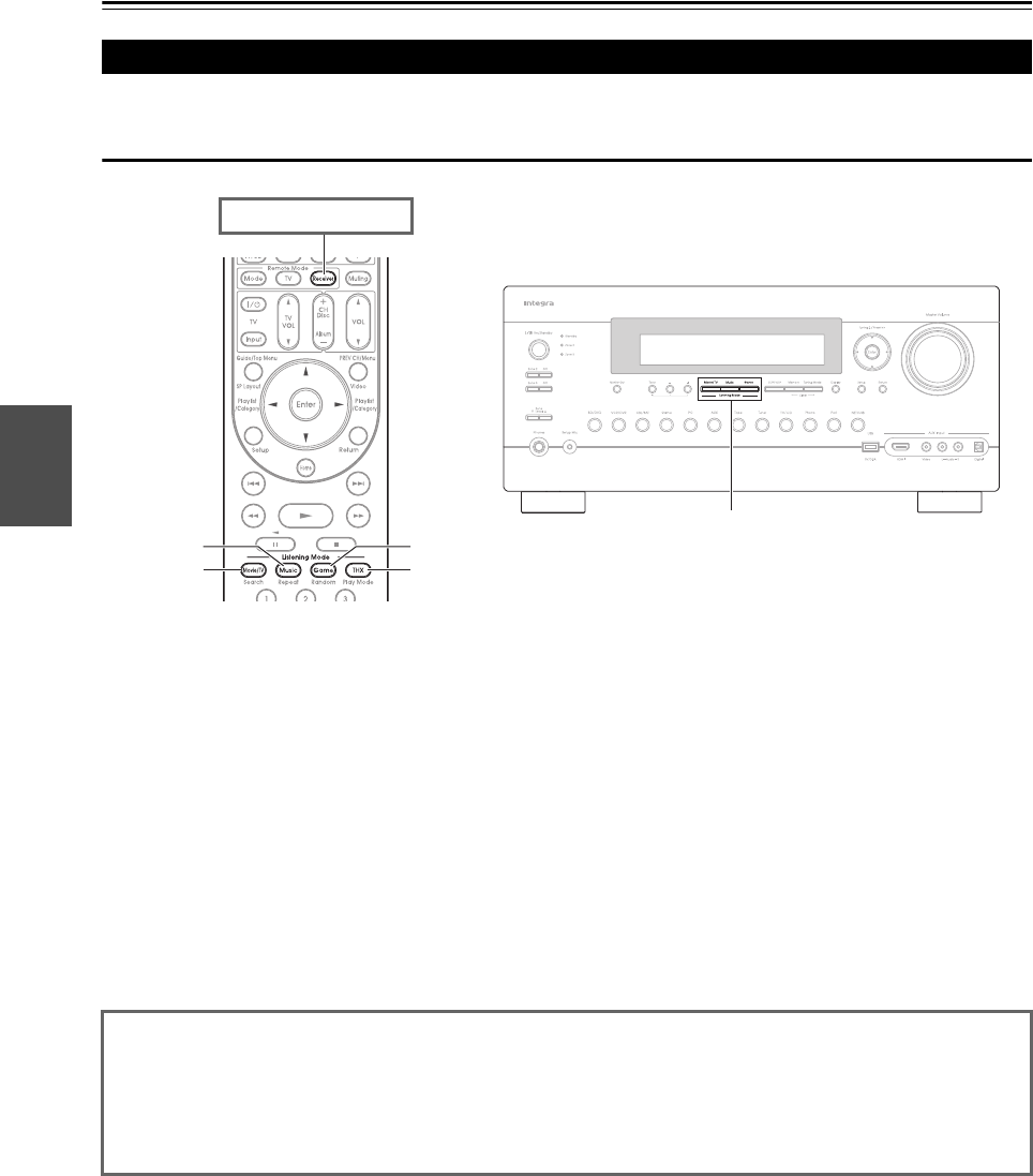
42
En
Using the Listening Modes
See “About Listening Modes” for detailed information about the listening modes (➔43).
Listening Mode Buttons
Movie/TV button
This button selects the listening modes intended for use
with movies and TV.
Music button
This button selects the listening modes intended for use
with music.
Game button
This button selects the listening modes intended for use
with video games.
THX button
This button selects the THX listening modes.
Selecting Listening Modes
Game
THX
Movie/TV
Music
Press Receiver first.
Movie/TV, Music, Game
• The Dolby Digital and DTS listening modes can only be selected if your Blu-ray Disc/DVD player is connected to the AV
controller with a digital audio connection (coaxial, optical, or HDMI).
• The listening modes you can select depend on the format of the input signal. To check the format, see “Displaying Source
Information” (➔26).
• While a pair of headphones is connected, you can select the following listening modes: Mono, Direct, and Stereo.
• The listening modes cannot be used while you are listening to sound through your TV speakers coming from components
connected to the AV controller (“TV Sp On” appears on the front panel).
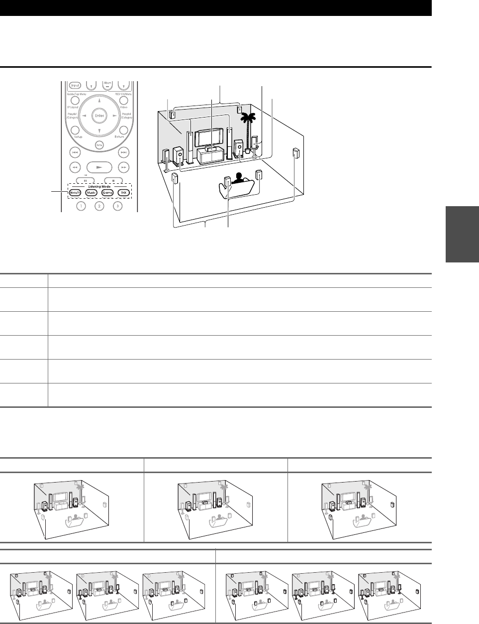
43
En
The AV controller’s listening modes can transform your listening room into a movie theater or concert hall, with high
fidelity and stunning surround sound.
Explanatory Notes
■Input Source
The following audio formats are supported by the listening mode.
■Speaker Layout
The illustration shows which speakers are activated in each channel. See “Speaker Configuration” for the speaker setup
(➔54).
About Listening Modes
AThis is mono (monophonic) sound.
SThis is stereo (stereophonic) sound. Two independent audio signal channels are reproduced through two
speakers.
DThis is 5.1-channel surround sound. This surround system has five main channels of sound and a sixth sub-
woofer channel (called the point-one channel).
FThis is 7.1-channel surround sound. This is a further sound enhancement to 5.1 channel sound with two
additional speakers that provide greater sound envelopment and more accurate positioning of sounds.
GThis is DTS-ES surround sound. This surround system can produce a discrete or a matrix-encoded sixth
channel from existing DTS 5.1 encoded material.
HThis is Dolby Digital EX surround sound. This provides a center back surround channel from 5.1-channel
sources.
zxc
nm
Listening
Mode
ij
gh
kl
cb
af
de
abFront speakers
cCenter speaker
deSurround speakers
fSubwoofer(s)
ghSurround back speakers
ijFront high speakers
klFront wide speakers
44
En
Listening Modes
Listening Mode Description Input
Source
Speaker
Layout
Direct In this mode, audio from the input source is output without surround-sound
processing. The speaker configuration (presence of speakers), speaker dis-
tances and A/V Sync settings are enabled, but much of the processing set via
Home is disabled. See “Advanced Setup” for more details (➔49).
A
S
D
F
G
H
zxc
n*1 m*1
Stereo Sound is output by the front left and right speakers and subwoofer. A
S
D
F
G
H
zxc
nm
Mono Use this mode when watching an old movie with a mono soundtrack, or use
it with the foreign language soundtracks recorded in the left and right chan-
nels of some movies. It can also be used with DVDs or other sources contain-
ing multiplexed audio, such as karaoke DVDs.
Multichannel This mode is for use with PCM multichannel sources. D
F
xcn
m
Dolby Pro Logic IIx
Dolby Pro Logic II
Dolby Pro Logic IIx expands any 2-channel source for 7.1-channel play-
back. It provides a very natural and seamless surround-sound experience that
fully envelops the listener. As well as music and movies, video games can
also benefit from the dramatic spatial effects and vivid imaging. If you’re not
using any surround back speakers, Dolby Pro Logic II will be used instead
of Dolby Pro Logic IIx.
• Dolby PLIIx Movie
Use this mode with any stereo or Dolby Surround (Pro Logic) movie (e.g.,
TV, DVD, VHS).
• Dolby PLIIx Music
Use this mode with any stereo or Dolby Surround (Pro Logic) music source
(e.g., CD, radio, cassette, TV, VHS, DVD).
• Dolby PLIIx Game
Use this mode with video games, especially those that bear the Dolby Pro
Logic II logo.
Sxcn
m
•Dolby PLIIx Movie and Dolby PLIIx Music
These modes use the Dolby Pro Logic IIx modes to expand 5.1-channel
sources for 7.1-channel playback.
Dnm
Dolby Pro Logic IIz
Height
Dolby Pro Logic IIz Height is designed to more effectively use existing
program material when height channel speaker outputs are present. Dolby
Pro Logic IIz Height can be used to upmix a variety of sources from movies
and music, but are particularly well-suited to upmix game content.
S
D
F
n*2 m*3
Dolby EX These modes expand 5.1-channel sources for 6.1/7.1-channel playback.
They’re especially suited to Dolby EX soundtracks that include a
matrix-encoded surround back channel. The additional channel adds an extra
dimension and provides an enveloping surround sound experience, perfect
for rotating and fly-by sound effects.
D
H
n*4 m*4
Dolby Digital In this mode, audio from the input source is output without surround-sound
processing. The speaker configuration (presence of speakers), crossover fre-
quencies, speaker distances, A/V Sync and much of the processing set via
Home are enabled. See “Advanced Setup” for more details (➔49).
Dxcn
m
Dolby Digital Plus*5 Dxcn
m
Fxcn
*1
m*1
Dolby TrueHD Dxcn
m
Fxcn
*1
m*1
DTS Dxcn
m
Di rectdioPPoPP
StereodioPPoPP
Monoeod i oPPoPP
MultichioPPoPP
PL bMo v i ePP PP
PL bMu s i cPP PP
PL bGame cPPcPP
PL xGMo v i ePP
PL xGMusicPP
PL xGGame cP cP
PL zGHe i gh t
DolbycEXoPPoPP
DolbycDiEXPP
DolbycDioPPoPP
DolbycDoPPoPP
+
DD lTeHDPPPPPPru
DTS d
d
i o P P o P P
45
En
DTS-HD High
Resolution Audio
(Continued from the previous page.) D xcn
m
F xcn*1
m*1
DTS-HD Master
Audio
D xcn
F xcn*1
m*1
DTS Express S
D
xcn
m
DSD*6 D xcn
m
DTS 96/24*7 This mode is for use with DTS 96/24 sources. This is high-resolution DTS
with a 96 kHz sampling rate and 24-bit resolution, providing superior fidel-
ity. Use it with DVDs that bear the DTS 96/24 logo.
D xcn
m
DTS-ES Discrete*8 This mode is for use with DTS-ES Discrete soundtracks, which use a dis-
crete surround back channel for true 6.1/7.1-channel playback. The seven
totally separate audio channels provide better spatial imaging and
360-degree sound localization, perfect for sounds that pan across the sur-
round channels. Use it with DVDs that bear the DTS-ES logo, especially
those with a DTS-ES Discrete soundtrack.
Gn
*4 m*4
DTS-ES Matrix*8 This mode is for use with DTS-ES Matrix soundtracks, which use a
matrix-encoded back-channel for 6.1/7.1-channel playback. Use it with
DVDs that bear the DTS-ES logo, especially those with a DTS-ES Matrix
soundtrack.
Gn
*4 m*4
DTS Neo:6 This mode expands any 2-channel source for up to 7.1-channel playback. It
uses seven full-bandwidth channels of matrix decoding for matrix-encoded
material, providing a very natural and seamless surround sound experience
that fully envelops the listener.
•Neo:6 Cinema
Use this mode with any stereo movie (e.g., TV, DVD, VHS).
•Neo:6 Music
Use this mode with any stereo music source (e.g., CD, radio, cassette, TV,
VHS, DVD).
S xcn
m
This mode uses Neo:6 to expand 5.1-channel sources for 6.1/7.1-channel
playback.
Dn
*4 m*4
Audyssey DSX*9 Audyssey DSX™ is a scalable system that adds new speakers to improve
surround impression. Starting with a 5.1 system Audyssey DSX first adds
Wide channels for the biggest impact on envelopment. Research in human
hearing has proven that information from the Wide channels is much more
critical in the presentation of a realistic soundstage than Back Surround
channels found in traditional 7.1 systems. Audyssey DSX then creates a pair
of Height channels to reproduce the next most important acoustical and per-
ceptual cues. In addition to these new Wide and Height channels,
Audyssey DSX applies Surround Envelopment Processing to enhance the
blend between the front and surround channels.
D
F
G
nm
The combination of Dolby Pro Logic II/IIx and Audyssey DSX modes can
be used.
S
D
F
G
nm
The combination of Neo:6 and Audyssey DSX mode can be used. Dnm
The combination of Neo:6 Cinema/Music and Audyssey DSX modes can
be used.
Snm
The combination of Dolby EX and Audyssey DSX modes can be used. D
F
G
nm
Listening Mode Description Input
Source
Speaker
Layout
DTS–HD HR
DTS–HD MSTR
DTS Ex p r e s s
DSD
DTSe
e
96 / 24PP PP
ESSDiscrete
ESSMa t r i x te te
Neo:6trixtexte
Neo:6trixtexteNeo:6 Cinema
Neo:6tMu s i c
Audys sey DSX
PL Mo v ieDSXx
PL xMusicDSX
PL bMo v ieDSX
PL bMu s icDSX
PL bGameDSX
Neo:6trixtexteNeo:6 DSX
Neo:6trixtexteNeo:6 Cin DSX
Neo:6tMusDSX
Dolby EXDSX
46
En
THX Founded by George Lucas, THX develops stringent standards that ensure
movies are reproduced in movie theaters and home theaters just as the direc-
tor intended. THX Modes carefully optimize the tonal and spatial character-
istics of the soundtrack for reproduction in the home-theater environment.
They can be used with 2-channel matrixed and multichannel sources. Sur-
round back speaker output depends on the source material and the selected
listening mode.
•THX Cinema
THX Cinema mode corrects theatrical soundtracks for playback in a home
theater environment. In this mode, THX Loudness Plus is configured for
cinema levels and Re-EQ, Timbre Matching, and Adaptive Decorrelation
are active.
•THX Music
THX Music mode is tailored for listening to music, which is typically mas-
tered at significantly higher levels than movies. In this mode, THX Loud-
ness Plus is configured for music playback and only Timbre Matching is
active.
• THX Games
THX Games mode is meant for spatially accurate playback of game audio,
which is often mixed similarly to movies but in a smaller environment. THX
Loudness Plus is configured for game audio levels, with Timbre Matching
active.
D
F
G
cnm
The combination of Dolby Pro Logic II/IIx and THX Cin-
ema/Music/Games modes can be used.
S
D
H
cnm
The combination of Dolby Pro Logic IIz Height*2 and THX Cin-
ema/Music/Games modes can be used.
S
D
F
G
H
nm
The combination of DTS Neo:6 and THX Cinema/Music/Games modes
can be used.
S
D
F
H
cnm
• THX Ultra2 Cinema
This mode expands 5.1-channel sources for 7.1- channel playback. It does
this by analyzing the composition of the surround source, optimizing the
ambient and directional sounds to produce the surround back channel out-
put.
•THX Ultra2 Music
This mode is designed for use with music. It expands 5.1-channel sources
for 7.1-channel playback.
•THX Ultra2 Games
This mode is designed for use with video games. It can expand 5.1-channel
sources for 6.1/7.1-channel playback.
• THX Surround EX
This mode expands 5.1-channel sources for 6.1/7.1- channel playback. It’s
especially suited to Dolby Digital EX sources. THX Surround EX, also
known as Dolby Digital Surround EX, is a joint development between
Dolby Laboratories and THX Ltd.
D
F
nm
The combination of Dolby Pro Logic IIz Height*4 and THX Ultra2 Cin-
ema/Music/Games modes can be used.
S
D
F
G
H
Listening Mode Description Input
Source
Speaker
Layout
THX C i n ema
Neo:6trixtexteTHX Mu s i c
THX Game s
Neo:6trixtexteTHX U2 C iCnema
THXU2Music
THX U2 Game s
THX Su r r EX

47
En
Neural Surround*4 This mode employs psychoacoustic frequency domain processing, which
allows delivery of a more detailed sound stage, with superior channel separa-
tion and localization of audio elements. The Neural Surround modes can
expand any 2-channel stereo source for 5.1- or 7.1-channel playback, respec-
tively. Use them with CD, radio, cassette, TV, VHS, DVD, and other 2-chan-
nel stereo sources, including video games. Neural Surround can also be used
by broadcasters to encode and transmit surround-sound content over a stereo
signal, which listeners can enjoy as either surround sound or normal stereo.
S xcn
m
Dnm
The combination of Neural Surround and THX Cinema/Music/Games
modes can be used.
S xcn
m
Dnm
Neural Digital
Music*4
This is a new surround mode specifically designed to enhance the playback
of compressed digital music content. It provides listeners with an expanded
sound stage and clean surround experience, even with compressed audio
sources such as MP3s and Internet streams.
S xcn
m
Listening Mode Description Input
Source
Speaker
Layout
NRL Su r round
NRL THXCinema
NRL THXMus ic
NRL -THXGames
NRL -Di gMus ic
48
En
Onkyo-Original DSP Listening Modes
Note
*1 Based on the audio channels contained in the source, the corresponding speakers will output the sound.
*2 Surround back and front wide speakers are not supported.
*3 Front wide speakers are not supported.
*4 Front high and front wide speakers are not supported.
*5 For the Blu-ray Discs, Dolby Digital is used in a 3.1/5.1-channel speaker system.
*6 AV controller can input the DSD signal from HDMI IN. Setting the output setting on the player side to PCM might obtain a better
sound according to the player. In that case, set the output setting on the player side to PCM.
*7 DTS is used depending on the configuration of the AV controller (e.g., Audyssey Dynamic EQ® is on).
*8 If there are no surround back speakers, DTS is used.
*9 This listening mode can be selected only when all the following conditions are satisfied:
a. Center speaker is connected to the power amplifier.
b. Either of front high or front wide speakers is connected to the power amplifier.
• The listening modes cannot be selected with some source formats.
Listening Mode Description Input
Source
Speaker
Layout
Orchestra Suitable for classical or operatic music, this mode emphasizes the surround
channels in order to widen the stereo image, and simulates the natural rever-
beration of a large hall.
A
S
D
F
G
H
cnm
Unplugged Suitable for acoustic instruments, vocals, and jazz, this mode emphasizes the
front stereo image, giving the impression of being right in front of the stage.
Studio-Mix Suitable for rock or pop music, listening to music in this mode creates a
lively sound field with a powerful acoustic image, like being at a club or rock
concert.
TV Logic This mode adds realistic acoustics to TV shows produced in a TV studio,
surround effects to the entire sound, and clarity to voices.
Game-RPG In this mode, the sound has a dramatic feel with a similar atmosphere to
Orchestra mode.
Game-Action In this mode, sound localization is distinct with emphasis on bass.
Game-Rock In this mode, sound pressure is emphasized to heighten live feel.
Game-Sports In this mode, reverberation is increased and sound localization decreased
slightly.
All Ch Stereo Ideal for background music, this mode fills the entire listening area with ste-
reo sound from the front, surround, and surround back speakers.
xcn
m
Full Mono In this mode, all speakers output the same sound in mono, so the sound you
hear is the same regardless of where you are within the listening room.
T-D (Theater-
Dimensional)
With this mode you can enjoy a virtual surround sound even with only two or
three speakers. This works by controlling how sounds reach the listener’s left
and right ears. Good results may not be possible if there’s too much reverb,
so we recommend that you use this mode in an environment with little or no
natural reverb.
zxc
nm
Or ches t ra
Unp l ugged
Studio–Mix
TV Lo g i c
Game –RPG
Game – Ac t i o n
Game –Ro c k
Game – Sp o r t s
Al l Ch Stereo
Fu l l Mono
T–D
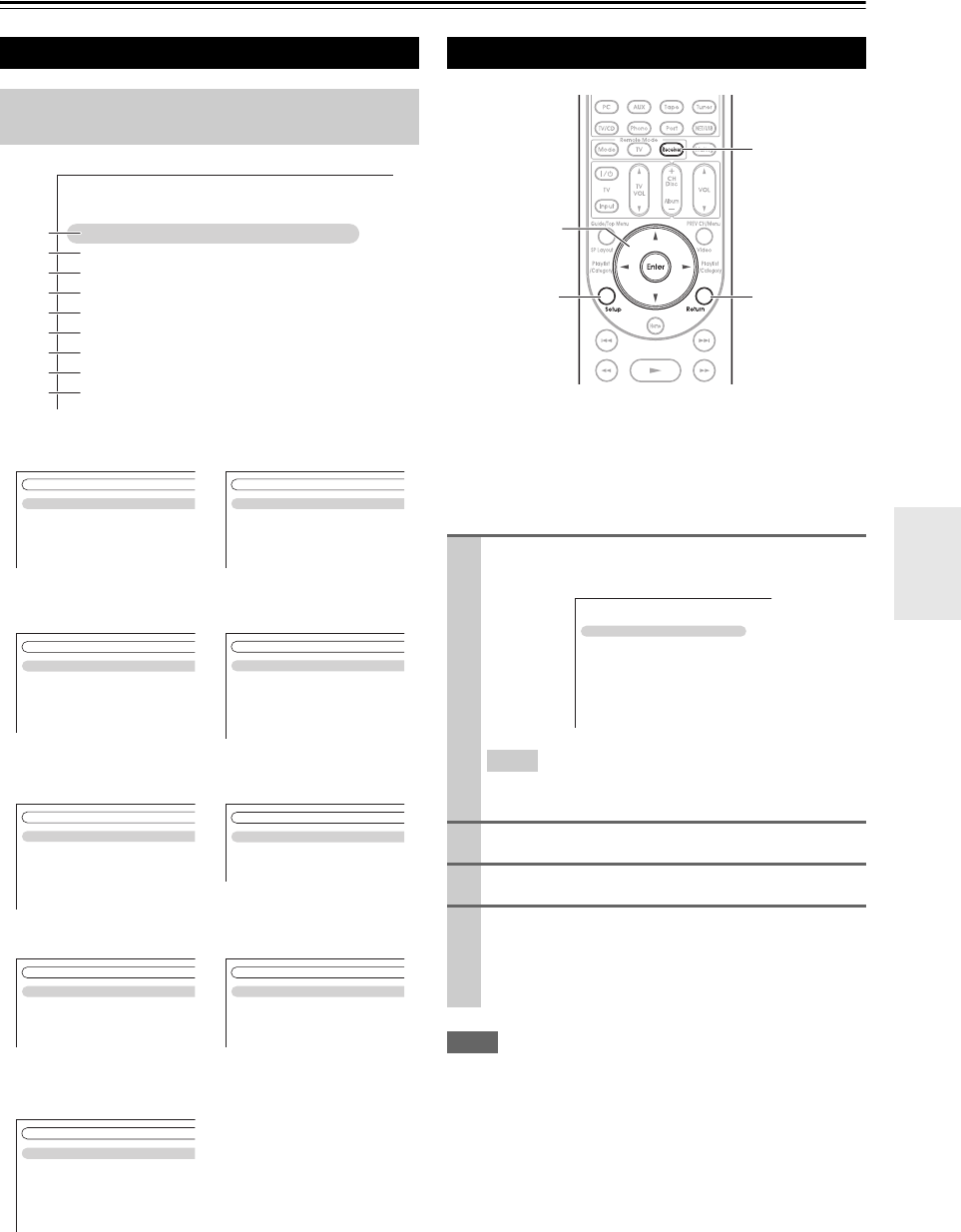
49
En
Advanced Operations
Advanced Setup
The on-screen setup menus appear on the connected TV
and provide a convenient way to change the AV control-
ler’s various settings. Settings are organized into 9 catego-
ries on the main menu.
Carry out the settings by using the on-screen display.
Note
• This procedure can also be performed on the AV controller by
using Setup, arrow buttons, and Enter.
• During Audyssey MultEQ®XT32 Room Correction and
Speaker Setup, messages, etc., that are displayed on the TV
screen will appear in the Display.
On-screen Setup Menus
This manual describes the procedure using the
remote controller unless otherwise specified.
aInput/Output Assign
(➔50)
fMiscellaneous
(➔64)
bSpeaker Setup
(➔54)
gHardware Setup
(➔65)
cAudio Adjust
(➔57)
hRemote Controller
Setup (➔92, 97)
dSource Setup (➔59)iLock Setup (➔68)
eListening Mode Preset
(➔64)
MENU
1. Input/Output Assign
2. Speaker Setup
3. Audio Adjust
4. Source Setup
5. Listening Mode Preset
6. Miscellaneous
7. Hardware Setup
8. Remote Controller Setup
9. Lock Setup
a
b
c
d
e
f
g
h
i
1. Monitor Out
2. HDMI Input
3. Component Video Input
4. Digital Audio Input
5. Analog Audio Input
1. Input/Output Assign
1. Volume Setup
2. OSD Setup
3. 12V Trigger A Setup
4. 12V Trigger B Setup
5. 12V Trigger C Setup
6. Miscellaneous
1. Speaker Settings
2. Speaker Configuration
3. Speaker Distance
4. Level Calibration
5. Equalizer Settings
6. THX Audio Setup
2. Speaker Setup
1. Remote ID
2. Multi Zone
3. Tuner
4. HDMI
5. Auto Power Down
6. Network
7. Firmware Update
7. Hardware Setup
1. Multiplex/Mono
2. Dolby
3. DTS
4. Audyssey DSX
5. Theater-Dimensional
6. LFE Level
7. Direct
3. Audio Adjust
1. Remote Mode Setup
2. Activities Setup
8. Remote Controller Setup
1. Audyssey
2. IntelliVolume
3. A/V Sync
4. Name Edit
5. Picture Adjust
4. Source Setup
Setup
9. Lock Setup
1. BD/DVD
2. VCR/DVR
3. CBL/SAT
4. GAME
5. PC
6. AUX
5. Listening Mode Preset
Common Procedures in Setup Menu
1Press Receiver followed by Setup.
The following menu appears.
Tip
• If the main menu doesn’t appear, make sure the appropri-
ate external input is selected on your TV.
2Use q/w to select a menu, and then press Enter.
3Use q/w to select target and then press Enter.
4Use q/w to select option and use e/r to change
the setting.
Press Setup to close the menu.
Press Return to return to the previous menu.
Return
Setup
Receiver
Enter
q/w/e/r
1. Input/Output Assign
2. Speaker Setup
3. Audio Adjust
4. Source Setup
5. Listening Mode Preset
6. Miscellaneous
7. Hardware Setup
8. Remote Controller Setup
9. Lock Setup
MENU
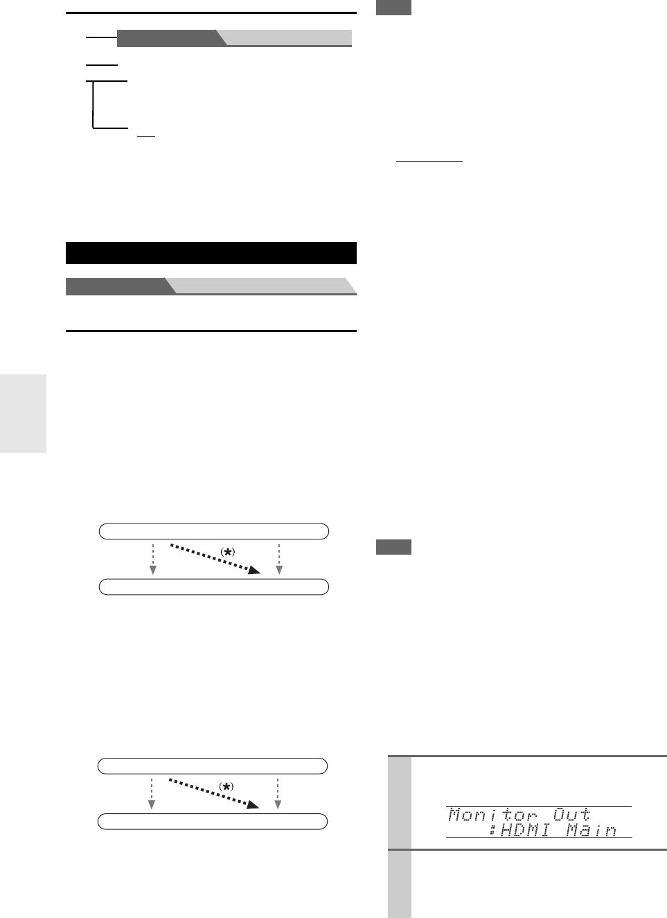
50
En
Explanatory Notes
Main Menu Input/Output Assign
Monitor Out
On the “Monitor Out” settings, you can select whether or
not to have the video sources’ images output through the
HDMI output, as well as whether to have the onscreen
setup menu output through the HDMI output or through
an analog output.
If you connect your TV to HDMI output, “Monitor Out”
setting is automatically set so that the onscreen setup
menus are displayed and composite video, S-Video, and
component video sources are upconverted* and output.
If you connect your TV to the COMPONENT VIDEO
MONITOR OUT (not the HDMI output), “Monitor Out”
setting is automatically set so that the onscreen setup
menus are displayed and composite video and S-Video
sources are upconverted* and output.
Note
• See “Video Connection Formats” (➔23) for charts showing
how the “Monitor Out” and “Resolution” settings (➔51)
affect the video signal flow through the AV controller.
■Monitor Out
`Analog:
Select this if your TV is connected to the COMPO-
NENT VIDEO MONITOR OUT, MONITOR OUT
S, or MONITOR OUT V.
`HDMI Main:
Select this if your TV is connected to the HDMI
OUT MAIN.
`HDMI Sub:
Select this if your TV is connected to the HDMI
OUT SUB.
`Both:
Select this if your TVs are connected to the HDMI
OUT MAIN and HDMI OUT SUB. Video signals
are output from both HDMI outputs at the resolution
supported by both TVs.
`Both(Main):
Select this if your TVs are connected to the HDMI
OUT MAIN and HDMI OUT SUB. Video signals
are output from both HDMI outputs but HDMI OUT
MAIN will become a priority; depending on the reso-
lution, video signals may not be output from HDMI
OUT SUB.
`Both(Sub):
Select this if your TVs are connected to the HDMI
OUT MAIN and HDMI OUT SUB. Video signals
are output from both HDMI outputs but HDMI OUT
SUB will become a priority; depending on the reso-
lution, video signals may not be output from HDMI
OUT MAIN.
Note
• If not connected to the same output you have selected in the
“Monitor Out” setting, the “Monitor Out” setting will be auto-
matically switched to “Analog” (➔24).
• When you select other than “Analog”, the onscreen setup menus
are output by only the HDMI output. If you’re not using the
HDMI output and select settings by mistake and the menus
disappear, press AV controller’s Monitor Out to select “Ana-
log”.
• For Deep Color output, if the “Monitor Out” setting is set to
“Both(Main)” or “Both(Sub)”, the number of bit may be lim-
ited due to the capability of your TV connected to a priority out-
put.
Changing “Monitor Out” setting manually
Input/Output Assign
a Menu selection
b Setting target
c Setting options (default setting underlined)
Main Menu Speaker Setup
■Subwoofer
`1ch:
Audio signal is outputted from SW1 jack
only.
`2ch:
Audio signal is outputted from SW1 and
SW2 jacks.
a
b
c
IN
OUT
Composite video, S-Video,
component video
Composite video, S-Video,
component video
HDMI
HDMI
IN
OUT
Composite video, S-Video
Composite video, S-Video
Component video
Component video
1Press Monitor Out on the front panel.
The current setting is displayed.
2Press Monitor Out on the front panel repeat-
edly to select:
`Analog, HDMI Main, HDMI Sub, Both,
Both(Main) or Both(Sub)
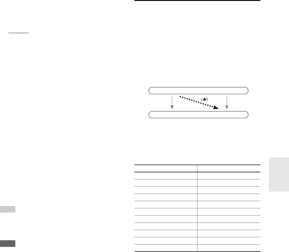
51
En
■Resolution
You can specify the output resolution for the HDMI output
and COMPONENT VIDEO MONITOR OUT and have
the AV controller upconvert the picture resolution as nec-
essary to match the resolution supported by your TV.
`Through*1:
Select this to pass video through the AV controller at
the same resolution and with no conversion.
`Auto*2:
Select this to have the AV controller automatically
convert video at resolutions not supported by your
TV.
`480p (480p/576p):
Select this for 480p or 576p output and video con-
version as necessary.
`720p:
Select this for 720p output and video conversion as
necessary.
`1080i:
Select this for 1080i output and video conversion as
necessary.
`1080p*2:
Select this for 1080p output and video conversion as
necessary.
`1080p/24*2:
Select this for 1080p output at 24 frames per second
and video conversion as necessary.
`Source:
Output will be according to the resolution level
which was set in the “Picture Adjust” setting
(➔62).
Tip
•The “Resolution” setting is set respectively of main, sub, and
analog.
• You can see the picture by pressing Enter to check the “Resolu-
tion” setting (excluding NET/USB input source).
Note
•If the “Monitor Out” setting is set to “Both”, this setting is fixed
at “Auto”.
• Depending on the incoming video signal, video playback may
not be smooth or the vertical resolution may be lowered. In this
case select other than “1080p/24”.
*1 PC IN (Analog RGB) input signal is output at 480p
(480p/576p), 720p, 1080i resolution when the “Monitor Out”
setting is set to “Analog” (➔50) and the “Resolution” set-
ting is set to “Through”.
*2 These settings are not available when the “Monitor Out” set-
ting is set to “Analog” (➔50).
HDMI Input
If you connect a video component to an HDMI input, you
must assign that input to an input selector. For example, if
you connect your Blu-ray Disc/DVD player to HDMI
IN 2, you must assign “HDMI 2” to the “BD/DVD” input
selector.
If you’ve connected your TV to the AV controller with an
HDMI cable, composite video, S-video and component
video sources can be upconverted* and output by the
HDMI output*1. You can set this for each input selector by
selecting the “-----” option.
*1 This applies only when “Monitor Out” setting is set to other
than “Analog” (➔50).
Here are the default assignments.
■BD/DVD, VCR/DVR, CBL/SAT, GAME, PC, TAPE,
TV/CD, PHONO, PORT
`HDMI 1, HDMI 2, HDMI 3, HDMI 4, HDMI 5,
HDMI 6, HDMI 7:
Select the HDMI IN to which the video component
has been connected.
`-----:
Output composite video, S-Video, and component
video sources from the HDMI output. The video out-
put signal from the HDMI output is the one config-
ured in “Component Video Input” (➔52).
•“AUX” is used only for input from the front panel.
• Each HDMI input cannot be assigned to two input selec-
tors or more. When HDMI 1 - HDMI 7 have already
been assigned, you must set first any unused input selec-
tors to “-----” or you will be unable to assign HDMI 1
- HDMI 7 to input selector.
Input selector Default assignment
BD/DVD HDMI 1
VCR/DVR HDMI 2
CBL/SAT HDMI 3
GAME HDMI 4
PC HDMI 5
AUX FRONT (Fixed)
TAPE -----
TUNER ----- (Fixed)
TV/CD -----
PHONO -----
PORT -----
IN
OUT
Composite video, S-Video,
component video
Composite video, S-Video,
component video
HDMI
HDMI
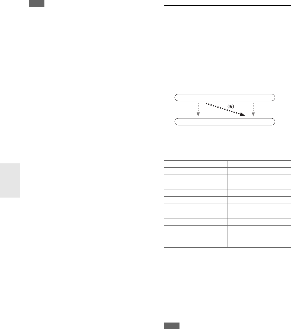
52
En
Note
• For composite video, S-Video, and component video upconver-
sion for the HDMI output, the “Monitor Out” setting must be
set to other than “Analog” (➔50), and the “HDMI Input” set-
ting must be set to “-----”. See “Video Connection Formats”
for more information on video signal flow and upconversion
(➔23).
• If no video component is connected to HDMI output (even if the
HDMI input is assigned), the AV controller selects the video
source based on the setting of “Component Video Input”.
• When an HDMI IN is assigned to an input selector as explained
here, the same HDMI IN will be set as a priority in the “Digital
Audio Input” (➔53). In this case, if you want to use the coaxial
or optical audio input, make the selection in the “Audio Selec-
tor” in the Home menu (➔70).
•“TUNER” selector cannot be assigned and is fixed at the
“-----” option.
• If you connect a component (such as UP-A1 Dock that seated
iPod) to UNIVERSAL PORT jack, you cannot assign any input
to “PORT” selector.
• Do not assign the component connected with the HDMI input to
“TV/CD” selector when you set “TV Control” setting to “On”
(➔67). Otherwise, appropriate CEC (Consumer Electronics
Control) operation will not be guaranteed.
Component Video Input
If you connect a video component to a component video
input, you must assign that input to an input selector. For
example, if you connect your Blu-ray Disc/DVD player to
COMPONENT VIDEO IN 2, you must assign “IN 2” to
the “BD/DVD” input selector.
If you’ve connected your TV to the AV controller with a
component video cable, you can set the AV controller so
that composite video and S-Video sources are upcon-
verted* and output by the COMPONENT VIDEO MONI-
TOR OUT*1. You can set this for each input selector by
selecting the “-----” option.
*1 This applies only when “Monitor Out” setting is set to “Ana-
log” (➔50).
Here are the default assignments.
■BD/DVD, VCR/DVR, CBL/SAT, GAME, PC, AUX,
TAPE, TV/CD, PHONO, PORT
`IN 1, IN 2, IN 3:
Select a corresponding component video input that
the video component has been connected.
`-----:
Select if you are using HDMI output, rather than the
COMPONENT VIDEO MONITOR OUT, for the
output from composite video, S-Video, and compo-
nent video sources.
Note
• For composite video and S-Video upconversion for the COM-
PONENT VIDEO MONITOR OUT, the “Monitor Out” set-
ting must be set to “Analog” (➔50), and the “Component
Video Input” setting must be set to “-----”. See “Video Con-
nection Formats” for more information on video signal flow and
upconversion (➔23).
• If not connected to the same output you have selected in the
“Monitor Out” setting, the “Monitor Out” setting will be auto-
matically switched to “Analog” (➔50).
•“TUNER” selector cannot be assigned and is fixed at the
“-----” option.
• If you connect a component (such as UP-A1 Dock that seated
iPod) to the UNIVERSAL PORT jack, you cannot assign any
input to “PORT” selector.
Input selector Default assignment
BD/DVD IN 1
VCR/DVR - ----
CBL/SAT IN 2
GAME IN 3
PC -----
AUX -----
TAPE -----
TUNER ----- (Fixed)
TV/CD -----
PHONO -----
PORT -----
IN
OUT
Composite video, S-Video
Composite video, S-Video
Component video
Component video
53
En
Digital Audio Input
If you connect a component to a digital audio input, you
must assign that input to an input selector. For example, if
you connect your CD player to the OPTICAL IN 1, you
must assign “OPT 1” to the “TV/CD” input selector.
Here are the default assignments.
■BD/DVD, VCR/DVR, CBL/SAT, GAME, PC, TAPE,
TV/CD, PHONO, PORT
`COAX 1, COAX 2, COAX 3, OPT 1, OPT 2,
OPT 3:
Select a corresponding digital audio input that the
component has been connected.
`-----:
Select if the component is connected to an analog
audio input.
•“AUX” is used only for input from the front panel.
Note
•When an HDMI IN is assigned to an input selector in “HDMI
Input” (➔51), the same HDMI IN will be set as a priority in this
assignment. In this case, if you want to use the coaxial or optical
audio input, make the selection in the “Audio Selector” in the
Home menu (➔70).
• Available sampling rate for PCM signals from a digital input
(optical and coaxial) is 32/44.1/48/88.2/96 kHz/16, 20, 24 bit.
•“TUNER” selector cannot be assigned and is fixed at the
“-----” option.
• If you connect a component (such as UP-A1 Dock that seated
iPod) to the UNIVERSAL PORT jack, you cannot assign any
input to “PORT” selector.
Analog Audio Input
If you connect a component to the AV controller’s analog
multichannel input, you must assign that input to an input
selector. For example, if you connect your Blu-ray
Disc/DVD player to the MULTI CH input, you must assign
it to the “BD/DVD” input selector.
If you connect a component to the AV controller’s bal-
anced input, you must assign that input to an input selec-
tor. For example, if you connect your CD player to the
balanced input, you must assign it to the “TV/CD” input
selector.
■Multich
`BD/DVD, VCR/DVR, CBL/SAT, GAME, PC, AUX,
TAPE, TV/CD, PHONO:
You can assign the multichannel input to the input
selectors.
`-----:
If you don’t want to assign the multichannel input,
set to “-----”.
Note
• To listen to the component connected to the multichannel input,
make the selection in the “Audio Selector” in the Home menu
(➔70).
Subwoofer Input Sensitivity
`0dB to 15dB in 5 dB step.
Some DVD players output the LFE channel from their
analog subwoofer output at 15 dB higher than normal.
With this setting, you can change the AV controller’s
subwoofer sensitivity to match your DVD player.
Note
• This setting only affects signals connected to the AV controller’s
multichannel input SUBWOOFER jack.
• If you find that your subwoofer is too loud, try the 10 dB or
15 dB setting.
• This setting cannot be selected when “-----” is selected in the
“Multich” setting.
■Balance
`BD/DVD, VCR/DVR, CBL/SAT, GAME, PC, AUX,
TAPE, TV/CD, PHONO:
You can assign the balanced input to the input selec-
tors.
`-----:
If you don’t want to assign the balanced input, set to
“-----”.
Input Channel
`Mono(L):
Select if the source is mono and you’ve connected it
to the BALANCE L INPUT jack.
`Stereo:
Select if the source is stereo and you’ve connected it
to the BALANCE L/R INPUT jacks.
Input selector Default assignment
BD/DVD COAX 1
VCR/DVR COAX 2
CBL/SAT COAX 3
GAME OPT 1
PC -----
AUX FRONT (Fixed)
TAPE -----
TUNER ----- (Fixed)
TV/CD OPT 2
PHONO -----
PORT -----
54
En
Main menu Speaker Setup
Here you can check the settings made by
Audyssey MultEQ XT32 Room Correction and Speaker
Setup, or set them manually, which is useful if you change
one of the connected speakers after using
Audyssey MultEQ XT32 Room Correction and Speaker
Setup.
Note
• These settings are disabled when:
– a pair of headphones is connected, or
–the “Audio TV Out” setting is set to “On” (➔66) and an
input selector other than HDMI is selected.
Speaker Settings
To use bi-amping, you must change the
“Speakers Type(Front)” setting. For details on speaker
wire connection, see “Bi-amping the Front Speakers”
(➔16).
Note
• When bi-amping is used, the AV controller is able to drive up to
7.2 speakers in the main room.
• Before you change these settings, turn down the volume.
■Speakers Type(Front)
`Normal:
Select this if you’ve connected your front speakers
normally.
`Bi-Amp:
Select this if you’ve connected your front speakers
for bi-amped operation. The Bi AMP indicator will
light (➔9).
Note
• Surround back speakers cannot be used if you select “Bi-Amp”.
•If the “Front High + Front Wide” setting is set to “Yes ”, the
“Speakers Type(Front)” setting is fixed at “Normal”.
■Front High + Front Wide
`Yes:
Front High + Front Wide on.
`No:
Front High + Front Wide off.
Listening mode that make use of “Front High + Front
Wide” setting is as follows;
Audyssey DSX (PLII/Neo:6 + Audyssey DSX included),
Orchestra, Unplugged, Studio-Mix, TV Logic,
Game-RPG, Game-Action, Game-Rock, Game-Sports,
All Ch Stereo, Full Mono.
Note
• When you have selected “Ye s ”,
–the “Surround Back” setting is set to “None”.
–the “Front High” or “Front Wide” setting is set to
“80Hz(THX)” if set to “None”.
• When you have selected “No”, the “Front Wide” setting is set
to “None” if “Front High” and “Front Wide” settings are set to
anything other than “None”.
•The “Front High + Front Wide” setting cannot be used if
“Speakers Type(Front)” is set to “Bi-Amp”.
Speaker Configuration
With these settings, you can specify which speakers are
connected and a crossover frequency for each speaker.
Specify “Full Band” for speakers that can output low fre-
quency bass sounds adequately, for example, speakers
with a good sized woofer. For smaller speakers, specify a
crossover frequency. Sounds below the crossover fre-
quency will be output by the subwoofer instead of the
speaker. Refer to your speaker’s manuals to determine the
optimum crossover frequencies.
If you set up your speakers using Audyssey MultEQ XT32
Room Correction and Speaker Setup, please make sure
manually that any THX speakers are set to “80Hz(THX)”
crossover.
■Subwoofer
`1ch:
Audio signal is outputted from SW1 jack only.
`2ch:
Audio signal is outputted from SW1 and SW2
jacks.
`No:
Select if no subwoofer is connected.
■Front
`Full Band
`40Hz, 45Hz, 50Hz, 55Hz, 60Hz, 70Hz, 80Hz(THX),
90Hz, 100Hz, 110Hz, 120Hz, 130Hz, 150Hz, 200Hz
Note
•If the “Subwoofer” setting is set to “No”, the “Front” setting is
fixed at “Full Band”.
■Center*1, Surround*1, Surround Back*2*3*4*5
`Full Band
`40Hz, 45Hz, 50Hz, 55Hz, 60Hz, 70Hz, 80Hz(THX),
90Hz, 100Hz, 110Hz, 120Hz, 130Hz, 150Hz, 200Hz
`None:
Select if no speaker is connected.
■Front Wide*1*2*6, Front High*1*2*6
`Full Band
`40Hz, 45Hz, 50Hz, 55Hz, 60Hz, 70Hz, 80Hz(THX),
90Hz, 100Hz, 110Hz, 120Hz, 130Hz, 150Hz, 200Hz
`None:
Select if no speaker is connected.
Speaker Setup
Some of the settings in this section are set automatically
by Audyssey MultEQ®XT32 Room Correction and
Speaker Setup (➔29).
If you change these settings, you must run
Audyssey MultEQ XT32 Room Correction and
Speaker Setup again (➔29).
This setting is set automatically by
Audyssey MultEQ XT32 Room Correction and Speaker
Setup function (➔29).

55
En
Note
*1 “Full Band” can be selected only when “Full Band” is
selected in the “Front” setting.
*2 If the “Surround” setting is set to “None”, this setting cannot
be selected.
*3 If the “Surround” setting is set to anything other than “Full
Band”, “Full Band” cannot be selected here.
*4 If the “Bi-Amp” is being used (➔54), this setting cannot be
selected.
*5 This setting cannot be used if the “Front High + Front
Wide” setting is set to “Ye s ” (➔54).
*6 This setting is set to “None” if the “Front High + Front
Wide” setting is set to “No” (➔54).
■Surround Back Ch
`1ch:
Select if only one surround back speaker is con-
nected.
`2ch:
Select if two (left and right) surround back speakers
are connected.
Note
•If the “Surround Back” setting is set to “None”, this setting
cannot be selected.
■LPF of LFE
(Low-Pass Filter for the LFE Channel)
`80Hz, 90Hz, 100Hz, 110Hz, 120Hz
With this setting, you can specify the cutoff frequency
of the LFE channel’s low-pass filter (LPF), which can
be used to filter out unwanted hum. The LPF only
applies to sources that use the LFE channel.
■Double Bass
With the Double Bass function, you can boost bass out-
put by feeding bass sounds from the front left, right, and
center channels to the subwoofer.
`On:
Double Bass function on.
`Off(THX):
Double Bass function off.
Note
• This function can be set only if the “Subwoofer” setting is set to
“1ch” or “2ch”, and the “Front” setting is set to “Full Band”.
• If you’re using THX-certified speakers, select “Off(THX)”.
Speaker Distance
Here you can specify the distance from each speaker to the
listening position so that the sound from each speaker
arrives at the listener’s ears as the sound designer
intended.
■Unit
`feet:
Distances can be set in feet. Range: “0.2ft” to
“30.0ft” in 0.2 foot steps.
`meters:
Distances can be set in meters. Range: “0.06m” to
“9.00m” in 0.06 meter steps.
(The default setting varies from country to country.)
■Left, Front Wide Left, Front High Left, Center,
Front High Right, Front Wide Right, Right,
Surround Right, Surround Back Right,
Surround Back Left, Surround Left,
Subwoofer 1, Subwoofer 2*1
`Specify the distance from the each speaker to your lis-
tening position.
Note
• Speakers that you set to “No” or “None” in the
“Speaker Configuration” cannot be selected (➔54).
*1 If the “Subwoofer” setting is set to “1ch”, this setting cannot
be selected (➔54).
Level Calibration
Here you can adjust the level of each speaker with the
built-in test tone so that the volume of each speaker is the
same at the listening position.
■Left, Front Wide Left, Front High Left, Center*1,
Front High Right, Front Wide Right, Right,
Surround Right, Surround Back Right,
Surround Back Left, Surround Left
`–12.0dB to 0.0dB to +12.0dB in 0.5 dB step.
■Subwoofer 1*1, Subwoofer 2*1*2
`–15.0dB to 0.0dB to +12.0dB in 0.5 dB step.
Note
• Speakers that you set to “No” or “None” in the
“Speaker Configuration” cannot be selected (➔54).
• The speakers cannot be calibrated while the AV controller is
muted.
• The test tone is output at the standard level for THX, which is
0 dB (absolute volume setting 82). If you normally listen at vol-
ume settings below this, be careful because the test tone will be
much louder.
•The “Level Calibration” setting cannot be selected if “Audio
TV Out” setting is set to “On”.
*1 For the center speaker and subwoofer, the level settings made
by using the Home menu are saved (➔27).
*2 If the “Subwoofer” setting is set to “1ch”, this setting cannot
be selected (➔54).
Tip
• If you’re using a handheld sound level meter, adjust the level of
each speaker so that it reads 75 dB SPL at the listening position,
measured with C-weighting and slow reading.
This setting is NOT set automatically by
Audyssey MultEQ®XT32 Room Correction and
Speaker Setup function (➔29).
This setting is set automatically by
Audyssey MultEQ XT32 Room Correction and Speaker
Setup function (➔29).
This setting is set automatically by
Audyssey MultEQ XT32 Room Correction and Speaker
Setup function (➔29).
56
En
Equalizer Settings
With the Equalizer settings, you can adjust the tone of
speakers individually with a 15-band equalizer. The vol-
ume of each speaker can be set (➔55).
■Equalizer
`Manual:
You can adjust the equalizer for each speaker manu-
ally. If you selected “Manual”, continue with this
procedure.
`Audyssey:
This is selected automatically by
Audyssey MultEQ XT32 Room Correction and
Speaker Setup function. The Audyssey indicator will
light (➔9) and “Dynamic EQ” (➔59) and
“Dynamic Volume” (➔60) become available.
When “Audyssey” is selected, “Dolby Volume”
becomes “Off” automatically (➔58).
`Off:
Tone off, response flat.
THX Audio Setup
With the “Surr Back Speaker Spacing” setting, you can
specify the distance between your surround back speakers.
If you’re using a THX-certified subwoofer, set the “THX
Ultra2/Select2 Subwoofer” setting to “Yes”. You can
then apply THX’s Boundary Gain Compensation (BGC)
to compensate the perceived exaggeration of low frequen-
cies for listeners sitting very close to a room boundary
(i.e., wall).
You can also set the THX Loudness Plus. When the
“Loudness Plus” is set to “On”, it is possible to enjoy
even subtle nuances of audio expression at low volume.
This result is only available when the THX listening mode
is selected.
■Surr Back Speaker Spacing
`<1ft(<0.3m):
Select this if your surround back speakers are
between 0 and 1 foot (0–30 cm) apart.
`1ft - 4ft (0.3m - 1.2m):
Select this if your surround back speakers are
between 1 and 4 feet (0.3–1.2 m) apart.
`> 4ft (> 1.2m):
Select this if your surround back speakers are more
than 4 feet (1.2 m) apart.
Note
• Cannot be set if “Surround Back Ch” is set to “1ch” (➔55) or
“Surround Back” is set to “None” (➔54).
■THX Ultra2/Select2 Subwoofer
`No:
Select this if you do not have a THX-certified sub-
woofer.
`Ye s :
Select this if you have a THX-certified subwoofer.
Note
•If the “Subwoofer” setting is set to “No”, this setting cannot be
selected (➔54).
■BGC
`Off:
Select this to turn off BGC.
`On:
Select this to turn on BGC.
Note
• This setting is only available if “THX Ultra2/Select2 Sub-
woofer” is set to “Ye s ”.
■Loudness Plus
`Off:
Select this to turn off Loudness Plus.
`On:
Select this to turn on Loudness Plus.
This setting is set automatically by
Audyssey MultEQ®XT32 Room Correction and
Speaker Setup function (➔29).
1Press w to select “Channel”, and then use
e/r to select a speaker.
2Use q/w to select a frequency, and then use
the e/r to adjust the level at that frequency.
The volume at each frequency can be adjusted
from –6dB to 0dB to +6dB in 1 dB steps.
Note
• You can select: “25Hz”, “40Hz”, “63Hz”,
“100Hz”, “160Hz”, “250Hz”, “400Hz”, “630Hz”,
“1000Hz”, “1600Hz”, “2500Hz”, “4000Hz”,
“6300Hz”, “10000Hz”, or “16000Hz”. And for the
subwoofer, “25Hz”, “40Hz”, “63Hz”, “100Hz”, or
“160Hz”.
• While the Direct listening mode is selected, the
equalizer settings have no effect.
Tip
• Low frequencies (e.g., 63Hz) affect bass sounds;
high frequencies (e.g., 16000Hz) affect treble
sounds.
3Use q to select “Channel”, and then use e/r
to select another speaker.
Repeat steps 1 and 2 for each speaker.
You cannot select speakers that you set to “No”
or “None” in the “Speaker Configuration”
(➔54).
57
En
■Preserve THX Settings
`Ye s :
Audyssey Dynamic EQ® /
Audyssey Dynamic Volume® / Dolby Volume will
not be active in THX listening mode.
`No:
Audyssey Dynamic EQ /
Audyssey Dynamic Volume / Dolby Volume will be
active in THX listening mode depending on the set-
ting.
Note
• This setting is fixed at “Yes ” if “Loudness Plus” is set to “On”.
Main menu Audio Adjust
With the Audio Adjust functions and settings, you can
adjust the sound and listening modes as you like.
Multiplex/Mono
■Multiplex
This setting determines which channel of a stereo multi-
plex source is output. Use it to select audio channels or
languages with multiplex sources, multilingual TV
broadcasts, and so on.
Input Channel
`Main:
The main channel is output.
`Sub:
The sub channel is output.
`Main/Sub:
Both the main and sub channels are output.
■Mono
This setting specifies the channel to be used for playing
any 2-channel digital source such as Dolby Digital, or
2-channel analog/PCM source in the Mono listening
mode.
Input Channel
`Left + Right:
Both the left and right channels are output.
`Left:
Only the left channel is output.
`Right:
Only the right channel is output.
Output Speaker
`Center:
Mono audio is output by the center speaker.
`Left / Right:
Mono audio is output by the front left and right
speakers.
This setting determines which speakers output mono
audio when the Mono listening mode is selected.
Note
• If the “Center” setting is set to “None” (➔54), this setting is
fixed at “Left / Right”.
Dolby
■PLIIx Music (2ch Input)
These settings apply to only 2-channel stereo sources.
If you’re not using any surround back speakers, these
settings apply to Dolby Pro Logic II, not Dolby Pro
Logic IIx.
Panorama
`On:
Panorama function on.
`Off:
Panorama function off.
With this setting, you can broaden the width of the front
stereo image when using the Dolby Pro Logic IIx Music
listening mode.
Dimension
`–3 to 0 to +3
With this setting, you can move the sound field forward
or backward when using the Dolby Pro Logic IIx Music
listening mode. Higher settings move the sound field
backward. Lower settings move it forward.
If the stereo image feels too wide, or there’s too much
surround sound, move the sound field forward to
improve the balance. Conversely, if the stereo image
feels like it’s in mono, or there’s not enough surround
sound, move it backward.
Center Width
`0 to 3 to 7
With this setting, you can adjust the width of the sound
from the center speaker when using the Dolby Pro
Logic IIx Music listening mode. Normally, if you’re
using a center speaker, the center channel sound is out-
put by only the center speaker. (If you’re not using a
center speaker, the center channel sound will be distrib-
uted to the front left and right speakers to create a phan-
tom center). This setting controls the front left, right,
and center mix, allowing you to adjust the weight of the
center channel sound.
THX Loudness Plus
THX Loudness Plus is a new volume control technology
featured in THX Ultra2 Plus™ and THX Select2 Plus™
Certified receivers. With THX Loudness Plus, home
theater audiences can now experience the rich details in
a surround mix at any volume level. A consequence of
turning the volume below Reference Level is that cer-
tain sound elements can be lost or perceived differently
by the listener. THX Loudness Plus compensates for the
tonal and spatial shifts that occur when the volume is
reduced by intelligently adjusting ambient surround
channel levels and frequency response. This enables
users experience the true impact of soundtracks regard-
less of the volume setting. THX Loudness Plus is auto-
matically applied when listening in any THX listening
mode. The new THX Cinema, THX Music, and THX
Games modes are tailored to apply the proper THX
Loudness Plus settings for each type of content.
Audio Adjust

58
En
■PLIIz Height Gain
The Height Gain Control in Dolby Pro Logic IIz
enables the listener to select how much gain is applied
to the front high speakers. There are three settings,
“Low”, “Mid” and “High”, and the front high speakers
are accentuated in that order. While “Mid” is the default
listening setting, the listener may adjust the Height Gain
Control to their personal preference.
`Low:
Low PLIIz Height Gain becomes active.
`Mid:
Medium PLIIz Height Gain becomes active.
`High:
High PLIIz Height Gain becomes active.
Note
•If the “Front High” settings is set to “None” (➔54), this setting
cannot be selected.
■Dolby EX
This setting determines how Dolby EX encoded signals
are handled. This setting is unavailable if no surround
back speakers are connected. This setting is effective
with Dolby Digital, Dolby Digital Plus and Dolby
TrueHD only.
`Auto:
If the source signal contains a Dolby EX flag, the
Dolby EX or THX Surround EX listening mode is
used.
`Manual:
You can select any available listening mode.
Note
•If the “Surround Back” setting is set to “None” (➔54), this
setting cannot be selected.
•If the “Front High” or “Front Wide” setting is enabled (➔54),
this setting is fixed at “Manual”.
■Dolby Volume
`Off:
Dolby Volume off.
`On:
Dolby Volume on.
The - (Dolby) Vol indicator will light (➔9).
Dolby Volume automatically adjusts the difference in vol-
ume levels which can occur between different content or
source components, freeing the user from having to make
volume adjustments. Also, by adjusting the frequency bal-
ance according to the playback volume, it recreates the
original source audio. Dolby Volume therefore provides
comfortable listening, effectively controlling the volume
level difference without unnatural changes in volume or
sound quality to recreate the balance and nuance of the
source audio.
Note
• When the “Dolby Volume” setting is set to effective,
Audyssey Dynamic EQ® and Audyssey Dynamic Volume® will
be set to “Off” and “Equalizer” setting will be set to “Off” from
“Audyssey” or remain set to “Manual”.
• If you would like to use Dolby Volume in THX listening modes,
set “Loudness Plus” setting to “Off” and set “Preserve THX
Settings” setting to “No”.
• When the “Dolby Volume” is set to “On”, the Late Night func-
tion cannot be set.
■Volume Leveler
`Off:
Volume Leveler off.
`Low:
Low Compression Mode becomes active.
`Mid:
Medium Compression Mode becomes active.
`High:
High Compression Mode becomes active. This set-
ting affects volume the most, causing all sounds to
be of equal loudness.
“Volume Leve le r” maintains the perceived loudness of all
content for example, from different channels or input
sources.
Note
•If the “Dolby Volume” setting is set to “Off”, this setting cannot
be selected.
■Half Mode
`Off:
Half Mode off.
`On:
Half Mode on.
The Half Mode parameter turns Dolby Volume Half Mode
processing ON and OFF.
In OFF mode, Dolby Volume applies a bass and treble
attenuation to the audio when the system gain exceeds ref-
erence level. This enables a more perceptually flat listen-
ing experience as human ears are more sensitive to bass
and treble at higher levels. Some listeners however, prefer
to have more bass and treble performance at higher gain
levels.
Note
•If the “Dolby Volume” setting is set to “Off”, this setting cannot
be selected.
• During Half Mode ON playback, Dolby Volume does not apply
a bass and treble attenuation when the system volume exceeds
reference level thereby boosting perception of high and low fre-
quencies.
DTS
■Neo:6 Music
Center Image
`0 to 2 to 5
The DTS Neo:6 Music listening mode creates 6-channel
surround sound from 2-channel stereo sources. With
this setting, you can specify by how much the front left
and right channel output is attenuated in order to create
the center channel.
Setting a value “0” in the middle is set to hear a sound.
Sound is spread in left and right (the outside) so that the
set value is made big. Please adjust by liking.
59
En
Audyssey DSX™
■Soundstage
`–3dB to Reference to +3dB
With this setting, you can adjust the soundstage when using
Audyssey DSX™.
Note
•If the “Center” setting is set to “None”, or both “Front High”
and “Front Wide” settings are set to “None” (➔54), this setting
cannot be selected.
Theater-Dimensional
■Listening Angle
`Wide:
Select if the listening angle is greater than 30
degrees.
`Narrow:
Select if the listening angle is less than 30 degrees.
With this setting, you can optimize the Theater-Dimen-
sional listening mode by specifying the angle of the
front left and right speakers relative to the listening
position. Ideally, the front left and right speakers should
be equidistant from the listening position and at an
angle close to one of the two available settings.
LFE Level
■Dolby Digital*1, DTS*2, Multich PCM, Dolby
TrueHD, DTS-HD Master Audio, DSD*3
`–QdB, –20dB, –10dB, or 0dB
With these settings, you can set the level of the LFE (Low
Frequency Effects) channel individually for each input
sources.
If you find that low-frequency effects are too loud when
using one of these sources, change the setting to “–20dB”
or “–QdB”.
*1 Dolby Digital and Dolby Digital Plus sources.
*2 DTS and DTS-HD High Resolution Audio sources.
*3 DSD (Super Audio CD) sources.
Direct
■Analog
Subwoofer
`Off:
Analog audio signals (bass signals) are not output.
`On:
Analog audio signals (bass signals) are output.
This setting determines whether or not analog audio sig-
nals (bass signals) are output from front speakers when the
Direct listening mode is selected.
Note
• If the “Subwoofer” setting is set to “No” (➔54), this setting
cannot be selected.
■DSD
DAC Direct
`Off:
DSD signals are processed by the DSP.
`On:
DSD signals are not processed by the DSP.
This setting determines whether or not DSD (Super Audio
CD) audio signals are passed through the DSP for A/V
Sync, delay, etc., processing when the Direct listening
mode is selected.
Note
• Once you have selected “On”, only DAC Direct will be available
for selection.
Items can be set individually for each input selector.
Main menu Source Setup
Audyssey
When Audyssey MultEQ®XT32 Room Correction and
Speaker Setup is complete, the “Equalizer” (➔56) will
be set to “Audyssey” and the “Dynamic EQ” will be set
to “On”.
■Dynamic EQ
`Off:
Audyssey Dynamic EQ® off.
`On:
Audyssey Dynamic EQ on.
The Dynamic EQ indicator will light (➔9).
With Audyssey Dynamic EQ, you can enjoy great
sound even when listening at low volume levels.
Audyssey Dynamic EQ solves the problem of deterio-
rating sound quality as volume is decreased by taking
into account human perception and room acoustics. It
does so by selecting the correct frequency response and
surround volume levels moment-by-moment so that the
content sounds the way it was created at any volume
level — not just at reference level.
Front left speaker Front right speaker
Listening angle: 30°
Source Setup
Preparation
Press the input selector buttons to select an input source.
60
En
■Reference Level
Audyssey Dynamic EQ® Reference Level Offset
`0dB:
It should be used when listening to movies.
`5dB:
Select this setting for content that has a very wide
dynamic range, such as classical music.
`10dB:
Select this setting for jazz or other music that has a
wider dynamic range. This setting should also be
selected for TV content as that is usually mixed at
10 dB below film reference.
`15dB:
Select this setting for pop/rock music or other pro-
gram material that is mixed at very high listening
levels and has a compressed dynamic range.
Movies are mixed in rooms calibrated for film refer-
ence. To achieve the same reference level in a home the-
ater system each speaker level must be adjusted so that
–30 dBFS band-limited (500 Hz to 2000 Hz) pink noise
produces 75 dB sound pressure level at the listening
position. A home theater system automatically cali-
brated by Audyssey MultEQ®XT32 will play at refer-
ence level when the master volume control is set to the
0 dB position. At that level you can hear the mix as the
mixers heard it.
Audyssey Dynamic EQ is referenced to the standard
film mix level. It makes adjustments to maintain the ref-
erence response and surround envelopment when the
volume is turned down from 0 dB. However, film refer-
ence level is not always used in music or other non-film
content. Audyssey Dynamic EQ Reference Level Offset
provides three offsets from the film level reference
(5 dB, 10 dB, and 15 dB) that can be selected when the
mix level of the content is not within the standard.
Note
•If “Dynamic EQ” setting is set to “Off”, this setting cannot be
selected.
■Dynamic Volume
`Off:
Audyssey Dynamic Volume® off.
`Light:
Light Compression Mode becomes active.
`Medium:
Medium Compression Mode becomes active.
`Heavy:
Heavy Compression Mode becomes active. This set-
ting affects volume the most, causing all sounds to
be of equal loudness.
Note
• Even if you have selected other than “Audyssey” in “Equalizer”
setting after performing Audyssey MultEQ XT32 Room Correc-
tion and Speaker Setup, selecting “On” in the “Dynamic EQ”
will change the “Equalizer” setting to “Audyssey” (➔56).
• If you would like to use Audyssey Dynamic Volume, when
using THX listening modes, set “Loudness Plus” setting to
“Off” (➔56) and set “Preserve THX Settings” setting to “No”
(➔57).
•When “Dynamic Volume” is set to effective, “Equalizer” is set
to “Audyssey” (➔56) and “Dynamic EQ” is set to “On”.
When “Dynamic EQ” is set to “Off”, “Dynamic Volume”
becomes “Off” automatically.
•When “Dynamic Volume” is set to effective, the Dynamic Vol
indicator will light (➔9).
• If Direct listening mode is selected, these settings cannot be
selected.
•“Dynamic EQ” and “Dynamic Volume” settings cannot be
used while a pair of headphones is connected.
•When “Dynamic EQ” or “Dynamic Volume” is set to effective,
“Dolby Volume” will be set to “Off” (➔58).
Audyssey MultEQ XT32 then removes the distortion
caused by room acoustics by capturing room acoustical
problems over the listening area in both the frequency and
time domain. The result is clear, well-balanced sound for
everyone. Enabling Audyssey MultEQ XT32 allows you
to also use Audyssey Dynamic EQ, which maintains the
proper octave-to-octave balance at any volume level.
Before using this function, connect and position all of
your speakers.
About Audyssey Dynamic EQ
Audyssey Dynamic EQ solves the problem of deterio-
rating sound quality as volume is decreased by taking
into account human perception and room acoustics.
Dynamic EQ selects the correct frequency response and
surround levels moment-by-moment at any
user-selected volume setting. The result is bass
response, tonal balance, and surround impression that
remain constant despite changes in volume. Dynamic
EQ combines information from incoming source levels
with actual output sound levels in the room, a prerequi-
site for delivering a loudness correction solution.
Audyssey Dynamic EQ works in tandem with
Audyssey MultEQ XT32 to provide well-balanced
sound for every listener at any volume level.
About Audyssey Dynamic Volume
Audyssey Dynamic Volume solves the problem of large
variations in volume level between television programs,
commercials, and between the soft and loud passages of
movies. Dynamic Volume looks at the preferred volume
setting by the user and then monitors how the volume of
program material is being perceived by listeners in real
time to decide whether an adjustment is needed. When-
ever necessary, Dynamic Volume makes the necessary
rapid or gradual adjustments to maintain the desired
playback volume level while optimizing the dynamic
range. Audyssey Dynamic EQ is integrated into
Dynamic Volume so that as the playback volume is
adjusted automatically, the perceived bass response,
tonal balance, surround impression, and dialog clarity
remain the same whether watching movies, flipping
between television channels, or changing from stereo to
surround sound content.
61
En
IntelliVolume
■IntelliVolume
`–12dB to 0dB to +12dB in 1 dB steps.
With IntelliVolume, you can set the input level for each
input selector individually. This is useful if one of your
source components is louder or quieter than the others.
Use e/r to set the level.
If a component is noticeably louder than the others, use e
to reduce its input level. If it’s noticeably quieter, use r to
increase its input level.
A/V Sync
■A/V Sync
`0msec to 250msec in 2 msec steps.
When using your DVD player’s progressive scanning
function, you may find that the picture and sound are out
of sync. With the A/V Sync setting, you can correct this
by applying a delay to the audio signal.
To view the TV picture while setting the delay, press
Enter.
To return to the previous screen, press Return.
If HDMI Lip Sync is enabled (➔66) and your TV or dis-
play supports HDMI Lip Sync, the displayed delay time
will be the summation of the A/V Sync delay time and the
HDMI Lip Sync delay time. The HDMI Lip Sync delay
time is displayed underneath in parentheses.
Note
•“A/V Sync” is disabled when the Direct listening mode is used
with an analog input source.
•“A/V Sync” is not operable when the input selector is set to
“NET/USB”.
Name Edit
You can enter a custom name for each individual input
selector (excluding Tuner) and radio preset for easy iden-
tification. When entered, the custom name will appear on
the display.
The custom name is edited using the character input
screen.
■Name
To correct a character:
Note
• To name a radio preset, use Tuner to select AM or FM, and then
select the preset (➔33).
•(North American models) You cannot enter a custom name for
SIRIUS radio presets.
•“Name Edit” is not operable when the input selector is set to
“NET/USB”.
To restore a custom name to the default, erase the custom
name by entering an empty white space for each letter.
1Use q/w/e/r to select a character, and then
press Enter.
Repeat this step to enter up to 10 characters.
2When you’ve finished, to store a name, be sure
to use q/w/e/r to select “OK”, and then press
Enter. Otherwise it will not be saved.
1Use q/w/e/r to select “ ”(Left) or
“ ”(Right), and then press Enter.
2Press Enter several times to select the incorrect
character (The cursor moves one letter each
time Enter is pressed).
3Use q/w/e/r to select the correct character,
and then press Enter.
BD/DVD
Shift All Erase
Shift All Erase
4-4. Name Edit
Name
D/DVD
abcde f gh i j k lm
nopq r s t uvwxy z
1234567890
–`
Space Back Space
Shift OK
{}|: <>
?
ABCDEFGH I JKLM
NOPQRSTUVWXYZ
;
’,
./
[]
Space Back Space
Shift OK
!
@
#$%
^& ()_ ~
+10 CLR
+10 CLR
Name input area
Shift*1:
Switches the displayed character.
Space:
Enters a space character.
(Left)/ (Right):
Selected when the cursor is moved within the Name
input area.
Back Space*2:
“Back Space” moves the cursor backward one char-
acter space. In addition, “Back Space” deletes the
character to the left of the cursor.
OK:
Selects when the entry is complete.
Tip
*1 You can also be performed on the remote controller by
using +10.
*2 Press CLR on the remote controller, you can delete all
characters in the input.
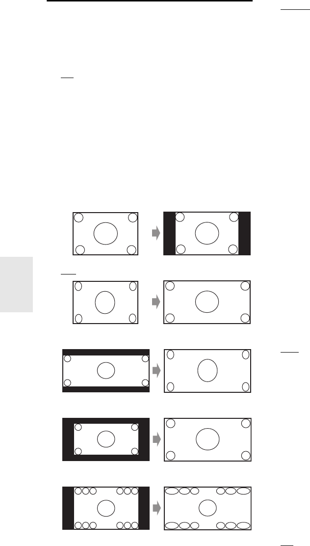
62
En
Picture Adjust
Using “Picture Adjust”, you can adjust the picture qual-
ity and reduce any noise appearing on the screen.
To view the TV picture while setting, press Enter. To
return to the previous screen, press Return.
■Game Mode
`Off:
Game Mode off.
`On:
Game Mode on.
If video signal delay occurs during playback on a video
component (i.e. game console), select the corresponding
input source and set the “Game Mode” setting to “On”.
The delay will decrease but in return the picture quality
will become poor.
■Wide Mode*1*5
This setting determines the aspect ratio.
`4:3:
`Full:
`Zoom:
`Wide Zoom:
`Smart Zoom:
■Picture Mode*1
`Custom:
All settings can be performed manually.
`ISF Day:
Setting when a room is bright.
`ISF Night:
Setting when a room is dark.
`Cinema:
Selected when the picture source is movie film, etc.
`Game:
Selected when the picture source is game console.
`Through:
Default values are adapted for all settings.
With “Picture Mode”, you can change the following set-
tings to be suitable for the movie or game screen by one
operation; “Film Mode”, “Edge Enhancement”, “Mos-
quito NR”, “Random NR”, “Block NR”, “Resolution”,
“Brightness”, “Contrast”, “Hue”, “Saturation”,
“Gamma”, “Red Brightness”, “Red Contrast”, “Green
Brightness”, “Green Contrast”, “Blue Brightness”,
“Blue Contrast”.
The receiver has been designed to incorporate setup and
calibration standards established by the Imaging Science
Foundation (ISF). The ISF has developed carefully
crafted, industry-recognized standards for optimal video
performance and has implemented a training program for
technicians and installers to use these standards to obtain
optimal picture quality from the receiver. Accordingly,
Onkyo recommends that setup and calibration be per-
formed by an ISF Certified installation technician.
■Film Mode*2*4*6
`Auto:
Adjusts to the picture source, automatically selecting
“Film Mode”.
`Video:
Selected when the picture source is video, etc.
`Film:
Selected when the picture source is movie film, etc.
DVD-Video disc content originates from either film
(recorded at 24 frames per second) or video intended for
TV (recorded at 30 frames per second). With the default
“Film Mode” setting of “Auto”, the AV controller auto-
matically detects the type of content and processes it
accordingly to achieve the best picture quality. If the AV
controller detects the type of content incorrectly due to
characteristics of the disc, you can select “Video” or
“Film” manually.
■Edge Enhancement*2*4*7
`Off:
Edge enhancement off.
`Low:
Low edge enhancement.
`Mid:
Medium edge enhancement.
`High:
High edge enhancement.
With Edge Enhancement, you can make the picture appear
sharper.

63
En
■Mosquito NR*2*3*4*6
`Off:
Mosquito noise reduction off.
`Low:
Low mosquito noise reduction.
`Mid:
Medium mosquito noise reduction.
`High:
High mosquito noise reduction.
With Mosquito Noise Reduction, you can remove the
shimmering or haziness that sometimes appears around
objects in the picture. Mosquito noise can be an issue with
overly compressed MPEG content.
■Random NR*2*3*4*6
`Off:
Random noise reduction off.
`Low:
Low random noise reduction.
`Mid:
Medium random noise reduction.
`High:
High random noise reduction.
With Random Noise Reduction, you can remove indis-
criminate picture noise, such as film grain.
■Block NR*2*3*4*6
`Off:
Block noise reduction off.
`On:
Block noise reduction on.
With Block Noise Reduction, you can remove the block
distortion that sometimes appears in the picture. Block
noise can be an issue with overly compressed MPEG con-
tent.
■Resolution*2*4
`Through:
Select this to pass video through the AV controller at
the same resolution and with no conversion.
`Auto:
Select this to have the AV controller automatically
convert video at resolutions not supported by your
TV. When the “Monitor Out” is set to “Analog”,
this setting will be changed to “Through”.
`480p (480p/576p):
Select this for 480p or 576p output and video con-
version as necessary.
`720p:
Select this for 720p output and video conversion as
necessary.
`1080i:
Select this for 1080i output and video conversion as
necessary.
`1080p:
Select this for 1080p output and video conversion as
necessary. When the “Monitor Out” is set to “Ana-
log”, this setting will be changed to “1080i”.
`1080p/24:
Select this for 1080p output at 24 frames per second
and video conversion as necessary. When the “Mon-
itor Out” is set to “Analog”, this setting will be
changed to “1080i”.
You can specify the output resolution for the HDMI out-
puts and have the AV controller upconvert the picture res-
olution as necessary to match the resolution supported by
your TV.
Available only when “Source” has been selected in the
“Resolution” of the “Monitor Out” setting (➔51).
■Brightness*1*2*4
`–50 to 0 to +50
With this setting you can adjust the picture bright-
ness. “–50” is the darkest. “+50” is the brightest.
■Contrast*1*2*4
`–50 to 0 to +50
With this setting you can adjust contrast. “–50” is the
least. “+50” is the greatest.
■Hue*1*2*4
`–20 to 0 to +20
With this setting you can adjust the red/green bal-
ance. “–20” is the strongest green. “+20” is the
strongest red.
■Saturation*1*2*4
`–50 to 0 to +50
With this setting you can adjust saturation. “–50” is
the weakest color. “+50” is the strongest color.
■Gamma*2*4
`–3 to 0 to +3
Adjust the balance of incoming picture R (red), G
(green), and B (blue) color data signal to the output
color data signal.
■Red Brightness*2*4
`–50 to 0 to +50
With this setting you can adjust the picture red
brightness. “–50” is the darkest. “+50” is the bright-
est.
■Red Contrast*2*4
`–50 to 0 to +50
With this setting you can adjust red contrast. “–50” is
the least. “+50” is the greatest.
■Green Brightness*2*4
`–50 to 0 to +50
With this setting you can adjust the picture green
brightness. “–50” is the darkest. “+50” is the bright-
est.
■Green Contrast*2*4
`–50 to 0 to +50
With this setting you can adjust green contrast.
“–50” is the least. “+50” is the greatest.
■Blue Brightness*2*4
`–50 to 0 to +50
With this setting you can adjust the picture blue
brightness. “–50” is the darkest. “+50” is the bright-
est.

64
En
■Blue Contrast*2*4
`–50 to 0 to +50
With this setting you can adjust blue contrast. “–50”
is the least. “+50” is the greatest.
Tip
*1 This procedure can also be performed on the remote controller
by using the Home menu (➔27).
*2 Press CLR if you want to reset to the default value.
Note
• If you are using the analog RGB input, the following settings
have no effect: “Film Mode”, “Edge Enhancement”, “Mos-
quito NR”, “Random NR” and “Block NR”.
•“Picture Adjust” is not operable when the input selector is set
to “NET/USB”.
*3 These settings have no effect in the case of HD input source
(720p,1080i,1080p,1080p/24).
*4 When the “Picture Mode” setting is set to anything other than
“Custom”, this setting cannot be used.
*5 Depending on the input and output resolutions, “Smart
Zoom” may not be used.
*6 When the “Game Mode” setting is set to “On”, this setting
cannot be selected.
*7 This setting has no effect in the case of downconversion.
You can assign a default listening mode to each input
source that will be selected automatically when you select
each input source. For example, you can set the default lis-
tening mode to be used with Dolby Digital input signals.
You can select other listening modes during playback, but
the mode specified here will be resumed once the AV con-
troller has been set to Standby.
Main menu Listening Mode Preset
■Analog/PCM
With this setting, you can specify the listening mode to
be used when an analog (CD, TV, LD, VHS, MD, turn-
table, radio, cassette, cable, satellite, etc.) or PCM digi-
tal (CD, DVD, etc.) audio signal is played.
■Mono/Multiplex Source
With this setting, you can specify the listening mode to
be used when a mono digital audio signal is played
(DVD, etc.).
■2ch Source
With this setting, the default listening mode for 2-chan-
nel (2/0) stereo sources in a digital format, such as
Dolby Digital or DTS.
■Dolby D/Dolby D Plus/TrueHD
With this setting, you can specify the listening mode to
be used when a Dolby Digital or Dolby Digital Plus for-
mat digital audio signal is played (DVD, etc.). Specifies
the default listening mode for Dolby TrueHD sources,
such as Blu-ray or HD DVD (input via HDMI).
■DTS/DTS-ES/DTS-HD
With this setting, you can specify the listening mode to
be used when a DTS or DTS-HD High Resolution
Audio format digital audio signal is played (DVD, LD,
CD, etc.). Specifies the default listening mode for
DTS-HD Master Audio sources, such as Blu-ray or HD
DVD (input via HDMI).
■Other Multich Source
Specifies the default listening mode for multichannel
PCM sources from HDMI IN such as DVD-Audio, and
DSD multichannel sources such as Super Audio CD.
Main menu Miscellaneous
Volume Setup
■Volume Display
`Absolute:
Display range is “Min”, “0.5” through “99.5”,
“Max”.
`Relative(THX):
Display range is “–QdB”, “–81.5dB” through
“+18.0dB”.
With this setting, you can choose how the volume level is
displayed.
The absolute value 82 is equivalent to the relative value
0dB.
■Muting Level
`–QdB (fully muted), –50dB to –10dB in 10 dB steps.
This setting determines how much the output is muted
when the muting function is used (➔27).
Listening Mode Preset
1Use q/w to select the input source that you want to
set, and then press Enter.
The following menu appears.
For “TUNER” input selector only “Analog” will be
available. For “NET/USB” input source only “Digi-
tal” will be available.
Note
• If you connect an input component (such as UP-A1 series
Dock that seated iPod) to the UNIVERSAL PORT jack,
you can assign only listening modes for the analog sound
to “PORT” selector.
2Use q/w to select the signal format that you want
to set, and then use e/r to select a listening mode.
Only listening modes that can be used with each
input signal format can be selected (➔43 to 48).
The “Last Valid” option means that the listening
mode selected last will be used.
The “Straight Decode” option means that straight
decoding listening mode (Dolby Digital, DTS, etc.)
is selected.
1. BD/DVD
2. VCR/DVR
3. CBL/SAT
4. GAME
5. PC
6. AUX
5. Listening Mode Preset
Miscellaneous
65
En
■Maximum Volume
`Off, 50 to 99 (Absolute display)
`Off, –32dB to +17dB (Relative display)
With this setting, you can limit the maximum volume.
To disable this setting, select “Off”.
■Power On Volume
`Last, Min, 1 to 99 or Max (Absolute display)
`Last, –QdB, –81dB to +18dB (Relative display)
With this preference, you can specify the volume set-
ting to be used each time the AV controller is turned
on.
To use the same volume level that was used when the AV
controller was turned off, select “Last”.
The “Power On Volume” cannot be set higher than the
“Maximum Volume” setting.
■Headphone Level
`–12dB to 0dB to +12dB
With this preference, you can specify the headphone vol-
ume relative to the main volume. This is useful if there’s a
volume difference between your speakers and your head-
phones.
OSD Setup
■On Screen Display
This preference determines whether operation details
are displayed on-screen when an AV controller function
is adjusted.
`On:
Displayed.
`Off:
Not displayed.
Even when “On” is selected, operation details may not be
output if the input source is connected to an HDMI IN.
■TV Format (Australian models)
For the on-screen setup menus to display properly, you
must specify the TV system used in your area.
`Auto:
Select this to automatically detect the TV system
from the video input signals.
`NTSC:
Select this if the TV system in your area is NTSC.
`PAL:
Select this if the TV system in your area is PAL.
■Language
`English, Deutsch, Français, Español, Italiano,
Nederlands, Svenska, 中文
This setting determines the language used for the
on-screen setup menus.
12V Trigger A/B/C Setup
See “Using the 12V Triggers” (➔85).
Main menu Hardware Setup
Remote ID
■Remote ID
`1, 2, or 3
When several Integra/Onkyo components are used in
the same room, their remote ID codes may overlap. To
differentiate the AV controller from the other compo-
nents, you can change its remote ID from “1”, to “2” or
“3”.
Note
• If you do change the AV controller’s remote ID, be sure to
change the remote controller to the same ID (see below), other-
wise, you won’t be able to control it with the remote controller.
Changing the Remote Controller’s ID
Multi Zone
See “Setting the Multi Zone” (➔82).
Tuner
For FM/AM tuning to work properly, you must specify the
FM/AM frequency step used in your area. Note that when
this setting is changed, all radio presets will be deleted.
■FM/AM Frequency Step (North American
models)
`200kHz/10kHz:
Select if 200 kHz/10 kHz steps are used in your area.
`50kHz/9kHz:
Select if 50 kHz/9 kHz steps are used in your area.
■AM Frequency Step (Australian models)
`10kHz:
Select if 10 kHz steps are used in your area.
`9kHz:
Select if 9 kHz steps are used in your area.
SIRIUS Settings (North American models)
See “Listening to SIRIUS Satellite Radio®” (➔33) for
more information.
Hardware Setup
1While holding down Receiver, press and hold
down Setup until Receiver lights (about 3 sec-
onds).
2Use the number buttons to enter ID 1, 2, or 3.
Receiver flashes twice.

66
En
HDMI
■Audio TV Out
`Off:
The audio is not output from the HDMI output.
`On:
The audio is output from the HDMI output.
This preference determines whether the incoming audio
signal is output from the HDMI output. You may want to
turn this preference on if your TV is connected to the
HDMI output and you want to listen to the audio from a
connected component through your TV’s speakers. Nor-
mally, this should be set to “Off”.
Note
• Listening mode cannot be changed when this setting is set to
“On” and the input source is not HDMI.
•If
“On” is selected and the audio can be output from the TV, the
AV controller will output no sound through its speakers. In this
case, “TV Sp On” appears on the display.
• When “TV Control” is set to “On”, this setting is fixed to
“Auto”.
• With some TVs and input signals, no sound may be output even
when this setting is set to “On” (➔67).
• When the “Audio TV Out” setting is set to “On”, or “TV Con-
trol” is set to “On” (➔67) and you’re listening through your
TV’s speakers (➔19), if you turn up the AV controller’s volume
control, the sound will be output by the AV controller’s front left
and right speakers. To stop the AV controller’s speakers produc-
ing sound, change the settings, change your TV’s settings, or
turn down the AV controller’s volume.
•If the “Monitor Out” setting is set to “Both(Main)” or
“Both(Sub)” (➔50) and if your TV connected to a priority out-
put cannot output the audio, the sound will be heard from AV
controller’s speakers.
■Lip Sync
`Disable:
HDMI lip sync disabled.
`Enable:
HDMI lip sync enabled.
The AV controller can be set to automatically correct any
delay between the video and the audio, based on the data
from the connected monitor.
Note
• This function works only if your HDMI-compatible TV supports
HDMI Lip Sync.
• You can check the amount of delay being applied by the HDMI
Lip Sync function on the A/V Sync screen.
•If the “Monitor Out” setting is set to “HDMI Main”,
“Both(Main)” or “Both” (➔50), the delay will be corrected in
accordance with the monitor connected to HDMI OUT MAIN.
On the other hand, if “HDMI Sub” or “Both(Sub)” is selected,
the delay will be corrected in accordance with the monitor con-
nected to HDMI OUT SUB.
■HDMI Control(RIHD)
`Off:
p disabled.
`On:
p enabled.
This function allows p-compatible components
connected via HDMI to be controlled with the AV control-
ler (➔107 to 108).
Note
• When set to “On” and close the menu, the name of connected
p-compatible components and “RIHD On” are dis-
played on the AV controller.
“Search…” → “(name)” → “RIHD On”
When the AV controller cannot receive the name of the compo-
nent, it is displayed as “Player*” or “Recorder*”, etc (“*”
means the number of two or more component).
•When an p-compatible component is connected to the
AV controller via the HDMI cable, the name of the connected
component is displayed on the AV controller display. For exam-
ple, while you are watching TV broadcasting, if you operate a
Blu-ray Disc/DVD player (being powered on) by the remote
control of the AV controller, the name of the Blu-ray Disc/DVD
player is displayed on the AV controller.
•Set to “Off” when a connected piece of equipment is not com-
patible or it is unclear whether the equipment is compatible or
not.
• If movement is unnatural when set to “On”, change the setting
to “Off”.
• Refer to the connected component’s instruction manual for
details.
•The p control does not support HDMI OUT SUB. Use
HDMI OUT MAIN instead.
• When the source equipment is connected with the u connec-
tion, it may malfunction if “HDMI Control(RIHD)” is set to
“On”.
■Audio Return Channel
`Off:
Select “Off” if you don’t want to use audio return
channel (ARC) function.
`Auto:
The audio signal from your TV tuner can be sent to
the HDMI OUT MAIN of the AV controller.
Audio return channel (ARC) function enables an HDMI
(Audio Return Channel) capable TV to send the audio
stream to the HDMI OUT MAIN of the AV controller. To
use this function, you must select the TV/CD input selec-
tor and your TV must support ARC function.
Note
•The “Audio Return Channel” setting can be set only when the
“HDMI Control(RIHD)” setting is set to “On”.
• This setting is set to “Auto” automatically when the “HDMI
Control(RIHD)” is set to “On” first time.

67
En
■Power Control
`Off:
Power Control disabled.
`On:
Power Control enabled.
To link the power functions of p-compatible com-
ponents connected via HDMI, select “On”.
This setting is set to “On” automatically when the
“HDMI Control(RIHD)” is set to “On” first time.
Note
•The
“Power Control” setting can be set only when the “HDMI
Control(RIHD)” setting is set to “On”.
• HDMI power control only works with p-compatible
components that support it and may not work properly with
some components due to their settings or compatibility.
• When set to “On”, power consumption will increase.
• When set to “On”, regardless of whether the AV controller is On
or in Standby, both audio and video stream from an HDMI input
will be output to the TV or other components via HDMI connec-
tion (HDMI pass through function).
• The power consumption during standby mode will increase dur-
ing the HDMI pass through function; however if your TV sup-
ports CEC (Consumer Electronics Control), the power
consumption can be saved in the following cases:
– The TV is in standby mode.
– You are watching a TV program.
• Refer to the connected component’s instruction manual for
details.
■TV Control
`Off:
TV Control disabled.
`On:
TV Control enabled.
Set to “On” when you want to control the AV controller
from an p-compatible TV that is connected to
HDMI.
Note
• Do not assign the component connected with the HDMI input to
the TV/CD selector when you set “TV Control” setting to “On”.
Otherwise, appropriate CEC (Consumer Electronics Control)
operation is not guaranteed.
•Set to “Off” when the TV is not compatible or when it is unclear
whether the TV is compatible or not.
•The
“TV Control” setting can be set only when the “HDMI
Control(RIHD)” (➔66) and “Power Control” (➔67) set-
tings are both set to “On”.
• Refer to the connected component’s instruction manual for
details.
Auto Power Down
■Auto Power Down
`Off:
Auto Power Down disabled.
`On:
Auto Power Down enabled.
When “Auto Power Down” is set to “On”, AV controller
will automatically perform STANDBY operation if there
is no operation for 30 minutes with no audio and no video
signal input.
“Auto Power Down” will display on the display and OSD
from 30 seconds before the Auto Power Down functions.
Default setting: On (Australian models), Off (North
American models)
Note
• Depending on some sources, the auto power-down function may
activate during playback.
• The Auto Power Down function does not work when Zone 2 or
Zone 3 is on.
Network
See “Network Settings” (➔77).
Firmware Update
See “Firmware Update” for update procedure (➔109).
Note
• Perform the firmware update only when an announcement is
posted on the Integra web site. See the Integra web site for latest
information.
• It takes about 60 minutes to complete the firmware update.
• When updating a firmware from a USB mass storage device, the
AV controller searches the device which is connected earlier dur-
ing power on. If two devices have been connected at the time of
power on, the AV controller will search the device on the front
panel.
■Version
The current version of the firmware is displayed.
■Receiver
`via NET:
You can update the firmware via Internet. Check the
network connection before update.
`via USB:
You can update the firmware from a USB mass stor-
age device.
You can update the AV controller’s firmware. Do not shut-
down the power of the AV controller while update.
■Universal Port
`via NET:
You can update the firmware via Internet. Check the
network connection before update.
`via USB:
You can update the firmware from a USB mass stor-
age device.
You can update the Onkyo dock’s firmware. Do not shut-
down the power of the AV controller while update.
Note
• This update shall not be performed when no dock is connected
to UNIVERSAL PORT jack.
After changing the settings of the “HDMI Con-
trol(RIHD)”, “Audio Return Channel”, “Power Con-
trol”, or “TV Control”, turn off the power to all
connected pieces of equipment and then turn them on
again. Refer to the user’s manuals for all connected
pieces of equipment.

68
En
With this preference, you can protect your settings by
locking the setup menus.
Main menu Lock Setup
■Setup
`Locked:
Setup menus locked.
`Unlocked:
Setup menus not locked.
When the setup menus are locked, you cannot change any
setting.
You can change various audio settings from the Home
menu (➔27).
Note
• These settings are disabled when the “Audio TV Out” setting is
set to “On” (➔66) and an input selector other than HDMI is
selected.
Tone Control Settings
You can adjust the bass for the front, front wide, front
high, center, surround, surround back and subwoofer
speakers and treble for the front, front wide, front high,
center, surround and surround back speakers, except when
the Direct or THX listening mode is selected.
■Bass
`–10dB to 0dB to +10dB in 2 dB steps.
You can boost or cut low-frequency sounds output.
■Treble
`–10dB to 0dB to +10dB in 2 dB steps.
You can boost or cut high-frequency sounds output.
Operating on the AV controller
Note
• This setting is not available when the multichannel analog input
is selected.
• To bypass the bass and treble tone circuits, select the Direct or
THX listening mode.
Speaker Levels
You can adjust the volume of each speaker while listening
to an input source.
These temporary adjustments are cancelled when the AV
controller is set to Standby. To save the setting you made
here, go to “Level Calibration” (➔55) before setting the
AV controller to Standby.
■Subwoofer 1
`–15.0dB to 0.0dB to +12.0dB in 0.5 dB steps.
■Subwoofer 2
`–15.0dB to 0.0dB to +12.0dB in 0.5 dB steps.
■Center
`–12.0dB to 0.0dB to +12.0dB in 0.5 dB steps.
Note
• You cannot use this function while the AV controller is muted.
• Speakers that are set to “No” or “None” in the
“Speaker Configuration” (➔54) cannot be adjusted.
• This function will not work when the Direct listening mode is
selected to play analog audio.
• This setting cannot be used while a pair of headphones is con-
nected.
Audyssey Settings
■Dynamic EQ
See “Dynamic EQ” of “Source Setup” (➔59).
■Dynamic Volume
See “Dynamic Volume” of “Source Setup” (➔60).
Dolby Volume
■Dolby Volume
See “Dolby Volume” of “Audio Adjust” (➔58).
Lock Setup
Using the Audio Settings
1Press Receiver followed by Home.
2Use q/w to select “Audio”, and then use q/w/e/r
to make the desired selection.
1Press Tone repeatedly to select either “Bass” or
“Treble”.
2Use –/+ to adjust.

69
En
Late Night
With the Late Night function, you can reduce the dynamic
range of Dolby Digital material so that you can still hear
quiet parts even when listening at low volume lev-
els—ideal for watching movies late at night when you
don’t want to disturb anyone.
■Late Night
For Dolby Digital and Dolby Digital Plus sources, the
options are:
`Off:
Late Night function off.
`Low:
Small reduction in dynamic range.
`High:
Large reduction in dynamic range.
For Dolby TrueHD sources, the options are:
`Auto:
The Late Night function is set to “On” or “Off”
automatically.
`Off:
Late Night function off.
`On:
Late Night function on.
Note
• The effect of the Late Night function depends on the material
that you are playing and the intention of the original sound
designer, and with some material there will be little or no effect
when you select the different options.
• The Late Night function can be used only when the input source
is Dolby Digital, Dolby Digital Plus, or Dolby TrueHD.
• The Late Night function is set to “Off” when the AV controller
is set to Standby. For Dolby TrueHD sources, it will be set to
“Auto”.
Music Optimizer
The Music Optimizer function enhances the sound quality
of compressed music files. Use it with music files that use
“lossy” compression, such as MP3.
■Music Optimizer
`Off:
Music Optimizer off.
`On:
Music Optimizer on. The M.Opt indicator will light
(➔9).
Note
• The Music Optimizer function only works with PCM digital
audio input signals with a sampling rate below 48 kHz and ana-
log audio input signals. The Music Optimizer is disabled when
the Direct listening mode is selected.
• The setting is stored individually for each input selector.
Screen Centered Dialog
“Screen Ctr Dialog” is a function for moving the Center
image of dialog etc. upwards through use of the front high
speaker to fix the image to the display height.
■Screen Ctr Dialog
As the value increases, the Center image moves upwards.
`0:
Screen Centered Dialog off.
`1 to 5:
Screen Centered Dialog on.
Note
•The “Screen Ctr Dialog” can be used when supported listening
mode is selected and “Center” and “Front High” are set to
effective in “Speaker Configuration” (➔54).
• This setting cannot be used while a pair of headphones is con-
nected.
Re-EQ
With the Re-EQ function, you can compensate a
soundtrack whose high-frequency content is too harsh,
making it more suitable for home theater viewing.
■Re-EQ
`Off:
Re-EQ Function off.
`On:
Re-EQ Function on.
This function can be used with the following listening
modes: Dolby Digital, Dolby Digital Plus,
Dolby TrueHD, Multichannel, DTS, DTS-HD High Reso-
lution Audio, DTS-HD Master Audio, DTS Express,
DSD, Dolby EX, Dolby Pro Logic IIz Height, Dolby
PLIIx Movie, Neo:6 Cinema and 5.1-channel source +
Neo:6, and Neural Surround.
■Re-EQ(THX)
`Off:
Re-EQ (THX) Function off.
`On:
Re-EQ (THX) Function on.
This function can be used with the following listening
modes: THX Cinema, THX Surround EX, and
THX Ultra2 Cinema.
Note
• Settings for the Re-EQ function are kept in each listening mode.
However, in THX listening mode, when the AV controller is
turned off, it will return to “On”.
• This setting cannot be used while a pair of headphones is con-
nected.

70
En
Audio Selector
You can set priorities of audio output when there are both
digital and analog inputs.
■Audio Selector
`ARC:
The audio signal from your TV tuner can be sent to
the HDMI OUT MAIN of the AV controller.*1
With this selection the TV’s audio can be automati-
cally selected as a priority among other assignments.
`HDMI:
This can be selected when HDMI IN has been
assigned as an input source. If both HDMI (HDMI
IN) and digital audio inputs (COAXIAL IN or OPTI-
CAL IN) have been assigned, HDMI input is auto-
matically selected as a priority.
`COAX:
This can be selected when COAXIAL IN has been
assigned as an input source. If both coaxial and
HDMI inputs have been assigned, coaxial input is
automatically selected as a priority.
`OPT:
This can be selected when OPTICAL IN has been
assigned as an input source. If both optical and
HDMI inputs have been assigned, optical input is
automatically selected as a priority.
`Multich:
The AV controller always outputs analog signals
from multichannel analog input.
`Balance:
The AV controller always outputs analog signals
from balanced input.
`Analog:
The AV controller always outputs analog signals.
Note
• The setting is stored individually for each input selector.
• This setting can be made only for the input source that is
assigned as HDMI IN, COAXIAL IN, or OPTICAL IN.
• To select the digital audio input, see “Digital Audio Input” for
more detail (➔53).
•To select “Multich”, you must assign the multichannel input
(➔53).
•To select “Balance”, you must assign the balanced input (➔53).
*1 You can select “ARC” if you select the TV/CD input selector.
But you cannot select it if you’ve selected “Off” in the “Audio
Return Channel” setting (➔66).
Setting the Incoming Digital Signal (Fixed
Mode)
By pressing Enter while selecting “HDMI”, “COAX”,
“OPT” in the “Audio Selector”, you can specify the input
signal in the Fixed Mode. Pressing Enter again allows
you to return to the “Audio Selector” setting.
Normally, the AV controller detects the signal format
automatically. However, if you experience either of the
following issues when playing PCM or DTS material, you
can manually set the signal format to PCM or DTS.
• If the beginnings of tracks from a PCM source are cut
off, try setting the format to PCM.
• If noise is produced when fast forwarding or reversing a
DTS CD, try setting the format to DTS.
■Fixed Mode
`Auto:
The format is detected automatically. If no digital
input signal is present, the corresponding analog
input is used instead.
`PCM:
Only 2-channel PCM format input signals will be
heard. If the input signal is not PCM, the PCM indi-
cator will flash and noise may also be produced.
`DTS:
Only DTS (but not DTS-HD) format input signals
will be heard. If the input signal is not DTS, the DTS
indicator will flash and there will be no sound.
Note
• The setting is stored individually for each input selector.
• The setting will be reset to “Auto” when you change the setting
in the “Audio Selector”.
71
En
NET/USB
The AV controller is network-ready, which means you can
hook it up to your home network with a standard Ethernet
cable and enjoy the music files stored on your computer or
media server. If your network is connected to the Internet,
you can also enjoy Internet radio.
Network Requirements
■Ethernet Network
For best results, a 100Base-TX switched Ethernet network
is recommended. Although it’s possible to play music on a
computer that’s connected to the network wirelessly, play-
back may be unreliable, so wired connections are recom-
mended.
■Ethernet Router
A router manages the network, routing data and supplying
IP addresses. Your router must support the following:
• NAT (Network Address Translation). NAT allows sev-
eral networked computers to access the Internet simulta-
neously via a single Internet connection. The AV
controller needs Internet access for Internet radio.
• DHCP (Dynamic Host Configuration Protocol). DHCP
supplies IP addresses to network devices, allowing them
to configure themselves automatically.
• A router with a 100Base-TX switch built-in is recom-
mended.
Some routers have a modem built-in, and some ISPs
require you to use specific routers. Please consult your ISP
or computer dealer if you’re unsure.
■CAT5 Ethernet cable
Use a shielded CAT5 Ethernet cable (straight-type) to con-
nect the AV controller to your home network.
■Internet Access (for Internet radio)
To receive Internet radio, your Ethernet network must
have Internet access. A narrowband Internet connection
(e.g., 56K modem, ISDN) will not provide satisfactory
results, so a broadband connection is strongly recom-
mended (e.g., cable modem, xDSL modem, etc). Please
consult your ISP or computer dealer if you’re unsure.
Note
• To receive Internet radio with the AV controller, your broadband
Internet connection must be working and able to access the Web.
Consult your ISP if you have any problems with your Internet
connection.
• The AV controller uses DHCP to configure its network settings
automatically. If you want to configure these settings manually,
see “Network Settings” (➔77).
• The AV controller does not support PPPoE settings, so if you
have a PPPoE-type Internet connection, you must use a
PPPoE-compatible router.
• Depending on your ISP, you may need to specify a proxy server
to use Internet radio. If your computer is configured to use a
proxy server, use the same settings for the AV controller (➔77).
To connect the AV controller to your home network, plug
one end of a shielded CAT5 Ethernet cable into the AV
controller’s ETHERNET port, and plug the other end into
a LAN port on your router or switch.
The following diagram shows how you can connect the
AV controller to your home network. In this example, it’s
connected to a LAN port on a router, which has a 4-port
100Base-TX switch built-in.
About NET Connecting the AV Controller
Internet radio
Modem
Router
Computer or media server
LAN/Ethernet port
WAN port
LAN port
LAN port
72
En
To receive Internet radio, you must connect the AV con-
troller to a network with Internet access (➔71).
You can select Internet radio stations by connecting to the
AV controller from your computer and selecting stations
in your Web browser. Preset up to 40 Internet radio sta-
tions.
Internet radio URLs in the following formats are sup-
ported: PLS, M3U, and podcast (RSS). However, depend-
ing on the type of data or audio format used by the Internet
radio station, you may not be able to listen to some sta-
tions.
Note
• If you’re using a narrowband Internet connection (e.g., 56K
modem or ISDN), depending on the station, Internet radio may
not work satisfactorily. For best results, use a broadband connec-
tion (e.g., cable modem, xDSL modem, etc).
Listening to vTuner Internet Radio
This unit includes the full vTuner Internet Radio Service
at no additional charge. Once you have connected your
unit to the Internet you can select vTuner Internet Radio to
search for and play Internet radio stations and podcasts at
any time. To enhance your Internet radio experience, the
http://onkyo.vtuner.com/ portal is available to you as an
easy way to browse to find stations, set up/organize your
favorites, add your own stations, get help, etc. After the
first time you try Internet radio/vTuner on your unit you
can use the MAC Address of your unit to create a member
login account (email address and password) on the
http://onkyo.vtuner.com/ portal. To verify your MAC
Address, please see “Network Settings” (➔77).
Listening to Other Internet Radio
To listen to other internet radio stations, insert the follow-
ing step after step 1 in the “Listening to vTuner Internet
Radio”.
Listening to Internet Radio
1Press NET/USB repeatedly to select the Internet
Radio screen.
The NETWORK indicator lights (➔9).
NET/USB
Menu
q/w/e/r
Enter
Display
Top Menu
Internet Radio
1. vTuner Internet Radio
2. Pandora Internet Radio
3. Rhapsody
4. SIRIUS Internet Radio
5. Slacker Personal Radio
6. Mediafly
7. Napster
8. ---
9. ---
10. ---
*1
Go to Menu
MENU
Note
• When the NETWORK indicator flashes, confirm that the
Ethernet cable is firmly connected to the AV controller.
• Services available may vary depending on the region. See
the separate instructions for more information.
*1 MENU:
When menu operations are enabled, “MENU” appears.
Press Menu to display the menu.
2Use q/w to select “vTuner Internet Radio”, and
then press Enter.
3Use q/w to select a program, and then press
Enter.
Playback starts and the following screen appears.
*2 Press Menu to allow selection from the following menu
items.
`Stations like this:
Stations like the one currently being played
back are displayed.
`Add this station to preset:
Add a station to the list.
Press Top Menu to go to the top menu of the
Internet Radio services.
Tip
• If you press Display, you can toggle between the play-
back screen and the list screen.
1On your computer, start your Web browser and
enter the AV controller’s IP address in the
browser’s Internet address (URL) field.
The browser connects to the AV controller (WEB
Setup Menu).
Note
• The AV controller’s IP address is shown on the “Net-
work” screen (➔77).
• If you’re using DHCP, your router may not always allocate
the same IP address to the AV controller, so if you find that
you can’t connect to the AV controller, recheck the AV
controller’s IP address on the “Network” screen.
2Click on the “Preset Internet Radio” tab.
0:00:00
WMA 128kbps 16bit/44.1kHz
1. fm indie 104
The internet’s best source for i
- - -
All Stations
Go to Menu
*2
73
En
Registering Presets*1
Once you’ve added a station to the list, simply select it on
the Internet Radio screen, and then press Enter to start
playback.
*1 From the search results you can preset the stations and songs
but cannot listen to them directly.
■Items on the Internet Radio Top Menu
`Create new preset:
Add a favorite station or Internet Radio to the pre-
sets.
`Rename this preset:
You can rename the preset.
`Delete this preset:
This will delete the preset.
■Station and Song Presets
You can add the currently playing song or station to the
presets.
1. Press Menu with the station selected or while a song
is playing.
2. Use q/w to select “Add this station to preset”, and
press Enter.
This section explains how to play music files on a com-
puter or media server through the AV controller. See
“Supported Audio File Formats” to “About DLNA” for
details on supported music servers and music file formats.
For Windows Media Player 11, see “Windows Media
Player 11 Setup” (➔74).
3Enter the preset name and Internet address
(URL).
4Click “Save” to save the Internet radio station.
Playing Music Files on a Server
Unit Information
WEB Setup Menu
Preset Internet Radio
SaveCustomer Setting Refresh
1Internet Radio Information 2
Network setting
Delete
Delete
Delete
No
1
2
3
Name
Tuner Internet Radio
URL
1Start your computer or media server.
2Press NET/USB to select the “Server” screen.
The NETWORK indicator lights (➔9).
Note
•When the NETWORK indicator flashes, confirm the net-
work connection.
• To update the screen, press Return.
3Use q/w to select a server, and then press Enter.
A list of items on the server appears.
Search
You can search for music by Artist, Album, or Track.
Note
• The search function does not work with media servers
which do not support this function.
• Depending on the sharing settings in the media server, the
AV controller may not able to access the content. Refer to
the instruction manual of the media server.
NET/USB
Display
Enter
q/w/e/r
Return
1, 3, 2, 5,
4, 7, 6
Random
Repeat
1 / 10
Server
Server1
Server2
Server3
Server4
Server5
Server6
Server7
Server8
Server9
Server10
1 / 8
Search
Recently Added
Artists
Album
Songs
Genre
Year
Rating
Server1
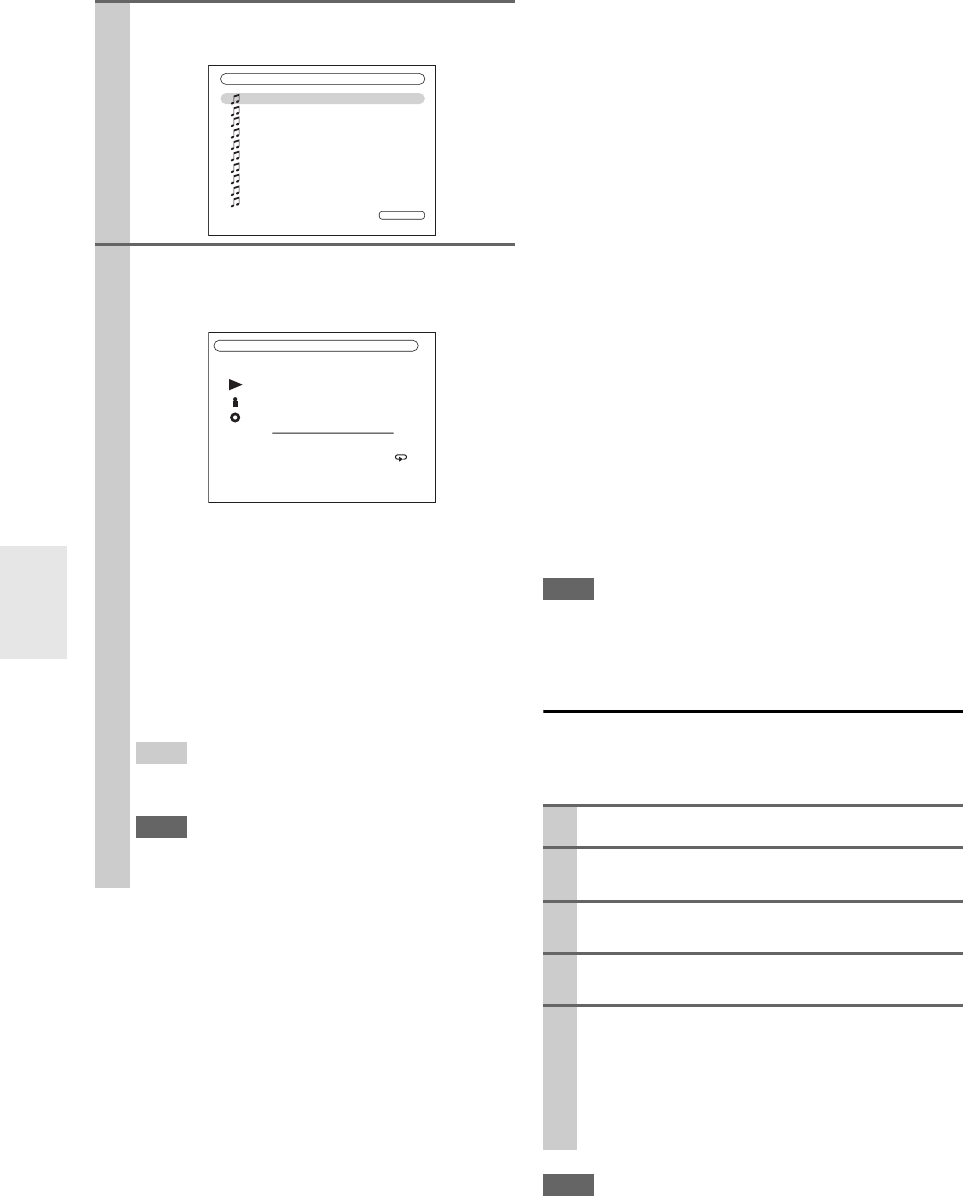
74
En
Random Playback
The Random function can only be set while the PLAY
screen is displayed.
To play songs in random order, during playback (or while
playback is paused or stopped), press Random. All of the
songs in the current folder will be played in random order.
When all of the songs in the folder have been played once,
they’ll all be played again in a different random order. To
cancel random playback, press Random again.
Random playback supports up to 20000 songs per folder.
If a folder contains more than this, songs over 20000 are
not included in random playback.
Repeat Playback
The Repeat function can only be set while the PLAY
screen is displayed.
To play songs repeatedly, during playback (or while play-
back is paused or stopped), press Repeat repeatedly to
select: Repeat1, Repeat Folder, Repeat All, or Off.
In Repeat1 mode, the current song is played repeatedly.
In Repeat Folder mode, all of the songs in the current
folder are played repeatedly.
In Repeat All mode, all of the songs on the current server
are played repeatedly.
To cancel repeat playback, press Repeat repeatedly to
select Off.
Note
• If the message “No Item.” appears, this means that no informa-
tion can be retrieved from the server. In this case, check your
server, network, and AV controller connections.
Windows Media Player 11 Setup
This section explains how to configure Windows Media
Player 11 so that the AV controller can play the music files
stored on your computer.
Note
• Windows Media Player 11 can be downloaded for free from the
Microsoft Web site.
4Use q/w to select an item, and then press Enter.
A list of music files appears.
5Use q/w to select a music file, and press Enter or
1 to start playback.
Playback starts and the following screen appears.
• To return to the previous menu during playback,
press Return.
• To stop playback, press 2.
• To select the next song, press 6. To select the
beginning of the current song, press 7. To select
the previous song, press 7 twice.
• To pause playback, press 3. To fast forward the
current song, press 4. To fast reverse the current
song, press 5.
Tip
• If you press Display, you can toggle between the play-
back screen and the list screen.
Note
• For some sort of media server, Fast Forward/Fast
Reverse/Pause operations do not work.
All Music
Song 1
1 / 10
Song 2
Song 3
My favorite song 1
My favorite song 2
My favorite song 3
My favorite song 4
My favorite song 5
My favorite song 6
My favorite song 7
My favorite song 1
My favorite song 1
Artist name
My favorite album
4 / 10
MP3 128kbps 44.1kHz
0:00:00
ALL
1Start Windows Media Player 11.
2On the Library menu, select Media Sharing.
The Media Sharing dialog box appears.
3Select the Share my media check box, and then
click OK.
4Select the AV controller in the list, and then click
Allow.
5Click OK to close the dialog box.
This completes the Windows Media Player 11 con-
figuration.
You can now play the music files in your Windows
Media Player 11 library through the AV controller
(➔73).

75
En
Supported Audio File Formats
For server playback, the AV controller supports the fol-
lowing music file formats: MP3, WMA, WAV, FLAC, Ogg
Vorbis, AAC and LPCM. Not all servers support all for-
mats.
■MP3
• MP3 files must be MPEG-1/MPEG-2 Audio Layer 3 for-
mat with a sampling rate of 8 kHz, 11.025 kHz, 12 kHz,
16 kHz, 22.05 kHz, 24 kHz, 32 kHz, 44.1 kHz, 48 kHz
and a bit-rate of between 8 kbps and 320 kbps. Incom-
patible files cannot be played.
• Number of channels: 2
• Variable bit-rate (VBR) MP3 files are supported. (Play-
ing times may not display correctly.)
• MP3 files must have a “.mp3” or “.MP3” filename
extension.
■WMA
WMA stands for Windows Media Audio and is an audio
compression technology developed by Microsoft Corpora-
tion. Audio can be encoded in WMA format by using
Windows Media® Player.
• Copy protected WMA files may not be played.
• Sampling rates of 8 kHz, 11.025 kHz, 12 kHz, 16 kHz,
22.05 kHz, 24 kHz, 32 kHz, 44.1 kHz, 48 kHz and
bitrates of between 5 kbps and 320 kbps, and WMA
DRM are supported. Incompatible files cannot be
played.
• Number of channels: 2
• Variable bit-rates (VBR) are supported. (Playing times
may display incorrectly with VBR.)
• WMA Pro/Voice formats are not supported.
• WMA files must have a “.wma” or “.WMA” filename
extension.
■WMA Lossless
• Sampling rates of 44.1 kHz, 48 kHz, 88.2 kHz, 96 kHz
and bitrates of between 5 kbps and 320 kbps are sup-
ported. Incompatible files cannot be played.
• Quantization bit: 16 bit, 24 bit
• Number of channels: 2
• Variable bit-rates (VBR) are supported. (Playing times
may display incorrectly with VBR.)
• WMA files must have a “.wma” or “.WMA” filename
extension.
■WAV
WAV files contain uncompressed PCM digital audio.
• Sampling rates of 8 kHz, 11.025 kHz, 12 kHz, 16 kHz,
22.05 kHz, 24 kHz, 32 kHz, 44.1 kHz, 48 kHz, 64 kHz,
88.2 kHz, and 96 kHz are supported. Incompatible files
cannot be played.
• Quantization bit: 8 bit, 16 bit, 24 bit
• Number of channels: 2
• WAV files must have a “.wav” or “.WAV” filename
extension.
■AAC
AAC stands for MPEG-2/MPEG-4 Audio.
• Sampling rates of 8 kHz, 11.025 kHz, 12 kHz, 16 kHz,
22.05 kHz, 24 kHz, 32 kHz, 44.1 kHz, 48 kHz, 64 kHz,
88.2 kHz, 96 kHz and bitrates of between 8 and
320 kbps, are supported. Incompatible files cannot be
played.
• Number of channels: 2
• Variable bit-rate (VBR) files are supported. (Playing
times may not display correctly.)
• AAC files must have a “.aac”, “.m4a”, “.mp4”, “.3gp”,
“.3g2”, “.AAC”, “.M4A”, “.MP4”, “.3GP” or “.3G2”
filename extension.
■FLAC
FLAC is a file format for lossless audio data compression.
• Sampling rates of 8 kHz, 11.025 kHz, 12 kHz, 16 kHz,
22.05 kHz, 24 kHz, 32 kHz, 44.1 kHz, 48 kHz, 64 kHz,
88.2 kHz, and 96 kHz are supported. Incompatible files
cannot be played.
• Quantization bit: 8 bit, 16 bit, 24 bit
• Number of channels: 2
• Variable bit-rates (VBR) are supported. (Playing times
may display incorrectly with VBR.)
• FLAC files must have a “.flac” or “.FLAC” filename
extension.
Note
• Not all servers support all formats.
■Ogg Vorbis
• Sampling rates of 8 kHz, 11.025 kHz, 12 kHz, 16 kHz,
22.05 kHz, 24 kHz, 32 kHz, 44.1 kHz, 48 kHz and
bitrates of between 48 kbps and 500 kbps are supported.
Incompatible files cannot be played.
• Number of channels: 2
• Variable bit-rates (VBR) are supported. (Playing times
may display incorrectly with VBR.)
• Ogg Vorbis files must have a “.ogg” or “.OGG” filename
extension.
■LPCM (Linear PCM)
• Sampling rates of 8 kHz, 11.025 kHz, 12 kHz, 16 kHz,
22.05 kHz, 24 kHz, 32 kHz, 44.1 kHz, 48 kHz, 64 kHz,
88.2 kHz, and 96 kHz are supported.
• Quantization bit: 8 bit, 16 bit, 24 bit
• Number of channels: 2
76
En
Server Requirements
The AV controller can play digital music files stored on a
computer or media server and supports the following tech-
nologies:
• Windows Media Player 11
• Windows Media Connect 2.0
• DLNA-certified media server
If the operating system of your computer is Windows
Vista, Windows Media Player 11 is already installed.
Windows Media Player 11 for Windows XP can be down-
loaded for free from the Microsoft Web site.
• The computer or media server must be on the same net-
work as the AV controller.
• Each folder may contain up to 20000 music files, and
folders may be nested up to 16 levels deep.
Note
• For some sort of media server, the AV controller may not able to
recognize it, or may not able to play stored music files.
About DLNA
The Digital Living Network Alliance is an international,
cross-industry collaboration. Members of DLNA develop
a concept of wired and wireless interoperable networks
where digital content such as photos, music, and videos
can be shared through consumer electronics, personal
computers, and mobile devices in and beyond the home.
The AV controller certificate the DLNA Interoperability
Guidelines version 1.5.
Remote Playback means you can play the music files
stored on the DLNA-certified device such as media server
with this product by operating the controller device in the
home network.
Server Requirements
• Windows Media Player 12
• DLNA-certified (the DLNA Interoperability Guidelines
version 1.5) media server or controller device
Setting varies depending on the device. Refer to your
device’s instruction manual for details.
If the operating system of your personal computer is Win-
dows 7, Windows Media Player 12 is already installed.
For more information, see the Microsoft Web site.
Supported Music File Formats
See “Supported Audio File Formats” (➔75).
Note
• For remote playback, this product does not support the following
music file formats: FLAC and Ogg Vorbis.
Windows Media Player 12 Setup
This section explains how to configure Windows Media
Player 12 so that the product can play the music files
stored on your personal computer.
Minimum system requirements for Windows Media
Player 11 for Windows XP
Operating system
Windows XP Home Edition (SP2), Windows XP Profes-
sional (SP2), Windows XP Tablet PC Edition (SP2),
Update Rollup 2 for Windows XP Media Center Edition
2005 (KB900325), October 2006 Update Rollup for Win-
dows XP Media Center Edition (KB925766)
Processor: 233 MHz Intel Pentium II, Advanced
Micro Devices (AMD), etc.
Memory: 64 MB
Hard disk: 200 MB of free space
Drive: CD or DVD drive
Modem: 28.8 kbps
Sound card: 16-bit sound card
Monitor: Super VGA (800 x 600)
Video card: 64 MB VRAM, DirectX 9.0b
Software: Microsoft ActiveSync (only when
using a Windows Mobile-based Pocket
PC or smartphone)
Web browser: Microsoft Internet Explorer 6 or
Netscape 7.1
Remote Playback from Media
Server/Personal Computer
1Start Windows Media Player 12.
2On the “Stream” menu, select “Turn on media
streaming”.
A dialog box appears.
3Move your cursor and click on “Turn on media
streaming”.
A list of media server appears. Wording may vary
slightly depending on the network location.
4Select the product in the list, and then click
“Allowed”.
5Click “OK” to close the dialog box.
This completes the Windows Media Player 12 con-
figuration.
You can now play the music files in your Windows
Media Player 12 library through the product.
77
En
Using Remote Playback
Note
• When modifying network settings, after modifying it is neces-
sary to execute “Save”.
This section explains how to configure the AV controller’s
network settings manually.
If your router’s DHCP server is enabled, you don’t need to
change any of these settings, as the AV controller is set use
DHCP to configure itself automatically by default (i.e.,
DHCP is set to Enable). If, however, your router’s DHCP
server is disabled, for example, you’re using static IP
addresses, you’ll need to configure these settings yourself,
in which case, a knowledge of Ethernet networking is
essential.
What’s DHCP?
DHCP (Dynamic Host Configuration Protocol) is used by
routers, computers, the AV controller, and other devices to
automatically configure themselves on a network.
What’s DNS?
The DNS (Domain Name System) translates domain
names into IP addresses. For example, when you enter a
domain name such as www.onkyousa.com in your Web
browser, before accessing the site, your browser uses DNS
to translate this into an IP address, in this case
63.148.251.142.
1Start Windows Media Player 12.
Before remote playback, setup on Windows Media
Player 12 is required.
2On the product, press NET/USB to select the
server screen.
A list of media server appears.
Tip
•The NETWORK indicator on the product’s display lights
up. When it flashes, confirm the network connection.
Note
• While the music files on another media server are being
played, remote playback cannot be used. Stop playback on
another media server.
3On Windows Media Player 12, right-click on
music file.
Right-click menu appears. For selecting another
media server, select media server from “Other
Libraries” menu on Windows Media Player 12.
4Select the product from right-click menu.
“Play to” window appears and playback on the prod-
uct starts. Operations during remote playback can be
made from “Play to” window of Windows 7 on your
personal computer. During remote playback, opera-
tions (such as Playback, Pause, Fast Forward, Fast
Rewind, Previous, Next, Repeat, Random) cannot be
made on the product.
Tip
• To stop playback and return to the previous menu during
remote playback, press Return on the product or remote
controller. To stop playback during remote playback, press
Stop [2] on the remote controller.
Remote Playback
My favorite song 1
Artist name
My favorite album
MP3 128kbps 44.1kHz
1:00:00
5Adjusting the Volume
You can adjust the volume of your AV controller by
adjusting the volume bar in the “Remote playback”
window. The default maximum volume for the AV
controller is 82 (0dB). If you wish to change this,
enter the maximum volume value from the WEB
Setup Menu in your browser. See “Listening to
Other Internet Radio” for WEB Setup menu infor-
mation (➔72).
The volume value of the remote window and the vol-
ume value of the AV controller may not always
match.
Adjustments you make to the volume in the AV con-
troller will not be reflected in the “Remote play-
back” window.
Network Settings
1Press Receiver followed by Setup.
The main menu appears onscreen.
Tip
• If the main menu doesn’t appear, make sure the appropri-
ate external input is selected on your TV.
Unit Information
WEB Setup Menu
Preset Internet Radio
Save Refresh
Network setting
Machine Name XXXXXXXX
Friendly Name XXXXXXXX
MAC Address xx : xx : xx − yy : yy : yy
DMR Max Volume 82
(0-100)
Auto Play Yes
Product info
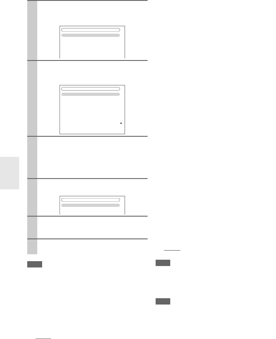
78
En
Note
• This procedure can also be performed on the AV controller by
using Setup, arrows, and Enter.
■MAC Address
This is the AV controller’s MAC (Media Access Control)
address. This address cannot be changed.
■DHCP
This setting determines whether or not the AV controller
uses DHCP to automatically configure its IP Address,
Subnet Mask, Gateway, and DNS Server settings.
`Enable:
DHCP enabled.
`Disable:
DHCP disabled.
If you select “Disable”, you must configure the “IP
Address”, “Subnet Mask”, “Gateway”, and “DNS
Server” settings yourself.
■IP Address
If you set the “DHCP” setting to “Disable”, you must
specify an IP address. Enter a static IP address provided
by your ISP.
The IP address must be within the following ranges.
`Class A:
10.0.0.0 to 10.255.255.255
`Class B:
172.16.0.0 to 172.31.255.255
`Class C:
192.168.0.0 to 192.168.255.255
Most routers use Class C IP addresses.
■Subnet Mask
If you set the “DHCP” setting to “Disable”, you must
specify a subnet mask address.
Enter the subnet mask address provided by your ISP (typi-
cally: 255.255.255.0).
■Gateway
If you set the “DHCP” setting to “Disable”, you must
specify a gateway address.
Enter the gateway address provided by your ISP.
■DNS Server
If you set the “DHCP” setting to “Disable”, you must
specify a DNS server.
Enter the DNS server addresses provided by your ISP.
■Proxy URL
To use a Web proxy, enter its URL here.
■Proxy Port
If you’re using a Web proxy, enter a proxy port number
here.
■Control
This setting enables or disables control over the network.
`Enable:
Control over the network enabled.
`Disable:
Control over the network disabled.
Note
• When set to “Enable”, power consumption on standby mode
increases.
■Port Number
This is the network port used for control over the network.
Note
• Set the port number between from “49152” to “65535”.
2Use q/w to select “Hardware Setup”, and then
press Enter.
The “Hardware Setup” menu appears.
3Use q/w to select “Network”, and then press
Enter.
The “Network” screen appears.
4Use q/w to select the setting, and use e/r to set
them.
To enter an IP address, select the setting, and then
press Enter. The arrow can then be used to enter
numbers. Press Enter again to set the number.
The settings are explained below.
5When you’ve finished, press Return.
The save confirmation screen appears.
6Use q/w to select “Save”, and then press Enter.
When modifying network settings, after modifying it
is necessary to execute “Save”.
7When you’ve finished, press Setup.
The setup menu closes.
7. Hardware Setup
1. Remote ID
2. Multi Zone
3. Tuner
4. HDMI
5. Auto Power Down
6. Network
7. Firmware Update
7-6. Network
MAC Address
DHCP
IP Address
Subnet Mask
Gateway
DNS Server
Proxy URL
Proxy Port
xx : xx : xx − yy : yy : yy
Enable
aaa.bbb.ccc.ddd
aaa.bbb.ccc.ddd
aaa.bbb.ccc.ddd
aaa.bbb.ccc.ddd
8080
Save
Cancel
7-6. Network
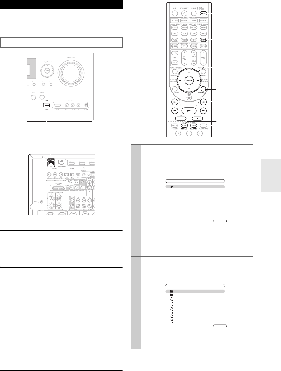
79
En
USB can be used to play music files stored on USB mass
storage devices (e.g., USB flash drives and MP3 players),
which can be plugged into the AV controller’s USB port.
Supported Audio File Formats
For USB mass storage device playback, the AV controller
supports music file formats.
See “Supported Audio File Formats” (➔75).
USB Mass Storage Device Requirements
• The AV controller supports USB devices that support the
USB mass storage device class.
• Playback may not be possible with some USB devices
even if they conform to the USB mass storage device
class.
• USB devices formatted with the FAT16 or FAT32 file
system are supported.
• If the storage device has been partitioned, each section
will be treated as an independent device.
• Each folder may contain up to 20000 music files and
folders, and folders may be nested up to 16 levels deep.
• USB hubs and USB devices with hub functions are not
supported.
Playing Music Files on a USB Device
This section explains how to play music files on a USB
mass storage device.
About USB
See “Controlling iPod” for iPod connection (➔87).
USB port
USB port 1Plug your USB mass storage device into the AV
controller’s USB port.
2Press NET/USB repeatedly to select the
“USB(Front)” or “USB(Rear)” screen.
The USB indicator lights (➔9) if the AV controller
is able to read the USB mass storage device. The
USB indicator flashes if the AV controller cannot
read the USB mass storage device.
3Use q/w to select a USB mass storage device, and
then press Enter.
A list of the device’s contents appears.
To open a folder, use q/w to select it, and then press
Enter.
NET/USB
Display
Enter
q/w/e/r
Return
1, 3, 2, 5,
4, 7, 6
Random
Repeat
USB(Front)
USB Storage
1 / 1
USB Storage
Folder1
Folder2
01_Song_Track1
02_Song_Track2
03_Song_Track3
04_Song_Track4
05_Song_Track5
06_Song_Track6
07_Song_Track7
08_Song_Track8
1 / 10
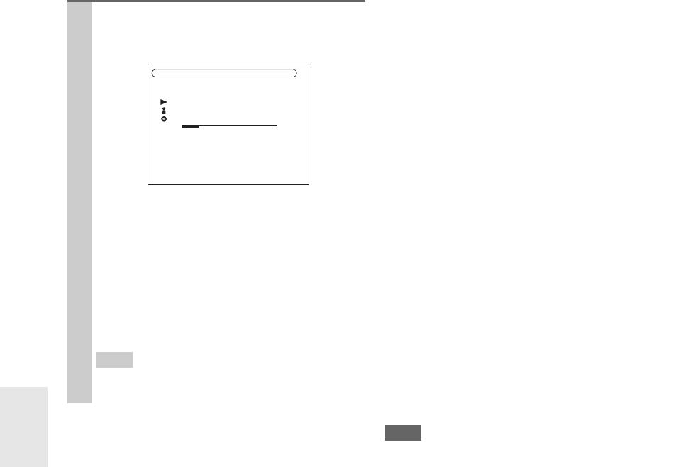
80
En
Random Playback
The Random function can only be set while the PLAY
screen is displayed.
To play songs in random order, while the list of songs is
displayed, press Random. All of the songs in the current
folder will be played in random order. When all of the
songs in the folder have been played once, they’ll all be
played again in a different random order. To cancel ran-
dom playback, press Random again.
Random playback supports up to 20,000 songs per folder.
If a folder contains more than this, songs over 20,000 are
not included in random playback.
Repeat Playback
The Repeat function can only be set while the PLAY
screen is displayed.
To play songs repeatedly, during playback (or while play-
back is paused or stopped), press Repeat repeatedly to
select: Repeat1, Repeat Folder, Repeat All, or Off.
In Repeat1 mode, the current song is played repeatedly.
In Repeat Folder mode, all of the songs in the current
folder are played repeatedly.
In Repeat All mode, all of the songs on the USB mass
storage device (in the same partition) are played repeat-
edly.
To cancel repeat playback, press Repeat repeatedly to
select Off.
Note
• If you connect a USB hard disk drive to the AV controller’s USB
port, we recommend that you use its AC adapter to power it.
• Do not connect the AV controller’s USB port to a USB port on
your computer. Music on your computer cannot be played
through the AV controller in this way.
• The AV controller supports USB MP3 players that support the
USB Mass Storage Class standard, which allows USB storage
devices to be connected to computers without the need for spe-
cial drivers or software. Note that not all USB MP3 players sup-
port the USB Mass Storage Class standard. Refer your USB
MP3 player’s instruction manual for details.
• Protected WMA music files on an MP3 player cannot be played.
• Onkyo accepts no responsibility whatsoever for the loss or dam-
age to data stored on a USB mass storage device when that
device is used with the AV controller. We recommend that you
back up your important music files beforehand.
• The AV controller does not support MP3 players containing
music files that are managed with special music software.
• Operation with all USB mass storage devices including the abil-
ity to power them is not guaranteed.
• Do not connect your USB mass storage device via a USB hub.
The USB mass storage device must be connected directly to the
AV controller’s USB port.
• If the USB mass storage device contains a lot of data, the AV
controller make take a while to read it.
• USB memory devices with security functions cannot be played.
4Use q/w to select a music file, and press Enter or
1 to start playback.
Playback starts and the following screen appears.
• To return to the previous menu during playback,
press Return.
• To stop or pause playback, press 2 or 3, respec-
tively.
• To select the next song, press 6. To select the
beginning of the current song, press 7. To select
the previous song, press 7 twice.
• To fast forward the current song, press 4. To
fast reverse the current song, press 5.
Tip
• If you press Display, you can toggle between the play-
back screen and the list screen.
00:10
01:12:34
Folder1
Album
Artist
02_Song_Track2
MP3 128kbps 16bit/44.1kHz
1/17
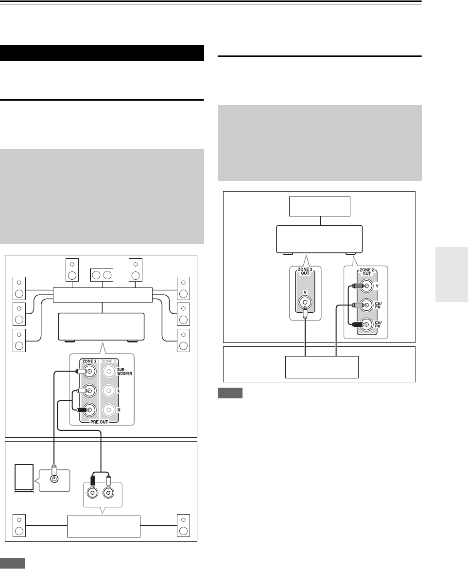
81
En
Multi Zone
In addition to your main listening room, you can also enjoy playback in the other room, or as we call Multi Zone. And,
you can select a different source for each room.
Zone 2 speakers must be connected to an amp in Zone 2.
Connecting Your Zone 2 Speakers
You can enjoy 2-channel stereo playback in Zone 2 and a
different source to those selected for your main room and
Zone 3.
Note
• With the default settings, the Zone 2 volume must be set on the
Zone 2 amp. If your Zone 2 amp has no volume control, set the
“Zone 2 Out” setting to “Variabl e” so that you can set the
Zone 2 volume on the AV controller (➔82).
Zone 2 Video Output
The AV controller features a composite video output for
connection to a TV in Zone 2, so you can enjoy both audio
and video in that zone.
Note
• If you use the COMPONENT VIDEO ZONE 2 OUT, you must
set the “Zone 2 Component Out” setting to “Use” (➔82).
•The COMPONENT VIDEO ZONE 2 OUT outputs video only
from components connected to component video inputs.
•The ZONE 2 OUT V jack outputs video from components con-
nected to composite video inputs.
Connecting Zone 2
Hookup
• Use an RCA audio cable to connect the AV controller’s PRE
OUT ZONE 2 L/R jacks to an analog audio input on your
Zone 2 amp.
• Use an RCA audio cable to connect the AV controller’s PRE
OUT ZONE 2 SUBWOOFER jack to the line input on a
powered subwoofer in Zone 2.
• Connect your Zone 2 speakers to the speaker terminals on
your Zone 2 amp.
RL
IN
LINE INPUT
Main room
Zone 2
AV controller
Powered subwoofer
Receiver/
integrated amp
Multichannel power amp
Hookup
• Use a composite video cable to connect the AV controller’s
ZONE 2 OUT V jack to a composite video input on your
Zone 2 TV.
• Alternatively, use a component video cable to connect the AV
controller’s COMPONENT VIDEO ZONE 2 OUT jacks to
a component video input on your Zone 2 TV.
Main room
TV
Zone 2
AV controller
TV
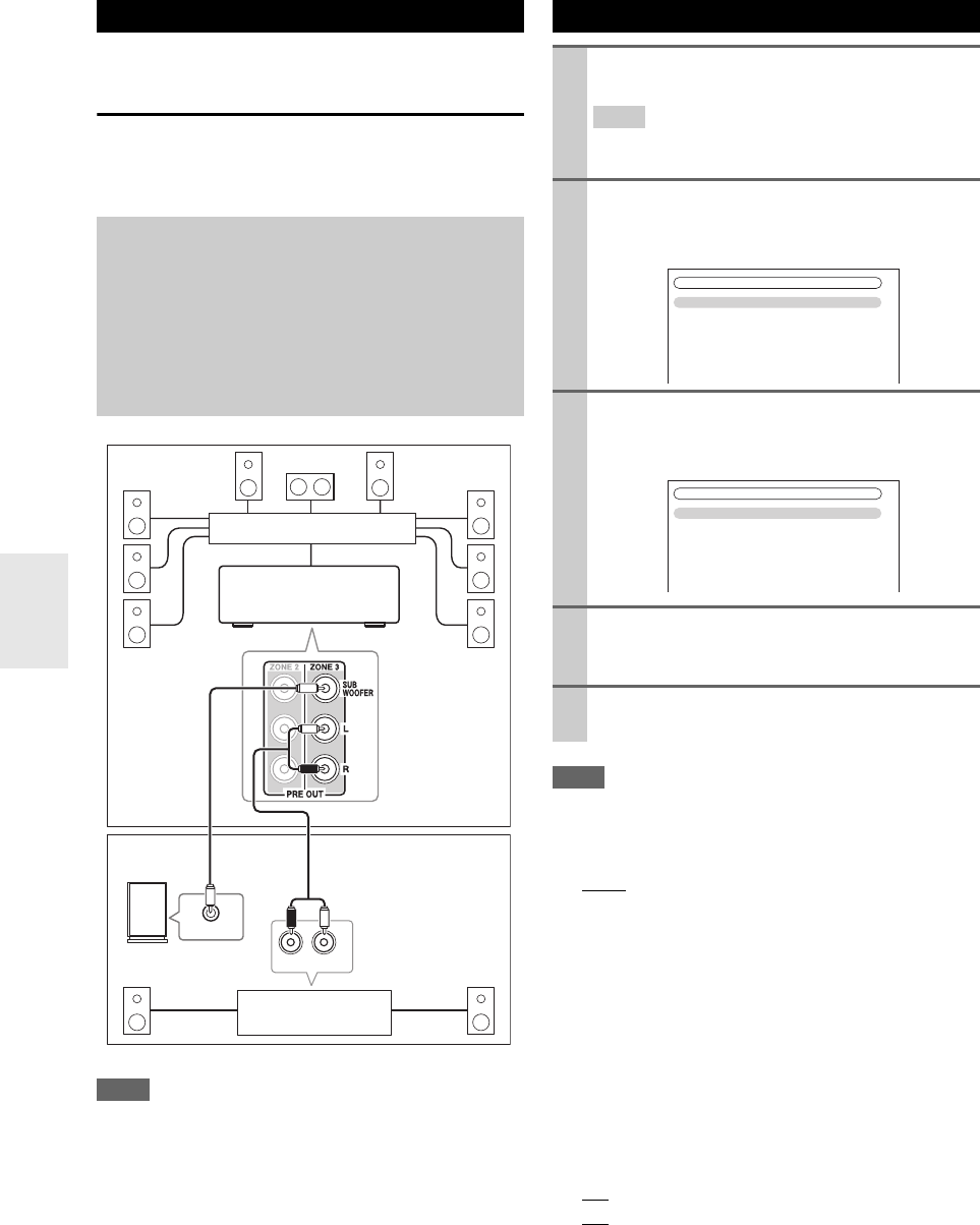
82
En
Zone 3 speakers must be connected to an amp in Zone 3.
Connecting Your Zone 3 Speakers
You can enjoy 2-channel stereo playback in Zone 3 and a
different source to those selected for your main room and
Zone 2.
Note
• With the default settings, the Zone 3 volume must be set on the
Zone 3 amp. If your Zone 3 amp has no volume control, set the
“Zone 3 Out” setting to “Variable” so that you can set the
Zone 3 volume on the AV controller.
Note
• This procedure can also be performed on the AV controller by
using Setup, arrows, and Enter.
■Zone 2 Out, Zone 3 Out
`Fixed:
The Zone 2/3 volume must be set on the amp in that
zone.
`Vari able:
The Zone 2/3 volume can be set on the AV control-
ler.
If you’ve connected your Zone 2/3 speakers to an amp
with no volume control, set the “Zone 2 Out” and
“Zone 3 Out” setting, respectively, to “Var iable” so that
you can set the volume, balance, and tone of Zone 2/3 on
the AV controller.
■Zone 2 Maximum Volume,
Zone 3 Maximum Volume
`Off, 50 to 99 (Absolute display)
`Off, –32dB to +17dB (Relative display)
With this setting, you can limit the maximum volume for
Zone 2/3.
Connecting Zone 3
Hookup
• Use an RCA audio cable to connect the AV controller’s PRE
OUT ZONE 3 L/R jacks to an analog audio input on your
Zone 3 amp.
• Use an RCA audio cable to connect the AV controller’s PRE
OUT ZONE 3 SUBWOOFER jack to the line input on a
powered subwoofer in Zone 3.
• Connect your Zone 3 speakers to the speaker terminals on
your Zone 3 amp.
RL
IN
LINE INPUT
Main room
Zone 3
AV controller
Powered subwoofer
Receiver/
integrated amp
Multichannel power amp
Setting the Multi Zone
1Press Receiver followed by Setup.
The main menu appears onscreen.
Tip
• If the main menu doesn’t appear, make sure the appropri-
ate external input is selected on your TV.
2Use q/w to select “Hardware Setup”, and then
press Enter.
The “Hardware Setup” menu appears.
3Use q/w to select “Multi Zone”, and then press
Enter.
The “Multi Zone” menu appears.
4Use q/w to select an item, and use e/r to change
it.
The items are explained below.
5Press Setup.
The setup menu closes.
7. Hardware Setup
1. Remote ID
2. Multi Zone
3. Tuner
4. HDMI
5. Auto Power Down
6. Network
7. Firmware Update
7-2. Multi Zone
Zone 2 Out
Zone 2 Maximum Volume
Zone 2 Power On Volume
Zone 2 Component Out
Zone 3 Out
Zone 3 Maximum Volume
Zone 3 Power On Volume
Fixed
Off
Last
Use
Fixed
Off
Last
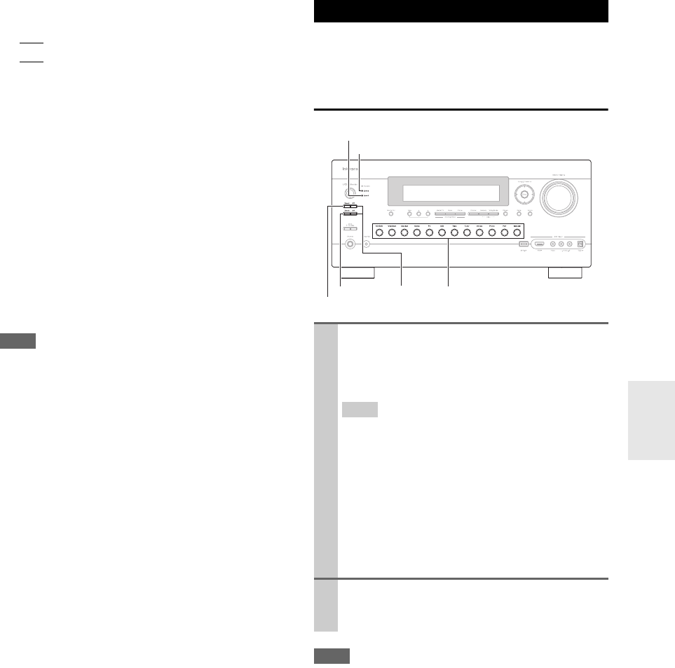
83
En
■Zone 2 Power On Volume,
Zone 3 Power On Volume
`Last, Min, 1 to 99 or Max (Absolute display)
`Last, –QdB, –81dB to +18dB (Relative display)
This setting determines what the volume will be for
Zone 2/3 each time the AV controller is turned on.
To use the same volume level as when the AV controller
was last turned off, select “Last”.
The “Zone 2 Power On Volume” and “Zone 3 Power On
Volume” cannot be set higher than the “Zone 2 Maxi-
mum Volume” and “Zone 3 Maximum Volume” setting.
■Zone 2 Component Out
`Use:
Select if a TV in Zone 2 is connected the COMPO-
NENT VIDEO ZONE 2 OUT.
`Not Use:
Select if no TV in Zone 2 is connected the COMPO-
NENT VIDEO ZONE 2 OUT.
If you’ve connected the COMPONENT VIDEO ZONE 2
OUT to a TV in Zone 2, this setting is set to “Use”.
Note
If the “Zone 2 Component Out” setting is set to “Not
Use”, the same video signal as COMPONENT VIDEO
MONITOR OUT is output from ZONE 2 OUT (compo-
nent).
This section explains how to turn Zone 2/3 on and off,
how to select an input source for Zone 2/3, and how to
adjust the volume for Zone 2/3.
Controlling Zone 2/3 from the AV Controller
Note
• When Zone 2/3 is turned off, the output from the 12V TRIG-
GER OUT goes low (0 volts).
Using Zone 2/3
1To turn on Zone 2/3 and select an input source,
press Zone 2 or Zone 3 followed by an input
selector button within 8 seconds.
Zone 2/3 turns on, the Zone 2/3 indicator lights.
Tip
•The 12V TRIGGER OUT goes high (+12 V).
To select AM or FM, press Tuner input selector and
Zone 2 or Zone 3 repeatedly.
(North American models) You can also select SIR-
IUS.
To select the same source as that of the main room,
press Zone 2 or Zone 3 twice. “Zone2 Selector:
Source” or “Zone3 Selector: Source” appears on
the display.
2To turn off Zone 2/3, press Off for each Zone.
The zone is turned off, and the Zone 2 or Zone 3
indicator goes off.
Zone 3
Zone 2
Off
Zone 2 indicator
Input selector buttons
Zone 3 indicator
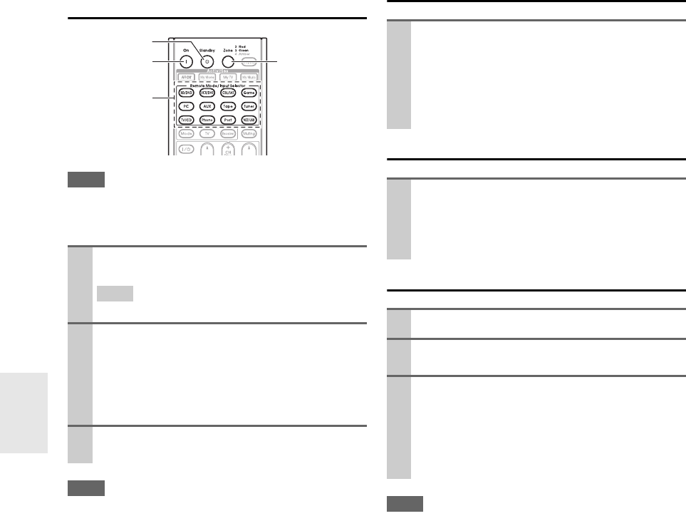
84
En
Controlling Zone 2/3 with the Remote
Controller
Note
• To control Zone 2/3, you must press the remote controller’s
Zone first.
•Zone turns red while Zone 2 is on, and green while Zone 3 is on.
Note
• Only analog input sources are output by the ZONE 2/3 PRE
OUT jacks. Digital input sources are not output. If no sound is
heard when an input source is selected, check if it’s connected to
an analog input.
• You cannot select different AM or FM radio stations for your
main room and Zone 2/3. The same AM/FM radio station will be
heard in each room. For example, if you have an FM station for
the main room, that station will also be used in Zone 2.
• When the input selector of Zone 2/3 is selected, power consump-
tion on standby mode slightly increases.
• While Zone 2/3 is on, u functions will not work.
Adjusting the Volume for Zones
Muting Zones
Adjusting the Tone and Balance of Zones
Note
• Zones can also be unmuted by adjusting the volume.
• The Zone 2 volume, tone, and balance function have no effect on
ZONE 2 PRE OUT when the “Zone 2 Out” setting is set to
“Fixed” (➔82).
• The Zone 3 volume, tone, and balance function have no effect on
ZONE 3 PRE OUT when the “Zone 3 Out” setting is set to
“Fixed” (➔82).
• Even if you repeatedly press the remote controller’s Zone to
select zones, the last zone selection will be retained once you
have switched to other components by pressing other Remote
Mode after pressing Zone.
1Press Zone repeatedly, then point the remote con-
troller at the AV controller and press On.
Tip
•The 12V TRIGGER OUT goes high (+12 V).
2To select an input source for Zone 2/3, press Zone
repeatedly, followed by Input Selector.
To select AM or FM, press Tuner input selector and
Zone repeatedly.
(North American models) You can also select SIR-
IUS.
3To turn off Zone 2/3, press Zone repeatedly, fol-
lowed by Standby.
Input
Selector
On Zone
Standby
On the remote controller, press Zone repeatedly,
and then use VOL q/w.
On the AV controller, press Zone 2 or Zone 3
(the Zone 2/3 indicator and Zone 2/3 selector on
the display flashes) and press Zone Level w/q
within 8 seconds.
On the remote controller, press Zone repeatedly,
and then press Muting.
To unmute a zone, on the remote controller, press
Zone, and then press Muting again.
1On the AV controller, press Zone 2 or Zone 3.
2Press the AV controller’s Tone repeatedly to select
“Bass”, “Treble” or “Balance”.
3Use –/+ to adjust the bass, treble or balance.
• You can boost or cut the bass or treble from –10 dB
to +10 dB in 2 dB steps.
• You can adjust the balance from 0 in the center to
+10 dB to the right or +10 dB to the left in 2 dB
steps.
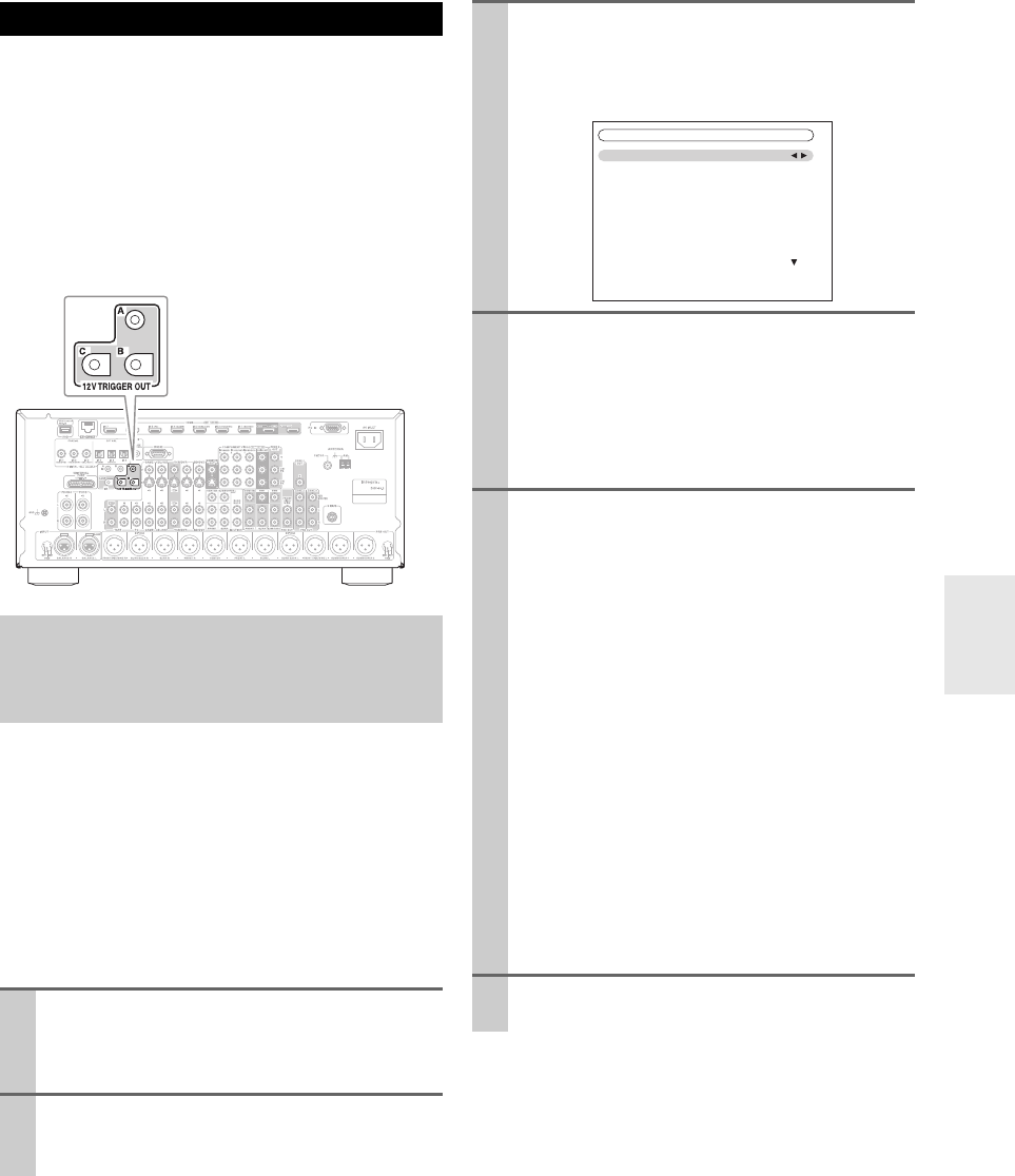
85
En
The 12V triggers A, B, and C can be used to turn on 12V
trigger-capable components automatically when they are
selected as the input source. The triggers can be set so that
they activate when a connected component is selected as
the input source for the main room, Zone 2, Zone 3 or any
combination of rooms.
When triggered, the output from a 12V TRIGGER OUT
goes high (+12 volts and 150 milliamperes max. at TRIG-
GER OUT A; +12 volts and 25 milliamperes max. at
TRIGGER OUT B and C).
When several components are turned on simultaneously
by using triggers A, B, and C, depending on the type of
components, a large amount of current may be drawn
momentarily. To prevent this, you can delay trigger signals
A, B, and C individually. Another application for trigger
delay is eliminating the “thump” noise that’s sometimes
heard when a source component is turned on.
Delaying the trigger signal for your power amplifier so
that it’s the last component to be turned on will accom-
plish this.
Using the 12V Triggers
Hookup
• Use a miniplug cable to connect the AV controller’s
12V TRIGGER OUT A, B, or C jack to the 12 V trigger
input on a connected component.
1Press Receiver followed by Setup.
The main menu appears onscreen.
If the main menu doesn’t appear, make sure the
appropriate external input is selected on your TV.
2Use q/w to select “Miscellaneous” and then press
Enter.
The “Miscellaneous” menu appears.
3Use q/w to select “12V Trigger A, B, or C Setup”
and then press Enter.
The “12V Trigger A, B, or C Setup” screen
appears.
4Use q/w to select “Delay”, and use e/r to select:
`0sec (Trigger A: default),
1sec (Trigger B: default),
2sec (Trigger C: default),
or 3sec.
When “0sec” is selected, the trigger signal is output
as soon as the input source is changed.
5Use q/w to select an input source, and use e/r to
select an option.
`Off:
No trigger signal is output.
A 12-volt trigger signal is output when the connected
component is selected as the source for:
`Main (Trigger A: default):
Main room.
`Zone 2 (Trigger C: default):
Zone 2.
`Main/Zone 2:
Main room or Zone 2.
`Zone 3:
Zone 3.
`Main/Zone 3:
Main room or Zone 3.
`Zone 2/Zone 3:
Zone 2 or Zone 3.
`Main/Zone 2/Zone 3 (Trigger B: default):
Main room, Zone 2, or Zone 3.
6When you’ve finished, press Setup.
The setup menu closes.
6-3. 12V Trigger A Setup
Delay
BD/DVD
VCR/DVR
CBL/SAT
GAME
PC
AUX
0sec
Main
Main
Main
Main
Main
Main
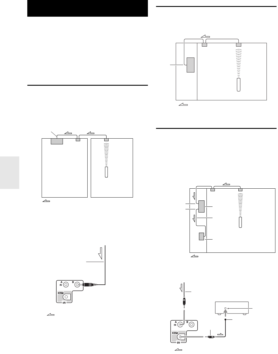
86
En
To control the AV controller with the remote controller
while you’re in Zone 2 or Zone 3, you’ll need a commer-
cially available multiroom remote control kit for each
zone.
• Multiroom kits are made by Niles and Xantech.
These kits can also be used when there isn’t a clear line of
sight to the AV controller’s remote sensor, such as when
it’s installed inside a cabinet.
Using a Multiroom Kit with Zone 2/3
In this setup, the IR receiver in Zone 2/3 picks up the
infrared signals from the remote controller and feeds them
through to the AV controller in the main room via the con-
necting block.
The miniplug cable from the connecting block should be
connected to the AV controller’s IR IN A or B jack, as
shown below. The IR IN A and B jacks are identical. Up
to two IR receivers can be connected.
Using a Multiroom Kit with a Cabinet
In this setup, the IR receiver picks up the infrared signals
from the remote controller and feeds them to the AV con-
troller located in the cabinet via the connecting block.
Using a Multiroom Kit with Other
Components
In this setup, an IR emitter is connected to the AV control-
ler’s IR OUT jack and placed in front of the other compo-
nent’s remote control sensor. Infrared signals received at
the AV controller’s IR IN A or B jack are fed through to
the other component via the IR emitter. Signals picked up
by the AV controller’s remote control sensor are not out-
put.
The IR emitter should be connected to the AV controller’s
IR OUT jack, as shown below.
Using the Remote Controller in
Zone 2/3 and Multiroom Control Kits
Connect-
ing block
Remote controller
IR receiver
Main room Zone 2/3
Signal flow
IR IN A or B
From the connecting block
Miniplug cable
AV controller
Signal flow
IR IN
Connecting
block
Remote controller
IR receiver
Inside
cabinet
Signal flow
Connecting
block
IR receiver
Remote controller
Signal flow
IR Emitter
Other component
AV controller
IR IN A or B
IR OUT
Remote con-
trol sensor
Other component
Emitter
IR Emitter
Signal flow
Miniplug
Miniplug cable
AV controller
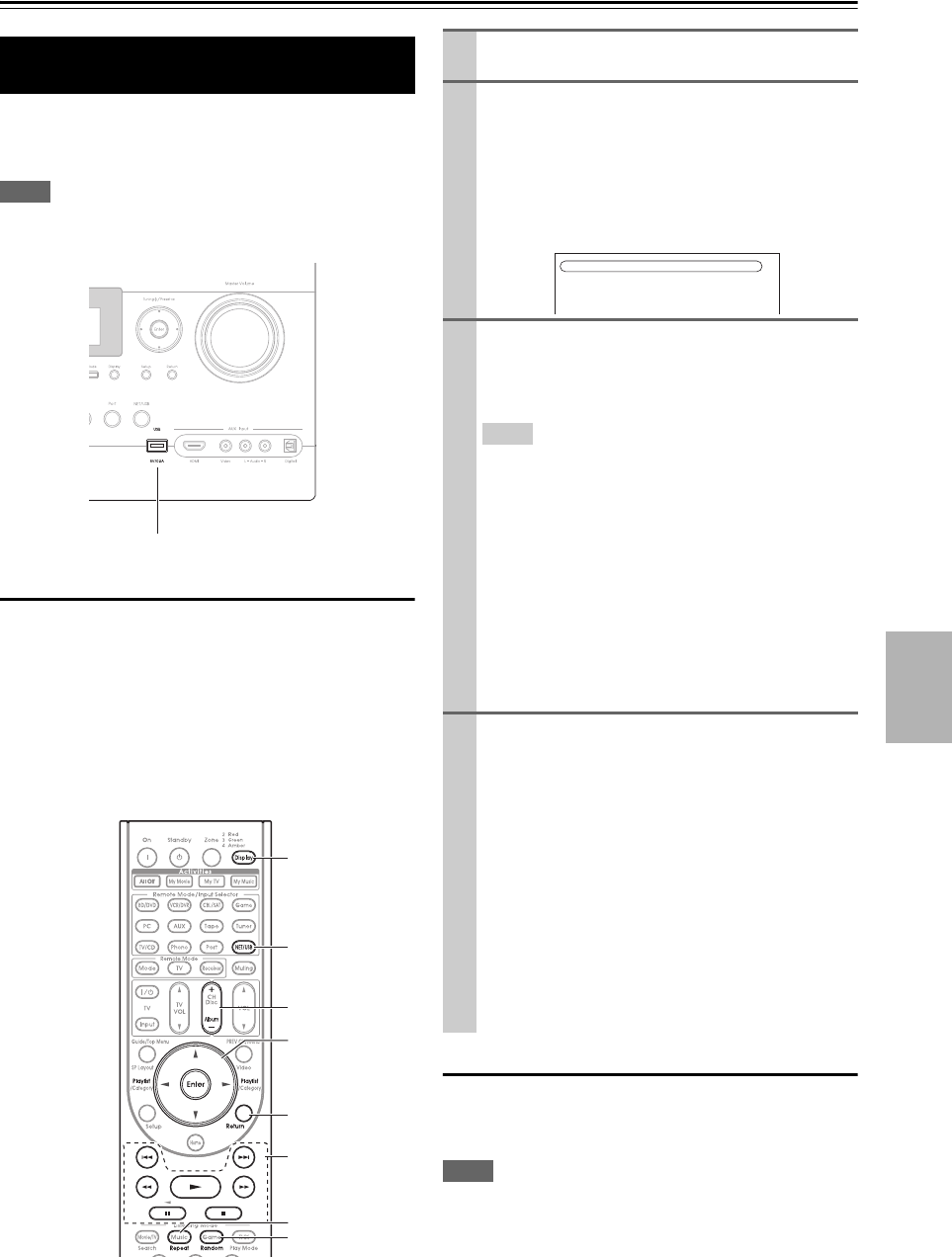
87
En
Controlling iPod & Other Components
Controlling iPod
USB can be used to play music files stored on
iPod/iPhone, which can be plugged into the AV control-
ler’s USB port.
Note
• Note that the rear-panel USB port does not support iPod/iPhone
connection.
Playing Music Files on the iPod/iPhone
This section explains how to play music files on the
iPod/iPhone*1.
*1 Compatible iPod models
Standard Mode control
The content information is not displayed onscreen, but can
be manipulated using the iPod/iPhone or the Remote Con-
trol.
Note
• The audio of video content can be played back but no video will
be displayed onscreen.
Connecting the iPod Directly to the
USB Port
Made for:
• iPod touch (1st and 2nd generation)
• iPod classic
• iPod (5th generation)
• iPod nano (1st, 2nd, 3rd, 4th and 5th generation)
• All iPhone models
USB port
NET/USB
Return
1, 3, 2, 5,
4, 7, 6
Random
Display
Album +/–
Repeat
q/w, Enter,
Playliste/r
1Press NET/USB repeatedly to select the USB
input.
2Connect the USB cable that comes with the
iPod/iPhone to the USB port at the front of the AV
controller.
• The USB indicator lights (➔9) if the AV control-
ler is able to read the iPod/iPhone.
• The USB indicator flashes if the AV controller can-
not read the iPod/iPhone.
3Press Display to switch to Extended Mode*3.
A list of your iPod model’s contents appears. To
open a folder, use q/w to select it, and then press
Enter.
Tip
• With the default settings, the iPod/iPhone can be manipu-
lated in Standard Mode*2.
• Pressing Display again switches back to Standard Mode.
*2 The following iPod models are not supported in Stan-
dard Mode. These iPod models can only be controlled
in Extended Mode.
• iPod (5th generation)
• iPod nano (1st generation)
*3 When you disconnect the iPod/iPhone, the AV control-
ler stores the mode. This means that if you disconnect
when in Extended Mode, the AV controller will start in
Extended Mode when you next connect the
iPod/iPhone.
4Use q/w to select a music file, and press Enter or
1 to start playback.
• To return to the previous menu during playback,
press Return.
• To stop or pause playback, press 2 or 3, respec-
tively.
• To select the next song, press 6. To select the
beginning of the current song, press 7. To select
the previous song, press 7 twice.
• To fast forward the current song, press 4. To
fast reverse the current song, press 5.
• To switch the repeat mode, press Repeat. To
switch the random mode, press Random.
iPod(STD)
Push “DISPLAY” button to switch to Extended mode.
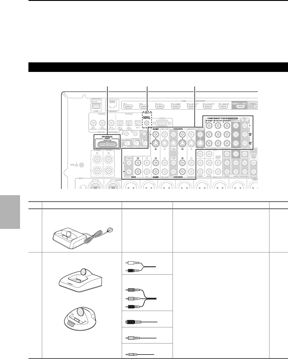
88
En
Extended Mode control
The content information is displayed (lists are displayed)
on the on-screen, and you can select and manipulate the
content while looking at the screen.
Top screen list:
• Playlists*4
• Artists*4
•Albums
*4
•Genres
*4
• Songs*4
•Composers
*4
• Shuffle Songs*5
•Now Playing
*6
*4 Displays a list.
*5 Plays all tracks in random order.
*6 Displays information about currently playing track.
Models sold are different depending on the region.
Connecting an Onkyo Dock
No. Onkyo Dock Cable Note Page
AUP-A1 Dock
(Universal Port Option Dock)
— • When UP-A1 Dock that seated iPod is con-
nected, the power consumption on standby
mode slightly increases.
• You can control your iPod when “Port” is
selected as the input source.
• See the UP-A1 Dock’s instruction manual for
more information.
89
BRI Dock Analog audio (RCA) • See the RI Dock’s instruction manual for more
information.
*1 To use u (Remote Interactive), you must
make an analog audio connection (RCA)
between the AV controller and the RI Dock.
89
Component video
S-Video
Composite video
u cable*1
*1
AB
Y
PB/CB
PR/CR

89
En
UP-A1 Dock
With the UP-A1 Dock, you can easily play the music,
photo, or movie stored on your Apple iPod through the AV
controller and enjoy great sound.
You can use the AV controller’s remote controller to oper-
ate your iPod.
■Basic Operation
Auto Power On
If you start iPod playback while the AV controller is on
Standby, the AV controller will automatically turn on and
select your iPod as the input source.
Direct Change
If you start iPod playback while listening to another input
source, the AV controller will automatically select your
iPod as the input source.
Using the AV controller’s Remote Controller
You can use the AV controller’s remote controller to con-
trol basic iPod functions (➔90).
■Using Your iPod models Alarm Clock
You can use your iPod models Alarm Clock function to
automatically turn on your iPod and the AV controller at a
specified time. The AV controller’s input source will auto-
matically be set to the Port selector.
Note
• To use this function, your iPod must be in the UP-A1 Dock, and
the UP-A1 Dock must be connected to the AV controller.
• This function works only in the Standard mode (➔91).
• When you use this function, be sure to set the AV controller’s
volume control to a suitable level.
• When Zone 2 or 3 is turned on, you can’t use this function.
• You cannot use this function for sound effects on your
iPod/iPhone.
■Charging Your iPod models Battery
The UP-A1 Dock charges your iPod models battery while
your iPod is in the UP-A1 Dock and connected to the
UNIVERSAL PORT jack on the AV controller. While
your iPod is seated in the UP-A1 Dock, its battery will be
charged when the AV controller is set to “On” or
“Standby”.
Note
• When UP-A1 Dock that seated iPod is connected, the power
consumption on standby mode slightly increases.
■Status Messages
• PORT Reading
The AV controller is checking the connection with the
dock.
• PORT Not Support
The AV controller do not support the connected dock.
•PORT UP-A1
UP-A1 Dock is connected.
Note
• The AV controller displays the message “UP-A1” for several
seconds after recognizing the UP-A1.
• When the status message is not displayed on the AV controller’s
display, check the connection to your iPod.
RI Dock
With the RI Dock, you can easily play the music stored on
your Apple iPod through the AV controller and enjoy great
sound, and watch iPod slideshows and videos on your TV.
In addition, the onscreen display (OSD) allows you to
view, navigate, and select your iPod model’s contents on
your TV, and with the supplied remote controller, you can
control your iPod from the comfort of your sofa. You can
even use the AV controller’s remote controller to operate
your iPod.
Note
• Enter the appropriate remote control code before using the AV
controller’s remote controller for the first time (➔94).
• Connect the RI Dock to the AV controller with an u cable
(➔88).
• Set the RI Dock’s RI MODE switch to “HDD” or
“HDD/DOCK”.
• Set the AV controller’s Input Display to “DOCK” (➔28).
Using the Onkyo Dock
Dock is sold separately.
For the latest information on the Onkyo Dock compo-
nents, see the Onkyo web site at:
http://www.onkyo.com
Before using the Onkyo Dock components, update
your iPod with the latest software, available from the
Apple web site.
For supported iPod models, see the instruction man-
ual of the Onkyo Dock.
The AV controller may take several seconds to startup,
so you might not hear the first few seconds of the first
song.
■Operating Notes
• Functionality depends on your iPod model and generation.
• Before selecting a different input source, stop iPod playback
to prevent the AV controller from selecting the iPod input
source by mistake.
• If any accessories are connected to your iPod, the AV control-
ler may not be able to select the input source properly.
• When connecting UP-A1 Dock to the radio tuner UP-HT1
(North American models)/UP-DT1 (Australian models)
with AUTO selected by the tuner’s Mode Selector switch, you
can switch the input source between UP-A1 Dock and the
tuner, by pressing Port repeatedly on the front panel.
• While your iPod is in the UP-A1 Dock, its volume control has
no effect. If you adjust your iPod models volume control while
it’s in the UP-A1 Dock, make sure it’s not set too high before
you reconnect your headphones.
• The Auto Power On function will not work if you set your
iPod in the UP-A1 Dock while it is playing.
• When Zone 2 or 3 is turned on, you can’t use Auto Power On
and Direct Change functions.
• Do not turn off the power with the iPod still connected to this
unit via the UP-A1 Dock.
• Set your iPod in the UP-A1 Dock after the AV controller turns
on.

90
En
■System Function
Auto Power On
If you press the remote controller’s 1 while the AV con-
troller is on Standby, the AV controller will automatically
turn on, select your iPod as the input source, and your
iPod will start playback.
Direct Change
If you start iPod playback while listening to another input
source, the AV controller will automatically switch to the
input to which the RI Dock is connected.
Using the AV controller’s Remote Controller
You can use the AV controller’s remote controller to con-
trol basic iPod functions.
Using Your iPod models Alarm Clock
If you use the Alarm Clock function on your iPod to start
playback, the AV controller will automatically turn on at
the specified time and select your iPod as the input source.
System Off
When you turn off the AV controller, the RI Dock and
iPod turn off automatically.
Note
• Linked operations do not work with video playback or when the
alarm is set to play a sound.
• If you use your iPod with any other accessories, iPod playback
detection may not work.
• This function works only in the Standard mode (➔91).
Note
• On the 5th generation iPod and iPod nano, the click wheel is
disabled during playback.
By pressing Remote Mode that’s been programmed with
the remote control code for your Dock, you can control
your iPod in the Dock.
See “Entering Remote Control Codes” for details on
entering a remote control code (➔94).
See the Dock’s instruction manual for more information.
■UP-A1 Dock
Port is preprogrammed with the remote control code for
controlling a Dock with Universal Port connector.
You can control your iPod when “Port” is selected as the
input source.
Without the RI Control
You must enter a remote control code 82990 first (➔94).
■RI Dock
• Set the RI Dock’s RI MODE switch to “HDD” or
“HDD/DOCK”.
•On/Standby may not work with a remote control code
(without u). In this case, make an u connection and
enter a remote control code 81993 (with u).
With the RI Control
In this case, make an u connection and enter a remote
control code 81993 (with u).
• Set the AV controller’s Input Display to “DOCK”
(➔28).
■Operating Notes
• Use the AV controller’s volume control to adjust the playback
volume.
• While your iPod is inserted in the RI Dock, its volume con-
trol has no effect. If you adjust your iPod models volume
control while it’s in the UP-A1 Dock, make sure it’s not set
too high before you reconnect your headphones.
Controlling Your iPod
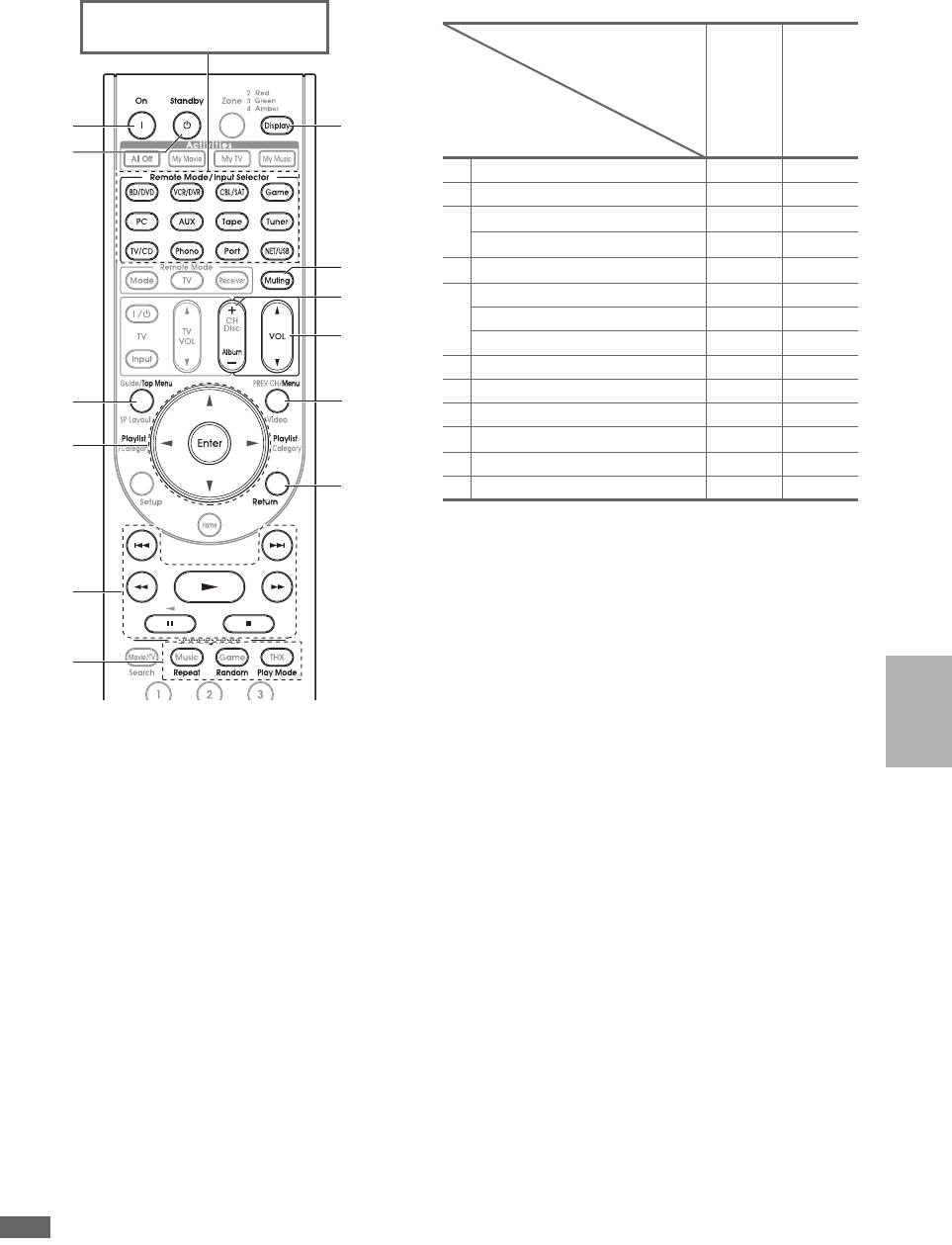
91
En
✔: Available buttons
• With some iPod models, generations and RI Docks, certain buttons may not work as expected.
• For detailed operation of the iPod, please refer to the instruction manual of RI Dock.
*1 This button does not turn the Onkyo DS-A2 or DS-A2X RI Dock on or off. Your iPod may not respond the first time you press this
button, in which case you should press it again.
This is because the remote controller transmits the On and Standby commands alternately, so if your iPod is already on, it will
remain on when the remote controller transmits an On command.
Similarly, if your iPod is already off, it will remain off when the remote controller transmits an Off command.
*2 Press Display to change the following modes:
Standard mode
Nothing is displayed on your TV and you navigate and select your contents by using your iPod models display.
Only this mode can playback the video.
Extended mode (Music)
Playlists (artists, albums, songs, and so on) are displayed on your TV, and you can navigate and select your music while looking at
your TV.
Extended mode (Video)
Playlists (Movies, Music Videos, TV Shows, Video Podcasts, or Rentals) are displayed on your TV, and you can navigate and select
your video while looking at your TV.
*3 In Extended mode (see *2), Playlist is used as the page jump button.
With the page modes, you can quickly locate your favorite songs even when your song lists, artist lists, and so on are very long.
*4 Resume mode
With the Resume function, you can resume playback of the song that was playing when you removed your iPod from the RI Dock or
Extended mode is selected.
*5 Top Menu works as a Mode button when used with a DS-A2 RI Dock.
*6 Display turns on backlight for 30 seconds.
Note
• In Extended mode (see *2), the playback will be continued even if the AV controller is turned off.
• In Extended mode (see *2), you cannot operate your iPod directly.
• In Extended mode (see *2), it may take some time to acquire the contents.
b
c
a
a
f
d
e
g
i
h
k
j
Press the appropriate Remote
Mode first.
UP-A1 Dock
u Dock
aOn, Standby ✔*1
bTop Menu ✔*5
cq/w/e/rEnter ✔✔
Playlist e/r✔*3 ✔
d1, 3, 2, 5, 4, 7, 6✔✔
eRepeat ✔✔
Random ✔✔
Play Mode ✔*4 ✔*4
fDisplay*6 ✔*2 ✔
gMuting ✔✔
hAlbum +/– ✔✔
iVOL q/w✔✔
jMenu ✔
kReturn ✔
Onkyo Dock
Buttons
92
En
Controlling Other Components
You can use the AV controller’s remote controller
(RC-772M) to control your other AV components, includ-
ing those made by other manufacturers. This section
explains how to enter the remote control code (with the
default underlined) for a component that you want to con-
trol: DVD, TV, CD, etc.
• Learn commands directly from another component’s
remote controller (➔98).
• Program Activities to perform a sequence of up to 32
remote control actions (➔97, 99).
The following Remote Mode are preprogrammed with
remote control codes for controlling the components
listed. You do not need to enter a remote control code to
control these components.
For details on controlling these components, see the pages
indicated.
You can look up for appropriate remote control code from
on-screen setup menu.
Note
• This setting can be carried out by using on-screen setup menu
only.
Preprogrammed Remote Control
Codes
BD/DVD Integra/Onkyo Blu-ray Disc player (➔95)
Tape Integra/Onkyo cassette tape deck with u
(➔96)
TV/CD Integra/Onkyo CD player (➔96)
Port Onkyo Universal Port Option (➔90)
Looking up for Remote Control Code
1Press Receiver followed by Setup.
The main menu appears onscreen.
Tip
• If the main menu doesn’t appear, make sure the appro-
priate external input is selected on your TV.
2Use q/w to select “Remote Controller Setup”,
and then press Enter.
The “Remote Controller Setup” menu appears.
3Use q/w to select “Remote Mode Setup”, and
then press Enter.
The “Remote Mode Setup” menu appears.
1. Remote Mode Setup
2. Activities Setup
8. Remote Controller Setup
TV
BD/DVD
VCR/DVR
CBL/SAT
GAME
PC
AUX
8–1. Remote Mode Setup
4Use q/w to select remote mode, and then press
Enter.
The category selection menu appears.
5Use q/w to select category, and then press
Enter.
The brand name input panel appears.
6Use q/w/e/r to select a character, and then
press Enter.
Repeat this step from the 1st character to the 3rd
character of the brand name.
When you have entered the 3rd character, select
“Search” and press Enter.
After searching, a list of the brand name appears.
7Use q/w to select the brand name, and press
Enter.
Go to step 8.
If you cannot find the brand name, use r to
select “Search DB”, and then press Enter to
access the database on the network.
The AV controller accesses and searches the data-
base. After searching, a list of the brand name
appears.
TV
TV/DVD
TV/VCR
8–1. Remote Mode Setup TV
ABCDEFGH I J KLM
NOPQRS TUVWXY Z
1234567890 &@
–
Space
Back Space
Search
8–1. Remote Mode Setup TV
Category
Brand
TV
8–1. Remote Mode Setup TV
TVCategory
Brand
Search DB
Sonawa
Sonber
Songba
Sonic
Soniko
8–1. Remote Mode Setup TV
TVCategory
Brand
Not Listed
Sonawa
Sonber
Songba
Sonic
Soniko
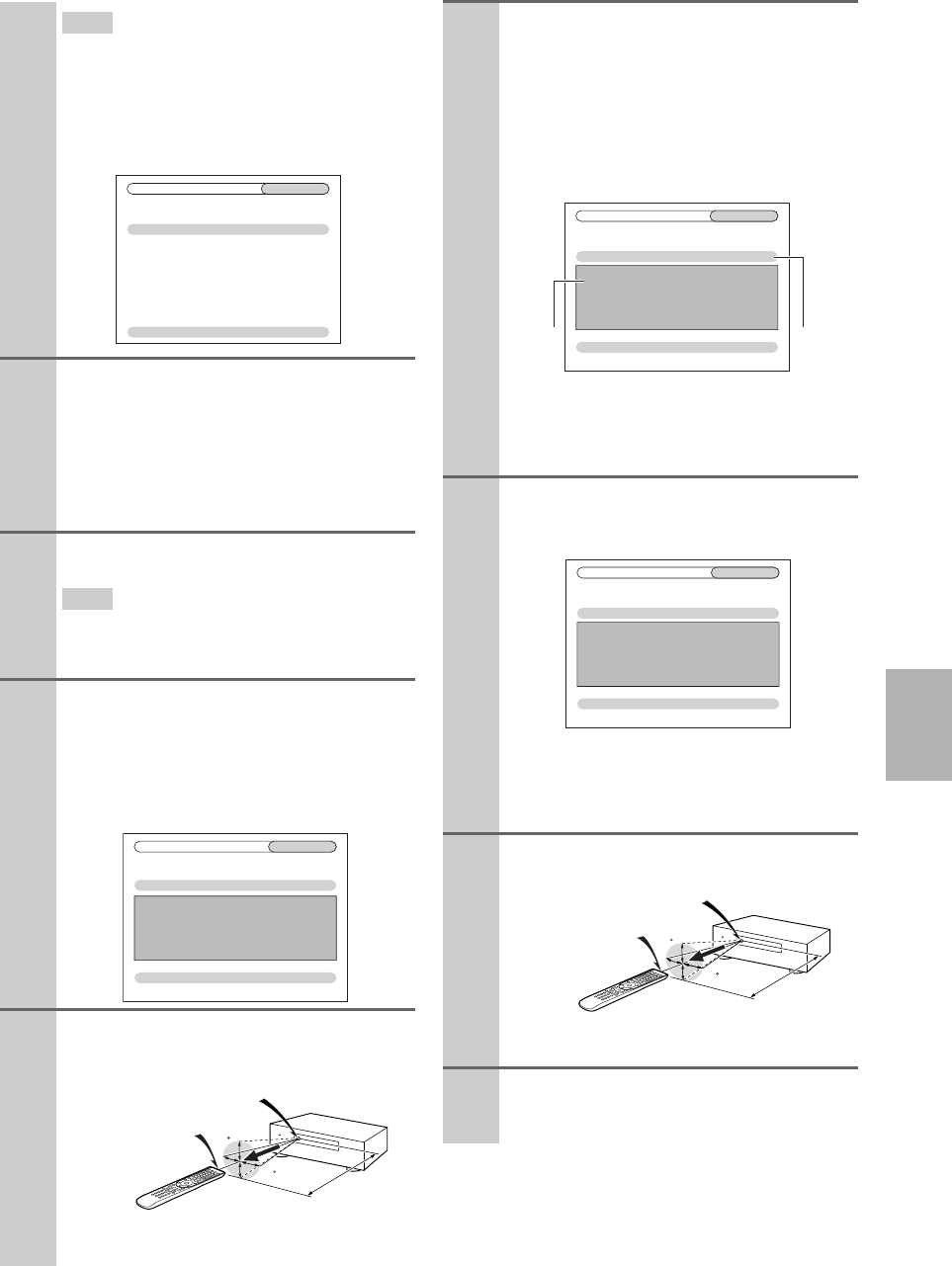
93
En
Tip
• If you cannot access the database, a message “Cannot
connect to database.” will appear. Press Enter to
return to the previous step.
• If the brand name is not found, use r to select “Not
Listed”, and then press Enter.
The following screen appears.
8Use q/w to select “Search by model number
(via network)”, and then press Enter.
The model number input panel appears.
When you do NOT have a network connection
or if you are not sure about the exact model,
select “Skip”, and then press Enter.
If you select “Skip”, you will go to step 11.
9Enter the model in a similar manner as in the
case of the brand name (step 6).
Tip
• After entering the 3rd character, press Enter to start
searching.
• You cannot enter a space character.
10 Use q/w to select the model, and then press
Enter.
If the model is not found, use r to select “Not
Listed”, and then press Enter.
After searching is completed, a message for
remote control code transfer will appear.
11 While pointing the remote controller at the AV
controller’s remote control sensor, press Enter.
8–1. Remote Mode Setup TV
Skip
Search by model number (via network)
Category
Brand
Model
TV
Sonic
(Option)
8–1. Remote Mode Setup TV
OK
Category
Brand
Model
TV
XXXXX
xxxxx
Now we are ready to transfer data to the remote.
Please hold the remote so that it is facing the receiver.
Use ENTER button of your remote to activate “OK”.
Ready?
15
15
Approx.
16ft. (5 m)
Incoming sensor
Remote control sensor (Transmitter)
15° off center
(Left/Right/Up/Down)
12 When you searched for the model, a message
“Successful” will appear. Now the transfer is
successful!
Go to step 15.
When you did NOT search for the model, the
following screen appears.
Push any key (except for arrow buttons and
Enter) to see if the component responds.
*1 When category other than TV have been selected,
the content is different.
*2 Asterisks in [***/***] mean the order of the candi-
date code and the total number of the codes for the
brand.
13 If you can control component, press Receiver,
use q/w to select “Works”, and then press
Enter.
If you cannot control component, press
Receiver, use q/w to select “Doesn’t work
(Retry)” and press Enter.
The next code appears. Repeat from step 11.
14 Press Enter to transfer the determined code.
15 Press Enter.
You’ll return to the category selection menu.
Press Setup to end the remote mode setup.
8–1. Remote Mode Setup TV
Works
Doesn’t work (Retry)
1. Push some key to see if the TV responds.
(except Arrow and Enter.)
2. Choose “Works” or “Doesn’t work”.
Category
Brand
Code
TV
XXXXX
xxxxx[***/***]
*1 *2
8–1. Remote Mode Setup TV
OK
Now we are ready to transfer data to the remote.
Please hold the remote so that it is facing the receiver.
Use ENTER button of your remote to activate “OK”.
Ready?
Category
Brand
Code
TV
XXXXX
xxxxx[***/***]
15
15
Approx.
16ft. (5 m)
Incoming sensor
Remote control sensor (Transmitter)
15° off center
(Left/Right/Up/Down)

94
En
You’ll need to enter a code for each component that you
want to control.
Note
• The remote control codes provided are correct at the time of
printing, but are subject to change.
Integra/Onkyo components that are connected via u are
controlled by pointing the remote controller at the AV con-
troller, not the component. This allows you to control
components that are out of view, in a rack, for example.
If you want to control an Integra/Onkyo component by
pointing the remote controller directly at it, or you want to
control an Integra/Onkyo component that’s not connected
via u, use the following remote control codes:
•BD/DVD
`30627:
Integra/Onkyo DVD player without u
•TV/CD
`71817:
Integra/Onkyo CD player without u
`11807:
TV with p
If you want to control an Integra/Onkyo component by
pointing the remote controller directly at it, use the follow-
ing remote control codes:
`32900:
Integra/Onkyo Blu-ray Disc player
`32901:
Integra/Onkyo HD DVD player
`70868:
Onkyo MD recorder without u
`71323:
Onkyo CD recorder without u
`82990:
Onkyo Dock without u
Entering Remote Control Codes
1Look up the appropriate remote control code in
the separate Remote Control Codes list.
The codes are organized by category (e.g., DVD
player, TV, etc.).
2While holding down Remote Mode to which you
want to enter a code, press and hold down Dis-
play (about 3 seconds).
The Remote Mode button lights.
Note
• Remote control codes cannot be entered for Receiver
and Zone.
• Only TV remote control codes can be entered for TV.
• Except for Receiver, TV and Zone, remote control
codes from any category can be entered as Remote
Mode. However, these buttons also work as input selector
buttons (➔26), so choose a Remote Mode that corre-
sponds with the input to which you connect your compo-
nent. For example, if you connect your CD player to the
CD input, choose TV/CD when entering its remote control
code.
3Within 30 seconds, use the number buttons to
enter the 5-digit remote control code.
Remote Mode button flashes twice.
If the remote control code is not entered success-
fully, Remote Mode button will flash once slowly.
Remote Control Codes for Integra/
Onkyo Components Connected via u
1Make sure the Integra/Onkyo component is con-
nected with an u cable and an analog audio
cable (RCA).
See “Connecting Integra/Onkyo u Components”
for details (➔21).
2Enter the appropriate remote control code for
Remote Mode.
•BD/DVD
`31612:
Integra/Onkyo DVD player with u
•Tape
`42157:
Onkyo cassette tape deck with u
•TV/CD
`71327:
Integra/Onkyo CD player with u
•Port
`81993:
Onkyo Dock with u
See the previous section for how to enter remote
control codes.
3Press Remote Mode, point the remote controller
at the AV controller, and operate the component.

95
En
You can reset a Remote Mode to its default remote con-
trol code.
You can reset the remote controller to its default settings.
By pressing Remote Mode that’s been programmed with
the remote control code for your component, you can con-
trol your component as below.
For details on entering a remote control code for other
components, see “Entering Remote Control Codes”
(➔94).
Controlling a TV
TV is preprogrammed with the remote control code for
controlling a TV that supports the p*1 (limited to
some models). The TV must be able to receive remote
control commands via p and be connected to the
AV controller via HDMI. If controlling your TV via
p doesn’t work very well, program your TV’s
remote control code into TV and use the TV remote mode
to control your TV.
Controlling a Blu-ray Disc/DVD Player, HD
DVD Player or DVD Recorder
BD/DVD is preprogrammed with the remote control code
for controlling a component that supports the p*1
(limited to some models). The component must be able to
receive remote control commands via p and be
connected to the AV controller via HDMI.
*1 The p supported by the AV controller is the CEC
system control function of the HDMI standard.
Resetting Remote Mode Buttons
1While holding down Remote Mode that you want
to reset, press and hold down Home until Remote
Mode button lights (about 3 seconds).
2Within 30 seconds, press Remote Mode again.
Remote Mode button flashes twice, indicating that
the button has been reset.
Each of Remote Mode is preprogrammed with a
remote control code. When a button is reset, its pre-
programmed code is restored.
Note
•The learning command is also reset.
Resetting the Remote Controller
1While holding down Receiver, press and hold
down Home until Receiver lights (about 3 sec-
onds).
2Within 30 seconds, press Receiver again.
Receiver flashes twice, indicating that the remote
controller has been reset.
Controlling Other Components
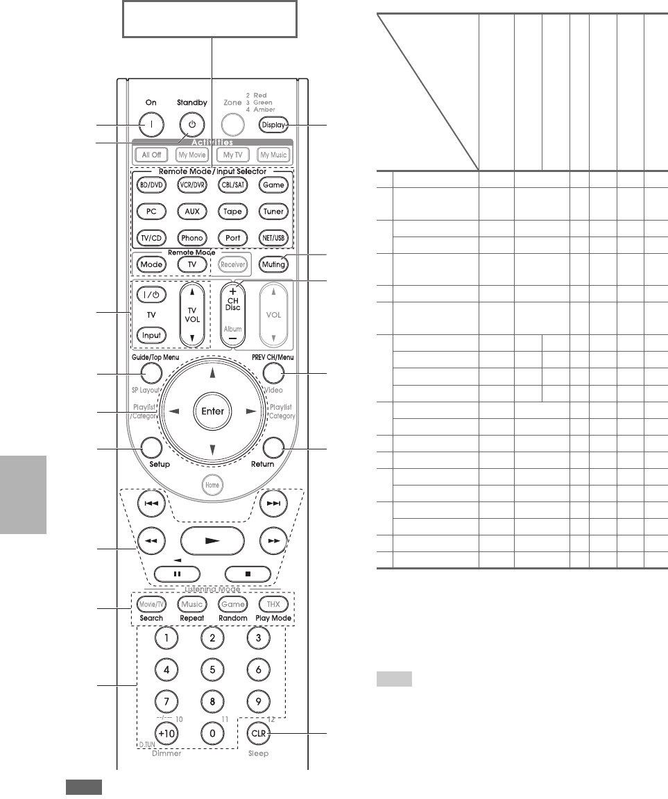
96
En
Note
• With some components, certain buttons may not work as
expected, and some may not work at all.
✔: Available buttons
*1 The p function is not supported. The p sup-
ported by the AV controller is the CEC system control func-
tion of the HDMI standard.
*2 These buttons function as colored buttons or A, B, C, D but-
tons.
*3 3 (Pause) functions as reverse playback.
Tip
• See the “Controlling Your iPod” about the operation of iPod
(➔90).
c
d
a
a
b
i
e
f
h
g
j
k
n
m
l
Press the appropriate Remote
Mode first.
TV
DVD player/DVD recorder
Blu-ray Disc player
HD DVD player
VCR/PVR
Satellite receiver
Cable receiver
CD player/CD recorder
MD recorder
Cassette tape deck
aOn, Standby ✔ ✔ ✔✔✔✔
b9, Input,
TV VOL q/w
✔
cGuide ✔✔✔
Top Menu ✔
dq/w/e/r
Enter
✔✔ ✔✔✔
eSetup ✔✔ ✔✔✔
f1, 3, 2, 5,
4, 7, 6
✔*1 ✔✔✔✔
✔*3
gSearch ✔*1*2 ✔*1 ✔*2 ✔*2 ✔
Repeat ✔*1*2 ✔✔*2 ✔*2 ✔
Random ✔*1*2 ✔*1 ✔*2 ✔*2 ✔
Play Mode ✔*1*2 ✔*1 ✔*2 ✔*2 ✔
hNumber: 1 to 9, 0✔✔ ✔✔✔
Number: +10 ✔*1 ✔*1 ✔✔ ✔
iDisplay ✔✔ ✔✔✔
jMuting ✔ ✔ ✔✔✔✔
kCH +/– ✔✔ ✔✔
Disc +/– ✔✔
lPREV CH ✔✔✔
Menu ✔
mReturn ✔✔ ✔✔
nCLR ✔✔ ✔✔✔
Components
Buttons
97
En
Via onscreen menu, you can specify what actions will be
taken by the Easy macro command in the Easy macro
mode (➔28).
Here are the default settings.
Activities Setup
1Press Receiver followed by Setup.
The main menu appears onscreen.
Tip
• If the main menu doesn’t appear, make sure the appropri-
ate external input is selected on your TV.
2Use q/w to select “Remote Controller Setup”, and
then press Enter.
The “Remote Controller Setup” menu appears.
3Use q/w to select “Activities Setup”, and then
press Enter.
The “Activities Setup” menu appears.
4Use q/w to select “My Movie”, “My TV”, or “My
Music”, and then press Enter.
■My Movie:
Actions for My Movie is changed.
■My TV:
Actions for My TV is changed.
■My Music:
Actions for My Music is changed.
5Use q/w to select an item, and use e/r to change
the settings.
The items are explained below.
■Source
`BD/DVD, VCR/DVR, CBL/SAT, GAME, PC,
AUX, TAPE, TUNER, TV/CD, PHONO,
PORT, NET/USB
With this setting, you can choose the input source.
■TV Power On
`Enable:
TV will turn on.
`Disable:
TV will not turn on.
This option enables the TV to turn on when
Activities is pressed.
1. Remote Mode Setup
2. Activities Setup
8. Remote Controller Setup
My Movie
My TV
My Music
8–2. Activities Setup
8–2. Activities Setup My Movie
Source
TV Power On
Source Power On
Receiver Power On
Receiver Source Change
Source Play
BD/DVD
Enable
Enable
Enable
Enable
Enable
■Source Power On
`Enable:
Source component will turn on.
`Disable:
Source component will not turn on.
This option enables the source component to turn
on when Activities is pressed.
■Receiver Power On
`Enable:
The AV controller will turn on.
`Disable:
The AV controller will not turn on.
This option enables the AV controller to turn on
when Activities is pressed.
■Receiver Source Change
`Enable:
The AV controller will change input source.
`Disable:
The AV controller will not change input
source.
This option enables the AV controller input selec-
tor to change when Activities is pressed.
■Source Play
`Enable:
The source component will start playback.
`Disable:
The source component will not start playback.
This option enables the source component to start
playback when Activities is pressed.
Item Default Settings
My Movie My TV My Music
Source BD/DVD CBL/SAT TV/CD
TV Power On Enable Enable Disable
Source Power On Enable Enable Enable
Receiver Power On Enable Enable Enable
Receiver Source
Change
Enable Enable Enable
Source Play Enable Disable Enable
98
En
The AV controller’s remote controller can learn the com-
mands of other remote controllers. By transmitting, for
example, the Play command from your CD player’s
remote controller, the remote controller can learn it, and
then transmit the exact same command when its 1 is
pressed in the CD remote mode.
This is useful when you’ve entered the appropriate remote
control code (➔94) but some buttons don’t work as
expected.
6Press Enter.
A message for transfer will appear.
To use the remote controller, point it at the AV con-
troller’s remote control sensor, as shown below.
7Press Enter.
When the transfer is successful, the following screen
appears.
8Press Enter.
The “Activities Setup” menu appears onscreen.
9Press Setup.
The setup menu closes.
8–2. Activities Setup My Movie
OK
Now we are ready to transfer data to the remote.
Please hold the remote so that it is facing the receiver.
Use ENTER button of your remote to activate “OK”.
Ready?
15
15
Approx.
16ft. (5 m)
Incoming sensor
Remote control sensor (Transmitter)
15° off center
(Left/Right/Up/Down)
8–2. Activities Setup My Movie
Wait...
8–2. Activities Setup My Movie
Return
Successful
Learning Commands
1While holding down Remote Mode for the mode
in which you want to use the command, press and
hold down On until Remote Mode button lights
(about 3 seconds).
2On the supplied remote controller, press the but-
ton you want to learn the new command.
Note
• The following buttons cannot learn new commands:
Remote Mode, All Off, My Movie, My TV,
My Music and Mode.
3Point the remote controllers at each other, within
about 4 inches (10 cm) apart, and then press and
hold the button whose command you want to learn
until Remote Mode button flashes.
If the command is learned successfully, Remote
Mode button flashes twice.
4To learn more commands, repeat steps 2 and 3.
Press any Remote Mode when you’ve finished.
Remote Mode button flashes twice.
On
Remote
Mode
POWER SLEEP DIMMER SUR
MODE
VIDEO-1 VIDEO-2
TAP E
DVD C D
C D DVD
TUNER
TUNER
PHONO
INPUT SELECTOR
DISC
TAP E
VOLUME
EVEL
CH SEL
PRESET
MUTING
TEST
TONE
MULTI-CH
INPUT
GROUP
R
Within about 4
inches (10 cm)
Supplied remote
controller
99
En
Note
• The remote controller can learn approximately 70 to 90 com-
mands, although this will be less if commands that use a lot of
memory are learned.
• Remote controller buttons such as Play, Stop, Pause, and so on
are preprogrammed with commands for controlling
Integra/Onkyo CD players, cassette decks, and DVD players.
However, they can learn new commands, and you can restore the
preprogrammed commands at any time by resetting the remote
controller (➔95).
• To overwrite a previously learned command, repeat this proce-
dure.
• Depending on the remote controller that you are using, there may
be some buttons that won’t work as expected, or even some
remotes that cannot be learned at all.
• Only commands from infrared remote controllers can be learned.
• When the remote controller’s batteries expire, all learned com-
mands will be lost and will have to be learned all over again, so
don’t discard your other remote controllers.
■Deleting Learning Commands
1. While holding down Remote Mode for the mode in
which you want to delete the command, press and hold
down TV 9 until Remote Mode button lights
(about 3 seconds).
2. Press Remote Mode or the button from which you
want to delete the commands.
Remote Mode button flashes twice.
When you press Remote Mode, all commands
learned in that remote mode will be deleted.
You can program the remote controller’s Activities to
perform a sequence of remote control actions.
Example:
To play a CD you typically need to perform the following
actions:
1. Press Receiver to select the Receiver remote control-
ler mode.
2. Press On to turn on the AV controller.
3. Press TV/CD to select the TV/CD input source.
4. Press 1 to start playback on the CD player.
You can program Activities so that all four actions are
performed with just one button press.
Making Macros
Each Activities can store one macro, and each macro can
contain up to 32 commands.
Running Macros
Deleting Macros
Using Normal Macros
Receiver
My Movie,
My TV,
My Music
All Off
1While holding down Receiver, press and hold
down My Movie, My TV, or My Music until
My Movie, My TV, or My Music lights (about 3
seconds).
2Press the buttons whose actions you want to pro-
gram into the macro in the order you want them
performed.
For the CD example above, you’d press the following
buttons: On, TV/CD, 1.
Note
•Mode is invalid at macro making operation.
3When you’ve finished, press Activities again.
Activities button flashes twice.
If you enter 32 commands, the process will finish
automatically.
Note
• Once you have taught new macro commands, the original
macro will no longer work. If you retrieve it, you will have
to taught again.
Press My Movie, My TV, or My Music.
The commands in the macro are transmitted in the
order in which they were programmed. Keep the
remote controller pointed at the AV controller until
all of the commands have been transmitted.
Macros can be run at any time, regardless of the cur-
rent remote controller mode.
1While holding down Home, press and hold down
All Off until All Off lights (about 3 seconds).
2Press All Off again.
All Off flashes twice.
Note
• You can use Easy macro when the macro is deleted
(➔28).
• When you use Normal macro, you cannot use the easy
macro command including the change of the source com-
ponent.
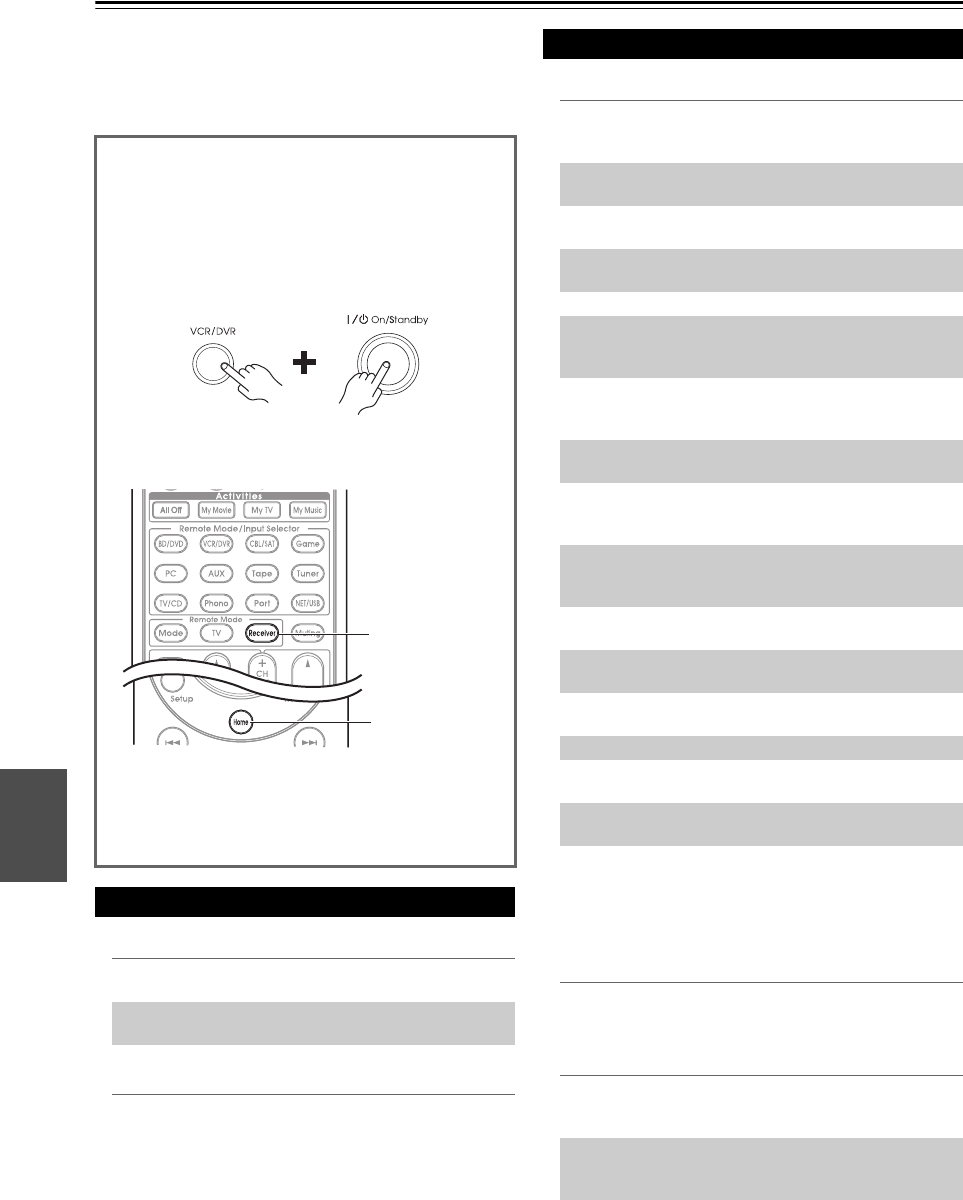
100
En
Others
Troubleshooting
If you have any trouble using the AV controller, look for a
solution in this section. If you can’t resolve the issue your-
self, contact the dealer from whom you purchased this
unit.
■Can’t turn on the AV controller
■The Standby indicator flashes red
■There’s no sound, or it’s very quiet
■Audio Return Channel audio can be heard via
the TV/monitor speakers connected to the HDMI
OUT SUB jack
■Only the front speakers produce sound
If you can’t resolve the issue yourself, try resetting the
AV controller before contacting the dealer from whom
you purchased this unit.
To reset the AV controller to its factory defaults, turn
it on and, while holding down VCR/DVR, press
On/Standby. “Clear” will appear on the display and
the AV controller will enter Standby mode.
Note that resetting the AV controller will delete your
radio presets and custom settings.
To reset the remote controller to its factory defaults,
while holding down Receiver, press and hold down
Home until Receiver button lights (about 3 seconds).
Within 30 seconds, press Receiver again.
Power
Make sure that the power cord is properly plugged
into the wall outlet.
—
Unplug the power cord from the wall outlet, wait five
seconds or more, then plug it in again.
—
The protection circuit has been activated. Remove
the power cord from the wall outlet immediately.
Disconnect all speaker cables and input sources, and
leave the AV controller with its power cord discon-
nected for 1 hour. After that, reconnect the power
cord and set the volume to maximum. If the AV con-
troller stays on, set the volume to minimum, discon-
nect the power cord, and reconnect your speakers
and input sources. If the AV controller turns off
when you set the volume to maximum, disconnect
the power cord, and contact the dealer from whom
you purchased this unit.
—
Home
Receiver
Audio
Make sure that your multichannel power amplifier is
turned on and set up correctly and connected to the
AV controller properly.
12
Make sure that the digital input source is selected
properly.
53
Make sure that all audio connecting plugs are pushed
in all the way.
18
Make sure that the inputs and outputs of all compo-
nents are connected properly.
19-21
Make sure that the input source is properly selected. 26
Check the volume. The AV controller is designed for
home theater enjoyment. It has a wide volume range,
allowing precise adjustment.
—
If the MUTING indicator is flashing on the display,
press the remote controller’s Muting to unmute the
AV controller.
27
While a pair of headphones is connected to the
Phones jack, no sound is output by the speakers.
28
If there’s no sound from a DVD player connected to
an HDMI IN, check the DVD player’s output set-
tings, and be sure to select a supported audio format.
—
Check the digital audio output setting on the con-
nected device. On some game consoles, such as
those that support DVD, the default setting is off.
—
With some DVD-Video discs, you need to select an
audio output format from a menu.
—
If your turntable uses an MC cartridge, you must
connect an MC head amp, or an MC transformer.
—
Make sure that none of the connecting cables are
bent, twisted, or damaged.
—
Not all listening modes use all speakers. 43
Specify the speaker distances and adjust the individ-
ual speaker levels.
55
Make sure that the speaker setup microphone is not
still connected.
—
The input signal format is set to “PCM” or “DTS”.
Set it to “Auto”.
70
Change the “Audio Selector” settings of the TV/CD
input selector.
70
When the Stereo or Mono listening mode is selected,
only the front speakers and subwoofer produce
sound.
—
In the Mono listening mode, only the front speakers
output sound if the “Output Speaker” setting is set
to “Left / Right”.
57
Check the Speaker Configuration. 54

101
En
■Only the center speaker produces sound
■The surround speakers produce no sound
■The center speaker produces no sound
■The front high, front wide and surround back
speakers produce no sound
■The subwoofer produces no sound
■There’s no sound with a certain signal format
■Can’t get 6.2/7.2 playback
■The speaker volume cannot be set as required
(The volume cannot be set to Max(100.0))
■Noise can be heard
■The Late Night function doesn’t work
■The analog multichannel input doesn’t work
■About DTS signals
■The beginning of audio received by an HDMI IN
can’t be heard
If you use the Dolby Pro Logic IIx Movie, Dolby Pro
Logic IIx Music, or Dolby Pro Logic IIx Game lis-
tening mode with a mono source, such as an AM
radio station or mono TV program, the sound is con-
centrated in the center speaker.
—
In the Mono listening mode, only the front speakers
output sound if the “Output Speaker” setting is set
to “Center”.
57
Make sure the speakers are configured correctly. 54
When the T-D (Theater-Dimensional), Stereo or
Mono listening mode is selected, the surround
speakers produce no sound.
—
Depending on the source and current listening mode,
not much sound may be produced by the surround
speakers. Try selecting another listening mode.
—
Make sure the speakers are configured correctly. 54
When the Stereo or Mono listening mode is selected,
the center speaker produces no sound.
—
In the Mono listening mode, only the front speakers
output sound if the “Output Speaker” setting is set
to “Left / Right”.
57
Make sure the speakers are configured correctly. 54
Depending on the current listening mode, no sound
may be produced by the front high, front wide and
surround back speakers. Select another listening
mode.
43
Not much sound may be produced by the front high,
front wide and surround back speakers with some
sources.
—
Make sure the speakers are configured correctly. 54
When you play source material that contains no
information in the LFE channel, the subwoofer pro-
duces no sound.
—
Make sure the speakers are configured correctly. 54
Check the digital audio output setting on the con-
nected device. On some game consoles, such as
those that support DVD, the default setting is off.
—
With some DVD-Video discs, you need to select an
audio output format from a menu.
—
Depending on the input signal, some listening modes
cannot be selected.
43–48
If no surround back speakers, front wide and front
high speakers are connected, or the Zone 2/3 speak-
ers are being used, 6.2/7.2 playback is not possible.
—
You can not always select all of the listening modes,
depending on the number of the speakers connected.
43–48
Check to see if a maximum volume has been set. 64
If the volume level of each individual speaker has
been adjusted to high positive values, then the maxi-
mum master volume possible may be reduced. Note
that the individual speaker volume levels are set
automatically after Audyssey MultEQ®XT32 Room
Correction and Speaker Setup function has been
completed.
29, 55
Using cable ties to bundle audio cables with power
cords, speaker cables, and so on may degrade the
audio performance, so don’t do it.
—
An audio cable may be picking up interference. Try
repositioning your cables.
—
Make sure the source material is Dolby Digital,
Dolby Digital Plus, and Dolby TrueHD.
69
Check the multichannel input connections. —
Make sure that the multichannel input is assigned to
the input selector.
53
Make sure that the multichannel input is selected. 70
Check the audio output settings on your source com-
ponent.
—
When DTS program material ends and the DTS bit-
stream stops, the AV controller remains in DTS lis-
tening mode and the DTS indicator remains on. This
is to prevent noise when you use the pause, fast for-
ward, or fast reverse function on your player. If you
switch your player from DTS to PCM, because the
AV controller does not switch formats immediately,
you may not hear any sound, in which case you
should stop your player for about three seconds, and
then resume playback.
—
With some CD and LD players, you won’t be able to
playback DTS material properly even though your
player is connected to a digital input on the AV con-
troller. This is usually because the DTS bitstream
has been processed (e.g., output level, sampling rate,
or frequency response changed) and the AV control-
ler doesn’t recognize it as a genuine DTS signal. In
such cases, you may hear noise.
—
When playing DTS program material, using the
pause, fast forward, or fast reverse function on your
player may produce a short audible noise. This is not
a malfunction.
—
Since it takes longer to identify the format of an
HDMI signal than it does for other digital audio sig-
nals, audio output may not start immediately.
—

102
En
■There’s no picture
■There’s no picture from a source connected to
an HDMI IN
■The on-screen menus don’t appear
■The picture is distorted
■The on screen display does not appear
■Reception is noisy, FM stereo reception is
noisy, or the FM STEREO indicator doesn’t light
■The remote controller doesn’t work
■Can’t control other components
Video
Make sure that all video connecting plugs are pushed
in all the way.
18
Make sure that each video component is properly
connected.
19, 20,
88
If your TV is connected to the HDMI output, set the
“Monitor Out” setting other than “Analog”, and
select “-----” in the “HDMI Input” to watch com-
posite video, S-Video, and component video sources.
50, 51
If your TV is connected to the COMPONENT
VIDEO MONITOR OUT, MONITOR OUT S, or
MONITOR OUT V, set the “Monitor Out” setting
to “Analog”, and select “-----” in the “Compo-
nent Video Input” to watch composite video and
S-Video sources.
50, 52
If the video source is connected to a component
video input, you must assign that input to an input
selector, and your TV must be connected to either
the HDMI output or COMPONENT VIDEO MON-
ITOR OUT.
20, 52
If the video source is connected to a composite video
input, your TV must be connected to the HDMI out-
put or the corresponding composite video output.
20
If the video source is connected to an HDMI input,
you must assign that input to an input selector, and
your TV must be connected to the HDMI output.
19, 51
On your TV, make sure that the video input to which
the AV controller is connected is selected.
—
If you selected “Both(Main)” or “Both(Sub)” in the
“Monitor Out” setting, no picture may appear on
your TV that is connected to a secondary HDMI out-
put (not a priority HDMI output). In this case,
change the setting to “Both”.
—
Reliable operation with an HDMI-to-DVI adapter is
not guaranteed. In addition, video signals from a PC
are not guaranteed.
106
When the “Monitor Out” setting is set to “Analog”,
and the “Resolution” setting is set to anything other
than “Through”, no video is output by the HDMI
outputs.
50, 51
When the “Resolution” is set to any resolution not
supported by the TV, no video is output by the
HDMI outputs.
51
If the message “Resolution Error” appears on the
AV controller’s display, this indicates that your TV
does not support the current video resolution and
you need to select another resolution on your DVD
player.
—
(Australian models) Specify the TV system used in
your area in the “TV Format”.
65
On your TV, make sure that the video input to which
the AV controller is connected is selected.
—
If your TV is connected to the analog outputs, set the
“Monitor Out” setting to “Analog”.
50
(Australian models) Specify the TV system used in
your area in the “TV Format”.
65
If you select other than “Analog” in the “Monitor
Out” setting, the immediate display will not appear
when the input signal from the COMPONENT
VIDEO IN is output to a device connected to the
COMPONENT VIDEO MONITOR OUT.
50
Depending on the input signal, the on screen display
may not appear when the input signal from the
HDMI IN is output to a device connected to the
HDMI output.
65
Tuner
Relocate your antenna. —
Move the AV controller away from your TV or com-
puter.
—
Listen to the station in mono. 32
When listening to an AM station, operating the
remote controller may cause noise.
—
Passing cars and airplanes can cause interference. —
Concrete walls weaken radio signals. —
If nothing improves the reception, install an outdoor
antenna.
—
Remote Controller
Before operating this unit, be sure to press
Receiver.
—
Make sure that the batteries are installed with the
correct polarity.
4
Install new batteries. Don’t mix different types of
batteries, or old and new batteries.
4
Make sure that the remote controller is not too far
away from the AV controller, and that there’s no
obstruction between the remote controller and the
AV controller’s remote control sensor.
4
Make sure that the AV controller is not subjected to
direct sunshine or inverter-type fluorescent lights.
Relocate if necessary.
—
If the AV controller is installed in a rack or cabinet
with colored-glass doors, the remote controller may
not work reliably when the doors are closed.
—
Make sure you’ve selected the correct remote con-
troller mode.
11, 95
When using the remote controller to control other
manufacturers’ AV components, some buttons may
not work as expected.
—
Make sure you’ve entered the correct remote control
code.
94
Make sure to set the same ID on both the AV control-
ler and remote controller.
65
If it’s an Integra/Onkyo component, make sure that
the u cable and analog audio cable are connected
properly. Connecting only an u cable won’t work.
21
Make sure you’ve selected the correct remote con-
troller mode.
11, 95

103
En
■Can’t learn commands from another remote
controller
■Can’t record
■There’s no sound
■Can’t access the server or Internet radio
■Playback stops while listening to music files on
the server
■Can’t connect to the AV controller from a Web
browser
■Can’t access the music files on a USB device
■Stand-by power consumption
■The sound changes when I connect my
headphones
■The speaker distance cannot be set as required
■How do I change the language of a multiplex
source
If you’ve connected an u-capable Integra/Onkyo
MD recorder, CD recorder, RI Dock to the TAPE
IN/OUT jacks, or an RI Dock to the GAME IN or
VCR/DVR IN jacks, for the remote controller to
work properly, you must set the input display.
28
If you cannot operate it, you will need to enter the
appropriate remote control code.
92
To control another manufacturer’s component, point
the remote controller at that component.
94
If none of the codes work, use the Learning function
to learn the commands of the other component’s
remote controller.
98
To control an Integra/Onkyo component that’s con-
nected via u, point the remote controller at the AV
controller. Be sure to enter the appropriate remote
control code first.
94
To control an Integra/Onkyo component that’s not
connected via u, point the remote controller at the
component. Be sure to enter the appropriate remote
control code first.
94
The entered remote control code may not be correct.
If more than one code is listed, try each one.
—
When learning commands, make sure that the trans-
mitting ends of both remote controllers are pointing
at each other.
—
Are you trying to learn from a remote controller that
cannot be used for learning? Some commands can-
not be learned, especially those that contain several
instructions.
—
Recording
On your recorder, make sure the correct input is
selected.
—
To prevent signal loops and damage to the AV con-
troller, input signals are not fed through to outputs
with the same name (VCR/DVR IN to VCR/DVR
OUT).
—
Zone 2/3
Only components connected to analog inputs can be
played in Zone 2/3.
—
Music Server and Internet Radio
Check the network connection between the AV con-
troller and your router or switch.
—
Make sure that your modem and router are properly
connected, and make sure they are both turned on.
—
Make sure the server is up and running and compati-
ble with the AV controller.
76
Check the “Network Settings”. 77
Make sure your server is compatible with the AV
controller.
76
If you download or copy large files on your com-
puter, playback may be interrupted. Try closing any
unused programs, use a more powerful computer, or
use a dedicated server.
—
If the server is serving large music files to several
networked devices simultaneously, the network may
become overloaded and playback may be inter-
rupted. Reduce the number of playback devices on
the network, upgrade your network, or use a switch
instead of a hub.
—
If you’re using DHCP, your router may not always
allocate the same IP address to the AV controller, so
if you find that you can’t connect to a server or Inter-
net radio station, recheck the AV controller’s IP
address on “Network” screen.
78
Check the “Network Settings”. 77
USB Mass Storage Device Playback
Make sure the USB device is plugged in properly. —
The AV controller supports USB devices that sup-
port the USB mass storage device class. However,
playback may not be possible with some USB
devices even if they conform to the USB mass stor-
age device class.
—
USB memory devices with security functions cannot
be played.
—
Others
In the following cases, the power consumption may
reach up to a maximum of 30W:
1. You are using the Universal Port jack.
2. “Control” is set to “Enable” in the “Network”
setting.
3. “HDMI Control(RIHD)” setting is set to
“On”. (Depending on the TV status, the AV
controller will enter Standby mode as usual.)
66, 77,
89
When a pair of headphones is connected, the listen-
ing mode is set to Stereo, unless it’s already set to
Stereo, Mono or Direct.
—
In some cases, corrected values suitable for home
theater use may be set automatically.
—
Use the “Multiplex” setting on the “Audio Adjust”
menu to select “Main” or “Sub”.
57

104
En
■The u functions don’t work
■The functions System On/Auto Power On and
Direct Change don’t work for components
connected via u
■When performing “Audyssey MultEQ®XT32
Room Correction and Speaker Setup”, the
measurement fails showing the message
“Ambient noise is too high.”.
■The following settings can be made for the
S-Video and composite video inputs
You must use the buttons on the unit to make these set-
tings.
1. While holding down the input selector button for the input
source that you want to set, press Setup.
2. Use e/r to change the setting.
3. Press the input selector button for the input source that you
want to set when you’ve finished.
• Video Attenuation
This setting can be made for the BD/DVD, VCR/DVR,
CBL/SAT, Game, or AUX input.
If you have a games console connected to the composite
video input, and the picture isn’t very clear, you can
attenuate the gain.
Video ATT:OFF: (default).
Video ATT:ON: Gain reduced by 2dB.
The AV controller can upconvert component video,
S-Video, and composite video sources for display on a TV
connected to the HDMI output. However, if the picture
quality of the source is poor, upconversion may make the
picture worse or disappear altogether.
In this case, try the following:
Note
•If “Monitor Out” setting is set to “Analog”, press VCR/DVR
and Return on the AV controller at the same time. Select “Skip”
in the “VideoProcessor” setting on the display. To reset back to
the original setting, press the same button at the same time. If
you select “Use”, the AV controller will output video signals
from the video processor.
To use u, you must make an u connection and an
analog audio connection (RCA) between the compo-
nent and AV controller, even if they are connected
digitally.
21
While Zone 2 or Zone 3 is selected, the u func-
tions don’t work.
—
These functions don’t work when Zone 2/3 is turned
on.
—
This can be caused by any malfunction in your
speaker unit. Check if the unit produces normal
sounds.
—
The AV controller contains a microcomputer for signal
processing and control functions. In very rare situations,
severe interference, noise from an external source, or
static electricity may cause it to lockup. In the unlikely
event that this happens, unplug the power cord from the
wall outlet, wait at least five seconds, and then plug it
back in again.
Onkyo is not responsible for damages (such as CD
rental fees) due to unsuccessful recordings caused by
the unit’s malfunction. Before you record important
data, make sure that the material will be recorded cor-
rectly.
Before disconnecting the power cord from the wall out-
let, set the AV controller to Standby.
Important Note Regarding Video Playback
1If the video source is connected to a component
video input, connect your TV to the COMPO-
NENT VIDEO MONITOR OUT.
If the video source is connected to an S-Video input,
connect your TV to a MONITOR OUT S.
If the video source is connected to a composite video
input, connect your TV to MONITOR OUT V.
2On the main menu, select “Input/Output Assign”,
and then select “HDMI Input”.
Select the relevant input selector, and assign it to
“-----” (➔51).
3On the main menu, select “Input/Output Assign”,
and then select “Component Video Input” (➔52):
If the video source is connected to COMPO-
NENT VIDEO IN 1, select the relevant input
selector, and assign it to “IN 1”.
If the video source is connected to COMPO-
NENT VIDEO IN 2, select the relevant input
selector, and assign it to “IN 2”.
If the video source is connected to COMPO-
NENT VIDEO IN 3, select the relevant input
selector, and assign it to “IN 3”.
If the video source is connected to an S-Video
input or composite video input, select the relevant
input selector, and assign it to “-----”.

105
En
Specifications
Amplifier Section
Video Section
Tuner Section
General
■HDMI
■Video Inputs
■Video Outputs
■Audio Inputs
■Audio Outputs
■Others
Specifications and features are subject to change
without notice.
Input Sensitivity and Impedance
200 mV/47 kΩ (LINE)
2.5 mV/47 kΩ (PHONO MM)
Rated RCA Output Level and Impedance
1 V/470 Ω (PRE OUT)
Maximum RCA Output Level and Impedance
5.5 V/470 Ω (PRE OUT)
Rated XLR Output Level and Impedance
2 V/ 470 Ω (PRE OUT)
Maximum XLR Output Level and Impedance
11.0 V/ 470 Ω (PRE OUT)
Phono Overload 70 mV (MM 1 kHz 0.5%)
Frequency Response 5 Hz - 100 kHz/+1 dB, -3 dB (Direct mode)
Tone Control Characteristics
±10 dB, 50 Hz (BASS)
±10 dB, 20 kHz (TREBLE)
Signal to Noise Ratio 110 dB (LINE, IHF-A)
80 dB (PHONO, IHF-A)
Input Sensitivity/Output Level and Impedance
1 Vp-p/75 Ω (Component and S-Video Y)
0.7 Vp-p/75 Ω (Component PB/CB, PR/CR)
0.28 Vp-p/75 Ω (S-Video C)
1 Vp-p/75 Ω (Composite)
Component Video Frequency Response
5 Hz - 100 MHz/+0 dB, -3 dB
FM Tuning Frequency Range
(North American)
87.5 MHz - 107.9 MHz
(Australian)
87.5 MHz - 108.0 MHz, RDS
AM Tuning Frequency Range
522/530 kHz - 1611/1710 kHz
Preset Channel 40
Digital Tuner (North American)
SIRIUS
Power Supply (North American)
AC 120 V, 60 Hz
(Australian)
AC 220 - 240 V, 50/60 Hz
Power Consumption (North American) 1.2 A
(Australian) 110 W
Stand-by Power Consumption
(North American) 0.2 W
(Australian) 0.3 W
Dimensions (W × H × D)
435 mm × 198.5 mm × 445 mm
17-1/8" × 7-13/16" × 17-1/2"
Weight 13.5 kg (29.8 lbs.)
Input IN 1, IN 2, IN 3, IN 4, IN 5, IN 6, IN 7,
AUX INPUT
Output OUT MAIN, OUT SUB
Video Resolution 1080p
Audio Format Dolby TrueHD, DTS Master Audio,
DVD-Audio, DSD
Supported 3D, Audio Return Channel, Deep Color,
x.v.Color, LipSync, CEC
Component IN 1, IN 2, IN 3
S-Video BD/DVD, VCR/DVR, CBL/SAT, GAME
Composite BD/DVD, VCR/DVR, CBL/SAT, GAME,
AUX
Analog RGB input PC IN
Component MONITOR OUT, ZONE 2 OUT
S-Video MONITOR OUT, VCR/DVR OUT
Composite MONITOR OUT, VCR/DVR OUT,
ZONE 2 OUT
Digital Optical: 3 (Rear), 1 (Front)
Coaxial: 3
Analog BD/DVD, MULTI CH, VCR/DVR,
CBL/SAT, GAME, PC, TAPE, TV/CD,
AUX, PHONO
Multichannel Inputs 7.1
Balance Inputs 2
Analog VCR/DVR, TAPE, ZONE 2 PRE OUT,
ZONE 3 PRE OUT
Balance Pre Outputs FL, FR, C, SL, SR, SBL, SBR,
LH/LW, RH/RW, SW1, SW2
Analog Multichannel Pre Outputs
9
Subwoofer Pre Outputs 2
Phones 1 (6.3 ø)
SETUP MIC 1
RS232 1
Ethernet 1
IR Input 2
IR Output 1
12 V Trigger Out 3
USB 2 (Front and Rear)
Universal Port 1
RI 1

106
En
About HDMI
Designed to meet the increased demands of digital TV, HDMI (High Definition Multimedia Interface) is a new digital
interface standard for connecting TVs, projectors, Blu-ray Disc/DVD players, set-top boxes, and other video compo-
nents. Until now, several separate video and audio cables have been required to connect AV components. With HDMI, a
single cable can carry control signals, digital video, and up to eight channels of digital audio (2-channel PCM, multichan-
nel digital audio, and multichannel PCM).
The HDMI video stream (i.e., video signal) is compatible with DVI (Digital Visual Interface)*1, so TVs and displays with
a DVI input can be connected by using an HDMI-to-DVI adapter cable. (This may not work with some TVs and displays,
resulting in no picture.)
The AV controller uses HDCP (High-bandwidth Digital Content Protection)*2, so only HDCP-compatible components
can display the picture.
Supported Audio Formats
• 2-channel linear PCM (32–192 kHz, 16/20/24 bit)
• Multichannel linear PCM (up to 7.1 ch, 32–192 kHz, 16/20/24 bit)
• Bitstream (DSD, Dolby Digital, Dolby Digital Plus, Dolby TrueHD, DTS, DTS-HD High Resolution Audio, DTS-HD
Master Audio)
Your Blu-ray Disc/DVD player must also support HDMI output of the above audio formats.
About Copyright Protection
The AV controller supports HDCP (High-bandwidth Digital Content Protection)*2, a copy-protection system for digital
video signals. Other devices connected to the AV controller via HDMI must also support HDCP.
*1 DVI (Digital Visual Interface): The digital display interface standard set by the DDWG*3 in 1999.
*2 HDCP (High-bandwidth Digital Content Protection): The video encryption technology developed by Intel for HDMI/DVI. It’s
designed to protect video content and requires a HDCP-compatible device to display the encrypted video.
*3 DDWG (Digital Display Working Group): Lead by Intel, Compaq, Fujitsu, Hewlett Packard, IBM, NEC, and Silicon Image, this
open industry group’s objective is to address the industry’s requirements for a digital connectivity specification for high-performance
PCs and digital displays.
Note
• The HDMI video stream is compatible with DVI (Digital Visual Interface), so TVs and displays with a DVI input can be connected by
using an HDMI-to-DVI adapter cable. (Note that DVI connections only carry video, so you’ll need to make a separate connection for
audio.) However, reliable operation with such an adapter is not guaranteed. In addition, video signals from a PC are not supported.
• The HDMI audio signal (sampling rate, bit length, etc.) may be restricted by the connected source component. If the picture is poor or
there’s no sound from a component connected via HDMI, check its setup. Refer to the connected component’s instruction manual for
details.
The AV controller’s HDMI interface is based on the following:
Audio Return Channel, 3D, x.v.Color, Deep Color, Lip Sync, DTS-HD Master Audio, DTS-HD High Resolution
Audio, Dolby TrueHD, Dolby Digital Plus, DSD and Multichannel PCM

107
En
Using an RIHD-compatible TV, Player, or Recorder
p, which stands for Remote Interactive over HDMI, is the name of the system control function found on
Integra/Onkyo components. The AV controller can be used with CEC (Consumer Electronics Control), which allows sys-
tem control over HDMI and is part of the HDMI standard. CEC provides interoperability between various components,
however, operation with components other than p-compatible components cannot be guaranteed.
■About p-compatible components
The following components are p-compatible. (As
of February 2010) See the Onkyo web site for latest infor-
mation.
TV
• Panasonic VIERA Link compatible TV
• Toshiba REGZA-LINK compatible TV
• Sharp TV (See Onkyo web site for latest information on
compatible models.)
Players/Recorders
• Onkyo and Integra p-compatible players
• Panasonic VIERA Link compatible players and record-
ers (only when used together with Panasonic VIERA
Link compatible TV)
• Toshiba REGZA-LINK compatible players and record-
ers (only when used together with Toshiba
REGZA-LINK compatible TV)
• Sharp players and recorders (only when used together
with Sharp TV)
*Models other than those mentioned above may have some
interoperability if compatible with CEC which is part of the
HDMI Standard, but operation cannot be guaranteed.
Note
• Do not connect the p-compatible component more than
the following number to the HDMI input terminal so that the
linked operations work properly.
–Blu-ray Disc/DVD player is up to three.
–Blu-ray Disc recorder/DVD recorder/Digital Video Recorder is
up to three.
–Cable/Satellite Set-top box is up to four.
• Do not connect the AV controller to the other AV controller/AV
amplifier via HDMI.
•When the p-compatible component more than the
above-mentioned is connected, the linked operations are not
guaranteed.
■Operations that can be performed with p
connection
For p-compatible TV
The following linked operation is possible by connecting
the AV controller to an p-compatible TV.
• The AV controller will enter Standby mode when the
power of the TV is turned to Standby.
• You can set on the menu screen of the TV to either out-
put the audio from the speakers connected to the AV
controller, or from the speakers of the TV.
• It is possible to output the video/audio from the antenna
or from the input jack of the TV from the speakers con-
nected to the AV controller. (A connection such as opti-
cal digital cable or similar is required above the HDMI
cable.)
• Input to the AV controller can be selected with the
remote controller of the TV.
• Operations such as volume adjustment or similar for the
AV controller can be performed from the remote control-
ler of the TV.
For p-compatible players/recorders
The following link operation is possible by connecting the
AV controller to an p-compatible player/recorder.
• When the playback is started on the player/recorder,
input of the AV controller will switch to the HDMI input
of the player/recorder that is playing back.
• Operation of the player/recorder is possible with the
remote controller supplied with the AV controller.
*Not all functions may operate depending on the model.
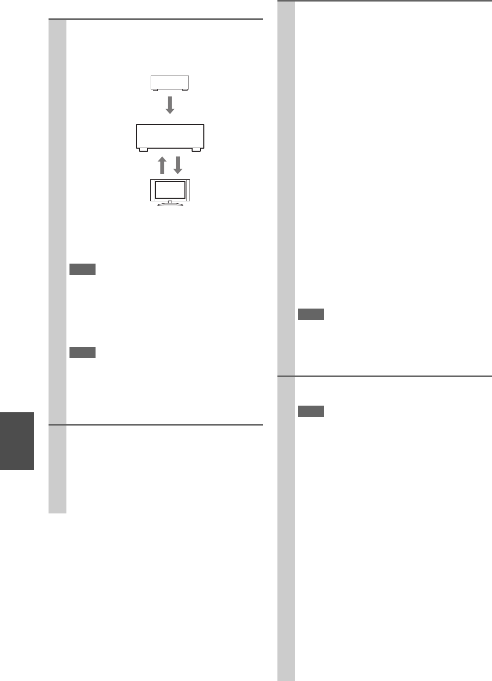
108
En
■How to connect and setup
1Confirm the connecting and setting.
1. Connect the HDMI OUT MAIN jack to the
HDMI input jack of the TV.
2. Connect the audio output from the TV to the
OPTICAL IN 2 jack of the AV controller using
an optical digital cable.
Note
• When you use the audio return channel (ARC) function
with an HDMI (Audio Return Channel) capable TV, this
connection is not required (➔66).
3. Connect the HDMI output of the Blu-ray
Disc/DVD player/recorder to the HDMI IN 1
jack of the AV controller.
Note
• It is necessary to assign the HDMI input when connecting
the Blu-ray Disc/DVD player/recorder to other jacks
(➔51). Do not assign the components connected to the
HDMI IN to the TV/CD input at this time. Appropriate
CEC (Consumer Electronics Control) operation can not be
guaranteed.
2Change each item in the “HDMI” as below:
•HDMI Control(RIHD): On
•Audio Return Channel (ARC): Auto
•Power Control: On
•TV Control: On
See details of each setting (➔66).
Blu-ray Disc/DVD player, etc.
AV controller
TV, projector, etc.
DIGITAL AUDIO
connection
(OPTICAL)
HDMI
connection
HDMI
connection
3Confirm the settings.
1. Turn on the power for all connected components.
2. Turn off the power of the TV, and confirm that
the power of the connected components is turned
off automatically with the link operation.
3. Turn on the power of the Blu-ray Disc/DVD
player/recorder.
4. Start playback of the Blu-ray Disc/DVD
player/recorder, and confirm the following.
• The power of the AV controller is turned on
automatically, and input with the Blu-ray
Disc/DVD player/recorder connected is
selected.
• The power of the TV is turned on automati-
cally, and input with the AV controller con-
nected is selected.
5. Following the operating instructions of the TV,
select “Use the TV speakers” from the menu
screen of the TV, and confirm that the audio is
output from the speakers of the TV, and not from
the speakers connected to the AV controller.
6. Select “Use the speakers connected from the AV
controller” from the menu screen of the TV, and
confirm that the audio is output from the speak-
ers connected to the AV controller, and not from
the TV speakers.
Note
• Perform the above operations when you initially use the
AV controller, when the settings of each component are
changed, when the main power of each component is
turned off, when the power cable is disconnected from the
power supply, or when there has been a power outage.
4Operate with the remote controller.
See the list of available buttons (➔96).
Note
• Audio from DVD-Audio or Super Audio CD may not out-
put from the TV speakers. You will be able to output the
audio from the TV speakers by setting the audio output of
the DVD player to 2ch PCM. (It may not be possible
depending on the player models.)
• Even if you set to output audio on the TV speakers, audio
will be output from the speakers connected to the AV con-
troller when you adjust the volume or switch the input on
the AV controller. To output audio from the TV speakers,
re-do the operations on the TV.
• Do not connect the u cable when connecting to the u
and u audio control compatible components.
• When you select anything other than the HDMI jack
where the AV controller is connected as the input on the
TV, input on the AV controller will be switched to
“TV/CD”.
• The AV controller will automatically power on in conjunc-
tion when it determines it to be necessary. Even if the AV
controller is connected to an p compatible TV or
player/recorder, it will not power on if it is not necessary.
It may not power on in conjunction when the TV is set to
output audio from the TV.
• Linked functions with the AV controller may not work
depending on the model. Operate the AV controller
directly in such cases.
109
En
Firmware Update
There are the following methods to update the firmware:
via network and via USB storage. Please choose either one
that suits your condition. Before you start, carefully read
the update procedure. It will take about 60 minutes to
update the firmware.
■Update via network
You need a wired Internet connection to update the
firmware.
■Update via USB storage (➔111)
Please prepare a USB storage device such as a USB
flash memory stick. You need at least 32 MB of avail-
able space to update the firmware.
Note
• Check the network connection before update.
• Do not touch the cable or any other device connected to the AV
controller during updating process.
• Do not access the AV controller from PC during updating pro-
cess.
• Do not shutdown the power of the AV controller while update.
• The storage media in the USB card reader may not work.
• If the storage device has been partitioned, each section will be
treated as an independent device.
• If the USB mass storage device contains a lot of data, the AV
controller may take a while to read it.
• Operation with all USB mass storage devices including the abil-
ity to power them is not guaranteed.
• Onkyo accepts no responsibility whatsoever for the loss or dam-
age to data stored on a USB mass storage device when that
device is used with the AV controller. Onkyo recommends that
you back up your important music files beforehand.
• If you connect a USB hard disk drive to the USB port, Onkyo
recommends that you use its AC adapter to power it.
• USB hubs and USB devices with hub functions are not sup-
ported. Do not connect your USB mass storage device via a USB
hub.
• USB mass storage devices with security functions are not sup-
ported.
The AV controller allows you to update firmware using net-
work connection on rear panel.
*In this procedure, on-screen display may vary depending on the
model.
Note
• Make sure the AV controller and TV are turned on and Ethernet
cable is connected to rear panel of the AV controller.
• Never unplug or turn off the AV controller during updating pro-
cess.
• Never plug or unplug an HDMI cable and Ethernet cable during
updating process.
• Never unplug the power cord during updating process.
• Do not access the AV controller from PC during updating pro-
cess.
• It will take about 60 minutes to update the firmware.
• The AV controller will retain all your settings after update is fin-
ished.
Before you start
•Check “HDMI Control(RIHD)” setting (➔66). The
update may not be successful if this setting is on.
• Turn off the controller device connected via RS232C and
via Ethernet network.
• Turn off Zone 2 and Zone 3.
• Stop playback of content from Internet radio, iPod, USB
or servers, etc.
■How to turn off RIHD
Update procedure
Limitation of liability
The program and accompanying online documentation
are furnished to you for use at your own risk. Onkyo
will not be liable and you will have no remedy for dam-
ages for any claim of any kind whatsoever concerning
your use of the program or the accompanying online
documentation, regardless of legal theory, and whether
arising in tort or contract. In no event will Onkyo be lia-
ble to you or any third party for any special, indirect,
incidental, or consequential damages of any kind,
including, but not limited to, compensation, reimburse-
ment or damages on account of the loss of present or
prospective profits, loss of data, or for any other reason
whatsoever.
See the Integra web site for latest information.
Updating the Firmware via Network
1In the Main menu select “Hardware Setup”.
2Select “HDMI”.
3Set “HDMI Control(RIHD)” to “Off”.
1Press Receiver followed by Setup on the remote
controller.
Main menu will be displayed on TV screen. Proce-
dures thereafter can also be performed on the AV
controller by using its Setup, arrow, and Enter but-
tons.
2Go to “Hardware Setup” menu.
3Go to “Firmware Update” menu.
Note that the Firmware Update option will be grayed
out about 50 seconds after the AV controller is
turned on. Please wait.
4Select “via NET” and press Enter.

110
En
Troubleshooting
Case1:
If “No Update” is displayed on the front display of the AV
controller, the firmware has already been updated. You do
not need to do anything further.
Case2:
If an error occurs, “Error!! *-** No media” is displayed
on the front display of the AV controller. (Alpha-numeric
characters on the front display are denoted by asterisks.)
See the following table and take appropriate action.
■Errors during update via network
Case3:
If an error occurs during updating process, disconnect then
reconnect the power cord and try again.
Case4:
If Error Code 3-51 is displayed, try the following proce-
dure.
1. Disconnect the power cord then reconnect.
2. Start up the AV controller, and select the NET/USB
selector.
3. After the “Now Initializing” display has changed,
perform the update again.
Case5:
If an error has occurred due to wrong selection of input
sources, turn off and on the AV controller. Then retry the
update.
Case6:
If you do not have a wired connection to the network,
please contact Integra Support (➔112).
5Select “Update” and press Enter.
Updating will begin.
As the updating progresses, the TV screen may dis-
appear depending on the program updated. In this
case, you can see the update progress on the front
display of the AV controller. The TV screen will
reappear when you finish the update and turn on the
AV controller.
6Message “Complete!” appears on the front dis-
play of the AV controller, indicating that the
update has been completed.
7Using On/Standby on the front panel, turn off
and on the AV controller.
Do not use On or Standby on the remote controller.
Congratulations!! Now you have the latest firmware
on the AV controller.
Error Code Description
*-10, *-20 Ethernet cable is not detected. Connect the
cable properly.
*-11, *-13, *-21,
*-28
Internet connection error.
Check the following items:
• Make sure IP address, subnet mask, gateway
address, and DNS server are configured prop-
erly.
• Make sure the router is turned on.
• Make sure the AV controller and the router
are connected with Ethernet cable.
• Make sure the setup configuration of the
router is set properly. See the instruction
manual of the router.
• If your network allows only one client con-
nection and there is any other device already
connected, the AV controller cannot access
the network. Consult your Internet Service
Provider (ISP).
• If your modem does not function as a router,
you will need a router. Depending on your
network, you may need to configure the
proxy server if needed. See the document
provided by your ISP. If you still cannot
access the Internet, DNS or proxy server may
be temporarily down. Contact your ISP.
Others Retry the update procedure from the begin-
ning. If the error persists, please contact
Integra Support (➔112) and provide the error
code.
111
En
The AV controller allows you to update firmware using a
USB storage device.
*In this procedure, on-screen display may vary depending on the
model.
Note
• Make sure the AV controller and TV are turned on.
• Never unplug or turn off the AV controller during updating pro-
cess.
• Never plug or unplug an HDMI cable and Ethernet cable during
updating process.
• Never unplug the USB storage device containing the firmware
file and the power cord during updating process.
• Do not access the AV controller from PC during updating pro-
cess.
• It will take about 60 minutes to update the firmware.
• The AV controller will retain all your settings after update is fin-
ished.
Before you start
• Check “HDMI Control(RIHD)” setting (➔66). The
update may not be successful if this setting is on.
• Turn off the controller device connected via RS232C and
via Ethernet network.
• Turn off Zone 2 and Zone 3.
• Stop playback of content from Internet radio, iPod, USB
or servers, etc.
■How to turn off RIHD
Update procedure
Updating the Firmware via USB
1In the Main menu select “Hardware Setup”.
2Select “HDMI”.
3Set “HDMI Control(RIHD)” to “Off”.
1Connect a USB storage device to your PC. If
there is any data in the USB storage device,
remove it.
2Download the firmware file from the Integra
web site. The file name is as follows:
ONKAVR0001_*******.zip
Unzip the downloaded file. The following three
files are created:
ONKAVR0001_*******.of1
ONKAVR0001_*******.of2
ONKAVR0001_*******.of3
3Copy the extracted files to the USB storage
device. Be careful not to copy the zip file.
4Remove the USB storage device from your PC
and connect it to the USB port on the AV con-
troller.
When the AV controller has two USB ports, you
can use either one.
5Make sure the AV controller and TV are turned
on.
If the AV controller is in standby mode, press
On/Standby on the AV controller to light up the
front display.
6Select the USB input source.
“Now Initializing” is displayed on the front dis-
play and then the name of the USB storage device
is displayed. It will take 20 to 30 seconds to recog-
nize the USB storage device.
7Press Receiver followed by Setup on the
remote controller.
Main menu will be displayed on TV screen. Pro-
cedures thereafter can also be performed on the
AV controller by using its Setup, arrow, and
Enter buttons.
8Go to “Hardware Setup” menu.
9Go to “Firmware Update” menu.
10 Select “via USB” and press Enter.
11 Select “Update” and press Enter.
Updating will begin.
As the updating progresses, the TV screen may
disappear depending on the program updated. In
this case, you can see the update progress on the
front display of the AV controller. The TV screen
will reappear when you finish the update and turn
on the AV controller.
Do not turn off the AV controller and do not
remove the USB storage device during updating
process.
12 Message “Complete!” appears on the front dis-
play of the AV controller, indicating that the
update has been completed.
13 Using On/Standby on the front panel, turn off
the AV controller and then remove the USB
storage device.
*Do not use On or Standby on the remote controller.
14 Press On/Standby to turn on the AV controller.
Congratulations!! Now you have the latest firm-
ware on the AV controller.

112
En
Troubleshooting
Case1:
If “No Update” is displayed on the front display of the AV
controller, the firmware has already been updated. You do
not need to do anything further.
Case2:
If an error occurs, “Error!! *-** No media” is displayed
on the front display of the AV controller. (Alpha-numeric
characters on the front display are denoted by asterisks.)
See the following table and take appropriate action.
■Errors during update via USB
Case3:
If an error occurs during updating process, disconnect then
reconnect the power cord and try again.
Case4:
If Error Code 3-51 is displayed, try the following proce-
dure.
1. Disconnect the power cord then reconnect.
2. Start up the AV controller, and select the NET/USB
selector.
3. After the “Now Initializing” display has changed,
perform the update again.
Case5:
If an error has occurred due to wrong selection of input
sources, turn off and on the AV controller. Then retry the
update.
Error Code Description
*-10, *-20 USB storage device is not detected. Make sure
the USB flash memory or USB cable is prop-
erly connected to the USB port. If the USB
storage device has its own power supply, use it
to power the USB storage device.
*-14 The firmware file is not found in the root
folder of the USB storage device, or the firm-
ware file is for other model. Retry download
following instructions at the support website.
If the error persists, please contact Integra
Support and provide the error code.
Others Retry the update procedure from the begin-
ning. If the error persists, please contact
Integra Support and provide the error code.
ONKYO CORPORATION
2-1, Nisshin-cho, Neyagawa-shi, OSAKA 572-8540, JAPAN
The Americas
Integra Division of ONKYO U.S.A. CORPORATION
18 Park Way, Upper Saddle River, N.J. 07458, U.S.A.
Tel: 800-225-1946, 201-818-9200
Fax: 201-785-2650
Hours: M-F 9am-8pm/Sat-Sun 10am-4pm ET
<http://www.integrahometheater.com/>
Asia, Oceania
Please contact an ONKYO distributor referring to Onkyo SUPPORT
site.
<http://www.intl.onkyo.com/support/local_support/index.html>
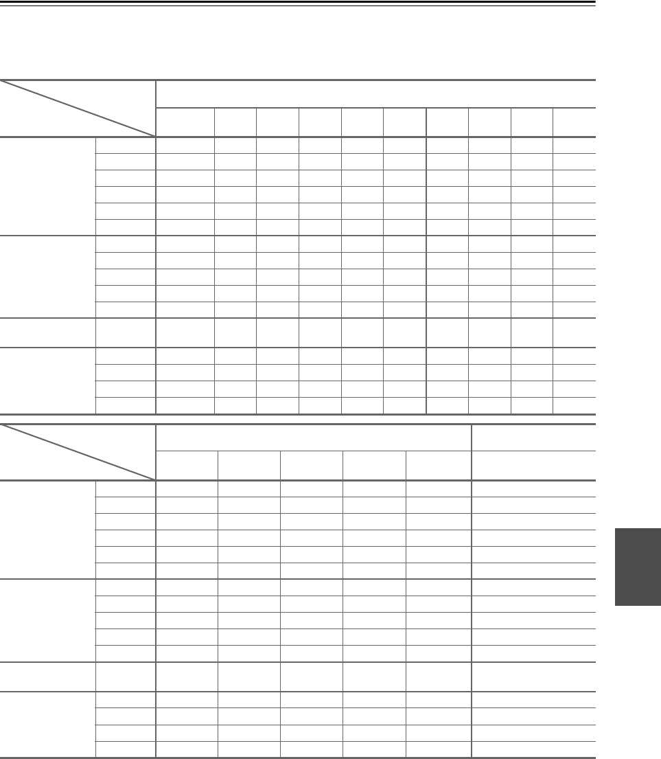
113
En
Video Resolution Chart
The following tables show how video signals at different resolutions are output by the AV controller.
NTSC/PAL
✔: Output
*1 The superimposed menus cannot be displayed.
*2 The superimposed menus are displayed at only 60 Hz.
HDMI
1080p/24 1080p 1080i 720p 480p/
576p
480i/
576i
SXGA XGA SVGA VGA
HDMI 1080p/24 ✔✔✔✔✔
1080p ✔✔✔✔✔
1080i ✔✔✔✔✔
720p ✔✔✔✔✔
480p/576p ✔✔✔✔✔
480i/576i ✔ ✔✔✔✔✔
Component 1080p ✔✔✔✔✔
1080i ✔✔✔✔✔
720p ✔✔✔✔✔
480p/576p ✔✔✔✔✔
480i/576i ✔ ✔✔✔✔✔
S-Video
Composite
480i/576i ✔ ✔✔✔✔✔
PC IN
(Analog RGB)
SXGA ✔*2 ✔*2 ✔*2 ✔*2 ✔*2
XGA ✔*2 ✔*2 ✔*2 ✔*2 ✔*2
SVGA ✔*2 ✔*2 ✔*2 ✔*2 ✔*2
VGA ✔*2 ✔*2 ✔*2 ✔*2 ✔*2
Component S-Video
Composite
1080p 1080i 720p 480p/576p 480i/576i 480i/576i
HDMI 1080p/24
1080p
1080i
720p
480p/576p
480i/576i
Component 1080p ✔*1 ✔✔✔
1080i ✔✔✔
720p ✔✔✔
480p/576p ✔✔✔
480i/576i ✔✔✔✔
S-Video
Composite
480i/576i ✔✔✔✔ ✔
PC IN
(Analog RGB)
SXGA ✔*2 ✔*2 ✔*2
XGA ✔*2 ✔*2 ✔*2
SVGA ✔*2 ✔*2 ✔*2
VGA ✔*2 ✔*2 ✔*2
Output
Input
Output
Input

114
En
Memo

115
En
Memo

SN 29400447
(C) Copyright 2010 ONKYO CORPORATION Japan. All rights reserved. * 2 9 4 0 0 4 4 7 *
Y1007-1
Integra Division of
ONKYO U.S.A. CORPORATION
18 park Way, Upper Saddle River, N.J. 07458, U.S.A.
Tel: 800-225-1946, 201-818-9200 Fax: 201-785-2650 http://www.integrahometheater.com
Integra Division of
ONKYO CORPORATION
Sales & Product Planning Div.: 2-1, Nisshin-cho, Neyagawa-shi, OSAKA 572-8540, JAPAN
Tel: 072-831-8023 Fax: 072-831-8163
En
