Bryant Durapac Series 580F Users Manual
580F to the manual c5b02d68-f692-4215-a87a-f02f16d460e3
2015-02-02
: Bryant Bryant-Durapac-Series-580F-Users-Manual-412088 bryant-durapac-series-580f-users-manual-412088 bryant pdf
Open the PDF directly: View PDF ![]() .
.
Page Count: 64

Cancels: II 580F-36-3 II 580F-36-4
1/15/04
IMPORTANT — READ BEFORE INSTALLING
1. Read and become familiar with these installation
instructions before installing this unit (Fig. 1A and
1B).
2. Be sure the installation conforms to all applicable lo-
cal and national codes.
3. These instructions contain important information for
the proper maintenance and repair of this equipment.
Retain these instructions for future use.
CONTENTS
Page
SAFETY CONSIDERATIONS . . . . . . . . . . . . . . . . . . . . . . . . . 1
INSTALLATION . . . . . . . . . . . . . . . . . . . . . . . . . . . . . . . . . .1-36
I. Step 1 — Provide Unit Support. . . . . . . . . . . . . . . . . 1
II. Step 2 — Field Fabricate Ductwork . . . . . . . . . . . . . 4
III. Step 3 — Install External Trap for
Condensate Drain . . . . . . . . . . . . . . . . . . . . . . . . . . . 4
IV. Step 4 — Rig and Place Unit. . . . . . . . . . . . . . . . . . . 4
V. Step 5 — Install Flue Hood . . . . . . . . . . . . . . . . . . . . 6
VI. Step 6 — Install Gas Piping . . . . . . . . . . . . . . . . . . . 6
VII. Step 7 — Make Electrical Connections . . . . . . . . . 10
VIII. Step 8 — Adjust Factory-Installed Options. . . . . . 14
IX. Step 9 — Adjust Evaporator-Fan Speed . . . . . . . . 24
PRE-START-UP. . . . . . . . . . . . . . . . . . . . . . . . . . . . . . . . . . . 37
START-UP . . . . . . . . . . . . . . . . . . . . . . . . . . . . . . . . . . . . .37-47
SERVICE . . . . . . . . . . . . . . . . . . . . . . . . . . . . . . . . . . . . . .47-52
TROUBLESHOOTING. . . . . . . . . . . . . . . . . . . . . . . . . . . .53-57
APPENDIX A — ECONOMI$ER+ LABEL . . . . . . . . . . . 58, 59
APPENDIX B — JOB SPECIFIC ECONOMI$ER+
CONFIGURATION SETTINGS . . . . . . . . . . . . . . . . . . . . . 60
INDEX . . . . . . . . . . . . . . . . . . . . . . . . . . . . . . . . . . . . . . . . . . 61
START-UP CHECKLIST . . . . . . . . . . . . . . . . . . . . . . . . . . CL-1
SAFETY CONSIDERATIONS
Installation and servicing of air-conditioning equipment can
be hazardous due to system pressure and electrical compo-
nents. Only trained and qualified service personnel should
install, repair, or service air-conditioning equipment.
Untrained personnel can perform basic maintenance func-
tions of cleaning coils and filters and replacing filters. All
other operations should be performed by trained service per-
sonnel. When working on air-conditioning equipment,
observe precautions in the literature, tags and labels
attached to the unit, and other safety precautions that apply.
Follow all safety codes. Wear safety glasses and work gloves.
Use quenching cloth for unbrazing operations. Have fire
extinguishers available for all brazing operations.
INSTALLATION
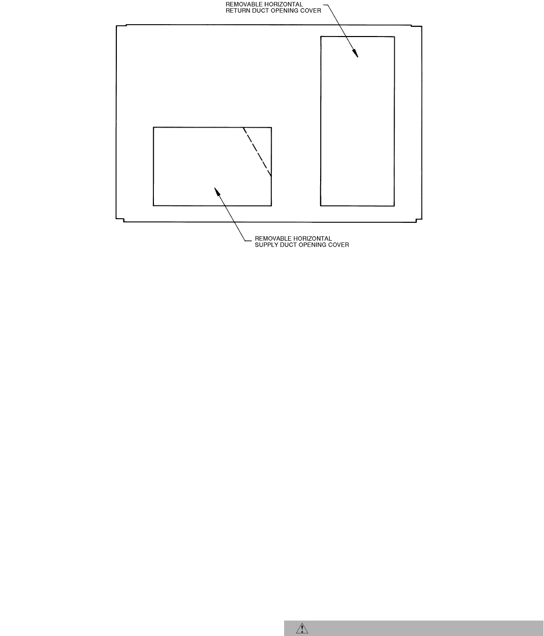
Unit is shipped in the vertical duct configuration. To convert to
horizontal configuration, remove screws from side duct open-
ing covers and remove covers. Using the same screws, install
covers on vertical duct openings with the insulation-side down.
Seals around duct openings must be tight. See Fig. 2.
Confirm before installation of unit that voltage, amperage
and circuit protection requirements listed on unit data plate
agree with power supply provided.
I. STEP 1 — PROVIDE UNIT SUPPORT
A. Roof Curb
Assemble and install accessory roof curb in accordance with
instructions shipped with curb. See Fig. 3. Install insulation,
cant strips, roofing felt, and counter flashing as shown. Duct-
work must be attached to curb, not to the unit. The accessory
thru-the-bottom power and gas connection package must be
installed before the unit is set on the roof curb. If field-
installed (thru-the-roof curb) gas connections are desired, use
factory-supplied 3/4-in. pipe coupling and gas plate assembly
to mount the thru-the-roof curb connection to the roof curb.
Gas connections and power connections to the unit must be
field installed after the unit is installed on the roof curb.
If electric and control wiring is to be routed through the
basepan, attach the accessory thru-the-bottom service con-
nections to the basepan in accordance with the accessory
installation instructions.
IMPORTANT: The gasketing of the unit to the roof curb is
critical for a watertight seal. Install gasket supplied with the
roof curb as shown in Fig. 3. Improperly applied gasket can
result in air leaks and poor unit performance.
Curb should be level. Unit leveling tolerances are shown in
Fig. 4. This is necessary for unit drain to function properly.
Refer to Accessory Roof Curb Installation Instructions for
additional information as required.
WARNING: Disconnect gas piping from unit when
leak testing at pressure greater than 1/2 psig. Pres-
sures greater than 1/2 psig will cause gas valve damage
resulting in hazardous condition. If gas valve is sub-
jected to pressure greater than 1/2 psig, it must be
replaced before use. When pressure testing field-
supplied gas piping at pressures of 1/2 psig or less, a
unit connected to such piping must be isolated by man-
ually closing the gas valve.
WARNING: Before performing service or mainte-
nance operations on unit, turn off main power switch
to unit and install a lockout tag. Electrical shock could
cause personal injury.
CAUTION: Ensure voltage listed on unit data plate
agrees with electrical supply provided for the unit.
installation, start-up and
service instructions
SINGLE PACKAGE ROOFTOP
GAS HEATING/ELECTRIC COOLING UNITS
580F
Dura
Pac
Series
Sizes 036-073
3 to 6 Tons
—2—
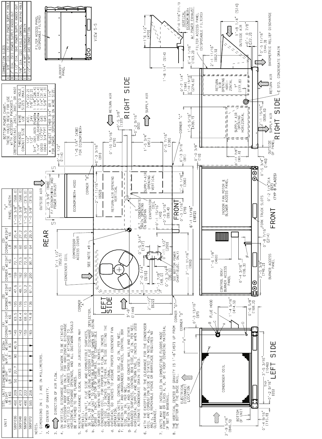
Fig. 1A — Base Unit Dimensions — 580F036-072
—3—
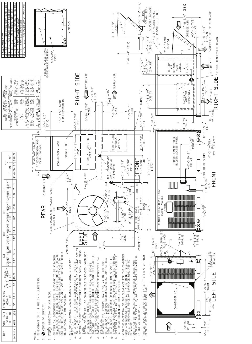
Fig. 1B — Base Unit Dimensions — 580F073
—4—
B. Slab Mount (Horizontal Units Only)
Provide a level concrete slab that extends a minimum of 6 in.
beyond unit cabinet. Install a gravel apron in front of condenser
coil air inlet to prevent grass and foliage from obstructing airflow.
NOTE: Horizontal units may be installed on a roof curb if
required.
C. Alternate Unit Support
A non-combustible sleeper rail can be used in the unit curb
support area. If sleeper rails cannot be used, support the
long sides of the unit with a minimum of 3 equally spaced
4-in. x 4-in. pads on each side.
II. STEP 2 — FIELD FABRICATE DUCTWORK
Secure all ducts to roof curb and building structure on verti-
cal ducted units. Do not connect ductwork to unit. For hori-
zontal applications, field-supplied flanges should be attached
to horizontal duct openings and all ductwork should be
secured to the flanges. Insulate and weatherproof all exter-
nal ductwork, joints, and roof openings with counter flashing
and mastic in accordance with applicable codes.
Ducts passing through an unconditioned space must be insu-
lated and covered with a vapor barrier.
If a plenum return is used on a vertical unit, the return
should be ducted through the roof deck to comply with appli-
cable fire codes.
A minimum clearance is not required around ductwork. Cab-
inet return air static shall not exceed –.20 in. wg with
economizer or –.45 in. wg without economizer.
These units are designed for a minimum continuous heating
return-air temperature of 50 F (dry bulb), or an intermittent
operation down to 45 F (dry bulb), such as when used with a
night set-back thermostat.
To operate at lower return-air temperatures, a field-supplied
outdoor air temperature control must be used to initiate both
stages of heat when the temperature is below 45 F. Indoor
comfort may be compromised when these lower air tempera-
tures are used with insufficient heating temperature rise.
III. STEP 3 — INSTALL EXTERNAL TRAP FOR CONDEN-
SATE DRAIN
The unit’s 3/4-in. condensate drain connections are located on
the bottom and side of the unit. Unit discharge connections do
not determine the use of drain connections; either drain con-
nection can be used with vertical or horizontal applications.
When using the standard side drain connection, make sure
the plug (Red) in the alternate bottom connection is tight
before installing the unit.
To use the bottom drain connection for a roof curb installation,
relocate the factory-installed plug (Red) from the bottom con-
nection to the side connection. The center drain plug looks like
a star connection, however it can be removed with a 1/2-in.
socket drive. See Fig. 5A. The piping for the condensate drain
and external trap can be completed after the unit is in place.
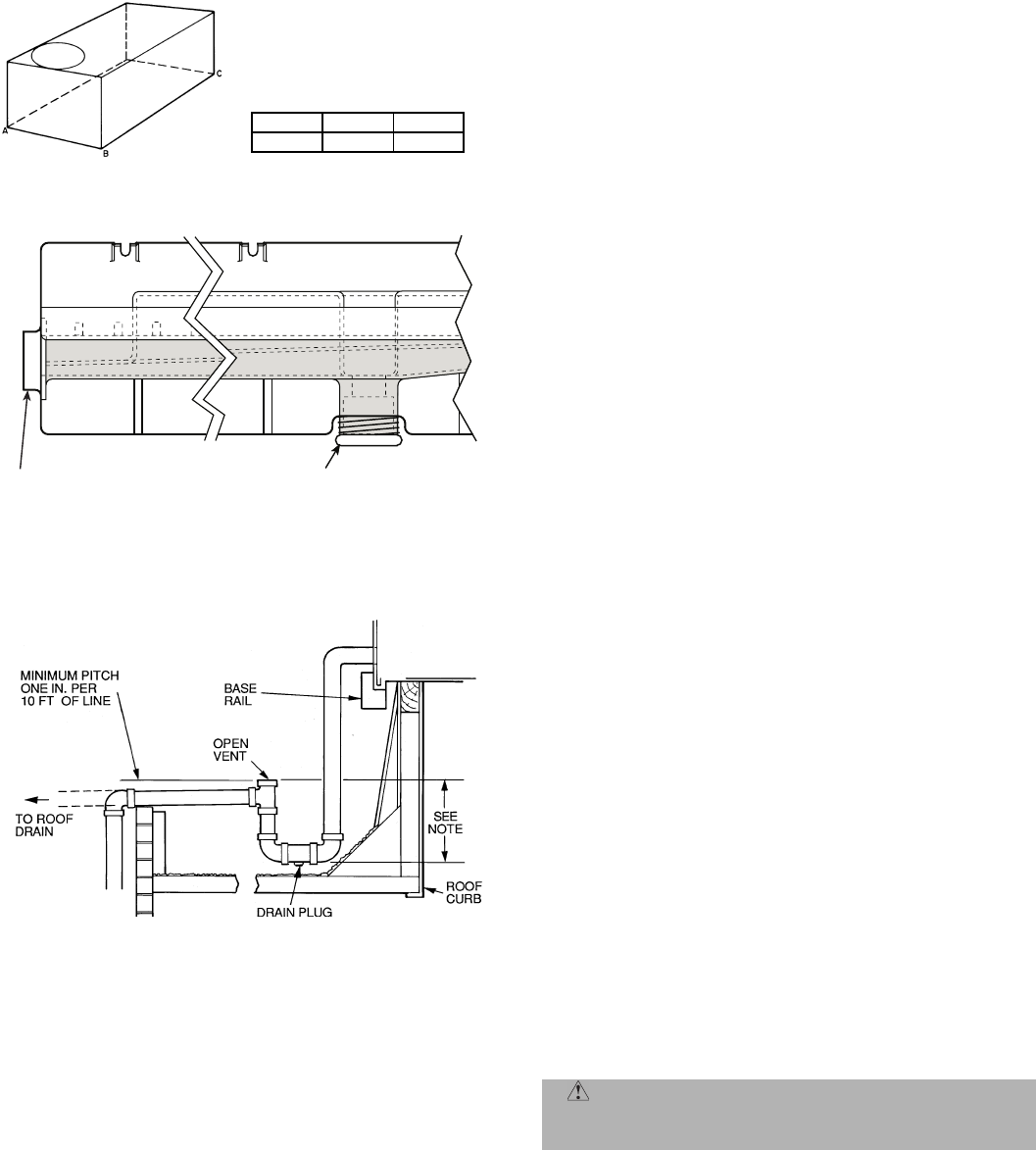
All units must have an external trap for condensate drainage.
Install a trap at least 4-in. deep and protect against freeze-up.
If drain line is installed downstream from the external trap,
pitch the line away from the unit at 1 in. per 10 ft of run. Do
not use a pipe size smaller than the unit connection (3/4 in.).
See Fig. 5B.
IV. STEP 4 — RIG AND PLACE UNIT
Inspect unit for transportation damage. File any claim with
transportation agency. Keep unit upright and do not drop.
Spreader bars are not required if top crating is left on unit.
Rollers may be used to move unit across a roof. Level by
using unit frame as a reference. See Table 1 and Fig. 6 for
additional information.
Lifting holes are provided in base rails as shown in Fig. 1A
and 1B. Refer to rigging instructions on unit.
A. Positioning
Maintain clearance around and above unit to provide mini-
mum distance from combustible materials, proper airflow,
and service access. See Fig. 1A and 1B. A properly positioned
unit will have the following clearances between unit and roof
curb: 1/4-in. clearance between roof curb and base rails on
each side and duct end of unit; 1/4-in. clearance between roof
curb and condenser coil end of unit. (See Fig. 3, section C-C.)
CAUTION: All panels must be in place when rigging.
Fig. 2 — Horizontal Conversion Panels
—5—
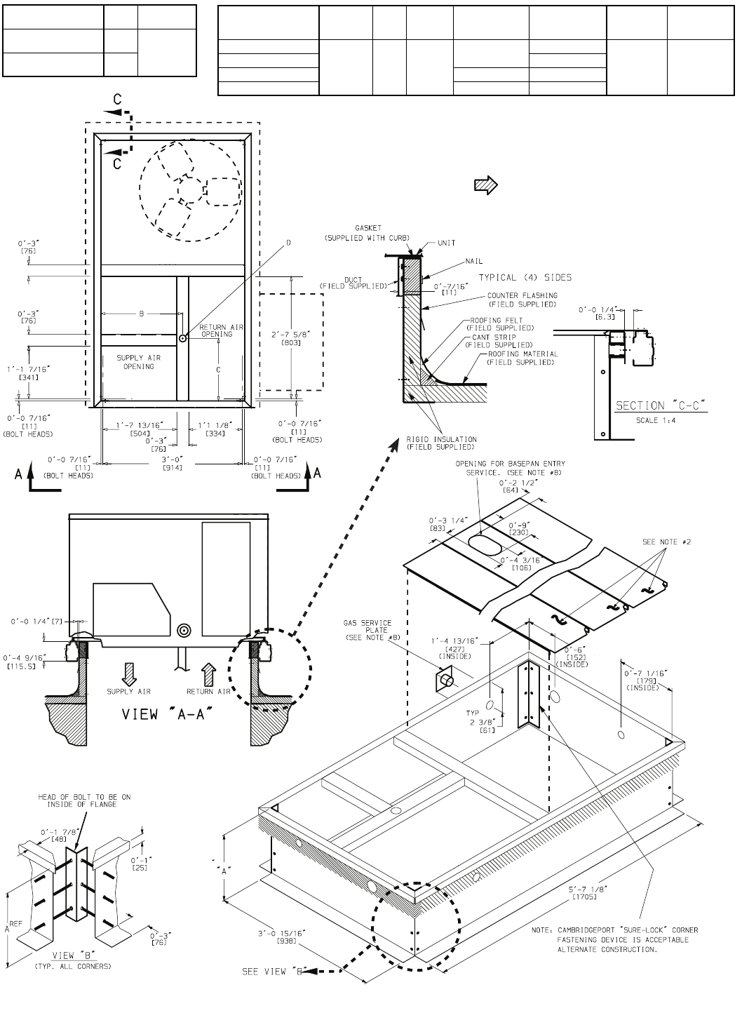
Fig. 3 — Roof Curb
ROOF CURB
ACCESSORY A UNIT SIZE
CRRFCURB001A01 1′-2″
[356] 580F
036-073
CRRFCURB002A01 2′-0″
[610]
NOTES:
1. Roof curb accessory is shipped disassembled.
2. Insulated panels.
3. Dimensions in [ ] are in millimeters.
4. Roof curb, galvanized steel.
5. Attach ductwork to curb (flanges of duct rest on curb).
6. Service clearance: 4 ft on each side.
7. Direction of airflow.
8. Connector packages CRBTMPWR001A01 and 2A01 are for
thru-the-curb type gas. Packages CRBTMPWR003A01 and
4A01 are for thru-the-bottom type gas connections.
CONNECTOR
PKG. ACCY. BC
DALT
DRAIN
HOLE
GAS POWER CONTROL ACCESSORY
POWER
CRBTMPWR001A01
1′-911/16
″
[551]
1′-4″
[406]
13/4
″
[44.5]
3/4
″ [19] NPT
3/4
″[19] NPT
1/2
″
[12.7]
NPT
1/2
″
[12.7]
NPT
CRBTMPWR002A01 11/4
″[31.7]
CRBTMPWR003A01 1/2
″ [12.7] NPT 3/4
″[19] NPT
CRBTMPWR004A01 3/4
″ [19] NPT 11/4
″[31.7]
—6—
Do not install unit in an indoor location. Do not locate unit
air inlets near exhaust vents or other sources of contami-
nated air.
Be sure that unit is installed such that snow will not block
the combustion intake or flue outlet.
Unit may be installed directly on wood flooring or on Class
A, B, or C roof-covering material when roof curb is used.
Although unit is weatherproof, guard against water from
higher level runoff and overhangs.
Flue vent discharge must have a minimum horizontal clear-
ance of 4 ft from electric and gas meters, gas regulators, and
gas relief equipment.
Minimum distance between unit and other electrically live
parts is 48 inches.
Flue gas can deteriorate building materials. Orient unit such
that flue gas will not affect building materials.
Adequate combustion-air space must be provided for
proper operation of this equipment. Be sure that installation
complies with all local codes and Section 5.3, Air for Combus-
tion and Ventilation, NFGC (National Fuel Gas Code), and
ANSI (American National Standards Institute) Z223.1, and
NFPA (National Fire Protection Association) 54 TIA-54-84-1.
In Canada, installation must be in accordance with the
CAN1-B149 installation codes for gas burning appliances.
After unit is in position, remove rigging skids and shipping
materials.
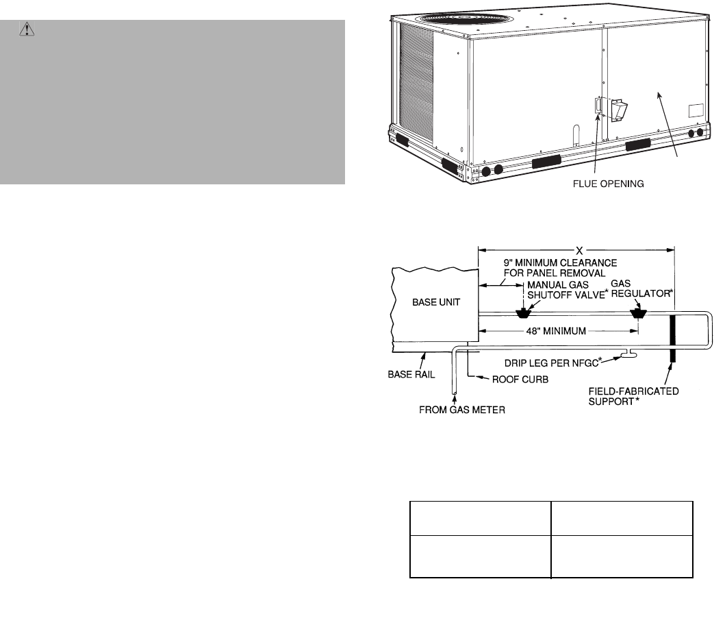
V. STEP 5 — INSTALL FLUE HOOD
Flue hood is shipped screwed to the basepan beside the
burner compartment access panel. Remove from shipping
location and using screws provided, install flue hood and
screen in location shown in Fig. 7.
VI. STEP 6 — INSTALL GAS PIPING
Unit is equipped for use with type of gas shown on name-
plate. Refer to local building codes, or in the absence of local
codes, to ANSI Z223.1 entitled National Fuel Gas Code. In
Canada, installation must be in accordance with the
CAN1.B149.1 and CAN1.B149.2 installation codes for gas
burning appliances.
For natural gas applications, gas pressure at unit gas con-
nection must not be less than 4 in. wg or greater than
13.0 in. wg while unit is operating. On 580F048,060,072 high
heat units, the gas pressure at unit gas connection must not
be less than 5 in. wg or greater than 13 in. wg while the unit
is operating. For propane applications, the gas pressure
must not be less than 5 in. wg or greater than 13 in. wg at
the unit connection.
Size gas supply piping for 0.5 in. wg maximum pressure
drop. Do not use supply pipe smaller than unit gas connec-
tion. Support gas piping as shown in the table in Fig. 8. For
example, a 3/4-in. gas pipe must have one field-fabricated
support beam every 8 ft. Therefore, an 18-ft long gas pipe
would have a minimum of 2 support beams, a 48-ft long pipe
would have a minimum of 6 support beams.
See Fig. 8 for typical pipe guide and locations of external
manual main shutoff valve.
CAUTION: When connecting the gas line to the
unit gas valve, the installer MUST use a backup
wrench to prevent valve damage.
MAXIMUM ALLOWABLE
DIFFERENCE (in.)
A-B B-C A-C
0.5 1.0 1.0
Fig. 4 — Unit Leveling Tolerances
DRAIN PLUGHORIZONTAL
DRAIN PLUG
NOTE: Drain plug is shown in factory-installed position.
Fig. 5A — Condensate Drain Pan
NOTE: Trap should be deep enough to offset maximum unit static dif-
ference. A 4-in. trap is recommended.
Fig. 5B — External Trap Condensate Drain
—7—
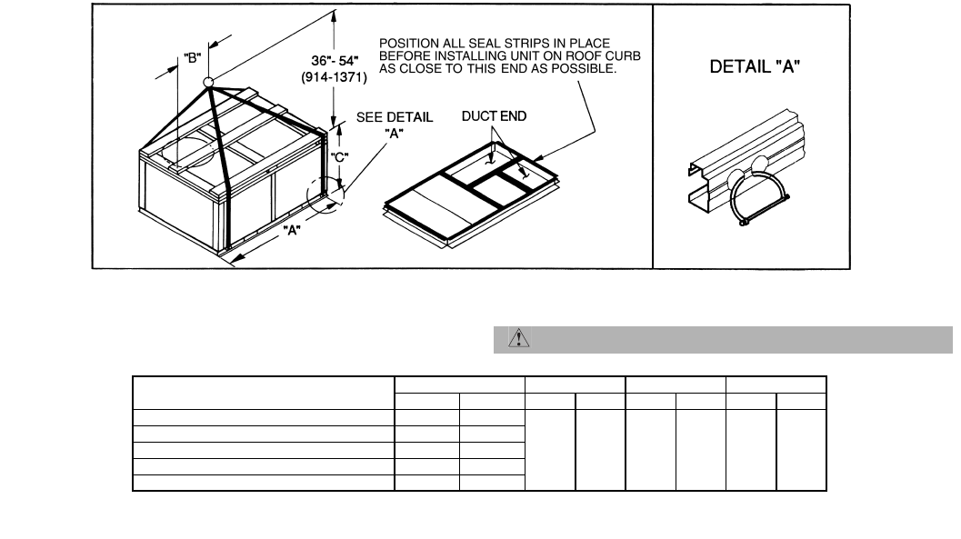
NOTES:
1. Dimensions in ( ) are in millimeters.
2. Hook rigging shackles through holes in base rail, as shown in detail “A.”
Holes in base rails are centered around the unit center of gravity. Use
wooden top skid when rigging to prevent rigging straps from damaging unit.
3. Unit weights do not include economizer. See Table 1 for economizer weights.
CAUTION: All panels must be in place when rigging.
Fig. 6 — Rigging Details
UNIT 580F MAX WEIGHT “A” “B” “C”
Lb Kg in. mm in. mm in. mm
036 510 231
73.69 1872 37.50 953 33.35 845
048 520 236
060 540 245
072 615 279
073 665 302

—8—
Table 1 — Physical Data
LEGEND
*Evaporator coil fin material/condenser coil fin material. Contact your local rep-
resentative for details about coated fins.
†Weight of 14-in. roof curb.
**Single phase/three-phase.
††Rollout switch lockout is manually reset by interrupting power to unit or reset-
ting thermostat.
||California rated three-phase high heat models.
***Three phase standard high-heat models have heating input values as shown.
Single phase standard high heat models have one-stage heating with heating
input values as follows:
580FJV036115 — 115,000 Btuh
580FJV048150 — 150,000 Btuh
580FJV060150 — 150,000 Btuh
†††California SCAQMD compliant Low NOxmodels have combustion products
that are controlled to 40 nanograms per joule or less.
UNIT SIZE 580F 036 048 060 072 073
NOMINAL CAPACITY (tons)34566
OPERATING WEIGHT (lb)
Unit
Al/Al*460 470 490 565 615
Al/Cu*465 476 497 576 —
Cu/Cu*468 482 505 587 —
Economizer
EconoMi$er+ 50 50 50 50 50
Roof Curb† 115 115 115 115 115
COMPRESSOR Reciprocating Scroll
Quantity 11111
No. Cylinders (per Circuit)22222
Oil (oz) 50 50 50 54 60
REFRIGERANT TYPE R-22
Expansion Device Fixed Orifice Metering Device
Operating Charge (lb-oz)
Circuit 1 4-4 6-6 6-14 9-0 11-0
Circuit 2 —————
CONDENSER COIL Enhanced Copper Tubes, Aluminum Lanced Fins
Rows...Fins/in. 1...17 2...17 2...17 2...17 2...17
Total Face Area (sqft)8.36 8.36 10.42 10.42 16.5
CONDENSER FAN Propeller Type
Nominal Cfm3500 4000 4000 4000 4100
Quantity...Diameter (in.)1...22.0 1...22.0 1...22.0 1...22.0 1...22.0
Motor Hp...Rpm1/4...1100 1/4...1100 1/4...1100 1/4...1100 1/4...1100
Watts Input (Total)325 325 325 325 320
EVAPORATOR COIL Enhanced Copper Tubes, Aluminum Double-Wavy Fins
Rows...Fins/in. 2...15 2...15 3...15 4...15 4...15
Total Face Area (sqft)4.17 5.5 5.5 5.5 5.5
EVAPORATOR FAN Centrifugal Type
Quantity...Size(in.)Std 1...10 x 10 1...10 x 10 1...11 x 10 1...10 x 10 1...10 x 10
Alt 1...10 x 10 1...10 x 10 1...10 x 10 — —
High-Static 1...10 x 10 1...10 x 10 1...11 x 10 1...10 x 10 1...10 x 10
Type Drive Std Direct Direct Direct Belt Belt
Alt Belt Belt Belt — —
High-Static Belt Belt Belt Belt Belt
Nominal Cfm1200 1600 2000 2100 2100
MaximumContinuous BhpStd.34 .75 1.20 2.40 2.40
Alt 1.20 1.20 1.30/2.40** — —
High-Static 2.40 2.40 2.90 2.90 2.90
Motor FrameSizeStd48 48 48 56 56
Alt 48 48 56 — —
High-Static 56 56 56 56 56
Nominal RpmHigh/Low (Direct Drive)Std 860/800 1075/970 1075/970 — —
Alt —————
High-Static —————
Fan RpmRange Std — — — 1070-1460 1070-1460
Alt 685-1045 770-1175 8778-1192 — —
High-Static 1075-1455 1075-1455 1300-1685 1300-1685 1300-1685
Motor Bearing Type Ball Ball Ball Ball Ball
MaximumAllowable Rpm2100 2100 2100 2100 2100
Motor Pulley PitchDiameter Min/Max (in.)Std — — — 2.8/3.8 2.8/3.8
Alt 1.9/2.9 1.9/2.9 2.4/3.4 — —
High-Static 2.8/3.8 2.8/3.8 3.4/4.4 3.4/4.4 3.4/4.4
Nominal Motor Shaft Diameter (in.)Std 1/21/21/25/85/8
Alt 1/21/25/8——
High-Static 5/85/85/85/87/8
Fan Pulley PitchDiameter (in.)Std ———4.54.5
Alt 4.5 4.0 4.5 — —
High-Static 4.5 4.5 4.5 4.5 4.5
Belt, Quantity...Type...Length(in.)Std — — — 1...A...40 1...A...40
Alt 1...A...34 1...A...34 1...A...39 — —
High-Static 1...A...39 1...A...39 1...A...40 1...A...40 1...A...40
Pulley Center Line Distance (in.)Std — — — 14.7-15.5 14.7-15.5
Alt 10.0-12.4 10.0-12.4 14.7-15.5 — —
High-Static 10.0-12.4 10.0-12.4 14.7-15.5 14.7-15.5 14.7-15.5
Speed Change per Full Turn of Std ———8080
Movable Pulley Flange (rpm) Alt 48 70 80 — —
High-Static 65 65 60 60 60
MovablePulleyMaximumFull Turns Std ——— 55
FromClosed Position Alt 556——
High-Static 66555
Factory Setting Std ——— 33
Alt 333——
High-Static 31/231/231/231/231/2
Factory Speed Setting (rpm) Std — — — 1226 1226
Alt 829 932 1035 — —
High-Static 1233 1233 1416 1416 1416
Fan Shaft Diameter at Pulley (in.)5/85/85/85/85/8
Al — Aluminum
Bhp— Brake Horsepower
Cu — Copper
—9—
Table 1 — Physical Data (cont)
LEGEND
*Evaporator coil fin material/condenser coil fin material. Contact your local rep-
resentative for details about coated fins.
†Weight of 14-in. roof curb.
**Single phase/three-phase.
††Rollout switch lockout is manually reset by interrupting power to unit or reset-
ting thermostat.
||California rated three-phase high heat models.
***Three phase standard high-heat models have heating input values as shown.
Single phase standard high heat models have one-stage heating with heating
input values as follows:
580FJV036115 — 115,000 Btuh
580FJV048150 — 150,000 Btuh
580FJV060150 — 150,000 Btuh
†††California SCAQMD compliant Low NOxmodels have combustion products
that are controlled to 40 nanograms per joule or less.
UNIT SIZE 580F 036 048 060 072 AND 073
FURNACE SECTION
Rollout SwitchCutout
Temp(F)†† 195 195 195 195
Burner Orifice Diameter
(in. ...drill size)
Natural Gas Std 074 .113...33 .113...33 .113...33 .113...33
114/115 .113...33 .113...33 .113...33 .113...33
149/150 — .129...30 .129...30 .129...30
060N .102...38 .102...38 .102...38 —
090N .102...38 .102...38 .102...38 —
120N — .116...32 .116...32 —
Liquid Propane Alt 074 .089...43 .089...43 .089...43 .089...43
114/115 .089...43 .089...43 .089...43 .089...43
149/150 — .104...37 .104...37 .104...37
060N .082...45 .082...45 .082...45 —
090N .082...45 .082...45 .082...45 —
120N — .094...42 .094...42 —
Thermostat Heat Anticipator
Setting (amps)
208/230 v and 575 Stage 1 .14 .14 .14 .14
Stage 2 .14 .14 .14 .14
460 v Stage 1 .14 .14 .14 .14
Stage 2 .14 .14 .14 .14
Gas Input (Btuh) CA HighOutput 3-Phase Units 114|| 115,000 — — —
149|| — 150,000 150,000 —
Standard Units 074 74,000/— 74,000/— 74,000/— 74,000/—
(Stage 2/Stage 1)115*** 115,000/82,000 115,000/— 115,000/— 115,000/—
150*** — 150,000/120,000 150,000/120,000 150,000/120,000
Low NOx Units 060N††† 60,000 60,000 60,000 —
090N††† 90,000 90,000 90,000 —
120N††† — 120,000 120,000 —
Efficiency (Steady
State)(%) 80 80 80 80
Temperature Rise Range 074 25-55 25-55 25-55 25-55
114/115 55-85 35-65 35-65 35-65
149/150 — 50-80 50-80 50-80
060N 20-50 20-50 20-50 —
090N 30-60 30-60 30-60 —
120N — 40-70 40-70 —
Manifold Pressure (in. wg)
Natural Gas Std 3.5 3.5 3.5 3.5
Liquid Propane Alt 3.5 3.5 3.5 3.5
Gas Valve Quantity 1111
Gas Valve Pressure Range
Psig 0.180-0.487 0.180-0.487 0.180-0.487 0.180-0.487
in. wg 5.0-13.5 5.0-13.5 5.0-13.5 5.0-13.5
Field Gas Connection
Size(in.)1/21/21/21/2
HIGH-PRESSURE SWITCH (psig)
Standard Compressor 450 ± 50 500 ± 50
Internal Relief (Differential)
Cutout 428 428
Reset (Auto.)320 320
LOSS-OF-CHARGE (LOW-PRESSURE SWITCH)(psig)
Cutout 7±3
Reset (Auto.)22 ± 7
FREEZEPROTECTION
THERMOSTAT (F)
Opens 30 ± 5
Closes 45 ± 5
OUTDOOR-AIR INLET SCREENS Cleanable. Screen size and quantity varies with option selected.
RETURN-AIR FILTERS Throwaway
Quantity...Size(in.)2...16 x 25 x 2
Al — Aluminum
Bhp— Brake Horsepower
Cu — Copper
—10—
VII. STEP 7 — MAKE ELECTRICAL CONNECTIONS
A. Field Power Supply
All units except 208/230-v units are factory wired for the
voltage shown on the nameplate. If the 208/230-v unit is to
be connected to a 208-v power supply, the transformer must
be rewired by moving the black wire with the 1/4-in. female
space connector from the 230-volt connection and moving to
the 208-volt 1/4-in. male terminal on the primary side of the
transformer.
Refer to unit label diagram for additional information.
Pigtails are provided for field wire connections. Use factory-
supplied splices or UL (Underwriters’ Laboratories)
approved copper/aluminum connector.
When installing units, provide a disconnect per the NEC.
All field wiring must comply with NEC and local require-
ments.
Install field wiring as follows:
1. Install conduit through side panel openings. Install
conduit between disconnect and control box.
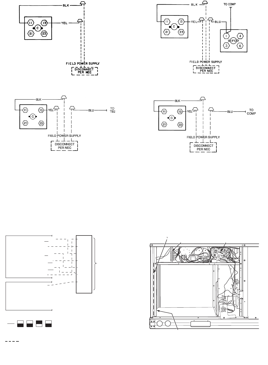
2. Install power lines to terminal connections as shown
in Fig. 9.
Voltage to compressor terminals during operation must be
within voltage range indicated on unit nameplate (see
Tables 2A and 2B). On 3-phase units, voltages between
phases must be balanced within 2% and the current within
10%. Use the formula shown in the legend for Tables 2A and
2B, Note 2 to determine the percent of voltage imbalance.
Operation on improper line voltage or excessive phase imbal-
ance constitutes abuse and may cause damage to electrical
components. Such operation would invalidate any applicable
Bryant warranty.
B. Field Control Wiring
Install a Bryant-approved accessory thermostat assembly
according to installation instructions included with the
accessory. Locate thermostat assembly on a solid wall in the
conditioned space to sense average temperature in accor-
dance with thermostat installation instructions. Connect
thermostat wires to terminal board.
Route thermostat cable or equivalent single leads of colored
wire from subbase terminals through connector on unit to
low-voltage connections (shown in Fig. 10).
NOTE: For wire runs up 50 ft, use no. 18 AWG (American
Wire Gage) insulated wire (35 C minimum). For 50 to 75 ft,
use no. 16 AWG insulated wire (35 C minimum). For over
75 ft, use no. 14 AWG insulated wire (35 C minimum). All
wire larger than no. 18 AWG cannot be directly connected to
the thermostat and will require a junction box and splice at
the thermostat.
Pass the control wires through the hole provided in the cor-
ner post; then feed wires through the raceway built into the
corner post to the 24-v barrier located on the left side of the
control box. See Fig. 11. The raceway provides the UL
required clearance between high-voltage and low-voltage
wiring.
C. Heat Anticipator Settings
Set heat anticipator settings at .14 amp for the first stage
and .14 amp for second-stage heating, when available.
WARNING: Unit cabinet must have an uninter-
rupted, unbroken electrical ground to minimize the possi-
bility of personal injury if an electrical fault should occur.
This ground may consist of electrical wire connected to
unit ground lug in control compartment, or conduit
approved for electrical ground when installed in accor-
dance with NEC (National Electrical Code), ANSI/NFPA,
latest edition, and local electrical codes. Do not use gas
piping as an electrical ground. Failure to follow this
warning could result in the installer being liable for per-
sonal injury of others.BLOWER
ACCESS
PANEL
LEGEND
NFGC — National Fuel Gas Code
*Field supplied.
NOTE: Follow all local codes.
SPACING OF SUPPORTS
Fig. 8 — Gas Piping Guide (WithAccessory
Thru-the-Curb Service Connections)
STEEL PIPE
NOMINAL DIAMETER
(in.)
X
DIMENSION
(feet)
1/26
3/4or 1 8
11/4or larger 10
Fig. 7 — Flue Hood Details
—11—
RACEWAY LOW VOLTAGE
CONNECTIONS
INTEGRATED GAS UNIT
CONTROLLER (IGC)
HOLE IN END PANEL (HIDDEN)
LEGEND
Fig. 9 — Power Wiring Connections
C—Contactor
COMP — Compressor
IFC — Indoor-Fan Contactor
NEC — National Electrical Code
TB — Terminal Block
Fig. 11 — Field Control Wiring Raceway
208/230-1-60 208/230-3-60
460-3-60
(SIZES 072 AND 073)
575-3-60
(SIZES 072 AND 073) 208/230-3-60
575-3-60, 460-3-60
(SIZES 036-060)
WIRE
CONNECTIONS
TO
LOW-VOLTAGE
SECTION
(CONNECTION
BOARD)
COOL STAGE 1
FAN
HEAT STAGE 1
COOL STAGE 2
HEAT STAGE 2
24 VAC HOT
24 VAC COM
N/A
OUTDOOR AIR
SENSOR
Y1/W2
G
W/W1
Y/Y2
O/W2
R
C
S1
S2
THERMOSTAT DIPSWITCH SETTINGS
R
G
Y1
Y2
W1
W2
C
IPD/X
ON
OFF
ABCD
LEGEND
NOTE: Underlined letter indicates active thermostat output when con-
figured for A/C operation.
Fig. 10 — Low-Voltage Connections
Field Wiring
—12—
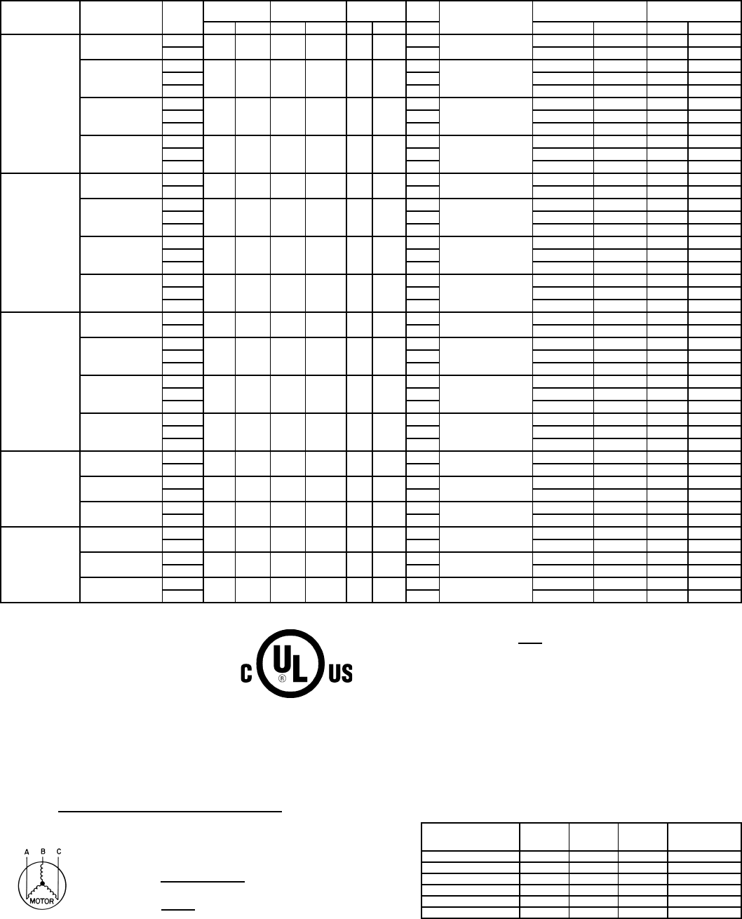
Table 2A — Electrical Data (Without Convenience Outlet)
LEGEND
*Used to determine minimum disconnect per NEC.
†Fuse or HACR circuit breaker.
NOTES:
1. In compliance with NEC requirements for multimotor and combination load equipment (refer
to NEC Articles 430 and 440), the overcurrent protective device for the unit shall be fuse or
HACR breaker. Canadian units may be fuse or circuit breaker.
2. Unbalanced 3-Phase Supply Voltage
Never operate a motor where a phase imbalance in supply voltage is greater than 2%.
Use
the following formula to determine the percent of voltage imbalance.
%Voltage Imbalance
Example: Supply voltage is 460-3-60.
AB =452 v
BC =464 v
AC =455 v
=457
Determine maximum deviation from average voltage.
(AB)457–452=5v
(BC) 464 – 457 =7v
(AC)457–455=2v
Maximum deviation is 7 v.
Determine percent of voltage imbalance.
=1.53%
This amount of phase imbalance is satisfactory as it is below the maximum allowable 2%.
IMPORTANT: If the supply voltage phase imbalance is more than 2%, contact your local electric
utility company immediately.
3. For units with power exhaust: If a single power source is to be used, size wire to include
power exhaust MCA and MOCP. Check MCA and MOCP when power exhaust is powered
through the unit (must be in accordance with NEC and/or local codes). Determine the new
MCA including the power exhaust using the following formula:
MCA New =MCA unit only +MCA of Power Exhaust
For example, using a 580F060 unit with MCA =28.9 and MOCP =35, with
CRPWREXH030A00 power exhaust.
MCA New =28.9 amps +1.6 amps =30.5 amps
If the new MCA does not exceed the published MOCP, then MOCP would not change. The
MOCP in this example is 35 amps, the MCA New is below 35, therefore the MOCP is
acceptable. If “MCA New” is larger than the published MOCP, raise the MOCP to the next
larger size. For separate power, the MOCP for the power exhaust will be 15 amps per NEC.
UNIT
580F
NOMINAL
VOLTAGE
IFM
TYPE
VOLTAGE
RANGE
COMPR
(ea)
OFM
(ea)IFM COMBUSTION
FAN MOTOR
FLA
POWER SUPPLY DISCONNECT
SIZE*
Min Max RLA LRA Hp FLA FLA MCA MOCP† FLA LRA
036
(3Tons)
208/230-1-60 Std 187 254 16.2 96.0 1/41.4 3.5 .6 25.2/25.2 30/30 24/24 106/106
Alt 4.9 26.6/26.6 35/35 26/26 111/111
208/230-3-60
Std
187 254 10.2 75.0 1/41.4
3.5
.6
17.7/17.7 25/25 17/17 85/ 85
Alt 4.9 19.1/19.1 25/25 19/19 90/ 90
High 5.2 19.4/19.4 25/25 19/19 109/109
460-3-60
Std
414 508 4.4 40.0 1/40.8
1.3
.3
7.6 15 7 44
Alt 2.1 8.4 15 8 48
High 2.6 8.9 15 9 57
575-3-60
Std
518 632 3.7 31.0 1/40.8
1.3
.3
5.5 15 6 35
Alt 2.1 6.0 15 7 37
High 2.6 6.3 15 7 56
048
(4Tons)
208/230-1-60 Std 187 254 23.3 118.0 1/41.4 3.5 .6 34.0/34.0 40/40 32/32 129/129
Alt 4.9 35.4/35.4 45/45 34/34 133/133
208/230-3-60
Std
187 254 15.4 90.0 1/41.4
3.5
.6
24.2/24.2 30/30 23/23 101/101
Alt 4.9 25.6/25.6 30/30 25/25 105/105
High 5.2 25.9/25.9 30/30 25/25 124/124
460-3-60
Std
414 508 8.3 45.0 1/40.8
1.8
.3
13.0 20 13 51
Alt 2.1 13.3 20 13 53
High 2.6 13.8 20 13 62
575-3-60
Std
518 632 6.4 36.0 1/40.8
1.8
.3
9.2 15 10 41
Alt 2.1 9.3 15 10 42
High 2.6 9.7 15 10 49
060
(5Tons)
208/230-1-60 Std 187 254 28.8 147.0 1/41.4 5.9 .6 43.3/43.3 60/60 42/42 161/161
Alt 6.6 44.0/44.0 60/60 42/42 184/184
208/230-3-60
Std
187 254 16.0 114.0 1/41.4
5.9
.6
27.3/27.3 35/35 27/27 128/128
Alt 5.2 26.6/26.6 35/35 26/26 148/148
High 7.5 28.9/28.9 35/35 29/29 174/174
460-3-60
Std
414 508 7.4 64.0 1/40.8
3.1
.3
13.2 20 13 71
Alt 2.6 13.5 20 13 81
High 3.4 13.5 20 13 93
575-3-60
Std
518 632 6.2 52.0 1/40.8
3.1
.3
9.7 15 11 58
Alt 2.6 9.9 15 11 65
High 3.4 9.9 15 11 76
072
(6Tons)
208/230-3-60 Std 187 254 20.6 146.0 1/41.4 5.2 .6 32.4/32.4 40/40 31/31 180/180
High 7.5 34.7/34.7 40/40 34/34 205/205
460-3-60 Std 414 508 9.5 73.0 1/40.9 2.6 .3 15.4 20 15 90
High 3.4 16.2 20 16 103
575-3-60 Std 518 632 7.6 58.4 1/40.6 2.6 .3 11.4 15 12 75
High 3.4 11.9 15 13 86
073
(6Tons)
208/230-3-60 Std 187 254 20.6 146.0 1/41.4 5.2 .6 32.4/32.4 40/40 31/31 180/180
High 7.5 34.7/34.7 40/40 34/34 205/205
460-3-60 Std 414 508 9.5 73.0 1/40.9 2.6 .3 15.4 20 15 90
High 3.4 16.2 20 16 103
575-3-60 Std 518 632 7.6 58.4 1/40.6 2.6 .3 11.4 15 12 79
High 3.4 11.9 15 13 86
FLA — Full Load Amps
HACR — Heating, Air Conditioning and Refrigeration
IFM — Indoor (Evaporator) Fan Motor
LRA — Locked Rotor Amps
MCA — Minimum Circuit Amps
MOCP — Maximum Overcurrent Protection
NEC — National Electrical Code
OFM — Outdoor (Condenser) Fan Motor
RLA — Rated Load Amps
=100 x max voltage deviation from average voltage
average voltage
Average Voltage =452 +464 +455
3
=1371
3
%Voltage Imbalance =100 x 7
457
POWER EXHAUST
PART N O.
MCA
(230 v)
MCA
(460 v)
MCA
(575 v)
MOCP
(for separate
power source)
CRPWREXH030A00 1.6 N/A 0.64 15
CRPWREXH021A00 N/A 0.9 N/A 15
CRPWREXH022A00 3.3 N/A 1.32 15
CRPWREXH023A00 N/A 1.8 N/A 15
CRPWREXH028A00 1.7 N/A 0.68 15
CRPWREXH029A00 N/A 1.0 N/A 15
—13—
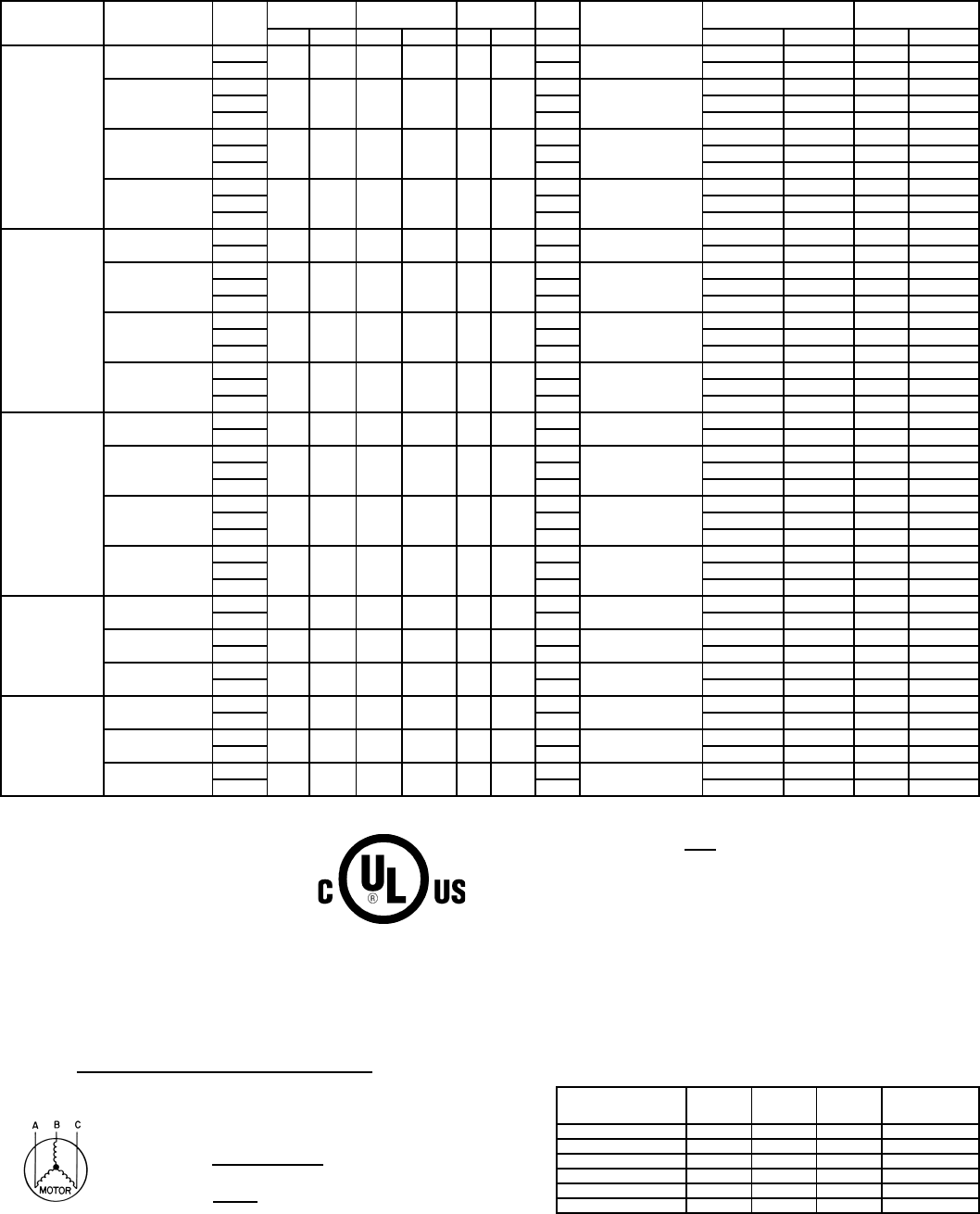
Table 2B — Electrical Data (WithConvenience Outlet)
LEGEND
*Used to determine minimum disconnect per NEC.
†Fuse or HACR circuit breaker.
NOTES:
1. In compliance with NEC requirements for multimotor and combination load equipment (refer
to NEC Articles 430 and 440), the overcurrent protective device for the unit shall be fuse or
HACR breaker. Canadian units may be fuse or circuit breaker.
2. Unbalanced 3-Phase Supply Voltage
Never operate a motor where a phase imbalance in supply voltage is greater than 2%.
Use
the following formula to determine the percent of voltage imbalance.
%Voltage Imbalance
Example: Supply voltage is 460-3-60.
AB =452 v
BC =464 v
AC =455 v
=457
Determine maximum deviation from average voltage.
(AB)457–452=5v
(BC) 464 – 457 =7v
(AC)457–455=2v
Maximum deviation is 7 v.
Determine percent of voltage imbalance.
=1.53%
This amount of phase imbalance is satisfactory as it is below the maximum allowable 2%.
IMPORTANT: If the supply voltage phase imbalance is more than 2%, contact your local electric
utility company immediately.
3. For units with power exhaust: If a single power source is to be used, size wire to include
power exhaust MCA and MOCP. Check MCA and MOCP when power exhaust is powered
through the unit (must be in accordance with NEC and/or local codes). Determine the new
MCA including the power exhaust using the following formula:
MCA New =MCA unit only +MCA of Power Exhaust
For example, using a 580F060 unit with MCA =28.9 and MOCP =35, with
CRPWREXH030A00 power exhaust.
MCA New =28.9 amps +1.6 amps =30.5 amps
If the new MCA does not exceed the published MOCP, then MOCP would not change. The
MOCP in this example is 35 amps, the MCA New is below 35, therefore the MOCP is
acceptable. If “MCA New” is larger than the published MOCP, raise the MOCP to the next
larger size. For separate power, the MOCP for the power exhaust will be 15 amps per NEC.
UNIT
580F
NOMINAL
VOLTAGE
IFM
TYPE
VOLTAGE
RANGE
COMPR
(ea)
OFM
(ea)IFM COMBUSTION
FAN MOTOR
FLA
POWER SUPPLY DISCONNECT
SIZE*
Min Max RLA LRA Hp FLA FLA MCA MOCP† FLA LRA
036
(3Tons)
208/230-1-60 Std 187 254 16.2 96.0 1/41.4 3.5 .6 31.2/31.2 35/35 30/30 111/111
Alt 4.9 32.6/32.6 40/40 31/31 116/116
208/230-3-60
Std
187 254 10.2 75.0 1/41.4
3.5
.6
22.5/22.5 25/25 23/23 90/ 90
Alt 4.9 23.9/23.9 30/30 25/25 95/ 95
High 5.2 24.2/24.2 30/30 25/25 114/114
460-3-60
Std
414 508 4.4 40.0 1/40.8
1.3
.3
9.8 15 10 47
Alt 2.1 10.6 15 11 50
High 2.6 11.1 15 11 59
575-3-60
Std
518 632 3.7 31.0 1/40.8
1.3
.3
7.2 15 8 36
Alt 2.1 7.7 15 9 39
High 2.6 8.0 15 9 58
048
(4Tons)
208/230-1-60 Std 187 254 23.3 118.0 1/41.4 3.5 .6 40.0/40.0 45/45 38/38 134/134
Alt 4.9 41.4/41.4 50/50 40/40 138/138
208/230-3-60
Std
187 254 15.4 90.0 1/41.4
3.5
.6
29.0/29.0 35/35 29/29 106/106
Alt 4.9 30.4/30.4 35/35 30/30 110/110
High 5.2 30.7/30.7 35/35 31/31 129/129
460-3-60
Std
414 508 8.3 45.0 1/40.8
1.8
.3
15.2 20 15 53
Alt 2.1 15.5 20 15 55
High 2.6 16.0 20 16 64
575-3-60
Std
518 632 6.4 36.0 1/40.8
1.8
.3
10.9 15 12 42
Alt 2.1 11.1 15 12 44
High 2.6 11.4 15 12 51
060
(5Tons)
208/230-1-60 Std 187 254 28.8 147.0 1/41.4 5.9 .6 49.3/49.3 60/60 47/47 166/166
Alt 6.6 50.0/50.0 60/60 48/48 188/188
208/230-3-60
Std
187 254 16.0 114.0 1/41.4
5.9
.6
32.1/32.1 40/40 32/32 133/133
Alt 5.2 31.4/31.4 40/40 32/32 153/153
High 7.5 33.7/33.7 40/40 34/34 179/179
460-3-60
Std
414 508 7.4 64.0 1/40.8
3.1
.3
15.3 20 15 74
Alt 2.6 15.6 20 15 83
High 3.4 15.6 20 16 96
575-3-60
Std
518 632 6.2 52.0 1/40.8
3.1
.3
11.5 15 13 60
Alt 2.6 11.7 15 12 67
High 3.4 11.7 15 13 77
072
(6Tons)
208/230-3-60 Std 187 254 20.6 146.0 1/41.4 5.2 .6 37.2/37.2 45/45 37/37 184/184
High 7.5 39.5/39.5 45/45 39/39 210/210
460-3-60 Std 414 508 9.5 73.0 1/40.6 2.6 .3 17.6 20 17 92
High 3.4 18.4 25 18 105
575-3-60 Std 518 632 7.6 58.4 1/40.6 2.6 .3 13.1 20 14 77
High 3.4 13.7 20 15 90
073
(6Tons)
208/230-3-60 Std 187 254 20.6 146.0 1/41.4 5.2 .6 37.2/37.2 45/45 37/37 184/184
High 7.5 39.5/39.5 45/45 39/39 210/210
460-3-60 Std 414 508 9.5 73.0 1/40.6 2.6 .3 17.6 20 17 92
High 3.4 18.4 25 18 105
575-3-60 Std 518 632 7.6 58.4 1/40.6 2.6 .3 13.1 20 14 77
High 3.4 13.7 20 15 90
FLA — Full Load Amps
HACR — Heating, Air Conditioning and Refrigeration
IFM — Indoor (Evaporator) Fan Motor
LRA — Locked Rotor Amps
MCA — Minimum Circuit Amps
MOCP — Maximum Overcurrent Protection
NEC — National Electrical Code
OFM — Outdoor (Condenser) Fan Motor
RLA — Rated Load Amps
=100 x max voltage deviation from average voltage
average voltage
Average Voltage =452 +464 +455
3
=1371
3
%Voltage Imbalance =100 x 7
457
POWER EXHAUST
PART N O.
MCA
(230 v)
MCA
(460 v)
MCA
(575 v)
MOCP
(for separate
power source)
CRPWREXH030A00 1.6 N/A 0.64 15
CRPWREXH021A00 N/A 0.9 N/A 15
CRPWREXH022A00 3.3 N/A 1.32 15
CRPWREXH023A00 N/A 1.8 N/A 15
CRPWREXH028A00 1.7 N/A 0.68 15
CRPWREXH029A00 N/A 1.0 N/A 15
—14—
VIII. STEP 8 — ADJUST FACTORY-INSTALLED OPTIONS
A. Manual Outdoor-Air Damper
The outdoor-air hood and screen are attached to the basepan
at the bottom of the unit for shipping.
Assembly:
1. Determine quantity of ventilation required for build-
ing. Record amount for use in Step 8.
2. Remove and save outdoor air opening panel and
screws. See Fig. 12.
3. Separate hood and screen from basepan by removing
the 4 screws securing them. Save all screws.
4. Replace evaporator coil access panel.
5. Place hood on front of outdoor air opening panel. See
Fig. 13 for hood details. Secure top of hood with the
4 screws removed in Step 3. See Fig. 14.
6. Remove and save 6 screws (3 on each side) from sides
of the manual outdoor-air damper.
7. Align screw holes on hood with screw holes on side of
manual outdoor-air damper. See Fig. 13 and 14. Se-
cure hood with 6 screws from Step 6.
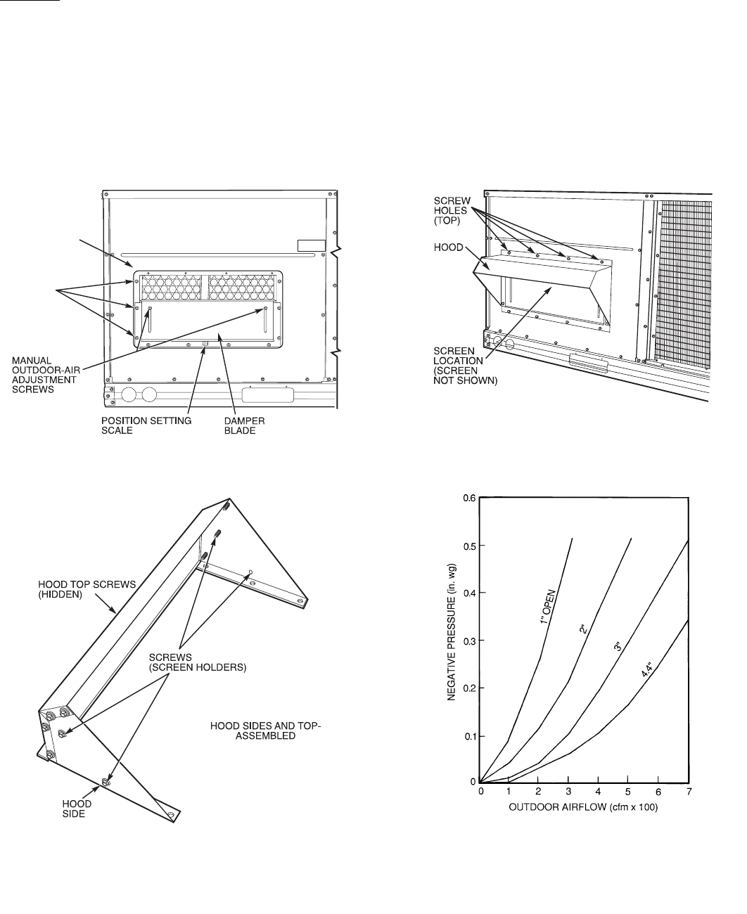
8. Adjust minimum position setting of the damper blade
by adjusting the manual outdoor-air adjustment
screws on the front of the damper blade. See Fig. 12.
Slide blade vertically until it is in the appropriate po-
sition determined by Fig. 15. Tighten screws.
9. Remove and save screws currently on sides of hood.
Insert screen. Secure screen to hood using the screws.
See Fig. 14.
OUTDOOR
AIR OPENING
PANEL
3 SCREWS
(SIDE)
Fig. 12 — Damper Panel withManual Outdoor-Air
Damper Installed
Fig. 13 — Outdoor-Air Hood Details
Fig. 14 — Outdoor-Air Damper with
Hood Attached
Fig. 15 — Outdoor-Air Damper Position Setting
—15—
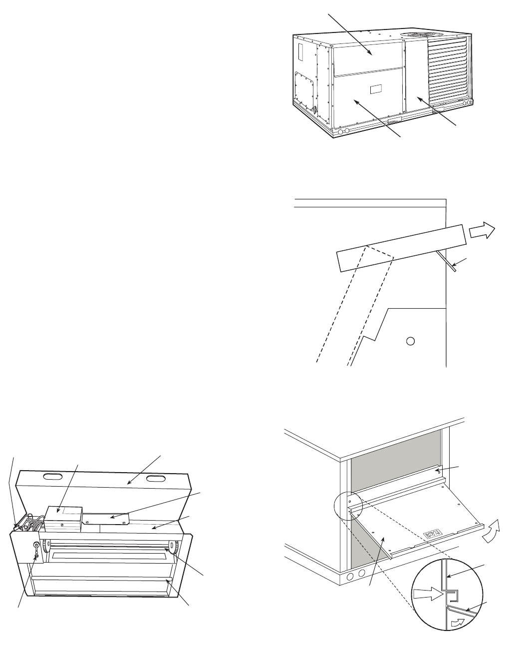
B. Optional EconoMi$er+
See Fig. 16 for EconoMi$er+ component locations.
NOTE: These instructions are for the factory-installed
optional EconoMi$er+ only. Refer to the accessory
EconoMi$er+ installation instructions when field installing
an EconoMi$er+ accessory.
1. To remove the existing unit filter access panel, raise
the panel and swing the bottom outward. The panel is
now disengaged from the track and can be removed.
See Fig. 17.
2. The box with the EconoMi$er+ hood components is
shipped in the compartment behind the
EconoMi$er+. The EconoMi$er+ does not have to be
removed to retrieve the hood box. Remove the screw
holding the hood box bracket to the top of the
EconoMi$er+. Slide the hood box out of the unit. See
Fig. 18.
IMPORTANT: If a power exhaust accessory will be installed
on the unit, the hood shipped with the unit will not be used
and must be discarded. Save the aluminum filter for use in
the power exhaust.
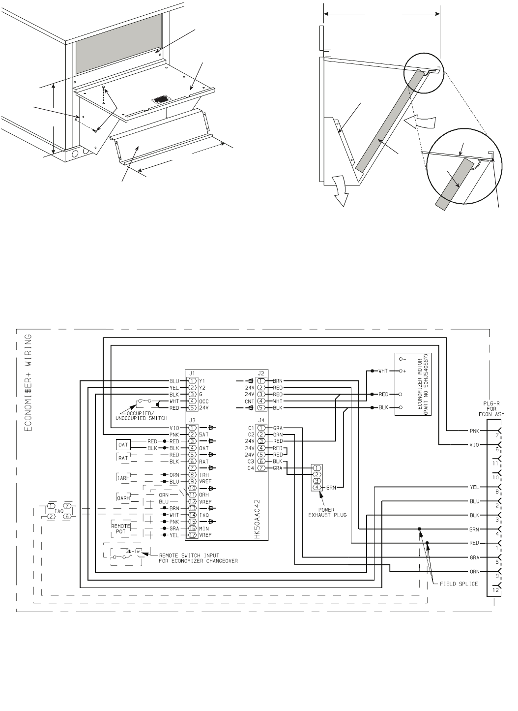
3. The indoor coil access panel will be used as the top of
the hood. Remove the screws along the bottom of the
indoor coil access panel. See Fig. 19.
4. Swing out the indoor coil access panel and insert the
hood sides under the panel (hood top). Use the screws
provided to attach the hood sides to the hood top. Use
the screws provided to attach the hood sides to the
unit. See Fig. 20.
5. Remove the shipping tape holding the EconoMi$er+
barometric relief damper in place.
6. Insert the hood divider between the hood sides. See
Fig. 20. Secure hood divider with 2 screws on each
hood side. The hood divider is also used as the bottom
filter rack for the aluminum filter.
7. Open the filter clips which are located underneath
the hood top. Insert the aluminum filter into the bot-
tom filter rack (hood divider). Push the filter into po-
sition past the open filter clips. Close the filter clips
to lock the filter into place. See Fig. 21.
8. Caulk the ends of the joint between the unit top panel
and the hood top. See Fig. 19.
9. Replace the filter access panel.
10. Install all EconoMi$er+ accessories. EconoMi$er+
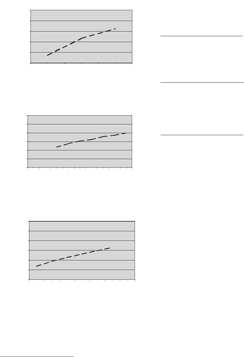
wiring is shown in Fig. 22.
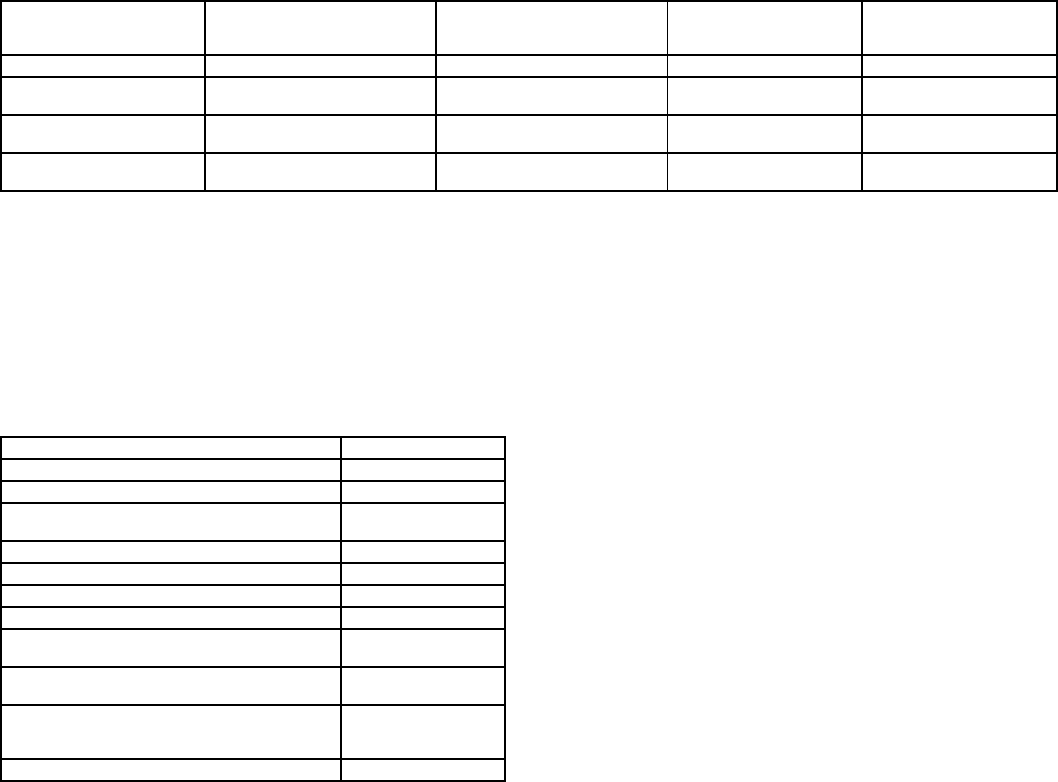
Barometric flow capacity is shown in Fig. 23. Outdoor air
leakage is shown in Fig. 24. Return air pressure drop is
shown in Fig. 25.
FILTER ACCESS PANEL
OUTDOOR-AIR OPENING AND
INDOOR COIL ACCESS PANEL
COMPRESSOR
ACCESS PANEL
HoodBox
HOOD BOX
BRACKET
Fig. 17 — Typical Access Panel Locations
Fig. 18 — Hood Box Removal
Fig. 19 — Indoor Coil Access Panel Relocation
SIDE
PANEL
INDOOR
COIL
ACCESS
PANEL
INDOOR
COIL
ACCESS
PANEL
CAULK
HERE
TOP
SIDE
PANEL
Fig. 16 — EconoMi$er+ Component Locations
ECONOMI$ER+
PLUG
ECONOMI$ER+
CONTROLLER
(UNDER COVER)
OUTDOOR
AIR HOOD
HOOD
SHIPPING
BRACKET
ECONOMI$ER+
CONTROLLER
LABELS
GEAR
DRIVEN
DAMPER
OUTDOOR AIR
TEMPERATURE
SENSOR
BAROMETRIC
RELIEF
DAMPER
—16—
(FIELD-SUPPLIED)
B
TOP
PANEL
INDOOR COIL
ACCESS PANEL
19 1/16”
SCREW
HOOD DIVIDER
LEFT
HOOD
SIDE
33 3/8”
17 1/4”
DIVIDER
BAROMETRIC
RELIEF
CLEANABLE
ALUMINUM
FILTER FILTER
HOOD
FILTER
CLIP
OUTSIDE
AIR
Fig. 21 — Filter Installation
LEGEND
NOTES:
1. Terminals 13-17 are wired to 5-pin plug assembly (P/N CRE+PLUG001A00).
2. Pin numbers are not printed on the controller. They are provided in this book as a reference.
Fig. 22 — EconoMi$er+ Wiring
ECON — Economizer OARH — Outdoor-Air Relative Humidity (Signal) POT — Potentiometer
IAQ—Indoor-Air Quality (4 to 20 mA) OAT — Outdoor-Air Temperature RAT — Return-Air Temperature
IARH — Indoor-Air Relative Humidity (Signal) ORH — Outdoor-Air Relative Humidity (Sensor) SAT — Supply-Air Temperature
IRH — Indoor-Air Relative Humidity (Sensor) PL — Plug
Fig. 20 — Outdoor-Air Hood Construction
—17—
C. EconoMi$er+ Control Mode
Determine the EconoMi$er+ control mode before installing
sensors and accessories. Different sensors are required for
different control modes, and a number of accessories are
available. Refer to Tables 3 and 4.
Outdoor Dry Bulb Changeover
The standard control mode for the EconoMi$er+ is Outdoor
Dry Bulb Changeover. The outdoor air and supply air tem-
perature sensors are also included as standard.
EconoMi$er+ control is based on the outdoor temperature
relative to a set point in the software. If the outdoor air
temperature is above the set point then the EconoMi$er
should be in minimum position. If the outdoor air tempera-
ture is below the set point, the position should be controlled
to maintain the leaving air temperature set point. The set
point range is 45 to 70 F.
Differential Dry Bulb Changeover
The control supports differential dry bulb changeover con-
trol. This requires an accessory return air temperature
sensor CRTEMPSN001A00 installed in the return air-
stream. Refer to the Start-up section for details on how to
configure and enable the control mode. The user can check
the operation of the sensor using the Read function.
Outdoor Air Enthalpy Changeover
The control supports outside air enthalpy changeover con-
trol. This mode requires a factory-supplied outdoor air tem-
perature sensor (OAT) and an accessory outdoor air
humidity sensor (ORH) (part no. CRHUMDSN001B00).
Refer to the Start-Up section for details on how to configure
and enable the control mode. The user can check the opera-
tion of the sensors using the Read function.
Differential Enthalpy Changeover
The control supports differential enthalpy changeover con-
trol. This requires the factory-supplied outside air tempera-
ture sensor, an accessory outdoor air humidity sensor, an
accessory return air temperature sensor, and an accessory
indoor air humidity sensor. Refer to the Start-Up section for
details on how to configure and enable the control mode. The
user can check the operation of the sensors using the Read
function.
D. Damper Movement
When the EconoMi$er+ board receives initial power, it will
take the damper up to 21/2 minutes before it begins to posi-
tion itself. After the initial positioning, subsequent changes
to damper position will take up to 30 seconds to initiate.
Damper movement from full open to full closed (or vice
versa) takes 21/2 minutes.
If the damper is in the process of changing positions (for
example it is trying to open to 100%) and the fan signal is
turned off, the damper will continue to its 100% open posi-
tion before closing.
NOTE: Occupied minimum position can not be set lower than
+1% higher than the value of IAQ minimum economizer
position. Refer to the setup examples on page 42.
E. EconoMi$er+ Controller Wiring
The EconoMi$er+ is supplied from the factory with a supply
air temperature sensor and an outside air temperature sen-
sor. This allows for operation of the EconoMi$er+ with out-
side air dry bulb changeover control. Additional accessories
can be added to allow for different types of change over con-
trol and operation of the EconoMi$er+ and unit.
F. Thermostats
The EconoMi$er+ control works with conventional thermo-
stats that have a Y1 (cool stage 1), Y2 (cool stage 2), W1
(heat stage 1), W2 (heat stage 2), and G (fan). The
EconoMi$er+ control does not support sensor thermostats
like the T56 and T57. Connections are made at the thermo-
stat terminal connection board located in the main control
box.
0
500
1000
1500
2000
2500
0.05 0.15 0.25
STATIC PRESSURE (in. wg)
FLOW IN CUBIC FEET PER MINUTE (cfm)
0
5
10
15
20
25
30
0.13 0.20 0.22 0.25 0.30 0.35 0.40 0.45 0.50
STATIC PRESSURE (in. wg)
FLOW IN CUBIC FEET PER MINUTE (cfm)
0
1000
2000
3000
4000
5000
6000
0.05 0.10 0.15 0.20 0.25 0.30 0.35
STATIC PRESSURE (in. wg)
FLOW IN CUBIC FEET PER MINUTE (cfm)
Fig. 23 — Barometric Flow Capacity
Fig. 24 — Outdoor-Air Damper Leakage
Fig. 25 — Return-Air Pressure Drop
—18—
Table 3 — EconoMi$er+ Sensor Usage
NOTES:
1. CO2Sensors (Optional, 5-Pin sensor wiring plug CRE+PLUG001A00 required for installation.).
33ZCSENCO2 — Room sensor (adjustable). Aspirator box is required for duct mounting of the sensor.
33ZCASPCO2 — Aspirator box used for duct-mounted CO2room sensor.
33ZCT55CO2 — Space temperature and CO2room sensor with override.
33ZCT56CO2 — Space temperature and CO2room sensor with override and set point.
CRCBDIOX002A00 — Return air CO2sensor.
2. All units include the following Standard Sensors:
Outdoor-Air Sensor — set point adjustable from 45 F to 70 F, factory set at 65 F.
Supply-Air Sensor — set point adjustable from 40 F to 65 F. Factory set at 55 F.
All temperature adjustments are made at the EconoMi$er+controller.
Table 4 — EconoMi$er+ Field-Installed Accessories
*5-pin sensor wiring plug accessory (P/N CRE+PLUG001A00) is
required to install IAQ sensor.
G. Outdoor Air Temperature (OAT)Sensor (Provided)
The outdoor air temperature sensor is a 10K thermistor used
to measure the outdoor-air temperature. The sensor controls
EconoMi$er+ changeover and compressor lockout. The sen-
sor is factory-installed on the EconoMi$er+ in the outdoor
airstream. The operating range of temperature measure-
ment is 0° to 158 F. See Tables 5 and 6 for thermistor resis-
tance and resolution values.
The temperature sensor looks like an eyelet terminal with
wires running to it. The sensor is located in the “crimp end”
and is sealed from moisture.
The user can read the value of the sensor using the Read
mode, described in the Start-Up section.
H. Supply Air Temperature (SAT)Sensor (Provided)
The supply air temperature sensor is a 10K thermistor
located at the inlet to the indoor fan. This sensor must be
field installed. The operating range of temperature measure-
ment is 0° to 158 F. See Tables 5 and 6 for thermistor resis-
tance and resolution values.
The temperature sensor looks like an eyelet terminal with
wires running to it. The sensor is located in the “crimp end”
and is sealed from moisture.
The user can read the value of the sensor using the Read
mode, described in the EconoMi$er+ Controller section.
I. Indoor Air Quality (IAQ) Sensor
Any indoor air quality or CO2 sensor that provides a 4 to
20 mA output can be used as the IAQ sensor. The controller
will modulate the outdoor-air damper to provide ventilation
based on the sensor output and the IAQ setting of the con-
troller. The CO2 sensor will modulate the outdoor-air damper
from the minimum position (IAQ minimum damper position
set point) to the maximum position (occupied minimum
damper position). When there is no CO2 call, the damper will
go to the unoccupied minimum position. When there is a CO2
call, the damper will be between the IAQ minimum econo-
mizer set point position and the occupied minimum damper
position.
Mount the sensor according to manufacturer specifications.
In order to wire this sensor, an accessory 5-pin plug (part
number CRE+PLUG001A00) is required. See Fig. 22.
The IAQ sensor is wired to the ground and IAQ wires in the
harness. The accessory 5-pin wiring plug is connected to pins
13-17 of J3 on the EconoMi$er+ controller. Push the plug
down onto the pins of the EconoMi$er+ controller to install.
Pins 13 and 14 are used for the IAQ sensor. Pins 15-17 are
used for the field-installed remote potentiometer. Connect
the IAQ sensor to the BRN and WHT wires of the accessory
5-pin plug.
NOTE: Pin numbers are not shown on the controller. They
are provided only as reference for the installer. On the
EconoMi$er+ board, they numbered 1-17 from left to right,
but only the 1 and the 17 are printed on the board.
Sensor wiring should be extended with wire and wire nuts
and routed to the IAQ sensor location. Adjust the IAQ set-
ting at the controller to correspond to the IAQ voltage output
of the sensor at the user-determined set point. See Fig. 26.
Power the sensor with a field-supplied transformer.
J. Return Air Temperature (RAT)Sensor
The EconoMi$er+ controller will accept input from the
accessory 10K return air temperature sensor
(CRTEMPSN001A00) in addition to the outdoor air tempera-
ture sensor shipped with the EconoMi$er+. By using both
sensors, the outdoor air and the return air temperatures are
compared (differential dry bulb) for optimal energy savings.
See Tables 5 and 6 for thermistor resistance and resolution
values.
The temperature sensor looks like an eyelet terminal with
wires running to it. The sensor is located in the “crimp end”
and is sealed from moisture.
APPLICATION STANDARD OUTDOOR AIR
TEMPERATURE SENSOR
ACCESSORY RETURN AIR
TEMPERATURE SENSOR
ACCESSORY
OUTDOOR AIR
HUMIDITY SENSOR
ACCESSORY INDOOR
RETURN AIR
HUMIDITY SENSOR
Standard Unit Included — HH79NZ039 — — —
Differential
Dry Bulb Included — HH79NZ039 Required —
CRTEMPSN001A00 ——
Outdoor Air
Enthalpy Included — HH79NZ039 — Required —
CRHUMDSN001B00 —
Differential Enthalpy Included — HH79NZ039 Required —
CRTEMPSN001A00
Required —
CRHUMDSN001B00
Required —
CRHUMDSN001B00
DESCRIPTION PART NUMBER
3-6 Ton Power Exhaust 208-230 v 1 PhCRPWREXH030A00
3-6 Ton Power Exhaust 460 v 3 PhCRPWREXH021A00
Return Air Temperature Sensor with
Harness CRTEMPSN001A00
Outdoor Air Humidity Sensor withHarness CRHUMDSN001B00
Indoor Air Humidity Sensor withHarness CRHUMDSN001B00
Return Air CO2Sensor CRCBDIOX002A00*
CO2RoomSensor 33ZCSENCO2*
Aspirator Box for Duct Mount
CO2Sensor 33ZCASPCO2
Space Temperature and CO2
RoomSensor withOverride 33ZCT55CO2*
Space Temperature and CO2
RoomSensor withOverride
and Set Point
33ZCT56CO2*
5-Pin Sensor Wiring Plug CRE+PLUG001A00*
—19—
The user can read the value of the sensor using the Read
mode, described in the EconoMi$er+ Controller section.
Mount the return air temperature sensor on the
EconoMi$er+, through pre-punched holes. See Fig. 27.
The return air temperature (RAT) sensor is provided with a
2-wire, 42-in. long wiring harness with a 2-pin connector. The
plug is installed on pins 5 and 6 on J3 of the EconoMi$er+
controller. The pins are labeled with a ground symbol and
RAT on the EconoMi$er+ controller. See Fig. 22. The red wire
of the harness is connected to pin 5 (ground). The black wire
of the harness is connected to pin 6 (RAT). The wiring har-
ness should be routed from the EconoMi$er+ controller to the
sensor. The controller compares the temperatures of the two
airstreams, chooses the best one, and modulates the
EconoMi$er+ actuator accordingly.
This 10K thermistor is used to measure the return air
temperature vs. resistance curve, per Table 5. The range of
temperature measurement is between 0° and 158 F. See
Table 6 for resolution.
K. Outdoor Air Humidity Sensor
The EconoMi$er+ controller accepts input from the accessory
outdoor air humidity sensor in addition to the outdoor air
temperature sensor shipped with the EconoMi$er+. By using
both sensors, the total enthalpy of the outside air is
calculated.
Mount the outdoor-air humidity sensor in to the
EconoMi$er+, through the pre-punched holes. See Fig. 28.
The outdoor-air humidity sensor is provided with a 2-wire,
42-in. wiring harness with a 2-pin connector. The plug is
installed on pins 11 and 12 on J3 of the EconoMi$er+ con-
troller. The pins are labeled ORH and VREF on the
EconoMi$er+ controller. See Fig. 22. The orange wire of the
harness is connected to pin 11 (ORH). The blue wire of the
harness is connected to pin 12 (VREF). The wiring harness
should be routed from the EconoMi$er+ controller to the sen-
sor location.
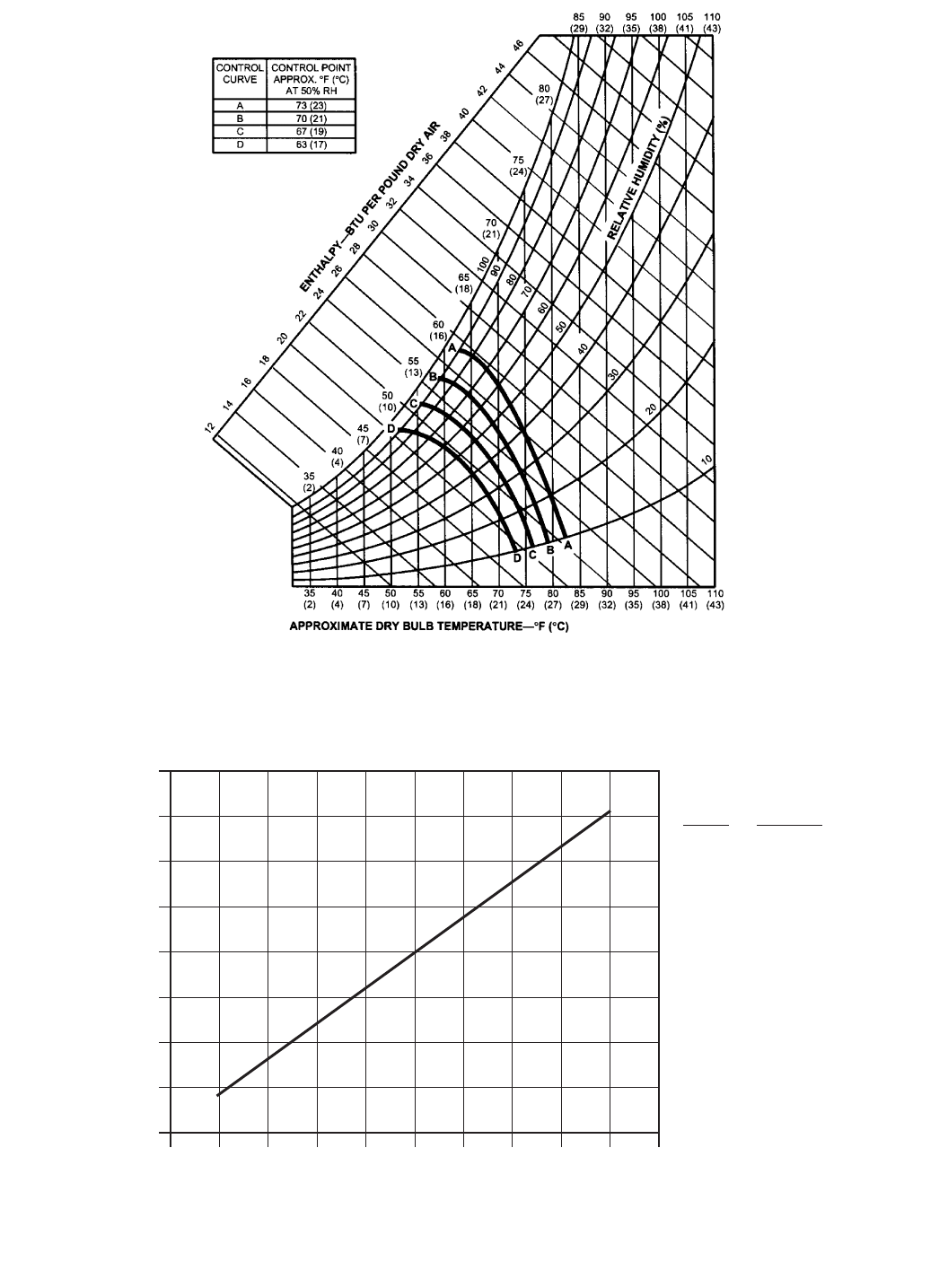
The outdoor enthalpy changeover curve is set at the
EconoMi$er+ controller. The factory default is curve “A.” See
Fig. 29. See Fig. 30 for Sensor Curve vs. Humidity.
ECONOMI$ER+ CONTROLLER
ACTUATOR
RETURN AIR
TEMP SENSOR
(HIDDEN)
HOOD
GROMMET
CURB
VERTICAL ECONOMI$ER+
(3 TO 12 1/2 TON UNITS)
(SIDE VIEW)
INDOOR AIR
HUMIDITY SENSOR
Fig. 27 — Return Air Temperature Sensor
ECONOMI$ER+
WIRING
GROMMET
OUTDOOR AIR
HUMIDITY
SENSOR
OUTDOOR AIR
TEMPERATURE
SENSOR
RELIEF
BLADE
CONTROLLER
ECONOMI$ER+
Fig. 28 — Outdoor-Air Humidity Sensor
0
1000
2000
3000
4000
5000
6000
2345678
800 ppm
900 ppm
1000 ppm
1100 ppm
RANGE CONFIGURATION (ppm)
DAMPER VOLTAGE FOR MAX VENTILATION RATE
CO SENSOR MAX RANGE SETTING
2
Fig. 26 — Indoor Air Quality Voltage Setting
—20—
Table 5 — Outdoor Air, Return Air, and Supply Air Temperature Sensors
(CRTEMPSN001A00 or HH79NZ039)— 10K Thermistor Curve
Table 6 — Outdoor Air, Return Air, and Supply Air
Temperature Sensors (CRTEMPSN001A00 or HH79NZ039)—Thermistor Resolution
TEMPERATURE RESISTANCE TEMPERATURE RESISTANCE TEMPERATURE RESISTANCE
CF ohmsCF ohmsCF ohms
120 248.0 390.0 66 150.8 2,011.0 12 53.6 18,090.0
119 246.2 401.2 65 149.0 2,083.0 11 51.8 18,972.0
118 244.4 412.8 64 147.2 2,157.0 10 50.0 19,903.0
117 242.6 424.8 63 145.4 2,235.0 9 48.2 20,883.0
116 240.8 437.2 62 143.6 2,315.0 8 46.4 21,918.0
115 239.0 450.0 61 141.8 2,400.0 7 44.6 23,013.0
114 237.2 462.5 60 140.0 2,488.0 6 42.8 24,117.0
113 235.4 475.5 59 138.2 2,579.0 5 41.0 25,396.0
112 233.6 488.9 58 136.4 2,675.0 4 39.2 26,686.0
111 231.8 502.7 57 134.6 2,774.0 3 37.4 28,052.0
110 230.0 517.0 56 132.8 2,878.0 2 35.6 29,498.0
109 228.2 531.0 55 131.0 2,986.0 1 33.8 31,030.0
108 226.4 545.6 54 129.2 3,099.0 0 32.0 32,654.0
107 224.6 560.5 53 127.4 3,217.0 –1 30.2 34,367.0
106 222.8 576.0 52 125.6 3,340.0 –2 28.4 36,182.0
105 221.0 592.0 51 123.8 3,469.0 –3 26.6 38,109.0
104 219.2 608.5 50 122.0 3,603.0 –4 24.8 40,153.0
103 217.4 625.5 49 120.2 3,743.0 –5 23.0 42,324.0
102 215.6 643.0 48 118.4 3,889.0 –6 21.2 44,617.0
101 213.8 661.2 47 116.6 4,042.0 –7 19.4 47,052.0
100 212.0 680.0 46 114.8 4,203.0 –8 17.6 49,640.0
99 210.2 700.0 45 113.0 4,370.0 –9 15.8 52,392.0
98 208.4 720.6 44 111.2 4,544.0 –10 14.0 55,319.0
97 206.6 742.0 43 109.4 4,727.0 –11 12.2 58,415.0
96 204.8 764.1 42 107.6 4,918.0 –12 10.4 61,711.0
95 203.0 787.0 41 105.8 5,117.0 –13 8.6 65,219.0
94 201.2 810.8 40 104.0 5,327.0 –14 6.8 68,957.0
93 199.4 835.5 39 102.2 5,546.0 –15 5.0 72,940.0
92 197.6 861.0 38 100.4 5,774.0 –16 3.2 77,162.0
91 195.8 888.5 37 98.6 6,014.0 –17 1.4 81,662.0
90 194.0 915.0 36 96.8 6,266.0 –18 –0.4 86,463.0
89 192.2 944.0 35 95.0 6,530.0 –19 –2.2 91,588.0
88 190.4 974.0 34 93.2 6,806.0 –20 –4.0 97,060.0
87 188.6 1005.0 33 91.4 7,096.0 –21 –5.8 102,868.0
86 186.8 1037.0 32 89.6 7,401.0 –22 –7.6 109,075.0
85 185.0 1070.0 31 87.8 7,720.0 –23 –9.4 115,710.0
84 183.2 1104.0 30 86.0 8,056.0 –24 –11.2 122,807.0
83 181.4 1140.0 29 84.2 8,407.0 –25 –13.0 130,402.0
82 179.6 1177.0 28 82.4 8,776.0 –26 –14.8 138,482.0
81 177.8 1215.0 27 80.6 9,164.0 –27 –16.6 147,134.0
80 176.0 1255.0 26 78.8 9,571.0 –28 –18.4 156,404.0
79 174.2 1297.0 25 77.0 10,000.0 –29 –20.2 166,342.0
78 172.4 1340.0 24 75.2 10,449.0 –30 –22.0 177,000.0
77 170.6 1385.0 23 73.4 10,921.0 –31 –23.8 188,340.0
76 168.8 1431.0 22 71.6 11,418.0 –32 –25.6 200,510.0
75 167.0 1480.0 21 69.8 11,942.0 –33 –27.4 213,570.0
74 165.2 1530.0 20 68.0 12,493.0 –34 –29.2 227,610.0
73 163.4 1582.0 19 66.2 13,071.0 –35 –31.0 242,700.0
72 161.6 1637.0 18 64.4 13,681.0 –36 –32.8 258,730.0
71 159.8 1693.0 17 62.6 14,323.0 –37 –34.6 275,970.0
70 158.0 1752.0 16 60.8 15,000.0 –38 –36.4 294,520.0
69 156.2 1813.0 15 59.0 15,714.0 –39 –38.2 314,490.0
68 154.4 1876.0 14 57.2 16,464.0 –40 –40.0 336,000.0
67 152.6 1943.0 13 55.4 17,255.0
RANGE RESOLUTION
Low High
FF F
–41 –18 4.0
–17 14 2.0
15 28 1.0
29 47 0.8
48 86 0.7
87 108 0.8
109 126 1.0
127 171 2.0
127 195 4.0
—21—
Fig. 29 — Enthalpy Changeover Settings
20
18
16
14
12
10
8
6
4
0102030
40 50 60 70 80 90 100
RH (%) CURRENT
(mA)
10
20
30
40
50
60
70
80
90
5.6
7.2
8.8
10.4
12.0
13.6
15.2
16.8
18.4
HUMIDITY IN % RH
CURRENT IN mA
RH — Relative Humidity Fig. 30 — Humidity Sensor Current vs. Humidity
—22—
L. Indoor Air Humidity Sensor
For differential enthalpy sensing, the EconoMi$er+ control-
ler uses the standard outdoor air temperature sensor, the
outdoor air humidity sensor, and the optional indoor air
humidity sensor, an optional return air temperature sensor
(RAT). The indoor-air humidity sensor is provided with a
2-wire, 42-in. wiring harness with a 2-pin connector. The
plug is installed on pins 8 and 9 on J3 of the EconoMi$er+
controller. The pins are labeled IRH and VREF on the
EconoMi$er+ controller. See Fig. 22. The orange wire of the
harness is connected to pin 8 (IRH). The blue wire of the har-
ness is connected to pin 9 (VREF). The wiring harness
should be extended with wires and wire nuts and routed
from the EconoMi$er+ controller to the sensor location. The
EconoMi$er+ controller compares the outdoor air enthalpy
to the return air enthalpy to determine EconoMi$er+ use.
The controller selects the lower enthalpy air (return or out-
door) for cooling. For example, when the outdoor air has a
lower enthalpy than the return air, the EconoMi$er+ control-
ler opens the damper to bring in outdoor air for free cooling.
Mount the return-air humidity sensor in the return-air duct.
See Fig. 31.
The outdoor enthalpy changeover curve is set with at the
EconoMi$er+ controller. The selectable curves are A, B, C,
and D. The factory default is curve “A.” See Fig. 29. See
Fig. 30 for Sensor Curve vs. Humidity.
M. Occupied/Unoccupied Switch
The EconoMi$er+ supports the use of a field-supplied
occupied/unoccupied switch. When the switch is closed it pro-
vides a 24-vac signal to the unit for occupied mode and when
open, there is no signal to indicate unoccupied mode. The
control can be configured to allow different minimum econo-
mizer damper positions and to control how mechanical cool-
ing will and will not be used in the occupied mode.
NOTE: The remote potentiometer (see below) will override
the occupied minimum position if the potentiometer setting
is greater than the occupied minimum position.
A wire from J1-OCC (pin 4) and a wire from J1-24V (pin 5)
are wire-nutted together to jumper the terminals.
An occupied/unoccupied switch can be field-installed in place
of the jumper to allow the user to force the control into
occupied or unoccupied mode of operation for EconoMi$er+
damper position. The occupied/unoccupied switch is required
if the user wants to use unoccupied free cooling or different
EconoMi$er+ damper vent positions in the unoccupied mode.
N. Power Exhaust
Refer to the Accessory Power Exhaust installation instruc-
tions for information on installing the power exhaust
accessory.
O. Remote EconoMi$er+ Enable Control
When the control is used with energy management systems
that enable and disable the EconoMi$er+, the user can
install a field-supplied enable/disable switch. The switch
must be wired in series with a 3K ohm, 1 watt or greater
resistor. The switch is wired to terminals ORH (pin 11) and
VREF (pin 12) on J3. Refer to the Start-Up section for details
on how to configure the control.
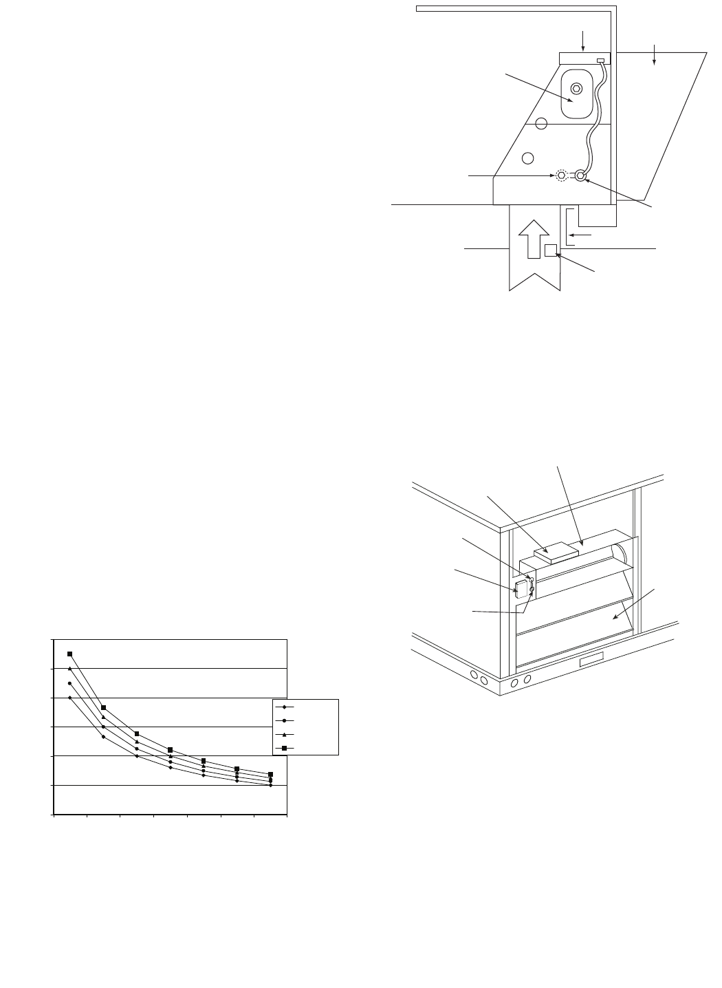
P. R e mote Potentiometer Occupied MinimumPosition
The occupied minimum position set point remote potentiom-
eter (field-supplied) is used when requiring additional tem-
porary ventilation. The remote potentiometer (10K ohm -
closed damper, 100K ohm - open damper) will only control
the occupied minimum position.
The accessory 5-in wiring plug, CRE+PLUG001A00 is
required to connect the potentiometer.
The plug is installed on pins 15, 16 and 17 on J3 of the
EconoMi$er+ controller. The pins are labeled with the
ground symbol, MIN and VREF on the EconoMi$er+ control-
ler. See Fig. 22. The pink wire from the harness is connected
to pin 15 (ground symbol). The gray wire from the harness is
connected to pin 16 (MIN). The yellow wire from the harness
is connected to pin 16 (VREF). The wiring harness should
be extended with wires and wire nuts and routed from the
EconoMi$er+ controller to the remote potentiometer
location.
NOTE: Pins 13 (ground symbol) and 14 (IAQ), which are
wired to the accessory 5-pin plug, are not used for the remote
potentiometer installation. They are used for an accessory
IAQ sensor (if required).
The unoccupied minimum position can only be set at the
controller. The occupied minimum position set point config-
ured at the EconoMi$er+ controller should be set to 0 when
using a remote potentiometer. The occupied minimum posi-
tion will also be used as part of the IAQ routing; it will be the
maximum position the damper moves to when there is an
IAQ call.
If the remote potentiometer (occupied) position is greater
than the EconoMi$er+ controller unoccupied minimum posi-
tion, then the remote potentiometer setting will be used. The
remote potentiometer is field supplied and must be a 3-wire,
linear potentiometer with a resistance between 10K ohm
and 100K ohm (such as the Honeywell S963B1128).
Q.Demand Ventilation Control
Demand ventilation control uses an IAQ sensor
(CRE+PLUG001A00 required) to control the amount of out-
side air admitted into the system. Normally, the minimum
position of the EconoMi$er+ damper is established based on
the demand occupancy of the space. The IAQ sensor will be
used to modulate the EconoMi$er+ minimum damper position
below the normal minimum position based on full occupancy.
The lower limit is called the base ventilation rate. See Fig. 32.
If there is no IAQ signal the damper will be in the unoccu-
pied minimum position (configuration item number 3). If
there is an IAQ signal the damper will be in the occupied
ECONOMI$ER+
ECONOMI$ER+
CONTROLLER
GROMMET
RETURN AIR
HUMIDITY SENSOR
RETURN DUCT
(FIELD-PROVIDED)
Fig. 31 — Return Air Humidity Sensor
—23—
minimum position (configuration item number 15), unless
the remote potentiometer is used to override it.
For the demand ventilation control logic, the user configures
the lower and upper actuator position to establish the base
ventilation rate (IAQMIN_SP) and the design ventilation
rate (ECONOMIN_SP) for full occupancy. When the
EconoMi$er+ damper is being modulated for demand venti-
lation control, the damper position will be between
IAQMIN_SP and ECONOMIN_SP. The upper IAQ differen-
tial set point is DAQHI. The lower IAQ differential set point
is DAQLO.
The differential set points represent the differential CO2
level (in ppm) above the outdoor reference IAQ levels.
Normally, the outdoor reference IAQ levels are around
400 ppm, but the value should be configured based on the
reference levels taken at the job site.
The following equation is used to determine EconoMi$er+
damper position (ECONOMIN_POS):
R. CO
2
Sensor Configuration
The CO2 sensor has preset standard voltage settings that
can be selected anytime after the sensor is powered up. See
Table 7.
1. Press Clear and Mode buttons. Hold at least 5 sec-
onds until the sensor enters the Edit mode.
2. Press Mode 2 times. The STDSET Menu will appear.
3. Use the Up/Down button to select the preset number.
See Table 7.
4. Press Enter to lock in the selection.
Press Mode to exit and resume normal operation. The cus-
tom settings of the CO2 sensor can be changed any time
after the sensor is energized. Follow the steps below to
change the non-standard settings:
1. Press Clear and Mode buttons. Hold at least 5 sec-
onds until the sensor enters the Edit mode.
2. Press Mode 2 times. The STDSET Menu will appear.
3. Use the Up/Down button to toggle to the NONSTD
menu and press Enter.
4. Use the Up/Down button to toggle through each of
the nine variables, starting with Altitude, until the
desired setting is reached.
5. Press Mode to move through the variables.
6. Press Enter to lock in the selection, then press Mode
to continue to the next variable.
S. Dehumidification of FreshAir withDemand Control Ven-
tilation (DCV)
Information from ASHRAE (American Society of Heating,
Refrigeration and Air Conditioning Engineers) indicates that
the largest humidity load on any zone is the fresh air intro-
duced. For some applications, a device such as a energy
recovery unit is added to reduce the moisture content of the
fresh air being brought into the building when the enthalpy
is high. In most cases, the normal heating and cooling pro-
cesses are more than adequate to remove the humidity loads
for most commercial applications.
This makes the control of the dehumidification device simple
when using the enthalpy or differential enthalpy sensor. The
enthalpy sensor or differential enthalpy sensor is installed
on the equipment to determine economizer operation. The
high enthalpy signal from the temperature and humidity
sensors or differential temperature and humidity sensors
can be used to turn on the outdoor air moisture removal
device any time fresh air is required for the space.
The energy recovery device should be sized for maximum
latent and sensible conditioning at maximum ventilation on
a design day.
A calculation for leaving-air temperature on a low ambient,
low ventilation day should also be done to determine the
supply-air temperature of the return and pre-conditioned
outside air. The design should produce air temperature
somewhat near room conditions to prevent reheat of the air
mixture. The energy recovery device should be interlocked
with the heat to turn off the device when in the heat mode.
Table 7 — CO2Sensor*Standard Settings
LEGEND
*Available sensor part numbers are listed in Table 4.
IAQMIN_SP += (ECONOMIN_SP – IAQMIN_SP) * (IAQ – OAQ – DAQLO)
(DAQHI – DAQLO)
SETTING EQUIPMENT OUTPUT
VENTILATION
RATE
(cfm/Person)
ANALOG
OUTPUT
CO2CONTROL
RANGE (ppm)
OPTIONAL
RELAY SETPOINT
(ppm)
RELAY
HYSTERESIS
(ppm)
1Interface with Standard
Building Control System
Proportional Any 4-20 mA 0-2000 1000 50
2Proportional Any 7-20 mA 0-2000 1000 50
3Exponential Any 4-20 mA 0-2000 1100 50
4
Economizer
Proportional 15 4-20 mA 0-1100 1100 50
5Proportional 20 4-20 mA 0- 900 900 50
6Exponential 15 4-20 mA 0-1100 1100 50
7Exponential 20 4-20 mA 0- 900 900 50
8Health &Safety Proportional — 4-20 mA 0-9999 5000 500
9Parking/Air Intakes/ Loading Docks Proportional — 4-20 mA 0-2000 700 50
ppm—Parts Per Million
100
500 700
1100
INSIDE/OUTSIDE CO
2
DIFFERENTIAL
INSIDE CO
2
CONCENTRATION
AQ
DIFFERENTIAL
LOW (DAQLO)
AQ
DIFFERENTIAL
HIGH (DAQHI)
IAQ
MINIMUM
ECONOMIZER
POSITION
SET POINT
(IAQMIN_SP)
ECONOMIZER
MINIMUM
OCCUPIED
DAMPER
POSITION
(ECONOMIN_SP)
VENTILATION FOR PEOPLE
VENTILATION FOR SOURCES
FULL OCCUPANCY
VENTILATION RATE
DAMPER
POSTION
CO LEVEL
2
OUTDOOR REFERENCE
LEVEL (OAQ)= 400
Fig. 32 — Demand Ventilation Control
—24—
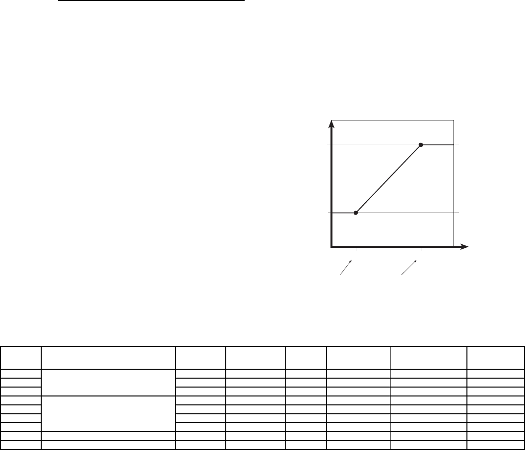
IX. STEP 9 — ADJUST EVAPORATOR-FAN SPEED
Adjust evaporator-fan rpm to meet jobsite conditions. Table 8
shows fan rpm at motor pulley settings. Table 9 shows motor
performance. Refer to Tables 10-33 to determine fan speed
settings.
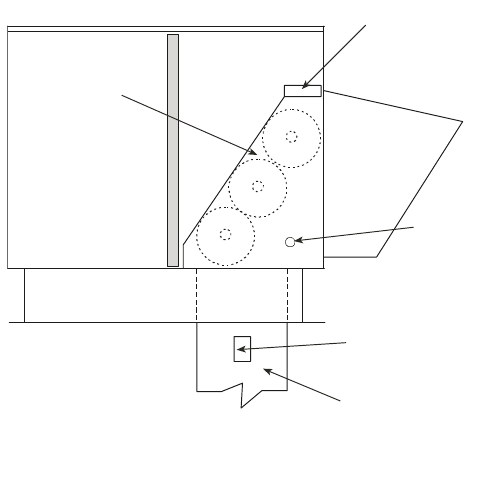
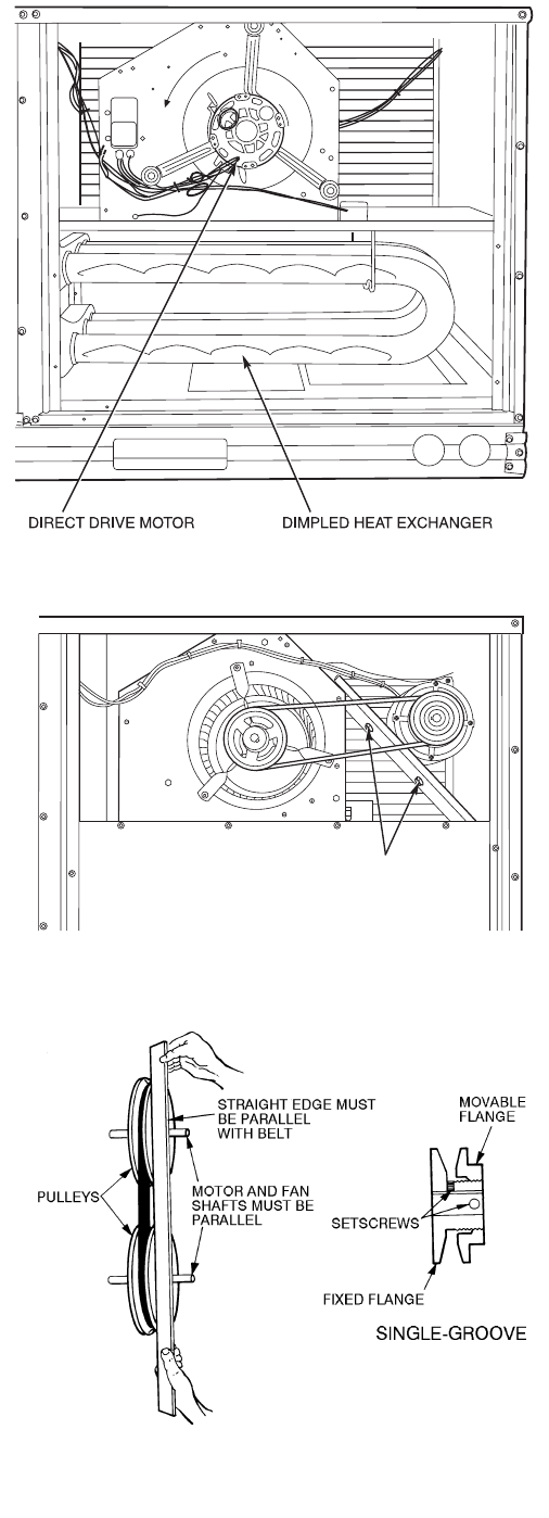
A. Direct-Drive Motors
The evaporator-fan motor factory speed setting is shown on
label diagram affixed to base unit. If other than factory set-
ting is desired, refer to label diagram for motor reconnection.
See Fig. 33 for direct drive motor location.
B. Belt-Drive Motors
Fan motor pulleys are factory set for speed shown in Table 1.
See Fig. 34 for belt drive motor location.
NOTE: Before adjusting fan speed, make sure the new fan
speed will provide an air temperature rise range as shown in
Table 1.
To change fan speed:
1. Shut off unit power supply and tag disconnect.
2. Loosen belt by loosening fan motor mounting nuts.
See Fig. 34.
3. Loosen movable pulley flange setscrew (see Fig. 35).
4. Screw movable flange toward fixed flange to increase
speed and away from fixed flange to decrease speed.
Increasing fan speed increases load on motor. Do not
exceed maximum speed specified in Table 1.
5. Set movable flange at nearest keyway of pulley hub
and tighten setscrew. (See Table 1 for speed change
for each full turn of pulley flange.)
To align fan and motor pulleys:
1. Loosen fan pulley setscrews.
2. Slide fan pulley along fan shaft.
3. Make angular alignment by loosening motor from
mounting.
To adjust belt tension:
1. Loosen fan motor mounting nuts.
2. Slide motor mounting plate away from fan scroll for
proper belt tension (1/2-in. deflection with 8 to 10 lb of
force).
3. Tighten motor mounting nuts.
4. Adjust bolt and tighten nut to secure motor in fixed
position.
Fig. 33 — Direct-Drive Motor Mounting
MOTOR MOUNTING
PLATE NUTS
Fig. 34 — Belt Drive Motor Mounting
Fig. 35 — Evaporator-Fan Pulley Adjustment
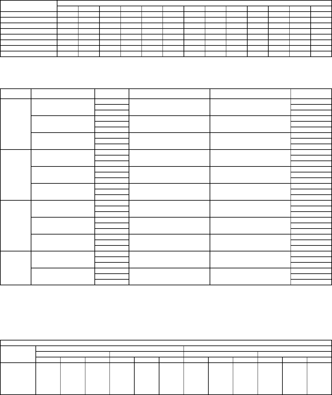
—25—
Table 8 — Fan Rpmat Motor Pulley Settings*
*Approximate fan rpm shown.
†Indicates alternate motor and drive package.
**Indicates high-static motor and drive package.
††Indicates standard motor and drive package.
Table 9 — Motor Data
LEGEND
BHP — Brake Horsepower
*Extensive motor and electrical testing on these units ensures that the full horse-
power range of the motors can be utilized with confidence. Using your fan
motors up to the horsepower ratings shown in this table will not result in nui-
sance tripping or premature motor failure. Unit warranty will not be affected.
†Single phase/three-phase.
NOTES:
1. All indoor-fan motors 5 hp and larger meet the minimum efficiency require-
ments as established by the Energy Policy Act of 1992 (EPACT) effective
October 24, 1997.
2. High-static motor not available on single-phase units.
Table10—FanPerformance 580F036 — Vertical Discharge Units, Standard Motor
LEGEND See page 36 for general fan performance notes.
UNIT
580F
MOTOR PULLEY TURNS OPEN
01/211
1/222
1/233
1/244
1/255
1/26
036† 1045 1009 973 937 901 865 829 793 757 721 685 — —
036** 1455 1423 1392 1360 1328 1297 1265 1233 1202 1170 1138 1107 1075
048† 1175 1135 1094 1054 1013 973 932 892 851 811 770 — —
048** 1455 1423 1392 1360 1328 1297 1265 1233 1202 1170 1138 1107 1075
060† 1192 1166 1140 1114 1087 1061 1035 1009 983 957 930 904 878
060** 1685 1647 1608 1570 1531 1493 1454 1416 1377 1339 1300 — —
072, 073†† 1460 1421 1382 1343 1304 1265 1226 1187 1148 1109 1070 — —
072, 073** 1685 1647 1608 1570 1531 1493 1454 1416 1377 1339 1300 — —
UNIT
580F
EVAPORATOR-FAN
MOTOR
UNIT
VOLTAGE
MAXIMUM ACCEPTABLE
CONTINUOUS BHP*
MAXIMUM ACCEPTABLE
OPERATING WATTS
MAXIMUM
AMP DRAW
036
Standard
208/230
0.34 440
2.8
460 1.3
575 1.3
Alternate
208/230
1.20 1000
4.9
460 2.1
575 2.1
High Static
208/230
2.40 2120
6.0
460 3.0
575 3.0
048
Standard
208/230
0.75 850
3.5
460 1.8
575 1.8
Alternate
208/230
1.20 1000
4.9
460 2.1
575 2.1
High Static
208/230
2.40 2120
6.0
460 3.0
575 3.0
060
Standard
208/230
1.20 1340
5.9
460 3.2
575 3.2
Alternate
208/230
1.30/2.40† 2120
10.1/6.7†
460 3.0
575 3.0
High Static
208/230
2.90 2562
8.6
460 3.9
575 3.9
072, 073
Standard
208/230
2.40 2120
6.7
460 3.0
575 3.0
High Static
208/230
2.90 2562
8.6
460 3.9
575 3.9
STANDARD MOTOR (DIRECT DRIVE)
Airflow
(Cfm)
Low Speed HighSpeed
208 V 230, 460, 575 V 208 V 230, 460, 575 V
ESP Bhp Watts ESP BhpWattsESP Bhp Watts ESP BhpWatts
900 0.49 0.21 253 0.50 0.23 277 0.51 0.26 307 0.55 0.31 363
1000 0.42 0.23 270 0.43 0.25 292 0.43 0.27 321 0.51 0.32 374
1100 0.37 0.24 287 0.38 0.26 307 0.39 0.28 335 0.46 0.33 385
1200 0.33 0.26 304 0.33 0.27 323 0.34 0.29 349 0.40 0.34 397
1300 0.27 0.27 321 0.28 0.29 338 0.28 0.31 364 0.34 0.34 408
1400 0.20 0.29 338 0.23 0.30 354 0.25 0.32 378 — — —
1500 0.16 0.30 355 0.18 0.31 369 0.20 0.33 392 — — —
Bhp—Brake Horsepower Input to Fan
ESP — External Static Pressure (in. wg)
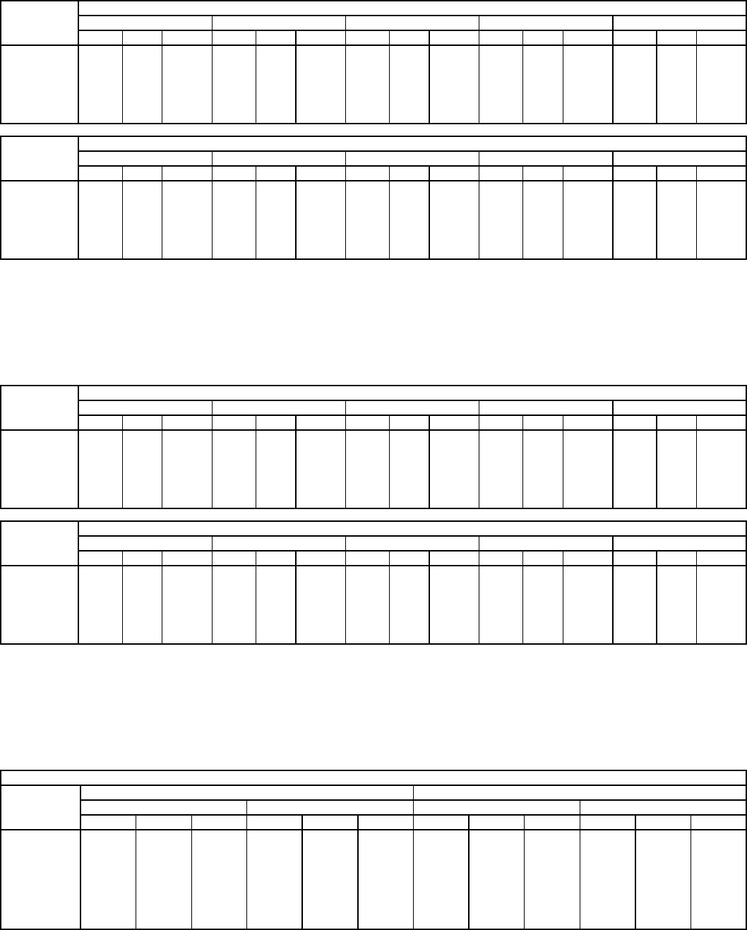
—26—
Table11—FanPerformance 580F036 — Vertical Discharge Units, Alternate Motor (Belt Drive)*
LEGEND
*Motor drive range: 685 to 1045 rpm. All other rpms require a field-
supplied drive.
NOTES:
1. Boldface indicates field-supplied drive is required.
2. Maximum continuous bhp is 1.20.
3. See page 36 for general fan performance notes.
Table12—FanPerformance 580F036 — Vertical Discharge Units, High-Static Motor (Belt Drive)*
LEGEND
*Motor drive range: 1075 to 1455 rpm. All other rpms require a field-supplied
drive.
NOTES:
1. Boldface indicates field-supplied drive is required.
2. Maximum continuous bhp is 2.40.
3. Seee page 36 for general fan performance notes.
Table13—FanPerformance 580F048 — Vertical Discharge Units, Standard Motor
LEGEND See page 36 for general fan performance notes.
AIRFLOW
(Cfm)
EXTERNAL STATIC PRESSURE (in. wg)
0.2 0.4 0.6 0.8 1.0
RpmBhp Watts RpmBhpWattsRpmBhpWattsRpmBhp Watts RpmBhp Watts
900 643 0.15 152 768 0.22 222 870 0.30 296 958 0.37 373 1037 0.46 454
1000 683 0.19 191 804 0.27 268 904 0.35 348 991 0.43 430 1069 0.52 517
1100 725 0.24 237 842 0.32 321 939 0.41 407 1025 0.50 496 1102 0.59 588
1200 767 0.29 291 880 0.38 382 976 0.48 474 1060 0.57 570 1136 0.67 668
1300 811 0.35 352 920 0.45 451 1013 0.55 550 1095 0.66 652 1170 0.76 756
1400 855 0.43 423 960 0.53 529 1051 0.64 636 1132 0.75 744 1205 0.86 855
1500 900 0.51 504 1002 0.62 617 1090 0.74 731 1169 0.85 846 1242 0.97 963
AIRFLOW
(Cfm)
EXTERNAL STATIC PRESSURE (in. wg)
1.2 1.4 1.6 1.8 2.0
RpmBhp Watts RpmBhp Watts RpmBhpWattsRpmBhp Watts RpmBhp Watts
900 1110 0.54 538 1177 0.63 627 1239 0.72 718 1298 0.82 813 1355 0.92 911
1000 1141 0.61 607 1207 0.70 700 1269 0.80 796 1328 0.90 895 1384 1.00 998
1100 1173 0.69 683 1238 0.79 781 1300 0.89 883 1358 0.99 987 1414 1.10 1094
1200 1205 0.77 768 1270 0.88 872 1332 0.98 979 1389 1.09 1088 —— —
1300 1239 0.87 863 1303 0.98 972 1364 1.09 1084 —— — —— —
1400 1273 0.97 967 1337 1.09 1082 —— — —— — —— —
1500 1309 1.09 1082 —— — —— — —— — —— —
Bhp—Brake Horsepower Input to Fan
Watts — Input Watts to Motor
AIRFLOW
(Cfm)
EXTERNAL STATIC PRESSURE (in. wg)
0.2 0.4 0.6 0.8 1.0
RpmBhp Watts RpmBhpWattsRpmBhpWattsRpmBhp Watts RpmBhp Watts
900 643 0.15 152 768 0.22 222 870 0.30 296 958 0.37 373 1037 0.46 454
1000 683 0.19 191 804 0.27 268 904 0.35 348 991 0.43 430 1069 0.52 517
1100 725 0.24 237 842 0.32 321 939 0.41 407 1025 0.50 496 1102 0.59 588
1200 767 0.29 291 880 0.38 382 976 0.48 474 1060 0.57 570 1136 0.67 668
1300 811 0.35 352 920 0.45 451 1013 0.55 550 1095 0.66 652 1170 0.76 756
1400 855 0.43 423 960 0.53 529 1051 0.64 636 1132 0.75 744 1205 0.86 855
1500 900 0.51 504 1002 0.62 617 1090 0.74 731 1169 0.85 846 1242 0.97 963
AIRFLOW
(Cfm)
EXTERNAL STATIC PRESSURE (in. wg)
1.2 1.4 1.6 1.8 2.0
RpmBhp Watts RpmBhpWattsRpmBhpWattsRpmBhp Watts RpmBhp Watts
900 1110 0.54 538 1177 0.63 627 1239 0.72 718 1298 0.82 813 1355 0.92 911
1000 1141 0.61 607 1207 0.70 700 1269 0.80 796 1328 0.90 895 1384 1.00 998
1100 1173 0.69 683 1238 0.79 781 1300 0.89 883 1358 0.99 987 1414 1.10 1094
1200 1205 0.77 768 1270 0.88 872 1332 0.98 979 1389 1.09 1088 1444 1.21 1200
1300 1239 0.87 863 1303 0.98 972 1364 1.09 1084 1421 1.21 1199 1475 1.32 1316
1400 1273 0.97 967 1337 1.09 1082 1397 1.21 1200 1453 1.33 1320 1507 1.45 1443
1500 1309 1.09 1082 1371 1.21 1204 1430 1.33 1327 1486 1.46 1453 1540 1.59 1581
Bhp—Brake Horsepower Input to Fan
Watts — Input Watts to Motor
STANDARD MOTOR (DIRECT DRIVE)
Airflow
(Cfm)
Low Speed HighSpeed
208 V 230, 460, 575 V 208 V 230, 460, 575 V
ESP BhpWattsESP Bhp Watts ESP Bhp Watts ESP BhpWatts
1200 0.68 0.41 458 0.74 0.45 506 0.74 0.51 572 0.85 0.56 632
1300 0.61 0.42 471 0.67 0.46 521 0.66 0.52 589 0.78 0.58 651
1400 0.53 0.45 503 0.59 0.49 556 0.59 0.54 616 0.70 0.60 681
1500 0.45 0.47 536 0.51 0.52 593 0.52 0.56 631 0.63 0.62 698
1600 0.36 0.49 557 0.42 0.54 616 0.45 0.58 654 0.56 0.64 723
1700 0.26 0.52 584 0.32 0.57 646 0.37 0.60 678 0.48 0.66 750
1800 0.15 0.54 610 0.22 0.60 674 0.30 0.62 698 0.41 0.68 772
1900 0.04 0.56 629 0.11 0.62 696 0.23 0.64 720 0.34 0.70 796
2000 — — — — — — 0.16 0.66 744 0.26 0.73 823
Bhp—Brake Horsepower Input to Fan
ESP — External Static Pressure (in. wg)
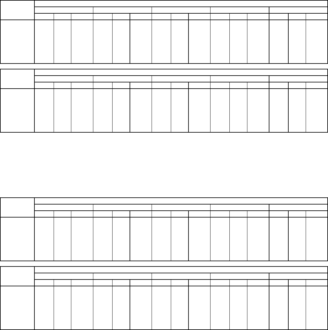
—27—
Table14—FanPerformance 580F048 — Vertical Discharge Units, Alternate Motor (Belt Drive)*
LEGEND
*Motor drive range: 770 to 1175 rpm. All other rpms require a field-
supplied drive.
NOTES:
1. Boldface indicates field-supplied drive is required.
2. Maximum continuous bhp is 1.20.
3. See page 36 for general fan performance notes.
Table15—FanPerformance 580F048 — Vertical Discharge Units, High-Static Motor (Belt Drive)*
LEGEND
*Motor drive range: 1075 to 1455 rpm. All other rpms require a field-supplied
drive.
NOTES:
1. Boldface indicates field-supplied drive is required.
2. Maximum continuous bhp is 2.40.
3. See page 36 for general fan performance notes.
AIRFLOW
(Cfm)
EXTERNAL STATIC PRESSURE (in. wg)
0.2 0.4 0.6 0.8 1.0
RpmBhp Watts RpmBhpWattsRpmBhpWattsRpmBhp Watts RpmBhp Watts
1200 666 0.26 257 778 0.37 367 871 0.47 471 952 0.57 572 1025 0.67 670
1300 701 0.31 306 810 0.43 426 901 0.54 540 981 0.65 651 1053 0.76 760
1400 737 0.36 361 842 0.49 491 931 0.62 616 1010 0.74 738 1081 0.86 856
1500 773 0.42 422 875 0.57 564 963 0.70 699 1040 0.84 831 1110 0.96 960
1600 810 0.49 491 909 0.65 643 994 0.79 790 1070 0.94 932 1140 1.08 1070
1700 847 0.57 567 943 0.73 730 1027 0.89 888 1101 1.05 1040 1170 1.20 1189
1800 885 0.66 652 978 0.83 826 1060 1.00 994 1133 1.16 1157 — — —
1900 923 0.75 745 1014 0.94 930 1093 1.11 1109 — — — — — —
2000 962 0.85 847 1049 1.05 1043 — — — — — — — — —
AIRFLOW
(Cfm)
EXTERNAL STATIC PRESSURE (in. wg)
1.2 1.4 1.6 1.8 2.0
RpmBhp Watts RpmBhpWattsRpmBhpWattsRpmBhp Watts RpmBhp Watts
1200 1093 0.77 767 1155 0.87 861 1213 0.96 955 1268 1.05 1047 1321 1.14 1137
1300 1119 0.87 866 1181 0.98 970 1239 1.08 1073 1294 1.18 1175 —— —
1400 1147 0.98 972 1208 1.09 1086 —— — —— — —— —
1500 1175 1.09 1086 — — — — — — — — — — — —
1600 ——— ——— ——— ——— ———
1700 ——— ——— ——— ——— ———
1800 ——— ——— ——— ——— ———
1900 ——— ——— ——— ——— ———
2000 ——— ——— ——— ——— ———
Bhp—Brake Horsepower Input to Fan
Watts — Input Watts to Motor
AIRFLOW
(Cfm)
EXTERNAL STATIC PRESSURE (in. wg)
0.2 0.4 0.6 0.8 1.0
RpmBhp Watts RpmBhpWattsRpmBhpWattsRpmBhp Watts RpmBhp Watts
1200 666 0.26 257 778 0.37 367 871 0.47 471 952 0.57 572 1025 0.67 670
1300 701 0.31 306 810 0.43 426 901 0.54 540 981 0.65 651 1053 0.76 760
1400 737 0.36 361 842 0.49 491 931 0.62 616 1010 0.74 738 1081 0.86 856
1500 773 0.42 422 875 0.57 564 963 0.70 699 1040 0.84 831 1110 0.96 960
1600 810 0.49 491 909 0.65 643 994 0.79 790 1070 0.94 932 1140 1.08 1070
1700 847 0.57 567 943 0.73 730 1027 0.89 888 1101 1.05 1040 1170 1.20 1189
1800 885 0.66 652 978 0.83 826 1060 1.00 994 1133 1.16 1157 1200 1.32 1316
1900 923 0.75 745 1014 0.94 930 1093 1.11 1109 1165 1.29 1283 1231 1.46 1453
2000 962 0.85 847 1049 1.05 1043 1127 1.24 1233 1198 1.42 1417 1263 1.61 1598
AIRFLOW
(Cfm)
EXTERNAL STATIC PRESSURE (in. wg)
1.2 1.4 1.6 1.8 2.0
RpmBhp Watts RpmBhpWattsRpmBhpWattsRpmBhp Watts RpmBhp Watts
1200 1093 0.77 767 1155 0.87 861 1213 0.96 955 1268 1.05 1047 1321 1.14 1137
1300 1119 0.87 866 1181 0.98 970 1239 1.08 1073 1294 1.18 1175 1346 1.28 1275
1400 1147 0.98 972 1208 1.09 1086 1265 1.21 1199 1320 1.32 1310 1371 1.43 1419
1500 1175 1.09 1086 1235 1.22 1209 1292 1.34 1332 1346 1.46 1452 1397 1.58 1572
1600 1204 1.21 1207 1263 1.35 1340 1320 1.48 1472 1373 1.61 1603 1424 1.74 1732
1700 1233 1.34 1336 1292 1.49 1480 1348 1.63 1622 1401 1.77 1762 1451 1.91 1901
1800 1262 1.48 1473 1321 1.64 1627 1376 1.79 1779 1428 1.94 1930 1479 2.09 2078
1900 1293 1.63 1620 1350 1.79 1784 1405 1.96 1946 1457 2.12 2106 1506 2.28 2265
2000 1323 1.79 1776 1380 1.96 1950 1434 2.13 2123 1486 2.31 2293 —— —
Bhp—Brake Horsepower Input to Fan
Watts — Input Watts to Motor
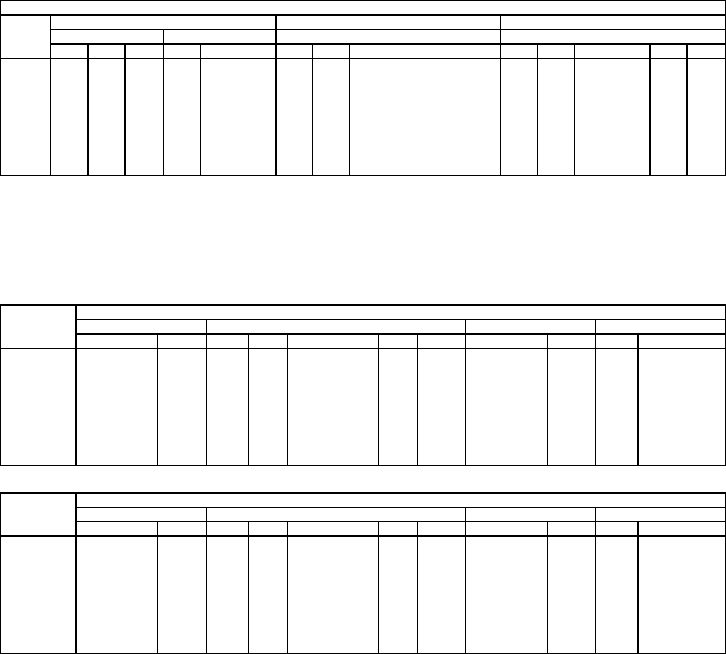
—28—
Table16—FanPerformance 580F060 — Vertical Discharge Units, Standard Motor
LEGEND See page 36 for general fan performance notes.
Table 17 — Fan Performance 580F060 — Single-Phase, Vertical Discharge Unit,
Alternate Motor (Belt Drive)*
LEGEND
*Motor drive range: 878 to 1192 rpm. All other rpms require a field-
supplied drive.
NOTES:
1. Boldface indicates field-supplied drive is required.
2. Maximum continuous bhp is 1.30.
3. See page 36 for general fan performance notes.
STANDARD MOTOR (DIRECT DRIVE)
Airflow
(Cfm)
Low Speed MediumSpeed HighSpeed
208 V 230,460,575 V 208 V 230,460,575 V 208 V 230,460,575 V
ESP Bhp Watts ESP Bhp Watts ESP Bhp Watts ESP Bhp Watts ESP BhpWattsESP Bhp Watts
1500 0.69 0.67 750 1.01 0.71 791 1.00 0.70 782 1.20 0.76 845 1.22 0.79 875 1.28 0.85 949
1600 0.49 0.70 780 0.85 0.74 824 0.85 0.74 821 1.06 0.79 883 1.09 0.82 913 1.17 0.89 988
1700 0.29 0.73 810 0.70 0.77 857 0.70 0.77 861 0.93 0.83 921 0.97 0.85 950 1.06 0.92 1027
1800 0.09 0.75 839 0.54 0.80 891 0.55 0.81 900 0.80 0.86 959 0.84 0.89 988 0.95 0.96 1066
1900 — — — 0.39 0.83 924 0.40 0.84 940 0.67 0.90 997 0.72 0.92 1025 0.84 0.99 1105
2000 — — — 0.23 0.86 957 0.25 0.88 979 0.54 0.93 1035 0.59 0.95 1063 0.73 1.03 1144
2100 — — — 0.08 0.89 990 0.10 0.91 1018 0.41 0.96 1073 0.46 0.99 1101 0.62 1.06 1183
2200 — — — — — — — — — 0.28 1.00 1111 0.34 1.02 1138 0.51 1.10 1222
2300 — — — — — — — — — 0.15 1.03 1149 0.21 1.06 1176 0.40 1.13 1261
2400 — — — — — — — — — 0.02 1.07 1187 0.09 1.09 1213 0.29 1.17 1300
2500 — — — — — — — — — — — — — — — 0.18 1.20 1340
Bhp—Brake Horsepower Input to Fan
ESP — External Static Pressure (in. wg)
AIRFLOW
(Cfm)
EXTERNAL STATIC PRESSURE (in. wg)
0.2 0.4 0.6 0.8 1.0
RpmBhp Watts RpmBhpWattsRpmBhpWattsRpmBhp Watts RpmBhp Watts
1500 802 0.42 370 912 0.55 489 1006 0.70 624 1088 0.87 773 1163 1.05 935
1600 840 0.49 432 947 0.63 557 1038 0.78 696 1119 0.95 848 1193 1.14 1013
1700 878 0.57 502 982 0.71 632 1071 0.87 776 1151 1.05 932 1224 1.24 1100
1800 917 0.65 581 1017 0.81 716 1105 0.97 864 1183 1.15 1024 — — —
1900 956 0.75 668 1053 0.91 808 1139 1.08 961 1216 1.27 1126 —— —
2000 995 0.86 764 1090 1.02 910 1173 1.20 1067 — — — — — —
2100 1035 0.98 869 1127 1.15 1021 — — — — — — — — —
2200 1075 1.11 984 1164 1.29 1141 — — — — — — — — —
2300 1115 1.25 1110 — — — — — — — — — — — —
2400 ——— ——— ——— ——— ———
2500 ——— ——— ——— ——— ———
AIRFLOW
(Cfm)
EXTERNAL STATIC PRESSURE (in. wg)
1.2 1.4 1.6 1.8 2.0
RpmBhp Watts RpmBhpWattsRpmBhpWattsRpmBhp Watts RpmBhp Watts
1500 1232 1.25 1109 —— — —— — —— — —— —
1600 ——— ——— ——— ——— ———
1700 ——— ——— ——— ——— ———
1800 ——— ——— ——— ——— ———
1900 ——— ——— ——— ——— ———
2000 ——— ——— ——— ——— ———
2100 ——— ——— ——— ——— ———
2200 ——— ——— ——— ——— ———
2300 ——— ——— ——— ——— ———
2400 ——— ——— ——— ——— ———
2500 ——— ——— ——— ——— ———
Bhp—Brake Horsepower Input to Fan
Watts — Input Watts to Motor
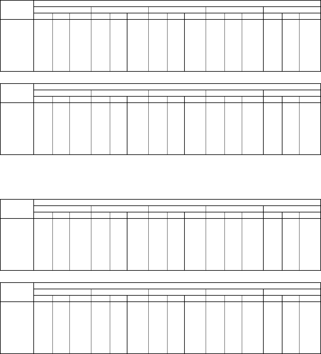
—29—
Table18—FanPerformance 580F060 — Three-Phase, Vertical Discharge Units,
Alternate Motor (Belt Drive)*
LEGEND
*Motor drive range: 878 to 1192 rpm. All other rpms require a field-
supplied drive.
NOTES:
1. Boldface indicates field-supplied drive is required.
2. Maximum continuous bhp is 2.40.
3. See page 36 for general fan performance notes.
Table19—FanPerformance 580F060 — Vertical Discharge Units, High-Static Motor (Belt Drive)*
LEGEND
*Motor drive range: 1300 to 1685 rpm. All other rpms require a field-supplied
drive.
NOTES:
1. Boldface indicates field-supplied drive is required.
2. Maximum continuous bhp is 2.90.
3. See page 36 for general fan performance notes.
AIRFLOW
(Cfm)
EXTERNAL STATIC PRESSURE (in. wg)
0.2 0.4 0.6 0.8 1.0
RpmBhp Watts RpmBhpWattsRpmBhpWattsRpmBhp Watts RpmBhp Watts
1500 802 0.42 370 912 0.55 489 1006 0.70 624 1088 0.87 773 1163 1.05 935
1600 840 0.49 432 947 0.63 557 1038 0.78 696 1119 0.95 848 1193 1.14 1013
1700 878 0.57 502 982 0.71 632 1071 0.87 776 1151 1.05 932 1224 1.24 1100
1800 917 0.65 581 1017 0.81 716 1105 0.97 864 1183 1.15 1024 1255 1.35 1197
1900 956 0.75 668 1053 0.91 808 1139 1.08 961 1216 1.27 1126 1287 1.47 1302
2000 995 0.86 764 1090 1.02 910 1173 1.20 1067 1249 1.39 1236 1319 1.59 1416
2100 1035 0.98 869 1127 1.15 1021 1209 1.33 1183 1283 1.53 1357 1351 1.74 1541
2200 1075 1.11 984 1164 1.29 1141 1244 1.47 1309 1317 1.68 1488 1385 1.89 1676
2300 1115 1.25 1110 1202 1.43 1273 1280 1.63 1446 1352 1.83 1629 1418 2.05 1822
2400 1155 1.40 1246 1240 1.59 1415 1316 1.79 1594 1387 2.01 1782 1452 2.23 1980
2500 1196 1.57 1394 1278 1.77 1569 1353 1.97 1753 1422 2.19 1946 —— —
AIRFLOW
(Cfm)
EXTERNAL STATIC PRESSURE (in. wg)
1.2 1.4 1.6 1.8 2.0
RpmBhp Watts RpmBhpWattsRpmBhpWattsRpmBhp Watts RpmBhp Watts
1500 1232 1.25 1109 1297 1.46 1295 1357 1.68 1492 1415 1.91 1700 1469 2.16 1917
1600 1262 1.34 1190 1325 1.55 1379 1385 1.78 1579 1442 2.01 1788 1496 2.26 2009
1700 1291 1.44 1281 1354 1.66 1472 1414 1.89 1674 1470 2.12 1887 1524 2.37 2109
1800 1322 1.55 1380 1384 1.77 1575 1443 2.00 1779 1499 2.25 1994 —— —
1900 1352 1.68 1489 1414 1.90 1687 1472 2.13 1894 1528 2.38 2112 —— —
2000 1384 1.81 1607 1445 2.04 1808 1502 2.27 2019 —— — —— —
2100 1415 1.95 1736 1476 2.18 1940 —— — —— — —— —
2200 1448 2.11 1875 1507 2.35 2083 —— — —— — —— —
2300 1480 2.28 2025 —— — —— — —— — —— —
2400 ——— ——— ——— ——— ———
2500 ——— ——— ——— ——— ———
Bhp—Brake Horsepower Input to Fan
Watts — Input Watts to Motor
AIRFLOW
(Cfm)
EXTERNAL STATIC PRESSURE (in. wg)
0.2 0.4 0.6 0.8 1.0
RpmBhp Watts RpmBhpWattsRpmBhpWattsRpmBhp Watts RpmBhp Watts
1500 802 0.42 370 912 0.55 489 1006 0.70 624 1088 0.87 773 1163 1.05 935
1600 840 0.49 432 947 0.63 557 1038 0.78 696 1119 0.95 848 1193 1.14 1013
1700 878 0.57 502 982 0.71 632 1071 0.87 776 1151 1.05 932 1224 1.24 1100
1800 917 0.65 581 1017 0.81 716 1105 0.97 864 1183 1.15 1024 1255 1.35 1197
1900 956 0.75 668 1053 0.91 808 1139 1.08 961 1216 1.27 1126 1287 1.47 1302
2000 995 0.86 764 1090 1.02 910 1173 1.20 1067 1249 1.39 1236 1319 1.59 1416
2100 1035 0.98 869 1127 1.15 1021 1209 1.33 1183 1283 1.53 1357 1351 1.74 1541
2200 1075 1.11 984 1164 1.29 1141 1244 1.47 1309 1317 1.68 1488 1385 1.89 1676
2300 1115 1.25 1110 1202 1.43 1273 1280 1.63 1446 1352 1.83 1629 1418 2.05 1822
2400 1155 1.40 1246 1240 1.59 1415 1316 1.79 1594 1387 2.01 1782 1452 2.23 1980
2500 1196 1.57 1394 1278 1.77 1569 1353 1.97 1753 1422 2.19 1946 1486 2.42 2149
AIRFLOW
(Cfm)
EXTERNAL STATIC PRESSURE (in. wg)
1.2 1.4 1.6 1.8 2.0
RpmBhp Watts RpmBhpWattsRpmBhpWattsRpmBhp Watts RpmBhp Watts
1500 1232 1.25 1109 1297 1.46 1295 1357 1.68 1492 1415 1.91 1700 1469 2.16 1917
1600 1262 1.34 1190 1325 1.55 1379 1385 1.78 1579 1442 2.01 1788 1496 2.26 2009
1700 1291 1.44 1281 1354 1.66 1472 1414 1.89 1674 1470 2.12 1887 1524 2.37 2109
1800 1322 1.55 1380 1384 1.77 1575 1443 2.00 1779 1499 2.25 1994 1552 2.50 2219
1900 1352 1.68 1489 1414 1.90 1687 1472 2.13 1894 1528 2.38 2112 1580 2.63 2339
2000 1384 1.81 1607 1445 2.04 1808 1502 2.27 2019 1557 2.52 2240 1609 2.78 2470
2100 1415 1.95 1736 1476 2.18 1940 1533 2.43 2155 1587 2.68 2378 — — —
2200 1448 2.11 1875 1507 2.35 2083 1563 2.59 2301 1617 2.85 2528 — — —
2300 1480 2.28 2025 1539 2.52 2237 1595 2.77 2459 — — — — — —
2400 1513 2.46 2187 1571 2.71 2403 — — — — — — — — —
2500 1547 2.66 2360 — — — — — — — — — — — —
Bhp—Brake Horsepower Input to Fan
Watts — Input Watts to Motor
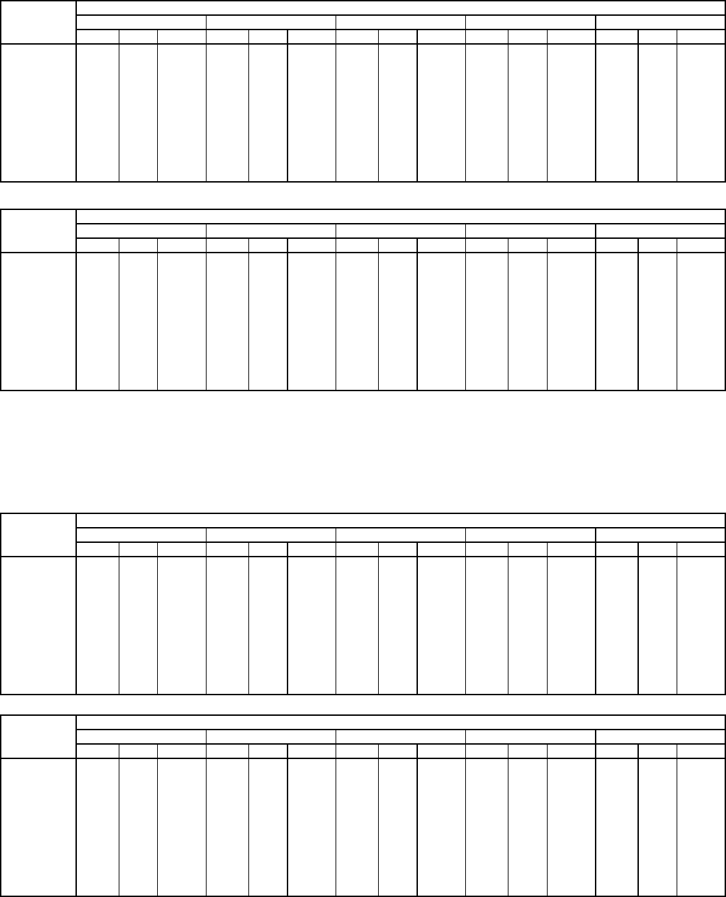
—30—
Table 20 — Fan Performance 580F072,073 — Vertical Discharge Units, Standard Motor (Belt Drive)*
LEGEND
*Motor drive range: 1070 to 1460 rpm. All other rpms require a field-supplied
drive.
NOTES:
1. Boldface indicates field-supplied drive is required.
2. Maximum continuous bhp is 2.40.
3. See page 36 for general fan performance notes.
Table21—FanPerformance 580F072,073 — Vertical Discharge Units, High-Static Motor (Belt Drive)*
LEGEND
*Motor drive range: 1300 to 1685 rpm. All other rpms require a field-supplied
drive.
NOTES:
1. Boldface indicates field-supplied drive is required.
2. Maximum continuous bhp is 2.90.
3. See page 36 for general fan performance notes.
AIRFLOW
(Cfm)
EXTERNAL STATIC PRESSURE (in. wg)
0.2 0.4 0.6 0.8 1.0
RpmBhp Watts RpmBhpWattsRpmBhpWattsRpmBhp Watts RpmBhp Watts
1800 967 0.65 579 1077 0.81 718 1172 0.96 856 1257 1.12 993 1334 1.27 1130
1900 1007 0.75 663 1115 0.91 811 1208 1.08 957 1291 1.24 1101 1368 1.40 1246
2000 1048 0.85 757 1153 1.03 913 1244 1.20 1066 1326 1.37 1219 1401 1.54 1371
2100 1090 0.97 859 1191 1.15 1023 1281 1.33 1185 1361 1.51 1345 1435 1.69 1505
2200 1131 1.09 970 1230 1.29 1143 1318 1.48 1313 1397 1.67 1481 1470 1.86 1649
2300 1173 1.23 1091 1269 1.43 1273 1355 1.63 1451 1433 1.83 1627 1505 2.03 1803
2400 1215 1.38 1223 1309 1.59 1413 1393 1.80 1600 1470 2.01 1784 1540 2.21 1967
2500 1258 1.54 1365 1349 1.76 1564 1431 1.98 1759 1506 2.20 1951 —— —
2600 1300 1.71 1518 1389 1.94 1726 1470 2.17 1929 1544 2.40 2130 —— —
2700 1343 1.90 1683 1430 2.14 1899 1509 2.38 2111 —— — —— —
2800 1386 2.09 1860 1471 2.35 2085 —— — —— — —— —
2900 1429 2.31 2050 — — — — — — — — — — — —
3000 ——— ——— ——— ——— ———
AIRFLOW
(Cfm)
EXTERNAL STATIC PRESSURE (in. wg)
1.2 1.4 1.6 1.8 2.0
RpmBhp Watts RpmBhpWattsRpmBhpWattsRpmBhp Watts RpmBhp Watts
1800 1406 1.43 1268 1473 1.58 1407 1535 1.74 1548 1595 1.90 1690 1652 2.06 1833
1900 1438 1.57 1391 1504 1.73 1537 1567 1.90 1685 1626 2.06 1833 1682 2.23 1983
2000 1471 1.72 1523 1536 1.89 1677 1598 2.06 1831 1657 2.24 1986 —— —
2100 1504 1.87 1665 1569 2.06 1825 1630 2.24 1986 —— — —— —
2200 1538 2.04 1816 1602 2.23 1984 —— — —— — —— —
2300 1572 2.23 1978 —— — —— — —— — —— —
2400 ——— ——— ——— ——— ———
2500 ——— ——— ——— ——— ———
2600 ——— ——— ——— ——— ———
2700 ——— ——— ——— ——— ———
2800 ——— ——— ——— ——— ———
2900 ——— ——— ——— ——— ———
3000 ——— ——— ——— ——— ———
Bhp—Brake Horsepower Input to Fan
Watts — Input Watts to Motor
AIRFLOW
(Cfm)
EXTERNAL STATIC PRESSURE (in. wg)
0.2 0.4 0.6 0.8 1.0
RpmBhp Watts RpmBhpWattsRpmBhpWattsRpmBhp Watts RpmBhp Watts
1800 967 0.65 579 1077 0.81 718 1172 0.96 856 1257 1.12 993 1334 1.27 1130
1900 1007 0.75 663 1115 0.91 811 1208 1.08 957 1291 1.24 1101 1368 1.40 1246
2000 1048 0.85 757 1153 1.03 913 1244 1.20 1066 1326 1.37 1219 1401 1.54 1371
2100 1090 0.97 859 1191 1.15 1023 1281 1.33 1185 1361 1.51 1345 1435 1.69 1505
2200 1131 1.09 970 1230 1.29 1143 1318 1.48 1313 1397 1.67 1481 1470 1.86 1649
2300 1173 1.23 1091 1269 1.43 1273 1355 1.63 1451 1433 1.83 1627 1505 2.03 1803
2400 1215 1.38 1223 1309 1.59 1413 1393 1.80 1600 1470 2.01 1784 1540 2.21 1967
2500 1258 1.54 1365 1349 1.76 1564 1431 1.98 1759 1506 2.20 1951 1576 2.41 2142
2600 1300 1.71 1518 1389 1.94 1726 1470 2.17 1929 1544 2.40 2130 1613 2.62 2329
2700 1343 1.90 1683 1430 2.14 1899 1509 2.38 2111 1581 2.61 2320 1649 2.85 2527
2800 1386 2.09 1860 1471 2.35 2085 1548 2.60 2305 1619 2.84 2522 — — —
2900 1429 2.31 2050 1512 2.57 2283 1588 2.83 2512 — — — — — —
3000 1473 2.54 2252 1553 2.81 2494 — — — — — — — — —
AIRFLOW
(Cfm)
EXTERNAL STATIC PRESSURE (in. wg)
1.2 1.4 1.6 1.8 2.0
RpmBhp Watts RpmBhpWattsRpmBhpWattsRpmBhp Watts RpmBhp Watts
1800 1406 1.43 1268 1473 1.58 1407 1535 1.74 1548 1595 1.90 1690 1652 2.06 1833
1900 1438 1.57 1391 1504 1.73 1537 1567 1.90 1685 1626 2.06 1833 1682 2.23 1983
2000 1471 1.72 1523 1536 1.89 1677 1598 2.06 1831 1657 2.24 1986 1713 2.41 2142
2100 1504 1.87 1665 1569 2.06 1825 1630 2.24 1986 1688 2.42 2149 1744 2.60 2312
2200 1538 2.04 1816 1602 2.23 1984 1663 2.42 2152 1720 2.61 2321 1775 2.81 2491
2300 1572 2.23 1978 1635 2.42 2153 1695 2.62 2328 1753 2.82 2504 —— —
2400 1607 2.42 2150 1669 2.63 2332 1729 2.83 2515 —— — —— —
2500 1642 2.63 2333 1704 2.84 2523 —— — —— — —— —
2600 1677 2.85 2527 — — — — — — — — — — — —
2700 ——— ——— ——— ——— ———
2800 ——— ——— ——— ——— ———
2900 ——— ——— ——— ——— ———
3000 ——— ——— ——— ——— ———
Bhp—Brake Horsepower Input to Fan
Watts — Input Watts to Motor
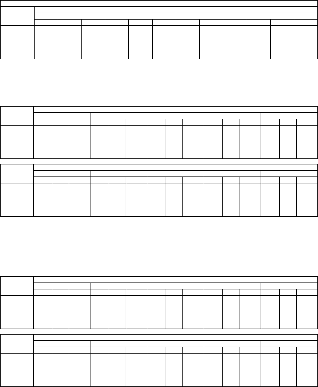
—31—
Table22—FanPerformance 580F036 — Horizontal Discharge Units, Standard Motor
LEGEND See page 36 for general fan performance notes.
Table23—FanPerformance 580F036 — Horizontal Discharge Units, Alternate Motor (Belt Drive)*
LEGEND
*Motor drive range: 685 to 1045 rpm. All other rpms require a field-
supplied drive.
NOTES:
1. Boldface indicates field-supplied drive is required.
2. Maximum continuous bhp is 1.20.
3. See page 36 for general fan performance notes.
Table24—FanPerformance 580F036 — Horizontal Discharge Units, High-Static Motor (Belt Drive)*
LEGEND
*Motor drive range: 1075 to 1455 rpm. All other rpms require a field-supplied
drive.
NOTES:
1. Boldface indicates field-supplied drive is required.
2. Maximum continuous bhp is 2.40.
3. See page 36 for general fan performance notes.
STANDARD MOTOR (DIRECT DRIVE)
Airflow
(Cfm)
Low Speed HighSpeed
208 V 230, 460, 575 V 208 V 230, 460, 575 V
ESP BhpWattsESP Bhp Watts ESP Bhp Watts ESP BhpWatts
900 0.54 0.21 253 0.57 0.23 277 0.55 0.26 307 0.60 0.31 363
1000 0.49 0.23 270 0.51 0.25 292 0.52 0.27 321 0.53 0.32 374
1100 0.43 0.24 287 0.45 0.26 307 0.46 0.28 335 0.49 0.33 385
1200 0.39 0.26 304 0.40 0.27 323 0.38 0.29 349 0.43 0.34 397
1300 0.33 0.27 321 0.35 0.29 338 0.35 0.31 364 0.36 0.34 408
1400 0.26 0.29 338 0.28 0.30 354 0.29 0.32 378 — — —
1500 0.21 0.30 355 0.23 0.31 369 0.24 0.33 392 — — —
Bhp—Brake Horsepower Input to Fan
ESP — External Static Pressure (in. wg)
AIRFLOW
(Cfm)
EXTERNAL STATIC PRESSURE (in. wg)
0.2 0.4 0.6 0.8 1.0
RpmBhp Watts RpmBhpWattsRpmBhpWattsRpmBhp Watts RpmBhp Watts
900 607 0.14 142 745 0.22 221 856 0.31 304 952 0.39 393 1037 0.49 485
1000 640 0.18 174 775 0.26 261 884 0.35 351 978 0.45 446 1062 0.55 545
1100 674 0.21 212 805 0.31 307 912 0.41 404 1005 0.51 506 1089 0.61 611
1200 708 0.26 256 836 0.36 359 941 0.47 464 1033 0.57 572 1116 0.69 683
1300 743 0.31 307 868 0.42 417 971 0.53 530 1062 0.65 645 1143 0.77 764
1400 780 0.37 364 900 0.49 483 1002 0.61 603 1091 0.73 726 1172 0.86 851
1500 816 0.43 428 934 0.56 556 1033 0.69 685 1121 0.82 815 1201 0.95 947
AIRFLOW
(Cfm)
EXTERNAL STATIC PRESSURE (in. wg)
1.2 1.4 1.6 1.8 2.0
RpmBhp Watts RpmBhpWattsRpmBhpWattsRpmBhp Watts RpmBhp Watts
900 1114 0.59 582 1186 0.69 684 1253 0.79 789 1316 0.90 898 1375 1.02 1010
1000 1139 0.65 648 1210 0.76 754 1277 0.87 865 1340 0.98 979 1399 1.10 1097
1100 1165 0.72 720 1236 0.84 832 1302 0.95 948 1364 1.07 1068 1423 1.20 1191
1200 1191 0.80 799 1261 0.92 917 1327 1.04 1039 1389 1.17 1165 —— —
1300 1218 0.89 885 1288 1.02 1010 1353 1.14 1138 —— — —— —
1400 1246 0.99 980 1315 1.12 1111 —— — —— — —— —
1500 1274 1.09 1083 —— — —— — —— — —— —
Bhp—Brake Horsepower Input to Fan
Watts — Input Watts to Motor
AIRFLOW
(Cfm)
EXTERNAL STATIC PRESSURE (in. wg)
0.2 0.4 0.6 0.8 1.0
RpmBhp Watts RpmBhpWattsRpmBhpWattsRpmBhp Watts RpmBhp Watts
900 607 0.14 142 745 0.22 221 856 0.31 304 952 0.39 393 1037 0.49 485
1000 640 0.18 174 775 0.26 261 884 0.35 351 978 0.45 446 1062 0.55 545
1100 674 0.21 212 805 0.31 307 912 0.41 404 1005 0.51 506 1089 0.61 611
1200 708 0.26 256 836 0.36 359 941 0.47 464 1033 0.57 572 1116 0.69 683
1300 743 0.31 307 868 0.42 417 971 0.53 530 1062 0.65 645 1143 0.77 764
1400 780 0.37 364 900 0.49 483 1002 0.61 603 1091 0.73 726 1172 0.86 851
1500 816 0.43 428 934 0.56 556 1033 0.69 685 1121 0.82 815 1201 0.95 947
AIRFLOW
(Cfm)
EXTERNAL STATIC PRESSURE (in. wg)
1.2 1.4 1.6 1.8 2.0
RpmBhp Watts RpmBhpWattsRpmBhpWattsRpmBhp Watts RpmBhp Watts
900 1114 0.59 582 1186 0.69 684 1253 0.79 789 1316 0.90 898 1375 1.02 1010
1000 1139 0.65 648 1210 0.76 754 1277 0.87 865 1340 0.98 979 1399 1.10 1097
1100 1165 0.72 720 1236 0.84 832 1302 0.95 948 1364 1.07 1068 1423 1.20 1191
1200 1191 0.80 799 1261 0.92 917 1327 1.04 1039 1389 1.17 1165 1448 1.30 1293
1300 1218 0.89 885 1288 1.02 1010 1353 1.14 1138 1414 1.28 1270 1473 1.41 1404
1400 1246 0.99 980 1315 1.12 1111 1379 1.25 1246 1440 1.39 1383 1499 1.53 1523
1500 1274 1.09 1083 1342 1.23 1221 1406 1.37 1362 1467 1.51 1505 1525 1.66 1652
Bhp—Brake Horsepower Input to Fan
Watts — Input Watts to Motor
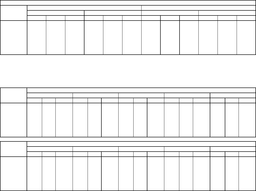
—32—
Table25—FanPerformance 580F048 — Horizontal Discharge Units, Standard Motor
LEGEND See page 36 for general fan performance notes.
Table26—FanPerformance 580F048 — Horizontal Discharge Units, Alternate Motor (Belt Drive)*
LEGEND
*Motor drive range: 770 to 1175 rpm. All other rpms require a field-
supplied drive.
NOTES:
1. Boldface indicates field-supplied drive is required.
2. Maximum continuous bhp is 1.20.
3. See page 36 for general fan performance notes.
STANDARD MOTOR (DIRECT DRIVE)
Airflow
(Cfm)
Low Speed HighSpeed
208 V 230, 460, 575 V 208 V 230, 460, 575 V
ESP Bhp Watts ESP Bhp Watts ESP BhpWattsESP Bhp Watts
1200 0.75 0.41 458 0.81 0.45 506 0.87 0.51 572 0.92 0.56 632
1300 0.68 0.42 471 0.74 0.46 521 0.79 0.52 589 0.85 0.58 651
1400 0.60 0.45 503 0.66 0.49 556 0.71 0.54 616 0.77 0.60 681
1500 0.51 0.47 536 0.58 0.52 593 0.64 0.56 631 0.70 0.62 698
1600 0.42 0.49 557 0.49 0.54 616 0.56 0.58 654 0.63 0.64 723
1700 0.32 0.52 584 0.39 0.57 646 0.48 0.60 678 0.55 0.66 750
1800 0.21 0.54 610 0.29 0.60 674 0.41 0.62 698 0.48 0.68 772
1900 0.09 0.56 629 0.18 0.62 696 0.33 0.64 720 0.41 0.70 796
2000 — — — 0.06 0.65 731 0.26 0.66 744 0.33 0.73 823
Bhp—Brake Horsepower Input to Fan
ESP — External Static Pressure (in. wg)
AIRFLOW
(Cfm)
EXTERNAL STATIC PRESSURE (in. wg)
0.2 0.4 0.6 0.8 1.0
RpmBhp Watts RpmBhpWattsRpmBhpWattsRpmBhp Watts RpmBhp Watts
1200 643 0.23 234 762 0.34 343 859 0.46 458 944 0.58 579 1020 0.71 705
1300 675 0.28 277 790 0.40 394 886 0.52 517 969 0.65 644 1044 0.78 777
1400 707 0.33 326 819 0.45 452 913 0.58 581 996 0.72 716 1070 0.86 855
1500 740 0.38 382 849 0.52 515 941 0.66 653 1023 0.80 795 1096 0.95 941
1600 773 0.45 444 879 0.59 586 970 0.73 731 1050 0.88 880 1123 1.04 1034
1700 807 0.52 513 910 0.67 663 999 0.82 817 1078 0.98 973 1150 1.14 1134
1800 841 0.59 589 942 0.75 749 1029 0.91 910 1106 1.08 1074 — — —
1900 875 0.68 674 974 0.85 842 1059 1.02 1012 1135 1.19 1184 — — —
2000 910 0.77 767 1006 0.95 944 1090 1.13 1122 — — — — — —
AIRFLOW
(Cfm)
EXTERNAL STATIC PRESSURE (in. wg)
1.2 1.4 1.6 1.8 2.0
RpmBhp Watts RpmBhpWattsRpmBhpWattsRpmBhp Watts RpmBhp Watts
1200 1089 0.84 837 1153 0.98 974 1213 1.12 1115 —— — —— —
1300 1113 0.92 915 1177 1.06 1058 —— — —— — —— —
1400 1138 1.01 1000 1201 1.15 1149 —— — —— — —— —
1500 1163 1.10 1092 — — — — — — — — — — — —
1600 1189 1.20 1191 —— — —— — —— — —— —
1700 ——— ——— ——— ——— ———
1800 ——— ——— ——— ——— ———
1900 ——— ——— ——— ——— ———
2000 ——— ——— ——— ——— ———
Bhp—Brake Horsepower Input to Fan
Watts — Input Watts to Motor

—33—
Table27—FanPerformance 580F048 — Horizontal Discharge Units, High-Static Motor (Belt Drive)*
LEGEND
*Motor drive range: 1075 to 1455 rpm. All other rpms require a field-supplied
drive.
NOTES:
1. Boldface indicates field-supplied drive is required.
2. Maximum continuous bhp is 2.40.
3. See page 36 for general fan performance notes.
Table28—FanPerformance 580F060 — Horizontal Discharge Units, Standard Motor
LEGEND See page 36 for general fan performance notes.
AIRFLOW
(Cfm)
EXTERNAL STATIC PRESSURE (in. wg)
0.2 0.4 0.6 0.8 1.0
RpmBhp Watts RpmBhpWattsRpmBhpWattsRpmBhp Watts RpmBhp Watts
1200 643 0.23 234 762 0.34 343 859 0.46 458 944 0.58 579 1020 0.71 705
1300 675 0.28 277 790 0.40 394 886 0.52 517 969 0.65 644 1044 0.78 777
1400 707 0.33 326 819 0.45 452 913 0.58 581 996 0.72 716 1070 0.86 855
1500 740 0.38 382 849 0.52 515 941 0.66 653 1023 0.80 795 1096 0.95 941
1600 773 0.45 444 879 0.59 586 970 0.73 731 1050 0.88 880 1123 1.04 1034
1700 807 0.52 513 910 0.67 663 999 0.82 817 1078 0.98 973 1150 1.14 1134
1800 841 0.59 589 942 0.75 749 1029 0.91 910 1106 1.08 1074 1177 1.25 1242
1900 875 0.68 674 974 0.85 842 1059 1.02 1012 1135 1.19 1184 1205 1.37 1360
2000 910 0.77 767 1006 0.95 944 1090 1.13 1122 1165 1.31 1302 1234 1.49 1485
AIRFLOW
(Cfm)
EXTERNAL STATIC PRESSURE (in. wg)
1.2 1.4 1.6 1.8 2.0
RpmBhp Watts RpmBhpWattsRpmBhpWattsRpmBhp Watts RpmBhp Watts
1200 1089 0.84 837 1153 0.98 974 1213 1.12 1115 1270 1.27 1262 1324 1.42 1413
1300 1113 0.92 915 1177 1.06 1058 1237 1.21 1205 1293 1.36 1358 1347 1.52 1514
1400 1138 1.01 1000 1201 1.15 1149 1261 1.31 1303 1317 1.47 1461 1370 1.63 1623
1500 1163 1.10 1092 1226 1.25 1247 1285 1.41 1407 1341 1.58 1571 1394 1.75 1740
1600 1189 1.20 1191 1252 1.36 1353 1310 1.53 1520 1365 1.70 1690 1418 1.87 1865
1700 1216 1.31 1299 1277 1.48 1468 1335 1.65 1640 1390 1.83 1817 1442 2.01 1998
1800 1242 1.42 1414 1303 1.60 1590 1361 1.78 1770 1415 1.96 1953 1467 2.15 2140
1900 1270 1.55 1538 1330 1.73 1721 1387 1.92 1908 1441 2.11 2098 1493 2.30 2292
2000 1297 1.68 1672 1357 1.87 1862 1414 2.07 2055 1467 2.26 2252 —— —
Bhp—Brake Horsepower Input to Fan
Watts — Input Watts to Motor
STANDARD MOTOR (DIRECT DRIVE)
Airflow
(Cfm)
Low Speed MediumSpeed HighSpeed
208V 230, 460, 575 V 208 V 230, 460, 575 V 208 V 230, 460, 575 V
ESP Bhp Watts ESP BhpWattsESP Bhp Watts ESP Bhp Watts ESP Bhp Watts ESP Bhp Watts
1500 0.74 0.67 750 1.06 0.71 791 1.07 0.70 782 1.27 0.76 845 1.26 0.79 875 1.33 0.85 949
1600 0.54 0.70 780 0.90 0.74 824 0.92 0.74 821 1.13 0.79 883 1.14 0.82 913 1.22 0.89 988
1700 0.34 0.73 810 0.75 0.77 857 0.77 0.77 861 1.00 0.83 921 1.01 0.85 950 1.11 0.92 1027
1800 0.14 0.75 839 0.59 0.80 891 0.62 0.81 900 0.87 0.86 959 0.89 0.88 988 1.00 0.96 1066
1900 — — — 0.44 0.83 924 0.47 0.84 940 0.74 0.90 997 0.77 0.92 1025 0.89 0.99 1105
2000 — — — 0.28 0.86 957 0.32 0.88 979 0.61 0.93 1035 0.64 0.95 1063 0.78 1.03 1144
2100 — — — 0.13 0.89 990 0.17 0.91 1018 0.48 0.96 1073 0.51 0.99 1101 0.67 1.06 1183
2200 — — — — — — 0.02 0.95 1058 0.35 1.00 1111 0.39 1.02 1138 0.56 1.10 1222
2300 — — — — — — — — — 0.22 1.03 1149 0.26 1.06 1176 0.45 1.13 1261
2400 — — — — — — — — — 0.09 1.07 1187 0.14 1.09 1213 0.34 1.17 1300
2500 ———————————————0.231.201340
Bhp—Brake Horsepower Input to Fan
ESP — External Static Pressure (in. wg)
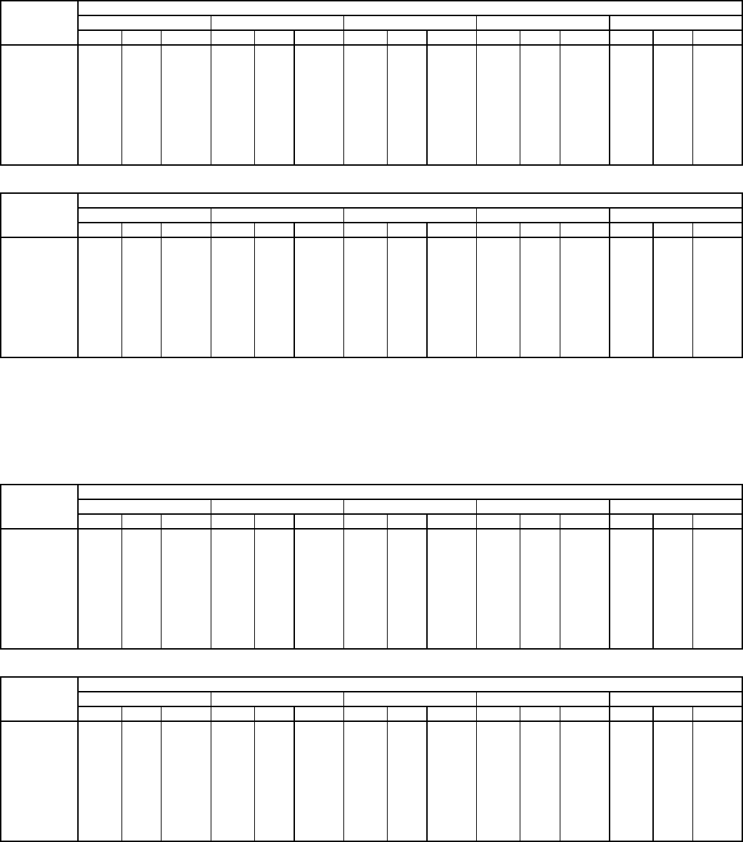
—34—
Table29—FanPerformance 580F060 — Single-Phase, Horizontal Discharge Units,
Alternate Motor (Belt Drive)*
LEGEND
*Motor drive range: 875 to 1192 rpm. All other rpms require a field-
supplied drive.
NOTES:
1. Boldface indicates field-supplied drive is required.
2. Maximum continuous bhp is 1.30.
3. See page 36 for general fan performance notes.
Table30—FanPerformance 580F060 — Three-Phase, Horizontal Discharge Units,
Alternate Motor (Belt Drive)*
LEGEND
*Motor drive range: 878 to 1192 rpm. All other rpms require a field-
supplied drive.
NOTES:
1. Boldface indicates field-supplied drive is required.
2. Maximum continuous bhp is 2.40.
3. See page 36 for general fan performance notes.
AIRFLOW
(Cfm)
EXTERNAL STATIC PRESSURE (in. wg)
0.2 0.4 0.6 0.8 1.0
RpmBhp Watts RpmBhpWattsRpmBhpWattsRpmBhp Watts RpmBhp Watts
1500 790 0.40 353 896 0.53 470 990 0.67 599 1074 0.83 738 1151 1.00 886
1600 828 0.46 413 930 0.60 535 1021 0.75 669 1103 0.91 812 1179 1.09 965
1700 866 0.54 479 964 0.68 607 1053 0.84 746 1133 1.01 894 1207 1.18 1051
1800 905 0.62 553 1000 0.77 687 1085 0.94 831 1164 1.11 984 1236 1.29 1146
1900 944 0.71 635 1036 0.87 775 1119 1.04 924 1195 1.22 1082 —— —
2000 984 0.82 725 1072 0.98 871 1153 1.15 1025 — — — — — —
2100 1024 0.93 824 1109 1.10 976 1188 1.28 1136 — — — — — —
2200 1064 1.05 932 1147 1.23 1090 — — — — — — — — —
2300 1105 1.18 1050 — — — — — — — — — — — —
2400 ——— ——— ——— ——— ———
2500 ——— ——— ——— ——— ———
AIRFLOW
(Cfm)
EXTERNAL STATIC PRESSURE (in. wg)
1.2 1.4 1.6 1.8 2.0
RpmBhp Watts RpmBhpWattsRpmBhpWattsRpmBhp Watts RpmBhp Watts
1500 1223 1.18 1045 —— — —— — —— — —— —
1600 1249 1.27 1127 —— — —— — —— — —— —
1700 ——— ——— ——— ——— ———
1800 ——— ——— ——— ——— ———
1900 ——— ——— ——— ——— ———
2000 ——— ——— ——— ——— ———
2100 ——— ——— ——— ——— ———
2200 ——— ——— ——— ——— ———
2300 ——— ——— ——— ——— ———
2400 ——— ——— ——— ——— ———
2500 ——— ——— ——— ——— ———
Bhp—Brake Horsepower Input to Fan
Watts — Input Watts to Motor
AIRFLOW
(Cfm)
EXTERNAL STATIC PRESSURE (in. wg)
0.2 0.4 0.6 0.8 1.0
RpmBhp Watts RpmBhpWattsRpmBhpWattsRpmBhp Watts RpmBhp Watts
1500 790 0.40 353 896 0.53 470 990 0.67 599 1074 0.83 738 1151 1.00 886
1600 828 0.46 413 930 0.60 535 1021 0.75 669 1103 0.91 812 1179 1.09 965
1700 866 0.54 479 964 0.68 607 1053 0.84 746 1133 1.01 894 1207 1.18 1051
1800 905 0.62 553 1000 0.77 687 1085 0.94 831 1164 1.11 984 1236 1.29 1146
1900 944 0.71 635 1036 0.87 775 1119 1.04 924 1195 1.22 1082 1266 1.41 1248
2000 984 0.82 725 1072 0.98 871 1153 1.15 1025 1227 1.34 1189 1297 1.53 1360
2100 1024 0.93 824 1109 1.10 976 1188 1.28 1136 1260 1.47 1305 1328 1.67 1481
2200 1064 1.05 932 1147 1.23 1090 1223 1.41 1256 1294 1.61 1430 1360 1.81 1612
2300 1105 1.18 1050 1185 1.37 1215 1259 1.56 1386 1328 1.76 1566 1393 1.97 1752
2400 1146 1.33 1179 1223 1.52 1349 1295 1.72 1527 1362 1.93 1711 1426 2.14 1903
2500 1187 1.48 1317 1262 1.68 1494 1332 1.89 1677 1398 2.10 1868 1460 2.33 2065
AIRFLOW
(Cfm)
EXTERNAL STATIC PRESSURE (in. wg)
1.2 1.4 1.6 1.8 2.0
RpmBhp Watts RpmBhpWattsRpmBhpWattsRpmBhp Watts RpmBhp Watts
1500 1223 1.18 1045 1291 1.36 1212 1355 1.56 1388 1415 1.77 1573 1473 1.99 1765
1600 1249 1.27 1127 1316 1.46 1298 1379 1.66 1478 1439 1.87 1665 1496 2.09 1860
1700 1277 1.37 1217 1342 1.57 1392 1404 1.77 1575 1463 1.99 1766 1520 2.21 1965
1800 1305 1.48 1316 1369 1.68 1495 1430 1.89 1681 1489 2.11 1876 1545 2.34 2078
1900 1333 1.60 1423 1397 1.81 1606 1457 2.02 1797 1514 2.25 1995 —— —
2000 1363 1.73 1540 1425 1.94 1727 1484 2.16 1922 1541 2.39 2124 —— —
2100 1393 1.87 1665 1454 2.09 1857 1512 2.31 2056 —— — —— —
2200 1424 2.03 1801 1484 2.25 1997 —— — —— — —— —
2300 1455 2.19 1946 —— — —— — —— — —— —
2400 1487 2.37 2103 —— — —— — —— — —— —
2500 ——— ——— ——— ——— ———
Bhp—Brake Horsepower Input to Fan
Watts — Input Watts to Motor
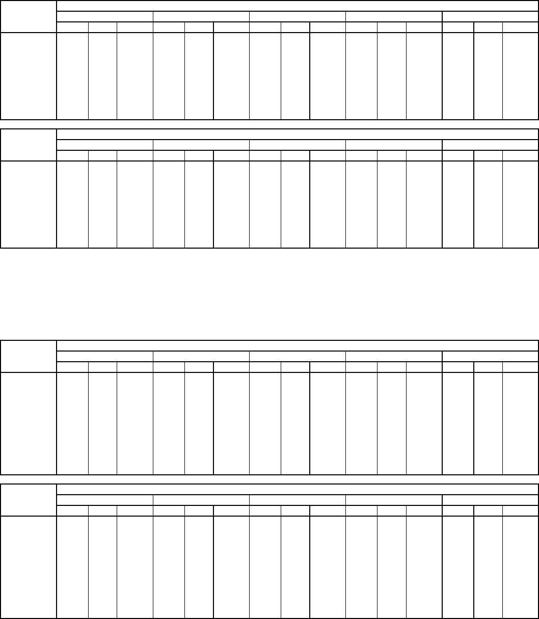
—35—
Table31—FanPerformance 580F060 — Horizontal Discharge Units, High-Static Motor (Belt Drive)*
LEGEND
*Motor drive range: 1300 to 1685 rpm. All other rpms require a field-supplied
drive.
NOTES:
1. Boldface indicates field-supplied drive is required.
2. Maximum continuous bhp is 2.90.
3. See page 36 for general fan performance notes.
Table32—FanPerformance 580F072,073 — Horizontal Discharge Units, Standard Motor (Belt Drive)*
LEGEND
*Motor drive range: 1070 to 1460 rpm. All other rpms require a field-supplied
drive.
NOTES:
1. Boldface indicates field-supplied drive is required.
2. Maximum continuous bhp is 2.40.
3. See page 36 for general fan performance notes.
AIRFLOW
(Cfm)
EXTERNAL STATIC PRESSURE (in. wg)
0.2 0.4 0.6 0.8 1.0
RpmBhp Watts RpmBhpWattsRpmBhpWattsRpmBhp Watts RpmBhp Watts
1500 790 0.40 353 896 0.53 470 990 0.67 599 1074 0.83 738 1151 1.00 886
1600 828 0.46 413 930 0.60 535 1021 0.75 669 1103 0.91 812 1179 1.09 965
1700 866 0.54 479 964 0.68 607 1053 0.84 746 1133 1.01 894 1207 1.18 1051
1800 905 0.62 553 1000 0.77 687 1085 0.94 831 1164 1.11 984 1236 1.29 1146
1900 944 0.71 635 1036 0.87 775 1119 1.04 924 1195 1.22 1082 1266 1.41 1248
2000 984 0.82 725 1072 0.98 871 1153 1.15 1025 1227 1.34 1189 1297 1.53 1360
2100 1024 0.93 824 1109 1.10 976 1188 1.28 1136 1260 1.47 1305 1328 1.67 1481
2200 1064 1.05 932 1147 1.23 1090 1223 1.41 1256 1294 1.61 1430 1360 1.81 1612
2300 1105 1.18 1050 1185 1.37 1215 1259 1.56 1386 1328 1.76 1566 1393 1.97 1752
2400 1146 1.33 1179 1223 1.52 1349 1295 1.72 1527 1362 1.93 1711 1426 2.14 1903
2500 1187 1.48 1317 1262 1.68 1494 1332 1.89 1677 1398 2.10 1868 1460 2.33 2065
AIRFLOW
(Cfm)
EXTERNAL STATIC PRESSURE (in. wg)
1.2 1.4 1.6 1.8 2.0
RpmBhp Watts RpmBhpWattsRpmBhpWattsRpmBhp Watts RpmBhp Watts
1500 1223 1.18 1045 1291 1.36 1212 1355 1.56 1388 1415 1.77 1573 1473 1.99 1765
1600 1249 1.27 1127 1316 1.46 1298 1379 1.66 1478 1439 1.87 1665 1496 2.09 1860
1700 1277 1.37 1217 1342 1.57 1392 1404 1.77 1575 1463 1.99 1766 1520 2.21 1965
1800 1305 1.48 1316 1369 1.68 1495 1430 1.89 1681 1489 2.11 1876 1545 2.34 2078
1900 1333 1.60 1423 1397 1.81 1606 1457 2.02 1797 1514 2.25 1995 1570 2.48 2200
2000 1363 1.73 1540 1425 1.94 1727 1484 2.16 1922 1541 2.39 2124 1596 2.63 2333
2100 1393 1.87 1665 1454 2.09 1857 1512 2.31 2056 1568 2.55 2262 1622 2.79 2475
2200 1424 2.03 1801 1484 2.25 1997 1541 2.48 2200 1596 2.71 2411 — — —
2300 1455 2.19 1946 1514 2.42 2147 1571 2.65 2355 1625 2.89 2570 — — —
2400 1487 2.37 2103 1545 2.60 2308 1601 2.84 2521 — — — — — —
2500 1520 2.56 2269 1577 2.79 2480 — — — — — — — — —
Bhp—Brake Horsepower Input to Fan
Watts — Input Watts to Motor
AIRFLOW
(Cfm)
EXTERNAL STATIC PRESSURE (in. wg)
0.2 0.4 0.6 0.8 1.0
RpmBhp Watts RpmBhpWattsRpmBhpWattsRpmBhp Watts RpmBhp Watts
1800 919 0.63 561 1010 0.75 663 1095 0.87 771 1174 1.00 886 1250 1.14 1008
1900 960 0.73 648 1047 0.85 754 1129 0.98 867 1206 1.11 986 1279 1.25 1111
2000 1001 0.84 744 1085 0.96 855 1163 1.09 972 1238 1.23 1095 1309 1.38 1224
2100 1043 0.96 850 1123 1.09 965 1199 1.22 1086 1271 1.37 1213 1340 1.52 1346
2200 1085 1.09 966 1162 1.22 1086 1235 1.36 1211 1305 1.51 1342 1372 1.67 1479
2300 1127 1.23 1092 1201 1.37 1217 1272 1.52 1347 1340 1.67 1482 1405 1.83 1623
2400 1169 1.38 1229 1241 1.53 1359 1310 1.68 1493 1375 1.84 1633 1439 2.00 1778
2500 1212 1.55 1378 1281 1.70 1513 1348 1.86 1652 1412 2.02 1796 1473 2.19 1945
2600 1255 1.73 1539 1322 1.89 1678 1386 2.05 1822 1448 2.22 1970 1508 2.39 2124
2700 1298 1.93 1713 1363 2.09 1857 1425 2.26 2005 — — — — — —
2800 1341 2.14 1899 1404 2.31 2048 — — — — — — — — —
2900 1384 2.36 2099 — — — — — — — — — — — —
3000 ——— ——— ——— ——— ———
AIRFLOW
(Cfm)
EXTERNAL STATIC PRESSURE (in. wg)
1.2 1.4 1.6 1.8 2.0
RpmBhp Watts RpmBhpWattsRpmBhpWattsRpmBhp Watts RpmBhp Watts
1800 1321 1.28 1137 1390 1.43 1273 1455 1.59 1415 1518 1.76 1563 1579 1.93 1718
1900 1348 1.40 1243 1415 1.56 1381 1479 1.72 1526 1541 1.89 1677 1601 2.06 1834
2000 1377 1.53 1359 1442 1.69 1500 1505 1.86 1648 1565 2.03 1801 1624 2.21 1961
2100 1406 1.67 1485 1470 1.83 1629 1531 2.00 1780 1591 2.18 1936 1648 2.36 2098
2200 1437 1.83 1621 1499 1.99 1769 1559 2.16 1923 1617 2.34 2082 —— —
2300 1468 1.99 1769 1529 2.16 1920 1587 2.34 2077 —— — —— —
2400 1500 2.17 1928 1559 2.35 2083 —— — —— — —— —
2500 1533 2.36 2098 —— — —— — —— — —— —
2600 ——— ——— ——— ——— ———
2700 ——— ——— ——— ——— ———
2800 ——— ——— ——— ——— ———
2900 ——— ——— ——— ——— ———
3000 ——— ——— ——— ——— ———
Bhp—Brake Horsepower Input to Fan
Watts — Input Watts to Motor
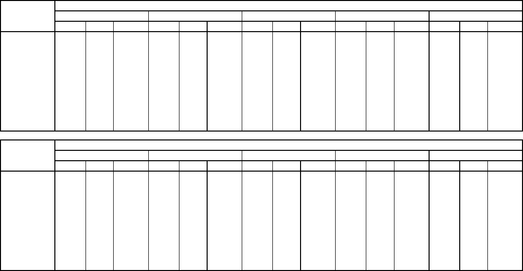
—36—
Table 33 — Fan Performance 580F072,073 — Horizontal Discharge Units, High-Static Motor (Belt Drive)*
LEGEND
*Motor drive range: 1300 to 1685 rpm. All other rpms require a field-supplied
drive.
NOTES:
1. Boldface indicates field-supplied drive is required.
2. Maximum continuous bhp is 2.90.
3. See below for general fan performance notes.
GENERAL FAN PERFORMANCE NOTES
1. Values include losses for filters, unit casing, and wet coils.
2. Extensive motor and electrical testing on these units ensures that
the full range of the motor can be utilized with confidence. Using
your fan motors up to the wattage ratings shown will not result in
nuisance tripping or premature motor failure. Unit warranty will not
be affected. See Table 9 — Motor Data for additional information.
3. Use of a field-supplied motor may affect wire sizing. Contact your
Bryant representative for details.
4. Interpolation is permissible. Do not extrapolate.
AIRFLOW
(Cfm)
EXTERNAL STATIC PRESSURE (in. wg)
0.2 0.4 0.6 0.8 1.0
RpmBhp Watts RpmBhpWattsRpmBhpWattsRpmBhp Watts RpmBhp Watts
1800 919 0.63 561 1010 0.75 663 1095 0.87 771 1174 1.00 886 1250 1.14 1008
1900 960 0.73 648 1047 0.85 754 1129 0.98 867 1206 1.11 986 1279 1.25 1111
2000 1001 0.84 744 1085 0.96 855 1163 1.09 972 1238 1.23 1095 1309 1.38 1224
2100 1043 0.96 850 1123 1.09 965 1199 1.22 1086 1271 1.37 1213 1340 1.52 1346
2200 1085 1.09 966 1162 1.22 1086 1235 1.36 1211 1305 1.51 1342 1372 1.67 1479
2300 1127 1.23 1092 1201 1.37 1217 1272 1.52 1347 1340 1.67 1482 1405 1.83 1623
2400 1169 1.38 1229 1241 1.53 1359 1310 1.68 1493 1375 1.84 1633 1439 2.00 1778
2500 1212 1.55 1378 1281 1.70 1513 1348 1.86 1652 1412 2.02 1796 1473 2.19 1945
2600 1255 1.73 1539 1322 1.89 1678 1386 2.05 1822 1448 2.22 1970 1508 2.39 2124
2700 1298 1.93 1713 1363 2.09 1857 1425 2.26 2005 1485 2.43 2158 1544 2.61 2315
2800 1341 2.14 1899 1404 2.31 2048 1464 2.48 2201 1523 2.66 2358 1580 2.84 2520
2900 1384 2.36 2099 1445 2.54 2253 1504 2.71 2410 1561 2.90 2572 — — —
3000 1428 2.60 2313 1487 2.78 2471 — — — — — — — — —
AIRFLOW
(Cfm)
EXTERNAL STATIC PRESSURE (in. wg)
1.2 1.4 1.6 1.8 2.0
RpmBhp Watts RpmBhpWattsRpmBhpWattsRpmBhp Watts RpmBhp Watts
1800 1321 1.28 1137 1390 1.43 1273 1455 1.59 1415 1518 1.76 1563 1579 1.93 1718
1900 1348 1.40 1243 1415 1.56 1381 1479 1.72 1526 1541 1.89 1677 1601 2.06 1834
2000 1377 1.53 1359 1442 1.69 1500 1505 1.86 1648 1565 2.03 1801 1624 2.21 1961
2100 1406 1.67 1485 1470 1.83 1629 1531 2.00 1780 1591 2.18 1936 1648 2.36 2098
2200 1437 1.83 1621 1499 1.99 1769 1559 2.16 1923 1617 2.34 2082 1673 2.53 2246
2300 1468 1.99 1769 1529 2.16 1920 1587 2.34 2077 1644 2.52 2239 1699 2.71 2406
2400 1500 2.17 1928 1559 2.35 2083 1616 2.53 2243 1672 2.71 2408 1726 2.90 2579
2500 1533 2.36 2098 1591 2.54 2257 1647 2.73 2421 — — — — — —
2600 1566 2.57 2281 1623 2.75 2444 — — — — — — — — —
2700 1600 2.79 2477 — — — — — — — — — — — —
2800 ——— ——— ——— ——— ———
2900 ——— ——— ——— ——— ———
3000 ——— ——— ——— ——— ———
Bhp—Brake Horsepower Input to Fan
Watts — Input Watts to Motor

—37—
PRE-START-UP
Proceed as follows to inspect and prepare the unit for initial
start-up:
1. Remove all access panels.
2. Read and follow instructions on all WARNING,
CAUTION, and INFORMATION labels attached to,
or shipped with, the unit.
3. Make the following inspections:
a. Inspect for shipping and handling damages such
as broken lines, loose parts, or disconnected wires,
etc.
b. Inspect for oil at all refrigerant tubing connections
and on unit base. Detecting oil generally indicates
a refrigerant leak. Leak-test all refrigerant tubing
connections using an electronic leak detector,
halide torch, or liquid-soap solution.
c. Inspect all field- and factory-wiring connections.
Be sure that connections are completed and tight.
d. Inspect coil fins. If damaged during shipping and
handling, carefully straighten the fins with a fin
comb.
4. Verify the following conditions:
a. Make sure that condenser fan blade is correctly
positioned in the fan orifice. See Condenser-Fan
Adjustment section on page 48 for more details.
b. Make sure that air filter(s) is in place.
c. Make sure that condensate drain trap is filled
with water to ensure proper drainage.
d. Make sure that all tools and miscellaneous loose
parts have been removed.
START-UP
I. UNIT PREPARATION
Make sure that unit has been installed in accordance with
these installation instructions and applicable codes. Make
sure Start-Up Checklist on back page is filled out and
completed.
II. RETURN-AIR FILTERS
Make sure correct filters are installed in filter tracks. See
Table 1. Do not operate unit without return-air filters.
III. COMPRESSOR MOUNTING
Compressors are internally spring mounted. Do not loosen or
remove compressor holddown bolts.
IV INTERNAL WIRING
Check all electrical connections in unit control boxes.
Tighten as required. Ensure wiring does not come in contact
with refrigerant tubing.
V. GAS PIPING
Check gas piping for leaks.
VI. REFRIGERANT SERVICE PORTS
To service refrigerant service ports, remove compressor
access panel. Each unit system has 4 Schrader-type service
gage ports: one on the suction line, one on the liquid line, and
two on the compressor discharge line. Be sure that caps on
the ports are tight. One of the Schrader-type valves on the
compressor discharge line is located under the low-pressure
switch.
The Schrader valve on the compressor discharge line that is
located under the high pressure switch does not contain a
Schrader core in the valve.
VII. HIGH FLOW VALVES
Located on the compressor hot gas and suction tubes are
High Flow Valves. Large black plastic caps distinguish these
valves with o-rings located inside the caps. These valves can-
not be accessed for service in the field. Ensure the plastic
caps are in place and tight or the possibility of refrigerant
leakage could occur.
VIII. COMPRESSOR ROTATION
On 3-phase units with scroll compressors, it is important to
be certain compressor is rotating in the proper direction. To
determine whether or not compressor is rotating in the
proper direction:
1. Connect service gages to suction and discharge pres-
sure fittings.
2. Energize the compressor.
3. The suction pressure should drop and the discharge
pressure should rise, as is normal on any start-up.
If the suction pressure does not drop and the discharge pres-
sure does not rise to normal levels:
1. Note that the evaporator fan is probably also rotating
in the wrong direction.
2. Turn off power to the unit and tag disconnect.
3. Reverse any two of the unit power leads.
4. Reapply power to the unit.
WARNING: Failure to observe the following warnings
could result in serious personal injury.
1. Follow recognized safety practices and wear protective
goggles when checking or the servicing refrigerant
system.
2. Do not operate the compressor or provide any electric
power to the unit unless the compressor terminal cov-
er is in place and secured.
3. Do not remove the compressor terminal cover until all
electrical sources are disconnected.
4. Relieve all pressure from the system before touching
or disturbing anything inside the compressor terminal
box if refrigerant leak is suspected around the com-
pressor terminals.
5. Never attempt to repair a soldered connection while
the refrigerant system is under pressure.
6. Do not use torch to remove any component. The sys-
tem contains oil and refrigerant under pressure. To re-
move a component, wear protective goggles and
proceed as follows:
a. Shut off gas and then electrical power to the unit.
Install lockout tag.
b. Relieve all pressure from the system using both
high-pressure and low-pressure ports.
c. Cut the component connection tubing with a tubing
cutter, and remove the component from the unit.
d. Carefully unsweat the remaining tubing stubs when
necessary. Oil can ignite when exposed to torch
flame.
WARNING: Disconnect gas piping from unit when
leak testing at pressure greater than 1/2 psig. Pres-
sures greater than 1/2 psig will cause gas valve damage
resulting in hazardous condition. If gas valve is sub-
jected to pressure greater than 1/2 psig, it must be
replaced before use. When pressure testing field-
supplied gas piping at pressures of 1/2 psig or less, a
unit connected to such piping must be isolated by man-
ually closing the gas valve.
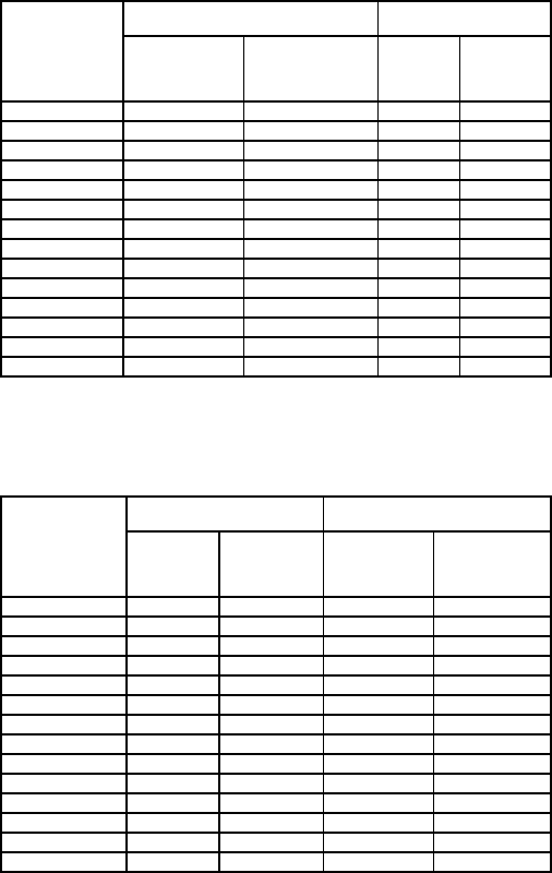
—38—
The suction and discharge pressure levels should now move
to their normal start-up levels.
NOTE: When the compressor is rotating in the wrong direc-
tion, the unit makes an elevated level of noise and does not
provide cooling.
IX. COOLING
Set space thermostat to OFF position. To start unit, turn on
main power supply. Set system selector switch at COOL posi-
tion and fan switch at AUTO. position. Adjust thermostat to
a setting below room temperature. Compressor, outdoor fan
and evaporator motor start on closure of contactor.
Check unit charge. Refer to Service, Refrigerant Charge sec-
tion, page 48.
Reset thermostat at a position above room temperature.
Compressor will shut off. Evaporator fan will shut off after
30-second delay.
To Shut Off Unit
Set system selector switch at OFF position. Resetting ther-
mostat at a position above room temperature shuts unit off
temporarily until space temperature exceeds thermostat
setting.
X. MAIN BURNERS
Main burners are factory set and should require no
adjustment.
TO CHECK ignition of main burners and heating controls,
move thermostat set point above room temperature and ver-
ify that the burners light and evaporator fan is energized.
After ensuring that the unit continues to heat the building,
lower the thermostat setting below room temperature and
verify that the burners and evaporator fan turn off. (Fan will
turn off only if fan selector switch is in the AUTO. position.)
Refer to Table 34A and 34B for the correct orifice to use at
high altitudes.
XI. HEATING
1. Purge gas supply line of air by opening union ahead
of gas valve. If gas odor is detected, tighten union and
wait 5 minutes before proceeding.
2. Turn on electrical supply and manual gas valve.
3. Set system switch selector at HEAT position and fan
switch at AUTO. or ON position. Set heating temper-
ature lever above room temperature.
4. The induced-draft motor will start.
5. After a call for heating, the main burners should light
within 5 seconds. If the burner does not light, then
there is a 22-second delay before another 5-second
try. If the burner still does not light, the time delay is
repeated. If the burner does not light within 15 min-
utes, there is a lockout. To reset the control, break the
24-v power to W1.
6. The evaporator-fan motor will turn on 45 seconds af-
ter the burners are ignited.
7. The evaporator-fan motor will turn off 45 seconds af-
ter thermostat temperature is satisfied.
8. Adjust airflow to obtain a temperature rise within
the range specified on the unit nameplate.
NOTE: The default value for the evaporator-fan motor ON/
OFF delay is 45 seconds. The Integrated Gas Unit Controller
(IGC) modifies this value when abnormal limit switch cycles
occur. Based upon unit operating conditions, the ON delay can
be reduced to 0 seconds and the OFF delay can be extended
to 180 seconds. When one flash of the LED is observed, the
evaporator-fan ON/OFF delay has been modified.
If the limit switch trips at the start of the heating cycle dur-
ing the evaporator ON delay, the time period of the ON delay
for the next cycle will be 5 seconds less than the time at
which the switch tripped. (Example: If the limit switch trips
at 30 seconds, the evaporator-fan ON delay for the next cycle
will occur at 25 seconds.) To prevent short-cycling, a 5-second
reduction will only occur if a minimum of 10 minutes has
elapsed since the last call for heating.
The evaporator-fan OFF delay can also be modified. Once the
call for heating has ended, there is a 10-minute period dur-
ing which the modification can occur. If the limit switch trips
during this period, the evaporator-fan OFF delay will
increase by 15 seconds. A maximum of 9 trips can occur,
extending the evaporator-fan OFF delay to 180 seconds.
To restore the original default value, reset the power to the
unit.
To Shut Off Unit
Set system selector switch at OFF position. Resetting heat-
ing selector lever below room temperature will temporarily
shut unit off until space temperature falls below thermostat
setting.
Table 34A — Altitude Compensation*— Standard Units
*As the height above sea level increases, there is less oxygen per cubic foot of air.
Therefore, heat input rate should be reduced at higher altitudes.
†Orifices available through your Bryant distributor.
Table 34B — Altitude Compensation*— Low NOx Units
*As the height above sea level increases, there is less oxygen per cubic foot of
air. Therefore, the input rate should be reduced at higher altitudes.
†Orifices are available through your local Bryant distributor.
ELEVATION
(ft)
74,000 AND 115,000 BTUH
NOMINAL INPUT
150,000 BTUH
NOMINAL INPUT
Natural
Gas
Orifice
Size†
Liquid
Propane
Orifice
Size†
Natural
Gas
Orifice
Size†
Liquid
Propane
Orifice
Size†
0-2,000 33 43 30 37
2,000 36 44 31 39
3,000 36 45 31 40
4,000 37 45 32 41
5,000 38 46 32 42
6,000 40 47 34 43
7,000 41 48 35 43
8,000 42 49 36 44
9,000 43 50 37 45
10,000 44 50 39 46
11,000 45 51 41 47
12,000 46 52 42 48
13,000 47 52 43 49
14,000 48 53 44 50
ELEVATION
(ft)
60,000 AND 90,000 BTUH
NOMINAL INPUT
120,000 BTUH
NOMINAL INPUT
Natural
Gas
Orifice
Size†
Liquid
Propane
Orifice
Size†
Natural
Gas
Orifice
Size
Liquid
Propane
Orifice
Size†
0-2,000 38 45 32 42
2,000 40 47 33 43
3,000 41 48 35 43
4,000 42 49 36 44
5,000 43 49 37 45
6,000 43 50 38 45
7,000 44 50 39 46
8,000 45 51 41 47
9,000 46 52 42 48
10,000 47 52 43 49
11,000 48 53 44 50
12,000 49 53 44 51
13,000 50 54 46 52
14,000 51 54 47 52
—39—
XII. SAFETY RELIEF
A soft solder joint at the suction service Schrader port pro-
vides pressure relief under abnormal temperature and pres-
sure conditions (i.e., fire in building).
XIII. VENTILATION (CONTINUOUS FAN)
Set fan and system selector switches at ON and OFF posi-
tions, respectively. Evaporator fan operates continuously to
provide constant air circulation. When the evaporator-fan
selector switch is turned to the OFF position, there is a
30-second delay before the fan turns off.
XIV. ECONOMI$ER+ CONTROLLER
The EconoMi$er+ controller is mounted to the top of the
EconoMi$er+ damper and is accessible by removing the filter
access door of the unit.
The EconoMi$er+ controller is protected by a sheet metal
enclosure mounted over the controller. Remove the single
screw on the front of the enclosure and lift off the top for
access to the controller. The primary purpose of the controller
is to provide control of the EconoMi$er+ dampers and the
cooling compression stages. The status of the indoor fan is
monitored through the G input but is not directly controlled
by the controller. The heating function is completely indepen-
dent of the controller.
IMPORTANT: The controller can only be used with conven-
tional thermostats with Y1, Y2 and G input to the controller;
it can NOT be used with electronic thermostats with a pro-
portional room temperature input, or with Variable Air Vol-
ume systems.
There are 4 LEDs on the controller, which are used to read
values and display status and configuration information.
There are 2 buttons (READ/ADJUST and ADVANCE/ MAN-
UAL), which change modes and configure the controller. See
Fig. 36.
The EconoMi$er+ microprocessor based control system pro-
vides the following control functions:
• EconoMi$er+ damper control for free cooling
• Minimum position control for ventilation
• Demand Ventilation Control using a CO2 sensor
• Compressor Cooling Stage Control
• Occupied/Unoccupied Control
• Diagnostics Display and History
• Manual test control
See Table 35 for Inputs and Outputs.
A. Integrated Display
The control board includes an integrated display, which is
used for the following functions:
•Configuration and setup
• Set point and control adjustment
• Error status and alarm monitoring
• Manual control
• Reading sensor values
There are 5 modes of display operation:
•Startup Mode
•Run Mode
• Read Mode
•Setup Mode
• Manual Mode
External devices are not required to operate and configure
the control.
B. Startup Mode
During the first 3 seconds after power is applied to the con-
trol, the four LEDs flash as shown in Table 36, indicating
that the control is being initialized. The buttons are not
operational during Startup mode.
C. Run Mode
Run mode indicates status of controller and unit. The mode
can be changed to the Read, Setup, or Manual modes by
pushing various buttons.
While the control is in Run mode, the DS1 heartbeat indica-
tor LED (red) will flash to indicate the controller is operating
properly. The DS2 Econo indicator LED (yellow) will flash
whenever economizer is being used for free cooling. The DS3
first stage cooling indicator LED (green) will be on steady
indicate demand for stage 1 cooling. The DS4 second stage
cooling indicator LED (green) will be on steady to indicate
demand for stage 2 cooling.
If the controller is in a different mode, the controller will
return to Run mode after 10 minutes of user inactivity or if
the READ/ADJUST (#1) and ADVANCE/MANUAL (#2) but-
tons are held for at least 3 seconds until all LEDs flash.
D. Read Mode
Read mode is used to check set points (Table 37) and I/O
channel status (Table 38). Enter the Read mode by pushing
and releasing the READ/ADJUST (#1) button. A user can
only enter Read mode from the Run mode (to get to Run
mode, press both the #1 and #2 buttons for at least 3 seconds
until all LEDs flash). In Read mode, LEDs are not lit until
the READ/ADJUST button (#1) is pushed.
NOTE: If the user pushes and holds the READ/ADJUST but-
ton (#1) for more than 3 seconds, then the control will go into
the Setup mode, indicated by the yellow LED (on steady).
While in Read mode, push button #1 then the DS1 LED
(Red) flashes to indicate setup point number as defined in
the setup table. The two green LEDs will then show the
value of the display item. The DS3 LED will first display the
tens digit and the DS4 LED will then display the ones digit.
For example to display 54, the DS3 LED will flash 1 group of
5 at a high flash rate to indicate 50, and then follow with
4 flashes (DS4) at 1-second intervals to complete the display
of the number 54.
NOTE: Do not try to count the “5 Fast Flashes” individually,
but instead count how many groups of 5 flashes were dis-
played. In this case, 1 group of 5 flashes, plus the 4 flashes at
1 second results in the value of 54.
To read the display again, push the READ/ADJUST (#1) but-
ton and the sequence will repeat as many times as needed.
To advance to the next setup point, push the ADVANCE/
MANUAL (#2) button. The controller will cycle through all
the setup channels (Table 37) and then the I/O channels
(Table 38) and then back to the first setup channel.
NOTE: The user can only advance forward, not reset to #1 or
go backwards. Cycling the EconoMi$er+ power will reset the
item number (but not the item value) to item #1.
In the Read mode for setup variables, the LEDs will not turn
on steady; the LEDs will always flash. Steady-on indicators
are reserved for the configuration modes. No data is modified
in the Read mode. The controller will always remain at the
last read number even if reset back to normal operation.
NOTE: To enter another mode, the user first must exit the
Read mode.
If no button is pushed in 10 minutes, Read mode will auto-
matically be exited. Also, if the READ/ADJUST (#1) and
ADVANCE/MANUAL (#2) buttons are pushed and held for
more than 3 seconds, then Read mode will be exited to Run
mode. While in the Read mode, the controller will continue to
operate with normal unit control.
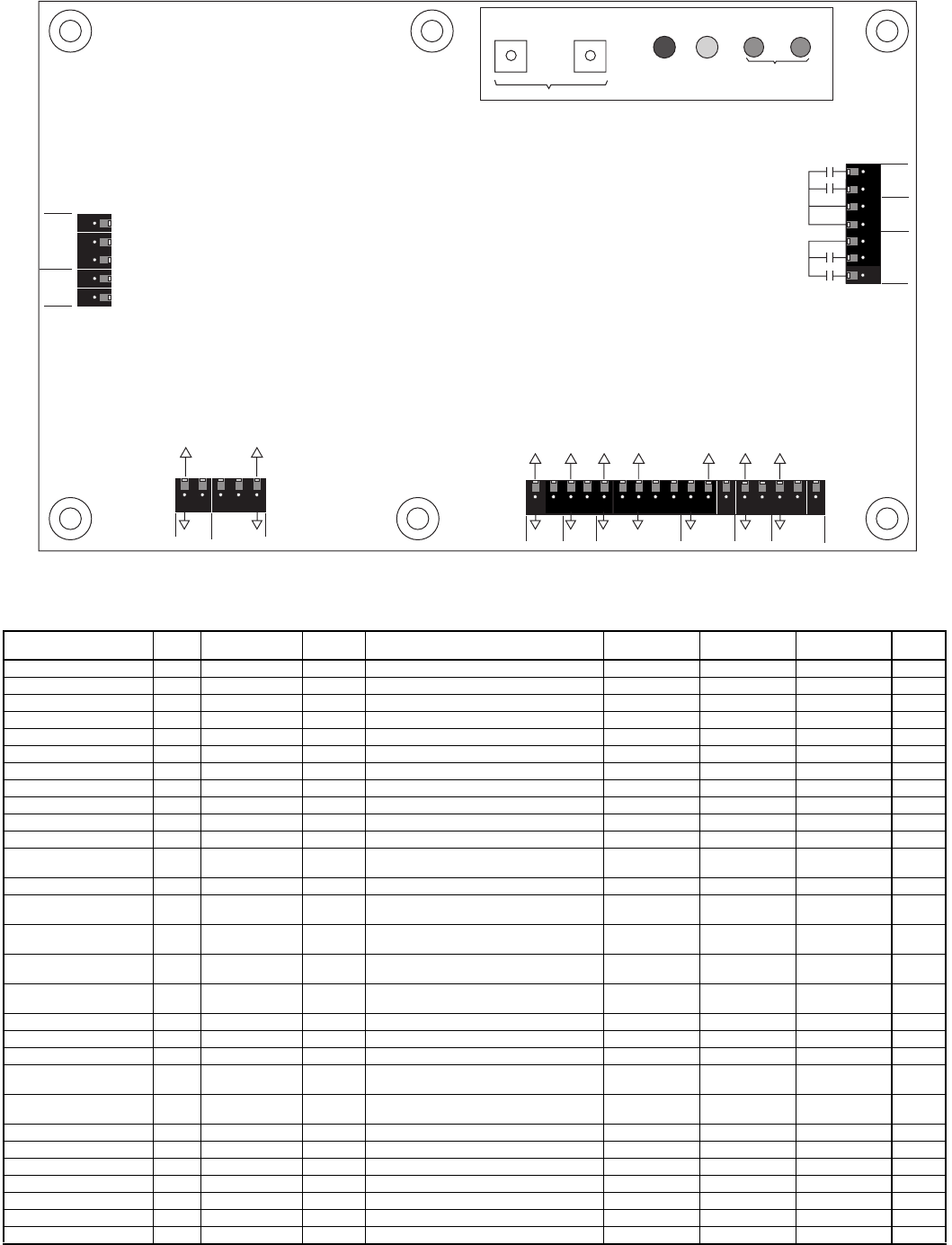
—40—
Table 35 — EconoMi$er+ Inputs and Outputs
*If there are 3 stages then there can only be 1 stage of power exhaust.
†If there are 4 stages then no power exhaust stages are directly controlled.
INPUT NAME TYPE USE INPUT/OUTPUT
RANGE
CONVERSION
RANGE
CONVERSION
RESOLUTION CONNECTION PIN
NO.
THERMOSTAT INPUTS
Y1 (Cool/Low Cool)Y1 Switch Standard 18-30 vac 50/60 Hz w/min 24 mA Load NA On/Off J1 1
Y2 (Cool 2/HighCool)Y2 Switch Option 18-30 vac 50/60 Hz w/min 24 mA Load NA On/Off J1 2
G(fan)G Switch Standard 18-30 vac 50/60 Hz w/min 24 mA Load NA On/Off J1 3
Occupied/Unoccupied OCC Switch Option 18-30 vac 50/60 Hz w/min 24 mA Load NA On/Off J1 4,5
POWER
Power 24V Input Standard 18-30 VAC 50/60 Hz NA NA J2 1,2
ECONOMIZER MOTOR
Control CNT 2-10 vdc Standard 2-10 vdc 0-100%1%J2 3,4,5
ANALOG INPUTS
Supply Air Temperature SAT 10 K Thermistor Standard 1816 to 86407 Ohms 30 to 125 F 0.8 F J3 1,2
Outside Air
Temperature OAT 10 K Thermistor Standard 1816 to 86407 Ohms 30 to 125 F 0.8 F J3 3,4
Return Air Temperature RAT 10 K Thermistor Option 1816 to 86407 Ohms 30 to 125 F 0.8 F J3 5,6
Indoor Humidity IRH 4-20 mA,
Loop Powered Option 4-20 mA, 24 vdc 0-100%.08 mA J3 7,8,9
Outdoor Humidity ORH 4-20 mA,
Loop Powered Option 4-20 mA, 24 vdc 0-100%.08 mA J3 10,11,1
2
Indoor CO2IAQ 4-20 mA,
Ext Sourced Option 4-20 mA, 24 vdc 0-200 PPM/10 10 PPM J3 13,14
Remote Minimum
Position Pot MIN 10K Option 10K to 100K Ohms 0 to 100%1%J3 15,16,1
7
RELAY OUTPUTS
Cooling Stage 1 CP1 Relay Standard 24 vac, 2.5 Amps at 24 vac NA On/Off J4 1,3,4
Cooling Stage 2 CP2 Relay Option 24 vac, 2.5 Amps at 24 vac NA On/Off J4 2,3,4
Power Exhaust 2/
Cooling Stage 3*
CP3/
EX2 Relay Option 24 vac, 2.5 Amps at 24 vac NA On/Off J4 5,6
Power Exhaust 1/
Cooling Stage 4†
CP4/
EX1 Relay Option 24 vac, 2.5 Amps at 24 vac NA On/Off J4 5,7
DISPLAY
Setpoint Switch1SP1 Digital Standard Open/Closed Logic Open/Closed On Board NA
Setpoint Switch2SP2 Digital Standard Open/Closed Logic Open/Closed On Board NA
LED 1 DS1 LED Output Standard Red Logic On/Off On Board NA
LED 2 DS2 LED Output Standard Yellow Logic On/Off On Board NA
LED 3 DS3 LED Output Standard Green Logic On/Off On Board NA
LED 4 DS4 LED Output Standard Green Logic On/Off On Board NA
Y1
Y2
G
OCC
24V
1J1
5
Y1 (cool 1)
Y2 (cool 2)
G (fan)
OCC
24 VAC
THERMOSTAT INPUTS
Occupied/unoccupied
I/O support dry circuit
contact (min 24 mA I)
POWER
SUPPLY
2-10 VDC
ECONOMIZER
CONTROL
J2
15
CNT
24V
24V
24 VAC
24 VAC
Control
SAT
OAT
RAT
IRH
VRF
ORH
VRF
IAQ
MIN
VRF
IAQ (4-20ma)
min (10K pot)
ORH (4-20 ma)
Vref
Vref
Vref
IRH (4-20 ma)
RAT (10k thermistor)
OAT (10k thermistor)
SAT (10k thermistor)
J3
117
ANALOG INPUTS
4-20 mA external powered between signal and ground
4-20 mA loop powered between 24 VDC and signal
Relays rated at 24 VAC 3A
and traces for 8A.
NOTE: For 1 and 2 stage
cooling, 2 stages of power
exhaust will be used.
For 3 cooling stages, only 1
stage of power exhaust will be
used, and for 4 stages no power
exhaust will be controlled
directly by the control.
OUTPUT RELAYS
C1
C2
24V
24V
24V
C3
C4
24 VAC
24 VAC
24 VAC
CP1
CP2
EX2/CP3
EX1/CP4
J4
READ/
ADJUST
ADVANCE
MANUAL DS1 DS2
SETPOINT DISPLAY
DS3 DS4
date or serial no RED YELLOW GREEN
PUSH BUTTONS
#1 #2
Fig. 36 — EconoMi$er+ Controller Board

—41—
Table36—Start-UpModeSequence
LED — Light-Emitting Diode
Table 37 — Configuration Variables (Read and Setup Modes)
LEGEND NOTE: The accessibility of these channels will be as follows:
READ MODE — All channels will be accessible.
SETUP MODE — Only channels 1-20 will be accessible and 20 will be used to
reset alarms.
Table38—Input/Output Channels
NOTE: The accessibility of these channels will be as follows:
READ MODE — All channels will be accessible for reading.
ADJUST MODE — Only channels 1-5 will be accessible.
MANUAL MODE — Only channels 1-5 will be accessible.
TIME LED 1/DS1 (RED)LED 2/DS2 (YELLOW)LED 3/DS3 (GREEN)LED 4/DS4 (GREEN)
0-1.0 SEC OFF OFF OFF OFF
1-1.5 SEC FLASH ½ SEC OFF OFF OFF
1.5-2.0 SEC OFF FLASH ½ SEC OFF OFF
2.0-2.5 SEC OFF OFF FLASH ½ SEC OFF
2.5-3.0 SEC OFF OFF OFF FLASH ½ SEC
NO. SETUP POINTS
(viewable and adjustable)UNITS MINIMUM
VALUE
MAXIMUM
VALUE
FACTORY
SETTING INC COMMENTS
1Supply Air Temperature Setpoint F 40 F 65 F 55 F 1 F Leaving Air Temperature Control Point
2Occupied Minimum Economizer
Position %Item 15 +1%100%15%1%Min Econo Position (occupied mode)
3Unoccupied Minimum Economizer
Position %1%100%5%1%Min Econo Position (unoccupied mode)
4Economizer Maximum Position %1%100%100%1%Maximum Econo Position
5Economizer Type — 1 3 2 1 1=Vent Only, 2 =Proportional,
3=3 Position
6Economizer Changeover Type — 1 5 2 1 1 =Switch, 2 =Outdoor Dry Bulb,
3=Diff Dry Bulb, 4 =Outdoor Enthalpy,
5=Diff Enthalpy
7Economizer Changeover Setpoint
(mode 2) F 45 F 70 F 65 F 1 F For Outdoor Changeover
8Economizer Changeover Setpoint
(mode 3)
— 1 4 1 1 Outdoor Enthalpy Changeover Setpoint
1=A, 2 =B, 3 =C, 4 =D
9No.ofcompressors — 1 4 2 1 1,2,3,or4
10 Compressor Sequencing — 1 4 1 1 1=DC-Sensible, 2 =DC-Latent,
3=LAT-Sensible, 4 =LAT-Latent
11 Power Exhaust Stage 1 Activation %1%Item 12 -5%25%1%Economizer Position
12 Power Exhaust Stage 2 Activation %Item 11 +1%100%50%1%Economizer Position (>stage 1)
13 Unoccupied Configuration — 1 3 3 1 1 =No Unoccupied Cooling,
2=Unoccupied Free Cooling,
3=Unoccupied Free &Mech Cooling
14 Compressor Lockout Temperature — 1 F 65 F 45 F 1 F Compressor Operation
15 IAQ Min Economizer Position
Setpoint %1%Item 2 +1%5%1%Min IAQ Position for VOC Emissions
16 IAQ Enable — 1 2 1 1 1 =Disabled, 2 =Enabled
17 Outdoor IAQ Reference PPM/10 1 PPM/10 100 PPM/10 40 PPM/10 1 PPM/10 Outdoor Reference IAQ Level
18 IAQ Lower Limit Control Point
Differential PPM/10 1 PPM/10 Item 19 -1
PPM/10 60 PPM/10 1 PPM/10 Differential Lower Limit Indoor
IAQ Level
19 IAQ Upper Limit Control Point
Differential PPM/10 Item 18 +1
PPM/10 200 PPM/10 140 PPM/10 1 PPM/10 Differential Upper Limit Indoor
IAQ Level
20 1st Most Recent Error/Reset — 1 8 — — Used in Setup Mode to Reset Alarms
21 2nd Most Recent Error (read only) — 1 8 — — Not Displayed in Setup Mode
22 3rd Most Recent Error (read only) — 1 8 — — Not Displayed in Setup Mode
23 4th Most Recent Error (read only) — 1 8 — — Not Displayed in Setup Mode
24 5th Most Recent Error (read only) — 1 8 — — Not Displayed in Setup Mode
DC — Direct Control
IAQ—Indoor Air Quality
LAT — Leaving Air Temperature Compensated Control
VOC — Volatile Organic Compounds
NO. I/O POINTS UNITS MINIMUM VALUE MAXIMUM VALUE INC COMMENTS
1C1 Output — Off On — Compressor 1
2C2 Output — Off On — Compressor 2
3C3 Output — Off On — Compressor 3/Power Exhaust 2
4C4 Output — Off On — Compressor 4/Power Exhaust 1
5Economizer Damper Output %1 F 100 F 1%Damper Commanded Position
6Supply Air Temperature F 1 F 150 F 1 F Supply Air Temperature
7Outdoor Air Temperature F 1 F 150 F 1 F Outdoor Air Temperature
8Return Air Temperature F 1 F 150 F 1 F Return Air Temperature
9Indoor Relative Humidity %1%100%1%Return Air Relative Humidity
10 Outdoor Relative Humidity %1%100%1%Outdoor Air Relative Humidity
11 Indoor Air Quality PPM 1 PPM/10 200 PPM/10 10 PPM Indoor Air Quality (/10)
12 Remote Minimum Position %1%100%1%Remote Minimum Pot Position
13 Y1 Status — Open Close — Thermostat Y1 Status
14 Y2 Status — Open Close — Thermostat Y2 Status
15 G Status — Open Close — Indoor Fan Status
16 Occ Status — Open Close — Remote Occupied Status
—42—
After advancing through all the configuration variables in
the Read mode, the controller will then advance through the
status of the I/O channels. As in the Read mode, there will be
no LEDs on. Push the READ/ADJUST (#1) button and the
yellow LED will flash the “I/O Point” number and the green
LEDs will flash the “I/O Values” in the same manner
described in the Read mode section. See Table 38. At the first
I/O point (Compressor 1 Output), the DS2 LED (Yellow) will
flash with the number of the I/O channel and the DS1 LED
(red) will stop flashing. This will be followed by the I/O chan-
nel status. To read the value again, push the READ/ADJUST
(#1) button.
To advance to the next channel, push the ADVANCE/MAN-
UAL (#2) button. If the number of the channel or the status
value is greater than 4 the controller will count out the
increments of 5 at a high flash rate followed by the remain-
ing digits. The channel number will be counted out through
the DS2 LED (yellow). The status value will be counted out
through the DS3 and DS4 LEDs (green).
If the status value is an analog value then the numeric value
will be displayed by using the DS3 Green LED to display the
tens digit and the DS4 will be used to display the ones digit.
If the channel is a digital output (relay), the DS3 LED (flash-
ing green) will indicate ON status and the DS4 LED (flash-
ing green) will indicate OFF status. If the output is the
economizer control signal then the DS3 LED will be used to
indicate the motor is being driven open, and the DS4 LED
will be used to indicate it is being closed. If the motor is not
being commanded in either direction then both the DS3 and
DS4 LEDs will be on. The controller will first go through the
output relays, then the economizer motor, and will then fol-
low with the values currently being read for the analog input
channels as defined in the configuration table. All values are
maintained in memory even during a power loss. To exit
Setup mode, push and hold the READ/ADJUST (#1) and
ADVANCE/MANUAL (#2) buttons for more than 3 seconds.
Setup mode will automatically be exited after 10 minutes of
no activity.
E. Setup Mode
The Setup mode is used to change set points and configura-
tion values.
Enter the Setup mode by pushing and holding the READ/
ADJUST (#1) button 1 for at least 3 seconds until all LEDs
flash once. Then, the yellow LED will come on steady. A user
can only enter the Setup mode from the Run mode (to get to
Run mode, press buttons both buttons #1 and #2 for at least
3 seconds).
In Setup mode, all configurations can be modified even while
the unit is running, but the user will not be able to adjust the
I/O channels. Only channels 1 through 20 on Table 37 will be
accessible in the Setup mode. Channel 20 will be used to
reset any alarms that may have occurred. As an option,
alarms can also be reset by cycling power to the controller.
NOTE: During the Setup mode, all routines including safety
routines will continue to run and control the unit.
While in this mode, the DS1 LED (red) will flash to indicate
the number of the configuration item. The DS2 LED (yellow)
will be on continuously to indicate that the unit is in configu-
ration mode. Use the ADVANCE/MANUAL button to
sequence through the setup channels. If the value of the
channel is less than 5 it will count out the value of the chan-
nel on the DS1 LED at 1-second intervals. If the channel
value is 5 or greater, the DS1 LED will first count out the
groups of 5 and then following with the remaining digit.
Verify what Setup Point is being read by pushing the READ/
ADJUST button (#1). First the Red LED will flash the set
point number, then the Green LEDs will flash the value.
Then, the green DS3 and DS4 LEDs will each come on
steady for about 2 seconds. While DS3 is on steady, its new
value can be entered by pushing READ/ADJUST (#1), and
entering the value for the ten’s digit. When the DS4 comes
on steady, enter the value for the one's digit. After the green
LEDs are off, push the READ/ADJUST button (#1) again to
verify that the correct value has been entered. If the configu-
ration is a discrete On/off setting, push the READ/ADJUST
button (#1) to toggle LED 3 or 4 on or off.
Setup Example 1: Change “Occupied Minimum Position”
(configuration item 2) to 53%.
1. Read the General Notes about reading and entering
values found on the label on the top of the
EconoMi$er+.
2. Push and hold button #1 (READ/ADJUST) for at
least 3 seconds until all LEDs flash. The yellow LED
will go on steady.
3. Read the current configuration point by pushing but-
ton #1. The red LED flashes the configuration point
number and the green LEDs flash the current setting
for that setup point number.
4. On the label (on top of the EconoMi$er+), read Step 2
and Note 1 for Setup mode operation.
5. Use button #2 (ADVANCE/MANUAL) to advance to
configuration point number 2, Occupied Min.
NOTE: Before performing Step 6, be ready to push button
#1; there is a limited time window that can easily be missed
when the DS3 green LED comes on, and again when the DS4
green LED comes on.
6. Verify the configuration point by pushing button #1.
The red LED should flash twice to indicate point 2,
and then the green LEDs will flash the current
setting.
7. Next, the green DS3 LED will turn on steady for 2
seconds. During this time, push button #1 five times.
8. The DS3 LED will turn off and the green DS4 LED
will go on steady for 2 seconds. During this time,
push button #1 three times.
9. The 5 button #1 pushes, followed by the 3 button #1
pushes is the sequence that sets the occupied mini-
mum position to 53%.
10. Wait until the green LEDs turn off then verify the
setting by pushing button #1 to read the value. There
should be 5 fast blinks of DS3 and 3 slow blinks of
DS4.
Setup Example 2: Change the Occupied Minimum Position
(item 2) to 2% (lowest value).
1. Read the General Notes about reading and entering
values found on the label on the top of the
EconoMi$er+.
2. Push and hold button #1 (READ/ADJUST) for at
least 3 seconds until all LEDs flash. The yellow LED
will go on steady.
3. Read the current configuration point by pushing but-
ton #1. The red LED flashes the configuration point
number and the green LEDs flash the current setting
for that setup point number.
4. On the label (on top of the EconoMi$er+), read Step 2
and Note 1 for Setup mode operation.
5. Use button #2 (ADVANCE/MANUAL) to advance to
configuration point number 2, Occupied Min.
—43—
6. Verify the configuration point by pushing button #1.
The red LED should flash twice to indicate point 2,
and then the green LEDs will flash the current
setting.
NOTE: Since the occupied minimum position MUST
be 1 greater than the IAQ minimum position (item
15), the IAQ minimum position must be changed
first. (IAQ min has a default value of 5%, which is
higher than the 2% value in this example.)
7. Use button #2 (ADVANCE/MANUAL) to get to config-
uration point 15 (IAQ Minimum Position).
NOTE: Before performing Step 8, be ready to push button
#1; there is a limited time window that can easily be missed
when the DS3 green LED comes on, and again when the DS4
green LED comes on.
8. Verify the configuration point by pushing button #1.
The red LED should flash 15 times to indicate point
15, then the green LEDs will flash the current
setting.
9. Next, the green DS3 LED will turn on steady for 2
seconds. During this time, do NOT do anything so
that the position defaults to 0.
10. The DS3 LED will turn off and the green DS4 LED
will go on steady for 2 seconds. During this time,
push button #1 once to set the point to 1%.
11. Wait until the green LEDs turn off then verify the
setting by pushing button #1 to read the value. DS3
should not blink, and DS4 should blink once.
12. Now configure the Occupied Minimum Position to
2%. Use button #2 (ADVANCE/MANUAL) to get to
configuration point 2.
NOTE: Before performing Step 13, be ready to push button
#1; there is a limited time window that can easily be missed
when the DS3 green LED comes on, and again when the DS4
green LED comes on.
13. Verify the configuration point by pushing button #1.
The red LED should flash twice to indicate point 2,
then the green LEDs will flash the current setting.
14. Next, the green DS3 LED will turn on steady for 2
seconds. During this time, do NOT do anything so
that the position goes to 0.
15. The DS3 LED will turn off and the green DS4 LED
will go on steady for 2 seconds. During this time,
push button #1 twice to set the point to 2%.
16. Wait until the green LEDs turn off then verify the
setting by pushing button #1 to read the value. DS3
should not blink, and DS4 should blink twice.
NOTE: Configuration items 2, 15, 11, 12, 18 and 19 (in
Table 37) are dependent upon other items. Before attempt-
ing to change one of these items, be sure to check the value of
the item it depends upon (as described in Example 2 above).
IMPORTANT: During SETUP MODE, changes are allowed
when the DS3 LED and DS4 LED are lit for 2 seconds (as
described in Example 1 and 2 above). During this time, if
button #1 is pushed to change one position and not the other,
the value for that one position will change and the other will
default to zero (unless a dependency prevents the zero). How-
ever, if button #1 is not pushed at all during the 2 seconds
that the green LEDs are lit, the configuration item will not
change.
F. Manual Mode
Manual mode is used to control the status of I/O channels for
use in troubleshooting. See Table 38.
Enter the Manual mode by holding down the ADVANCE/
MANUAL (#2) button for at least 3 seconds until all LEDs
flash and then the red LED comes on steady.
NOTE: A user can only enter the Manual mode from the
RUN mode, which is entered by pushing buttons #1 and #2
for at least 3 seconds.
All EconoMi$er+ control outputs are turned off. “I/O
Inputs” 1-5 can be adjusted even if the unit is in operation.
In manual mode, the yellow DS2 LED flashes once to indi-
cate the I/O channel. See Table 38. If the value is less than 5,
the yellow DS2 LED will count out the value using 1-second
flashes. If the value is greater than 4, the yellow DS2 LED
will count out groups of 5 at a high flash rate and then follow
with the additional value at a flash rate of once per
second. For example a flash of 1 indicates Compressor Relay
Output 1.
Push READ/ADJUST button (#1) to read the value. The yel-
low LED will flash the I/O Channel number being viewed.
Once the channel number is displayed it will then turn on
the appropriate green LED (DS3 or DS4) to indicate the sta-
tus of the output. For relay outputs if the DS3 LED is on,
then the output is on. If DS4 is on, then the output is off. The
green DS3 and DS4 LEDs will remain on for about 2 seconds
and if during this time the READ/ADJUST (#1) button is
pushed, then the output will toggle to the alternate state. To
change again, push the READ/ADJUST button and repeat
the test or change the status of the output. As an example,
for channel 5 (EconoMi$er+ control damper motor) use the
READ/ADJUST button to toggle the motor from open to
close in %.
At any time, the ADVANCE/MANUAL (#2) button can be
used to advance to the next SET I/O. To exit the mode, push
and hold the READ/ADJUST and ADVANCE/MANUAL but-
tons (#1 and #2) for more than 3 seconds.
NOTE: After exiting the Manual mode, the controller will
re-initialize and start with all outputs off.
G. Error Mode
The error mode is used to indicate that an error has occurred
The error is indicated by LED #1 red and #2 yellow are on
steady.
Enter the RUN mode by pushing the READ/ADJUST and
ADVANCE/MANUAL buttons (#1 and #2) for at least
3 seconds until all LEDs flash. Next, push and release but-
ton #1 to enter the Read mode. Then push button #2 to
advance to item 20 (“first most recent error”). Determine the
error by reading the value in items 20 to 24 and referring to
the Troubleshooting section.
One the error has been fixed, press buttons #1 and 2 for at
least 3 seconds to exit Read mode. All LEDs will flash.
Enter Setup mode by pressing the READ/ADJUST button
(#1) for at least 3 seconds. All LEDs will flash. Push the
ADVANCE/MANUAL button (#2) to advance to item 20.
Push READ/ADJUST to read item 20.
To reset the error code while the green DS4 LED is on, press
the READ/ADJUST button (#1) once. In addition to resetting
the error mode, this will erase all error codes. Cycling the
power will also erase the error code.
XV. ECONOMI$ER+ CONFIGURATION
For most applications, the factory setting will be used to con-
trol the EconoMi$er+. However, there are 19 different vari-
ables that can be used to configure the control for wide range
of applications. The factory settings and variables are shown
in Table 37.

—44—
IMPORTANT: There is no way to reset/restore the factory
default configurations; use caution when making changes to
any set point or operational variable.
The EconoMi$er+ control accepts an occupied/unoccupied
switch input. This input is used to control the occupied
and unoccupied minimum ventilation damper position as
shown in Table 37 items 2 (ECONOMIN_SP) and 3
(U_ECONOMIN_SP). These values represent the minimum
damper position. In addition, the controls allows for different
modes of compressor operation in the unoccupied mode.
Using item 13 in Table 37 (OCC_MODE), the user can select
one of the following unoccupied modes:
• No unoccupied cooling
• Unoccupied free cooling (EconoMi$er+)
• Unoccupied free cooling and mechanical cooling
The EconoMi$er+ will control the cooling operation of the
unit based on the demand from the thermostat outputs Y1
and Y2. The EconoMi$er+ will monitor the fan output G, but
will not control the fan directly. Note that G must be ener-
gized for any cooling to take place. Gas or electric heating
will be controlled directly from the thermostat.
When a demand for cooling occurs, the control will check to
see if it is in the occupied or unoccupied mode. Depending on
the configuration, the control will move the outside air
damper to the ventilation position. If the outside air condi-
tions are acceptable, then the control will use the
EconoMi$er+ for free cooling. If the supply air temperature
does not meet the configurable set point, then the control
will turn on additional stages of mechanical cooling. Several
compressor sequences can be used depending on the applica-
tion requirements; these will be covered in the mechanical
compressor staging section.
A. Compressor Configuration and Control
The EconoMi$er+ control can support from 1 to 4 compressor
stages. For the 3 to 12 1/2 ton units, there will only be 1 or
2 stages of compressor cooling, so the control is factory
configured for 2 stages. There is no difference between 1 and
2 stages. The control also provides the option to configure for
high sensible or high latent loads, but for units with only two
compressors this option does not apply.
Compressors are configured using item 10 (STAGE_TYPE)
in Table 37. The control also has the capability of controlling
directly to Y1 and Y2 inputs. The control can be configured
to control to the leaving air temperature using Y1 and Y2 as
a low cool and high cool demand based on the supply air set
point and the rate of change of supply air temperature. For
low cool the leaving air temperature set point will be
SAT_SP+2° F. For high cool the leaving air temperature set
point will be the supply air temperature set point (SAT_SP).
To use this option, configure the compressor sequencing vari-
able (STAGE_TYPE) to a value of 3. Configure the supply air
temperature set point (SAT_SP) to the desired leaving-air
temperature.
NOTE: The supply air temperature set point is also the tem-
perature used for EconoMi$er+ control.
The logic will control the operation of the compressors
depending on the configuration selected. If free cooling can
be used, then the compressors will be integrated with the
EconoMi$er+ to provide the lowest cost cooling control. The
logic includes time guards on the compressors to provide a
minimum of 3 minutes on and 3 minutes off time. The con-
trol will also prevent two compressors from starting at the
same time. The logic uses the EconoMi$er+ to prevent rapid
cycling of the compressors and low air temperatures.
B. Ventilation Air and Free Cooling
In order for the EconoMi$er+ to control ventilation air and
free cooling, several items must be configured.
EconoMi$er+ Type
First, select the EconoMi$er+ control type that will be used.
This is the EconoMi$er+ Type function (ECONO_TYPE)
defined by item 5 in Table 37. The choices are:
1. Vent only — This is used to have just ventilation con-
trol. The EconoMi$er+ will not provide free cooling,
but the occupied and unoccupied minimum positions
can be used.
2. Proportional — In this configuration, full proportion-
al EconoMi$er+ control will be used. When
EconoMi$er+ free cooling cannot be used, the damp-
ers will be set to the appropriate occupied and unoc-
cupied minimum positions.
3. Three-Position — This mode of EconoMi$er+ is used
to provide a minimum ventilation EconoMi$er+ posi-
tion and a fixed free cooling or high ventilation posi-
tion. The high ventilation position is controlled by the
optional Remote EconoMi$er+ Enable Switch Input
connected to terminals 11 and 12 on T3.
Supply Air Temperature Set Point
Once the type of EconoMi$er+ control has been selected, the
user will need to set the Supply Air Temperature set point
(SAT_SP). The SAT_SP has a range of 40 to 65 F.
NOTE: This will be the set point when both Y1 and Y2 are
closed. When just Y1 is closed, the set point will be 2 F
higher.
Minimum Damper Position
Set the occupied minimum damper position
(ECONOMIN_SP) and unoccupied minimum position
(U_ECONOMIN_SP). These should be set to provide the
ventilation requirements at full occupancy as defined by the
building specifications. When demand ventilation is used,
the control will close the dampers below this position based
on measured CO2 levels in the space to provide additional
operation savings.
The control will also allow for the use of a remote minimum
position potentiometer. This will only adjust the Occupied
Minimum position. If used, the software set point
ECONOMIN_SP should be set to 0 as the control will use the
largest set point.
The damper position is not linear with the amount of outside
air, so the user will need to set the position of the
EconoMi$er+ accordingly. It is best to use the following equa-
tion and measured data to set the position:
OA = % outdoor air
SAT = supply air temperature
RAT = return air temperature
OAT = outdoor air temperature
The SAT and OAT values can be read from the control and, if
the unit is equipped with an RAT sensor, then all three val-
ues can be read. For the calculation to work properly, there
should be at least a 10° F difference between the OAT and
RAT temperatures.
Maximum Damper Position
Set the maximum EconoMi$er+ position. Normally this is
set at 100%. If using 3-position control or there is a reason
not to use 100% outside air, this can be set using the
EconoMi$er+ Maximum Position (MAX_POS_SP).
OA = SAT – RAT *100
OAT – RAT

—45—
Compressor Lockout Temperature
Set the Compressor Lockout Temperature. The Compressor
Lockout Temperature (CMP_LOCK) is used to prevent com-
pressor from running at low ambient conditions when an
EconoMi$er+ can easily satisfy the load.
EconoMi$er+ Changeover Control
Determine the type of EconoMi$er+ changeover control
which will be used to enable and disable free cooling. This is
done using the EconoMi$er+ Changeover Type.
1. Switch — This changeover setting is used when a
remote signal from an energy management system
will enable and disable the EconoMi$er+. This is
done through a remote EconoMi$er+ enable switch.
2. Outdoor Dry Bulb — For this changeover setting, the
EconoMi$er+ will be enabled based on the outside-air
temperature. The EconoMi$er+ is shipped with an
outside air temperature sensor. The outside air tem-
perature set point can be configured by the user. The
EconoMi$er+ will be disabled when the outdoor-air
temperature rises above the set point. The configura-
tion variable is the EconoMi$er+ Changeover set
point (OAT_SP).
3. Differential Dry Bulb — For this changeover setting,
the EconoMi$er+ will be enabled whenever the out-
side-air temperature is lower than the return-air
temperature. No configuration of set points is re-
quired other than to select the differential dry bulb
function.
4. Outdoor Enthalpy — For this changeover setting, the
control will enable the EconoMi$er+ based on the
outside-air enthalpy curves as shown in Fig. 29. Us-
ing the EconoMi$er+ Changeover set point
(ENTHALPY_SP), select curves A, B, C or D.
The control will then use the EconoMi$er+ at condi-
tions below the curve. The control uses the OAT and
optional humidity sensor to calculate the enthalpy
and also has the A, B, C, and D curves stored in
memory.
5. Differential Enthalpy — For this changeover setting,
the EconoMi$er+ will be enabled based on the com-
parison of the enthalpy of the return air and outside
air. If the outside air enthalpy is lower than the re-
turn air, then the EconoMi$er+ will be enabled. To
use this option, an accessory outside air humidity
sensor, a return air dry bulb sensor and a return air
humidity sensor must be ordered and installed. No
configuration of set points is required other than to
select the function.
C. Demand Ventilation Configuration
The EconoMi$er+ control has demand ventilation control
capability when using an IAQ sensor. The indoor air quality
(IAQ) is measured using a CO2 sensor. The IAQ sensor can
be field-installed in the return duct or the occupied space.
The EconoMi$er+ control algorithm modulates the position
of the EconoMi$er+ damper between two user configurations
depending upon the relationship between the IAQ and the
Outdoor Air Quality (OAQ). The lower of these two positions
is referred to as the Minimum IAQ Minimum EconoMi$er+
Position (IAQMIN_SP).
The higher position is referred to as the Occupied
EconoMi$er+ Minimum Position (ECONOMIN_SP). The
IAQMIN_SP should be set to an EconoMi$er+ position that
brings in enough fresh air to remove contaminants and CO2
generated by sources other than people. The
ECONOMIN_SP should be set to an EconoMi$er+ position
that brings in enough fresh air to remove contaminants and
CO2 generated by all sources including people at the design
value for maximum occupancy.
A reference differential CO2 level above the outside CO2
level is used as the starting point for IAQ control and
another reference differential level for maximum ventilation
at design occupancy is used for the end of IAQ control.
Between these points the control will modulate the dampers
open from the IAQMIN_SP and the ECONOMIN_SP set-
points. The damper position will never go above
ECONOMIN_SP or below IAQMIN_SP.
The control does not measure the outdoor IAQ reference
level as these levels are relatively constant. The installer
should take a measurement at start-up of the unit and enter
this value into the control using the Outdoor Air IAQ refer-
ence level configuration.
The control is configured for air quality sensors which pro-
vide 4 mA at 0 ppm and 20 mA at 2000 ppm. If a sensor has
a different range, these bounds must be reconfigured.
To configure the control for an IAQ sensor perform the fol-
lowing steps:
1. Determine the Occupied EconoMi$er+ Minimum
position (ECONOMIN_SP) and enter it into the
control.
2. Determine the IAQ minimum EconoMi$er+ position
(IAQMIN_SP) and enter it into the control.
3. Enable IAQ control using IAQ Enable (IAQ_FLG).
4. Determine the Outdoor Air IAQ Reference (OAQ) and
enter it into the control.
NOTE: The value entered into the control will be the
CO2 ppm level divided by 10. For example, 400 ppm
would be entered as 40.
5. Determine the lower control point differential level
(DAQLO) and enter it into the control. This is a dif-
ferential level so if the desired level to start IAQ con-
trol is 500 ppm and the OAQ reference level is 400
then a value of 100 would be used.
NOTE: The value entered into the control will be the
CO2 ppm level divided by 10. For example 100 ppm
would be entered as 10.
6. Determine the upper control point differential level
(DAQHI) and enter it into the control. This is a differ-
ential level so if the desired level to start IAQ control
is 1100 ppm and the OAQ reference level is 400 then
a value of 700 would be used.
NOTE: The value entered into the control will be the
CO2 ppm level divided by 10. For example 700 ppm
would be entered as 70.
D. Power Exhaust Configuration
The EconoMi$er+ can control up to 2 stages of power
exhaust. Power exhaust activation is done through config-
urable damper position set points. The first stage of power is
controlled by relay C4 on the EconoMi$er+ board. The acti-
vation point for the first stage is set using the Power
Exhaust Stage 1 Activation set point (PE_SP1). The second
stage of power exhaust must be set at a value greater than
the first stage. It is configured using the Power Exhaust
Stage 2 Activation set point (PE_SP2).
XVI. OPERATING SEQUENCE
A. Cooling, Units without EconoMi$er+
When thermostat calls for cooling, terminals G and Y1 and
the compressor contactor (C) are energized. The indoor
(evaporator) fan motor (IFM), compressor, and outdoor (con-
denser) fan motor (OFM) start. The OFM runs continuously

—46—
while the unit is in cooling. When the thermostat is satisfied,
C is deenergized and the compressor and OFM shut off. After
a 30-second delay, the (IFM) shuts off. If the thermostat fan
selector switch is in the ON position, the evaporator motor
will run continuously.
B. Heating, Units without EconoMi$er+
When the thermostat calls for heating, terminal W1 is ener-
gized. The induced-draft motor is energized and the burner
ignition sequence begins. The indoor (evaporator) fan motor
(IFM) is energized 45 seconds after a flame is ignited. When
additional heat is needed, W2 is energized and the high-fire
solenoid on the main gas valve (MGV) is energized. When
the thermostat is satisfied and W1 is deenergized, the IFM
stops after a 45-second time-off delay.
C. Cooling, Units withEconoMi$er+
For EconoMi$er+ operation, there must be a thermostat call
for the fan (G). This will move the damper to its minimum
position.
When the EconoMi$er+ control is the occupied mode and a
call for cooling exists (Y1 on the thermostat), the control will
first check for indoor fan operation. If the fan is not on, then
cooling will not be activated. If the fan is on, then the control
will open the EconoMi$er+ damper to the minimum position.
On the initial power to the EconoMi$er+ board, it will take
the damper up to 21/2 minutes before it begins to position
itself. With subsequent fan signal (G) to the board, the
changed in damper position will take up to 30 seconds to ini-
tiate. Damper movement from full closed to full open (or vice
versa) will take 21/2 minutes.
If the damper is in the process of a change (for example going
to 100% open) and the signal (G) is turned off, the damper
will continue to open to 100% before it closes (due to no fan
signal [G]).
If free cooling can be used as determined from the appropri-
ate changeover command (switch, dry bulb, enthalpy curve,
differential dry bulb, or differential enthalpy), then the con-
trol will modulate the dampers open to main the supply air
temperature set point plus 2° F.
If there is a further demand for cooling (cooling second stage
— Y2 is energized), then the control set point for the leaving
air will be set at the supply air set point to increase the cool-
ing capacity. If this cannot satisfy the load then the control
will bring on compressor stages as needed to maintain the
supply air temperature set point. The EconoMi$er+ damper
will be locked open at 100% or the maximum damper posi-
tion set point.
To ensure that there is oil return, the compressors will
operate for at least 3 minutes. If, during this period, the leav-
ing temperature drops below the set point by 5 F, then the
EconoMi$er+ dampers will be closed to 60% until the com-
pressor is turned off to avoid cold leaving air temperatures.
If the conditions are not suitable for free cooling then the
EconoMi$er+ dampers will be closed to the minimum venti-
lation position.
Compressor stages will be used to cool the air. If the control
is configured for direct control by Y1 and Y2, then the stages
will sequence based on the demand of Y1 and Y2. If the
control is configured for leaving air temperature control,
then Y1 will maintain the leaving air temperature at the
supply air set point plus 2° F. If Y1 and Y2 are closed, then
the leaving air will be controlled to the supply air set point.
If Y2 is closed and Y1 is open, then control will shut down
and indicate an error due to a thermostat failure or improper
wiring of the thermostat.
If the unit is in the unoccupied mode, then the control of the
temperature will depend on the unoccupied free cooling
configuration: no unoccupied cooling, unoccupied free cooling
with any mechanical cooling, or unoccupied free and
mechanical cooling. If free cooling is enabled, then the con-
trol will check if free cooling can be used. The EconoMi$er+
will then control to the leaving air temperature set point
plus 2 F for a Y1 command, or the leaving air temperature
set point for a Y1 and Y2 command. If mechanical cooling is
allowed to be used, then the control will then bring on addi-
tional stages of mechanical cooling if free cooling cannot sat-
isfy the load.
If the EconoMi$er+ control:
• is in the occupied mode
• is configured to use demand ventilation
• cannot use free cooling
• has return air or space CO2 levels below the DAQLO
limit,
then the EconoMi$er+ damper position will be set to the
IAQMIN_SP set point. If the CO2 level rises above the
DAQLO limit, then the dampers will modulate open in a lin-
ear relationship until the return air or space CO2 levels are
at or above the DAQHIGH limit. The damper position will be
at the ECONOMIN_SP set point.
When the EconoMi$er+ is being used for free cooling and the
position exceeds the power exhaust set point, then the con-
trol will turn on the appropriate power exhaust fans. Refer to
Fig. 23 for barometric relief capacity, Fig. 24 for outdoor air
leakage, and Fig. 25 for pressure drop.
Unoccupied and Occupied Minimum Position Control
There is an unoccupied minimum damper position and an
occupied minimum damper position on the EconoMi$er+
controller. When the HVAC fan is off the outdoor air damper
will always be closed. When the fan is on and in the unoccu-
pied mode, the outdoor air damper will be at the unoccupied
minimum position. When the fan is on (G call) and in the
occupied mode, the outdoor air damper will be at the occu-
pied minimum position.
A jumper wire is factory-installed to force the unit into
occupied configuration whenever G or Y1 are closed. Without
the jumper wire, the unit will always be in unoccupied mode.
The 2 minimum position settings are also used in the IAQ
sequence of operation. See Indoor Air Quality Sensor on
page 18.
NOTE: The minimum position signal takes priority over the
maximum position signal. If the maximum damper position
is set below the minimum damper position, the EconoMi$er+
controller will maintain the actuator at minimum position.
Adjust the unoccupied minimum position to allow the mini-
mum amount of outdoor air, as required by local codes, to
enter the building. Make minimum position adjustments
with at least 10 F (6 C) temperature difference between the
outdoor and return air temperatures.
To determine the unoccupied minimum position setting, per-
form the following procedure:
Calculate the appropriate supply-air temperature using the
following formula: (TO x OA) + (TR x RA) = TM
TO = Outdoor-Air Temperature
OA = Percent of Outdoor Air
TR = Return-Air Temperature
RA = Percent of Return Air
TM = Supply-Air Temperature
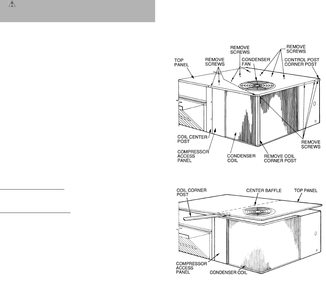
—47—
As an example, if local codes require 10% outdoor air during
occupied conditions, outdoor-air temperature is 60 F, and
return-air temperature is 75 F:
(60 x 0.10) + (75 x 0.90) = 73.5 F
Carefully adjust the unoccupied minimum position until the
measured supply-air temperature matches the calculated
value. Then, carefully adjust the occupied minimum position
set point on the controller until the desired position is
reached.
D. Heating, Units withEconomi$er+
When the room temperature calls for heat through terminal
W1, the indoor (evaporator) fan contactor (IFC) and heater
contactor no. 1 (HC1) are energized. On units equipped for
2 stages of heat, when additional heat is needed, W2 is ener-
gized and the high-fire solenoid on the main gas valve (MGV)
is energized. The economizer damper moves to the minimum
position. When the thermostat is satisfied, the damper
moves to the fully closed position.
SERVICE
I. CLEANING
Inspect unit interior at the beginning of heating and cooling
season and as operating conditions require.
A. Evaporator Coil
1. Turn unit power off and install lockout tag. Remove
evaporator coil access panel.
2. If economizer or two-position damper is installed,
remove economizer by disconnecting Molex plug and
removing mounting screws.
3. Slide filters out of unit.
4. Clean coil using a commercial coil cleaner or dish-
washer detergent in a pressurized spray canister.
Wash both sides of coil and flush with clean water.
For best results, back-flush toward return-air section
to remove foreign material. Flush condensate pan
after completion.
5. Reinstall economizer and filters.
6. Reconnect wiring.
7. Replace access panels.
B. Condenser Coil
Inspect coil monthly. Clean condenser coil annually, and as
required by location and outdoor air conditions.
One-Row Coils (Size 036)
Wash coil with commercial coil cleaner. It is not necessary to
remove top panel.
2-Row Coils (Sizes 048-073)
Clean coil as follows:
1. Turn off unit power and install lockout tag.
2. Remove top panel screws on condenser end of unit.
3. Remove condenser coil corner post. See Fig. 37. To
hold top panel open, place coil corner post between
top panel and center post. See Fig. 38.
4. Remove screws securing coil to compressor plate and
compressor access panel.
5. Remove fastener holding coil sections together at re-
turn end of condenser coil. Carefully separate the
outer coil section 3 to 4 in. from the inner coil section.
See Fig. 39.
6. Use a water hose or other suitable equipment to flush
down between the 2 coil sections to remove dirt and
debris. Clean the outer surfaces with a stiff brush in
the normal manner.
7. Secure inner and outer coil rows together with a field-
supplied fastener.
8. Reposition the outer coil section and remove the coil
corner post from between the top panel and center
post. Reinstall the coil corner post and replace all
screws.
C. Condensate Drain
Check and clean each year at start of cooling season. In win-
ter, keep drain dry or protect against freeze-up.
D. Filters
Clean or replace at start of each heating and cooling season,
or more often if operating conditions require it. Replacement
filters must be same dimensions as original filters.
E. Outdoor-Air Inlet Screen
Clean screen with steam or hot water and a mild detergent.
Do not use disposable filters in place of screen.
CAUTION: When servicing unit, shut off all electri-
cal power to unit and install lockout tag to avoid shock
hazard or injury from rotating parts.
Fig. 37 — Cleaning Condenser Coil
Fig. 38 — Propping Up Top Panel
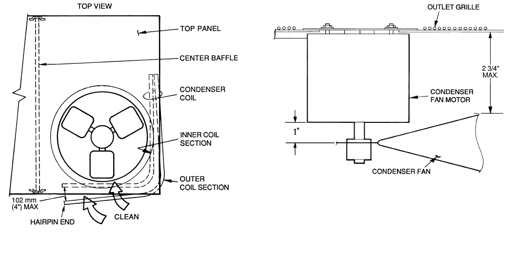
—48—
II. LUBRICATION
A. Compressors
Each compressor is charged with the correct amount of oil at
the factory.
B. Fan Motor Bearings
Fan motor bearings are of the permanently lubricated type.
No further lubrication is required. No lubrication of con-
denser or evaporator fan motors is required.
III. BLOWER BELT ADJUSTMENT
Inspect blower belt for wear, proper belt tension, and pulley
alignment as conditions require or at the beginning of each
heating and air conditioning season.
Refer to Step 9 — Adjust Evaporator-Fan Speed on page 24
for adjustment and alignment procedures.
Check belt tension at least once each heating or cooling sea-
son or as conditions require. Adjust as required.
IV. MANUAL OUTDOOR-AIR DAMPER
If outdoor-air damper blade adjustment is required, see
Manual Outdoor-Air Damper section on page 14.
V. ECONOMI$ER+ ADJUSTMENT
Refer to Optional EconoMi$er+ section on page 15.
VI. CONDENSER-FAN ADJUSTMENT (Fig. 40)
Shut off unit power supply. Remove condenser-fan assembly
(grille, motor, and fan) and loosen fan hub setscrews. Adjust
fan height as shown in Fig. 40. Tighten setscrews and
replace condenser-fan assembly.
VII. REFRIGERANT CHARGE
Amount of refrigerant charge is listed on unit nameplate
(also refer to Table 1). Compressor must run a minimum of
10 minutes before adjusting or checking charge.
Unit panels must be in place when unit is operating during
charging procedure.
A. No Charge
Use standard evacuating techniques. After evacuating sys-
tem, to 500 microns, weigh in the specified amount of refrig-
erant. (Refer to Table 1.)
B. Low-Charge Cooling
Using Cooling Charging Charts, Fig. 41-44, vary refrigerant
until the conditions of the appropriate chart are met. Note
the charging charts are different from type normally used.
Charts are based on charging the units to the correct super-
heat for the various operating conditions. Accurate pressure
gage and temperature sensing device are required. Do not
use pocket type thermometers for measuring surface temper-
atures as they are not designed for this type of measure-
ment. Connect the pressure gage to the service port on the
suction line. Mount the temperature sensing device on the
suction line and insulate it so that outdoor ambient tempera-
ture does not affect the reading. Indoor-air cfm must be
within the normal operating range of the unit.
C. To Use Cooling Charging Chart
Take the outdoor ambient temperature and read the suction
pressure gage. Refer to chart to determine what suction tem-
perature should be. If suction temperature is high, add
refrigerant. If suction temperature is low, carefully recover
some of the charge. Recheck the suction pressure as charge
is adjusted.
EXAMPLE: (Fig. 43)
Outdoor Temperature . . . . . . . . . . . . . . . . . . . . . . . . . . . 85 F
Suction Pressure . . . . . . . . . . . . . . . . . . . . . . . . . . . . . .80 psig
Suction Temperature should be . . . . . . . . . . . . . . . . . . . 76 F
(Suction Temperature may vary 5 F.)
VIII. FLUE GAS PASSAGEWAYS
To inspect the flue collector box and upper areas of the heat
exchanger:
1. Remove the combustion blower wheel and motor
assembly according to directions in Combustion-Air
Blower section on page 49.
2. Remove the flue cover to inspect the heat exchanger.
3. Clean all surfaces as required using a wire brush.
Fig. 39 — Separating Coil Sections
Fig. 40 — Condenser-Fan Adjustment
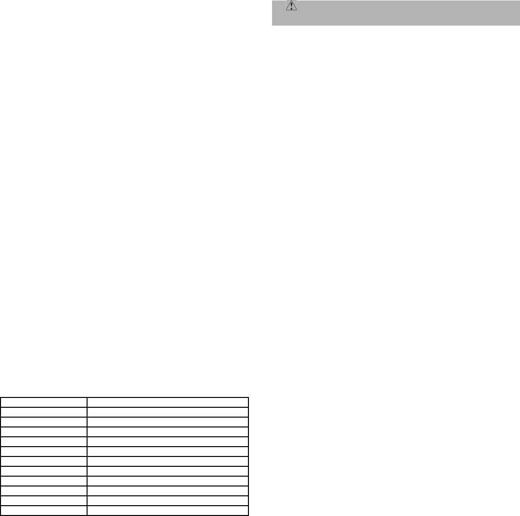
—49—
IX. COMBUSTION-AIR BLOWER
Clean periodically to assure proper airflow and heating effi-
ciency. Inspect blower wheel every fall and periodically during
heating season. For the first heating season, inspect blower
wheel bimonthly to determine proper cleaning frequency.
To access burner section, slide the sliding burner partition
out of the unit.
To inspect blower wheel, shine a flashlight into draft hood
opening. If cleaning is required, remove motor and wheel as
follows:
1. Slide burner access panel out.
2. Remove the 7 screws that attach induced-draft motor
housing to vestibule plate (Fig. 45).
3. The blower wheel can be cleaned at this point. If ad-
ditional cleaning is required, continue with Steps 4
and 5.
4. To remove blower from the motor shaft, remove 2
setscrews.
5. To remove motor, remove the 4 screws that hold the
motor to mounting plate. Remove the motor cooling
fan by removing one setscrew. Then remove nuts that
hold motor to mounting plate.
6. To reinstall, reverse the procedure outlined above.
X. LIMIT SWITCH
Remove blower access panel (Fig. 7). Limit switch is located
on the fan deck.
XI. BURNER IGNITION
Unit is equipped with a direct spark ignition 100% lockout
system. Integrated Gas Unit Controller (IGC) is located in the
control box (Fig. 11). The IGC contains a self-diagnostic LED
(light-emitting diode). A single LED on the IGC provides a
visual display of operational or sequential problems when the
power supply is uninterrupted. When a break in power occurs,
the IGC will be reset (resulting in a loss of fault history) and
the indoor (evaporator) fan ON/OFF times will be reset. The
LED error code can be observed through the viewport. During
servicing refer to the label on the control box cover or Table 39
for an explanation of LED error code descriptions.
If lockout occurs, unit may be reset by interrupting power
supply to unit for at least 5 seconds.
Table 39 — LED Error Code Description*
LEGEND
LED — Light-Emitting Diode
*A 3-second pause exists between LED error code flashes. If more than one error
code exists, all applicable codes will be displayed in numerical sequence.
†Indicates a code that is not an error. The unit will continue to operate when this
code is displayed.
IMPORTANT: Refer to Troubleshooting Tables 41-43 for additional information.
XII. MAIN BURNERS
To access burners, remove burner access panel and slide out
burner partition. At the beginning of each heating season,
inspect for deterioration or blockage due to corrosion or other
causes. Observe the main burner flames and adjust, if
necessary.
A. Removal and Replacement of Gas Train (Fig. 45-47)
1. Shut off manual gas valve.
2. Shut off power to unit and tag disconnect.
3. Slide out burner partition.
4. Disconnect gas piping at unit gas valve.
5. Remove wires connected to gas valve. Mark each
wire.
6. Remove ignitor wires and sensor wires at the Inte-
grated Gas Unit Controller (IGC) (see Fig. 11).
7. Remove the 2 screws that attach the burner rack to
the vestibule plate (Fig. 45).
8. Slide the burner tray out of the unit (Fig. 46).
9. To reinstall, reverse the procedure outlined above.
B. Cleaning and Adjustment
1. Remove burner rack from unit as described in
Removal and Replacement of Gas Train section, above.
2. Inspect burners; if dirty, remove burners from rack.
3. Using a soft brush clean burners and cross-over port
as required.
4. Adjust spark gap. See Fig. 47.
5. Reinstall burners on rack.
6. Reinstall burner rack as described in Removal and
Replacement of Gas Train section, above.
XIII. HIGH-PRESSURE SWITCH
Located on the compressor hot gas line is a high-pressure
switch containing a Schrader core depressor. This switch
opens at 428 psig and closes at 320 psig. No adjustment is
necessary. Refer to Table 1.
XIV. LOSS OF CHARGE SWITCH
Located on the condenser liquid line is a low-pressure switch
which functions as a loss-of-charge switch. This switch con-
tains a Schrader core depressor. This switch opens at 7 psig
and closes at 22 psig. No adjustment is necessary. Refer to
Table 1.
XV. FREEZESTAT
Located on the “hair pin” end of the evaporator coil is a
bimetal temperature sensing switch. This switch protects
the evaporator coil from freeze-up due to lack of airflow. The
switch opens at 30 F and closes at 45 F. No adjustment is
necessary. Refer to Table 1.
XVI. REPLACEMENT PARTS
A complete list of replacement parts may be obtained from
any Bryant distributor upon request.
LED INDICATION ERROR CODE DESCRIPTION
ON Normal Operation
OFF Hardware Failure
1Flash†Evaporator Fan On/Off Delay Modified
2Flashes Limit Switch Fault
3Flashes Flame Sense Fault
4Flashes 4 Consecutive Limit Switch Faults
5Flashes Ignition Lockout Fault
6Flashes Induced-Draft Motor Fault
7Flashes Rollout Switch Fault
8Flashes Internal Control Fault
9Flashes Internal Software Processor Fault
CAUTION: When working on gas train, do not hit or
plug orifice spuds.
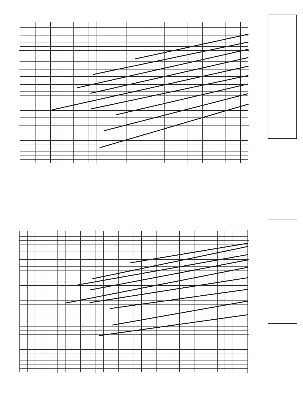
—50—
4 TON UNIT CHARGING CHART
30
40
50
60
70
80
90
100
20 30 40 50 60 70 80
SUCTION LINE TEMPERATURE (DEG. F)
207
276
345
414
483
552
621
689
-7 -1 4 10162127
SUCTION LINE TEMPERATURE (DEG. C)
OUTDOOR
TEMP
FC
125 52
115 46
105 41
95 35
85 29
75 24
65 18
55 13
45 7
SUCTION LINE PRESSURE (KILOPASCALS)
SUCTION LINE PRESSURE (PSIG)
Fig. 41 — Cooling Charging Chart, 580F036
Fig. 42 — Cooling Charging Chart, 580F048
30
40
50
60
70
80
90
100
20 30 40 50 60 70 80
SUCTION LINE TEMPERATURE (DEG. F)
207
276
345
414
483
552
621
689
-7 -1 4 10162127
SUCTION LINE TEMPERATURE (DEG. C)
3 TON UNIT CHARGING CHART
SUCTION LINE PRESSURE (PSIG)
SUCTION LINE PRESSURE (KILOPASCALS)
OUTDOOR
TEMP
FC
125 52
115 46
105 41
95 35
85 29
75 24
65 18
55 13
45 7
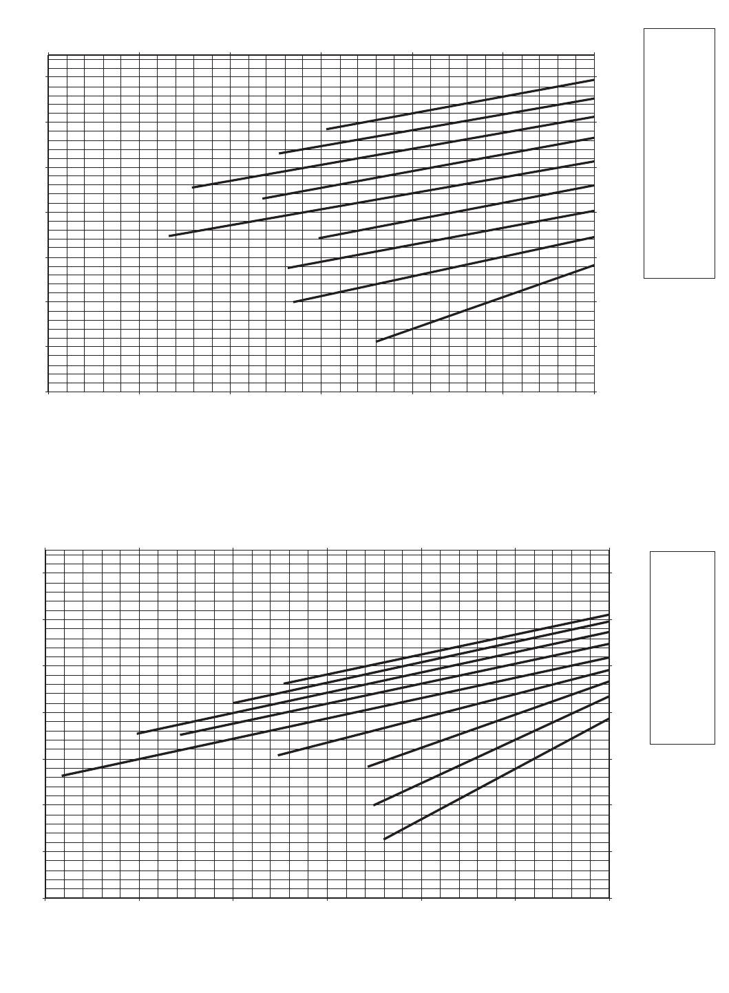
—51—
5 TON UNIT CHARGING CHART
30
40
50
60
70
80
90
100
20 30 40 50 60 70 80
SUCTION LINE TEMPERATURE (DEG. F)
207
276
345
414
483
552
621
689
-7 -1 4 10 16 21 27
SUCTION LINE TEMPERATURE (DEG. C)
OUTDOOR
TEMP
FC
125 52
115 46
105 41
95 35
85 29
75 24
65 18
55 13
45 7
SUCTION LINE PRESSURE (PSIG)
SUCTION LINE PRESSURE (KILOPASCALS)
30
40
50
60
70
80
90
100
20 30 40 50 60 70 80
SUCTION LINE TEMPERATURE (DEG. F)
207
276
345
414
483
552
621
689
-7 -1 4 10 16 21 27
SUCTION LINE TEMPERATURE (DEG. C)
OUTDOOR
TEMP
FC
125 52
115 46
105 41
95 35
85 29
75 24
65 18
55 13
45 7
6 TON UNIT (60 Hz) CHARGING CHART
SUCTION LINE PRESSURE (PSIG)
SUCTION LINE PRESSURE (KILOPASCALS)
Fig. 43 — Cooling Charging Chart, 580F060
Fig. 44 — Cooling Charging Chart, 580F072, 073
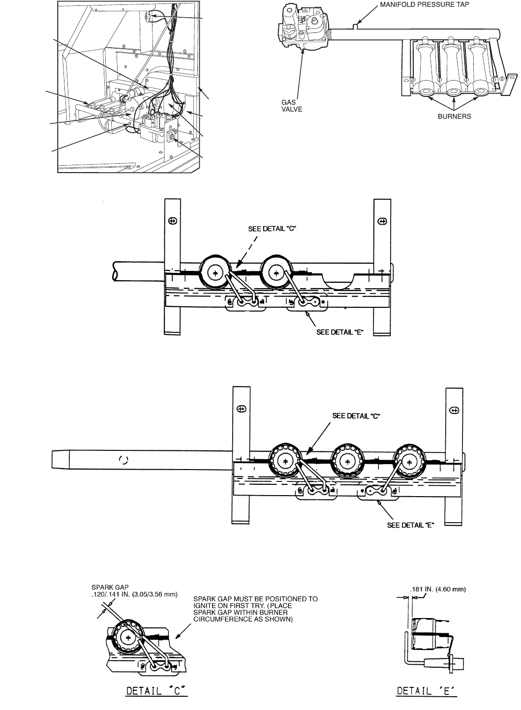
—52—
Fig. 46 — Burner Tray Details
Fig. 47 — Spark Adjustment
LOW HEAT
580F036-073 — 74,000 BTUH INPUT
580F036-060 (Low NOx) — 60,000 BTUH INPUT
MEDIUM AND HIGH HEAT
580F036-073 — 115,000 BTUH INPUT
580F048-073 — 150,000 BTUH INPUT
580F036-060 (Low NOx) — 90,000 BTUH INPUT
580F048-060 (Low NOx) — 120,000 BTUH INPUT
INDUCED-
DRAFT
MOTOR
MOUNTING
PLATE
INDUCED-
DRAFT
MOTOR
MANIFOLD
PRESSURE
TAP
VESTIBULE
PLATE
FLUE
EXHAUST
ROLLOUT
SWITCH
BLOWER
HOUSING
GAS
VALVE
BURNER
SECTION
Fig. 45 — Burner Section Details

—53—
TROUBLESHOOTING
I. ECONOMI$ER+ TROUBLESHOOTING
The EconoMi$er+ control has built-in diagnostics. The con-
trol can detect and display 10 different diagnostic codes as
shown in Table 40. The user can also use the integrated dis-
play to check the status of all the inputs and outputs and run
the manual control mode to check the operation of the
EconoMi$er+ and compressors.
Table 40 — EconoMi$er+ Error Codes
LEGEND
*If there is a RAM failure DS1+DS3/DS2+DS4 will alternately flash.
†If there is a ROM failure DS1+DS2/DS3+DS4 will alternately flash.
A. Error Code 1 — SAT Sensor Failure
Error Criteria
An SAT Sensor Failure error will occur if the sensor is
shorted or faulty. If the measured temperature reads below
–40 F or above 250 F an error will occur.
Required Action
If an error occurs, then the control will default to Mode 2
compressor stage control where Y1 and Y2 have direct con-
trol of the compressors. Use of free cooling is disabled and
the EconoMi$er+ will be set to the minimum damper posi-
tion for either the occupied or unoccupied mode of operation.
Replace sensor if faulty.
Reset Method
The error will automatically reset after the value has
returned to a normal level. The alarm has to be cleared from
the display in the Setup mode or a power reset.
B. Error Code 2 — RAT Sensor Failure
Error Criteria
The RAT Sensor failure error is only applicable the unit
has been configured for EconoMi$er+ changeover methods
3 (differential dry bulb) or 5 (differential humidity). For
other modes it should be ignored. If the sensor is shorted or
faulty, then the measured temperature will be below –40 F
or above 250 F and the error will occur.
Required Action
If this error occurs, then change the default EconoMi$er+
changeover control to method 2 (dry bulb changeover con-
trol) or replace sensor.
Reset Method
This error will automatically reset after the value has
returned to a normal level. The alarm will have to be cleared
from the display in the Setup mode.
C. Error Code 3 — OAT Sensor Failure
Error Criteria
An OAT Sensor Failure error occurs if the sensor is shorted
or faulty, then the measured temperature will be below
–40 F or above 250 F.
Required Action
If this error occurs disable the economizer and set the econo-
mizer to the minimum economizer position.
Reset Method
This error should automatically reset after the value has
returned to a normal level. The alarm will have to be cleared
from the display in the Setup mode or by a power reset.
D. Error Code 4 — ORH (Outdoor Relative Humidity)Sen-
sor Failure
Error Criteria
If the unit is configured for economizer changeover type 3 or
4, and the input signal is less than 2 mA or greater than
22 mA, then the sensor is faulty and an error will occur.
Required Action
If this error occurs, switch the EconoMi$er+ to dry bulb
changeover control.
Reset Method
This error should automatically reset after the value has
returned to a normal level. The alarm will have to be cleared
from the display in the Setup mode or by a power reset.
E. Error Code 5 — IRH (Indoor Relative Humidity)Sensor
Failure
Error Criteria
This error occurs if the unit is configured for EconoMi$er+
changeover type 5 and the input signal is less than 2 mA or
greater than 22 mA (faulty sensor).
Required Action
If this error occurs, switch the EconoMi$er+ to differential
dry bulb changeover control.
Reset Method
This error should automatically reset after the value has
returned to a normal level. The alarm will have to be cleared
from the display in the Setup mode or by a power reset.
F. Erro r C ode 6 — I AQSensor Failure
Error Criteria
This error occurs if the unit is configured for IAQ demand
ventilation control and the input signal is less than 2 mA or
greater than 22 mA (faulty sensor).
Required Action
If this error occurs, disable the IAQ control routine and
default to the standard EconoMi$er+ minimum position.
Reset Method
This error should automatically reset after the value has
returned to a normal level. The alarm will have to be cleared
from the display in the Setup mode or by a power reset.
G. ErrorCode7—Y2onWithY1 Off
Error Criteria
This error occurs if Y2 is turned on and Y1 is off. This indi-
cates that there is a wiring error at the thermostat connec-
tions. This alarm should be ignored for the first 20 seconds of
operation so that it does not conflict with the special produc-
tion test mode.
Required Action
Shut the unit off and check wiring.
NO. DESCRIPTION CRITERIA
1SAT Sensor Failure Temperature <–40 F or Greater Than 250 F
2RAT Sensor Failure Temperature <–40 F or Greater Than 250 F
3OAT Sensor Failure Temperature <–40 F or Greater Than 250 F
4ORH Sensor Failure Read Less Than 2 mA or Greater Than 22 mA
5IRH Sensor Failure Read Less Than 2 mA or Greater Than 22 mA
6IAQ Sensor Failure Read Less Than 2 mA or Greater Than 22 mA
7Y2OnY1 Off Wiring Error
8Micro Fails E2 Tests Hardware/Software Check
*Micro Fails RAM Test Hardware/Software Check
†Micro Fails ROM Tests Hardware/Software Check
IAQ—Indoor Air Quality
IRH — Indoor Relative Humidity
OAT — Outdoor Air Temperature
ORH — Outdoor Relative Humidity
RAT — Return Air Temperature
SAT — Supply Air Temperature

—54—
Reset Method
This error must be manually reset and requires a power
reset.
H. Error Code 8 — E2 Test Failure
Error Criteria
This error occurs if internal hardware detects an E2 failure.
Required Action
Shut the unit off.
Reset Method
This error must be manually reset and requires a power
reset.
I. Error Mode
When an error occurs, the red and yellow LEDs both come on
steady. To determine the error, follow these steps:
1. Enter the Run mode by pushing buttons #1 and #2 for
at least 3 seconds until all LEDs flash.
2. Press and release the #1 button to enter the Read
mode.
3. Push the ADVANCE/MANUAL (#2) button to ad-
vance to item number 20, “1st Most Recent Error.”
Determine the error(s) by reading the values in
items 20-24 and referring to the error codes described
above.
4. Fix the error(s).
5. Press buttons 1 and 2 to exit read mode. Enter Setup
mode by pressing button #1 for at least 3 seconds un-
til all the LEDs flash.
6. Push button #2 to advance to item number 20.
7. To reset the error code while the green DS4 LEDS is
ON, press the READ/ADJUST (#1) button once. This
resets the error mode and erases all repaired error
codes.
NOTE: Cycling power to the board will also erase the
repaired error codes.
J. RAM Test Failure
Error Criteria
If internal hardware detects a RAM failure, this alarm will
be displayed by alternately flashing DS1+DS3 and
DS2+DS4.
Required Action
Shut the unit off.
Reset Method
This error must be manually reset and requires a power
reset.
K. ROM Test Failure
Error Criteria
If internal hardware detects a ROM failure, the alarm is dis-
played by alternately flashing DS1+DS2 and DS3+DS4.
Required Action
Shut the unit off.
Reset Method
This error must be manually reset and requires a power
reset.
L. Unit Always in Unoccupied Mode
A jumper wire is factory-installed to force the unit into occu-
pied configuration whenever G or Y1 are closed. Without the
jumper wire, the unit will always be in unoccupied mode.
Check the wire. An occupied/unoccupied switch may be
installed in place of the jumper. Check the wiring and setting
of the switch.
II. UNIT TROUBLESHOOTING
Refer to Tables 41-43.
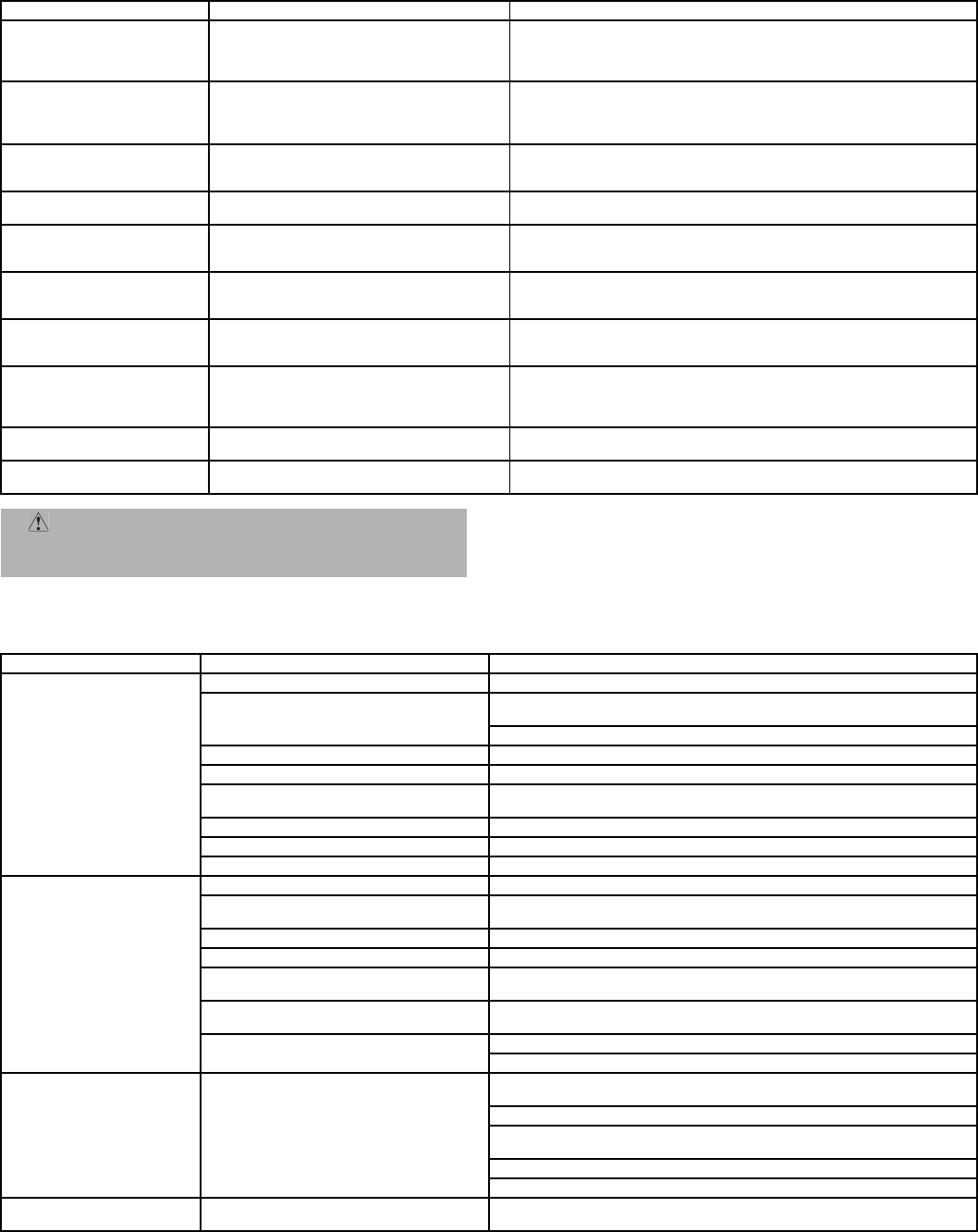
—55—
Table41—LEDErrorCodeServiceAnalysis
IMPORTANT: Refer to Table 42 — Heating Service Analysis for additional
troubleshooting analysis.
LEGEND
Table 42 — Heating Service Analysis
SYMPTOM CAUSE REMEDY
Hardware Failure.
(LED OFF)
Loss of power to control module (IGC). Check 5 amp fuse on IGC, power to unit, 24-v circuit breaker, and
transformer. Units without a 24-v circuit breaker have an internal overload
in the 24-v transformer. If the overload trips, allow 10 minutes for automatic
reset.
Fan ON/OFF Delay Modified
(LED/FLASH)
High limit switch opens during heat exchanger
warm-up period before fan-on delay expires.
Limit switch opens within three minutes after
blower-off delay timing in Heating mode.
Ensure unit is fired on rate and temperature rise is correct.
Ensure unit’s external static pressure is within application guidelines.
Limit SwitchFault.
(LED 2 flashes)
High temperature limit switch is open. Check the operation of the indoor (evaporator) fan motor.
Ensure that the supply-air temperature rise is in accordance with the range
on the unit nameplate.
Flame Sense Fault.
(LED 3 flashes)
The IGC sensed flame that should not be
present.
Reset unit. If problem persists, replace control board.
4ConsecutiveLimit
SwitchFaults.
(LED 4 flashes)
Inadequate airflow to unit. Check operation of indoor (evaporator) fan motor and that supply-air
temperature rise agrees with range on unit nameplate information.
Ignition Lockout.
(LED 5 flashes)
Unit unsuccessfully attempted ignition for
15 minutes.
Check ignitor and flame sensor electrode spacing, gaps, etc.
Ensure that flame sense and ignition wires are properly terminated. Verify
that unit is obtaining proper amount of gas.
Induced-Draft Motor Fault.
(LED 6 flashes)
IGC does not sense that induced-draft
motor is operating.
Check for proper voltage. If motor is operating, check the speed sensor
plug/IGC Terminal J2 connection. Proper connection: PIN 1 — White, PIN
2 — Red, PIN 3 — Black.
Rollout SwitchFault.
(LED 7 flashes)
Rollout switch has opened. Rollout switch will automatically reset, but IGC will continue to lockout unit.
Check gas valve operation. Ensure that induced-draft blower wheel is prop-
erly secured to motor shaft.
Reset unit at unit disconnect.
Internal Control Fault.
(LED 8 flashes)
Microprocessor has sensed an error in the
software or hardware.
If error code is not cleared by resetting unit power, replace the IGC.
Internal Software Fault.
(LED 9 flashes)
Internal Software Processor fault. Fault code will automatically reset after one hour. Can be immediately
reset by resetting unit power supply.
CAUTION: If the IGC must be replaced, be sure to ground
yourself to dissipate any electrical charge that may be present before
handling new control board. The IGC is sensitive to static electricity
and may be damaged if the necessary precautions are not taken. IGC — Integrated Gas Unit Controller
LED — Light-Emitting Diode
PROBLEM CAUSE REMEDY
Burners Will Not Ignite. Misaligned spark electrodes. Check flame ignition and sensor electrode positioning. Adjust as needed.
No gas at main burners. Check gas line for air, purge as necessary. After purging gas line of air, allow
gas to dissipate for at least 5 minutes before attempting to relight unit.
Check gas valve.
Water in gas line. Drain water and install drip leg to trap water.
No power to furnace. Check power supply, fuses, wiring, and circuit breaker.
No 24 v power supply to control circuit. Check transformer. Transformers with internal overcurrent protection require a
cool down period before resetting.
Miswired or loose connections. Check all wiring and wire nut connections.
Burned-out heat anticipator in thermostat. Replace thermostat.
Broken thermostat wires. Run continuity check. Replace wires, if necessary.
Inadequate Heating. Dirty air filter. Clean or replace filter as necessary.
Gas input to unit too low. Check gas pressure at manifold. Clock gas meter for input. If too low, increase
manifold pressure, or replace with correct orifices.
Unit undersized for application. Replace with proper unit or add additional unit.
Restricted airflow. Clean filter, replace filter, or remove any restrictions.
Blower speed too low. Use high speed tap, increase fan speed, or install optional blower, as suitable
for individual units.
Limit switch cycles main burners. Check rotation of blower, thermostat heat anticipator settings, and temperature
rise of unit. Adjust as needed.
Too much outdoor air. Adjust minimum position.
Check economizer operation.
Poor FlameCharacteristics. Incomplete combustion (lack of combustion
air) results in:
Aldehyde odors, CO, sooting flame, or floating
flame.
Check all screws around flue outlets and burner compartment. Tighten as nec-
essary.
Cracked heat exchanger.
Overfired unit — reduce input, change orifices, or adjust gas line or manifold
pressure.
Check vent for restriction. Clean as necessary.
Check orifice to burner alignment.
Burners Will Not Turn Off. Unit is locked into Heating mode for a one
minute minimum.
Wait until mandatory one minute time period has elapsed or re-
set power to unit.

—56—
Table 43 — Cooling Service Analysis
PROBLEM CAUSE REMEDY
Compressor and Condenser Fan
Will Not Start.
Power failure. Call power company.
Fuse blown or circuit breaker tripped. Replace fuse or reset circuit breaker.
Defective thermostat, contactor, transformer, or
control relay.
Replace component.
Insufficient line voltage. Determine cause and correct.
Incorrect or faulty wiring. Check wiring diagram and rewire correctly.
Thermostat setting too high. Lower thermostat setting below room temperature.
Compressor Will Not Start But
Condenser Fan Runs.
Faulty wiring or loose connections in compressor
circuit.
Check wiring and repair or replace.
Compressor motor burned out, seized, or internal
overload open.
Determine cause. Replace compressor.
Defective run/start capacitor, overload, start relay. Determine cause and replace.
One leg of three-phase power dead. Replace fuse or reset circuit breaker. Determine cause.
Compressor Cycles (Other Than
Normally Satisfying Thermostat).
Refrigerant overcharge or undercharge. Recover refrigerant, evacuate system, and recharge to
nameplate.
Defective compressor. Replace and determine cause.
Insufficient line voltage. Determine cause and correct.
Blocked condenser. Determine cause and correct.
Defective run/start capacitor, overload, or start relay. Determine cause and replace.
Defective thermostat. Replace thermostat.
Faulty condenser-fan motor or capacitor. Replace.
Restriction in refrigerant system. Locate restriction and remove.
Compressor Operates
Continuously.
Dirty air filter. Replace filter.
Unit undersized for load. Decrease load or increase unit size.
Thermostat set too low. Reset thermostat.
Low refrigerant charge. Locate leak;repair and recharge.
Leaking valves in compressor. Replace compressor.
Air in system. Recover refrigerant, evacuate system, and recharge.
Condenser coil dirty or restricted. Clean coil or remove restriction.
Excessive Head Pressure. Dirty air filter. Replace filter.
Dirty condenser coil. Clean coil.
Refrigerant overcharged. Recover excess refrigerant.
Air in system. Recover refrigerant, evacuate system, and recharge.
Condenser air restricted or air short-cycling. Determine cause and correct.
Head Pressure Too Low. Low refrigerant charge. Check for leaks;repair and recharge.
Compressor valves leaking. Replace compressor.
Restriction in liquid tube. Remove restriction.
Excessive Suction Pressure. High head load. Check for source and eliminate.
Compressor valves leaking. Replace compressor.
Refrigerant overcharged. Recover excess refrigerant.
Suction Pressure Too Low. Dirty air filter. Replace filter.
Low refrigerant charge. Check for leaks;repair and recharge.
Metering device or low side restricted. Remove source of restriction.
Insufficient evaporator airflow. Increase air quantity. Check filter and replace if
necessary.
Temperature too low in conditioned area. Reset thermostat.
Outdoor ambient below 25 F. Install low-ambient kit.
Evaporator Fan Will Not Shut Off. Time off delay not finished. Wait for 30-second off delay.
Compressor Makes Excessive
Noise (580F072 and 073 Scroll
Only).
Compressor rotating in wrong direction. Reverse the 3-phase power leads as described in the
Start-Up section on page 37.
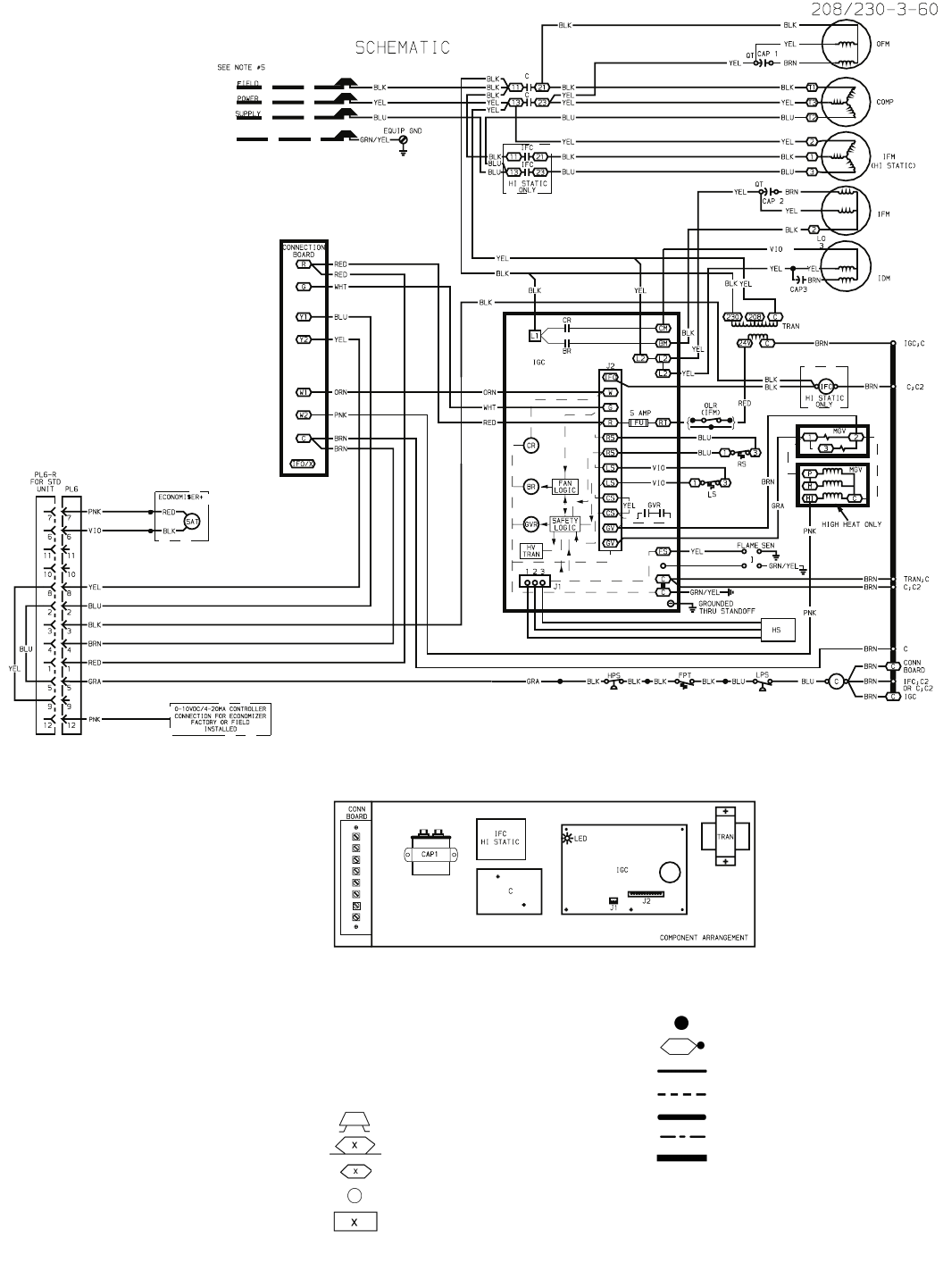
—57—
Fig. 48 — Typical Unit Wiring Diagram
LEGEND
OFM — Outdoor (Condenser) Fan Motor
OLR — Overload Relay
P—Plug
PL — Plug Assembly
QT—Quadruple Terminal
RS — Rollout Switch
SAT — Supply Air Temperature Sensor
TRAN — Transformer
Field Splice
Marked Wire
Terminal (Marked)
Terminal (Unmarked)
Terminal Block
C—Contactor, Compressor
CAP — Capacitor
COMP — Compressor Motor
EQUIP — Equipment
FPT — Freeze Up Protection Thermostat
FU — Fuse
GND — Ground
GVR — Gas Valve Relay
HPS — High-Pressure Switch
HS — Hall-Effect Sensor
I—Ignitor
IDM — Induced-Draft Motor
IFC — Indoor Fan Contactor
IFM — Indoor (Evaporator) Fan Motor
IGC — Integrated Gas Unit Controller
LPS — Low-Pressure Switch
LS — Limit Switch
MGV — Main Gas Valve
Splice
Splice (Marked)
Factory Wiring
Field Control Wiring
Field Power Wiring
Accessory or Optional Wiring
To indicate common potential only;
not to represent wiring.
NOTES:
1. If any of the original wire furnished must be
replaced,itmustbereplacedwithtype90Cwireor
its equivalent.
2. Three phase motors are protected under primary
single phasing conditions.
4. Use copper conductors only.
6. TRAN is wired for 230 v unit. If unit is to be run with
208 v power supply, disconnect BLK wire from
230 v tap (ORN) and connect to 208 v tap (RED).
Insulate end of 230 v tap.
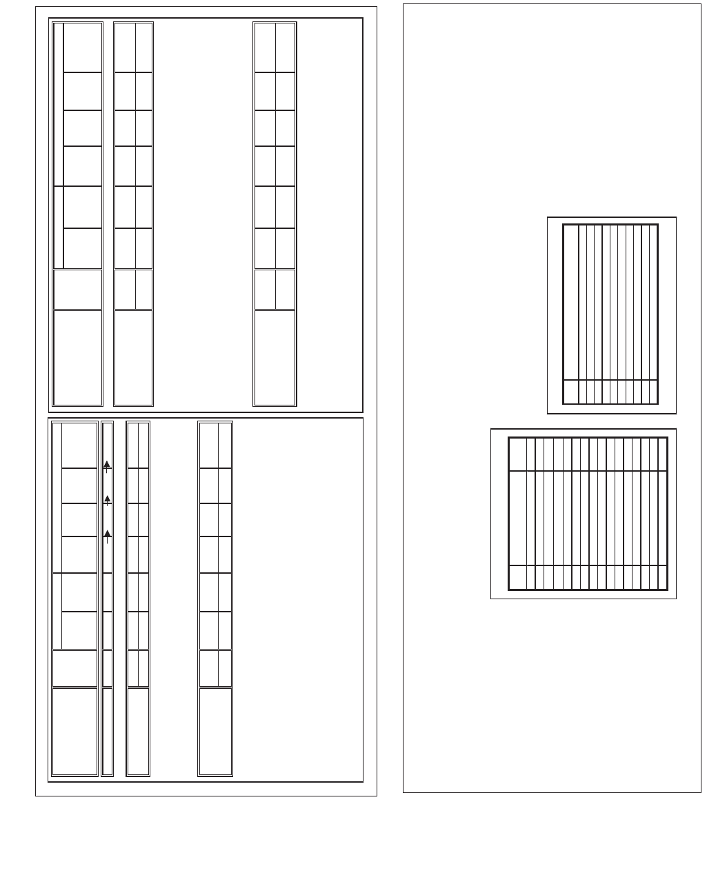
—58—
APPENDIX A — ECONOMI$ER+ LABEL
Button
1
Button
2
DS1
(Red)
DS2
(Yellow)
DS3
(Green)
DS4
(Green)
Action flash flash flash flash
Note 1 Indicators flash in sequence at .5 sec intervals
Names HB ECONO Y1 Y2
Actions flash flash steady steady
Note 1 Heartbeat Indicator flashes to indicate proper operation of the control
Note 2 Econo indicator flashes to indicate free cooling being used
Note 3 Y1 and Y2 are on steady when a call thermostat Y1 and Y2 are closed
Note 4 ERROR - HB and Econo are on steady to indicate the presence of an error
Names READ ADV SET NO I/O NO TEN'S
OR ON
ONES OR
OFF
Actions Push Push flash, no flash no flash no flash no
Note 1 Push and release the READ button to enter Read Mode. The SET NO Indicator flashes once
to indicate the setup point is selected for viewing
Note 2 Push and release ADV button repeatedly to advance to the desired setup point or I/O point
Each time the ADV button is pushed, the SET NO flashes the point number until the desired
I/O point is reached and then the I/O NO flashes the I/O point no.
Note 3 After the SET NO indicator identifies the desired point no, push and release the READ
button to display the value in the TEN's and ONE's indicator (i.e., 5 flashes for a value of 5)
or a steady TEN's indicator for an on and a steady ONE's for off.
To aid in counting, values of 5 are flashed in groups of 5 (i.e., 150 = 3 groups of fast 5 flashes)
and then follow by balance in slow flashes (i.e., 7 = 5 quick flashes + 2 slow flashes)
Note 4 Setpoint values are displayed first followed by I/O values and then back to Setpoint values
Red Set No LED displays Setup item numbers, and Yellow I/O LED displays I/O item no
Note 5 Routine exits after 10 min of no activity or push and hold button 1 and 2 for 3 seconds to exit
MODE OF OPERATION
READ MODE
PUSHBUTTONS LED INDICATORS
STARTUP MODE
RUN MODE
Button
1
Button
2
DS1
(Red)
DS2
(Yellow)
DS3
(Green)
DS4
(Green)
Names ADJUST ADV SET NO SETUP TEN'S
OR ON
ONES OR
OFF
Actions Hold/Push Push flash, no steady flash no flash no
Note 1 Push and hold the ADJUST button until the SETUP indicator turns on.
Note 2 Push and release ADV button repeatedly to advance to the desired setup point.
Each time the ADV button is pushed, the SET NO flashes the point number and then displays
the current setting
Note 3 Once the current value has been displayed the TENS indicator will turn on steady and while it
on use the ADJUST button to enter the value. (i.e., push the button 4 times to enter 4)
Then wait for the ONES indicator to turn on and enter the ONES setting
Wait for indicator to turn off and then push read/adjust to check the setting
Note 4 Routine exits after 10 min of no activity or push and hold button 1 and 2 for 3 seconds to exit
Names ADJUST MAN MAN I/O NO TEN'S
OR ON
ONES OR
OFF
Actions Push Hold/Push steady flash no flash no flash no
Note 1 Push and hold the MAN button until the MAN indicator turns on.
Note 2 Push and release MAN button repeatedly to advance to the desired I/O point.
Each time the MAN button is pushed, the I/O NO flashes the I/O point number.
Note 3 After the desired I/O No is reached push and release the ADJUST to toggle the output on
and off or open and closed
Note 4 Routine exits after 10 min of no activity or push and hold button 1 and 2 for 3 seconds to exit
PUSHBUTTONS LED INDICATORS
SETUP MODE
MANUAL
MODE OF OPERATION
I/O POINTS
NO I/O Points UNITS
1 C1 Output -
2 C2 Output -
3 C3 Output -
4 C4 Output -
5 Economizer Damper Output %
6 Supply Air temperature F
7 Outside Air temperature F
8 Return Air Temperature F
9 Indoor Relative Humidity %
10 Outdoor Relative Humidity %
11 Indoor Air Quality PPM
12 Remote Minimum Position %
13 Y1 Status (next version) -
14 Y2 Status (next version) -
15 G Status (next version) -
16 Occ Status (next version) -
ALARM CODES
NO DESCRIPTION
1 SAT sensor invalid
2 RAT Sensor Invalid (only with changeover type 3&5)
3 OAT Sensor Invalid
4 ORH Sensor invalid (only with changeover type 3&4)
5 IRH Sensor invalid (only with changeover type 5)
6 IAQ Sensor Invalid (only if IAQ=1)
7 Y2onY1off
8 Micro Fails E2 test
note 1 Micro Fails RAM test
note 2 Micro Fails ROM test
Note 1 DS1+DS3/DS2+D4 will alternately flash
Note 2 DS1+DS2/DS3+D4 will alternately flash
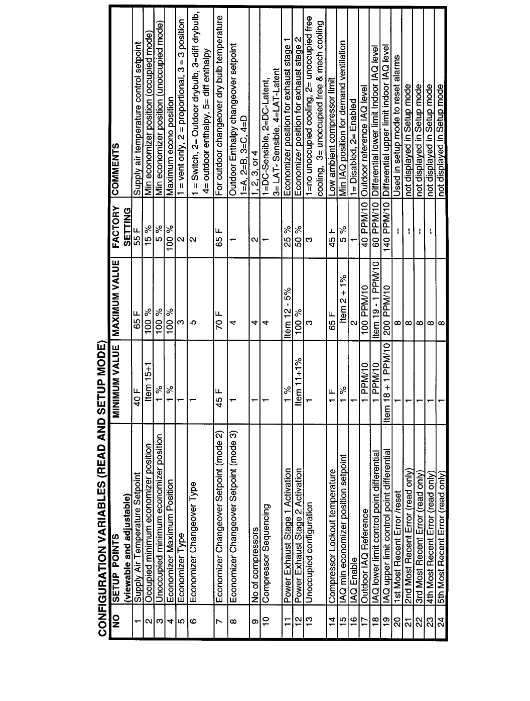
—59—
APPENDIX A — ECONOMI$ER+ LABEL (cont)
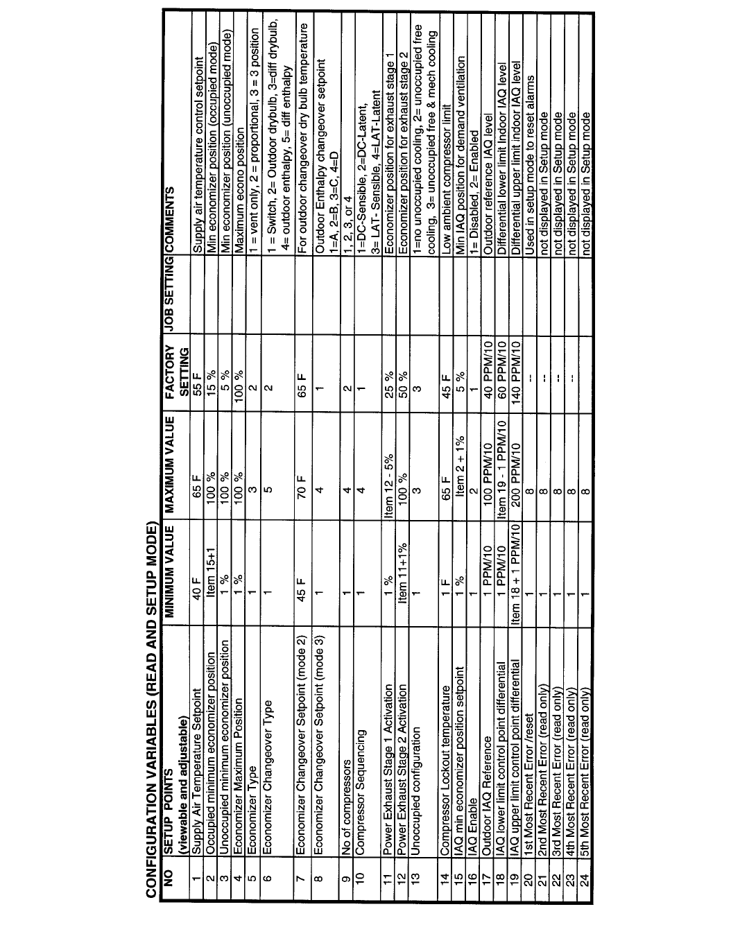
—60—
APPENDIX B — JOB SPECIFIC ECONOMI$ER+ CONFIGURATION SETTINGS
Enter the job specific settings in the “Job Setting” column below.
—61—
INDEX
Access panels 15
Altitude compensation 38
Barometric flow capacity 17
Burner ignition 49
Burner rack 52
Burner section 52
Burner spark gap 52
Charging chart, refrigerant 50, 51
Clearance 2, 3
CO2sensor
Configuration 23
Settings 23
Combustion blower wheel 49
Compressor
Lubrication 48
Mounting 37
Rotation 37
Condensate drain
Cleaning 47
Location 4, 6
Condenser coil 8
Cleaning 47
Condenser fan 8
Adjustment 48
Control circuit
Wiring 10
Wiring raceway 11
Demand control ventilation 22
Dimensions 2, 3, 5
Ductwork 4
EconoMi$er+ 15-23, 39-47
Adjustment 48
Components 15
Configuration 43-45
Controller wiring 17
Damper movement 17
Inputs and Outputs 40
Troubleshooting 53, 54
Wiring 16, 17
Electrical connections 10
Electrical data 12, 13
Enthalpy changeover set points 21
Evaporator coil 8
Cleaning 47
Evaporator fan motor
Lubrication 48
Motor data 25
Mounting 24
Performance 25-36
Pulley adjustment 24
Pulley setting 8
Speed 8, 25
Factory-installed options 14-23
EconoMi$er+ 15-23
Manual outdoor air damper 14
Filter
Cleaning 47
Installation 16
Size 9
Flue gas passageways 48
Flue hood 6, 10
Freeze protection thermostat 9, 49
Gas connection 9
Gas input 9
Gas piping 6, 10, 37
Gas pressure 1, 6, 9
Heat anticipator settings 9, 10
Heat exchanger 9
High flow valves 37
High pressure switch 9, 49
Horizontal units 1, 4
Indoor air humidity sensor 22
Indoor air quality sensor 18
Integrated gas controller 49
Error codes 49, 55
Leak test 37
Limit switch 49
Liquid propane 9
Low pressure switch 9, 49
Main burners 38, 49
Manual outdoor air damper 14
Mounting
Compressor 37
Unit 4
Natural gas 9
Operating limits 4
Operating sequence 45-47
Cooling 45, 46
EconoMi$er+ 46, 47
Heating 46, 47
Outdoor air hood 14, 16
Outdoor air inlet screens
Cleaning 47
Dimensions 9
Outdoor air humidity sensor 19
Outdoor air temperature sensor 18
Physical data 8, 9
Power supply 10
Wiring 11
Pressure switches
High pressure 9, 49
Low pressure 9, 49
Pre-Start-Up 37
Refrigerant
Charge 8, 48
Type 8
Refrigerant service ports 37
Replacement parts 49
Return air filter 9, 37
Return air temperature sensor 18, 19
Rigging unit 4, 7
Roof curb
Assembly 1
Dimensions 5
Connector package 5
Leveling tolerances 6
Weight 8
Safety considerations 1
Safety relief 39
Service 47-52
Service ports 37
Slab mount 4
Start-up 37-47
Start-up checklist CL-1
Thermostat 8
Troubleshooting 53-57
Ventilation 39
Weight
Corner 2, 3
EconoMi$er+ 2, 3, 8
Maximum 6
Unit 2, 3, 7, 8
Wiring
EconoMi$er+ 16
Power connections 11
Thermostat 11
Unit 57

Copyright 2004 Bryant Heating &Cooling Systems CATALOG NO. 5358-023
SERVICE TRAINING
Packaged Service Training programs are an excellent way to increase your knowledge of the
equipment discussed in this manual, including:
• Unit Familiarization • Maintenance
• Installation Overview • Operating Sequence
A large selection of product, theory, and skills programs are available, using popular video-based
formats and materials. All include video and/or slides, plus companion book.
Classroom Service Training which includes “hands-on” experience with the products in our labs
can mean increased confidence that really pays dividends in faster troubleshooting and fewer call-
backs. Course descriptions and schedules are in our catalog.
CALL FOR FREE CATALOG 1-800-644-5544
[ ] Packaged Service Training [ ] Classroom Service Training

Copyright 2004 Bryant Heating &Cooling Systems CL-1 CATALOG NO. 5358-023
CUT ALONG DOTTED LINE CUT ALONG DOTTED LINE
START-UP CHECKLIST
(Remove and Use in Job File)
I. PRELIMINARY INFORMATION:
MODEL NO.: _______________________________________ SERIAL NO.:______________________________________________
DATE: _____________________________________________ TECHNICIAN: ____________________________________________
BUILDING LOCATION: ___________________________________
II. PRE-START-UP (insert checkmark in box as eachitemis completed)
VERIFY THAT ALL PACKING MATERIALS HAVE BEEN REMOVED FROM UNIT
VERIFY THAT CONDENSATE CONNECTION IS INSTALLED PER INSTALLATION INSTRUCTIONS
VERIFY THAT FLUE HOOD IS INSTALLED
CHECK ALL ELECTRICAL CONNECTIONS AND TERMINALS FOR TIGHTNESS
CHECK TO ENSURE NO WIRES ARE TOUCHING REFRIGERANT TUBING OR SHARP EDGES
CHECK GAS PIPING FOR LEAKS
CHECK THAT RETURN-AIR FILTER IS CLEAN AND IN PLACE
VERIFY THAT UNIT INSTALLATION IS LEVEL
CHECK FAN WHEEL AND PROPELLER FOR LOCATION IN HOUSING/ORIFICE AND SETSCREW TIGHTNESS
VERIFY PULLEY ALIGNMENT AND BELT TENSION ARE CORRECT
III. START-UP:
ELECTRICAL
SUPPLY VOLTAGE L1-L2 ____________ L2-L3 ____________ L3-L1 ____________
COMPRESSOR AMPS L1 ____________ L2 ____________ L3 ____________
INDOOR-FAN AMP L1 ____________ L2 ____________ L3 ____________
TEMPERATURES
OUTDOOR-AIR TEMPERATURE _____________ DB _____________ WB ____________
RETURN-AIR TEMPERATURE _____________ DB _____________ WB ____________
COOLING SUPPLY AIR _____________ DB _____________ WB ____________
GAS HEAT SUPPLY AIR _____________ DB
PRESSURES
GAS INLET PRESSURE ____________ IN. WG
GAS MANIFOLD PRESSURE ____________ IN. WG (LOW FIRE) ____________ IN. WG (HI FIRE)
REFRIGERANT SUCTION ____________ PSIG ____________ TEMP ° F
REFRIGERANT DISCHARGE ____________ PSIG ____________ TEMP ° F
VERIFY REFRIGERANT CHARGE USING CHARGING TABLES
VERIFY THAT 3-PHASE SCROLL COMPRESSOR IS ROTATING IN CORRECT DIRECTION
(580F072 AND 073 ONLY)
