Bryant Durapack 558F Users Manual
558D to the manual d4a161fe-fe22-43c5-b3ae-6830c1068b6d
2015-02-02
: Bryant Bryant-Durapack-558F-Users-Manual-411855 bryant-durapack-558f-users-manual-411855 bryant pdf
Open the PDF directly: View PDF ![]() .
.
Page Count: 68
DESCRIPTION
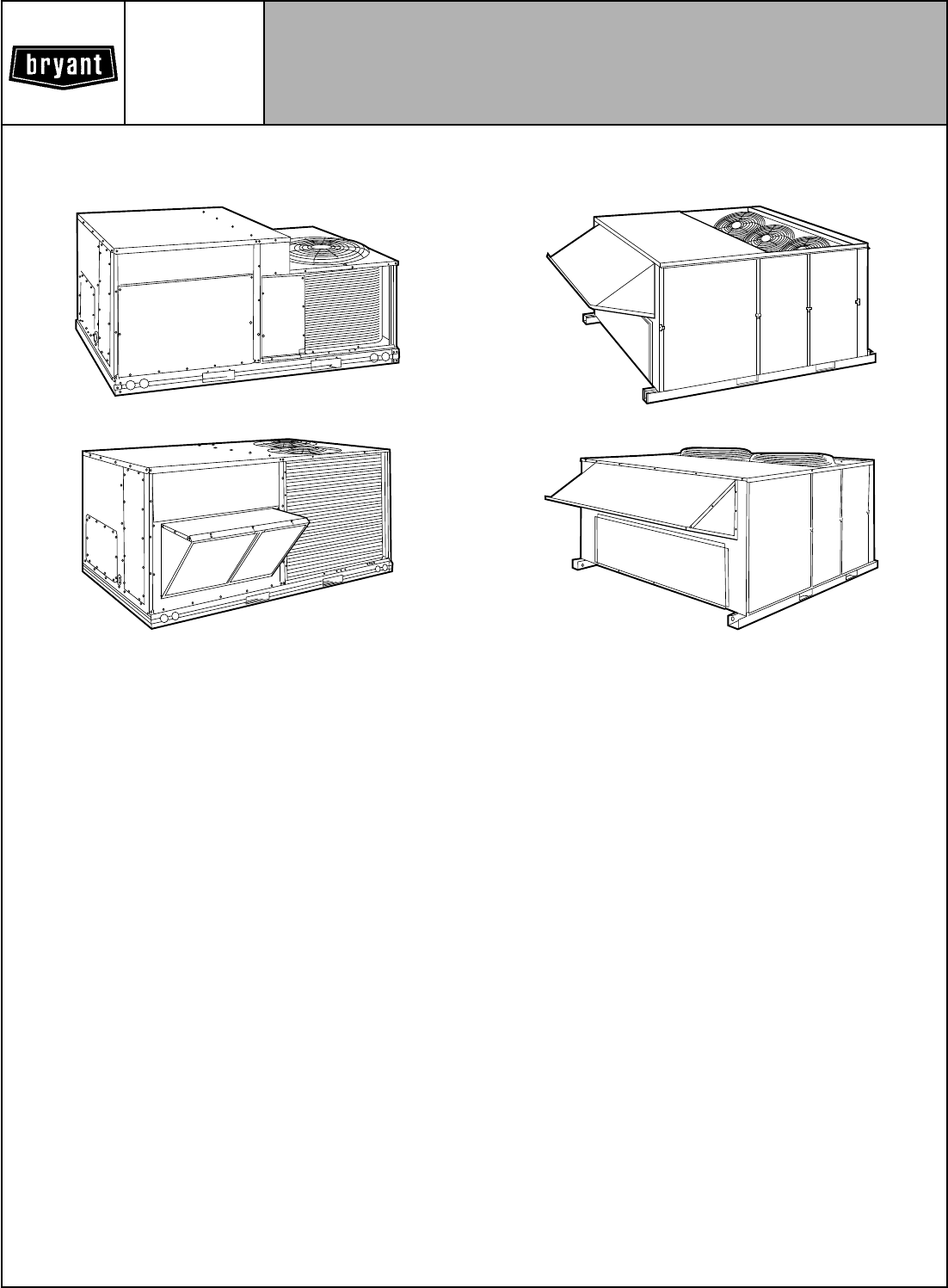
The 558D/559F electric cooling rooftop units are designed to
deliver optimum performance and reliability in a commercial
rooftop unit. The 3 to 25 ton units are one-piece electric cooling
units that are prewired and precharged with R-22 at the factory,
making jobsite installation easy. Every unit is factory run-tested
prior to shipment to ensure reliable installation.
The 558D/559F units are designed to be field-convertible from
vertical supply/return to horizontal supply/return (180-300 units
require an accessory horizontal supply curb or adapter), making
them easily adaptable to a wide variety of new construction and
replacement applications. For vertical supply/return jobs, duct-
work can be connected directly to the roof curb, allowing duct-
work to be completed before unit is available for installation. All
units include easily replaceable internal filters.
The 558D/559F units are available with a range of accessory,
field-installed electric heating sizes and voltage options to meet
most job requirements. Low-voltage terminal blocks make wir-
ing connections quick and simple.
All units are listed with either UL (Underwriters’ Laboratories)
or ETL (ETL Testing Laboratory) and with CSA (Canadian Stand-
ards Association), UL Canada, or ETL Canada. All units are ARI
(Air-Conditioning & Refrigeration Institute) approved (except the
size 300, which is beyond the scope of the ARI Certification pro-
gram) and comply with ASHRAE Standard 62 (American Soci-
ety of Heating, Refrigeration, and Air Conditioning Engineers).
STANDARD FEATURES
EFFICIENT DESIGN means cooling energy savings. Standard
units have EERs (energy efficiency ratios) of up to 9.2, and
SEERs (Seasonal Energy Efficiency Ratios) of up to 10.0 (036-
060 units only).
THE FACTORY-ASSEMBLED PACKAGE (036-150 Units) is a
compact, fully self-contained electric cooling unit that is pre-
wired, prepiped, and precharged for minimum installation
expense.
UNITS MAY BE CONVERTED TO HORIZONTAL DIS-
CHARGE in the field. The units can be modified at the jobsite to
fit a variety of applications (180-300 units require an accessory
horizontal supply/return roof curb or a horizontal supply/return
adapter).
NEW TOOL-LESS FILTER ACCESS PANEL (036-150 Units)
provides easy access to filters. The new panel provides addi-
tional access space, permitting easy filter replacement in the
unit, even with an outdoor-air device mounted in a horizontal
position.
INTERNAL RETURN-AIR FILTERS are provided. Two-in.
throwaway filters are provided standard on all units, and can be
easily accessed through the tool-less access filter door. There is
no need to field-fabricate filter racks or install external filter
accessories.
COMPRESSOR PROTECTION is assured. The 036-150 units
have an internal pressure relief valve and line break (current
overload) protections, and the 180-300 units have high- and
low-pressure and freeze protection external to the compressor.
These protections prohibit operation under abnormal unit
conditions.
Model 558D036-072
Model 558D090-150
Model 559F180,216
Model 559F240,300
Bryant
Air Conditioning COMMERCIAL
SINGLE-PACKAGE ROOFTOP
ELECTRIC COOLING UNITS
Model 558D/559F
Sizes 036-300
3to25Tons
Form No. PDS 558D.36.5B
DUAL COMPRESSORS AND DUAL REFRIGERATION CIR-
CUITS (090-150 and 216-300 Units) are provided. Two com-
pressors, each on its own independent circuit, provide standby
reliability and high operating efficiency.
ADVANCED DESIGN of evaporator and condenser coils pro-
vides optimum heat transfer and cooling efficiency. Coils are
computer-designed with advanced heat transfer surfaces, and
are fabricated of copper tubing with aluminum fins.
COMMERCIAL STRENGTH BASE RAILS (full-perimeter on
036-150 units) with built-in rigging capability allow easy rigging
of unit.
WEATHER-RESISTANT CABINET is built for durability in any
climate. The cabinet is made of pre-painted, galvanized steel for
long life and high-quality appearance.
LOW-AMBIENT OPERATION is provided standard on most
units. The 036-150 units and the 240 units operate in cooling
down to 25 F as shipped from the factory. The 180 units operate
down to 40 F, the 216 units operate down to 35 F, and the
300 units operate down to 48 F. Low-ambient kits are not re-
quired for most applications.
HERMETICALLY-SEALED COMPRESSORS on the 036-150
units prevent contamination to help promote longer life and de-
pendable operation. The 180-300 units have semi-hermetic
compressors.
COMPRESSOR VIBRATION ISOLATION MOUNTING on all
units eliminates noise-causing vibration transmission into the
conditioned space.
CRANKCASE HEATERS on the 180-300 units keep the oil free
of refrigerant during the off cycle for added compressor life and
reliability. Crankcase heaters are not necessary on the 036-150
units due to high-side crankcase design (072,150 units) and low
refrigerant charge levels (036-150 units).
POWER AND CONTROL CONNECTIONS are made on the
same side of the unit to simplify installation.
STANDARD WARRANTIES include 1 year on parts, with an ad-
ditional 4 years on compressors (036-180 units). Additional ex-
tended warranties are also available.
3 TO 6 TON UNITS WEIGH LESS THAN 500 LB as standard
from the factory. This can eliminate the need for structural en-
gineering approval on replacement jobs.
BELT-DRIVEN EVAPORATOR-FAN MOTORS are standard on
all 6 to 25 ton units, allowing adjustment of the available static
pressure to meet the job requirements of even the most de-
manding applications. Belt-driven evaporator-fan motors are
available as a factory-installed option on the 3 to 5 ton units.
FACTORY-INSTALLED OPTIONS
DESCRIPTION AND USAGE
Durablade (036-150) and Standard Integrated (180-300)
Economizers — The economizer will allow a fixed percentage
(between 0 and 100%) outdoor ventilation air into the unit any
time the evaporator fan is running. A dry-bulb thermostat placed
outdoors will bring in up to 100% outdoor air whenever the tem-
perature of the outdoor air alone will adequately provide cooling.
If the economizer alone cannot provide enough cooling, then si-
multaneous economizer and compressor operation will provide
the most economical operation.
SUGGESTED USE:
• To allow a fixed percentage of outdoor air any time the evapo-
rator fan is on, or operates in economizer mode if outdoor air
can provide cooling, but closes when the evaporator fan is off
to prevent cold backdrafts and wasted energy.
• To reduce energy usage. Use whenever the number of hours
of operation at below 55 F is significant.
• The damper may be used on either vertical or horizontal
applications.
Parablade Economizer (036-150 Units) — The unique design
of the Parablade economizer saves energy while providing eco-
nomical and reliable cooling. The new design uses a parallel-
opposed blade damper to permit outdoor ventilation air to enter
the unit any time the evaporator fan is running. The economizer
will permit cooling using 100% outdoor air whenever outdoor air
alone will provide adequate cooling. If the economizer alone
cannot provide enough cooling, then simultaneous economizer
and compressor operations will provide the most economical
operation. The economizer also has built-in spring return for re-
liable close-on-power loss. The Parablade design incorporates
standard enthalpy controls.
SUGGESTED USE:
• To allow a fixed percentage of outdoor air on vertical applica-
tions any time the evaporator fan is on, or to operate in econo-
mizer mode if outdoor air can provide cooling, but closes
when the evaporator fan is off to prevent cold backdrafts and
wasted energy.
• To reduce energy usage. Use whenever the number of hours
of operation at below 55 F is significant.
NOTE: Indoor-air quality (IAQ) restrictions require enthalpy con-
trols to help regulate humidity in the occupied space.
25% and 50% Manual Outdoor-Air Damper — Package con-
sists of a damper which can be set at 25% or 50% (036-150)
outdoor air. The package includes a rainhood and birdscreen.
SUGGESTED USE:
• To allow a fixed percentage of outdoor air for ventilation under
all conditions.
• The damper may be used on either vertical or horizontal
applications.
NOTE: The 25% manual outdoor-air damper will be factory
installed whenever the factory-installed economizer is not
chosen on the 180-300 units.
Alternate Evaporator-Fan Motors (036-060,120,150 Units)
and Drives (036-060,090,120,150 Units) — Alternate motors
and/or drives allow operation of the evaporator fan at conditions
outside the range of the standard factory motor and drive
combination.
SUGGESTED USE:
• When higher static/airflow is required to meet job conditions.
CONTENTS
Page
Model Description ............................4
ARI Capacity Ratings .........................5
Dimensional Drawings .......................6-13
Specifications ............................14-16
Selection Procedure .........................17
Gross Cooling Capacities ....................18-25
Air Delivery ..............................26-46
Electrical Data............................49-54
Operating Sequence .........................55
Typical Wiring Schematic .....................56,57
Typical Installation .........................58,59
Application Data ..........................60-63
Electric Heater Capacities .....................64
Engineers’ Specification Guide .................65,66
2
Controls Upgrade Kit (036-150 Units) — The controls kit in-
cludes high-pressure, loss-of-charge/low-pressure, and freeze
protection cutout switches. The high-pressure and loss-of-
charge/low-pressure switches can be easily added by screwing
the switches onto Schrader-type fittings provided on the refrig-
erant lines.
SUGGESTED USE:
• Kit provides additional protection against system high pres-
sure, loss-of-charge/low pressure, and evaporator coil frost
build-up for 036-150 units.
NOTE: These switches are standard on the 180-300 units.
Condenser Coil Grille (036-150 units) — The grille protects
the condenser coil from damage and requires no additional
clearance.
SUGGESTED USE:
• When unit is located in high traffic areas or could be subject to
damage.
• As an alternate location for the field-supplied disconnect
switch.
FIELD-INSTALLED ACCESSORY
DESCRIPTION AND USAGE
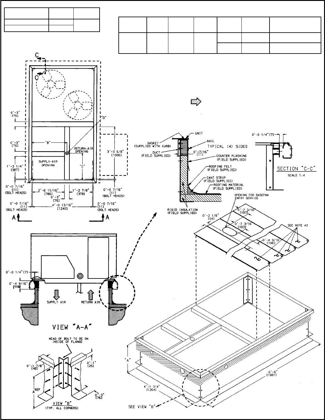
Roof Curbs (Vertical and Horizontal) — Full-perimeter galva-
nized steel support frame in 14- and 24-in. high designs pro-
vides wood nailer to attach roof counter flashing. Insulated
basepans in curb are provided to prevent condensation. Duct-
work attaches to rails provided in the roof curb. A gasket is pro-
vided to form an air- and watertight seal between unit and curb.
The gasket meets the standards of the NRCA (National Roofing
Contractors’ Association).
SUGGESTED USE:
• Rooftop application for vertical discharge.
• Slab-mounted applications when elevation of the unit is
necessary.
Horizontal Adapter (180-300 Units) — The curb is prefabri-
cated, easily field-assembled, and permits full perimeter mount-
ing. The curb also improves unit static performance by up to
0.6 in. wg.
SUGGESTED USE:
• Rooftop application for horizontal discharge on 180-300 units.
• Rooftop applications for horizontal discharge on 180-300
units where high air delivery cfms are required.
Condenser Coil Hail Guard (036-150 Units) — Package con-
sists of a hood and coil grille which attach to the condenser coil.
SUGGESTED USE:
• To protect the condenser coil from hail and other debris on
036-150 units.
• As an alternate location for field-installed disconnect switch.
Condenser Coil Grille (036-150 Units) — The grille protects
the condenser coil from damage and requires no additional
clearance.
SUGGESTED USE:
• When unit is located in high traffic areas or could be subject to
damage.
• As an alternate location for the field-supplied disconnect
switch.
25% and 50% Manual Outdoor-Air Dampers (036-150 Units)
—Package consists of a damper which can be set at either
25% or 50% outdoor air (as appropriate). The package includes
a rainhood, birdscreen, and a panel with a hole in it for easy
installation.
SUGGESTED USE:
• To allow a fixed percentage of outdoor air for ventilation under
all conditions.
• The damper may be used on either vertical or horizontal
applications.
Two-Position Dampers — Package consists of a low-leak
damper assembly and a panel with a hole in it for easy instal-
lation (036-150 units). The damper will allow either 0 or 25% or
100% (depending on accessory package) outdoor air into the
unit any time the evaporator fan is running, and features close-
on-power-loss. When the evaporator fan is off, the damper will
be closed.
SUGGESTED USE:
• Allows a fixed percentage of outdoor air any time the evapo-
rator fan is on, but closes when the evaporator fan is off to
prevent cold backdrafts and wasted energy.
• The damper may be used on either vertical or horizontal air-
flow applications.
Economizers — See descriptions listed under Factory-
Installed Options Description and Usage section on page 2.
NOTE: When the accessory Durablade economizer is ordered
for the 036-150 units, the package also contains an outdoor-air
panel for easy installation.
Solid-State Enthalpy Control (036-150 Units) — Package
consists of a solid-state control and sensor which is capable of
sensing outdoor-air heat content (temperature and humidity)
and controlling economizer cut-in point to have minimum heat
content air passing over the evaporator coil. The solid-state en-
thalpy control replaces the standard dry-bulb thermostat in the
economizer.
SUGGESTED USE:
• To enhance economizer operation for additional energy
savings.
Enthalpy Control Sensor — Package consists of a solid-state
sensor to be used in conjunction with the solid-state enthalpy
control (036-150 units) or paired with a second enthalpy sensor
(180-300 units) for differential enthalpy control. This sensor is
mounted on the economizer assembly so that it can sense
building temperature. The 2 sensors will determine which com-
bination of outdoor and return air will provide the greatest en-
ergy savings.
SUGGESTED USE:
• To enhance economizer operation for maximum energy
savings.
NOTE: On 180-300 units, a single sensor may be used for
single-sensor, outdoor-air enthalpy control if desired.
Time GuardTII Device — Package consists of a control to be
field wired into the unit controls, and provides a 5-minute delay
in compressor operation between cooling cycles.
SUGGESTED USE:
• Prevents compressor short cycling when rapid compressor
cycles may be a problem.
Controls Upgrade Kit (036-150 Units) — See description
listed under Factory-Installed Options Description and Usage
section on page 2.
Fan/Filter Status (036-150 Units) — Provides status of indoor
(evaporator) fan (ON/OFF) or filter (CLEAN/DIRTY). Status
shall be displayed with a field-supplied indicator light at the
thermostat.
SUGGESTED USE:
• To assist in servicing the unit.
3
Head Pressure Control — Kit consists of an outdoor-air ther-
mostat that permits adequate head pressure control during
cooling operation at low outdoor-ambient temperatures.
Refer to Trade Prices for more details or contact your local
representative.
SUGGESTED USE:
• When cooling at low-ambient outdoor temperatures is
desired.
NOTE: The head pressure control is not necessary for 036-150
units to allow cooling operation down to 25 F.
Low-Ambient Kit — Kit consists of a solid-state control and
condenser coil temperature sensor to cycle the condenser-fan
motors in order to maintain condenser-coil head pressure for
proper cooling operation. Refer to Trade Prices for more
details or contact your local representative.
SUGGESTED USE:
• Whenever cooling is required at low outdoor ambient tem-
peratures (as low as −20 F).
• Low-ambient kit is not usually required when economizer is
used.
Electric Heat Packages — Each package consists of one or
more heater modules. Each module slides into keyed mounting
slots in the fan discharge section.
SUGGESTED USE:
• To provide heat in the unit when required.
Single Point Packages (036-150 Units) — Each package con-
sists of a control box, which provides a watertight and UL and
UL Canada approved connection point for electric heat kits.
SUGGESTED USE:
• Required with all electric heat packages for UL and UL
Canada approved single point electrical connection on 036-
150 units.
Thermostats and Subbases — Provide staged cooling and
heating, automatic (or manual) changeover, fan control, and in-
dicator light.
SUGGESTED USE:
• To control unit operations.
Barometric Relief Package (180-300 Units) — This package
is useful when it is necessary to remove excess pressure from
the conditioned space.
NOTE: Optional economizer is required with this accessory.
SUGGESTED USE:
• When the job requires the ability to relieve internal building
pressure using 180-300 units.
Power Exhaust (180-300 Units) — This package is useful
when it is necessary to remove excess pressure from the con-
ditioned space.
NOTE: Optional economizer is required with this accessory.
SUGGESTED USE:
• When the job requires the ability to relieve internal building
pressure and pressure losses through the return-air ductwork
are greater than 0.20 in. wg using 180-300 units.
• When the job requires the ability to move large quantities
of air to relieve pressure in the conditioned space using
180-300 units.
Winter Start Time Delay Relay (216-300 Units) — Used in
conjunction with accessory low-ambient kit or head pressure
control device, permits operation in cooling at lower outdoor am-
bient temperatures. See Trade Prices for more details or contact
your local representative.
SUGGESTED USE:
• When job requires the ability to operate in cooling at low
outdoor-ambient temperatures.
Thru-The-Bottom Power Connection (036-150 Units) —
Used to make power connections through the bottom of the unit.
SUGGESTED USE:
• When utility connections need to be made through the bottom
of the unit.
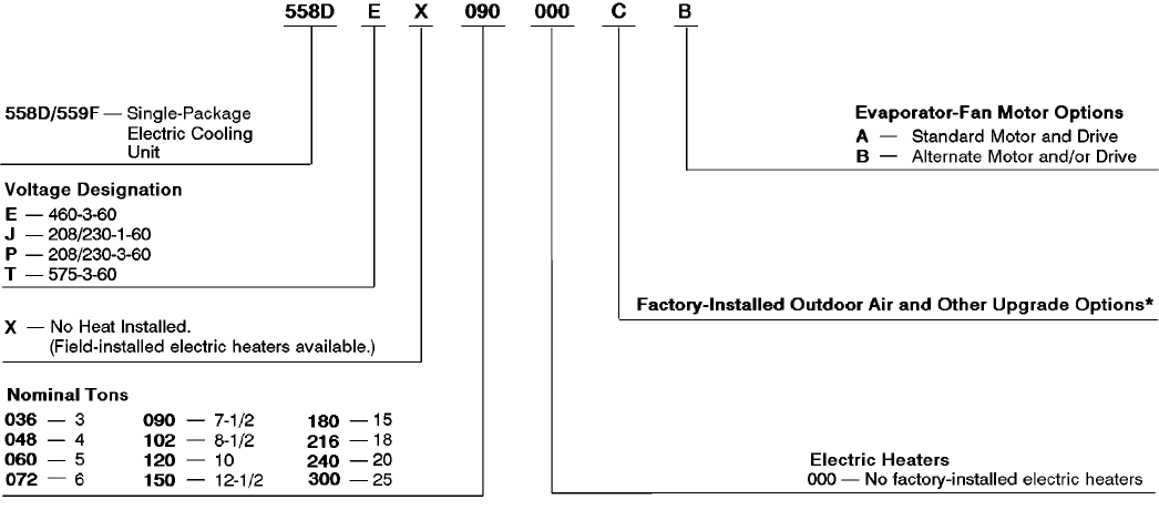
MODEL DESCRIPTION
(ODS Model Number)
LEGEND
ODS — Order Distribution System
*Refer to Trade Price Sheets or contact your local representative for specific information regarding which options are available on which units.
4
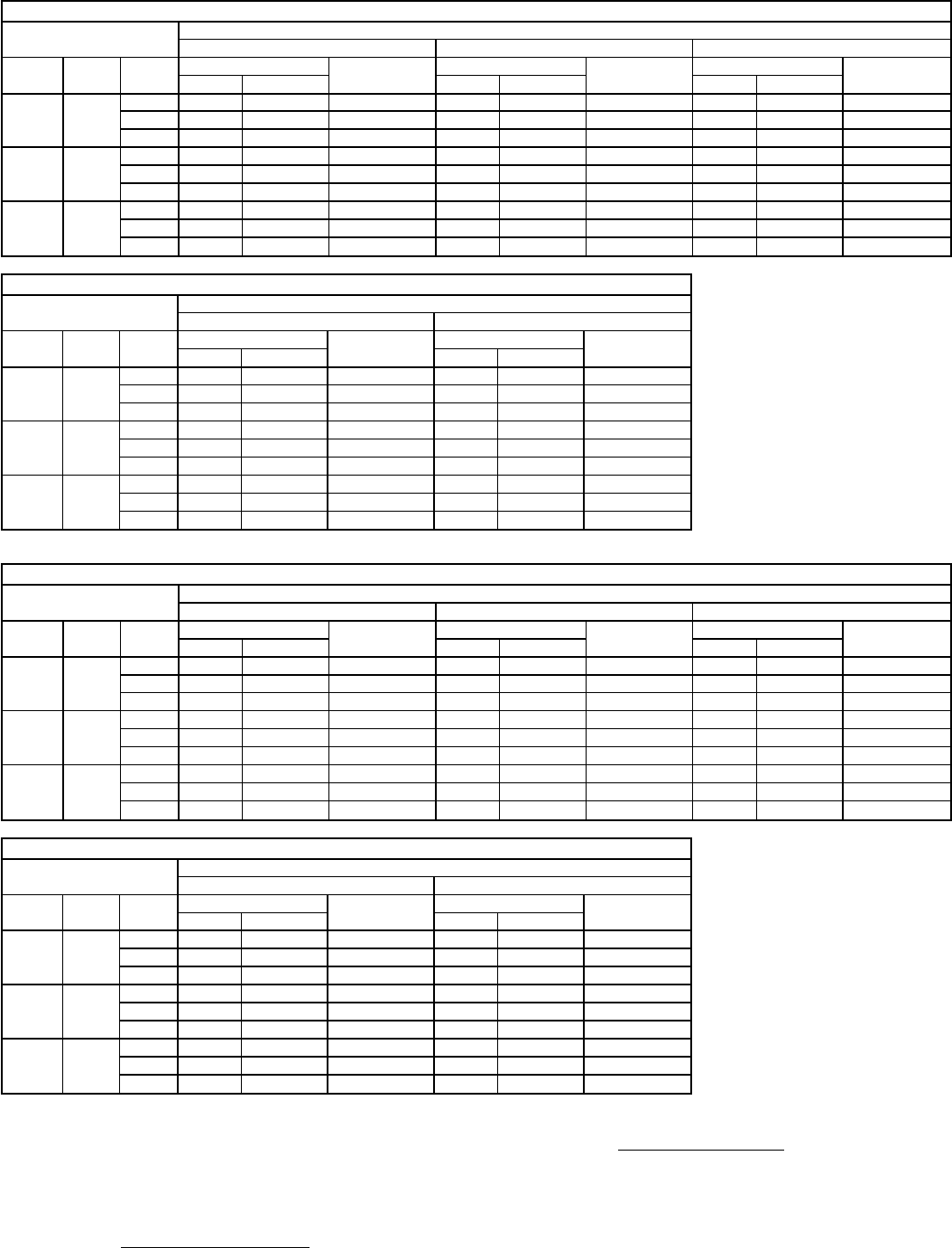
ARI* CAPACITY RATINGS
UNIT 558D NOMINAL
TONS STANDARD
CFM NET COOLING
CAPACITY (Btuh) TOTAL
kW
SEER† EER SOUND
RATING
(Bels)
Belt Drive Direct Drive
036 3 1200 35,000 4.0 10.0 9.7 8.7 8.2
048 4 1600 47,000 5.5 10.0 9.7 8.6 8.2
060 5 2000 57,500 6.7 10.0 9.7 8.5 8.2
UNIT NOMINAL
TONS STANDARD
CFM NET COOLING
CAPACITY (Btuh) TOTAL
kW EER IPLV SOUND
RATING
(Bels)
558D072 6 2100 70,000 7.9 8.9 ** 8.4
558D090 7
1
⁄
2
2800 86,000 9.6 8.9 9.35 8.6
558D102 8
1
⁄
2
3000 98,000 11.0 9.0 9.00 8.6
558D120 10 4000 117,000 13.0 9.0 9.35 8.8
558D150 12
1
⁄
2
4500 142,000 15.8 9.2 9.65 8.8
559F180 15 5250 178,000 20.7 8.6 10.70 8.8
559F216 18 6000 190,000 21.3 8.9 9.20 9.0
559F240 20 6200 222,000 25.5 8.7 8.80 9.5
559F300 25 7200 268,000 31.2 8.6 8.40 9.5
LEGEND
Bels — Sound Levels (1 bel = 10 decibels)
EER — Energy Efficiency Ratio
IPLV — Integrated Part-Load Values
SEER — Seasonal Energy Efficiency Ratio
*Air Conditioning and Refrigeration Institute.
†Applies only to units with capacity of 65,000 Btuh or less.
**The IPLV applies only to 2-stage cooling units.
NOTES:
1. Rated in accordance with ARI Standards 210/240-89 (unit sizes 036-120) or 360-86 (unit sizes 150-240) and 270-84.
2. Ratings are net values, reflecting the effects of circulating fan heat. The 300 size is beyond the scope of the ARI certification
program.
3. Ratings are based on:
Cooling Standard: 80 F db, 67 F wb indoor entering-air temperature and 95 F db air entering outdoor unit.
IPLV Standard: 80 F db, 67 F wb indoor entering-air temperature and 80 F db outdoor entering-air temperature.
SIZES 036-150 SIZES 180-300
5
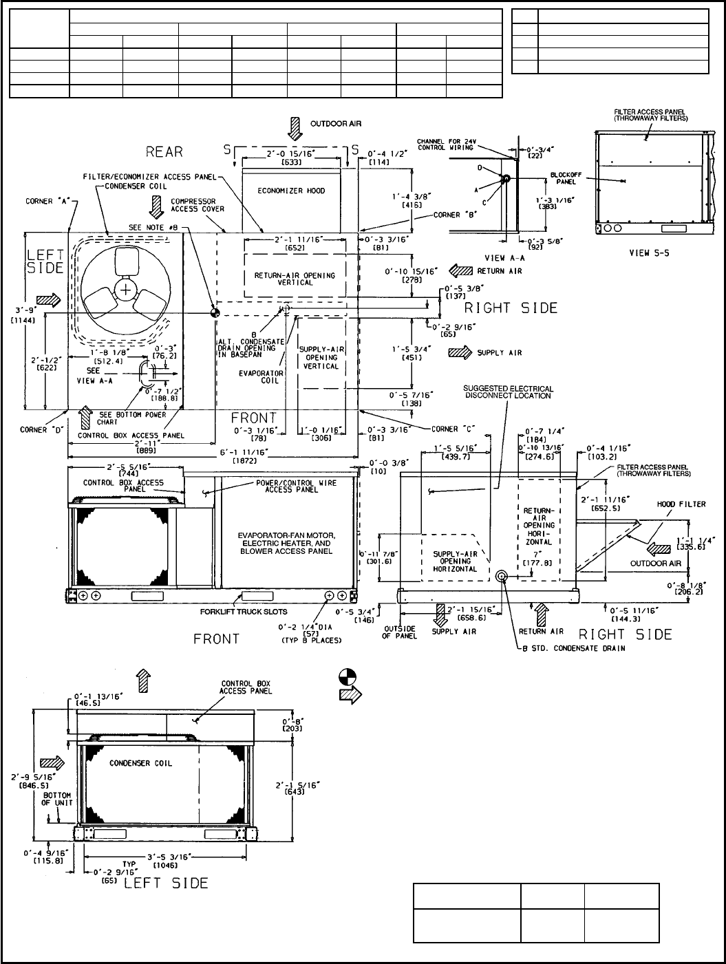
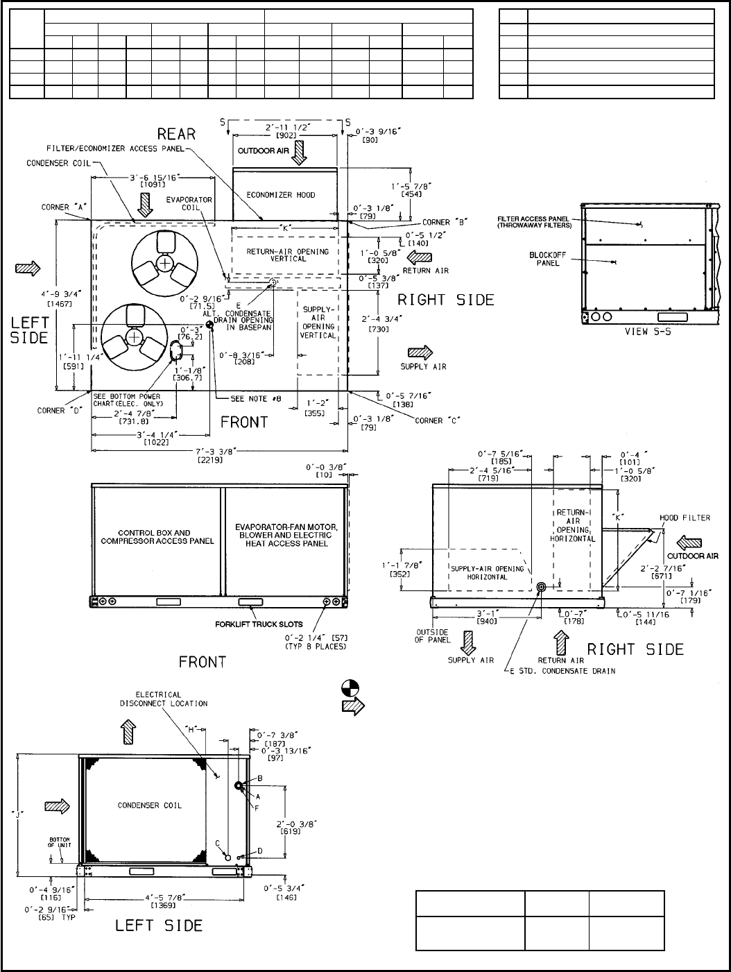
DIMENSIONAL DRAWING — 558D036-072
UNIT
558D
CORNER WEIGHT*
ABCD
Lb Kg Lb Kg Lb Kg Lb Kg
036 126 57.2 89 40.4 111 50.3 39 17.7
048 128 58.1 90 40.8 114 51.7 43 19.5
060 132 59.9 94 42.6 120 54.4 49 22.2
072 148 67.1 103 46.7 155 70.3 64 29.0
*Weights are for unit only (aluminum plate fins) and do not include options or crating.
CONNECTION SIZES
A1
1
⁄
8
9Dia. [28.6] Field Power Supply Hole
B
3
⁄
4
9-14 NPT Condensate Drain
C1
3
⁄
8
9Dia. [35] Power Supply Knockout
D29Dia. [50.8] Power Supply Knockout
NOTES:
1. Dimensions in [ ] are in millimeters.
2. Center of gravity.
3. Direction of airflow.
4. Ductwork to be attached to accessory roof curb only.
5. Minimum clearance (local codes or jurisdiction may prevail):
a. Bottom to combustible surfaces (when not using curb) 0 inches. On horizontal discharge units with
electric heat 1 in. clearance to ductwork for 1 ft.
b. Condenser coil, for proper airflow, 36 in. one side, 12 in. the other. The side getting the greater clear-
ance is optional.
c. Overhead, 60 in. to assure proper condenser fan operation.
d. Between units, control box side, 42 in. per NEC (National Electrical Code).
e. Between unit and ungrounded surfaces, control box side, 36 in. per NEC.
f. Between unit and block or concrete walls and other grounded surfaces, control box side,
42 in. per NEC.
g. Horizontal supply and return end, 0 inches.
6. With the exception of the clearance for the condenser coil or combustible surfaces as stated in
Notes 5a and b, a removable fence or barricade requires no clearance.
7. Units may be installed on combustible floors made from wood or class A, B, or C roof covering material.
8. The vertical center of gravity is 18-6
1
⁄
2
9[470] up from the bottom of the base rail. Horizontal center of
gravity is shown.
BOTTOM POWER CHART, THESE HOLES REQ’D FOR USE
WITH ACCESSORY PACKAGES — CRBTMPWR001A00
(
1
⁄
2
(,
3
⁄
4
() OR CRBTMPWR002A00 (
1
⁄
2
(,1
1
⁄
4
()
THREADED CONDUIT
SIZE WIRE SIZE REQ’D HOLE
SIZES (MAX.)
1
⁄
2
(24 v
7
⁄
8
9[22.2]
3
⁄
4
(POWER† 1
1
⁄
8
9[28.4]
1
1
⁄
4
(POWER† 1
3
⁄
4
9[44.4]
†Select either
3
⁄
4
9or 1
1
⁄
4
9for power, depending on wire size.
6
DIMENSIONAL DRAWING — 558D090-150
UNIT
558D
CORNER WEIGHT* DIMENSIONS
A B C D ‘‘H’’ ‘‘J’’ ‘‘K’’
Lb Kg Lb Kg Lb Kg Lb Kg Ft-in. mm Ft-in. mm Ft-in. mm
090 164 74 140 64 208 94 243 110 1-2
7
⁄
8
378 3-5
5
⁄
16
1050 2-9
11
⁄
16
856
102 165 75 141 64 209 94 245 111 3-3
7
⁄
8
1013 3-5
5
⁄
16
1050 2-9
11
⁄
16
856
120 199 90 170 77 252 114 294 134 2-5
7
⁄
8
759 4-1
5
⁄
16
1253 3-0
3
⁄
8
924
150 202 92 172 78 256 116 300 136 1-2
7
⁄
8
378 4-1
5
⁄
16
1253 3-0
3
⁄
8
924
*Weights are for unit only (aluminum plate fins) and do not include options or crating.
NOTES:
1. Dimensions in [ ] are in millimeters.
2. Center of gravity.
3. Direction of airflow.
4. Ductwork to be attached to accessory roof curb only.
5. Minimum clearance (local codes or jurisdiction may prevail):
a. Bottom to combustible surfaces (when not using curb) 0 inches. On horizontal discharge units with
electric heat 1 in. clearance to ductwork for 1 ft.
b. Condenser coil, for proper airflow, 36 in. one side, 12 in. the other. The side getting the greater clear-
ance is optional.
c. Overhead, 60 in. to assure proper condenser fan operation.
d. Between units, control box side, 42 in. per NEC (National Electrical Code).
e. Between unit and ungrounded surfaces, control box side, 36 in. per NEC.
f. Between unit and block or concrete walls and other grounded surfaces, control box side,
42 in. per NEC.
g. Horizontal supply and return end, 0 inches.
6. With the exception of the clearance for the condenser coil and combustible surfaces as stated in
Notes 5a and b, a removable fence or barricade requires no clearance.
7. Units may be installed on combustible floors made from wood or class A, B, or C roof covering material.
8. The vertical center of gravity is 18-7
1
⁄
2
9[495] for 090 and 102, 28-09[610] for 120 and 150 up from the
bottom of the base rail. Horizontal center of gravity is shown.
BOTTOM POWER CHART, THESE HOLES REQ’D FOR USE
WITH ACCESSORY PACKAGES — CRBTMPWR001A00
(
1
⁄
2
(,
3
⁄
4
() OR CRBTMPWR002A00 (
1
⁄
2
(,1
1
⁄
4
()
THREADED CONDUIT
SIZE WIRE SIZE REQ’D HOLE
SIZES (MAX.)
1
⁄
2
(24 v
7
⁄
8
9[22.2]
3
⁄
4
(POWER† 1
1
⁄
8
9[28.4]
1
1
⁄
4
(POWER† 1
3
⁄
4
9[44.4]
†Select either
3
⁄
4
9or 1
1
⁄
4
9for power, depending on wire size.
CONNECTION SIZES
A1
3
⁄
8
9Diameter [35] Field Power Supply Hole
B2
1
⁄
2
9Diameter [64] Power Supply Knockout
C1
3
⁄
4
9Diameter [44] Charging Port Hole
D
7
⁄
8
9Diameter [22] Field Control Wiring Hole
E
3
⁄
4
9-14 NPT Condensate Drain
F29Diameter [51] Power Supply Knockout
7
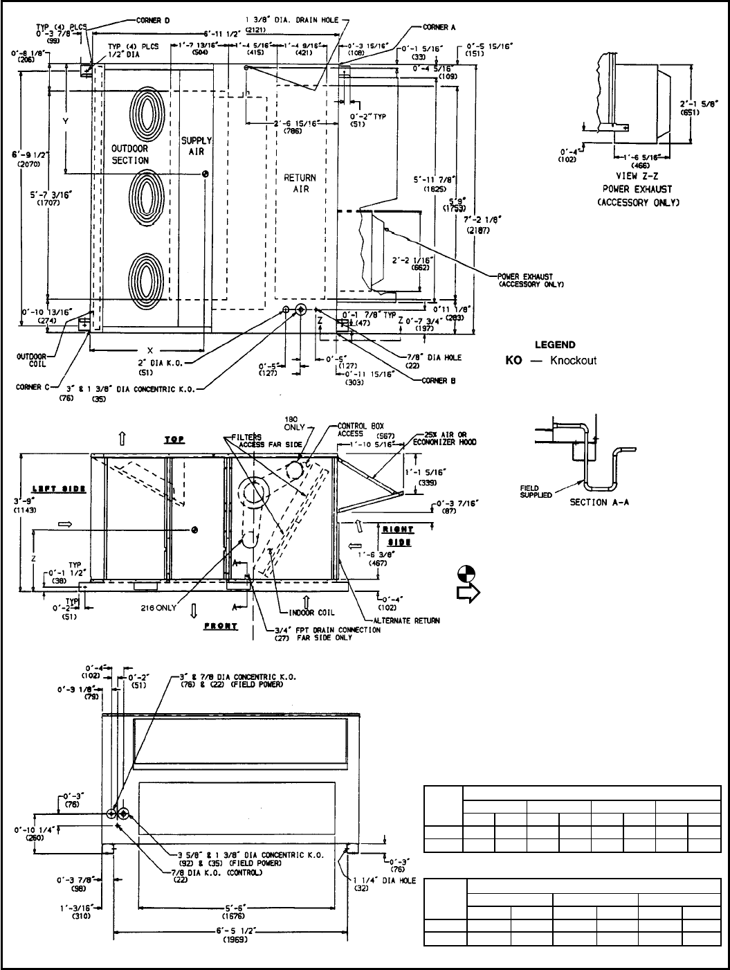
DIMENSIONAL DRAWING — 559F180,216
LEGEND
KO—Knockout
NOTES:
1. Dimensions in ( ) are in millimeters.
2. Center of gravity.
3. Direction of airflow.
4. Ductwork to be attached to accessory roof curb or adapter only.
5. For units with electric heat, a field-supplied 90° elbow must be
installed in the supply ductwork below the unit discharge
connection.
6. Minimum clearance:
a. Rear: 78-09(2134) for coil removal. This dimension can be re-
duced to 48-09(1219) if conditions permit coil removal from the
top.
b. Left side: 48-09(1219) for proper condenser coil airflow.
c. Front: 48-09(1219) for control box access.
d. Right side: 48-09(1219) for proper operation of damper and
power exhaust if so equipped.
e. Top: 68-09(1829) to assure proper condenser fan operation.
f. Local codes or jurisdiction may prevail.
7. With the exception of clearance for the condenser coil and the
damper/power exhaust as stated in note no. 6, removable fence or
barricade requires no clearance.
8. Dimensions are from outside of corner post. Allow 08-
5
⁄
16
9(8) on
each side for top panel drip edge.
UNIT
559F
CORNER WEIGHT*
ABCD
Lb Kg Lb Kg Lb Kg Lb Kg
180 357 162 348 158 333 151 512 232
216 335 152 470 213 598 271 647 293
*Weights are for unit only and do not include options or crating.
UNIT
559F
DIMENSIONS
XYZ
Ft-in. mm Ft-in. mm Ft-in. mm
180 4-10 1219 3-2 965 1-10 559
216 3-10 1168 3-7 1092 1- 8 508
8
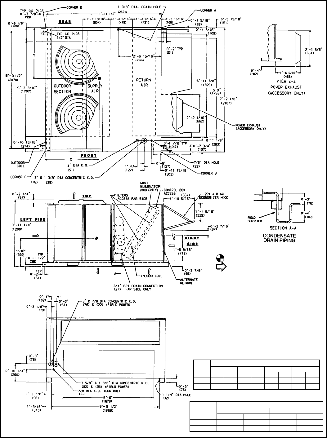
DIMENSIONAL DRAWING — 559F240,300
NOTES:
1. Dimensions in ( ) are in millimeters.
2. Center of gravity.
3. Direction of airflow.
4. Ductwork to be attached to accessory roof curb or adapter
only.
5. For units with electric heat, a field-supplied 90° elbow must
be installed in the supply ductwork below the unit discharge
connection.
6. Minimum clearance:
a. Rear: 78-09(2134) for coil removal. This dimension can
be reduced to 48-09(1219) if conditions permit coil re-
moval from the top.
b. Left side: 48-09(1219) for proper condenser coil airflow.
c. Front: 48-09(1219) for control box access.
d. Right side: 48-09(1219) for proper operation of damper
and power exhaust if so equipped.
e. Top: 68-09(1829) to assure proper condenser fan
operation.
f. Local codes or jurisdiction may prevail.
7. With the exception of clearance for the condenser coil and
the damper/power exhaust as stated in note no. 6, remov-
able fence or barricade requires no clearance.
8. Dimensions are from outside of corner post. Allow 08-
5
⁄
16
9(8)
on each side for top panel drip edge.
UNIT
559F
CORNER WEIGHT*
ABCD
Lb Kg Lb Kg Lb Kg Lb Kg
240 497 225 470 213 461 209 672 305
300 513 233 532 241 542 246 563 255
*Weights are for unit only and do not include options or crating.
UNIT
559F
DIMENSIONS
XY
Ft-in. mm Ft-in. mm
240 3-7 1092 3-2 965
300 3-5 1035 3-7 1092
9
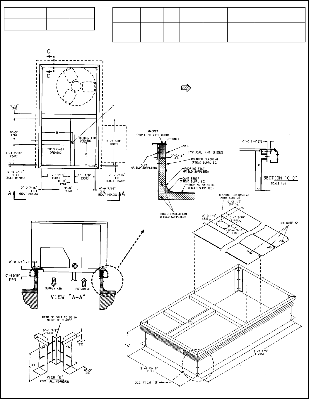
DIMENSIONAL DRAWING — ROOF CURB, 558D036-072
ROOF CURB
ACCESSORY ‘‘A’’ UNIT SIZE
558D
CRRFCURB001A00 18-29[356] 036-072
CRRFCURB002A00 28-09[610]
UNIT SIZE
558D ‘‘B’’ ‘‘C’’ ‘‘D’’ ALT
DRAIN
HOLE POWER CONTROL CONNECTOR
PKG ACY
036-072 18-9
11
⁄
16
9
[551] 18-49
[406] 1
3
⁄
4
9[45]
3
⁄
4
9NPT
1
⁄
2
9NPT CRBTMPWR001A00*
(THRU-THE-BOTTOM)
1
1
⁄
4
9NPT
1
⁄
2
9NPT CRBTMPWR002A00*
(THRU-THE-BOTTOM)
*Either connector package available for either roof curb.
NOTES:
1. Roof curb accessory is shipped unassembled.
2. Insulated panels.
3. Dimensions in [ ] are in millimeters.
4. Roof curb: galvanized steel.
5. Attach ductwork to curb (flanges of duct rest on curb).
6. Service clearance 4 ft on each side.
7. Direction of airflow.
10
DIMENSIONAL DRAWING — ROOF CURB, 558D090-150
ROOF CURB
ACCESSORY ‘‘A’’ UNIT SIZE
558D
CRRFCURB003A00 18-29[356] 090-150
CRRFCURB004A00 28-09[610]
SERVICE PLATE SIZES
UNIT SIZE
558D ‘‘B’’ ‘‘C’’ ‘‘D’’ ALT
DRAIN
HOLE POWER CONTROL CONNECTOR
PKG ACY
090-150 28-8
7
⁄
16
9
[827] 18-10
15
⁄
16
9
[583] 1
3
⁄
4
9[45]
3
⁄
4
9NPT
1
⁄
2
9NPT CRBTMPWR001A00*
(THRU-THE-BOTTOM)
1
1
⁄
4
9NPT
1
⁄
2
9NPT CRBTMPWR002A00*
(THRU-THE-BOTTOM)
*Either connector package available for either roof curb.
NOTES:
1. Roof curb accessory is shipped unassembled.
2. Insulated panels.
3. Dimensions in [ ] are in millimeters.
4. Roof curb: galvanized steel.
5. Attach ductwork to curb (flanges of duct rest on curb).
6. Service clearance 4 ft on each side.
7. Direction of airflow.
11
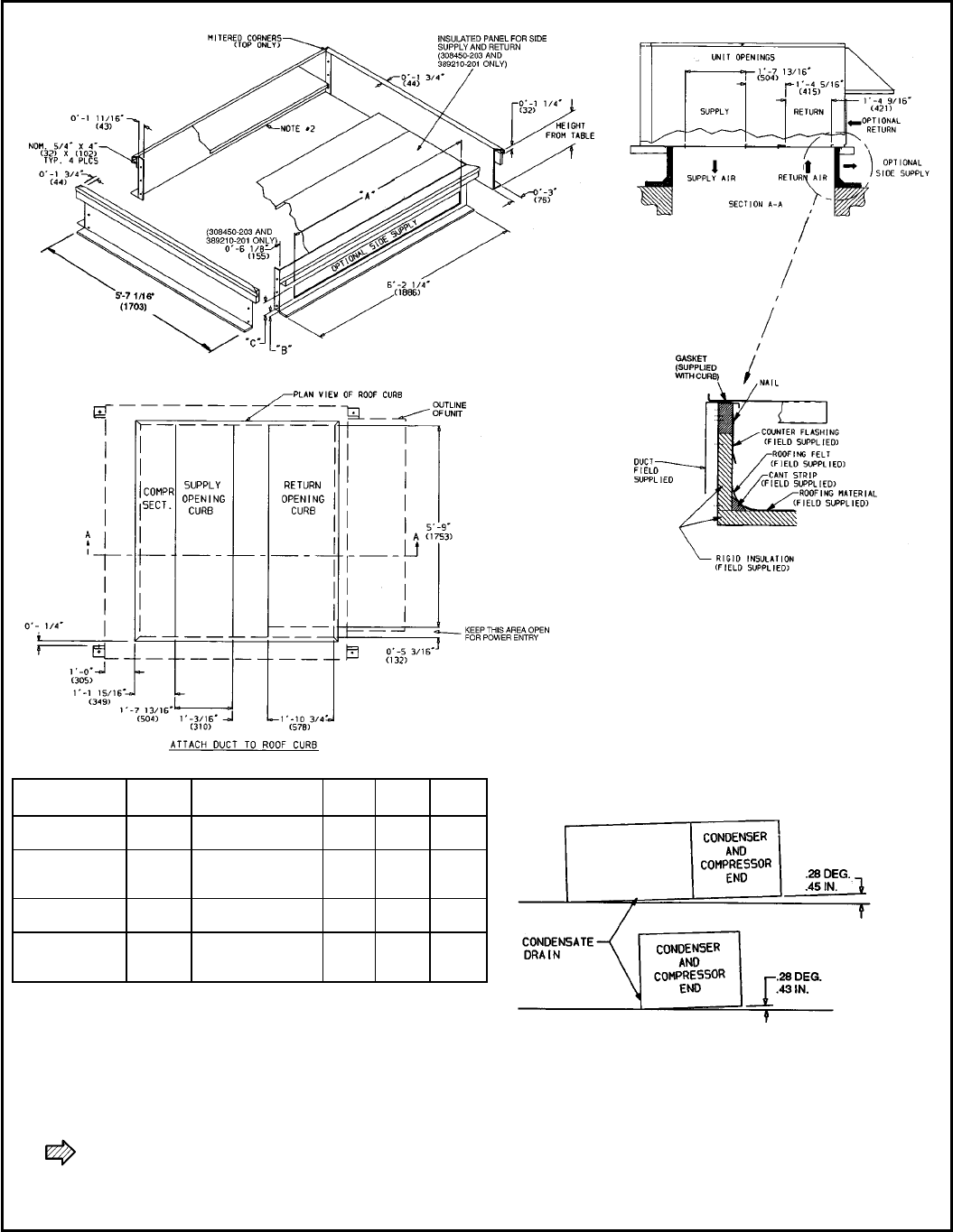
DIMENSIONAL DRAWING — HORIZONTAL AND VERTICAL ROOF CURBS
AND HORIZONTAL ADAPTER — 559F180-300
ACCESSORY
PACKAGE NO. CURB
HEIGHT DESCRIPTION ‘‘A’’ ‘‘B’’ ‘‘C’’
308450-201 18-29
(305) Standard Curb —
149High ———
308450-202 28-09
(610)
Standard Curb
for Units Requiring
High Installation ———
308450-203 28-09
(610) Horizontal Supply
and Return Curb 58-69
(1676) 08-2
1
⁄
2
9
(64) 18-69
(457)
389210-201 18-119
(584)
Pre-Assembled,
High-Static
Horizontal Adapter
68-29
(1880) 08-6
1
⁄
4
9
(159) 18-2
5
⁄
8
9
(371)
LEGEND
COMP SECT. — Compressor Section
NOTES:
1. Roof curb accessory is shipped unassembled.
2. Insulated panels,
1
⁄
2
-in. thick neoprene-coated,
2 lb density.
3. Dimensions in ( ) are in millimeters.
4. Direction of airflow.
5. Roof curb: 18 gage steel.
6. Attach all ductwork to roof curb.
NOTE: To prevent the hazard of stagnant water build-up in the drain
pan of the indoor-air section, unit can only be pitched as shown.
12
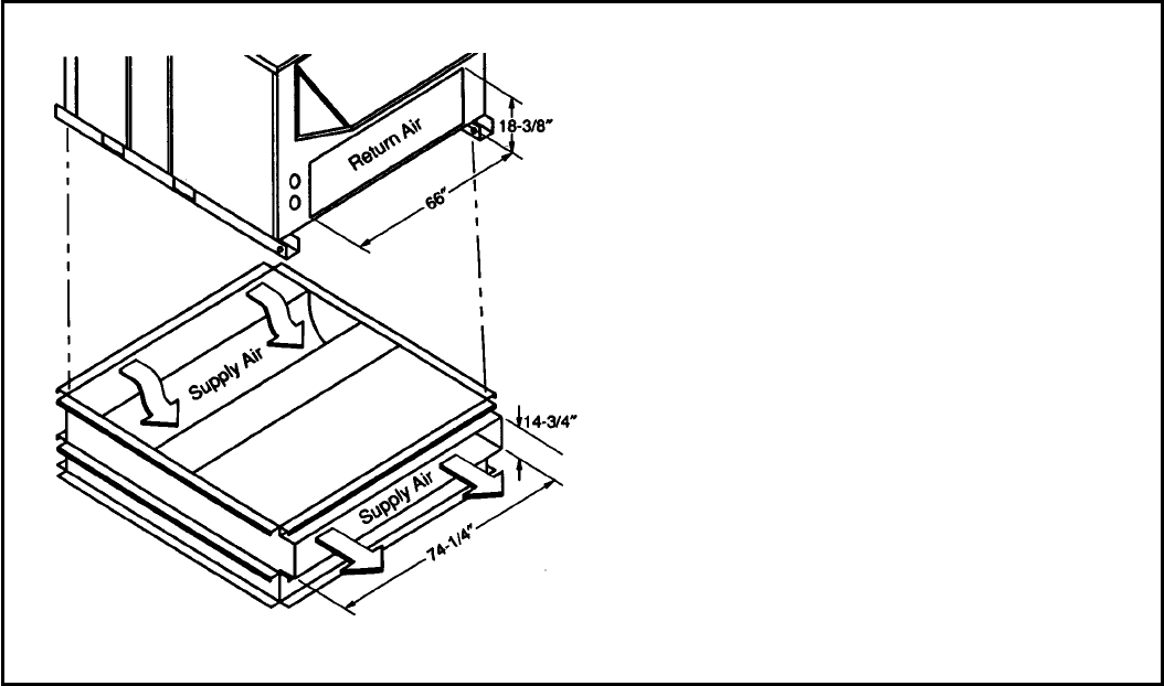
DIMENSIONAL DRAWING — HORIZONTAL ADAPTER INSTALLATION — 559F180-300
NOTE: 389210-201 is a fully factory preassembled horizontal
adapter which includes an insulated high static regain transition duct
and substantially improves fan static performance.
13

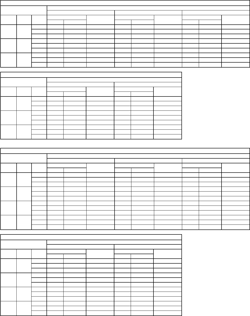
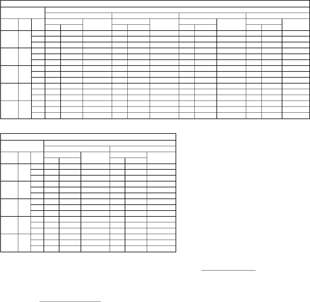
SPECIFICATIONS — 558D036-072
UNIT SIZE 036 048 060 072
NOMINAL CAPACITY (tons) 3456
OPERATING WEIGHT (lb)
Unit
Al/Al* 365 375 395 470
Economizer
Durablade 34 34 34 34
Parablade 42 42 42 42
Roof Curb† 115 115 115 115
COMPRESSOR Hermetic
Quantity
No. Cylinders (per circuit) 1
21
21
21
2
Oil (oz) 50 50 50 54
REFRIGERANT TYPE R-22
Operating Charge (lb-oz)
Circuit 1 3-6 4-11 5-13 7-10
Circuit 2 ————
CONDENSER COIL Enhanced Copper Tubes, Aluminum Lanced Fins
Rows...Fins/in. 1...17 1...17 1...17 2...17
Total Face Area (sq ft) 7.36 11.39 13.19 10.42
CONDENSER FAN Propeller Type
Nominal Cfm 4100 4100 4100 4100
Quantity...Diameter (in.) 1...22.0 1...22.0 1...22.0 1...22.0
Motor Hp...Rpm
1
⁄
4
...1100
1
⁄
4
...1100
1
⁄
4
...1100
1
⁄
4
...1100
Watts Input (Total) 325 325 325 325
EVAPORATOR COIL Enhanced Copper Tubes, Aluminum Double-Wavy Fins
Expansion Device Acutrol™ Feed Device
Rows...Fins/in. 2...15 2...15 3...15 4...15
Total Face Area (sq ft) 4.17 5.5 5.5 5.5
EVAPORATOR FAN Centrifugal Type
Quantity...Size (in.) Std 1...10 x 10 1...10 x 10 1...11 x 10 1...10 x 10
Alt 1...10 x 10 1...10 x 10 1...10 x 10 —
Type Drive Std Direct Direct Direct Belt
Alt Belt Belt Belt —
Nominal Cfm 1200 1600 2000 2400
Motor Hp Std ————
Alt ————
Maximum Continuous Bhp Std .34 .75 1.20 2.40
Alt 1.00 1.00 1.80 —
Motor Frame Size Std 48 48 48 56
Alt 48 48 48 —
Nominal Rpm High/Low Std 860/800 1075/970 1075/970 —
Alt ————
Fan Rpm Range Std — — — 1070-1460
Alt 760-1000 835-1185 900-1300 —
Motor Bearing Type Ball Ball Ball Ball
Maximum Allowable Rpm 2100 2100 2100 2100
Motor Pulley Pitch Diameter A/B (in.) Std — — — 2.8/3.8
Alt 1.9/2.9 1.9/2.9 2.4/3.4 —
Nominal Motor Shaft Diameter (in.) Std
1
⁄
21
⁄
21
⁄
25
⁄
8
Alt
1
⁄
21
⁄
21
⁄
2
—
Fan Pulley Pitch Diameter (in.) Std ———4.5
Alt 4.5 4.0 4.5 —
Belt, Quantity...Type...Length (in.) Std — — — 1...A...40
Alt 1...A...34 1...A...34 1...A...39 —
Pulley Center Line Distance (in.) Std — — — 14.7-15.5
Alt 10.0-12.4 10.0-12.4 14.7-15.5 —
Speed Change per Full Turn of Std ———80
Movable Pulley Flange (rpm) Alt 48 70 80 —
Movable Pulley Maximum Full Turns Std ——— 5
From Closed Position Alt 555—
Factory Setting Std ——— 3
Alt 333—
Factory Speed Setting (rpm) Std — — — 1225
Alt 856 975 1060 —
Fan Shaft Diameter at Pulley (in.)
1
⁄
21
⁄
21
⁄
21
⁄
2
HIGH-PRESSURE SWITCH (psig)**
Standard Compressor Internal Relief 450±50 500±50
Cutout 428 428
Reset (Auto.) 320 320
LOW-PRESSURE SWITCH (psig)**
Cutout 7±3
Reset (Auto.) 22±7
FREEZE PROTECTION THERMOSTAT (F)**
Opens 30±5
Closes 45±5
OUTDOOR-AIR INLET SCREENS Cleanable
Quantity...Size (in.) 1...20 x 24 x 1
RETURN-AIR FILTERS Throwaway
Quantity...Size (in.) 2...16 x 25 x 2
LEGEND
Al — Aluminum
Bhp — Brake Horsepower
FIOP — Factory-Installed Option
TXV — Thermostatic Expansion Valve
*Evaporator coil fins/condenser coil fins.
†Weight of 14-in. roof curb.
**Requires the accessory controls upgrade kit.
††Circuit 1 consists of lower portion of both the condenser and evaporator coils, and
Circuit 2 consists of the upper portion of both coils.
\The 559F300 units require 2-in. industrial-grade filters capable of handling face ve-
locities up to 625 ft/min (such as American Air Filter no. 5700 or equivalent).
NOTE: The 036-150 units have a loss-of-charge/low-pressure switch (accessory or op-
tion) located in the liquid line. The 180-300 units have a low-pressure switch (standard)
located on the suction side.
14

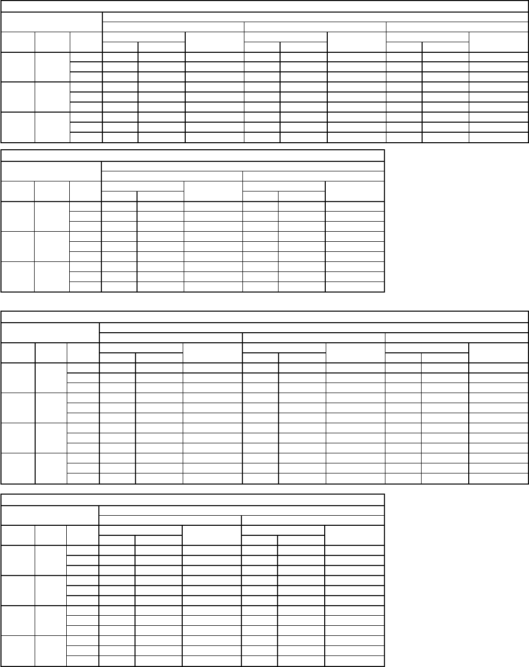
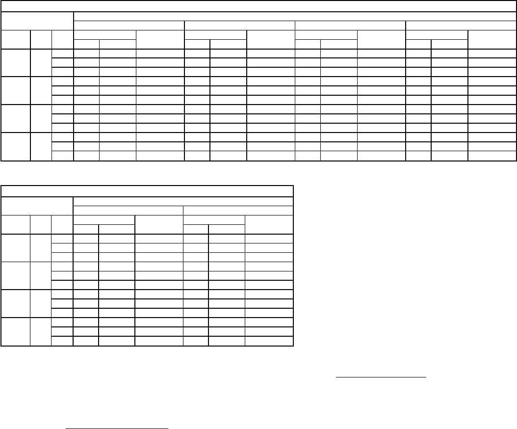
SPECIFICATIONS — 558D090-150
UNIT SIZE 090 102 120 150
NOMINAL CAPACITY (tons) 7
1
⁄
2
8
1
⁄
2
10 12
1
⁄
2
OPERATING WEIGHT (lb)
Unit
Al/Al* 755 760 915 930
Economizer
Durablade 44 44 44 44
Parablade 62 62 62 62
Roof Curb† 143 143 143 143
COMPRESSOR Hermetic
Quantity
No. Cylinders (per circuit) 2
22
22
22
2
Oil (oz) 50 ea 50 ea 50 ea 54 ea
REFRIGERANT TYPE R-22
Operating Charge (lb-oz)
Circuit 1 4-13 6-14 5-13 9-6
Circuit 2 4-14 6-3 5-14 9-0
CONDENSER COIL Enhanced Copper Tubes, Aluminum Lanced Fins
Rows...Fins/in. 1...17 2...17 2...17 2...17
Total Face Area (sq ft) 20.50 18.00 17.42 25.00
CONDENSER FAN Propeller Type
Nominal Cfm 6500 6500 7000 7000
Quantity...Diameter (in.) 2...22 2...22 2...22 2...22
Motor Hp...Rpm
1
⁄
4
...1100
1
⁄
4
...1100
1
⁄
4
...1100
1
⁄
4
...1100
Watts Input (Total) 600 600 600 600
EVAPORATOR COIL Enhanced Copper Tubes, Aluminum Double-Wavy Fins
Expansion Device Acutrol™ Feed Device
Rows...Fins/in. 3...15 3...15 3...15 4...15
Total Face Area (sq ft) 8.0 8.0 10.0 11.1
EVAPORATOR FAN Centrifugal Type
Quantity...Size (in.) Std 1...15 x 15 1...15 x 15 1...15 x 15 1...15 x 15
Alt 1...15 x 15 — 1...15 x 15 1...15 x 15
Type Drive Std Belt Belt Belt Belt
Alt Belt — Belt Belt
Nominal Cfm 3000 3400 4000 5000
Motor Hp Std ————
Alt ————
Maximum Continuous Bhp Std 2.40 2.40 2.40 4.20
Alt — — 2.90 5.25
Motor Frame Size Std 56 56 56 56
Alt — — 56 56
Nominal Rpm High/Low Std ————
Alt ————
Fan Rpm Range Std 590-840 685-935 685-935 860-1080
Alt 685-935 — 835-1085 900-1260
Motor Bearing Type Ball Ball Ball Ball
Maximum Allowable Rpm 2100 2100 2100 2100
Motor Pulley Pitch Diameter A/B (in.) Std 2.4/3.4 2.8/3.8 2.8/3.8 4.0/5.0
Alt 2.8/3.8 — 3.4/4.4 3.1/4.1
Nominal Motor Shaft Diameter (in.) Std
5
⁄
85
⁄
85
⁄
87
⁄
8
Alt ——
7
⁄
87
⁄
8
Fan Pulley Pitch Diameter (in.) Std 7.0 7.0 7.0 8.0
Alt 7.0 — 7.0 5.9
Belt, Quantity...Type...Length (in.) Std 1...A...49 1...A...49 1...A...49 1...A...52
Alt 1...A...49 — 1...A...49 1...BX...46
Pulley Center Line Distance (in.) Std 16.75-19.25 16.75-19.25 15.85-17.50 15.85-17.50
Alt 16.75-19.25 — 15.85-17.50 15.85-17.50
Speed Change per Full Turn of Std 50 50 50 44
Movable Pulley Flange (rpm) Alt 50 — 50 50
Movable Pulley Maximum Full Turns Std 5555
From Closed Position Alt 5—5 6
Factory Setting Std 5555
Alt 5—5 5
Factory Speed Setting (rpm) Std 590 685 685 860
Alt 685 — 835 960
Fan Shaft Diameter at Pulley (in.) 1111
HIGH-PRESSURE SWITCH (psig)**
Standard Compressor Internal Relief 450±50 500±50
Cutout 428 428
Reset (Auto.) 320 320
LOW-PRESSURE SWITCH (psig)**
Cutout 7±3
Reset (Auto.) 22±7
FREEZE PROTECTION THERMOSTAT (F)**
Opens 30±5
Closes 45±5
OUTDOOR-AIR INLET SCREENS Cleanable
Quantity...Size (in.) 1...20 x 25 x 1
1...16 x 25 x 1
RETURN-AIR FILTERS Throwaway
Quantity...Size (in.) 4...16 x 20 x 2 4...16 x 20 x 2 4...20 x 20 x 2 4...20 x 20 x 2
LEGEND
Al — Aluminum
Bhp — Brake Horsepower
FIOP — Factory-Installed Option
TXV — Thermostatic Expansion Valve
*Evaporator coil fins/condenser coil fins.
†Weight of 14-in. roof curb.
**Requires the accessory controls upgrade kit.
††Circuit 1 consists of lower portion of both the condenser and evaporator coils, and
Circuit 2 consists of the upper portion of both coils.
\The 559F300 units require 2-in. industrial-grade filters capable of handling face ve-
locities up to 625 ft/min (such as American Air Filter no. 5700 or equivalent).
NOTE: The 036-150 units have a loss-of-charge/low-pressure switch (accessory or op-
tion) located in the liquid line. The 180-300 units have a low-pressure switch (standard)
located on the suction side.
15

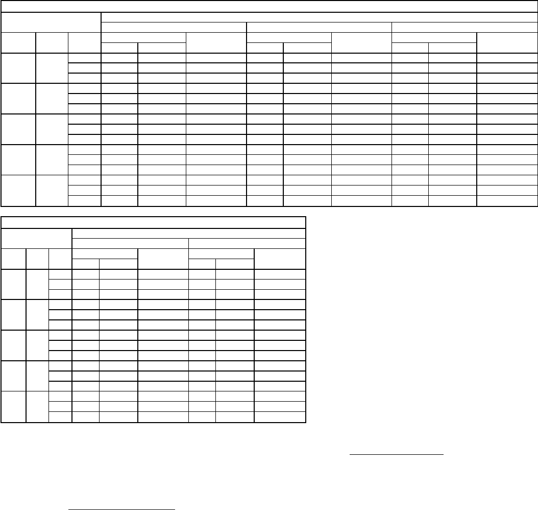
SPECIFICATIONS — 559F180-300
UNIT SIZE 180 216 240 300
208/230,460 V 575 V
NOMINAL CAPACITY (tons) 15 18 20 25
OPERATING WEIGHT (lb)
Unit
Al/Al* 1500 2050 2100 2150
Economizer 110 110 110 110
Roof Curb† 200 200 200 200
COMPRESSOR Semi-Hermetic
Quantity
No. Cylinders (per circuit) 1
62
62
62
6
Oil (oz) 115 115,88 115 ea 128 ea
REFRIGERANT TYPE R-22
Operating Charge (lb-oz)
Circuit 1†† 19-4 13-4 12-13 16-12
Circuit 2 — 11-0 12-13 15-12
CONDENSER COIL Enhanced Copper Tubes, Aluminum Lanced Fins
Rows...Fins/in. 2...17 3...15 3...15 4...15
Total Face Area (sq ft) 22.2 22.2 22.2 22.2
CONDENSER FAN Propeller Type
Nominal Cfm 10,500 14,200 14,200
Quantity...Diameter (in.) 3...22 2...30 2...30
Motor Hp...Rpm
1
⁄
2
...1050 1...1075 1...1075
Watts Input (Total) 1100 3400 3400
EVAPORATOR COIL Copper Tubes, Aluminum or Copper Plate Fins
Expansion Device TXV Acutrol™ Feed Device
Rows...Fins/in. 2...17 3...17 3...15 4...15
Total Face Area (sq ft) 17.9 17.9 17.9 17.9
EVAPORATOR FAN Centrifugal Type
Quantity...Size (in.) 2...10 x 10 2...10 x 10 2...12 x 12 2...12 x 12 2...12 x 12
Type Drive Belt Belt Belt Belt Belt
Nominal Cfm 6000 6000 7200 8000 10,000
Motor Hp 3.7 3 5 7
1
⁄
2
10
Maximum Continuous Bhp 4.25 3.45 5.90 8.7 [208/230,575 v]
9.5 [460 v] 10.26 [208/230,575 v]
11.80 [460 v]
Motor Frame Size 56H 56H 184T 213T 215T
Fan Rpm Range 1227-1559 1201-1462 1047-1251 1238-1494 1323-1579
Motor Bearing Type Ball Ball Ball Ball Ball
Maximum Allowable Rpm 1559 1550 1550 1550 1550
Motor Pulley Pitch Diameter Min/Max (in.) 3.7/4.7 4.3/5.3 4.9/5.9 5.4/6.4 5.8/7.0
Nominal Motor Shaft Diameter (in.)
7
⁄
87
⁄
8
1
1
⁄
8
1
3
⁄
8
1
3
⁄
8
Fan Pulley Pitch Diameter (in.) 5.2 6.4 8.4 7.9 7.9
Belt, Quantity...Type...Length (in.) 1...BX...42 1...BX...45 1...BX..50 1...BX..50 1...BX...51
Pulley Center Line Distance (in.) — — 13.3-14.8 14.6-15.4 14.6-15.4
Speed Change per Full Turn of 66 52 34 43 43
Movable Pulley Flange (rpm)
Movable Pulley Maximum Full Turns 556 6 6
From Closed Position
Factory Setting 4 3.5 3 3 3
Factory Speed Setting (rpm) 1293 1279 1149 1366 1451
Fan Shaft Diameter at Pulley (in.) 1
3
⁄
16
1
3
⁄
16
1
7
⁄
16
1
7
⁄
16
1
7
⁄
16
HIGH-PRESSURE SWITCH (psig)
Standard Compressor Internal Relief —
Cutout 426
Reset (Auto.) 320
LOW-PRESSURE SWITCH (psig)
Cutout 7
Reset (Auto.) 22
FREEZE PROTECTION THERMOSTAT (F)
Opens 30±5
Closes 45±5
OUTDOOR-AIR INLET SCREENS Cleanable
Quantity...Size (in.) 2...20 x 25 x 1
1...20 x 20 x 1
RETURN-AIR FILTERS Throwaway\
Quantity...Size (in.) 4...20 x 20 x 2
4...16 x 20 x 2
LEGEND
Al — Aluminum
Bhp — Brake Horsepower
FIOP — Factory-Installed Option
TXV — Thermostatic Expansion Valve
*Evaporator coil fins/condenser coil fins.
†Weight of 14-in. roof curb.
**Requires the accessory controls upgrade kit.
††Circuit 1 consists of lower portion of both the condenser and evaporator coils, and
Circuit 2 consists of the upper portion of both coils.
\The 559F300 units require 2-in. industrial-grade filters capable of handling face ve-
locities up to 625 ft/min (such as American Air Filter no. 5700 or equivalent).
NOTE: The 036-150 units have a loss-of-charge/low-pressure switch (accessory or op-
tion) located in the liquid line. The 180-300 units have a low-pressure switch (standard)
located on the suction side.
16

SELECTION PROCEDURE (With 559F180 Example)
I Determine cooling and heating requirements at design
conditions.
Given:
Cooling Capacity Required (TC) .........177,000 Btuh
Sensible Heat Capacity (SHC) ..........127,000 Btuh
Condenser Entering-Air
Temperature..................95FEdb/78 F Ewb
Indoor-Air Temperature ...........80FEdb/67 F Ewb
Evaporator Air Quantity ..................6,000 cfm
External Static Pressure .................0.66 in. wg
Heating Capacity ......................76,000 Btuh
Power Supply (V-Ph-Hz) ..................230-3-60
Edb — Entering dry bulb
Ewb — Entering wet bulb
II Select unit based on required cooling capacity.
Enter Gross Cooling Capacities table on page 22 for
559F180 at condenser entering dry bulb temperature
95 F, air entering evaporator at 6000 cfm, 80 F edb and
67 F ewb. The 559F180 unit will provide a total cooling ca-
pacity of 188,000 Btuh, a sensible heating capacity of
136,000 Btuh and a total unit kW of 17.8 kW. For
evaporator-air temperatures other than 80 F edb, calculate
sensible heat capacity correction, as required, using the
formula in the notes following the Cooling Capacities
tables.
NOTE: Unit ratings are gross capacities and do not include
the effect of evaporator-fan motor heat. To calculate net
capacities, see Step V.
III Select electric heat.
Heating load required is 76,000 Btuh.
76,000 Btuh = kW of heat required
3,412 Btu/kW = 22.3 kW
Enter the Electric Resistance Heater Data table for the
559F180 on page 64 at 230-3-60. The 34 kW electric
heater most closely satisfies the heat required.
IV Determine fan speed and motor horsepower require-
ments at design conditions.
Enter Accessory/FIOP Static Pressure Drop table on
page 47 at selected unit size and heater kW.
Find that at given air quantity (6000 cfm), pressure loss is
.09 in. wg.
Before entering the Air Delivery tables, calculate the total
static pressure required based on unit components. From
the given and the Accessory/FIOP Pressure table
(page 47) find:
External static pressure 0.66 in. wg
34 kW Heater static pressure 0.09 in. wg
Total static pressure 0.75 in. wg
Enter Air Delivery table for unit 559F180 on page 42. In-
terpolate to see that at 6000 cfm and 0.75 in. wg external
static pressure, the fan speed is 1184 rpm, the watts are
2631, and the bhp is 2.96. The standard motor with a field-
supplied drive is suitable.
V Determine net cooling capacity.
Cooling capacities are gross capacities and do not include
indoor (evaporator) fan motor (IFM) heat.
Use the watts input power to the motor from the Air Deliv-
ery table (calculated in Section IV above).
IFM watts = 2631
Determine net cooling capacity using the following
formula:
Net capacity = Gross capacity − IFM heat
Btuh
= 188,000 Btuh − 2631 watts (3.412 )
Watts
= 188,000 Btuh − 8977 Btuh
= 179,023 Btuh
Net sensible capacity = 136,000 Btuh − 8977 Btuh
= 127,023 Btuh
As a result of the given conditions, the 559F180 unit is the
correct selection.
17
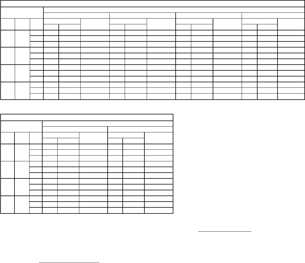
GROSS COOLING CAPACITIES
558D036 (3 TON)
Air Entering
Evaporator Air Entering Condenser (F)
75 85 95
Cfm BF Ewb
(F) Capacity MBtuh Compressor
kW Capacity MBtuh Compressor
kW Capacity MBtuh Compressor
kW
Total Sensible Total Sensible Total Sensible
900 0.11
72 42.8 20.0 2.91 40.8 19.4 3.14 38.7 18.6 3.35
67 38.9 24.5 2.81 36.9 23.7 3.01 34.9 22.9 3.21
62 35.0 28.7 2.70 33.3 27.9 2.90 31.4 27.0 3.09
1200 0.14
72 44.8 21.8 2.99 42.5 21.0 3.20 40.4 20.3 3.42
67 40.8 27.5 2.88 38.7 26.8 3.08 36.6 26.0 3.29
62 37.0 32.8 2.78 35.0 31.8 2.97 33.0 30.9 3.16
1500 0.17
72 45.8 23.0 3.02 43.6 22.6 3.24 41.4 22.0 3.47
67 41.9 30.0 2.92 39.9 29.7 3.14 37.6 28.8 3.35
62 38.2 36.0 2.82 36.1 35.1 3.02 34.1 34.0 3.22
558D036 (3 TON) (cont)
Air Entering
Evaporator Air Entering Condenser (F)
105 115
Cfm BF Ewb
(F) Capacity MBtuh Compressor
kW Capacity MBtuh Compressor
kW
Total Sensible Total Sensible
900 0.11
72 36.5 17.8 3.55 34.3 17.0 3.76
67 32.8 22.1 3.41 30.7 21.3 3.60
62 29.2 25.9 3.27 26.9 24.8 3.45
1200 0.14
72 38.1 19.6 3.63 35.7 19.0 3.84
67 34.3 25.2 3.49 32.1 24.4 3.68
62 30.9 29.8 3.35 28.8 28.8 3.54
1500 0.17
72 39.0 21.2 3.68 36.5 20.5 3.88
67 35.2 28.0 3.54 32.9 27.1 3.74
62 32.4 32.3 3.43 30.6 30.6 3.64
558D048 (4 TON)
Air Entering
Evaporator Air Entering Condenser (F)
75 85 95
Cfm BF Ewb
(F) Capacity MBtuh Compressor
kW Capacity MBtuh Compressor
kW Capacity MBtuh Compressor
kW
Total Sensible Total Sensible Total Sensible
1200 0.12
72 57.9 27.2 4.07 55.7 26.4 4.40 52.9 25.5 4.70
67 53.1 33.3 3.93 50.8 32.5 4.24 48.1 31.5 4.54
62 48.3 39.2 3.79 45.3 37.8 4.08 42.5 36.4 4.36
1600 0.15
72 60.4 29.4 4.17 57.7 28.4 4.47 55.2 27.6 4.78
67 55.9 37.2 4.03 53.4 36.7 4.35 50.5 35.6 4.63
62 51.3 44.8 3.90 48.5 43.6 4.20 45.7 42.2 4.47
2000 0.18
72 62.2 31.4 4.24 59.4 30.5 4.54 56.7 29.7 4.87
67 57.3 40.3 4.08 55.0 40.3 4.42 52.0 39.2 4.70
62 52.9 49.1 3.96 50.2 47.9 4.25 47.4 46.7 4.56
558D048 (4 TON) (cont)
Air Entering
Evaporator Air Entering Condenser (F)
105 115
Cfm BF Ewb
(F) Capacity MBtuh Compressor
kW Capacity MBtuh Compressor
kW
Total Sensible Total Sensible
1200 0.12
72 50.1 24.4 5.00 47.3 23.4 5.30
67 45.3 30.3 4.81 42.6 29.2 5.07
62 39.8 35.1 4.62 37.2 33.7 4.88
1600 0.15
72 52.3 26.7 5.10 49.3 25.9 5.42
67 47.6 34.5 4.91 44.6 33.3 5.19
62 42.8 40.7 4.73 40.0 39.3 4.99
2000 0.18
72 53.6 28.8 5.17 50.5 27.8 5.48
67 48.9 38.1 4.99 45.9 37.1 5.28
62 44.9 44.6 4.84 42.4 42.4 5.12
LEGEND
BF — Bypass Factor
Edb — Entering Dry Bulb
Ewb — Entering Wet Bulb
kW — Compressor Motor Power Input
MBtuh — Btuh in thousands
NOTES:
1. Direct interpolation is permissible. Do not extrapolate.
2. The following formulas may be used:
sensible capacity (1000 x MBtuh)
t=t –
ldb edb 1.10 x cfm
t = Wet-bulb temperature corresponding to enthalpy of air
lwb leaving evaporator coil (h )
lwb
total capacity (1000 x MBtuh)
h=h –
lwb ewb 4.5 x cfm
Where: h = Enthalpy of air entering evaporator coil.
ewb
3. The sensible heat capacity is based on 80 F entering dry-bulb (edb) tempera-
ture of air entering evaporator coil.
Below 80 F edb, subtract (corr factor x cfm) from the sensible heat capacity.
Above 80 F edb, add (corr factor x cfm) to the sensible heat capacity.
Correction Factor = 1.10 x (1 – BF) x (edb – 80).
18
GROSS COOLING CAPACITIES (cont)
558D060 (5 TON)
Air Entering
Evaporator Air Entering Condenser (F)
75 85 95
Cfm BF Ewb
(F) Capacity MBtuh Compressor
kW Capacity MBtuh Compressor
kW Capacity MBtuh Compressor
kW
Total Sensible Total Sensible Total Sensible
1500 0.07
72 71.0 33.9 5.04 69.2 33.4 5.50 65.5 32.1 5.88
67 63.8 41.5 4.82 61.0 40.5 5.27 56.6 38.8 5.62
62 55.4 47.9 4.62 54.2 47.3 5.02 50.4 45.6 5.37
2000 0.09
72 74.5 37.4 5.20 72.9 37.0 5.66 69.4 35.8 6.01
67 67.2 47.4 4.97 65.6 46.9 5.41 60.9 45.3 5.76
62 59.2 55.8 4.76 57.2 54.9 5.18 53.1 52.6 5.53
2500 0.12
72 76.5 40.6 5.29 75.2 40.1 5.75 71.2 39.1 6.12
67 69.7 52.8 5.06 68.1 52.3 5.50 63.3 50.9 5.87
62 62.1 61.8 4.87 61.5 61.3 5.29 57.8 57.8 5.67
558D060 (5 TON) (cont)
Air Entering
Evaporator Air Entering Condenser (F)
105 115
Cfm BF Ewb
(F) Capacity MBtuh Compressor
kW Capacity MBtuh Compressor
kW
Total Sensible Total Sensible
1500 0.07
72 61.9 30.8 6.25 58.2 29.5 6.63
67 53.1 37.5 5.99 49.7 36.1 6.35
62 47.1 44.1 5.72 43.7 42.5 6.08
2000 0.09
72 65.4 34.5 6.38 61.4 33.2 6.75
67 56.6 43.7 6.13 52.3 42.1 6.49
62 50.5 50.2 5.91 47.8 47.8 6.29
2500 0.12
72 67.1 37.9 6.50 63.0 36.7 6.88
67 58.8 49.3 6.23 54.3 47.6 6.59
62 54.5 54.5 6.06 51.2 51.2 6.46
558D072 (6 TON)
Air Entering
Evaporator Air Entering Condenser (F)
75 85 95
Cfm BF Ewb
(F) Capacity MBtuh Compressor
kW Capacity MBtuh Compressor
kW Capacity MBtuh Compressor
kW
Total Sensible Total Sensible Total Sensible
1800 0.06
72 86.6 42.2 5.48 84.1 41.1 6.17 81.6 40.6 6.86
67 80.0 52.3 5.33 77.4 51.3 6.00 74.7 50.3 6.67
62 73.6 62.2 5.21 71.0 61.1 5.85 68.5 60.0 6.49
2100 0.08
72 87.8 43.0 5.69 84.0 41.7 6.21 81.0 40.8 6.78
67 80.3 53.9 5.50 77.2 53.1 6.04 73.5 51.8 6.54
62 73.3 64.8 5.35 70.2 63.7 5.85 66.6 62.2 6.33
2400 0.09
72 90.8 46.5 5.59 87.8 45.5 6.27 84.8 44.6 6.95
67 84.1 59.6 5.44 81.2 58.6 6.11 78.2 57.6 6.77
62 77.2 71.6 5.29 74.5 70.3 5.94 71.8 69.1 6.59
3000 0.11
72 93.2 50.1 5.66 90.1 49.4 6.35 87.0 48.7 7.03
67 86.6 66.4 5.51 83.5 65.4 6.19 80.4 64.5 6.86
62 79.7 78.7 5.35 77.3 76.7 6.02 74.8 74.7 6.69
558D072 (6 TON) (cont)
Air Entering
Evaporator Air Entering Condenser (F)
105 115
Cfm BF Ewb
(F) Capacity MBtuh Compressor
kW Capacity MBtuh Compressor
kW
Total Sensible Total Sensible
1800 0.06
72 78.4 39.4 7.60 75.1 38.1 8.36
67 71.8 49.2 7.39 68.7 47.9 8.14
62 65.6 58.7 7.20 62.5 57.2 7.93
2100 0.08
72 76.8 39.4 7.30 72.5 37.9 7.81
67 69.7 50.3 7.05 65.5 48.7 7.53
62 63.0 60.3 6.80 59.4 58.4 7.26
2400 0.09
72 81.6 43.5 7.72 78.0 42.3 8.49
67 74.9 56.4 7.50 71.5 55.1 8.25
62 68.9 67.4 7.31 66.1 65.5 8.06
3000 0.11
72 83.3 47.4 7.77 79.5 46.3 8.55
67 76.9 63.1 7.59 73.3 61.6 8.33
62 72.1 72.0 7.41 69.3 69.2 8.18
19

GROSS COOLING CAPACITIES (cont)
558D090 (7
1
⁄
2
TON)
Air Entering
Evaporator Air Entering Condenser (F)
75 85 95
Cfm BF Ewb
(F) Capacity MBtuh Compressor
kW Capacity MBtuh Compressor
kW Capacity MBtuh Compressor
kW
Total Sensible Total Sensible Total Sensible
2250 0.07
72 102.8 49.4 7.14 98.6 48.0 7.66 93.8 46.4 8.18
67 94.8 61.8 6.82 90.2 60.2 7.34 85.2 58.2 7.84
62 86.2 73.2 6.50 81.6 71.2 7.00 76.6 68.8 7.48
2800 0.09
72 105.8 52.6 7.28 101.8 51.6 7.82 97.0 50.2 8.36
67 98.2 67.8 6.98 93.6 66.4 7.50 88.4 64.6 8.00
62 90.0 81.6 6.68 85.2 79.6 7.18 80.0 77.2 7.64
3000 0.10
72 106.4 53.6 7.32 102.6 52.8 7.86 97.6 51.4 8.40
67 99.0 69.8 7.04 94.4 68.6 7.54 89.0 66.8 8.04
62 90.8 84.0 6.72 86.0 82.0 7.22 81.2 79.0 7.70
3750 0.12
72 109.2 58.2 7.46 104.6 56.8 7.98 99.4 55.6 8.50
67 101.6 77.4 7.18 96.8 76.0 7.68 91.2 74.4 8.16
62 93.6 92.2 6.86 89.6 89.4 7.40 85.2 85.2 7.92
558D090 (7
1
⁄
2
TON) (cont)
Air Entering
Evaporator Air Entering Condenser (F)
105 115
Cfm BF Ewb
(F) Capacity MBtuh Compressor
kW Capacity MBtuh Compressor
kW
Total Sensible Total Sensible
2250 0.07
72 88.4 44.6 8.68 82.8 42.6 9.16
67 79.8 56.2 8.30 73.8 53.8 8.78
62 70.8 66.0 7.98 66.0 63.2 8.42
2800 0.09
72 91.0 48.2 8.80 85.2 46.4 9.30
67 82.8 62.6 8.46 76.8 60.4 8.92
62 74.6 74.2 8.14 69.6 69.6 8.64
3000 0.10
72 91.6 49.4 8.86 85.6 47.8 9.34
67 83.4 64.8 8.50 77.4 62.6 8.96
62 76.0 75.6 8.20 71.0 71.0 8.72
3750 0.12
72 93.8 54.2 8.98 87.6 52.8 9.48
67 85.4 72.4 8.64 79.4 70.4 9.10
62 80.6 80.6 8.42 76.0 75.8 8.94
558D102 (8
1
⁄
2
TON)
Air Entering
Evaporator Air Entering Condenser (F)
75 85 95
Cfm BF Ewb
(F) Capacity MBtuh Compressor
kW Capacity MBtuh Compressor
kW Capacity MBtuh Compressor
kW
Total Sensible Total Sensible Total Sensible
2550 0.080
72 116.6 71.9 7.77 113.3 54.0 8.46 109.1 77.4 8.90
67 108.4 61.9 7.57 104.2 67.7 8.22 99.3 65.9 8.97
62 99.0 75.9 7.38 94.0 80.4 7.96 87.3 52.6 8.68
3000 0.10
72 119.2 75.2 7.86 115.7 56.3 5.54 111.2 55.0 8.99
67 111.3 65.1 10.68 106.9 72.5 8.31 102.0 70.9 9.06
62 101.8 81.4 7.44 97.0 87.1 8.04 91.4 84.9 8.79
3400 0.110
72 120.1 80.5 7.89 117.2 58.2 8.60 112.5 57.1 9.06
67 112.8 68.0 6.72 108.7 76.4 8.38 103.6 75.1 9.12
62 103.6 85.6 7.51 98.8 92.5 8.12 93.7 90.3 8.86
4250 0.135
72 122.3 32.7 7.97 120.1 62.9 8.72 115.3 62.2 4.76
67 114.8 73.9 7.80 111.0 84.2 8.48 105.8 83.2 9.24
62 106.3 94.4 7.60 101.8 101.0 8.23 107.4 97.3 9.00
558D102 (8
1
⁄
2
TON) (cont)
Air Entering
Evaporator Air Entering Condenser (F)
105 115
Cfm BF Ewb
(F) Capacity MBtuh Compressor
kW Capacity MBtuh Compressor
kW
Total Sensible Total Sensible
2550 0.080
72 103.3 50.5 9.74 97.7 48.7 10.33
67 94.0 54.0 9.43 87.9 61.7 9.97
62 81.4 74.5 9.08 75.9 71.9 9.61
3000 0.10
72 105.9 53.5 9.85 99.9 51.8 10.46
67 96.3 69.1 9.54 90.4 66.9 10.10
62 84.6 81.4 9.21 78.8 78.1 9.75
3400 0.110
72 107.4 55.8 9.92 101.3 54.0 10.54
67 97.7 73.1 9.60 91.8 71.2 10.18
62 87.9 86.6 9.29 82.4 82.3 9.88
4250 0.135
72 109.4 60.4 10.03 102.9 58.5 10.61
67 99.9 81.4 9.72 93.8 79.4 10.30
62 92.8 92.8 9.48 88.3 88.2 10.10
(See Legend and Notes on page 18.)
20
GROSS COOLING CAPACITIES (cont)
558D120 (10 TON)
Air Entering
Evaporator Air Entering Condenser (F)
75 85 95
Cfm BF Ewb
(F) Capacity MBtuh Compressor
kW Capacity MBtuh Compressor
kW Capacity MBtuh Compressor
kW
Total Sensible Total Sensible Total Sensible
3000 0.095
72 135.8 66.8 9.76 130.0 64.3 10.41 124.1 62.2 11.13
67 124.8 82.6 9.41 119.6 80.5 10.07 113.7 78.4 10.78
62 112.0 97.4 9.10 104.0 93.8 9.74 96.7 90.0 10.40
4000 0.125
72 142.4 73.2 10.00 136.0 71.1 10.67 129.5 69.1 11.38
67 130.6 93.4 9.61 125.0 91.7 10.28 118.9 89.8 10.99
62 119.8 112.7 9.27 114.5 110.2 9.94 106.9 105.9 10.63
5000 0.150
72 146.5 79.7 10.17 140.0 77.5 10.84 132.8 74.9 11.52
67 134.2 104.4 9.75 127.9 101.8 10.41 122.0 100.1 11.14
62 123.7 123.1 9.41 118.8 118.7 10.09 114.1 114.0 10.83
558D120 (10 TON) (cont)
Air Entering
Evaporator Air Entering Condenser (F)
105 115
Cfm BF Ewb
(F) Capacity MBtuh Compressor
kW Capacity MBtuh Compressor
kW
Total Sensible Total Sensible
3000 0.095
72 118.1 60.4 11.93 115.0 59.4 12.26
67 104.6 74.9 11.52 98.0 72.4 11.82
62 87.9 85.2 11.10 84.2 83.4 11.40
4000 0.125
72 122.7 66.9 12.13 120.0 66.4 12.48
67 111.8 87.7 11.74 103.8 84.8 12.06
62 98.5 98.5 11.41 93.4 93.4 11.78
5000 0.150
72 126.0 73.1 12.27 122.6 72.8 12.60
67 115.1 98.3 11.89 109.8 96.6 12.20
62 108.0 108.0 11.65 102.8 102.8 12.00
558D150 (12
1
⁄
2
TON)
Air Entering
Evaporator Air Entering Condenser (F)
75 85 95
Cfm BF Ewb
(F) Capacity MBtuh Compressor
kW Capacity MBtuh Compressor
kW Capacity MBtuh Compressor
kW
Total Sensible Total Sensible Total Sensible
3750 0.08
72 175.6 85.7 11.16 169.3 83.9 12.15 161.9 81.4 13.12
67 162.2 107.3 10.85 155.7 104.8 11.78 148.9 102.0 12.72
62 149.2 128.0 10.57 140.6 124.0 11.42 132.0 119.8 12.28
4500 0.09
72 181.0 91.4 11.32 174.2 89.6 12.31 166.8 87.0 13.30
67 167.5 116.2 11.00 160.7 113.9 11.94 153.5 111.1 12.89
62 154.2 140.3 10.69 147.0 137.0 11.58 139.1 133.2 12.46
5000 0.10
72 182.9 94.2 11.37 176.9 92.7 12.39 169.5 90.7 13.40
67 170.2 122.2 11.07 163.0 119.7 12.01 155.7 117.3 12.97
62 156.4 146.5 10.73 149.7 143.6 11.63 142.8 140.2 12.56
6250 0.12
72 187.2 102.1 11.49 181.5 100.9 12.52 173.2 98.3 13.54
67 174.7 135.3 11.19 167.3 133.4 12.14 159.5 130.8 13.11
62 161.8 160.7 10.87 155.8 155.6 11.82 149.6 149.6 12.78
558D150 (12
1
⁄
2
TON) (cont)
Air Entering
Evaporator Air Entering Condenser (F)
105 115
Cfm BF Ewb
(F) Capacity MBtuh Compressor
kW Capacity MBtuh Compressor
kW
Total Sensible Total Sensible
3750 0.08
72 154.9 79.0 14.16 146.2 76.1 15.09
67 141.3 99.2 13.66 132.2 95.7 14.57
62 123.0 115.5 13.17 113.1 110.3 14.07
4500 0.09
72 158.8 84.5 14.31 150.5 81.7 15.30
67 145.4 108.2 13.82 137.0 105.2 14.76
62 130.2 128.1 13.35 122.4 122.3 14.25
5000 0.10
72 160.9 87.8 14.38 152.3 85.0 15.37
67 147.6 114.3 13.91 139.4 111.6 14.87
62 135.0 134.9 13.48 127.8 127.7 14.43
6250 0.12
72 165.3 96.6 14.58 155.2 92.9 15.49
67 151.2 127.8 14.07 142.7 125.0 15.02
62 143.2 143.1 13.77 136.0 135.8 14.73
(See Legend and Notes on page 22.)
21
GROSS COOLING CAPACITIES (cont)
559F180 (15 TON)
Air Entering
Evaporator Air Entering Condenser (F)
75 85 95
Cfm BF Ewb
(F) Capacity MBtuh Compressor
kW Capacity MBtuh Compressor
kW Capacity MBtuh Compressor
kW
Total Sensible Total Sensible Total Sensible
4500 0.08
72 212.0 101.0 15.20 205.0 98.5 16.60 197.0 95.8 18.00
67 195.0 126.0 14.70 188.0 123.0 16.10 180.2 120.0 17.40
62 179.0 148.0 14.20 171.0 145.0 15.50 162.0 141.0 16.70
5250 0.10
72 216.0 105.0 15.40 210.0 103.0 16.80 202.0 101.0 18.20
67 200.0 133.0 14.90 19.30 131.0 16.30 184.0 128.0 17.60
62 183.0 161.0 14.90 176.0 156.0 15.70 167.0 152.0 16.90
6000 0.11
72 219.0 109.0 15.50 212.0 108.0 16.90 205.0 105.0 18.40
67 204.0 141.0 15.10 196.0 138.0 16.40 188.0 136.0 17.80
62 187.0 170.0 14.60 179.0 167.0 15.90 171.0 164.0 17.10
6750 0.12
72 223.0 115.0 15.70 215.0 113.0 17.10 206.0 110.0 18.40
67 205.0 152.0 15.10 199.0 145.0 16.50 191.0 143.0 17.90
62 189.0 179.0 14.70 182.0 176.0 16.00 174.0 172.0 17.30
7500 0.14
72 224.0 118.0 15.70 216.0 116.0 17.10 209.0 115.0 18.60
67 207.0 157.0 15.20 199.0 154.0 16.60 193.0 150.0 18.00
62 193.0 187.0 14.80 185.0 184.0 16.10 178.0 178.0 17.50
559F180 (15 TON) (cont)
Air Entering
Evaporator Air Entering Condenser (F)
105 115
Cfm BF Ewb
(F) Capacity MBtuh Compressor
kW Capacity MBtuh Compressor
kW
Total Sensible Total Sensible
4500 0.08
72 190.0 93.3 19.40 180.0 90.0 20.80
67 172.0 117.0 18.70 161.0 112.0 19.90
62 152.0 136.0 17.90 142.0 131.0 19.10
5250 0.10
72 194.0 98.0 19.60 185.0 95.4 21.00
67 176.0 125.0 18.90 166.0 121.0 20.10
62 157.0 148.0 18.10 146.0 142.0 19.30
6000 0.11
72 197.0 103.0 19.80 187.0 100.0 21.20
67 179.0 133.0 19.10 170.0 130.0 20.30
62 161.0 158.0 18.40 151.0 151.0 19.60
6750 0.12
72 199.0 107.0 19.90 190.0 105.0 21.40
67 182.0 140.0 19.20 172.0 137.0 20.50
62 166.0 166.0 18.60 158.0 158.0 19.90
7500 0.14
72 200.0 112.0 20.00 191.0 109.0 21.50
67 183.0 148.0 19.30 173.0 144.0 20.60
62 171.0 171.0 18.80 163.0 163.0 20.10
LEGEND
BF — Bypass Factor
Edb — Entering Dry Bulb
Ewb — Entering Wet Bulb
kW — Compressor Motor Power Input
MBtuh — Btuh in thousands
NOTES:
1. Direct interpolation is permissible. Do not extrapolate.
2. The following formulas may be used:
sensible capacity (1000 x MBtuh)
t=t –
ldb edb 1.10 x cfm
t = Wet-bulb temperature corresponding to enthalpy of air
lwb leaving evaporator coil (h )
lwb
total capacity (1000 x MBtuh)
h=h –
lwb ewb 4.5 x cfm
Where: h = Enthalpy of air entering evaporator coil.
ewb
3. The sensible heat capacity is based on 80 F entering dry-bulb (edb) tempera-
ture of air entering evaporator coil.
Below 80 F edb, subtract (corr factor x cfm) from the sensible heat capacity.
Above 80 F edb, add (corr factor x cfm) to the sensible heat capacity.
Correction Factor = 1.10 x (1 – BF) x (edb – 80).
22
GROSS COOLING CAPACITIES (cont)
559F216 (18 TON)
Air Entering
Evaporator Air Entering Condenser (F)
75 85 95 105
Cfm BF Ewb
(F) Capacity MBtuh Compressor
kW Capacity MBtuh Compressor
kW Capacity MBtuh Compressor
kW Capacity MBtuh Compressor
kW
Total Sensible Total Sensible Total Sensible Total Sensible
5400 0.06
72 242.0 121.6 14.72 231.0 116.8 16.27 218.5 112.5 17.83 204.3 105.1 17.75
67 219.6 151.8 14.78 208.6 146.3 16.29 196.4 141.3 17.79 187.2 135.0 17.88
62 197.3 176.3 14.71 187.3 171.5 16.26 176.0 165.6 17.73 169.4 158.6 17.93
6000 0.075
72 242.0 125.7 14.91 232.0 121.2 16.59 220.1 116.4 18.15 203.1 108.1 17.96
67 221.1 157.4 15.00 209.3 152.7 16.56 197.1 147.1 18.12 187.2 139.0 18.12
62 198.4 184.1 14.97 188.1 178.6 16.50 178.2 172.7 18.08 170.9 165.4 18.27
7200 0.085
72 241.0 135.8 15.35 231.0 128.0 17.02 219.1 122.4 18.64 203.4 115.6 18.45
67 221.0 167.7 15.43 209.5 162.9 17.05 198.2 157.6 18.71 186.5 149.2 18.62
62 201.8 196.6 15.50 191.5 189.5 17.10 181.2 181.2 18.76 172.8 172.4 18.87
9000 0.095
72 238.0 143.5 15.94 227.0 142.8 17.63 215.3 131.8 19.37 199.8 124.9 19.17
67 218.8 182.4 16.03 208.3 177.5 17.72 196.1 170.2 19.36 184.3 162.2 19.37
62 203.3 203.0 16.19 194.5 193.4 17.91 185.2 183.9 19.71 174.4 174.2 19.68
559F216 (18 TON) (cont)
Air Entering
Evaporator Air Entering Condenser (F)
115 125
Cfm BF Ewb
(F) Capacity MBtuh Compressor
kW Capacity MBtuh Compressor
kW
Total Sensible Total Sensible
5400 0.06
72 193.1 101.1 19.26 178.4 96.1 20.73
67 175.6 129.9 19.41 163.8 124.1 20.86
62 159.4 153.0 19.44 148.3 145.8 20.85
6000 0.075
72 190.9 102.7 19.47 179.4 99.51 21.04
67 176.0 134.1 19.72 163.9 128.6 21.17
62 160.4 158.4 19.75 150.2 150.1 21.33
7200 0.085
72 191.6 110.6 20.07 177.7 103.7 21.52
67 175.3 143.7 20.25 163.9 138.5 21.82
62 162.7 162.6 20.48 152.7 152.6 22.08
9000 0.095
72 188.1 111.6 20.81 174.5 110.8 22.29
67 173.3 155.4 21.02 160.6 147.5 22.50
62 165.1 164.7 21.47 154.5 154.1 23.10
LEGEND
BF — Bypass Factor
Edb — Entering Dry Bulb
Ewb — Entering Wet Bulb
kW — Compressor Motor Power Input
MBtuh — Btuh in thousands
NOTES:
1. Direct interpolation is permissible. Do not extrapolate.
2. The following formulas may be used:
sensible capacity (1000 x MBtuh)
t=t –
ldb edb 1.10 x cfm
t = Wet-bulb temperature corresponding to enthalpy of air
lwb leaving evaporator coil (h )
lwb
total capacity (1000 x MBtuh)
h=h –
lwb ewb 4.5 x cfm
Where: h = Enthalpy of air entering evaporator coil.
ewb
3. The sensible heat capacity is based on 80 F entering dry-bulb (edb) tempera-
ture of air entering evaporator coil.
Below 80 F edb, subtract (corr factor x cfm) from the sensible heat capacity.
Above 80 F edb, add (corr factor x cfm) to the sensible heat capacity.
Correction Factor = 1.10 x (1 – BF) x (edb – 80).
23
GROSS COOLING CAPACITIES (cont)
559F240 (20 TON)
Air Entering
Evaporator Air Entering Condenser (F)
75 85 95 105
Cfm BF Ewb
(F) Capacity MBtuh Compressor
kW Capacity MBtuh Compressor
kW Capacity MBtuh Compressor
kW Capacity MBtuh Compressor
kW
Total Sensible Total Sensible Total Sensible Total Sensible
6000 0.06
72 274.0 130.4 16.92 264.0 127.6 18.54 252.0 124.4 20.20 240.0 120.0 21.8
67 250.0 163.6 16.40 240.0 159.8 18.00 228.0 155.4 19.52 216.0 150.8 21.00
62 226.0 194.4 15.90 216.0 189.8 17.36 204.0 184.6 18.82 190.6 178.4 20.20
7000 0.07
72 280.0 136.4 17.04 270.0 138.2 18.72 258.0 131.0 20.40 246.0 127.2 22.00
67 256.0 175.0 16.58 244.0 172.2 18.18 234.0 167.6 19.76 222.0 163.6 21.20
62 232.0 210.0 16.12 222.0 206.0 17.60 210.0 200.0 19.08 196.6 193.8 20.60
8000 0.08
72 284.0 144.0 17.22 276.0 141.8 18.96 262.0 138.8 20.60 250.0 135.0 22.20
67 260.0 186.8 16.72 250.0 183.4 18.34 238.0 178.8 19.90 226.0 175.2 21.40
62 236.0 224.0 16.22 226.0 220.0 17.74 216.0 214.0 19.28 204.0 204.0 20.80
9000 0.09
72 288.0 151.8 17.32 278.0 147.8 19.04 266.0 145.2 20.80 252.0 141.6 22.40
67 264.0 197.0 16.84 254.0 194.6 18.46 240.0 189.8 20.00 228.0 185.4 21.60
62 242.0 236.0 16.36 232.0 232.0 17.94 222.0 222.0 19.52 212.0 212.0 21.00
10,000 0.10
72 292.0 157.4 17.42 282.0 154.6 19.14 270.0 151.8 20.80 256.0 147.4 22.40
67 268.0 208.0 16.92 256.0 204.0 18.56 242.0 200.0 20.20 230.0 196.2 21.60
62 246.0 246.0 16.50 238.0 236.0 18.08 228.0 228.0 19.76 218.0 218.0 21.40
559F240 (20 TON) (cont)
Air Entering
Evaporator Air Entering Condenser (F)
115 125
Cfm BF Ewb
(F) Capacity MBtuh Compressor
kW Capacity MBtuh Compressor
kW
Total Sensible Total Sensible
6000 0.06
72 228.0 116.0 23.40 214.0 111.0 24.80
67 204.0 146.2 22.40 188.8 140.8 23.80
62 176.6 171.8 21.60 163.2 162.8 23.00
7000 0.07
72 232.0 123.8 23.60 218.0 118.6 25.00
67 208.0 158.4 22.60 194.2 153.4 24.00
62 184.6 184.6 22.00 174.2 174.2 23.40
8000 0.08
72 236.0 130.4 23.80 220.0 125.8 25.20
67 212.0 169.6 22.80 197.6 164.8 24.20
62 194.2 194.2 22.40 183.4 183.4 23.80
9000 0.09
72 238.0 137.2 23.80 224.0 132.0 25.40
67 214.0 180.8 23.00 199.8 175.6 24.40
62 202.0 202.0 22.60 190.6 190.4 24.00
10,000 0.10
72 240.0 144.0 24.00 226.0 139.0 25.40
67 216.0 190.8 23.20 202.0 185.2 24.60
62 208.0 206.0 22.80 196.0 195.4 24.40
LEGEND
BF — Bypass Factor
Edb — Entering Dry Bulb
Ewb — Entering Wet Bulb
kW — Compressor Motor Power Input
MBtuh — Btuh in thousands
NOTES:
1. Direct interpolation is permissible. Do not extrapolate.
2. The following formulas may be used:
sensible capacity (1000 x MBtuh)
t=t –
ldb edb 1.10 x cfm
t = Wet-bulb temperature corresponding to enthalpy of air
lwb leaving evaporator coil (h )
lwb
total capacity (1000 x MBtuh)
h=h –
lwb ewb 4.5 x cfm
Where: h = Enthalpy of air entering evaporator coil.
ewb
3. The sensible heat capacity is based on 80 F entering dry-bulb (edb) tempera-
ture of air entering evaporator coil.
Below 80 F edb, subtract (corr factor x cfm) from the sensible heat capacity.
Above 80 F edb, add (corr factor x cfm) to the sensible heat capacity.
Correction Factor = 1.10 x (1 – BF) x (edb – 80).
24
GROSS COOLING CAPACITIES (cont)
559F300 (25 TON)
Air Entering
Evaporator Air Entering Condenser (F)
75 85 95 105
Cfm BF Ewb
(F) Capacity MBtuh Compressor
kW Capacity MBtuh Compressor
kW Capacity MBtuh Compressor
kW Capacity MBtuh Compressor
kW
Total Sensible Total Sensible Total Sensible Total Sensible
7,000 0.03
72 323.9 159.4 21.10 315.3 156.3 22.70 304.1 152.0 24.80 291.2 147.2 26.90
67 299.4 195.2 20.50 290.4 191.7 22.10 277.4 186.5 24.00 261.4 179.7 25.80
62 275.8 230.6 19.90 264.3 224.9 21.30 243.1 215.2 23.20 224.8 206.6 25.00
8,750 0.05
72 331.3 170.1 21.30 326.9 168.4 23.10 315.3 165.0 25.20 300.9 159.9 27.20
67 312.7 216.5 20.90 303.2 213.2 22.50 290.1 208.5 24.50 274.2 201.8 26.30
62 288.4 259.1 20.20 278.0 254.9 21.80 263.8 248.0 23.50 242.1 237.3 25.40
10,000 0.07
72 336.1 177.6 21.50 333.7 177.5 23.30 320.4 173.0 25.40 305.7 168.3 27.40
67 319.8 231.1 21.10 309.1 226.9 22.70 295.6 222.4 24.60 283.3 216.8 26.60
62 294.7 276.6 20.40 285.0 273.8 22.00 271.1 266.4 23.80 252.3 252.3 25.80
11,250 0.09
72 342.6 186.6 21.70 335.1 184.4 23.30 324.1 181.6 25.50 309.8 176.8 27.60
67 322.5 242.9 21.20 314.2 240.7 22.80 300.6 236.5 24.80 284.8 231.1 26.80
62 300.0 292.6 20.50 291.1 288.4 22.20 279.4 279.4 24.10 266.3 266.3 26.00
559F300 (25 TON) (cont)
Air Entering
Evaporator Air Entering Condenser (F)
115 125
Cfm BF Ewb
(F) Capacity MBtuh Compressor
kW Capacity MBtuh Compressor
kW
Total Sensible Total Sensible
7,000 0.03
72 274.6 140.9 28.80 254.5 133.3 30.90
67 237.9 170.0 27.80 214.9 160.8 29.90
62 207.6 198.6 26.80 184.3 194.3 28.90
8,750 0.05
72 286.9 154.9 29.40 266.7 148.0 31.40
67 251.5 193.2 28.20 230.9 185.1 30.20
62 222.6 222.6 27.40 206.7 206.7 29.60
10,000 0.07
72 291.3 164.1 29.60 272.0 157.5 31.70
67 258.4 208.7 28.50 236.0 200.2 30.50
62 237.7 237.7 27.70 220.8 220.8 29.90
11,250 0.09
72 293.9 163.0 29.70 276.1 166.6 31.90
67 267.5 224.3 28.50 240.0 214.4 30.80
62 247.1 247.1 28.10 231.1 231.1 30.30
LEGEND
BF — Bypass Factor
Edb — Entering Dry Bulb
Ewb — Entering Wet Bulb
kW — Compressor Motor Power Input
MBtuh — Btuh in thousands
NOTES:
1. Direct interpolation is permissible. Do not extrapolate.
2. The following formulas may be used:
sensible capacity (1000 x MBtuh)
t=t –
ldb edb 1.10 x cfm
t = Wet-bulb temperature corresponding to enthalpy of air
lwb leaving evaporator coil (h )
lwb
total capacity (1000 x MBtuh)
h=h –
lwb ewb 4.5 x cfm
Where: h = Enthalpy of air entering evaporator coil.
ewb
3. The sensible heat capacity is based on 80 F entering dry-bulb (edb) tempera-
ture of air entering evaporator coil.
Below 80 F edb, subtract (corr factor x cfm) from the sensible heat capacity.
Above 80 F edb, add (corr factor x cfm) to the sensible heat capacity.
Correction Factor = 1.10 x (1 – BF) x (edb – 80).
25
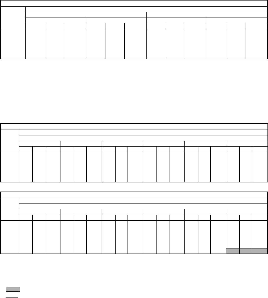
AIR DELIVERY — 558D036-150 VERTICAL DISCHARGE UNITS
558D036 (3 TON)
Airflow
(Cfm)
Standard Direct-Drive Motor
Low Speed High Speed
208 v 230, 460, 575 v 208 v 230, 460, 575 v
ESP Bhp Watts ESP Bhp Watts ESP Bhp Watts ESP Bhp Watts
900 0.67 0.21 253 0.68 0.23 277 0.69 0.26 307 0.69 0.31 363
1000 0.60 0.23 270 0.61 0.25 292 0.61 0.27 321 0.63 0.32 374
1100 0.55 0.24 287 0.56 0.26 307 0.57 0.28 335 0.58 0.33 385
1200 0.51 0.26 304 0.51 0.27 323 0.52 0.29 349 0.53 0.34 397
1300 0.45 0.27 321 0.46 0.29 338 0.46 0.31 364 0.47 0.34 408
1400 0.38 0.29 338 0.41 0.30 354 0.43 0.32 378 — — —
1500 0.34 0.30 355 0.36 0.31 369 0.38 0.33 392 — — —
LEGEND
Bhp — Brake Horsepower Input to Fan
ESP — External Static Pressure (in. wg)
FIOP — Factory-Installed Option
Watts — Input Watts to Motor
NOTES:
1. Values include losses for filters, unit casing, and wet coils. See
page 47 for accessory/FIOP static pressure information.
2. Extensive motor and electrical testing on these units ensures that the
full range of the motor can be utilized with confidence. Using your
fan motors up to the wattage ratings shown will not result in nui-
sance tripping or premature motor failure. Unit warranty will not be
affected. For additional information on motor performance, refer to
Evaporator-Fan Motor Performance table on page 62.
3. Use of a field-supplied motor may affect wire sizing. Contact your lo-
cal representative for details.
4. Minimum allowable cfm is 300 cfm/ton.
558D036 (3 TON)
Airflow
(Cfm)
Alternate Belt-Drive Motor
External Static Pressure (in. wg)
0.1 0.2 0.3 0.4 0.5 0.6
Rpm Bhp Watts Rpm Bhp Watts Rpm Bhp Watts Rpm Bhp Watts Rpm Bhp Watts Rpm Bhp Watts
900 581 0.12 119 673 0.18 179 736 0.22 219 805 0.25 249 865 0.29 288 911 0.34 338
1000 644 0.19 189 709 0.22 219 782 0.28 279 835 0.30 298 900 0.35 348 937 0.38 378
1100 687 0.22 219 746 0.26 259 806 0.30 298 867 0.35 348 929 0.40 398 964 0.40 398
1200 733 0.26 259 785 0.32 318 843 0.35 348 903 0.41 408 960 0.47 467 994 0.50 497
1300 754 0.29 288 826 0.38 378 891 0.43 428 942 0.48 477 991 0.53 527 1047 0.60 597
1400 810 0.35 348 868 0.45 448 937 0.51 507 984 0.57 567 1032 0.62 617 1067 0.67 666
1500 841 0.42 418 911 0.53 527 985 0.61 607 1029 0.66 656 1073 0.72 716 1109 0.77 766
558D036 (3 TON) (cont)
Airflow
(Cfm)
Alternate Belt-Drive Motor
External Static Pressure (in. wg)
0.7 0.8 0.9 1.0 1.1 1.2
Rpm Bhp Watts Rpm Bhp Watts Rpm Bhp Watts Rpm Bhp Watts Rpm Bhp Watts Rpm Bhp Watts
900 957 0.39 388 988 0.43 428 1039 0.45 448 1061 0.47 487 1083 0.53 527 1105 0.57 567
1000 992 0.44 438 1039 0.49 487 1061 0.51 507 1086 0.55 547 1111 0.59 587 1136 0.63 627
1100 1013 0.49 487 1068 0.55 547 1090 0.58 577 1109 0.61 607 1127 0.64 637 1145 0.67 666
1200 1045 0.56 557 1090 0.64 637 1109 0.64 647 1156 0.68 676 1203 0.71 706 1250 0.74 736
1300 1075 0.64 637 1122 0.70 696 1152 0.72 716 1190 0.76 756 1228 0.80 796 1266 0.84 836
1400 1110 0.73 726 1160 0.84 766 1181 0.81 806 1237 0.85 845 1293 0.89 885 1349 0.93 925
1500 1150 0.82 816 1190 1.00 855 1225 0.90 895 1271 0.95 945 1317 1.00 995 1363 1.05 1044
LEGEND
Bhp — Brake Horsepower Input to Fan
FIOP — Factory-Installed Option
Watts — Input Watts to Motor
NOTES:
1. Boldface indicates a field-supplied drive is required. (See Note 7.)
2. indicates field-supplied motor and drive are required.
3. indicates maximum usable bhp/watts.
4. Maximum usable watts input is 1000 and maximum continuous bhp
is 1.00. Extensive motor and electrical testing on these units ensures
that the full range of the motor can be utilized with confidence. Using
your fan motors up to the wattage ratings shown will not result in nui-
sance tripping or premature motor failure. Unit warranty will not be
affected. For additional information on motor performance, refer to
Evaporator-Fan Motor Performance table on page 62.
5. Values include losses for filters, unit casing, and wet coils. See
page 47 for accessory/FIOP static pressure information.
6. Use of a field-supplied motor may affect wire sizing. Contact your lo-
cal representative for details.
7. Motor drive range: 760 to 1000 rpm. All other rpms require field-
supplied drive.
8. Interpolation is permissible. Do not extrapolate.
9. Minimum allowable cfm is 300 cfm/ton.
26
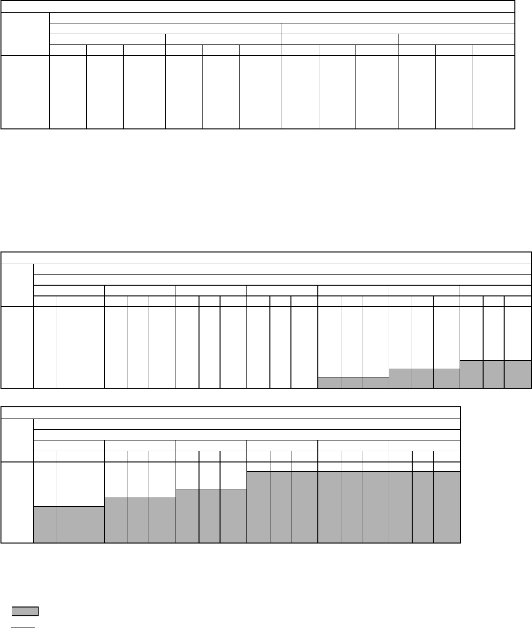
AIR DELIVERY — 558D036-150 VERTICAL DISCHARGE UNITS (cont)
558D048 (4 TON)
Airflow
(Cfm)
Standard Direct-Drive Motor
Low Speed High Speed
208 v 230, 460, 575 v 208 v 230, 460, 575 v
ESP Bhp Watts ESP Bhp Watts ESP Bhp Watts ESP Bhp Watts
1200 0.93 0.41 458 0.94 0.45 506 0.94 0.51 572 0.99 0.56 632
1300 0.86 0.42 471 0.87 0.46 521 0.87 0.52 589 0.92 0.58 651
1400 0.78 0.45 503 0.79 0.49 556 0.79 0.54 616 0.87 0.60 681
1500 0.70 0.47 536 0.73 0.52 593 0.73 0.56 631 0.80 0.62 698
1600 0.61 0.49 557 0.64 0.54 616 0.66 0.58 654 0.76 0.64 723
1700 0.51 0.52 584 0.54 0.57 646 0.58 0.60 678 0.68 0.66 750
1800 0.40 0.54 610 0.44 0.60 674 0.51 0.62 698 0.63 0.68 772
1900 0.29 0.56 629 0.37 0.62 696 0.46 0.64 720 0.56 0.70 796
2000 0.25 0.58 651 0.30 0.64 720 0.39 0.66 744 0.50 0.73 823
LEGEND
Bhp — Brake Horsepower Input to Fan
ESP — External Static Pressure (in. wg)
FIOP — Factory-Installed Option
Watts — Input Watts to Motor
NOTES:
1. Values include losses for filters, unit casing, and wet coils. See
page 47 for accessory/FIOP static pressure information.
2. Extensive motor and electrical testing on these units ensures that the
full range of the motor can be utilized with confidence. Using
your fan motors up to the wattage ratings shown will not result in nui-
sance tripping or premature motor failure. Unit warranty will not be
affected. For additional information on motor performance, refer to
Evaporator-Fan Motor Performance table on page 62.
3. Use of a field-supplied motor may affect wire sizing. Contact your lo-
cal representative for details.
4. Minimum allowable cfm is 300 cfm/ton.
558D048 (4 TON)
Airflow
(Cfm)
Alternate Belt-Drive Motor
External Static Pressure (in. wg)
0.1 0.2 0.3 0.4 0.6 0.7 0.8
Rpm Bhp Watts Rpm Bhp Watts Rpm Bhp Watts Rpm Bhp Watts Rpm Bhp Watts Rpm Bhp Watts Rpm Bhp Watts
1200 542 0.16 168 616 0.21 221 678 0.27 278 739 0.32 336 842 0.44 462 886 0.50 525 929 0.56 588
1300 576 0.20 210 644 0.25 263 704 0.31 326 764 0.37 389 867 0.50 525 910 0.56 588 952 0.62 651
1400 610 0.24 252 673 0.30 315 732 0.36 378 791 0.42 441 889 0.55 578 933 0.62 651 976 0.69 725
1500 646 0.28 294 704 0.35 368 761 0.42 436 818 0.48 504 912 0.61 641 957 0.69 720 1001 0.76 777
1600 681 0.33 347 735 0.40 420 790 0.47 494 845 0.54 567 920 0.68 695 931 0.76 772 1023 0.83 848
1700 718 0.39 410 768 0.46 483 836 0.54 562 873 0.61 641 965 0.76 777 1005 0.84 853 1045 0.91 930
1800 754 0.45 473 801 0.53 557 851 0.61 641 900 0.69 725 992 0.84 858 1032 0.92 940 1071 1.00 1022
1900 791 0.52 546 836 0.60 630 832 0.69 720 828 0.77 809 1019 0.93 950 1058 1.02 1037 1097 1.10 1124
2000 828 0.60 630 870 0.68 714 864 0.77 809 858 0.86 904 1046 1.03 1053 1085 1.12 1139 1124 1.21 1237
558D048 (4 TON) (cont)
Airflow
(Cfm)
Alternate Belt-Drive Motor
External Static Pressure (in. wg)
1.0 1.1 1.2 1.4 1.6 1.8
Rpm Bhp Watts Rpm Bhp Watts Rpm Bhp Watts Rpm Bhp Watts Rpm Bhp Watts Rpm Bhp Watts
1200 1008 0.67 704 1052 0.73 762 1096 0.78 820 1134 0.89 835 1203 1.00 885 —— —
1300 1029 0.75 788 1065 0.81 846 1101 0.86 904 1174 1.01 1040 1229 1.15 1100 1277 1.27 1029
1400 1052 0.83 826 1087 0.90 890 1121 0.96 918 1183 1.09 1042 1255 1.22 1167 1305 1.38 1190
1500 1076 0.91 905 1111 0.99 980 1145 1.06 1014 1208 1.20 1138 1274 1.33 1272 1337 1.47 1350
1600 1100 1.00 995 1134 1.08 1069 1168 1.15 1100 1232 1.31 1253 1291 1.46 1396 1350 1.60 1558
1700 1124 1.09 1084 1158 1.17 1164 1192 1.25 1196 1255 1.42 1358 1314 1.58 1511 1370 1.77 1738
1800 1147 1.18 1174 1182 1.27 1263 1217 1.36 1301 1279 1.54 1473 1381 1.71 1635 1393 1.89 1907
1900 1169 1.27 1263 1205 1.37 1363 1240 1.47 1406 1303 1.66 1588 1408 1.85 1769 1417 2.03 2068
2000 1194 1.38 1373 1228 1.48 1472 1262 1.58 1511 1327 1.78 1702 1436 1.98 1894 1440 2.18 2229
LEGEND
Bhp — Brake Horsepower Input to Fan
FIOP — Factory-Installed Option
Watts — Input Watts to Motor
NOTES:
1. Boldface indicates a field-supplied drive is required. (See Note 7.)
2. indicates field-supplied motor and drive are required.
3. indicates maximum usable bhp/watts.
4. Maximum usable watts input is 1000 and maximum continuous bhp
is 1.00. Extensive motor and electrical testing on these units ensures
that the full range of the motor can be utilized with confidence. Using
your fan motors up to the wattage ratings shown will not result in nui-
sance tripping or premature motor failure. Unit warranty will not be
affected. For additional information on motor performance, refer to
Evaporator-Fan Motor Performance table on page 62.
5. Values include losses for filters, unit casing, and wet coils. See
page 47 for accessory/FIOP static pressure information.
6. Use of a field-supplied motor may affect wire sizing. Contact your lo-
cal representative for details.
7. Motor drive range: 835 to 1185 rpm. All other rpms require field-
supplied drive.
8. Interpolation is permissible. Do not extrapolate.
9. Minimum allowable cfm is 300 cfm/ton.
27
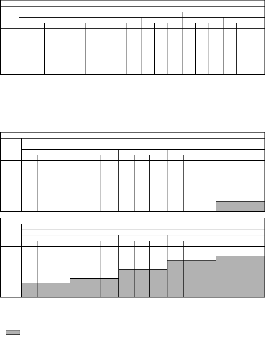
AIR DELIVERY — 558D036-150 VERTICAL DISCHARGE UNITS (cont)
558D060 (5 TON)
Airflow
(Cfm)
Standard Direct-Drive Motor
Low Speed Medium Speed High Speed
208 v 230, 460, 575 v 208 v 230, 460, 575 v 208 v 230, 460, 575 v
ESP Bhp Watts ESP Bhp Watts ESP Bhp Watts ESP Bhp Watts ESP Bhp Watts ESP Bhp Watts
1500 0.88 0.67 750 1.20 0.71 791 1.19 0.70 782 1.36 0.76 845 1.38 0.79 875 1.44 0.85 949
1600 0.68 0.70 780 1.04 0.74 824 1.04 0.74 821 1.22 0.79 883 1.25 0.82 913 1.33 0.89 988
1700 0.51 0.73 810 0.89 0.77 857 0.89 0.77 861 1.09 0.83 921 1.13 0.85 950 1.22 0.92 1027
1800 0.35 0.75 839 0.73 0.80 891 0.74 0.81 900 0.96 0.86 959 1.00 0.89 988 1.11 0.96 1066
1900 0.26 0.78 873 0.58 0.83 924 0.59 0.84 940 0.86 0.90 997 0.88 0.92 1025 1.00 0.99 1105
2000 0.18 0.81 905 0.42 0.86 957 0.44 0.88 979 0.73 0.93 1035 0.78 0.95 1063 0.92 1.03 1144
2100 0.08 0.84 940 0.27 0.89 990 0.29 0.91 1018 0.59 0.96 1073 0.63 0.99 1101 0.81 1.06 1183
2200 — — — 0.19 0.92 1023 0.19 0.93 1035 0.46 1.00 1111 0.49 1.02 1138 0.69 1.10 1222
2300 — — — 0.11 0.95 1056 0.11 0.97 1076 0.34 1.03 1149 0.41 1.06 1176 0.59 1.13 1261
2400 — — — 0.03 0.98 1096 0.04 1.00 1113 0.19 1.07 1187 0.22 1.09 1213 0.43 1.17 1300
2500 — — — — — — — — — 0.09 1.10 1225 0.12 1.12 1251 0.34 1.20 1340
LEGEND
Bhp — Brake Horsepower Input to Fan
ESP — External Static Pressure (in. wg)
FIOP — Factory-Installed Option
Watts — Input Watts to Motor
NOTES:
1. Values include losses for filters, unit casing, and wet coils. See
page 47 for accessory/FIOP static pressure information.
2. Extensive motor and electrical testing on these units ensures that the
full range of the motor can be utilized with confidence. Using
your fan motors up to the wattage ratings shown will not result in nui-
sance tripping or premature motor failure. Unit warranty will not be
affected. For additional information on motor performance, refer to
Evaporator-Fan Motor Performance table on page 62.
3. Use of a field-supplied motor may affect wire sizing. Contact your lo-
cal representative for details.
4. Minimum allowable cfm is 300 cfm/ton.
558D060 (5 TON)
Airflow
(Cfm)
Alternate Belt-Drive Motor
External Static Pressure (in. wg)
0.1 0.2 0.4 0.6 0.8
Rpm Bhp Watts Rpm Bhp Watts Rpm Bhp Watts Rpm Bhp Watts Rpm Bhp Watts
1500 730 0.34 347 789 0.40 409 896 0.53 542 990 0.67 685 1072 0.83 848
1600 770 0.40 409 826 0.46 470 931 0.61 623 1020 0.75 766 1101 0.91 930
1700 811 0.47 480 865 0.54 552 966 0.69 705 1051 0.84 858 1133 1.01 1032
1800 852 0.55 562 905 0.62 634 1002 0.78 797 1084 0.93 950 1163 1.10 1124
1900 894 0.54 552 945 0.72 736 1037 0.88 899 1119 1.04 1063 1194 1.21 1237
2000 936 0.74 756 984 0.82 838 1072 0.98 1001 1154 1.16 1185 1226 1.33 1359
2100 978 0.85 869 1024 0.93 950 1108 1.10 1124 1192 1.29 1318 1259 1.47 1502
2200 1021 0.97 991 1064 1.05 1073 1145 1.22 1247 1225 1.43 1461 1294 1.62 1656
2300 1064 1.10 1124 1104 1.18 1206 1183 1.36 1390 1260 1.57 1604 1330 1.78 1819
2400 1107 1.24 1267 1145 1.32 1349 1222 1.45 1482 1296 1.73 1768 1365 1.94 1983
2500 1150 1.39 1420 1186 1.48 1512 1262 1.68 1717 1331 1.80 1921 1400 2.12 2166
558D060 (5 TON) (cont)
Airflow
(Cfm)
Alternate Belt-Drive Motor
External Static Pressure (in. wg)
1.0 1.2 1.4 1.6 1.8
Rpm Bhp Watts Rpm Bhp Watts Rpm Bhp Watts Rpm Bhp Watts Rpm Bhp Watts
1500 1153 1.00 1022 1221 1.17 1196 1256 1.30 1328 1280 1.32 1349 1320 1.22 1400
1600 1178 1.09 1114 1252 1.27 1298 1311 1.45 1482 1340 1.58 1615 1380 1.61 1645
1700 1205 1.18 1206 1278 1.37 1400 1345 1.57 1604 1397 1.76 1799 1424 1.89 1931
1800 1235 1.29 1318 1303 1.48 1512 1371 1.69 1727 1433 1.90 1942 1480 2.09 2136
1900 1266 1.40 1431 1330 1.59 1625 1396 1.80 1850 1460 2.03 2074 1517 2.25 2299
2000 1297 1.53 1564 1362 1.73 1768 1422 1.94 1983 1485 2.16 2207 1544 2.40 2453
2100 1327 1.66 1696 1393 1.80 1911 1452 2.08 2126 1510 2.31 2361 1569 2.55 2606
2200 1359 1.80 1850 1423 2.02 2064 1483 2.24 2289 1538 2.46 2514 1595 2.71 2769
2300 1392 1.97 2013 1454 2.18 2228 1515 2.41 2463 1569 2.64 2698 1622 2.88 2943
2400 1426 2.15 2197 1485 2.36 2412 1544 2.59 2647 1601 2.84 2902 1652 3.07 3137
2500 1461 2.34 2391 1518 2.55 2606 1575 2.78 2841 1631 3.03 3096 1684 3.28 3352
LEGEND
Bhp — Brake Horsepower Input to Fan
FIOP — Factory-Installed Option
Watts — Input Watts to Motor
NOTES:
1. Boldface indicates a field-supplied drive is required. (See Note 7.)
2. indicates field-supplied motor and drive are required.
3. indicates maximum usable bhp/watts.
4. Maximum usable watts input is 1921 and maximum continuous bhp
is 1.80. Extensive motor and electrical testing on these units ensures
that the full range of the motor can be utilized with confidence. Using
your fan motors up to the wattage ratings shown will not result in nui-
sance tripping or premature motor failure. Unit warranty will not be
affected. For additional information on motor performance, refer to
Evaporator-Fan Motor Performance table on page 62.
5. Values include losses for filters, unit casing, and wet coils. See
page 47 for accessory/FIOP static pressure information.
6. Use of a field-supplied motor may affect wire sizing. Contact your lo-
cal representative for details.
7. Motor drive range: 900 to 1300 rpm. All other rpms require field-
supplied drive.
8. Interpolation is permissible. Do not extrapolate.
9. Minimum allowable cfm is 300 cfm/ton.
28
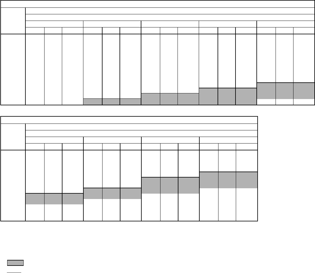
AIR DELIVERY — 558D036-150 VERTICAL DISCHARGE UNITS (cont)
558D072 (6 TON)
Airflow
(Cfm)
Standard Belt-Drive Motor
External Static Pressure (in. wg)
0.1 0.2 0.4 0.6 0.8
Rpm Bhp Watts Rpm Bhp Watts Rpm Bhp Watts Rpm Bhp Watts Rpm Bhp Watts
1800 852 0.55 562 905 0.62 615 1002 0.78 739 1084 0.93 859 1163 1.10 998
1900 894 0.64 630 945 0.72 692 1037 0.88 818 1119 1.04 948 1194 1.21 1089
2000 936 0.74 708 984 0.82 771 1072 0.98 899 1154 1.16 1047 1226 1.33 1190
2100 978 0.85 795 1024 0.93 859 1108 1.10 998 1190 1.29 1156 1259 1.47 1310
2200 1021 0.97 891 1064 1.05 956 1145 1.22 1097 1225 1.43 1275 1294 1.62 1439
2300 1064 1.10 998 1104 1.18 1064 1183 1.36 1216 1260 1.57 1396 1330 1.78 1578
2400 1107 1.24 1114 1145 1.32 1182 1222 1.52 1353 1296 1.73 1534 1365 1.94 1718
2500 1150 1.39 1241 1186 1.48 1318 1262 1.68 1491 1331 1.89 1674 1400 2.12 1875
2600 1193 1.56 1387 1228 1.65 1465 1301 1.86 1648 1367 2.07 1831 1435 2.31 2041
2700 1237 1.74 1543 1269 1.83 1621 1341 2.05 1814 1404 2.26 1997 1471 2.51 2214
2800 1280 1.94 1718 1311 2.03 1796 1381 2.25 1989 1442 2.47 2180 1506 2.72 2394
2900 1324 2.15 1901 1354 2.24 1980 1420 2.47 2180 1481 2.69 2369 1542 2.94 2579
3000 1368 2.37 2093 1396 2.46 2171 1460 2.69 2369 1521 2.93 2571 — — —
558D072 (6 TON) (cont)
Airflow
(Cfm)
Standard Belt-Drive Motor
External Static Pressure (in. wg)
1.0 1.2 1.4 1.6
Rpm Bhp Watts Rpm Bhp Watts Rpm Bhp Watts Rpm Bhp Watts
1800 1235 1.29 1156 1303 1.48 1318 1371 1.69 1499 1433 1.90 1638
1900 1266 1.40 1250 1330 1.59 1413 1396 1.81 1604 1460 2.03 1796
2000 1297 1.53 1361 1362 1.73 1534 1422 1.94 1718 1485 2.16 1910
2100 1327 1.66 1473 1393 1.87 1656 1452 2.08 1840 1510 2.31 2041
2200 1359 1.81 1604 1423 2.02 1779 1483 2.24 1980 1538 2.46 2171
2300 1392 1.97 1744 1454 2.18 1927 1515 2.41 2128 1569 2.64 2326
2400 1426 2.15 1901 1485 2.36 2084 1544 2.59 2283 1601 2.84 2459
2500 1461 2.34 2067 1518 2.55 2249 1575 2.78 2445 — — —
2600 1497 2.54 2240 1552 2.76 2428 — — — — — —
2700 1532 2.75 2420 — — — — — — — — —
2800 —— — —— — —— — —— —
2900 —— — —— — —— — —— —
3000 —— — —— — —— — —— —
LEGEND
Bhp — Brake Horsepower Input to Fan
FIOP — Factory-Installed Option
Watts — Input Watts to Motor
NOTES:
1. Boldface indicates a field-supplied drive is required. (See Note 7.)
2. indicates field-supplied motor and drive are required.
3. indicates maximum usable bhp/watts.
4. Maximum usable watts input is 2120 and maximum continuous bhp
is 2.40. Extensive motor and electrical testing on these units ensures
that the full range of the motor can be utilized with confidence. Using
your fan motors up to the wattage ratings shown will not result in nui-
sance tripping or premature motor failure. Unit warranty will not be
affected. For additional information on motor performance, refer to
Evaporator-Fan Motor Performance table on page 62.
5. Values include losses for filters, unit casing, and wet coils. See
page 47 for accessory/FIOP static pressure information.
6. Use of a field-supplied motor may affect wire sizing. Contact your lo-
cal representative for details.
7. Motor drive range: 1070 to 1460 rpm. All other rpms require field-
supplied drive.
8. Interpolation is permissible. Do not extrapolate.
9. Minimum allowable cfm is 300 cfm/ton.
29
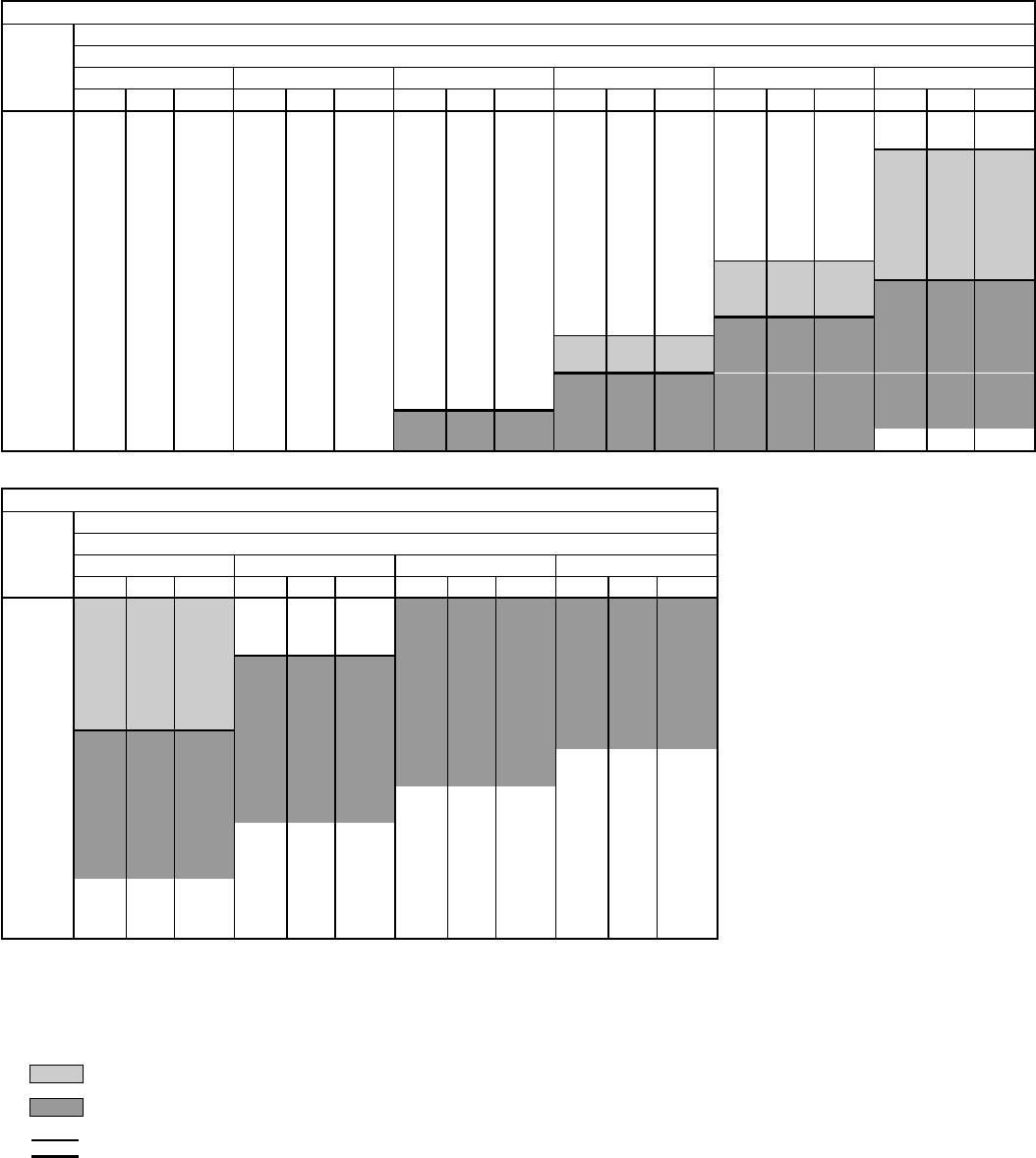
AIR DELIVERY — 558D036-150 VERTICAL DISCHARGE UNITS (cont)
558D090 (7
1
⁄
2
TON)
Airflow
(Cfm)
Standard Belt-Drive Motor
External Static Pressure (in. wg)
0.2 0.4 0.6 0.8 1.0 1.2
Rpm Bhp Watts Rpm Bhp Watts Rpm Bhp Watts Rpm Bhp Watts Rpm Bhp Watts Rpm Bhp Watts
2250 511 0.52 539 592 0.74 708 659 0.95 875 722 1.19 1072 778 1.43 1275 829 1.68 1491
2300 518 0.55 562 599 0.77 731 665 0.98 899 727 1.22 1097 783 1.47 1310 834 1.72 1526
2400 534 0.61 607 613 0.84 787 677 1.06 965 738 1.30 1165 794 1.55 1378 844 1.81 1604
2500 549 0.67 653 627 0.90 835 690 1.14 1031 750 1.38 1233 805 1.64 1456 855 1.91 1691
2550 557 0.71 684 633 0.94 867 697 1.18 1064 756 1.42 1267 811 1.69 1499 861 1.96 1735
2600 565 0.74 708 639 0.97 891 703 1.22 1097 761 1.46 1301 816 1.74 1543 866 2.01 1779
2700 581 0.81 763 652 1.04 948 717 1.31 1173 773 1.55 1378 827 1.83 1621 878 2.12 1875
2800 597 0.89 827 665 1.12 1014 733 1.40 1250 786 1.66 1473 839 1.93 1709 889 2.23 1971
2900 613 0.97 891 679 1.20 1081 745 1.50 1335 799 1.76 1560 850 2.04 1805 900 2.34 2067
3000 629 1.06 965 694 1.29 1156 759 1.59 1413 812 1.88 1665 862 2.15 1901 911 2.46 2171
3100 646 1.15 1039 709 1.39 1241 772 1.70 1508 825 1.99 1761 875 2.28 2015 923 2.58 2275
3200 662 1.25 1123 724 1.50 1335 785 1.80 1595 840 2.11 1866 887 2.41 2128 934 2.71 2386
3300 679 1.35 1207 740 1.61 1430 798 1.91 1691 854 2.24 1980 900 2.54 2240 946 2.85 2504
3400 696 1.46 1301 756 1.73 1534 811 2.02 1788 868 2.37 2093 914 2.69 2369 959 3.00 2629
3500 712 1.57 1396 771 1.85 1639 824 2.14 1892 881 2.50 2206 928 2.84 2495 971 3.16 2759
3600 729 1.69 1499 787 1.98 1753 839 2.21 2006 894 2.64 2326 942 2.99 2620 984 3.22 2886
3700 746 1.85 1613 803 2.12 1875 854 2.42 2136 907 2.78 2445 956 3.15 2751 997 3.49 3017
3750 755 1.89 1674 811 2.20 1945 862 2.49 2197 914 2.85 2504 963 3.23 2815 — — —
558D090 (7
1
⁄
2
TON) (cont)
Airflow
(Cfm)
Standard Belt-Drive Motor
External Static Pressure (in. wg)
1.4 1.6 1.8 2.0
Rpm Bhp Watts Rpm Bhp Watts Rpm Bhp Watts Rpm Bhp Watts
2250 884 1.97 1744 937 2.33 2058 947 2.66 2343 1022 3.10 2710
2300 885 2.00 1770 939 2.36 2084 979 2.69 2369 1025 3.12 2727
2400 892 2.08 1840 944 2.40 2119 987 2.76 2428 1039 3.20 2791
2500 902 2.18 1927 949 2.48 2188 1002 2.84 2495 1041 3.25 2831
2550 908 2.24 1980 953 2.53 2232 1003 2.87 2521 1045 3.28 2854
2600 913 2.29 2023 957 2.58 2275 1004 2.91 2554 1050 3.31 2878
2700 924 2.40 2120 967 2.70 2377 1010 3.01 2637 1056 3.37 2925
2800 935 2.52 2223 978 2.62 2479 1019 3.13 2735 1061 3.47 3002
2900 946 2.65 2335 989 2.96 2595 1030 3.27 2847 — — —
3000 957 2.78 2445 1000 3.09 2702 1040 3.41 2956 — — —
3100 968 2.91 2554 1011 3.24 2832 — — — — — —
3200 980 3.04 2661 1022 3.38 2933 — — — — — —
3300 991 3.18 2775 — — — — — — — — —
3400 1003 3.32 2886 — — — — — — — — —
3500 1014 3.48 3009 — — — — — — — — —
3600 —— — —— — —— — —— —
3700 —— — —— — —— — —— —
3750 —— — —— — —— — —— —
LEGEND
Bhp — Brake Horsepower Input to Fan
FIOP — Factory-Installed Option
Watts — Input Watts to Motor
NOTES:
1. Boldface indicates a field-supplied drive is required. (See Note 9.)
2. indicates alternate drive is required.
3. indicates field-supplied motor and drive are required.
4. indicates maximum usable bhp/watts of standard drive.
5. indicates maximum usable bhp/watts of alternate drive.
6. Maximum usable watts input is 2120 and maximum continuous bhp
is 2.40. Extensive motor and electrical testing on these units
ensures that the full range of the motor can be utilized with confi-
dence. Using your fan motors up to the wattage ratings shown will
not result in nuisance tripping or premature motor failure. Unit war-
ranty will not be affected. For additional information on motor per-
formance refer to Evaporator-Fan Motor Performance table on
page 62.
7. Values include losses for filters, unit casing, and wet coils. See
page 47 for accessory/FIOP static pressure information.
8. Use of a field-supplied motor may affect wire sizing. Contact your
local representative for details.
9. Standard drive range: 590 to 840 rpm. Alternate drive range: 685 to
935 rpm. All other rpms require field-supplied drive.
10. Interpolation is permissible. Do not extrapolate.
11. Minimum allowable cfm is 300 cfm/ton.
30
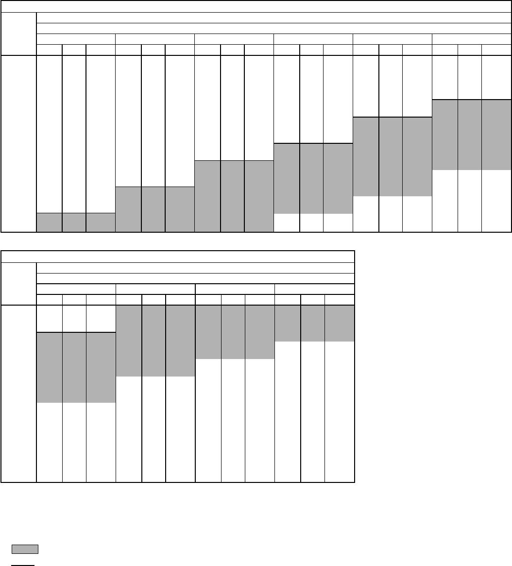
AIR DELIVERY — 558D036-150 VERTICAL DISCHARGE UNITS (cont)
558D102 (8
1
⁄
2
TON)
Airflow
(Cfm)
Standard Belt-Drive Motor
External Static Pressure (in. wg)
0.2 0.4 0.6 0.8 1.0 1.2
Rpm Bhp Watts Rpm Bhp Watts Rpm Bhp Watts Rpm Bhp Watts Rpm Bhp Watts Rpm Bhp Watts
2550 557 0.71 684 633 0.94 867 697 1.18 1064 756 1.42 1267 811 1.69 1499 861 1.96 1735
2600 565 0.74 708 639 0.97 891 703 1.22 1097 761 1.46 1301 816 1.74 1543 866 2.01 1779
2700 581 0.81 763 652 1.04 948 717 1.31 1173 773 1.55 1378 827 1.83 1621 878 2.12 1875
2800 597 0.89 827 665 1.12 1014 733 1.40 1250 786 1.66 1473 839 1.93 1709 889 2.23 1971
2900 613 0.97 891 679 1.20 1081 745 1.50 1335 799 1.76 1560 850 2.04 1805 900 2.34 2067
3000 629 1.06 965 694 1.29 1156 759 1.59 1413 812 1.88 1665 862 2.15 1901 911 2.46 2171
3100 646 1.15 1039 709 1.39 1241 772 1.70 1508 825 1.99 1761 875 2.28 2015 923 2.58 2275
3200 662 1.25 1123 724 1.50 1335 785 1.80 1595 840 2.11 1866 887 2.41 2128 934 2.71 2386
3300 679 1.35 1207 740 1.61 1430 798 1.91 1691 854 2.24 1980 900 2.54 2240 946 2.85 2504
3400 696 1.46 1301 756 1.73 1534 811 2.02 1788 868 2.37 2093 914 2.69 2369 959 3.00 2629
3500 712 1.57 1396 771 1.85 1639 824 2.14 1892 881 2.50 2206 928 2.84 2495 971 3.16 2759
3600 729 1.69 1499 787 1.98 1753 839 2.27 2006 894 2.64 2326 942 2.99 2620 984 3.32 2886
3700 746 1.82 1613 803 2.12 1875 854 2.42 2136 907 2.78 2445 956 3.15 2751 997 3.49 3017
3750 755 1.89 1674 811 2.20 1945 862 2.49 2197 914 2.85 2504 963 3.23 2815 — — —
3800 763 1.95 1726 819 2.27 2006 869 2.56 2257 920 2.92 2562 970 3.31 2878 — — —
3900 780 2.09 1849 835 2.42 2136 884 2.72 2394 933 3.07 2686 983 3.48 3009 — — —
4000 796 2.23 1971 851 2.56 2257 900 2.89 2537 946 3.23 2815 — — — — — —
4100 813 2.39 2110 867 2.74 2411 915 3.06 2678 960 3.40 2948 — — — — — —
4200 830 2.55 2249 883 2.91 2554 931 3.24 2823 — — — — — — — — —
4250 839 2.63 2317 892 3.00 2629 939 3.34 2902 — — — — — — — — —
558D102 (8
1
⁄
2
TON) (cont)
Airflow
(Cfm)
Standard Belt-Drive Motor
External Static Pressure (in. wg)
1.4 1.6 1.8 2.0
Rpm Bhp Watts Rpm Bhp Watts Rpm Bhp Watts Rpm Bhp Watts
2550 908 2.24 1980 953 2.53 2232 1003 2.87 2521 1045 3.28 2854
2600 913 2.29 2023 957 2.58 2275 1004 2.91 2554 1050 3.31 2878
2700 924 2.40 2120 967 2.70 2377 1010 3.01 2637 1056 3.37 2925
2800 935 2.52 2223 978 2.62 2479 1019 3.13 2735 1061 3.41 3002
2900 946 2.65 2335 989 2.96 2595 1030 3.27 2847 — — —
3000 957 2.78 2445 1000 3.09 2702 1040 3.41 2956 — — —
3100 968 2.91 2554 1011 3.24 2832 — — — — — —
3200 980 3.04 2661 1022 3.38 2933 — — — — — —
3300 991 3.18 2775 — — — — — — — — —
3400 1003 3.52 2886 — — — — — — — — —
3500 1014 3.48 3009 — — — — — — — — —
3600 —— — —— — —— — —— —
3700 —— — —— — —— — —— —
3750 —— — —— — —— — —— —
3800 —— — —— — —— — —— —
3900 —— — —— — —— — —— —
4000 —— — —— — —— — —— —
4100 —— — —— — —— — —— —
4200 —— — —— — —— — —— —
4250 —— — —— — —— — —— —
LEGEND
Bhp — Brake Horsepower Input to Fan
FIOP — Factory-Installed Option
Watts — Input Watts to Motor
NOTES:
1. Boldface indicates a field-supplied drive is required. (See Note 7.)
2. indicates field-supplied motor and drive are required.
3. indicates maximum usable bhp/watts.
4. Maximum usable watts input is 2120 and maximum continuous bhp
is 2.40. Extensive motor and electrical testing on these units ensures
that the full range of the motor can be utilized with confidence. Using
your fan motors up to the wattage ratings shown will not result in nui-
sance tripping or premature motor failure. Unit warranty will not be
affected. For additional information on motor performance refer to
Evaporator-Fan Motor Performance table on page 62.
5. Values include losses for filters, unit casing, and wet coils. See
page 47 for accessory/FIOP static pressure information.
6. Use of a field-supplied motor may affect wire sizing. Contact your lo-
cal representative for details.
7. Motor drive range: 685 to 935 rpm. All other rpms require field-
supplied drive.
8. Interpolation is permissible. Do not extrapolate.
9. Minimum allowable cfm is 300 cfm/ton.
31
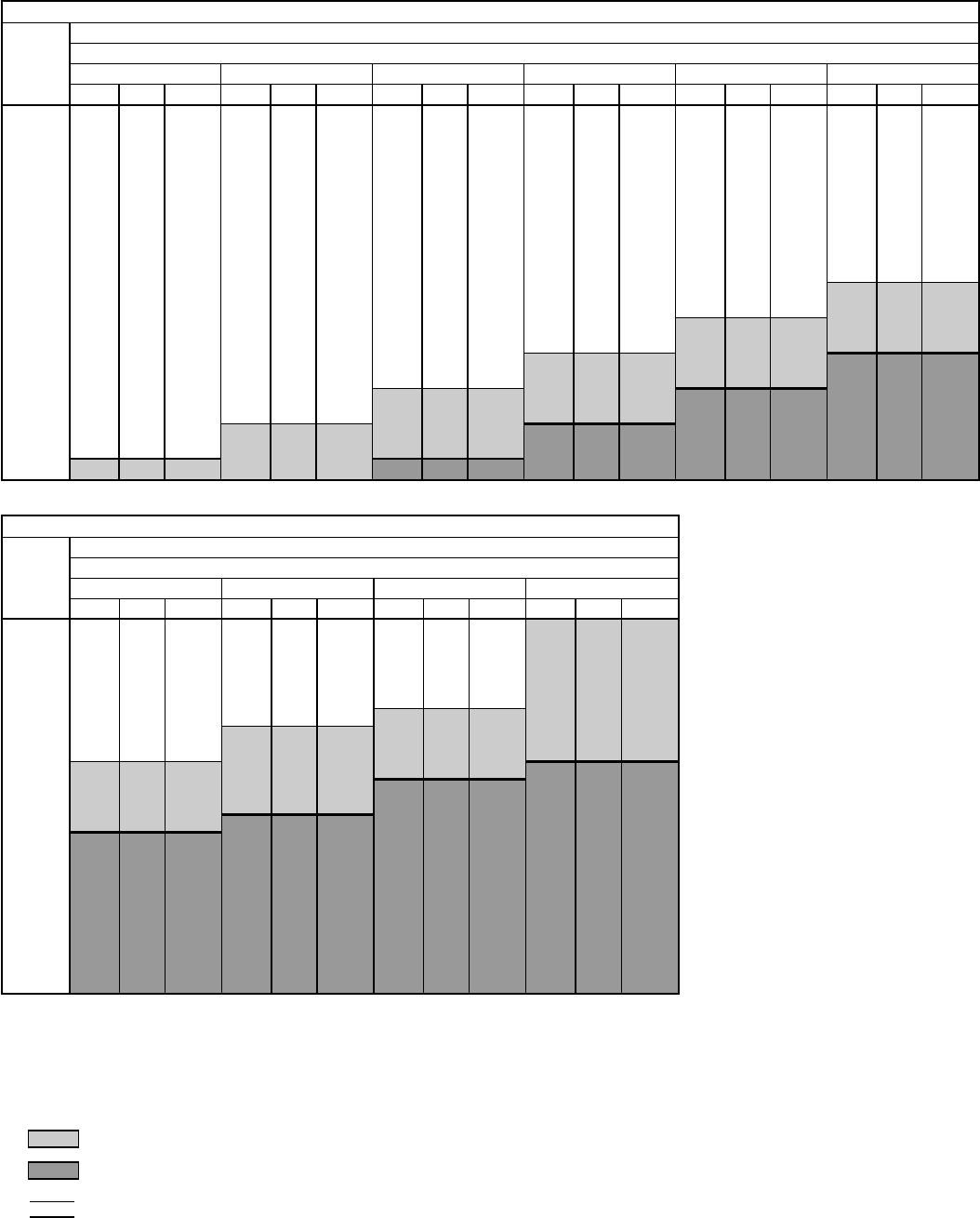
AIR DELIVERY — 558D036-150 VERTICAL DISCHARGE UNITS (cont)
558D120 (10 TON)
Airflow
(Cfm)
Standard and Alternate Belt-Drive Motors
External Static Pressure (in. wg)
0.2 0.4 0.6 0.8 1.0 1.2
Rpm Bhp Watts Rpm Bhp Watts Rpm Bhp Watts Rpm Bhp Watts Rpm Bhp Watts Rpm Bhp Watts
3000 532 0.64 630 605 0.81 763 670 0.97 891 725 1.12 1014 778 1.28 1148 825 1.43 1275
3100 544 0.70 677 616 0.86 803 680 1.03 940 735 1.20 1081 787 1.36 1216 835 1.52 1353
3200 557 0.75 716 628 0.93 859 690 1.10 998 746 1.28 1148 796 1.44 1284 844 1.61 1430
3300 570 0.81 763 639 0.99 907 700 1.18 1064 757 1.36 1216 805 1.52 1353 854 1.70 1508
3400 583 0.88 818 651 1.06 965 711 1.25 1123 767 1.44 1284 815 1.61 1430 863 1.79 1587
3500 596 0.94 867 663 1.14 1031 721 1.33 1190 777 1.52 1353 826 1.71 1517 871 1.88 1665
3600 609 1.01 924 674 1.22 1097 732 1.42 1267 787 1.61 1430 836 1.80 1595 880 1.98 1753
3700 622 1.09 989 686 1.30 1165 744 1.50 1335 797 1.70 1508 847 1.91 1691 890 2.09 1849
3800 635 1.16 1047 698 1.39 1241 755 1.59 1413 808 1.80 1595 857 2.01 1779 901 2.20 1945
3900 649 1.25 1123 713 1.48 1318 767 1.68 1491 818 1.90 1683 867 2.11 1866 912 2.32 2050
4000 662 1.33 1190 722 1.57 1396 778 1.78 1578 829 2.01 1779 878 2.22 1962 922 2.44 2203
4100 675 1.42 1267 734 1.67 1482 790 1.89 1674 839 2.12 1875 888 2.33 2058 933 2.56 2309
4200 689 1.52 1353 746 1.77 1569 801 1.99 1761 851 2.23 1971 898 2.45 2212 943 2.69 2424
4300 702 1.61 1430 759 1.88 1665 813 2.11 1866 862 2.34 2067 908 2.58 2326 953 2.81 2533
4400 715 1.72 1526 772 1.99 1761 825 2.22 1962 873 2.46 2221 919 2.71 2442 963 2.94 2651
4500 729 1.83 1621 785 2.10 1858 837 2.35 2076 885 2.59 2335 929 2.85 2569 973 3.08 2782
4600 742 1.94 1718 797 2.22 1962 848 2.48 2238 896 2.72 2451 940 2.98 2688 984 3.22 2914
4700 756 2.06 1823 810 2.34 2067 860 2.61 2353 908 2.86 2578 951 3.12 2727 994 3.38 3068
4800 770 2.18 1927 823 2.46 2221 872 2.75 2505 919 3.00 2707 963 3.27 2847 1003 3.43 3202
4900 783 2.31 2041 836 2.60 2344 884 2.89 2605 931 3.14 2838 974 3.41 2956 1013 3.59 3349
5000 797 2.44 2203 849 2.73 2460 897 3.04 2661 943 3.30 2870 984 3.44 3211 1023 3.75 3501
558D120 (10 TON) (cont)
Airflow
(Cfm)
Standard and Alternate Belt-Drive Motors
External Static Pressure (in. wg)
1.4 1.6 1.8 2.0
Rpm Bhp Watts Rpm Bhp Watts Rpm Bhp Watts Rpm Bhp Watts
3000 874 1.60 1422 926 1.82 1613 974 2.11 1920 1012 2.41 2134
3100 880 1.68 1491 933 1.87 1656 983 2.16 1963 1017 2.44 2177
3200 888 1.77 1569 934 1.94 1718 988 2.18 1980 1025 2.47 2230
3300 897 1.86 1648 940 2.03 1853 989 2.24 2031 1032 2.53 2282
3400 907 1.97 1744 947 2.14 1946 991 2.32 2099 1038 2.57 2318
3500 916 2.07 1831 956 2.25 2039 997 2.43 2195 1043 2.64 2380
3600 926 2.18 1927 966 2.41 2134 1004 2.54 2291 1045 2.74 2478
3700 934 2.28 2015 976 2.48 2238 1013 2.66 2397 1051 2.85 2569
3800 943 2.41 2160 985 2.60 2334 1023 2.79 2514 1059 2.98 2688
3900 952 2.51 2265 994 2.72 2451 1032 2.92 2633 1068 3.12 2819
4000 962 2.63 2371 1003 2.84 2560 1042 3.06 2763 1078 3.26 2952
4100 973 2.77 2496 1011 2.97 2679 1051 3.20 2895 1087 3.41 3097
4200 983 2.91 2624 1021 3.11 2810 1060 3.34 3029 1090 3.51 3276
4300 994 3.05 2754 1031 3.25 2943 1068 3.48 3166 1097 3.70 3453
4400 1004 3.19 2885 1042 3.41 3097 1080 3.63 3388 1105 3.91 3642
4500 1015 3.33 2020 1051 3.45 3218 1090 3.75 3493 1112 4.12 3843
4600 1025 3.48 3166 1060 3.61 3369 1100 3.92 3655 1119 4.35 4057
4700 1037 3.58 3335 1070 3.84 3325 1111 4.10 3822 1126 4.59 4284
4800 1048 3.75 3494 1080 3.95 3686 1121 4.28 3995 1133 4.85 4523
4900 1060 3.92 3659 1089 4.13 3854 1132 4.48 4174 1140 5.12 4775
5000 1072 4.11 3830 1099 4.32 4027 1144 4.67 4359 1147 5.40 5040
LEGEND
Bhp — Brake Horsepower Input to Fan
FIOP — Factory-Installed Option
Watts — Input Watts to Motor
NOTES:
1. Boldface indicates a field-supplied or alternate (as appropriate)
drive is required. (See Note 9.)
2. indicates alternate motor and drive are required.
3. indicates field-supplied motor and drive are required.
4. indicates maximum usable bhp/watts of standard motor.
5. indicates maximum usable bhp/watts of alternate motor.
6. Maximum usable watts input is 2120 with standard motor and 2615
with alternate motor. Maximum continuous bhp is 2.40 with
standard motor and 2.90 with alternate motor. Extensive motor and
electrical testing on these units ensures that the full range of the
motor can be utilized with confidence. Using your fan motors up to
the wattage ratings shown will not result in nuisance tripping or pre-
mature motor failure. Unit warranty will not be affected. For addi-
tional information on motor performance, refer to Evaporator-Fan
Motor Performance table on page 62.
7. Values include losses for filters, unit casing, and wet coils. See
page 47 for accessory/FIOP static pressure information.
8. Use of a field-supplied motor may affect wire sizing. Contact your
local representative for details.
9. Standard motor drive range: 685 to 935 rpm. Alternate motor drive
range: 835 to 1085 rpm. All other rpms require field-supplied drive.
10. Interpolation is permissible. Do not extrapolate.
11. Minimum allowable cfm is 300 cfm/ton.
32
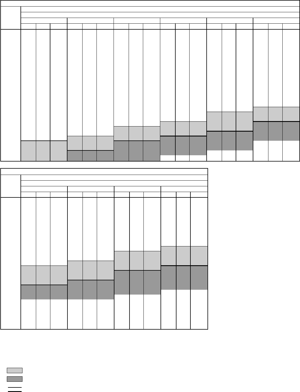
AIR DELIVERY — 558D036-150 VERTICAL DISCHARGE UNITS (cont)
558D150 (12
1
⁄
2
TON)
Airflow
(Cfm)
Standard and Alernate Belt-Drive Motors
External Static Pressure (in. wg)
0.2 0.4 0.6 0.8 1.0 1.2
Rpm Bhp Watts Rpm Bhp Watts Rpm Bhp Watts Rpm Bhp Watts Rpm Bhp Watts Rpm Bhp Watts
3750 661 1.16 1097 721 1.36 1255 774 1.55 1415 821 1.72 1556 867 1.90 1709 911 2.13 1905
3800 668 1.20 1129 727 1.40 1291 780 1.60 1456 827 1.77 1598 873 1.95 1751 916 2.18 1948
3900 683 1.28 1194 741 1.49 1365 793 1.70 1540 839 1.88 1691 884 2.05 1836 927 2.28 2035
4000 697 1.37 1267 754 1.59 1448 806 1.80 1624 851 1.99 1785 895 2.16 1931 938 2.38 2123
4100 711 1.46 1340 767 1.69 1531 819 1.90 1708 864 2.10 1879 907 2.28 2035 949 2.49 2219
4200 726 1.56 1423 780 1.80 1624 832 2.01 1802 877 2.22 1983 919 2.41 2149 960 2.60 2316
4300 741 1.66 1506 794 1.91 1717 845 2.12 1897 889 2.35 2096 931 2.54 2263 971 2.72 2433
4400 755 1.77 1598 808 2.03 1819 858 2.24 2000 902 2.48 2210 943 2.68 2387 983 2.86 2548
4500 770 1.89 1700 821 2.15 1923 871 2.37 2114 915 2.61 2325 955 2.82 2512 995 3.01 2683
4600 784 2.00 1794 835 2.27 2027 884 2.49 2219 928 2.75 2450 968 2.96 2638 1006 3.17 2828
4700 799 2.13 1905 849 2.40 2140 897 2.63 2343 941 2.88 2566 981 3.11 2773 1018 3.32 2964
4800 814 2.25 2009 863 2.53 2254 910 2.77 2468 954 3.02 2692 993 3.27 2919 1030 3.48 3111
4900 829 2.39 2131 877 2.67 2378 923 2.92 2602 967 3.17 2828 1006 3.43 3065 1043 3.65 3267
5000 843 2.52 2246 892 2.81 2503 937 3.08 2746 980 3.32 2964 1019 3.60 3221 1055 3.82 3424
5100 858 2.67 2378 906 2.95 2629 950 3.24 2891 993 3.48 3111 1032 3.76 3368 1068 4.00 3590
5200 873 2.82 2512 920 3.10 2764 963 3.40 3037 1006 3.65 3267 1045 3.93 3525 1081 4.19 3767
5300 888 2.97 2647 934 3.26 2910 977 3.57 3193 1019 3.82 3424 1058 4.11 3692 1094 4.38 3943
5400 903 3.13 2792 949 3.43 3065 991 3.75 3359 1032 4.00 3590 1071 4.29 3860 1106 4.57 4120
5500 918 3.30 2946 963 3.59 3212 1004 3.92 3516 1045 4.18 3757 1084 4.47 4027 1119 4.77 4307
5600 933 3.47 3101 978 3.77 3377 1018 4.11 3692 1058 4.38 3943 1097 4.66 4204 1132 4.97 4493
5700 948 3.65 3267 992 3.95 3544 1032 4.30 3869 1072 4.58 4130 1110 4.86 4391 1145 5.18 4689
5800 963 3.83 3433 1006 4.14 3720 1046 4.50 4055 1085 4.79 4326 1123 5.07 4586 1158 5.39 4884
5900 978 4.00 3590 1021 4.34 3906 1060 4.69 4232 1098 5.01 4531 1136 5.28 4782 1171 5.60 5078
6000 993 4.22 3795 1035 4.54 4093 1074 4.91 4419 1112 5.23 4735 1149 5.50 4986 — — —
6100 1008 4.42 3981 1050 4.75 4288 1089 5.10 4616 1125 5.45 4939 1162 5.73 5198 — — —
6200 1023 4.63 4176 1065 4.96 4484 1103 5.32 4819 1139 5.68 5152 — — — — — —
6250 1031 4.74 4279 1072 5.08 4591 1141 5.43 4921 — — — — — — — — —
558D150 (12
1
⁄
2
TON) (cont)
Airflow
(Cfm)
Standard and Alternate Belt-Drive Motors
External Static Pressure (in. wg)
1.4 1.6 1.8 2.0
Rpm Bhp Watts Rpm Bhp Watts Rpm Bhp Watts Rpm Bhp Watts
3750 955 2.33 2075 996 2.53 2251 1035 2.72 2419 1070 2.89 2575
3800 959 2.38 2123 1001 2.58 2299 1040 2.78 2476 1075 2.96 2638
3900 969 2.50 2228 1010 2.70 2405 1049 2.91 2593 1085 3.11 2773
4000 979 2.62 2334 1020 2.83 2521 1059 3.04 2710 1095 3.25 2901
4100 989 2.74 2441 1029 2.96 2638 1068 3.18 2837 1105 3.39 3028
4200 1000 2.86 2548 1039 3.10 2764 1077 3.31 2955 1114 3.54 3166
4300 1011 2.97 2647 1049 3.23 2882 1087 3.46 3092 1124 3.69 3304
4400 1022 3.10 2764 1059 3.37 3010 1097 3.61 3230 1133 3.84 3442
4500 1033 3.23 2882 1070 3.51 3138 1107 3.76 3368 1143 4.00 3590
4600 1044 3.37 3010 1081 3.64 3258 1117 3.92 3516 1152 4.17 3748
4700 1056 3.52 3147 1092 3.78 3387 1127 4.07 3655 1162 4.33 3897
4800 1057 3.69 3304 1103 3.93 3525 1138 4.23 3804 1172 4.50 4055
4900 1079 3.87 3470 1114 4.09 3674 1149 4.37 3934 1182 4.68 4223
5000 1091 4.05 3637 1126 4.25 3822 1160 4.53 4083 1193 4.85 4382
5100 1103 4.23 3804 1137 4.45 4009 1171 4.70 4242 1204 5.01 4531
5200 1115 4.42 3981 1149 4.65 4195 1182 4.91 4409 1215 5.18 4689
5300 1127 4.62 4167 1161 4.85 4382 1194 5.07 4586 1226 5.36 4856
5400 1139 4.82 4354 1173 5.06 4577 1205 5.29 4791 1237 5.55 5032
5500 1152 5.03 4549 1185 5.27 4772 1217 5.51 4995 1248 5.75 5216
5600 1165 5.24 4746 1197 5.49 4976 1229 5.74 5207 — — —
5700 1178 5.46 4949 1209 5.72 5189 — — — — — —
5800 —— ——— — —— — —— —
5900 —— — —— — —— — —— —
6000 —— — —— — —— — —— —
6100 —— — —— — —— — —— —
6200 —— — —— — —— — —— —
6250 —— — —— — —— — —— —
LEGEND
Bhp — Brake Horsepower Input to Fan
FIOP — Factory-Installed Option
Watts — Input Watts to Motor
NOTES:
1. Boldface indicates a field-supplied or alternate (as appropriate) drive is re-
quired. (See Note 9.)
2. indicates alternate motor and drive are required.
3. indicates field-supplied motor and drive are required.
4. indicates maximum usable bhp/watts of standard motor.
5. indicates maximum usable bhp/watts of alternate motor.
6. Maximum usable watts input is 3775 with standard motor and 4400 with al-
ternate motor. Maximum continuous bhp is 4.20 with standard motor and 5.25
with alternate motor. Extensive motor and electrical testing on these units en-
sures that the full range of the motor can be utilized with confidence. Using
your fan motors up to the wattage ratings shown will not result in nuisance
tripping or premature motor failure. Unit warranty will not be affected. For ad-
ditional information on motor performance, refer to Evaporator-Fan Motor
Performance table on page 62.
7. Values include losses for filters, unit casing, and wet coils. See page 47 for
accessory/FIOP static pressure information.
8. Use of a field-supplied motor may affect wire sizing. Contact your local rep-
resentative for details.
9. Standard motor drive range: 860 to 1080 rpm. Alternate motor drive range:
900 to 1260 rpm. All other rpms require field-supplied drive.
10. Interpolation is permissible. Do not extrapolate.
11. Minimum allowable cfm is 300 cfm/ton.
33
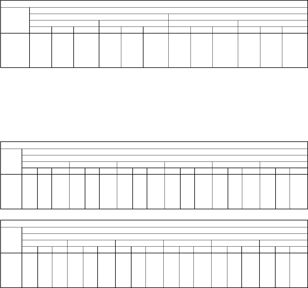
AIR DELIVERY — 558D036-150 HORIZONTAL DISCHARGE UNITS
558D036 (3 TON)
Airflow
(Cfm)
Standard Direct-Drive Motor
Low Speed High Speed
208 v 230, 460, 575 v 208 v 230, 460, 575 v
ESP Bhp Watts ESP Bhp Watts ESP Bhp Watts ESP Bhp Watts
900 0.72 0.21 253 0.75 0.23 277 0.73 0.26 307 0.76 0.31 363
1000 0.67 0.23 270 0.69 0.25 292 0.70 0.27 321 0.71 0.32 374
1100 0.61 0.24 287 0.63 0.26 307 0.64 0.28 335 0.65 0.33 385
1200 0.57 0.26 304 0.58 0.27 323 0.56 0.29 349 0.59 0.34 397
1300 0.51 0.27 321 0.53 0.29 338 0.53 0.31 364 0.54 0.34 408
1400 0.44 0.29 338 0.46 0.30 354 0.47 0.32 378 — — —
1500 0.39 0.30 355 0.41 0.31 369 0.43 0.33 392 — — —
LEGEND
Bhp — Brake Horsepower Input to Fan
ESP — External Static Pressure (in. wg)
FIOP — Factory-Installed Option
Watts — Input Watts to Motor
NOTES:
1. Values include losses for filters, unit casing, and wet coils. See
page 47 for accessory/FIOP static pressure information.
2. Extensive motor and electrical testing on these units ensures that the
full range of the motor can be utilized with confidence. Using
your fan motors up to the wattage ratings shown will not result in nui-
sance tripping or premature motor failure. Unit warranty will not be
affected. For additional information on motor performance, refer to
Evaporator-Fan Motor Performance table on page 62.
3. Use of a field-supplied motor may affect wire sizing. Contact your lo-
cal representative for details.
4. Minimum allowable cfm is 300 cfm/ton.
558D036 (3 TON)
Airflow
(Cfm)
Alternate Belt-Drive Motor
External Static Pressure (in. wg)
0.1 0.2 0.3 0.4 0.5 0.6
Rpm Bhp Watts Rpm Bhp Watts Rpm Bhp Watts Rpm Bhp Watts Rpm Bhp Watts Rpm Bhp Watts
900 526 0.06 70 584 0.08 99 656 0.12 139 734 0.22 219 818 0.25 269 875 0.27 289
1000 570 0.09 109 627 0.13 149 738 0.19 189 800 0.26 259 848 0.29 288 895 0.31 308
1100 614 0.13 149 670 0.16 189 758 0.23 229 812 0.29 288 863 0.32 308 914 0.35 348
1200 658 0.16 189 710 0.23 229 780 0.28 279 840 0.32 318 889 0.36 358 938 0.40 398
1300 703 0.20 239 752 0.27 269 808 0.32 318 868 0.37 368 916 0.41 408 963 0.45 448
1400 725 0.29 288 776 0.31 308 845 0.38 378 891 0.42 418 937 0.47 467 983 0.51 507
1500 755 0.33 328 816 0.38 378 870 0.43 428 924 0.48 477 969 0.53 527 1014 0.58 577
558D036 (3 TON) (cont)
Airflow
(Cfm)
Alternate Belt-Drive Motor
External Static Pressure (in. wg)
0.7 0.8 0.9 1.0 1.1 1.2
Rpm Bhp Watt Rpm Bhp Watts Rpm Bhp Watts Rpm Bhp Watts Rpm Bhp Watts Rpm Bhp Watts
900 924 0.32 308 953 0.35 348 989 0.38 388 1028 0.42 438 1074 0.49 487 1120 0.54 537
1000 936 0.35 348 977 0.39 388 1020 0.44 438 1064 0.48 477 1124 0.54 537 1185 0.60 597
1100 960 0.39 388 1005 0.43 428 1052 0.49 487 1100 0.52 527 1163 0.59 587 1225 0.65 647
1200 960 0.45 388 1038 0.50 497 1076 0.53 527 1136 0.59 577 1201 0.65 647 1266 0.72 716
1300 1012 0.51 507 1061 0.56 557 1090 0.61 607 1172 0.65 647 1239 0.72 716 1306 0.79 786
1400 1027 0.56 557 1071 0.60 597 1108 0.67 666 1208 0.70 706 1278 0.79 786 1347 0.87 865
1500 1056 0.63 627 1097 0.68 676 1117 0.70 696 1245 0.74 776 1315 0.87 865 1385 0.96 955
LEGEND
Bhp — Brake Horsepower Input to Fan
FIOP — Factory-Installed Option
Watts — Input Watts to Motor
NOTES:
1. Boldface indicates a field-supplied drive is required. (See Note 4.)
2. Maximum usable watts input is 1000 and maximum continuous bhp
is 1.00. Extensive motor and electrical testing on these units ensures
that the full range of the motor can be utilized with confidence. Using
your fan motors up to the wattage ratings shown will not result in
nuisance tripping or premature motor failure. Unit warranty will not be
affected. For additional information on motor performance, refer to
Evaporator-Fan Motor Performance table on page 62.
3. Values include losses for filters, unit casing, and wet coils. See
page 47 for accessory/FIOP static pressure information.
4. Motor drive range: 760 to 1000 rpm. All other rpms require field-
supplied drive.
5. Interpolation is permissible. Do not extrapolate.
6. Use of a field-supplied motor may affect wire sizing. Contact your lo-
cal representative for details.
7. Minimum allowable cfm is 300 cfm/ton.
34
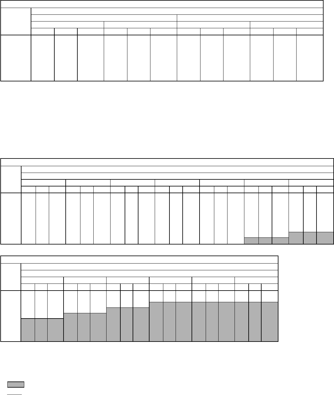
AIR DELIVERY — 558D036-150 HORIZONTAL DISCHARGE UNITS (cont)
558D048 (4 TON)
Airflow
(Cfm)
Standard Direct-Drive Motor
Low Speed High Speed
208 v 230, 460, 575 v 208 v 230, 460, 575 v
ESP Bhp Watts ESP Bhp Watts ESP Bhp Watts ESP Bhp Watts
1200 0.93 0.41 458 0.97 0.45 506 1.04 0.51 572 1.09 0.56 632
1300 0.86 0.42 471 0.90 0.46 521 0.96 0.52 589 1.02 0.58 651
1400 0.78 0.45 503 0.84 0.49 556 0.90 0.54 616 0.96 0.60 681
1500 0.73 0.47 536 0.76 0.52 593 0.83 0.56 631 0.89 0.62 698
1600 0.67 0.49 557 0.70 0.54 616 0.75 0.58 654 0.82 0.64 723
1700 0.60 0.52 584 0.63 0.57 646 0.67 0.60 678 0.74 0.66 750
1800 0.51 0.54 610 0.54 0.60 674 0.62 0.62 698 0.69 0.68 772
1900 0.40 0.56 629 0.45 0.62 696 0.54 0.64 720 0.62 0.70 796
2000 0.32 0.58 661 0.33 0.65 731 0.47 0.66 744 0.54 0.73 823
LEGEND
Bhp — Brake Horsepower Input to Fan
ESP — External Static Pressure (in. wg)
FIOP — Factory-Installed Option
Watts — Input Watts to Motor
NOTES:
1. Values include losses for filters, unit casing, and wet coils. See
page 47 for accessory/FIOP static pressure information.
2. Extensive motor and electrical testing on these units ensures that the
full range of the motor can be utilized with confidence. Using
your fan motors up to the wattage ratings shown will not result in nui-
sance tripping or premature motor failure. Unit warranty will not be
affected. For additional information on motor performance, refer to
Evaporator-Fan Motor Performance table on page 62.
3. Use of a field-supplied motor may affect wire sizing. Contact your lo-
cal representative for details.
4. Minimum allowable cfm is 300 cfm/ton.
558D048 (4 TON)
Airflow
(Cfm)
Alternate Direct-Drive Motor
External Static Pressure (in. wg)
0.1 0.2 0.3 0.4 0.6 0.7 0.8
Rpm Bhp Watts Rpm Bhp Watts Rpm Bhp Watts Rpm Bhp Watts Rpm Bhp Watts Rpm Bhp Watts Rpm Bhp Watts
1200 514 0.15 158 590 0.20 210 657 0.25 263 723 0.30 315 828 0.42 441 876 0.49 510 924 0.55 578
1300 545 0.18 189 615 0.23 242 680 0.29 305 744 0.35 368 849 0.47 494 895 0.54 562 940 0.60 630
1400 577 0.21 221 642 0.27 284 704 0.33 347 766 0.39 410 870 0.52 546 915 0.59 620 959 0.66 693
1500 609 0.26 273 670 0.31 326 729 0.38 394 788 0.44 462 892 0.58 609 936 0.65 683 980 0.72 757
1600 642 0.30 315 699 0.36 378 755 0.43 447 811 0.49 515 913 0.64 672 957 0.72 751 1001 0.79 830
1700 675 0.36 378 728 0.42 441 782 0.49 510 836 0.55 578 935 0.71 746 979 0.79 825 1023 0.86 904
1800 709 0.41 431 759 0.48 504 810 0.55 578 860 0.62 651 957 0.78 820 1001 0.86 904 1044 0.94 988
1900 743 0.48 504 790 0.55 578 838 0.62 651 886 0.69 725 980 0.86 904 1023 0.95 993 1066 1.03 1082
2000 778 0.55 578 836 0.62 651 875 0.70 730 913 0.77 809 1004 0.94 988 1046 1.03 1082 1088 1.12 1177
558D048 (4 TON) (cont)
Airflow
(Cfm)
Alternate Direct-Drive Motor
External Static Pressure (in. wg)
1.0 1.1 1.2 1.4 1.6 1.8
Rpm Bhp Watts Rpm Bhp Watts Rpm Bhp Watts Rpm Bhp Watts Rpm Bhp Watts Rpm Bhp Watts
1200 999 0.66 674 1018 0.67 685 1036 0.68 695 1073 0.71 756 1109 0.75 794 1138 0.79 851
1300 1025 0.74 756 1058 0.79 807 1090 0.84 858 1121 0.87 832 1159 0.90 918 1193 0.95 976
1400 1042 0.81 828 1080 0.88 899 1118 0.95 971 1175 1.06 1014 1206 1.09 1042 1244 1.12 1138
1500 1060 0.88 899 1098 0.96 981 1136 1.04 1063 1205 1.19 1138 1258 1.30 1243 1289 1.34 1282
1600 1080 0.95 971 1117 1.04 1058 1153 1.12 1140 1224 1.29 1234 1287 1.45 1387 1337 1.56 1492
1700 1101 1.03 1053 1137 1.12 1139 1172 1.20 1226 1241 1.38 1320 1307 1.56 1492 1366 1.73 1655
1800 1122 1.11 1134 1157 1.20 1226 1192 1.29 1318 1258 1.48 1415 1323 1.67 1597 1385 1.86 1779
1900 1143 1.21 1237 1179 1.30 1328 1214 1.39 1420 1279 1.58 1511 1341 1.78 1702 1402 1.98 1894
2000 1165 1.31 1339 1200 1.40 1431 1235 1.49 1523 1300 1.69 1616 1361 1.90 1817 1419 2.10 2008
LEGEND
Bhp — Brake Horsepower Input to Fan
FIOP — Factory-Installed Option
Watts — Input Watts to Motor
NOTES:
1. Boldface indicates a field-supplied drive is required. (See Note 7.)
2. indicates field-supplied motor and drive are required.
3. indicates maximum usable bhp/watts.
4. Maximum usable watts input is 1000 and maximum continuous bhp
is 1.00. Extensive motor and electrical testing on these units ensures
that the full range of the motor can be utilized with confidence. Using
your fan motors up to the wattage ratings shown will not result in
nuisance tripping or premature motor failure. Unit warranty will not be
affected. For additional information on motor performance, refer to
Evaporator-Fan Motor Performance table on page 62.
5. Values include losses for filters, unit casing, and wet coils. See
page 47 for accessory/FIOP static pressure information.
6. Use of a field-supplied motor may affect wire sizing. Contact your lo-
cal representative for details.
7. Motor drive range: 835 to 1185 rpm. All other rpms require field-
supplied drive.
8. Interpolation is permissible. Do not extrapolate.
9. Minimum allowable cfm is 300 cfm/ton.
35
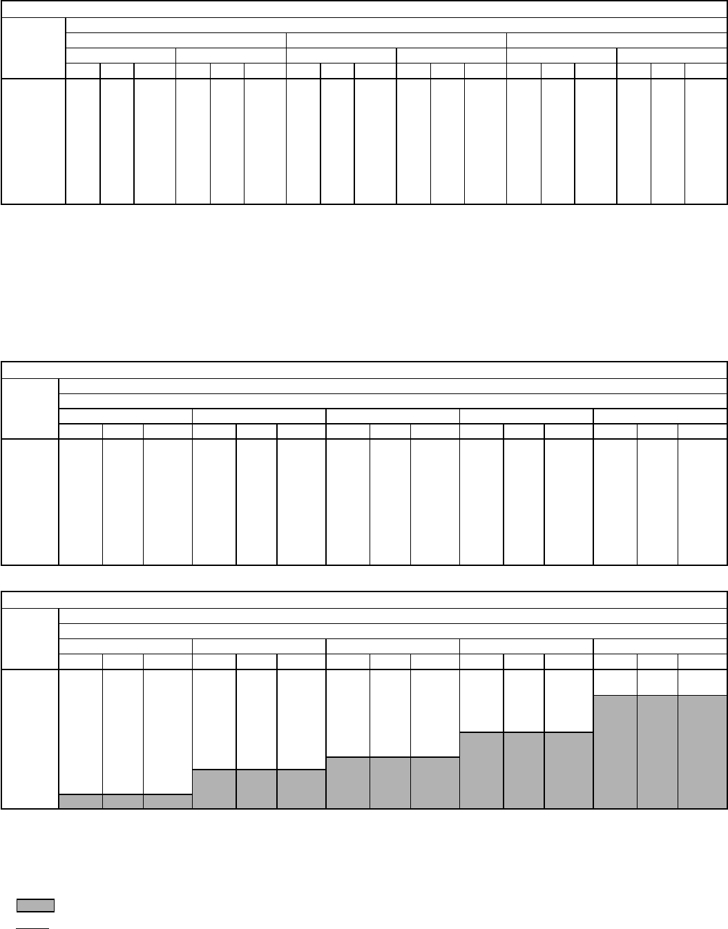
AIR DELIVERY — 558D036-150 HORIZONTAL DISCHARGE UNITS (cont)
558D060 (5 TON)
AIRFLOW
(Cfm)
Standard Direct-Drive Motor
Low Speed Medium Speed High Speed
208 v 230, 460, 575 v 208 v 230, 460, 575 v 208 v 230, 460, 575 v
ESP Bhp Watts ESP Bhp Watts ESP Bhp Watts ESP Bhp Watts ESP Bhp Watts ESP Bhp Watts
1500 1.01 0.67 750 1.25 0.71 791 1.26 0.70 782 1.46 0.76 845 1.46 0.79 875 1.52 0.85 949
1600 0.82 0.70 780 1.09 0.74 824 1.11 0.74 821 1.32 0.79 883 1.33 0.82 913 1.41 0.89 988
1700 0.64 0.73 810 0.97 0.77 857 0.99 0.77 861 1.22 0.83 921 1.24 0.85 950 1.33 0.92 1027
1800 0.44 0.75 839 0.81 0.80 891 0.84 0.80 900 1.09 0.86 959 1.11 0.89 988 1.22 0.96 1066
1900 0.32 0.78 869 0.66 0.83 924 0.69 0.83 940 0.96 0.90 997 0.99 0.92 1025 1.11 0.99 1105
2000 0.21 0.81 899 0.47 0.86 957 0.51 0.86 979 0.80 0.93 1035 0.83 0.95 1063 0.97 1.03 1144
2100 0.13 0.83 929 0.32 0.89 990 0.36 0.89 1018 0.64 0.96 1073 0.71 0.99 1101 0.86 1.06 1183
2200 0.05 0.86 959 0.19 0.92 1023 0.21 0.92 1058 0.50 1.00 1111 0.58 1.02 1138 0.75 1.10 1222
2300 — — — 0.08 0.95 1057 0.08 0.95 1097 0.34 1.03 1149 0.39 1.06 1176 0.57 1.13 1261
2400 — — — — — — — — — 0.24 1.07 1187 0.29 1.09 1213 0.49 1.17 1300
2500 — — — — — — — — — 0.15 1.10 1225 0.15 1.12 1251 0.34 1.20 1340
LEGEND
Bhp — Brake Horsepower Input to Fan
ESP — External Static Pressure (in. wg)
FIOP — Factory-Installed Option
Watts — Input Watts to Motor
NOTES:
1. Values include losses for filters, unit casing, and wet coils. See
page 47 for accessory/FIOP static pressure information.
2. Extensive motor and electrical testing on these units ensures that the
full range of the motor can be utilized with confidence. Using
your fan motors up to the wattage ratings shown will not result in nui-
sance tripping or premature motor failure. Unit warranty will not be
affected. For additional information on motor performance, refer to
Evaporator-Fan Motor Performance table on page 62.
3. Use of a field-supplied motor may affect wire sizing. Contact your lo-
cal representative for details.
4. Minimum allowable cfm is 300 cfm/ton.
558D060 (5 TON)
Airflow
(Cfm)
Alternate Belt-Drive Motor
External Static Pressure (in. wg)
0.1 0.2 0.4 0.6 0.8
Rpm Bhp Watts Rpm Bhp Watts Rpm Bhp Watts Rpm Bhp Watts Rpm Bhp Watts
1500 658 0.27 276 722 0.33 337 840 0.46 470 937 0.59 603 1027 0.74 756
1600 693 0.32 327 754 0.38 388 867 0.52 531 963 0.65 664 1052 0.81 828
1700 729 0.38 388 787 0.44 450 895 0.58 593 991 0.73 746 1075 0.88 899
1800 765 0.45 460 821 0.51 521 923 0.65 664 1019 0.81 828 1099 0.96 981
1900 802 0.52 531 854 0.58 593 953 0.73 746 1046 0.90 920 1126 1.06 1083
2000 840 0.60 613 900 0.66 674 984 0.82 838 1073 0.99 1012 1154 1.16 1185
2100 878 0.69 705 923 0.75 766 1015 0.91 930 1101 1.08 1104 1182 1.27 1298
2200 916 0.78 797 958 0.85 869 1046 1.01 1032 1129 1.19 1216 1209 1.39 1420
2300 954 0.89 910 993 0.96 981 1079 1.13 1155 1160 1.31 1339 1237 1.51 1543
2400 993 1.00 1022 1029 1.07 1093 1112 1.25 1277 1190 1.43 1461 1264 1.63 1666
2500 1031 1.13 1155 1066 1.20 1226 1145 1.39 1420 1220 1.57 1604 1292 1.77 1809
558D060 (5 TON) (cont)
Airflow
(Cfm)
Alternate Belt-Drive Motor
External Static Pressure (in. wg)
1.0 1.2 1.4 1.6 1.8
Rpm Bhp Watts Rpm Bhp Watts Rpm Bhp Watts Rpm Bhp Watts Rpm Bhp Watts
1500 1108 0.90 920 1186 1.08 1104 1263 1.30 1328 1343 1.58 1615 1431 1.79 1829
1600 1130 0.97 991 1205 1.15 1175 1278 1.35 1380 1350 1.61 1645 1424 1.80 1921
1700 1154 1.06 1083 1226 1.23 1257 1296 1.42 1451 1364 1.64 1676 1432 1.89 1931
1800 1178 1.14 1165 1249 1.32 1349 1316 1.52 1553 1382 1.72 1758 1447 1.95 1993
1900 1201 1.23 1257 1274 1.43 1461 1338 1.62 1656 1402 1.80 1870 1464 2.05 2095
2000 1226 1.33 1359 1297 1.53 1564 1363 1.73 1768 1424 1.94 1983 1484 2.16 2207
2100 1252 1.45 1482 1320 1.64 1676 1388 1.80 1891 1448 2.07 2115 1505 2.29 2340
2200 1280 1.58 1615 1345 1.77 1809 1410 1.97 2013 1473 2.20 2248 1529 2.43 2483
2300 1309 1.71 1747 1372 1.91 1952 1434 2.11 2156 1496 2.34 2391 1554 2.58 2637
2400 1336 1.80 1891 1400 2.06 2105 1459 2.26 2310 1519 2.48 2534 1578 2.76 2820
2500 1363 2.00 2044 1428 2.22 2269 1486 2.43 2483 1543 2.65 2708 1600 2.89 2953
LEGEND
Bhp — Brake Horsepower Input to Fan
FIOP — Factory-Installed Option
Watts — Input Watts to Motor
NOTES:
1. Boldface indicates a field-supplied drive is required. (See Note 7.)
2. indicates field-supplied motor and drive are required.
3. indicates maximum usable bhp/watts.
4. Maximum usable watts input is 1921 and maximum continuous bhp
is 1.80. Extensive motor and electrical testing on these units ensures
that the full range of the motor can be utilized with confidence. Using
your fan motors up to the wattage ratings shown will not result in
nuisance tripping or premature motor failure. Unit warranty will not be
affected. For additional information on motor performance, refer to
Evaporator-Fan Motor Performance table on page 62.
5. Values include losses for filters, unit casing, and wet coils. See
page 47 for accessory/FIOP static pressure information.
6. Use of a field-supplied motor may affect wire sizing. Contact your lo-
cal representative for details.
7. Motor drive range: 900 to 1300 rpm. All other rpms require field-
supplied drive.
8. Interpolation is permissible. Do not extrapolate.
9. Minimum allowable cfm is 300 cfm/ton.
36
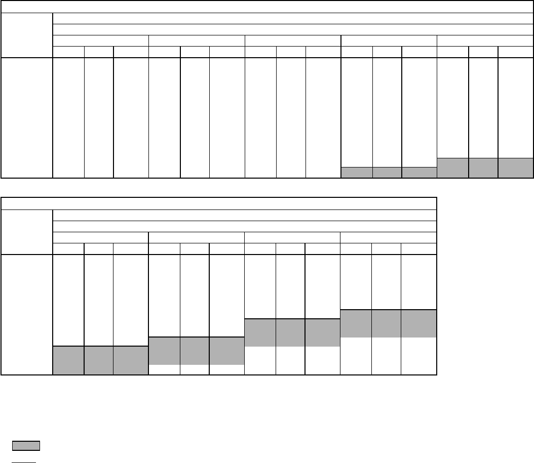
AIR DELIVERY — 558D036-150 HORIZONTAL DISCHARGE UNITS (cont)
558D072 (6 TON)
AIRFLOW
(Cfm)
Standard Belt-Drive Motor
External Static Pressure (in. wg)
0.1 0.2 0.4 0.6 0.8
Rpm Bhp Watts Rpm Bhp Watts Rpm Bhp Watts Rpm Bhp Watts Rpm Bhp Watts
1800 765 0.45 487 821 0.51 532 923 0.65 638 1019 0.81 843 1099 0.96 883
1900 802 0.45 539 854 0.58 585 953 0.73 700 1046 0.90 835 1126 1.06 965
2000 840 0.60 600 888 0.66 646 984 0.82 771 1073 0.99 907 1154 1.16 1047
2100 878 0.69 669 923 0.75 716 1015 0.91 843 1101 1.08 981 1182 1.27 1140
2200 916 0.78 739 958 0.85 795 1046 1.01 924 1129 1.19 1072 1209 1.39 1241
2300 954 0.89 827 993 0.96 883 1079 1.13 1022 1160 1.31 1173 1237 1.51 1344
2400 993 1.00 916 1029 1.07 973 1112 1.25 1123 1190 1.43 1275 1264 1.63 1447
2500 1031 1.13 1022 1066 1.20 1081 1145 1.39 1241 1220 1.57 1396 1292 1.77 1569
2600 1070 1.26 1131 1103 1.34 1199 1179 1.52 1353 1251 1.71 1517 1322 1.92 1700
2700 1109 1.41 1258 1140 1.48 1318 1212 1.67 1482 1283 1.87 1656 1352 2.09 1849
2800 1148 1.57 1396 1177 1.64 1456 1246 1.83 1621 1316 2.04 1805 1383 2.26 1997
2900 1188 1.74 1543 1215 1.81 1604 1281 2.00 1770 1349 2.22 1962 1413 2.44 2154
3000 1227 1.92 1700 1253 2.00 1770 1316 2.19 1936 1382 2.42 2136 1444 2.63 2317
558D072 (6 TON) (cont)
AIRFLOW
(Cfm)
Standard Belt-Drive Motor
External Static Pressure (in. wg)
1.0 1.2 1.4 1.6
Rpm Bhp Watts Rpm Bhp Watts Rpm Bhp Watts Rpm Bhp Watts
1800 1178 1.14 1031 1249 1.32 1182 1316 1.52 1353 1382 1.72 1526
1900 1201 1.23 1106 1274 1.43 1275 1338 1.62 1439 1402 1.83 1621
2000 1226 1.33 1990 1297 1.53 1361 1363 1.73 1534 1424 1.94 1718
2100 1252 1.45 1292 1320 1.64 1456 1388 1.85 1639 1448 2.07 1831
2200 1280 1.58 1404 1345 1.77 1569 1410 1.97 1744 1473 2.20 1945
2300 1309 1.71 1517 1372 1.91 1691 1434 2.11 1866 1496 2.34 2067
2400 1336 1.85 1639 1400 2.06 1823 1459 2.26 1997 1519 2.48 2188
2500 1363 2.00 1770 1428 2.22 1962 1486 2.43 2145 1543 2.65 2335
2600 1390 2.15 1901 1456 2.38 2102 1514 2.61 2300 1569 2.83 2487
2700 1418 2.31 2041 1483 2.56 2257 1543 2.80 2462 — — —
2800 1446 2.48 2188 1510 2.73 2403 — — — — — —
2900 1476 2.67 2352 1537 2.92 2562 — — — — — —
3000 1506 2.88 2529 — — — — — — — — —
LEGEND
Bhp — Brake Horsepower Input to Fan
FIOP — Factory-Installed Option
Watts — Input Watts to Motor
NOTES:
1. Boldface indicates a field-supplied drive is required. (See Note 7.)
2. indicates field-supplied motor and drive are required.
3. indicates maximum usable bhp/watts.
4. Maximum usable watts input is 2120 and maximum continuous bhp
is 2.40. Extensive motor and electrical testing on these units ensures
that the full range of the motor can be utilized with confidence. Using
your fan motors up to the wattage ratings shown will not result in nui-
sance tripping or premature motor failure. Unit warranty will not be
affected. For additional information on motor performance, refer to
Evaporator-Fan Motor Performance table on page 62.
5. Values include losses for filters, unit casing, and wet coils. See
page 47 for accessory/FIOP static pressure information.
6. Use of a field-supplied motor may affect wire sizing. Contact your lo-
cal representative for details.
7. Standard motor drive range: 1070 to 1460 rpm. All other rpms re-
quire field-supplied drive.
8. Interpolation is permissible. Do not extrapolate.
9. Minimum allowable cfm is 300 cfm/ton.
37
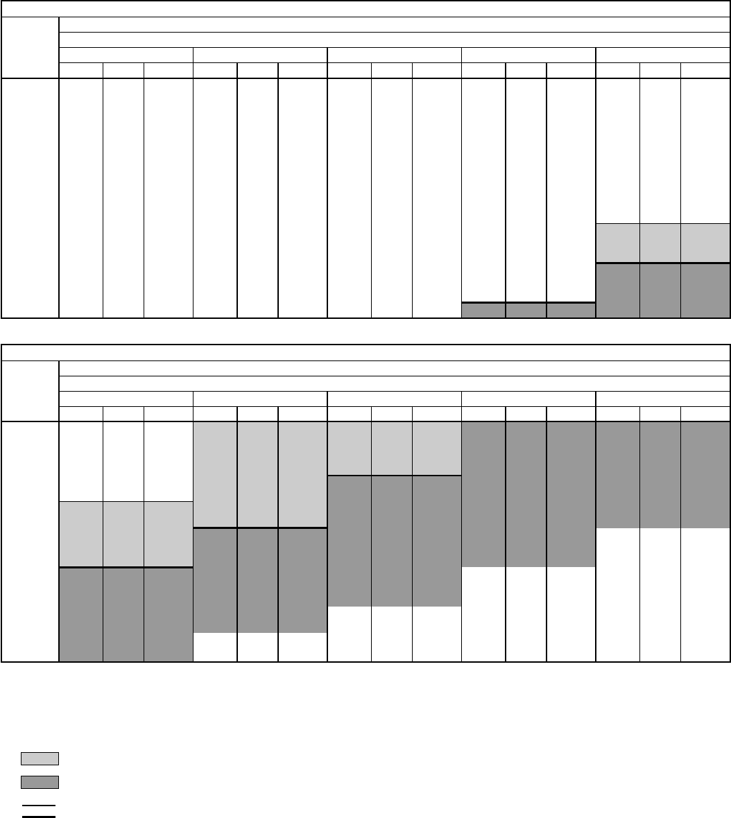
AIR DELIVERY — 558D036-150 HORIZONTAL DISCHARGE UNITS (cont)
558D090 (7
1
⁄
2
TON)
Airflow
(Cfm)
Standard Belt-Drive Motor
External Static Pressure (in. wg)
0.2 0.4 0.6 0.8 1.0
Rpm Bhp Watts Rpm Bhp Watts Rpm Bhp Watts Rpm Bhp Watts Rpm Bhp Watts
2250 465 0.43 473 554 0.64 630 630 0.86 803 695 1.09 989 757 1.34 1199
2300 471 0.45 487 559 0.66 646 635 0.89 827 699 1.12 1014 760 1.37 1224
2400 482 0.50 524 569 0.71 684 645 0.95 875 708 1.18 1064 768 1.44 1284
2500 494 0.54 554 581 0.76 723 654 1.01 924 717 1.25 1123 776 1.51 1344
2550 501 0.57 577 587 0.79 747 659 1.05 956 722 1.29 1156 780 1.55 1378
2660 507 0.59 592 592 0.82 771 663 1.08 981 727 1.32 1182 784 1.58 1404
2700 520 0.65 638 604 0.89 827 672 1.14 1031 737 1.40 1250 793 1.66 1473
2800 533 0.71 684 615 0.95 875 683 1.20 1081 747 1.49 1327 802 1.75 1552
2900 546 0.77 731 626 1.02 932 693 1.27 1140 756 1.57 1396 813 1.84 1630
3000 559 0.83 779 637 1.09 989 704 1.35 1207 765 1.66 1473 823 1.94 1718
3100 572 0.90 835 648 1.17 1056 715 1.43 1275 775 1.74 1543 832 2.05 1814
3200 585 0.96 883 660 1.24 1114 727 1.52 1353 785 1.83 1321 841 2.15 1901
3300 598 1.03 940 671 1.32 1182 739 1.62 1439 795 1.91 1691 851 2.26 1997
3400 610 1.10 998 682 1.41 1258 750 1.72 1526 806 2.01 1779 860 2.36 2084
3500 623 1.17 1056 694 1.50 1335 761 1.82 1613 817 2.11 1866 870 2.47 2180
3600 636 1.25 1123 707 1.60 1422 772 1.93 1709 828 2.23 1971 880 2.57 2266
3700 649 1.33 1190 720 1.71 1517 783 2.03 1796 840 2.35 2076 890 2.69 2369
3750 655 1.37 1224 727 1.77 1569 789 2.09 1849 846 2.42 2136 896 2.75 2420
558D090 (7
1
⁄
2
TON) (cont)
Airflow
(Cfm)
Standard Belt-Drive Motor
External Static Pressure (in. wg)
1.2 1.4 1.6 1.8 2.0
Rpm Bhp Watts Rpm Bhp Watts Rpm Bhp Watts Rpm Bhp Watts Rpm Bhp Watts
2250 810 1.62 1439 850 1.91 1691 873 2.20 1945 863 2.50 2206 855 2.78 2445
2300 816 1.65 1465 859 1.94 1718 888 2.24 1980 897 2.55 2249 887 2.85 2504
2400 824 1.72 1526 872 2.01 1779 909 2.32 2050 931 2.64 2326 935 2.96 2595
2500 832 1.79 1587 882 2.09 1849 925 2.40 2119 955 2.72 2394 972 3.06 2678
2550 836 1.83 1621 887 2.13 1884 931 2.45 2162 964 2.77 2436 986 3.11 2718
2660 839 1.87 1656 891 2.17 1919 936 2.49 2197 973 2.82 2479 999 3.16 2759
2700 846 1.95 1726 898 2.26 1997 946 2.58 2275 987 2.91 2554 1019 3.26 2839
2800 855 2.04 1805 906 2.35 2076 954 2.67 2352 997 3.01 2637 1034 3.36 2917
2900 863 2.13 1884 913 2.44 2154 961 2.77 2436 1006 3.12 2727 — — —
3000 872 2.22 1962 921 2.54 2240 969 2.88 2529 1014 3.22 2807 — — —
3100 882 2.33 2058 930 2.65 2335 976 2.99 2620 1021 3.34 2902 — — —
3200 892 2.45 2162 939 2.76 2428 984 3.10 2710 — — — — — —
3300 902 2.57 2266 948 2.88 2529 993 3.21 2799 — — — — — —
3400 912 2.69 2369 958 3.01 2637 1002 3.34 2902 — — — — — —
3500 921 2.82 2479 968 3.15 2751 — — — — — — — — —
3600 930 2.95 2587 978 3.29 2862 — — — — — — — — —
3700 940 3.07 2686 — — — — — — — — — — — —
3750 945 3.14 2743 — — — — — — — — — — — —
LEGEND
Bhp — Brake Horsepower Input to Fan
FIOP — Factory-Installed Option
Watts — Input Watts to Motor
NOTES:
1. Boldface indicates a field-supplied drive is required. (See Note 9.)
2. indicates alternate drive is required.
3. indicates field-supplied motor and drive are required.
4. indicates maximum usable bhp/watts of standard drive.
5. indicates maximum usable bhp/watts of alternate drive.
6. Maximum usable watts input is 2120 and maximum continuous bhp
is 2.40. Extensive motor and electrical testing on these units
ensures that the full range of the motor can be utilized with confi-
dence. Using your fan motors up to the wattage ratings shown will
not result in nuisance tripping or premature motor failure. Unit war-
ranty will not be affected. For additional information on motor per-
formance, refer to Evaporator-Fan Motor Performance table on
page 62.
7. Values include losses for filters, unit casing, and wet coils. See
page 47 for accessory/FIOP static pressure information.
8. Use of a field-supplied motor may affect wire sizing. Contact your
local representative for details.
9. Standard drive range: 590 to 840 rpm. Alternate drive range: 685 to
935 rpm. All other rpms require field-supplied drive.
10. Interpolation is permissible. Do not extrapolate.
11. Minimum allowable cfm is 300 cfm/ton.
38
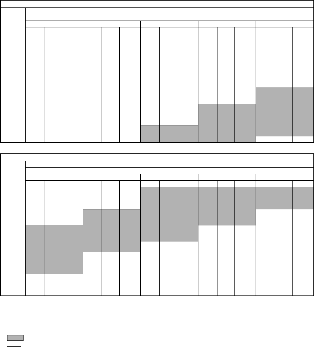
AIR DELIVERY — 558D036-150 HORIZONTAL DISCHARGE UNITS (cont)
558D102 (8
1
⁄
2
TON)
Airflow
(Cfm)
Standard Belt-Drive Motor
External Static Pressure (in. wg)
0.2 0.4 0.6 0.8 1.0
Rpm Bhp Watts Rpm Bhp Watts Rpm Bhp Watts Rpm Bhp Watts Rpm Bhp Watts
2550 501 0.57 577 587 0.79 747 659 1.05 956 722 1.29 1156 780 1.55 1378
2660 507 0.59 592 592 0.82 771 663 1.08 981 727 1.32 1182 784 1.58 1404
2700 520 0.65 638 604 0.89 827 672 1.14 1031 737 1.40 1250 793 1.66 1473
2800 533 0.71 684 615 0.95 875 683 1.20 1081 747 1.49 1327 802 1.75 1552
2900 546 0.77 731 626 1.02 932 693 1.27 1140 756 1.57 1396 813 1.84 1630
3000 559 0.83 779 637 1.09 989 704 1.35 1207 765 1.66 1473 823 1.94 1718
3100 572 0.90 835 648 1.17 1056 715 1.43 1275 775 1.74 1543 832 2.05 1814
3200 585 0.96 883 660 1.24 1114 727 1.52 1353 785 1.83 1321 841 2.15 1901
3300 598 1.03 940 671 1.32 1182 739 1.62 1439 795 1.91 1691 851 2.26 1997
3400 610 1.10 998 682 1.41 1258 750 1.72 1526 806 2.01 1779 860 2.36 2084
3500 623 1.17 1056 694 1.50 1335 761 1.82 1613 817 2.11 1866 870 2.47 2180
3600 636 1.25 1123 707 1.60 1422 772 1.93 1709 828 2.23 1971 880 2.57 2266
3700 649 1.33 1190 720 1.71 1517 783 2.03 1796 840 2.35 2076 890 2.69 2369
3750 655 1.37 1224 727 1.77 1569 789 2.09 1849 846 2.42 2136 896 2.75 2420
3800 661 1.41 1258 733 1.82 1613 795 2.15 1901 852 2.48 2188 901 2.80 2462
3900 674 1.49 1327 746 1.93 1709 806 2.26 1997 863 2.61 2300 912 2.93 2571
4000 687 1.57 1396 759 2.05 1814 817 2.38 2102 874 2.75 2420 923 3.08 2694
4100 699 1.60 1473 772 2.17 1919 828 2.50 2206 885 2.88 2529 935 3.23 2815
4200 712 1.75 1552 785 2.30 2032 840 2.64 2326 897 3.03 2653 947 3.39 2940
4250 719 1.80 1595 792 2.37 2093 846 2.71 2386 903 3.10 2710 — — —
558D102 (8
1
⁄
2
TON) (cont)
Airflow
(Cfm)
Standard Belt-Drive Motor
External Static Pressure (in. wg)
1.2 1.4 1.6 1.8 2.0
Rpm Bhp Watts Rpm Bhp Watts Rpm Bhp Watts Rpm Bhp Watts Rpm Bhp Watts
2550 836 1.83 1621 887 2.13 1884 931 2.45 2162 964 2.77 2436 986 3.11 2718
2660 839 1.87 1656 891 2.17 1919 936 2.49 2197 973 2.82 2479 999 3.16 2759
2700 846 1.95 1726 898 2.26 1997 946 2.58 2275 987 2.91 2554 1019 3.26 2839
2800 855 2.04 1805 906 2.35 2076 954 2.67 2352 997 3.01 2637 1034 3.36 2917
2900 863 2.13 1884 913 2.44 2154 961 2.77 2436 1006 3.12 2727 — — —
3000 872 2.22 1962 921 2.54 2240 969 2.88 2529 1014 3.22 2807 — — —
3100 882 2.33 2058 930 2.65 2335 976 2.99 2620 1021 3.34 2902 — — —
3200 892 2.45 2162 939 2.76 2428 984 3.10 2710 — — — — — —
3300 902 2.57 2266 948 2.88 2529 993 3.21 2799 — — — — — —
3400 912 2.69 2369 958 3.01 2637 1002 3.34 2902 — — — — — —
3500 921 2.82 2479 968 3.15 2751 — — — — — — — — —
3600 930 2.95 2587 978 3.29 2862 — — — — — — — — —
3700 940 3.07 2686 — — — — — — — — — — — —
3750 945 3.14 2743 — — — — — — — — — — — —
3800 949 3.20 2781 — — — — — — — — — — — —
3900 959 3.33 2894 — — — — — — — — — — — —
4000 ——— ——— —————————
4100 ——— ——— —————————
4200 ——— ——— —————————
4250 ——— ——— ————————
LEGEND
Bhp — Brake Horsepower Input to Fan
FIOP — Factory-Installed Option
Watts — Input Watts to Motor
NOTES:
1. Boldface indicates a field-supplied drive is required. (See Note 7.)
2. indicates field-supplied motor and drive are required.
3. indicates maximum usable bhp/watts.
4. Maximum usable watts input is 2120 and maximum continuous bhp
is 2.40. Extensive motor and electrical testing on these units ensures
that the full range of the motor can be utilized with confidence. Using
your fan motors up to the wattage ratings shown will not result in nui-
sance tripping or premature motor failure. Unit warranty will not be
affected. For additional information on motor performance, refer to
Evaporator-Fan Motor Performance table on page 62.
5. Values include losses for filters, unit casing, and wet coils. See
page 47 for accessory/FIOP static pressure information.
6. Use of a field-supplied motor may affect wire sizing. Contact your lo-
cal representative for details.
7. Motor drive range: 685 to 935 rpm. All other rpms require field-
supplied drive.
8. Interpolation is permissible. Do not extrapolate.
9. Minimum allowable cfm is 300 cfm/ton.
39
AIR DELIVERY — 558D036-150 HORIZONTAL DISCHARGE UNITS (cont)
558D120 (10 TON)
Airflow
(Cfm)
Standard and Alternate Belt-Drive Motors
External Static Pressure (in. wg)
0.2 0.4 0.6 0.8 1.0
Rpm Bhp Watts Rpm Bhp Watts Rpm Bhp Watts Rpm Bhp Watts Rpm Bhp Watts
3000 484 0.55 562 560 0.70 677 631 0.87 810 690 1.03 940 747 1.20 1081
3100 495 0.61 607 570 0.76 723 638 0.92 851 699 1.10 998 755 1.27 1140
3200 505 0.66 646 579 0.81 763 646 0.98 899 708 1.16 1047 761 1.34 1199
3300 516 0.72 692 589 0.87 810 655 1.05 956 717 1.23 1106 767 1.40 1250
3400 527 0.78 739 599 0.93 859 664 1.11 1006 724 1.30 1165 775 1.48 1318
3500 537 0.85 795 609 0.99 907 672 1.18 1064 731 1.36 1216 784 1.56 1387
3600 548 0.92 851 619 1.05 956 680 1.24 1114 738 1.43 1275 794 1.64 1456
3700 560 1.00 916 629 1.12 1014 688 1.31 1173 747 1.51 1344 802 1.73 1534
3800 571 1.08 981 639 1.19 1072 698 1.39 1241 756 1.60 1422 810 1.81 1604
3900 582 1.16 1047 649 1.27 1140 708 1.47 1310 764 1.69 1499 816 1.89 1674
4000 593 1.25 1123 659 1.35 1207 717 1.56 1387 773 1.78 1578 823 1.98 1753
4100 605 1.35 1207 670 1.44 1284 727 1.65 1465 781 1.86 1648 832 2.08 1840
4200 616 1.45 1292 680 1.53 1361 737 1.74 1543 789 1.95 1726 841 2.18 1927
4300 628 1.56 1387 690 1.63 1447 747 1.83 1621 798 2.05 1814 849 2.30 2032
4400 639 1.67 1482 701 1.73 1534 757 1.92 1700 807 2.16 1910 858 2.41 2177
4500 651 1.78 1578 712 1.84 1630 767 2.02 1788 817 2.27 2006 866 2.51 2265
4600 662 1.91 1691 722 1.95 1726 777 2.13 1884 827 2.38 2102 874 2.62 2362
4700 674 2.03 1796 733 2.07 1831 787 2.24 1980 836 2.50 2256 882 2.73 2460
4800 686 2.17 1919 744 2.20 1945 797 2.36 2084 846 2.62 2362 891 2.85 2569
4900 698 2.31 2041 755 2.33 2058 808 2.48 2238 856 2.73 2460 900 2.99 2698
5000 710 2.45 2212 766 2.47 2230 818 2.61 2353 866 2.86 2578 910 3.12 2819
558D120 (10 TON) (cont)
Airflow
(Cfm)
Standard and Alternate Belt-Drive Motors
External Static Pressure (in. wg)
1.2 1.4 1.6 1.8 2.0
Rpm Bhp Watts Rpm Bhp Watts Rpm Bhp Watts Rpm Bhp Watts Rpm Bhp Watts
3000 800 1.38 1233 850 1.52 1353 879 1.38 1233 925 1.81 1604 964 1.92 1761
3100 805 1.44 1284 857 1.63 1447 896 1.66 1473 935 1.93 1709 975 1.98 1811
3200 812 1.51 1344 862 1.71 1517 908 1.85 1639 944 2.01 1836 984 2.09 1903
3300 819 1.59 1413 867 1.78 1578 915 1.98 1753 952 2.11 1920 993 2.22 2014
3400 827 1.67 1482 873 1.85 1639 920 2.07 1831 963 2.21 2005 1001 2.31 2091
3500 833 1.75 1552 880 1.94 1718 926 2.15 1901 970 2.41 2134 1007 2.46 2221
3600 840 1.83 1621 888 2.04 1805 931 2.23 1971 976 2.47 2230 1017 2.62 2362
3700 847 1.92 1700 895 2.13 1884 938 2.33 2108 981 2.56 2309 1024 2.77 2496
3800 856 2.02 1788 901 2.23 1971 945 2.44 2203 986 2.65 2389 1029 2.89 2605
3900 865 2.12 1875 908 2.32 2050 953 2.55 2300 993 2.75 2478 1034 3.00 2707
4000 875 2.22 1962 915 2.42 2186 960 2.65 2389 1000 2.87 2587 1039 3.10 2800
4100 883 2.32 2050 924 2.54 2291 966 2.76 2487 1008 2.99 2698 1046 3.21 2904
4200 889 2.41 2177 934 2.65 2389 972 2.87 2587 1015 3.12 2819 1053 3.34 3029
4300 896 2.51 2265 943 2.77 2406 980 2.99 2698 1021 3.23 2923 1061 3.48 3166
4400 903 2.62 2362 951 2.89 2603 990 3.12 2819 1028 3.36 3049 1068 3.61 3241
4500 912 2.74 2469 958 3.00 2707 999 3.26 2982 1035 3.51 3161 1074 3.74 3346
4600 921 2.87 2587 965 3.11 2810 1008 3.39 3078 1041 3.68 3295 1081 3.90 3450
4700 930 3.00 2707 972 3.23 2923 1017 3.45 3224 1048 3.80 3436 1088 4.13 3552
4800 938 3.14 2838 980 3.37 3058 1025 3.55 3362 1055 3.85 3584 1095 4.30 3653
4900 946 3.27 2962 990 3.51 3149 1034 3.71 3505 1062 3.98 3741 1101 4.45 3753
5000 954 3.39 3078 998 3.62 3271 1042 3.85 3654 1068 4.08 3907 1108 4.59 3851
LEGEND
Bhp — Brake Horsepower Input to Fan
FIOP — Factory-Installed Option
Watts — Input Watts to Motor
NOTES:
1. Boldface indicates a field-supplied or alternate (as appropriate)
drive is required. (See Note 9.)
2. indicates an alternate motor and drive are required.
3. indicates field-supplied motor and drive are required.
4. indicates maximum usable bhp/watts of standard motor.
5. indicates maximum usable bhp/watts of alternate motor.
6. Maximum usable watts input is 2120 with standard motor and 2615
with alternate motor. Maximum continuous bhp is 2.40 with
standard motor and 2.90 with alternate motor. Extensive motor and
electrical testing on these units ensures that the full range of the
motor can be utilized with confidence. Using your fan motors up to
the wattage ratings shown will not result in nuisance tripping or pre-
mature motor failure. Unit warranty will not be affected.
7. Values include losses for filters, unit casing, and wet coils. See
page 47 for accessory/FIOP static pressure information.
8. Use of a field-supplied motor may affect wire sizing. Contact your
local representative for details. For additional information on motor
performance, refer to Evaporator-Fan Motor Performance table on
page 62.
9. Standard motor drive range: 685 to 935 rpm. Alternate motor drive
range: 835 to 1085 rpm. All other rpms require field-supplied drive.
10. Interpolation is permissible. Do not extrapolate.
11. Minimum allowable cfm is 300 cfm/ton.
40
AIR DELIVERY — 558D036-150 HORIZONTAL DISCHARGE UNITS (cont)
558D150 (12
1
⁄
2
TON)
Airflow
(Cfm)
Standard and Alternate Belt-Drive Motors
External Static Pressure (in. wg)
0.2 0.4 0.6 0.8 1.0
Rpm Bhp Watts Rpm Bhp Watts Rpm Bhp Watts Rpm Bhp Watts Rpm Bhp Watts
3750 614 1.01 979 676 1.22 1142 737 1.41 1300 789 1.61 1465 838 1.78 1603
3800 621 1.05 1010 681 1.25 1170 742 1.45 1332 795 1.66 1506 842 1.82 1641
3900 636 1.13 1073 693 1.32 1226 751 1.53 1398 808 1.76 1590 851 1.92 1725
4000 650 1.21 1137 705 1.40 1291 761 1.61 1464 819 1.86 1674 861 2.02 1811
4100 665 1.30 1210 717 1.48 1357 772 1.71 1548 830 1.96 1759 871 2.13 1905
4200 680 1.39 1283 728 1.57 1431 783 1.81 1632 839 2.05 1836 883 2.25 2009
4300 696 1.49 1365 739 1.66 1506 794 1.91 1717 848 2.14 1914 896 2.38 2123
4400 711 1.60 1456 750 1.75 1582 805 2.02 1811 857 2.24 2000 908 2.51 2237
4500 727 1.70 1540 762 1.85 1666 817 2.12 1897 867 2.35 2096 919 2.63 2343
4600 742 1.82 1641 774 1.96 1759 828 2.23 1992 877 2.46 2193 929 2.75 2450
4700 758 1.94 1742 786 2.07 1854 840 2.34 2088 888 2.59 2307 938 2.87 2557
4800 773 2.06 1845 799 2.18 1948 852 2.46 2193 899 2.72 2423 947 2.98 2656
4900 789 2.19 1957 812 2.30 2053 863 2.57 2290 910 2.86 2548 957 3.11 2773
5000 805 2.32 2070 826 2.43 2166 875 2.70 2405 921 2.99 2665 966 3.24 2891
5100 821 2.47 2202 840 2.57 2290 887 2.83 2521 932 3.13 2792 976 3.38 3019
5200 837 2.61 2325 854 2.71 2414 898 2.96 2638 943 3.28 2928 987 3.53 3157
5300 853 2.76 2459 868 2.85 2539 909 3.09 2755 955 3.42 3056 998 3.69 3304
5400 869 2.92 2602 882 3.01 2683 920 3.24 2891 967 3.57 3193 1009 3.86 3461
5500 885 3.09 2755 897 3.17 2828 932 3.38 3019 978 3.72 3331 1029 4.03 3618
5600 901 3.26 2910 911 3.33 2973 943 3.54 3166 990 3.87 3470 1031 4.20 3775
5700 917 3.44 3074 926 3.50 3129 956 3.70 3313 1002 4.03 3618 1042 4.38 3943
5800 933 3.62 3239 941 3.68 3294 968 3.87 3470 1013 4.20 3775 1053 4.56 4111
5900 949 3.81 3414 956 3.87 3470 981 4.05 3637 1025 4.37 3934 1065 4.74 4279
6000 965 4.01 3600 972 4.06 3646 995 4.23 3804 1037 4.55 4102 1076 4.92 4447
6100 981 4.21 3785 987 4.26 3832 1008 4.42 3981 1042 4.73 4270 1088 5.10 4614
6200 997 4.42 3981 1002 4.46 4018 1022 4.62 4167 1058 4.91 4437 1100 5.29 4791
6250 1006 4.53 4084 1010 4.57 4121 1029 4.73 4265 1064 5.01 4531 1106 5.39 4842
558D150 (12
1
⁄
2
TON) (cont)
Airflow
(Cfm)
Standard and Alternate Belt-Drive Motors
External Static Pressure (in. wg)
1.2 1.4 1.6 1.8 2.0
Rpm Bhp Watts Rpm Bhp Watts Rpm Bhp Watts Rpm Bhp Watts Rpm Bhp Watts
3750 884 1.99 1785 931 2.21 1979 977 2.43 2167 1018 2.63 2343 1052 2.80 2495
3800 889 2.03 1819 934 2.26 2018 980 2.48 2210 1022 2.69 2396 1058 2.87 2557
3900 898 2.12 1897 942 2.36 2105 987 2.59 2307 1030 2.81 2503 1068 3.01 2683
4000 908 2.21 1974 950 2.46 2193 994 2.70 2405 1037 2.92 2602 1077 3.14 2801
4100 917 2.32 2070 960 2.55 2272 1001 2.81 2503 1045 3.04 2710 1085 3.21 2919
4200 925 2.44 2175 969 2.65 2370 1009 2.92 2602 1051 3.17 2828 1092 3.40 3037
4300 935 2.56 2281 979 2.77 2468 1018 3.03 2701 1058 3.29 2937 1100 3.53 3157
4400 945 2.68 2387 988 2.89 2575 1028 3.14 2801 1066 3.41 3047 1106 3.67 3285
4500 955 2.82 2512 996 3.02 2692 1037 3.25 2901 1074 3.54 3166 1113 3.81 3414
4600 967 2.96 2638 1005 3.16 2819 1046 3.38 3019 1084 3.66 3276 1121 3.95 3544
4700 980 3.11 2773 1015 3.30 2946 1056 3.52 3147 1093 3.79 3396 1129 4.09 3674
4800 992 3.26 2910 1025 3.45 3083 1064 3.67 3285 1103 3.92 3516 1137 4.22 3795
4900 1003 3.41 3047 1036 3.61 3230 1073 3.83 3433 1112 4.07 3655 1147 4.36 3925
5000 1014 3.56 3184 1049 3.79 3396 1083 4.00 3590 1121 4.23 3804 1157 4.50 4055
5100 1024 3.71 3322 1061 3.96 3553 1093 4.17 3748 1129 4.40 3962 1166 4.66 4202
5200 1033 3.84 3442 1073 4.14 3720 1103 4.34 3906 1138 4.58 4130 1175 4.82 4354
5300 1042 3. 98 3572 1084 4.31 3878 1115 4.53 4157 1148 4.76 4326 1184 5.01 4531
5400 1051 4.14 3720 1095 4.49 4046 1128 4.74 4279 1158 4.95 4475 1193 5.20 4707
5500 1061 4.30 3818 1105 4.66 4204 1140 4.94 4465 1168 5.15 4661 1202 5.40 4893
5600 1071 4.46 4018 1114 4.81 4344 1152 5.14 4652 1180 5.36 4856 1211 5.60 5078
5700 1081 4.64 4186 1123 4.98 4503 1163 5.34 4837 1193 5.59 5069 — — —
5800 1092 4.84 4372 1132 5.15 4661 1174 5.54 5023 — — — — — —
5900 1103 5.04 4558 1142 5.34 4837 1183 5.72 5189 — — — — — —
6000 1114 5.24 4745 1152 5.53 5013 — — — — — — — — —
6100 1125 5.45 4939 1162 5.73 5198 — — — — — — — — —
6200 1136 5.66 5133 — — — — — — — — — — — —
6250 ———————————————
LEGEND
Bhp — Brake Horsepower Input ot Fan
FIOP — Factory-Installed Option
Watts — Input Watts to Motor
NOTES:
1. Boldface indicates a field-supplied or alternate (as appropriate) drive is re-
quired. (See Note 9.)
2. indicates alternate motor and drive are required.
3. indicates field-supplied motor and drive are required.
4. indicates maximum usable bhp/watts of standard motor.
5. indicates maximum usable bhp/watts of alternate motor.
6. Maximum usable watts input is 3775 with standard motor and 4400 with
alternate motor. Maximum continuous bhp is 4.20 with standard motor and
5.25 with alternate motor. Extensive motor and electrical testing on these
units ensures that the full range of the motor can be utilized with confidence.
Using your fan motors up to the wattage ratings shown will not result in nui-
sance tripping or premature motor failure. Unit warranty will not be affected.
7. Values include losses for filters, unit casing, and wet coils. See page 47 for
accessory/FIOP static pressure information.
8. Use of a field-supplied motor may affect wire sizing. Contact your local rep-
resentative for details. For additional information on motor performance, refer
to Evaporator-Fan Motor Performance table on page 62.
9. Standard motor drive range: 860 to 1080 rpm. Alternate motor drive range:
900 to 1260 rpm. All other rpms require field-supplied drive.
10. Interpolation is permissible. Do not extrapolate.
11. Minimum allowable cfm is 300 cfm/ton.
41
AIR DELIVERY — 559F180-300 UNITS
559F180 (15 TON)
Airflow
(Cfm)
Standard Belt-Drive Motor; 208/230-V and 460-V Units
External Static Pressure (in. wg)
0.2 0.4 0.6 0.8 1.0 1.1
Rpm Bhp Watts Rpm Bhp Watts Rpm Bhp Watts Rpm Bhp Watts Rpm Bhp Watts Rpm Bhp Watts
4500 790 1.02 906 879 1.23 1092 960 1.43 1270 1039 1.64 1456 1114 1.85 1643 1152 1.97 1751
4800 830 1.21 1075 915 1.43 1270 993 1.64 1456 1068 1.86 1652 1140 2.09 1856 1175 2.21 1958
5100 870 1.42 1261 953 1.65 1465 1028 1.88 1670 1099 2.11 1874 1168 2.35 2087 1202 2.47 2194
5400 911 1.66 1474 991 1.90 1687 1063 2.15 1909 1131 2.39 2123 1197 2.64 2345 1230 2.77 2456
5700 952 1.92 1705 1030 2.18 1936 1099 2.44 2167 1165 2.69 2389 1228 2.95 2620 1259 3.09 2740
6000 994 2.21 1963 1069 2.48 2202 1136 2.76 2451 1200 3.03 2691 1260 3.29 2922 1290 3.43 3047
6300 1035 2.53 2247 1109 2.82 2504 1174 3.10 2753 1235 3.39 3011 1294 3.67 3259 1323 3.81 3384
6600 1078 2.88 2558 1148 3.18 2824 1213 3.48 3019 1271 3.78 3357 1329 4.07 3615 1357 4.22 3748
6900 1120 3.26 2895 1188 3.58 3179 1251 3.89 3455 1309 4.20 3730 — — — — — —
7200 1163 3.68 3268 1229 4.01 3561 — — — — — — — — — — — —
7500 1205 4.13 3668 —— — —— — —— — —— — —— —
559F180 (15 TON) (cont)
Airflow
(Cfm)
Standard Belt-Drive Motor; 208/230-V and 460-V Units
External Static Pressure (in. wg)
1.2 1.4 1.6 1.8 2.0
Rpm Bhp Watts Rpm Bhp Watts Rpm Bhp Watts Rpm Bhp Watts Rpm Bhp Watts
4500 1189 2.09 1856 1264 2.36 2096 1338 2.67 2371 1410 3.00 2664 1479 3.36 2984
4800 1210 2.32 2060 1280 2.58 2291 1351 2.88 2558 1420 3.20 2842 1488 3.55 3153
5100 1235 2.59 2300 1301 2.85 2531 1367 3.13 2780 1433 3.44 3055 1499 3.78 3357
5400 1262 2.89 2567 1325 3.15 2798 1386 3.42 3037 1449 3.72 3304 1512 4.05 3597
5700 1290 3.22 2860 1351 3.48 3091 1410 3.76 3339 1468 4.05 3597 — — —
6000 1320 3.57 3171 1379 3.85 3419 1436 4.13 3668 — — — — — —
6300 1351 3.95 3508 1408 4.24 3766 — — — — — — — — —
6600 —— — —— — —— — —— — —— —
6900 —— — —— — —— — —— — —— —
7200 —— — —— — —— — —— — —— —
7500 —— — —— — —— — —— — —— —
LEGEND
Bhp — Brake Horsepower Input to Fan
FIOP — Factory-Installed Option
Watts — Input Watts to Motor
NOTES:
1. Boldface indicates field-supplied drive is required. (See Note 2.)
2. Factory-shipped motor drive range is 1227 to 1559 rpm. Other rpms
require a field-supplied drive.
3. Maximum continuous bhp is 4.25 and maximum continuous watts
are 3775. Do not adjust motor rpm such that motor maximum bhp
and/or watts is exceeded at the maximum operating cfm.
4. Static pressure losses (i.e., economizer) must be added to external
static pressure before entering Air Delivery table. See page 47 for
accessory/FIOP static pressure information.
5. Interpolation is permissible. Do not extrapolate.
6. Fan performance is based on wet coils, clean filters, and casing
losses.
7. Extensive motor and drive testing on these units ensures that the full
horsepower and watts range of the motor can be utilized with confi-
dence. Using your fan motors up to the watts or bhp rating shown will
not result in nuisance tripping or premature motor failure. Unit war-
ranty will not be affected.
8. Minimum allowable cfm is 300 cfm/ton.
9. Use of a field-supplied motor may affect wire sizing. Contact your lo-
cal representative for details. For additional information on motor
performance, refer to Evaporator-Fan Motor Performance table on
page 62.
42
AIR DELIVERY — 559F180-300 UNITS (cont)
559F180 (15 TON)
Airflow
(Cfm)
Standard Belt-Drive Motor; 575-V Units
External Static Pressure (in. wg)
0.2 0.4 0.6 0.8 1.0 1.1
Rpm Bhp Watts Rpm Bhp Watts Rpm Bhp Watts Rpm Bhp Watts Rpm Bhp Watts Rpm Bhp Watts
4500 790 1.02 906 879 1.23 1092 960 1.43 1270 1039 1.64 1456 1114 1.85 1643 1152 1.97 1751
4800 830 1.21 1075 915 1.43 1270 993 1.64 1456 1068 1.86 1652 1140 2.09 1856 1175 2.21 1958
5100 870 1.42 1261 953 1.65 1465 1028 1.88 1670 1099 2.11 1874 1168 2.35 2087 1202 2.47 2194
5400 911 1.66 1474 991 1.90 1687 1063 2.15 1909 1131 2.39 2123 1197 2.64 2345 1230 2.77 2456
5700 952 1.92 1705 1030 2.18 1936 1099 2.44 2167 1165 2.69 2389 1228 2.95 2620 1259 3.09 2740
6000 994 2.21 1963 1069 2.48 2202 1136 2.76 2451 1200 3.03 2691 1260 3.29 2922 1290 3.43 3047
6300 1035 2.53 2247 1109 2.82 2504 1174 3.10 2753 1235 3.39 3011 — — — — — —
6600 1078 2.88 2558 1148 3.18 2824 —— — —— — —— — —— —
6900 1120 3.26 2895 —— — —— — —— — —— — —— —
7200 —— — —— — —— — —— — —— — —— —
7500 —— — —— — —— — —— — —— — —— —
559F180 (15 TON) (cont)
Airflow
(Cfm)
Standard Belt-Drive Motor; 575-V Units
External Static Pressure (in. wg)
1.2 1.4 1.6 1.8 2.0
Rpm Bhp Watts Rpm Bhp Watts Rpm Bhp Watts Rpm Bhp Watts Rpm Bhp Watts
4500 1189 2.09 1856 1264 2.36 2096 1338 2.67 2371 1410 3.00 2664 1479 3.36 2984
4800 1210 2.32 2060 1280 2.58 2291 1351 2.88 2558 1420 3.20 2842 — — —
5100 1235 2.59 2300 1301 2.85 2531 1367 3.13 2780 1433 3.44 3055 — — —
5400 1262 2.89 2567 1325 3.15 2798 1386 3.42 3037 — — — — — —
5700 1290 3.22 2860 — — — — — — — — — — — —
6000 —— — —— — —— — —— — —— —
6300 —— — —— — —— — —— — —— —
6600 —— — —— — —— — —— — —— —
6900 —— — —— — —— — —— — —— —
7200 —— — —— — —— — —— — —— —
7500 —— — —— — —— — —— — —— —
LEGEND
Bhp — Brake Horsepower Input to Fan
FIOP — Factory-Installed Option
Watts — Input Watts to Motor
NOTES:
1. Boldface indicates field-supplied drive is required. (See Note 2.)
2. Factory-shipped motor drive range is 1201 to 1462 rpm. Other rpms
require a field-supplied drive.
3. Maximum continuous bhp is 3.45 and maximum continuous watts
are 3065. Do not adjust motor rpm such that motor maximum bhp
and/or watts is exceeded at the maximum operating cfm.
4. Static pressure losses (i.e., economizer) must be added to external
static pressure before entering Air Delivery table. See page 47 for
accessory/FIOP static pressure information.
5. Interpolation is permissible. Do not extrapolate.
6. Fan performance is based on wet coils, clean filters, and casing
losses.
7. Extensive motor and drive testing on these units ensures that the full
horsepower and watts range of the motor can be utilized with confi-
dence. Using your fan motors up to the watts or bhp rating shown will
not result in nuisance tripping or premature motor failure. Unit war-
ranty will not be affected.
8. Minimum allowable cfm is 300 cfm/ton.
9. Use of a field-supplied motor may affect wire sizing. Contact your lo-
cal representative for details. For additional information on motor
performance, refer to Evaporator-Fan Motor Performance table on
page 62.
43
AIR DELIVERY — 559F180-300 UNITS (cont)
559F216 (18 TON)
Airflow
(Cfm)
Standard Belt-Drive Motor
External Static Pressure (in. wg)
0.2 0.4 0.6 0.8 1.0
Rpm Bhp Watts Rpm Bhp Watts Rpm Bhp Watts Rpm Bhp Watts Rpm Bhp Watts
5400 650 1.24 1095 750 1.54 1366 844 1.84 1646 930 2.14 1942 1011 2.54 2258
5500 658 1.30 1143 757 1.60 1418 850 1.90 1701 935 2.20 2000 1015 2.60 2318
6000 702 1.60 1428 796 1.90 1723 884 2.30 2025 965 2.60 2339 1041 3.00 2669
6500 747 2.00 1757 835 2.30 2073 919 2.70 2394 997 3.10 2725 1070 3.40 3069
7000 792 2.40 2138 877 2.80 2476 957 3.20 2816 1031 3.50 3165 1102 3.90 3525
7200 856 2.60 2311 893 3.00 2657 973 3.40 3006 1045 3.74 3362 1115 4.14 3729
7500 838 2.90 2571 918 3.30 2929 996 3.70 3290 1067 4.10 3658 1135 4.50 4035
8000 885 3.40 3060 962 3.90 3440 1036 4.30 3822 1105 4.70 4209 1170 5.20 4604
8500 932 4.00 3610 1005 4.50 4011 1077 4.90 4414 1143 5.40 4821 — — —
9000 980 4.70 4223 1050 5.20 4647 1119 5.70 5071 — — — — — —
559F216 (18 TON) (cont)
Airflow
(Cfm)
Standard Belt-Drive Motor
External Static Pressure (in. wg)
1.2 1.4 1.6 1.8
Rpm Bhp Watts Rpm Bhp Watts Rpm Bhp Watts Rpm Bhp Watts
5400 1079 2.68 2597 1165 3.32 2954 1238 3.72 3332 1308 4.14 3727
5500 1093 3.00 2658 1168 3.40 3017 1240 3.80 3396 1310 4.20 3793
6000 1115 3.40 3018 1186 3.80 3385 1251 4.20 3771 1322 4.70 4175
6500 1140 3.80 3429 1208 4.30 3805 1274 4.70 4198 1338 5.20 4609
7000 1169 4.40 3898 1233 4.80 4285 1296 5.20 4687 1358 5.70 5106
7200 1181 4.60 4108 1245 5.04 4500 — — — — — —
7500 1199 4.90 4422 1262 5.40 4822 —— — —— —
8000 1232 5.60 5008 — — — — — — — — —
8500 —— — —— — —— — —— —
9000 —— — —— — —— — —— —
LEGEND
Bhp — Brake Horsepower Input to Fan
FIOP — Factory-Installed Option
Watts — Input Watts to Motor
NOTES:
1. Boldface indicates field-supplied drive is required. (See Note 2.)
2. Factory-shipped motor drive range is 1047 to 1251 rpm. Other rpms
require a field-supplied drive.
3. Maximum continuous bhp is 5.90 and maximum continuous watts
are 5180. Do not adjust motor rpm such that motor maximum bhp
and/or watts is exceeded at the maximum operating cfm.
4. Static pressure losses (i.e., economizer) must be added to external
static pressure before entering Air Delivery table. See page 47 for
accessory/FIOP static pressure information.
5. Interpolation is permissible. Do not extrapolate.
6. Fan performance is based on wet coils, clean filters, and casing
losses.
7. Extensive motor and drive testing on these units ensures that the full
horsepower range of the motor can be utilized with confidence. Us-
ing your fan motors up to the watts or bhp rating shown will not result
in nuisance tripping or premature motor failure. Unit warranty will not
be affected.
8. Minimum allowable cfm is 300 cfm/ton.
9. Use of a field-supplied motor may affect wire sizing. Contact your lo-
cal representative for details. For additional information on motor
performance, refer to Evaporator-Fan Motor Performance table on
page 62.
44
AIR DELIVERY — 559F180-300 UNITS (cont)
559F240 (20 TON)
Airflow
(Cfm)
Standard Belt-Drive Motor
External Static Pressure (in. wg)
0.2 0.4 0.6 0.8 1.0
Rpm Bhp Watts Rpm Bhp Watts Rpm Bhp Watts Rpm Bhp Watts Rpm Bhp Watts
6000 702 1.60 1428 796 1.90 1723 884 2.30 2025 965 2.60 2339 1041 3.00 2669
6500 747 2.00 1757 835 2.30 2073 919 2.70 2394 997 3.10 2725 1070 3.40 3069
7000 792 2.40 2138 877 2.80 2476 957 3.20 2816 1031 3.50 3165 1102 3.90 3525
7500 838 2.90 2571 918 3.30 2929 996 3.70 3290 1067 4.10 3658 1135 4.50 4035
8000 885 3.40 3060 962 3.90 3440 1036 4.30 3822 1105 4.70 4209 1170 5.20 4604
8500 932 4.00 3610 1005 4.50 4011 1077 4.90 4414 1143 5.40 4821 1206 5.90 5234
9000 980 4.70 4223 1050 5.20 4647 1119 5.70 5071 1183 6.20 5498 1244 6.60 5930
9500 1028 5.50 4904 1096 6.00 5350 1162 6.50 5796 1224 7.00 6243 1283 7.50 6695
10000 1077 6.30 5655 1141 6.90 6123 1205 7.40 6591 1266 7.90 7059 1323 8.40 7531
559F240 (20 TON) (cont)
Airflow
(Cfm)
Standard Belt-Drive Motor
External Static Pressure (in. wg)
1.2 1.4 1.6 1.8 2.0
Rpm Bhp Watts Rpm Bhp Watts Rpm Bhp Watts Rpm Bhp Watts Rpm Bhp Watts
6000 1115 3.40 3018 1186 3.80 3385 1255 4.20 3771 1322 4.70 4175 1389 5.20 4579
6500 1140 3.80 3429 1208 4.30 3805 1274 4.70 4198 1338 5.20 4609 1402 5.70 5020
7000 1169 4.40 3898 1233 4.80 4285 1296 5.20 4687 1358 5.70 5106 1420 6.20 5525
7500 1199 4.90 4422 1262 5.40 4822 1322 5.90 5235 1381 6.30 5662 1440 6.70 6089
8000 1232 5.60 5008 1292 6.10 5422 1350 6.50 5847 1407 7.00 6286 1464 7.50 6725
8500 1266 6.30 5655 1324 6.80 6085 1380 7.30 6524 1435 7.80 6975 1490 8.30 7426
9000 1302 7.10 6369 1359 7.60 6816 1413 8.10 7270 1466 8.70 7735 1519 9.30 8200
9500 1340 8.00 7152 1394 8.50 7616 1447 9.10 8088 1508 9.40 8428 —— —
10000 1378 9.00 8007 1431 9.50 8489 — — — — — — — — —
LEGEND
Bhp — Brake Horsepower Input to Fan
FIOP — Factory-Installed Option
Watts — Input Watts to Motor
NOTES:
1. Boldface indicates field-supplied drive is required. (See Note 3.)
2. indicates additional capability of 460 v motor.
3. Factory-shipped motor drive range is 1238 to 1494 rpm. Other rpms
require a field-supplied drive.
4. Maximum continuous bhp is 8.7 (208/230, 575 v) or 9.5 (460 v)
and maximum continuous watts are 7915 (208/230, 575 v) or
8640 (460 v). Do not adjust motor rpm such that motor maximum bhp
and/or watts is exceeded at the maximum operating cfm.
5. Static pressure losses (i.e., economizer) must be added to external
static pressure before entering Air Delivery table.
6. Interpolation is permissible. Do not extrapolate.
7. Fan performance is based on wet coils, clean filters, and
casing losses. See page 47 for accessory/FIOP static pressure
information.
8. Extensive motor and drive testing on these units ensures that the
full horsepower range of the motor can be utilized with confidence.
Using your fan motors up to the watts or bhp rating shown will not
result in nuisance tripping or premature motor failure. Unit warranty
will not be affected.
9. Minimum allowable cfm is 300 cfm/ton.
10. Use of a field-supplied motor may affect wire sizing. Contact your
local representative for details. For additional information on motor
performance, refer to Evaporator-Fan Motor Performance table on
page 62.
45
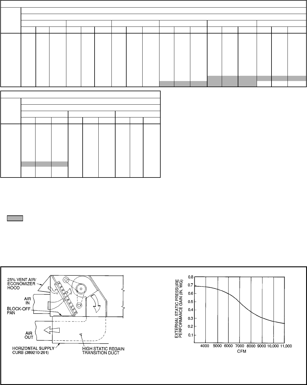
AIR DELIVERY — 559F180-300 UNITS (cont)
559F300 (25 TON)
Airflow
(Cfm)
Standard Belt-Drive Motor
External Static Pressure (in. wg)
0.2 0.4 0.6 0.8 1.0 1.2
Rpm Bhp Watts Rpm Bhp Watts Rpm Bhp Watts Rpm Bhp Watts Rpm Bhp Watts Rpm Bhp Watts
7,000 832 2.49 2297 916 2.86 2634 993 3.23 2978 1065 3.62 3332 1134 4.01 3,697 1200 4.43 4,076
7,500 881 3.00 2761 961 3.39 3119 1035 3.78 3483 1104 4.19 3855 1170 4.60 4,237 1233 5.03 4,631
8,000 930 3.57 3284 1007 3.98 3664 1077 4.40 4049 1144 4.82 4440 1207 5.25 4,840 1268 5.70 5,249
8,500 980 4.20 3873 1053 4.64 4274 1121 5.08 4679 1185 5.53 5090 1246 5.98 5,508 1305 6.44 5,934
9,000 1030 4.92 4528 1100 5.38 4951 1166 5.84 5377 1228 6.31 5808 1286 6.78 6,244 1343 7.26 6,689
9,500 1081 5.70 5254 1148 6.19 5700 1211 6.67 6146 1271 7.16 6597 1328 7.66 7,053 1383 8.16 7,515
10,000 1132 6.57 6055 1197 7.08 6523 1257 7.59 6991 1315 8.10 7462 1370 8.62 7,937 1423 9.14 8,418
10,500 1183 7.53 6935 1245 8.06 7425 1304 8.59 7913 1360 9.13 8404 1413 9.66 8,899 1465 10.20 9,400
11,000 1235 8.57 7896 1295 9.13 8408 1351 9.68 8918 1405 10.24 9430 1457 10.80 9,944 1507 11.36 10,465
11,250 1261 9.13 8408 1320 9.70 8932 1375 10.26 9452 1428 10.83 9974 1479 11.40 10,499 — — —
559F300 (25 TON) (cont)
Airflow
(Cfm)
Standard Belt-Drive Motor
External Static Pressure (in. wg)
1.4 1.6 1.8
Rpm Bhp Watts Rpm Bhp Watts Rpm Bhp Watts
7,000 1263 4.85 4470 1326 5.30 4880 1386 5.76 5307
7,500 1294 5.47 5038 1353 5.93 5458 1411 6.40 5893
8,000 1327 6.16 5670 1384 6.63 6102 1440 7.11 6549
8,500 1362 6.92 6371 1416 7.40 6816 1470 7.90 7215
9,000 1398 7.75 7141 1451 8.25 7602 1503 8.77 8074
9,500 1436 8.67 7985 1487 9.19 8462 — — —
10,000 1475 9.67 8905 1525 10.20 9400 — — —
10,500 1515 10.76 9907 — — — — — —
11,000 —— ——— ————
11,250 —— ——— ————
LEGEND
Bhp — Brake Horsepower Input to Fan
FIOP — Factory-Installed Option
Watts — Watts Input to Motor
NOTES:
1. Boldface indicates field-supplied drive is required. (See Note 3.)
2. indicates additional capability of 460-v motor.
3. Factory-shipped motor drive range is 1323 to 1579 rpm. Other rpms
require a field-supplied drive.
4. Maximum continuous bhp is 10.26 (208/230, 575 v) or 11.80 (460 v)
and maximum continuous watts are 9510 (208/230, 575 v) or
11,000 (460 v). Do not adjust motor rpm such that motor maximum
bhp and/or watts is exceeded at the maximum operating cfm.
5. Static pressure losses (i.e., economizer) must be added to external
static pressure before entering Air Delivery table.
6. Interpolation is permissible. Do not extrapolate.
7. Fan performance is based on wet coils, clean filters, and
casing losses. See page 47 for accessory/FIOP static pressure
information.
8. Extensive motor and drive testing on these units ensures that the
full horsepower and watts range of the motor can be utilized with
confidence. Using your fan motors up to the watts or bhp rating
shown will not result in nuisance tripping or premature motor failure.
Unit warranty will not be affected.
9. Minimum allowable cfm is 280 cfm/ton in cooling.
10. Use of a field-supplied motor may affect wire sizing. Contact your
local representative for details. For additional information on motor
performance, refer to Evaporator-Fan Motor Performance table on
page 62.
NOTE: The 389210-201 high static regain adapter accessory may
be used to provide horizontal supply/return.
NOTE: The 389210-201 horizontal supply/return adapter accessory
improves 559F180-300 fan performance by increasing external
static pressure by amount shown above.
559F180-300 Horizontal Supply/Return Fan Performance
With 389210-201 High Static Regain Adapter Curb
46
ACCESSORY/FIOP STATIC PRESSURE* (in. wg) — 558D036-072
COMPONENT CFM
900 1200 1400 1600 1800 2000 2200 2400 2600 3000
1 Heater Module 0.05 0.07 0.09 0.09 0.10 0.11 0.11 0.12 0.13 0.15
2 Heater Modules 0.15 0.16 0.16 0.16 0.17 0.17 0.17 0.18 0.18 0.19
Durablade Economizer 0.05 0.05 0.05 0.05 0.05 0.05 0.05 0.05 0.05 0.05
Parablade Economizer 0.08 0.10 0.17 0.26 0.33 0.34 0.36 0.40 0.44 −
LEGEND
FIOP — Factory-Installed Option
*The static pressure must be added to external static pressure. The sum
and the evaporator entering-air cfm should then be used in conjunction
with the Air Delivery tables to determine blower rpm and watts.
ACCESSORY/FIOP STATIC PRESSURE* (in. wg) — 558D090-150
COMPONENT CFM
2250 2500 3000 3500 4000 4500 5000 5500 6000 6250
1 Heater Module 0.02 0.03 0.05 0.07 0.08 0.10 0.12 0.14 0.16 0.17
2 Heater Modules 0.03 0.05 0.07 0.09 0.12 0.14 0.16 0.19 0.21 0.20
Durablade Economizer 0.02 0.02 0.03 0.04 0.05 0.06 0.07 0.08 0.09 0.09
Parablade Economizer 0.22 0.25 0.35 0.49 0.61 −−−−−
LEGEND
FIOP — Factory-Installed Option
*The static pressure must be added to external static pressure. The sum
and the evaporator entering-air cfm should then be used in conjunction
with the Air Delivery tables to determine blower rpm and watts.
ACCESSORY/FIOP STATIC PRESSURE* (in. wg) —
559F180
COMPONENT CFM
4500 5000 6000 7200 7500
Economizer 0.04 0.05 0.07 0.09 0.10
Electric Heat (kW)
26/34 0.06 0.07 0.09 0.11 0.12
32 0.06 0.07 0.09 0.11 0.12
42/56 0.07 0.08 0.12 0.16 0.17
50 0.09 0.10 0.15 0.20 0.21
55 0.07 0.08 0.12 0.15 0.17
56/75 0.09 0.10 0.15 0.20 0.21
80 0.09 0.10 0.15 0.20 0.21
LEGEND
FIOP — Factory-Installed Option
*The static pressure must be added to external static pressure. The sum
and the evaporator entering-air cfm should then be used in conjunction
with the Air Delivery tables to determine blower rpm and watts.
ACCESSORY/FIOP STATIC PRESSURE* (in. wg) —
559F216-300
COMPONENT CFM
5400 6000 7200 9000 10,000 11,250
Economizer 0.06 0.07 0.09 0.11 0.12 0.14
Electric Heat (kW)
26/34 0.08 0.09 0.11 0.15 0.17 0.20
32 0.08 0.09 0.11 0.15 0.17 0.20
42/56 0.11 0.12 0.15 0.19 0.21 0.24
55 0.11 0.12 0.15 0.19 0.21 0.24
56/75 0.14 0.15 0.20 0.24 0.26 0.29
80 0.14 0.15 0.20 0.24 0.26 0.29
LEGEND
FIOP — Factory-Installed Option
*The static pressure must be added to external static pressure. The sum
and the evaporator entering-air cfm should then be used in conjunction
with the Air Delivery tables to determine blower rpm and watts.
47
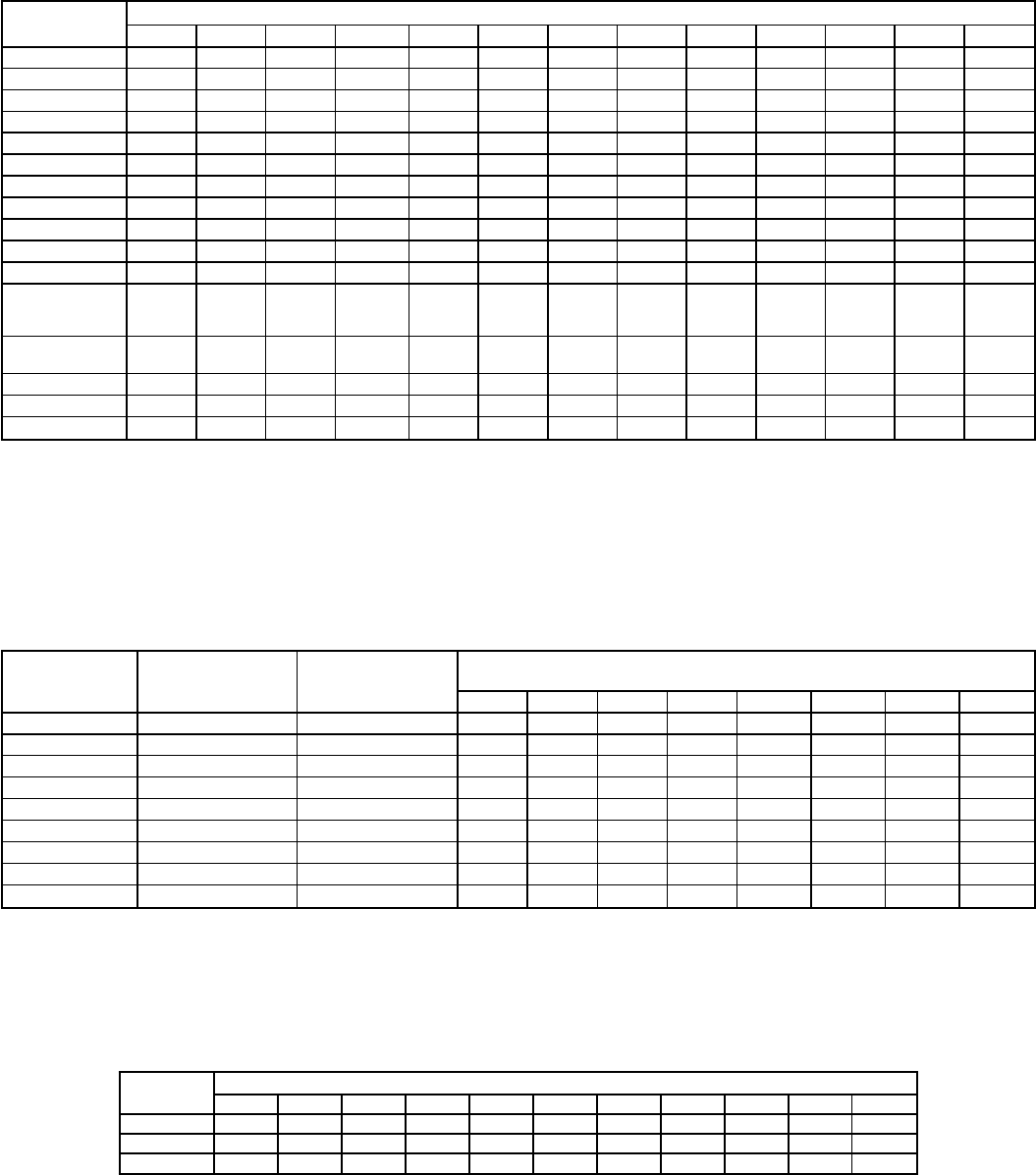
FAN RPM AT MOTOR PULLEY SETTINGS*
UNIT MOTOR PULLEY TURNS OPEN
0
1
⁄
2
11
1
⁄
2
22
1
⁄
2
33
1
⁄
2
44
1
⁄
2
55
1
⁄
2
6
558D036† 1000 976 952 928 904 880 856 832 808 784 760 — —
558D048† 1185 1150 1115 1080 1045 1010 975 940 905 870 835 — —
558D060† 1300 1260 1220 1180 1140 1100 1060 1020 980 940 900 — —
558D072** 1460 1420 1380 1345 1305 1265 1225 1185 1150 1110 1070 — —
558D090** 840 815 790 765 740 715 690 665 635 615 590 — —
558D090†† 935 910 885 860 835 810 785 760 735 710 685 — —
558D102** 935 910 885 860 835 810 785 760 735 710 685 — —
558D120** 935 910 885 860 835 810 785 760 735 710 685 — —
558D120† 1085 1060 1035 1010 985 960 935 910 885 860 835 — —
558D150** 1080 1060 1035 1015 990 970 950 925 905 880 860 — —
558D150† 1260 1220 1185 1155 1130 1100 1075 1045 1015 990 960 930 900
559F180,
208/230,
460 V** 1559 1524 1491 1458 1425 1392 1359 1326 1293 1260 1227 — —
559F180,
575 V** 1462 1436 1410 1384 1358 1332 1305 1279 1253 1227 1201 — —
559F216** 1251 1234 1217 1200 1183 1166 1149 1132 1115 1098 1081 1064 1047
559F240** 1494 1473 1451 1430 1409 1387 1366 1345 1323 1302 1281 1259 1238
559F300** \\1536 1515 1494 1472 1451 1430 1408 1387 1366 1344 1323
*Approximate fan rpm shown.
†Indicates alternate motor and drive package.
**Indicates standard motor and drive package.
††Indicates alternate drive package only.
\Do not run this fan at less than 1 full turn open, as it will exceed the maximum allowable rpm of 1550.
OUTDOOR SOUND DATA (Total Unit)
UNIT SOUND RATING
(Bels) A — WEIGHTED
(db)
SOUND POWER (db)
Octave Bands
63 125 250 500 1000 2000 4000 8000
558D036-060 8.2 80.5 56.8 75.8 72.4 72.9 74.8 75.4 71.3 69.1
558D072 8.4 82.4 56.0 69.8 72.9 75.9 78.3 76.5 72.6 67.9
558D090,102 8.6 86.4 83.2 87.4 83.5 82.8 83.0 77.7 71.8 67.0
558D120 8.8 87.6 97.6 90.4 85.7 84.8 83.9 77.5 71.3 65.8
558D150 8.8 86.4 83.7 87.2 83.4 82.8 83.0 77.7 71.8 67.0
559F180 8.8 87.3 87.1 89.9 86.4 84.0 82.7 79.0 73.9 68.6
559F216 9.0 89.5 95.7 88.9 87.2 85.2 81.9 79.5 72.7 65.0
559F240 9.5 94.1 98.7 92.3 93.8 90.9 89.6 85.9 80.3 74.3
559F300 9.5 94.1 98.7 92.3 93.8 90.9 89.6 85.9 80.3 74.3
Bels — Sound Levels (1 bel = 10 decibels)
db — Decibels
ELECTRIC HEAT MULTIPLICATION FACTORS
HEATER
VOLTAGE ACTUAL HEATER VOLTAGE
200 208 230 240 280 440 460 480 550 575 600
240 0.694 0.751 0.918 1.000 ———————
480 ————0.626 0.840 0.918 1.000 — — —
575 ————————0.915 1.000 1.089
NOTE: The following equation converts kW of heat energy to Btuh:
kW × 3.412 = Btuh. EXAMPLE: 32.0 kW (at 240 v) heater on 208 v = 32.0 (.751 mult factor)
= 24.0 kW capacity at 208 v.
48
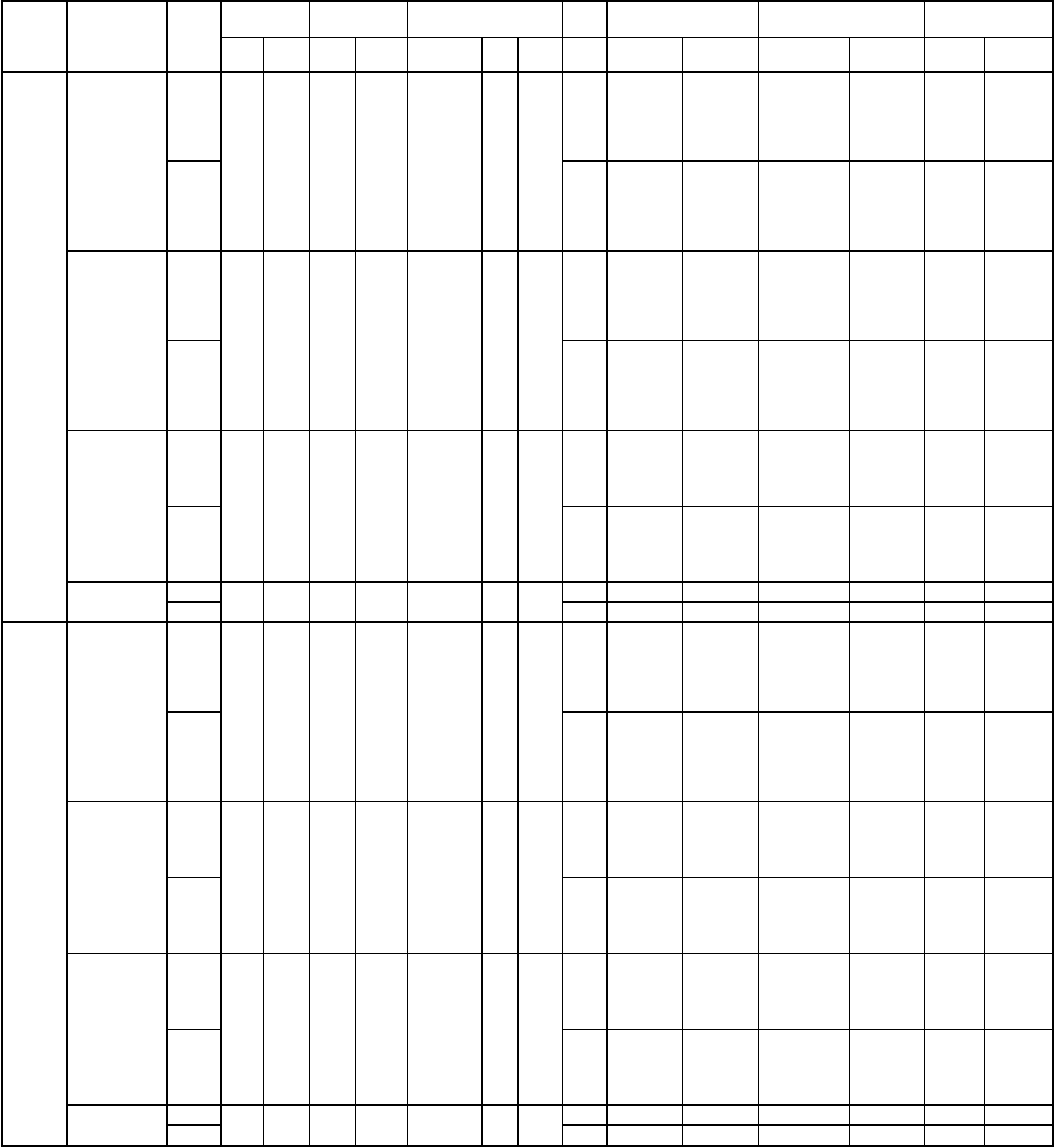
ELECTRICAL DATA — 558D036-072
UNIT
558D NOMINAL
V-PH-Hz IFM
TYPE
VOLTAGE
RANGE COMPR
(each) OFM IFM ELECTRIC
HEAT* POWER SUPPLY DISCONNECT
SIZE†
Min Max RLA LRA Quantity Hp FLA FLA Nominal
kW** FLA MCA MOCP†† FLA LRA
036
(3 Ton)
208/230-1-60
Std
187 254 16.9 86.7 1
1
⁄
4
1.4
2.8
— — 25.3/ 25.3 35/ 35 24/ 24
97/ 97
3.3/ 4.4 15.9/18.3 25.3/ 26.4 35/ 35 24/ 24
4.9/ 6.5 23.8/27.3 32.8/ 37.4 35/ 40 30/ 34
6.5/ 8.7 31.4/36.2 42.8/ 48.8 45/ 50 39/ 45
7.9/10.5 37.9/43.8 50.9/ 58.2 60/ 60 47/ 54
9.8/13.0 47.1/54.6 62.2/ 71.2 70/ 80\57/ 66
Alt 4.9
— — 27.4/ 27.4 35/ 35 27/ 27
102/102
3.3/ 4.4 15.9/18.3 27.4/ 27.4 35/ 35 27/ 27
4.9/ 6.5 23.5/27.1 35.5/ 40.0 40/ 40 33/ 37
6.5/ 8.7 31.4/36.3 45.4/ 51.4 50/ 60 42/ 47
7.9/10.5 37.9/43.8 53.5/ 60.8 60/ 70\49/ 56
9.8/13.0 46.9/54.2 64.8/ 73.8 70/ 80\60/ 68
208/230-3-60
Std
187 254 11.7 65.0 1
1
⁄
4
1.4
2.8
— — 18.8/ 18.8 25/ 25 18/ 18
76/ 76
3.3/ 4.4 9.2/10.6 18.8/ 18.8 25/ 25 18/ 18
4.9/ 6.5 13.6/15.6 20.4/ 23.0 25/ 25 19/ 21
6.5/ 8.7 18.1/20.9 26.2/ 29.7 30/ 35 24/ 27
7.9/10.5 21.9/25.3 30.9/ 35.1 35/ 40 28/ 32
12.1/16.0 33.5/38.6 45.3/ 51.7 50/ 60 42/ 48
Alt 4.9
— — 20.9/ 20.9 25/ 25 21/ 21
80/ 80
3.3/ 4.4 9.2/10.6 20.9/ 20.9 25/ 25 21/ 21
4.9/ 6.5 13.6/15.6 23.1/ 25.7 25/ 25 21/ 24
6.5/ 8.7 18.1/20.9 28.8/ 32.3 30/ 35 26/ 30
7.9/10.5 21.9/25.3 33.5/ 37.7 35/ 40 31/ 35
12.1/16.0 33.5/38.6 47.9/ 54.4 50/ 60 44/ 50
460-3-60
Std
414 508 5.1 33.0 1
1
⁄
4
0.8
1.3
— — 8.5 15 8
38
6.0 7.2 10.6 15 10
8.8 10.6 14.9 20 14
11.5 13.8 18.9 20 17
14.0 16.8 22.7 25 21
Alt 2.1
— — 9.3 15 9
41
6.0 7.2 11.6 15 10
8.8 10.6 15.9 20 15
11.5 13.8 19.9 20 18
14.0 16.8 23.7 25 22
575-3-60 Std 518 632 4.1 27.0 1
1
⁄
4
0.8 1.3 — — 6.8 15 7 31
Alt 2.1 — — 7.4 15 7 34
048
(4 Ton)
208/230-1-60
Std
187 254 23.0 110 1
1
⁄
4
1.4
3.5
— — 33.7/ 33.7 40/ 40 32/ 32
122/122
3.3/ 4.4 15.9/18.3 33.7/ 33.7 40/ 40 32/ 32
6.5/ 8.7 31.4/36.3 43.6/ 49.7 45/ 50 40/ 46
9.8/13.0 46.9/54.2 63.0/ 72.1 70/ 80\58/ 66
13.1/17.4 62.8/72.5 82.9/ 95.0 90/100\76/ 87
15.8/21.0 75.8/87.5 99.2/113.8 100/125\91/105
Alt 4.9
— — 35.1/ 35.1 45/ 45 34/ 34
125/125
3.3/ 4.4 15.9/18.3 35.1/ 35.1 45/ 45 34/ 34
6.5/ 8.7 31.4/36.3 45.4/ 51.4 50/ 60 42/ 47
9.8/13.0 46.9/54.2 64.8/ 73.8 70/ 80\60/ 68
13.0/17.4 62.8/72.5 84.7/ 96.8 90/100\78/ 89
15.9/21.0 75.8/87.5 100.9/115.5 100/125\93/106
208/230-3-60
Std
187 254 15.3 92.0 1
1
⁄
4
1.4
3.5
— — 24.0/ 24.0 30/ 30 24/ 24
116/116
4.9/ 6.5 13.6/15.6 24.0/ 24.0 30/ 30 24/ 24
6.5/ 8.7 18.1/20.9 27.0/ 30.5 30/ 35 27/ 30
12.0/16.0 33.4/38.5 46.1/ 52.5 50/ 60 45/ 51
15.8/21.0 43.8/50.5 59.1/ 67.5 60/ 70\58/ 64
Alt 4.9
— — 25.4/ 25.4 30/ 30 25/ 25
107/107
4.9/ 6.5 13.6/15.6 25.4/ 25.7 30/ 30 25/ 25
6.5/ 8.7 18.1/20.9 28.8/ 32.3 30/ 35 26/ 30
12.0/16.0 33.4/38.5 47.8/ 54.2 50/ 60 44/ 50
15.8/21.0 43.8/50.5 60.8/ 69.3 60/ 70\56/ 64
460-3-60
Std
414 508 7.0 46.0 1
1
⁄
4
0.8
1.8
— — 11.4 15 11
52
6.0 7.2 11.4 15 11
11.5 13.8 19.5 20 18
14.0 16.6 23.0 25 21
23.0 27.7 36.8 40 34
Alt 2.1
— — 11.7 15 11
54
6.0 7.2 11.7 15 11
11.5 14.0 19.9 20 18
14.0 16.6 23.4 25 22
23.0 27.7 37.2 40 34
575-3-60 Std 518 632 5.8 44.0 1
1
⁄
4
0.8 1.8 — — 9.3 15 9 49
Alt 2.1 — — 9.6 15 9 51
49
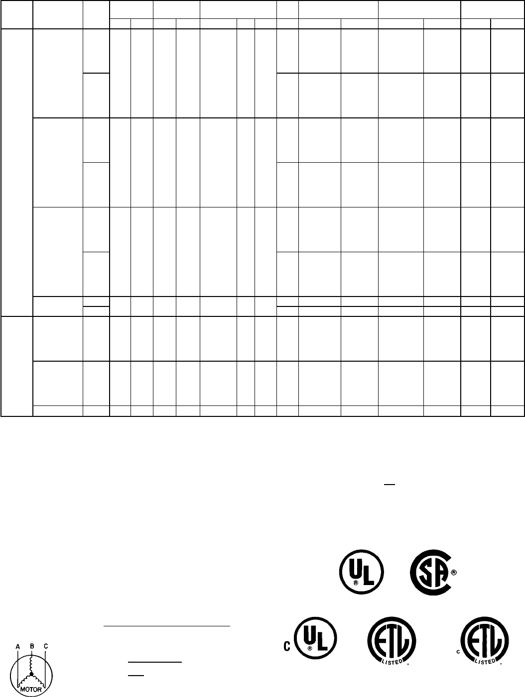
ELECTRICAL DATA — 558D036-072 (cont)
UNIT
558D NOMINAL
V-PH-Hz IFM
TYPE
VOLTAGE
RANGE COMPR
(each) OFM IFM ELECTRIC
HEAT* POWER SUPPLY DISCONNECT
SIZE†
Min Max RLA LRA Quantity Hp FLA FLA Nom kW** FLA MCA MOCP†† FLA LRA
060
(5 Ton)
208/230-1-60
Std
187 254 28.3 141 1
1
⁄
4
1.4
5.9
— — 42.7/ 42.7 50/ 50 43/ 43
155/155
4.9/ 6.5 23.5/27.1 42.7/ 42.7 50/ 50 43/ 43
6.5/ 8.7 31.4/36.3 46.6/ 52.7 50/ 60 46/ 49
9.8/13.0 46.9/54.2 66.0/ 75.1 70/ 80\64/ 69
13.0/17.4 62.8/72.5 85.9/ 98.0 90/100\82/ 90
15.8/21.0 75.8/87.5 102.2/116.8 110/125\97/107
Alt 8.5
— — 48.3/ 48.3 60/ 60 47/ 47
178/178
4.9/ 6.5 23.5/27.1 48.3/ 48.3 60/ 60 47/ 47
6.5/ 8.7 31.4/36.3 50.3/ 56.3 60/ 60 47/ 52
9.8/13.0 46.9/54.2 69.7/ 78.7 70/ 80\64/ 72
13.0/17.4 62.8/72.5 89.5/101.6 90/110\82/ 93
15.8/21.0 75.8/87.5 105.8/120.4 110/125\97/111
208/230-3-60
Std
187 254 17.7 110 1
1
⁄
4
1.4
5.9
— — 29.4/ 29.4 35/ 35 29/ 29
124/124
4.9/ 6.5 13.6/15.6 29.4/ 29.4 35/ 35 29/ 29
7.9/10.5 21.9/25.3 34.7/ 38.9 40/ 40 32/ 36
12.0/16.0 33.4/38.5 49.1/ 55.5 50/ 60 46/ 51
15.8/21.0 43.8/50.5 62.1/ 70.5 70/ 80\57/ 65
19.9/26.5 55.2/63.8 76.4/ 87.1 80/ 90\70/ 80
Alt 8.5
— — 32.0/ 32.0 40/ 40 29/ 29
145/145
4.9/ 6.5 13.6/15.6 32.0/ 32.0 40/ 40 29/ 29
7.9/10.5 21.9/25.3 38.0/ 42.2 45/ 45 32/ 36
12.0/16.0 33.4/38.5 52.3/ 58.7 60/ 60 45/ 51
15.8/21.0 43.8/50.5 65.3/ 73.8 70/ 80\57/ 65
19.9/26.5 55.2/63.8 79.7/ 90.3 80/100\70/ 80
460-3-60
Std
414 508 8.6 55 1
1
⁄
4
0.8
3.2
— — 14.8 20 15
63
6.0 7.2 14.8 20 15
11.5 13.8 21.3 25 20
14.0 16.8 25.0 30 23
23.0 27.7 38.6 40 36
25.0 30.1 41.6 45 38
Alt 4.5
— — 16.1 20 14
73
6.0 7.2 16.1 20 14
11.5 13.8 22.9 25 19
14.0 16.8 26.7 30 22
23.0 27.7 40.2 45 35
25.0 30.1 43.2 45 38
575-3-60 Std 518 632 6.4 44 1
1
⁄
4
0.8 3.2 — — 12.0 15 12 52
Alt 2.6 — — 11.4 15 12 62
072
(6 Ton)
208/230-
3-60 Std 187 254 20.9 142 1
1
⁄
4
1.4 5.8
— — 33.3/ 33.3 40/ 40 32/ 32
187/187
4.9/ 6.5 13.6/15.6 33.3/ 33.3 40/ 40 32/ 32
7.9/10.5 21.9/25.3 33.3/ 38.8 40/ 40 32/ 36
12.0/16.0 33.4/38.4 48.9/ 55.4 50/ 60 45/ 51
15.8/21.0 43.8/50.5 62.0/ 70.4 70/ 80\57/ 65
19.9/26.5 55.2/63.8 76.8/ 86.9 80/ 90\70/ 80
460-3-60 Std 414 508 9.9 72 1
1
⁄
4
0.8 2.6
— — 15.6 20 15
94
6.0 7.2 15.6 20 15
11.5 13.8 20.5 25 19
14.0 16.8 24.3 25 22
23.0 27.8 37.8 40 35
25.5 30.7 41.6 45 38
575-3-60 Std 518 632 7.9 58 1
1
⁄
4
0.8 2.6 — — 14.6 15 12 76
LEGEND AND NOTES FOR ELECTRICAL DATA TABLES ON PAGES 49-54
LEGEND
FLA — Full Load Amps
HACR — Heating, Air Conditioning and Refrigeration
IFM — Indoor (Evaporator) Fan Motor
LRA — Locked Rotor Amps
MCA — Minimum Circuit Amps
MOCP — Maximum Overcurrent Protection
NEC — National Electrical Code
OFM — Outdoor (Condenser) Fan Motor
RLA — Rated Load Amps
*Heater capacity (kW) is based on heater voltage of 208 v, 240 v, 480 v, and
575 v. Heaters are rated at 240 v, 480 v, and 575 v. If power distribution voltage to unit
varies from rated heater voltage, heater kW will vary accordingly. To determine heater
capacity at actual unit voltage, multiply 240 v, 480 v, or 575 v capacity by multipliers
found in Electric Heat Multiplication Factors table on page 48.
†Used to determine minimum disconnect size per NEC.
**Heaters are field installed only.
††Fuse or HACR circuit breaker.
\Fusing in single point box provides the required branch circuit protection.
NOTES:
1. In compliance with NEC requirements for multimotor and combination load equipment
(refer to NEC Articles 430 and 440), the overcurrent protective device for the unit shall
be fuse or HACR breaker. The Canadian units may be fuse or circuit breaker.
2. Unbalanced 3-Phase Supply Voltage
Never operate a motor where a phase imbalance in supply voltage is greater than
2%.
Use the following formula to determine the percent of voltage imbalance.
max voltage deviation from average voltage
% Voltage Imbalance =100 x average voltage
EXAMPLE: Supply voltage is 460-3-60.
AB = 452 v
BC = 464 v
AC = 455 v 452 + 464 + 455
Average Voltage = 3
1371
=3
= 457
Determine maximum deviation from average voltage.
(AB) 457 − 452 = 5 v
(BC) 464 − 457=7v
(AC) 457 − 455=2v
Maximum deviation is 7 v.
Determine percent of voltage imbalance.
7
% Voltage Imbalance = 100 x 457
= 1.53%
This amount of phase imbalance is satisfactory as it is below the maximum
allowable 2%.
IMPORTANT: If the supply voltage phase imbalance is more than 2%, contact your
local electric utility company immediately.
3. MCA calculation for 558F180-300 units with electric heaters over 50 kW =
(1.25 x IFM amps) + (1.00 x heater FLA).
036-150 Only 036-072 Only
090-150 Only 180-300 Only 180-300 Only
50

ELECTRICAL DATA — 558D090-150
UNIT
558D NOMINAL
V-PH-Hz IFM VOLTAGE
RANGE COMPR
(ea) OFM
(ea) IFM ELECTRIC
HEAT* POWER SUPPLY DISCONNECT
SIZE†
Min Max RLA LRA Qty Hp FLA FLA Nom kW** FLA MCA MOCP†† FLA LRA
090
(7
1
⁄
2
Tons)
208/230-3-60 Std 187 254 13.6 73.4 2
1
⁄
4
1.4 5.8
— — 39.2/ 39.2 45/ 45 41/ 41
194/194
7.8/10.4 21.7/ 25.0 39.2/ 39.2 45/ 45 41/ 41
12.0/16.0 33.4/ 38.5 48.9/ 55.4 50/ 60 45/ 51
18.6/24.8 51.7/ 59.7 71.9/ 81.8 80/ 90\66/ 75
24.0/32.0 66.7/ 74.2 90.6/103.5 100/110\83/ 95
31.9/42.4 88.4/102.0 117.8/134.8 125/150\108/124
460-3-60 Std 414 508 6.2 37.7 2
1
⁄
4
0.7 2.6
— — 18.0 25 19
99
13.9 16.7 24.1 25 22
16.5 19.8 28.1 30 26
27.8 33.4 45.0 50 41
33.0 39.7 52.9 60 49
41.7 50.2 65.9 70\61
575-3-60 Std 518 632 4.9 31.0 2
1
⁄
4
0.7 2.6 — — 14.2 20 15 8118.0 17.0 23.9 25 23
36.0 34.0 45.3 50 42
102
(8
1
⁄
2
Tons)
208/230-3-60 Std 187 254 15.8 92.0 2
1
⁄
4
1.4 5.8
— — 44.2/ 44.2 50/ 50 46/ 46
231/231
7.8/10.4 21.7/ 25.0 44.2/ 44.2 50/ 50 46/ 46
12.0/16.0 33.4/ 38.5 48.9/ 55.4 50/ 60 46/ 51
18.6/24.8 51.7/ 59.7 71.9/ 81.8 80/ 90\66/ 75
24.0/32.0 66.7/ 77.0 90.6/103.5 100/110\83/ 95
31.8/42.4 88.4/102.0 117.7/134.8 125/150\108/124
460-3-60 Std 414 508 7.4 46.0 2
1
⁄
4
0.7 2.6
— — 20.7 25 22
116
13.9 16.7 24.1 25 22
16.5 19.8 28.1 30 26
27.8 33.4 45.0 50 41
33.0 39.7 52.9 60 49
41.7 50.2 65.9 70\61
575-3-60 Std 518 632 5.9 44.0 2
1
⁄
4
0.7 2.6 — — 16.5 20 17 10718.0 17.0 23.9 25 23
36.0 34.0 45.3 50 42
120
(10 Tons)
208/230-3-60
Std
187 254 17.9 110 2
1
⁄
4
1.4
5.8
— — 48.9/ 48.9 60/ 60 51/ 51
267/267
7.8/10.4 21.7/ 25.0 48.9/ 48.9 60/ 60 51/ 51
12.0/16.0 33.4/ 38.5 48.9/ 55.4 60/ 60 51/ 51
24.0/32.0 66.7/ 77.0 90.6/103.5 100/110\83/ 95
31.8/42.4 88.4/102.0 117.7/134.8 125/150\108/124
37.5/50.0 104.2/120.3 137.5/127.5 150/150\127/145
Alt 7.5
— — 50.6/ 50.6 60/ 60 53/ 53
286/286
7.8/10.4 21.7/ 25.0 50.6/ 50.6 60/ 60 53/ 53
12.0/16.0 33.4/ 38.5 51.1/ 57.5 60/ 60 53/ 53
24.0/32.0 66.7/ 77.0 92.8/105.6 100/110\85/ 97
31.8/42.4 88.4/102.0 119.9/136.9 125/150\110/126
37.5/50.0 104.2/120.3 139.7/129.7 150/150\129/147
460-3-60
Std
414 508 8.6 55.0 2
1
⁄
4
0.7
2.6
— — 23.4 30 24
134
16.5 19.8 28.1 30 26
27.8 33.4 45.0 50 41
33.0 39.7 52.9 60 49
41.7 50.2 65.9 70\61
50.0 60.1 63.4 70\72
Alt 3.4
— — 24.2 30 25
173
16.5 19.8 29.1 30 27
27.8 33.4 46.0 50 42
33.0 39.7 53.9 60 50
41.7 50.2 66.9 70\62
50.0 60.1 64.4 70\73
575-3-60
Std
518 632 6.4 44.0 2
1
⁄
4
0.7
2.6
— — 17.6 20 18
107
18.0 17.0 23.8 25 22
36.0 34.0 45.1 50 42
54.0 51.0 53.6 60 61
Alt 3.4
— — 18.2 20 19
139
18.0 17.0 24.6 25 23
36.0 34.0 45.9 50 42
54.0 51.0 54.4 60 62
51
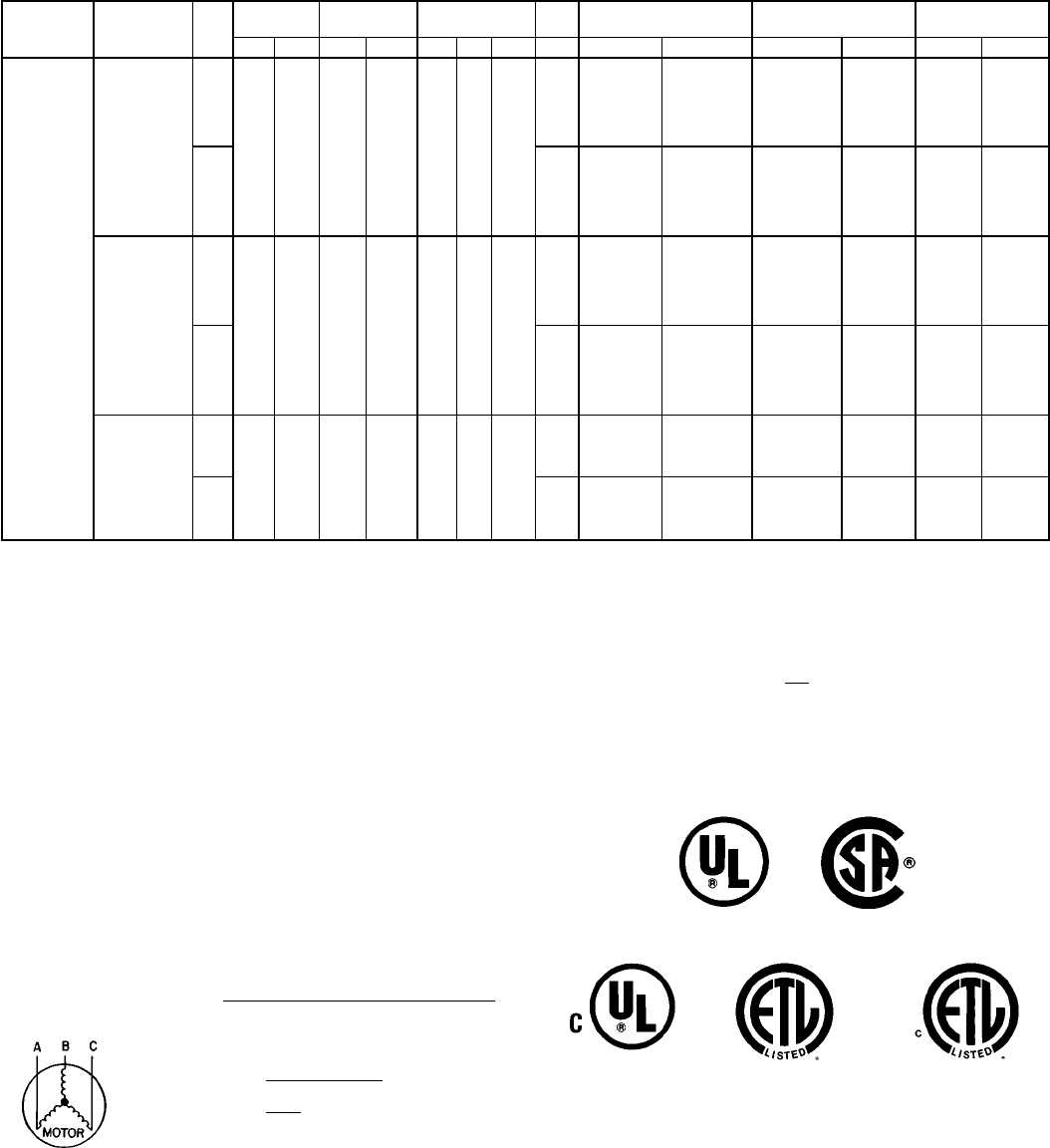
ELECTRICAL DATA — 558D090-150 (cont)
UNIT
558D NOMINAL
V-PH-Hz IFM VOLTAGE
RANGE COMPR
(ea) OFM IFM ELECTRIC
HEAT* POWER SUPPLY DISCONNECT
SIZE†
Min Max RLA LRA Qty Hp FLA FLA Nom kW** FLA MCA MOCP†† FLA LRA
150
(12
1
⁄
2
Tons)
208/230-3-60
Std
187 254 22.3 142.0 2
1
⁄
4
1.4
10.6
— — 63.6/ 63.6 70/ 70\67/ 67
375/375
7.8/10.4 21.7/ 25.0 63.6/ 63.6 70/ 70\67/ 67
12.0/16.0 33.4/ 38.1 63.6/ 63.6 70/ 70\67/ 67
24.0/32.0 66.7/ 74.2 96.6/109.5 100/110\89/101
31.8/42.4 88.4/102.0 123.7/140.8 125/150\114/129
37.5/50.0 104.2/120.3 143.5/133.5 150/150\132/151
Alt 15.0
— — 68.0/ 68.0 80/ 80\72/ 72
398/398
7.8/10.4 21.7/ 25.0 68.0/ 68.0 80/ 80\72/ 72
12.0/16.0 33.4/ 38.1 68.0/ 68.0 80/ 80\72/ 72
24.0/32.0 66.7/ 74.2 102.1/115.0 110/125\94/106
31.8/42.4 88.4/102.0 129.2/146.3 150/150\119/135
37.5/50.0 104.2/120.3 149.0/139.0 150/175\137/156
460-3-60
Std
414 508 10.4 72.0 2
1
⁄
4
0.8
4.8
— — 29.6 40 31
190
16.5 19.8 30.8 40 31
27.8 33.4 47.8 50 44
33.0 39.7 55.6 60 51
41.7 50.2 68.7 70\63
50.0 60.1 66.1 80\75
Alt 7.4
— — 32.2 45 34
201
16.5 19.8 34.1 45 34
27.8 33.4 51.0 60 47
33.0 39.7 58.9 60 54
41.7 50.2 71.9 80\66
50.0 60.1 69.4 80\78
575-3-60
Std
518 632 9.6 58.5 2
1
⁄
4
0.8
4.8
— — 26.6 30 28
154
18.0 17.0 26.6 30 28
36.0 34.0 47.5 50 44
54.0 51.0 56.0 60 63
Alt 7.4
— — 28.6 35 30
162
18.0 17.0 28.7 35 30
36.0 34.0 50.1 50 46
54.0 51.0 58.6 70\66
LEGEND AND NOTES FOR ELECTRICAL DATA TABLES ON PAGES 49-54
LEGEND
FLA — Full Load Amps
HACR — Heating, Air Conditioning and Refrigeration
IFM — Indoor (Evaporator) Fan Motor
LRA — Locked Rotor Amps
MCA — Minimum Circuit Amps
MOCP — Maximum Overcurrent Protection
NEC — National Electrical Code
OFM — Outdoor (Condenser) Fan Motor
RLA — Rated Load Amps
*Heater capacity (kW) is based on heater voltage of 208 v, 240 v, 480 v, and
575 v. Heaters are rated at 240 v, 480 v, and 575 v. If power distribution voltage
to unit varies from rated heater voltage, heater kW will vary accordingly. To de-
termine heater capacity at actual unit voltage, multiply 240 v, 480 v, or 575 v
capacity by multipliers found in Electric Heat Multiplication Factors table on
page 48.
†Used to determine minimum disconnect size per NEC.
**Heaters are field installed only.
††Fuse or HACR circuit breaker.
\Fusing in single point box provides the required branch circuit protection.
NOTES:
1. In compliance with NEC requirements for multimotor and combination load
equipment (refer to NEC Articles 430 and 440), the overcurrent protective de-
vice for the unit shall be fuse or HACR breaker. The Canadian units may be
fuse or circuit breaker.
2. Unbalanced 3-Phase Supply Voltage
Never operate a motor where a phase imbalance in supply voltage is greater
than 2%.
Use the following formula to determine the percent of voltage
imbalance. max voltage deviation from average voltage
% Voltage Imbalance = 100 x average voltage
EXAMPLE: Supply voltage is 460-3-60.
AB = 452 v
BC = 464 v
AC = 455 v 452 + 464 + 455
Average Voltage = 3
1371
=3
= 457
Determine maximum deviation from average voltage.
(AB) 457 − 452=5v
(BC) 464 − 457=7v
(AC) 457 − 455=2v
Maximum deviation is 7 v.
Determine percent of voltage imbalance.
7
% Voltage Imbalance = 100 x 457
= 1.53%
This amount of phase imbalance is satisfactory as it is below the maximum
allowable 2%.
IMPORTANT: If the supply voltage phase imbalance is more than 2%, contact
your local electric utility company immediately.
3. MCA calculation for units with electric heaters over 50 kW = (1.25 x IFM amps)
+ (1.00 x heater FLA).
036-150 Only 036-072 Only
090-150 Only 180-300 Only 180-300 Only
52

ELECTRICAL DATA — 559F180-300 UNITS
UNIT
559F NOMINAL
V-PH-Hz
VOLTAGE
RANGE COMPRESSOR OFM IFM POWER
EXHAUST ELECTRIC
HEAT* POWER
SUPPLY
No. 1 No. 2
Min Max RLA LRA RLA LRA Quantity Hp FLA
(ea) FLA FLA LRA FLA Nom kW** MCA MOCP††
180
208/230-3-60 187 254 61.0 266 — — 3
1
⁄
2
1.70 10.5/10.5
——
—/— —/— 92/ 92 150/150
72/ 82 26/34 103/116 150/150
117/135 42/56 159/148 175/150
156/180 56/75 169/193 175/200
4.6 18.8
—/— —/— 96/ 96 150/150
72/ 82 26/34 109/121 150/150
117/135 42/56 165/154 175/175
156/180 56/75 175/199 175/200
460-3-360 414 508 28.0 120 — — 3
1
⁄
2
0.80 4.8
——
— — 42 70
39 32 55 70
66 55 72 80
96 80 102 110
2.3 6.0
— — 45 70
39 32 58 70
66 55 75 80
96 80 105 110
575-3-60 518 632 23.0 96 — — 3
1
⁄
2
0.75 3.9 —— — — 35 50
50 50 58 60
2.1 4.8 — — 37 60
50 50 57 60
216
208/230-3-60 187 254 35.6 198 28.2 160 3
1
⁄
2
1.70 15.8/15.8
——
—/— —/— 94/ 94 125/125
72/ 82 26/34 110/122 125/125
117/135 42/56 166/155 175/175
156/180 56/75 176/200 200/200
4.6 18.8
—/— —/— 98/ 98 125/125
72/ 82 26/34 116/128 125/150
117/135 42/56 172/161 175/175
156/180 56/75 182/206 200/225
460-3-60 414 508 17.8 99 14.1 80 3
1
⁄
2
0.80 7.9
——
— — 47 60
39 32 59 60
66 55 76 80
96 80 106 110
2.3 6.0
— — 49 60
39 32 62 70
66 55 79 80
96 80 109 110
575-3-60 518 632 14.3 79 11.3 64 3
1
⁄
2
0.75 6.0 — — — — 37 50
2.1 4.8 — — 40 50
53

ELECTRICAL DATA — 559F180-300 UNITS (cont)
UNIT
559F NOMINAL
V-PH-Hz
VOLTAGE
RANGE COMPRESSOR OFM IFM POWER
EXHAUST ELECTRIC
HEAT* POWER
SUPPLY
No. 1 No. 2
Min Max RLA LRA RLA LRA Quantity Hp FLA
(ea) FLA FLA LRA FLA Nom kW** MCA MOCP††
240
208/230-3-60 187 254 35.6 198 35.6 198 2 1 5.50 25.0/25.0
——
—/— —/— 116/116 150/150
72/ 82 26/34 121/134 150/150
117/135 42/56 178/166 200/175
156/180 56/75 187/211 200/225
4.6 18.8
—/— —/— 121/121 150/150
72/ 82 26/34 127/140 150/150
117/135 42/56 183/172 200/175
156/180 56/75 193/217 200/225
460-3-60 414 508 17.8 99 17.8 99 2 1 2.80 13.0
——
— — 59 70
39 32 65 70
66 55 82 90
96 80 112 125
2.3 6.0
— — 61 70
39 32 68 70
66 55 85 90
96 80 115 125
575-3-60 518 632 14.3 79 14.3 79 2 1 3.40 10.0 — — — — 49 60
2.1 4.8 — — 51 60
300
208/230-3-60 187 254 43.6 228 43.6 228 2 1 5.50 28.0/28.0
——
—/— —/— 137/137 175/175
72/ 82 26/34 137/138 175/175
117/135 42/56 181/170 200/175
156/180 56/75 191/215 200/225
4.6 18.8
—/— —/— 142/142 175/175
72/82 26/34 142/143 175/175
117/135 42/56 187/176 200/200
156/180 56/75 197/221 200/225
460-3-60 414 508 22.1 114 22.1 114 2 1 2.80 14.6
——
— — 70 90
39 32 70 90
66 55 84 90
96 80 114 125
2.3 6.0
— — 72 90
39 32 72 90
66 55 87 90
96 80 117 125
575-3-60 518 632 17.9 91 17.9 91 2 1 3.40 13.0 — — — — 60 70
2.1 4.8 — — 62 80
LEGEND AND NOTES FOR ELECTRICAL DATA TABLES ON PAGES 49-54
LEGEND
FLA — Full Load Amps
HACR — Heating, Air Conditioning and Refrigeration
IFM — Indoor (Evaporator) Fan Motor
LRA — Locked Rotor Amps
MCA — Minimum Circuit Amps
MOCP — Maximum Overcurrent Protection
NEC — National Electrical Code
OFM — Outdoor (Condenser) Fan Motor
RLA — Rated Load Amps
*Heater capacity (kW) is based on heater voltage of 208 v, 240 v, 480 v, and
575 v. Heaters are rated at 240 v, 480 v, or 575 v. If power distribution voltage
to unit varies from rated heater voltage, heater kW will vary accordingly. To de-
termine heater capacity at actual unit voltage, multiply 240 v, 480 v, or 575 v
capacity by multipliers found in Electric Heat Multiplication Factors table on
page 48.
†Used to determine minimum disconnect size per NEC.
**Heaters are field installed only.
††Fuse or HACR circuit breaker.
\Fusing in single point box provides the required branch circuit protection.
NOTES:
1. In compliance with NEC requirements for multimotor and combination load
equipment (refer to NEC Articles 430 and 440), the overcurrent protective de-
vice for the unit shall be fuse or HACR breaker. The Canadian units may be
fuse or circuit breaker.
2. Unbalanced 3-Phase Supply Voltage
Never operate a motor where a phase imbalance in supply voltage is greater
than 2%.
Use the following formula to determine the percent of voltage
imbalance.
max voltage deviation from average voltage
% Voltage Imbalance = 100 x average voltage
EXAMPLE: Supply voltage is 460-3-60.
AB = 452 v
BC = 464 v
AC = 455 v 452 + 464 + 455
Average Voltage = 3
1371
=3
= 457
Determine maximum deviation from average voltage.
(AB) 457 − 452 = 5 v
(BC) 464 − 457 = 7 v
(AC) 457 − 455 = 2 v
Maximum deviation is 7 v.
Determine percent of voltage imbalance.
7
% Voltage Imbalance = 100 x 457
= 1.53%
This amount of phase imbalance is satisfactory as it is below the maximum
allowable 2%.
IMPORTANT: If the supply voltage phase imbalance is more than 2%, contact
your local electric utility company immediately.
3. MCA calculation for units with electric heaters over 50 kW = (1.25 x IFM amps)
+ (1.00 x heater FLA).
036-150 Only 036-072 Only
090-150 Only 180-300 Only 180-300 Only
54
OPERATING SEQUENCE
COOLING, UNITS WITHOUT ECONOMIZER — When thermo-
stat calls for cooling, terminals G and Y1 are energized. The in-
door (evaporator) fan contactor (IFC) and compressor contactor
no. 1 (C1) are energized and evaporator-fan motor, compressor
no. 1 (036-150 and 216-300) or unloaded compressor (180),
and condenser fan(s) start. The condenser-fan motor runs con-
tinuously while unit is cooling. On 090-300 units, if the thermo-
stat calls for a second stage of cooling by energizing Y2,
compressor contactor no. 2 (C2) is energized and compressor
no. 2 starts (090-150 and 216-300), or compressor no. 1 runs
fully loaded (180).
HEATING, UNITS WITHOUT ECONOMIZER (IF ACCESSORY
OR OPTIONAL HEATER IS INSTALLED) — Upon a call for
heating through terminal W1, IFC and heater contactor no. 1
(HC1) are energized. On units equipped for 2 stages of heat,
when additional heat is needed, HC2 is energized through W2.
COOLING, UNITS WITH DURABLADE ECONOMIZER (036-
150) — When the outdoor-air temperature is above the outdoor-
air thermostat (OAT) setting and the room thermostat calls for
cooling, compressor contactor no. 1 is energized to start com-
pressor no. 1 and the condenser-fan motor. The evaporator-fan
motor is energized and the economizer damper moves to the
minimum position. Upon a further call for cooling, compressor
contactor no. 2 will be energized, starting compressor no. 2. Af-
ter the thermostat is satisfied, the damper moves to the fully-
closed position.
When the outdoor-air temperature is below the OAT setting and
the thermostat calls for cooling, the economizer dampers move
to the minimum position. If the supply-air temperature is above
57 F, the damper continues to open until it reaches the fully-
openposition oruntil thesupply-airtemperature dropsbelow 57F.
When the supply-air temperature falls to between 57 F and 52 F,
the damper will remain at an intermediate open position. If the
supply-air temperature falls below 52 F, the damper will modu-
late closed until it reaches the minimum position or until the
supply-air temperature is above 52 F. When the thermostat is
satisfied, the damper will move to the fully-closed position.
If the outdoor air alone cannot satisfy the cooling requirements
of the conditioned space, economizer cooling is integrated with
mechanical cooling, providing second-stage cooling. Compres-
sor no. 1 and the condenser fan will be energized and the
position of the economizer damper will be determined by the
supply-air temperature. Compressor no. 2 is locked out.
When the second stage of cooling is satisfied, the compressor
and condenser-fan motor will be deenergized. The damper po-
sition will be determined by the supply-air temperature.
When the first stage of cooling is satisfied, the damper will move
to fully-closed position.
COOLING, UNITS WITH PARABLADE ECONOMIZER
(036-072) — When the outdoor air is above the enthalpy control
(EC) setting, and the room thermostat calls for cooling, the com-
pressor contactor is energized to start the compressor and the
condenser-fan motor. The evaporator-fan motor is energized
and the economizer damper moves to the minimum position. Af-
ter the room thermostat is satisfied, the damper will spring re-
turn to the fully-closed position.
When the outdoor-air is below the EC setting and the thermostat
calls for cooling, the economizer outdoor-air damper is opened
proportionally to maintain between 50 and 56 F at the mixed-air
sensor. If outdoor air alone cannot satisfy the cooling require-
ments, economizer cooling is integrated with mechanical cool-
ing. When the room thermostat is satisfied, the damper will
spring return to the fully-closed position.
COOLING, UNITS WITH PARABLADE ECONOMIZER
(090-150) — When the outdoor-air is above the enthalpy control
(EC) setting, and the room thermostat calls for cooling, com-
pressor contactor no. 1 is energized to start compressor
no. 1 and the condenser-fan motor. The evaporator-fan motor is
energized and the economizer damper moves to the minimum
position. Upon a further call for cooling, compressor contactor
no. 2 is energized, starting compressor no. 2. After the room
thermostat is satisfied, the damper will spring return to the fully-
closed position.
When the outdoor-air temperature is below the EC setting and
the thermostat calls for cooling, the economizer outdoor-air
damper is opened proportionally to maintain between 50 and
56 F at the mixed-air sensor. If outdoor-air alone cannot satisfy
the cooling requirements, economizer cooling is integrated with
mechanical cooling, and the second compressor is locked out.
When the room thermostat is satisfied, the damper will spring
return to the fully-closed position.
COOLING, UNITS WITH ECONOMIZER (180-300) — Upon a
call for cooling, when outdoor ambient temperature is above the
temperature control setting, the evaporator and condenser fans
and compressor energize. The economizer damper moves to
VENT position.
Upon a first-stage call for cooling, when outdoor ambient tem-
perature is below the temperature control setting, the evapora-
tor fan starts and economizer damper modulates to maintain
mixed-air temperature. The compressor(s) remains off.
Upon a second-stage call for cooling, compressor no. 1 (180-
300) or unloaded compressor (180) is energized and mechani-
cal cooling is integrated with economizer cooling. Compressor
no. 2 is locked out. If the air temperature is above 50 F, a cooling
lockout switch prevents the compressor(s) from running.
When supply-air temperature drops below a fixed set point, the
economizer damper modulates to maintain the temperature at
the fixed set point.
A freeze protection thermostat (FPT) is located on the evapora-
tor coil. It detects frost build-up and turns off the compressor, al-
lowing the coil to clear. Once frost has melted, the compressor
can be reenergized.
HEATING, UNITS WITH ECONOMIZER (036-150) (IF ACCES-
SORY OR OPTIONAL HEATER IS INSTALLED) — When the
room thermostat calls for heat through terminal W1, the
evaporator-fan contactor and heater contactor no. 1 are ener-
gized. On units equipped for 2 stages of heat, when additional
heat is needed, heater contactor no. 2 is energized through W2.
The economizer damper moves to the minimum position during
heating. When the thermostat is satisfied, the damper moves to
the fully closed position.
HEATING, UNITS WITH ECONOMIZER (180-300) (IF ACCES-
SORY OR OPTIONAL HEATER IS INSTALLED) — The
outdoor-air damper stays at VENT position while the evaporator
fan is operating. Refer to Heating, Units Without Economizer
section, above, for remainder of operating sequence.
55
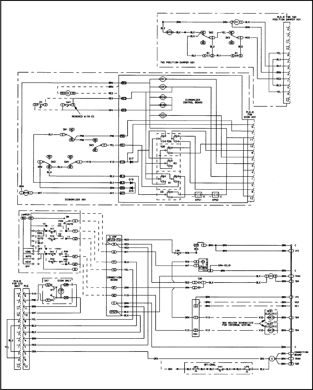
TYPICAL WIRING SCHEMATIC — 558D036-150
(See Legend, page 59.)
56
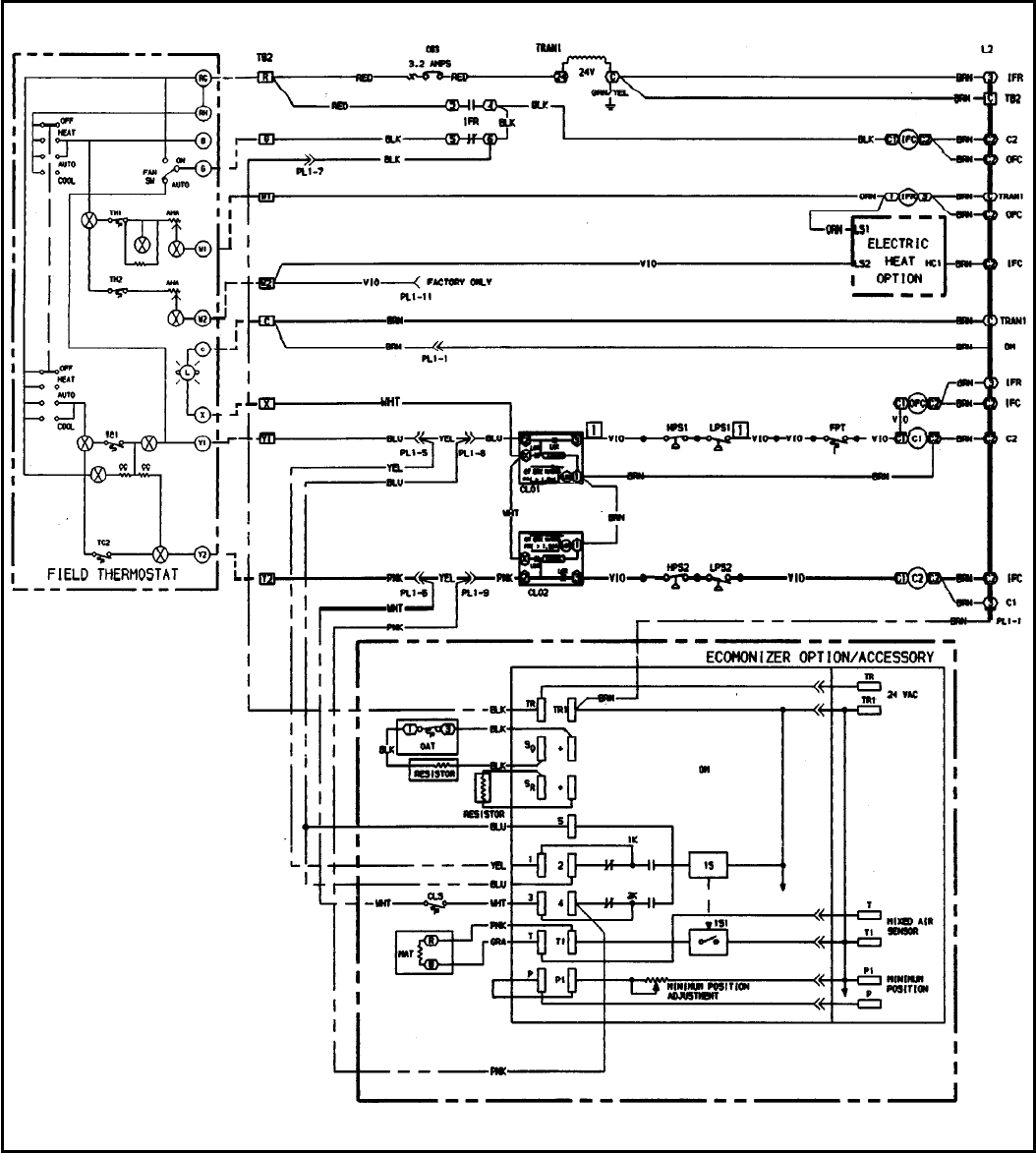
TYPICAL WIRING SCHEMATIC — 559F180-300
(See Legend, page 59.)
57
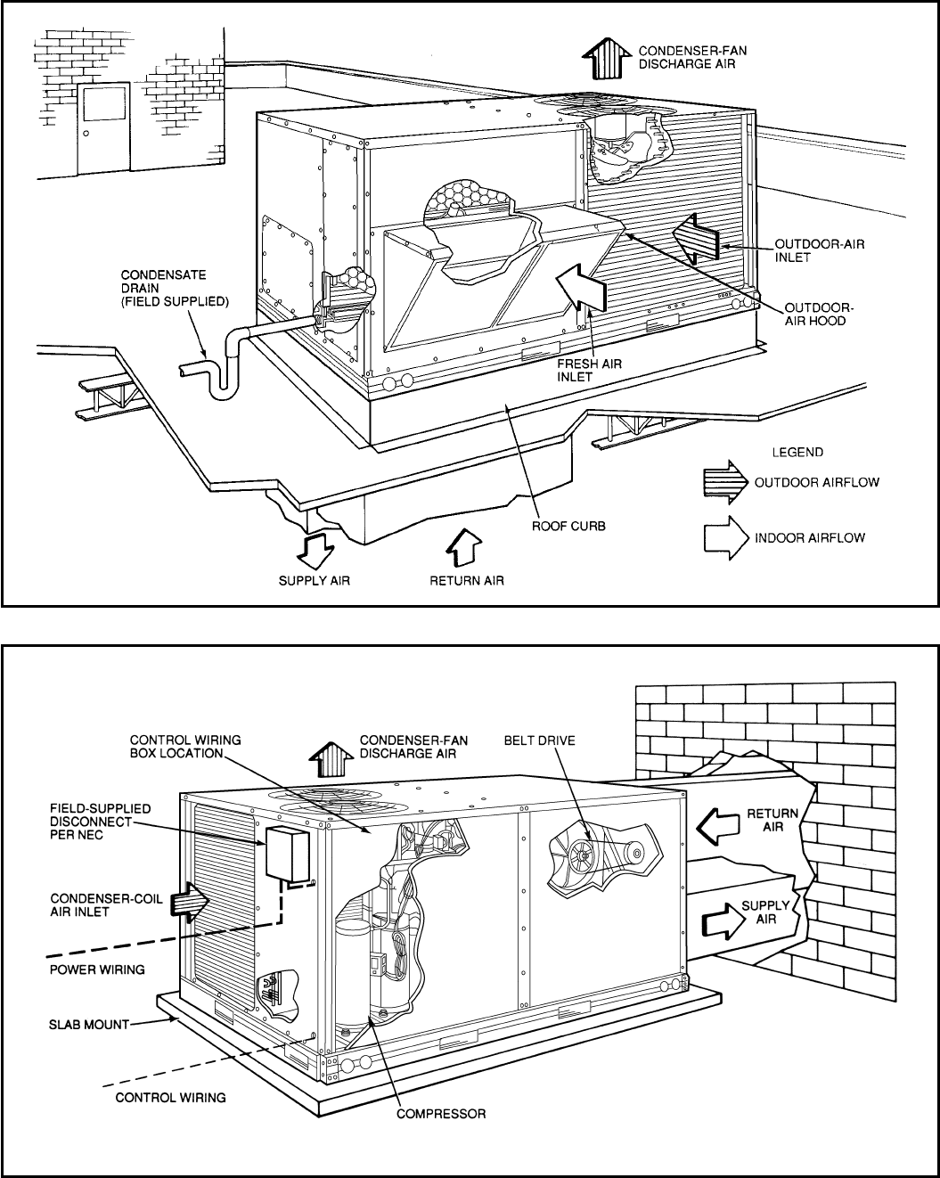
TYPICAL INSTALLATION — 558D090-150
Vertical Discharge Ducting
NEC — National Electrical Code
Horizontal Discharge Ducting
58
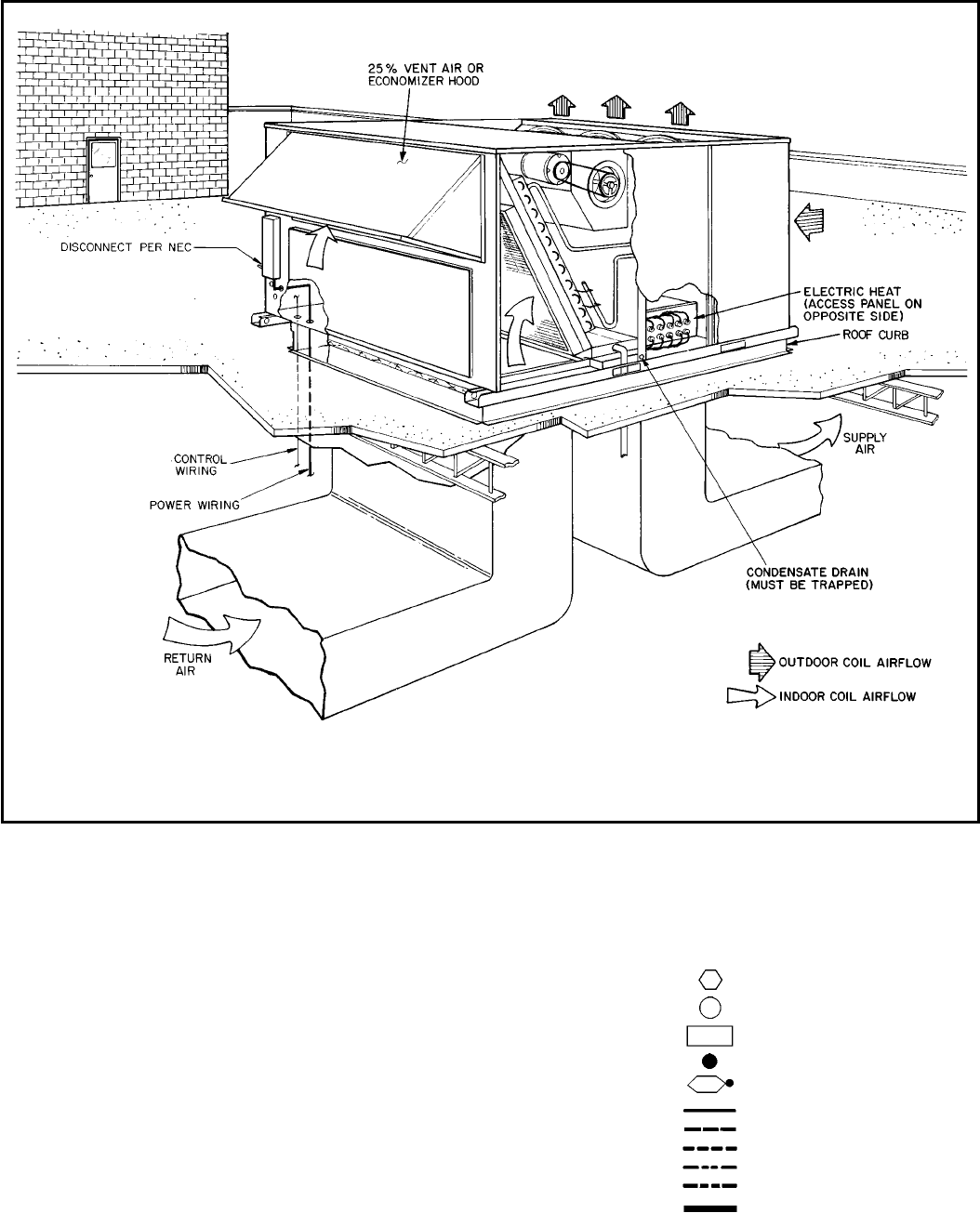
TYPICAL INSTALLATION — 559F180-300
NEC — National Electrical Code
NOTES:
1. Illustration shown is a general guide only and is not intended to
include all details for any specific installation.
2. Installation must comply with all applicable codes.
LEGEND FOR TYPICAL WIRING SCHEMATICS
AHA — Adjustable Heat Anticipator
BRK W/AT — Breaks With Amp Turns
C—Contactor, Compressor
CB — Circuit Breaker
CC — Cooling Compensator
CH — Crankcase Heater
CLO — Compressor Lockout
CLS — Compressor Lockout Switch
COMP — Compressor Motor
CT — Current Transformer
DM — Damper Motor
DU — Dummy Terminal
EC — Enthalpy Control
EQUIP — Equipment
FL — Fuse Link
FPT — Freeze Protection Thermostat
FU — Fuse
GND — Ground
HC — Heater Contactor
HPS — High-Pressure Switch
HTR — Heater
IFC — Indoor (Evaporator) Fan Contactor
IFCB — Indoor (Evaporator) Fan Circuit Breaker
IFM — Indoor (Evaporator) Fan Motor
IFR — Indoor (Evaporator) Fan Relay
IP — Internal Protector
L—Light
LOR — Lockout Relay
LPS — Low-Pressure Switch
LS — Limit Switch
MAT — Mixed-Air Thermostat
NC — Normally Closed
NEUT — Neutral
NO — Normally Open
OAT — Outdoor-Air Thermostat
OFC — Outdoor (Condenser) Fan Contactor
OFM — Outdoor (Condenser) Fan Motor
OP — Overcurrent Protector
PL — Plug Assembly
PRI — Primary
QT — Quadruple Terminal
SW — Switch
SW1 — Switch, Fully Open
SW2 — Switch, Fully Closed
SW3 — Switch, Minimum Vent Position
SW4 — Switch, Maximum Vent Position
TB — Terminal Block
TC — Thermostat Cooling
TH — Thermostat Heating
TRAN — Transformer
Terminal (Marked)
Terminal (Unmarked)
Terminal Block
Splice
Splice (Marked)
Factory Wiring
Field Control Wiring
Field Power Wiring
Accessory Wiring or Optional Wiring
Accessory
To indicate common potential only,
not to represent wiring
59

APPLICATION DATA
1. Units approved for outdoor installation only.
2. Ductwork (036-150) — Secure vertical discharge ductwork
to roof curb. For horizontal discharge applications, either at-
tach ductwork to unit, or use field-supplied flanges attached
to the horizontal discharge openings and attach all duct-
work to flanges.
3. Ductwork (180-300) — Ductwork should be attached to the
curb on all units. Interior installation may proceed before
unit is set in place on roof. If ductwork is to be attached to
unit, do not drill in condensate drain pan area — leaks may
result. Field-fabricated concentric ductwork may be con-
nected as shown on page 61.
4. On 180-300 size units with electric heat, a field-supplied
90° elbow must be installed in the supply ductwork below
the unit discharge connection.
5. To convert from vertical discharge to horizontal discharge
(036-150):
a. Remove Durablade economizer or two-position damper
to gain access to return duct opening.
b. Move the horizontal-discharge duct opening covers to
the vertical discharge openings.
c. Rotate economizer or two-position damper 90 degrees.
d. Rotate the barometric relief damper 90 degrees.
e. Install block-off plate over the opening on the access
panel.
NOTE: Parablade economizer is only used for vertical dis-
charge units.
6. Roof curb connections allow field power wires and control
wires to enter through the roof curb opening.
7. Use of 2-stage heating and cooling thermostat is recom-
mended for all units. A 2-stage cooling thermostat is re-
quired on units with accessory economizer to provide
integrated cooling.
8. All units are automatic changeover from heating to cooling
when automatic changeover thermostat and subbase are
used.
9. Units are draw-thru on cooling and blow-thru on heating.
10. To minimize the possibility of condensate blow-off from
evaporator, airflow through units should not exceed
500 cfm/ton on 036-240 units and 11,250 cfm on 300 units.
11. For cooling minimum airflow is 300 cfm/ton for 036-240
units and 280 cfm/ton on 300 units. For units with electric
heating, required minimum cfm is 900 for 036; 1200 for 048;
1500 for 060; 1800 for 072; 2250 for 090; 2550 for 102; and
3000 for 120 and 150, with the following exceptions:
UNIT
558D UNIT
VOLTAGE HEATER
kW UNIT
CONFIGURATION
REQUIRED
MINIMUM
CFM
120,
150
208/230 42.4 Horizontal 3200
208/230 50.0 Horizontal 3200
460 50.0 Horizontal or
Vertical 3200
090-
150 575 18.0 Horizontal or
Vertical 2800
36.0 2350
NOTE: The 180-300 units with electric heating have a required
minimum heating of 300 cfm/ton.
12. Minimum ambient cooling operating temperature
(036-150) — The minimum temperature for size 036-150
standard units is 25 F. With accessory low-ambient kit, units
can operate at outdoor temperatures down to –20 F.
13. Minimum ambient cooling operation temperature
(180-300) — Units are designed to operate at outdoor tem-
peratures down to 40 F for 180, 35 F for 216, 25 F for 240,
and 48 F for 300. To operate at lower outdoor temperatures,
see Trade Prices or contact your local representative for
appropriate accessories.
14. Due to the internal unit design (draw-thru over the motor),
air path, and specially designed motors, the full horsepower
(maximum continuous bhp) listed in the Specifications table
and the notes following each Air Delivery table can be uti-
lized with confidence.
Using motors with the values listed in the Specifications
table
will not
result in nuisance tripping or premature motor
failure. The unit warranty will not be affected.
60
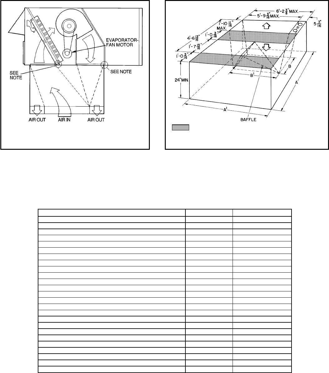
APPLICATION DATA (cont)
OPTION AND ACCESSORY LIST
ITEM OPTION* ACCESSORY†
Durablade Economizer (036-150; Includes Hood) XX
Parablade Economizer (036-150) X
Integrated Economizer (180-300) XX
Manual Outdoor-Air Dampers** X X††
Controls Upgrade Kit (036-150)|XX
Condenser Coil Grille (036-150) XX
Alternate Drive (090) X
Alternate Motor and Drive (036-060, 120, 150) X
Electric Heat and Single Point Kits X¶
25% Open Two-Position Damper X
100% Open Two-Position Damper (036-150) X
Barometric Relief Damper (180-300) X
Roof Curbs (Horizontal and Vertical) X
Horizontal Adapter (180-300) X
Thermostats and Subbases X
Power Exhaust (180-300) X
Head Pressure Control Device X
Low-Ambient Kits X
Time GuardTII Control Circuit X
Thru-the-Bottom Power Connections Packages (036-150) X
Solid-State Enthalpy Control (036-150) X
Enthalpy Control Sensor X
Condenser Coil Hail Guard Assembly (036-150) X
Winter Start Time-Delay Relay (216-300) X
Fan/Filter Status (036-150) X
*Factory installed.
†Field installed.
**Factory installed on 180-300 units whenever factory-installed economizer is not selected.
††Only available as an accessory on 036-150 units.
\Includes high-pressure, low-pressure/loss of charge, and freeze protection switches.
¶Electric heat for 575-v units is only offered on 558D090-180 units. Electric heat is field-installed on all units.
NOTE: Do not drill in this area, damage to basepan may result in water
leak.
Shaded area indicates block-off panels.
NOTE: Dimension A, A8and B, B8are obtained from field-supplied ceiling
diffuser.
Concentric Duct Air Distribution
(180-300 Only) Concentric Duct Details (180-300 Only)
61

APPLICATION DATA (cont)
EVAPORATOR-FAN MOTOR PERFORMANCE
UNIT EVAPORATOR-FAN
MOTOR UNIT
VOLTAGE
MAXIMUM
ACCEPTABLE
CONTINUOUS
BHP*
MAXIMUM
ACCEPTABLE
OPERATING
WATTS
MAXIMUM
AMP DRAW
558D036
Standard
208/230
0.34 440
2.9
460 1.4
575 1.4
Alternate
208/230
1.00 1000
5.1
460 2.3
575 2.3
558D048
Standard
208/230
0.75 850
3.7
460 1.9
575 1.9
Alternate
208/230
1.00 1000
5.1
460 2.3
575 2.3
558D060
Standard
208/230
1.20 1340
6.2
460 3.4
575 3.4
Alternate
208/230
1.80 1921
6.1/9.2†
460 2.7
575 2.7
558D072 Standard
208/230
2.40 2120
6.1
460 2.7
575 2.7
558D090 Standard
208/230
2.40 2120
6.1
460 2.7
575 2.7
558D102 Standard
208/230
2.40 2120
6.1
460 2.7
575 2.7
558D120
Standard
208/230
2.40 2120
6.1
460 2.7
575 2.7
Alternate
208/230
2.90 2615
7.9
460 3.6
575 3.6
558D150
Standard
208/230
4.20 3775
12.6
460 5.7
575 5.7
Alternate
208/230
5.25 4400
15.0
460 7.4
575 7.4
559F180 Standard
208/230 4.25 3775 10.5
460 4.8
575 3.45 3065 3.9
559F216 Standard
208/230
5.90 5180
15.8
460 7.9
575 6.0
559F240 Standard
208/230 8.70 7915 25.0
460 9.50 8640 13.0
575 8.70 7915 10.0
559F300 Standard
208/230 10.26 9510 28.0
460 11.80 11,000 14.6
575 10.26 9510 13.0
LEGEND
BHP — Brake Horsepower
*Extensive motor and electrical testing on these units ensures that the full horsepower range of the motors can be
utilized with confidence. Using your fan motors up to the horsepower ratings shown in this table will not result in
nuisance tripping or premature motor failure. Unit warranty will not be affected.
†Single phase/3 phase.
62
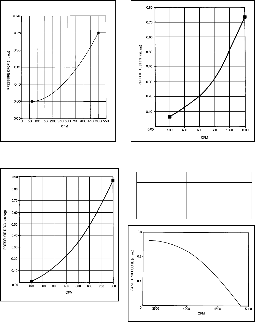
APPLICATION DATA (cont)
Durablade Economizer/Two-Position Damper
Barometric Relief Damper Characteristics
(558D036-150 Only)
Parablade Economizer Barometric Relief
Damper Characteristics — 558D090-150
Parablade Economizer Barometric Relief
Damper Characteristics — 558D036-072
EVAPORATOR-FAN MOTOR EFFICIENCY
UNIT MOTOR EFFICIENCY
(%)
558D036,048 75
558D060 74
558D072 84
558D090-120 80
558D150 87
559F180 84
559F216 83
559F240 84
559F300 81
Fan Performance Using Accessory
Power Exhaust (559F180-300)
63
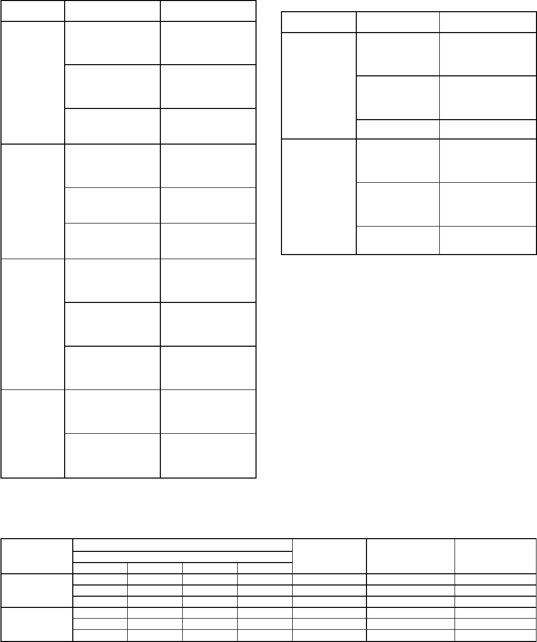
ELECTRIC HEATER CAPACITIES — 558D036-150
UNIT
558D VOLTAGE
(60 Hz) ACCESSORY
kW
036
208/230
(single phase)
4.4
6.5
8.7
10.5
13.0*
208/230
(3 phase)
4.4
6.5
8.7
10.5
16.0
460
(3 phase)
6.0
8.8
11.5
14.0
048
208/230
(single phase)
4.4
8.7
13.0*
17.4*
21.0*
208/230
(3 phase)
6.5
8.7
16.0
21.0*
460
(3 phase)
6.0
11.5
14.0*
23.0*
060
208/230
(single phase)
6.5
8.7
13.0*
17.4*
21.0*
208/230
(3 phase)
6.5
10.5
16.0
21.0*
26.5*
460
(3 phase)
6.0
11.5
14.0
23.0*
25.0*
072
208/230
(3 phase)
6.5
10.5
16.0
21.0*
26.5*
460
(3 phase)
6.0
11.5
14.0
23.0*
25.5*
ELECTRIC HEATER CAPACITIES —
558D036-150 (cont)
UNIT
558D VOLTAGE
(60 Hz) ACCESSORY
kW
090,102
208/230
(3 phase)
10.4
16.0
24.8
32.0
42.4*
460
(3 phase)
13.9
16.5
27.8
33.0
41.7*
575
(3 phase) 18.0
36.0
120,150
208/230
(3 phase)
10.4
16.0
32.0
42.4*
50.0*
460
(3 phase)
16.5
27.8
33.0
41.7*
50.0*
575
(3 phase)
18.0
36.0
54.0*
*Two heater packages required to provide kW indicated.
NOTES:
1. The kW ratings shown above are at 240, 480, and 575 v. Use the
Electric Heat Multiplication Factors table on page 48 to determine
heater capacity for your particular voltage.
2. Heaters are not available for size 036-072, 575-v units.
ELECTRIC RESISTANCE HEATER DATA — 559F180-300
UNIT
559F
HEATER kW HEATER
STAGES % HEAT
PER STAGE MAXIMUM
STAGES*
Unit Voltages
208 230 460 575
180
26 34 32 — 2 50/50 2
42 56 55 — 2 33/67 3
56 75 80 50 2 50/50 4
216-300
26 34 32 — 2 50/50 2
42 56 55 — 2 33/67 3
56 75 80 — 2 50/50 4
*Maximum number of stages using accessory low-ambient kit or head pressure control device and low-
ambient kit.
NOTE: Heaters are rated at 240 v, 480 v, and 575 v.
64

ENGINEERS’ SPECIFICATION GUIDE — MODELS 558D036-150 (3 TO 12
1
⁄
2
TONS)
GENERAL: Furnish and install single-package, outdoor rooftop-
mounted, electrically controlled cooling unit utilizing a recipro-
cating compressor. Unit shall discharge supply air vertically or
horizontally as shown on the contract drawings.
Nominal unit electrical characteristics shall be v,
phase, 60 Hz. The unit shall be capable of satisfac-
tory operation within voltage limits of vto v.
COOLING CAPACITY: Total cooling capacity of the unit shall
be Btuh or greater, and sensible capacity shall be
Btuh or greater at conditions of cfm evapo-
rator air entering unit at F dry bulb, F wet
bulb and condenser entering air of F dry bulb. Total
design conditions shall be a minimum of Btuh/Watt.
CABINET: The cabinet shall be constructed of galvanized steel,
bonderized, and coated with a prepainted baked enamel finish.
COMPRESSOR: Compressor shall be of the fully-hermetic type
with suitable vibration isolators.
CONDENSER SECTION: The condenser coils shall have alu-
minum plate fins mechanically bonded to seamless copper
tubes with all joints brazed. Condenser fan shall be of the direct-
drive propeller type and shall discharge air vertically. Fan shall
have permanently lubricated bearings.
EVAPORATOR SECTION: Evaporator coils shall have alumi-
num plate fins mechanically bonded to seamless copper tubes
with all joints brazed. Evaporator fan shall be direct drive with 2
or 3 speeds or belt drive as shown on the equipment drawings.
Belt drive shall include an adjustable pitch motor pulley. Bear-
ings shall be sealed, permanently lubricated, ball-bearing type.
REFRIGERANT SYSTEM: Refrigerant system shall include
strainer assembly, fixed orifice feed system, and service gage
connections on suction line, liquid line, and compressor dis-
charge line.
FILTER SECTION: Filter section shall consist of factory-
installed low velocity, 2-in. thick throwaway fiberglass filters of
commercially available sizes. Filter access panel shall provide
tool-less filter removal.
CONTROLS: Unit shall be complete with self-contained low-
voltage control circuit. Safeties shall include compressor over-
temperature and overcurrent.
APPROVALS: The unit shall be CSA (036-072) or UL Canada
(090-150) design certified and UL tested and certified. All wiring
shall be in accordance with NEC, and units shall meet ASHRAE
Standard 62. The unit shall be rated in accordance with ARI
Standards 210/240 or 360 and 270. Units shall be designed to
conform to NRCA standards. Insulation and adhesive shall
meet NFPA 90A requirements for flame spread and smoke
generation.
OPTIONS: Factory-installed integrated economizer shall in-
clude all hardware and controls to provide cooling using outdoor
air alone, or in conjunction with mechanical cooling. Dampers
shall be low leakage type, not to exceed 3% leakage at
1.0 in. wg pressure differential. Economizer shall be capable of
introducing up to 100% outdoor air and shall be equipped with a
barometric relief damper. Economizer controls shall be dry-bulb
(variable sliding plate type economizer) or enthalpy (parallel-
opposed blade type economizer) type. Damper shall close on
power loss.
Other factory-installed options shall include: 25% and 100%
manual outdoor-air dampers, controls upgrade kit, condenser
coil grille, and alternate evaporator-fan motors (036-060,
120,150) and/or drives (036-060,090,120,150).
ACCESSORIES: Field-installed accessories shall include:
Variable sliding plate type economizer, roof curb (14 or 24 in.),
two-position dampers, 25% and 50% manual outdoor-air damp-
ers, low ambient kit, short cycle circuit protection, thermostats
and subbases, condenser coil hail guard, enthalpy control, elec-
tric resistance heaters, single point packages, controls upgrade
kit, thru-the-bottom power connection package, condenser coil
grille, head pressure control, fan/filter status, and enthalpy con-
trol sensor.
65
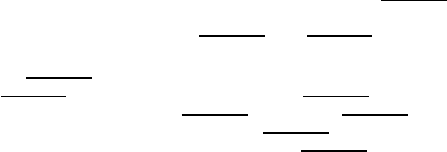
ENGINEERS’ SPECIFICATION GUIDE — MODELS 559F180-300 (15 TO 25 TONS)
GENERAL: Furnish and install single-package, outdoor rooftop-
mounted, electrically controlled cooling unit utilizing reciprocat-
ing compressor(s) for cooling. Unit shall discharge supply air
vertically or horizontally as shown on the contract drawings.
Nominal unit electrical characteristics shall be v,
3 phase, 60 Hz. The unit shall be capable of satisfactory opera-
tion within voltage limits of vto v.
COOLING CAPACITY: Total cooling capacity of the unit shall
be Btuh or greater, and sensible capacity shall be
Btuh or greater at conditions of cfm evapo-
rator air entering unit at F dry bulb, F wet
bulb and condenser entering air of F dry bulb. Total
design conditions shall be a minimum of Btuh/Watt.
CABINET: The cabinet shall be constructed of galvanized steel,
bonderized and coated with a prepainted baked enamel finish.
COMPRESSOR: Compressor(s) shall be of the semi-hermetic
type with crankcase heaters, and shall have spring vibration iso-
lators and dual independent refrigeration circuits (216-300).
CONDENSER SECTION: The condenser coils shall have alu-
minum plate fins mechanically bonded to seamless copper
tubes with all joints brazed. Condenser fan shall be of the direct-
driven propeller type and shall discharge air vertically. Fan shall
have permanently lubricated bearings.
EVAPORATOR SECTION: Evaporator coils shall have alumi-
num plate fins mechanically bonded to seamless copper tubes
with all joints brazed. Evaporator fan shall be belt driven as
shown on the equipment drawings. Motor bearings shall be
sealed, permanently lubricated, ball-bearing type.
REFRIGERANT SYSTEM: Refrigerant system shall include fil-
ter drier, fixed orifice feed system, and service gage connec-
tions on suction line, liquid line, and compressor discharge line,
as well as low-pressure and high-pressure protection.
FILTER SECTION: Filter section shall consist of factory-
installed low velocity, 2-in. thick throwaway fiberglass filters of
commercially available sizes. Filter access panel shall be easy
access.
CONTROLS: Unit shall be complete with self-contained low-
voltage control circuit. Safeties shall include compressor over-
temperature and overcurrent.
APPROVALS: The unit shall be ETL and ETL Canada tested
and certified. All wiring shall be in accordance with NEC, and
units shall meet ASHRAE Standard 62. The unit (except 300)
shall be rated in accordance with ARI Standards 360 and 270.
Units shall be designed to conform to NRCA standards. Insula-
tion and adhesive shall meet NFPA 90A requirements for flame
spread and smoke generation.
OPTIONS: Factory-installed integrated economizer shall in-
clude all hardware and controls to provide cooling using outdoor
air alone, or in conjunction with mechanical cooling. Dampers
shall be low leakage type, not to exceed 2% leakage at
1.0 in. wg pressure differential. Economizer shall be capable of
introducing up to 100% outdoor air and shall be equipped with a
gravity relief damper. Economizer controls shall be dry-bulb
type.
On all units where the factory-installed economizer is not cho-
sen, the factory-installed manual outdoor-air damper shall be
included.
ACCESSORIES: Field-installed accessories shall include:
Economizer, roof curbs (14 or 24 in.), horizontal adapter, two-
position damper, low ambient kit, short cycle circuit protection,
thermostats and subbases, enthalpy control sensor, winter start
time-delay relay, electric resistance heaters, barometric relief
damper, power exhaust, and head pressure control device.
66

Bryant
Air Conditioning
Copyright 1996 Carrier Corporation
SPECIFICATIONS SUBJECT TO CHANGE WITHOUT NOTICE
UNIT MUST BE INSTALLED IN ACCORDANCE
WITH INSTALLATION INSTRUCTIONS
Printed in U.S.A. 6/96 CATALOG NO. BY-3255-818
