Bryant Heat Recovery Ventilator Ervbblha Users Manual Pdservhrvlha 01
ERVBBLHA to the manual af77fbe0-638b-4acb-a79f-86867416098d
2015-02-02
: Bryant Bryant-Heat-Recovery-Ventilator-Ervbblha-Users-Manual-412182 bryant-heat-recovery-ventilator-ervbblha-users-manual-412182 bryant pdf
Open the PDF directly: View PDF ![]() .
.
Page Count: 10
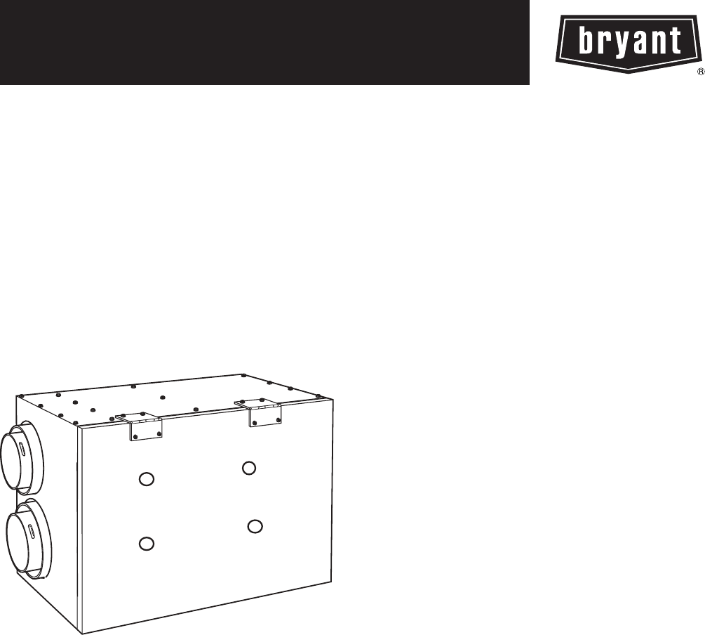
HRVBBLHA
Heat Recovery Ventilator
ERVBBLHA
Energy Recovery Ventilator
Product Data
A10299
The Heat Recovery Ventilation (HRV) and Energy Recovery
Ventilator (ERV) systems offered by Bryant are the finest on the
market today. These units provide efficient and cost effective heat
recovery during the heating season when needed most.
As temperatures drop below 23_F(--5_C), indoor air is recirculated
periodically through the heat exchanger core to prevent frost from
forming. Competitors’ methods of supplementary electric defrost
waste energy. Unlike rotary wheel heat exchangers which mix air
streams, these cross--flow or counterflow heat exchangers ensure
that there is no mixing of the stale air stream with the fresh outdoor
air stream.
A filter installed on the incoming outdoor air stream removes large
airborne particles from the intake air stream before they enter the
heat exchanger and reduces the maintenance required. The units’
acoustically engineered design make Bryant ventilators the quietest
on the market and ensures that comfort is felt, not heard.
Unlatching two (2) suitcase style latches allows easy removal of the
filters and core for cleaning.
NOTE: The HRV should not be installed in an attic or
unconditioned space unless provisions are made for drain line
freezing and condensation.
STANDARD FEATURES
HRV
SEnergy saving defrost cycle
SCross--flow, counterflow heat exchangers
SOne filter on incoming air; one filter on outgoing air to
protect core
SAcoustical design
SNo--tools maintenance
SPolypropylene heat exchanger core
ERV
SDrainless design
SIntegrated airflow balancing points
SIntegrated furnace interlock
SHigh pressure blowers
SOnboard control for continuous high/low ventilator operation
SEnergy saving defrost cycle
SCross--flow, counterflow heat exchangers
SOne filter on incoming air; one filter on outgoing air to
protect core
SNo--tools maintenance
SEnthalpic heat exchanger core
2
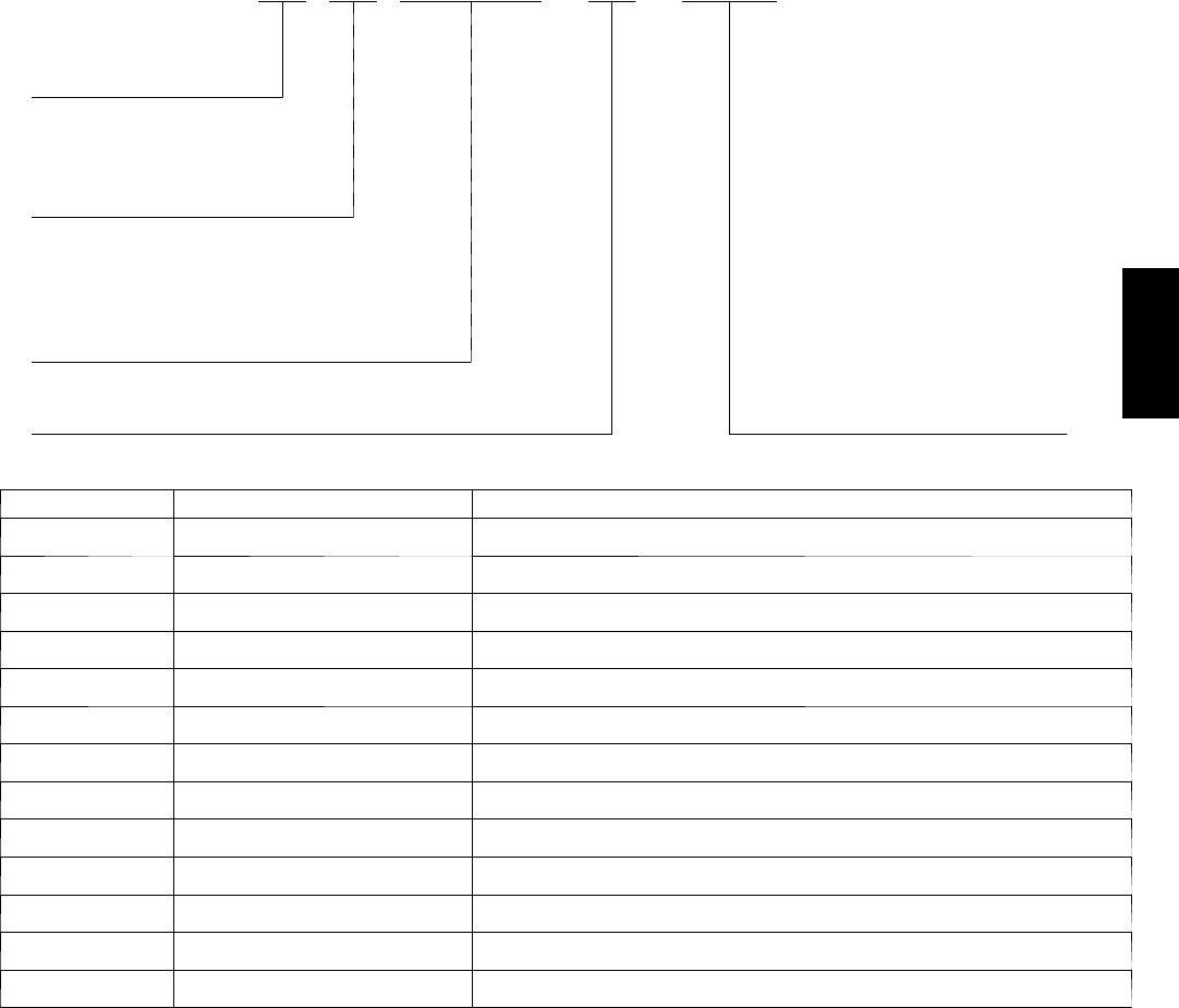
MODEL NUMBER NOMENCLATURE
123456789101112
ERVBBLHA1150
Product Type Maximum Capacity
ERV -- Energy Recovery Ventilator 150 -- 150 CFM
HRV -- Heat Recovery Ventilator 200 -- 200 CFM
250 -- 250 CFM
Brand
BB -- Bryant Electrical Supply
1 -- 115 Volts
Style
LHA -- Large Horizontal
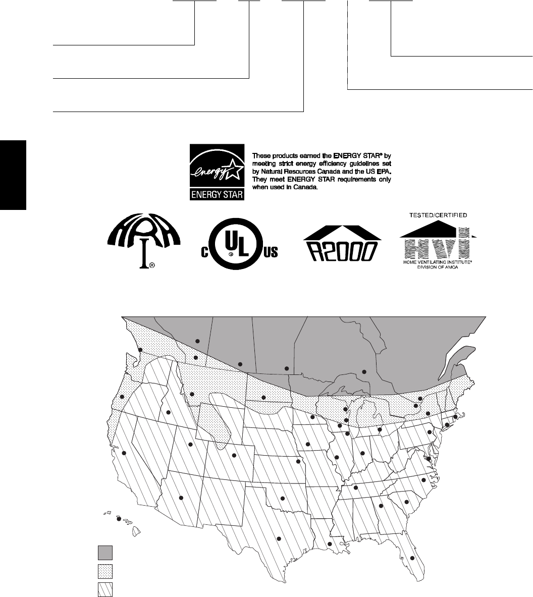
Climate Map for Energy and Heat Recovery Ventilators
ERV Recommended w/HRV or ERV Wall Control
ERV Recommended
HRV Recommended
Honolulu
Sacramento Salt Lake
City
Boise
Salem
Vancouver
Helena
Edmonton
Calgary Regina Winnipeg
Bismark
Topeka
Denver
Oklahoma City
Austin
Baton Rouge
Orlando
Atlanta Columbia
Raleigh
Washington D.C.
Nashville
Indianapolis
Springfield
Chicago
Des Moines
Minneapolis
Green Bay
Milwaukee
Detroit
Madison
Harrisburg
Hartford
Boston
Syracuse
Montreal
Ottawa
Timmins
A00099
ERV / HRV
3
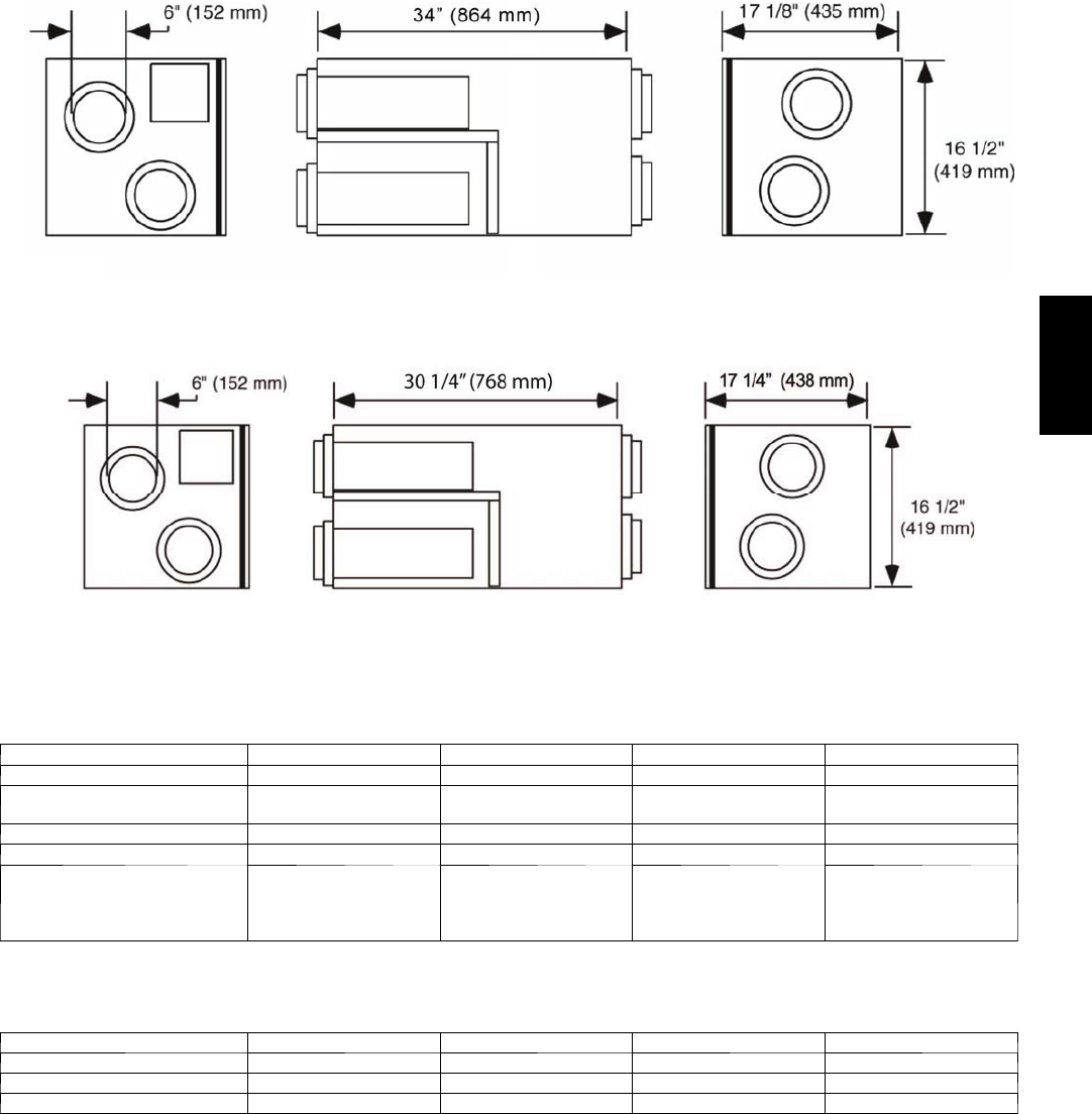
DIMENSIONS
A10318
Fig. 1 -- ERVBBLHA1150 / ERVBBLHA1200 Dimensions
A10319
Fig. 2 -- HRVBBLHA1150 / HRVBBLHA1250 Dimensions
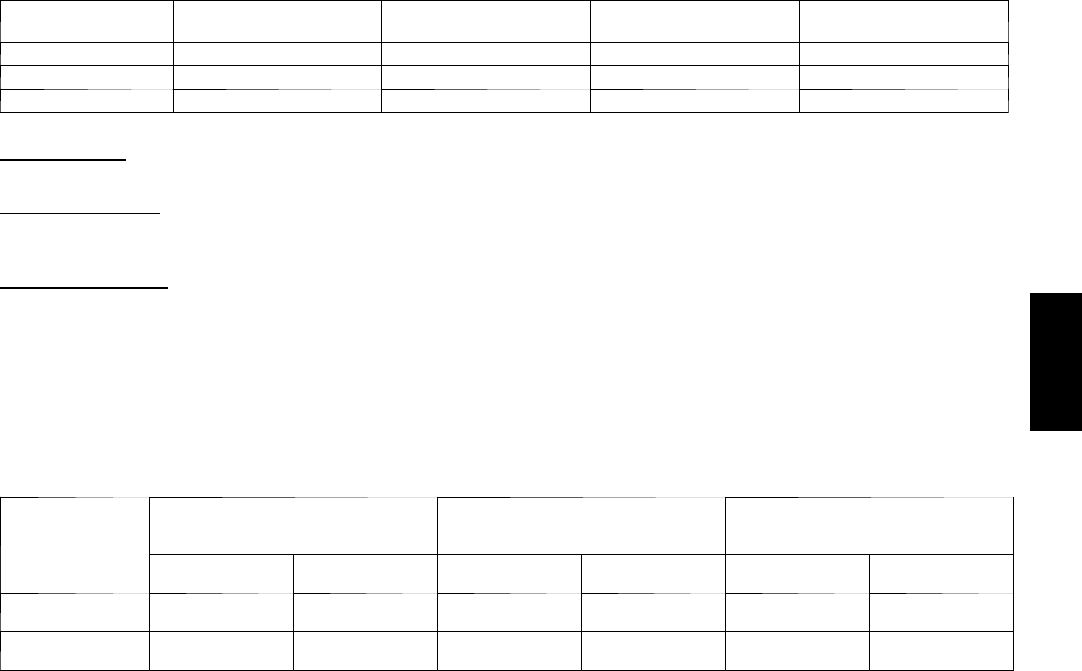
PHYSICAL DATA
MODEL ERVBBLHA1150 ERVBBLHA1200 HRVBBLHA1150 HRVBBLHA1250
Port Locations Sides Sides Side Side
Core Type Enthalpic transfer
media, Cross Flow
Enthalpic transfer
media, Cross Flow
Polypropylene
Cross Flow
Polypropylene
Cross Flow
Weight — lb (kg) 74 (33.6) 76 (34.5) 65 (29.5) 73 (33.2)
Shipping Weight — lb (kg) 78 (35.4) 80 (36.3) 75 (34) 83 (37.6)
Shipping Dimensions in. (mm)
Height
Width
Length
19.75 (502)
20.5 (521)
40.5 (1029)
19.75 (502)
20.5 (521)
40.5 (1029)
23-1/16
36-1/16
17-13/16
22-15/16
35-1/16
22-15/16
ELECTRICAL DATA
MODEL ERVBBLHA1150 ERVBBLHA1200 HRVBBLHA1150 HRVBBLHA1250
Voltage 120 120 120 120
Max Power — watts 150 240 150 218
Max Amps 1.3 2.1 1.4 1.9
ERV / HRV
4
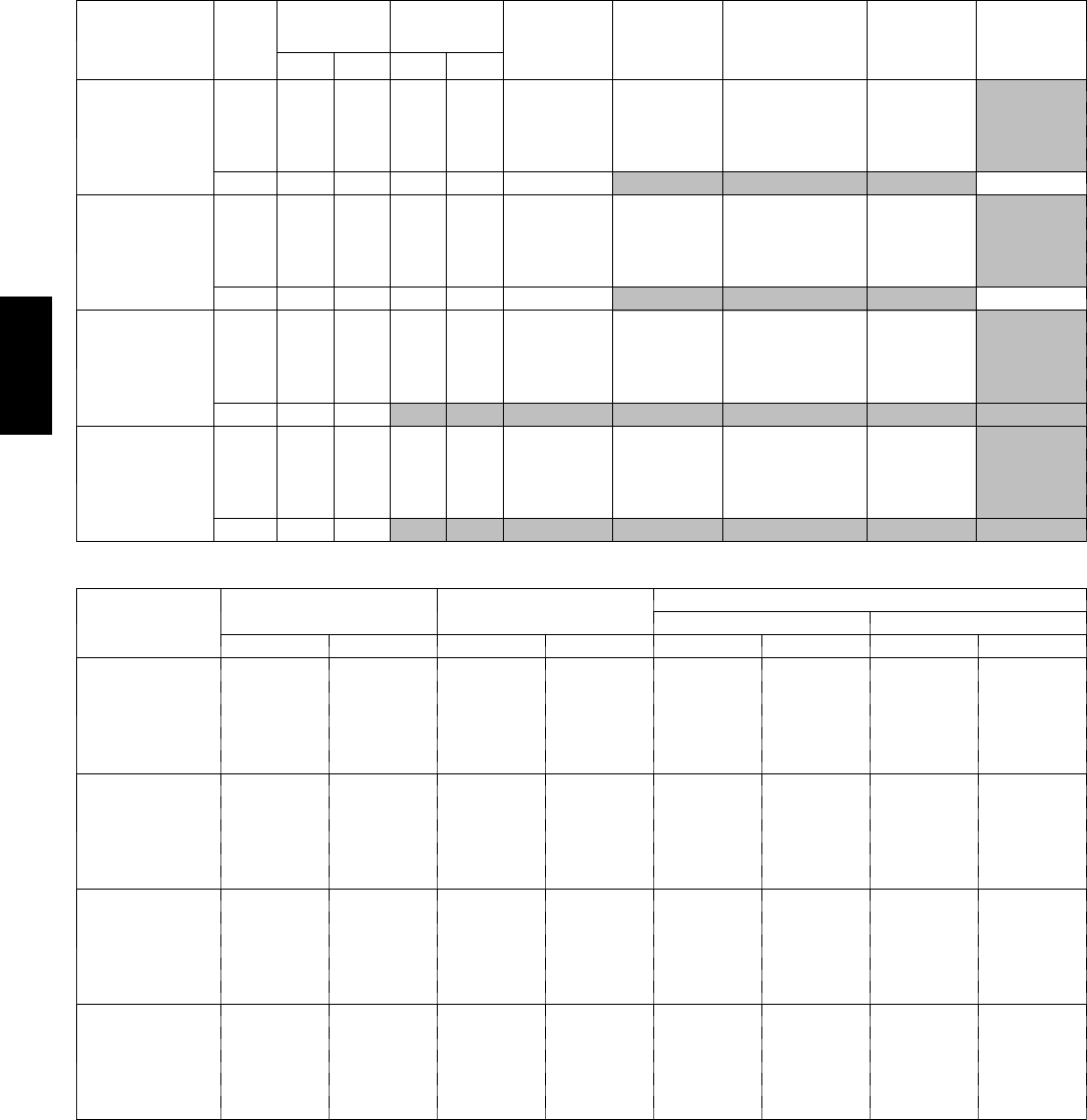
PERFORMANCE DATA
HVI Rated Energy Performance
MODEL MODE
SUPPLY
TEMP
NET
AIR FLOW POWER
CONSUMED
(WATTS)
SENSIBLE
RECOVERY
EFFICIENCY
APPARENT
SENSIBLE
EFFECTIVE-
NESS
LATENT
RECOVERY
MOISTURE
TRANSFER
TOTAL
RECOVERY
EFFICIENCY
_C_FL/S CFM
ERVBBLHA1150 Heat
032 30 64 66 61 75 0.62
032 46 97 77 60 71 0.58
032 66 141 137 57 69 0.52
--- 2 5 --- 1 3 22 47 92 49 80 0.56
Cool 35 95 31 65 63 56
ERVBBLHA1200 Heat
032 39 80 84 60 72 0.60
032 54 114 113 58 69 0.53
032 79 167 169 56 66 0.45
--- 2 5 --- 1 3 31 65 116 41 86 0.47
Cool 35 95 39 82 81 52
HRVBBLHA1150 Heat
032 31 66 85 69 81 0
032 56 119 124 60 70 0
032
--- 2 5 --- 1 3 34 72 114 62 80 0.08
Cool 35 95
HRVBBLHA1250 Heat
032 31 66 85 69 81 0
032 56 119 124 60 70 0
032 86 182 197 53 62 0
--- 2 5 --- 1 3 34 72 114 62 80 0.08
Cool 35 95
Ventilation Performance
MODEL
EXT. STATIC
PRESSURE
NET SUPPLY
AIR FLOW
GROSS AIR FLOW
SUPPLY EXHAUST
PA IN W.G. L/S CFM L/S CFM L/S CFM
ERVBBLHA1150
25 0.1 84 179 85 181 92 196
75 0.3 74 156 75 158 85 181
100 0.4 70 148 71 151 77 163
150 0.6 58 124 59 125 54 114
200 0.8 41 87 42 88 20 43
ERVBBLHA1200
25 0.1 105 222 106 225 106 225
75 0.3 93 198 94 200 100 212
100 0.4 86 183 88 186 93 198
150 0.6 70 148 71 150 75 158
200 0.8 50 107 51 108 29 61
HRVBBLHA1150
25 0.1 83 175 83 176 83 175
75 0.3 75 159 75 159 75 158
100 0.4 71 150 71 151 69 146
150 0.6 59 126 60 127 49 103
200 0.8 43 91 43 91 21 45
HRVBBLHA1250
25 0.1 110 234 112 237 112 237
75 0.3 98 208 100 211 99 210
100 0.4 89 189 91 192 91 193
150 0.6 71 151 72 153 70 149
175 0.7 64 136 65 138 44 94
NOTE: For additional data points, refer to HVI Directory at www.hvi.org
ERV / HRV
5
CONTROL FEATURES
CONTROL
DESCRIPTION
FAN SPEED
CONTROL
DEHUMIDISTAT
CONTROL
CONTINUOUS
MODE
INTERMITTENT
MODE
OneTouch Yes No Yes Yes
Basic Yes No Yes No
Standard Yes Yes Yes Yes
Basic Control:
Allows the user to manually set fan speed to low or high as required to maximize comfort.
Standard Control:
Offers automatic dehumidistat control and the option to select continuous or intermittent fan operation. Setting the wall control to low will
activate the continuous mode.
OneTouch Control:
Allows control of ventilator with the touch of a button. This control will operate as a main wall control. The OneTouch will operate the unit
in Intermittent Mode (20 minutes per hour), continuous low speed, continuous high speed, and off.
AUTOMATIC DEFROST CYCLE FEATURES
All models offer a non--electric defrost cycle feature which prevents frost and ice buildup within the heat recovery core. When the outside air
temperature falls below 23_F(--5_C) it is electronically sensed and the dampers close the outside air ports. This allows warm indoor air to
recirculate within the heat recovery core. The frequency of this cycle increases as the outside air temperature decreases.
MODEL
25_FTO55_F
( --- 5 _C T O --- 1 5 _C)
4_F T O --- 1 7 _F
( --- 1 5 . 6 _C T O --- 2 7 . 3 _C)
B E L O W --- 1 8 _F
( --- 2 7 . 8 _C)
DEFROST* EXCHANGE{DEFROST* EXCHANGE{DEFROST* EXCHANGE{
ERVBBLHA 6 Minutes 60 Minutes 6 Minutes 32 Minutes 6 Minutes 20 Minutes
HRVBBLHA 6 Minutes 60 Minutes 6 Minutes 32 Minutes 6 Minutes 20 Minutes
* All defrost times are in the standard mode (as shipped)
{Time between defrost when within specified temperature range
ERV / HRV
6
METHOD TO SIZE ERVs and HRVs
Ventilator Sizing
Tables 1 and 2 should be used to determine the required airflow for a home. These guidelines are taken from ASHRAE 62.2--2007.
Table 1 – Ventilation Air Requirements, cfm
FLOOR
AREA (ft2)
BEDROOMS
0 --- 1 2 --- 3 4 --- 5 6 --- 7 >7
<1500 30 45 60 75 90
1501---3000 45 60 75 90 105
3001---4500 60 75 90 105 120
4501---6000 75 90 105 120 135
6001---7500 90 105 120 135 150
>7500 105 120 135 150 165
Table 2 – Ventilation Air Requirements, L/s
FLOOR
AREA (m2)
BEDROOMS
0 --- 1 2 --- 3 4 --- 5 6 --- 7 >7
<139 14 21 28 35 42
139.1---279 21 28 35 42 50
279.1---418 28 35 42 50 57
418.1---557 35 42 50 57 64
557.1---697 42 50 57 64 71
>697 50 57 64 71 78
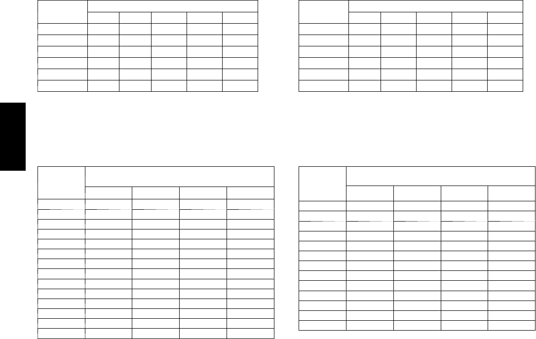
HEATING AND COOLING LOAD CHARTS
Although the ventilators process the outside air before it enters the home, additional heating and cooling loads need to be considered.
HEATING LOAD BTUH
Outside
Temp °F
Heating Load (Btuh) @
Inside Design Temp 72°F
ERV1150 ERV1200 HRV1150 HRV1250
–25 5186 8143 6636 10603
–20 4919 7723 6294 10057
–15 5075 7967 5952 9510
–10 4783 7509 5610 8964
–5 4491 7051 5268 8417
04200 6594 4925 7871
54234 6647 4583 7324
10 3918 6151 4241 6777
15 3958 6214 3899 6231
20 3611 5669 3557 5684
25 3264 5124 3215 5138
30 2916 4579 2873 4591
35 2569 4034 2531 4045
40 2222 3489 2189 3498
The heating load chart shows the heating loads in Btuh for a range
of winter design temperatures for each model of ventilator.
EXAMPLE: The heating design temperature for Little Rock, AR is
20_F. The additional heating load of the ERVBBLHA1200 at
20_F is 559 Btuh. This additional load should be taken into
consideration when sizing the heating equipment.
COOLING LOAD BTUH
Outside
Enthalpy
Btu/lb
Cooling Load (Btuh) @ Inside Design Temp
72°F and 50% Relative Humidity
ERV1150 ERV1200 HRV1150 HRV1250
30 380 640 670 1071
31 618 1040 1090 1741
32 855 1441 1509 2411
33 1093 1841 1928 3080
34 1331 2241 2347 3750
35 1568 2641 2766 4419
36 1806 3041 3185 5089
37 2043 3441 3604 5759
38 2281 3842 4023 6428
39 2519 4242 4442 7098
40 2756 4642 4861 7767
41 2994 5042 5280 8437
42 3231 5442 5699 9107
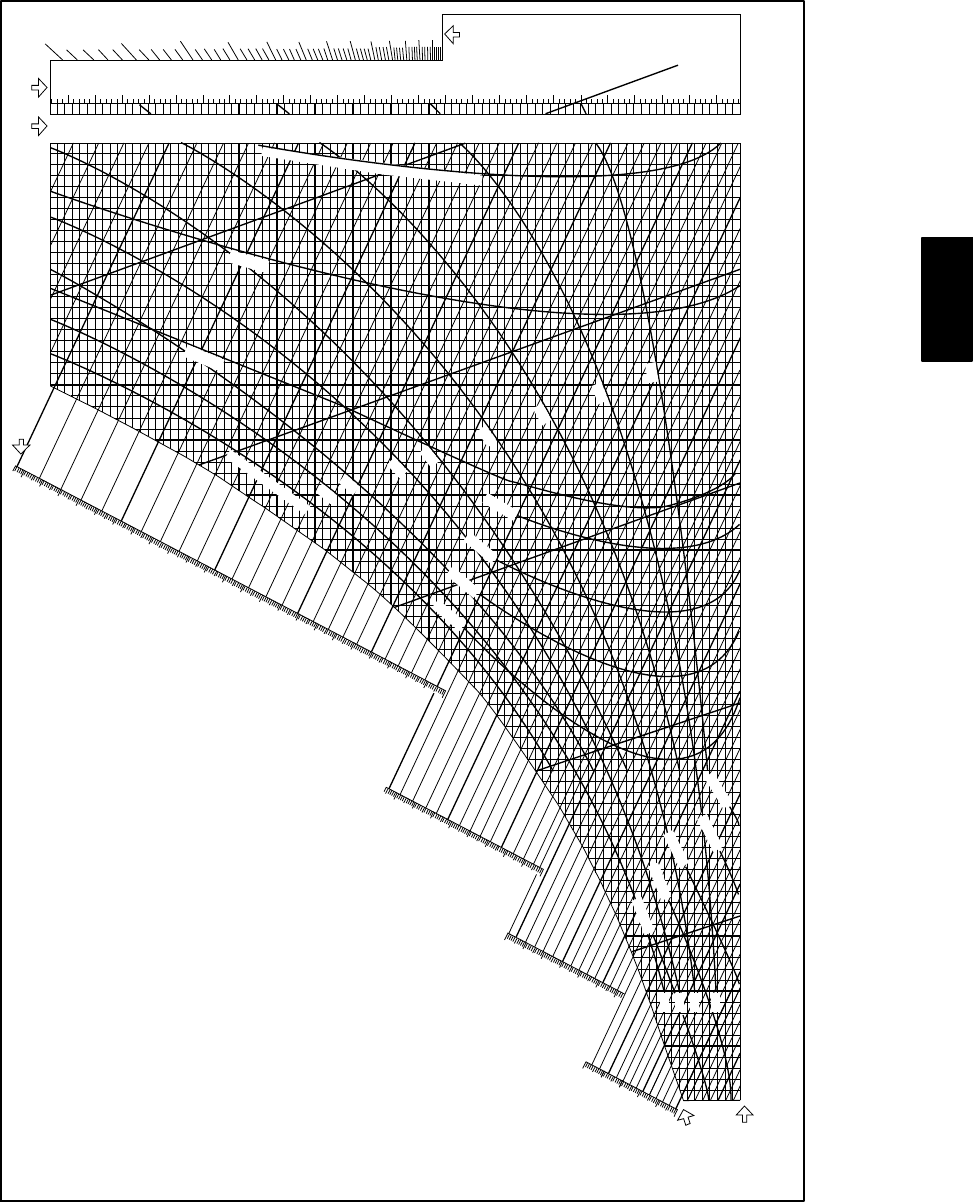
The cooling load chart shows loads in Btuh as well. To use the
cooling load chart, first find the design enthalpy from a
psychrometric chart using the design dry bulb and wet bulb
temperatures. The cooling load can then be found for a range of
enthalpies for each ventilator.
EXAMPLE: The design dry bulb temperature for Miami is 90_F
and the average wet bulb at that temperature is 77_F. Using the
psychrometric chart, the enthalpy is about 40.5 Btu per pound
(Btu/lb) of dry air, which would round up to 41 Btu/lb dry air. In
the left column, at 41 Btu/lb dry air, the ERVBBLHA1200 has an
additional cooling load of 5042 Btuh, while the HRV1150CFM
unit has an additional cooling load of 8437 Btuh.
ERV / HRV
7
PSYCHOMETRIC CHART
.025
.024
.023
.022
.021
.020
.019
.018
.017
.016
.015
.014
.013
.012
.95
.90
.85
.80
.75
.70
.65
.60
.55
.50
.45
.40
.35
.011
.010
.009
.008
.007
.006
.005
.004
.003
.002
.001
0
Sensible
heat
factor
Pounds of moisture
per pound of dry air
789
10 11
12
32 33
34 35
36
37 38
39 40
41
42 43
44 45
47
48 49
46
27 28
29 30
31
19 20
21 22
23
24 25
26
12 13
14 15
16
17
18
Wet Bulb,
Dewpoint or
Saturation
Temperature F
Dry Bulb
Temperature F
20
Below 32˚F, properties and enthalpy deviation lines are for ice.
25
25 30 35
40
45 50 55
60
65
70 75
80
30 35 40
85 90 95 100 105 180
170
160
150
140
130
120
110
100
90
80
70
60
50
40
30
20
10
0
45 50 55 60 65 70 75 80 85 90 95 100 105 110
Enthalpy at saturation, Btu per pound of dry air
Grains of moisture
per pound of dry air
14.0 cu ft
14.5 cu ft per pound of dry air
13.5 cu ft
13.0 cu ft
12.5 cu ft
90% Relative Humidity
80%
70%
60%
50%
40%
30%
20%
10%
-.02 BTU
-.01 BTU
-.02 Btu
-.04 Btu
-.06 Btu
-.08 Btu
+0.1 Btu
+0.2 Btu
+0.3 Btu
+0.4 Btu
+0.5 Btu
80%
60%
40%
20%
Btu per
pound of dry air -0.3 Btu
Enthalpy deviation
A989394
ERV / HRV
8
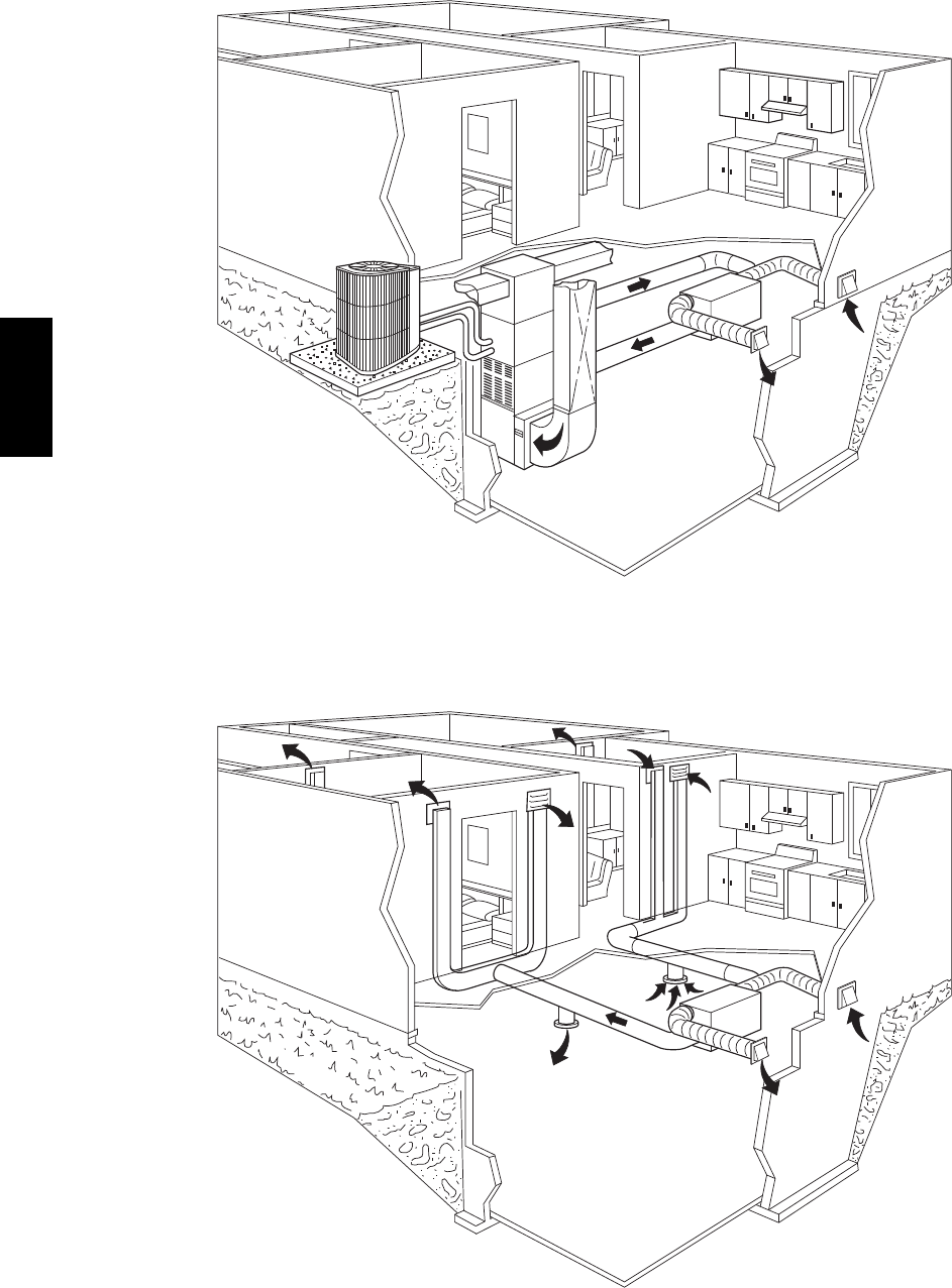
Ventilator installed with forced air system
A99297
Ventilator installed with independent air distribution
A99298
ERV / HRV
9
ACCESSORIES
VENTILATOR ACCESSORY NUMBER NOMENCLATURE
123456789101112
KVBCN0101BBS
Product Control Description
BAU -- Bryant Automatic Control
KV -- Ventilator Accessory Kit BBS -- Bryant Basic Control
BLC -- Bryant Latent Control
BLT -- Bryant OneTouch Control
Series BST -- Bryant Standard Control
A -- Original Series
B -- Second Series Accessory Description
HOD -- Intake Hood
Type KIT -- Airflow Measuring Kit
AC01 -- Accessory 6FM -- Flow Collar 6--in.
CN01 -- Control 7FM -- Flow Collar 7--in.
TM01 -- Timer 8FM -- Flow Collar 8--in.
AC01 -- Accessory
Timer Description
Package Quantity 120C -- 20 Minute Timer Kit
01 -- Single Pack 160M -- 60 Minute Timer Kit
KIT NUMBER DESCRIPTION WHERE USED
KVBCN0101BAU Automatic Wall Control Used with HRVs
KVBCN0101BBS Basic Wall Control Used with HRVs
KVBCN0101BLC Latent Wall Control Used with ERVs
KVBCN0101BLT Bryant OneTouch Control UsedwithERVsandHRVsasamainwallcontrol
KVBCN0101BST Standard HRV Control Used with HRVs
KVAAC0101HOD Exterior Intake and Exhaust Hood Used with ERVs and HRVs, 2 Required
KVBAC0101KIT Airflow Measuring Kit Start up Balancing Kit, includes (2) 6 in. Flow Meter Collars & Magnehelic Gauge
KVATM010120C 20 Minute Push Button Timer Used with ERVs and HRVs when 20 minute manual operation is required
KVATM010160M 60 Minute Timer Used with ERVs and HRVs, time is adjustable between 10 and 60 minutes
KVAAC01016FM 6 in. Flow Meter Collar Used with ERVs and HRVs, at start up, when 6 in. duct work is connected to HRV
KVAAC01017FM 7 in. Flow Meter Collar Used with ERVs and HRVs, at start up, when 7 in. duct work is connected to HRV
KVAAC01018FM 8 in. Flow Meter Collar Used with ERVs and HRVs, at start up, when 8 in. duct work is connected to HRV
KVAFK0201150 Internal Filter Used with HRVBBLHA1150, HRVBBLHA1250 Unit 15 1/2 in. x 7 in. x 5/8 in.
ERV / HRV

10
Manufacturer reserves the right to discontinue, or change at any time, specifications or designs without notice and without incurring obligations.
E2010 Bryant Heating & Cooling Systems D7310 W. Morris St. DIndianapolis, IN 46231 Printed in U.S.A. Edition Date: 07/10
Replaces: NEW
Catalog No. PDSER
V
HR
V
LH
A
--- 0 1
ERV / HRV
