Bryant Liquid Cooled Prepackaged Standby Generators Aspas1Bbl025 Users Manual
ASPAS1BBL025 to the manual e0ef20ea-287a-4cbd-9b7a-5d19261b6ae1
2015-02-02
: Bryant Bryant-Liquid-Cooled-Prepackaged-Standby-Generators-Aspas1Bbl025-Users-Manual-412122 bryant-liquid-cooled-prepackaged-standby-generators-aspas1bbl025-users-manual-412122 bryant pdf
Open the PDF directly: View PDF ![]() .
.
Page Count: 56
Owner’s Manual
ONLY QUALIFIED ELECTRICIANS OR CONTRACTORS
SHOULD ATTEMPT INSTALLATION!!
This manual should remain with the unit.
Liquid-cooled, Prepackaged
Standby Generators
Model No. ASPAS1BBL025 (25kW)
Bryant
INTRODUCTION
Thank you for purchasing a Bryant home standby
generator system.
Every effort was expended to make sure that the
information and instructions in this manual are both
accurate and current at the time the manual was writ-
ten. However, the manufacturer reserves the right to
change, alter or otherwise improve this product(s) at
any time without prior notice.
READ THIS MANUAL THOROUGHLY
If any portion of this manual is not understood, con-
tact the nearest dealer for starting, operating and
servicing procedures.
Throughout this publication, and on tags and decals
affixed to the generator, DANGER, WARNING, CAU-
TION and NOTE blocks are used to alert personnel to
special instructions about a particular service or oper-
ation that may be hazardous if performed incorrectly
or carelessly. Observe them carefully. Their definitions
are as follows:
After this heading, read instructions that, if not
strictly complied with, will result in serious person-
al injury, including death, or considerable property
damage.
After this heading, read instructions that, if not
strictly complied with, may result in personal injury
or property damage.
After this heading, read instructions that, if not
strictly complied with, could result in damage to
equipment and/or property.
NOTE:
After this heading, read explanatory statements
that require special emphasis.
These safety warnings cannot eliminate the hazards
that they indicate. Common sense and strict compli-
ance with the special instructions while performing the
service are essential to preventing accidents.
Four commonly used safety symbols accompany the
DANGER, WARNING and CAUTION blocks. The type
of information each indicates is as follows:
This symbol points out important safety informa-
tion that, if not followed, could endanger personal
safety and/or property of others.
This symbol points out potential explosion hazard.
This symbol points out potential fire hazard.
This symbol points out potential electrical shock
hazard.
The operator is responsible for proper and safe use
of the equipment. Bryant strongly recommends that
the operator reads this Owner's Manual and thor-
oughly understands all instructions before using this
equipment. Bryant also strongly recommends
instructing other users to properly start and operate
the unit. This prepares them if they need to operate
the equipment in an emergency.
OPERATION AND MAINTENANCE
It is the operator's responsibility to perform all safety
checks, to make sure that all maintenance for safe
operation is performed promptly, and to have the
equipment checked periodically by a dealer. Normal
maintenance service adjustments and replacement of
parts are the responsibility of the owner/operator and,
as such, are not considered defects in materials or
workmanship within the terms of the warranty.
Individual operating habits and usage contribute to
the need for maintenance service.
Proper maintenance and care of the generator ensures
a minimum number of problems and keep operating
expenses at a minimum. See a dealer for service aids
and accessories.
Operating instructions presented in this manual
assume that the standby electric system has been
installed by a dealer or other competent, qualified
contractor. Installation of this equipment is not a “do-
it-yourself” project.
HOW TO OBTAIN SERVICE
When the generator requires servicing or repairs,
contact a dealer for assistance. Service technicians
are factory-trained and are capable of handling all
service needs.
When contacting a Bryant Dealer about parts and
service, always supply the complete model number
and serial number of the unit as given on the front
cover of this manual and on the DATA LABEL affixed
to the unit.
!
DANGER
YOUR BRYANT DEALER IS:
___________________________________________
___________________________________________
___________________________________________
___________________________________________
Model No.__________ Serial No.___________
Dealer Name
Address
City State Zip Code
Phone Number

Table of Contents
Bryant Liquid-cooled 25 kW Generator
Bryant 1
INTRODUCTION................................................IFC
Read this Manual Thoroughly......................................IFC
Operation and Maintenance ........................................IFC
How to Obtain Service ................................................IFC
SAFETY RULES ....................................................2
Section 1 — GENERAL INFORMATION ............4
1.1 Generator ..............................................................4
1.2 Transfer Switch ....................................................4
1.3 Automatic System Operation ................................4
1.4 Generator AC Connection Systems........................4
1.5 Main Circuit Breaker ............................................4
1.6 Generator Fuel System ..........................................5
1.7 Engine Protective Devices ......................................5
1.8 Unpacking ............................................................6
1.9 Lifting the Generator ............................................6
1.10 Specifications ........................................................6
1.11 Fuel Consumption ................................................7
1.12 Reconfiguring the Fuel System for LP Vapor..........7
1.13 Engine Oil Recommendations ..............................7
1.14 Coolant Recommendations....................................8
1.15 Before Installation ................................................8
Section 2 — INSTALLATION ............................8
2.1 Standby Generator Installation ............................8
2.2 Generator Location................................................9
2.3 Generator Mounting and Support ........................9
2.4 Basic Standby Electric System ..............................9
2.5 Emergency Circuit Isolation Method......................9
2.6 Total Circuit Isolation Method ............................10
2.7 Grounding the Generator ....................................10
2.8 Generator AC Neutral Connections......................10
2.9 Transfer Switch Signal Connections....................10
2.10 Battery Installation ..............................................10
2.11 Preparation Before Start-Up ................................11
Section 3 — OPERATION ................................12
3.1 Engineered GTS Transfer Switch ........................12
3.2 Control Console Components..............................14
3.3 Manual Transfer and Startup..............................14
3.4 Engine Governor Adjustments ............................14
3.5 Retransfer and Shutdown....................................14
3.6 Automatic Operation ..........................................14
3.7 Weekly Exercise Cycle..........................................15
Section 4 — MAINTENANCE ..........................16
4.1 Maintenance Performed by Authorized
Service Facilities ..................................................16
4.2 Exhaust Manifold Procedure ..............................16
4.3 Intake Manifold Procedure ..................................16
4.4 Cylinder Head Procedure ....................................16
4.5 Cooling System....................................................17
4.6 Overload Protection for Engine DC
Electrical System ................................................17
4.7 Checking Fluid Levels ........................................17
4.8 Maintenance Owner/Operator
Can Perform ........................................................17
4.9 Miscellaneous Maintenance ................................19
4.10 Scheduled Maintenance ......................................21
Section 5 — TROUBLESHOOTING ..................24
Section 6 — NOTES ........................................25
Section 7 — ELECTRICAL DATA ....................28
Section 8 — EXPLODED VIEWS AND
PARTS LISTS ..............................36
Section 9 — INSTALLATION DIAGRAM ..........51
Section 10 — WARRANTY ...............................52
2 Bryant
Study these SAFETY RULES carefully before installing, operat-
ing or servicing this equipment. Become familiar with this
Owner’s Manual and with the unit. The generator can operate
safely, efficiently and reliably only if it is properly installed, oper-
ated and maintained. Many accidents are caused by failing to fol-
low simple and fundamental rules or precautions.
Bryant cannot anticipate every possible circumstance that
might involve a hazard. The warnings in this manual, and on
tags and decals affixed to the unit are, therefore, not all-inclu-
sive. If using a procedure, work method or operating technique
that Bryant does not specifically recommend, ensure that it is
safe for others. Also make sure the procedure, work method or
operating technique utilized does not render the generator
unsafe.
Despite the safe design of this generator, operating
this equipment imprudently, neglecting its mainte-
nance or being careless can cause possible injury or
death. Permit only responsible and capable persons
to install, operate or maintain this equipment.
Potentially lethal voltages are generated by these
machines. Ensure all steps are taken to render the
machine safe before attempting to work on the
generator.
Parts of the generator are rotating and/or hot
during operation. Exercise care near running gen-
erators.
GENERAL HAZARDS
• For safety reasons, Bryant recommends that this equip-
ment be installed, serviced and repaired by a Bryant Dealer
or other competent, qualified electrician or installation
technician who is familiar with applicable codes, standards
and regulations. The operator also must comply with all
such codes, standards and regulations.
• Installation, operation, servicing and repair of this (and
related) equipment must always comply with applicable
codes, standards, laws and regulations. Adhere strictly to
local, state and national electrical and building codes.
Comply with regulations the Occupational Safety and Health
Administration (OSHA) has established. Also, ensure that
the generator is installed, operated and serviced in accor-
dance with the manufacturer’s instructions and recommen-
dations. Following installation, do nothing that might render
the unit unsafe or in noncompliance with the aforemen-
tioned codes, standards, laws and regulations.
• The engine exhaust fumes contain carbon monoxide gas,
which can be DEADLY. This dangerous gas, if breathed in
sufficient concentrations, can cause unconsciousness or
even death. For that reason, adequate ventilation must be
provided. Exhaust gases must be piped safely away from
any building or enclosure that houses the generator to an
area where people, animals, etc., will not be harmed. This
exhaust system must be installed properly, in strict com-
pliance with applicable codes and standards.
• Keep hands, feet, clothing, etc., away from drive belts, fans,
and other moving or hot parts. Never remove any drive belt
or fan guard while the unit is operating.
• Adequate, unobstructed flow of cooling and ventilating air is
critical to prevent buildup of explosive gases and to ensure
correct generator operation. Do not alter the installation or
permit even partial blockage of ventilation provisions, as
this can seriously affect safe operation of the generator.
• Keep the area around the generator clean and uncluttered.
Remove any materials that could become hazardous.
• When working on this equipment, remain alert at all times.
Never work on the equipment when physically or mentally
fatigued.
• Inspect the generator regularly, and promptly repair or
replace all worn, damaged or defective parts using only fac-
tory-approved parts.
• Before performing any maintenance on the generator, dis-
connect its battery cables to prevent accidental start-up.
Disconnect the cable from the battery post indicated by a
NEGATIVE, NEG or (–) first. Reconnect that cable last.
• Never use the generator or any of its parts as a step.
Stepping on the unit can stress and break parts, and may
result in dangerous operating conditions from leaking
exhaust gases, fuel leakage, oil leakage, etc.
ELECTRICAL HAZARDS
• All generators covered by this manual produce dangerous
electrical voltages and can cause fatal electrical shock.
Utility power delivers extremely high and dangerous volt-
ages to the transfer switch as well as the standby generator.
Avoid contact with bare wires, terminals, connections, etc.,
on the generator as well as the transfer switch, if applicable.
Ensure all appropriate covers, guards and barriers are in
!!
!
!
DANGER
Important Safety Instructions
Bryant Liquid-cooled 25 kW Generator
SAVE THESE INSTRUCTIONS – The manufacturer suggests that these rules for safe
operation be copied and posted in potential hazard areas. Safety should be stressed to all
operators, potential operators, and service and repair technicians for this equipment.
!
!
SAVE THESE INSTRUCTIONS – This manual contains important instructions that should be
followed during installation and maintenance of the generator and batteries.
!
!
The engine exhaust from this product
contains chemicals known to the state
of California to cause cancer, birth
defects or other reproductive harm.
WARNING:
!!
This product contains or emits chemicals
known to the state of California to cause
cancer, birth defects or other reproductive harm.
WARNING:
!!

Bryant 3
place before operating the generator. If work must be done
around an operating unit, stand on an insulated, dry surface
to reduce shock hazard.
• Do not handle any kind of electrical device while standing
in water, while barefoot, or while hands or feet are wet.
DANGEROUS ELECTRICAL SHOCK MAY RESULT.
• If people must stand on metal or concrete while installing,
operating, servicing, adjusting or repairing this equipment,
place insulative mats over a dry wooden platform. Work on
the equipment only while standing on such insulative mats.
• The National Electrical Code (NEC), Article 250 requires
the frame and external electrically conductive parts of the
generator to be connected to an approved earth ground
and/or grounding rods. This grounding will help prevent
dangerous electrical shock that might be caused by a
ground fault condition in the generator set or by static elec-
tricity. Never disconnect the ground wire.
• Wire gauge sizes of electrical wiring, cables and cord sets
must be adequate to handle the maximum electrical current
(ampacity) to which they will be subjected.
• Before installing or servicing this (and related) equipment,
make sure that all power voltage supplies are positively
turned off at their source. Failure to do so will result in haz-
ardous and possibly fatal electrical shock.
• Connecting this unit to an electrical system normally sup-
plied by an electric utility shall be by means of a transfer
switch so as to isolate the generator electric system from the
electric utility distribution system when the generator is
operating. Failure to isolate the two electric system power
sources from each other by such means will result in dam-
age to the generator and may also result in injury or death
to utility power workers due to backfeed of electrical energy.
• Generators installed with an automatic transfer switch will
crank and start automatically when normal (utility) source
voltage is removed or is below an acceptable preset level. To
prevent such automatic start-up and possible injury to per-
sonnel, disable the generator’s automatic start circuit (bat-
tery cables, etc.) before working on or around the unit.
Then, place a “Do Not Operate” tag on the generator control
panel and on the transfer switch.
• In case of accident caused by electric shock, immediately
shut down the source of electrical power. If this is not pos-
sible, attempt to free the victim from the live conductor.
AVOID DIRECT CONTACT WITH THE VICTIM. Use a
nonconducting implement, such as a dry rope or board, to
free the victim from the live conductor. If the victim is
unconscious, apply first aid and get immediate medical
help.
• Never wear jewelry when working on this equipment.
Jewelry can conduct electricity resulting in electric shock,
or may get caught in moving components causing injury.
FIRE HAZARDS
• Keep a fire extinguisher near the generator at all times. Do
NOT use any carbon tetra-chloride type extinguisher. Its
fumes are toxic, and the liquid can deteriorate wiring insu-
lation. Keep the extinguisher properly charged and be
familiar with its use. Consult the local fire department for
any questions pertaining to fire extinguishers.
EXPLOSION HAZARDS
• Properly ventilate any room or building housing the gener-
ator to prevent build-up of explosive gas.
• Do not smoke around the generator. Wipe up any fuel or oil
spills immediately. Ensure that no combustible materials
are left in the generator compartment, or on or near the
generator, as FIRE or EXPLOSION may result. Keep the
area surrounding the generator clean and free from debris.
• Bryant generator sets may operate using one of several
types of fuels. All fuel types are potentially FLAMMABLE
and/or EXPLOSIVE and should be handled with care.
Comply with all laws regulating the storage and handling of
fuels. Inspect the unit’s fuel system frequently and correct
any leaks immediately. Fuel supply lines must be properly
installed, purged and leak tested according to applicable
fuel-gas codes before placing this equipment into service.
• Diesel fuels are highly FLAMMABLE. Gaseous fluids such
as natural gas and liquid propane (LP) gas are extremely
EXPLOSIVE. Natural gas is lighter than air, and LP gas is
heavier than air. Install leak detectors accordingly.
STANDARDS INDEX
In the absence of pertinent standards, codes, regulations and
laws, the published information listed below may be used as
installation guide for this equipment.
NOTE:
It is essential to use the latest version of any stan-
dard to ensure correct and current information.
1. NFPA No. 37, STATIONARY COMBUSTION
ENGINES AND GAS TURBINES, available from the
National Fire Protection Association, 470 Atlantic
Avenue, Boston, MA 02210.
2. NFPA No. 76A, ESSENTIAL ELECTRICAL SYS-
TEMS FOR HEALTH CARE FACILITIES, available
same as Item 1.
3. NFPA No. 54, NATIONAL FUEL GAS CODE, avail-
able same as Item 1.
4. NFPA No. 58, AMERICAN NATIONAL STANDARD
FOR STORAGE AND HANDLING OF LIQUEFIED
PETROLEUM GAS, available same as Item 1.
5. NFPA No. 70, NFPA HANDBOOK OF NATIONAL
ELECTRIC CODE, available same as Item 1.
6. Article X, NATIONAL BUILDING CODE, available
from the American Insurance Association, 85 John
Street, New York, N.Y. 10038.
7. AGRICULTURAL WIRING HANDBOOK, available
from the Food and Energy Council, 909 University
Avenue, Columbia, MO 65201.
8. ASAE EP-3634, INSTALLATION AND MAINTE-
NANCE OF FARM STANDBY ELECTRICAL SYS-
TEMS, available from the American Society of
Agricultural Engineers, 2950 Niles Road, St.
Joseph, MI 49085.
9. NFPA No. 30, FLAMMABLE AND COMBUSTIBLE
LIQUIDS CODE, available same as Item 1.
Important Safety Instructions
Bryant Liquid-cooled 25 kW Generator
4 Bryant
1.1 GENERATOR
This equipment is a liquid-cooled, engine-driven gen-
erator set. The generator is designed to supply elec-
trical power that operates critical electrical loads
during utility power failure. The unit has been facto-
ry-installed in a weather resistant, all metal enclosure
and is intended for outdoor installation only. Use this
generator as a source of electrical power for the oper-
ation of 120 and/or 240VAC, single-phase loads.
This model is rated as follows:
Model ASPAS1BBL025: Provides 25,000 watts (25 kW) of single-
phase power.
If this generator is used to power electrical load
circuits normally powered by a utility power
source, it is required by code to install a trans-
fer switch. The transfer switch must effectively
isolate the electric system from the utility distri-
bution system when the generator is operating
(NEC 701). Failure to isolate an electrical system
by such means results in damage to the genera-
tor and may also result in injury or even death
to utility power workers due to backfeed of
electrical energy.
1.2 TRANSFER SWITCH
This generator system is intended to be used with a
matched automatic transfer switch. It is supplied
with a NEMA 3R enclosure. The NEMA 3R enclosure
is weather proof and can be used indoors or out-
doors. Follow these rules:
• Install the transfer switch on a firm, sturdy sup-
porting structure.
• To prevent switch distortion, level the switch if nec-
essary. This can be done by placing washers
between the switch enclosure and the mounting
surface.
• Never install the switch where water or any corro-
sive substance might drip onto the enclosure.
• Protect the switch at all times against excessive
moisture, dust, dirt, lint, construction grit and cor-
rosive vapors.
If a transfer switch is not included, one may be pur-
chased separately from a dealer.
1.3 AUTOMATIC SYSTEM OPERATION
When this generator, along with a transfer switch, has
been installed and interconnected, a circuit board in
the generator panel constantly monitors utility power
source voltage. Should that voltage drop below a pre-
set value, and remain at such a low state for a preset
amount of time, the generator cranks and starts. After
the generator starts, the transfer switch transfers load
circuits so the generator can power them.
When utility source voltage has been restored, the
switch re-transfers back to the utility source voltage
and the generator then shuts down.
Please reference the transfer switch manual for spe-
cific information.
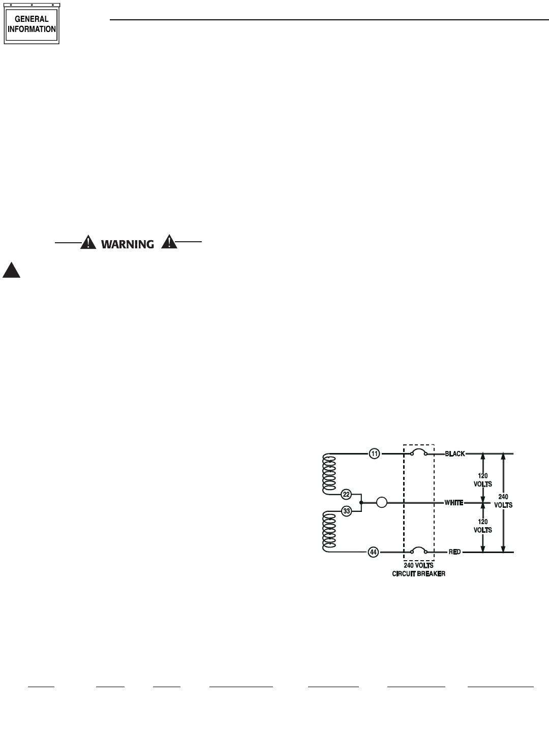
1.4 GENERATOR AC CONNECTION
SYSTEMS
The generator was shipped from the factory with its
stator AC output leads connected in a single-phase,
3-wire generator AC connection system (Figure 1.1).
The stator assembly in this system consists of a pair
of stationary windings, with two leads brought out of
each winding. Each single winding can supply 120
VAC, 60 Hertz. When the two windings are connected
in series, a 240 VAC, 60 Hertz AC output results.
Typically the two “hot” leads in the circuit are Wires
No. 11 and 44. The “Neutral” leads are the junction
of Wires 22 and 33.
Figure 1.1 - Generator AC Connection System
1.5 MAIN CIRCUIT BREAKER
The generator’s main circuit breaker is included with
the unit as shipped from the factory. The breaker for
each unit is described in Figure 1.2.
0
NEUTRAL
!
Section 1 - General Information
Bryant Liquid-cooled 25 kW Generator
Model Rating Phase Actual Current C/B Rating* % over rating Circuit Breaker
ASPAS1BBL025 25,000 W 1 104.2 A 125 A 120% 125A BQ2
* Amp Rating of C/B structured under model.
Figure 1.2 - Main Circuit Breaker
Bryant 5
1.6 GENERATOR FUEL SYSTEM
This unit has been factory tested and adjusted using
a natural gas fuel system. If propane (LP) gas is pre-
ferred, refer to Section 1.12, Reconfiguring the Fuel
System for LP Vapor.
Fuel pressure for a natural gas set up should be five
inches to 14 inches of water column (0.18 to 0.5
psi) at all load ranges.
Fuel pressure for an LP vapor set up should be 11
inches to 14 inches of water column (0.4 to 0.5
psi) at all load ranges.
NOTE:
A separate gas line and regulator may be needed
to assure proper gas pressure to the generator.
Improper gas pressure can cause hard starting and
affect engine durability.
Gaseous fuels such as natural and LP (propane)
gas are highly explosive. Even the slightest
spark can ignite such fuels and cause an explo-
sion. No leakage of fuel is permitted. Natural
gas, which is lighter than air, tends to collect in
high areas. LP gas is heavier than air and tends
to settle in low areas.
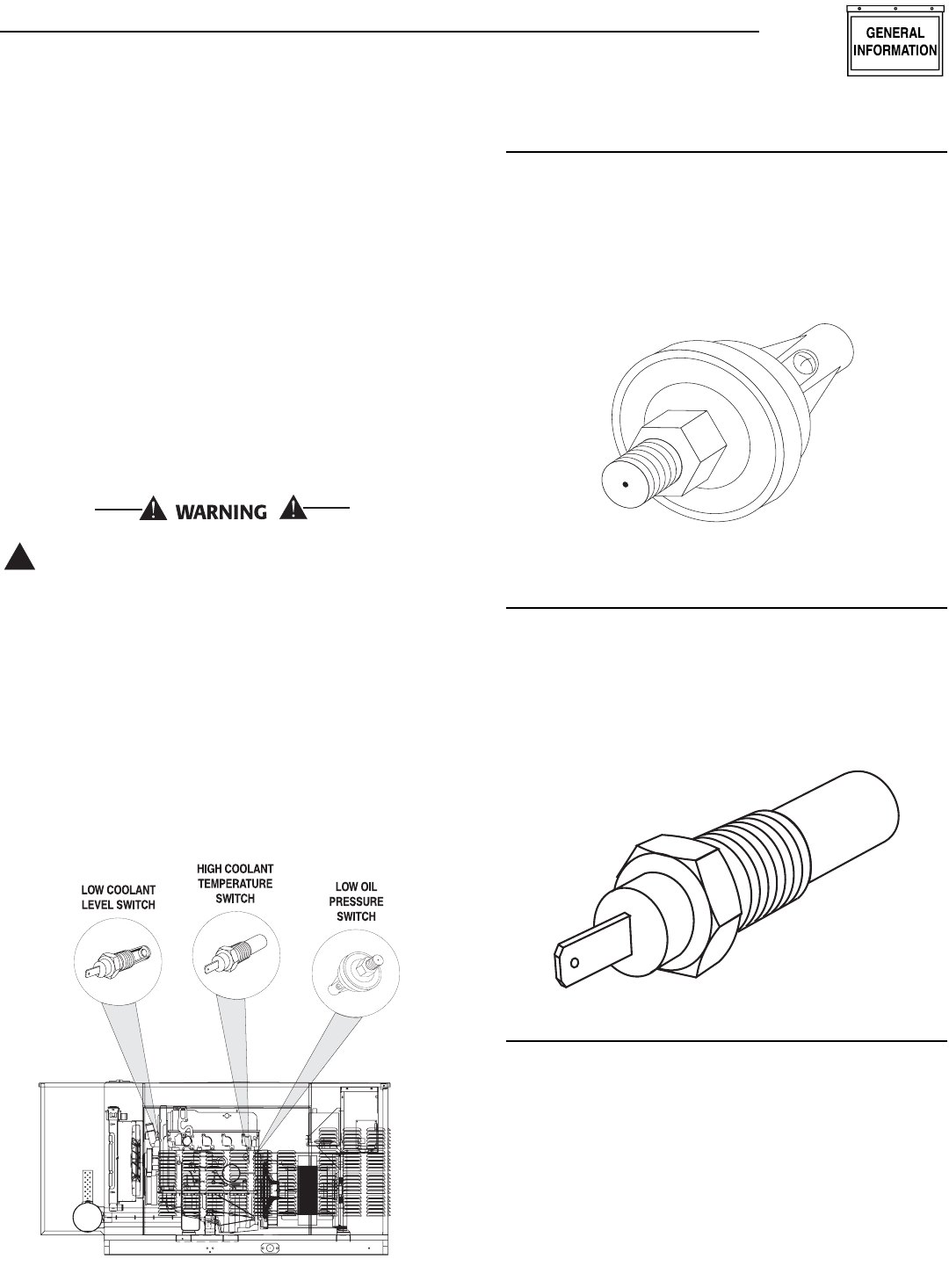
1.7 ENGINE PROTECTIVE DEVICES
The engine has several safety switches which cause
the engine to automatically shut down under the fol-
lowing conditions: low oil pressure, high coolant tem-
perature, engine overspeed, low coolant level or over-
crank (Figure 1.3).
Figure 1.3 - Engine Protective Devices
1.7.1 LOW OIL PRESSURE SWITCH
This switch is normally-closed (N.C.) but is held open
by engine oil pressure during engine running. Should
operating oil pressure drop below about 8-10 psi
(55-68 kPa), the switch contacts close and the engine
shuts down automatically (Figure 1.4).
Figure 1.4 - Low Oil Pressure Switch
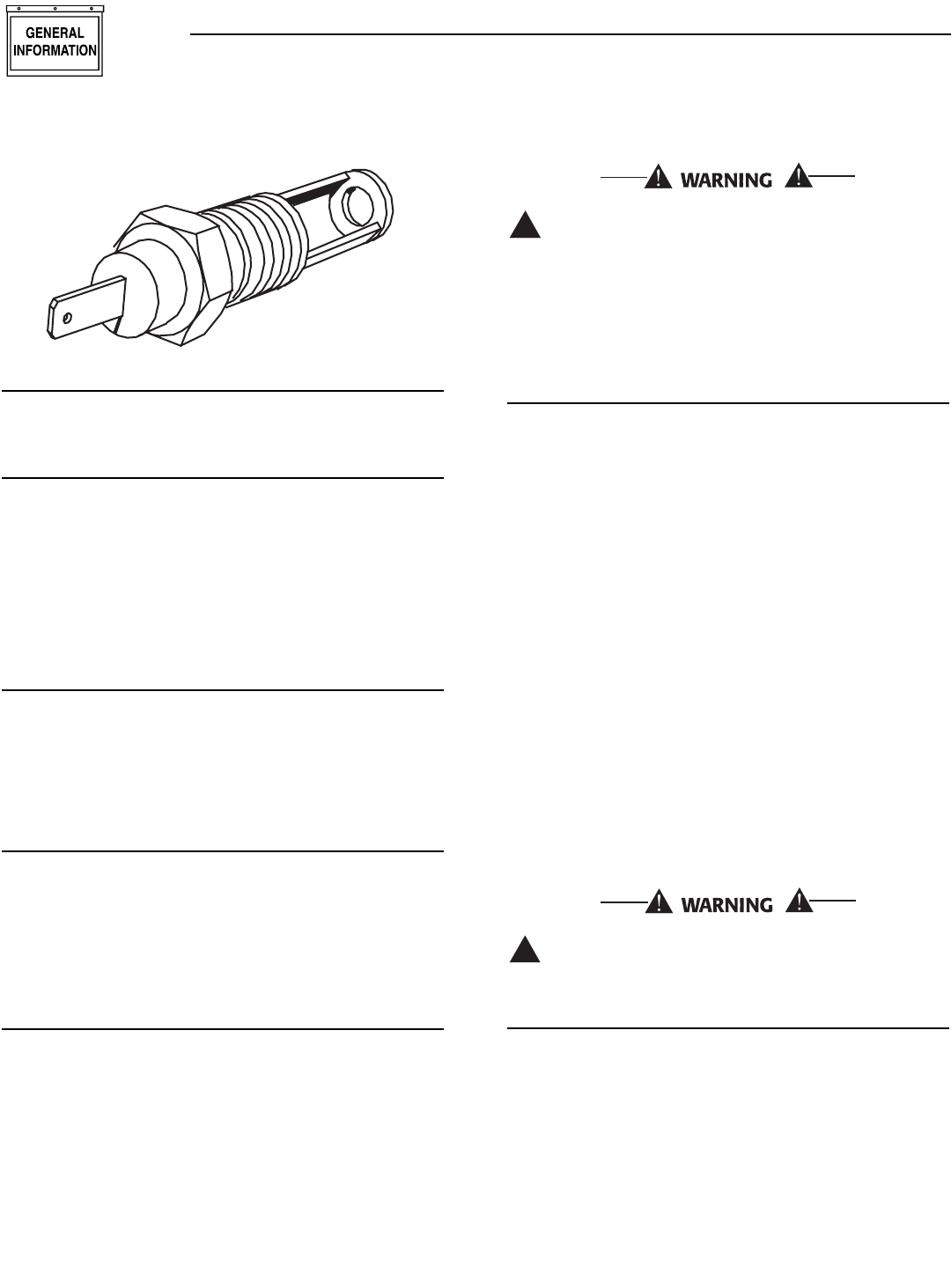
1.7.2 HIGH COOLANT TEMPERATURE
SWITCH
Normally open (N.O.) thermostatic switch has sens-
ing tip which is immersed in captive coolant. Should
coolant temperature exceed about 230°F (110°C), the
switch contacts close, which causes the engine to
shut down automatically (Figure 1.5).
Figure 1.5- High Coolant Temperature Switch
1.7.3 LOW COOLANT LEVEL SWITCH
Should engine coolant level drop below the level of
the high coolant temperature switch, it is possible for
the engine to overheat without automatic shutdown.
To prevent such overheating without automatic shut
down, the engine has a low coolant level sensor. If the
engine coolant drops too low, the engine automatical-
ly shuts down (Figure 1.6 on page 6).
!
Section 1 - General Information
Bryant Liquid-cooled 25 kW Generator
6 Bryant
Figure 1.6 - Low Coolant Level Sensor
1.7.4 OVERSPEED SHUTDOWN
Should AC frequency exceed about 72 Hz, circuit
board action will automatically shutdown the engine.
1.7.5 OVERCRANK SHUTDOWN
The engine control board uses a cyclic cranking
process when attempting to start the engine. The first
crank cycle is a 15-second crank followed by a seven-
second rest. This is followed by five more crank
cycles each with a seven second crank followed by a
seven-second rest.
If the engine fails to start after all six attempts, the start
attempt is stopped and the overcrank LED turns on.
1.7.6 LOW BATTERY
The engine control board continually monitors the
battery voltage and turns on the low battery LED if
the battery voltage falls below 12 VDC for one minute.
Low battery voltage is a non-latching alarm, which
will automatically clear if the battery voltage rises
above 12 VDC.
1.7.7 15A DC FUSE
This fuse is located inside the control panel. It pro-
tects the panel wiring and components from damag-
ing overload. The unit will not start or crank if the
fuse is blown. Replace the fuse with one of the same
size, type, and rating.
1.8 UNPACKING
1.8.1 UNPACKING PRECAUTIONS
Handle shipping cartons and crates with care. Use
care to avoid damage from dropping, bumping, colli-
sion, etc. Store and unpack cartons with the proper
side up, as noted on the shipping carton.
1.9 LIFTING THE GENERATOR
When lifting or hoisting equipment is used, be
careful not to touch overhead power lines. The
generators weight of more than 900 pounds
requires proper tools, equipment, and qualified
personnel to be used in all phases of handling
and unpacking.
1.10 SPECIFICATIONS
1.10.1 ENGINE
Make ......................................................................................Ford
Displacement ............................................153 inches3(2.5 liters)
Cylinder Arrangement......................................................4, in-line
Valve Arrangement................................................Overhead Cam
Firing Order........................................................................1-3-4-2
Number of Main Bearings............................................................5
Compression Ratio..........................................................9.37 to 1
No. of Teeth on Flywheel ........................................................164
Ignition Timing (Waste Spark System)
at 1800 rpm ..................................................36 degrees BTDC
Spark Plug Gap ............................................................0.044 inch
Recommended Spark Plugs ....................................0E96180241
Oil Pressure....................................................................30-50 psi
Crankcase Oil Capacity......................4.5 U.S. quarts (4.26 liters)
Recommended Engine Oil........................................SAE 15W-40
Type of Cooling System ..................Pressurized, closed recovery
Cooling Fan ..............................................................Pusher Type
Cooling System Capacity ......................2 U.S. gallons (7.6 liters)
Recommended Coolant ............Use a 50-50 mixture of ethylene
glycol base and deionized water.
Home standby control board assembly part
number 0E9704 must be used on 1800 rpm gen-
erators.
1.10.2 GENERATOR
Model ..................................................................ASPAS1BBL025
Rated Max. Cont. AC
Power Output (kW) ................................................................*25
Rated Voltage (volts) ........................................................120/240
No. of Rotor Poles ......................................................................4
Driven Speed of Rotor ..........................................................1800
Rotor Excitation System ........................Direct excited brush type
Type of Stator......................................................................4 Wire
Rotor Insulation ................................................................Class F
Stator Insulation................................................................Class H
!
!
Section 1 — General Information
Bryant Liquid-cooled 25 kW Generator
* Rated power of generator is subject to and limited by such
factors as ambient temperature, altitude, engine condition,
and other factors. Engine power will decrease about 2.5% for
each 1000 feet above 500 feet and will decrease an addition-
al 2.5% for each 10°F above 104°F. Maximum output power of
the generator is limited by maximum engine power.
1.11 FUEL CONSUMPTION
25 kW Models
Using Natural Gas ........................................441 cu. ft. per hour
Using LP Gas ..............................175 cubic ft.(4.8 gal.) per hour
Fuel pressure for a natural gas set up should be five
inches to 14 inches of water column (0.18 to 0.5
psi) at all load ranges.
Fuel pressure for an LP vapor set up should be 11
inches to 14 inches of water column (0.4 to 0.5
psi) at all load ranges.
NOTE:
Fuel consumption is given at rated maximum con-
tinuous power output when using natural gas
rated at 1000 Btu per cubic foot; or LP gas rated
2520 Btu per cubic foot. Actual fuel consumption
obtained may vary depending on such variables as
applied load, ambient temperature, engine condi-
tions and other environmental factors.
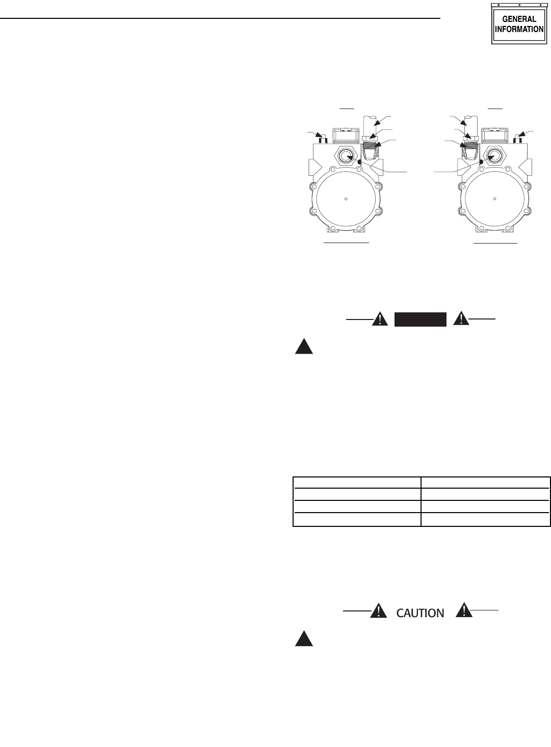
1.12 RECONFIGURING THE FUEL
SYSTEM FOR LP VAPOR
NOTE:
All models are configured for natural gas from the
factory.
To reconfigure the fuel system from NG to LP vapor,
follow these steps:
1. Turn the main gas supply off.
2. Remove the carburetor fuel hose from the outlet
port (Port 1) of the demand regulator (Figure
1.8).
3. Remove the brass hose fitting from the outlet port
(Port 1) of the demand regulator.
4. Remove pipe plug from Port 2.
5. Install brass hose fitting into Port 2.
6. Install pipe plug into Port 1.
7. Connect carburetor gas hose to brass fitting.
8. Tighten all clamps and plugs.
9. Make sure fuel supply is of the proper pressure
and type for configuration.
10. Move dip switch position 4 on the control board
to the off position (LP vapor, see Figure 3.2 and
Section 3.8).
11. Reverse the procedure to convert back to natural
gas.
Figure 1.8 — Reconfigure the Fuel System
NOTE:
Port 1 is for NG only and Port 2 is for LP vapor
only. No provision for dual fuel has been made.
Serious injury or damage may occur if not con-
figured properly. Please consult a dealer with
any questions.
1.13 ENGINE OIL RECOMMENDATIONS
The unit has been filled with 15W-40 engine oil at the
factory. Use a high-quality detergent oil classified “For
Service SJ or latest available.” Detergent oils keep the
engine cleaner and reduce carbon deposits. Use oil
having the following SAE viscosity rating, based on
the ambient temperature range anticipated before the
next oil change:
NOTE:
Synthetic oil is highly recommended when the
generator will be operating in ambient tempera-
tures which regularly exceed 90° F and/or fall
below 30° F.
Any attempt to crank or start the engine before
it has been properly serviced with the recom-
mended oil may result in an engine failure.
!
!
DANGER
NG FUEL SYSTEM LP FUEL SYSTEM
Port 1 Port 2
FUEL HOSE
BRASS HOSE
FITTING
OUT
PORT 2
PLUG
FUEL HOSE
BRASS HOSE
FITTING
FUEL INLET
PLUG
OUT
PORT 1
Section 1 — General Information
Bryant Liquid-cooled 25 kW Generator
Bryant 7
Temperature Oil Grade (Recommended)
Above 80° F (27° C) SAE 30W or 15W-40
32° to 80° F (-1° to 27° C) SAE 20W-20 or 15W-40
Below 32° F (0° C) SAE 10W or 15W-40
8 Bryant
1.14 COOLANT RECOMMENDATIONS
Use a mixture of half low silicate ethylene glycol base
anti-freeze and half deionized water. Cooling system
capacity is about 8 U.S. quarts (7.6 liters). Use only
deionized water and only low silicate anti-freeze. If
desired, add a high quality rust inhibitor to the rec-
ommended coolant mixture. When adding coolant,
always add the recommended 50-50 mixture.
Do not use any chromate base rust inhibitor
with ethylene glycol base anti-freeze or chromi-
umhydroxide (“green slime”) forms and will
cause overheating. Engines that have been
operated with a chromate base rust inhibitor
must be chemically cleaned before adding ethyl-
ene glycol base anti-freeze. Using any high sili-
cate anti-freeze boosters or additives will also
cause overheating. DO NOT use any soluble oil
inhibitor for this equipment.
1.15 BEFORE INSTALLATION
Before installing this equipment, check the ratings of
both the generator and the transfer switch. Read
“Emergency Isolation Method” and “Total Circuit
Isolation Method” in Sections 2.5 and 2.6.
The generator’s rated wattage/amperage capacity
must be adequate to handle all electrical loads that
the unit will power. It may be necessary to group the
critical (essential) loads together and wire them into
a separate “emergency” distribution panel.
This generator can be installed in conjunction with
an engineered transfer switch, if necessary.
The standard prepackaged transfer switch does not
have sensing or controlling circuit boards. Instead,
the generator control console houses a “Printed
Circuit Board Assembly”, which controls all phases
of operation, including engine start up and load
transfer.
2.1 STANDBY GENERATOR
INSTALLATION
Connecting this generator to an electrical sys-
tem normally supplied by an electric utility
shall be by means of a transfer switch, so as to
isolate the electric system from the utility distri-
bution system when the generator is operating.
Failure to isolate the electric system by these
means will result in damage to the generator
and may also result in injury or death to utility
workers due to backfeed of electrical energy.
If an open bottom is used, the engine-genera-
tor must be installed over non-combustible
materials and should be located such that com-
bustible materials are not capable of accumu-
lating under the generator set.
Only qualified, competent installation contractors or
electricians thoroughly familiar with applicable
codes, standards and regulations should install this
standby electric power system. The installation must
comply strictly with all codes, standards and regula-
tions pertaining to the installation.
After the system has been installed, do nothing
that might render the installation in noncompli-
ance with such codes, standards and regula-
tions.
NOTE:
For more information about the installation of a
standby system contact a dealer.
2.1.1 NFPA STANDARDS
The following published standards booklets pertain-
ing to standby electric systems are available form the
National Fire Protection Association (NFPA),
Batterymarch Park, Quincy, MA 02269:
NOTE:
It is essential to use the latest version of any stan-
dard to ensure correct and current information.
• NFPA No. 37, STATIONARY COMBUSTION
ENGINES AND GAS TURBINES.
• NFPA No. 76A, ESSENTIAL ELECTRICAL SYS-
TEMS FOR HEALTH CARE FACILITIES.
• NFPA No. 220, STANDARD TYPES OF BUILDING
CONSTRUCTION
• NFPA No. 68, GUIDE FOR EXPLOSION VENTING
• NFPA No. 70, NATIONAL ELECTRICAL CODE.
• NFPA No. 30, FLAMMABLE AND COMBUSTIBLE
LIQUIDS CODE.
• NFPA No. 10, INSTALLATION, MAINTENANCE AND
USE OF PORTABLE FIRE EXTINGUISHERS.
2.1.2 OTHER PUBLISHED STANDARDS
In addition to NFPA standards, the following infor-
mation pertaining to the installation and use of
standby electric systems is available:
NOTE:
It is essential to use the latest version of any stan-
dard to ensure correct and current information.
• Article X, NATIONAL BUILDING CODE, available
from the American Insurance Association, 85 John
Street, New York, N.Y. 10038.
!
DANGER
!
Section 2 — Installation
Bryant Liquid-cooled 25 kW Generator
Bryant 9
• AGRICULTURAL WIRING HANDBOOK, obtainable
from the Food and Energy Council, 909 University
Avenue, Columbia, MO, 65201.
• ASAE EP-364.2, INSTALLATION AND MAINTE-
NANCE OF FARM STANDBY ELECTRIC POWER,
available from the American Society of Agricultural
Engineers, 2950 Niles Road, St. Joseph, MI 49085.
• A52.1, AMERICAN NATIONAL STANDARD FOR
CHIMNEYS, FIREPLACES AND VENTING SYS-
TEMS, available from the American National
Standard Institute, 1430 Broadway, New York, N.Y.
10018.
2.2 GENERATOR LOCATION
Install the generator set, in its protective enclosure
outdoors, where adequate cooling and ventilating air
always is available. Consider these factors:
• Install the unit where air inlet and outlet openings
will not become obstructed by leaves, grass, snow,
etc. If prevailing winds will cause blowing or drift-
ing, consider using a windbreak to protect the unit.
• Install the generator on high ground where water
levels will not rise and endanger it.
• Allow sufficient room on all sides of the generator
for maintenance and servicing. Five feet allowance
of space is recommended on all sides. Local codes
may supercede this recommendation.
• Where strong prevailing winds blow from one
direction, face the generator air inlet openings into
the prevailing winds.
• Install the generator as close as possible to the
transfer switch. This reduces the length of wiring
and conduit.
• Install the generator as close as possible to the fuel
supply, to reduce the length of piping. HOWEVER,
REMEMBER THAT LAWS OR CODES MAY REG-
ULATE THE DISTANCE.
2.3 GENERATOR MOUNTING AND
SUPPORT
Retain the generator compartment to a concrete slab
with 1/4-inch masonry type anchor bolts. Be sure the
bolts are long enough to retain the compartment. The
slab should be at least six inches thick and should
extend beyond the enclosure to a distance of at least
three inches on all sides.
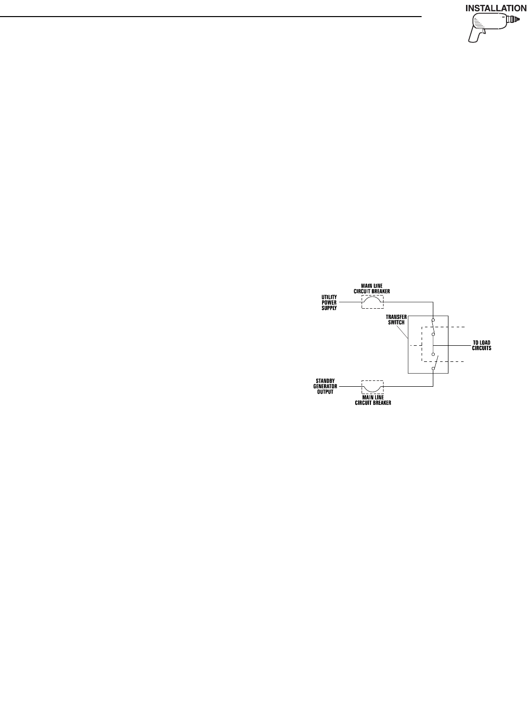
2.4 BASIC STANDBY ELECTRIC
SYSTEM
Figure 2.1 shows a schematic diagram of a basic
standby electric system. Both the UTILITY power
supply and the STANDBY GENERATOR output are
connected to an approved transfer switch. The trans-
fer switch is required by electrical code and serves
the following functions:
• Permits the LOAD circuits to be connected to only
one power supply at a time.
• Prevents electrical backfeed between the generator
and the UTILITY power circuits.
Notice that both the STANDBY and the UTILITY
power supplies to the transfer switch are protected
against overload by a main line circuit breaker.
Figure 2.1 – Basic Standby Electric System
NOTE:
Bryant recommends the use of a Bryant transfer
switch in conjunction with this generator.
2.5 EMERGENCY CIRCUIT ISOLATION
METHOD
This prevents overloading the generator by keeping
electrical loads below the wattage/amperage capacity
of the generator. If the generator is powering only crit-
ical loads, within the wattage/amperage capacity, dur-
ing utility power outages, consider using the emer-
gency circuit isolation method.
Critical electrical loads are grouped together and
wired into a separate “Emergency Distribution
Panel.” Load circuits powered by that panel are with-
in the wattage/amperage capacity of the generator set.
The transfer switch must meet the following require-
ments:
• It must have an ampere rating equal to the total
amperage rating of the emergency distribution
panel circuit.
• It must be installed between the building’s main
distribution panel and the emergency distribution
panel.
Section 2 — Installation
Bryant Liquid-cooled 25 kW Generator
10 Bryant
2.6 TOTAL CIRCUIT ISOLATION
METHOD
When a generator capable of powering all electrical
loads in the circuit is to be installed, the “Total
Circuit Isolation Method” may be used. The following
apply to the transfer switch in this type of system.
• Ampere rating of the transfer switch must equal
the ampere rating of the normal incoming utility
service.
• The transfer switch is installed between the utility
service entrance and the building distribution
panel.
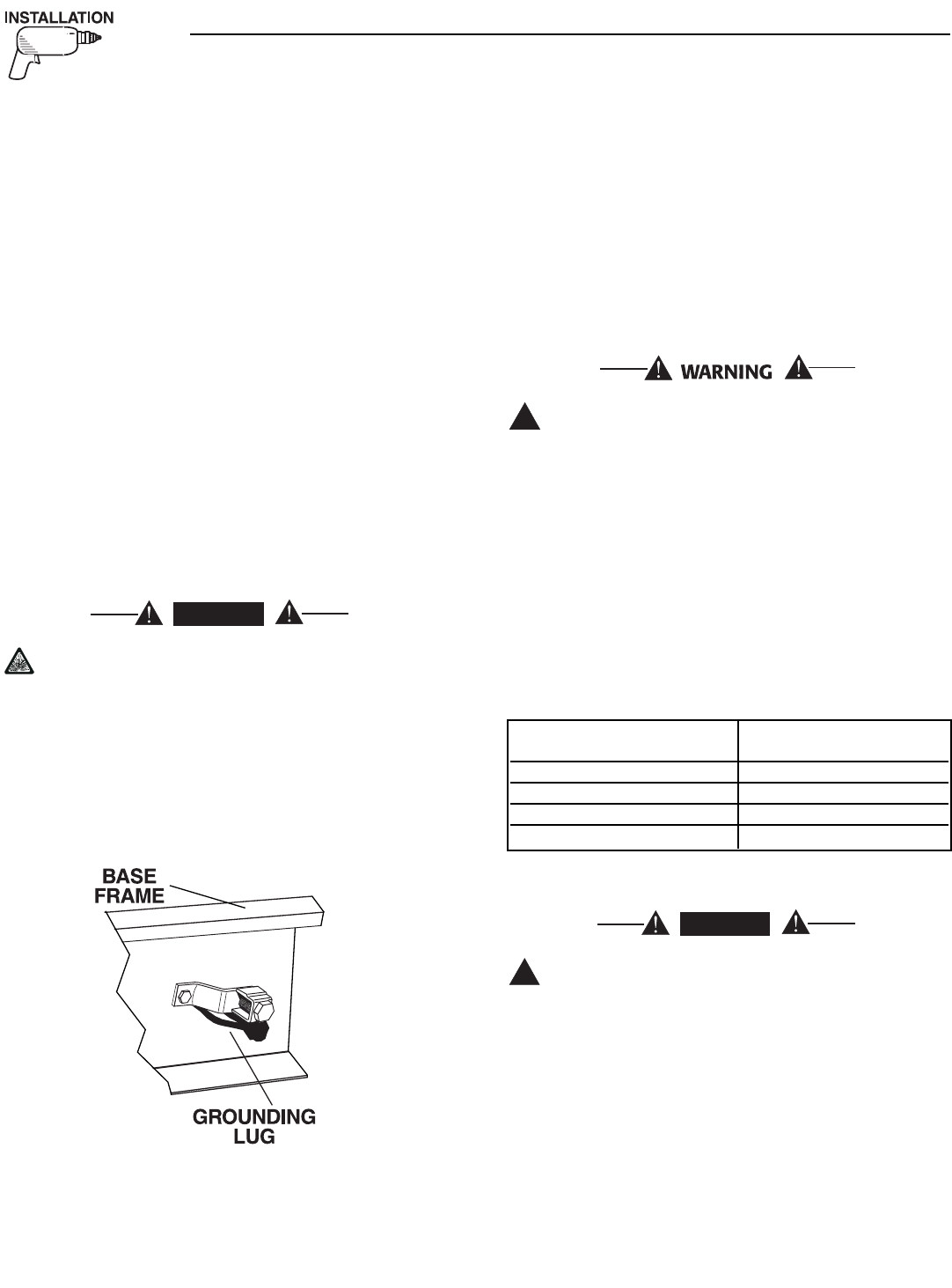
2.7 GROUNDING THE GENERATOR
The National Electrical Code requires the frame and
external electrically conductive parts of this equip-
ment to be properly connected to an approved earth
ground and/or grounding rods. For that purpose, a
GROUND LUG (Figure 2.2) is provided on the gener-
ator mounting base. Consult a qualified electrician
for grounding requirements in the area. Grounding
procedures must meet local regulations.
Do not connect the ground wire to any pipe
that carries a flammable or explosive substance
– FIRE or an EXPLOSION may result.
Proper grounding helps protect personnel against
electrical shock in the event of a ground fault condi-
tion in the generator or in connected electrical
devices. In addition, grounding helps dissipate static
electricity that often builds up in ungrounded devices.
Figure 2.2 – Generator Grounding Lug (typical)
2.8 GENERATOR AC NEUTRAL
CONNECTIONS
Bryant uses an UNGROUNDED AC neutral.
Grounding is recommended only at the main service
entrance. If the neutral wire is grounded and one of
the phase loads becomes grounded, the excessive
current opens the load circuit breaker or collapses
the generator field. The actual result depends on the
electrical characteristics of the particular installed
generator.
Failure to connect the generator neutral prop-
erly will result in unbalanced line-to-neutral
voltages. Resulting high voltages will cause
equipment damage.
2.9 TRANSFER SWITCH SIGNAL
CONNECTIONS
It is necessary to connect the control wires between
the generator and the transfer switch.
Control system interconnections consist of N1, N2,
T1, T2 and leads 23 and 194. Control system inter-
connection leads must be run in a conduit that is sep-
arate from the AC power lead. Recommended wire
gauge sizes for this wiring depends on the length of
the wire, as recommended below:
2.10 BATTERY INSTALLATION
Standby generators installed with automatic
transfer switches will crank and start automati-
cally when NORMAL (UTILITY) source voltage is
removed or is below an acceptable preset level.
To prevent such automatic start-up and possible
injury to personnel, do not connect battery
cables until certain that normal source voltage
at the transfer switch is correct and the system
is ready to be placed into operation. Ensure
that the 5A and 15A fuses in the control panel
are removed when connecting or disconnecting
battery cables.
!
DANGER
!
DANGER
Section 2 — Installation
Bryant Liquid-cooled 25 kW Generator
MAXIMUM WIRE LENGTH RECOMMENDED WIRE
SIZE
460 feet (140m) No. 18 AWG.
461 to 730 feet (223m) No. 16 AWG.
731 to 1,160 feet (354m) No. 14 AWG.
1,161 to 1,185 feet (565m) No. 12 AWG.
Bryant 11
Storage batteries give off explosive hydrogen
gas. This gas can form an explosive mixture
around the battery for several hours after
charging. The slightest spark can ignite the gas
and cause an explosion. Such an explosion can
shatter the battery and cause blindness or
other injury. Any area that houses a storage
battery must be properly ventilated. Do not
allow smoking, open flame, sparks or any spark
producing tools or equipment near the battery.
Battery electrolyte fluid is an extremely corro-
sive sulfuric acid solution that can cause severe
burns. Do not permit fluid to contact eyes, skin,
clothing, painted surfaces, etc. Wear protective
goggles, protective clothing and gloves when
handling a battery. If fluid is spilled, flush the
affected area immediately with clear water.
Do not dispose of the battery in a fire. The bat-
tery is capable of exploding.
Do not open or mutilate the battery. Released
electrolyte can be toxic and harmful to the skin
and eyes.
The battery represents a risk of high short cir-
cuit current. When working on the battery,
always remove watches, rings or other metal
objects, and only use tools that have insulated
handles.
2.10.1 VENTED BATTERIES
The electrolyte is a dilute sulfuric acid that is
harmful to the skin and eyes. It is electrically
conductive and corrosive. The following proce-
dures are to be observed:
• Wear full eye protection and protective clothing,
• Where electrolyte contacts the skin, wash it off
immediately with water,
• Where electrolyte contacts the eyes, flush thor-
oughly and immediately with water and seek med-
ical attention, and
• Spilled electrolyte is to be washed down with an
acid-neutralizing agent. A common practice is to
use a solution of one pound (500 grams) bicarbon-
ate of soda to one gallon (4 liters) of water. The
bicarbonate of soda solution is to be added until
the evidence of reaction (foaming) has ceased. The
resulting liquid is to be flushed with water and the
area dried.
Lead acid batteries present a risk of fire
because they generate hydrogen gas. The fol-
lowing procedure are to be followed:
• DO NOT SMOKE when near batteries,
• DO NOT cause flame or spark in battery area, and
• Discharge static electricity from body before touch-
ing batteries by first touching a grounded metal
surface.
Servicing of batteries is to be performed or super-
vised by personnel knowledgeable of batteries and
the required precautions. Keep unauthorized person-
nel away from batteries.
The recommended battery is Group 26, 525 CCA/75
AH minimum at 0° F (-17.8° C). All batteries must be
at 100 percent state-of-charge before they are
installed on the generator.
When using maintenance-free batteries, it is not nec-
essary to check the specific gravity or electrolyte level.
Have these procedures performed at the intervals
specified in Section 4, “Maintenance.” A negative
ground system is used. Battery connections are
shown on the wiring diagrams. Make sure all batter-
ies are correctly connected and terminals are tight.
Observe battery polarity when connecting batteries to
the generator set.
NOTE:
Damage will result if the battery connections are
made in reverse.
2.11 PREPARATION BEFORE START-UP
The instructions in this section assume that the
standby generator has been properly installed, serv-
iced, tested, adjusted and otherwise prepared for use
by a competent, qualified installation contractor. Be
sure to read the “Safety Rules” on pages 2 and 3, as
well as all other safety information in this manual,
before attempting to operate this (and related) equip-
ment.
2.11.1 PRIOR TO INITIAL START-UP
Prior to initially starting the generator, it must
be properly prepared for use. Any attempt to
crank or start the engine before it has been
properly serviced with the recommended types
and quantities of engine fluids (oil, coolant,
fuel, etc.) may result in an engine failure.
Before starting the generator for the first time, the
installer must complete the following procedures. For
follow-up maintenance information and/or service
intervals, please refer to Section 4, “Maintenance.”
!
!
!
!
Section 2 — Installation
Bryant Liquid-cooled 25 kW Generator
12 Bryant
Section 3 - Operation
Bryant Liquid-cooled 25 kW Generator
2.11.2 TRANSFER SWITCH
If this generator is used to supply power to any elec-
trical system normally powered by an electric utility,
the National Electrical Code requires that a transfer
switch be installed. The transfer switch prevents elec-
trical backfeed between two different electrical sys-
tems, (for additional information, see the applicable
transfer switch manual for this unit). The transfer
switch, as well as the generator and other standby
components, must be properly located and mounted
in strict compliance with applicable codes, standards
and regulations.
2.11.3 FUEL SYSTEM
Make sure the fuel supply system to the generator (a)
delivers the correct fuel at the correct pressure and
volume and, (b) is properly purged and leak tested
according to code. No fuel leakage is permitted.
2.11.4 GENERATOR SET LUBRICATION
Check the engine crankcase oil level before operating
and add oil to the proper level – the dipstick “FULL”
mark. Never operate the engine with the oil level
below the dipstick “ADD” mark. See “Specifications”
and “Engine Oil Recommendations”.
NOTE:
This engine is shipped from the manufacturer
with 15W-40 oil. This oil should be changed after
30 hours of operation.
2.11.5 ENGINE COOLANT
Have the engine cooling system properly filled with
the recommended coolant mixture. Check the system
for leaks and other problems. See “Specifications”
and “Coolant”.
2.11.6 BELT TENSION
Check the engine fan belt tension and condition prior
to placing the unit into service and at recommended
intervals. Belt tension is correct when a force of
approximately 22 pounds (10 kg), applied midway
between pulleys, deflects the belt about 3/8- to 5/8-
inches (10 to 16 mm).
2.11.7 ELECTRICAL SYSTEM
Make sure the generator is properly connected to an
approved earth ground and/or ground rod.
Make sure the generator battery is fully charged,
properly installed and interconnected, and ready for
use.
Check to ensure that there are no loose electrical con-
nections. Restrain any loose wires to keep them clear
of any moving generator set components.
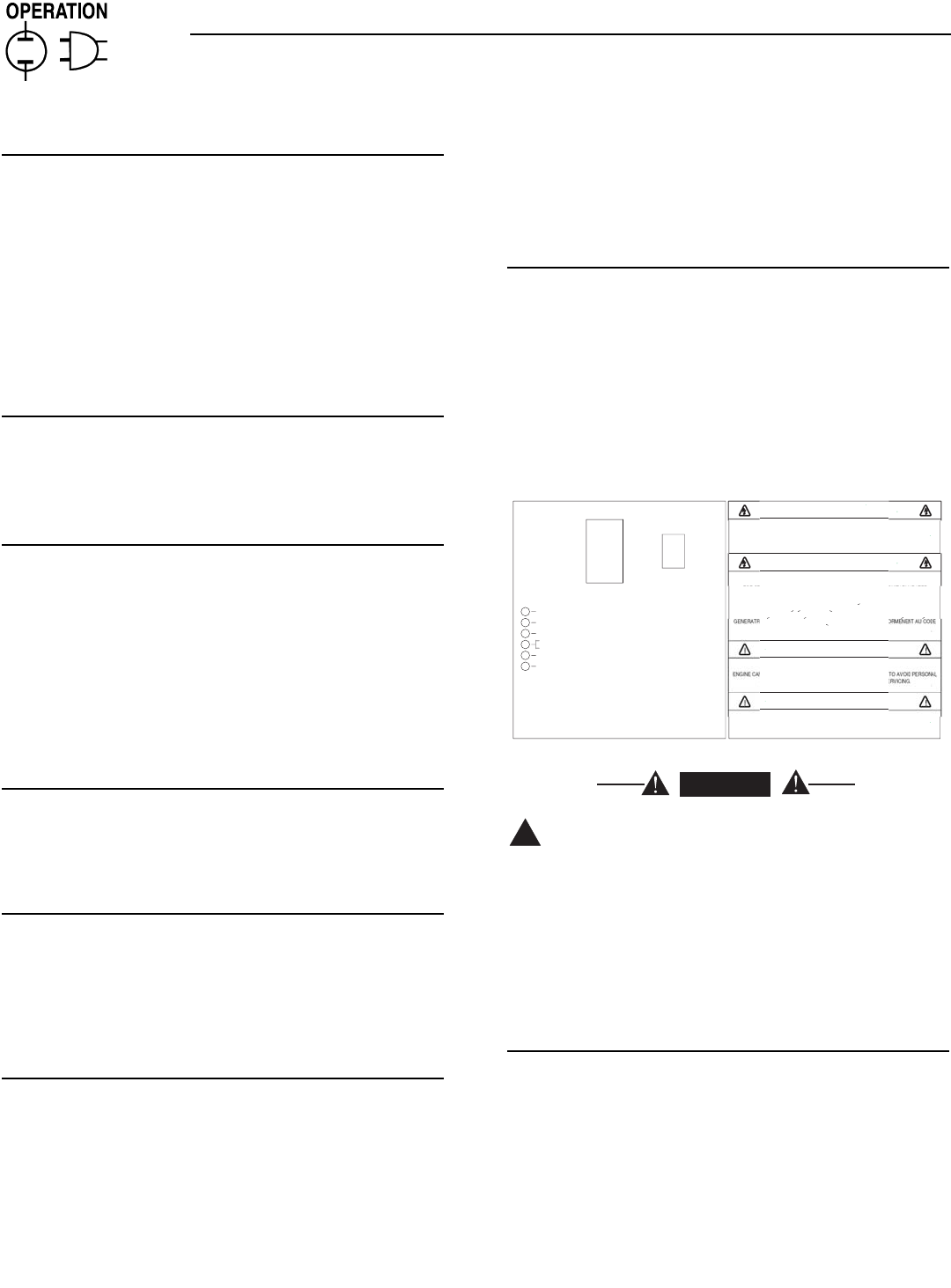
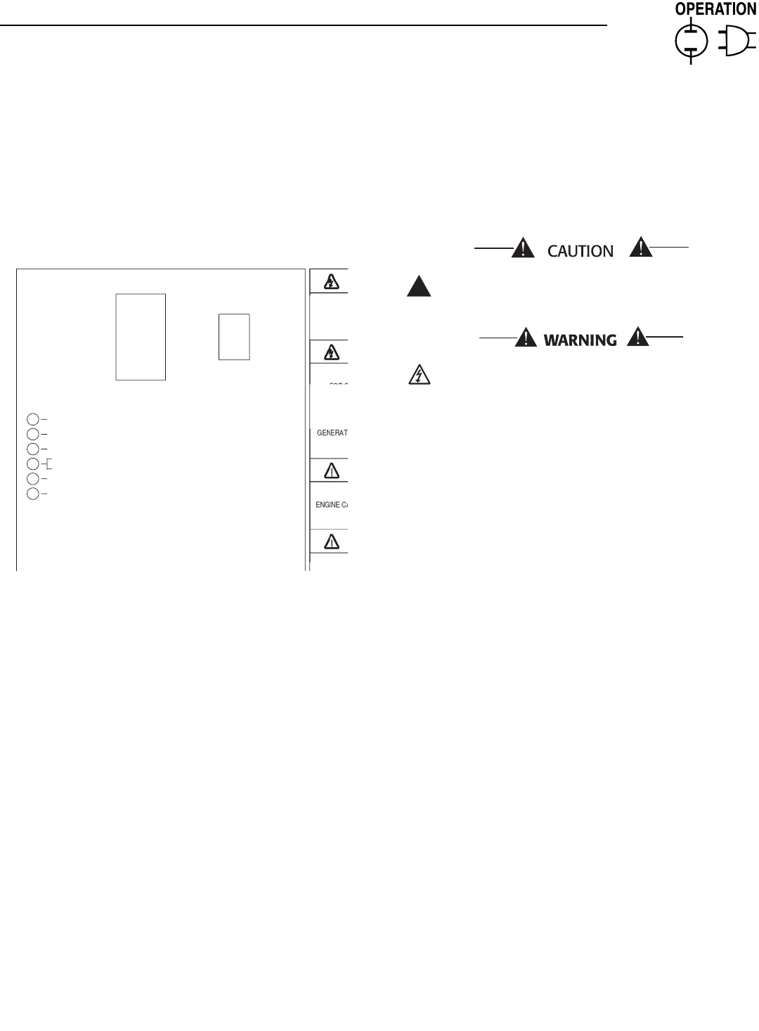
3.1 CONTROL CONSOLE
COMPONENTS
The components of a home standby generator control
console (Figure 3.1) are as follows:
3.1.1 AUTO/OFF/MANUAL SWITCH
Use this three-position switch as follows:
• Set the switch to AUTO for fully automatic opera-
tion. See “Automatic Operation” (Section 3.5).
• Set switch to MANUAL position to crank and start
the generator engine.
• Set switch to OFF position to shut down an oper-
ating engine. With OFF selected, operation will not
be possible.
Figure 3.1 - Home Standby Generator Panel
With switch set to AUTO, engine can crank and
start suddenly without warning. Such automat-
ic start up normally occurs when utility source
voltage drops below a pre-set level. To prevent
possible injury that might be caused by such
sudden starts, set AUTO/OFF/ MANUAL switch
to OFF before working on or around the unit.
Then, place a “DO NOT OPERATE” tag on con-
trol console.
3.1.2 FAULT INDICATOR LEDS
(SEE CHART ON PAGE 13)
These LEDs turn ON when one or more of the follow-
ing engine faults occurs and the engine shuts down.
• Low Oil Pressure
• Overcrank
• Low Battery
• Overspeed/Engine Speed Signal Fault
• High Coolant Temperature/Low Coolant Level
See Section 1.7 for further explanation of engine pro-
tection functions.
!
DANGER
FOR STAND-BY SERVICE CONNECT OUTPUT OF GENERATOR TO SUITABLY RATED
TRANSFER SWITCH IN ACCORDANCE WITH CANADIAN ELECTRICAL CODE
,
PART I
.
ATTENTION: POUR L'ALIMENTATION DE RESERVE, CONNECTER LA SORTIE DE LA
I
CE A UN COMMUTATEUR DE CALIBRE APPROPRIE
,
CONF
O
CANADIEN DE L'ECTRICITE
,
PREMIERE PARTIE
.
RI
S
K
O
F ELE
C
TRI
C
AL
S
H
OC
K. D
O
N
O
T REM
O
VE
CO
VER. N
O
US
ER
S
ERVI
C
EABLE
PARTS INSIDE. REFER SERVICING TO
Q
UALIFIED SERVICE PERSONNEL
.
THI
S
EMER
G
EN
C
Y P
O
WER
S
Y
S
TEM I
S
DE
S
I
G
NED EX
C
L
US
IVELY F
O
R
OU
TD
OO
R IN
S
TALLATI
O
N
O
NLY
!
N
A
U
T
O
MATI
C
ALLY
S
TART AT ANYTIME WITH
OU
T N
O
TI
C
E.
T
IN
JU
RY REM
O
VE NE
G
ATIVE BATTERY
C
ABLE PRI
O
R T
O
SE
L
O
W
COO
LANT LEVE
L
HI
COO
LANT TEMPERAT
U
R
E
FLA
S
HIN
G
G
REEN LED = N
O
U
TILITY
S
EN
SE
5
FLA
S
HIN
G
RED LED'
S
= EXER
C
I
S
ER N
O
T
S
ET
(
IN AUTO MODE ONLY
)
SOLID GREEN LED = SYSTEM READY, UTILITY POWER O
N
US
E
O
F
S
YNTHETI
C
O
IL I
S
RE
CO
MMENDE
D
(
SEE OWNER'S MANUAL FOR COMPLETE DETAILS
)
LED INDI
C
AT
O
R
S:
RED LED'
S
= INDIVID
U
AL FA
U
L
T
O
VER
C
RAN
K
S
Y
S
TEM READ
Y
L
O
W BATTER
Y
L
O
W
O
IL PRE
SSU
R
E
O
VER
S
PEE
D
O
F
F
MAN
U
A
L
A
U
T
O
START
,
RUN THROUGH THE EXERCISE
C
Y
C
LE AND
S
H
U
TD
O
WN
.
TIME
S
E
T
EXER
C
I
SE
T
O
A
U
T
O
P
OS
ITI
O
N
.
S
WIT
C
H IN "
O
N" P
OS
ITI
O
N F
OR
1
)
PLACE AUTO/OFF/MANUAL SWITC
H
2
)
HOLD "SET EXERCISE TIME
"
T
O
S
ET EXER
C
I
S
ER TIM
E
1
0
S
E
CO
ND
S
. THEN THE
U
NIT WILL
THE EXER
C
I
S
ER I
S
N
O
W
S
ET. ALL
FIVE RED LED'
S
WILL FLA
S
H F
OR
THREE
S
E
CO
ND
S
AND RELEA
S
E
.
ON
WARNIN
G
C
A
U
TI
ON
WARNIN
G
0
F
0653
O
F
F
C
A
U
TI
ON

Bryant 13
3.1.3 15 AMP FUSE
This fuse protects the control console’s DC control
circuit against electrical overload and is located inside
the control panel. If the fuse has melted open because
of an overload, engine cranking and startup cannot
occur. If the fuse needs to be replaced, use only an
identical 15-amp replacement fuse (type ATO).
3.1.4 5 AMP FUSE
This fuse protects the battery charger against electri-
cal overload and is located inside the control panel. If
the fuse needs to be replaced, use only an identical 5-
amp replacement fuse (type ATO).
NOTE:
This fuse will not remove the + battery input
power from the PCB when it opens. This means
the exercise timer will not be reset.
3.1.5 SET EXERCISE TIME SWITCH
This switch allows programming the generator to
start and exercise automatically. “See Weekly
Exercise Cycle.”
3.1.6 SYSTEM READY LED
The System Ready LED (green) has two main pro-
poses. First, the LED will be ON when the
AUTO/OFF/MANUAL switch is in the AUTO position,
utility is present, and there are no system alarms.
This ON state indicates the system is fully ready for
automatic operation.
The system ready LED will be OFF when the switch
is in the manual or OFF positions.
The system ready LED is also used to indicate the
presence of utility sensing at the PCB when the switch
is either in the AUTO or MANUAL modes. The LED
will flash at the rate of 1/2 second on, 1/2 second off
if the utility sensing level is below the transfer back
threshold.
This secondary function is only available with dip
switch two in the OFF position (ATS - automatic
transfer switch application).
Section 3 - Operation
Bryant Liquid-cooled 25 kW Generator
Condition System Low Low High Over Over Switch Position
Ready (Green) Bat (Red) Oil (Red) Temp (Red) Speed (Red) Crank (Red) Manual Auto Off
Generator Switch is OFF X OFF OFF OFF OFF O
in the OFF Mode.
System Ready for ON X OFF OFF OFF OFF O
Automatic Start
Generator Switch is OFF X OFF OFF OFF OFF O
in the MANUAL Mode
Weekly Exerciser X Flashing Flashing Flashing Flashing Flashing O O O
is not set (-----------------------------------1 sec rate---------------------------------------)
Battery Voltage <12V X ON OOO
for >1 minute (Non-latching)
Battery Voltage <6V X ON OO
Unit Shutdown due OFF X ON O O
to Low Oil Pressure
Unit Shutdown due OFF X ON O O
to High Temperature
Unit Shutdown due OFF X ON O O
to Engine Overspeed
Unit Failed to Start OFF X ON O O
during it’s Crank Cycle
Utility Voltage is Flashing X OO
<45% of Nominal 1 sec rate
Engine Speed Signal Fault OFF X Flashing O O
Control Board Dip Switch OFF X The five RED LED’s will turn on one at a time O O O
is in wrong position.
X = indicates that the LED can be ON or OFF depending on the operating conditions.
14 Bryant
3.2 MANUAL TRANSFER AND
START-UP
To transfer electrical loads to the Standby (EMER-
GENCY) power source side and start the engine man-
ually, refer to the Owner’s Manual of the particular
transfer switch.
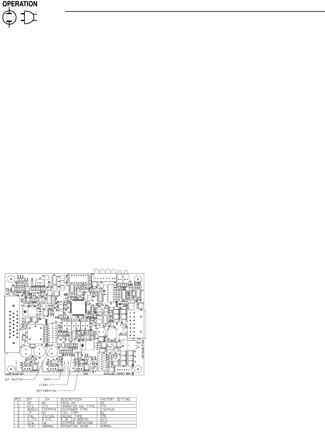
3.3 ENGINE GOVERNOR
ADJUSTMENTS
Engine speed governing is also controlled by the
engine control board. The engine governor has been
set by the factory during final testing of the generator
and should not be adjusted.
If, however, adjustments are necessary, the following
procedure should be followed (Figure 3.2 and Section
3.8):
1. Move dip switch 8 to the test mode (OFF posi-
tion).
2. Set all three potentiometers (pots) fully counter-
clockwise.
3. Under no load condition, increase the GAIN pot
as much as possible without causing instability.
4. Apply 1/4, 1/2, 3/4 and full load to the unit.
Decrease the GAIN pot if there is instability at any
load point.
5. Under full load condition, increase the stability
pot until the unit returns to 60 Hertz (or 50 Hertz
in 50 Hertz applications).
Figure 3.2 — Engine Governor Adjustment
6. Reduce load to 3/4, 1/2, 1/4 and no load.
Decrease the stability pot if there is instability at
any load point.
7. Adjust differential pot to make the recovery to
load changes even faster and minimize load
change undershoot and overshoot. If it is set too
high, it may introduce oscillations at some load.
It can be set to zero (full CCW) if a small amount
causes oscillations at some load.
3.4 RETRANSFER AND SHUTDOWN
When utility power source voltage has been restored,
electrical loads may be transferred back to that
source and the generator can be shut down as fol-
lows:
• Verify that utility power supply voltage to the trans-
fer switch has been positively turned Off, using
whatever means provided (such as utility main line
circuit breaker).
• Set the generator’s main circuit breaker to its Off
or Open position.
• Let the generator engine run at no-load for a few
minutes, to stabilize internal unit temperatures.
• On the generator console, set the Auto/Off/ Manual
switch to Off. Wait for engine to come to a complete
stop.
• For transfer to utility position, refer to the Owner’s
Manual of the particular transfer switch.
• Turn on the utility power supply to the transfer
switch, using whatever means provided (such as a
utility main line circuit breaker). The utility power
source now powers the loads.
3.5 AUTOMATIC OPERATION
To set the system for fully automatic operation, pro-
ceed as follows:
• Check that load circuits are connected to the
utility power supply.
• Set the AUTO/OFF/MANUAL switch to its AUTO
position.
• Set the generator main circuit breaker to its ON or
CLOSED position.
3.6 WEEKLY EXERCISE CYCLE
The engine control board will start and run the gen-
erator once every seven days for approximately 12
minutes. If utility should fail during this exercise
period, the engine control board will transfer the load
to the generator output and continue to run until util-
ity returns.
On the day, and at the time of day chosen for the gen-
erator to exercise, set the weekly exercise cycle as fol-
lows:
1. Place the AUTO/OFF/MANUAL switch in the auto
position (Figure 3.3).
Section 3 - Operation
Bryant Liquid-cooled 25 kW Generator
Bryant 15
Section 3 - Operation
Bryant Liquid-cooled 25 kW Generator
2. Press and hold the “Set Exercise” switch for five
seconds, then release.
At this time all five red LEDs will flash for approxi-
mately 10 seconds, then the engine will start and run
for it’s 12 minute exercise period, then shut down.
The generator will now start and run each week at the
same time.
Figure 3.3 - “Set Exercise Time” Switch
If DC power to the control board is lost, the weekly
exercise setting will be lost. This is indicated by all
five red LEDs continually flashing. In this state the
generator will still start and run in manual mode, or
automatically start and run if utility is lost while in
Auto mode, but it will not perform a weekly exercise
cycle.
If a failure occurs while running in this mode, the five
red LEDs will stop flashing, the individual fault LED
will turn on and the engine will shut down. Once the
AUTO/OFF/MANUAL switch has been switch to OFF,
the individual fault LED will turn OFF and the five
red LEDs will begin flashing to show exercise has still
not been set.
3.7 CONTROL BOARD DIP SWITCH
SETTINGS
Located on the control board is an eight position DIP
switch (see Figure 3.2). The eight different switches,
are used to configure the control board for the spe-
cific engine and governor being used and are pre-set
at the factory.
If the DIP switch settings are not set correctly,
the generator may not start or operate correct-
ly.
240 VAC can be present within the control
panel.
If it is necessary to select an alternate switch position,
move the AUTO/OFF/MANUAL switch to the OFF
position. Remove the 5 amp and 15 amp fuses in the
generator control panel. Move the DIP switch position
that needs to be changed to its new position. Wait five
seconds, then re-install the 5 and 15 amp fuses.
The ON position is marked on the switch and the fac-
tory settings are also shown in Figure 3.3.
Switch Position 1 — Selects the generator alternator
output frequency and is factory pre-set for 60 Hz.
Switch Position 2 — Selects the type of transfer
switch and is factory pre-set for the prepackaged
transfer switch.
Switch Position 3 — Selects the type of governor
control used and is factory pre-set for stepper motor
control.
Switch Position 4 — Selects the type of fuel being
used and is factory pre-set for natural gas (NG).
Switch Position 5 — Selects the engine displacement
and is factory pre-set for a 2.5 liter (2.5L) engine.
Switch Position 6 — Selects the number of engine
cylinders and is factory pre-set for four cylinders.
Switch Position 7 — Selects the direction of rotation
of the governor stepper motor and is factory pre-set
for CCW rotation (rotation is observed looking at the
stepper shaft as it move from closed throttle to open
throttle).
Switch Position 8 — Selects whether the control is
in the Normal Mode of operation or Test Mode. In the
Normal Mode of operation, pre-determined governor
gains are used and the gain trimpots on the control
board (Gain, Stability, and Differential) are not active
and have no effect on the gains. In Test Mode the gain
trimpots are active and can be adjusted. See Section
3.4.
!
FOR ST
TRAN
S
ATTEN
RI
S
K
O
P
L
O
W
COO
LANT LEVE
L
HI
COO
LANT TEMPERAT
U
R
E
FLA
S
HIN
G
G
REEN LED = N
O
U
TILITY
S
EN
SE
5
FLA
S
HIN
G
RED LED'
S
= EXER
C
I
S
ER N
O
T
S
E
T
(
IN AUTO MODE ONLY
)
SOLID GREEN LED = SYSTEM READY, UTILITY POWER O
N
(
SEE OWNER'S MANUAL FOR COMPLETE DETAILS
)
LED INDI
C
AT
O
R
S:
RED LED'
S
= INDIVID
U
AL FA
U
L
T
O
VER
C
RAN
K
S
Y
S
TEM READ
Y
L
O
W BATTER
Y
L
O
W
O
IL PRE
SSU
R
E
O
VER
S
PEE
D
O
F
F
MAN
U
A
L
A
U
T
O
START
,
RUN THROUGH THE EXERCISE
C
Y
C
LE AND
S
H
U
TD
O
WN
.
TIME
S
E
T
EXER
C
I
SE
T
O
A
U
T
O
P
OS
ITI
O
N
.
S
WIT
C
H IN "
O
N" P
OS
ITI
O
N F
OR
1
)
PLACE AUTO/OFF/MANUAL SWITC
H
2
)
HOLD "SET EXERCISE TIME
"
T
O
S
ET EXER
C
I
S
ER TIM
E
1
0
S
E
CO
ND
S
. THEN THE
U
NIT WILL
THE EXER
C
I
S
ER I
S
N
O
W
S
ET. ALL
FIVE RED LED'
S
WILL FLA
S
H F
OR
THREE
S
E
CO
ND
S
AND RELEA
S
E
.
ON
0
F
0653
O
F
F
16 Bryant
Section 4 — Maintenance
Bryant Liquid-cooled 25 kW Generator
4.1 MAINTENANCE PERFORMED BY
AUTHORIZED SERVICE FACILITIES
A. EVERY THREE MONTHS
1. Check battery condition.
2. Inspect and test fuel system.
3. Check transfer switch.
4. Inspect exhaust system.
5. Check engine ignition system.
6. Check fan belts.
B. ONCE EVERY SIX MONTHS
1. Test Engine Safety Devices (low oil pressure, low
coolant level, high coolant temperature).
C. ONCE ANNUALLY
1. Test engine governor; adjust or repair, if needed.
2. Clean, inspect generator.
3. Flush cooling system.
D. FIRST 100 OPERATING HOURS
1. Change engine oil and oil filter. After initial
change, service engine oil and filter at 150 oper-
ating hours or six months, whichever comes first.
2. Retorque cylinder head (see torque specs).
3. Retorque intake and exhaust manifold (see
torque specs).
E. EVERY 500 OPERATING HOURS
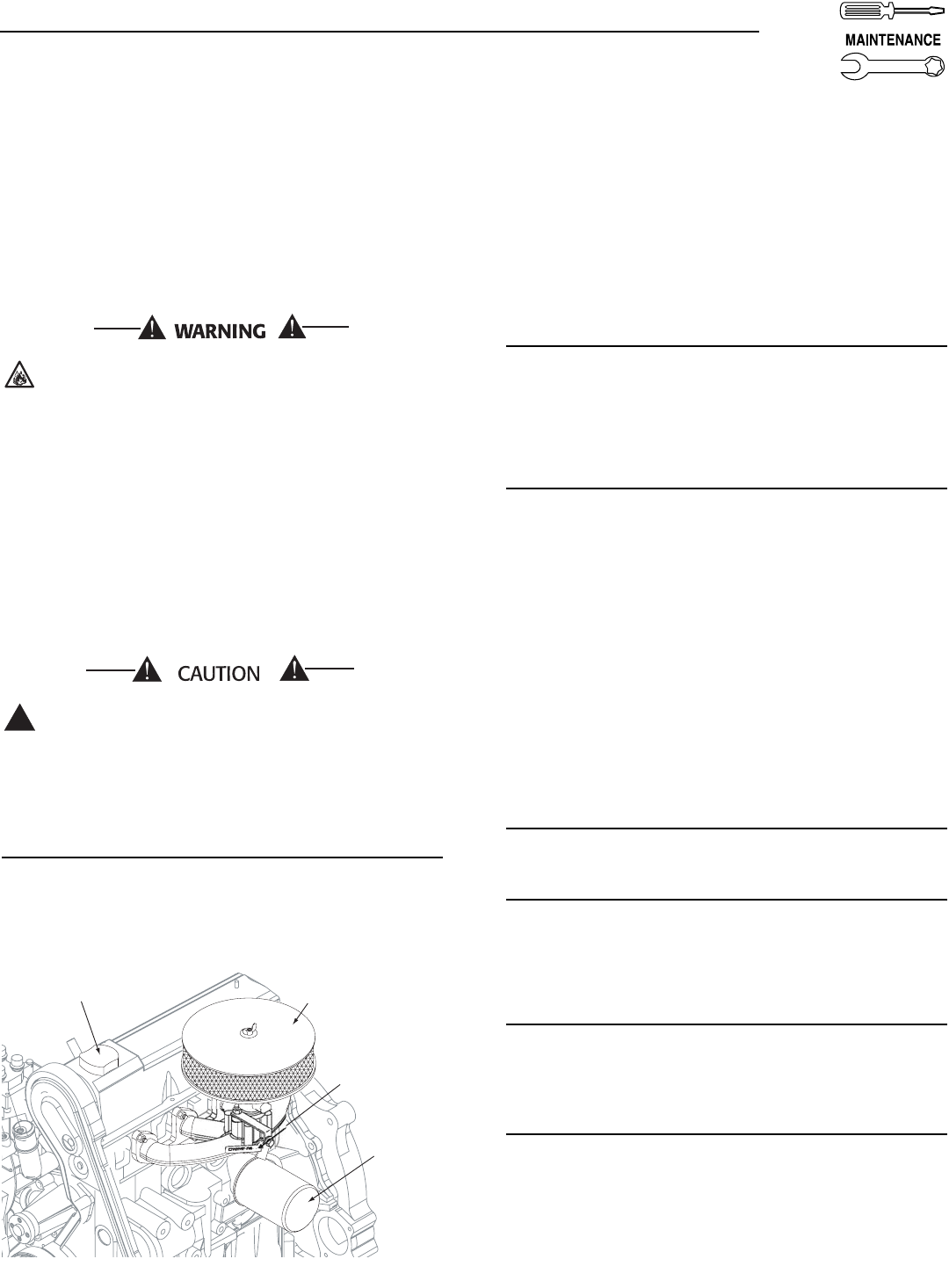
1. Service air cleaner.
2. Check starter.
3. Check engine DC alternator.
F. EVERY 800 OPERATING HOURS
1. Retorque cylinder head (see torque specs).
2. Retorque intake and exhaust manifold (see
torque specs).
3. Check engine compression.
4. Check valve clearance.
4.2 EXHAUST MANIFOLD PROCEDURE
1. If necessary, clean gasket surfaces on exhaust
manifold and cylinder head.
2. Install exhaust manifold and exhaust manifold
gasket.
3. Install fasteners.
NOTE:
Exhaust manifold fasteners must be tightened in
two stages.
4. Tighten fasteners to 20-30 N-m (15-22 lb-ft) dur-
ing the first stage.
5. Retighten fasteners to 60-80 N-m (44-59 lb-ft)
during the second stage.
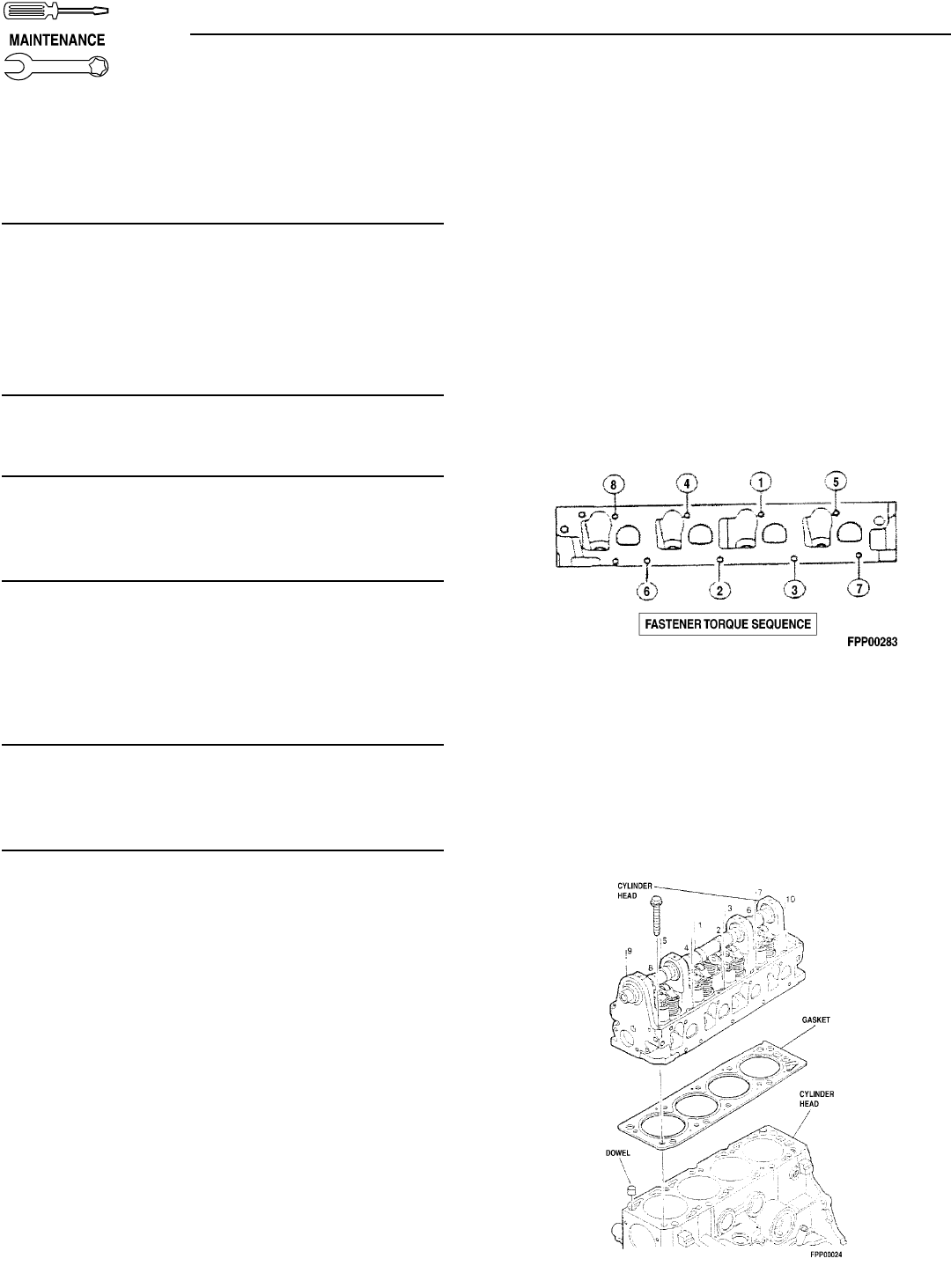
4.3 INTAKE MANIFOLD PROCEDURE
1. Clean and inspect the mounting surfaces of the
intake manifold and the cylinder head. Both sur-
faces must be clean and flat (Figure 4.1).
2. Clean and lightly oil the manifold bolt/stud
threads.
3. Install a new lower intake manifold gasket.
4. Position the lower intake manifold to the cylinder
head.
5. Install retaining bolts/studs finger tight.
6. Tighten all bolts/studs to specifications in the
tightening sequence shown:
• First pass = 7=10 N-m (5-7 lb-ft).
• Final pass = 26-38 N-m (19-28 lb-ft).
Figure 4.1 — Intake Manifold Installation
4.4 CYLINDER HEAD PROCEDURE
1. Position head gasket on the block (Figure 4.2).
2. Position cylinder head to cylinder block.
3. Install 10 cylinder head bolts in numerical
sequence. Tighten to 70 N-m (52 lb-ft) in
sequence. Retighten to 70 N-m (52 lb-ft) in
sequence. Then turn all head bolts an additional
90 - 100 degrees in sequence.
Figure 4.2 — Cylinder Head Installation
Bryant 17
4.5 COOLING SYSTEM
Air intake and outlet openings in the generator com-
partment must be open and unobstructed for contin-
ued proper operation. This includes such obstruc-
tions as high grass, weeds, brush, leaves and snow.
Without sufficient cooling and ventilating air flow, the
engine/generator quickly overheats, which causes it
to shut down. (See the installation diagram.)
The exhaust system parts from this product get
extremely hot and remains hot after shutdown.
High grass, weeds, brush, leaves, etc. must
remain clear of the exhaust. Such materials may
ignite and burn from the heat of the exhaust
system.
4.6 OVERLOAD PROTECTION FOR
ENGINE DC ELECTRICAL SYSTEM
Engine cranking, start up and running are controlled
by a solid state Engine Controller circuit board.
Battery voltage is delivered to that circuit board via a
15 amp fuse. These overcurrent protection devices
will open if the circuit is overloaded.
If a circuit breaker opens or a fuse element
melts, find the cause of the overload before
resetting the circuit breaker or replacing the
fuse.
4.7 CHECKING FLUID LEVELS
4.7.1 CHECK ENGINE OIL
Check engine crankcase oil level (Figure 4.3) at least
every 20 hours of operation, or prior to use.
Figure 4.3 - Oil Dipstick and Oil Fill Cap
• Remove oil dipstick and wipe dry with a clean,
lint-free cloth.
• Install oil dipstick, then remove again.
• Oil should be between FULL and ADD marks.
• If oil level is below the dipstick ADD mark, remove
oil fill cap. Add the recommended oil to bring oil
level up to the FULL mark. DO NOT FILL ABOVE
THE “FULL” MARK. See “Engine Oil Recommen-
dations” for recommended oils.
4.7.2 BATTERY FLUID
Check battery electrolyte fluid based on the
Maintenance Schedule. Fluid should cover separa-
tors in all battery cells. If fluid level is low, add dis-
tilled water to cover tops of separators. DO NOT USE
TAP WATER IN BATTERY.
4.7.3 ENGINE COOLANT
Check coolant level in coolant recovery bottle. See
Specifications.
• Add recommended coolant mixture as necessary.
• Periodically remove radiator pressure cap (only
when engine has cooled down) to make sure the
coolant recovery system is functioning properly.
Coolant should be at bottom of radiator filler neck.
If coolant level is low, inspect gasket in radiator
pressure cap. Replace cap, if necessary. To have
pressure cap tested, contact a dealer. Inspect cool-
ing system and coolant recovery system for leaks.
4.8 MAINTENANCE OWNER/
OPERATOR CAN PERFORM
4.8.1 CHECK ENGINE OIL LEVEL
Refer to “Checking Fluid Levels”.
4.8.2 CHECK BATTERY
• See “Checking Fluid Levels”.
• Check battery cables for condition, tightness, cor-
rosion or damage. Clean, tighten or replace as
necessary.
4.8.3 EXERCISE SYSTEM
Start the generator engine at least once every seven
days and let it run at least 20 minutes. See “Weekly
Exercise Cycle”.
4.8.4 INSPECT COOLING SYSTEM
• Inspect engine cooling system. See “Maintenance
Schedule”.
• Check hoses for damage, deterioration, leaks, etc.
Correct any discrepancies found.
• Check hose clamps for tightness.
Oil Dipstic
k
Oil
Filter
Oil Fill Cap
Engine
Air Cleaner
!
Section 4 — Maintenance
Bryant Liquid-cooled 25 kW Generator
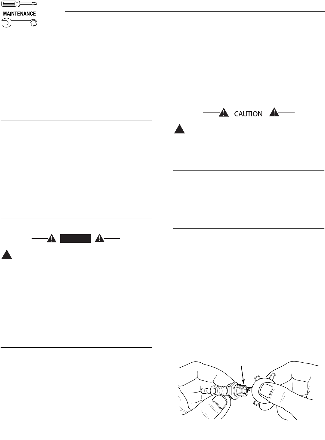
18 Bryant
4.8.5 CHECK ENGINE COOLANT LEVEL
See “Checking Fluid Levels”.
4.8.6 PERFORM VISUAL INSPECTION
Complete a thorough visual inspection of the entire
engine-generator monthly. Look for obvious damage,
loose, missing or corroded nuts, bolts and other fas-
teners. Look for fuel, oil or coolant leaks.
4.8.7 INSPECT EXHAUST SYSTEM
Inspect the exhaust system at least once every three
months. Check all exhaust system pipes, mufflers,
clamps, etc. for condition, tightness, leaks, security,
damage.
4.8.8 CHECK FAN BELT
• Inspect fan belts every three months. Replace any
damaged, deteriorated, worn or otherwise defec-
tive belt.
• Check fan belt tension. Thumb pressure, exerted
midway between pulleys, should deflect about 3/8
to 5/8 of an inch. Adjust belt tension as required.
4.8.9 INSPECT ENGINE GOVERNOR
Visually inspect electronic governor.
DANGER: Do not attempt to adjust the gover-
nor. Only qualified service facilities should
adjust the governor. Excessively high operating
speeds are dangerous and increase the risk of
personal injury. Low speeds impose a heavy
load on the engine when adequate engine
power is not available and may shorten engine
life. Correct rated frequency and voltage are
supplied only at the proper governed speed.
Some connected electrical load devices may be
damaged by incorrect frequency and/or volt-
age. Only qualified service technicians should
adjust the governed speed.
4.8.10 CHANGING ENGINE OIL
Refer to maintenance performed by authorized service
facilities for engine oil and filter change frequencies.
Drain the oil while the engine is still warm from run-
ning. This means warm up the engine, shut it down
and drain immediately as follows:
1. Remove OIL DRAIN HOSE from its retaining clip.
2. Loosen and remove OIL DRAIN HOSE CAP. Drain
oil completely into suitable container.
3. When all oil has drained, install and tighten OIL
DRAIN HOSE CAP, and re-install into its retaining
clip.
4. Turn OIL FILTER (Figure 4.1) counterclockwise
and remove. Properly dispose of old filter.
5. Apply light coating of new engine oil to seal of new
oil filter. Install FILTER and tighten by hand only.
DO NOT OVER TIGHTEN.
6. Remove OIL FILL CAP. Add recommended oil (see
SPECIFICATIONS). DO NOT FILL ABOVE THE
DIPSTICK “FULL” MARK. Crankcase oil capacity
is 4.0 U.S. quarts (3.8 liters).
After refilling the crankcase with oil, always
check oil level on dipstick. NEVER OPERATE
ENGINE WITH OIL BELOW THE DIPSTICK “ADD”
MARK.
7. Start engine and check for oil leaks.
4.8.11 CHANGING THE ENGINE AIR CLEANER
To replace the engine air cleaner, (part number
059402), simply remove the air cleaner cover and
replace the air filter making sure it is positioned
properly before reattaching the cover (Figure 4.1).
See the “Service Schedule,” for air cleaner mainte-
nance (Section 4.10).
4.8.12 SPARK PLUGS
Reset the spark plug gap or replace the spark plugs
as necessary (Figure 4.4).
1. Clean the area around the base of the spark plugs
to keep dirt and debris out of the engine. Clean by
scraping or washing using a wire brush and com-
mercial solvent. Do not blast the spark plugs to
clean.
2. Remove the spark plugs and check the condition.
Replace the spark plugs if worn or if reuse is
questionable. See the “Service Schedule,” Section
6, for recommended inspection.
3. Check the spark plug gap using a wire feeler
gauge. Adjust the gap to 1.07-1.17 mm (0.042-
0.046 inch) by carefully bending the ground elec-
trode (Figure 4.2).
Figure 4.4 – Setting the Spark Plug Gap
!
!
DANGER
Section 4 — Maintenance
Bryant Liquid-cooled 25 kW Generator
SET PLUG GAP AT 1.07 - 1.17 mm
(0.042 - 0.046 inch)
Bryant 19
4.8.13 COOLANT CHANGE
Every year, have a Bryant dealer drain, flush and
refill the cooling system. See “Specifications” for cool-
ing system recommendations.
4.9 MISCELLANEOUS MAINTENANCE
4.9.1 CLEANING THE GENERATOR
Keep the generator as clean and as dry as possible.
Dirt and moisture that accumulates on internal gen-
erator windings have an adverse effect on insulation
resistance.
Periodically clean generator exterior surfaces. A soft
brush may be used to loosen caked on dirt. Use a
vacuum system or dry, low pressure air to remove
any accumulations of dirt. The generator is housed
inside an all-weather enclosure, clean the enclosure
with a soft, damp cloth or sponge and water.
Once each year have the generator cleaned and
inspected by a dealer. That dealer will use dry, low
pressure air to clean internal windings. Parts inside
the control console should be cleaned and inspected
at this time as well.
Finally, have the insulation resistance of stator and
rotor windings checked. If insulation resistances are
excessively low, the generator may require drying.
4.9.2 BATTERY
All lead-acid storage batteries discharge when not in
use. Refer to specific instructions and warnings that
accompany the battery. If such information is not
available, observe the following precautions when
handling a battery:
• DO NOT use jumper cables and a booster battery
to crank or start the generator engine.
• DO NOT recharge a weak battery while it is
installed in the generator. Remove battery from
generator and recharge in a well-ventilated area,
away from fuel vapors, sparks, heat or flames.
• Battery electrolyte fluid is an extremely caustic
sulfuric solution that can cause severe burns. DO
NOT permit fluid to contact eyes, skin, clothing,
painted surfaces, wiring insulation, etc. If any bat-
tery fluid is spilled, flush the affected area with
clear water immediately.
• Always wear safety glasses, rubber apron and
gloves when handling a battery.
• Batteries give off explosive hydrogen gas while
charging. The gas can form an explosive mixture
around the battery for several hours after charging.
Any spark, heat or flames can ignite the gas and
cause an explosion which can shatter the battery,
causing blindness or other serious injury.
4.9.3 BATTERY MAINTENANCE
The battery should be inspected per Section 4.7,
Scheduled Maintenance. The following procedure
should be followed for inspection:
1. Inspect the battery posts and cables for tightness
and corrosion. Tighten and clean as necessary.
2. Check the battery fluid level of unsealed batteries
and, if necessary, fill with DISTILLED WATER
ONLY. DO NOT USE TAP WATER IN BATTERIES.
3. Have the state of charge and condition checked.
This should be done with an automotive-type bat-
tery hydrometer.
Storage batteries give off explosive hydrogen
gas. This gas can form an explosive mixture
around the battery for several hours after
charging. The slightest spark can ignite the gas
and cause an explosion. Such an explosion can
shatter the battery and cause blindness or
other injury. Any area that houses a storage
battery must be properly ventilated. Do not
allow smoking, open flame, sparks or any spark
producing tools or equipment near the battery.
Battery electrolyte fluid is an extremely corro-
sive sulfuric acid solution that can cause severe
burns. Do not permit fluid to contact eyes, skin,
clothing, painted surfaces, etc. Wear protective
goggles, protective clothing and gloves when
handling a battery. If fluid is spilled, flush the
affected area immediately with clear water.
Do not use any jumper cables or booster bat-
tery to crank and start the generator engine. If
the battery has completely discharged, remove
it from the generator for recharging.
Be sure the AUTO/OFF/MANUAL switch is set to
the OFF position, before connecting the battery
cables. If the switch is set to AUTO or MANUAL,
the generator can crank and start as soon as
the battery cables are connected.
Be sure the utility power supply is turned off,
or sparking may occur at the battery posts as
the cables are attached and cause an explosion.
!
!
!
DANGER
Section 4 — Maintenance
Bryant Liquid-cooled 25 kW Generator

20 Bryant
4.9.4 BATTERY REPLACEMENT
When replacing batteries, use the same number and
the type of battery that follows:
NOTE:
The BCI number should be located directly
on the battery.
Section 4 — Maintenance
Bryant Liquid-cooled 25 kW Generator
BCI Group No. CCA
26 525 @ 0 deg. F
PERIODIC REPLACEMENT PARTS
Part Name Part Number
Oil Filter # 0F4604A
Radiator Cap # 046627
Air Cleaner # 059402
Spark Plug # 0E96180241

Bryant 21
Section 4 — Maintenance
Bryant Liquid-cooled 25 kW Generator
4.10 SCHEDULED MAINTENANCE
Following is a recommended maintenance schedule for small standby and residential generator sets. The estab-
lished intervals in the schedule are the maximum recommended when the unit is used in an average service appli-
cation. They will need to be decreased (performed more frequently) if the unit is used in a severe application. Use
the unit hour meter or calendar time, whichever occurs first, from the previous maintenance interval to determine
the next required maintenance interval.
Service Maintenance Interval Information:
The various service maintenance intervals are designated by interval numbers as follows:
1An early inspection of the generator set to insure it is ready to operate when required and to identify any poten-
tial problem areas.
Performed monthly this requires approximately .5 man-hours per unit to complete.
This inspection may be performed by the end user providing the following safety steps are taken to prevent
the engine from starting automatically without warning:
To prevent injury, perform the following steps in the order indicated before starting any maintenance:
• Disable the generator set from starting and/or connecting to the load by setting the control panel
AUTO/OFF/MANUAL switch to the OFF position.
• Remove the 5 amp and 15 amp control panel fuses.
• Turn off the battery charger (turn OFF utility supply to ATS).
• Remove the negative battery cable.
The battery charger must be turned off BEFORE removing the battery cable to prevent an over current condi-
tion from burning out sensitive control panel components and circuits.
Following all maintenance, reverse these steps to insure the unit is returned to standby setup for normal
operation when required.
2A break-in service inspection of the generator set to insure it is ready to operate and carry the load when
required, and to identify any potential problem areas.
Performed ONLY ONCE following the first three months of operation after purchase of the unit and requires
approximately 2.5 man-hours per unit to complete.
This inspection contains some maintenance tasks which require special tools, equipment, and/or knowledge
to accomplish and should be performed only by a dealer.
3An operational inspection of the generator set to insure it is ready to operate and carry the load when required,
and to identify any potential problem areas.
Performed semi-annually this requires approximately 1.5 man-hours per unit to complete.
This inspection contains some maintenance tasks which require special tools, equipment, and/or knowledge
to accomplish and should be performed only by a dealer.
4A mid-level inspection of the generator set to insure it is ready to operate and carry the load when required, and
to identify any potential problem areas.
Performed annually this requires approximately 4.0 man-hours per unit to complete.
This inspection contains some maintenance tasks which require special tools, equipment, and/or knowledge
to accomplish and should be performed only by a dealer.
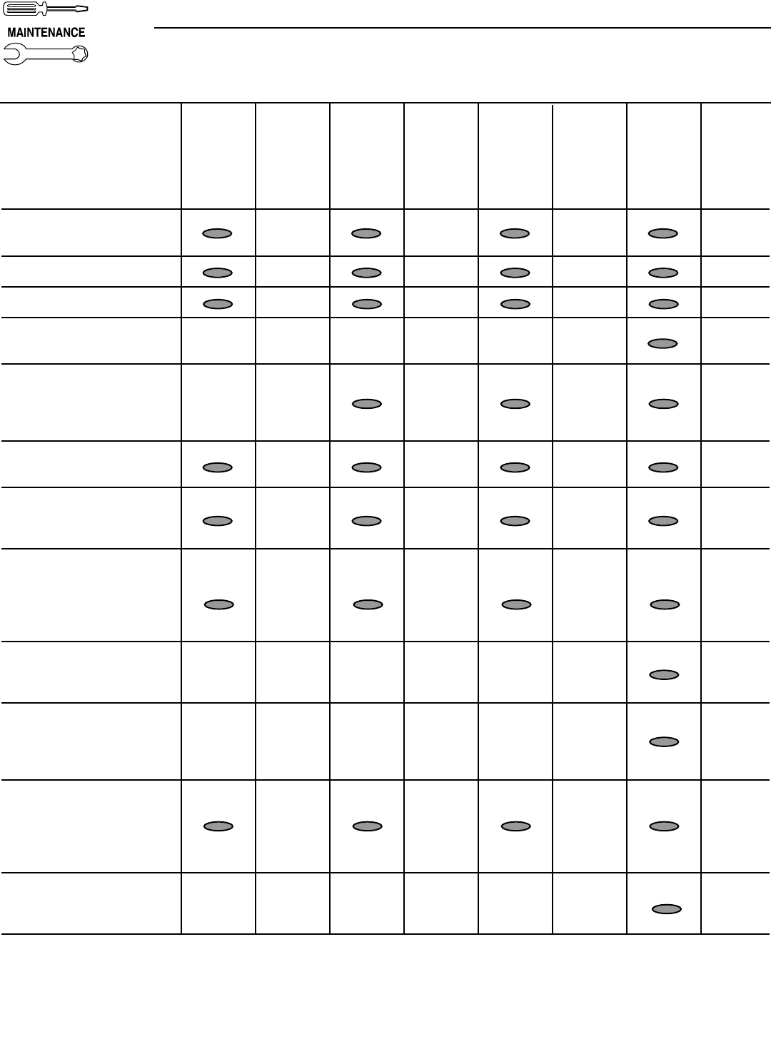
22 Bryant
Section 4 — Maintenance
Bryant Liquid-cooled 25 kW Generator
Maintenance Level 1 Level 2 Level 3 Level 4
Tasks Recom- Task Required Task Required Task Task
mended Comp. to be done Comp. to be done Comp. Required Comp.
to be done (Date- 3 months/ (Date- Semi- (Date- to be done (Date-
monthly Initials) Break-in Initials) annually Initials) Annually Initials)
1. Disable the unit from
operating per the first page
warning.
2. Check the engine oil level.
Adjust as necessary.
3. Check the engine coolant
level. Adjust as necessary.
4. Check the engine coolant
thermal protection level.
Correct as necessary.
5. Check the natural gas
delivery system on gas
engine driven units.
Tighten connections as
necessary.
6. Check the air inlets and
outlets for debris. Clean as
necessary.
7. Check the battery
electrolyte level if
accessible. Adjust as
necessary.
8. Check the battery posts,
cables, and charger for
loose connections,
corrosion, and proper
operation. Correct as
necessary.
9. Check the unit wiring for
loose connections,
corrosion, and damage.
Correct as necessary.
10. Check the engine
accessory drive belts for
wear, weather cracking,
and damage. Replace as
necessary.
11. Visually inspect the unit
looking for leaks, wear or
damage, loose connections
or components, and
corrosion. Correct as
necessary.
12. Test the engine and
transfer switch safety
devices. Correct and/or
adjust as necessary.
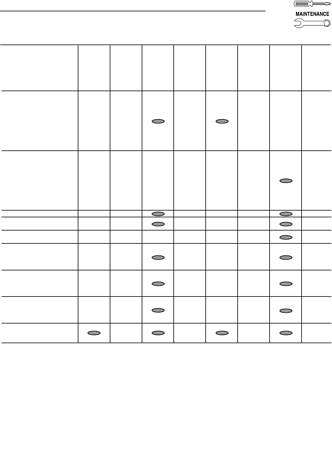
Bryant 23
Section 4 — Maintenance
Bryant Liquid-cooled 25 kW Generator
Maintenance Level 1 Level 2 Level 3 Level 4
Tasks Recom- Task Required Task Required Task Task
mended Comp. to be done Comp. to be done Comp. Required Comp.
to be done (Date- 3 months/ (Date- Semi- (Date- to be done (Date-
monthly Initials) Break-in Initials) annually Initials) Annually Initials)
13. Initiate an automatic start
and transfer of the unit to
site load and exercise it for
at least 1 hour looking for
leaks, loose connections
or components, and
abnormal operating
conditions. Correct as
necessary.
14. Start and exercise the unit
at full rated load (use a
load bank if the site load is
not enough) for at least 2
hours looking for leaks,
loose connections or
components, and abnormal
operating conditions.
Correct as necessary.
15. Change the engine oil.
16. Replace the engine oil
filter(s).
17. Replace the engine air
filter(s).
18. Replace the engine fuel
filter(s) on diesel engine
driven units and re-prime
the fuel system.
19. Check the engine spark
plugs on gas engine driven
units. Clean and re-gap or
replace as necessary.
20. Perform a 5 minute no-load
operational run of the unit
looking for any post service
problems.
21. Return the unit to standby
setup for operation when
required.

24 Bryant
Section 5 — Troubleshooting
Bryant Liquid-cooled 25 kW Generator
TROUBLESHOOTING POINTS
PROBLEM CAUSE CORRECTION
Engine won’t crank. 1. 15 amp fuse blown. 1. Replace fuse.
2. Loose or corroded or defective 2. Tighten, clean or replace
battery cables. battery cables as necessary.
3. Defective starter contactor. 3. Replace contactor.
4. Defective starter motor. 4. Replace starter motor.
5. Dead or Defective Battery. 5. Remove, change or replace battery.
6. 5 amp fuse blown. 6. Replace fuse.
Engine cranks but won't start 1. Out of fuel. 1. Replenish fuel.
2. Fuel solenoid (FS) is defective 2. Replace solenoid.
3. Open Wire #14A from Engine Control 3. Reconnect wire.
circuit board.
4. Spark plugs defective. 4. Clean, regap or replace plugs.
Engine starts hard, runs rough. 1. Flame arrestor (air cleaner) plugged or 1. Clean or replace as needed.
damaged.
2. Plugged fuel line. 2. Unclog fuel line.
3. Defective spark plugs. 3. Clean, regap or replace plugs.
Engine starts then shuts down. 1. Engine oil level is low. 1. Check oil and add oil as needed.
2. Engine is overheated. 2. Check cooling system for leaks.
3. Defective Low Oil Pressure Switch 3. Replace switch.
4. Defective Coolant Temperature Switch 4. Replace switch.
5. Defective Control Module circuit board. 5. Replace board.
6. Coolant Level is Low. 6. Repair leak - Add coolant.
7. Defective Low Coolant Level Switch 7. Replace Switch.
AUTO/OFF/MANUAL Switch at OFF, 1. Defective AUTO/OFF/MANUAL switch 1. Replace switch.
engine continues to run 2. Open/disconnected wire #15A between 2. Reconnect/close wire.
AUTO/OFF/MANUAL switch and Control
Module circuit board.
3. Defective Control Module circuit board 3. Replace board.
No AC output from generator. 1. Check main line circuit breaker. 1. Reset to ON or CLOSED.
2. Check circuit breaker & fuses. 2. Reset and replace, if necessary.
3. Transfer switch set to NORMAL position 3. Set to GENERATOR position.
4. Generator internal failure. 4. Contact a dealer.
5. Thermal circuit breaker open. 5. Auto-reset - Wait 5 min. and
attempt restart.
NOTE:
Under normal operating conditions, if repair of generator set or replacement of any parts is necessary dur-
ing the warranty period, you must contact a dealer. Failure to have the repair or replacement performed by
a Bryant dealer will result in non-coverage of warranty repair cost.

Bryant 25
Section 6 — Notes
Bryant Liquid-cooled 25 kW Generator

26 Bryant
Section 6 — Notes
Bryant Liquid-cooled 25 kW Generator

Bryant 27
Section 6 — Notes
Bryant Liquid-cooled 25 kW Generator
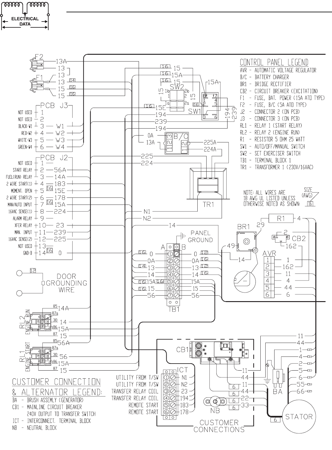
28 Bryant
Section 7 - Electrical Data
Bryant Liquid-cooled 25 kW Generator
Wiring Diagram — 2.5L Engine — Drawing No. 0F1411-A
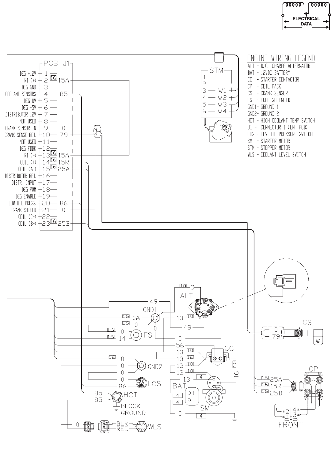
Bryant 29
Section 7 - Electrical Data
Bryant Liquid-cooled 25 kW Generator
Wiring Diagram — 2.5L Engine — Drawing No. 0F1411-A
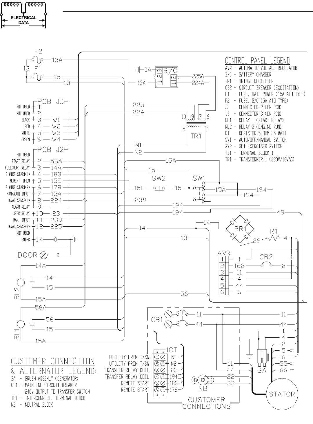
30 Bryant
Section 7 - Electrical Data
Bryant Liquid-cooled 25 kW Generator
Electrical Schematic — 2.5L Engine — Drawing No. 0F1413-A
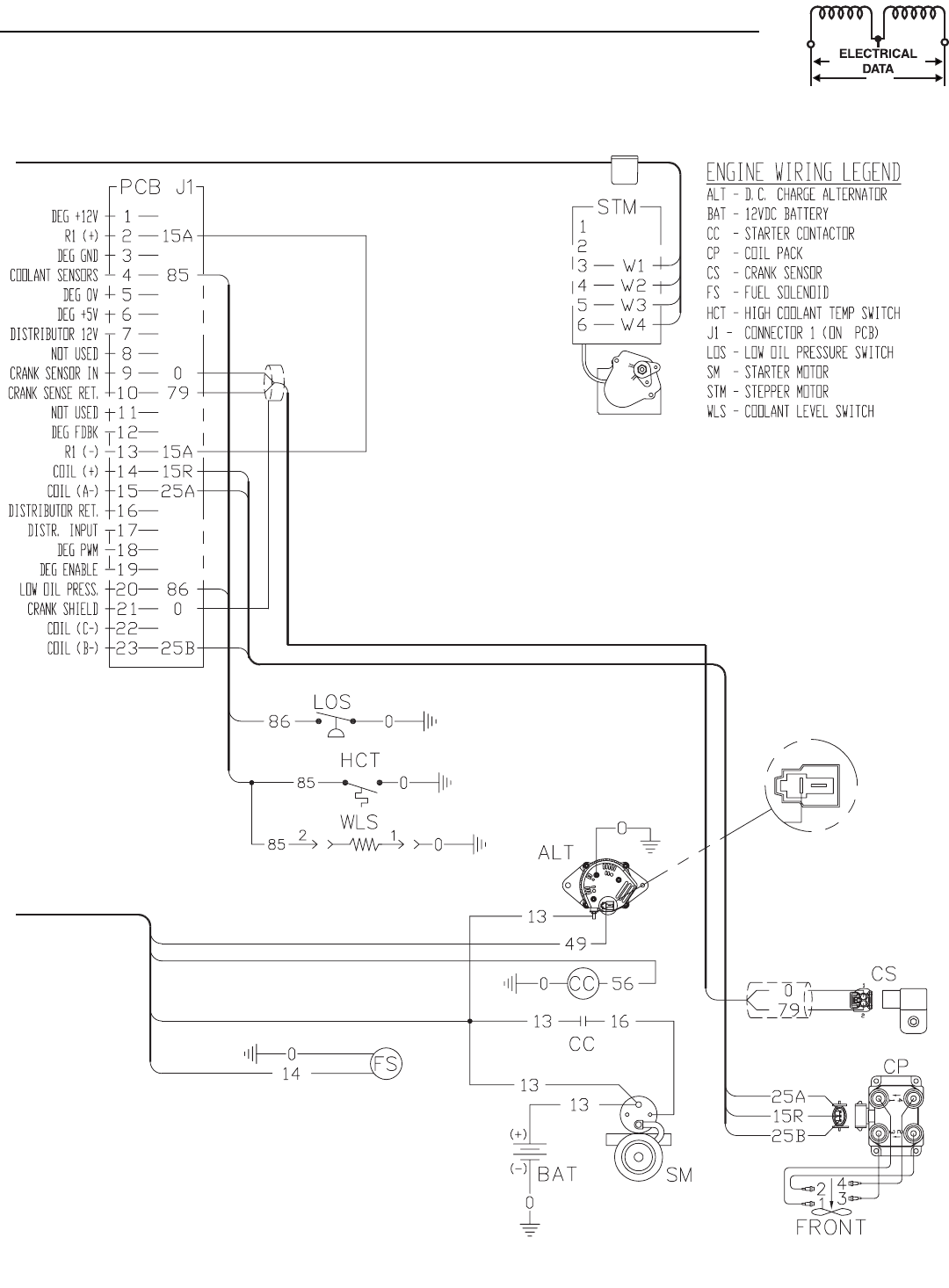
Bryant 31
Section 7 - Electrical Data
Bryant Liquid-cooled 25 kW Generator
Electrical Schematic — 2.5L Engine — Drawing No. 0F1413-A
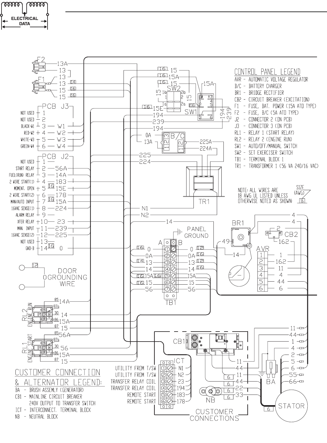
32 Bryant
Section 7 - Electrical Data
Bryant Liquid-cooled 25 kW Generator
Wiring Diagram — 2.5L Engine (25kW unit) —Drawing No. 0E9982-C
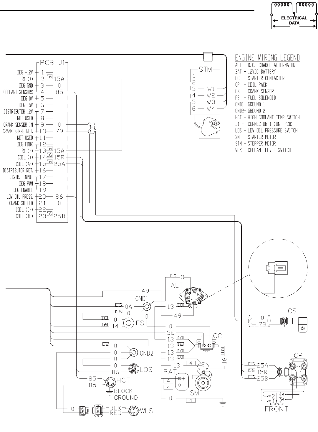
Bryant 33
Section 7 - Electrical Data
Bryant Liquid-cooled 25 kW Generator
Wiring Diagram — 2.5L Engine (25kW unit) —Drawing No. 0E9982-C
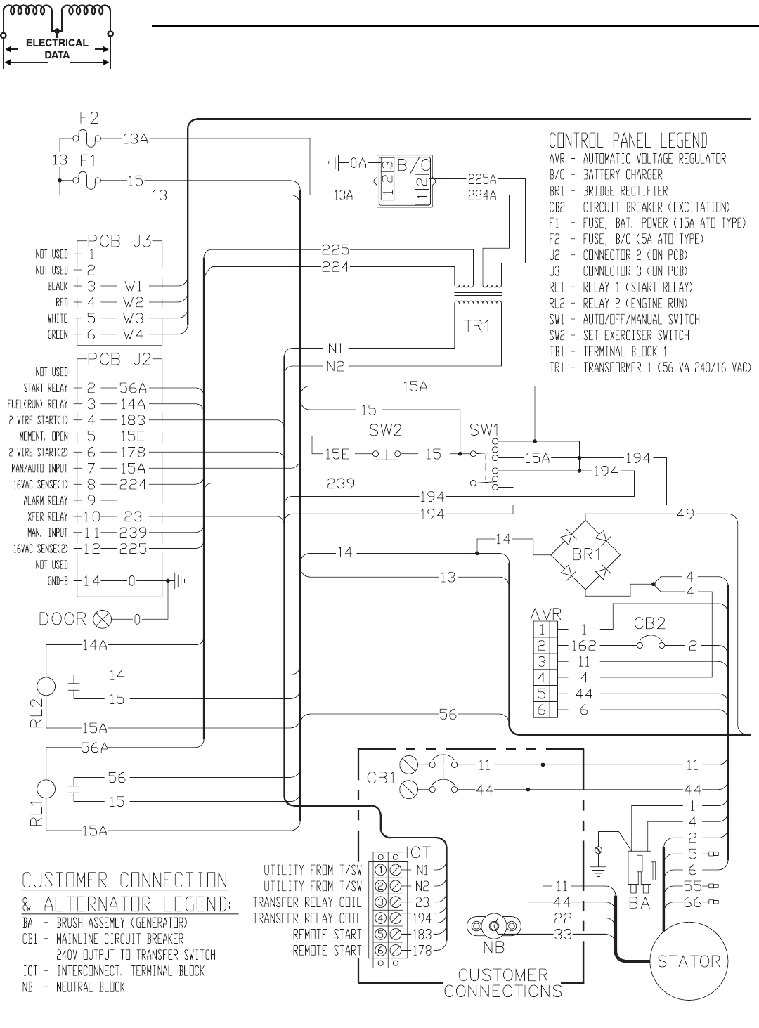
34 Bryant
Section 7 - Electrical Data
Bryant Liquid-cooled 25 kW Generator
Electrical Schematic — 2.5L (25kW unit) — Drawing No. 0E9983-C
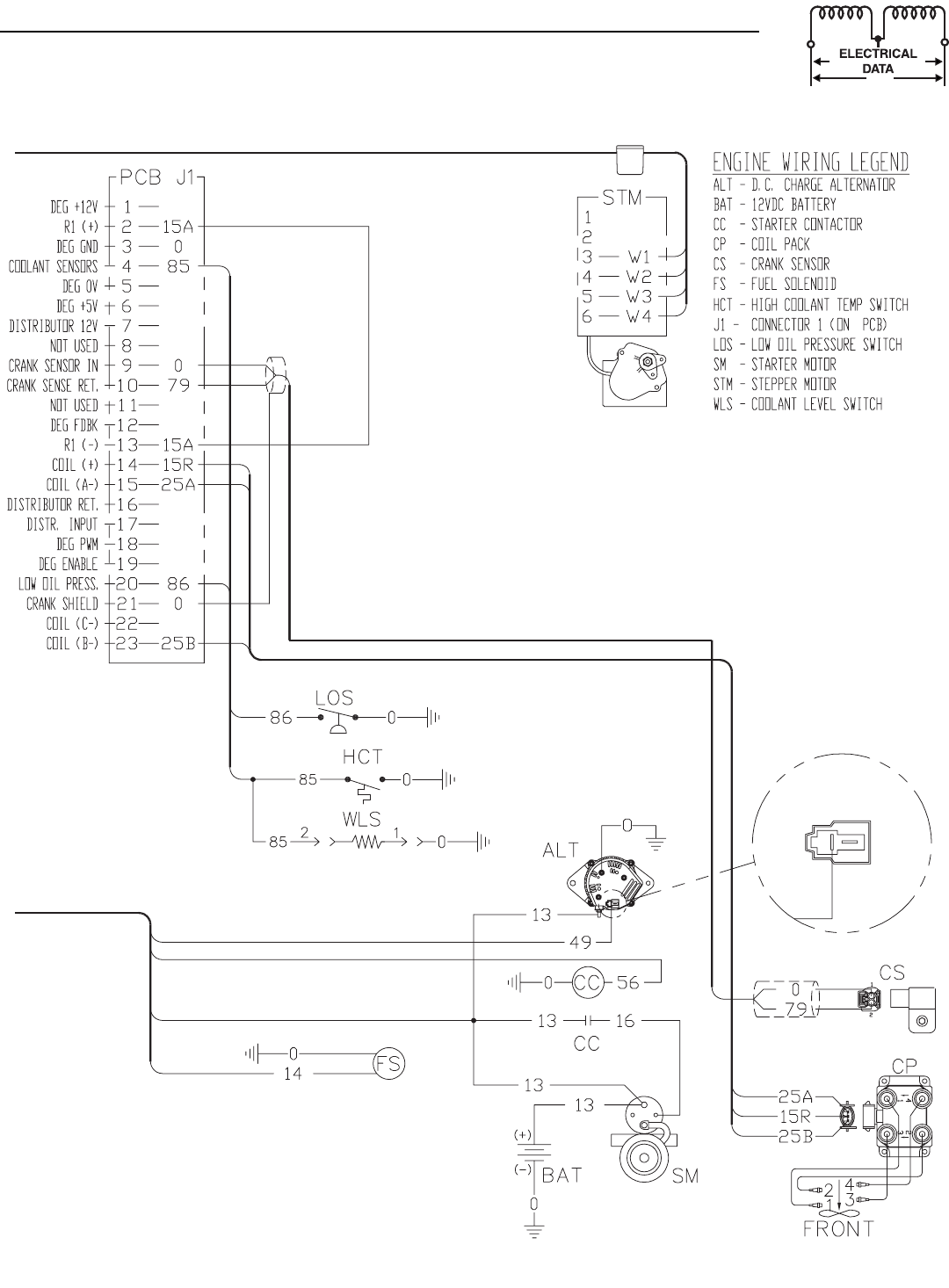
Bryant 35
Section 7 - Electrical Data
Bryant Liquid-cooled 25 kW Generator
Electrical Schematic — 2.5L (25kW unit) — Drawing No. 0E9983-C
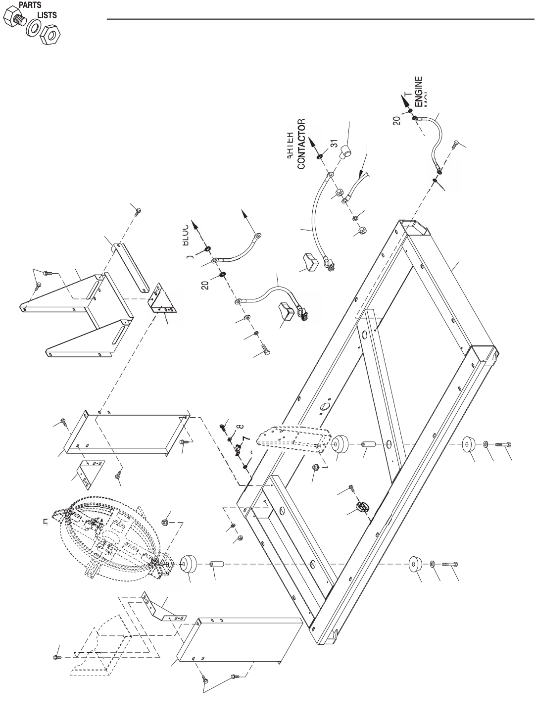
36 Bryant
Section 8 - Exploded Views and Parts
Bryant Liquid-cooled 25 kW Generator
Mounting Base — Drawing No. 0E9964-E
28
E
N
G
INE
BLOCK
5
CARRIER
R
EAR BEARIN
G
1
4
15
13
3
BO
TT
O
M
P
ANEL
3
2
12
4
1
11
15
14
13
33
2
3
12
11
36
35
10
10
3
1
6
8
9
3
22
21
27
23
1
25
26
29
3
4
20
24
TO
19
3
3
3
30
H
ARNE
SS
6
1
7
16
MOUNT
2
WIRE
O
STARTER
TO
S
TARTER
29
BO
LT
TO
3
3
2

Bryant 37
Section 8 - Exploded Views and Parts
Bryant Liquid-cooled 25 kW Generator
Mounting Base — Drawing No. 0E9964-E
ITEM PART NO. QTY. DESCRIPTION
1 0D9336 3 PANEL BRACKET
2 0E9939 2 CTRL PNL SUPPORT 2.5L FORD
3 0C2454 24 SCREW TH-FRM M6-1 X 16 N WA Z/JS
4 049813 1 NUT HEX M6 X 1.0 G8 YEL CHR
5 022097 1 WASHER LOCK M6-1/4
6 026850 2 WASHER SHAKEPROOF EXT 1/4 STL
7 055414 1 LUG SLDLSS #2-#8 X 17/64 CU
8 022473 1 WASHER FLAT 1/4-M6 ZINC
9 047411 1 SCREW HHC M6-1.0 X 16 G8.8
10 052860 4 NUT FLANGED HEX M12-1.75
11 052251 4 DAMPENER VIBRATION 40 BLUE
12 052257 4 SPACER .49 X .62 X 1.87 PWDR/ZNC
13 052252 4 DAMPENER VIBRATION
14 052259 4 WASHER FLAT M12
15 052891 4 SCREW HHC M12-1.75 X 80 G8.8
16 0536210261 1 ASSY WIRE #0 12.00"
17 074906 1 SCREW HHTT M6-1.0 X 20 BP
18 077483 REF BATT 12VDC 75-AH 26 (NOT SHOWN)
19 0E9941 1 HOLD DOWN BATTERY 2.5L FORD
20 025507 3 WASHER SHAKEPROOF EXT 7/16 STL
21 059980 1 SCREW HHC M10-1.5 X 25 G10.9
22 046526 1 WASHER LOCK M10
23 022131 1 WASHER FLAT 3/8-M10 ZINC
24 021991 1 EARTH STRAP
25 038805J 1 CABLE BATT BLK #1 X 30.00
26 050331 REF BATTERY POST COVER (BLACK)
27 050331A REF BATTERY POST COVER (RED)
28 038804J 1 CABLE BATT RED #1 X 40.50
29 045771 REF NUT HEX M8-1.25 G8 YEL CHR
30 022129 REF WASHER LOCK M8-5/16
31 027482 1 WASHER SHAKEPROOF EXT 5/16 STL
32 075763 1 BOOT BATTERY CABLE
33 0E9748 1 ASSY MTG BASE 2.5L FORD
34 0E9940 1 TRAY BATTERY 2.5L FORD
35 065852 1 SPRING CLIP HOLDER .37-.62
36 024469 1 SCREW HHTT #10-32 X 3/8 CZ
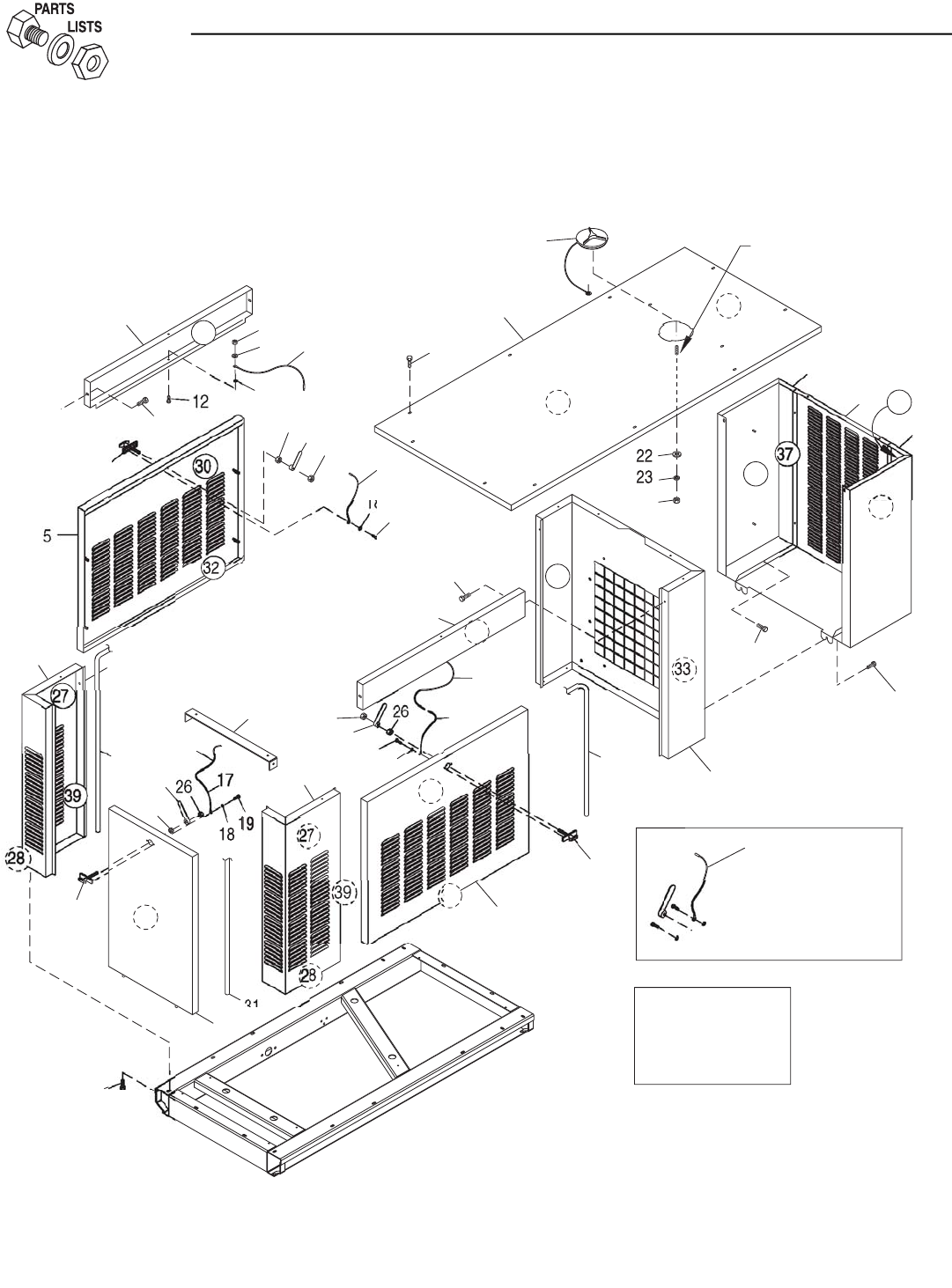
38 Bryant
Section 8 - Exploded Views and Parts
Bryant Liquid-cooled 25 kW Generator
Enclosure — Drawing No. 0F4568-B
35
N
U
T
S
ITEM #2
6.
US
E L
OC
TITE
ON
PANEL F
O
R A
CC
E
SS
CO
VER
C
ABL
E
WELD
S
T
U
D
U
NDER R
OOF
17
G
R
OU
ND WIRE
.
FA
S
TENER T
O
S
E
CU
R
E
US
E D
OO
R LAT
CH
N
O
TE
:
2
6
38
11
2
5
31
7
9
24
1
0
4
2
6
2
5
1
5
8
29
11
1
6
14
1
3
1
0
5
32
N
O
TE
:
30
11
4
1
9
2
6
6
1
0
1
8
1
0
2
6
"Y"
1
5
"
Y"
17
1
9
18
33
3
11
17
29
2
1
5
1
34
21
36
24
3
2
0
11
35
3
41
2
11
4
0
37
3

Bryant 39
ITEM PART NO. QTY. DESCRIPTION
1 0E9768 1 ROOF ACO & STD ENCL 2.5L
2 0E9862 1 DUCT DISCHARGE MID 2.5L
3 0E9769 1 SUPPORT RADIATOR 2.5L FORD
4 0D8660 2 BRACE SIDE 1.5L MITSU
5 0A7568 2 DOORWELDMENT 1.5EPS
6 0E9771 1 CORNER POST REAR RH SIDE 2.5L
7 0E9773 1 DOOR REAR ENCL 2.5L FD
8 0E9772 1 BRACE, REAR 2.5L FORD
9 0E9770 1 CORNER POST REAR LH SIDE 2.5L
10 067042 2 LATCH & CAM
11 0C2454 34 SCREW TH-FRM M6-1 X 16 N WA Z/JS
12 033530 3 SCREW PHM #10-32 X 5/8 ZINC
13 051716 3 NUT HEX M5-0.8 G8 YEL CHR
14 022152 3 WASHER LOCK #10
15 0912970064 3 ASSEMBLY BASE-DOOR GROUND WIRE
16 023762 3 WASHER SHAKEPROOF EXT #10 STL
17 0912970063 3 GRD WIRE ASS'Y 99HSB
18 022264 6 WASHER LOCK #8-M4
19 067035 6 SCREW PPHM #8-32 X 5/16
20 022127 1 NUT HEX 1/4-20 STEEL
21 0F4487A 1 ASSEMBLY COVER ACCESS
22 022473 1 WASHER FLAT 1/4 ZINC
23 022097 1 WASHER LOCK M6-1/4
24 0D2023 2 GASKET CLIP-ON SELF GRIPPING (89" LG)
25 0F3390 1 LATCH AND CAM
26 037337 6 NUT HEX JAM 3/8-24 SS
27 0E0072G 2 ACSTC INSLTN 1.5L RR CRNR TOP
28 0E0072J 2 ACSTC INSLTN 1.5L RR CRNR BOTT
29 0E0072L 2 ACSTC INSLTN 1.5L SIDE BRC PNL
30 0E0072M 2 ACSTC INSLTN 1.5L SIDE DR PNL
31 0D2023 1 TRIM VINYL SELF GRIPPING (80" LG)
32 0E0072P 2 ACSTC INSLTN 1.5L SIDE DR PNL
33 0E0072Q 2 ACSTC INSLTN 1.5L RAD SUPPORT
34 0E0072S 1 ACSTC INSLTN 2.5L ROOF
35 0E0072T 2 ACSTC INSLTN 2.5L DUCT L & RH SD
36 0E0072U 1 INSUL ACO 2.5L EXH ROOF PANEL
37 0E0072V 2 ACSTC INSLTN 2.5L DUCT FRNT SD
38 0E0072W 1 ACSTC INSLTN 2.5L REAR DOOR
39 0E0072X 2 ACSTC INSLTN 2.5 RR CRNR PNL S
40 0E9861 1 DUCT DISCHARGE RH SIDE 2.5L
41 0E9860 1 DUCT DISCHARGE LH SIDE 2.5L
Section 8 - Exploded Views and Parts
Bryant Liquid-cooled 25 kW Generator
Enclosure — Drawing No. 0F4568-B
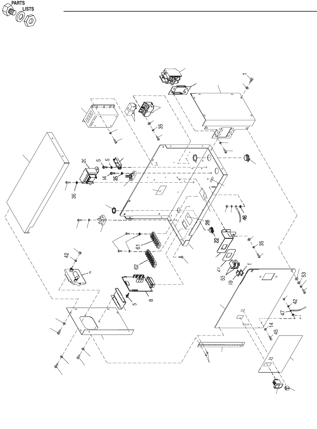
40 Bryant
6
TO
"A"
15
4
19
5
3
2
44
40
14
1
14
26
10
14
1
24
2
9
33
3
1
50
5
2
41
33
4
48
13
27
36
5
4
"A"
23
65
3
7
35
2
7
3
35
9
3
4
43
3
4
21
35
17
30
3
4
22
3
35
16
36
3
4
0
56
5
12
14
11
6
4
5
4
38
18
39
Section 8 - Exploded Views and Parts
Bryant Liquid-cooled 25 kW Generator
Control Panel — Drawing No. 0E9719-E

Bryant 41
ITEM PART NO. QTY. DESCRIPTION
1 0C2267 16 SCREW HHTT M5-0.8 X 12 BP
3 0D5070A 1 ASSY 2A 12V UL BATTERY
CHARGER
4 0D8671 1 HINGE CONTINUOUS 1.5L CTRL PNL
5 0E4494 1 SWITCH ROC DPDT ON-OFF-ON
6 0E6875A 2 RELAY, 12VDC C FORM W/DIODE
7 0E7358 4 SCREW PPPH HI-LO #4-24 X 3/8
8 0E9704 1 ASSY PCB HSB CONTROLLER 2.5L
9 0E9934 1 CTRL PNL BACK & BOTTOM 2.5L
10 0E9935 1 CTRL PNL LH SIDE 2.5L FORD
11 0E9936 1 CTRL PNL RH SIDE 2.5L FORD
12 0E9937 1 CTRL PNL TOP 2.5L FORD
13 0E9938 1 CTRL PNL FRONT 2.5L FORD
14 023897 19 WASHER FLAT #10 ZINC
15 036261 4 RIVET POP .125 X .275 AL
16 054450 1 CIRCT BRK 5.5 X 1 ETA 46-500-P
17 057073 1 JUNCTION BLOCK 3/8-16
18 067680 1 ASSY VOLTAGE REGULATOR 60HZ
19 082573 1 SWITCH ROC DPST 125V SPD
20 0C3910 1 TRANSFORMER 240/16V 1VA & 56VA
21 029673 1 DIO BRIDGE 25A 600V
22 034616 1 FITTING STRAIGHT 3/4
23 0E2514 1 FITTING CONDUIT STR 1-1/2"
24 0F0581 1 BRACKET FUSE HOLDER 2.5L FORD
25 040213 2 PCB SUPPORT SNAP-IN 1/4"
26 0F0558 1 BRACKET PCB SUPPORT 2.5L FORD
27 0F0598 1 DECAL FUSES 2.5L CNTRL PANEL
28 0F0599 1 DECAL TB1 2.5L CONTROL PANEL
29 0F0600 1 DECAL ICT 2.5L CONTROL PANEL
30 054199 1 DECAL DANGER HIGH VOLTAGE
31 049813 1 NUT HEX M6 X 1.0 G8 YEL CHR
32 0F0653 1 DECAL CONTROL HSB 2.5L FORD
33 022097 3 WASHER LOCK M6-1/4
34 0C2212 13 SCREW PHTT M4-0.7 X 16 ZYC
35 022264 20 WASHER LOCK #8-M4
36 0C2265 5 SCREW PHTT M4-0.7 X 12 ZYC
ITEM PART NO. QTY. DESCRIPTION
37 023965 2 SCREW RHM #8-32 X 3/8
38 039782 1 BRKT MTG CB BQ
39 0A2077 1 CB 0125A 2P 240V S BQ2 LL
40 020911 2 SCREW PPHM M5-0.8 X 30 ZINC
41 0A8955 2 SCREW PHM M6-1.0 X 20MM
42 022152 3 WASHER LOCK #10
43 051716 2 NUT HEX M5-0.8 G8 YEL CHR
44 023762 1 WASHER SHAKEPROOF EXT #10
STL
45 033121 1 SCREW HHC #10-32 X 1/2
46 026850 1 WASHER SHAKEPROOF EXT 1/4
STL
47 0912970087 1 ASSY WIRE 14AWG 16" #0 GRN/YEL
48 022158 1 NUT HEX #10-32 STEEL
49 0E7403C 1 FUSE ATO TYPE 15 AMP (BLUE)
50 0E7403A 1 FUSE ATO TYPE 5 AMP (TAN)
51 0F0526 1 HARN CTRL PNL 2.5L FD (NOT
SHOWN)
52 0A2115 2 WASHER NYLON .257
53 022473 2 WASHER FLAT 1/4-M6 ZINC
54 038150 5 WASHER FLAT #8 ZINC
55 0C2428 2 SCREW PHTT #6-32 X 1/2 ZYC
56 022155 2 WASHER LOCK #6
57 * 052619 2 SCREW HHC M5-0.8 X 20 G8.8
58 * 023897 4 WASHER FLAT #10 ZINC
59 * 049226 2 WASHER LOCK M5
60 * 051716 2 NUT HEX M5-0.8 G8 YEL CHR
61 ** 046357 REF BLOCK TERM 20A 6 X 6 X 1100V
62 ** 047822 REF BLOCK TERM 20A 7 X 6 X 1100V
63 ** 0F1467 REF ASSY WIRE FUSE HOLDER
64 ** 0E6881 REF SOCKET RELAY
65 0A9457 1 DECAL NEUTRAL
* NOT SHOWN. HARDWARE FOR ATTACHING WIRES TO I/N 39.
** PART OF I/N 51, P/N 0F0526 CONTROL PANEL HARNESS.
Section 8 - Exploded Views and Parts
Bryant Liquid-cooled 25 kW Generator
Control Panel — Drawing No. 0E9719-E
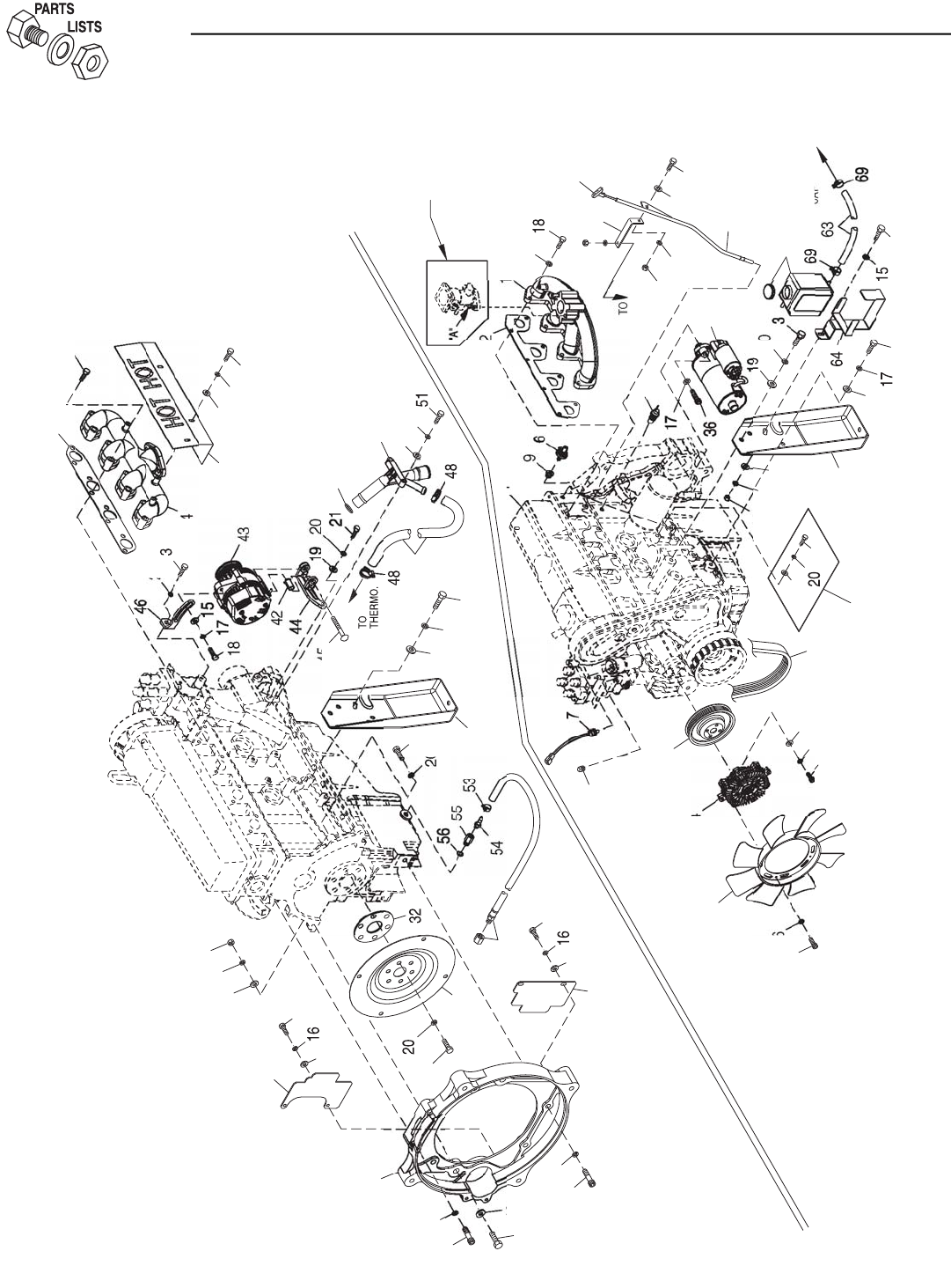
42 Bryant
8
15
66
16
14
19
41
30
20
27
60
20
30
29
28
59
39
5
2
19
38
39
20
40
2
25
4
17
13
15
19
FO
R HARNE
SS
G
R
OU
ND
5
3
22
17
68
15
19
10
38
22
3
1
0
HSG
.
20
3
4
7
45
20
49
1
16
39
50
34
35
65
33
5
7
18
3
7
18
20
16
38
R
ADIAT
O
R
CAP
6
2
TO
58
39
S
TEPPER
MO
T
O
R
U
NIT
S
O
NLY
17
12
"A
"
11
6
7
24
23
6
1
Section 8 - Exploded Views and Parts
Bryant Liquid-cooled 25 kW Generator
Engine — Drawing No. 0E9918-F

Bryant 43
ITEM PART NO. QTY. DESCRIPTION
1 0E9909 REF ENGINE 2.5L FORD
2 0E9739 1 PULLEY, 2.5L FORD WATER PUMP
3 049814 8 SCREW HHC M10-1.5 X 25 G8.8
4 0F0001 1 CLUTCH, COOLING FAN 2.5L FORD
5 0D3488B 1 SERPENTINE BELT - 40.85" LENGTH
6 0A8584 1 SWITCH,OIL PRESSURE,10PSI,2POL
7 0E0561 1 ASSY WATER LEVEL SENSOR C/E
PL
8 0A6751 1 SW-TMP 245DEG 3/8NPT
9 035579 1 BUSHING REDUCER 1/4 TO 1/8
10 026925 1 PLUG STD PIPE 3/8 STEEL SQ HD
11 0E9611 1 MANIFOLD, INTAKE (MACHINED)
(STEPPER MOTOR)
0E9611A 1 MANIFOLD INTAKE MACH BOSCH32
(BOSCH GOV.) (NOT SHOWN)
12 0E9681 1 GASKET, 2.5L FORD INTAKE MAN.
13 039253 4 SCREW HHC M8-1.25 X 20 G8.8
14 097962 4 SCREW SHC M6-1.0 X 25 G12.9 ZP
15 022145 8 WASHER FLAT 5/16-M8 ZINC
16 022097 11 WASHER LOCK M6-1/4
17 022129 16 WASHER LOCK M8-5/16
18 043107 11 SCREW HHC M8-1.25 X 25 G8.8
19 022131 19 WASHER FLAT 3/8-M10 ZINC
20 046526 22 WASHER LOCK M10
21 052625 2 SCREW SHC M10-1.5 X 35 G12.9
22 0E9708 2 ENGINE FOOT, 2.5L FORD
23 0E9738 1 DIPSTICK, 2.5L FORD
24 0E9929 1 BRACKET, DIPSTICK TUBE
25 0F0230 1 FAN 16" COOLING
26 0E9834 1 HARNESS, 2.5L FORD ENGINE (NOT
SHOWN)
0E9834A 1 HARNESS,2.5L FORD (BOSCH GOV.)
(NOT SHOWN)
27 0D5417 6 SCREW HHC M10-1.0 X 25 G10.9
28 0E5048B 1 FLEXPLATE 2.5L FORD
29 0E9655 1 ADAPT CASTING MACH 2.5L FORD
30 057192 4 SCREW SHC M10-1.5 X 30 G12.9
31 060619 2 SCREW SHC M10-1.50 X 40 G12.9
32 0E8940 1 SPACER FLEXPLATE HSB
33 0E9680 1 GASKET, 2.5L FORD EXHAUST MAN.
34 0E9609 1 MANIFOLD, EXHAUST ( MACHINED)
ITEM PART NO. QTY. DESCRIPTION
35 0E9930 1 HEAT SHIELD, EXHAUST MANIFOLD
36 049821 3 SCREW SHC M8-1.25 X 30 G12.9
37 0E9747 1 STARTER, 12 VOLT
38 043116 5 SCREW HHC M6-1.0 X 12 G8.8
39 022473 6 WASHER FLAT 1/4-M6 ZINC
40 045772 2 NUT HEX M10-1.5 G8 YEL CHR
41 064416 2 SCREW HHC M10-1.5 X 45 G8.8
42 0F0252 1 SPRING BUSHING
43 0E9868 1 ALTERNATOR, D.C
44 0F0035 1 BRKT,D.C. ALTERNATOR(MACHINED)
45 026082 1 SCREW HHC 3/8-16 X 2-1/4 G5
46 0E9928 1 TENSIONER, D.C. ALTERNATOR
47 0F0383 1 HOSE,2.5L FORD COOLANT BY-
PASS
48 057823 2 CLAMP HOSE #10 .56-1.06
49 0E9737 1 LOWER HOSE ADAPTER,2.5L FORD
50 0F0393 1 O-RING 1-3/16 X 1-7/16 X 1/8
51 045757 2 SCREW HHC M6-1.0 X 25 G8.8
52 069860C 1 HOSE OIL DRAIN ASSY 21"
53 048031J REF HOSE CLAMP BAND 5/8"
54 055596 1 BARBED STR 3/8NPT X 3/8
55 077456 1 ADAPTER M12-1.75 3/8NPT
56 052677 1 WASHER NYLON .50 X .87 X .06
57 049813 1 NUT HEX M6 X 1.0 G8 YEL CHR
58 0E9738A 1 DIPSTICK TUBE, 2.5L FORD
59 0F1132 1 COVER, R/H SIDE ENGINE
ADAPTOR
60 0F1133 1 COVER, L/H SIDE ENGINE ADAPTOR
61* 059355 8 SCREW SHC M10-1.50 X 50 G12.9
62 076749 1 TANK COOLANT RECOVERY
63 029032 1 HOSE 9/32 ID (39"LG)
64 0F1433 1 BRACKET,2.5L FORD WATER
BOTTLE
65 070007 3 WASHER FLAT M6 SS
66 070005 3 WASHER LOCK M6 SS
67 080826 3 SCREW HHC M6-1.0 X 12 SS
68 045771 1 NUT HEX M8-1.25 G8 YEL CHR
69 048031C 2 CLAMP HOSE BAND 1/4
* NOTE: TORQUE TO 44 FT/LBS.
Section 8 - Exploded Views and Parts
Bryant Liquid-cooled 25 kW Generator
Engine — Drawing No. 0E9918-F
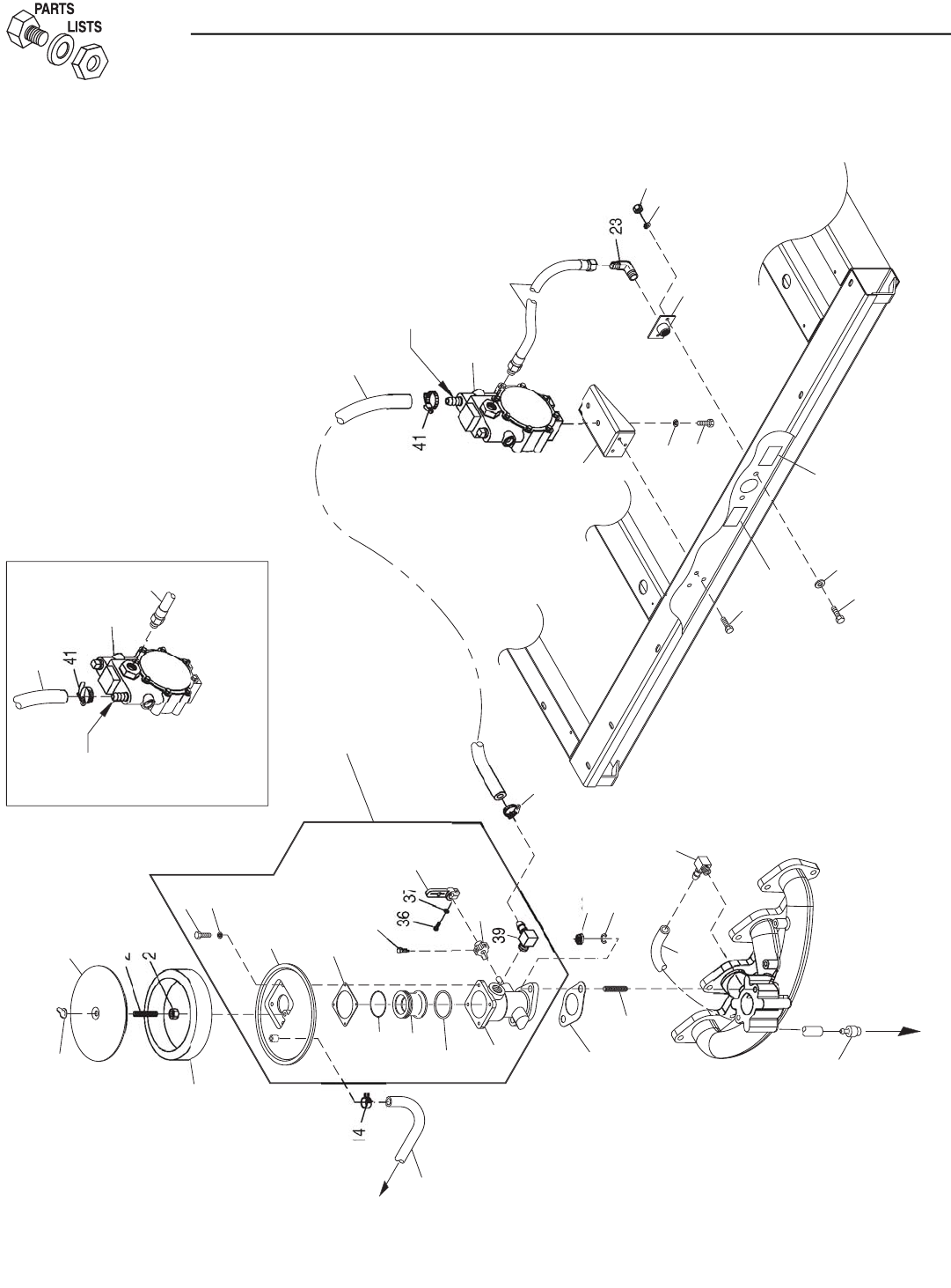
44 Bryant
PO
RT
"OU
T 1"
2
2
7
21
TO
EN
G
INE
10
42
CO
VER
TO
VALVE
12
13
28
1
8
20
33
3
1
3
2
17
3
4
26
6
38
30
16
25
24
18
4
29
15
9
5
27
6
4
C
ARB
U
RET
O
R A
SS
Y.
0
E1028A
(
I/N 19
)
CO
NVER
S
I
O
N
35
41
"OU
T 2"
PO
RT
L
.P. VAP
O
R
3
40
1
11
3
40
7
2
6
11
Section 8 - Exploded Views and Parts
Bryant Liquid-cooled 25 kW Generator
Fuel System — Drawing No. 0E9980-D

Bryant 45
ITEM PART NO. QTY. DESCRIPTION
1 0E8456 1 BRACKET FUEL REGULATOR
2 075580 1 FLANGE FUEL INLET
3 0E9967 1 ASSY FUEL REG 2.5L FRD N/G-L/P
4 039253 4 SCREW HHC M8-1.25 X 20 G8.8
5 022145 2 WASHER FLAT 5/16 ZINC
6 022129 6 WASHER LOCK M8-5/16
7 045771 2 NUT HEX M8-1.25 G8 YEL CHR
8 * 0F1570 1 BODY CARBURETOR ASSEMBLY
9 0A6344 1 BARBED EL 90 1/8 NPT X 3/8
10 0F3994 REF. PCV VALVE 2.5L FORD
11 0E1056 1 FUEL HOSE ASSM. NAT. GAS/L.P.V.
12 0F0397 1 HOSE CRANKCASE BREATHER
13 0A5547 1 COVER AIR CLEANER
14 048031C 2 CLAMP HOSE BAND 1/4
15 0D1509 1 DECAL INLET PRESSURE
16 * 0E0591 1 ADAPTER CARB. TO AIR CLNR
17 059402 1 FILTER ELEMENT
18 037561 1 NUT WING 1/4-20 NYLK
19 0E1028A 1 CARBURETOR ASSY. 2.5L FORD
20 059401 1 CARBURETOR GASKET
21 * 091526 4 SCREW PPHM M5-0.8 X 12 ZNC
22 * 049226 4 WASHER LOCK M5
23 026307 1 ELBOW 90D STREET 3/4
24 062522 1 STUD TH 1/4-20 X 3 G2 ZNC FULL
25 022127 1 NUT HEX 1/4-20 STEEL
26 022259 2 NUT HEX 5/16-18 STEEL
27 050279 1 DECAL FUEL INLET NG
28 0A6125 2 STUD 5/16-18 X 1.25 F THR
29 0C2454 3 SCREW TH-FRM M6-1 X 16 N WA Z/JS
30* 0E1104 1 GASKET, AIR CLEANER ADAPTER
31* 0E0668 1 O-RING 2-028 1.38 X 1.50 X .06
32* 0E0590A 1 VENTURI 20MM
33* 0C5133 1 0-RING 29.82 X 2.62
34* 0E0665 1 SCREW THROTTLE PIN STOP
35* 0E1108 1 THROTTLE ARM REWORK
36* 033138 1 SCREW HHM #10-32 X 5/8
37* 022152 1 WASHER LOCK #10
38* 0E0645 1 LEVER,THROTTLE STOP
39* 034339 1 BARBED EL 90 3/8 NPT X 5/8
40 059194 1 HOSE 5/8 ID LPG & NG (24" LG)
41 057823 2 CLAMP HOSE #10 .56 - 1.06
42 0F0382 1 HOSE 3/8" 90 DEG 2.5L PVC
* INCLUDED IN ITEM 19 (CARBURETOR ASSY )
Section 8 - Exploded Views and Parts
Bryant Liquid-cooled 25 kW Generator
Fuel System — Drawing No. 0E9980-D
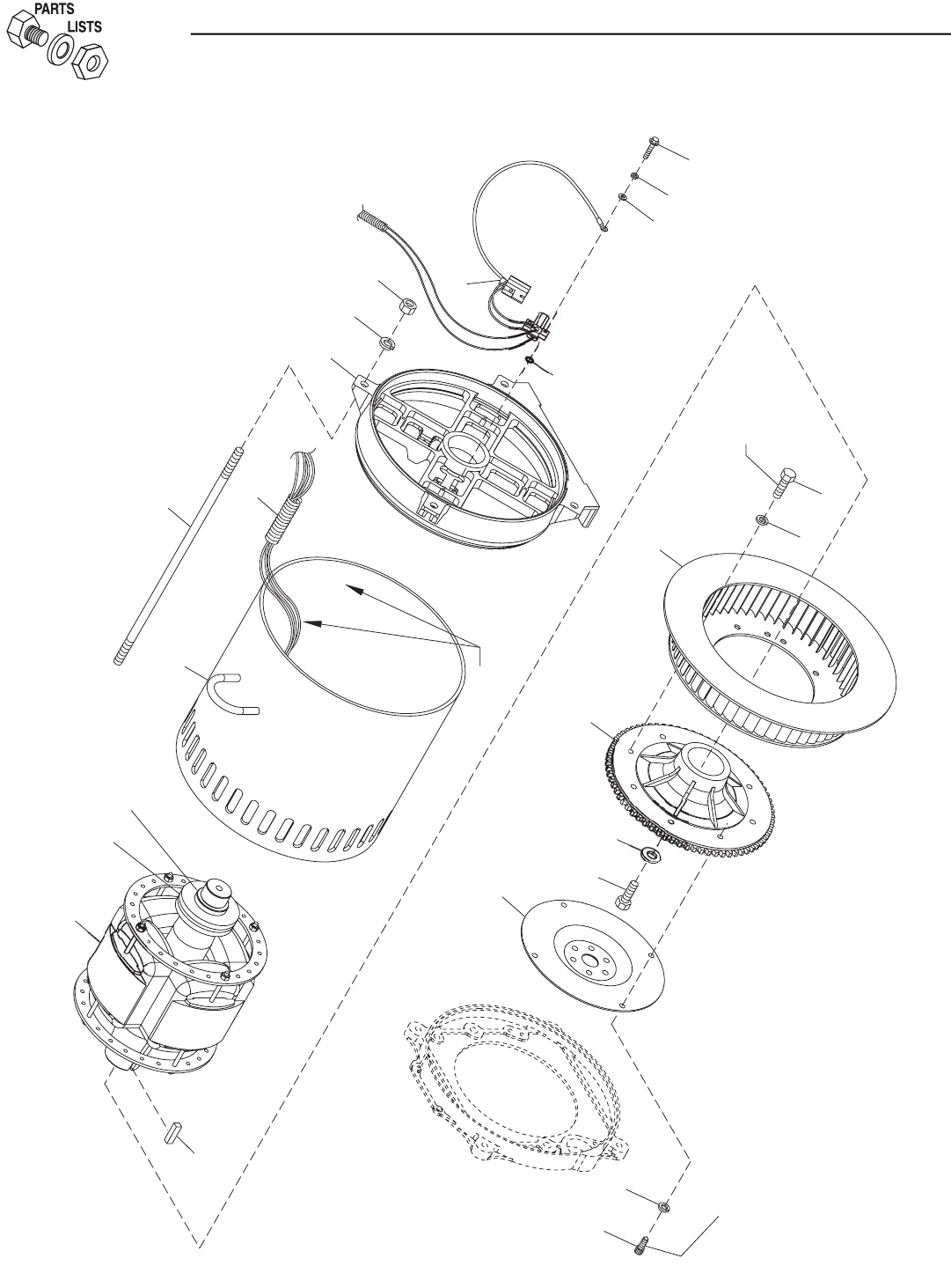
46 Bryant
3
LOC
KTI
G
HT
LOC
KTI
G
HT
7
1
5
17
8
7
6
18
4
16
L
EAD
S
5
2
9
13
21
19
20
14
10
11
12
30
1
3
1
Section 8 - Exploded Views and Parts
Bryant Liquid-cooled 25 kW Generator
Alternator — Drawing No. 0F5092

Bryant 47
ITEM PART NO. QTY. DESCRIPTION
1 0F1659A 1 ROTOR 390 15KW 1P DIRECT HSB (2.5L FORD)
0F1657A 1 ROTOR 390 20KW 1P DIRECT HSB (2.5L FORD)
0F1655A 1 ROTOR 390 25KW 1P DIRECT HSB (2.5L FORD)
0F5073A 1 ROTOR 390__30AD1 HSB TECUM
2 0F1660A 1 STR 390 15AD HSB (382MM LONG) (2.5L FORD)
0F1658A 1 STR 390 20AD HSB (382MM LONG) (2.5L FORD)
0F1656A 1 STR 390 25AD HSB (382MM LONG) (2.5L FORD)
0F5074A 1 STR-390__30AD1 HSB TECUM
3 0E5706 1 REAR BEARING CARRIER 390/DRCT
4 0E5048 REF FLEXPLATE 3.0L FORD
0E5048B REF FLEXPLATE 2.5L FORD
5 0E6668 1 FLYWHEEL ASSY 3.0L HSB LG GEAR
6 0E6076 1 REVCOR FAN 10.75 X 2 W/PRESS DIS
7 046526 8 WASHER LOCK M10
8 051755 4 SCREW HHC M10-1.5 X 16 G8.8
9 04576100BK 4 STUD M14-2.0 X 490 G5 ZINC (3.0L FORD & 2.5L FORD)
10 043123 4 WASHER LOCK M14
11 051779 4 NUT HEX M14-2.0 G8 YEL CHR
12 0E7587 1 ASSY BRUSH HOLDER 390/HSB
13 023365 1 WASHER SHAKEPROOF INT #8
14 0C3993 4 SCREW HHTT M4-0.7 X 25 BP
15 057192 4 SCREW SHC M10-1.5 X 30 G12.9
16 0A2602 1 WASHER FLAT .688 ID X 3.25 OD
17 042558 1 KEY SQ 3/8 X 1 STEEL
18 0A2601 1 SCREW HHC M16-2.0 X 45 G8.8
19 022264 4 WASHER LOCK #8-M4
20 038150 4 WASHER FLAT #8 ZINC
21 077043F 1 CONDUIT FLEX 1-1/4" (30" LG - 3.0L FORD & 3.9L CHRYSLER)
077043F 1 CONDUIT FLEX 1-1/4" (18" LG - 2.5L FORD)
ROTOR REPLACEMENT PARTS
30 047248 1 BALL BEARING-45 MM
31 070892 1 SLIP RING -MACHINED-
Section 8 - Exploded Views and Parts
Bryant Liquid-cooled 25 kW Generator
Alternator — Drawing No. 0F5092
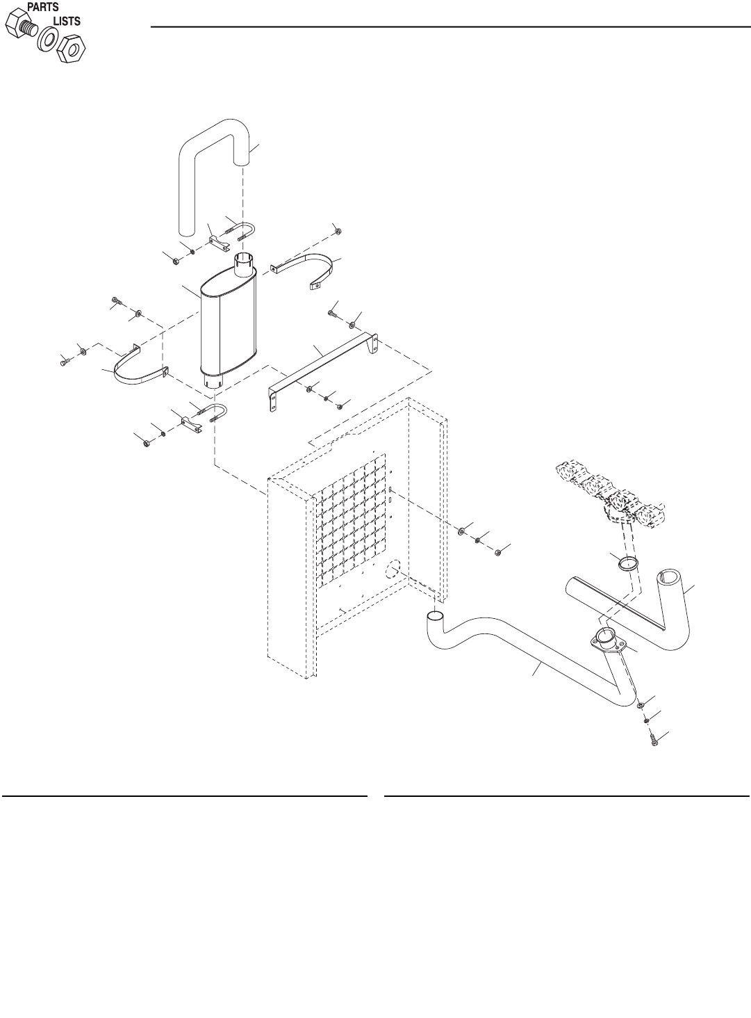
ITEM PART NO. QTY. DESCRIPTION
1 0F2912 1 PIPE MUFFLER OUT
2 0F2869 1 PIPE EXHAUST 2.5L FORD
3 0F2823 1 MUFFLER 2.5L FORD
4 036434 2 BOLT U 5/16-18 X 2.09
5 036449 2 SADDLE 2 INCH
6 022129 6 WASHER LOCK M8-5/16
7 022259 4 NUT HEX 5/16-18 STEEL
8 0E0170A 1 EXHAUST BLANKET 938MM
9 044149 1 GASKET EXHAUST RING
10 0E8816 1 EXHAUST FLANGE 2" PIPE
11 0F2925 2 STRAP MUFFLER
12 0F2926 1 BRACKET, MUFFLER
ITEM PART NO. QTY. DESCRIPTION
13 047411 4 SCREW HHC M6-1.0 X 16 G8.8
14 022097 4 WASHER LOCK M6-1/4
15 022473 8 WASHER FLAT 1/4-M6 ZINC
16 049813 4 NUT HEX M6 X 1.0 G8 YEL CHR
17 039253 2 SCREW HHC M8-1.25 X 20 G8.8
18 045771 2 NUT HEX M8-1.25 G8 YEL CHR
19 0A4010 1 SCREW HHC M8-1.25 X 60 G8.8 FT
20 022145 5 WASHER FLAT 5/16-M8 ZINC
21 022131 2 WASHER FLAT 3/8-M10 ZINC
22 085917 2 WASHER LOCK 3/8 SS
23 0D2611 2 SCREW HHC 3/8-16 X 1-3/4 SS
24 052858 1 NUT TOP LOCK FL M8-1.25
48 Bryant
17
1
9
2
0
11
7
6
4
5
7
2
0
3
6
5
2
12
4
2
0
1
8
6
1
5
1
3
24
11
1
1
6
1
5
14
9
8
22
21
1
0
2
3
Section 8 - Exploded Views and Parts
Bryant Liquid-cooled 25 kW Generator
Muffler — Drawing No. 0F2930-B
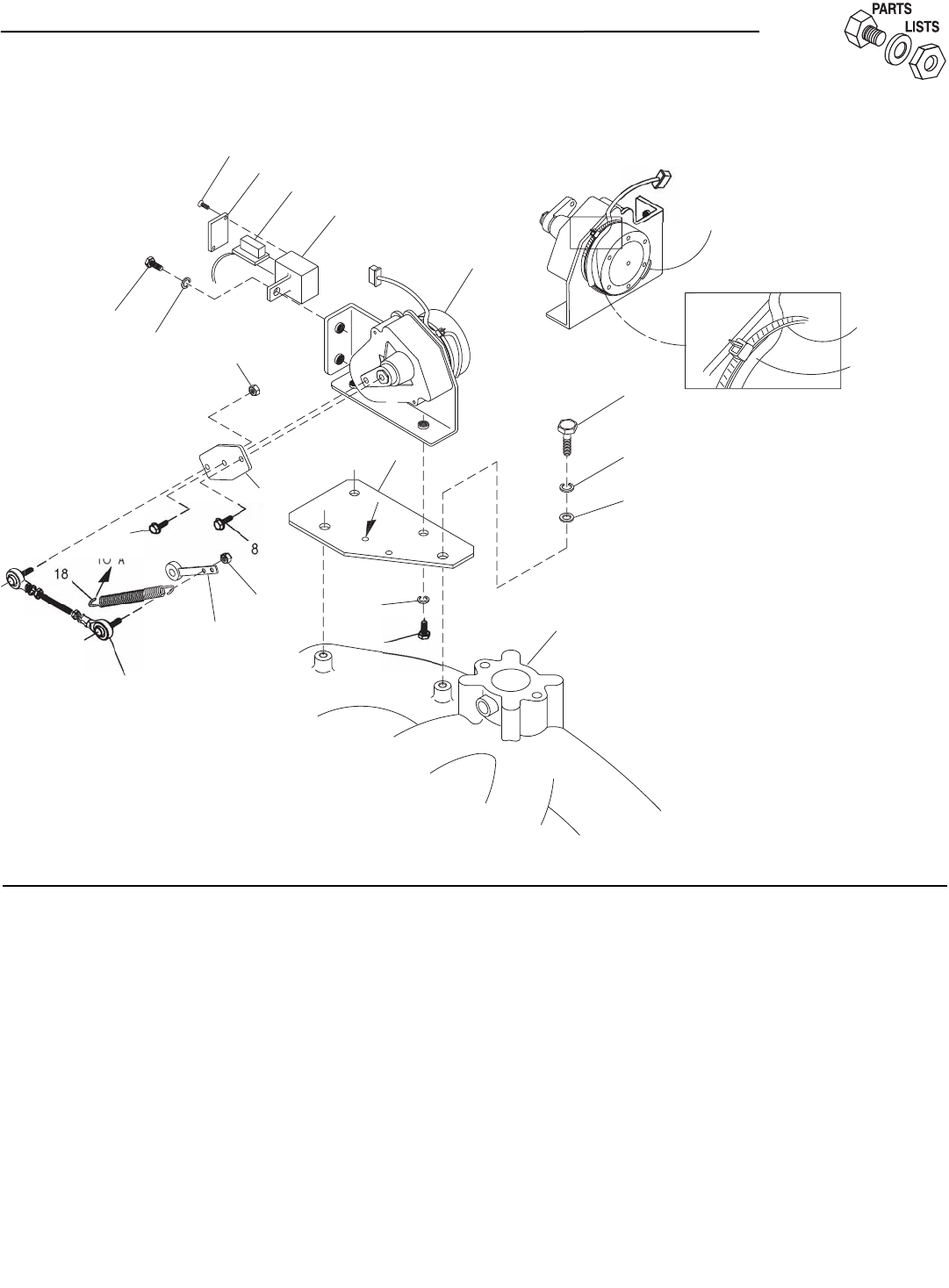
ITEM PART NO. QTY. DESCRIPTION
1 098290 1 ASM MOTOR STEPPER
2 098941A 1 HOUSING GOVERNOR CONNECTOR
3 0F0454 REF HARN GOV 2.5L FORD
4 098942A 1 COVER CONNECTOR HOUSING
5 098225 2 SCREW PFHST #2 X 5/8
6 043146 3 SCREW HHC M6-1.0 X 10 G8.8
7 022097 5 WASHER LOCK M6-1/4
8 0E7358 REF SCREW PPPH HI-LO #4-24 X 3/8
9 098783 1 LEVER STEPPER MOTOR
10 037398 2 NUT LOCK HEX #10-32 NYL INS
11 0E1326 1 ASSY. CARBURETOR LINKAGE ROD
12 0A7106 1 BRACKET STEPPER MOTOR
13 074031 AR LIQUID NEOPRENE
14 029333A 1 TIE WRAP 7.4"X.19" BLK UL
15 022507 2 SCREW HHC 1/4-20 X 1/2 G5
16 022473 2 WASHER FLAT 1/4 ZINC
17 064526 1 SCREW TAP HWH #6-25 X 3/8 ZINC
18 0E1694 1 SPRING,ANTI LASH
ITEM
(
13
)
NEOPREN
E
SECURE WIRE HARNES
S
WITH TIE WRAP A
S
S
H
O
WN
.
C
ARB
U
RET
O
R AR
M
(
REF.
)
11
TO
"
A"
17
6
7
9
1
0
1
0
5
4
(
REF.
)
6
12
"
A"
7
2
3
1
INTAKE MANIF
O
L
D
1
6
7
1
5
CO
ATIN
G
WIRE HARNE
SS
14
Section 8 - Exploded Views and Parts
Bryant Liquid-cooled 25 kW Generator
Stepper Motor — Drawing No. 0E9979-C
Bryant 49
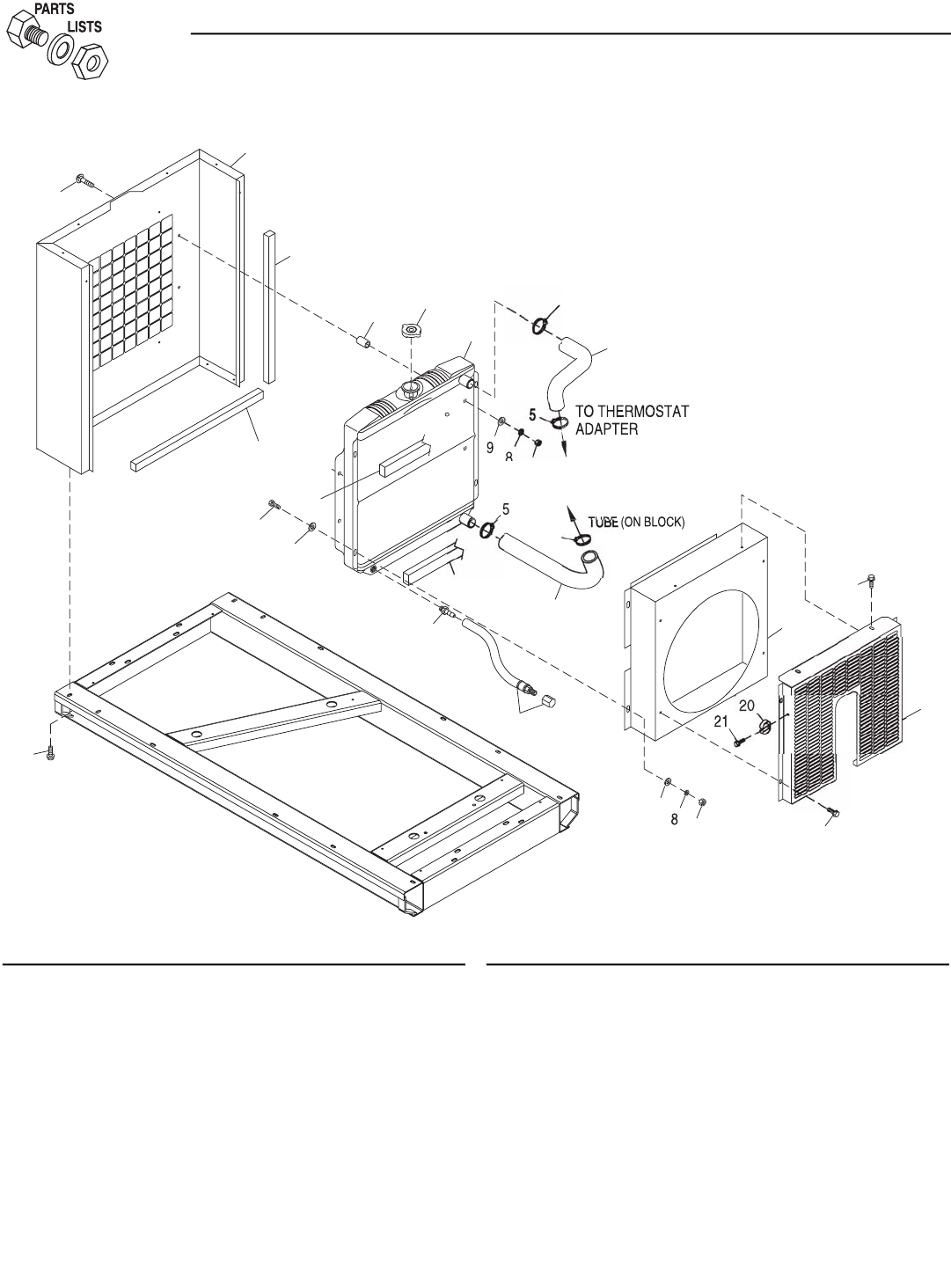
50 Bryant
ITEM PART NO. QTY. DESCRIPTION
1 0E9769 REF SUPPORT,RADIATOR 2.5L FORD
0F0779 REF SUPPORT RADIATOR 2.5L AL
2 0E9837 1 RADIATOR, 2.5L FORD
3 0F0123 1 VENTURI, 16" FAN 2.5L FORD
4 0F0118 1 GUARD, FAN 2.5L FORD
5 099502 4 CLAMP HOSE #24 B1.06-2.00
6 0C2454 REF. SCREW THF M6-1X16 N WA Z/JS
7 052250 2 TAPE FOAM 1 X 1(17"LG)
8 022097 8 WASHER LOCK M6-1/4
9 022473 12 WASHER FLAT 1/4 ZINC
10 022127 8 NUT HEX 1/4-20 STEEL
11 046627 1 CAP RADIATOR
12 060035 4 SPACER .41 X .75 X .87 ST/ZNC
ITEM PART NO. QTY. DESCRIPTION
14 0F0127 1 HOSE, UPPER RADIATOR 174MM
TAL
15 0E9833 1 HOSE, 2.5L FORD LOWER
RADIATOR
16 035461 1 BARBED STR 1/4NPT X 3/8
17 069860C 1 HOSE OIL DRAIN ASSY 21"
18 0A7275 4 FOAM 1.5 X 1 ADHESIVE BACKING
(21.5" LG)
19 031669 4 BOLT CARR 1/4-20 X 1-3/4 JS500
20 065852 1 SPRING CLIP HOLDER .37-.62
21 0A2111 1 SCREW SWAGE 10-32 X 5/16 Z/YC
24 0C2454 6 SCREW TH-FRM M6-1X16 N WA Z/JS
25 022287 4 SCREW HHC 1/4-20 X 3/4 G5
2
5
6
1
9
1
6
17
9
1
0
8
12
7
9
1
8
1
8
1
7
11
2
WATER INLET
T
O
BA
S
E
OF
1
5
5
1
0
5
14
24
4
24
3
Section 8 - Exploded Views and Parts
Bryant Liquid-cooled 25 kW Generator
Radiator — Drawing No. 0E9965-D
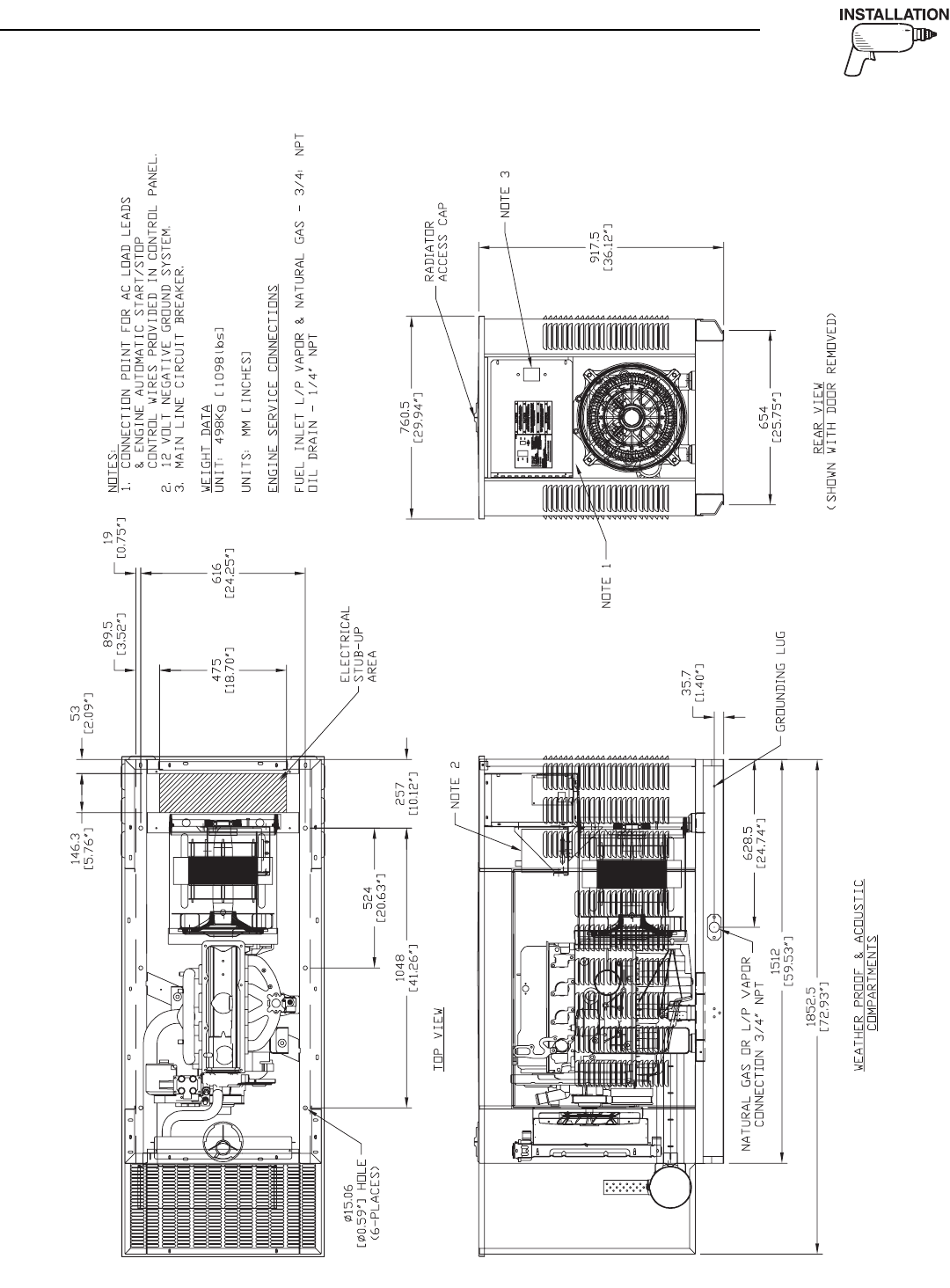
Bryant 51
Section 9 — Installation Diagram
Bryant Liquid-cooled 25 kW Generator
Installation Diagram — Drawing No. 0F1020-A

52 Bryant
Section 10 – Warranty
Bryant Liquid-cooled 25 kW Generator
CALIFORNIA EMISSION CONTROL WARRANTY STATEMENT
YOUR WARRANTY RIGHTS AND OBLIGATIONS
The California Air Resources Board (CARB) and Generac Power Systems, Inc. (Generac) are pleased to explain the Emission
Control System Warranty on your new engine.*In California, new utility, and lawn and garden equipment engines must be
designed, built and equipped to meet the state’s stringent anti-smog standards. Generac will warrant the emission control
system on your engine for the periods of time listed below provided there has been no abuse, neglect, unapproved modifi-
cation or improper maintenance of your engine.
Your emission control system may include parts such as the carburetor, ignition system and exhaust system. Generac will
repair your engine at no cost to you for diagnosis, replacement parts and labor, should a warrantable condition occur.
MANUFACTURER’S EMISSION CONTROL SYSTEM WARRANTY COVERAGE:
Emissions control systems on 1995 and later model year engines are warranted for two years as hereinafter noted. If, dur-
ing such warranty period, any emission-related component or system on your engine is found to be defective in materials or
workmanship, repairs or replacement will be performed by a Generac Authorized Warranty Service Facility.
PURCHASER’S/OWNER’S WARRANTY RESPONSIBILITIES:
As the engine purchaser/owner, you are responsible for the completion of all required maintenance as listed in your factory
supplied Owner’s Manual. For warranty purposes, Generac recommends that you retain all receipts covering maintenance
on your engine. However, Generac cannot deny warranty solely due to the lack of receipts or for your failure to ensure the
completion of all scheduled maintenance.
As the engine purchaser/owner, you should, however, be aware that Generac may deny any and/or all warranty coverage or
responsibility if your engine, or a part/component thereof, has failed due to abuse, neglect , improper maintenance or unap-
proved modifications, or the use of counterfeit and/or “grey market” parts not made, supplied or approved by Generac.
Warranty service can be arranged by contacting Generac Power Systems, Inc..
IMPORTANT NOTE: This warranty statement explains your rights and obligations under the Emission Control System
Warranty (ECS Warranty), which is provided to you by Generac pursuant to California law. See also the “Bryant Two Year
Limited Warranty for Prepackaged Emergency Automatic Standby Generators” which is enclosed herewith on a separate
sheet, also provided to you by Generac. The ECS Warranty applies only to the emission control system of your new engine.
If there is any conflict in terms between the ECS Warranty and the Bryant Warranty, the ECS Warranty shall apply except in
circumstances where the Generac Warranty may provide a longer warranty period. Both the ECS Warranty and the Bryant
Warranty describe important rights and obligations with respect to your new engine.
Warranty service can be performed only by a Generac Authorized Warranty Service Facility. When requesting warranty serv-
ice, evidence must be presented showing the date of the sale to the original purchaser/owner.
To arrange for emissions equipment warranty or if you have any questions regarding your warranty rights and respon-
sibilities, you should contact Generac at the following address:
ATTENTION WARRANTY DEPARTMENT
GENERAC POWER SYSTEMS, INC.
P.O. BOX 297
WHITEWATER, WI 53190
www.generac.com
Part 1

Bryant 53
EMISSION CONTROL SYSTEM WARRANTY
Emission Control System Warranty (ECS Warranty) for 1995 and later model year engines:
(a) Applicability: This warranty shall apply to 1995 and later model year engines. The ECS Warranty Period shall begin on
the date the new engine or equipment is purchased by/delivered to its original, end-use purchaser/owner and shall con-
tinue for 24 consecutive months thereafter.
(b) General Emissions Warranty Coverage: Generac warrants to the original, end-use purchaser/owner of the new engine or
equipment and to each subsequent purchaser/owner that each of its engines is ...
(1) Designed, built and equipped so as to conform with all applicable regulations adopted by the CARB pursuant to its
authority, and
(2) Free from defects in materials and workmanship which, at any time during the ECS Warranty Period, may cause a war-
ranted emissions-related part to fail to be identical in all material respects to the part as described in the engine man-
ufacturer’s application for certification.
(c) The ECS Warranty only pertains to emissions-related parts on your engine, as follows:
(1) Any warranted, emissions-related parts that are not scheduled for replacement as required maintenance in the Owner’s
Manual shall be warranted for the ECS Warranty Period. If any such part fails during the ECS Warranty Period, it shall
be repaired or replaced by Generac according to Subsection (4) below. Any such part repaired or replaced under the
ECS Warranty shall be warranted for the remainder of the ECS Warranty Period.
(2) Any warranted, emissions-related part that is scheduled only for regular inspection as specified in the Owner’s Manual
shall be warranted for the ECS Warranty Period. A statement in such written instructions to the effect of “repair or
replace as necessary” shall not reduce the ECS Warranty Period. Any such part repaired or replaced under the ECS
Warranty shall be warranted for the remainder of the ECS Warranty Period.
(3) Any warranted, emissions-related part that is scheduled for replacement as required maintenance in the Owner’s
Manual shall be warranted for the period of time prior to the first scheduled replacement point for that part. If the part
fails prior to the first scheduled replacement, the part shall be repaired or replaced by Generac according to Subsection
(4) below. Any such emissions-related part repaired or replaced under the ECS Warranty shall be warranted for the
remainder of the ECS Warranty Period prior to the first scheduled replacement point for such emissions-related part.
(4) Repair or replacement of any warranted, emissions-related part under this ECS Warranty shall be performed at no
charge to the owner at a Generac Authorized Warranty Service Dealer.
(5) When the engine is inspected by a Generac Authorized Warranty Service Dealer, the owner shall not be held responsi-
ble for diagnostic costs if the repair is deemed warrantable.
(6) Generac shall be liable for damages to other original engine components or approved modifications proximately caused
by a failure under warranty of any emission-related part covered by the ECS Warranty.
(7) Throughout the ECS Warranty Period, Generac shall maintain a supply of warranted emission-related parts sufficient
to meet the expected demand for such emission-related parts.
(8) Any Generac authorized and approved emission-related replacement part may be used in the performance of any ECS
Warranty maintenance or repairs and will be provided without charge to the owner. Such use shall not reduce Generac
ECS Warranty obligations.
(9) Unapproved, add-on, modified, counterfeit and/or “grey market” parts may not be used to modify or repair a Generac
engine. Such use voids this ECS Warranty and shall be sufficient grounds for disallowing an ECS Warranty claim.
Generac shall not be held liable hereunder for failures of any warranted parts of a Generac engine caused by the use of
such an unapproved, add-on, modified, counterfeit and/or “grey market” part.
EMISSION RELATED PARTS INCLUDE THE FOLLOWING:
*Generac engine types covered by this warranty statement include the following:
1) Prepackaged Standby Generator
2) Auxiliary Power Unit (APU) Generator
3) Standby Generator
Part 2
Section 10 – Warranty
Bryant Liquid-cooled 25 kW Generator
1) Fuel Metering System:
1.2) LPG/Natural Gas carburetion assembly and its internal
components.
a) Fuel controller (if so equipped)
b) Mixer and its gaskets (if so equipped)
c) Carburetor and its gaskets (if so equipped)
d) Primary gas regulator (if so equipped)
e) LP liquid vaporizer (if so equipped)
2) Air Induction System including:
a) Intake pipe/manifold
b) Air cleaner
3) Ignition System including:
a) Spark plug
b) Ignition module
4) Catalytic Muffler Assembly (if so equipped) including:
a) Muffler gasket
b) Exhaust manifold
5) Crankcase Breather Assembly including:
a) Breather connection tube

Section 10 – Warranty
Bryant Liquid-cooled 25 kW Generator
BRYANT "TWO YEAR" LIMITED WARRANTY FOR
"PREPACKAGED EMERGENCY AUTOMATIC STANDBY GENERATORS"
For a period of two years from the date of original sale, Bryant warrants that its generator will be free from defects in material and
workmanship for the items and period set forth below. Bryant will, at its option, repair or replace any part which, upon examination,
inspection and testing by a Bryant Dealer, is found to be defective. All transportation costs under the warranty, including return to the
factory, are to be borne and prepaid by the purchaser/owner. This warranty applies only to Bryant prepackaged emergency automatic
standby generators sold and rated for use in "Standby" applications.
WARRANTY SCHEDULE
YEARS ONE AND TWO - 100% (one hundred percent) transferable coverage on Labor and Part(s) listed.
ENGINE - All Components
ALTERNATOR - All Components
TRANSFER SYSTEM - All Components
Steel enclosures are warranted against rusting for the first year of ownership only. Damage caused after receipt of generator is the
responsibility of the owner and is not covered by this warranty. Nicks, scrapes, dents or scratches to the painted enclosure should be
repaired promptly by the owner.
THIS WARRANTY SHALL NOT APPLY TO THE FOLLOWING:
• Bryant generators that utilize non-Bryant replacement parts.
• Bryant generators utilizing non-Bryant automatic transfer switches.
• Any Bryant generators used as rental or trailer mounted applications.
• Units used for prime power in place of existing utility power where utility power is present or in place of utility power where
utility power service does not normally exist.
• Costs of normal maintenance, adjustments, installation and start-up.
• Steel enclosures that are rusting due to the improper installation, location in a harsh or saltwater environment or scratched where
integrity of paint applied is compromised.
• Failures caused by any contaminated fuels, oils, coolants or lack of proper fluid amounts.
• Failures due, but not limited to, accident, misuse, abuse, negligence or improper installation. As with all mechanical devices, the
Bryant engines need periodic part(s) service and replacement to perform well.
• Failures caused by any external cause or act of God, such as collision, theft, vandalism, riot or wars, nuclear holocaust, fire,
freezing, lightning, earthquake, windstorm, hail, volcanic eruption, water or flood, tornado or hurricane.
• Damage related to rodent and/or insect infestation.
• Products that are modified or altered in a manner not authorized by Bryant in writing.
• Any incidental, consequential or indirect damages caused by defects in materials or workmanship, or any delay in repair or
replacement of the defective part(s).
• Failure due to misapplication.
• Telephone, cellular phone, facsimile, internet access or other communication expenses.
• Living or travel expenses of person(s) performing service, except as specifically included within the terms of a specific unit warranty
period.
• Expenses related to "customer instruction" or troubleshooting where no manufacturing defect is found.
• Rental equipment used while warranty repairs are being performed.
• Costs incurred for equipment used for removal and/or reinstallation of generator, (i.e.; cranes, hoists, lifts, etc.)
• Overnight freight costs for replacement part(s).
• Overtime labor.
• Starting batteries, fuses, light bulbs and engine fluids.
THIS WARRANTY IS IN PLACE OF ALL OTHER WARRANTIES, EXPRESSED OR IMPLIED. SPECIFICALLY,
BRYANT MAKES NO OTHER WARRANTIES AS TO THE MERCHANTABILITY OR FITNESS FOR A PARTICULAR PURPOSE.
Some states do not allow limitations on how long an implied warranty lasts, so the above limitation may not apply to you.
BRYANT 'S ONLY LIABILITY SHALL BE THE REPAIR OR REPLACEMENT OF PART(S) AS STATED ABOVE. IN NO EVENT SHALL
BRYANT BE LIABLE FOR ANY INCIDENTAL OR CONSEQUENTIAL DAMAGES, EVEN IF SUCH DAMAGES ARE A DIRECT
RESULT OF BRYANT 'S NEGLIGENCE. Some states do not allow the exclusion or limitation of incidental or consequential damages,
so the above limitation may not apply to you.
This warranty gives you specific legal rights. You also have other rights from state to state.
Revision (10/01/04)
Part No. 0F4248 Rev. 0 (01/19/05) Printed in U.S.A.
Catalog No. 13AS-PA6 Form No. OM18-3
