Bryant R 22 Users Manual
R-22 to the manual 8c34cd3d-c926-4848-bf69-5d104cfed8ef
2015-02-02
: Bryant Bryant-R-22-Users-Manual-411794 bryant-r-22-users-manual-411794 bryant pdf
Open the PDF directly: View PDF ![]() .
.
Page Count: 52

NOTE: Read the entire instruction manual before starting the
installation.
This symbol →indicates a change since the last issue.
TABLE OF CONTENTS
SAFETY CONSIDERATIONS.....................................................1
INTRODUCTION..........................................................................2
INSTALLATION GUIDELINE ....................................................2
Residential New Construction..................................................2
Add-On Replacement (Retrofit)...............................................2
Seacoast (For Air Conditioners Only) .....................................2
ACCESSORY DESCRIPTIONS...................................................2
Compressor Crankcase Heater..................................................2
Evaporator Freeze Thermostat..................................................2
Winter Start Control .................................................................2
Compressor Start Assist—PTC ................................................2
Compressor Start Assist Capacitor/Relay ................................2
Low-Ambient Controller ..........................................................2
MotorMaster™ Control ............................................................2
Low-Ambient Pressure Switch.................................................2
Wind Baffle...............................................................................3
Coastal Filter.............................................................................3
Support Feet..............................................................................3
Liquid-Line Solenoid Valve.....................................................3
Thermostatic-Expansion Valve.................................................3
Isolation Relay ..........................................................................3
LOW-AMBIENT GUIDELINE.....................................................3
LONG-LINE GUIDELINE............................................................3
Approved Systems ....................................................................3
Interconnecting Tubing Sizing .................................................3
Metering Device Sizing............................................................6
Liquid-Line Solenoid And Tubing Configuration...................7
Charging Information................................................................8
2–Speed Applications ...............................................................8
UNIT IDENTIFICATION .............................................................8
Product Number Stamped on Unit-Rating Plate......................8
Serial Number Identification ....................................................9
CABINET.....................................................................................10
Remove Top Cover—Before 1/1/92 ......................................10
Remove Fan-Motor Assembly—Before 1/1/92.....................10
Information Plate—Reliant Products......................................10
Control-Box Cover—Cube Products......................................10
Remove Top Cover— After 1/1/92 .......................................10
Remove Fan-Motor Assembly—After 1/1/92........................11
ELECTRICAL..............................................................................12
Aluminum Wire ......................................................................12
Contactors................................................................................13
Capacitors................................................................................14
Cycle Protector........................................................................15
Crankcase Heater ....................................................................16
Time-Delay Relay...................................................................16
Pressure Switches....................................................................17
Defrost Thermostats................................................................18
Defrost-Control Board ............................................................18
Fan Motors..............................................................................21
Service Alarm Control Board.................................................21
Outdoor Thermostat(s)............................................................22
Compressor Plug.....................................................................24
Low-Voltage Terminals..........................................................25
RECIPROCATING COMPRESSOR ..........................................25
Mechanical Failures................................................................25
Electrical Failures ...................................................................26
System Cleanup After Burnout ..............................................27
Compressor Removal And Replacement ...............................27
COPELAND SCROLL COMPRESSOR ....................................28
Features ...................................................................................28
Troubleshooting ......................................................................28
Discharge Thermostat.............................................................28
Discharge Solenoid Valve ......................................................28
MILLENNIUM SCROLL COMPRESSOR................................29
Features ...................................................................................29
Compressor Protection............................................................29
Troubleshooting ......................................................................29
Scroll Compressor, 3–Phase Monitor.....................................29
TWO-SPEED SYSTEM ..............................................................29
Cautions and Warnings...........................................................29
System Functions....................................................................29
Factory Defaults......................................................................33
Major Components..................................................................33
LED Function/Malfunction Lights.........................................34
Troubleshooting ......................................................................34
REFRIGERATION SYSTEM .....................................................35
Refrigeration Cycle.................................................................35
Leak Detection........................................................................35
Brazing ....................................................................................37
Service Valves ........................................................................38
Check-Flo-Rater™ (Bypass-Type) Heat Pumps Only...........39
Reversing Valve......................................................................39
Thermostatic-Expansion Valves (TXV).................................40
Thermostatic-Expansion Valve (Bi-Flow TXV)....................41
Coil Removal ..........................................................................41
Liquid-Line Strainer (Heat Pumps Only) ..............................41
Accumulator............................................................................43
Contaminant Removal ............................................................43
System Charging.....................................................................43
Checking Charge.....................................................................43
CARE AND MAINTENANCE...................................................45
SAFETY CONSIDERATIONS
Service and repair of these units should be attempted only by
trained service technicians familiar with Bryant standard service
instructions and training manual.
All equipment should be installed in accordance with accepted
practices and unit Installation Instructions, and in compliance with
all national and local codes.
Power should be turned off when servicing or repairing electrical
components. Extreme caution should be observed when trouble-
shooting electrical components with power on. Observe all warn-
ing notices posted on equipment.
Application Guide and
Service Manual
AIR CONDITIONERS AND HEAT PUMPS
USING R-22 REFRIGERANT
Cancels: AP01-3, SM01,02-4 SM01,02-5
10-00
—1—
Refrigeration system contains refrigerant under pressure. Extreme
caution should be observed when handling refrigerants. Wear
safety glasses and gloves to prevent personal injury. During
normal system operation, some components are hot and can cause
burns. Rotating fan blades can cause personal injury. Appropriate
safety considerations are posted throughout this manual where
potentially dangerous techniques are addressed.
It is important to recognize safety information. This is the
safety-alert symbol . When you see this symbol on the unit and
in instructions or manuals, be alert to the potential for personal
injury.
Understand the signal words DANGER, WARNING, and CAU-
TION. These words are used with the safety-alert symbol. DAN-
GER identifies the most serious hazards which will result in severe
personal injury or death. WARNING signifies hazards which
could result in personal injury or death. CAUTION is used to
identify unsafe practices which would result in minor personal
injury or product and property damage. NOTE is used to highlight
suggestions which will result in enhanced installation, reliability,
or operation.
WARNING: Improper installation, adjustment, alter-
ation, service, maintenance, or use can cause explosion,
fire, electrical shock, or other conditions which may
cause personal injury, death, or property damage. Consult
a qualified installer, service agency, or your distributor or
branch for information or assistance. The qualified in-
staller or agency must use factory-authorized kits or
accessories when modifying this product.
INTRODUCTION
This service manual enables a service technician to service, repair,
and maintain a family of similar air conditioners and heat pumps.
It covers standard single-speed products and 2–speed products
only. For variable-speed products, refer to the respective service
manuals.
INSTALLATION GUIDELINE
I. RESIDENTIAL NEW CONSTRUCTION
Specifications for this unit in the residential, new-construction
market require the outdoor unit, indoor unit, refrigerant-tubing
sets, metering device, and filter drier listed in Product Data Sheet
(PDS). DO NOT DEVIATE FROM PDS. Consult unit Installation
Instructions for detailed information.
II. ADD-ON REPLACEMENT (RETROFIT)
Specifications for this unit in the add-on replacement/retrofit
market require change-out of outdoor unit, metering device, and all
capillary-tube coils. Change-out of indoor coil is recommended.
There can be no deviation.
1. If system is being replaced due to compressor electrical
failure, assume acid is in system. If system is being replaced
for any other reason, use approved acid test kit to determine
acid level. If even low levels of acid are detected, install
factory-approved, suction-line filter drier in addition to the
factory-supplied, liquid-line filter drier. Remove the
suction-line filter drier as soon as possible, with a maximum
of 72 hr.
2. Drain oil from low points or traps in suction-line and
evaporator if they were not replaced.
3. Change out indoor coil or verify existing coil is listed in the
Product Data Sheets.
4. Replace outdoor unit.
5. Install liquid-line filter drier.
6. If suction-line filter drier was installed for system clean up,
operate system for 10 hr. Monitor pressure drop across
drier. If pressure drop exceeds 3 psig, replace suction-line
and liquid-line filter driers. Be sure to purge system with
dry nitrogen and evacuate when replacing filter driers.
Continue to monitor pressure drop across suction-line filter
drier. After 10 hr of run time, remove suction-line filter
drier and replace liquid-line filter drier. Never leave
suction-line filter drier in system longer than 72 hr
(actual time).
7. Charge system. (See unit information plate.)
III. SEACOAST (FOR AIR CONDITIONERS ONLY)
Installation of these units in seacoast locations requires the use of
a coastal filter. (See section on cleaning.)
ACCESSORY DESCRIPTIONS
Refer to Table 1 for an Accessory Usage Guide for Air Condi-
tioners and Heat Pumps. See Model-specific product literature for
any kit part number. Refer to the appropriate section below for a
description of each accessory and its use.
I. COMPRESSOR CRANKCASE HEATER
An electric heater which mounts to base of compressor to keep
lubricant warm during off cycles. Improves compressor lubrication
on restart and minimizes chance of refrigerant slugging and oil
pumpout. The crankcase heater may or may not include a
thermostat control. For units equipped with crankcase heaters,
apply power for 24 hr before starting compressor.
II. EVAPORATOR FREEZE THERMOSTAT
An SPST temperature-activated switch stops unit operation when
evaporator reaches freeze-up conditions.
III. WINTER START CONTROL
An SPST delay relay which bypasses the low-pressure switch for
approximately 3 minutes to permit startup for cooling operation
under low-load conditions.
IV. COMPRESSOR START ASSIST—PTC
Solid-state electrical device which gives a ″soft″boost to the
compressor at each start.
V. COMPRESSOR START ASSIST CAPACITOR/RELAY
Start capacitor and start relay gives ″hard″boost to compressor
motor at each start. Required with Liquid-Line Solenoid or
hard-shutoff TXV for all equipment.
VI. LOW-AMBIENT CONTROLLER
Low-ambient controller is a cycle-control device activated by a
temperature sensor mounted on a header tube of the outdoor coil.
It is designed to cycle the outdoor fan motor in order to maintain
condensing temperature within normal operating limits (approxi-
mately 100°F high, and 60°F low). The control will maintain
working head pressure at low-ambient temperatures down to 0°F
when properly installed.
VII. MOTORMASTER™ CONTROL
A fan speed-control device activated by a temperature sensor. It is
designed to control condenser fan-motor speed in response to the
saturated, condensing temperature during operation in cooling
mode only. For outdoor temperature down to -20°F, it maintains
condensing temperature at 100°F±10°F. Requires a ball-bearing
fan motor.
VIII. LOW-AMBIENT PRESSURE SWITCH
A long-life pressure switch which is mounted to outdoor unit
service valve. It is designed to cycle the outdoor fan motor in
response to condenser pressure in cooling mode in order to
maintain head pressure within normal operating limits (approxi-
mately 100 psig to 225 psig). The control will maintain working
head pressure at low-ambient temperatures down to 0°F when
properly installed.
—2—

IX. WIND BAFFLE
A field-fabricated sheet-metal cover used to stop prevailing winds
or where outdoor ambient temperature is less than 55°F during unit
operation of cooling mode.
X. COASTAL FILTER
A mesh screen inserted under top cover and inside base pan to
protect condenser coil from salt damage without restricting air-
flow.
XI. SUPPORT FEET
Four adhesive plastic feet which raise unit 4 in. above mounting
pad. This allows sand, dirt, and other debris to be flushed from unit
base; minimizes corrosion.
XII. LIQUID-LINE SOLENOID VALVE
An electrically operated shutoff valve to be installed at outdoor or
indoor unit (depending on tubing configuration) which stops and
starts refrigerant liquid flow in response to compressor operation.
Maintains a column of refrigerant liquid ready for action at next
compressor-operation cycle and prevents liquid migration during
the off cycle.
XIII. THERMOSTATIC-EXPANSION VALVE
A modulating flow-control device which meters refrigerant flow
rate into the evaporator in response to the superheat of the
refrigerant gas leaving the evaporator. Only use factory-specified
TXV’s.
XIV. ISOLATION RELAY
A DPDT relay which switches the low-ambient controller out of
the outdoor fan-motor circuit when the heat pump switches to
heating mode.
LOW-AMBIENT GUIDELINE
The minimum operating temperature for these units in cooling
mode is 55°F outdoor ambient without additional accessories. This
equipment may be operated in cooling mode at ambient tempera-
tures below 55°F when the accessories listed in Table 1 are
installed. Wind baffles are required when operating in cooling
mode at ambients below 55°F. Refer to Fig. 1 or 2 and Table 2 or
3 for wind baffle construction details.
LONG-LINE GUIDELINE
This Long-Line Application Guideline applies to all Bryant
residential air conditioner and heat pump split systems that have a
nominal capacity of 18,000 to 60,000 Btuh. This guideline
provides required system changes and accessories necessary for
any residential product having piping requirements greater than 50
ft or installations where indoor unit is located above outdoor unit.
This guideline is intended to cover applications outside the
standard Installation Instructions. This guideline is for standard,
single-speed products. For applications involving 2-speed prod-
ucts, refer to Section VI first.
NOTE: The presale literature for outdoor unit must be referred to
in conjunction with this guideline.
I. APPROVED SYSTEMS
Any residential indoor/outdoor unit combination listed in the
outdoor unit presale literature is an approved system, EXCEPT the
following:
•Indoor coils with capillary-metering devices
•All equipment less than nominal 18,000 Btuh
•All 1/4-in. and 5/16–in. liquid-line applications
•Any indoor furnace coil/fan coil not listed in outdoor unit
presale literature
•Any application which has interconnecting tubing with an
equivalent length greater than 175 ft
II. INTERCONNECTING TUBING SIZING
Table 4 lists recommended interconnecting vapor-line diameters
for equivalent total-line lengths. All residential split systems
installed in long-line applications must use only 3/8-in. liquid
lines. Equivalent line length equals the linear length (measured) of
interconnecting vapor tubing plus losses due to elbows. (See Table
5 and Fig. 3.) Liquid lines larger than 3/8-in. OD greatly increase
charge quantity of the system. Excessive charge increases risk of
migration and compressor damage. Table 4 provides the estimated
percentage of nominal cooling-capacity losses based on the stan-
dard, required vapor line size versus what is selected for the
long-line application. Since the vapor line is the discharge line in
heating mode, losses are minimal.
TABLE 1—REQUIRED FIELD-INSTALLED ACCESSORIES FOR AIR CONDITIONERS AND HEAT PUMPS
ACCESSORY
REQUIRED FOR
LOW-AMBIENT
APPLICATIONS
(BELOW 55°F)
REQUIRED FOR
LONG-LINE
APPLICATIONS*
(OVER 50 FT)
REQUIRED FOR
SEA COAST
APPLICATIONS
(WITHIN 2 MILES)
Crankcase Heater Yes Yes No
Evaporator Freeze Thermostat Yes No No
Winter Start Control Yes† No No
Accumulator No No No
Compressor Start Assist
Capacitor and Relay Yes Yes No
Low Ambient Controller,
MotorMaster™Control,
or
Low-Ambient Pressure Switch
Yes No No
Wind Baffle See Low-Ambient Instructions No No
Coastal Filter No No Yes
Support Feet Recommended No Recommended
Liquid-Line Solenoid Valve
or
Hard-Shutoff TXV No See Long-Line
Application
Guideline No
Ball-Bearing Fan Motor Yes‡ No No
Isolation Relay Yes** No No
*For tubing line sets between 50 and 175 ft, refer to Residential Split-System Long-Line Application Guideline.
†Only when low-pressure switch is used.
‡Required for Low-Ambient Controller (full modulation feature) and MotorMaster™ control only.
** Required on Heat Pumps only.
—3—
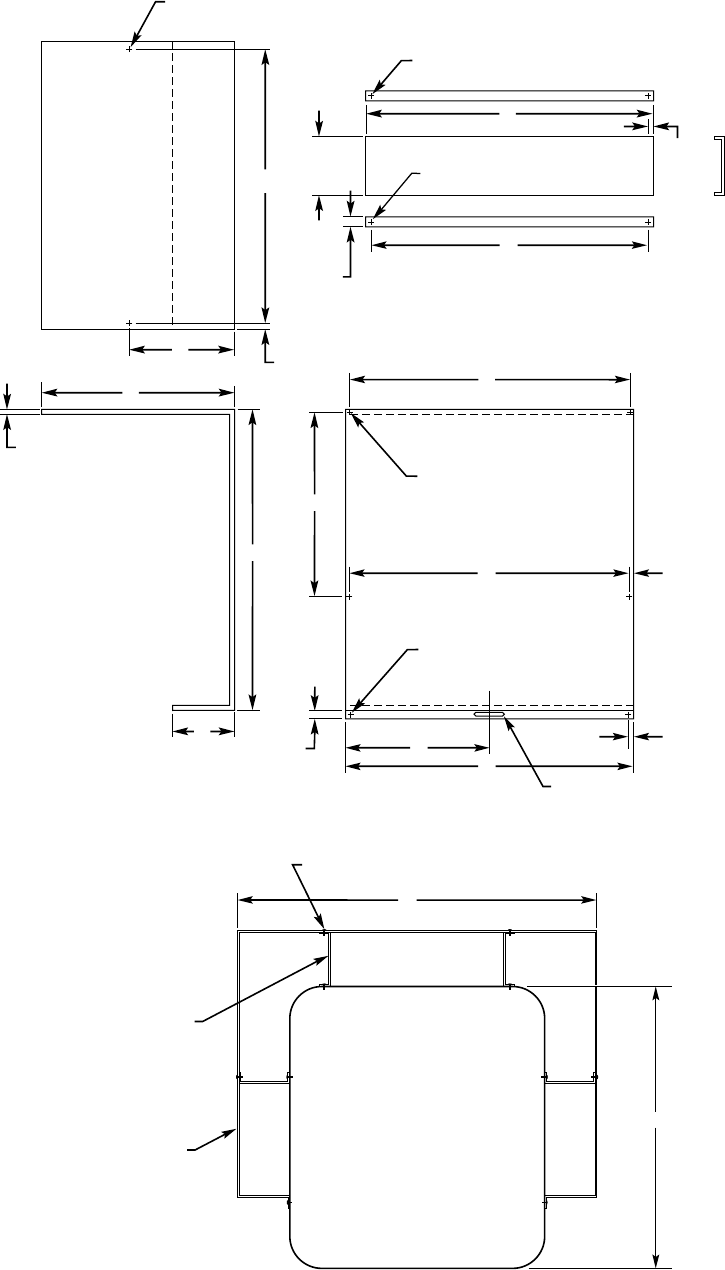
Fig. 1—Wind Baffle Construction for Reliant Units
A95445
1/4″ x 3/8″ (5.56 x 9.53) SLOT
4 REQ'D
1/2″
(12.7)
J
7/16″
(11.6)
C
A
7/16″
(11.6)
B
5 5/16″
(151.5)
1/2″
(12.7)
TYP
H
3/8″
(9.6)
G
J
K
E
F
D
L
1/8″ (3.45) DIA HOLE
1 REQ'D
1/4″ (5.56) DIA HOLE
3 REQ'D
1/4″ x 2″
(5.56 x 50.8) SLOT
1/4″
(6.3)
BAFFLE
MAT'L: 20 GA STEEL
SUPPORT
MAT'L: 18 GA STEEL
1/8″ (3.45) DIA HOLE
2 REQ'D
3/8″ (9.6)
6″
(152.4)
1/4″ (5.56) DIA HOLE 2 REQ'D
OUTDOOR
UNIT
BAFFLE ASSEMBLY
SCREW
10 REQ'D
SUPPORT
4 REQ'D
BAFFLE
2 REQ'D
AA
—4—
Calculate the linear length of vapor tube required, adding any
losses for the total number of elbows for application. (See Table
5.) Using this equivalent length, select desired vapor-line size from
Table 4. Subtract the nominal percentage loss from outdoor-unit
presale-literature Detailed Cooling Capacities data for the given
indoor/outdoor combination. Reference all notes of Table 4.
NOTE: When specifying vapor-line insulation, be aware of the
following standard practice:
All standard accessory-tubing kits are supplied with 3/8-in. insu-
lation on vapor line.
For minimal capacity loss in long-line application, 1/2-in. insula-
tion should be specified.
TABLE 2—WIND BAFFLE DIMENSIONS FOR RELIANT UNITS WITH AEROQUIET-SYSTEM TOP (IN.)
UNIT SIZE AA UNIT HEIGHT A B C D E F G H J K L
Small 26-3/16
23-13/16 17-1/4 24-5/16 10-1/4 19-3/4 20-1/2 34-1/2 19-5/8 20-3/8 19-5/8 0 0
27-13/16 17-1/4 24-5/16 10-1/4 23-3/4 24-1/2 34-1/2 23-5/8 24-3/8 23-5/8 0 11-7/8
33-13/16 17-1/4 24-5/16 10-1/4 29-3/4 30-1/2 34-1/2 29-5/8 30-3/8 29-5/8 0 14-7/8
Medium 33
27-13/16 21 30-5/8 10-1/4 23-3/4 24-1/2 42 23-5/8 24-3/8 23-5/8 17-1/8 11-7/8
33-13/16 21 30-5/8 10-1/4 29-3/4 30-1/2 42 29-5/8 30-3/8 29-5/8 17-1/8 14-7/8
39-13/16 21 30-5/8 10-1/4 35-3/4 36-1/2 42 35-5/8 36-3/8 35-5/8 17-1/8 17-7/8
Large 42-1/16 33-13/16 25-5/16 39-3/4 10-1/4 29-3/4 30-1/2 50-9/16 29-5/8 30-3/8 29-5/8 21-11/16 14-7/8
39-13/16 25-5/16 39-3/4 10-1/4 35-3/4 36-1/2 50-9/16 35-5/8 36-3/8 35-5/8 21-11/16 17-7/8
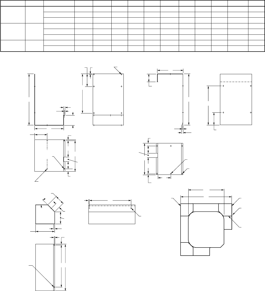
Fig. 2—Wind Baffle Construction for Cube Units
A95446
LEFT
SIDE RIGHT
SIDE
SCREW
14 REQ'D
SUPPORT
3 REQ'D
OUTDOOR
UNIT
BAFFLE ASSEMBLY
1/4″ x 3/8″ (5.56 x 9.53) SLOT
6 REQ'D
13/64″
(5.4)
TYP
SUPPORT
MAT'L: 18 GA STEEL
1/2″
(12.7)
1/4″
(6.4)
B
C
5 3/64″
(128.0)
7 7/8″
(199.9)
D
A 2 1/2″
(63.5)
1 21/32″ (42.1)
1/4″ x 3/8″ (5.56 x 9.53) SLOT
6 REQ'D
1/4″ (5.56) DIA
2 REQ'D
25/64″ (10.0)
E
7 7/8″
(200.0)
3/16″
(4.6)
1/8″ (3.45) DIA
2 REQ'D
BAFFLE - LEFT
MAT'L: 20 GA STEEL
F
C
5 3/64″
(128.0)
1/2″
(12.7)
TYP
E
7 29/32″ (200.8)
BAFFLE - RIGHT
MAT'L: 20 GA STEEL
A
D
1 21/32″ (42.1)
25⁄64″ (10.0)
2 1/2″
(63.5)
G
1/4″ (5.56) DIA
4 REQ'D
JC
AA
H
J
1/4″
(6.4)
23/64″ (9.2)
1/2″ (12.7)
TYP
8 5/64″ (205.3)
TYP
4 57⁄64″
(124.2) TYP
2 5/64″
(52.6)
4 9/64″ (105.2)
45°
TYP
1/8″ (3.45) DIA.
4 REQ'D
1/4″ (5.56) DIA
2 REQ'D
23/64″
(9.2)
—5—
For reference only, the close cell insulation material specified for
accessory tubing kits is a compound of vinyl, neoprene, or nitrile
blends of these polymers. Performance requirements include
thermal range of 0°Fto200°F (-17.8°Cto93°C) and a maximum
thermal conductivity of 0.28.
NOTE: Special consideration must be given to isolating intercon-
necting tubing from building structure. Isolate tubing so that
vibration or noise is not transmitted into structure.
III. METERING DEVICE SIZING
The metering device for a long-line application must be flexible
enough to compensate for frictional losses due to long refrigerant
lines and installed system design (indoor coil above or below
outdoor unit.) The piston or TXV provides such flexibility.
The piston should be changed for both indoor coil and outdoor heat
pump unit, depending on system configuration and line length.
Tables 6 and 7 provide necessary changes for a given application.
Use Tables 6 and 7 when selecting correct piston size. Outdoor-
unit presale literature must be consulted to determine metering
devices specified for standard applications. After determining
standard application piston size(s), refer to Tables 6 and 7 as they
relate to system design (outdoor unit above or below indoor unit)
per equivalent length of tubing.
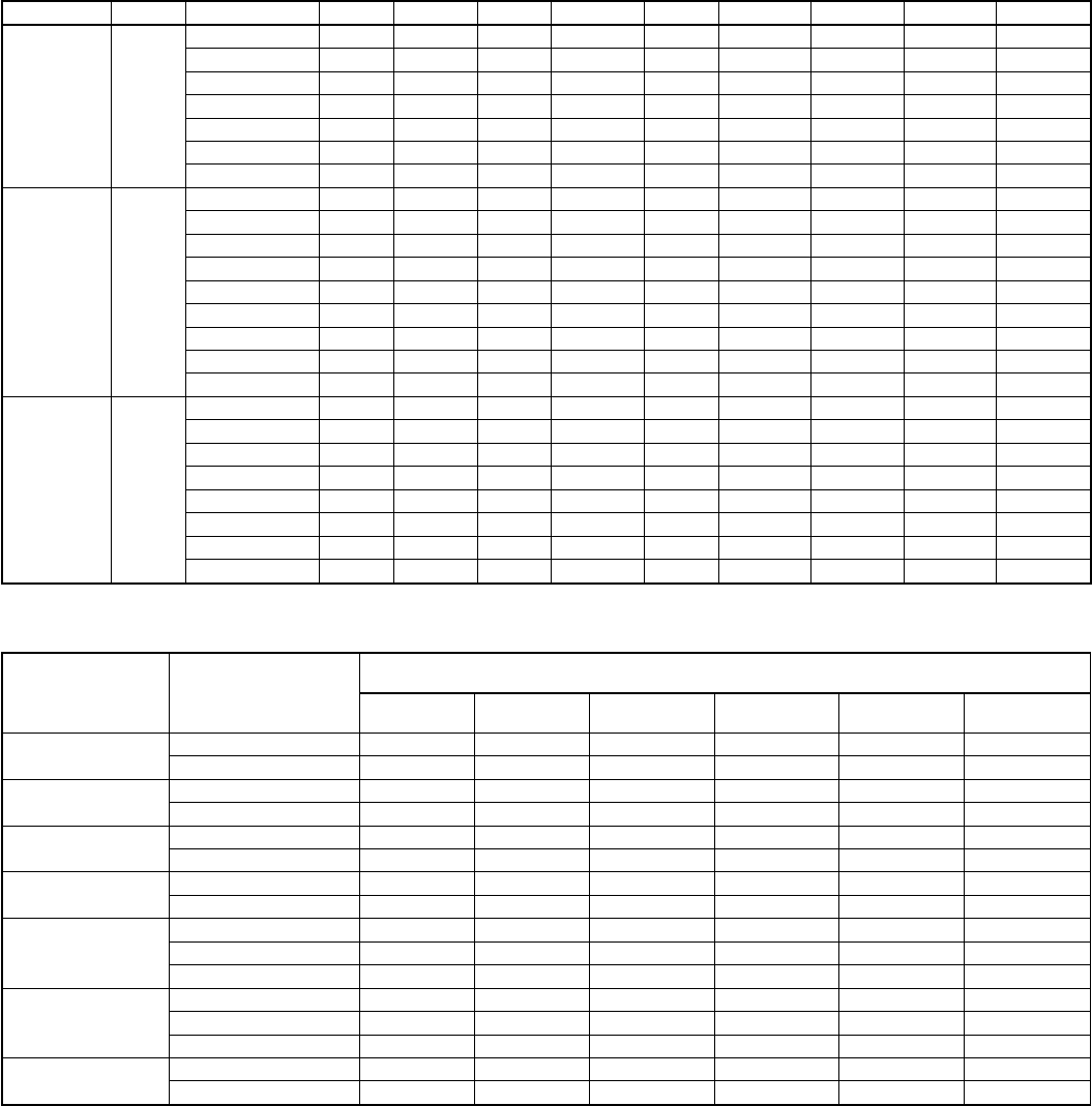
TABLE 3—WIND BAFFLE DIMENSIONS FOR CUBE UNITS (IN.)
UNIT SIZE AA UNIT HEIGHT A B C D E F G H J
Small 18
21-15/16 19-7/8 13-3/4 28-1/8 10-11/16 20-1/4 11-11/16 3-13/16 19-13/16 17-13/16
23-15/16 21-7/8 13-3/4 28-1/8 10-11/16 20-1/4 11-11/16 3-13/16 21-13/16 19-13/16
25-15/16 23-7/8 13-3/4 28-1/8 10-11/16 20-1/4 11-11/16 3-13/16 23-13/16 21-13/16
27-15/16 25-7/8 13-3/4 28-1/8 10-11/16 20-1/4 11-11/16 3-13/16 25-13/16 23-13/16
29-15/16 27-7/8 13-3/4 28-1/8 10-11/16 20-1/4 11-11/16 3-13/16 27-13/16 25-13/16
31-15/16 29-7/8 13-3/4 28-1/8 10-11/16 20-1/4 11-11/16 3-13/16 29-13/16 27-13/16
33-15/16 31-7/8 13-3/4 28-1/8 10-11/16 20-1/4 11-11/16 3-13/16 31-13/16 29-13/16
Medium 22-1/2
21-15/16 19-7/8 18-5/16 32-5/8 10-11/16 24-3/4 16-3/16 8-1/4 19-13/16 17-13/16
23-15/16 21-7/8 18-5/16 32-5/8 10-11/16 24-3/4 16-3/16 8-1/4 21-13/16 19-13/16
25-15/16 23-7/8 18-5/16 32-5/8 10-11/16 24-3/4 16-3/16 8-1/4 23-13/16 21-13/16
27-15/16 25-7/8 18-5/16 32-5/8 10-11/16 24-3/4 16-3/16 8-1/4 25-13/16 23-13/16
29-15/16 27-7/8 18-5/16 32-5/8 10-11/16 24-3/4 16-3/16 8-1/4 27-13/16 25-13/16
31-15/16 29-7/8 18-5/16 32-5/8 10-11/16 24-3/4 16-3/16 8-1/4 29-13/16 27-13/16
33-15/16 31-7/8 18-5/16 32-5/8 10-11/16 24-3/4 16-3/16 8-1/4 31-13/16 29-13/16
35-15/16 33-7/8 18-5/16 32-5/8 10-11/16 24-3/4 16-3/16 8-1/4 33-13/16 31-13/16
37-15/16 35-7/8 18-5/16 32-5/8 10-11/16 24-3/4 16-3/16 8-1/4 35-13/16 33-13/16
Large 30
25-15/16 23-7/8 25-3/4 40-1/8 10-11/16 32-1/4 23-11/16 15-13/16 23-13/16 21-13/16
27-15/16 25-7/8 25-3/4 40-1/8 10-11/16 32-1/4 23-11/16 15-13/16 25-13/16 23-13/16
29-15/16 27-7/8 25-3/4 40-1/8 10-11/16 32-1/4 23-11/16 15-13/16 27-13/16 25-13/16
31-15/16 29-7/8 25-3/4 40-1/8 10-11/16 32-1/4 23-11/16 15-13/16 29-13/16 27-13/16
33-15/16 31-7/8 25-3/4 40-1/8 10-11/16 32-1/4 23-11/16 15-13/16 31-13/16 29-13/16
35-15/16 33-7/8 25-3/4 40-1/8 10-11/16 32-1/4 23-11/16 15-13/16 33-13/16 31-13/16
37-15/16 35-7/8 25-3/4 40-1/8 10-11/16 32-1/4 23-11/16 15-13/16 35-13/16 33-13/16
39-15/16 37-7/8 25-3/4 40-1/8 10-11/16 32-1/4 23-11/16 15-13/16 37-13/16 35-13/16
TABLE 4—ESTIMATED PERCENTAGE OF NOMINAL COOLING-CAPACITY LOSSES*
UNIT
NOMINAL
SIZE
(BTUH)
LONG-LINE
VAPOR-LINE
DIAMETER
(IN.)†
EQUIVALENT LINE LENGTH (FT)
50 75 100 125 150 175
18,000 5/8 5 7 9 12 12 14
3/4 1 3 4 5 5 7
24,000 5/8 6 9 13 16 19 22
3/4 0 1 1 2 3 4
30,000 5/8 6 8 10 13 15 17
3/4 2 3 4 5 6 7
36,000 3/4 7 10 14 17 21 N/R
7/8 2 4 6 8 10 11
42,000
3/4 7 10 13 17 20 23
7/8 3 4 6 7 8 10
1-1/8 0 0 1 1 2 2
48,000
3/4 10 14 18 22 N/R N/R
7/8 4 6 7 9 11 13
1-1/8 0 0 1 1 2 2
60,000 7/8 7 9 11 14 16 19
1-1/8 1 2 2 3 3 4
*The estimated percentage of cooling capacity that must be subtracted from the Detailed Cooling Capacities data specified in outdoor unit-presale literature for any given
indoor/outdoor combination.
†Vapor-line diameter that may be selected for a long-line application. If smaller vapor lines are selected but not specified within the table, large capacity losses will occur
and defrost capabilities will be reduced. If larger vapor lines are selected but not specified within the table, refrigerant oil return will be impaired due to velocity losses.
N/R—Not recommended due to excessive loss of capacity.
—6—
NOTE: If total equivalent horizontal length is 100 ft or longer,
both indoor and outdoor pistons must be increased 1 full piston
size, in addition to changes required by Tables 6 and 7.
After finding appropriate change in piston size, add or subtract the
change from original piston number. If piston size is decreased,
round new piston number down to nearest common piston number
found in Table 8. If piston size is increased, round new piston
number up to nearest common piston number found in Table 8.
EXAMPLE:
An 042 size heat pump is 75 ft above an 042 size fan coil.
The 042 size heat-pump presale literature specifies a size
80 indoor piston and size 63 outdoor piston.
To establish correct indoor piston size for a 75 ft vertical
separation, refer to Table 6. For a 75 ft equivalent line
length, the piston change is -5. Therefore subtract 5 from
the original indoor piston size of 80:
80 –5=75
Table 8 provides common piston sizes. In this instance, 75
is not listed, therefore round DOWN to next piston size,
which would be 74.
To establish correct outdoor piston size for a 75 ft vertical
separation, refer to Table 7. For a 75 ft equivalent line
length, the piston change is +4. Therefore add 4 to the
original outdoor piston size of 63:
63+4=67
Since 67 is listed in Table 8, that is the piston which should
be used. If a 67 size piston were not listed, it would be
necessary to round UP to next piston size.
TXVs may be used instead of pistons for indoor-metering devices.
Some fan coils are equipped with a hard-shutoff, bi-flow TXV
standard, and no change is required. When sizing an accessory
TXV for long-line applications, TXV should be the same nominal
tonnage as outdoor unit. Refer to presale literature for kit part
numbers.
IV. LIQUID-LINE SOLENOID AND TUBING CONFIGU-
RATION
There are 2 types of liquid-line solenoids: 1 for single-flow
applications and the other for bi-flow applications. The purpose of
having 2 solenoids is to minimize the valve internal-pressure drop
in accordance with refrigerant flow direction and liquid migration
to the compressor. The bi-flow solenoid is designed to have
minimal refrigerant-pressure drop in either flow direction, which
makes it suitable for heat pump usage. Refer to Table 9 for
liquid-line solenoid kit part numbers.
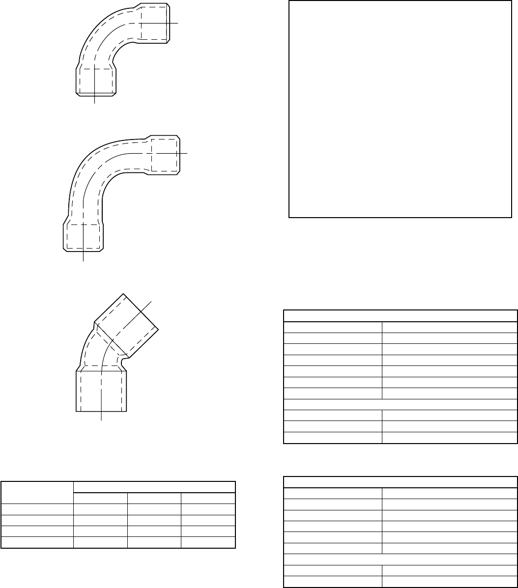
Fig. 3—Tube Bend Losses
TABLE 5—FITTING LOSSES IN EQUIVALENT FT
TUBE SIZE OD
(IN.) REFERENCE DIAGRAM IN FIG. 1
ABC
5/8 1.6 1.0 0.8
3/4 1.8 1.2 0.9
7/8 2.0 1.4 1.0
1-1/8 2.6 1.7 1.3
A92498
90° LONG RAD
B
90° STD
A
45° STD
C
TABLE 6—CALCULATION OF INDOOR PISTON NO.
OUTDOOR UNIT ABOVE INDOOR
FT PISTON CHANGE
0-25 0
26-50 -3
51-75 -5
76-100 -7
101-125 -9
126-150 -10
OUTDOOR UNIT BELOW INDOOR
FT PISTON CHANGE
0-25 0
26-50 +4
TABLE 7—CALCULATION OF OUTDOOR PISTON NO.
OUTDOOR UNIT ABOVE INDOOR
FT PISTON CHANGE
0-50 0
51-75 +4
76-100 +6
101-125 +8
126-150 +10
OUTDOOR UNIT BELOW INDOOR
FT PISTON CHANGE
0-50 0
—7—
NOTE: When installing a liquid-line solenoid, the system may
require a minimum 60va low-voltage transformer.
Each type of solenoid has an indicator flow arrow stamped on the
valve body. When solenoid is closed (not energized) and pressure
is applied in direction of flow arrow, complete shutoff occurs. If
pressure is applied against direction of flow arrow, leakage
through valve occurs. When determining proper installation of
valve within liquid line, 2 considerations must be made:
1. Direction of flow arrow
2. Where solenoid is installed in system.
TXVs can only be substituted for liquid-line solenoids in single-
flow air conditioning systems. Bi-flow TXVs allow liquid migra-
tion to coldest point during off cycles, which could allow liquid
into compressor.
Fig. 4 through 7 detail proper installation of liquid-line solenoid
and provide applications where TXVs may be substituted. Refer-
ence all notes of the appropriate figures.
V. CHARGING INFORMATION
Weigh in appropriate refrigerant charge, then use the standard
practices of superheat-charging method for piston applications and
subcooling-charging method for TXV applications to confirm
correct charge. The standard charging methods can be found on
outdoor unit-information plate, in unit Installation Instructions, or
in the Service Manual. Since total system charge is increased for
long-line applications, it may be necessary to calculate the
additional refrigerant charge. Since long-line applications only
involve 3/8-in. liquid lines, the additional refrigerant charge
required is 0.6 oz of Refrigerant 22 (R-22) per ft of 3/8-in. liquid
line over 15 ft.
EXAMPLE:
To calculate additional charge required for a 25–ft line set:
25 ft –15 ft = 10 ft X 0.6 oz/ft=6ozofadditional charge
The rating-plate charge of a given outdoor unit is for a standard
application of 15 ft of interconnecting tubing. The rating-plate
charge can be found on outdoor unit-rating plate or in outdoor
unit-presale literature. Long-line applications do not require addi-
tional oil charge.
VI. 2–SPEED APPLICATIONS
Outdoor units may be connected to indoor section using accessory
tubing package or field-supplied refrigerant grade tubing of correct
size and condition. In long–line applications, 2–speed units are
handled basically the same way as the single-speed units. There are
2 major differences:
1. For tubing up to 100 ft:
Liquid tube diameters and refrigerant connection diameters
for all sizes are 3/8 in.
Vapor tube diameter for the 036 and 048 is 7/8 in.; 060 is
1–1/8 in.
Vapor refrigerant connection diameter for all sizes is 7/8 in.
DO NOT INSTALL EQUIVALENT INTERCONNECT-
ING TUBING LENGTHS GREATER THAN 100 FT.
2. Do not increase or decrease tubing sizes.
For other applications see the previous sections under Long-Line
Guidelines.
UNIT IDENTIFICATION
I. PRODUCT NUMBER STAMPED ON UNIT-RATING
PLATE
The unit product number has 16 positions containing groups of
numbers and letters that indicate specific information about the
unit. Listed below is the breakdown of the 16 positions.
Positions 1, 2, and 3—Product Series
Example:
A 500–series number indicates a split-system condensing unit and
a 600–series number indicates a split-system heat pump.
Position 4—Model Letters
New models are introduced with the letter A, and subsequent
model changes are identified by changing to the next letter, as B,
then C, and so forth.
Position 5—Electrical Characteristics
Example:
J—208–230, 1 Phase, 60 Hertz
N—208/230, 208/240, 1 Phase, 60 Hertz
P—208/230, 208/240, 3 Phase, 60 Hertz
E—460, 3 Phase, 60 Hertz
Q—220, 3 Phase, 50 Hertz
S—220/240, 1 Phase, 50 Hertz
Z—380/415, 3 Phase, 50 Hertz
Position 6—Fuel and Controls
Not applicable on condensing units or heat pumps, so the letter ’X’
is used to signify ’none.’
Positions 7, 8, and 9—Nominal Cooling Capacity (in thousands
Btuh)
Example: 036 = 36,000 Btuh or 3–ton capacity.
Positions 10, 11, and 12—Not applicable on condensing units or
heat pumps, so the number ’zero’is used to signify ’none.’
Position 13—Brand Name
Example:
A—Common unit —U.S.A. Only
Position 14—Unit Series
New units are introduced with the letter A, and subsequent major
component variations, such as in compressor, fan motor, coil
circuitor size, etc., are identified by changing to the next letter, as
B, then C, and so forth.
TABLE 8—COMMON PISTON SIZES
CHECK-FLO-
RATER™CHATLEFF CHECK-FLO-
RATER™CHATLEFF
—32 65 65
—33 67 67
35 35 —68
—36 70 70
—37 —71
38 38 73 73
—39 —74
40 40 76 76
—41 78 78
42 42 80 80
—43 —81
—45 82 82
46 —84 84
—47 86 86
49 49 88 88
51 51 —89
52 52 90 90
—53 —92
55 55 93 93
57 57 96 96
59 59 98 98
61 61 101 101
—62 104 104
63 63 109 —
TABLE 9—LIQUID-LINE SOLENOID KIT PART NUMBERS
TYPE OF VALVE PART NO.
Single Flow KAALS0101LLS
Bi-Flow KHALS0401LLS
—8—
Positions 15 and 16—Product Variations
Example:
AA—Standard unit
Other letters—For product variations from standard
II. SERIAL NUMBER IDENTIFICATION
The unit serial number has 10 positions containing groups of
numbers and a letter that indicate specific information about the
unit. Listed below is the breakdown of the 10 positions.
Positions 1 and 2—Week of Manufacture
Example:
01—First week of a year
52—Last week of a year
Positions 3 and 4—Year of Manufacture
Example:
94—1994
Position 5—Manufacturing Site
Example:
A–Indianapolis
E–Collierville
Positions 6 through 10—Serial Number
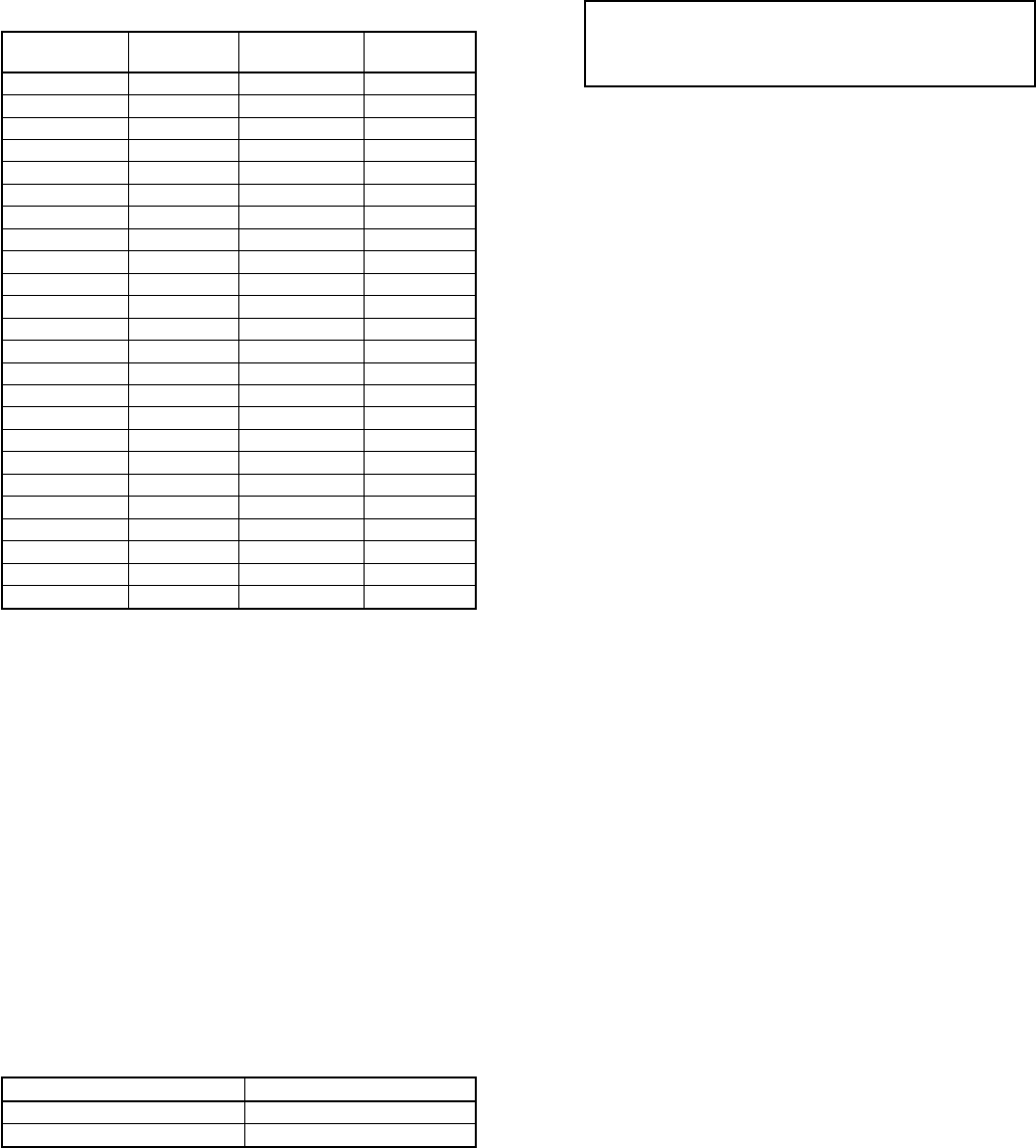
Fig. 4—Application with Air Conditioner Installed in a Horizontal Configuration
A90074
175' MAX.
GROUND LEVEL
BASEMENT
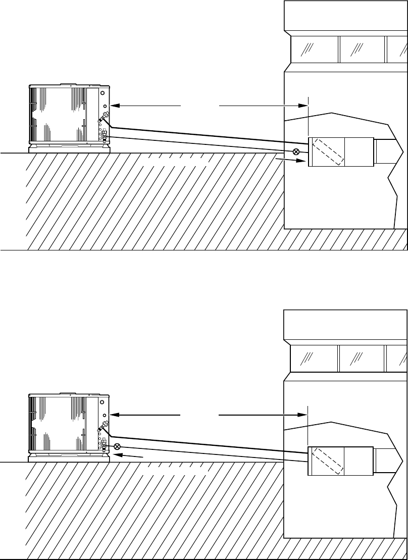
Fig. 5—Application with Heat Pump Installed in a Horizontal Configuration
A90075
175' MAX.
GROUND LEVEL
BASEMENT
—9—
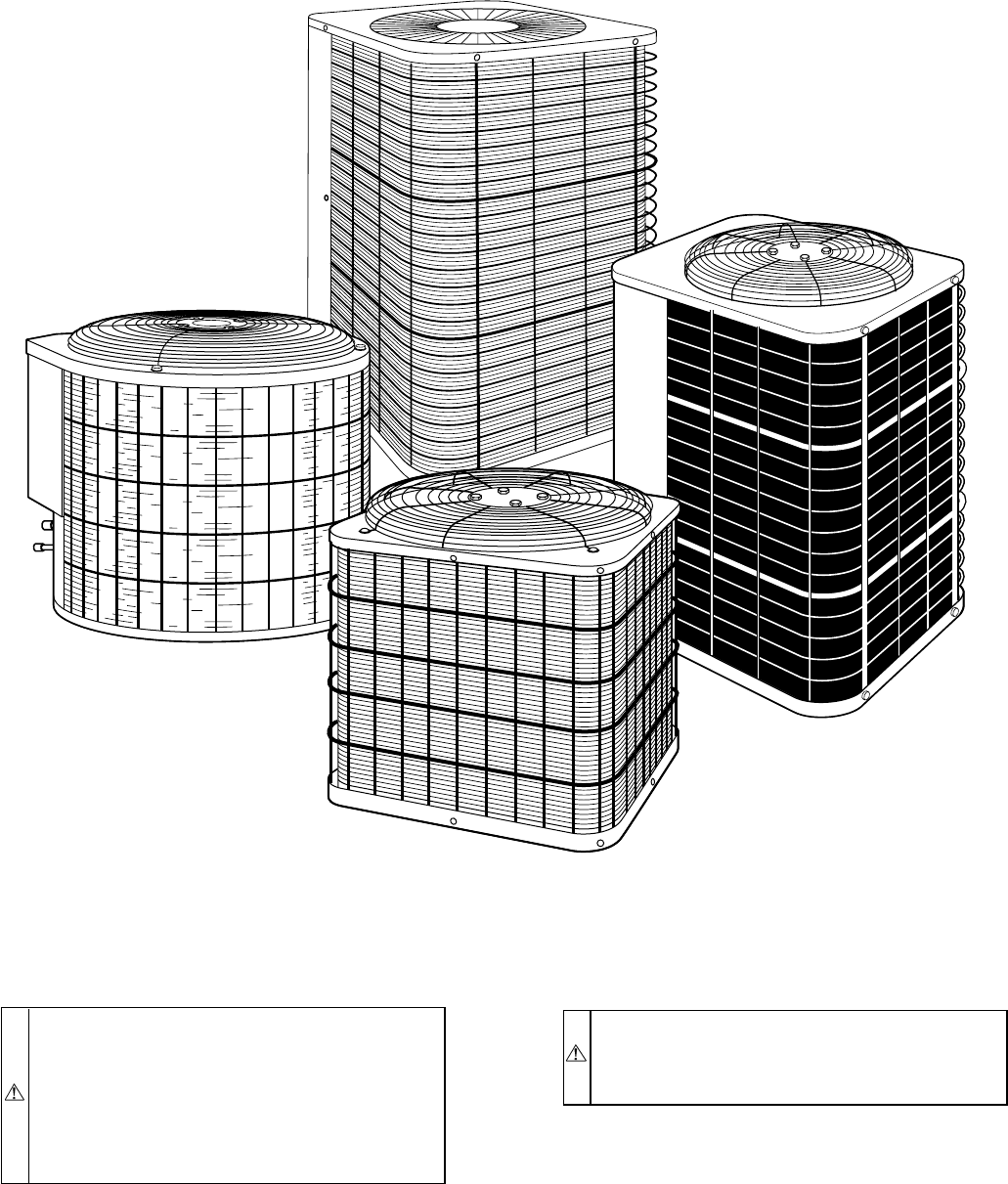
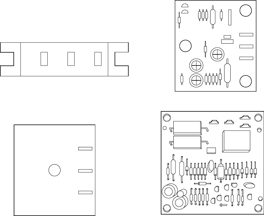
CABINET
Certain maintenance routines and repairs require removal of
cabinet panels. There are 4 basic cabinet designs for air condition-
ers and heat pumps. (See Fig. 8.) The horizontal discharge unit will
be discussed in a separate section of this manual. Note that
separate sections apply according to date of manufacture.
I. REMOVE TOP COVER—BEFORE 1/1/92
NOTE: This section applies to all Reliant products made prior to
January 1, 1992.
1. Turn off all power to outdoor and indoor units.
2. Remove screws holding top cover to coil grille and corner
posts.
3. Remove access panel.
4. Remove information plate.
5. Disconnect fan motor wires, cut wire ties, and remove wire
ties from control box. Refer to unit-wiring label.
6. Lift top cover from unit.
7. Reverse sequence for reassembly.
II. REMOVE FAN-MOTOR ASSEMBLY—BEFORE 1/1/92
NOTE: This section applies to all Reliant products made prior to
January 1, 1992.
1. Perform items 1 through 6 above.
2. Remove nuts holding fan-motor top cover.
3. Remove motor and fan blade assembly.
4. Reverse sequence for reassembly.
5. Prior to applying power, check that fan rotates freely.
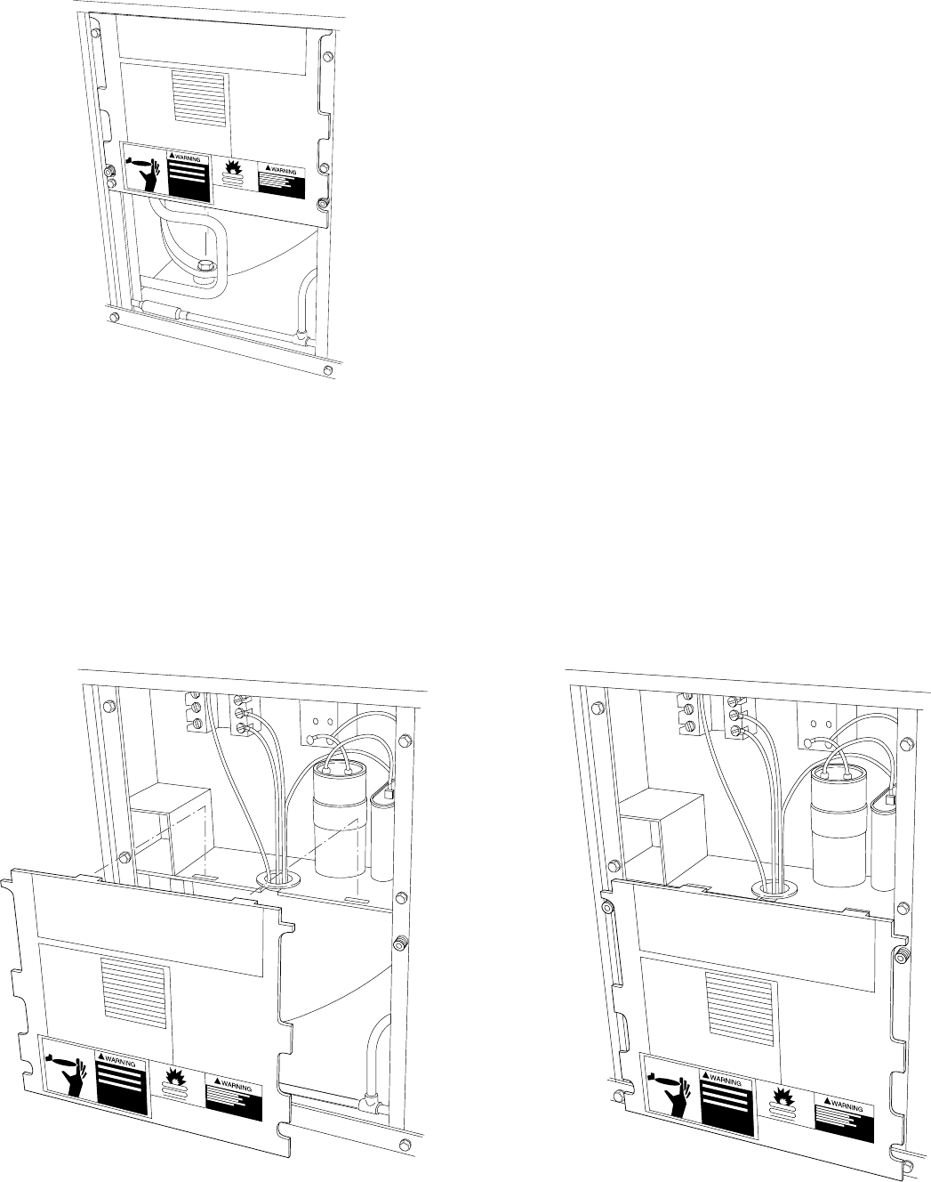
III. INFORMATION PLATE—RELIANT PRODUCTS
The information plate is secured to the front of the control box and
provides a cover for it. (See Fig. 9.) This plate also provides a
surface to attach the wiring schematic, superheat-charging tables
with instructions, and warning labels. The plate has 2 tabs on the
top edge that are bent down at slightly more than 90°. When the
information plate is removed, these tabs can be inserted into 2
mating slots in the bottom-front edge of the control box, and the
plate will hang down, forming a lower front panel. (See Fig. 10.)
This is convenient where access to the controls is required while
the unit is operating. The information plate on the small size casing
completely covers the opening below the control box. On larger
models, the information plate may not cover the entire opening. In
this instance, the top cover can be removed and placed on its side
to cover the additional space.
IV. CONTROL-BOX COVER—CUBE PRODUCTS
This panel contains much of the same information as the informa-
tion plate mentioned previously, but is designed only to cover the
control box.
V. REMOVE TOP COVER—AFTER 1/1/92
NOTE: The section applies to all Reliant Products made after
January 1, 1992.
1. Turn off all power to outdoor and indoor units.
2. Remove 5 screws holding top cover to coil grille and coil
tube sheet.
3. Remove 2 screws holding control-box cover.
4. Remove 2 screws holding information plate.
5. Disconnect fan motor wires, cut any wire ties, and move
wires out of control box and through tube clamp on back of
control box.
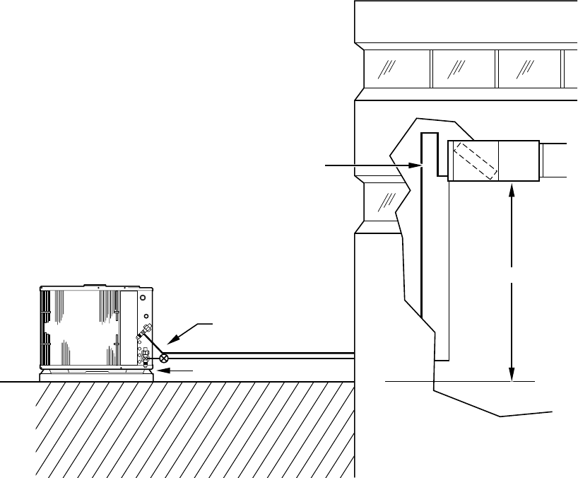
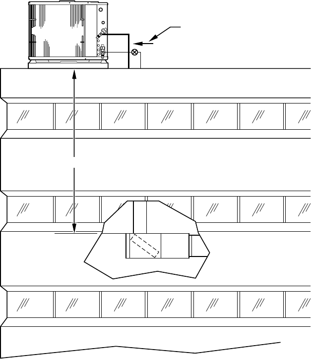
Fig. 6—Application with Air Conditioner or Heat Pump Installed with Indoor Unit Above Outdoor Unit
A90076
HEAT PUMP ONLY
50' MAX.
GROUND LEVEL
TRAP
—10—
6. Lift top cover from unit.
7. Reverse sequence for reassembly.
VI. REMOVE FAN-MOTOR ASSEMBLY—AFTER 1/1/92
NOTE: This section applies to all Reliant products made after
January 1, 1992
1. Perform items 1, 3, 4, and 5 above. (Note item 2 is not
required.)
2. Remove 4 screws holding wire basket to top cover.
3. Lift wire basket from unit.
4. Remove nuts holding fan motor to wire basket.
5. Remove motor and fan blade assembly.
6. Pull wires through wire raceway to change motor.
7. Reverse sequence for reassembly.
8. Prior to applying power, check that fan rotates freely.
Fig. 7—Application with Air Conditioner or Heat Pump Installed Above Indoor Unit
A90077
HEAT PUMP ONLY
150' MAX.
—11—
ELECTRICAL
WARNING: Exercise extreme caution when working on
any electrical components. Shut off all power to system
prior to troubleshooting. Some troubleshooting tech-
niques require power to remain on. In these instances,
exercise extreme caution to avoid danger of electrical
shock. ONLY TRAINED SERVICE PERSONNEL
SHOULD PERFORM ELECTRICAL TROUBLE-
SHOOTING.
Troubleshooting charts for air conditioning and heat pump units
are provided in the back of this manual. They enable the service
technician to use a systematic approach to locate the cause of a
problem and correct system malfunctions.
I. ALUMINUM WIRE
CAUTION: Aluminum wire may be used in the branch
circuit (such as the circuit between the main and unit
disconnect), but only copper wire may be used between
the unit disconnect and the unit on Bryant systems.
Whenever aluminum wire is used in the branch-circuit wiring with
this unit, adhere to the following recommendations.
Connections must be made in accordance with the National
Electrical Code (NEC), using connectors approved for aluminum
wire. The connectors must be UL-approved (marked Al/Cu with
the UL symbol) for the application and wire size. The wire size
selected must have a current capacity not less than that of the
copper wire specified and must not create a voltage drop between
the service panel and the unit in excess of 2 percent of the
unit-rated voltage.
To prepare the wire before installing the connector, all aluminum
wire must be ″brush scratched″and coated with a corrosion
inhibiter such as Pentrox A. When it is suspected that the
Fig. 8—Basic Cabinet Designs
A94003
—12—
connection will be exposed to moisture, it is very important to
cover the entire connection completely to prevent an electrochemi-
cal action that will cause the connection to fail very quickly. Do
not reduce the effective size of wire, such as cutting off strands so
that the wire will fit a connector. Proper size connectors should be
used. Check all factory and field electrical connections for
tightness. This should also be done after the unit has reached
operating temperatures, especially if aluminum conductors are
used.
II. CONTACTORS
NOTE: The section applies to single-speed models only.
The contactor provides a means of applying power to unit using
low voltage (24v) from transformer in order to power the contactor
coil. (See Fig. 11.) Depending on unit model, you may encounter
single-, double-, or triple-pole contactors to break power. One side
of the line may be electrically energized, so exercise extreme
caution when troubleshooting.
The contactor coil for residential air-conditioning units and heat
pumps is powered by 24vac. If contactor does not operate:
1. With power off, check whether contacts are free to move.
Check for severe burning or arcing on contact points.
2. With power off, use ohmmeter to check for continuity of
coil. Disconnect leads before checking. A low-resistance
reading is normal. Do not look for a specific value, as
different part numbers have different resistance values.
3. Reconnect leads and apply low-voltage power to contactor
coil. This may be done by leaving high-voltage power to
outdoor unit off, and turning thermostat to heat or cool.
Check voltage at coil with voltmeter. Reading should be
between 20v and 30v. Contactor should pull in if voltage is
correct and coil is good. If contactor does not pull in,
change contactor.
4. With high-voltage power off and contacts pulled in, check
for continuity across contacts with ohmmeter. A very low or
zero resistance should be read. Higher readings could
indicate burned or pitted contacts which may cause future
failures.
SEFL JOSDJ
SEFL JOSDJ
SEFL JOSDJ
SEFL JOSDJ
SEFL JOSDJ
SEFL JOSDJ
SEFL JOSDJ
SEFL JOSDJ PAASFLDLKREW
SEFL JOSDJ
SEFL JOSDJ ATC
SEFL JOSDJ
SEFL JOSDJ UTUHD
SEFL JOSDJ
SEFL JOSDJC MD
SEFL JOSDJ
SEFL JOSDJHR ITYALK
SEFL JOSDJ
SEFL JOSDJ
A88412
SEFL JOSDJ
SEFL JOSDJ
SEFL JOSDJ
SEFL JOSDJ
SEFL JOSDJ
SEFL JOSDJ
SEFL JOSDJ
SEFL JOSDJ PAASFLDLKREW
SEFL JOSDJ
SEFL JOSDJ ATC
SEFL JOSDJ
SEFL JOSDJ UTUHD
SEFL JOSDJ
SEFL JOSDJC MD
SEFL JOSDJ
SEFL JOSDJHR ITYALK
SEFL JOSDJ
SEFL JOSDJ
A88413
Fig. 10—Information Plate Removed/Installed Below Control Box
Fig. 9—Information Plate
A88411
SEFL JOSDJ
SEFL JOSDJ
SEFL JOSDJ
SEFL JOSDJ
SEFL JOSDJ
SEFL JOSDJ
SEFL JOSDJ
SEFL JOSDJ PAASFLDLKREW
SEFL JOSDJ
SEFL JOSDJ ATC
SEFL JOSDJ
SEFL JOSDJ UTUHD
SEFL JOSDJ
SEFL JOSDJC MD
SEFL JOSDJ
SEFL JOSDJHR ITYALK
SEFL JOSDJ
SEFL JOSDJ
—13—
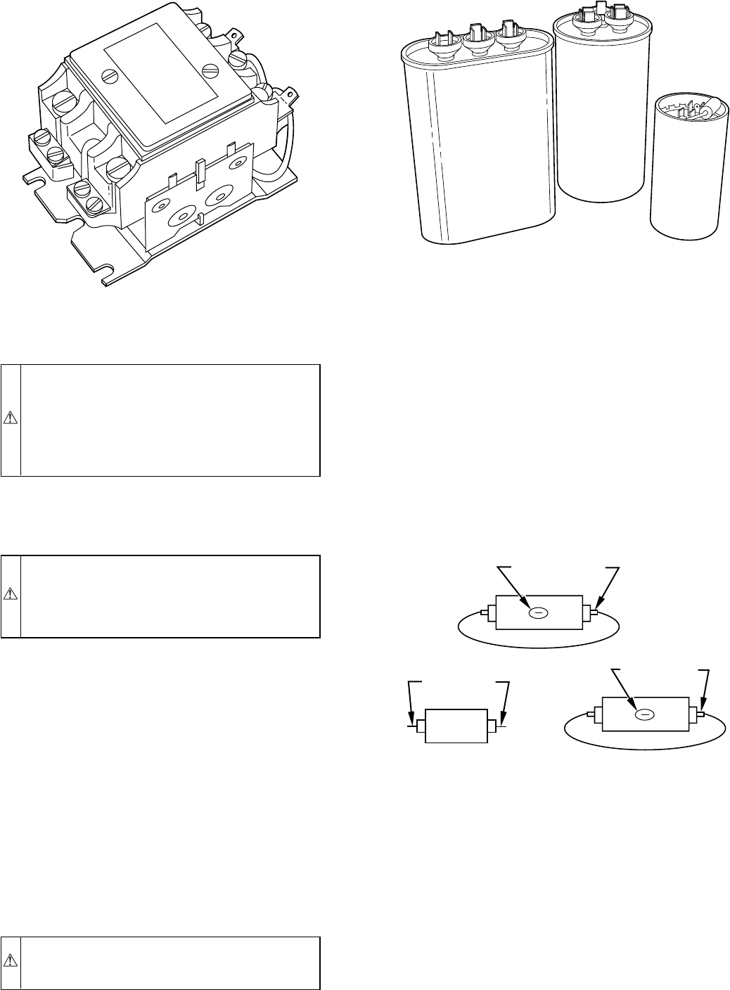
III. CAPACITORS
CAUTION: Capacitors can store electrical energy when
power is off. Electrical shock can result if you touch the
capacitor terminals and discharge the stored energy.
Exercise extreme caution when working near capacitors.
With power off, discharge stored energy by shorting
across the capacitor terminals with a 15,000-ohm, 2-watt
resistor.
NOTE: If bleed resistor is wired across start capacitor, it must be
disconnected to avoid erroneous readings when ohmmeter is
applied across capacitor. (See Fig. 12.)
CAUTION: Always check capacitors with power off.
Attempting to troubleshoot a capacitor with power on can
be dangerous. Defective capacitors may explode when
power is applied. Insulating fluid inside is combustible
and may ignite, causing burns.
Capacitors are used as a phase-shifting device to aid in starting
certain single-phase motors. Check capacitors as follows.
1. After power is off, discharge capacitors as outlined above.
Disconnect capacitor from circuit. Put ohmmeter on R X
10k scale. Using ohmmeter, check each terminal to ground
(use capacitor case). Discard any capacitor which measures
1/2–scale deflection or less. Place ohmmeter leads across
capacitor and place on R X 10k scale. Meter should jump to
a low-resistance value and slowly climb to higher value.
Failure of meter to do this indicates an open capacitor. If
resistance stays at zero or a low value, capacitor is inter-
nally shorted.
2. Capacitance testers are available which read value of
capacitor. If value is not within ± 10 percent value stated on
capacitor, it should be changed. If capacitor is not open or
shorted, the capacitance value is calculated by measuring
voltage across capacitor and current it draws.
WARNING: Exercise extreme caution when taking
readings while power is on. Electrical shock can cause
personal injury or death.
Use the following formula to calculate capacitance:
Capacitance (mfd) = (2650 X amps) divided by (volts)
3. Remove any capacitor that shows signs of bulging, dents, or
leaking. Do not apply power to a defective capacitor as it
may explode.
START CAPACITORS AND PTC DEVICES
Sometimes under adverse conditions, a standard run capacitor in a
system is inadequate to start compressor. In these instances, a
start-assist device is used to provide an extra starting boost to
compressor motor. The first device is called a positive-temperature
coefficient (PTC) or thermistor. (See Fig. 13.) It is a resistor wired
in parallel with the run capacitor. As current flows through the
PTC at start-up, it heats up. As it heats up, its resistance increases
greatly until it effectively lowers the current through it to an
extremely low value. This, in effect, removes it from the circuit.
After system shutdown, resistor cools and resistance value returns
to normal until next time system starts. If indoor coil does not have
a bleed-type expansion device, it may be necessary to remove start
thermistor and replace with accessory start capacitor and relay.
Consult pre-sale literature for application of start kits. Thermistor
device is adequate for most conditions; however, in systems where
off-cycle is short, device cannot cool fully and becomes less
effective as a start device. It is an easy device to troubleshoot.
1. Shut off all power to system.
2. Check thermistor with ohmmeter as described below.
3. Shut off all power to unit.
Fig. 11—Contactor
A88350 Fig. 12—Capacitors
A91455
Fig. 13—PTC Devices
A88414
20 OHM
(BLUE COLOR) 25 OHM
(BLUE COLOR)
12.5 OHM
(BEIGE COLOR)
12.5-22.5 OHMS
25-45 OHMS
20-36 OHMS
BLUE
—14—
4. Remove PTC from unit. Wait at least 10 minutes for PTC to
cool to ambient temperature.
5. Measure resistance of PTC with ohmmeter as shown in
Fig.13.
The cold resistance (RT) of any PTC device should be approxi-
mately 100 –180 percent of device ohm rating.
12.5–ohm PTC = 12.5–22.5 ohm resistance —beige color
25–ohm PTC = 25–45 ohm resistance —blue color
20–ohm PTC = 20–36 ohm resistance —blue color
If PTC resistance is appreciably less than rating or more than 200
percent higher than rating, device is defective.
If thermistor is good and compressor does not start:
1. Disconnect thermistor from starting circuit.
2. Give compressor a temporary capacitance boost (see next
section).
3. Run compressor for 10 minutes, shut off, and allow system
pressure to equalize.
4. Reconnect start thermistor.
5. Try restarting compressor without boost capacitor. If after 2
attempts compressor does not start, remove thermistor. Add
an accessory start-capacitor relay package.
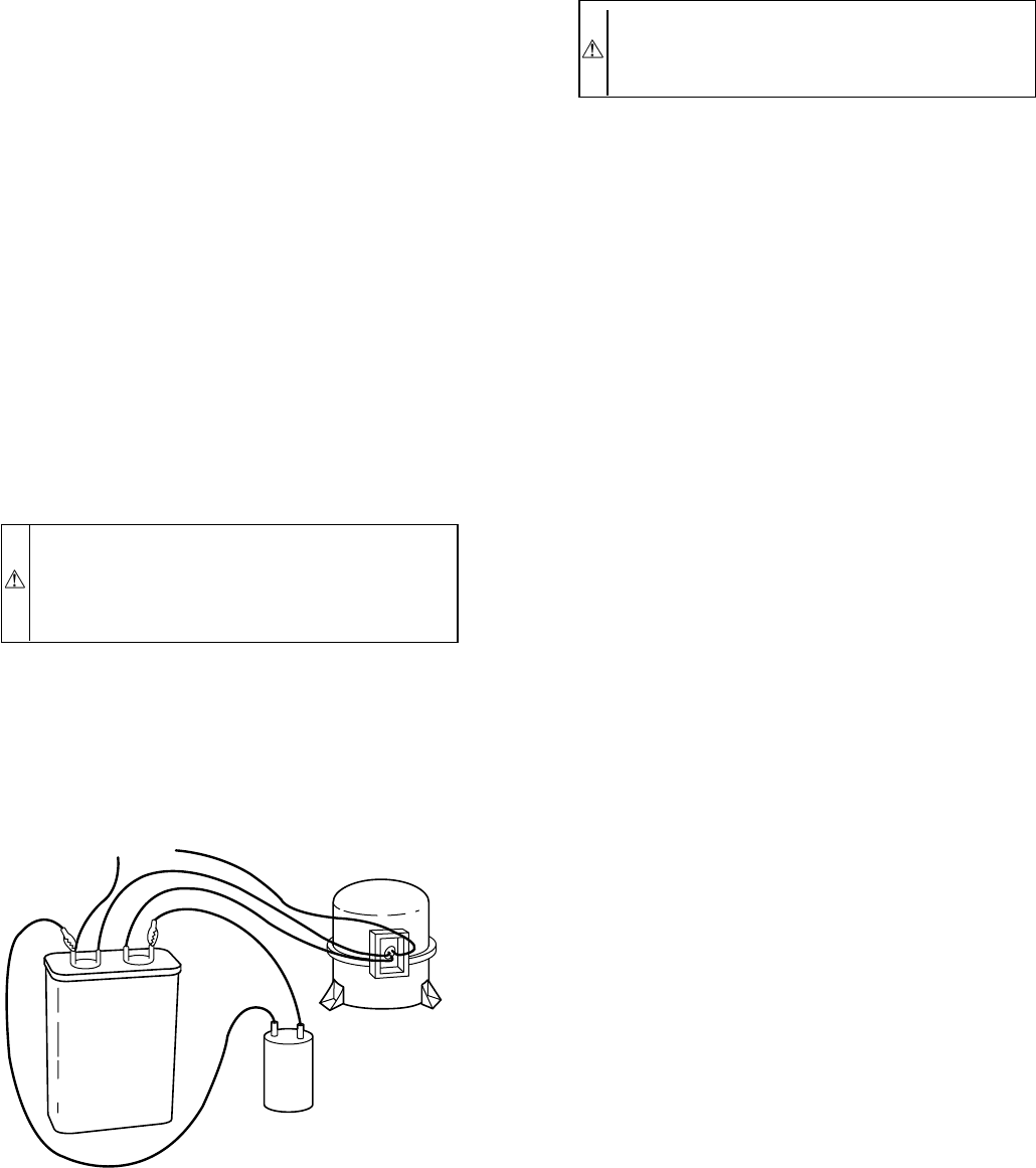
TEMPORARY CAPACITANCE BOOST
WARNING: Do not under any circumstances attach a
temporary boost capacitor directly to the compressor
terminals. Serious personal injury can result. Exercise
extreme caution with this procedure when high-voltage
power is on.
There are times when a temporary capacitance boost is needed to
get compressor started. (See Fig. 14.) If compressor motor does not
start, it may be due to low-line voltage, improper pressure
equalization, weak run capacitor, or a seized compressor. Check
each possibility and attempt capacitance boost before adding
auxiliary start capacitor and relay.
1. Turn off all power to unit. There may be more than one
power source to condensing unit.
NOTE: If a PTC is already installed, remove it from the system
by pulling PTC wires from H and C terminals on run capacitor.
2. Check compressor for ground or open windings. If wind-
ing’s resistance is within manufacturer’s recommendations,
proceed. (See Reciprocating Compressor Section II-
Electrical Failures for proper compressor-winding check.)
CAUTION: Do not check winding at compressor termi-
nals with pressure in the system. Check resistance by
removing wires attached at the compressor contactor and
run capacitor.
3. Obtain a start capacitor in the range of
150–180µF[@0330] volts rating. Connect 8–gauge wires
with insulated clips or terminals to the H and C terminals of
the run capacitor.
4. Turn power on to unit. If compressor starts, immediately
remove start-capacitor wires from H and C terminals of run
capacitor, using a pair of insulated, needle-nose pliers. DO
NOT leave start capacitor attached to run capacitor for more
than 3 seconds, even if compressor doesn’t start.
5. Discharge start capacitor by using a pair of insulated,
needle-nose pliers and shorting a 15,000 ohm, 2 watt
resistor across terminals.
NOTE: Some start capacitors already have a bleed resistor
attached. If so, it will discharge itself over a short period of time.
6. Run compressor 10 minutes. Stop and allow unit to sit idle
for 5 minutes.
7. Check system pressure equalization.
8. Attempt to restart without capacitance boost.
If PTC thermistor device is inadequate as start device, a start
capacitor and relay may be added to system to ensure positive start.
Capacitor is wired in parallel with run capacitor through normally
closed set of contacts on a device called start relay. The relay coil
is wired across start and common terminals of compressor. The
added capacitance gets the compressor started. As compressor
comes up to speed, voltage across start and common terminals
increases to a value high enough to cause start relay to energize.
This opens normally closed contacts and removes start capacitor
from circuit. In actual practice, this occurs in a fraction of a
second.
NOTE: If bleed resistor is wired across start capacitor, it must be
disconnected to avoid erroneous readings when ohmmeter is
applied across capacitor.
To check start relay and capacitor:
1. Turn off all power to unit.
2. Discharge start and run capacitors as outlined earlier.
3. Most start capacitors will have a 15,000 ohm, 2 watt bleed
resistor. Disconnect these devices from system.
Start capacitor can be inspected visually. It is designed for short
duration or intermittent duty. If left in circuit for prolonged period,
start capacitor blows through a specially designed bleed hole. If it
appears blown, check for welded contacts in start relay. Start
capacitor can be checked by ohmmeter method discussed earlier.
Start relay is checked with ohmmeter. Check for continuity across
coil of relay. You should encounter a high resistance. Since relay
contacts are normally closed, you should read low resistance
across them. Both PTC device and capacitor-relay start system are
standard equipment on some of these units. They are also available
as accessories and may be field-installed.
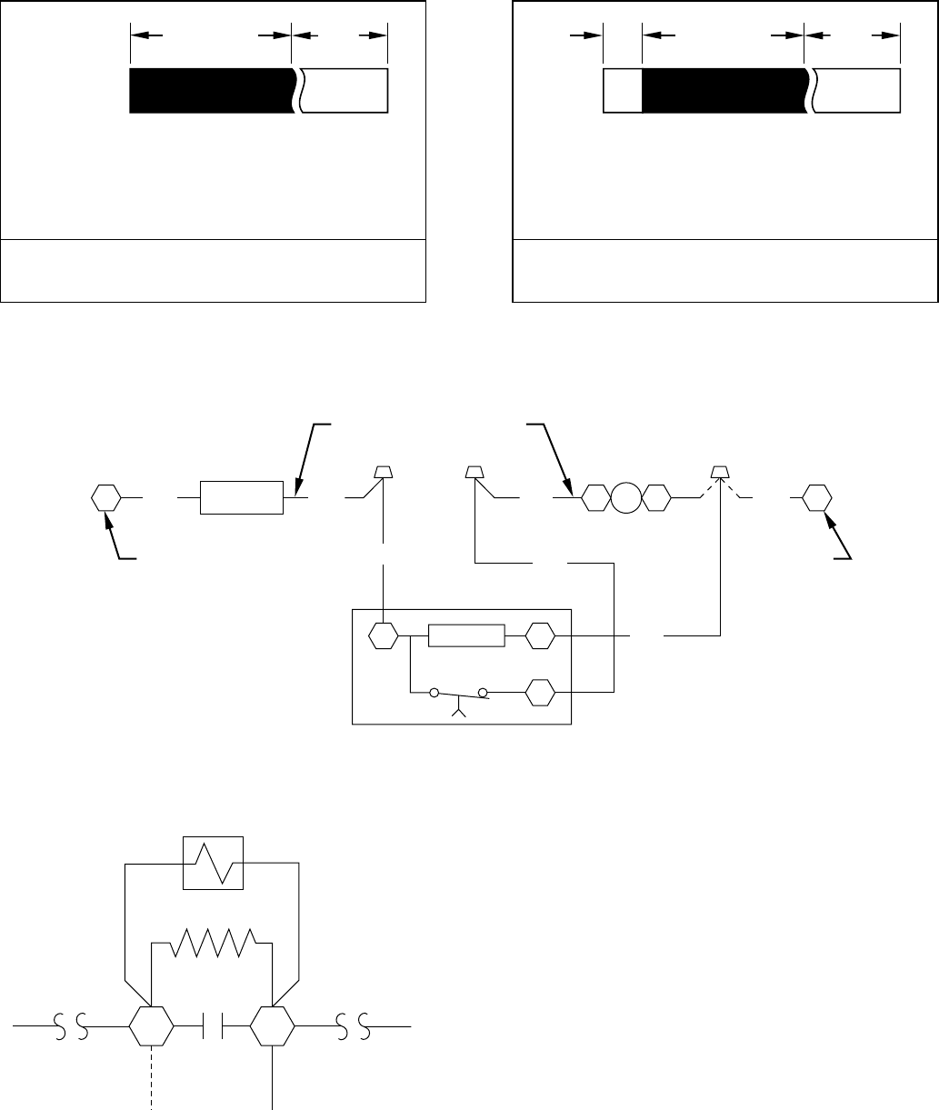
IV. CYCLE PROTECTOR
Solid-state cycle-protector device protects unit compressor by
preventing short cycling. After a system shutdown, cycle protector
provides fora5±2-minute delay before compressor restarts. On
normal start-up, a 5-minute delay occurs before thermostat closes.
After thermostat closes, cycle protector device provides a 3-sec
delay on HN67PA025, HN67ZA003, and HN67ZA008. (See Fig.
15, 16, and 17.)
Fig. 14—Capacitance Boosting
A88349
START (BOOST)
CAPACITOR
COMP. RUN
CAPACITOR
220-V FROM UNIT
CONTACTOR
—15—
Cycle-protector device is simple to troubleshoot. Only a voltmeter
capable of reading 24v is needed. Device is in control circuit;
therefore, troubleshooting is safe with control power (24v) on and
high-voltage power off.
With high-voltage power off, attach voltmeter leads across T1 and
T3 and set thermostat so that Y terminal is energized. Make sure
all protective devices in series with Y terminal are closed.
Voltmeter should read 24v across T1 and T3. With 24v still
applied, move voltmeter lead from T1 terminal to T2 terminal
across T2 and T3. After5±2minutes, voltmeter should read 24v,
indicating control is functioning normally. If no time delay is
encountered or device never times out, change control.
V. CRANKCASE HEATER
Crankcase heater is a device for keeping compressor oil warm. By
keeping oil warm, refrigerant does not migrate to and condense in
compressor shell when the compressor is off. This prevents
flooded starts which can damage compressor.
Crankcase heaters come in 2 basic types: wraparound-(bellyband)
type that is wrapped externally around compressor shell, and
insertion-type that is inserted into compressor oil well in shell of
compressor. Both types are used in outdoor units.
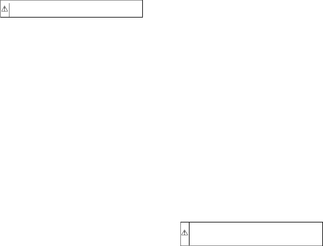
On units that have a single-pole contactor, the crankcase heater is
wired parallel with the contactor contacts and in series with the
compressor. (See Fig. 18.) When the contacts are open, a circuit is
completed from the line side of the contactor, through the
crankcase heater, through the run windings of the compressor, and
to the other side of the line. When the contacts are closed, there is
no circuit through the crankcase heater because both leads are
connected to the same side of the line. This allows the heater to
operate when the system is not calling for heating/cooling. The
heater does not operate when the system is calling for
heating/cooling. On units with 2 or 3 pole contactors, the crank-
case heater is connected to the line side of the contactor and is not
controlled by the contactor contacts.
The crankcase heater is powered by high-voltage power of unit.
Use extreme caution troubleshooting this device with power on.
The easiest method of troubleshooting is to apply voltmeter across
crankcase heater leads to see if heater has power. Do not touch
heater. Carefully feel area around crankcase heater. If warm,
crankcase heater is probably functioning. Do not rely on this
method as absolute evidence heater is functioning. If compressor
has been running, the area will still be warm.
With power off and heater leads disconnected, check across leads
with ohmmeter. Do not look for a specific resistance reading.
Check for resistance or an open circuit. Change heater if an open
circuit is detected. Some crankcase heaters in this series of units
are equipped with a crankcase-heater switch. This energy-saving
device shuts off power to heater when temperatures are high
enough that heater is not needed. Be sure this switch is functioning
normally before condemning crankcase heater.
VI. TIME-DELAY RELAY
The time-delay relay (TDR) is a solid-state-controlled, recycle-
delay timer which keeps the indoor blower operating for 90 sec
after thermostat is satisfied. This delay enables the blower to
remove residual cooling in the coil after compression shutdown,
T3 T1 T2
HN67ZA002
A91438
A91439
T3
T1
HN67ZA003
T2
T3
T1
HN67ZA008
T2
A94005
T1 YEL T2 VIO T3 BLK
T3 BLK
HN67PA025
A91440
Fig. 15—Cycle-Protector Device
—16—
thereby improving the efficiency of the system. The sequence of
operation is that on closure of the wall thermostat and at the end of
a fixed on-delay of 1 sec, the fan relay is energized. When the
thermostat is satisfied, an off-delay is initiated. When the fixed
delay of 90 ± 20 sec is completed, the fan relay is de-energized and
fan motor stops. If the wall thermostat closes during this delay, the
TDR is reset, and the fan relay remains energized. The TDR is a
24v device that operates within a range of 15 to 30v and draws
about 0.5 amps.
If the blower runs continuously instead of cycling off when the fan
switch is set on AUTO, the TDR is probably defective and must be
replaced.
VII. PRESSURE SWITCHES
Pressure switches are protective devices wired into control circuit
(low voltage). They shut off compressor if abnormally high or low
pressures are present in the refrigeration circuit. Depending on unit
model, you may find a low- and/or high-pressure switch in system.
LOW-PRESSURE SWITCH
Located on suction line of condensing unit only, the low-pressure
switch protects against low-suction pressures caused by such
events as loss of charge, low airflow across indoor coil, dirty
filters, etc. It opens on a pressure drop at about 27 psi. If system
pressure is above this, switch should be closed. To check switch,
turn off all power to unit, disconnect leads on switch, and apply
ohmmeter leads across switch. You should have continuity on a
good switch. Because these switches are attached to refrigeration
system under pressure, it is not advisable to remove this device for
troubleshooting unless you are reasonably certain that a problem
exists. If switch must be removed, remove and recover all system
charge so that pressure gages read 0 psi.
OPERATING
TIME 5 MIN
T1
_
T2
BLK DENOTES CLOSED CONTACTS
HN67ZA002 A91436
Fig. 16—Cycle-Protector Sequence
3
SEC OPERATING
TIME 5 MIN
T1
_
T2
BLK DENOTES CLOSED CONTACTS
HN67PA025, HN67ZA003, HN67ZA008
A91437
Fig. 17—Cycle-Protector Wiring
A88415
T1 T3
T2
LOGIC
YEL C BRNYEL
SAFETY
CONTROL
YEL
CUT YELLOW WIRE
BETWEEN CONTACTOR AND
LOW-PRESSURE SWITCH
TERMINAL
BOARD
CONNECTION
TERMINAL
BOARD
CONNECTION
CY
VIO
YEL
BLK
Fig. 18—Wiring for Single-Pole Contactor
A91426
CH
DSV
2111
—17—
CAUTION: Wear safety glasses and gloves when work-
ing with refrigerants.
Apply heat with torch to solder joint and remove switch. Wear
safety glasses when using torch. Have quenching cloth available.
Oil vapor in line may ignite when switch is removed. Braze in
1/4-in. flare fitting and screw on replacement pressure switch.
HIGH-PRESSURE SWITCH
Located on discharge line, the high-pressure switch protects
against high-discharge pressures caused by such events as over-
charge, condenser-fan motor failure, system restriction, etc. It
opens on pressure rise at about 435 psi. If system pressures go
above this setting during abnormal conditions, the switch opens.
Do not attempt to simulate these system abnormalities as high
pressures pose a serious safety hazard. High-pressure switch is also
checked with an ohmmeter similar to checking low-pressure
switch. If system pressure is below 435 psi, the switch shows
continuity. It is replaced in the same manner as low-pressure
switch. Observe all safety precautions.
LIQUID-LINE PRESSURE SWITCH
Located on liquid line of heat pump only, the liquid-line pressure
switch functions similar to conventional low-pressure switch.
Because heat pumps experience very low suction pressures during
normal system operation, a conventional low-pressure switch
cannot be installed on suction line. This switch is installed in liquid
line instead and acts as loss-of-charge protector. The liquid line is
the low side of the system in heating mode. It operates identically
to low-pressure switch except it opens at 7 psi when the heating
piston is in the liquid valve or 27 psi when the heating piston is in
the liquid line. Troubleshooting and removing this switch is
identical to procedures used on other switches. Observe same
safety precautions.
VIII. DEFROST THERMOSTATS
Defrost thermostat signals heat pump that conditions are right for
defrost or that conditions have changed to terminate defrost. It is
a thermally actuated switch clamped to outdoor coil to sense its
temperature. Normal temperature range is closed at 30°±3°F and
open at 80°±5°F.
NOTE: The defrost thermostat must be located on the liquid side
of the outdoor coil on the bottom circuit and as close to the coil as
possible.
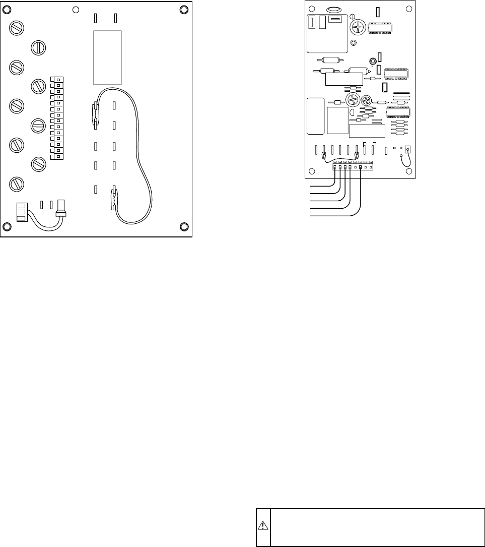
IX. DEFROST-CONTROL BOARD
Solid-state defrost boards used on heat pumps replace electrome-
chanical timer and defrost relay found on older defrost systems.
The defrost-control board can be field-set to check need for defrost
every 30, 50, or 90 minutes of operating time by connecting the
jumper (labeled W1 on the circuit board) to the terminal for the
defrost time desired. The board is set at factory for 90 minutes. The
defrost period is field-selectable, depending upon geographic areas
and defrost demands. Two types of defrost boards are used, and
functions are described in the sections to follow.
Troubleshooting defrost control involves a series of simple steps
that indicate whether or not board is defective.
NOTE: This procedure allows the service technician to check
control board and defrost thermostat for defects. First troubleshoot
to make sure unit operates properly in heating and cooling modes.
This ensures operational problems are not attributed to the defrost-
control board.
HK32FA003, 006 DEFROST CONTROL
This control board utilizes screw terminals for the low-voltage
field wiring. The board has a feature that allows the heat pump to
restart in defrost if room thermostat is satisfied during defrost. To
troubleshoot the board, perform the following items.
1. Turn thermostat to OFF. Shut off all power to outdoor unit.
2. Remove control-box cover for access to electrical compo-
nents and defrost-control board.
3. Disconnect defrost-thermostat leads from control board and
connect to ohmmeter. Thermostat leads are the black,
insulated wires connected to DFT and R terminals on
control board. Resistance reading may be zero (indicating
closed defrost thermostat) or infinity (∞for open thermo-
stat) depending on outdoor temperature.
4. Jumper between DFT and R terminals on control board as
shown in Fig. 19.
5. Disconnect outdoor fan motor lead from OF2. Tape lead to
prevent grounding.
6. Turn on power to outdoor unit.
7. Restart unit in heating, allowing frost to accumulate on
outdoor coil.
8. After a few minutes in heating, liquid-line temperature at
defrost thermostat should drop below closing set point of
defrost thermostat of approximately 30°F. Using ohmmeter,
check resistance across defrost-thermostat leads. Resistance
of zero indicates defrost thermostat is closed and operating
properly.
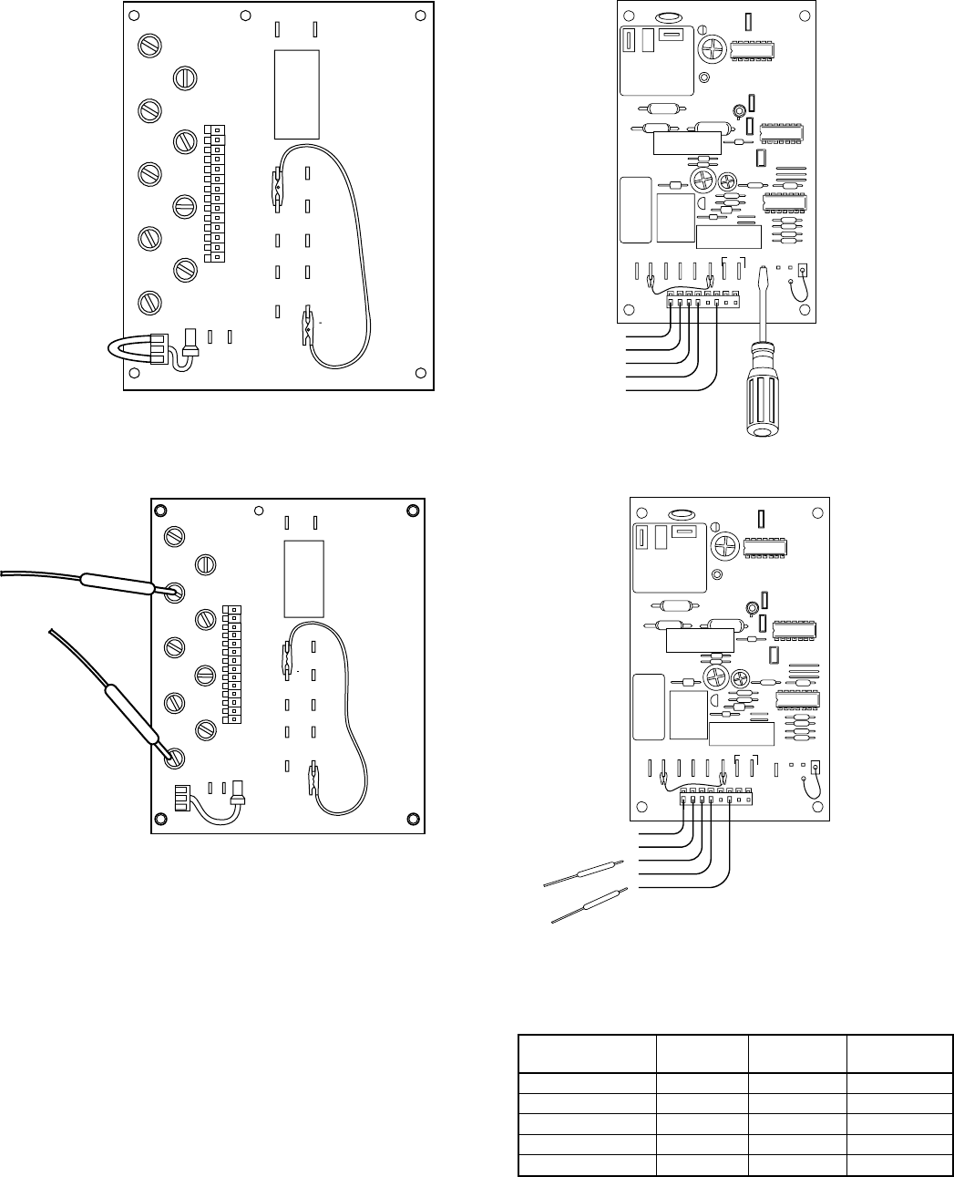
9. Remove protective cover from TP1 and TP2 speed-up
terminals. Install jumper wire on speed-up terminals. This
reduces the timing sequence to 1/60 of original time. (See
Fig. 20.) Since Fig. 20 shows timing cycle set at 30 minutes,
unit initiates defrost within approximately 30 sec; if setting
is at 50 minutes, within 50 sec; 90 minutes, within 90 sec.
When you hear the reversing valve change position, remove
protective cover/jumper. Otherwise, control will terminate
normal 10-minute defrost cycle in approximately 10 sec.
CAUTION: Exercise extreme caution when shorting
speed-up pins. If pins are accidentally grounded, damage
to the control board will occur.
10. Unit is now operating in defrost mode. Using voltmeter,
check between C and W2 as shown in Fig. 21. Reading on
voltmeter should indicate 24v. This step ensures defrost
relay contacts have closed, energizing supplemental heat
(W2) and reversing valve solenoid (O).
11. Unit should remain in defrost no longer than 10 minutes.
Actual time in defrost depends on how quickly speed-up
jumper is removed. If it takes 3 sec to remove speed-up
jumper after unit has switched to defrost, only 7 minutes of
defrost cycle remains.
12. After a few minutes in defrost (cooling) operation, liquid
line should be warm enough to have caused defrost-
thermostat contacts to open. Check resistance across defrost
thermostat. Ohmmeter should read infinite resistance, indi-
cating defrost thermostat has opened at approximately 80°F.
13. Shut off unit power and reconnect fan lead.
14. Remove jumper wire from speed-up terminal and reinsert
cover on speed-up terminals. Failure to remove jumper
causes unit to speed up operating cycles continuously.
15. Remove jumper between DFT and R terminals. Reconnect
defrost thermostat leads.
16. Replace control-box cover. Restore power to unit.
If defrost thermostat does not check out following above items or
incorrect calibration is suspected, check for a defective thermostat
as follows.
1. Follow items 1-5 above.
—18—
2. Using thermocouple temperature-measuring device, route
sensor or probe underneath coil (or other convenient loca-
tion). Attach to liquid line near defrost thermostat. Insulate
for more accurate reading.
3. Turn on power to outdoor unit.
4. Restart unit in heating mode.
5. Within a few minutes, liquid-line temperature drops within
a range causing defrost thermostat contacts to close. Tem-
perature range is from 33°Fto27°F. Notice temperature at
which ohmmeter reading goes from ∞to zero ohms.
Thermostat contacts close at this point.
6. Remove protective cover from TP1 and TP2 speed-up
terminals, and install jumper wire on the speed-up termi-
nals.
7. Unit changes over to defrost within 90 sec (depending on
timing cycle setting). Liquid-line temperature rises to range
where defrost thermostat contacts open. Temperature range
is from 75°Fto85°F. Resistance goes from zero to ∞when
contacts open.
8. If either opening or closing temperature does not fall within
above ranges or thermostat sticks in 1 position, replace
thermostat to ensure proper defrost operation.
CES0110063 DEFROST CONTROL
Some heat pumps built in 1991 and later incorporate a new defrost
control. The screw terminals found on the previous control board
have been replaced by a connector plug with stripped-wire leads.
This control board also contains the feature that allows the heat
pump to restart in defrost if the room thermostat is satisfied during
defrost. The board also contains a 5-minute cycle protector that
prevents the unit from short cycling after it cycles off or after a
power interruption. To troubleshoot the board, perform the follow-
ing items.
1. Turn thermostat to OFF. Shut off all power to outdoor unit.
2. Remove control-box cover for access to electrical compo-
nents and defrost-control board.
3. Disconnect defrost-thermostat leads from control board,
and connect to ohmmeter. Thermostat leads are the black,
insulated wires connected to DFT and R terminals on
control board. Resistance reading may be zero (indicating
closed-defrost thermostat), or infinity (∞for open thermo-
stat) depending on outdoor temperature.
4. Jumper between DFT and R terminals on control board as
shown in Fig. 21.
5. Disconnect outdoor fan-motor lead from OF2. Tape lead to
prevent grounding.
6. Turn on power to outdoor unit.
7. Restart unit in heating mode, allowing frost to accumulate
on outdoor coil.
8. After a few minutes in heating mode, liquid-line tempera-
ture at defrost thermostat should drop below closing set
point of defrost thermostat of approximately 30°F. Check
resistance across defrost thermostat leads using ohmmeter.
Resistance of zero indicates defrost thermostat is closed and
operating properly.
9. Short between the speed-up terminals using a thermostat
screwdriver. This reduces the timing sequence to 1/256 of
original time. (See Fig. 20 and Table 10.)
NOTE: Fig. 20 shows timing cycle set at 30 minutes; however,
for the CES30110063 board the timing cycle will be set for 90 min
and unit initiates defrost within approximately 21 sec. When you
hear the reversing valve change position, remove screwdriver
immediately. Otherwise, control will terminate normal 10-minute
defrost cycle in approximately 2 sec.
CAUTION: Exercise extreme caution when shorting
speed-up pins. If pins are accidentally shorted to other
terminals, damage to the control board will occur.
10. Unit is now operating in defrost mode. Check between C
and W2 using voltmeter as shown in Fig. 21. Reading on
voltmeter should indicate 24v. This step ensures defrost-
relay contacts have closed, energizing supplemental heat
(W2) and reversing valve solenoid (O).
11. Unit should remain in defrost no longer than 10 minutes.
Actual time in defrost depends on how quickly speed-up
jumper is removed. If it takes 2 sec. to remove speed-up
jumper after unit has switched to defrost, the unit will
switch back to heat mode.
12. After a few minutes in defrost (cooling) operation, liquid
line should be warm enough to have caused defrost-
thermostat contacts to open. Check resistance across defrost
thermostat. Ohmmeter should read infinite resistance, indi-
cating defrost thermostat has opened at approximately 80°F.
G
E
W2 14
L
W3
R
Y
O
C
W1
30 50
OF2 OF1
GC
C
C
R
R
C
Y
ODFT
HK32FA003/HK32FA006
A88402
OF1
OF2
ORT2 Y TI DFT CTEST 30 50 90
W1
O
R
W2
Y
C
CES0110063,
CES0130024 A91442
Fig. 19—Jumper DFT and R Terminals
—19—
13. Shut off unit power and reconnect fan lead.
14. Remove jumper between DFT and R terminals. Reconnect
defrost-thermostat leads. Failure to remove jumper causes
unit to switch to defrost every 30, 50, or 90 minutes and
remain in defrost for full 10 minutes.
15. Replace control-box cover. Restore power to unit.
If defrost thermostat does not check out following above items or
incorrect calibration is suspected, check for a defective thermostat
as follows.
1. Follow items 1-5 above.
2. Route sensor or probe underneath coil (or other convenient
location) using thermocouple temperature-measuring de-
vice. Attach to liquid line near defrost thermostat. Insulate
for more accurate reading.
3. Turn on power to outdoor unit.
4. Restart unit in heating.
5. Within a few minutes, liquid-line temperature drops within
a range causing defrost-thermostat contacts to close. Tem-
perature range is from 33°Fto27°F. Notice temperature at
which ohmmeter reading goes from ∞to zero ohms.
Thermostat contacts close at this point.
G
E
W2
14
L
W3
R
Y
O
C
W1
90
50
OF2
OF1
GC
C
C
R
R
C
Y
ODFT
HK32FA003/HK32FA006
A88404
OF1
OF2
ORT2 Y TI DFT CTEST 30 50 90
W1
O
R
W2
Y
C
CES0110063,
CES0130024
A91444
Fig. 20—Inserting Jumper Wire
G
E
W2 14
L
W3
R
Y
O
C
W1
30 50
OF2 OF1
GC
C
C
R
R
C
Y
ODFT
HK32FA003/HK32FA006
A88403
OF1
OF2
ORT2 Y TI DFT CTEST 30 50 90
W1
O
R
W2
Y
C
CES0110063,
CES0130024
A91443
Fig. 21—Checking Between C and W2
TABLE 10—DEFROST CONTROL SPEED-UP TIMING SE-
QUENCE FOR CES0110063/CES0130024
PARAMETER MINIMUM MAXIMUM SPEED-UP
(NOMINAL)
30-minute cycle 27 33 7 sec
50-minute cycle 45 55 12 sec
90-minute cycle 81 99 21 sec
10-minute cycle 9 11 2 sec
5 minutes 4.5 5.5 1 sec
—20—
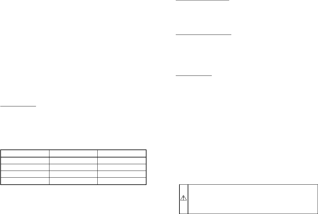
6. Short between the speed-up terminals using a small, slotted
screwdriver.
7. Unit changes over to defrost within 21 sec (depending on
timing-cycle setting). Liquid-line temperature rises to range
where defrost-thermostat contacts open. Temperature range
is from 75°Fto85°F. Resistance goes from zero to ∞when
contacts open.
8. If either opening or closing temperature does not fall within
above ranges or thermostat sticks in 1 position, replace
thermostat to ensure proper defrost operation.
CES0130024 DEFROST CONTROL
Some heat pumps built in 1993 and later incorporated a new
defrost control similar to the CES0110063 except the 5-minute
cycle protector has been removed. This control is used on heat
pump units with reciprocating compressors where short-cycle
protection is not required.
Troubleshooting this control will be the same as the CES0110063
control except for the cycle-protector function. The CES0130024
control is identical to the CES0110063 except the T2 terminal and
cycle-protector logic have been removed.
CES0130076 DEFROST CONTROL
This defrost control is the same size as the CES0130063 control
but is not backwards-compatible. (See Fig. 22.) To upgrade to the
new control, you must have replacement-defrost thermostat and
harness kit. See your replacement-component representative for kit
part number.
Defrost Settings
The defrost control is a time/temperature control which includes a
field-selectable time period (DIP switch 1 and 2 on board, see
Table 11) between defrost cycles of 30, 60, 90, and 120 minutes
(factory-set at 90 minutes).
To initiate a forced defrost, two options are available, depending
on the status of the defrost thermostat.
If defrost thermostat is closed, speedup pins (J1) must be shorted
by placing a Flathead screwdriver in between for 5 seconds and
releasing, to observe a complete defrost cycle. When the Quiet
Shift switch is selected, compressor will be turned off for two,
30–second intervals during this complete defrost cycle. When
Quiet Shift switch is in factory-default OFF position, a normal and
complete defrost cycle will be observed.
If defrost thermostat is in open position and speedup pins are
shorted (with a Flathead screwdriver) for 5 seconds and released,
a short defrost cycle will be observed (actual length is dependent
upon the selected Quiet Shift position). When Quiet Shift switch is
in ON position, the length of defrost is 1 minute (30 seconds
compressor-off period followed by 30 seconds of defrost with
compressor operation). On return to heat operation, compressor
will again turn off for an additional 30 seconds and the fan for 40
seconds. When the Quiet Shift is in OFF position, only a brief
30–second cycle will be observed.
If it is desirable to observe a complete defrost in warmer weather,
the thermostat must be closed as follows.
1. Turn off power to outdoor unit.
2. Disconnect outdoor fan-motor lead from OF2 on control
board. (See Fig. 22.) Tape to prevent grounding.
3. Restart unit in heating mode, allowing frost to accumulate
on outdoor coil.
4. After a few minutes in heating mode, liquid-line tempera-
ture should drop below closing point of defrost thermostat
(approximately 30°F.
NOTE: Unit will remain in defrost until defrost thermostat
reopens at approximately 80°F coil temperature at liquid line or
remainder of defrost cycle time.
5. Turn off power to outdoor unit and reconnect fan-motor
lead to OF2 on control board after above forced-defrost
cycle.
Compressor Shut Down
This control has the option of shutting down the compressor for 30
seconds while going into and out of defrost modes. This is
accomplished by turning DIP switch 3 to the ON position. See Fig.
22 for switch position. Factory default is in the OFF position.
Five-Minute Time Delay
This control has a 5–minute time delay on startup. The speedup
terminals can be used to bypass this delay. Momentary shorting
across the speedup terminals will, upon release, bypass 5–minute
time delay. Do not short out the speedup terminals for more than
5 seconds, or defrost mode will be initiated.
Troubleshooting
Troubleshooting this control is done in the same manner as the
CES0130063 control with the exceptions listed above.
DEFROST THERMOSTAT LOCATION
On most residential, outdoor heat-pump models, the defrost
thermostat is located on the return-bend side of the coil. The 5/16
OD feeder tube from the header will enter a 1–1/2 in. to 2–in. long
3/8 OD stub prior to entering the coil. There is only one stub tube
per coil. All other feeder tubes enter the coil directly. The defrost
thermostat attaches to this stub tube. (See Fig. 23.)
X. FAN MOTORS
Fan motor rotates the fan blade that either draws or blows air
through outdoor coil to perform heat exchange. Motors are totally
enclosed to increase reliability. This also eliminates need for rain
shield. For the correct position of the fan blade assembly, see Fig.
24 and Table 12.
WARNING: Turn off all power to unit before servicing
or replacing fan motor. Be sure unit main power switch is
turned off. Failure to do so may result in electric shock,
death, or injury from rotating fan blade.
The bearings are permanently lubricated; therefore, no oil ports are
provided.
For suspected electrical failures, check for loose or faulty electrical
connections, or defective fan-motor capacitor. Fan motor is
equipped with thermal overload device in motor windings which
may open under adverse operating conditions. Allow time for
motor to cool so device can reset. Further checking of motor can
be done with an ohmmeter. Set scale onRX1position; check for
continuity between 3 leads. Replace motors that show an open
circuit in any of the windings. Place 1 lead of ohmmeter on each
motor lead. At same time, place other ohmmeter lead on motor
case (ground). Replace any motor that shows resistance to ground,
signs of arcing, burning, or overheating.
XI. SERVICE ALARM CONTROL BOARD
NOTE: If the proper night-setback thermostat is not used, the
service-alarm control will work, but there will be no light
indication on thermostat.
The service-alarm control provides immediate warning when
outdoor heat pump requires servicing. It turns on indoor
thermostat-malfunction light if compressor does not operate for
TABLE 11—DEFROST TIMER SETTINGS
SW1 SW2 SW3
On Off 30
Off On 60
Off Off 90
On On 120
—21—
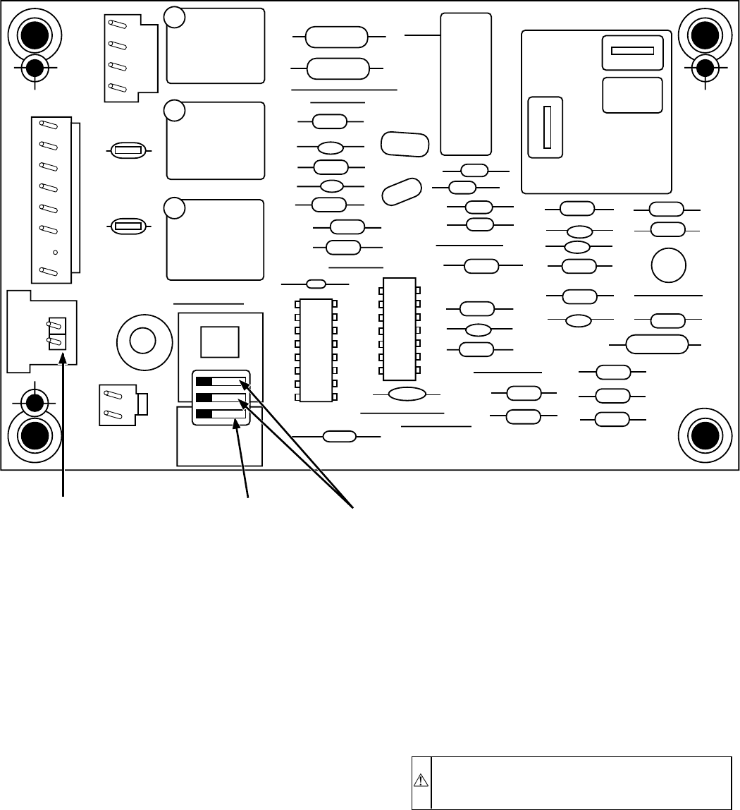
either heating or cooling. This enables owner to obtain timely
heat-pump service during heating season, reducing supplementary
electric heat costs, and during cooling season, reducing period of
heat discomfort.
The service alarm is an accessory device. Service alarm locks out
compressor under certain adverse operating conditions. System is
manually reset by shutting it off at thermostat subbase, then
turning it back on. If adverse condition is corrected, system
restarts.
One example of an adverse condition would be a system located in
a desert climate where high operating temperatures may cause
system to shut down on the high-pressure switch or on the
compressor internal overload.
Connect service alarm to outdoor-unit control-circuit-terminal
board. (See Fig. 25 and wiring diagram on unit.)
Connect all field line-power wires to unit in usual manner. Route
1 field line-power supply wire through metallic loop on bottom of
service alarm then to normal unit connection. Units with RLA of
less than 14 amps will require 2 passes through the metallic loop.
Refer to Fig. 25 or 26 for wiring connections for service alarm or
service alarm with solid-state cycle-protector accessories, when
used.
NOTE: The wire from the X terminal on the service alarm to L on
the outdoor terminal board, indoor terminal board, and thermostat
subbase is field-supplied and wired when using defrost controls
HK32FA003 or HK32FA006. When defrost control CES0110063
or CES0130024 is used, field-supplied wire from X terminal on
service alarm to L on indoor thermostat subbase is required.
Service alarm requires 2 inputs.
1. It must sense a 24v input from thermostat. As thermostat
calls for heating or cooling, it supplies 24v to service-alarm
device.
2. A current transformer (or induction loop) similar to a
clamp-on ammeter senses current draw in the compressor
lead. Induction loop must sense a minimum current draw
when thermostat is calling for heating or cooling.
NOTE: On a single-phase compressor, induction loop senses
current in common leg. On a 3-phase compressor, induction loop
senses current in any 1 of the phases.
WARNING: If service alarm needs replacing, shut off
all power to unit before attempting removal. Electrical
shock can cause personal injury or death.
Troubleshooting service-alarm device is easy. With thermostat
calling for heating or cooling and compressor running, indoor
thermostat light should be off. If on, check for wiring errors or
replace the service alarm.
To check for correct operation, shut off circuit breaker or discon-
nect switch to outdoor unit while it is running. Signal light on
thermostat should light. If this does not occur, check for wiring
errors or replace the service alarm.
XII. OUTDOOR THERMOSTAT(S)
The outdoor thermostat(s) is installed in the control box. The
sensing bulb(s) remain in the control box. Outdoor thermostat
brings on stages of electric heat as outdoor temperature and
Fig. 22—Defrost Control
A99442
OF2
CESO130076–00
OF1
ON
QUIET
SHIFT
120
30
60
60
30
90
INTERVAL TIMER OFF
P3
DFT
O R W2 Y C
T2 C C O
DFT
T1 Y P1 J1
SPEEDUP
Speedup
Pins Defrost interval
DIP switches
Quiet
Shift
—22—
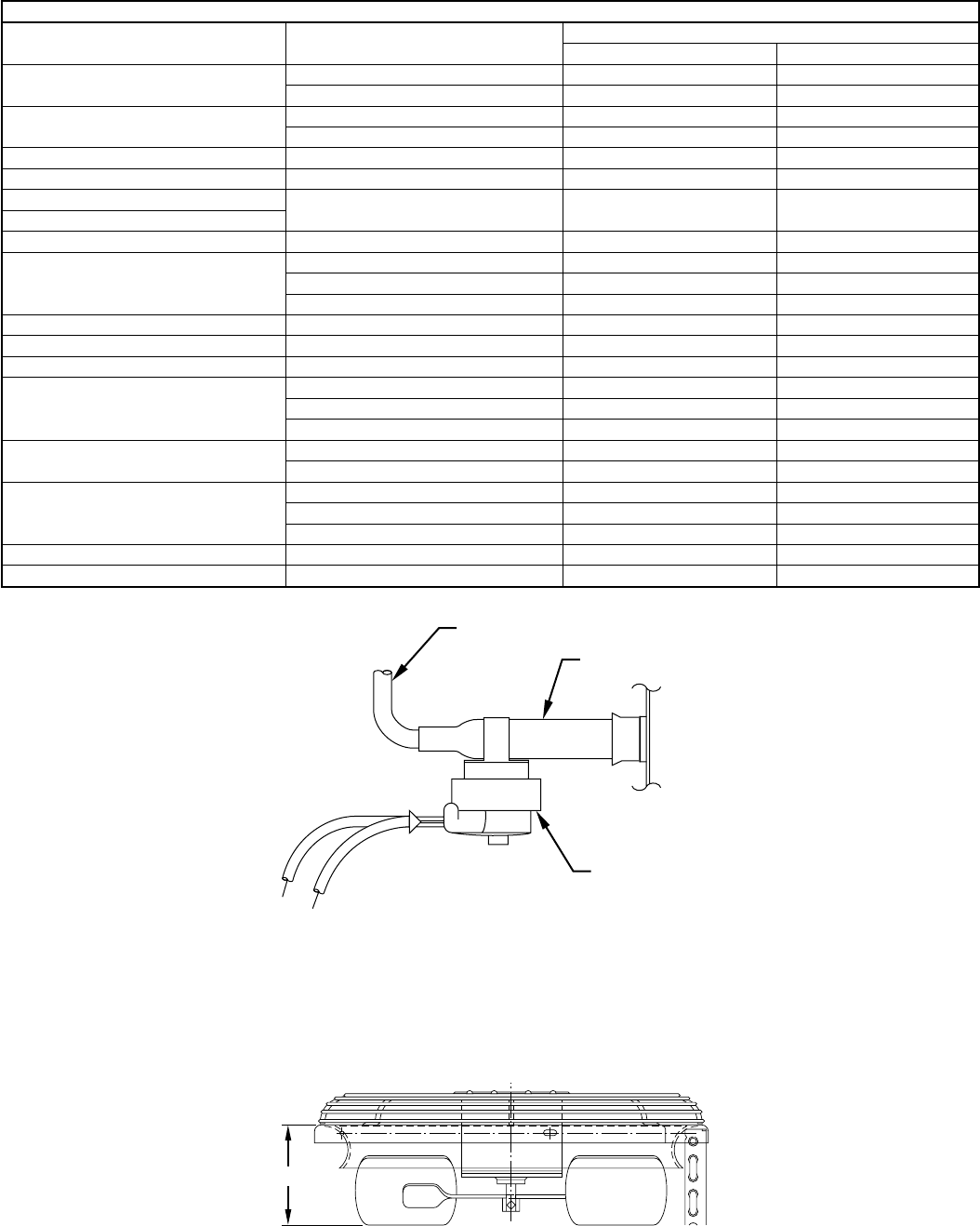
TABLE 12—FAN POSITION
AEROQUIET SYSTEM AND AEROMAX TOP
Fan Motor Part No. Fan Blade Part No. Dimension A (In.)
Brookside Revcor
HC29GE208 LA01EB023 4–5/32 —
LA01EC019 5–1/8 —
HC31GE230/231 LA01EA026 4–5/8 —
LA01RA015 4–7/8 4–5/8
HC33GE208 LA01EW049 5–1/4 —
HC33GE232 LA01RA015 4–29/32 4–17/32
HC34GE231 LA01RA015 5–5/32 4–25/32
HC34GE460
HC35GE208 LA01EW048 4–15/16 —
HC35GE232
LA01EA025 5–7/8 —
LA01RA024 5–11/32 5–3/32
LA01RA026 5–9/16 4–11/16
HC37GE208 LA01EA025 6–1/8 6–1/8
HC37GE230 LA01EW046 6–5/32 6–1/8
HC38GE221 LA01EA031 7–25/32 —
HC39GE232
LA01EC018 5–11/16 —
LA01RA026 5–1/2 4–3/4
LA01EA036 5–9/16 —
HC39GE234 LA01EA024 5–3/32 4–27/32
LA01EC018 5–1/2 —
HC39GE461
LA01EA036 6–1/16 —
LA01EC018 6–1/4 —
LA01RA026 6–1/16 5–7/32
HC40GE230 LA01EA024 5–9/32 5–11/32
HC40GE461 LA01EA024 5–27/32 5–19/32
Fig. 23—Defrost Thermostat Location
A97517
FEEDER TUBE
DEFROST
THERMOSTAT
STUB TUBE
Fig. 24—Fan Position
A91428
BASKET TOP
A
—23—
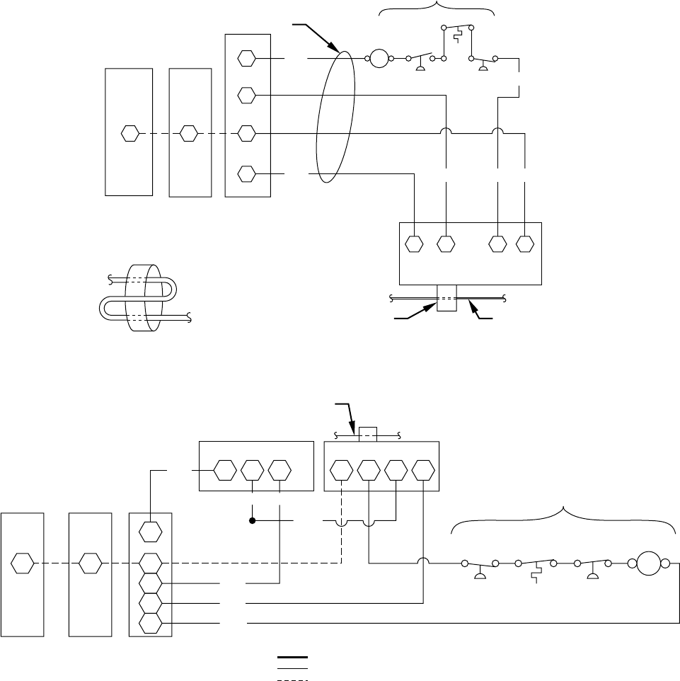
heat-pump output drops. Setting at which thermostat closes is
variable, depending on design of system. It is set at time of
installation and should not be changed without cause. Up to 2
outdoor thermostats may be installed. Some systems may not have
any thermostat. An outdoor thermostat can also be used to lock out
compressor operation at low ambients in condensing unit not
equipped with low-ambient control.
Although these devices are installed in control circuit (24v), turn
off all power to unit before attempting to troubleshoot thermostat.
Use a standard ohmmeter to check for continuity through thermo-
stat. If you suspect thermostat is out of calibration, use calibrated
electronic thermometer to determine correct outdoor temperature.
Turn thermostat dial knob until switch closes. Observe this using
ohmmeter across switch. Read temperature setting when switch
closes. It should be close to reading observed using electronic
thermometer. Any setting within ± 5°F is acceptable.
XIII. COMPRESSOR PLUG
The compressor electrical plug provides a quick-tight connection
to the compressor terminals. The plug completely covers the
compressor terminals, and the mating female terminals are com-
pletely encapsulated in the plug. Therefore, the terminals are
isolated from any moisture so corrosion and resultant pitted or
discolored terminals are reduced. The plug is oriented to the relief
slot in the terminal box so the cover cannot be secured if wires are
not positioned in slot, assuring correct electrical connection at the
compressor. The plug can be removed by simultaneously pulling
while ″rocking″the plug. However, these plugs are specialized and
vary in terminal orientation in the plug. Therefore, plugs can be
used on only the specific compressor or group as shown in Fig. 27.
For the Carlyle and Bristol compressors in Fig. 27, the triangle
formed by the fusite terminals points down, and the plug is
likewise oriented. The fusite terminals and plug-terminal orienta-
Fig. 25—Service Alarm Wiring Connections
A88340
Y
L
C
LL
C
BLK
THERMOSTAT
SUBBASE INDOOR
UNIT
TERMINAL
BOARD
OUTDOOR
UNIT
TERMINAL
BOARD
PASS SUPPLY WIRE THROUGH
METALLIC LOOP TWICE ON
UNITS WITH NAMEPLATE
RLA OF 14 AMPS OR LESS.
C
21 3 X
YEL
SERVICE ALARM
ORN REDYEL
BRN YEL
LPS
DTS
HPS
BLUBLU
HIGH AND/OR LOW PRESSURE
AND/OR DISCHARGE TEMPERATURE
SWITCH (IF USED)
24-VOLT WIRING
*METALLIC
LOOP ONE FIELD
LINE VOLTAGE
SUPPLY WIRE
Fig. 26—Wiring Connections for Service Alarm and Cycle Protector
A88339
A88339
T1
FIELD LINE VOLTAGE SUPPLY WIRE
T2 T3 X 3 2 1
Y
L
C
C
C
LL C
YEL
BLK
BLK
BRN
THERMOSTAT
SUBBASE INDOOR
UNIT
TERMINAL
BOARD
OUTDOOR
UNIT
TERMINAL
BOARD
ORN
BLKVIO
YEL
LPS
DTS
HPS
YEL BLU BLU
BRN
HIGH AND/OR LOW PRESSURE
AND/OR DISCHARGE TEMPERATURE
SWITCH (IF USED)
COMMON POTENTIAL
FACTORY WIRING (FIELD CONNECTED)
FIELD-SUPPLIED WIRING
CONTACTOR
CYCLE PROTECTOR SERVICE ALARM
C
—24—
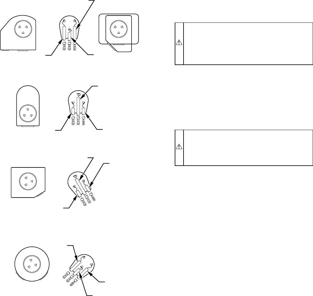
tion shown for the Tecumseh compressor is shown with the
triangle formed by the terminals pointing toward the top. The
configuration around the fusite terminals is the outline of the
terminal covers used on the specific compressors. The slot through
which the wires of the plug are routed is oriented on the bottom or
slightly to the left or right. The correct plug can be connected
easily to the compressor terminals and plug wires routed easily
through the slot in the terminal cover. Therefore, if a Carlyle or
Bristol compressor is substituted for a Tecumseh compressor, a
new plug must be installed. If the plug is not changed, proper
connection and routing of the plug wires through the terminal
cover will be impossible.
XIV. LOW-VOLTAGE TERMINALS
The low-voltage terminal designations, along with descriptions
and/or functions, are used on all split-system condensers and heat
pumps:
G—Energizes blower circuit from indoor thermostat.
E—Energizes emergency-heat relay.
W2—Energizes first-stage supplemental heat through defrost relay
(wht).
L—Energizes light on thermostat with service alarm.
W3—Energizes second- or third-stage supplemental heat.
R—Energizes 24v power from transformer (red).
Y—Energizes contactor for first-stage cooling or first-stage heat-
ing for heat pumps (yel).
O—Energizes reversing valve on heat pumps (orn).
C—Common side of transformer (blk).
RECIPROCATING COMPRESSOR
The compressor is the heart of the refrigeration system. It pumps
refrigerant through the system. If it malfunctions, system capacity
and efficiency could be negatively affected.
CAUTION: The compressor is an electrical (as well as
mechanical) device. Exercise extreme caution when
working near compressors. Power should be shut off, if
possible, for most troubleshooting techniques. Refriger-
ants in system present other safety hazards. Always wear
safety glasses and gloves when handling refrigerants.
Compressor failures are classified in 2 broad failure categories:
mechanical and electrical. Both types are discussed below.
I. MECHANICAL FAILURES
A compressor is a mechanical pump driven by an electric motor
contained in a welded or hermetic shell. In a mechanical failure,
motor or electrical circuit appears normal, but compressor does not
function normally.
CAUTION: Exercise extreme caution when reading
compressor currents when high-voltage power is on.
Correct any of the problems described below before
installing and running a replacement compressor. Wear
safety glasses and gloves when handling refrigerants.
LOCKED ROTOR
In this type of failure, compressor motor and all starting compo-
nents are normal. When compressor attempts to start, it draws
locked-rotor current and cycles off on the internal protection.
Locked-rotor current is measured by applying a clamp-on ammeter
around common (blk) lead of the compressor on a single-phase
compressor, or any 1 of the leads on a 3-phase compressor. Current
drawn when it attempts to start is then measured. LRA (locked-
rotor amp) value is stamped on compressor nameplate.
If compressor draws locked-rotor amps and all other external
sources of problems have been eliminated, compressor must be
replaced. Because compressor is a sealed unit, it is impossible to
determine exact mechanical failure. However, complete system
should be checked for abnormalities such as incorrect refrigerant
charge, restrictions, insufficient airflow across indoor or outdoor
coil, and so forth, which could be contributing to the failure.
RUNS, DOES NOT PUMP
In this type of failure, compressor motor runs and turns compres-
sor, but compressor does not pump the refrigerant. A clamp-on
ammeter on common leg of a single-phase compressor, or any 1
lead of a 3-phase compressor, shows a very low current draw,
much lower than RLA (rated load amps) value stamped on
compressor nameplate. Because no refrigerant is being pumped,
there is no return gas to cool compressor motor. It eventually
overheats and shuts off on its internal protection.
RUNS, DOES NOT PUMP, HIGH-TO-LOW SIDE LEAK
Fig. 27—Compressor Plug
A94002
LEAD 1
BLK. LEAD 2
YEL.
CS
R
C
R
BRISTOL
COPELAND
CARLYLE
SC
R
S
LEAD 3
BLUE
LEAD 2
YEL.
LEAD 3
BLUE
C
R
S
TECUMSEH
C
S
R
LEAD 1
BLK.
LEAD 3
BLUE
C
SR
TECUMSEH
C
SR
LEAD 1
BLK.
LEAD 2
YEL.
LEAD 1
BLK.
LEAD 2
YEL.
LEAD 3
BLUE
C
SR
MILLENNIUM
C
S
R
—25—
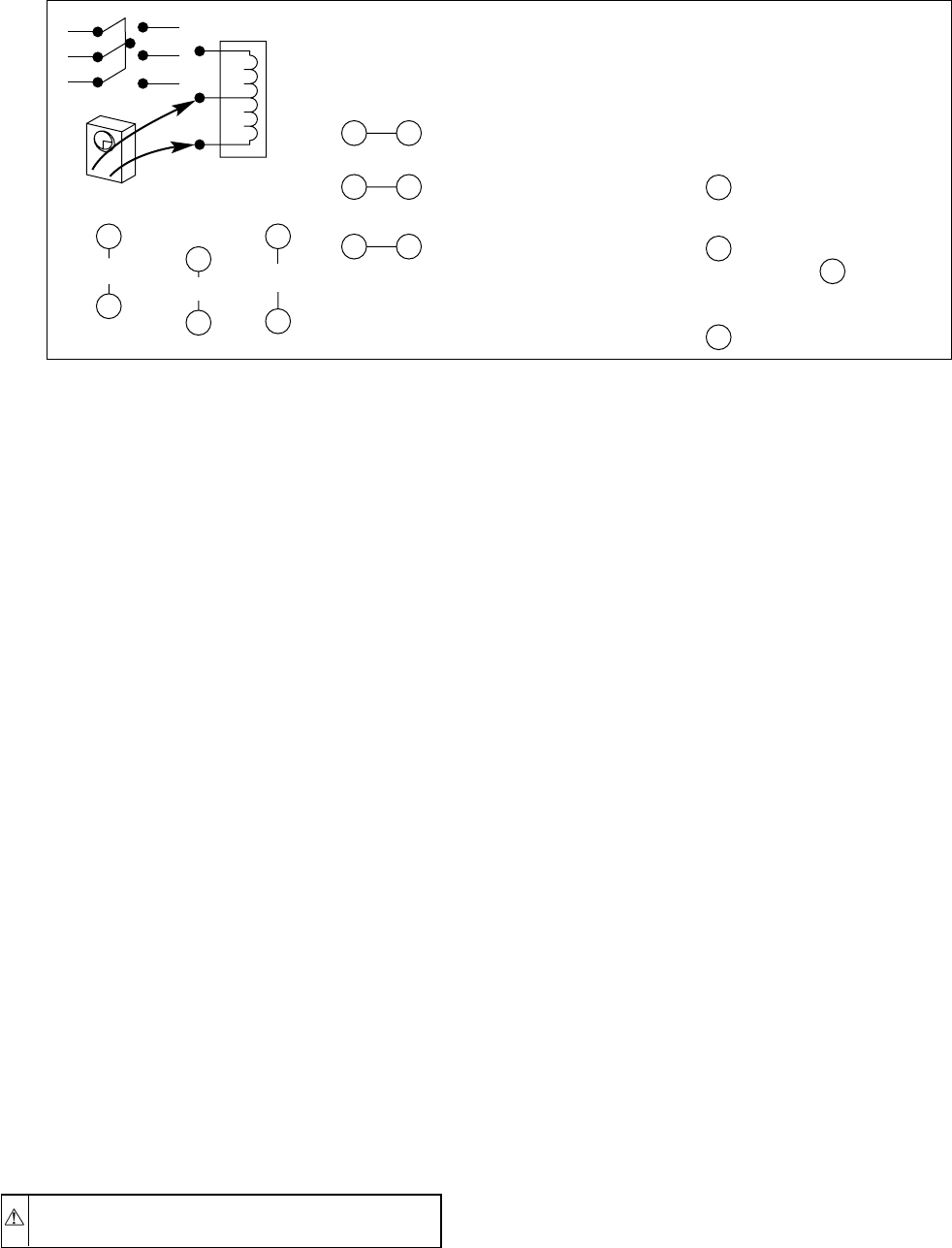
In this type of failure, compressor motor runs and turns compres-
sor, and compressor is pumping. Usually, an internal problem such
as blown head gasket or broken internal-discharge line causes
compressor to pump hot discharge gas back into its own shell
rather than through system.
Using pressure gages on service valves shows high suction and
low discharge pressure readings. Motor currents are lower than
normal. Because hot gas is being discharged into shell, the shell
becomes hot. The hot gas causes compressor motor to cycle off on
its internal protection.
RUNS AND PUMPS, LOW CAPACITY
This failure type is difficult to pinpoint because extent of damage
varies. Compressor is a pump with internal valves that enable
compressor to pump properly. The cylinder has a set of suction and
discharge valves. Any of these parts may become damaged or
broken, causing loss in pumping capacity. Severity of damage
determines amount of capacity loss. Use pressure gages to find any
abnormal system pressures if system charge and other conditions
are normal.
An owner may complain that a unit is not handling the building’s
heating or cooling load. The compressor current draw may be
abnormally low or high. Although this type of failure does occur,
all other possible causes of capacity loss must be eliminated before
condemning compressor.
NOISY COMPRESSOR
Noise may be caused by a variety of internal problems such as
loosened hardware, broken mounting springs, etc. System prob-
lems such as overcharged compressor (especially at start-up) or too
much oil in compressor may also cause excessive noise. Excess oil
in compressor is normally encountered only after a replacement
compressor has been added without purging oil from previous
compressor. As new compressor pumps, excess oil in system
returns and adds to volume already present, causing noise.
COMPRESSOR LEAKS
CAUTION: Use safety glasses and gloves when han-
dling refrigerants.
Sometimes a leak is detected at weld seam around girth of
compressor or a fitting that joins compressor shell. Many of these
leaks can be repaired and the compressor saved if correct proce-
dure is followed.
1. Turn off all power to unit.
2. Remove and recover all refrigerant from system so that
gage pressures are 0 psi.
3. Clean area around leak to bare metal.
4. Apply flux and repair joint with silver solder. Do not use
low-temperature solder such as 50-50.
5. Clean off excess flux, check for leaks, and apply paint over
repaired area to prevent corrosion.
Do not use this method to repair a compressor leak due to severe
corrosion. Never attempt to repair a compressor leaking at electric
terminals. This type of failure requires compressor replacement.
II. ELECTRICAL FAILURES
The compressor mechanical pump is driven by an electric motor
within its hermetic shell. In electrical failures, compressor does not
run although external electrical and mechanical systems appear
normal. Compressor must be checked electrically for abnormali-
ties.
Before troubleshooting compressor motor, review this description
of compressor motor-terminal identification.
SINGLE-PHASE MOTORS
To identify terminals C, S, and R:
1. Turn off all unit power.
2. Short the run and start capacitors to prevent shock.
3. Remove all wires from motor terminals.
4. Read resistance between all pairs of terminals using an
ohmmeter on 0-10 ohm scale.
5. Determine 2 terminals that provide greatest resistance
reading.
Through elimination, remaining terminal must be common (C).
Greatest resistance between common (C) and another terminal
indicates start winding because it has more turns. This terminal is
start (S). Remaining terminal will be run winding (R). (See Fig.
28.)
NOTE: If compressor is hot, allow time to cool and internal line
break to reset. There is an internal line-break protector which must
be closed.
THREE-PHASE MOTORS
Resistance readings between all 3 sets of windings should be the
same.
All compressors are equipped with internal motor protection. If
motor becomes hot for any reason, protector opens. Compressor
should always be allowed to cool and protector to close before
troubleshooting. Always turn off all power to unit and disconnect
leads at compressor terminals before taking readings.
Fig. 28—Identifying Internal Connections
A88344
POWER OFF!
OHMMETER
0-10Ω SCALE
5.2Ω0.6Ω5.8Ω
DEDUCTION:
(EXAMPLE)
TO DETERMINE INTERNAL CONNECTIONS OF SINGLE-
PHASE MOTORS (C,S,R) EXCEPT SHADED-POLE
?
?
?
1
2
2
3
1
3
12
32
1 3 (GREATEST RESISTANCE)
5.8Ω (OHM)
(SMALLEST RESISTANCE)
0.6Ω
(REMAINING RESISTANCE)
5.2Ω
2
2
3
1
IS COMMON (C)
BY ELIMINATION
IS COMMON,
THEREFORE, IS
START WINDING (S)
RUN WINDING (R)
START WINDING (S)
IS RUN WINDING (R)
—26—
Most common motor failures are due to either an open, grounded,
or short circuit. Directions below are specifically for single-phase
units, however, they also apply to 3-phase compressors. When a
single-phase compressor fails to start or run, 3 tests can help
determine the problem. First, all possible external causes should be
eliminated, such as overloads, improper voltage, pressure equal-
ization, defective capacitor(s), relays, wiring, and so forth. Com-
pressor has internal line-break overload, so be certain it is closed.
OPEN CIRCUIT
To determine if any winding has a break in the internal wires and
current is unable to pass through:
1. Be sure all power is off.
2. Discharge all capacitors.
3. Remove wires from terminals C, S and R.
4. Check resistance from C-R, C-S and R-S using an ohmme-
ter on 0-1000 ohm scale.
Because winding resistances are usually less than 10 ohms, each
reading appears to be approximately 0 ohm. If resistance remains
at 1000 ohms, an open or break exists, and compressor should be
replaced.
CAUTION: Be sure internal line-break overload is not
temporarily open.
GROUND CIRCUIT
To determine if a wire has broken or come in direct contact with
shell, causing a direct short to ground:
1. Be sure all power is off.
2. Discharge all capacitors.
3. Remove wires from terminals C, S, and R.
4. On hermetic compressors, allow crankcase heaters to re-
main on for several hours before checking motor to ensure
windings are not saturated with refrigerant.
5. Use an ohmmeter on R X 10,000 ohm scale. A megohm-
meter may be used in place of ohmmeter. Follow manufac-
turer’s instructions.
6. Place 1 meter probe on ground or on compressor shell.
Make a good metal-to-metal contact. Place other probe on
terminals C, S, and R in sequence.
7. Note meter scale.
8. If reading of zero or low resistance is obtained, motor is
grounded. Replace compressor.
A 1 ton or less capacity compressor is probably grounded if
resistance is below 1 million ohms. On larger-sized, single-phase
compressors, resistance to ground should not be less than 1000
ohms per volt of operating voltage.
Example:
230 volts X 1000 ohms/volt = 230,000 ohms minimum.
SHORT CIRCUIT
To determine if any wires within windings have broken through
their insulation and made contact with other wires, thereby
shorting all or part of the winding(s), be sure the following
conditions are met:
1. Correct motor-winding resistances must be known before
testing, either from previous readings or from manufactur-
er’s specifications.
2. Temperature of windings must be as specified, usually
about 70°F.
3. Resistance-measuring instrument must have an accuracy
within±5to10percent. This requires an accurate ohmme-
ter, such as a Wheatstone bridge or null balance-type
instrument.
4. Motor must be dry or free from direct contact with liquid
refrigerant.
MAKE THIS CRITICAL TEST
(Not advisable unless above conditions are met.)
1. Be sure all power is off.
2. Discharge all capacitors.
3. Remove wires from terminals C, S, and R.
4. Place instrument probes together and determine probe and
lead wire resistance.
5. Check resistance readings from C-R, C-S, and R-S.
6. Subtract instrument probe and lead resistance from each
reading.
If any reading is within ± 20 percent of known resistance, motor is
probably normal. Usually a considerable difference in reading is
noted if a turn-to-turn short is present.
III. SYSTEM CLEANUP AFTER BURNOUT
CAUTION: Turn off all power to unit before proceed-
ing. Wear safety glasses and gloves when handling
refrigerants. Acids formed as a result of motor burnout
can cause burns.
NOTE: To analyze level of suspected contamination from com-
pressor burnout, use Total Test. See your distributor/branch.
Some compressor electrical failures can cause motor to overheat.
When this occurs, by-products, which include sludge, carbon, and
acids, can contaminate system. If burnout is severe enough, system
must be cleaned before replacement compressor is installed. The 2
types of motor burnout are classified as mild or severe.
In mild burnout, there is little or no detectable odor. Compressor
oil is clear or slightly discolored. An acid test of compressor oil
will be negative. This type of failure is treated the same as
mechanical failure. Liquid-line strainer should be removed and
liquid-line filter drier installed.
In a severe burnout, there is a strong, pungent, rotten-egg odor.
Compressor oil is very dark. Evidence of burning may be present
in tubing connected to compressor. An acid test of compressor oil
will be positive. Complete system must be reverse flushed with
refrigerant. Check-Flo-Rater™or TXV must be cleaned or re-
placed. In a heat pump, accumulator and reversing valve are
replaced. These components are also removed and bypassed during
reverse-flushing procedure. Remove and discard liquid-line
strainer. After system is reassembled, install liquid-line and
suction-line filter driers. Run system for 2 hrs. Discard both driers
and install new liquid-line drier only.
IV. COMPRESSOR REMOVAL AND REPLACEMENT
Once it is determined that compressor has failed and the reason
established, compressor must be replaced.
CAUTION: Wear safety glasses and gloves when han-
dling refrigerants and when using brazing torch.
1. Shut off all power to unit.
2. Remove and recover all refrigerant from system until
pressure gages read zero psi. Use all service ports.
3. Disconnect electrical leads from compressor. Disconnect or
remove crankcase heater and remove compressor-holddown
bolts.
4. Cut compressor from system with tubing cutters. Do not use
brazing torch for compressor removal. Oil vapor may ignite
when compressor is disconnected.
—27—
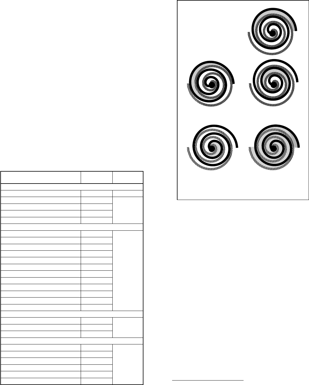
5. Scratch matching marks on stubs in old compressor. Make
corresponding marks on replacement compressor.
6. Use torch to remove stubs from old compressor and to
reinstall them in replacement compressor.
7. Use copper couplings to tie compressor back into system.
8. Evacuate system, recharge, and check for normal system
operation.
9. Copeland CR-6 and scroll compressors have copper-plated,
steel-suction ports. Excess heat during brazing will burn off
copper plating. See Brazing section for additional informa-
tion.
COPELAND SCROLL COMPRESSOR
I. FEATURES
The scroll compressor pumps refrigerant through the system by the
interaction of a stationary and an orbiting scroll. (See Fig. 29.) The
scroll compressor has no dynamic suction or discharge valves, and
it is more tolerant of stresses caused by debris, liquid slugging, and
flooded starts. Due to the design of the scroll compressor, the
internal compression components unload (equalize pressure) on
shutdown. The white oil (Sontex 200LT) used in the scroll is
compatible with 3GS oil, which can be used if additional oil is
required. (See Table 13 for oil recharge requirements.)
II. TROUBLESHOOTING
Troubleshooting mechanical or electrical problems in a scroll
compressor is the same as for a reciprocating compressor, except
that a scroll compressor should never be allowed to pump into a
vacuum. If a pumpdown procedure is used, the scroll compressor
is capable of pumping into a vacuum very quickly, which could
cause fusite arcing and compressor failure. See Step IV of
Reciprocating Compressor section for removal and replacement.
III. DISCHARGE THERMOSTAT
Some scroll compressors have a discharge thermostat that recip-
rocating compressors do not have. This thermostat is mounted in a
well in the top of the compressor shell to sense if the discharge
temperature reaches 290°F and shuts down the compressor to
prevent damage to it. When the temperature of the thermostat
reaches 140°F, power is restored to the compressor.
To determine if the thermostat is operating properly, either attach
the thermocouple of an electronic thermometer to the dome of the
compressor near the thermostat, or remove the thermostat and
place the thermocouple inside the well. The electronic thermom-
eter must be capable of reading at least 300°F. Start the unit and let
it run for at least 15 minutes to obtain normal operating conditions.
Watch the thermometer to see if it is approaching 270°F. If the
thermocouple is located on the dome near the discharge thermo-
stat, there could be a 20°difference between well and dome
temperatures. If the temperature approaches 270°F, repair system
problem, such as low charge, blocked condenser coil, and so forth.
If the temperature does not approach 270°F, replace discharge
thermostat.
Replacing Discharge Thermostat
To replace the discharge thermostat, refer to the Installation
Instructions packaged with the replacement discharge thermostat
kit. (See Fig. 30.)
IV. DISCHARGE SOLENOID VALVE
Some larger units equipped with scroll compressors contain a
solenoid valve that is piped between the discharge tube and suction
tube of the compressor. The purpose of the solenoid valve is to
TABLE 13—COMPRESSOR OIL RECHARGE
COMPRESSOR MODEL RECHARGE
(FL. OZ.) OIL TYPE
Carlyle/Scroll
″J″Type 44 Suniso 3GS
SC, SRD450AC 34 Zerol 150
w/3 percent
Syn-O-Ad
SR 52
SRH482, SRY482 68
SRH602, SRY602 70
Copeland
CRG3, CRH3, CRJ3, CRK3, CRL3 51
Suniso 3GS
CRN5, CRP5, CRT5, CTH1, CTL1 66
CRC4, CRZ4 36
CR16K6 THROUGH CR42K6 42
*ZR18K1 19
*ZR23K1, ZR28K1 24
*ZR34K1 30
*ZR40K1 34
*ZR49K1-PFV 56
*ZR49K2-TF5, ZR49K2-TFD 56
*ZR61K2-PFV 56
*ZR61K2-TF5, ZR61K2-TFD 66
Tecumseh
AV55 50
Suniso 3GSAW55 30
AG 60
Bristol
H23A 52
Suniso 3GS
H23B 37
H24A3, H24A4 47
H24A5 52
H25A, H26A 62
H25B, H26B, H29B 32
*Copeland scrolls are charged initially with Sontex 200LT white oil. Since this
oil is not commercially available, use 3GS.
Fig. 29—Scroll Compressor Refrigerant Flow
A90198
Scroll Gas Flow
Compression in the scroll is
created by the interaction of
an orbiting spiral and a
stationary spiral. Gas enters
an outer opening as one of the
spirals orbits.
The open passage is sealed off
as gas is drawn into the spiral.
By the time the gas arrives at
the center port, discharge
pressure has been reached.
Actually, during operation, all
six gas passages are in various
stages of compression at all
times, resulting in nearly con-
tinuous suction and discharge.
As the spiral continues to orbit,
the gas is compressed into an
increasingly smaller pocket.
1
23
54
—28—
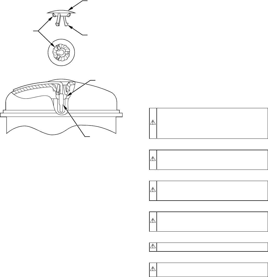
cause a rapid pressure equalization around the compressor, thus
reducing the normal shutdown sound created by reverse rotation of
the scroll. The solenoid valve is normally closed and is wired
across high-voltage line 1 to load terminals of the contactor. (See
Fig. 18.) The solenoid-valve assembly also requires a check valve
piped in the discharge tube between the solenoid-valve tee and the
condenser coil, or reversing valve on heat pumps. The purpose of
the check valve is to prevent refrigerant from bypassing through
the solenoid valve into the suction tube when the unit cycles off.
MILLENNIUM SCROLL COMPRESSOR
I. FEATURES
The scroll compressor pumps refrigerant through the system by the
interaction of a stationary and an orbiting scroll. (See Fig. 29.) The
scroll compressor has no dynamic suction or discharge valves, and
it is more tolerant of stresses caused by debris, liquid slugging, and
flooded starts. The Millennium scroll varies from the Copeland
scroll in that the Millennium has a shutdown flapper valve located
between the scroll plates and the discharge head, whereas the
Copeland has a check device at the discharge connection after the
discharge head. The Copeland discharge head unloads when the
compressor shuts down. The scroll plate actually runs backwards
while it unloads.A1to3second unloading of refrigerant occurs.
The Millennium flapper valve eliminates the refrigerant unloading
by not allowing the discharge head to run backwards because of its
location. The Millennium scroll compressor uses Zerol 150 oil
with 3 percent Syn-O-Ad and is the only oil recommended for oil
recharge. See Table 13 for recharge requirements.
II. COMPRESSOR PROTECTION
Millennium scroll compressors are protected by an internal line-
break mounted on the motor windings. Internal protectors respond
to overcurrent and high temperature. These protectors are
automatic-reset devices containing a snap-action, bi-metal switch.
III. TROUBLESHOOTING
Troubleshooting mechanical and electrical problems in a scroll
compressor is similar to a reciprocating compressor, except that a
scroll compressor should never be allowed to pump into a vacuum.
The scroll compressor is capable of pumping into a vacuum very
quickly, which could cause fusite arcing and compressor failure.
See Step IV of Reciprocating Compressor section for removal and
replacement.
IV. SCROLL COMPRESSOR, 3–PHASE MONITOR
CES0130075 —PHASE MONITOR
This control is factory-installed on all 3–phase, scroll compressor
models. (See Fig. 31 and 32.) On start-up, the control will energize
the pilot relay for 2 seconds. The monitor will check for correct
compressor rotation. If rotation is correct, unit will continue to run.
If rotation is incorrect, the control will break the 24vac power at
the contactor and an LED light on the control will flash. If LED is
flashing, turn off power, reverse L1 and L3 field-power leads, and
restart unit. This control will check incoming power at every
restart.
TWO-SPEED SYSTEM
I. CAUTIONS AND WARNINGS
CAUTION: For proper unit operation and reliability, the
2-speed units must be installed with the factory-supplied
balance port, hard shutoff TXV. Do not install with
indoor coils having piston or capillary-tube metering
devices.
CAUTION: Do not install equivalent interconnecting
tubing lengths greater than 100 ft. Do not decrease or
increase interconnecting tubing diameters.
CAUTION: To avoid electrical shock, bleed resistor
must be connected across run capacitor. Replace if
missing or damaged.
CAUTION: Contactor is mechanically interlocked. Do
not disable mechanical interlock. Compressor damage
may occur.
WARNING: Contactor control voltage is 240vac.
WARNING: Do not attempt to operate this equipment
below 55°F outdoor ambient temperature.
NOTE: Sections that follow describe the 598A Series B and
698A Series B products, which started production March, 1994.
For 598A Series A and 698A Series A products, refer to the
Split-System Service Manual dated 3–1–94, Catalog No. BDP
3356–115.
II. SYSTEM FUNCTIONS
COOLING OPERATION
The 2-speed products utilize a 2-stage-cooling indoor thermostat.
With a call for first-stage cooling (Y1), the outdoor fan and
low-speed compressor are energized. If low speed cannot satisfy
the cooling demand, high speed will be energized (Y1 and Y2) by
the second stage of the indoor thermostat. The thermostat has a 2°
differential between first and second stages. After second stage is
satisfied, the unit returns to low-speed operation, until first stage is
satisfied, or until second stage is again required.
Fig. 30—Location of Discharge Thermostat
A90198
PLASTIC CAP
PRONG
BLUE SEALANT
GROMMET
THERMAL GREASE THERMOSTAT
—29—
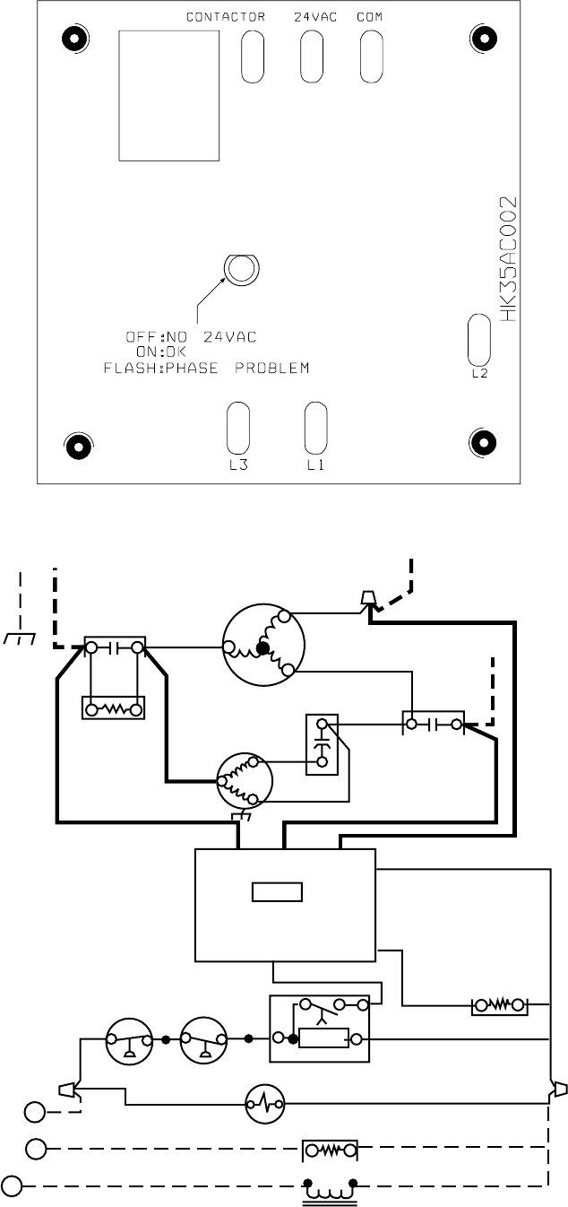
Fig. 31—CES0130075 3–Phase Monitor Board
A00010
Fig. 32—CESO130075 3–Phase Monitor Wiring Diagram
A00011
EQUIP
GND
CONT
L1 COMP
11 21
T1 T2
T3
*CH
L2
L3
13
23
OFM
CAP CONT
L1 L3 L2 C
YCONT
LOGIC
CESO130075
CONT
T2
T3T1
*LPS
*HPS
*LLS CTD
IFR
RC
Y
G
R
INDOOR
THERMOSTAT EXTERNAL POWER SUPPLY 24 V
LOGIC
—30—
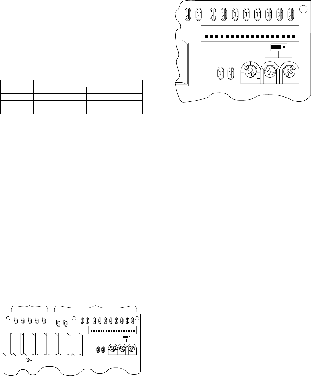
HEATING OPERATION (HEAT PUMP ONLY)
The 2-speed products utilize a 2-stage-heating indoor thermostat.
The first stage of heating is heat-pump operation (Y1). Auxiliary
backup heat is controlled by second stage (W2). There is a 2°
differential between first and second stage. The control board
determines the compressor speed based on ambient temperature.
See Table 14 for ambient temperatures at which speed changes
occur. When high-speed, heat-pump heating is required, the
control provides a Y2 (24vac) signal back to the thermostat to
energize high-speed-indicator LED.
LED FUNCTION LIGHTS
When using the factory-authorized indoor thermostats with the
2-speed outdoor units, there are 2 locations where system-function
LED-indicator lights are available. The indoor thermostat provides
indicator lights for high- and low-speed operation, system mal-
function, and auxiliary heat for heat pumps. The 2-speed control
board has an LED which provides signals for several system
operations. See Table 15 for LED functions, indicator locations,
and definitions. Table 15 also provides the order of signal
importance if more than 1 signal should occur. The signal to the
indoor thermostat is supplied by the low-voltage ″L″lead.
THREE-SECOND TIME DELAY
Any time the control receives a 24v input, such as Y1 or Y2, there
is a 3-sec time delay before the control function is initiated. This
helps prevent nuisance trips and thermostat ″jiggling.″
ONE-MINUTE SPEED-CHANGE TIME DELAY
When the compressor changes speeds from high to low or low to
high, there is a 1-minute time delay before the compressor restarts.
The outdoor fan motor remains running.
FIVE-MINUTE TIME DELAY
The 2-speed-control logic contains a 5-minute time delay that
prevents the unit from short cycling after a thermostat-off cycle or
power interruption. The unit can be forced to operate immediately
by momentarily touching a jumper between the speed-up terminals
of the control board. (See Fig. 33 and 34.) The speed-up feature
will not bypass any other function or time delay.
TWO-MINUTE LOW-SPEED MINIMUM
If the unit has not operated within the past 30 minutes, the unit
operates for a minimum of 2 minutes in low speed upon the next
thermostat high or low demand.
CRANKCASE-HEATER OPERATION
The 2-speed control energizes the crankcase heater during the
unit’s off cycle when the outdoor ambient is below 75°F.
OUTDOOR FAN-MOTOR OPERATION
The 2-speed control energizes the outdoor fan any time the
compressor is operating. The outdoor fan remains energized during
the 1-minute, speed-change time delay and if a pressure switch or
compressor PTC overload should trip.
If the outdoor fan motor won’t run, check the header-pin housing.
(See Fig. 37.) There should be NO jumper wire between Terminals
15 and 16.
Heat Pumps
After the termination of a defrost cycle, the outdoor fan delays
come on for 20 sec. This allows the refrigeration system to recover
the outdoor coil heat and minimize the ″steam cloud″effect.
SECOND-STAGE LATCHING
When low-speed cooling operation no longer satisfies the first
stage of the indoor thermostat, the indoor temperature will increase
by 2°until second stage is energized. After high-speed cooling
satisfies second stage, it returns to low-speed cooling operation. If
desired, the installer may select to have high-speed cooling by
energizing Y1. High speed will stay energized until Y1 is satisfied.
This eliminates the temperature drop between the first and second
stages of indoor thermostat, holding room temperature closer to set
point.
To utilize this function, the unit capacity should be plotted versus
the heat gain of the structure, which provides the system’s balance
point when the structure requires high-speed capacity. (See Fig.
35.)
Second-stage latching can be selected by rotating the potentiom-
eter (POT) to the desired outdoor second-stage latching tempera-
ture (See Fig. 34.) The temperatures that can be selected are 85°,
90°,95°, 100°, and 105°F. The POT is factory set at 105°F.
ZONE SELECTION
If the stage–2 latch POT is set to ZONE position, the compressor
operating speed in either heat or cool mode is determined by the
Y1 and/or Y2 inputs. The system operates in low speed with a Y1
input and high speed with Y2 or Y1-and-Y2 input. This allows the
multistage-zoning system to determine what speed is needed
regardless of outdoor temperature or switchover point.
DEFROST TIME SELECTION
The defrost interval can be field selected, depending on local or
geographic requirements. It is factory set at 90 minutes and can be
changed to either 30 or 50 minutes by rotating the defrost-time
POT. (See Fig. 34.)
TABLE 14—AMBIENT TEMPERATURE FOR HIGH- AND
LOW-SPEED OPERATION
UNIT
SIZE AMBIENT TEMPERATURE (°F)
High Speed Low Speed
036 30 or less 31 or greater
048 33 or less 34 or greater
060 40 or less 41 or greater
Fig. 33—Two-Speed Control Board
A93569
HIGH VOLTAGE LOW VOLTAGE
L2 LO HI CCH ODF
OC
LM1 LM2 DFT1 DFT2 T1 T2 S2 S1 PW2 PW1
P1118
SPEED-UP
STAGE 2
LATCH DEFROST
TIME BALANCE
POINT
K7K6K5K4K3K2K1
LED 1
FURN INT
OFF ON
Fig. 34—Speedup Terminals
A93568
LM1 LM2 DFT1 DFT2 T1 T2 S2 S1 PW2 PW1
P1118
SPEED-UP
STAGE 2
LATCH DEFROST
TIME BALANCE
POINT
K7
ZONE
OFF105
100
95
90
85
FURN INT
OFF ON
4540
35
30
25
20
10 15
90
30
50
—31—
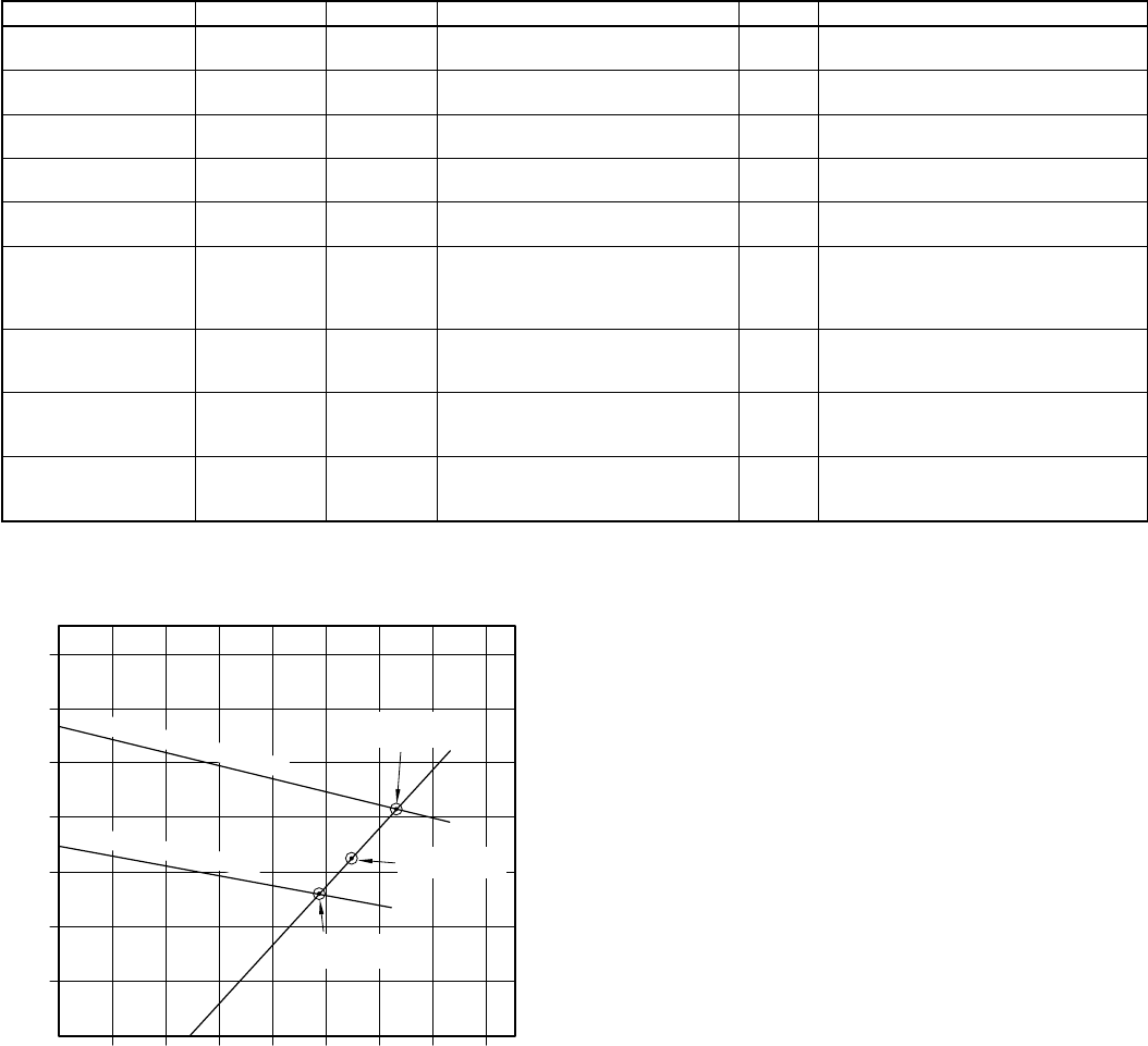
DEFROST
The 2-speed control logic for the defrost function is the standard
time and temperature initiated, time or temperature terminated.
Defrost occurs only at outdoor temperatures less than 50°F. The
control initiates defrost when the outdoor coil thermistor is 30°F(±
2) or less, and the selected defrost time (interval) has been
accumulated during unit operation. Termination occurs when the
coil thermistor reaches 80°F (± 5) or the defrost period reaches a
maximum of 10 minutes.
Defrost always occurs in high speed unless the stage–2 latch POT
is set at ZONE. During defrost the unit operates in high speed,
energizes the reversing valve (O) and auxiliary heat (W2), and
de-energizes the outdoor fan. Upon termination, there is a 20-sec
delay in the outdoor fan being energized. If the stage–2 latch POT
is set to ZONE and the heat pump is in low speed, it defrosts in low
speed.
FIELD-INITIATED FORCED DEFROST
By placing a jumper across the speedup terminals for a minimum
of 5 sec and then removing it, the unit initiates a defrost cycle. (See
Fig. 34.) The cycle occurs only if the outdoor ambient is less than
50°F, regardless of outdoor coil temperature. The cycle terminates
when the coil thermistor reaches 80°F(±5)orthedefrost period
reaches a maximum of 10 minutes.
FURNACE INTERFACE
This feature provides a heat-pump lockout upon a demand for
auxiliary heat (W2) and must be used when interfacing a heat
pump with a gas/oil furnace. Field selection of the furnace-
interface option is done by connecting the factory-supplied jumper
to the ON position of the 3 terminal connectors. (See Fig. 33.)
When the option is selected, the heat pump will be locked out of
operation any time there is a thermostat demand for W2 or the
outdoor ambient is below the balance-point POT-setting selection.
(See Fig. 34.) When the unit requires defrost, auxiliary heat (W2)
energizes the furnace. After defrost is terminated, the heat pump
shuts down and the furnace satisfies the thermostat. To utilize this
function, the economic and/or thermal balance point must be
determined. See the appropriate heat pump balance-point work-
sheet available from your distributor or branch.
BALANCE POINT
This feature can be used in 2 different options: furnace interface or
electric-heat staging. Refer to the Furnace Interface section for its
application. If the heat pump is installed with a fan coil with
multistages of electric heat, this option can be used to stage the
banks of heat by outdoor ambient. This eliminates the need for
accessory outdoor thermostats.
When using this option to stage electric heat, first stage is
energized by a W2 demand, and second stage is energized by a W3
demand. Select the W3 desired temperature by rotating the
balance-point POT. (See Fig. 34.) Temperatures that may be
selected are 10°,15°,20°,25°,30°,35°,40°, and 45°F. The POT
is factory set at 45°F.
LOW-SPEED HEATING WITH AUXILIARY HEAT
If the system is operating in low-speed heating and there is a
demand for auxiliary heat (W2), the system changes to high-speed
operation. W2 is energized unless the low-voltage control wiring is
configured as described in Fig. 36.
TABLE 15—FUNCTION LIGHT CODE AND DISPLAY LOCATION
CODE T’STAT UNIT DEFINITION * POSSIBLE CAUSE
Constant flash
No pause —XNo demand
Stand by 9—
1 flash
w/pause —X Low-speed operation 8 —
2 flashes
w/pause —X High-speed operation 7 —
3 flashes
w/pause X X Ambient thermistor failure 6 —
4 flashes
w/pause X X Coil thermistor failure 5 —
3 flashes
pause
4 flashes X X Thermistor out of range** 4
Thermistor drift, wrong location
Incorrect wiring
Incorrect refrigerant charge
Dirty indoor/outdoor coil
5 flashes
w/pause X‡XPressure switch trip
(LM1/LM2) 3Dirty outdoor coil
Refrigerant overcharge
Wrong indoor coil
6 flashes
w/pause†X X Compressor PTCs out of limit 2 Low refrigerant charge
Compressor mechanical problem
Dirty indoor/outdoor coil
Constant light
No pause
No flash X X Board failure 1 Equipment or electrical service
not grounded
*Function light signals order of importance; in case of multiple-signal request, 1 is most important.
†Signal at thermostat will occur after 3 consecutive attempted restarts and lockout has occurred.
‡Will be energized if pressure switch remains open for 1 hr.
**Check both thermistors to determine which is faulty.
Fig. 35—Typical Cooling Balance Points
A91282
10
20
30
40
50
60
70
50 60 70 80 90 100 110 120
BTU (1000'S)
HIGH SPEED CAPACITY
HIGH SPEED
BALANCE POINT
LOW SPEED
BALANCE POINT
LOW SPEED CAPACITY
TEMPERATURE (°F)
STRUCTURE
BALANCE POINT
—32—
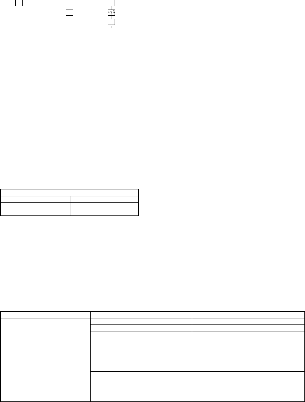
AUXILIARY HEAT (W2) LOCKOUT
In some areas, it is necessary to disable the auxiliary heat, except
for defrost, until the outdoor ambient is less than the structure’s
balance point. This is accomplished by using the low-voltage
wiring as shown in Fig. 36. Wire the 24vac W2 signal from the
indoor thermostat to W3 of the control, and W2 of the control to
W2 of the indoor unit. When the outdoor ambient is less than the
setting of the balance-point POT, the 24vac signal energizes the
auxiliary heat (W2) of the indoor unit.
EMERGENCY HEAT
If the 2-speed control receives a call for auxiliary heat (W2)
without a heat-pump heating (Y1) call, the second auxiliary stage
(W3) is energized. This ensures all available heat is energized if
the indoor thermostat is switched to emergency heat.
COMPRESSOR PTC-OVERLOAD PROTECTION
The control senses the resistance of the compressor internal
positive-temperature coefficient (PTC) overloads. If the resistance
of the PTCs is out of range, the control shuts off the unit until the
resistance range is acceptable. See Table 16 for compressor PTC
ranges.
When the control turns off the outdoor unit due to out-of-range
PTCs, the unit remains off for 15 minutes with the outdoor fan
running. After 15 minutes, the control checks the resistance every
5 minutes until it reaches the reset range. During this time, a
malfunction signal appears on the control board. If this happens,
remove the wires on control board at S1 and S2 and measure the
resistance across the leads. When the resistance reaches 8,400 to
10,000 ohms, system operation may be resumed. If the resistance
remains outside this range, a quick check of the leads at the
compressor should be made. Loose connections can cause inaccu-
rate readings. If a PTC trip occurs 3 times, the control will lock out
the outdoor-unit operation and provide malfunction signals at both
the control and indoor thermostat.
PRESSURE SWITCH PROTECTION
The outdoor unit is equipped with high- and low-pressure
switches, wired in series. If a pressure switch opens, the control
provides a 5-minute time delay in outdoor unit operation with the
outdoor fan running. A malfunction signal appears on the control
when a pressure switch opens. If the switch remains open for 1 hr
or longer, a malfunction signal is provided at the L terminal of the
indoor thermostat.
III. FACTORY DEFAULTS
Factory defaults have been provided in the event of failure of the
ambient thermistor, outdoor-coil thermistor, and/or furnace inter-
face jumper. Refer to Table 17 for default and function.
IV. MAJOR COMPONENTS
TWO-SPEED CONTROL
The 2-speed control board controls the following functions:
•High- and low-compressor contactor operation
•Outdoor fan-motor operation
•Crankcase-heater operation
•Compressor protection
•Pressure-switch monitoring
•Second-stage latching
•Time delays
•5-minute time-delay speedup (bypass)
Heat pumps:
•Time/temperature defrost
•Defrost-interval selection
•Furnace interface
•Electric-heat staging
HEADER-PIN HOUSING
The header-pin housing is the plastic assembly which holds the
stripped-lead ends for field connections. The 2-speed control
receives the 24vac low-voltage control-system inputs through the
housing/pins. The housing also contains jumpers which the control
uses for system configuration, such as heat pump versus air
conditioner. See Fig. 37 for header-pin housing configurations.
TWO-SPEED COMPRESSOR
The 2-speed compressor contains motor windings that provide
low-speed, 4–pole (1750 rpm) and high-speed, 2–pole (3500 rpm)
operation. Refer to Fig. 38 to determine which windings are
energized at each speed. Refer to Compressor Winding-Check
section under Troubleshooting and Table 18 for appropriate
winding resistances.
The 2-speed compressor is also protected by an internal-pressure
relief (IPR), which relieves discharge gas into the compressor shell
(low side) when the differential between suction and discharge
TABLE 17—FACTORY DEFAULTS
FAILED COMPONENT FUNCTION DEFAULT
Ambient Thermistor
Crankcase Heater Energized during any off cycle
Second-Stage Latching Does not function
Furnace Interface Balance point does not function, but
interface still energizes furnace and
locks out heat pump with a call for W2
Heating Switchover Speed Point Unit only runs in high-
compressor speed
Defrost Initiation Defrost is initiated based on coil
temperature only
Outdoor Thermostat for
Auxiliary Heat Anytime there is a call for W2,
W3 is also energized.
Outdoor Coil Thermistor Defrost Initiation and Termination Defrost occurs at each time interval,
but terminates after 5 minutes
Furnace Interface Jumper Furnace Interface Does not function
Fig. 36—Low-Voltage Control Wiring
A93572
W2
W3
W3
W2 W2
TWO SPEED
THERMOSTAT TWO SPEED
HEAT PUMP
FAN
COIL
CONTROL
LOGIC
TABLE 16—COMPRESSOR PTC RANGES
COMPRESSOR INTERNAL-PTC RESISTANCE
Safe Range (77°F) 1.5k to 7.8k ohms
To trip 26k to 34k ohms
To reset 8.4k to 10k ohms
—33—
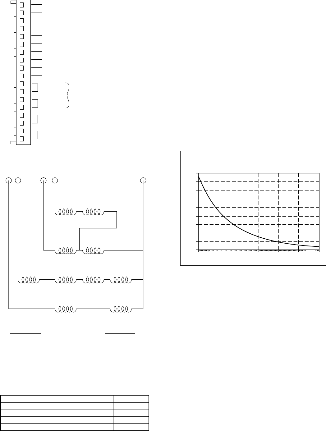
pressures exceeds 500 psi. The compressor is also protected by 3
PTC devices attached to the motor windings. The PTC’s resistance
is sensed by the 2-speed control board. See Table 16 for resistance
ranges.
MECHANICALLY INTERLOCKED CONTACTORS
The 2-speed products are equipped with mechanically interlocked
contactors. Each contactor has interconnecting linkage, providing
independent interlocks.
The 2-speed control provides the electrical interlock. The contac-
tors are supplied with 240v coils, which reduce the va require-
ments of the low-voltage (24vac) control system.
TEMPERATURE THERMISTORS
Thermistors are electronic devices which sense temperature. As
the temperature increases, the resistance decreases. Two ther-
mistors are used to sense temperature: one senses outdoor ambient,
and the other senses coil temperature (heat pump only). Refer to
Fig. 39 for resistance values versus temperature.
If the outdoor ambient thermistor should fail, a malfunction signal
appears on the indoor thermostat and 2-speed control. The control
does not initiate second-stage latching, crankcase heater is turned
on during all off-cycles, heating defaults to high speed, and defrost
initiates on demand from coil thermistor. (See Table 17.)
If the outdoor coil thermistor should fail, a malfunction signal
appears on the indoor thermostat and 2-speed control. The control
defrosts every 90 minutes of heating operation and terminates in 5
minutes. (See Table 17.)
V. LED FUNCTION/MALFUNCTION LIGHTS
The 2-speed control is equipped with an LED function/ malfunc-
tion light.
NOTE: Only malfunction signal appears at thermostat. Both
function and malfunction signals appear at control board. (See Fig.
33 for LED location.) Table 15 provides the function/malfunction
code, location, and definition.
VI. TROUBLESHOOTING
NOTE: Troubleshooting charts for air conditioning and heat
pump units are provided in the back of this manual —see Fig. 52,
53, and 54.
COMPRESSOR WINDING CHECK
The 2-speed compressor is nothing more than 2 single-phase
motors within 1 compressor shell. When the compressor fails to
start or run, there are 3 tests that can be made: open, ground, or
short. This compressor has no internal line-break overload; how-
ever, it does have PTC motor protectors. See Compressor PTC-
Overload Protection section for PTC overload information.
Fig. 37—Header-Pin Housing
A93576
1
2
3
4
5
6
7
8
9
10
11
12
13
14
15
16
17
18
JUMPER FOR
HEAT PUMP ONLY
C - TRANSFORMER COMMON
R - TRANSFORMER LINE
W2 - FIRST STAGE AUXILIARY HEAT
O - REVERSING VALVE
Y2 - SECOND STAGE COOLING/HEAT PUMP
L - MALFUNCTION LIGHT
Y1 - FIRST STAGE COOLING/HEAT PUMP
W3 - SECOND STAGE AUXILIARY HEAT
4 - TON
5 - TON
IF NO JUMPER IS
INSTALLED, DEFAULT
IS 3 - TON
Fig. 38—Energizing Windings
A92015
T3 T8 T7 T2 T1
EXTERNAL MAIN
MAIN WINDING
4 POLE START
2 POLE START
LOW SPEED
(L1) T1
(L2) T7 + T8
HIGH SPEED
(L1) T1 + T7
(L2) T2 + T3
TABLE 18—TWO-SPEED COMPRESSOR
(WINDING RESISTANCE AT 70°F±2°)
WINDING 3 TON 4 TON 5 TON
T1-T2 0.80 0.70 0.60
T1-T3 3.20 2.20 1.80
T1-T7 1.30 1.00 1.00
T1-T8 3.10 2.20 2.00
Fig. 39—Resistance Values Versus Temperature
A91431
0
10
20
30
40
50
60
70
80
90
0 20 40 60 80 100 120
TEMPERATURE (DEG. F)
RESISTANCE (KOHMS)
THERMISTOR CURVE
—34—
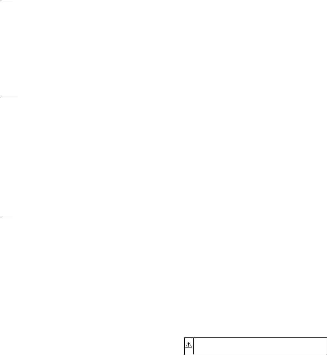
NOTE: To ensure accurate ohm measurements, place ohmmeter
probes on flat surface of compressor-terminal tabs, not the brass
mounting screw.
Open
To determine if a winding has an actual break in the internal wires
and current is unable to pass through:
1. Be sure all power is off.
2. Discharge all capacitors.
3. Remove wires from terminals T1, T2, T3, T7, and T8.
4. Use an ohmmeter on 0-1000 ohm scale to check resistance.
(See Fig. 38, 40, and 41 and Table 18.)
Because winding resistances are usually less than 10 ohm, each
reading will appear to be approximately zero ohm. If during any
check the resistance remains at 1000 ohm, an open or break exists,
and the motor or compressor should be replaced.
Ground
To determine if any wire has broken and come in direct contact
with the housing or shell, causing a direct short to ground:
1. Be sure all power is off.
2. Discharge all capacitors.
3. Remove wires from T1, T2, T3, T7, and T8.
4. Allow crankcase heater to remain on for several hrs before
checking motor to ensure that windings are not saturated
with refrigerant.
5. Using an ohmmeter on R X 10,000 ohm scale, place 1 meter
probe on ″ground″motor or compressor frame. Make a
good metal-to-metal contact. Place other probe on terminals
T1, T2, T3, T7, and T8 in sequence. Note meter scale.
If any reading of zero or low resistance is obtained, the motor is
grounding. Replace the compressor.
Short
NOTE: This is an extremely critical test and is not advised unless
the following conditions are met.
The correct motor-winding resistances must be known before
testing. See Table 18 for cold-motor winding resistance.
The temperature of the windings must be specified, 70°F±2°F.
The resistance-measuring instrument must have an accurate ohm-
meter (such as a Wheatstone bridge or null balance-type instru-
ment).
The motor must be dry or free from direct contact with liquid
refrigerant.
To determine if any wires have broken through their insulation and
come in direct contact with each other, thereby ″shorting″all or
part of the winding(s):
1. Be sure all power is off.
2. Discharge all capacitors.
3. Remove wires from terminals T1, T2, T3, T7, and T8.
4. Subtract instrument probe and lead resistance from each
reading. If any reading is within ± 20 percent of the known
resistance from Table 18, the motor probably does not have
a short. Usually a considerable difference will be noted if a
turn-to-turn short is present.
CONTROL BOARD FAILURE
The control board continuously monitors its own operation and the
operation of the system. The diagnostic feature allows easy
troubleshooting of the control and system in the field. If a failure
occurs, the LED light on the control will flash a failure code. If the
failure is internal to the control board, the light will stay on
continuously (no flash). Before replacing control board, reset the
24v power. If the fault clears, check to ensure the indoor and
outdoor unit and electrical service are properly grounded. If the
entire system is grounded, the control board should be replaced, as
the control is not field reparable. If the control-board light is
flashing, see LED and Table 15 for function/malfunction defini-
tion. Cycling 24 vac to control board resets previous error
messages and any lockouts which have occurred. See Table 19 for
more information regarding control-board operation.
CONTROL-BOARD POWER INPUTS AND OUTPUTS
See Fig. 33 and 37 for inputs and outputs.
BLEED RESISTOR
The bleed resistor is a 150k, 2–watt resistor across the compressor-
run capacitor to protect service technician from injury by electrical
shock. Capacitor will bleed-off approximately 1 minute after
power to outdoor unit is turned off. If run capacitor is changed out,
be sure to place bleed resistor on new capacitor. If bleed resistor is
damaged, replace resistor.
START CAPACITOR AND RELAY
The 2-speed system has a second start relay in the control box. One
start relay is for low-speed start, and the second is for high-speed
start. Both start relays use a common-start capacitor. When
servicing this equipment, be certain system starts in both low- and
high-speed operation.
REFRIGERATION SYSTEM
I. REFRIGERATION CYCLE
In a refrigeration system, refrigerant moves heat from one place to
another. It is useful to understand flow of refrigerant in a system.
In a straight cooling system, compressed hot gas leaves compres-
sor and enters condensing coil. As gas passes through condenser
coil, it rejects heat and condenses into liquid. The liquid leaves
condensing unit through liquid line and enters metering device at
indoor coil. As it passes through metering device, it becomes a
gas-liquid mixture. As it passes through indoor coil, it absorbs heat
and refrigerant and is again compressed to a hot gas. The cycle
then repeats.
In a heat pump, the basic cycle is the same. (See Fig. 42.)
Reversing valve in system decides which coil, indoor or outdoor,
becomes evaporator or condenser. It rejects heat into the home
after heat is absorbed by outdoor evaporator coil, thus the home is
heated.
In cooling cycle, the indoor coil becomes the evaporator. It absorbs
heat from the home and rejects it through the outdoor condenser
coil, thus the home is cooled.
A unique feature of the heat pump is that metering devices are
designed to meter refrigerant in one direction of flow and allow
refrigerant to pass unhindered in the other direction. If indoor-
metering device is metering refrigerant, the outdoor device by-
passes refrigerant and vice versa. This allows both coils to serve a
dual function.
II. LEAK DETECTION
CAUTION: Always wear safety glasses and gloves
when handling refrigerants.
New installations should be checked for leaks prior to complete
charging.
If a system has lost all or most of its charge, system must be
pressurized again, up to approximately 150 lb minimum. This can
be done by adding refrigerant using normal charging procedures,
or it may be pressurized with nitrogen (less expensive than
refrigerant). Nitrogen also leaks faster than R-22 and is not
absorbed by refrigeration oil. Nitrogen cannot, however, be
detected by a leak detector. (See Fig. 43.)
—35—
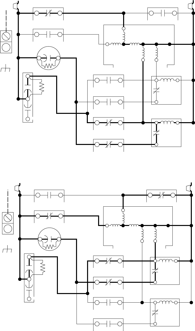
Fig. 40—Low-Speed Windings
A91446
EQUIP
GND
SC
17 27
EXT
MAIN
11 21
C1
L1
BR
CAP
H
LOW
START
MAIN
T2
T7 COMP
T1
HIGH
START
T3T8
25
1
HS
SR
2515
C2
2616
C2
2212
C1
2313
C1
C
F
C2
1424
C2
L2
LS
SR
25
1
SCHEMATIC DIAGRAM
(LADDER FORM)
Fig. 41—High-Speed Windings
A91445
EQUIP
GND
SC
17 27
EXT
MAIN
11 21
C1
L1
BR
CAP
H
LOW
START
MAINT2
T7 COMP
T1
HIGH
START
T3T8
25
1
HS
SR
2515
C2
2616
C2
2212
C1
2313
C1
C
F
C2
1424
C2
L2
LS
SR
25
1
SCHEMATIC DIAGRAM
(LADDER FORM)
—36—
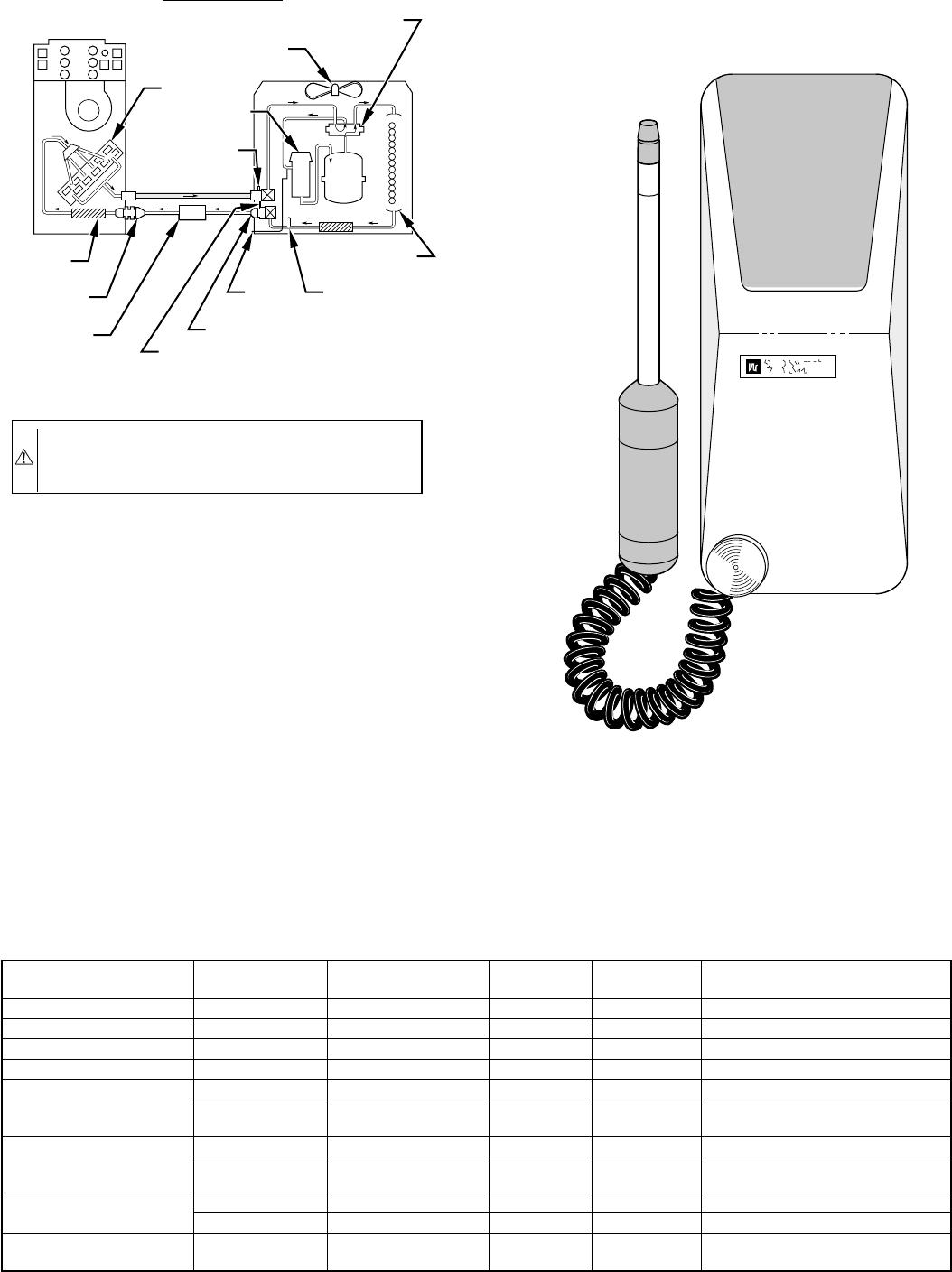
CAUTION: Due to the high pressure of nitrogen, it
should never be used without a pressure regulator on the
tank.
Leaks in a system pressurized with refrigerant can be spotted with
a leak detector that detects extremely small refrigerant leaks. This
discussion assumes that system is pressurized with either all
refrigerant or a mixture of nitrogen and refrigerant.
If system has been operating for some time, make first check for
a leak visually. Since refrigerant carries a small quantity of oil,
traces of oil at any joint or connection are an indication that
refrigerant is leaking at that point.
A simple and inexpensive method of testing for leaks is to use soap
bubbles. Any solution of water and soap may be used. Soap
solution is applied to all joints and connections in system. A small
pinhole leak is located by tracing bubbles in soap solution around
leak.
Use electronic leak detector to check for leaks. This unquestion-
ably is the most efficient and easiest method for checking leaks.
There are various types of electronic leak detectors. Generally
speaking, they are all portable, and most are lightweight, consist-
ing of a box with several switches and a probe or sniffer. Detector
is turned on and probe is passed around all fittings and connections
in system. Leak is detected by either a movement of a pointer on
detector dial, by a buzzing sound, or a light.
In all instances, when a leak is found, system charge must be bled
down and leak repaired before final charging and operation. After
leak testing or leak is repaired, evacuate system, and recharge with
correct refrigerant charge.
III. BRAZING
When brazing is required in the refrigeration system, certain basics
should be followed:
1. Clean joints make the best joints. To clean:
a. Remove all oxidation from surfaces to a shiny finish
before brazing.
TABLE 19—24V PIN CONNECTION TROUBLESHOOTING
MODE OF OPERATION
18-PIN CONNECTOR TERMINAL
DESIGNATION LOCATION ON
CONTROL BOARD VOLTAGE
PATH VOLTAGE
REQUIRED POSSIBLE SOURCE
OF PROBLEM
All R-C 2-1 Input 24 Check transformer (secondary)
Low-speed Cooling Y1,0-C 8,6-1 Input 24 Check thermostat
High-speed Cooling Y1, Y2, 0-C 8,7,6-1 Input 24 Check thermostat
Low-speed Heating Y1-C 8-1 Input 24 Check thermostat
High-speed Heating
Y1-C 8-1 Input 24 Check thermostat
Y2-C 7-1 Output 24 Outdoor temperature below
speed; change temperature
Defrost
Y1-C 8-1 Input 24 Check thermostat
Y2, W2, 0-C 7,5,6-1 Output 24 Outdoor temperature below 50°F;
Coil temperature less than 30°F
Second Stage of
Auxiliary Heat
Y1, W2-C 7,5-1 Input 24 Check thermostat
W3, Y2-C 9,8-1 Output 24 Check balance-point setting
Cooling Second-
stage Latching Y1, Y2, 0-C 8,7,6-1 Input 24 Ambient thermistor failure;
Check second-stage POT
Fig. 42—Heat Pump Refrigerant-Flow Diagrams
A88400
COOLING CYCLE
INDOOR COIL
OUTDOOR FAN
REVERSING VALVE
(ENERGIZED)
ACCUMULATOR
OUTDOOR
COIL
LIQUID LINE
PRESSURE SWITCH
(BYPASSING)
COMP
STRAINER
STRAINER
SUCTION
SERVICE
PORT
SUCTION SERVICE
PORT AT SERVICE
VALVE (CLG CYCLE)
(METERING)
INDOOR
FAN
LIQUID LINE SERVICE PORT
AT SERVICE VALVE (CLG CYCLE)
HEAT PUMP
ACCESSORY
FILTER DRIER
(DUAL FLOW)
Fig. 43—Leak Detector
A88401
—37—
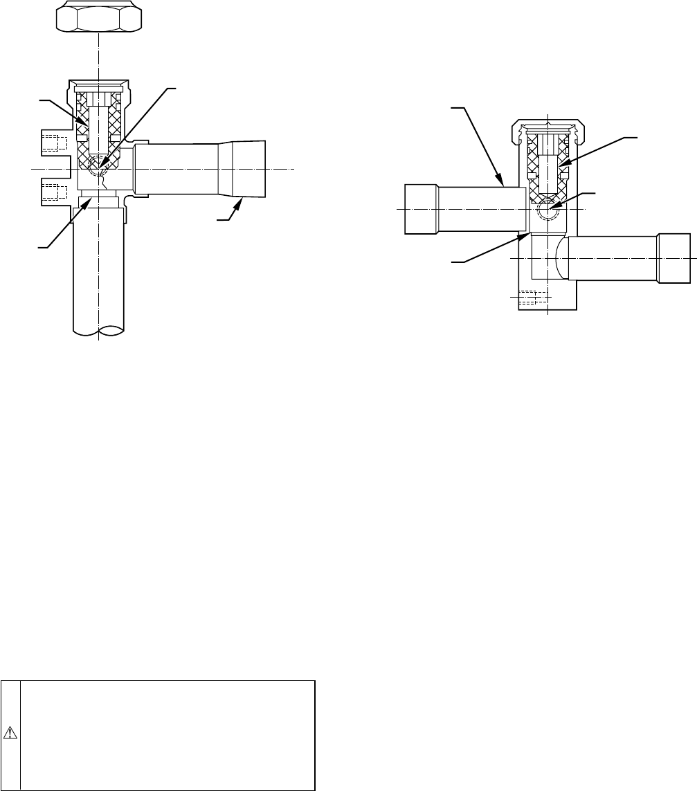
b. Remove all flux residue with brush and water while
material is still hot.
2. Use ″sil-fos″or ″phos-copper″for copper-to-copper only.
No flux is required.
3. Silver solder is used on copper-to-brass, copper-to-steel, or
copper-to-copper. Flux is required when using silver solder.
4. Fluxes should be used carefully. Avoid excessive applica-
tion and do not allow fluxes to enter into the system.
5. Proper brazing temperature of copper is when it is heated to
a dull red color.
This section on brazing is not intended to teach a technician how
to braze. There are books and classes that teach and refine brazing
techniques. The basic points above are listed only as a reminder.
IV. SERVICE VALVES
WARNING: Never attempt to make repairs to existing
service valves. Unit operates under high pressure. Dam-
aged seats and o-rings should not be replaced. Replace-
ment of entire service valve is required. Tampering with
damaged valves can cause personal injury or death.
Service valve must be replaced by properly trained
service technician.
Service valves provide a means for holding original factory charge
in outdoor unit prior to hookup to indoor coil. They also contain
gage ports for measuring system pressures and provide shutoff
convenience for certain types of repairs. (See Fig. 44.)
Two types of service valves are used in outdoor residential
equipment. The first type is a front-seating valve, which has a
service port that contains a Schrader fitting. The service port is
always pressurized after the valve is moved off the front-seat
position.
The second type is a combination front-seating/back-seating valve,
which has a metal-to-metal seat in both the open and closed
positions. When it is fully back-seated, the service port is not
pressurized. To pressurize the service port, this valve must be
moved off the back-seating position. This valve does not contain a
Schrader fitting. Both types of service valves are designed for
sweat connection to the field tubing.
The service valves in the outdoor unit come from the factory
front-seated. This means that the refrigerant charge is isolated from
the line-set connection ports. Some heat pumps are shipped with
sweat-adapter tube. This tube must be installed on the liquid-
service valve. After connecting the sweat adapter to the liquid-
service valve of a heat pump, the valves are ready for brazing. The
interconnecting tubing (line set) can be brazed to the service valves
using either silver-bearing or non-silver-bearing brazing material.
Consult local codes.
Before brazing the line set to the valves, the belled ends of the
sweat connections on the service valves must be cleaned so that no
brass plating remains on either the inside or outside of the bell
joint. To prevent damage to the valve and/or cap ″O″ring, use a
wet cloth or other acceptable heat-sinking material on the valve
before brazing. To prevent damage to the unit, use a metal barrier
between brazing area and unit.
After the brazing operation and the refrigerant tubing and evapo-
rator coil have been evacuated, the valve stem can be turned
counterclockwise until it opens or back-seats, which releases
refrigerant into tubing and evaporator coil. The system can now be
operated.
Back-seating service valves must be back-seated (turned counter-
clockwise until seated) before the service-port caps can be re-
moved and hoses of gage manifold connected. In this position,
refrigerant has access from and through outdoor and indoor unit.
The service valve-stem cap is tightened to 20 ± 2 ft/lb torque and
the service-port caps to9±2ft/lb torque. The seating surface of
the valve stem has a knife-set edge against which the caps are
tightened to attain a metal-to-metal seal. If accessory pressure
switches are used, the service valve must be cracked. Then, the
knife-set stem cap becomes the primary seal.
The service valve cannot be field-repaired; therefore, only a
complete valve or valve stem and service-port caps are available
for replacement.
FIELD
SIDE
SERVICE PORT
W/SCHRADER
CORE
SEAT
STEM
FORGED FRONT SEATING VALVE
A91448
STEM
SERVICE PORT
W/SCHRADER CORE
SEAT
BAR STOCK FRONT SEATING VALVE
FIELD
SIDE
A91447
Fig. 44—Service Valves
—38—
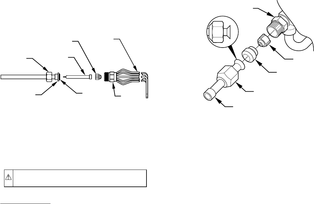
If the service valve is to be replaced, a metal barrier must be
inserted between the valve and the unit to prevent damaging the
unit exterior from the heat of the brazing operations.
CAUTION: Wear safety glasses and gloves when han-
dling refrigerants.
Pumpdown Procedure
Service valves provide a convenient shutoff valve useful for
certain refrigeration-system repairs. System may be pumped down
to make repairs on low side without losing complete refrigerant
charge.
1. Attach pressure gage to suction service-valve gage port.
2. Front seat liquid-line valve.
3. Start unit in cooling mode. Run until suction pressure
reaches 5 psig (35kPa). Do not allow compressor to pump
to a vacuum.
4. Shut unit off. Front seat suction valve.
NOTE: All outdoor unit coils will hold only factory-supplied
amount of refrigerant. Excess refrigerant, such as in long-line
applications, may cause unit to relieve pressure through internal
pressure-relief valve (indicated by sudden rise of suction pressure)
before suction pressure reaches 5 psig (35kPa). If this occurs, shut
off unit immediately, front seat suction valve, and recover remain-
ing pressure.
V. CHECK-FLO-RATER™(BYPASS-TYPE) HEAT
PUMPS ONLY REFRIGERANT-METERING HOLE
THROUGH IT. THE RETAINER FORMS A STOP FOR
PISTON IN REFRIGERANT-BYPASS MODE AND A SEAL-
ING SURFACE FOR LIQUID-LINE FLARE CONNECTION.
(SEE FIG. 45.) TO CHECK, CLEAN, OR REPLACE PIS-
TON:
RELIANT PRODUCTS EXCEPT 1992 PRODUCTION
1. Shut off power to unit.
2. Pump unit down using pumpdown procedure described in
this service manual.
3. Loosen nut and remove liquid-line flare connection from
Check-Flo-Rater™.
4. Pull retainer out of body, being careful not to scratch
flare-sealing surface. If retainer does not pull out easily,
carefully use locking pliers to remove it.
5. Slide piston out by inserting a small, soft wire with small
kinks through metering hole. Do not damage metering hole,
sealing surface around piston cones, or fluted portion of
piston.
6. Clean piston refrigerant-metering hole.
7. Install a new retainer O-ring or retainer assembly before
reassembling bypass-type Check-Flo-Rater™.
RELIANT AND CUBE PRODUCTS PRODUCED IN 1992
1. Shut off power to unit.
2. Reclaim outdoor-unit refrigerant.
3. Loosen brass hex nut and remove line from brass hex body.
4. Slide piston out by inserting a small, soft wire with small
kinks through metering hole. Do not damage metering hole,
sealing surface around piston cones, or fluted portion of
piston.
5. Clean piston refrigerant-metering hole.
6. Always replace Teflon seal with new seal. Never try to
reuse old seals.
7. Reassemble brass nut and brass hex body. Be sure orienta-
tion is as shown in Fig. 45.
VI. REVERSING VALVE
In heat pumps, changeover between heating and cooling modes is
accomplished with a valve that reverses flow of refrigerant in
system. (See Fig. 46.) This reversing-valve device is easy to
troubleshoot and replace. The reversing-valve solenoid can be
checked with power off with an ohmmeter. Check for continuity
and shorting to ground. With control-circuit (24v) power on, check
for correct voltage at solenoid coil. Check for overheated solenoid.
With unit operating, other items can be checked, such as frost or
condensate water on refrigerant lines.
The sound made by a reversing valve as it begins or ends defrost
isa″whooshing″sound, as the valve reverses and pressures in
system equalize. An experienced service technician detects this
sound and uses it as a valuable troubleshooting tool.
Using a remote measuring device, check inlet and outlet line
temperatures. DO NOT touch lines. If reversing valve is operating
normally, inlet and outlet temperatures on appropriate lines should
be close. Any difference would be due to heat loss or gain across
valve body. Temperatures are best checked with a remote-reading,
electronic-type thermometer with multiple probes. Route thermo-
couple leads to inside of coil area through service-valve mounting-
plate area underneath coil. Fig. 47 and 48 show test points (TP) on
reversing valve for recording temperatures. Insulate points for
more accurate reading.
BRASS
HEX
BODY
TEFLON
SEAL
PISTON
RETAINER
BRASS
HEX NUT STRAINER
PISTON
(ORIENT AS SHOWN)
FEEDER
TUBES
A91138
PISTON BODY
PISTON
PISTON RETAINER
INTERNAL STRAINER
FLARE ADAPTER
PRODUCTION
EXCEPT 1992
A94004
Fig. 45—Check-Flo-Rater™Components
—39—
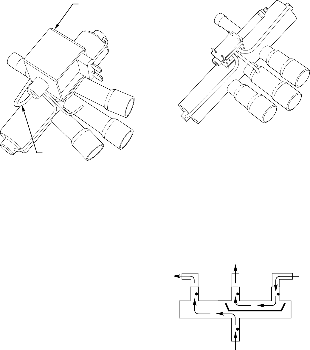
If valve is defective:
1. Shut off all power to unit and remove all charge from
system.
2. Check valve design. If valve is of the 3-port design and new
replacement is of the 4-port design, replacement of the
solenoid coil and wire leads is necessary. Valve bodies are
interchangeable, but solenoid and wires are not. Three-port
reversing valve and solenoid coil with leads must be used
together. New solenoid coil cannot be used on a 3-port
valve.
Four-port reversing valve uses solenoid with quick-connect
terminals for leads connection. Old solenoid coil cannot be
used on 4-port reversing valve. If for any reason a new wire
cord is not available, cut the leads on the old solenoid coil
as close to the coil as possible. Terminate the leads with 2
female 1/4-in. quick-connects. Connect terminals to new
solenoid and tape connection to insulate and provide
moisture barrier. Replace these wires as soon as wire cord
is available. See RCD (Replacement Component Catalog)
for proper cord part number.
3. Remove solenoid coil from valve body. Remove valve by
cutting it from system with tubing cutter. Repair person
should cut in such a way that stubs can be easily rebrazed
back into system. Do not use hacksaw. This introduces
chips into system that cause failure. After defective valve is
removed, wrap it in wet rag and carefully unbraze stubs.
Save stubs for future use. Because defective valve is not
overheated, it can be analyzed for cause of failure when it
is returned.
4. Braze new valve onto used stubs. Keep stubs oriented
correctly. Scratch corresponding matching marks on old
valve and stubs and on new valve body to aid in lining up
new valve properly. When brazing stubs into valve, protect
valve body with wet rag to prevent overheating.
5. Use slip couplings to install new valve with stubs back into
system. Even if stubs are long, wrap valve with a wet rag to
prevent overheating.
6. After valve is brazed in, check for leaks. Evacuate and
charge system. Operate system in both modes several times
to be sure valve functions properly.
VII. THERMOSTATIC-EXPANSION VALVES (TXV)
The types of TXVs used in condensing-unit and heat-pump
systems are as follows:
Rapid-Pressure Balance (RPB)—Has a special bleed port that
allows rapid bleed-through of pressure after system shutdown until
pressure equalization occurs within approximately 1 to 2 minutes.
NEW SOLENOID COIL
4TH PORT
4 PORT DESIGN
A91456
3 PORT DESIGN
A91457
Fig. 46—Reversing Valve
Fig. 47—Reversing Valve (Cooling Mode or Defrost
Mode, Solenoid Energized)
A88342
FROM INDOOR COIL VIA
SERVICE VALVE ON
OUTDOOR COIL
TO
ACCUMULATOR
TO OUTDOOR
COIL
TP-4 TP-3 TP-2
TP-1
FROM COMPRESSOR
DISCHARGE LINE
—40—
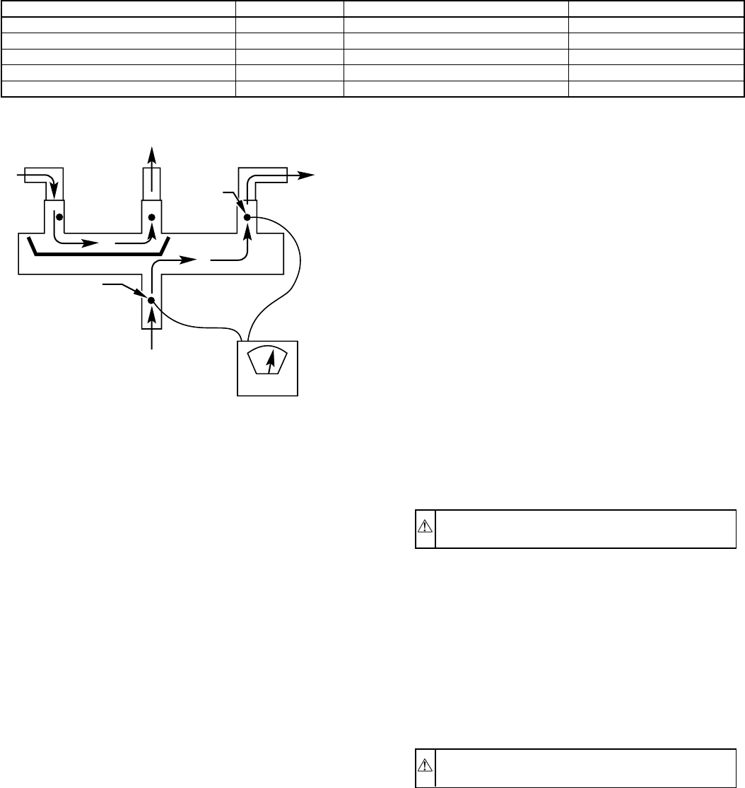
Hard Shutoff (HSO)—Has no bleed port and allows no bleed-
through after system shutdown. No pressure equalization occurs.
Because of unequalized system pressures, a start capacitor and
relay must be installed on single-phase reciprocating compressors
to start the compressor.
See Table 20 for TXV superheat settings. These settings are
factory set and are not field adjustable. Table 17 settings are for
Bryant-approved accessories and factory-installed TXVs only.
VIII. THERMOSTATIC-EXPANSION VALVE (BI-FLOW
TXV)
The standard TXV is a metering device that is used in condensing
and heat pump systems to adjust to changing load conditions by
maintaining a preset superheat temperature at the outlet of the
evaporator coil. The volume of refrigerant metered through the
valve seat is dependent upon:
1. Superheat temperature sensed by cap-tube sensing bulb on
suction tube at outlet of evaporator coil. As long as this bulb
and cap tube contains some liquid refrigerant, this tempera-
ture is converted into suction pressure pushing downward
on the diaphragm, which tends to open the valve via the
pushrods.
2. The suction pressure at the outlet of the evaporator coil is
transferred via the external equalizer tube to the underside
of the diaphragm.
3. The needle valve on the pin Bryant is spring-loaded, which
also exerts pressure on the underside of the diaphragm via
the pushrods, which tends to close the valve. Therefore,
bulb pressure equals evaporator pressure (at outlet of coil)
plus spring pressure. If the load increases, the temperature
increases at the bulb, which increases the pressure on the
topside of the diaphragm, which pushes the pin Bryant
away from the seat, opening the valve and increasing the
flow of refrigerant. The increased refrigerant flow causes
increased leaving evaporator pressure, which is transferred
via the equalizer tube to the underside of the diaphragm.
This tends to cause the pin-Bryant spring pressure to close
the valve. The refrigerant flow is effectively stabilized to
the load demand with negligible change in superheat. The
bi-flow TXV is used on split-system heat pumps. In the
cooling mode, the TXV operates the same as the standard
TXV previously explained. (See Fig. 49.)
However, when the system is switched to the heating mode
of operation, the refrigerant flow is reversed. The bi-flow
TXV has an additional internal-check valve and external
tubing. (See Fig. 50.) These additions allow the refrigerant
to bypass the TXV when refrigerant flow is reversed with
only a 1- to 2-psig pressure drop through the device. When
the heat pump switches to the defrost mode, the refrigerant
flows through a completely open (unthrottled) TXV, and
the bulb senses the residual heat of the outlet tube of the coil
that had been operating in the heating mode (about 85°F
and 155 psig). This temporary, unthrottled valve decreases
the indoor-pressure drop, which in turn increases the
refrigerant-flow rate, decreases overall defrost time, and
enhances defrost efficiency.
IX. COIL REMOVAL
Coils on this family of units are easy to remove, if required for
compressor removal or replacement coil.
CAUTION: Wear safety glasses and gloves when han-
dling refrigerants.
To remove or replace coil:
1. Shut off all power to unit.
2. Remove and recover refrigerant from system through ser-
vice valves.
3. Remove top cover. (See Remove Top Cover section.)
4. Remove screws in base pan to coil grille.
5. Remove coil grille from unit.
6. Remove screws on corner-post (Reliant) service-valve
panel (Cube unit) holding coil-tube sheet.
CAUTION: Cut tubes to reduce the possibility of fire
and personal injury.
7. Use midget-tubing cutter to cut liquid and vapor lines at
both sides of coil. Cut in convenient location for easy
reassembly with copper-slip couplings.
8. Lift coil vertically from basepan. Place aside carefully.
9. Reverse procedure to reinstall coil.
X. LIQUID-LINE STRAINER (HEAT PUMPS ONLY)
The liquid-line strainer is upstream of the heating piston. The
strainer catches debris in the liquid line during heating mode. If it
becomes plugged, system operation and pressure become abnor-
mal, and the compressor may become hot and cycle off on the
overloads or pressure relief.
TABLE 20—TXV SUPERHEAT SETTING AT OUTLET OF EVAPORATOR COIL
INSTALLATION TXV TYPE PRODUCT USAGE SUPERHEAT SETTING
Field Accessory RPB/HSO Air Conditioner Indoor Unit 10°
Field Accessory RPB/HSO Heat Pump Indoor Unit 6°
Field Accessory/Factory-Installed HSO Indoor Fan Coil Unit 6°
Factory-Installed HSO 2-Speed Heat Pump Outdoor Unit 4°
Factory-Shipped/Field-Installed HSO 2-Speed Indoor Unit 4°
Fig. 48—Reversing Valve (Heating Mode, Solenoid De-
Energized)
A88341
TO INDOOR COIL
VIA SERVICE VALVE
ON OUTDOOR COIL
TO
ACCUMULATOR
INSULATE
FOR
ACCURATE
READING
FROM
OUTDOOR
COIL
TP-4 TP-3 TP-2
TP-1
INSULATE FOR
ACCURATE
READING
FROM COMPRESSOR
DISCHARGE LINE
ELECTRONIC
THERMOMETER
—41—
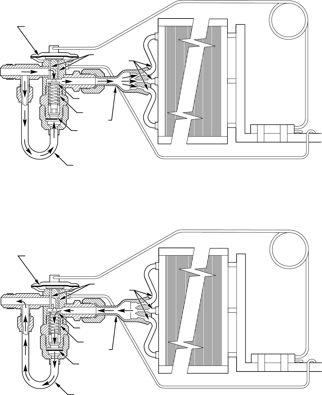
Fig. 49—TXV in Cooling Mode
A88406
OUTLET
INLET
PUSHRODS
BYPASS TXV
DIAPHRAGM
NEEDLE
VALVE
SPRING
CHECK VALVE
(CLOSED)
BYPASS TUBE
DISTRIBUTOR
FEEDER TUBES
CAPILLARY TUBE
COIL
BULB
EXTERNAL EQUALIZER TUBE
Fig. 50—TXV in Heating Mode
A88405
OUTLET
INLET
PUSHRODS
BYPASS TXV
DIAPHRAGM
NEEDLE
VALVE
SPRING
CHECK VALVE
(OPEN)
BYPASS TUBE
DISTRIBUTOR
FEEDER TUBES
CAPILLARY TUBE
COIL
BULB
EXTERNAL EQUALIZER TUBE
—42—
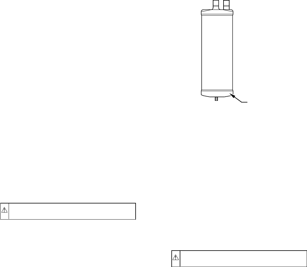
If the strainer must be replaced, shut off all power to the unit. See
Fig. 49 for strainer location.
XI. ACCUMULATOR
The accumulator is a device always found in heat pumps and found
in some condensing-unit models. Under some light-load condi-
tions on indoor coils and on outdoor coil with heat pump in heating
mode, some liquid refrigerant is present in suction gas returning to
compressor. The accumulator stores liquid and allows it to boil off
into a vapor so it can be safely returned to compressor. Since a
compressor is designed to pump refrigerant in its gaseous state,
introduction of liquid into it could cause severe damage or total
failure of compressor.
The accumulator is a passive device which seldom needs replac-
ing. Occasionally, its internal oil-return orifice or bleed hole may
become plugged. Some oil is contained in refrigerant returning to
compressor. It cannot boil off in accumulator with liquid refriger-
ant. The bleed hole allows a small amount of oil and refrigerant to
enter the return line where velocity of refrigerant returns it to
compressor. If bleed hole plugs, oil is trapped in accumulator, and
compressor will eventually fail from lack of lubrication. If bleed
hole is plugged, accumulator must be changed. Bleed hole is so
tiny that cleaning efforts are usually not successful. The accumu-
lator has a fusible element located in the bottom-end bell. (See Fig.
51.) This fusible element melts at 430°F and vents the refrigerant,
if this temperature is reached either internal or external to the
system. If fuse melts, the accumulator must be replaced.
To change accumulator:
1. Shut off all power to unit.
2. Remove and reclaim all refrigerant from system.
NOTE: Coil may be removed for access to accumulator. Refer to
appropriate sections of service manual for instructions.
CAUTION: Wear safety glasses and gloves when work-
ing on refrigerants and when using brazing torch.
3. When accumulator is exposed, remove it from system with
tubing cutter.
4. Scratch matching marks on tubing stubs and old accumu-
lator. Scratch matching marks on new accumulator. Un-
braze stubs from old accumulator and braze into new
accumulator.
5. Thoroughly rinse any flux residue from joints and paint
with corrosion-resistant coating such as zinc-rich paint.
6. Reinstall accumulator into system with copper-slip cou-
plings.
7. Evacuate and charge system.
8. Pour and measure oil quantity (if any) from old accumula-
tor. If more than 20 percent of oil charge is trapped in
accumulator, add oil to compressor to make up for this loss.
XII. CONTAMINANT REMOVAL
Proper evacuation of a unit removes non-condensibles and assures
a tight, dry system before charging. The 2 methods used to
evacuate a system are the deep-vacuum method and the triple-
evacuation method.
DEEP-VACUUM METHOD
The deep-vacuum method requires a vacuum pump capable of
pulling a vacuum of 1000 microns and a vacuum gage capable of
accurately measuring this vacuum depth. The deep-vacuum
method is the most positive way of assuring a system is free of air
and liquid water.
TRIPLE-EVACUATION METHOD
The triple-evacuation method can be used where the vacuum pump
is capable of pumping down to only 28 in. of mercury vacuum, and
the system does not contain any liquid water. The procedure is as
follows.
1. Pump the system down to 28 in. of mercury vacuum and
allow pump to continue to operate for additional 15
minutes.
2. Close service valves and shut off vacuum pump.
3. Connect a refrigerant cylinder to the system and open until
system pressure is 2 psig.
4. Close the service valve.
5. Allow system to stand for 1 hr, during which time the dry
refrigerant will be able to diffuse throughout the system,
absorbing moisture.
This procedure is repeated 3 times, after which the system will be
free of any contaminants and water vapor.
XIII. SYSTEM CHARGING
For all approved combinations, system must be charged correctly
for normal system operation and reliable operation of components.
CAUTION: Always wear safety glasses and gloves
when handling refrigerants.
If system has lost all charge, weigh in charge using dial-a-charge
or digital scale.
System charge should be fine-tuned by using the superheat or
subcooling method, whichever is appropriate. These methods are
covered in the Checking Charge section below.
NOTE: Heat-pump check charts are for checking charge and
performance and for adding a small amount of charge. During
heating mode, correct method of charging is the weight method. In
heating mode, check should be made approximately 15 minutes
after a defrost with unit running with a clean coil. In cooling cycle,
system should run at least 10 minutes for temperatures and
pressures to stabilize. All charts assume there are no system
abnormalities and indoor coil airflows are correct. If system
abnormalities exist, correct them before checking system charge.
XIV. CHECKING CHARGE
Superheat charging is the process of charging refrigerant into a
system until the temperature (superheat) of the suction gas entering
the compressor reaches a prescribed value. Small variations of
charge affect suction-gas superheat temperatures greatly. There-
fore, this method of charging is very accurate. This method can be
used only on split-system condensing units and heat pumps
(operating in the cooling mode) with fixed-restrictor-type metering
devices such as Check-Flo-Rater™, cap tube, etc. For units using
Fig. 51—Accumulator
A88410
430° FUSE
ELEMENT
—43—
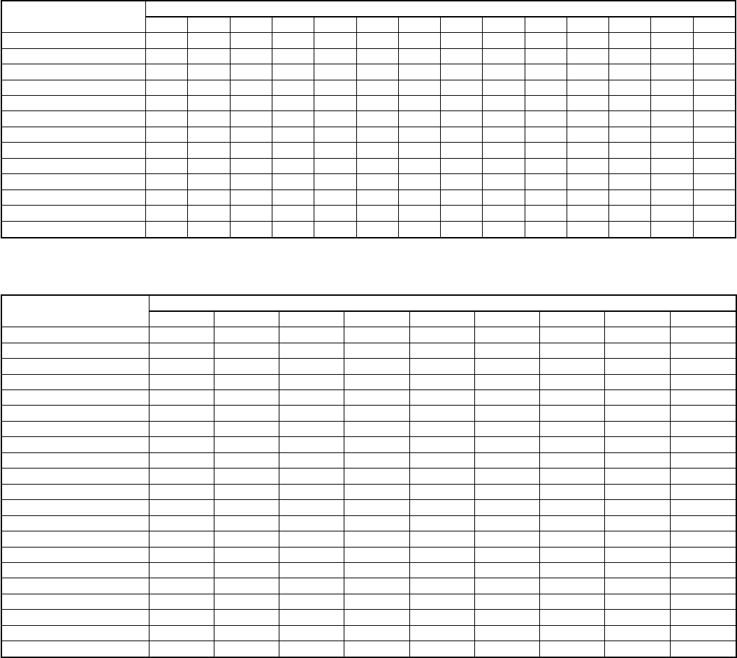
a TXV, the subcooling method must be used. Heat pumps must be
operating in the cooling mode. To charge by superheat, a service
technician needs an accurate superheat thermocouple or
thermistor-type thermometer, a sling psychrometer, and a gage
manifold. Do not use mercury or small-dial-type thermometers as
they are not adequate for this type of measurement. Then use 1 of
the following procedures:
SUPERHEAT CHARGING METHOD
1. Operate a unit a minimum of 10 minutes before checking
charge.
2. Measure vapor pressure by attaching a gage to vapor
valve-service port.
3. Measure vapor-line temperature by attaching a service
thermometer to unit vapor line near vapor valve. On a heat
pump, attach to the suction tube between the accumulator
and the compressor. Insulate thermometer for accurate
readings.
4. Measure outdoor-air, dry-bulb temperature with a second
thermometer.
5. Measure indoor-air (entering indoor coil), wet-bulb tem-
perature with a sling psychrometer.
6. Locate outdoor temperature and evaporator entering air
wet-bulb temperature in Table 21. At this intersection note
the superheat.
7. Locate superheat temperature located in previous step and
vapor pressure in Table 22. At this intersection note
vapor-line temperature.
8. If unit has a higher vapor-line temperature than charted
temperature, add refrigerant until charted temperature is
reached.
9. If unit has a lower vapor-line temperature than charted
temperature, bleed refrigerant until charted temperature is
reached.
10. If outdoor-air temperature or pressure at vapor valve
changes, charge to new vapor-line temperature indicated on
chart.
SUBCOOLING CHARGING METHOD
1. Operate unit a minimum of 15 minutes before checking
charge.
TABLE 21—SUPERHEAT CHARGING TABLE
OUTDOOR TEMP (°F) INDOOR COIL ENTERING AIR TEMP (°F WET BULB)
50 52 54 56 58 60 62 64 66 68 70 72 74 76
55 9 12141720232629323537404245
60 7 10121518212427303335384043
65 —6 101316192124273033363841
70 —— 7 1013161921242730333639
75 ——— 6 9 12 15 18 21 24 28 31 34 37
80 ———— 5 8 12 15 18 21 25 28 31 35
85 —————— 8 11151922263033
90 —————— 5 9 13 16 20 24 27 31
95 ——————— 6 101418222529
100 ———————— 8 1215202327
105 ———————— 5 9 13 17 22 26
110 ————————— 6 11152025
115 —————————— 8 141823
Where a dash appears, do not attempt to charge system under these conditions or refrigerant slugging may occur.
TABLE 22—REQUIRED VAPOR TEMPERATURE (°F)
SUPERHEAT TEMP
(°F) VAPOR PRESSURE AT SERVICE PORT (PSIG)
61.5 64.2 67.1 70.0 73.0 76.0 79.2 82.4 85.7
035 37 39 41 43 45 47 49 51
237 39 41 43 45 47 49 51 53
439 41 43 45 47 49 51 53 55
641 43 45 47 49 51 53 55 57
843 45 47 49 51 53 55 57 59
10 45 47 49 51 53 55 57 59 61
12 47 49 51 53 55 57 59 61 63
14 49 51 53 55 57 59 61 63 65
16 51 53 55 57 59 61 63 65 67
18 53 55 57 59 61 63 65 67 69
20 55 57 59 61 63 65 67 69 71
22 57 59 61 63 65 67 69 71 73
24 59 61 63 65 67 69 71 73 75
26 61 63 65 67 69 71 73 75 77
28 63 65 67 69 71 73 75 77 79
30 65 67 69 71 73 75 77 79 81
32 67 69 71 73 75 77 79 81 83
34 69 71 73 75 77 79 81 83 85
36 71 73 75 77 79 81 83 85 87
38 73 75 77 79 81 83 85 87 89
40 75 77 79 81 83 85 87 89 91
—44—
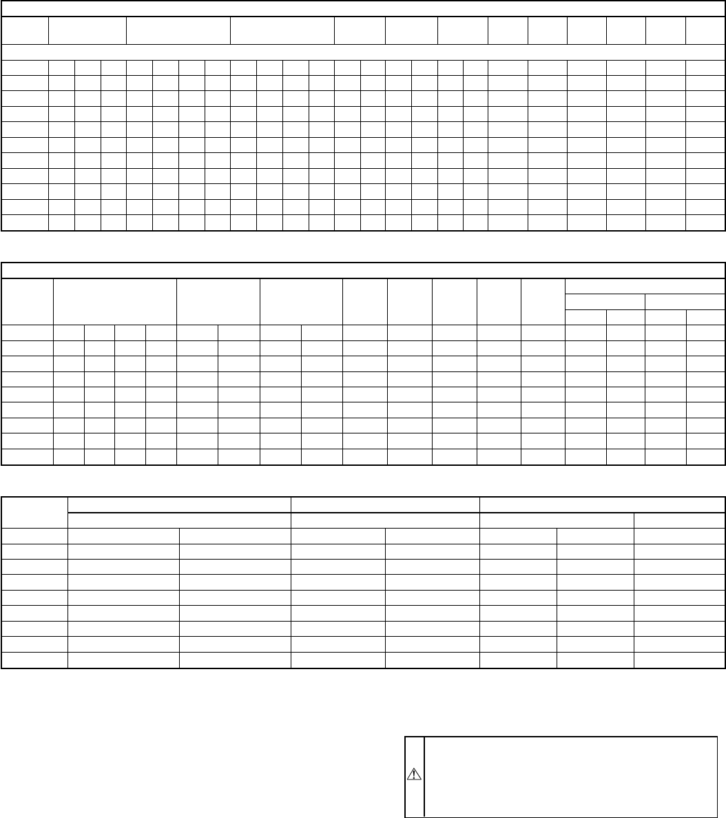
2. Measure liquid service-valve pressure by attaching an
accurate gage to the service port.
3. Measure the liquid-line temperature by attaching an accu-
rate thermistor-type or electronic thermometer to the liquid
line near the outdoor coil.
4. Refer to unit-rating plate to find required subcooling
temperature for units produced during or after January
1993. For units produced through December 1992, refer to
Table 23. Find the point at which the required subcooling
temperature intersects the measured liquid service-valve
pressure on Table 24.
5. To obtain the required subcooling temperature at a specific
liquid-line pressure, add refrigerant if liquid-line tempera-
ture is higher than indicated or remove refrigerant if
temperature is lower. Allow a tolerance of 3°F.
CARE AND MAINTENANCE
To assure high performance and minimize possible equipment
malfunction, it is essential that maintenance be performed periodi-
cally on this equipment. The frequency with which maintenance is
performed is dependent on such factors as hours of operation,
geographic location, and local environmental conditions.
WARNING: Disconnect all electrical power to unit
before performing any maintenance or service on outdoor
unit. Remember to disconnect power supply to air handler
as this unit supplies low-voltage power to the outdoor
unit. Electric shock can cause personal injury or death.
The minimum maintenance that should be performed on this
equipment is as follows.
1. Check outdoor coil for cleanliness each month during the
heating (heat pump only) or cooling season and clean as
necessary, but clean at least once each heating (heat pump
only) and cooling season.
2. Check fan motor and blade for cleanliness each heating and
cooling season and clean as necessary.
TABLE 23—SUBCOOLING AT LIQUID-SERVICE VALVE FOR UNITS PRODUCED THROUGH DECEMBER, 1992
RELIANT AIR CONDITIONERS
Model 590A 591A/592A 593A/594A 593B 593C 594C 595A 596A 597A 597B 598A
High 598A
Low
Series ABCABCDABCDABABABAAAAAA
014 14 14 —14 14 14 —66——————————————
018 17 17 —14 14 14 —77——11 —99—— 98————
024 13 13 —17 17 17 —88——13 —16 21 12 —13 12 11 13 ——
030 15 15 —91010—6 6 10 13 11 —15 15 14 —10 9 10 11 ——
036 13 12 —16 16 16 —12 12 5 —9—13 12 16 —14 13 12 14 12 9
038 ———————————16 ———————————
042 13 13 14 16 19 19 15 12 12 ——11 —13 —21 —11 11 15 15 ——
048 15 14 —18 14 18 —14 14 ——18 —17 —14 —10 10 11 11 12 9
060 19 22 —18 18 18 —14 14 ——11 —16 —19 —— — 12 11 12 9
RELIANT HEAT PUMPS
Model 690A 691A/692A 693A/694A 693B 693C 694C 697A 697B
698A
Cooling Heating
High Low High Low
Series ABCDABABA A A A AAAAA
014 777—————— — — — —————
018 18 18 18 —16 16 11 11 10 9 7 9 10 ————
024 18 18 18 —16 16 11 11 13 6 5 11 11 ————
030 13 13 13 —20 20 10 10 11 10 10 9 10 ————
036 18 18 18 —14 14 10 10 11 13 12 9 10 12 7 18 15
042 13 11 11 —18 18 15 15 12 10 12 11 12 ————
048 22 17 15 14 19 14 13 13 —15 12 10 11 14 9 25 18
060 23 23 23 —13 13 14 14 —15 10 12 7 14 9 22 21
MODEL CUBE UNIT—AIR CONDITIONERS CUBE UNIT—HEAT PUMPS HORIZONTAL AIR CONDITIONERS
561A/571A 661A/671A 566D 566E
Series ABABCDA
014 ————10 ——
018 15 16 11 14 12 —17
024 14 11 14 8 —— 19
030 12 12 9 10 —12 —
036 18 16 11 7 —— —
042 18 17 7 ————
048 —17 12 ————
060 —21 10 ———
—45—
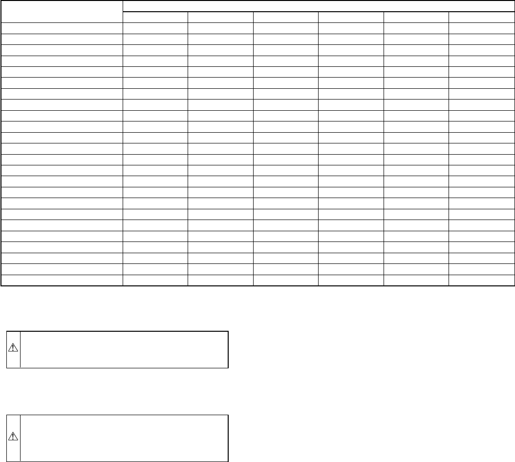
3. Check electrical connections for tightness and controls for
proper operation each heating (heat pump only) or cooling
season and service as necessary.
CAUTION: Because of possible damage to the equip-
ment or personal injury, maintenance should be per-
formed by qualified personnel only.
COIL CLEANING
1. Remove top cover. See Remove Top Cover section.
CAUTION: Coil fin damage can result in higher oper-
ating costs or compressor damage. Do not use flame,
high-pressure water, steam, or volatile or corrosive clean-
ers on fins or tubing.
2. Clean coil using vacuum cleaner and its crevice tool. Move
crevice tool vertically, close to area being cleaned, making
sure tool touches only the dirt on the fins and not the fins.
To prevent fin damage, do not scrub fins with tool or move
tool horizontally against fins.
3. If oil deposits are present, spray coil with ordinary house-
hold detergent. Wait 10 minutes, and proceed to next step.
4. Using garden hose, spray coil vertically downward with
constant stream of water at moderate pressure. Keep nozzle
ata15°to 20°angle, about 3 in. from coil face and 18 in.
from tube. Spray so debris is washed out of coil and
basepan.
5. Restore power to unit.
CLEANING OUTDOOR FAN MOTOR AND BLADE
1. Remove fan motor and blade. Refer to Remove Fan-Motor
Assembly section of this manual. Be careful not to bend or
dent fan blade.
2. Clean motor and blade with soft brush or cloth. Be careful
not to disturb balance weights on fan blade.
3. Check fan-blade setscrew for tightness.
4. Reinstall fan motor and blade to top cover and check for
alignment.
5. Reinstall top cover and position blade as per Fig. 24.
6. Reconnect electrical power and check for proper operation.
ELECTRICAL CONTROLS AND WIRING
1. Disconnect power to both the outdoor and indoor units.
2. Check all electrical connections for tightness. Tighten all
screws on electrical connections. If any connections appear
to be burned or smoky, disassemble the connection, clean
all parts and stripped wires, and reassemble. Use a new
connector if old one is burned or corroded and crimp
tightly.
3. Reconnect electrical power to the indoor and outdoor units
and observe unit through 1 complete operating cycle.
4. If there are any discrepancies in the operating cycle,
troubleshoot to find the cause, and correct.
REFRIGERANT CIRCUIT
1. Check the refrigerant charge using the superheat or sub-
cooling method, whichever is applicable. If low on charge,
check unit for leaks using an electronic leak detector.
2. If any leaks are found, recover or isolate charge (pump-
down) if applicable and make necessary repairs.
3. Evacuate, recharge, and operate unit through entire cycle.
FINAL CHECKOUT
After the unit has been operating, the following items should be
checked:
1. Check that unit operational noise is not excessive due to
vibration of components, tubing, panels, etc. If present,
isolate problem and correct.
2. Check to be sure caps are installed on service valves and
that they are tight.
TABLE 24—REQUIRED LIQUID-LINE TEMPERATURE
PRESSURE (PSIG)
AT SERVICE FITTING REQUIRED SUBCOOLING TEMPERATURE (°F)
0 5 10 15 20 25
134 76 71 66 61 56 51
141 79 74 69 64 59 54
148 82 77 72 67 62 57
156 85 80 75 70 65 60
163 88 83 78 73 68 63
171 91 86 81 76 71 66
179 94 89 84 79 74 69
187 97 92 87 82 77 72
196 100 95 90 85 80 75
205 103 98 93 88 83 78
214 106 101 96 91 86 81
223 109 104 99 94 89 84
233 112 107 102 97 92 87
243 115 110 105 100 95 90
253 118 113 108 103 98 93
264 121 116 111 106 101 96
274 124 119 114 109 104 99
285 127 122 117 112 107 102
297 130 125 120 115 110 105
309 133 128 123 118 113 108
321 136 131 126 121 116 111
331 139 134 129 124 119 114
346 142 137 132 127 122 117
359 145 140 135 130 125 120
—46—

3. Check to be sure tools, loose parts, and debris are removed
from the unit.
4. Check to be sure all panels and screws are in place and
tight.
Desert and Seacoast Locations
Special consideration must be given to the installation and main-
tenance of condensing units and heat pumps installed in seacoast
or desert locations. Salt and the alkali content of the sand adhere
to the aluminum fins of the coil and can cause premature coil
failure due to corrosion.
Preventive measures can be taken during installations, such as:
1. Locating the unit on side of structure opposite the prevailing
winds.
2. Elevating the unit to height where drifting sand cannot pile
up against coil. Four-in.-high mounting feet or an 18-in.-
high mounting rack are available as accessories and can be
used to elevate the unit.
3. Addition of coastal filter (see pre-sale literature for acces-
sory listing).
Special maintenance requirements are as follows:
1. Frequent inspection of coil and base pan, especially after
storms and/or high winds.
2. Cleaning coil by flushing out sand from between coil fins
and out of base pan as frequently as inspection determines
necessary.
3. Protecting the unit in ″off season″with cover that allows air
to circulate through but prevents sand from sifting in (such
as canvas material). Do not use plastic as plastic will hold
moisture.
—47—
Fig. 52—Air-Conditioner Troubleshooting Chart
A90208
AIR CONDITIONER
TROUBLESHOOTING CHART
NO COOLING OR
INSUFFICIENT
COOLING
COMPRESSOR
WILL NOT RUN
CONTACTOR
OPEN
POWER SUPPLY
DEFECTIVE
LOW-VOLTAGE
TRANSFORMER
OPEN
THERMOSTAT
OPEN CONTROL
CIRCUIT
LOSS OF
CHARGE
CONTACTOR OR
COIL DEFECTIVE
LOOSE
ELECTRICAL
CONNECTION
CONTACTOR
CLOSED
COMPRESSOR
POWER SUPPLY
OPEN
LOOSE LEADS AT
COMPRESSOR
FAULTY START
GEAR (1-PH)
OPEN SHORTED
OR GROUNDED
COMPRESSOR
MOTOR
WINDINGS
COMPRESSOR
STUCK
COMPRESSOR
INTERNAL
PROTECTION
OPEN
DEFECTIVE RUN
CAPACITOR
OUTDOOR FAN
STOPPED OR
CYCLING ON
OVERLOAD
OUTDOOR AIR
RESTRICTED OR
RECIRCULATING
RESTRICTED
DISCHARGE
TUBE
OVERCHARGE
OR NON-
CONDENSABLES
IN SYSTEM
LOW
REFRIGERANT
CHARGE
LINE VOLTAGE
TOO HIGH OR
LOW
DEFECTIVE RUN
CAPACITOR
COMPRESSOR
BEARINGS
HIGH
SUPERHEAT
LOOSE LEAD
AT FAN MOTOR
MOTOR
DEFECTIVE
LOW SUCTION
PRESSURE
DIRTY AIR
FILTERS
DUCT
RESTRICTED
DAMPERS
PARTLY CLOSED
COMPRESSOR
RUNS BUT
CYCLES ON
INTERNAL
OVERLOAD
COMPRESSOR
RUNS BUT
INSUFFICIENT
COOLING
INCORRECT
OFM
CAPACITOR
INDOOR COIL
FROSTED
SLIGHTLY
LOW ON
REFRIGERANT
LIQUID LINE
SLIGHTLY
RESTRICTED
PISTON
RESTRICTED
INCORRECT
SIZE
PISTON
INDOOR COIL
STRAINER
RESTRICTED
INDOOR
BLOWER MOTOR
DEFECTIVE OR
CYCLING ON OL
HIGH SUCTION
LOW HEAD
PRESSURE
DEFECTIVE
COMPRESSOR
VALVES
INTERNAL
PRESSURE
RELIEF OPEN
HIGH SUCTION
LOW
SUPERHEAT
UNIT
OVERCHARGED
INCORRECT
SIZE
PISTON
—48—
Fig. 53—Heat-Pump Troubleshooting Chart —Cooling Cycle
A90207
HEAT PUMP
TROUBLESHOOTING–COOLING CYCLE
NO COOLING OR
INSUFFICIENT
COOLING
COMPRESSOR
WILL NOT RUN
CONTACTOR
OPEN
POWER SUPPLY
DEFECTIVE
LOW-VOLTAGE
TRANSFORMER
OPEN
THERMOSTAT
OPEN CONTROL
CIRCUIT
LOSS OF
CHARGE
CONTACTOR OR
COIL DEFECTIVE
LOOSE
ELECTRICAL
CONNECTION
CONTACTOR
CLOSED
COMPRESSOR
POWER SUPPLY
OPEN
LOOSE LEADS AT
COMPRESSOR
FAULTY START
GEAR (1-PH)
OPEN SHORTED
OR GROUNDED
COMPRESSOR
MOTOR
WINDINGS
COMPRESSOR
STUCK
COMPRESSOR
INTERNAL
PROTECTION
OPEN
DEFECTIVE RUN
CAPACITOR
OUTDOOR FAN
STOPPED OR
CYCLING ON
OVERLOAD
OUTDOOR AIR
RESTRICTED OR
RECIRCULATING
DAMAGED OR
STUCK
REVERSING
VALVE
RESTRICTED
DISCHARGE
TUBE
OVERCHARGE
OR NON-
CONDENSABLES
IN SYSTEM
LOW
REFRIGERANT
CHARGE
LINE VOLTAGE
TOO HIGH OR
LOW
DEFECTIVE RUN
CAPACITOR
COMPRESSOR
BEARINGS
HIGH
SUPERHEAT
LOOSE LEAD
AT FAN MOTOR
DEFROST RELAY
N.C. CONTACTS
OPEN
MOTOR
DEFECTIVE
LOW SUCTION
PRESSURE
DIRTY AIR
FILTERS
DUCT
RESTRICTED
DAMPERS
PARTLY CLOSED
COMPRESSOR
RUNS BUT
CYCLES ON
INTERNAL
OVERLOAD
COMPRESSOR
RUNS BUT
INSUFFICIENT
COOLING
INCORRECT
OFM
CAPACITOR
DEFECTIVE
DEFROST
THERMOSTAT
INDOOR COIL
FROSTED
SLIGHTLY
LOW ON
REFRIGERANT
LIQUID LINE
SLIGHTLY
RESTRICTED
PISTON
RESTRICTED
INCORRECT
SIZE
PISTON
INDOOR COIL
STRAINER
RESTRICTED
INDOOR
BLOWER MOTOR
DEFECTIVE OR
CYCLING ON OL
HIGH SUCTION
LOW HEAD
PRESSURE
REVERSING
VALVE HUNG UP
OR INTERNAL
LEAK
DEFECTIVE
COMPRESSOR
VALVES
INTERNAL
PRESSURE
RELIEF OPEN
HIGH SUCTION
LOW
SUPERHEAT
UNIT
OVERCHARGED
INCORRECT
SIZE
PISTON
—49—
Fig. 54—Heat-Pump Troubleshooting Chart —Heating Cycle
A90206
HEAT PUMP
TROUBLESHOOTING–HEATING CYCLE
NO HEATING OR
INSUFFICIENT
HEATING
COMPRESSOR
WILL NOT RUN
CONTACT
OPEN
DEFECTIVE LOW-
VOLTAGE
TRANSFORMER
REMOTE
CONTROL
CENTER
DEFECTIVE
CONTACTOR
COIL OPEN OR
SHORTED
OPEN INDOOR
THERMOSTAT
LIQUID-LINE
PRESSURE
SWITCH OPEN
LOSS OF
CHARGE
OPEN CONTROL
CIRCUIT
CONTACTOR
CLOSED
COMPRESSOR
POWER SUPPLY
LOOSE LEADS AT
COMPRESSOR
FAULTY START
GEAR (1-PH)
COMPRESSOR
STUCK
COMPRESSOR
INTERNAL
OVERLOAD
OPEN
OPEN SHORTED
OR GROUNDED
COMPRESSOR
WINDINGS
DEFECTIVE RUN
CAPACITOR
DIRTY FILTERS
OR INDOOR
COIL
INDOOR FAN
STOPPED OR
CYCLING ON
OVERLOAD
DAMAGED
REVERSING
VALVE
RESTRICTION IN
DISCHARGE LINE
OVERCHARGE
OR NON-
CONDENSABLES
IN SYSTEM
LOW
REFRIGERANT
CHARGE
LINE VOLTAGE
TOO HIGH OR
LOW
DEFECTIVE RUN
CAPACITOR
(1-PH)
COMPRESSOR
BEARINGS
HIGH-LOAD
CONDITION
REVERSING
VALVE JAMMED
IN MIDPOSITION
HIGH
SUPERHEAT
DEFECTIVE FAN
MOTOR
CAPACITOR
LOOSE LEADS
AT
FAN MOTOR
FAN MOTOR
BURNED
OUT
LOW SUCTION
LOW HEAD
OUTDOOR FAN
STOPPED
LOOSE LEADS
AT OUTDOOR
FAN MOTOR
INTERNAL FAN
MOTOR KLIXON
OPEN
FAN MOTOR
BURNED OUT
DEFROST RELAY
N.C. CONTACTS
OPEN ON
CIRCUIT BOARD
REVERSING
VALVE DID NOT
SHIFT
UNIT NOT
PROPERLY
CHARGED
OUTDOOR FAN
RUNNING
REVERSING
VALVE STUCK
RESTRICTED
LIQUID LINE
PISTON
RESTRICTED OR
IS CLOGGED
UNDER-
CHARGED
OUTDOOR COIL
DIRTY
STRAINER
RESTRICTED
OUTDOOR COIL
HEAVILY
FROSTED
DEFECTIVE
DEFROST
THERMOSTAT
DEFROST
THERMOSTAT IN
POOR PHYSICAL
CONTACT WITH
TUBE
DEFECTIVE
CIRCUIT BOARD
BAD ELECTRICAL
CONNECTION
ANYWHERE IN
DEFROST
CIRCUIT
STRIP HEATERS
NOT OPERATING
OUTDOOR
THERMOSTAT
DEFECTIVE
ODT SETTING
TOO LOW
CAP TUBE
PINCHED OR
BULB NOT
SENSING TRUE
ODT
STRIP HEATER
RELAY OR
CONTACTOR
DEFECTIVE
OPENING IN
POWER CIRCUIT
TO HEATER
ELEMENTS
BROKEN FUSE
LINK
BROKEN
HEATER
ELEMENT
OPEN (KLIXON)
OVER
TEMPERATURE
THERMOSTAT
DEFECTIVE
ROOM
THERMOSTAT
(2ND STAGE)
COMPRESSOR
RUNS BUT
CYCLES ON
INTERNAL
OVERLOAD
COMPRESSOR
RUNS
INSUFFICIENT
HEATING
FAN MOTOR
CONTACTS
WELDED CLOSED
IN DEFROST
RELAY
—50—
—51—
© 2000 Bryant Heating & Cooling Systems 7310 W. Morris St. Indianapolis, IN 46231 —52—Printed in U.S.A. sm01,025 Catalog No. 5356-109
