Bryant Thermostat Q674 Users Manual 60 2485 T874 Multistage Thermostats And Subbases
T874 to the manual ad722da2-d369-4efc-b7c2-1152a01c2f4c
2015-02-02
: Bryant Bryant-Thermostat-Q674-Users-Manual-412150 bryant-thermostat-q674-users-manual-412150 bryant pdf
Open the PDF directly: View PDF ![]() .
.
Page Count: 224 [warning: Documents this large are best viewed by clicking the View PDF Link!]
- Application
- Features
- Specifications
- Installation
- Settings
- Checkout
- Calibration
- Understanding Circuits
- Operation
- Heat Anticipation/Cool Anticipation
- Interstage Differential
- Droop
- Outdoor Reset
- Service and Replacement of C815A Outdoor Thermistor
- Features
- Led Indicators
- Restricted Setpoint (DoD)
- Applications
- Changeover on Standard Residential Systems
- Commercial Rooftop Application
- Heat Pump Application
- Space Temperature Sensing Low Voltage Controls
- Two-Stage Thermostat
- Cycling Rate
- Voltage Anticipation
- Outdoor Reset
- Outdoor Reset—How it Works
- Changeover
- Low Temperature Lockouts
- Heat Pumps with Dual Compressors
- Two speed Heat Pump
- Defrost Control
- Defrosting
- Auxiliary Heat
- Two-Stage Thermostat
- Stage or Time Modulated Control
- Three-Stage Thermostat
- Emergency Heat
- Switching to Emergency Heat
- Crankcase Heat
- Compressor Fault Relay
- Cross Reference
- Wiring Diagrams
PRODUCT DATA
60- 248
5
-
8
® U.S. Re
g
istered Trademark
Cop
y
ri
g
ht © 2001 Hone
y
well • All Ri
g
hts Reserved
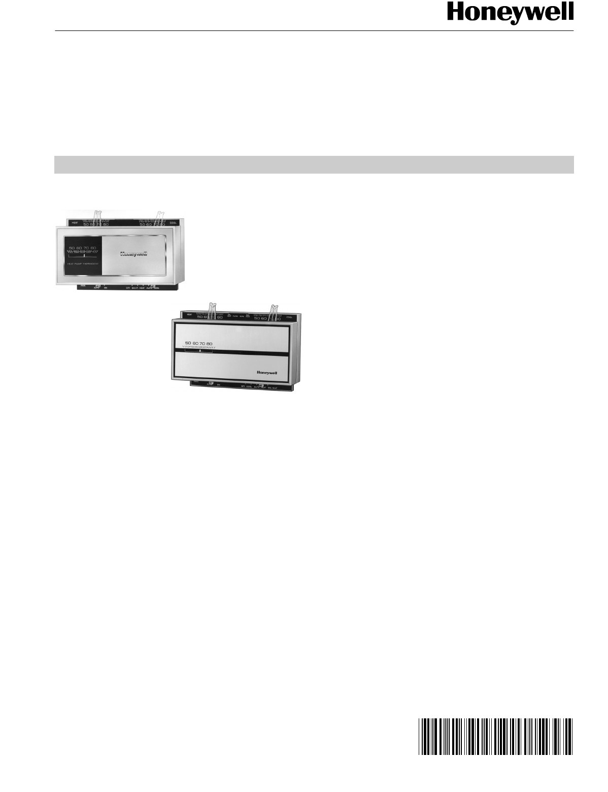
T874 Multistage Thermostats
and Q674 Subbases
APPLICATION
These thermostats and subbases provide low volta
g
e control
of multista
g
e heatin
g
and coolin
g
s
y
stems, includin
g
heat
pump s
y
stems.
FEATURES
• T874 Thermostat has silent, dust-free mercury
switches operated by coiled bimetal elements.
• Heat anticipator(s) are adjustable or fixed cooling
anticipator(s) are fixed.
• Individual heat and cool levers and scales (most
models) for temperature setting located on top of
thermostat case.
• Cover thermometer on most T874 Multistage
Thermostat models.
• Locking cover and locking lever screws available for
T874 Multistage Thermostats.
• Versaguard™ Thermostat Guard or custom key lock
thermostat guards available for T874 Multistage
Thermostats.
• T874 Thermostat requires a Q674 Subbase.
• Q674 Subbase provides system and fan switching,
wiring terminals and mounting base for T874
Multistage Thermostat.
• Adapter plate available for mounting Q674 on wall or
horizontal outlet box.
• Light-emitting diodes (LEDs) located on subbase for
easy reference.
• Up to three stages each of heating and cooling control
possible.
• Models with setpoint restrictions and locking cover
with no thermometer available for Department of
Defense (DoD) and other special applications.
• Outdoor reset used on some models to improve
thermal performance. Contents
Application . . . . . . . . . . . . . . . . . . . . . . . . . . . . . . . . . . . . . 1
Features . . . . . . . . . . . . . . . . . . . . . . . . . . . . . . . . . . . . . . . 1
Specifications . . . . . . . . . . . . . . . . . . . . . . . . . . . . . . . . . . 2
Ordering Information . . . . . . . . . . . . . . . . . . . . . . . . . . . . 2
Installation . . . . . . . . . . . . . . . . . . . . . . . . . . . . . . . . . . . . . 7
Settings . . . . . . . . . . . . . . . . . . . . . . . . . . . . . . . . . . . . . . 11
Checkout . . . . . . . . . . . . . . . . . . . . . . . . . . . . . . . . . . . . . 13
Calibration . . . . . . . . . . . . . . . . . . . . . . . . . . . . . . . . . . . . 14
Understanding Circuits . . . . . . . . . . . . . . . . . . . . . . . . . . 14
Operation . . . . . . . . . . . . . . . . . . . . . . . . . . . . . . . . . . . . . 21
Cross Reference . . . . . . . . . . . . . . . . . . . . . . . . . . . . . . . 29
Wiring Diagrams . . . . . . . . . . . . . . . . . . . . . . . . . . . . . . . 96
T874 MULTISTAGE THERMOSTATS AND Q674 SUBBASES
60-2485—82
ORDERING INFORMATION
When purchasin
g
replacement and modernization products from
y
our TRADELINE® wholesaler or distributor, refer to the
TRADELINE® Catalo
g
or price sheets for complete orderin
g
number.
If
y
ou have additional
q
uestions, need further information, or would like to comment on our products or services, please write or
phone:
1. Your local Home and Buildin
g
Control Sales Office
(
check white pa
g
es of
y
our phone director
y)
.
2. Home and Buildin
g
Control Customer Relations
Hone
y
well, 1885 Dou
g
las Drive North
Minneapolis, Minnesota 55422-4386
(
800
)
328-5111
In Canada—Hone
y
well Limited/Hone
y
well Limitée, 35 D
y
namic Drive, Scarborou
g
h, Ontario M1V 4Z9.
International Sales and Service Offices in all principal cities of the world. Manufacturin
g
in Australia, Canada, Finland, France,
German
y
, Japan, Mexico, Netherlands, Spain, Taiwan, United Kin
g
dom, U.S.A.
SPECIFICATIONS
IMPORTANT
The specifications given in this publication do not
include normal manufacturing tolerances. Therefore,
this unit may not exactly match the listed specifica-
tions. This product is tested and calibrated under
closely controlled conditions, and some minor differ-
ences in performance can be expected if those con-
ditions are changed.
Super Tradeline®/Tradeline® Models
SUPER TRADELINE controls offer features not available on
TRADELINE or standard models, and are desi
g
ned to replace
a wide ran
g
e of Hone
y
well and competitive controls.
TRADELINE models are selected and packa
g
ed to provide
ease of stockin
g
, ease of handlin
g
, and maximum
replacement value. Specifications of SUPER TRADELINE
and TRADELINE controls are the same as those of standard
models except as noted below.
Super Tradeline Models
T874 THERMOSTAT
T874D Thermostat. Provides two sta
g
es of heatin
g
and two
sta
g
es of coolin
g
. Use with Q674A-F Subbases.
Y594D
(
T874D/Q674E/TG504A
)
Thermostat/Subbase/ke
y
lock cover packa
g
e. Provides two sta
g
es of heatin
g
and
two sta
g
es of coolin
g
. Includes a ke
y
lock cover for set-
point protection.
Y594G
(
T874G/Q674F
)
Thermostat/Subbase packa
g
e for
heat pump. Provides two sta
g
es of heatin
g
and one sta
g
e
of coolin
g
. Automatic chan
g
eover in heat or cool mode.
Available in bei
g
e or Premier White® color.
Y594R
(
T874R/Q674L
)
Thermostat/Subbase packa
g
e for
heat pump. Provides two sta
g
es of heatin
g
and one sta
g
e
of coolin
g
. Manual chan
g
eover in heat or cool mode. Avail-
able in bei
g
e or Premier White® color.
SUPER TRADELINE FEATURES:
•SUPER TRADELINE packa
g
e with cross reference label
and special instruction sheet.
•SUPER TRADELINE model supplied with lockin
g
lever and
lockin
g
cover accessories.
•Includes ad
j
ustable temperature lockin
g
stops.
•T874D replaces T874A-F TRADELINE or standard models.
Tradeline Models
T874 THERMOSTAT
•T874 TRADELINE models provide sta
g
ed heat and/or cool
operation. See Table 1.
Table 1. Heating and Cooling Stages.
•T874A-F are standard models.
TRADELINE FEATURES:
•TRADELINE packa
g
e with cross reference label and
special instruction sheet.
•T874A,C model available with factor
y
stops for DoD
applications.
•T874A,C model available with ad
j
ustable temperature
lockin
g
stops.
Q674 SUBBASE
Q674 switchin
g
subbases provide s
y
stem and fan switchin
g
.
See Table 2.
Table 2. System and Fan Switching.
TRADELINE FEATURE:
•TRADELINE packa
g
e with cross reference label and
special instruction sheet.
•Q674A-E,G are standard
(
non-heat pump
)
models.
Q674F,J,L are heat pump models.
Models ABCDEF
Heatin
g
Sta
g
es 1122—2
Coolin
g
Sta
g
es 12122—
Q674 System Fan
A Heat-Auto-Cool Auto-On
B Heat-Off-Cool Auto-On
C Off-Auto Auto-On
D None None
E Off-Heat-Auto-Cool Auto-On
F Em. Ht.-Off-Heat-Auto-Cool Auto-On
G Off-Auto None
J Em. Ht.-Auto-Off Auto-On
L Em. Ht.-Heat-Off-Cool Auto-On
T874 MULTISTAGE THERMOSTATS AND Q674 SUBBASES
3 60-2485—8
Standard Models
T874 THERMOSTATS
Models: See Table 3.
Electrical Rating: 24 to 30 Vac.
Switching: Coiled bimetal elements operate mercur
y
switches.
Temperature Adjustment: Heatin
g
and coolin
g
settin
g
levers, with separate scales located on top of thermostat
base. Common lever for heatin
g
and coolin
g
on T874R;
one coolin
g
lever on T874E,V; and one heatin
g
lever on
T874F,Q.
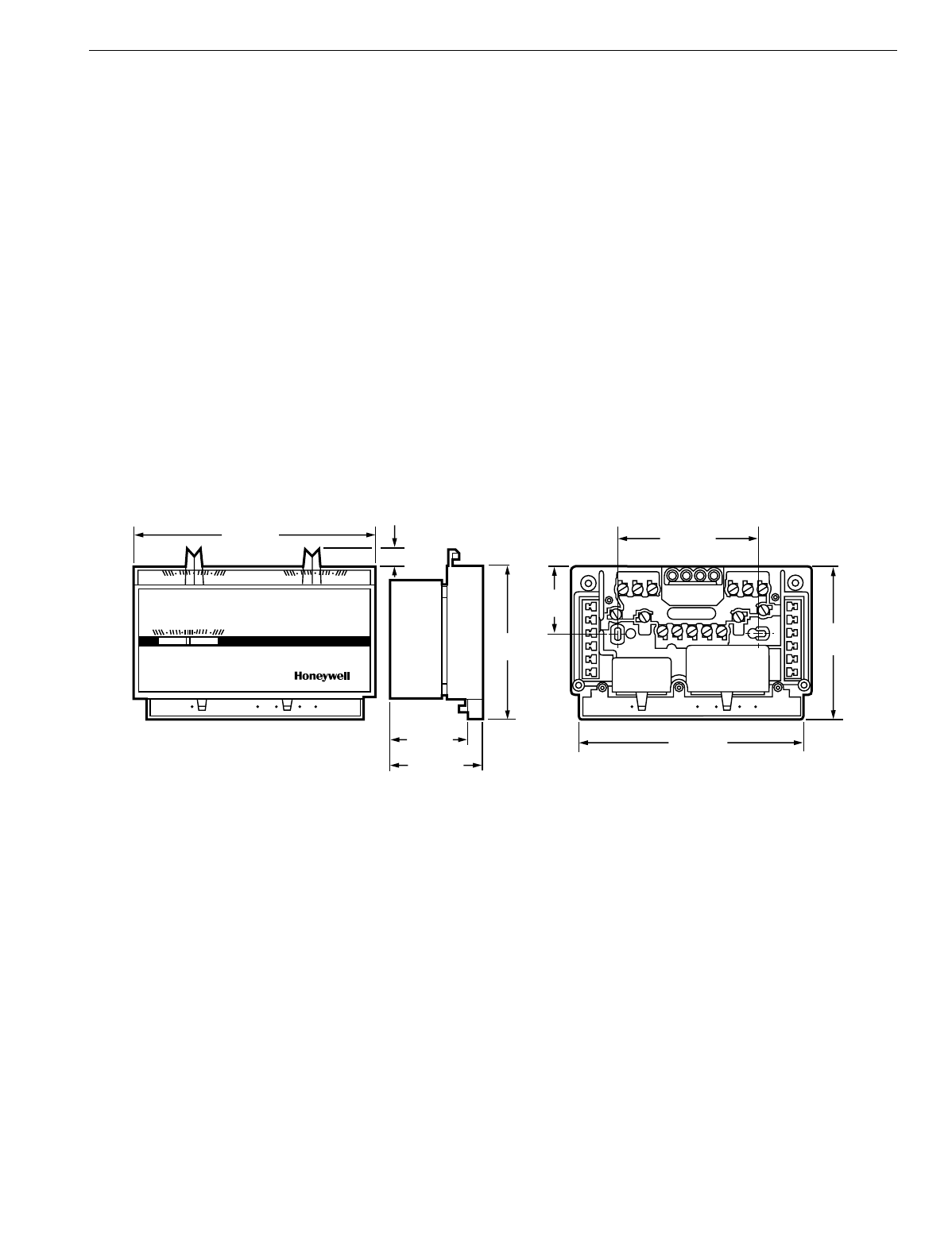
Dimensions: See Fi
g
. 1.
Temperature: Scale Ran
g
e: 42° to 88°F
(
6° to 31°C
)
stan-
dard; optional ran
g
es available.
Thermometer Range: 42° to 88°F
(
6 to 31°C
)
Changeover Differential: 4°F
(
2°C
)
minimum between heat-
in
g
and coolin
g
(
5°F [3°C] on T874W
)
. Levers can be set
apart for
g
reater separation.
Interstage Differential:
Standard Models: Mechanical differential is 1°F
(
0.6°C
)
between heatin
g
or coolin
g
sta
g
es; operatin
g
differential is
approximatel
y
1.9°F
(
1°C
)
between sta
g
es in heatin
g
or
coolin
g
.
Special Models: See Table 3.
Finish: Bei
g
e or Premier White® finish.
Mounting Means: T874 Multista
g
e Thermostat mounts on
Q674 Subbase. Subbase mounts horizontall
y
on wall or
outlet box. Mounts on vertical outlet box with optional
193121A Adapter Plate Assembl
y
.
Fig. 1. T874 Thermostat and Q674 Subbase dimensions in in. (mm).
Optional Specifications (T874 Only):
Temperature scale ran
g
es are 40° to 75°F
(
4° to 24°C
)
heat-
in
g
and 75° to 90°F
(
24° to 32°C
)
coolin
g
with stop; 44° to
68°F
(
7° to 20°C
)
heatin
g
, 80° to 86°F
(
27° to 30°C
)
cool-
in
g
; 6° to 29°C
(
43° to 85°F
)
Celsius scale; 3°to 22°C
(
38°
to 72°F
)
and 26° to 32°C
(
78° to 90°F
)
coolin
g
with stop.
Nonad
j
ustable factor
y
-added stop limits heatin
g
setpoint to
72°F
(
22°C
)
maximum and coolin
g
setpoint to 78°F
(
26°C
)
minimum.
OEM customer personalization.
Lockin
g
cover and lockin
g
lever
(
see Thermostat Accesso-
ries
)
.
Thermostat cover without thermometer.
Ad
j
ustable lockin
g
temperature stops.
Volta
g
e heat anticipation for first or second sta
g
e heat or both.
See Table 3.
Fast c
y
clin
g
on heatin
g
sta
g
e
(
s
)
for electric heat applications.
C815A Outdoor Thermistor for improved performance on
specified models.
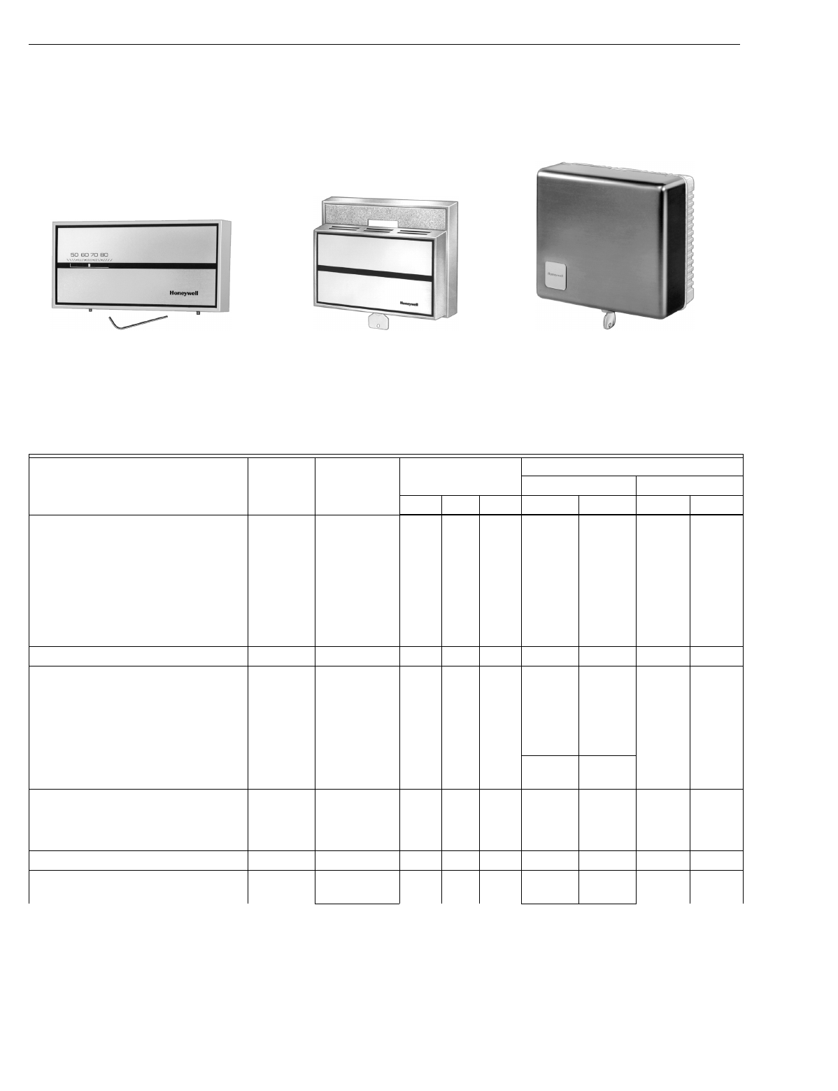
Thermostat Accessories:
Lockin
g
Cover and Lockin
g
Lever Assembl
y
: Part no.
194559R with thermometer; 194559S without thermome-
ter. See Fi
g
. 2. Includes cover, screws, and Allen wrench
for lockin
g
cover. The screws must be used to assure
proper operation.
Ad
j
ustable Lever Stop: Part no. 4074ECK; includes lever stop
and screws.
Universal Versa
g
uard™ Thermostat Guard: Includes wall-
plate, rin
g
base,
g
uard cover, tumbler lock, two ke
y
s and
optional Hone
y
well lo
g
o insert. Double-wall construction
provides extra measure of tamper-resistance. Tamper-
resistant lock; ke
y
cannot be removed without bein
g
in
locked position. Vents in
g
uard base allow airflow for opti-
mum thermostat performance. See form 68-0104 for more
information.
—TG511A1000: Clear cover.
—TG511B1008: Opa
q
ue cover.
—TG511D1004: Painted steel
(
off-white
)
cover. See
Fi
g
. 2.
M5849
FAN
AUTO ON OFF EM. HT. HEAT AUTO COOL
(38)
(87)
SUBBASE
THERMOSTAT MOUNTED
ON SUBBASE
SIDE
50 60 70 80
50 60 70 80 50 60 70 80
HEAT COOL
FAN
AUTO ON OFF EM. HT. HEAT AUTO COOL
(89)
FRONT
2-3/16 (56)
1-7/8 (48)
3-1/2
5-1/8 (130)
1-1/2
3-9/32 (83)
3-7/16
3/8 (10)
5-5/8 (143)
T874 MULTISTAGE THERMOSTATS AND Q674 SUBBASES
60-2485—84
Ke
y
Lock Cover: Part no. TG504A replaces existin
g
T874
cover. Mounts on T874 base and covers thermostat set-
tlin
g
levers and subbase switches. Includes LED window
and two ke
y
s. Should not be used with 193121A Adapter
Plate.
—TG504A1025: Blank face, internal thermometer.
—TG504A1033: External thermometer. See Fi
g
. 2.
Fig. 2. T874 Thermostat accessories.
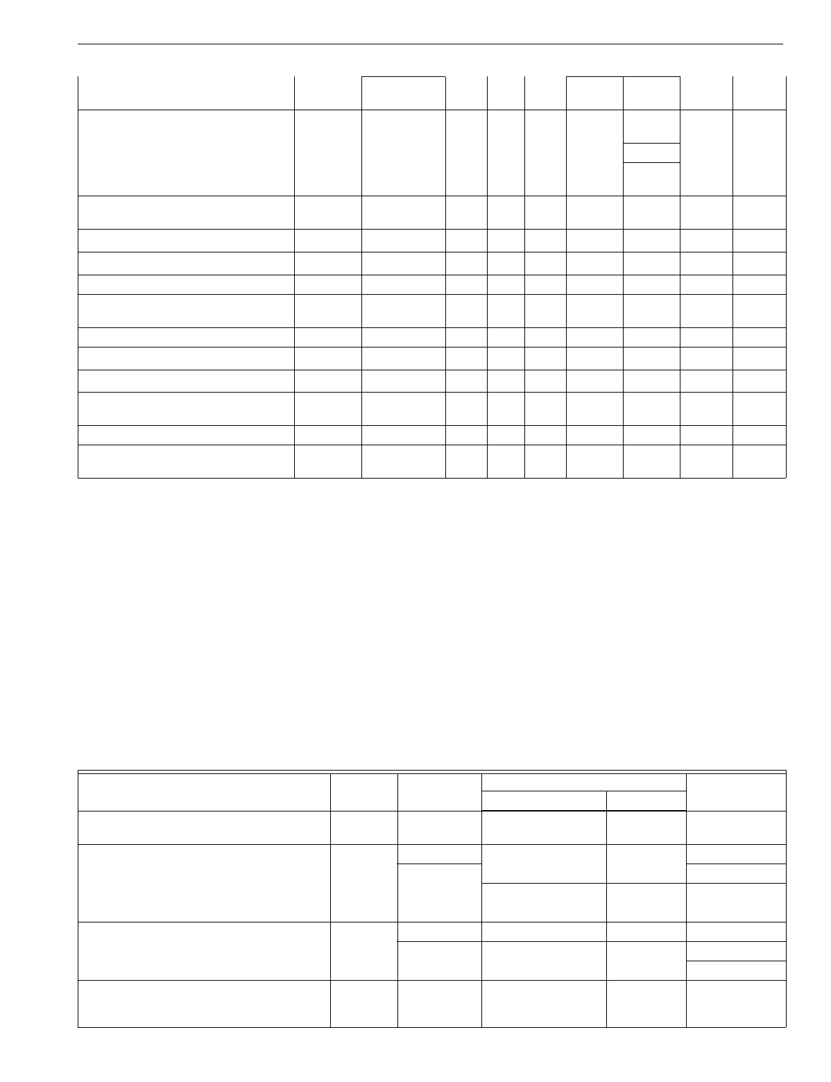
Table 3. T874 Thermostat Specifications.
Models and Options Replaces Applications
System Stages
Anticipation
Heating (Adj) Cooling (Fixed)
Heat Cool Other Stage 1 Stage 2 Stage 1 Stage 2
T874A—Standard and TRADELINE®.
—72°F/78°F
(
22°C/26°C
)
setpoint
stops with lockin
g
cover.
—Ad
j
ustable anticipator set 0.4A.
—Ad
j
ustable lockin
g
temperature
stops
(
TRADELINE®
)
.
—72°F/78°F
(
22°C/26°C
)
setpoint
stops with lockin
g
cover, no
thermometer
(
for DoDa
)
.
T872A Standard 1 1 —0.1-1.2A —0-1.5A —
T874B—Standard and TRADELINE. T872B Standard 1 2 —0.1-1.2A —0-1.2A 0-1.0A
T874C—Standard and TRADELINE.
—72°F/78°F
(
22°C/26°C
)
set stops
with lockin
g
cover, no thermometer
(
for DoDa
)
.
—12°F
(
7°C
)
differential between
H1 and H2 sta
g
es
(
T874C1125
)
.
T872C Standard 2 1 —0.1-1.2A 0.1-1.2A 0-1.5A —
—Fast c
y
clin
g
.0.12-
0.6A 0.12-
0.6A
T874D—Standard and SUPER
TRADELINE®.
—Ad
j
ustable lockin
g
temperature
stops
(
SUPER TRADELINE
)
.
T872D Standard 2 2 —0.1-1.2A 0.1-1.2A 0-1.2A 0-1.0A
T874E—Standard and TRADELINE. T872E 2-Sta
g
e Cool —2—— —0-1.2A 0-1.0A
T874F—Standard and TRADELINE.
—Lockin
g
cover. T872F 2-Sta
g
e Heat 2 ——0.1-1.2A 0.1-1.2A ——
aDepartment of Defense.
bChan
g
eover sta
g
e operates with heatin
g
.
cFixed volta
g
e t
y
pe anticipation.
dChan
g
eover sta
g
e operates with heatin
g
; a secondar
y
chan
g
eover is provided in coolin
g
switch.
eProvides ni
g
ht setback used with standard T874 and timer-operated remote switchin
g
.
fManual chan
g
eover sta
g
e—use Q674B,L subbase.
gChan
g
eover sta
g
e operates with coolin
g
.Q674 Subbases
194559R Locking Cover
with Thermometer
Allen Wrench
TG511D1004 Includes
Painted Steel Cover,
Opaque Base and Wallplate
TG504A1033 Key Lock
Cover with External
Thermometer
T874 MULTISTAGE THERMOSTATS AND Q674 SUBBASES
5 60-2485—8
Models:
See Table 4.
Electrical Ratings:
Switch Contacts: 2.5A at 30 Vac
(
7.5A inrush
)
.
LED Li
g
hts
(
Optional
)
: 30 Vac.
Switches: Two slide switches
(
one switch on Q674G and K;
no switches on Q674D
)
operated b
y
levers. Switch position
is shown on scaleplate.
Mounting: Desi
g
ned to mount horizontall
y
on an outlet box
or the wall. Adapter plate assembl
y
available for mountin
g
on a vertical outlet box
(
see Subbase Accessor
y)
.
Finish: Dark brown or
g
ra
y
.
Dimensions in in. (mm): 3-1/2
(
89
)
hei
g
ht; 5-5/8
(
143
)
width;
5/16
(
8
)
depth. See Fi
g
. 1.
Table 4. Q674 Subbase Specifications.
—Fast c
y
clin
g
. Electric Heat 0.12-
0.6A 0.12-
0.6A
T874G—Heat pump, cool
chan
g
eover, with fast c
y
clin
g
.T872G Heat Pump or
Standard 21
1b0-1.0Ac0.1-1.2A 0-1.0A —
—Fixed anticipator for H2. 0.1-1.5A
—Fast c
y
clin
g
.0.12-
0.6A
T874H—Use with Q674C. T872H Heat Pump or
Standard 11
1b0-1.0Ac—0-1.0A —
T874J—Heat pump. None Heat Pump 2 1 2d0-1.0Ae0-1.5Ac0-1.0Ac—
T874K—Heat pump. None Heat Pump 2 1 1b0.1-1.2A 0-1.5Ac0-1.5A —
T874L—Heat pump. None Heat Pump 2 1 —0.1-1.2A 0.1-1.2A 0-1.5A —
T874N—Heat pump, heat
chan
g
eover. T872N Heat Pump 2 1 1b0.1-1.2A 0.1-1.2A 0-1.0A —
T874P—Heat pump. None Heat Pump 2 1 —0.1-1.2A 0.1-1.2A 0-1.5A —
T874Q—Ni
g
ht setback heatin
g
. T872Q Standard 1e——0.1-1.2A ———
T874R—Heat pump. T872R Heat Pumpf21—0-1.5Ac0.1-1.2A 0-1.5A —
T874S—Two-speed compressor heat
pump. None Heat Pump 2 2 1
g
0-1.2Ac0-1.2Ac0-1.2A 0-1.0A
T874V—Standard. None Standard —1—— —0-1.5A —
T874W—Heat pump and standard.
—Ni
g
ht setback heatin
g
.T872W Heat Pump or
Standard 32—0-1.2Ab0-1.2Ac,d 0-1.2A 0-1.0A
aDepartment of Defense.
bChan
g
eover sta
g
e operates with heatin
g
.
cFixed volta
g
e t
y
pe anticipation.
dChan
g
eover sta
g
e operates with heatin
g
; a secondar
y
chan
g
eover is provided in coolin
g
switch.
eProvides ni
g
ht setback used with standard T874 and timer-operated remote switchin
g
.
fManual chan
g
eover sta
g
e—use Q674B,L subbase.
gChan
g
eover sta
g
e operates with coolin
g
.Q674 Subbases
Models and Options Replaces Application
Switch Positions
Use WithSystem Fan
Q674A—Standard and TRADELINE®.
—Indicator LEDs. Q672A Standard HEAT-AUTO-COOL AUTO-ON T874A-D
Q674B—Standard and TRADELINE. Q672B Standard HEAT-OFF-COOL AUTO-ON T874A-D
—Provision for fan rela
y
operation from Heat Pump T874G,H,L,R
external fan switch
(
isolate G terminal
)
. OVERRIDE-HEAT- AUTO-ON T874P
—Indicator LEDs. OFF-COOL
Q674C—Standard and TRADELINE. Q672C Standard OFF-AUTO AUTO-ON T874A-H,W
—Indicator LEDs. Heat Pump OVERRIDE-AUTO- AUTO-ON T874K,L,N
OFF T874P
Q674D—Standard and TRADELINE.
—For use when subbase switchin
g
is not
re
q
uired.
Q672D Standard None None T874A-F

T874 MULTISTAGE THERMOSTATS AND Q674 SUBBASES
60-2485—86
Optional Specifications (Q674 Only):
Models available with up to four LEDs; for example, LEDs can
show EM. HT, AUX. HT, SERVICE, CHECK, FILTER, and
LOCKOUT. See Fi
g
. 3.
S
y
stem switchin
g
marked HEAT-OFF/RESET-COOL for s
y
s-
tems re
q
uirin
g
impedance rela
y
reset. Available on Q674B
onl
y
.
G terminal isolated on heatin
g
to provide fan rela
y
operation
from external low volta
g
e fan switch
(
Q674B onl
y)
.
Auto fan operation on both heat and cool.
L terminal is used for s
y
stem monitorin
g
devices.
Common R terminal for heatin
g
/coolin
g
.
Chan
g
eover in cool or heat mode for heat pumps.
Auto fan in EM.HT. for heat pumps.
Subbase Accessory: 193121A Adapter Plate Assembl
y
for
mountin
g
on vertical outlet box. Assembl
y
includes adapter
rin
g
and cover plate. Use to cover wall marks from
replaced thermostat.
Fig. 3. Heating, cooling levers and system LED indicators.
Q674E—Standard and TRADELINE. Q672E Standard OFF-HEAT-AUTO-
COOL AUTO-ON T874A-D
Q674F—Two LED models.
—EM.HT. li
g
ht. Q672F Heat Pump OFF-EM.HT.-HEAT-
AUTO-COOL AUTO-ON T874C,D,G,N,S
—Provision for AUTO fan operation in
EM.HT. OFF-COOL-AUTO-
HEAT-EM.HT. AUTO-ON
Q674G—O and B terminals. Q672G Standard OFF-AUTO None T874A-F
Q674J—Provision for AUTO fan operation Q672J Heat Pump EM.HT.-AUTO-OFF AUTO-ON T874A,D,G,J
in EM.HT. EM.HT.-ON-OFF AUTO-ON
—Provision for outdoor thermistor. SUPL.HT.-ON-OFF AUTO-ON
Q674K—Standard. Q672K Standard OFF-HEAT-AUTO-
COOL None T874F
OFF-WOOD-WOOD/
OIL-OIL None
Q674L—Provision for AUTO fan operation in
EM.HT. Q672L Heat Pump EM.HT.-HEAT-OFF-
COOL AUTO-ON T874R,W
—Indicator LEDs. SUPL.HT.-HEAT-
OFF-COOL AUTO-ON
Q674N—Standard. Q672N Evaporative
Cooler EVAP-COOL-OFF-
HEAT AUTO-ON T874C
Q674P—Standard. Q672P Heat Pump SUPL.HT.-HEAT-
COOL AUTO-ON T874G
Q674Q—Standard. None Fan Coil HEAT-OFF-COOL LO-MED-HI-
ON T874A
Q674R—Standard.
—International s
y
mbols. None Fan Coil OFF-COOL LO-HI-
CONT. T874V
Q674S—Indicator LED. None Standard HEAT-COOL None T874C
T874 Thermostat with
One Setpoint Lever Q674 Subbase
with Four LEDs
T874 Thermostat with
Separate
Heatin
g
and Coolin
g
Levers
T874 MULTISTAGE THERMOSTATS AND Q674 SUBBASES
7 60-2485—8
MERCURY NOTICE
This control contains mercur
y
in a sealed tube. Do
not
place control in the trash at the end of its useful life.
If this control is replacin
g
a control that contains
mercur
y
in a sealed tube, do
not
place
y
our old control
in the trash.
Contact
y
our local waste mana
g
ement authorit
y
for
instructions re
g
ardin
g
rec
y
clin
g
and the proper
disposal of this control, or of an old control containin
g
mercur
y
in a sealed tube. If
y
ou have
q
uestions, call
the Hone
y
well Customer Response Center at
1-800-468-1502.
INSTALLATION
When Installing this Product…
1. Read these instructions carefull
y
. Failure to follow them
could dama
g
e the product or cause a hazardous condi-
tion.
2. Check the ratin
g
s
g
iven on the product to make sure the
product is suitable for
y
our application.
3. Installer must be a trained, experienced service techni-
cian.
4. After installation is complete, check out product opera-
tion as provided in these instructions.
CAUTION
Hazardous Voltage.
Can damage heating/cooling system.
1. Disconnect power suppl
y
before be
g
innin
g
instal-
lation to prevent electrical shock or e
q
uipment
dama
g
e.
2. Do
not
short across coil terminals on rela
y
. This
can burn out thermostat heat anticipator.
3. To prevent interference with the thermostat link-
a
g
e, keep wire len
g
th to a minimum and run wires
as close as possible to the subbase.
4. Do
not
overti
g
hten thermostat captive mountin
g
screws because dama
g
e to subbase threads can
result.
IMPORTANT
An incorrectly leveled thermostat will cause the tem-
perature control to deviate from setpoint. It is not a
calibration problem.
Location
Install the thermostat about 5 ft
(
1.5m
)
above the floor in an
area with
g
ood air circulation at avera
g
e temperature.
Do not mount the thermostat where it can be affected b
y
:
—drafts or dead spots behind doors, in corners or under
cabinets.
—hot or cold air from ducts.
—radiant heat from the sun, fireplace, or appliances.
—concealed pipes and chimne
y
s.
—unheated
(
uncooled
)
areas such as an outside wall behind
the thermostat.
Mount Subbase
The subbase can be mounted on a vertical outlet box,
horizontal outlet box or directl
y
on the wall.
1. If the subbase is mounted on a vertical outlet box, order
Hone
y
well part no. 193121A Adapter Assembl
y
. See
Fi
g
. 4. The assembl
y
includes an adapter rin
g
, two
screws and a cover plate to cover marks on the wall.
Install the rin
g
and cover plate on the vertical outlet box.
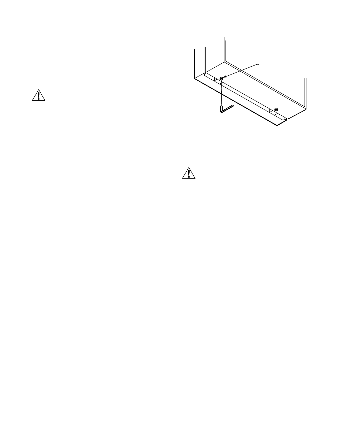
NOTE: For a wall installation, hold subbase in position and
mark holes for anchors. See Fi
g
. 5. Wall anchors
must be obtained from local hardware store. Be
careful that the wires do not fall back into the wall
openin
g
. Set aside subbase. Drill four
3/16 in.
(
4.8 mm
)
holes and
g
entl
y
tap anchors into
the holes until flush with the wall.
2. Pull wires throu
g
h the cover plate
(
if used
)
and subbase
cable openin
g
. See Fi
g
. 6.
3. Secure the cover plate
(
if used
)
and subbase with the
screws provided. Do not full
y
ti
g
hten the subbase
screws.
Level the subbase usin
g
a spirit level, see Fi
g
. 7, and firml
y
ti
g
hten subbase mountin
g
screws. The subbase mountin
g
holes provide for minor out-of-level ad
j
ustments.
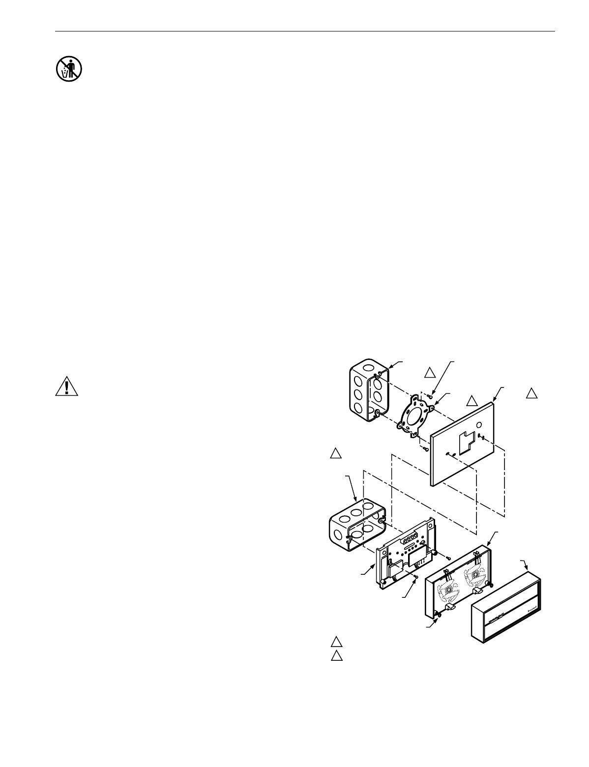
Fig. 4. Installing Q674 Subbase on outlet box.
M6009
VERTICAL
OUTLET
BOX
ADAPTER
RING
COVER
PLATE
MOUNTING
SCREWS (2)
1
SUBBASE
SUBBASE
MOUNTING SCREWS (2)
HORIZONTAL
OUTLET
BOX
1
2
2
1 NOT INCLUDED WITH UNIT.
2 ACCESSORY PART AVAILABLE (193121A).
THERMOSTAT
CAPTIVE
MOUNTING SCREWS (2)
50 60 70 80
50 60 70 80
HEATCOOL
THERMOSTAT
COVER
50 60 70 80
T874 MULTISTAGE THERMOSTATS AND Q674 SUBBASES
60-2485—88
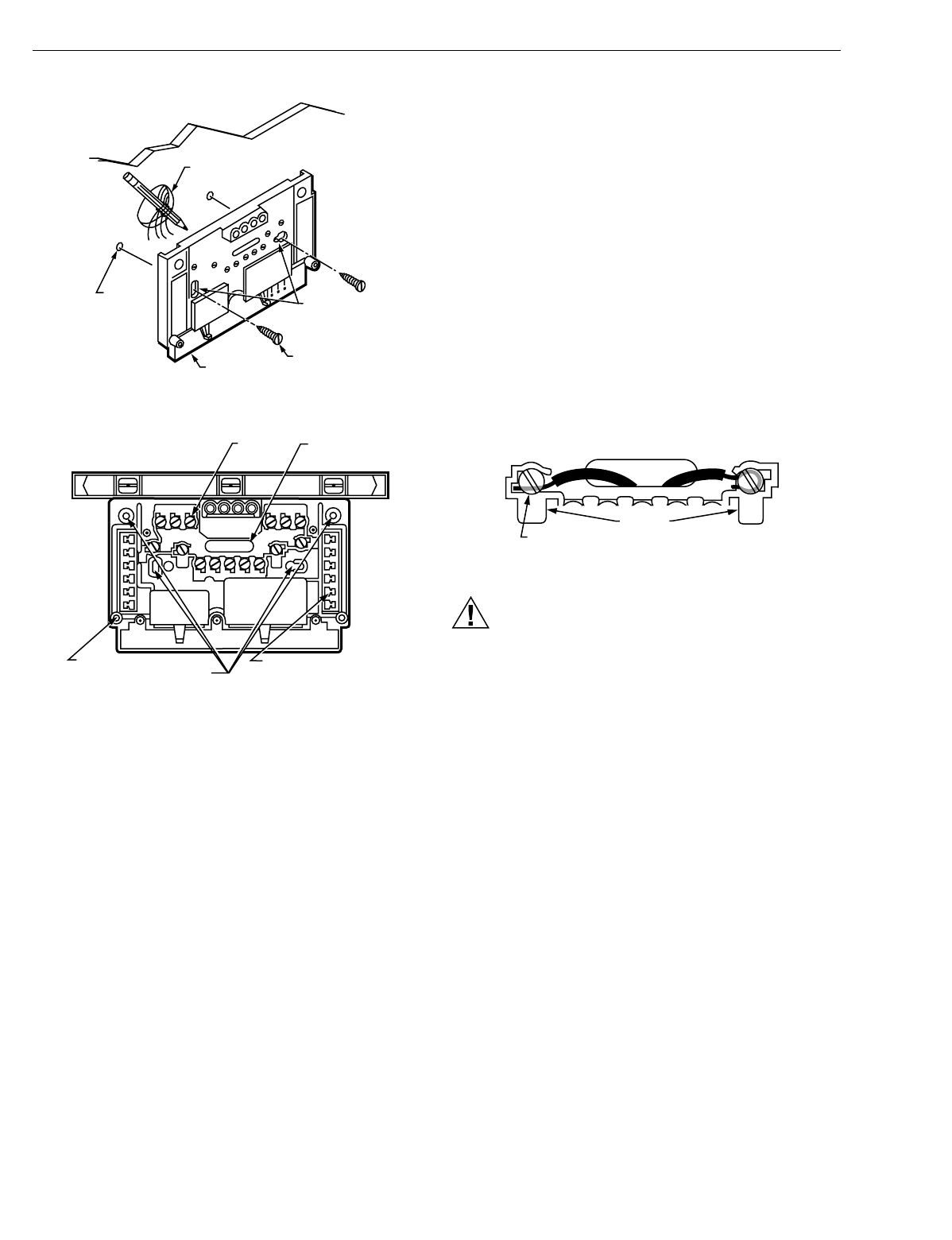
Fig. 5. Installing Q674 Subbase on wall.
Fig. 6. Subbase components and leveling procedure.
Wire Subbase
Disconnect power suppl
y
before be
g
innin
g
installation to
prevent electrical shock or e
q
uipment dama
g
e.
All wirin
g
must compl
y
with local electrical codes and
ordinances.
IMPORTANT
Use 18 gauge, solid-conductor wire whenever possi-
ble. If using 18 gauge stranded wire, no more than
10 wires can be used. Do not use larger than
18 gauge wire.
Follow e
q
uipment manufacturer wirin
g
instructions when
available. To wire subbase, proceed as follows:
1. Connect the s
y
stem wires to the subbase as shown in
the applicable dia
g
ram. A letter code is located near
each terminal for identification. T
y
pical terminal desi
g
-
nation and wirin
g
connections are listed in Table 5. The
terminal barrier permits strai
g
ht or wraparound wirin
g
connection. See Fi
g
. 7. The subbase can re
q
uire one or
more
j
umpers that ma
y
or ma
y
not be factor
y
-supplied.
See Fi
g
. 8 and the wirin
g
dia
g
rams for specific terminals
to be
j
umpered.
Fig. 7. Barrier configuration.
CAUTION
Equipment Damage Hazard.
Never install more than one wire per terminal unless
usin
g
factor
y
-supplied
j
umper with spade terminal.
2. Firml
y
ti
g
hten each terminal screw.
3. Fit wires as close as possible to the subbase. Push
excess wire back into the hole.
4. Plu
g
hole with nonflammable insulation to prevent drafts
from affectin
g
the thermostat.
WIRES THROUGH
WALL OPENING
WALL
WALL
ANCHORS
(2)
SUBBASE
MOUNTING
SCREWS (2)
M926
MOUNTING
HOLES
SPIRIT LEVEL
M927
WIRING
TERMINAL THERMOSTAT
CABLE OPENING
TO SPRING FINGER
CONTACTS ON
THE THERMOSTAT
(
UP TO 12
)
MOUNTING
HOLES (4)
POST FOR
MOUNTING
THERMOSTAT (2)
FOR STRAIGHT
INSERTION–
STRIP 5/16 IN. (8 MM)
FOR WRAPAROUND–
STRIP 7/16 IN. (11 MM)
SUBBASE TERMINAL SCREW M928
BARRIER
T874 MULTISTAGE THERMOSTATS AND Q674 SUBBASES
9 60-2485—8
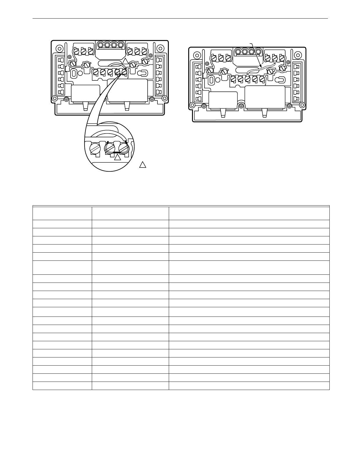
Fig. 8. Jumper adjacent terminals for special system hookup using stripped wire 3/4 in. (19 mm).
For nonadjacent terminals and using jumper wire supplied with subbase.
Table 5. Terminal Designationsa
Standard Terminal
Designation Alternate Designations or
Customer Specials Typical Connection
BHeatin
g
damper motor; chan
g
eover valve
EKEmer
g
enc
y
heat rela
y
G F Fan rela
y
coil
LS
y
stem monitor
ORCoolin
g
damper motor; chan
g
eover valve
R V Power connection to transformer
(
internall
y
connected for heatin
g
and coolin
g)
RC Power connection to coolin
g
transformer
RH Power connection to heatin
g
transformer
W1 H1, R3 Sta
g
e 1 heatin
g
control
W2 H2, Y, R4 Sta
g
e 2 heatin
g
control
W3 Sta
g
e 3 heatin
g
controlb
Y1 C1, M Sta
g
e 1 coolin
g
control
Y2 C2 Sta
g
e 2 coolin
g
control
Y3 Sta
g
e 3 coolin
g
control
XX1,X2,CClo
gg
ed filter switch or common connection
T A Outdoor thermistor
L, C, H HSII control panel
PDefrost
O Momentar
y
circuit, chan
g
eover
A, A1, A2, Z, C, L LEDs
aOther terminal desi
g
nations can be used that are not listed on this table. Refer to the hookup drawin
g
and internal schematic
for exact connections.
bW3 controls the auxiliar
y
heat like W2, and allows addin
g
additional sta
g
es of auxiliar
y
heat with outdoor thermostats while
maintainin
g
the proper second sta
g
e anticipation.
M5899
1
1
1 TWO ADJACENT TERMINALS SHOWN JUMPERED ARE FOR EXAMPLE ONLY. COMPARE WIRING
DIAGRAM AND SUBBASE TO IDENTIFY TERMINALS TO BE JUMPERED.
JUMPER WIRE
(SUPPLIED WITH SOME MODELS)
T874 MULTISTAGE THERMOSTATS AND Q674 SUBBASES
60-2485—810
Outdoor Disconnect
The National Electrical Code re
q
uires the installation of a
disconnect switch w
ithin
si
g
ht of the outdoor unit of an air
conditioner or heat pump. The switch is for the safet
y
of an
y
technician workin
g
on the unit. The technician can assure that
the unit
remains
unpowered.
Install and Adjust Stop Brackets
The stop brackets should be installed onl
y
if there is a need to
restrict the ad
j
ustable ran
g
e of the heatin
g
and coolin
g
temperature setpoint levers. If ad
j
ustable lever stops are
desired, order 4074ECK Envelope Assembl
y
, which contains
two ad
j
ustable lever stop brackets, one brass insert, one
mountin
g
screw and two lockin
g
screws with insulated heads.
When installed, the stop brackets limit the movement of the
T874 HEAT and COOL levers.
TO INSTALL:
1. Remove the thermostat cover b
y
pullin
g
the bottom
ed
g
e of the cover upward until it snaps free of the
mountin
g
slots.
2. Turn to the back of the T874 Thermostat. Locate the
hole for the brass insert in the plastic base below the
LED window.
3. Push the brass insert into the hole with fin
g
er.
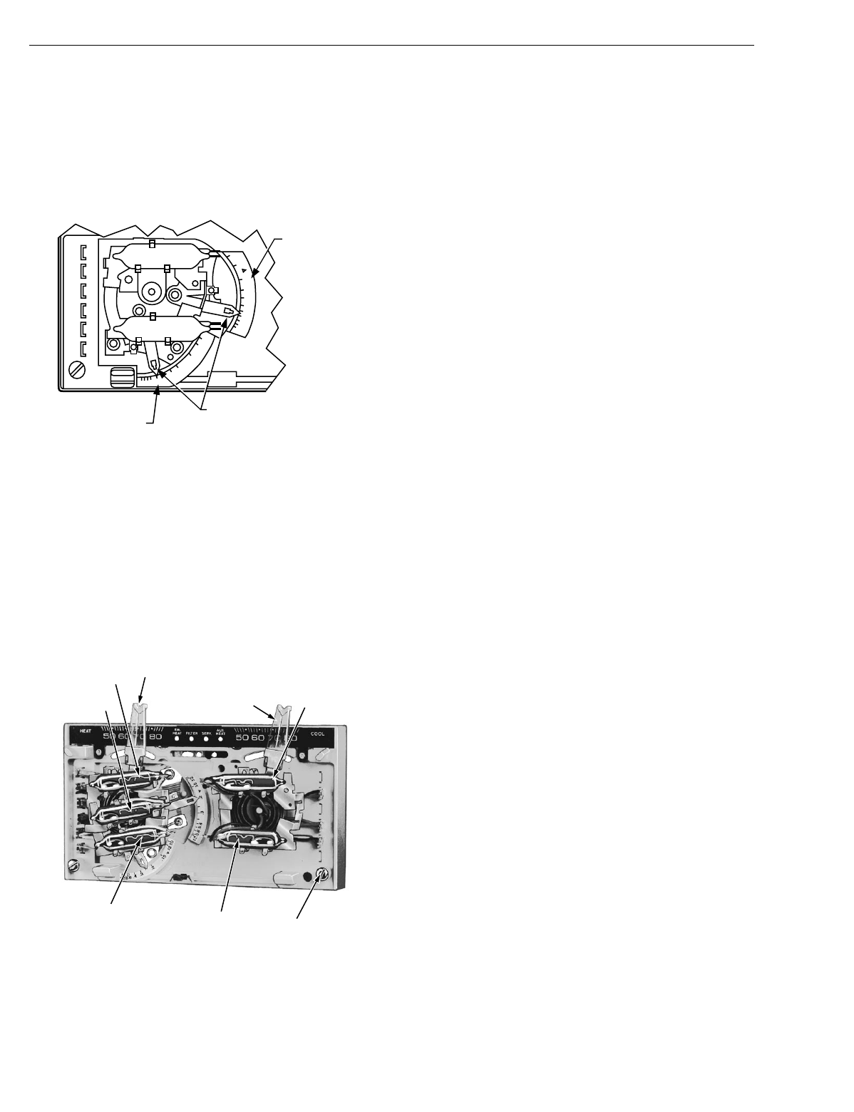
4. Turn to the front of the T874 Thermostat.
5. Place the two stop brackets in position with the tabs in
the slot between the HEAT and COOL levers. See
Fi
g
. 9.
Fig. 9. Range limiting and lever locking methods.
6. Insert the mountin
g
screw into the two slots in the stop
brackets and attach to the brass insert. Ti
g
hten the
screw to pull the brass insert into the back of the ther-
mostat.
7. Loosen the mountin
g
screw enou
g
h to free the stop
brackets for ad
j
ustment.
T External temperature readout, T rela
y
R1, R2 LO and HI speed fan rela
y
s
RS Coolin
g
contactor
Y M Compressor contactor
Table 5. Terminal Designationsa
Standard Terminal
Designation Alternate Designations or
Customer Specials Typical Connection
aOther terminal desi
g
nations can be used that are not listed on this table. Refer to the hookup drawin
g
and internal schematic
for exact connections.
bW3 controls the auxiliar
y
heat like W2, and allows addin
g
additional sta
g
es of auxiliar
y
heat with outdoor thermostats while
maintainin
g
the proper second sta
g
e anticipation.
HEAT
LEVER
HOLES FOR INSULATED
LOCKING LEVER SCREWS
COOL
LEVER HOLE WITH
BRASS INSERT
BRACKET
TABS
ADJUSTABLE
LEVER STOP
BRACKETS BRACKET
SLOTS
MOUNTING
SCREW
ADJUSTABLE STOPS
ADJUSTABLE LOCKING LEVERS
NONADJUSTABLE STOPS
WITH LOCKING LEVER SCREWS
75°F (24°C) MAX. HEAT
75°F (24°C) MIN. COOL
NONADJUSTABLE D.O.D. STOPS
72°F (22°C) MAX. HEAT
78°F
(
26°C
)
MIN. COOL M7626
T874 MULTISTAGE THERMOSTATS AND Q674 SUBBASES
11 60-2485—8
8. Move the HEAT and COOL levers to the maximum tem-
perature desired.
9. Slide the stop brackets until one rests a
g
ainst the HEAT
lever and the other a
g
ainst the COOL lever.
10. Firml
y
ti
g
hten the mountin
g
screw.
11. If the HEAT and COOL levers are to be locked in place
at a specific temperature, use the two insulated head
screws supplied instead of the two ad
j
ustable lever stop
brackets.
CAUTION
Equipment Damage Hazard.
Do
not
use standard screws that provide metal-to-
metal contact with the stop brackets. Short circuit and
potential e
q
uipment dama
g
e can result.
Mount Thermostat
1. Remove the thermostat cover b
y
pullin
g
the bottom
ed
g
e of the cover awa
y
from the base until it snaps free
of the cover clip.
NOTE: The cover is hin
g
ed at the top and must be removed
b
y
pullin
g
up at the bottom.
2. Carefull
y
remove and discard the pol
y
st
y
rene packin
g
insert that protects the mercur
y
switches durin
g
ship-
ment.
3. If LED indication
(
EM.HT., CHECK, etc.
)
is to be used
with the Q674 Subbase, install the preprinted insert
under the thermostat setpoint scale. To install, push
both thermostat setpoint levers to the far ends of the
thermostat. Use index fin
g
er to
g
entl
y
pull out the plastic
setpoint scale about 1/4 in.
(
6 mm
)
. Position the desired
preprinted insert in the space above the LED li
g
hts.
Reposition setpoint levers.
4. Turn over the thermostat base and note the sprin
g
fin-
g
ers that en
g
a
g
e the subbase contacts. Make sure the
sprin
g
fin
g
ers are
not
bent flat, preventin
g
proper elec-
trical contact with the subbase.
5. Set the heat anticipator indicator
(
s
)
to the respective
current settin
g
of each sta
g
e. See Set The Heat Antici-
pator section.
6. If the thermostat provides optional lockin
g
cover assem-
bl
y
, start the Allen lockin
g
screws in the cover with the
wrench provided. See Fi
g
. 10.
7. Note the two tabs alon
g
the top inside ed
g
e of the ther-
mostat base. The tabs fit into correspondin
g
slots on top
of the subbase. Mount the thermostat on the subbase.
8. Ali
g
n the two captive mountin
g
screws in the thermostat
base with the posts on the subbase. Ti
g
hten both
screws.
Do not overtighten screws
or dama
g
e to sub-
base posts can result.
Fig. 10. Installation of locking cover assembly.
SETTINGS
CAUTION
Equipment Damage Hazard.
On s
y
stems usin
g
a
g
as valve, never appl
y
a
j
umper
across the valve coil terminals, even temporaril
y
. This
can burn out thermostat heat anticipator
(
s
)
.
Set the Heat Anticipator
Move the indicator to match the primar
y
control current draw.
When usin
g
a T874 Thermostat with two sta
g
es of heatin
g
,
set each heat anticipator to match its respective primar
y
control current draw. If
y
ou cannot find the current ratin
g
on
the primar
y
control, or if further ad
j
ustment is necessar
y
, see
NOTE and use the followin
g
procedure to determine the
current draw of each sta
g
e.
The current draw of each heatin
g
sta
g
e must be measured
with the thermostat removed and power on to the heatin
g
s
y
stem.
1. Connect an ac ammeter of appropriate ran
g
e between
the heatin
g
terminals of the subbase:
a. Sta
g
e 1—between W1 and RH or R;
b. Sta
g
e 2—between W2 and RH or R
c. Sta
g
e 3—between W3 and RH or R.
2. Move the s
y
stem switch to HEAT or AUTO.
3. After one minute, read the ammeter and record the
readin
g
:
a. Sta
g
e 1—__________A;
b. Sta
g
e 2—__________A;
c. Sta
g
e 3—__________A.
NOTE: If e
q
uipment c
y
cles too fast, set the indicator to a
hi
g
her current ratin
g
, but not more than one-half divi-
sion at a time, and recheck the c
y
cle rate. Most con-
ventional two-sta
g
e heatin
g
e
q
uipment is desi
g
ned
to operate at three c
y
cles per hour per sta
g
e, and
one-sta
g
e heatin
g
e
q
uipment at six c
y
cles per hour,
at 50 percent load conditions. When usin
g
the T874
Thermostat in heat pump s
y
stems, set the heat
ALLEN
RETAINING
SCREWS (2)
M956
T874 MULTISTAGE THERMOSTATS AND Q674 SUBBASES
60-2485—812
anticipator at 140 percent of the actual primar
y
con-
trol current draw to reduce the c
y
clin
g
rate. See Fi
g
.
11.
Most heat pump s
y
stems should c
y
cle 2-1/2 to 3 times per hour.
4. Han
g
the upper ed
g
e of the thermostat cover on top of
the thermostat base and swin
g
the cover downward
until it en
g
a
g
es with the cover clip.
Fig. 11. Adjustable heat anticipator scales.
Temperature Setting
Move the heatin
g
and coolin
g
levers to the desired comfort
positions. See Fi
g
. 12. On some models with two sta
g
es of
heatin
g
or coolin
g
, the same lever controls both sta
g
es. The
minimum differential between heatin
g
and coolin
g
setpoints is
4°F
(
2°C
)
(
5°F [3°C]
)
on T874W.
If model has optional screws to lock temperature control
levers, loosen these screws before makin
g
temperature
ad
j
ustment; ti
g
hten the screws when levers are set at desired
position.
Fig. 12. Internal view of T874W (three stages of
heating, two stages of cooling).
Subbase Setting
The subbase switchin
g
positions control the s
y
stem operation
as described below.
SYSTEM SWITCH
(
see subbase for positions
)
:
OFF—both the heatin
g
and coolin
g
s
y
stems are off. If the
fan switch is at the AUTO position, the coolin
g
fan is
also off.
HEAT—heatin
g
s
y
stem is automaticall
y
controlled b
y
the
thermostat. Coolin
g
s
y
stem is off.
AUTO—thermostat automaticall
y
chan
g
es between heat-
in
g
and coolin
g
s
y
stem operation, dependin
g
on the
indoor temperature.
COOL—coolin
g
s
y
stem is automaticall
y
controlled b
y
the
thermostat. Heatin
g
s
y
stem is off.
EM.HT.—emer
g
enc
y
heat rela
y
is automaticall
y
controlled
b
y
the thermostat. Coolin
g
s
y
stem is off. Compressor is
de-ener
g
ized.
SUPL.HT.—supplemental heat rela
y
is ener
g
ized. Coolin
g
s
y
stem is off. Compressor is de-ener
g
ized.
WOOD—heatin
g
s
y
stem is operatin
g
with onl
y
the wood-
burnin
g
sta
g
e.
OIL—heatin
g
s
y
stem is operatin
g
with onl
y
the oil-burnin
g
sta
g
e.
WOOD/OIL—wood and oil sta
g
es operate se
q
uentiall
y
;
first the WOOD sta
g
e operates, then the OIL sta
g
e
operates if the WOOD sta
g
e cannot handle the load.
EVAP—controls coolin
g
s
y
stem b
y
water evaporation; see
e
q
uipment instructions for further information.
OVERRIDE—ni
g
ht setback is disabled.
ON—heatin
g
s
y
stem is controlled b
y
the thermostat. EM.
HT. or SUPL. HT. rela
y
is not ener
g
ized.
FAN SWITCH positions control fan operation as follows:
ON or CONT.—fan operates continuousl
y
.
AUTO—fan operates as controlled b
y
the thermostat in
heat pump s
y
stems or conventional coolin
g
mode; fan
operates as controlled b
y
the plenum switch in conven-
tional heatin
g
mode.
LO—fan operates constantl
y
at low speed.
MED—fan operates constantl
y
at medium speed.
HI—fan operates constantl
y
at hi
g
h speed.
To move the subbase switches to the desired control
positions, use thumb and index fin
g
er to slide the lever. The
lever must stop over desired function indicator position for
proper circuit operation.
Sprin
g
return momentar
y
position switchin
g
feature is
available on selected subbase models. On these models, the
fan switch is positioned to the ri
g
ht of the s
y
stem switch. B
y
movin
g
the fan switch to the far ri
g
ht and releasin
g
it, the ON
position circuit makes. The lever sprin
g
s back on release. This
position is not marked on the subbase.
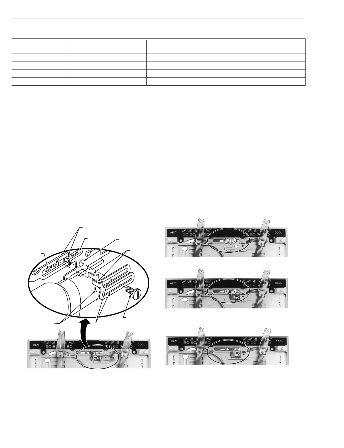
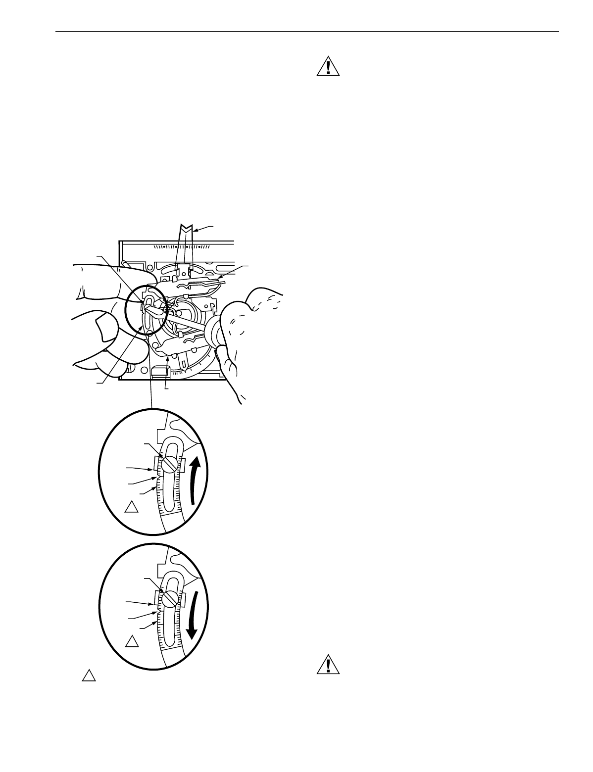
Setting the Adjustable Differential
The ad
j
ustable intersta
g
e differential feature, on a selected
T874D model onl
y
, can be identified b
y
the scale and tension
screw near the heatin
g
and coolin
g
mercur
y
switches. See
Fi
g
. 13. On this model, the number of de
g
rees between the
makin
g
of the first and second sta
g
e mercur
y
bulbs is
ad
j
ustable. This feature is especiall
y
useful if the first sta
g
e
controls the comfort temperature, and the second sta
g
e
controls the ener
gy
savin
g
s temperature. Timers, such as the
S6005, for insertion between the first and second sta
g
e
control points must be ordered separatel
y
.
1.2
.4
.6
.3
.2 .15
.12
.10
.8
1.2
.4
.6
.3
.2 .15
.12
.8
.5
MOVE INDICATOR TO
MATCH CURRENT RATING
OF PRIMARY CONTROL
STAGE ONE
ANTICIPATOR
HEATING
CONTROL
STAGE TWO
ANTICIPATOR
HEATING CONTROL
M5069
STAGE 1
HEATING
STAGE 3
HEATING
STAGE 2
HEATING
HEATING
LEVER COOLING
LEVER STAGE 1
COOLING
STAGE 2
COOLING
CAPTIVE
MOUNTING
SCREWS (2) M7625
T874 MULTISTAGE THERMOSTATS AND Q674 SUBBASES
13 60-2485—8
Each mark on the scale represents 1°F
(
0.6°C
)
The
differential is factor
y
set at 2°F
(
1°C
)
the differential can be set
as hi
g
h as 12°F
(
7°C
)
To set the ad
j
ustable intersta
g
e
differential, loosen the tension screw. See Fi
g
. 13. Slide the
ad
j
ustable scale to ali
g
n with the number of de
g
rees desired
between sta
g
es. Use the lower ed
g
e of the tension screw
bracket as a
g
uide for ali
g
nment. In heatin
g
, slide the lever
wider
apart for a
larger
differential, or
closer
to
g
ether for a
smaller
differential. In coolin
g
, slide the lever
closer
to
g
ether
for a
larger
differential, or
wider
apart for a
smaller
differential.
While supportin
g
the scale with hand, ti
g
hten the tension screw.
IMPORTANT
Support the scale with hand while tightening tension
screw. See Fig. 13. Failure to do so can result in
twisting and damaging bimetal coil.
Fig. 13. Set adjustable interstage differential.
CAUTION
Equipment Damage Hazard.
When the thermostat is used to control a two-sta
g
e
heatin
g
or coolin
g
s
y
stem, the second sta
g
e mercur
y
bulb must never make before the first sta
g
e bulb, or
severe e
q
uipment dama
g
e could result. To prevent
this problem, provide at least 2°F
(
1°C
)
differential
between sta
g
e-one and sta
g
e-two make points.
Example: in heatin
g
, if sta
g
e-one makes at 70°F
(
21°C
)
sta
g
e-two should make at 68°F
(
20°C
)
or lower.
Verify the Adjustment
Heating
Start with the heatin
g
setpoint lever all the wa
y
to the left.
Slowl
y
move the lever to the ri
g
ht,
j
ust until the first sta
g
e bulb
makes
(
mercur
y
rolls to the ri
g
ht side of the bulb
)
. Note the
settin
g
on the temperature scale. Slowl
y
move the lever to the
ri
g
ht until the second sta
g
e bulb makes. Note the settin
g
on
the temperature scale. The difference between the two
temperatures is the
interstage differential,
which should match
the number set on the scale with the tension screw.
Cooling
Start with the coolin
g
setpoint lever all the wa
y
to the ri
g
ht.
Slowl
y
move the lever to the left,
j
ust until the first sta
g
e bulb
makes
(
mercur
y
rolls to the left side of the bulb
)
. Note the
settin
g
on the temperature scale. Slowl
y
move the lever to the
left until the second sta
g
e bulb makes. Note the settin
g
on the
temperature scale. The difference between the two
temperatures is the
interstage differential,
which should match
the number set on the scale with the tension screw.
CHECKOUT
Heating
Move the s
y
stem switch on the Q674 Subbase to HEAT or
AUTO. Move the heat lever on the T874 about 10°F
(
6°C
)
above room temperature. See Fi
g
. 12. Heatin
g
s
y
stem should
start and the fan should run after a short dela
y
. Move the heat
lever about 10°F
(
6°C
)
below room temperature. The heatin
g
e
q
uipment should shut off, and the fan should run for a short
time, then shut off.
In heat pump applications, sometimes time dela
y
s are
involved before the compressor and auxiliar
y
heat are
activated. This is due to a minimum-off timer, which prevents
the compressor from restartin
g
for five minutes from when the
thermostat last turned off the compressor, or from when the
s
y
stem first received power.
Cooling
CAUTION
Equipment Damage Hazard.
Do not operate coolin
g
if outdoor temperature is below
50°F
(
10°C
)
. Refer to manufacturer recommendations.
TENSION
SCREW
ALIGN LOWER
EDGE WITH
SCALE
NOTCH
10°F
SCALE
1
SLIDE LEVER
WIDER APART
FOR LARGER
DIFFERENTIAL
HEATING
TENSION
SCREW
ALIGN LOWER
EDGE WITH
SCALE
NOTCH
4°F
SCALE
1
SLIDE LEVER
CLOSER TOGETHER
FOR LARGER
DIFFERENTIAL
COOLING
1 EACH MARK ON THE SCALE REPRESENTS 1°F (0.6°C). M937
1.2
.8
.6
.3
.2
1.5
.4
50 60 70 80
HEAT
TENSION
SCREW
HEATING SET-
POINT LEVER
FIRST
STAGE
SWITCH
SECOND STAGE
(ADJUSTABLE)
SWITCH
SCALE
T874 MULTISTAGE THERMOSTATS AND Q674 SUBBASES
60-2485—814
Move the s
y
stem switch on the Q674 Subbase to COOL or
AUTO. Move the cool settin
g
lever on the T874 Multista
g
e
Thermostat about 10°F
(
6°C
)
below room temperature. See
Fi
g
. 12. The coolin
g
e
q
uipment and fan should start. If the
s
y
stem has two sta
g
es of coolin
g
, both sta
g
es should start.
Move the cool lever about 10°F
(
6°C
)
above room
temperature. The coolin
g
e
q
uipment and fan should stop.
Fan
Move the s
y
stem switch to COOL, OFF, or AUTO. If
necessar
y
, position both temperature settin
g
levers so that the
heatin
g
and coolin
g
e
q
uipment are off. Move the fan switch to
ON or CONT. The fan should run continuousl
y
. When the fan
switch is in AUTO, LO, MED, or HI position, fan operation is
controlled b
y
the heatin
g
or coolin
g
s
y
stem.
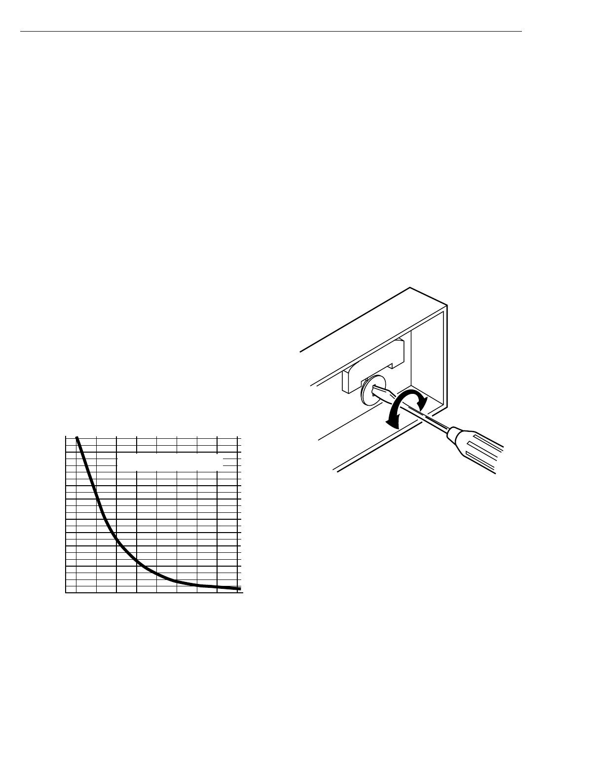
Outdoor Reset Thermistor (Where
Applicable)
If the s
y
stem is supplied with a thermistor, it must be used; if
not used, thermostat performance deviates radicall
y
from
proper operation.
The proper thermistor operation must be verified to ensure the
correct operation of the thermostat. Check thermistor
operations as follows:
1. Disconnect the T wire on the subbase.
2. Use an ohmmeter to measure resistance between the
T wire and the A subbase terminal.
3. Take outdoor temperature at thermistor location and find
the correct thermistor resistance on the Fi
g
. 14 chart.
4. If the resistance measured in step 2 and the calculated
resistance in step 3 var
y
b
y
more than 15 percent, the
thermistor re
q
uires replacement. Contact Hone
y
well or
installin
g
dealer for replacement packa
g
ed outdoor ther-
mistor, part no. C815A1005.
Fig. 14. Thermistor resistance chart.
CALIBRATION
Thermostat
T874 Thermostats are accuratel
y
calibrated at the factor
y
.
They do not have provision for field calibration.
Thermometer
The thermometer in
y
our thermostat has been accuratel
y
calibrated at the factor
y
. The thermometer should onl
y
need
ad
j
ustment if it has been dropped or shifted due to mishandlin
g
.
If the setpoint lever and the thermometer readin
g
do not
a
g
ree, use the followin
g
procedure:
1. Remove the thermostat cover b
y
pullin
g
up from the
bottom ed
g
e of the cover awa
y
from the base until it
snaps free of the cover clip.
2. Set the thermostat cover on a table near an accurate
thermometer.
3. Allow ten minutes for cover thermometer to sense area
temperature; compare the readin
g
s. Be careful not to
touch thermometer or breathe on it.
4. If the readin
g
s are the same, replace cover and put the
s
y
stem into operation.
5. If the readin
g
s are different, insert a small screwdriver in
the thermometer slot and turn it until the thermometers
have the same readin
g
. See Fi
g
. 15.
6. Replace thermostat cover and put the s
y
stem into oper-
ation.
Fig. 15. Thermometer calibration.
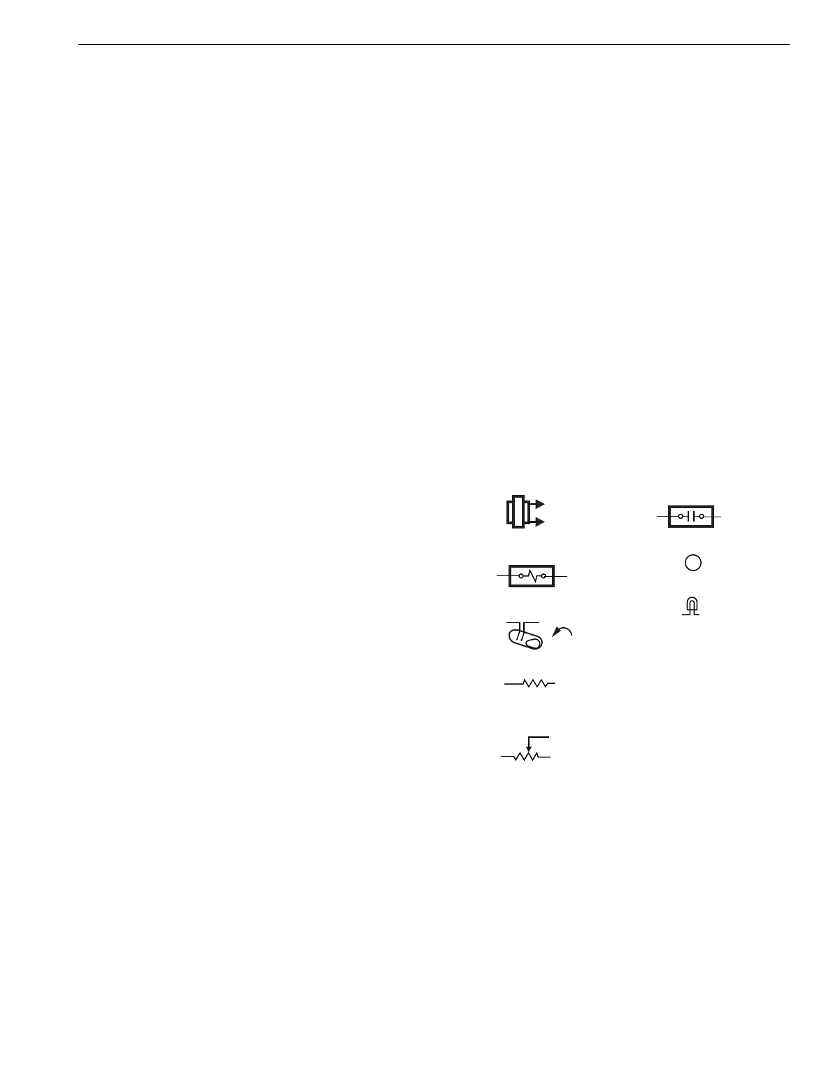
UNDERSTANDING CIRCUITS
To understand wirin
g
dia
g
rams, it is important to know what all
the s
y
mbols mean and how to trace the path of the circuits
from the transformer. See Fi
g
. 16 throu
g
h 25.
Circuit descriptions and terminolo
gy
are defined as follows:
For standard heatin
g
-coolin
g
circuits:
Auto chan
g
eover—refers to the presence of an AUTO
position in the s
y
stem switchin
g
(
EX: Q674E with OFF-
HEAT-AUTO-COOL switchin
g)
. The thermostat auto-
maticall
y
chan
g
es between heat and cool modes as
indoor temperature chan
g
es.
Manual chan
g
eover—re
q
uires a s
y
stem switch movement
to chan
g
e mode
(
EX: Q674B with HEAT-OFF-COOL
switchin
g)
. T874D Multista
g
e Thermostats with 2 heat
or 2 cool switches are shown on most standard circuits.
Most standard or TRADELINE® subbases
(
Q674A-E,G
)
can be used with T874A-F standard or TRADELINE
THERMISTOR RESISTANCE (ohms)
C815A THERMISTOR RESISTANCE
R = 400 ohms ± 10% AT 77°F (25°C)
4600
4400
4200
4000
3800
3600
3400
3200
3000
2800
2600
2400
2200
2000
1800
1600
1400
1200
1000
800
600
400
200
0-20 0 20 40 60 80 100 120 140
TEMPERATURE OF THERMISTOR
(
°F
)
M1590A
M5070
T874 MULTISTAGE THERMOSTATS AND Q674 SUBBASES
15 60-2485—8
thermostats. The schematics can be field-modified as
re
q
uired
(
EX: if T874C is bein
g
used, eliminate second
sta
g
e of heat
)
.
For heat pump circuits:
Cool chan
g
eover valve—operates on coolin
g
. The revers-
in
g
valve or rela
y
is activated either b
y
movin
g
the s
y
s-
tem switch to COOL
(
manual chan
g
eover
)
or b
y
a
mercur
y
switch that makes on a temperature rise
(
auto
chan
g
eover
)
.
Heat chan
g
eover valve—operates on heatin
g
. The revers-
in
g
valve or rela
y
is activated either b
y
movin
g
the s
y
s-
tem switch to HEAT
(
manual chan
g
eover
)
or b
y
a
mercur
y
switch that makes on a temperature fall
(
auto
chan
g
eover
)
.
S
y
stem monitor rela
y
—optional e
q
uipment on some heat
pumps includes an R4222P1065 or e
q
uivalent. This
s
y
stem monitor rela
y
detects a malfunction in the com-
pressor and indicates the malfunction b
y
activatin
g
the
EMERGENCY HEAT LED on the Q674 Switchin
g
Sub-
base. The s
y
stem monitor rela
y
is usuall
y
wired into the
L terminal on the Q674.
Each mercur
y
switch is identified b
y
function:
H1—Sta
g
e 1 Heatin
g
.
H2—Sta
g
e 2 Heatin
g
.
H3—Sta
g
e 3 Heatin
g
.
C1—Sta
g
e 1 Coolin
g
.
C2—Sta
g
e 2 Coolin
g
.
C3—Sta
g
e 3 Coolin
g
.
C/O—Chan
g
eover
(
heat pumps
)
.
Each anticipator is identified and each switch affected is
named
(
EX: H1 anticipator, C1 anticipator
)
.
All T874 Multista
g
e Thermostats use mercur
y
switches. Each
schematic indicates switch operation b
y
bein
g
drawn in the
open position with an arrow indicatin
g
operation with a
temperature RISE or FALL.
One circuit has been selected that is t
y
pical of various models
used with heat pumps. This circuit has been traced to
illustrate the functions performed b
y
these control s
y
stems.
Tracing Method:
1. Alwa
y
s be
g
in at the s
y
stem transformer or R terminal.
You ma
y
want to draw the switch contacts in each
switch position to aid in tracin
g
. Colored pencils are
helpful when onl
y
one cop
y
of the circuit is available.
See Fi
g
. 16 for a description of the hookup s
y
mbols and
Fi
g
. 17 throu
g
h 25 for t
y
pical hookups.
2. Completel
y
trace onl
y
one circuit at a time
(
for example:
heat or cool
)
.
3. Connections are indicated b
y
small dots at the point of
intersection. If there is no dot, there is no connection.
4. The left portion of the circuit
(
the thermostat
)
contains
the mercur
y
switches. The heat switches make on a
temperature fall, and the cool switches make on a tem-
perature rise. Fixed anticipation is represented b
y
a zi
g
-
za
g
line and ad
j
ustable anticipation is a zi
g
za
g
with an
arrow. The resistance of the fixed anticipator is so lar
g
e
it limits current so that a s
y
stem rela
y
cannot be pulled
in from a circuit path
g
oin
g
throu
g
h the fixed anticipator.
The rela
y
can be pulled in throu
g
h an ad
j
ustable antici-
pator because its resistance is
g
enerall
y
0 to 5 ohms.
5. The center portion
(
the subbase
)
contains the switches.
The fan switch is above the s
y
stem switch. The small
circles on the switch represent the maximum possible
contacts available on the Q674 Subbase. The lar
g
er cir-
cles represent the switch positions available on this par-
ticular Q674, with the solid circle representin
g
where it
is actuall
y
switched on the dia
g
ram.
NOTE: Solid circles are not interconnected electricall
y
.
At the ri
g
ht, the rela
y
s and contactors are shown, attached to
the proper terminals. The terminals are represented b
y
lar
g
e
circles with terminal desi
g
nations in capital letters. See Table
3 for the meanin
g
of each lettered terminal.
Sometimes power for a fixed anticipator is brou
g
ht throu
g
h an
off s
y
stem rela
y
like the chan
g
eover rela
y
shown in Fi
g
. 20.
This current is kept low b
y
the hi
g
h resistance of the fixed
anticipator so that rela
y
does not pull in.
Fig. 16. Key to hookup symbols.
M5848
KEY TO HOOKUP SYMBOLS
TRANSFORMER
(24 VAC SECONDARY)
RELAY/CONTACTOR CONTACTS
LED
RELAY OR CONTACTOR COIL
MERCURY SWITCH
FIXED ANTICIPATOR
HIGH RESISTANCE
(TYPICALLY 5 KILOHMS)
ADJUSTABLE ANTICIPATOR
LOW RESISTANCE
(TYPICALLY 0 TO 5 OHMS)
TERMINAL
ODT
OUTDOOR THERMOSTAT
EHR
EMERGENCY HEAT RELAY
RTD
TIME DELAY RELAY
RD
DEFROST RELAY
CHP
PRESSURE SWITCH
LACO
LOW AMBIENT CUTOFF
B
T874 MULTISTAGE THERMOSTATS AND Q674 SUBBASES
60-2485—816
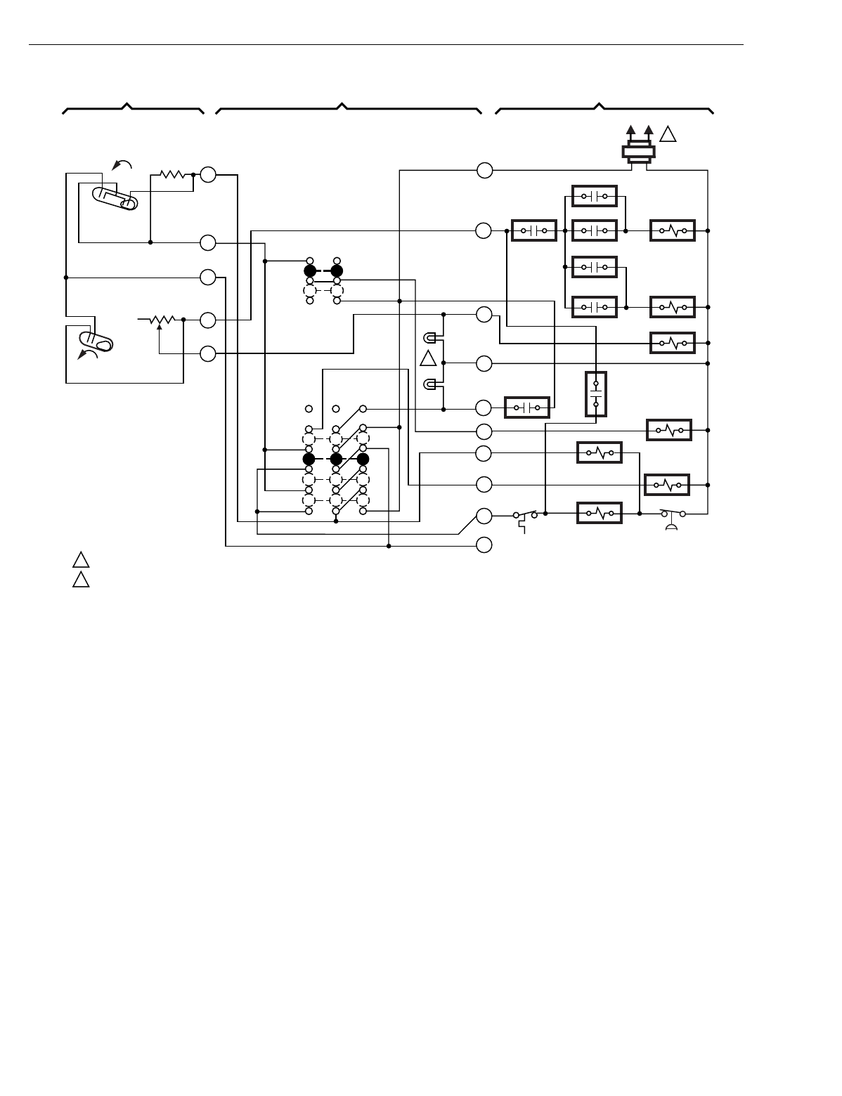
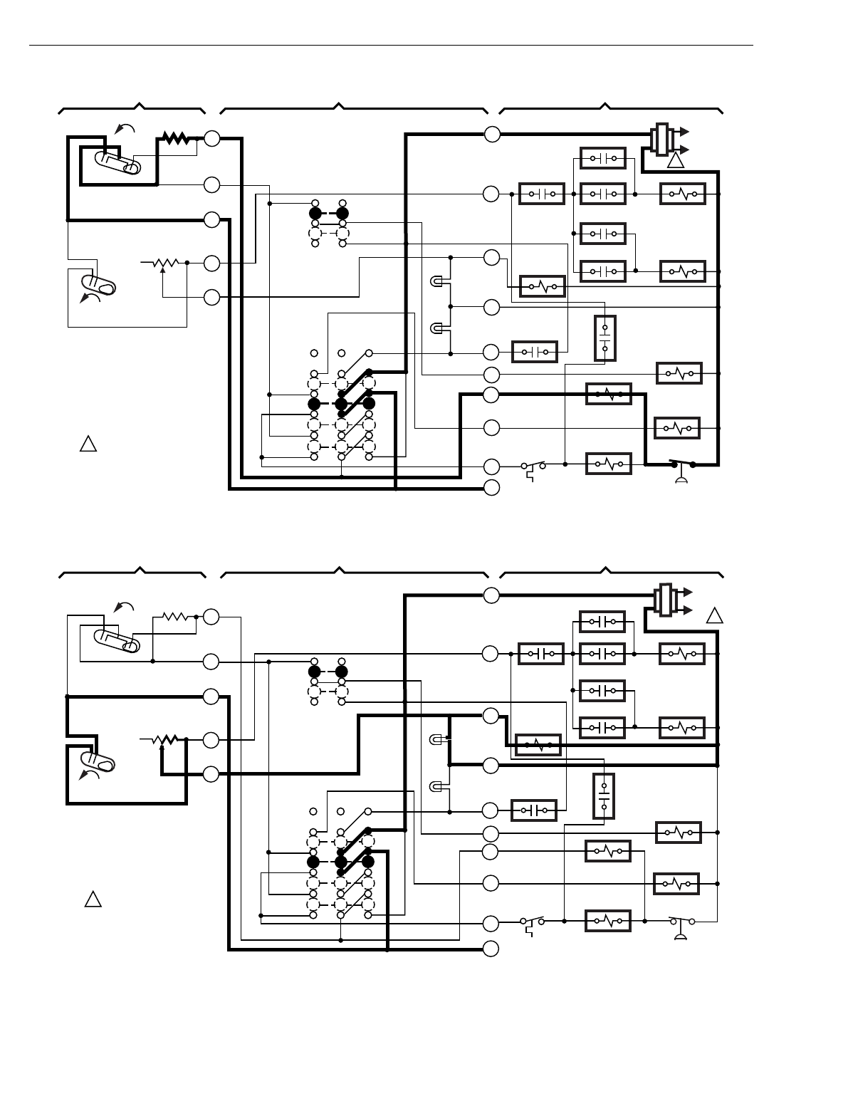
Fig. 17. Internal schematic and typical hookup of a T874R Thermostat and Q674L Subbase in a heat pump application.
The thermostat provides two-stage heating and one-stage cooling manual changeover operates on cooling.
M5072A
(HOT) L1 L2
1
LACO CHP
Y
B
E
O
G
L
X
W2
W3
RODT 1
RTD 1 EHR 1 RTD 2
ODT 2
EHR 2 RTD 3
RD
SYSTEM
MONITOR
FAN RELAY
COMPRESSOR
CONTACTOR
COOL CHANGEOVER
VALVE
EM. HT.
RELAY
RTD 1
AUX. HT.
LED
(GREEN)
EM. HT.
LED (RED)
FAN SWITCH
ON
AUTO
SYSTEM
SWITCH
EM. HT.
HEAT
OFF
COOL
H2
FALL
H1
FALL
C1
2
3
4
5
6
H1/C1
ANTICIPATOR
H2
ANTICIPATOR
1POWER SUPPLY. PROVIDE DISCONNECT MEANS AND OVERLOAD PROTECTION AS REQUIRED.
AUXILIARY HEAT LED AVAILABLE ON SOME MODELS.
THERMOSTAT SUBBASE SYSTEM COMPONENTS
2
2
T874 MULTISTAGE THERMOSTATS AND Q674 SUBBASES
17 60-2485—8
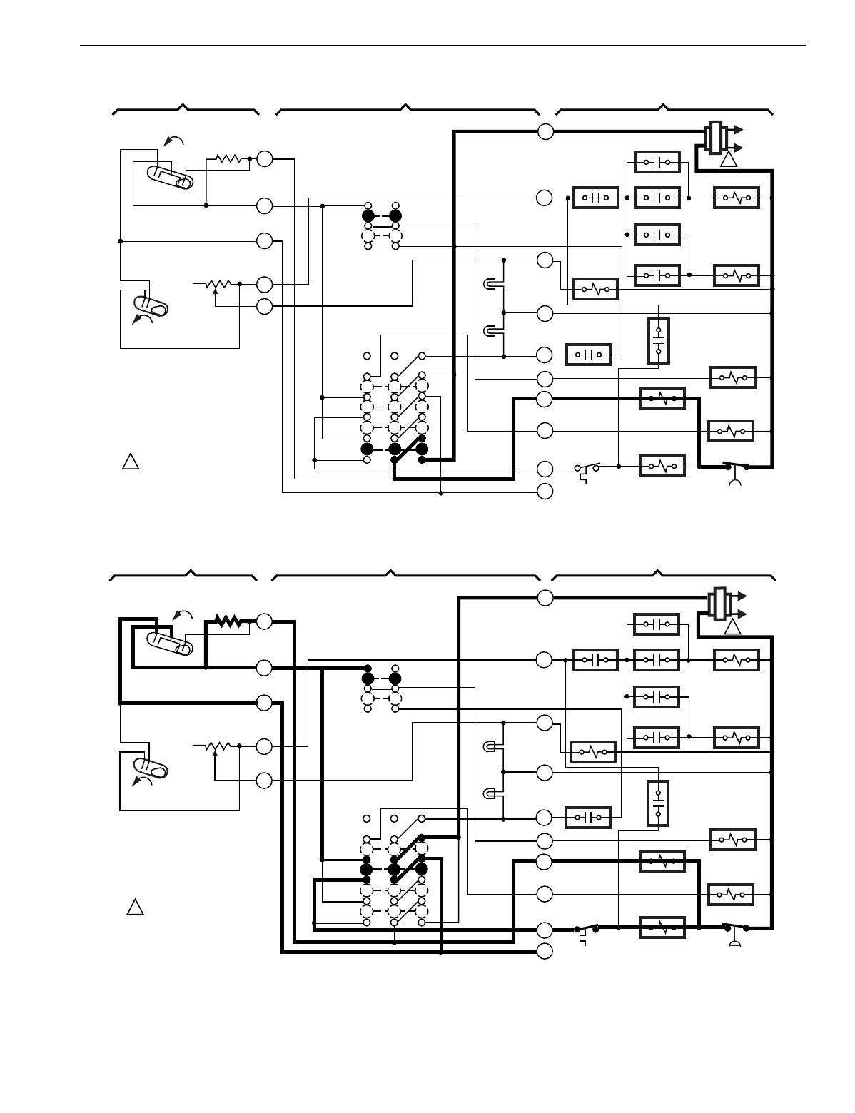
Fig. 18. Tracing the changeover relay circuit.
Fig. 19. Tracing the heat 1 and anticipation circuit.
M5840
L1
(HOT)
L2
1
LACO CHP
Y
B
E
O
G
L
X
W2
W3
R
ODT 1
RTD 1 EHR 1 RTD 2
ODT 2
EHR 2 RTD 3
RD
SYSTEM
MONITOR
FAN RELAY
COMPRESSOR
CONTACTOR
CHANGEOVER
VALVE
EM. HT.
RELAY
RTD 1
AUX. HT.
LED
(GREEN)
EM. HT.
LED (RED)
FAN SWITCH
ON
AUTO
SYSTEM
SWITCH
EM. HT.
HEAT
OFF
COOL
H2
FALL
H1
FALL
C1
2
3
4
5
6
H1/C1
ANTICIPATOR
H2
ANTICIPATOR
1POWER SUPPLY. PROVIDE
DISCONNECT MEANS AND
OVERLOAD PROTECTION
AS REQUIRED.
THERMOSTAT SUBBASE SYSTEM COMPONENTS
M5841
L1
(HOT)
L2
1
LACO CHP
Y
B
E
O
G
L
X
W2
W3
RODT 1
RTD 1 EHR 1 RTD 2
ODT 2
EHR 2 RTD 3
RD
SYSTEM
MONITOR
FAN RELAY
COMPRESSOR
CONTACTOR
CHANGEOVER
VALVE
EM. HT.
RELAY
RTD 1
AUX. HT.
LED
(GREEN)
EM. HT.
LED (RED)
FAN SWITCH
ON
AUTO
SYSTEM
SWITCH
EM. HT.
HEAT
OFF
COOL
H2
FALL
H1
FALL
C1
2
3
4
5
6
H1/ C1
ANTICIPATOR
H2
ANTICIPATOR
1POWER SUPPLY. PROVIDE
DISCONNECT MEANS AND
OVERLOAD PROTECTION
AS REQUIRED.
THERMOSTAT SUBBASE SYSTEM COMPONENTS
T874 MULTISTAGE THERMOSTATS AND Q674 SUBBASES
60-2485—818
Fig. 20. Tracing the heat 1 anticipation circuit.
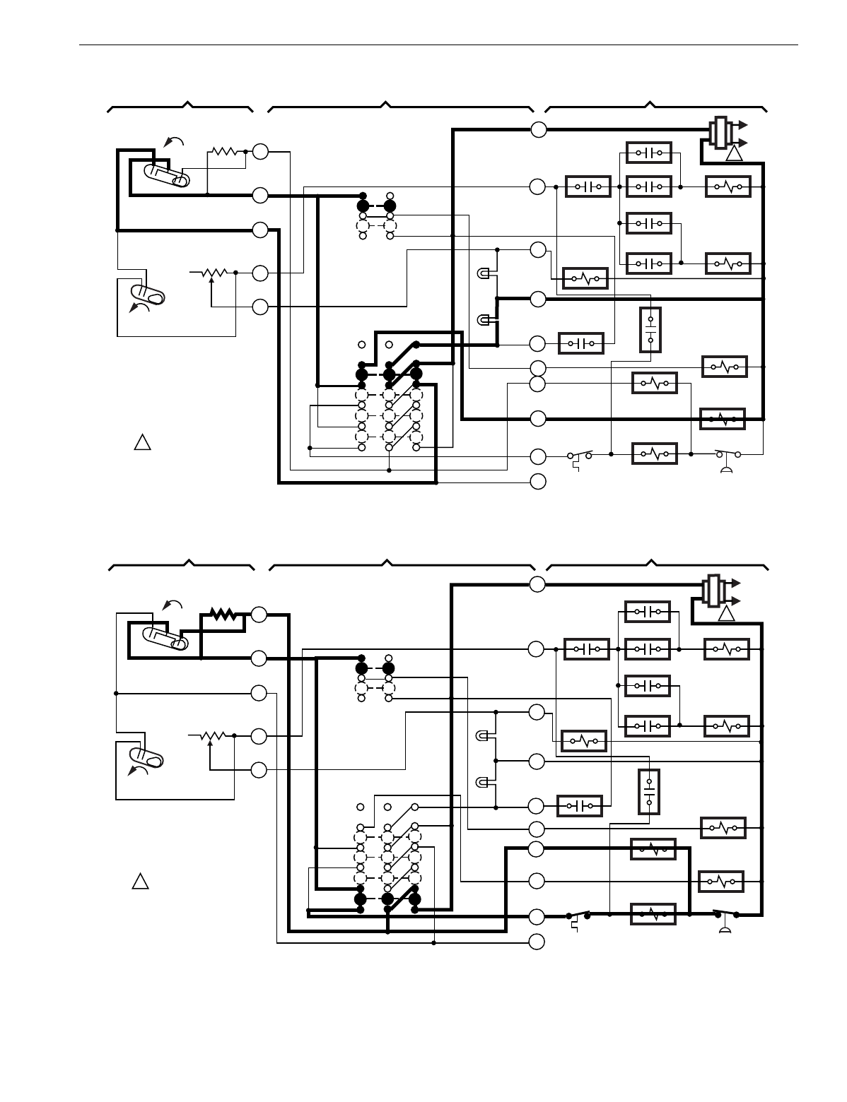
Fig. 21. Tracing the heat 2, anticipation and AUX. HT. LED circuit.
M5842
L1
(HOT)
L2
1
LACO CHP
Y
B
E
O
G
L
X
W2
W3
RODT 1
RTD 1 EHR 1 RTD 2
ODT 2
EHR 2 RTD 3
RD
SYSTEM
MONITOR
FAN RELAY
COMPRESSOR
CONTACTOR
CHANGEOVER
VALVE
EM. HT.
RELAY
RTD 1
AUX. HT.
LED
(GREEN)
EM. HT.
LED (RED)
FAN SWITCH
ON
AUTO
SYSTEM
SWITCH
EM. HT.
HEAT
OFF
COOL
H2
FALL
H1
FALL
C1
2
3
4
5
6
H1/ C1
ANTICIPATOR
H2
ANTICIPATOR
1POWER SUPPLY. PROVIDE
DISCONNECT MEANS AND
OVERLOAD PROTECTION
AS REQUIRED.
THERMOSTAT SUBBASE SYSTEM COMPONENTS
M5843
L1
(HOT)
L2 1
LACO CHP
Y
B
E
O
G
L
X
W2
W3
RODT 1
RTD 1 EHR 1 RTD 2
ODT 2
EHR 2 RTD 3
RD
SYSTEM
MONITOR
FAN RELAY
COMPRESSOR
CONTACTOR
CHANGEOVER
VALVE
EM. HT.
RELAY
RTD 1
AUX. HT.
LED
(GREEN)
EM. HT.
LED (RED)
FAN SWITCH
ON
AUTO
SYSTEM
SWITCH
EM. HT.
HEAT
OFF
COOL
H2
FALL
H1
FALL
C1
2
3
4
5
6
H1/C1
ANTICIPATOR
H2
ANTICIPATOR
1POWER SUPPLY. PROVIDE
DISCONNECT MEANS AND
OVERLOAD PROTECTION
AS REQUIRED.
THERMOSTAT SUBBASE SYSTEM COMPONENTS
T874 MULTISTAGE THERMOSTATS AND Q674 SUBBASES
19 60-2485—8
Fig. 22. Tracing the emergency heat and EM. HT. LED circuit.
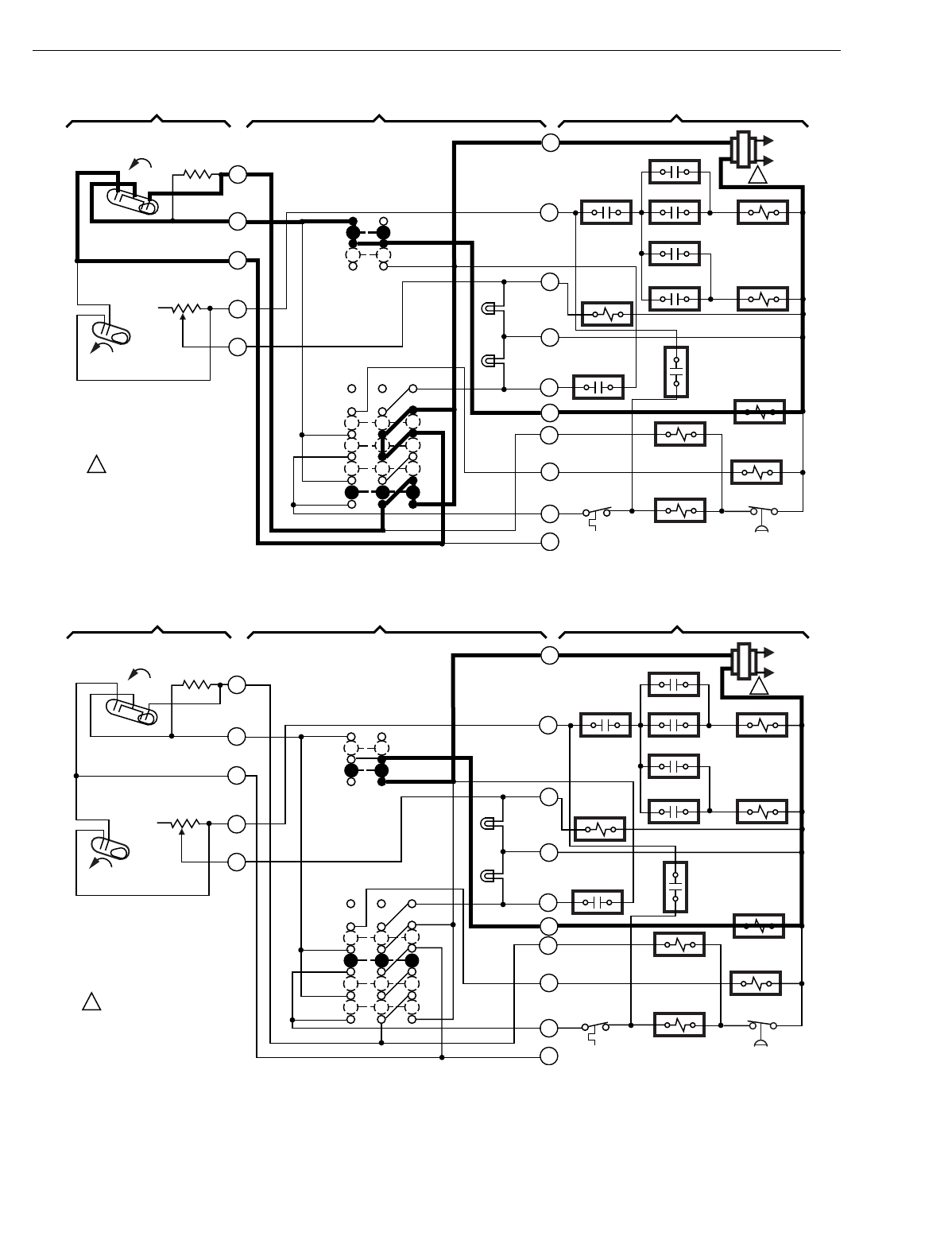
Fig. 23. Tracing the cooling circuit.
M5844
L1
(HOT)
L2
1
LACO CHP
Y
B
E
O
G
L
X
W2
W3
RODT 1
RTD 1 EHR 1 RTD 2
ODT 2
EHR 2 RTD 3
RD
SYSTEM
MONITOR
FAN RELAY
COMPRESSOR
CONTACTOR
CHANGEOVER
VALVE
EM. HT.
RELAY
RTD 1
AUX. HT.
LED
(GREEN)
EM. HT.
LED (RED)
FAN SWITCH
ON
AUTO
SYSTEM
SWITCH
EM. HT.
HEAT
OFF
COOL
H2
FALL
H1
FALL
C1
2
3
4
5
6
H1/C1
ANTICIPATOR
H2
ANTICIPATOR
1POWER SUPPLY. PROVIDE
DISCONNECT MEANS AND
OVERLOAD PROTECTION
AS REQUIRED.
THERMOSTAT SUBBASE SYSTEM COMPONENTS
M5845
L1
(HOT)
L2
1
LACO CHP
Y
B
E
O
G
L
X
W2
W3
R
ODT 1
RTD 1 EHR 1 RTD 2
ODT 2
EHR 2 RTD 3
RD
SYSTEM
MONITOR
FAN RELAY
COMPRESSOR
CONTACTOR
CHANGEOVER
VALVE
EM. HT.
RELAY
AUX. HT.
LED
(GREEN)
EM. HT.
LED (RED)
FAN SWITCH
ON
AUTO
SYSTEM
SWITCH
EM. HT.
HEAT
OFF
COOL
H2
FALL
H1
FALL
C1
2
3
4
5
6
H1/C1
ANTICIPATOR
H2
ANTICIPATOR
1POWER SUPPLY. PROVIDE
DISCONNECT MEANS AND
OVERLOAD PROTECTION
AS REQUIRED.
THERMOSTAT SUBBASE SYSTEM COMPONENTS
RTD 1
T874 MULTISTAGE THERMOSTATS AND Q674 SUBBASES
60-2485—820
Fig. 24. Tracing the auto fan circuit.
Fig. 25. Tracing the fan on circuit.
M5846
L1
(HOT)
L2
1
LACO CHP
Y
B
E
O
G
L
X
W2
W3
RODT 1
RTD 1 EHR 1 RTD 2
ODT 2
EHR 2 RTD 3
RD
SYSTEM
MONITOR
FAN RELAY
COMPRESSOR
CONTACTOR
CHANGEOVER
VALVE
EM. HT.
RELAY
RTD 1
AUX. HT.
LED
(GREEN)
EM. HT.
LED (RED)
FAN SWITCH
ON
AUTO
SYSTEM
SWITCH
EM. HT.
HEAT
OFF
COOL
H2
FALL
H1
FALL
C1
2
3
4
5
6
H1/C1
ANTICIPATOR
H2
ANTICIPATOR
1POWER SUPPLY. PROVIDE
DISCONNECT MEANS AND
OVERLOAD PROTECTION
AS REQUIRED.
THERMOSTAT SUBBASE SYSTEM COMPONENTS
M5847
L1
(HOT)
L2
1
LACO CHP
Y
B
E
O
G
L
X
W2
W3
RODT 1
RTD 1 EHR 1 RTD 2
ODT 2
EHR 2 RTD 3
RD
SYSTEM
MONITOR
FAN RELAY
COMPRESSOR
CONTACTOR
CHANGEOVER
VALVE
EM. HT.
RELAY
RTD 1
AUX. HT.
LED
(GREEN)
EM. HT.
LED (RED)
FAN SWITCH
ON
AUTO
SYSTEM
SWITCH
EM. HT.
HEAT
OFF
COOL
H2
FALL
H1
FALL
C1
2
3
4
5
6
H1/C1
ANTICIPATOR
H2
ANTICIPATOR
1POWER SUPPLY. PROVIDE
DISCONNECT MEANS AND
OVERLOAD PROTECTION
AS REQUIRED.
THERMOSTAT SUBBASE SYSTEM COMPONENTS
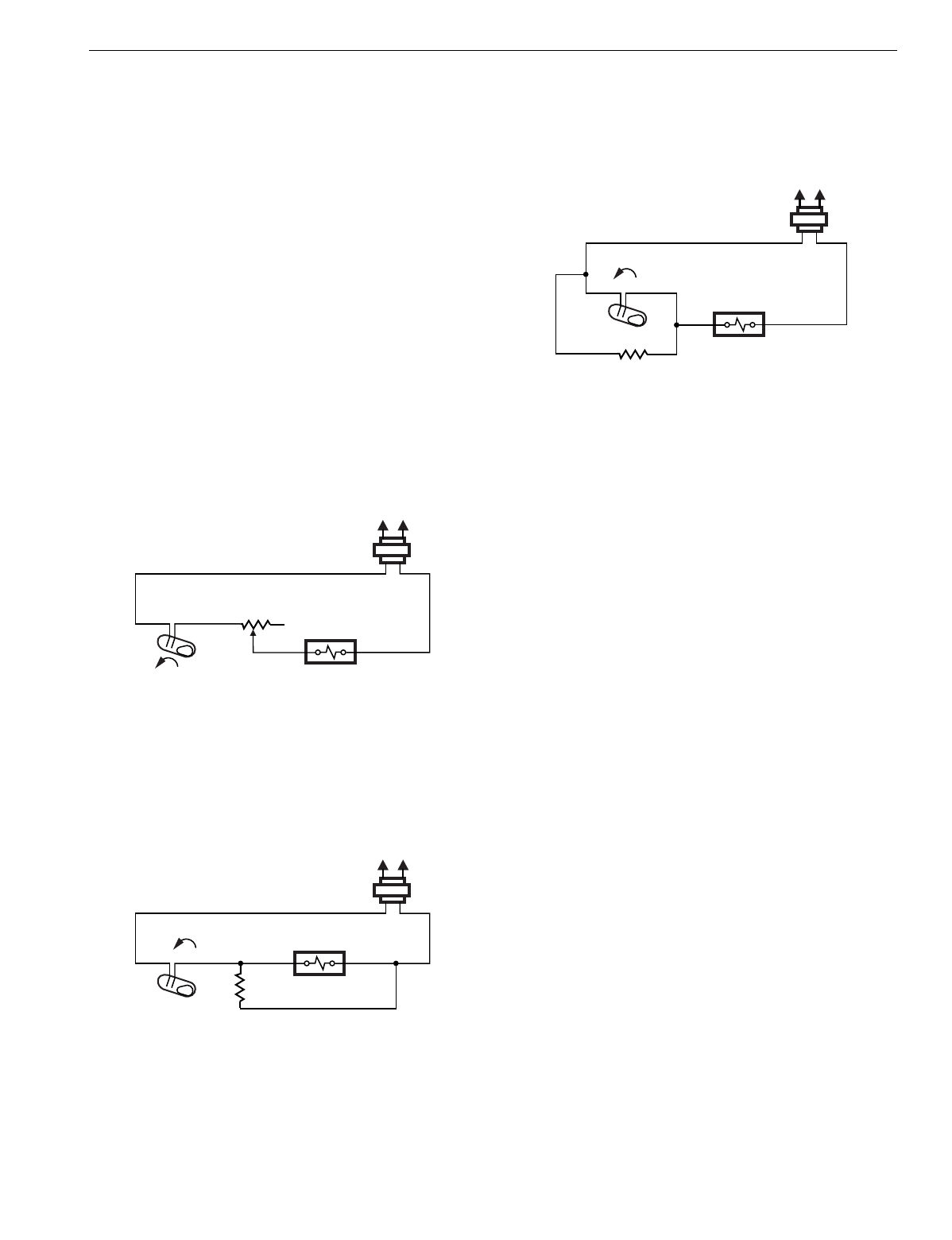
T874 MULTISTAGE THERMOSTATS AND Q674 SUBBASES
21 60-2485—8
OPERATION
Heat Anticipation/Cool Anticipation
When controllin
g
a heatin
g
unit with a thermostat, the
temperature does not remain exactl
y
at the thermostat
setpoint, but varies within a certain temperature ran
g
e. Heat
anticipation is added to the thermostat to reduce this ran
g
e.
The anticipator is a small resistive heater in the thermostat
that heats when the s
y
stem is on
(
heat mode
)
or off
(
cool
mode
)
. The heat produced b
y
the anticipator raises the
internal bimetal temperature sli
g
htl
y
faster than the
surroundin
g
room temperature. The thermostat
anticipates
the need to shut off the heatin
g
s
y
stem sooner than it would if
affected b
y
room temperature onl
y
.
There are two t
y
pes of heat anticipation, ad
j
ustable and fixed.
Ad
j
ustable anticipation is also called
current anticipation
. See
Fi
g
. 26. The heater is in series with the mercur
y
switch and
heatin
g
primar
y
. The pointer is ad
j
usted to match the current
draw of the primar
y
control, and the correct amount of heat is
added for proper c
y
cle rates.
Fig. 26. Adjustable anticipation heater in series with load.
Fixed anticipation is also called
voltage anticipation
. See
Fi
g
. 27. The heater is in parallel with the primar
y
control and is
not affected b
y
the current draw of the primar
y
. It establishes
the proper c
y
cle rate for an
y
application.
Fig. 27. Fixed anticipation heater in parallel with load.
Heat anticipators add heat durin
g
the call for heat. Coolin
g
anticipators are activated while the air conditioner is off. See
Fi
g
. 28. This heater makes the thermostat think it is warmer than
it reall
y
is, and brin
g
s it on sooner than the bimetal alone would.
Fig. 28. Internal cooling anticipation schematic.
Interstage Differential
The mercur
y
switch of each sta
g
e of heat makes at a sli
g
htl
y
different temperature; that is, the mercur
y
makes the contacts
of the first sta
g
e bulb at one temperature, and the second
sta
g
e bulb at another temperature. The difference between
these two temperatures is the
interstage differential
.
Intersta
g
e differential is the difference between the two make
points when the bulbs are controlled b
y
the heatin
g
of the
bimetal and the action of the heat anticipator. The intersta
g
e
differential is 1.9°F
(
1°C
)
between the sta
g
es of heatin
g
or the
sta
g
es of coolin
g
for most models.
Mechanical differential is the difference between the make
and break points of each switch. The mechanical differential
for the T874 is 1°F
(
0.6°C
)
between the sta
g
es of heatin
g
or
between the sta
g
es of coolin
g
for most models.
Droop
The addition of anticipator heat to the bimetal causes a control
factor called
droop
.
As the weather
g
rows colder, the heatin
g
appliance must
operate lon
g
er and more fre
q
uentl
y
. More heat must be added
to the bimetal. The bimetal now thinks it is warmer than it
reall
y
is, and actual room temperature is controlled at a lower
temperature than the setpoint indicates. At 100 percent heat
load, this droop can be si
g
nificant.
The C815A Outdoor Reset Thermistor is used in heat pump
s
y
stems to minimize droop. Without some method of
counterin
g
this situation, the occupant could notice the
temperature offset.
Outdoor Reset
Some T874/Q674 models are intended for use with the
C815A Outdoor Thermistor. The outdoor thermistor provides
si
g
nificantl
y
improved thermostat performance when
compared to conventional multista
g
e thermostats. The C815A
is usuall
y
located in the heat pump condensin
g
unit outdoors.
FALL
L1
(HOT) L2
M5823
STAGE 1 HEAT RELAY
H1 ANTICIPATOR
H1
FALL
L1
(HOT) L2
M5824
STAGE 1
HEAT RELAY
H1 ANTICIPATOR
H1
RISE
L1
(HOT) L2
M5825
STAGE 1
COOL RELAY
C1 ANTICIPATOR
C1
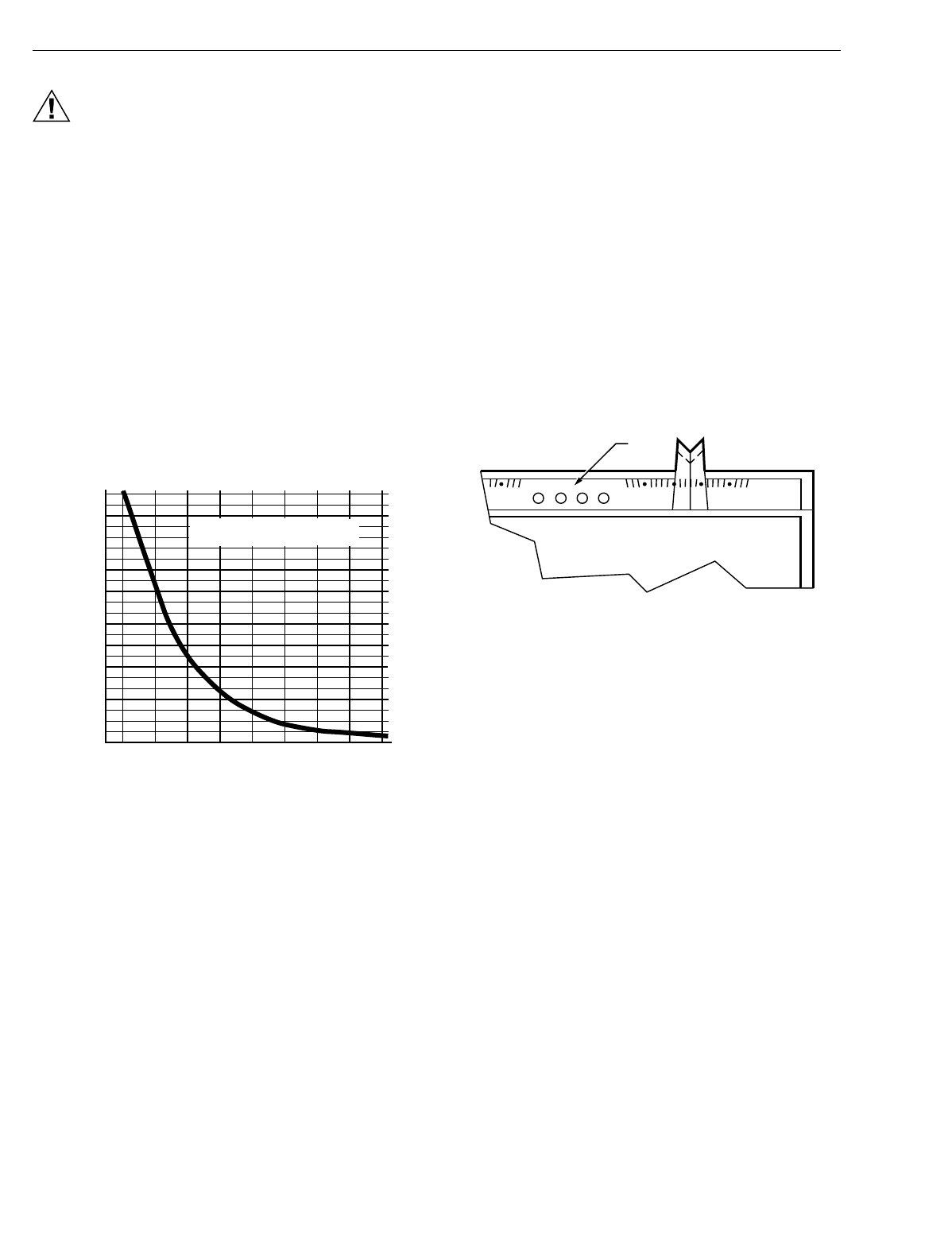
T874 MULTISTAGE THERMOSTATS AND Q674 SUBBASES
60-2485—822
CAUTION
Equipment Damage Hazard.
Due to calibration techni
q
ues used for T874
Thermostats with outdoor reset, the C815A Thermistor
must be wired into the s
y
stem at all times. Failure to
do so will result in serious de
g
radation of performance.
Service and Replacement of C815A Outdoor
Thermistor
To check and verif
y
thermistor operation, perform the
followin
g
steps:
1. Disconnect wire from T terminal on subbase.
2. Measure resistance with ohmmeter across the T sub-
base wire and X subbase terminal.
3. Take outdoor temperature measurement at thermistor
location and find correct thermistor resistance on the
chart in Fi
g
. 29.
4. Compare resistance on the chart with measured resis-
tance. Replace C815A if resistance varies more than 15
percent. Contact installin
g
dealer for packa
g
ed replace-
ment outdoor thermistor.
Fig. 29. Thermistor resistance chart.
Features
Two of the features of the T874/Q674 include LED indicators
and restricted setpoint.
LED Indicators
The li
g
ht-emittin
g
diodes
(
LED
)
indicators on the subbase
li
g
ht on command when somethin
g
specific happens in the
s
y
stem. See Fi
g
. 30.
Up to four different LEDs are available. The thermostat has a
clear lens window for viewin
g
each LED. On TRADELINE
models, a small insert is used so the LED function desired can
be selected.
This must be done during installation.
A blank insert is factor
y
-installed in some T874 models. To
remove it, push both temperature settin
g
levers to the far ends
of the thermostat. Use index fin
g
ernail to
g
entl
y
pull out the
scaleplate a fraction of an inch. Turn thermostat upside-down,
and the blank insert falls out.
A strip of four inserts is included with TRADELINE T874. Drop
a strip into the recessed area behind the scaleplate so
selected LEDs show. Make sure insert is completel
y
seated in
recessed area. Let scaleplate pop back; then set levers to
desired position.
•FILTER LED li
g
hts when the filter is clo
gg
ed and needs
replacement.
•CHECK LED li
g
hts when somethin
g
needs to be checked
or done to maintain efficient operation of s
y
stem. See
heatin
g
s
y
stem instructions for CHECK LED meanin
g
.
•EM. HT. LED li
g
hts when the emer
g
enc
y
heat is operatin
g
.
•SUPL. HT. LED li
g
hts when the supplemental heat is
operatin
g
.
•LOCKOUT LED li
g
hts when the s
y
stem is shut down and
needs maintenance.
•AUXILIARY HEAT LED li
g
hts when the auxiliar
y
heat is
operatin
g
.
•SERVICE or MALFUNCTION LED can have several
meanin
g
s. Consult heatin
g
s
y
stem instructions.
LEDs cannot be replaced or added in the field.
Fig. 30. T874/Q674 LED location.
Restricted Setpoint (DoD)
The Department of Defense
(
DoD
)
models are e
q
uipped with
a restricted setpoint feature for fuel efficienc
y
.
Fixed stops are factor
y
-set so setpoint levers cannot be set
above 72°F
(
22°C
)
on heatin
g
, or below 78°F
(
26°C
)
on coolin
g
.
Applications
The T874/Q674 can be applied to standard residential
s
y
stems for automatic or manual chan
g
eover, to commercial
rooftop applications, or to heat pump applications.
Changeover on Standard Residential
Systems
In a standard residential heatin
g
-coolin
g
circuit, chan
g
eover
between heatin
g
and coolin
g
can be done either automaticall
y
or manuall
y
.
Automatic chan
g
eover is done b
y
an AUTO position on the
subbase s
y
stem switch. See Fi
g
. 31. When the switch is in the
AUTO position, the thermostat automaticall
y
chan
g
es between
heat and cool modes, dependin
g
on the indoor temperature.
THERMISTOR RESISTANCE (ohms)
C815A THERMISTOR RESISTANCE
R = 400 ohms ± 10% AT 77°F (25°C)
4600
4400
4200
4000
3800
3600
3400
3200
3000
2800
2600
2400
2200
2000
1800
1600
1400
1200
1000
800
600
400
200
0-20 0 20 40 60 80 100 120 140
TEMPERATURE OF THERMISTOR (°F) M1590A
80 50 60 70 80 COOL
EM.
HEAT FILTER SERV. AUX
HEAT
M5830
LEDS
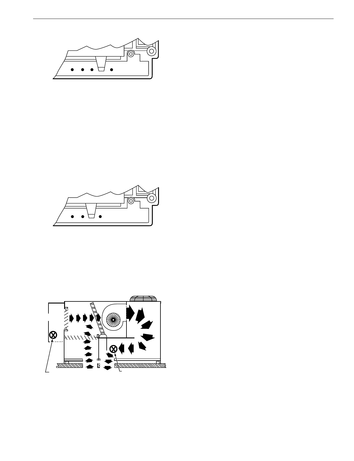
T874 MULTISTAGE THERMOSTATS AND Q674 SUBBASES
23 60-2485—8
Fig. 31. System switching for automatic changeover.
Automatic chan
g
eover is fre
q
uentl
y
used in areas where there
are lar
g
e temperature differences in 24 hours. Some uses for
the automatic chan
g
eover feature are in the southern states
(
cool in the mornin
g
and hot in the afternoon
)
and in
commercial applications.
Manual chan
g
eover re
q
uires a s
y
stem switch movement to
chan
g
e the mode. See Fi
g
. 32. Most manual chan
g
eover
switches consist of HEAT-OFF-COOL choices. For heatin
g
,
switch to HEAT. For coolin
g
, switch to COOL. It is not automatic.
Manual chan
g
eover is often used in areas where the
temperature is relativel
y
stable between da
y
and ni
g
ht.
Fig. 32. System switching for manual changeover.
Commercial Rooftop Application
The T874 can be used as part of a commercial rooftop
application to run mechanical coolin
g
.
An economizer is often used as part of a rooftop application to
save on air conditionin
g
. See Fi
g
. 33.
Fig. 33. Typical commercial rooftop economizer
application.
Enthalpy
is the temperature and humidit
y
of the air. A more
accurate anal
y
sis of the suitabilit
y
for free coolin
g
can be
made b
y
monitorin
g
the enthalp
y
.
When enthalp
y
is low enou
g
h, the thermostat and a sensor
tell the economizer damper to open to let in cool air from the
outside. When enthalp
y
is hi
g
h, the thermostat and sensor tell
the damper to close. No more outside air comes in, so the air
conditioner is used instead.
Heat Pump Application
A heat pump s
y
stem operates much like an air conditioner.
However, the heat pump is capable of movin
g
heat in two
directions; from inside the home to outdoors for coolin
g
, or
from outdoors to inside for heatin
g
.
The heat pump can be controlled b
y
separate rela
y
/contactor
components, which are ener
g
ized or de-ener
g
ized b
y
the T874.
Chan
g
eover between heatin
g
and coolin
g
for heat pump
circuits can be accomplished either manuall
y
or automaticall
y
.
Manual chan
g
eover control re
q
uires a s
y
stem switch
movement to chan
g
e the mode. The reversin
g
valve is
activated b
y
movin
g
the s
y
stem switch to COOL for coolin
g
or
to HEAT for heatin
g
operation.
Automatic chan
g
eover is accomplished b
y
one of the mercur
y
bulb switches in the thermostat. On a s
y
stem with automatic
chan
g
eover on coolin
g
, the chan
g
eover valve is ener
g
ized b
y
a mercur
y
switch that makes on a temperature rise. On
heatin
g
, the chan
g
eover valve is ener
g
ized b
y
a mercur
y
switch that makes on a temperature fall.
A description of the methods used to control heat pumps
follows.
Space Temperature Sensing Low Voltage
Controls
Control s
y
stems for heat pumps usuall
y
utilize low volta
g
e
control circuits. The variet
y
of control functions re
q
uired and
the relative complexit
y
re
q
uire a versatile and economical
method of control. There are several interlocks and indication
functions that would be more difficult and expensive to wire in
line volta
g
e circuits. Low volta
g
e controls have the precision
and flexibilit
y
needed.
The thermostat used is a low volta
g
e device that has
g
ood
temperature sensitivit
y
and several manual and automatic
switchin
g
capabilities.
Two-Stage Thermostat
In most installations, the heat pump itself re
q
uires auxiliar
y
heat, usuall
y
in the form of electric strip heaters, to carr
y
the
buildin
g
heatin
g
load at desi
g
n conditions. Since the heat
pump is usuall
y
more efficient, the control strate
gy
is to run
the heat pump
whenever possible
and the auxiliar
y
heat
only
when necessary—
durin
g
ver
y
cold weather or if the heat
pump fails. Usuall
y
the auxiliar
y
heat is used onl
y
below the
balance point
(
temperature at which the heat pump cannot
handle heatin
g
load b
y
itself
)
.
A two-sta
g
e thermostat makes this possible. The two sta
g
es
make
sequentially
as the temperature drops. There is a
de
g
ree or two between sta
g
es so that the second sta
g
e
(
the
OFF EM. HT. HEAT AUTO COOL
M5828
OFF EM. HT. HEAT COOL
M5829
M5827A
H205 OR H705
ENTHALPY
CONTROL
RETURN
AIR
DISCHARGE AIR SENSOR
DOWNSTREAM FROM THE
EVAPORATOR COIL
OUTDOOR
AIR
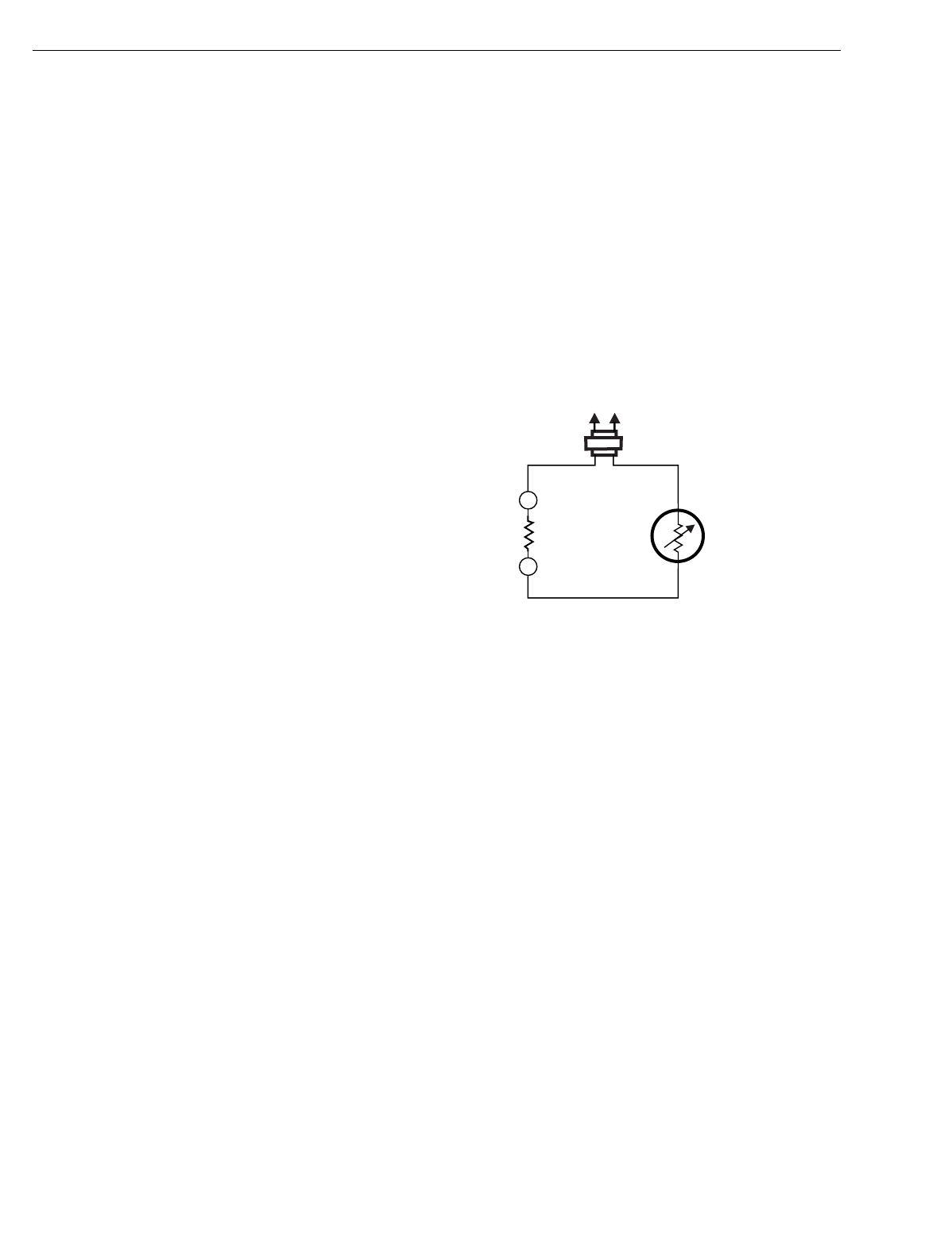
T874 MULTISTAGE THERMOSTATS AND Q674 SUBBASES
60-2485—824
one controllin
g
the auxiliar
y
heat
)
makes onl
y
when the heat
pump alone cannot handle the load. That is how the strate
gy
of usin
g
the most economical heat first is implemented.
Cycling Rate
Normall
y
, thermostat anticipation is set to c
y
cle a fossil fuel
furnace about five or six times an hour
(
at 50 percent load
)
.
This provides a reasonable balance between comfort, stabilit
y
and econom
y
.
A heat pump, bein
g
a mechanical refri
g
eration s
y
stem, should
be c
y
cled at a rate of 2-1/2 to 3 times an hour. With a T874,
this is accomplished b
y
settin
g
the anticipator at the total
current draw of the controlled device
(
the contactor and
possibl
y
the chan
g
eover rela
y
or valve
)
. Most likel
y
, the
compressor operates from the first sta
g
e of the thermostat.
The second sta
g
e normall
y
controls the auxiliar
y
heaters. This
heat anticipator can be set for the current draw of the electric
heat primar
y
, and produces
g
ood control.
Voltage Anticipation
Althou
g
h not a specific re
q
uirement for heat pumps, several
models of the T874 have volta
g
e heat anticipation instead of
current anticipation.
With volta
g
e anticipation, the amount of heat added to the
thermostat is constant no matter which load is connected to it.
The anticipator realizes a constant volta
g
e and produces a
constant amount of heat durin
g
the ON c
y
cle. This allows the
c
y
clin
g
rate to be
designed into
the thermostat. The heat
pump manufacturer is assured of correct performance
independent of later thermostat ad
j
ustments.
Outdoor Reset
Outdoor reset, which a C815A Outdoor Thermistor makes
possible, is sometimes applied in heat pump s
y
stems to help
minimize the effect of the differential between sta
g
es. It takes
2°F
(
1.1°C
)
chan
g
e in temperature to brin
g
on the second
sta
g
e and full heatin
g
. Added to a certain amount of droop
under hi
g
h loads, there can be a lar
g
e offset between the
setpoint and room temperature.
Without some method to counteract this situation, the
temperature offset from the setpoint could be as much as 6°F
(
3.3°C
)
under hi
g
h load conditions. It is not likel
y
that the
occupants accept this variation without makin
g
fre
q
uent
thermostat settin
g
chan
g
es.
Outdoor reset has the effect of raisin
g
the setpoint at cold
outdoor temperatures. Then, even with a few de
g
rees droop,
the space temperature sta
y
s near the desired settin
g
.
This is done b
y
calibratin
g
the thermostat hi
g
h b
y
5°F
(
3°C
)
—
the amount of expected offset. This offset compensates for
differential and droop at hi
g
h load factors so the thermostat
switches at the setpoint. At warm temperatures, heat is added
to the thermostat to compensate for this offset; at cold
temperatures, the extra heat is automaticall
y
removed. The
effect is the same as raisin
g
the setpoint as the outdoor
temperature
g
oes down.
This is particularl
y
important on the 3-sta
g
e T874. The
additional sta
g
e means that more droop is introduced when
the s
y
stem is in operation. That is the reason the TRADELINE
T874W is sold in a packa
g
e with the outdoor sensor and the
correct subbase.
Outdoor Reset—How it Works
The heater in the thermostat is connected in series with a
thermistor sensor that measures outdoor temperature. See
Fi
g
. 34. In warm weather, the thermistor has ver
y
low
resistance, permittin
g
a lar
g
e current flow in the heater, which
g
enerates a relativel
y
lar
g
e amount of heat in the thermostat.
In cold weather, the outdoor sensor has hi
g
h resistance,
which results in low current flow and little or no heat bein
g
added to the thermostat. This raises the control point,
overcomin
g
the effects of droop and intersta
g
e differential.
Fig. 34. Location of thermistor.
Changeover
Chan
g
eover between heatin
g
and cooin
g
can be
accomplished either
automatically
or
manually
, dependin
g
on
the application. Chan
g
eover can occur in heatin
g
or coolin
g
.
The chan
g
eover valve is ener
g
ized as lon
g
as the subbase
function switch is in the appropriate position when
manual
chan
g
eover is used. If a s
y
stem manuall
y
chan
g
es over on
coolin
g
, the valve ener
g
izes whenever the subbase switch is
in the coolin
g
mode.
One of the mercur
y
bulb switches is used for control when the
thermostat has
automatic
chan
g
eover. When the
automatic
chan
g
eover is in coolin
g
, the chan
g
eover valve is ener
g
ized
when the first sta
g
e coolin
g
switch makes. The second sta
g
e
switch turns on the compressor.
It is more common with new e
q
uipment to find that
chan
g
eover occurs with coolin
g
; that is, the chan
g
eover valve
is ener
g
ized to produce coolin
g
.
Whether
automatic
or
manual
chan
g
eover is used and
whether the reversin
g
valve is ener
g
ized with coolin
g
or with
heatin
g
, a heat pump s
y
stem can be controlled b
y
the
appropriate T874 Multista
g
e Thermostat.
L1
(HOT)
L2
RESET
HEATER
C815A
OUTDOOR
THERMISTOR
SENSOR
M5826
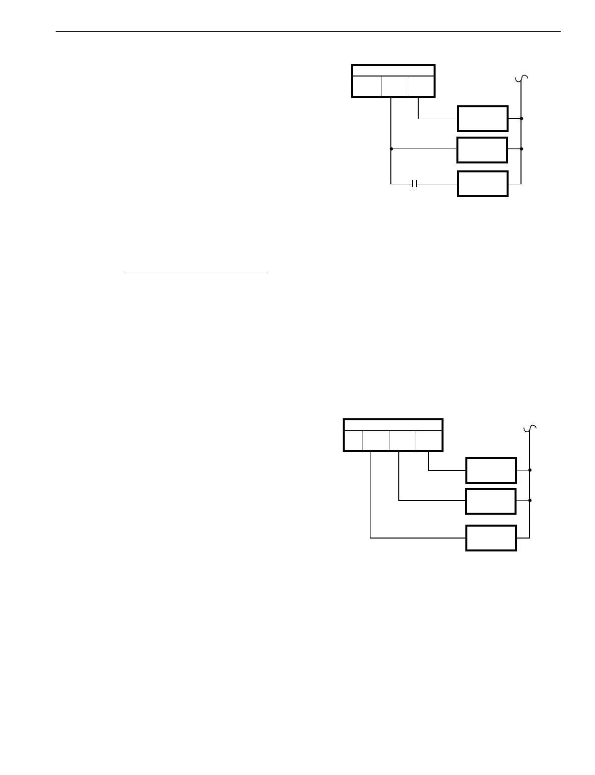
T874 MULTISTAGE THERMOSTATS AND Q674 SUBBASES
25 60-2485—8
Low Temperature Lockouts
Some manufacturers of heat pumps have previousl
y
controlled
their units so the compressor was locked out below a specified
outdoor temperature. This was done because of the stress
placed on the compressor b
y
the ver
y
cold temperatures, and
the fact that efficienc
y
drops off at low temperatures.
Other manufacturers sa
y
that althou
g
h efficienc
y
is low at cold
temperatures, the problem of startin
g
the cold compressor is
the most critical point. It is more important to keep the
compressor runnin
g
than to shut it off and tr
y
to restart it when
the temperature warms up to +10°F
(
-12°C
)
. Also the
crankcase heater, which can run onl
y
when the compressor is
off, compensates for the lower compressor efficienc
y
. So, it is
e
q
uitable to let the heat pump run even with a coefficient of
performance
(
COP
)
sli
g
htl
y
less than one, rather than to turn it
off and have to run the crankcase heater.
NOTE: To determine the COP of a heat pump, use the fol-
lowin
g
formula:
COP = Btu Out/Btu we pa
y
for or Btuh Capacit
y
Unit Watta
g
e x 3.413 Btu/Watt
Another factor favorin
g
this control strate
gy
is that newer heat
pump desi
g
ns maintain a level of efficienc
y
even at outdoor
temperatures well below zero. Some brands do not reach
1.0 COP until -25°F
(
-32°C
)
.
Virtuall
y
all manufacturers now let the heat pump run
continuousl
y
rather than lock it out at cold temperatures.
Heat Pumps with Dual Compressors
Sta
g
in
g
residential sized heat pumps is a re
q
uirement that
developed from the need to make heat pumps as efficient as
possible. One of the methods used to improve overall
seasonal efficienc
y
is to reduce the amount of time the
machine is operatin
g
in a transitional mode. Transitional mode
is startin
g
and stoppin
g
in addition to recoverin
g
from defrost.
Under li
g
ht loads, when the heat pump is c
y
clin
g
on and off,
this can be a si
g
nificant amount of time and can result in a
si
g
nificant efficienc
y
reduction. Capacit
y
control is one wa
y
to
reduce the c
y
clin
g
rate and improve the efficienc
y
.
Additional capacit
y
control methods used on other
refri
g
eration s
y
stems
(
unloadin
g
, multiple compressors
)
are
not as likel
y
to be seen on residential heat pumps.
With a sin
g
le-sta
g
e heat pump, the compressor is normall
y
controlled b
y
the first sta
g
e and the auxiliar
y
heat b
y
the
second sta
g
e. The T874G, N and R Thermostats are used for
this purpose.
With a two-sta
g
e compressor, the two thermostat switches
control the individual compressor sta
g
es. Auxiliar
y
heat is
controlled alon
g
with the compressor sta
g
e-two, b
y
the
thermostat second sta
g
e. It comes on with the compressor
hi
g
h speed if an outdoor thermostat—wired in series with it—
is made. See Fi
g
. 35.
Fig. 35. Two-stage heat pump with two-stage thermostat.
The outdoor thermostat is set at the balance point with both
heat pump sta
g
es runnin
g
. So if the heat pump can control the
heatin
g
load down to +20°F
(
-7°C
)
, the auxiliar
y
heat comes
on with the second sta
g
e of the compressor.
In effect, this control strate
gy
chan
g
es the heat input of the
second sta
g
e, dependin
g
on the amount of heat needed.
Additional sta
g
es of auxiliar
y
heat can be added with or
without the control of more outdoor thermostats, See Auxiliar
y
Heat section.
Another wa
y
to control a two sta
g
e heat pump is with a three-
sta
g
e thermostat. The T874W is desi
g
ned for this application
as well as others. See Fi
g
. 36.
The advantage of this system is that no auxiliary heat is used
until there is an actual demand from the controlled space.
Fig. 36. Two-stage heat pump with three-stage
thermostat.
Two speed Heat Pump
One wa
y
to control capacit
y
is to use a two-speed
compressor. The compressor runs at low speed for sta
g
e-one
heatin
g
and coolin
g
. The compressor runs at the low speed
instead of c
y
clin
g
the heat pump on and off under some li
g
ht
load conditions.
The hi
g
h speed is sta
g
e-two coolin
g
. The compressor runs on
hi
g
h speed when loads increase so the low speed can no
lon
g
er handle the coolin
g
load. This reduces c
y
clin
g
rate and
improves capacit
y
.
M5838
THERMOSTAT
HEAT 2 HEAT 1
OUTDOOR
THERMOSTAT
COMP.
STAGE 2
AUXILIARY
HEAT
COMP.
STAGE 1
M5837
COMP.
STAGE 2
THERMOSTAT
HEAT 2 HEAT 1
AUXILIARY
HEAT
HEAT 3
COMP.
STAGE 1
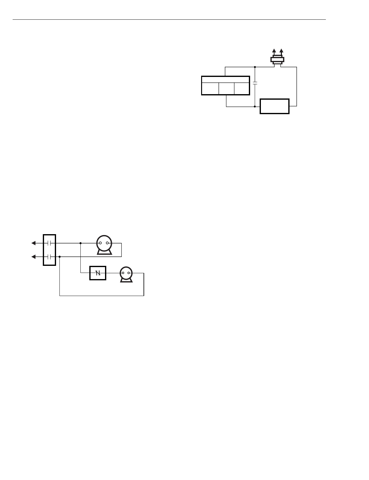
T874 MULTISTAGE THERMOSTATS AND Q674 SUBBASES
60-2485—826
Defrost Control
In some re
g
ions, durin
g
half or more of the heatin
g
season,
the outdoor coil operates below 32°F
(
0°C
)
Frost or ice builds
up on the outdoor coil of a heat pump similarl
y
to the frost
buildup in a household refri
g
erator. Eventuall
y
, this
accumulation of ice interferes with efficient heat transfer from
the outdoor air to the coil and refri
g
erant. Defrostin
g
is
occasionall
y
re
q
uired to remove this ice, and restore the heat
pump abilit
y
to absorb heat from the air.
Defrosting
A heat pump defrosts its outdoor coil b
y
temporaril
y
switchin
g
to the coolin
g
mode, which causes hot
g
as from the
compressor to be directed to the outdoor coil instead of to the
indoor coil so the heat pump is takin
g
heat from the home to
warm up the outdoor coil. Defrostin
g
is the
g
reatest detriment
to heat pump efficienc
y
.
Defrost Control Functions
Besides chan
g
in
g
over to the coolin
g
mode, defrostin
g
re
q
uires several more control initiated actions that follow.
OUTDOOR FAN
When defrostin
g
has be
g
un, it is standard practice to turn off
the outdoor fan to speed up the meltin
g
process. A separate
defrost rela
y
is re
q
uired to control that fan. See Fi
g
. 37. Other
contacts can be needed on the defrost rela
y
to power the
chan
g
eover valve or power part of the auxiliar
y
heat.
Fig. 37. Outdoor fan with defrost control.
AUXILIARY HEAT DURING DEFROST
Most pump manufacturers brin
g
on some auxiliar
y
heat durin
g
defrost, althou
g
h this is not a universal practice. Some rel
y
on
the second sta
g
e of the thermostat to call for auxiliar
y
heat as
needed. Since the heat pump is operatin
g
in the coolin
g
mode
to defrost, it is deliverin
g
cold air to the livin
g
space. Auxiliar
y
heat is used to offset this coolin
g
. It re
q
uires another normall
y
open contact on the defrost rela
y
. See Fi
g
. 38.
Fig. 38. Auxiliary heat with defrost control.
WHEN TO DEFROST
Timel
y
defrostin
g
is an essential component of effective heat
pump operation. Failure to defrost often enou
g
h permits too
much ice to accumulate on the coil. At the ver
y
least, this
hurts efficienc
y
; at worst, it results in compressor dama
g
e.
Insufficient defrostin
g
is a condition the heat pump
manufacturer wants ver
y
much to avoid.
A 50 percent reduction in outdoor airflow is the maximum that
would be tolerated. So the desi
g
ner of a heat pump would
select a control point that puts the s
y
stem into defrost when
airflow throu
g
h the outdoor coil approaches half its normal
level. Restricted airflow causes a
g
reater load on the
compressor; the outdoor coil runs colder, suction pressure is
lower and the motor runs hotter.
At the other end of the scale, defrostin
g
too often hurts the
overall ener
gy
efficienc
y
of the s
y
stem. Consider that in terms
of heatin
g
the buildin
g
, defrostin
g
is a bi
g
loss. Not onl
y
does
the s
y
stem stop heatin
g
, but it actuall
y
moves heat out of the
buildin
g
. If electric strip heat is used, it is a further waste
because its COP is 1.0 and not the 2.0 or more COP realized
if the heat is provided b
y
the heat pump.
So, concern for e
quipment safety
su
gg
ests fairl
y
fre
q
uent
defrostin
g
while
economy of operation
ar
g
ues for fewer
defrost c
y
cles. Since the e
q
uipment manufacturer chooses, the
balance is usuall
y
tipped in favor of more fre
q
uent defrostin
g
to
avoid the possibilit
y
of dama
g
in
g
the compressor.
Auxiliary Heat
Except in warm climates, all air-to-air heat pump installations
re
q
uire auxiliar
y
heat capabilit
y
. Electric resistance heaters
can provide this auxiliar
y
heat.
The electric heaters
(
sometimes called strip heaters
)
usuall
y
are supplied in 5 kW units or strips
(
about 17,000 Btu
)
. The
indoor unit of the heat pump is desi
g
ned to accommodate
various electric heat units so it can be used in variousl
y
sized
buildin
g
s in different parts of the countr
y
.
Two-Stage Thermostat
The most common heat pump control strate
gy
is for the
thermostat first sta
g
e to switch the compressor and the
second sta
g
e to switch the auxiliar
y
heat. See Fi
g
. 39.
M5839
COMPRESSOR
MOTOR
CONTACTOR
CONTROLLED BY
DEFROST RELAY OUTDOOR
FAN MOTOR
M5835
THERMOSTAT
HEAT 2 HEAT 1
DEFROST
RELAY
CONTACT
AUXILIARY
HEAT RELAY
L1
(HOT)
L2
TRANSFORMER
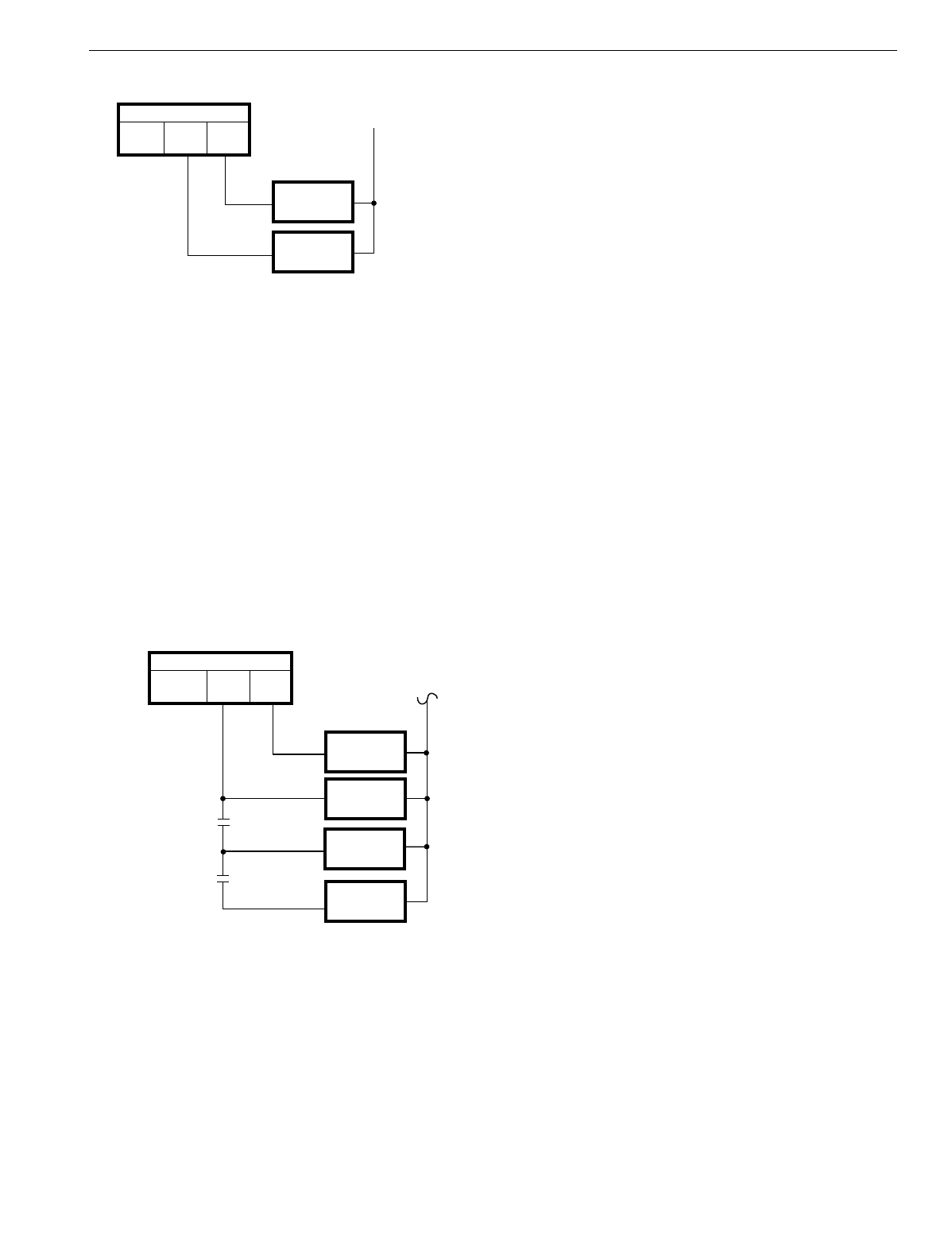
T874 MULTISTAGE THERMOSTATS AND Q674 SUBBASES
27 60-2485—8
Fig. 39. Auxiliary heat in two-stage thermostat.
This method keeps the auxiliar
y
heat off until the heatin
g
load
is lar
g
e enou
g
h to demand 100 percent heat pump operation.
That demand is measured b
y
the thermostat and is the actual
heat re
q
uirement of the space. The two-sta
g
e thermostat
re
q
uires about a 2°F
(
1.1°C
)
room temperature drop to brin
g
on the second sta
g
e.
Stage or Time Modulated Control
There are two different wa
y
s to control auxiliar
y
heat, sta
g
ed
or time modulated control.
Outdoor thermostats
are used to switch additional increments
of electric heat into the thermostat circuit as the outdoor
temperature
g
ets lower. All increments of auxiliar
y
heat are
still controlled b
y
sta
g
e-two of the thermostat but onl
y
if the
outdoor temperature re
q
uires the additional capacit
y
. See
Fi
g
. 40.
Fig. 40. Outdoor thermostats for auxiliary heat.
The rationale for this s
y
stem is that it ver
y
closel
y
matches the
s
y
stem capacit
y
to the heatin
g
load of the buildin
g
. B
y
calculatin
g
the heat loss of a buildin
g
, the installin
g
contractor
can pick the theoretical outdoor temperature at which to
permit each additional unit of electric heat to be operated b
y
the second sta
g
e of the room thermostat.
The disadvanta
g
e of this s
y
stem is that it can re
q
uire several
outdoor thermostats. Also, since the unit is operatin
g
most
often at nearl
y
full capacit
y
, the thermostat is on lon
g
er which
results in more droop, with a little more offset from the
thermostat setpoint.
In addition, the capacit
y
is tied to theoretical load, based on heat
loss calculations. Normall
y
this is ver
y
close to the actual load,
but there are times where the second sta
g
e is switched on too
soon
(
no harm done
)
or too late
(
the buildin
g
g
ets cold
)
.
The T874 Thermostat produces
time modulated
control, which
is the on time of the thermostat chan
g
in
g
durin
g
each c
y
cle as
the load chan
g
es. The on time of the heatin
g
s
y
stem is
directl
y
proportional to the heatin
g
load of the buildin
g
. As an
example of the
q
ualit
y
of time modulated control, consider the
t
y
pical
g
as furnace. It can have a capacit
y
of 100,000 Btu
(
293 kW
)
, which is controlled On-Off. The output is 100,000 Btu
(
293 kW
)
or nothin
g
. A
q
ualit
y
thermostat controls so closel
y
that
the occupants rarel
y
detect chan
g
es in room temperature.
The same is true with 50,000 or 60,000 Btu
(
146.5 or
178.8 kW
)
of heat pump auxiliar
y
electric heat. The T874 can
provide the same hi
g
h
q
ualit
y
control.
This scheme also eliminates the need for outdoor thermostats
and thus offers the manufacturer an opportunit
y
to reduce unit
cost. One disadvanta
g
e is that a
thermostat jiggler
can be
demandin
g
more kW of strip heat when chill
y
.
The method an
y
particular manufacturer selects depends on
which ar
g
uments it finds persuasive and the opinions of its
distributors and dealers.
Three-Stage Thermostat
A definite improvement in
q
ualit
y
of control and econom
y
can
be achieved with a three-sta
g
e thermostat
(
T874W
)
, which is
especiall
y
true with heat pumps usin
g
dual compressors.
Three-sta
g
e control permits both the heat pump and the
auxiliar
y
heat to be tied directl
y
to the demand of the
controlled space. With a two-sta
g
e compressor, maximum
(
100 percent
)
heat pump operation is re
q
uired before auxiliar
y
heat is brou
g
ht on.
Emergency Heat
Some provision is
g
enerall
y
re
q
uired to back up the compressor
in the event of a failure durin
g
the heatin
g
season. In fact, it is
q
uite common to find that local buildin
g
codes or electric utilities
re
q
uire that a specified percent of the buildin
g
heatin
g
re
q
uirements be available from emer
g
enc
y
heat—a source
other than the heat pump compressor. Almost universall
y
, the
source is electric resistance heaters. T
y
picall
y
, the re
q
uirement
is for 70 or 80 percent of the buildin
g
heatin
g
needs.
Switching to Emergency Heat
Conventional heat pump control
(
thermostat lo
g
ic
)
usuall
y
includes a manual subbase switch to brin
g
on the emer
g
enc
y
heat.
In one control strate
gy
, the
emergency heat
rela
y
is turned on
b
y
the EM.HT. selector switch on the thermostat subbase. The
compressor is prevented from runnin
g
. The electric heaters
are c
y
cled as the
y
normall
y
would be b
y
the
second stage
of
M5836
COMPRESSOR
CONTRACTOR
THERMOSTAT
HEAT 2 HEAT 1
AUXILIARY
HEAT RELAY
CONTROLS
AT 65°F (18°C)
CONTROLS
AT 63°F (17°C)
M5834
COMPRESSOR
CONTACTOR
THERMOSTAT
HEAT 2 HEAT 1
AUXILIARY
HEAT RELAY 1
AUXILIARY
HEAT RELAY 2
AUXILIARY
HEAT RELAY 3
OUTDOOR
THERMOSTATS
20°F
(-7°C)
5°F
(-15°C)
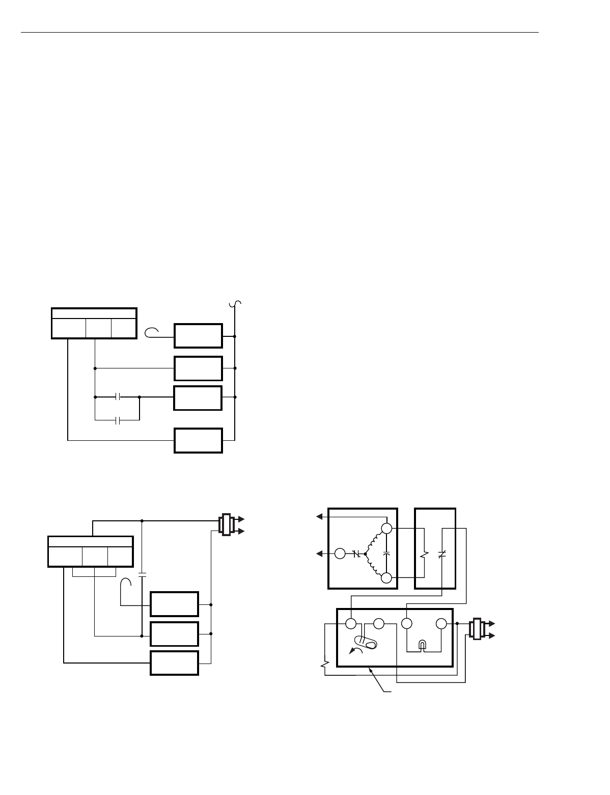
T874 MULTISTAGE THERMOSTATS AND Q674 SUBBASES
60-2485—828
the thermostat. A set of contacts on the emer
g
enc
y
heat rela
y
is used to b
y
pass each outdoor thermostat so that all electric
heat is under immediate thermostat sta
g
e-two control. So the
emer
g
enc
y
heat rela
y
simpl
y
b
y
passes the outdoor
thermostats. See Fi
g
. 41.
In the
second
method, the emer
g
enc
y
heat relay is cycled
directl
y
b
y
the thermostat mercur
y
bulb. In this hookup, the
rela
y
is controlled b
y
the thermostat
first stage
. The
emer
g
enc
y
heat rela
y
ener
g
izes all of the auxiliar
y
heat rela
y
s
on a call for heat. See Fi
g
. 42.
So the emer
g
enc
y
heat is controlled b
y
the first sta
g
e of the
thermostat. The emer
g
enc
y
heat rela
y
ener
g
izes all of the
electric strip heaters so the heat and the indoor fan come on
to
g
ether as soon as the first sta
g
e calls for heat.
With the first method, the fan remains on
(
bein
g
controlled b
y
the first sta
g
e of the thermostat
)
and the electric heaters c
y
cle
on and off with the second sta
g
e.
In either case, a subbase indicator li
g
ht is turned on whenever
the function switch is in the emer
g
enc
y
heat
(
EM.HT.
)
position.
Fig. 41. Emergency heat relay that bypasses
the outdoor thermostats.
Fig. 42. Emergency heat relay that energizes all of the
auxiliary heat relays on a call for heat.
Crankcase Heat
In an
y
mechanical refri
g
eration s
y
stem, refri
g
erant tends to
mi
g
rate to the coldest part of the e
q
uipment and condense
there. In a heat pump, this coldest spot could be the compressor
because it is usuall
y
outdoors. In addition, the oil in the com-
pressor crankcase is capable of absorbin
g
a hi
g
h concentration
of refri
g
erant. On compressor startup, there are two risks:
(
1
)
the
li
q
uid refri
g
erant, which is noncompressible, can be drawn into
the c
y
linder, and
(
2
)
considerable oil can be entrained in the
refri
g
erant and swept out of the crankcase throu
g
h the
chan
g
eover valve and dispersed in the pipin
g
and coils.
So the mi
g
ration of refri
g
erant to the crankcase is undesirable
because it can interfere with s
y
stem lubrication and because the
li
q
uid refri
g
erant must be kept from
g
oin
g
throu
g
h the compressor.
Addin
g
a crankcase heater creates enou
g
h temperature
differential to prevent this mi
g
ration because the compressor
is no lon
g
er the coldest part of the s
y
stem so refri
g
erant does
not mi
g
rate to it.
Compressor Fault Relay
Another ver
y
simple method of detectin
g
a compressor failure
has been developed. It uses the volta
g
e developed across the
capacitor in a permanent split capacitor compressor motor.
The principle involved is that virtuall
y
all serious problems
reduce the volta
g
e across the motor capacitor. B
y
carefull
y
selectin
g
the correct coil volta
g
e, the normall
y
closed rela
y
does not pull in unless the proper volta
g
e builds up across the
capacitor, which brin
g
s on the SERVICE LED. See Fi
g
. 43.
Here is how it works:
•On a call for coolin
g
, the thermostat makes R to Y, the
contactor coil is powered, and the compressor motor turns on.
•At the same time, the indicator li
g
ht is ener
g
ized.
•As the motor
g
ets up to speed—about one second, the
fault rela
y
sees enou
g
h volta
g
e to pull in. Its normall
y
closed contact opens and the indicator li
g
ht
g
oes out.
•An
y
thin
g
that prevents the motor from runnin
g
prevents the
fault rela
y
from pullin
g
in.
Fig. 43. Compressor fault relay schematic.
M5833
COMPRESSOR
THERMOSTAT
FUNCTION
SWITCH HEAT 2 HEAT 1
EMERGENCY HEAT
RELAY CONTACT EMERGENCY
HEAT RELAY
AUXILIARY
HEAT RELAY 1
AUXILIARY
HEAT RELAY 2
OUTDOOR
THERMOSTAT
M5832
COMPRESSOR
THERMOSTAT
FUNCTION
SWITCH HEAT 2 HEAT 1
EMERGENCY
HEAT RELAY
CONTACT
24 V
EMERGENCY
HEAT RELAY
AUXILIARY
HEAT RELAY
RISE
L1
(HOT)
L2
M5831
COMPRESSOR MOTOR FAULT RELAY
YRLX
LED
CAP.
RUN
START S
R
C
L1
L3
CONTACTOR THERMOSTAT-
SUBBASE
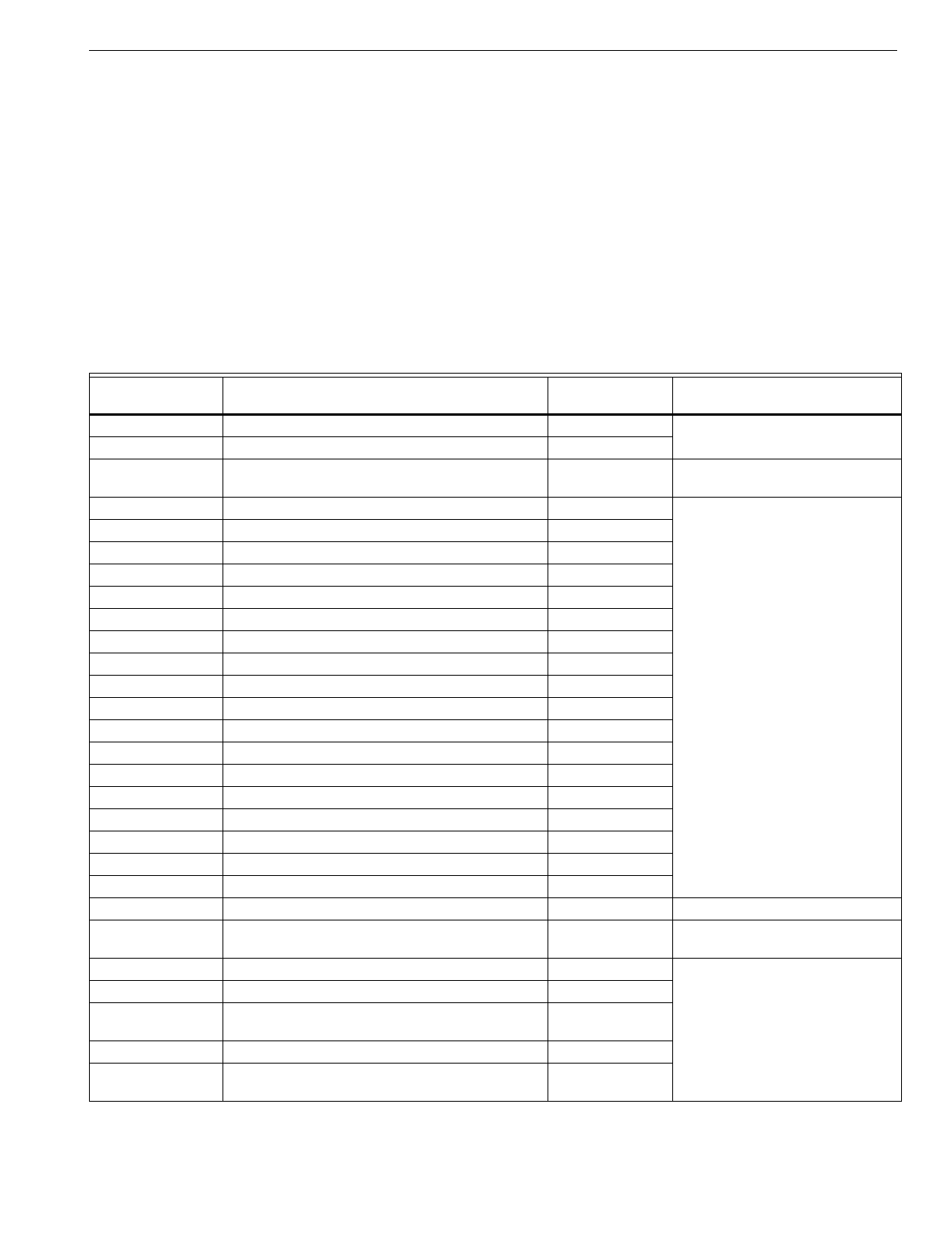
T874 MULTISTAGE THERMOSTATS AND Q674 SUBBASES
29 60-2485—8
CROSS REFERENCE
The followin
g
section lists the current T874 Trade replace-
ments for T872 and T874 Multista
g
e Thermostats. It also lists
the Q674 Trade replacements for Q672 and Q674 Subbases.
All thermostats listed carr
y
the Hone
y
well lo
g
o unless
otherwise noted.
When usin
g
the Cross Reference Charts, refer to the followin
g
instructions:
1. Locate and identif
y
the existin
g
thermostat and subbase
model.
2. Refer to the Model Number column to find the model
that matches the existin
g
thermostat and subbase.
3. The Description column identifies certain characteristics
of the existin
g
device.
4. The Trade Replacement column identifies the correct
replacement device.
5. The Remarks column lists an
y
characteristics or ad
j
ust-
ments to be made on the Trade replacement model.
6. The Fig. No. column lists the wirin
g
hookup used for the
specific model number. The wirin
g
dia
g
rams follow the
Cross Reference section.
7. Refer to the circuit illustration that corresponds with the
appropriate number. This fi
g
ure illustrates the internal
electric circuit for the desired model number.
Table 6. T872-T874 Thermostat Cross Reference.
Model Number Description T874 Trade
ReplacementaRemarks
T872A 1-sta
g
e heat, 1-sta
g
e cool
A1006 Standard OEM T874A1036
A1014 72-78°F
(
22-26°C
)
stop; lockin
g
cover; no
thermometer T874A1010 Use T874A1176 for Dept. of
Defense
(
DoD
)
application.
A1022 Heat anticipator set at 0.45A T874A1036
A1030 0.4A heat anticipator settin
g
T874A1036
A1048 TRADELINE T874A1036
A1055 AAF lo
g
o; lockin
g
cover T874A1036
A1063 Climatrol lo
g
o T874A1036
A1071 Lennox lo
g
o; 0.5A heat anticipator settin
g
T874A1036
A1089 Melco lo
g
o T874A1036
A1097 Westin
g
house lo
g
o T874A1036
A1105 Amana lo
g
o; 1.2A heat anticipator settin
g
T874A1036
A1113 Trane lo
g
o T874A1036
A1121 Airtemp
(
Chr
y
sler
)
lo
g
o T874A1036
A1139 Sin
g
er lo
g
o; no. 02005384 T874A1036
A1147 American Standard lo
g
o T874A1036
A1154 Carrier lo
g
o and color; no. HH07AT074 T874A1036
A1162 General Electric lo
g
o; no. AY28X097 T874A1036
A1170 Sears lo
g
o; no. 4291441 T874A1036
A1188 Command-Aire lo
g
o T874A1036
A1196 Sin
g
er lo
g
o; Celsius scale; no. 02005521 T874A1036
A1204 Carteret lo
g
o T874A1036
A1212 General Electric; no. AY28X114; 72-78°F
(
22-26°C
)
stop T874A1010 Use T874A1176 for Dept. of
Defense
(
DoD
)
application.
A1220 Sin
g
er lo
g
o; no. 050240-01 T874A1036
A1238 Celsius scale T874A1036
A1246 TRADELINE; lockin
g
cover and ad
j
ustable lockin
g
lever stops T874A1150
A1253 Trane Comfort Corp T874A1036
A1261 TRADELINE; 72-78°F
(
22-26°C
)
stop; lockin
g
cover; no thermometer; meets DoD specs T874A1176
aWhen replacin
g
a T872 Thermostat and Q672 Subbase, alwa
y
s replace both the thermostat and the subbase.
T874 MULTISTAGE THERMOSTATS AND Q674 SUBBASES
60-2485—830
A1279 General Electric lo
g
o; no. AY28X114A; 75°F stop;
lockin
g
cover; no thermometer. T874A1010 Use T874A1176 for Dept. of
Defense
(
DoD
)
application.
A1287 General Electric; no. AY28X097A; fan current
shunt for auto fan in heatin
g
; heat anticipator set at
0.4A.
T874A1036/
Q674B1018 Set thermostat sta
g
e 1 heat
anticipator for total of fan and sta
g
e
1 primar
y
control current draw.
A1295 Lennox; Celsius scale T874A1036
A1303 Lennox lo
g
o; no. 64A0601; meets DoD specs T874A1176
A1311 Envirotron special; Celsius scale T874A1010
A1329 Carrier lo
g
o; Celsius scale; no. HH07AT074C T874A1036
A1337 S
q
uare D; no. HCD-3; heat anticipator set at 0.2A T874A1036
A1345 TRADELINE; Celsius scale T874A1010
A1352 Heat anticipator set 1.2A T874A1036
A1360 Friedrich lo
g
o; heat anticipator set at 0.2A T874A1036
A1378 Wesco lo
g
o; heat anticipator set at 0.8A T874A1036
T872B 1-sta
g
e heat, 2-sta
g
e cool
B1005 Standard OEM T874B1019
B1013 0.4A heat anticipator settin
g
T874B1019
B1021 TRADELINE T874B1019
B1039 Westin
g
house lo
g
o T874B1019
B1047 American Standard lo
g
o T874B1019
B1054 Climatrol lo
g
o T874B1019
B1062 Carrier lo
g
o T874B1019
B1070 Trane lo
g
o T874B1019
B1088 Fedders lo
g
o T874B1019
B1096 Climatrol lo
g
o T874B1019
B1104 Carteret lo
g
o T874B1019
B1112 Sin
g
er lo
g
o; no. 050240-03 T874B1019
B1120 Celsius scale T874B1019
B1138 Sin
g
er lo
g
o; no. 02005711; lockin
g
cover and
lever. T874B1019
B1146 Lennox lo
g
o; no. P-8-8895 T874B1019
B1153 Lennox lo
g
o; Celsius scale T874B1019
T872C 2-sta
g
e heat, 1-sta
g
e cool
C1004 Standard OEM T874C1018
C1012 Heat anticipator set at 0.4A T874C1018
C1020 72-78°F
(
22-26°C
)
stop; lockin
g
cover; no
thermometer; 42-88°F
(
6-31°C
)
setpoint ran
g
e. T874C1141 Use T874C1141 for Dept. of
Defense
(
DoD
)
application.
C1038 TRADELINE T874C1018
C1046 American Standard lo
g
o T874C1018
C1053 Friedrich lo
g
o T874C1018
C1061 Lennox lo
g
o; no. P-8-8896 T874C1018
C1079 Westin
g
house lo
g
o; sta
g
e 1 heat anticipator set at
0.75A; sta
g
e 2 anticipator set at 1.2A T874C1018
C1087 Fast c
y
cle performance on both heat sta
g
es;
anticipator ran
g
e 0.12-0.6A T874C1018 Ad
j
ust anticipator
faster
for correct
performance.
C1095 Pa
y
ne lo
g
o; no. 0.1-0.175 T874C1018
Table 6. T872-T874 Thermostat Cross Reference.
Model Number Description T874 Trade
ReplacementaRemarks
aWhen replacin
g
a T872 Thermostat and Q672 Subbase, alwa
y
s replace both the thermostat and the subbase.
T874 MULTISTAGE THERMOSTATS AND Q674 SUBBASES
31 60-2485—8
C1103 Amana lo
g
o; anticipator set at 1.2A T874C1018
C1111 Airtemp
(
Chr
y
sler
)
lo
g
o T874C1018
C1129 Da
y
and Ni
g
ht lo
g
o; no. 0.1-0.174 T874C1018
C1137 Fast c
y
cle performance on both heat sta
g
es T874C1018 Ad
j
ust anticipator
faster
for correct
performance.
C1145 Rheem lo
g
o T874C1018
C1152 Ruud lo
g
o T874C1018
C1160 Climatrol lo
g
o T874C1018
C1178 Wesco lo
g
o T874C1018
C1186 Sears lo
g
o T874C1018
C1194 First Co. lo
g
o T874C1018
C1202 Carrier lo
g
o T874C1018
C1210 Carrier lo
g
o; Celsius scale T874C1018
C1228 0.4A heat anticipator settin
g
T874C1018
C1236 Carrier lo
g
o; no. HH07AT070 T874C1018
C1244 Fraser-Johnson lo
g
o T874C1018
C1251 Trane lo
g
o T874C1018
C1269 Fedders lo
g
o T874C1018
C1277 Climatrol special T874C1018
C1285 Auto
g
as lo
g
o T874C1018
C1293 Fedders lo
g
o T874C1018
C1301 Climatrol lo
g
o T874C1018
C1319 Command-Aire lo
g
o T874C1018
C1327 Melco lo
g
o; lock cover and levers T874C1018
C1335 Sin
g
er lo
g
o
(
Carteret
)
T874C1018
C1343 Sin
g
er lo
g
o; no. 050240-04 T874C1018
C1350 Celsius scale T874C1018
C1368 12°F
(
67°C
)
differential between heat 1 and
heat 2 T874C1125
C1376 AAF lo
g
o; lockin
g
cover; 72-78°F
(
22-26°C
)
stop T874C1018
C1384 Servel lo
g
o T874C1018
C1392 TRADELINE; fast c
y
cle performance on both heat
sta
g
es. T874C1018 Ad
j
ust anticipator
faster
for correct
performance.
C1400 72-78°F
(
22-26°C
)
stop; lockin
g
cover; no
thermometer; meets DoD specs T874C1141
C1418 Solaron lo
g
o T874C1018
C1426 Lennox lo
g
o; no. 42C04; four LEDs None
C1434 Carrier lo
g
o; no. HH07AT070C; Celsius scale T874C1018
C1442 Goettl lo
g
o T874C1018
C1459 Goettl lo
g
o; used with Q672N1001, N1019 None
C1467 Lennox lo
g
o; Celsius scale T874C1018
C1475 Tappan lo
g
o; no. 080-13708-37 T874C1018
C1483 Fasco lo
g
o; no. 1230-8161 T874C1018
C1491 Lennox lo
g
o; no. 64A0501; lockin
g
cover; no
thermometer; meets DoD specs T874C1141
Table 6. T872-T874 Thermostat Cross Reference.
Model Number Description T874 Trade
ReplacementaRemarks
aWhen replacin
g
a T872 Thermostat and Q672 Subbase, alwa
y
s replace both the thermostat and the subbase.
T874 MULTISTAGE THERMOSTATS AND Q674 SUBBASES
60-2485—832
C1509 Fedders lo
g
o; used with Q672L1102 Y594R1425 Wirin
g
differences
(
old=new
)
: C=X,
K=E; remove Y-W1
j
umper.
C1517 Climatrol lo
g
o; used with Q672L1102 Y594R1425 Wirin
g
differences
(
old=new
)
: C=X,
K=E; remove Y-W1
j
umper.
C1525 S
q
uare D lo
g
o; no. HCD-2 T874C1018
C1533 Airtemp lo
g
o T874C1018
C1541 Airtemp lo
g
o; used with Q672L1102 Y594R1425 Wirin
g
differences
(
old=new
)
: C=X,
K=E; remove Y-W1
j
umper.
C1566 TRADELINE; Celsius scale T874C1018 Replacement has °F scaleplate.
C1574 Whalen special; used with Q672B1269 None
C1582 Lennox; meets DoD None
C1590 Sin
g
er; 8°F
(
4.4°C
)
differential between sta
g
e
1 and sta
g
e 2 T874C1125 Replacement has 2°F
(
1° C
)
differential between H1 and H2.
C1608 Sin
g
er lo
g
o; no. 02005784 8°F
(
4.4°C
)
differential
between sta
g
e 1 and sta
g
e 2 T874C1125 Replacement has 2°F
(
1°C
)
differential between H1 and H2.
C1616 Celsius scale; stop set at 23°C None Add 4074ECK ad
j
ustable stop.
C1624 Heat Wave lo
g
o; no. 0360-116 T874C1018
C1632 York lo
g
o; heat anticipator set at 0.2A T874C1018
C1640 Heat anticipator set at 0.4A T874C1018
C1665 Wesco lo
g
o; heat anticipator set at 0.8A T874C1018
C1673 Wards lo
g
o; used with Q672B1285, B1293 Gas s
y
stems:
T874C1018/
Q674B1034
Electric s
y
stems:
T874C1018/
Q674B1075
Ad
j
ust anticipator faster for correct
performance.
C1681 Lechauffa
g
e Urbain lo
g
o; Celsius scale T874C1018
C1699 Duotherm lo
g
o; used with Q672E1068 or
Q672F1000 T874C1018 See subbase description for
replacement information.
C1707 Si
g
ler lo
g
o; used with Q672N1027 None
C1715 Westin
g
house lo
g
o T874C1018
T872D 2-sta
g
e heat, 2-sta
g
e cool
D1003 Standard OEM T874D1165
D1011 TRADELINE T874D1165
D1029 Westin
g
house lo
g
o T874D1165
D1037 Climatrol lo
g
o T874D1165
D1045 Lennox lo
g
o; no. P-8-8897; used with Q672E1191. T874D1165
D1052 York lo
g
o T874D1165
D1060 Sin
g
er lo
g
o; no. 02005385 T874D1165
D1078 Rheem lo
g
o T874D1165
D1086 Rudd lo
g
o T874D1165
D1094 York lo
g
o; lockin
g
cover T874D1165
D1102 American Standard lo
g
o T874D1165
D1110 ITT lo
g
o T874D1165
D1128 Carrier lo
g
o T874D1165
D1136 No anticipator on sta
g
e 1 cool; used with
Q672C1029 T874D1165
Table 6. T872-T874 Thermostat Cross Reference.
Model Number Description T874 Trade
ReplacementaRemarks
aWhen replacin
g
a T872 Thermostat and Q672 Subbase, alwa
y
s replace both the thermostat and the subbase.
T874 MULTISTAGE THERMOSTATS AND Q674 SUBBASES
33 60-2485—8
D1144 Carrier lo
g
o; no. HH07AT072 T874D1165
D1151 General Electric lo
g
o; no. AY28X098; 0.4 heat
anticipator settin
g
T874D1165
D1169 Airtemp
(
Chr
y
sler
)
lo
g
o; used with Q672E1118 T874D1165/
Q674E1049 Wirin
g
differences
(
old=new
)
:
A=W1; set H1 anticipator to 1.2A.
D1177 Trane lo
g
o T874D1165
D1185 Dunham-Bush lo
g
o T874D1165
D1193 Fedders lo
g
o T874D1165
D1201 Climatrol lo
g
o T874D1165
D1219 Command-Aire lo
g
o T874D1165
D1227 Sin
g
er lo
g
o; no. 02005522; Celsius scale T874D1165
D1235 Sin
g
er lo
g
o;
(
Carteret
)
T874D1165
D1243 Friedrich lo
g
o T874D1165
D1250 Sin
g
er lo
g
o; no. 050240-02 T874D1165
D1268 Airtemp lo
g
o T874D1165
D1276 Celsius scale T874D1165
D1284 Solaron T874D1165
D1292 Tok
y
o Carrier lo
g
o; no. HH07AT072C; Celsius
scale T874D1165
D1300 SUPER TRADELINE T874D1165
D1318 General Electric lo
g
o; no. AY28X098A; fan current
shunt for auto fan in heatin
g
.T874D1165/
Q674B1075
D1326 General Electric lo
g
o; lockin
g
cover 72-78°F
(
22-26°C
)
stop; fan current shunt for auto fan in
heatin
g
.
T874D1165
D1334 Lennox lo
g
o; Celsius scale T874D1165
D1342 Tappan lo
g
o; no. 080-13708-32 T874D1165
D1359 Sin
g
er lo
g
o; no. 02005740; Celsius scale; 6.6°C
differential between H1 and H2. T874D1165 Onl
y
2°F
(
1°C
)
differential between
H1 and H2.
D1367 Friedrich lo
g
o; no. 600-580-23 T874D1165
D1375 Sin
g
er lo
g
o; no. 02005713; Celsius scale; controls
2 separate heat/cool circuits; used with
Q674G1017
None
D1383 TRADELINE; Celsius scale T874D1165
D1391 Sin
g
er lo
g
o; no. 02005712; controls two separate
heat/cool circuits; used with Q674G1017 None
D1409 12°F
(
7°C
)
differential between H1 and H2 T874D1165
D1417 Fedders lo
g
o T874D1165
D1425 Climatrol lo
g
o T874D1165
D1433 Sin
g
er lo
g
o; no. 02005785; 8°F
(
4.4°C
)
differential
between H1 and H2 T874D1165
D1441 American Air Filter T874D1165
D1474 Carrier; no. HH07AT072-03; Celsius scale T874D1165
T872E 2-sta
g
e cool
E1002 Standard OEM T874E1016
E1010 TRADELINE T874E1016
E1028 Westin
g
house lo
g
o T874E1016
Table 6. T872-T874 Thermostat Cross Reference.
Model Number Description T874 Trade
ReplacementaRemarks
aWhen replacin
g
a T872 Thermostat and Q672 Subbase, alwa
y
s replace both the thermostat and the subbase.
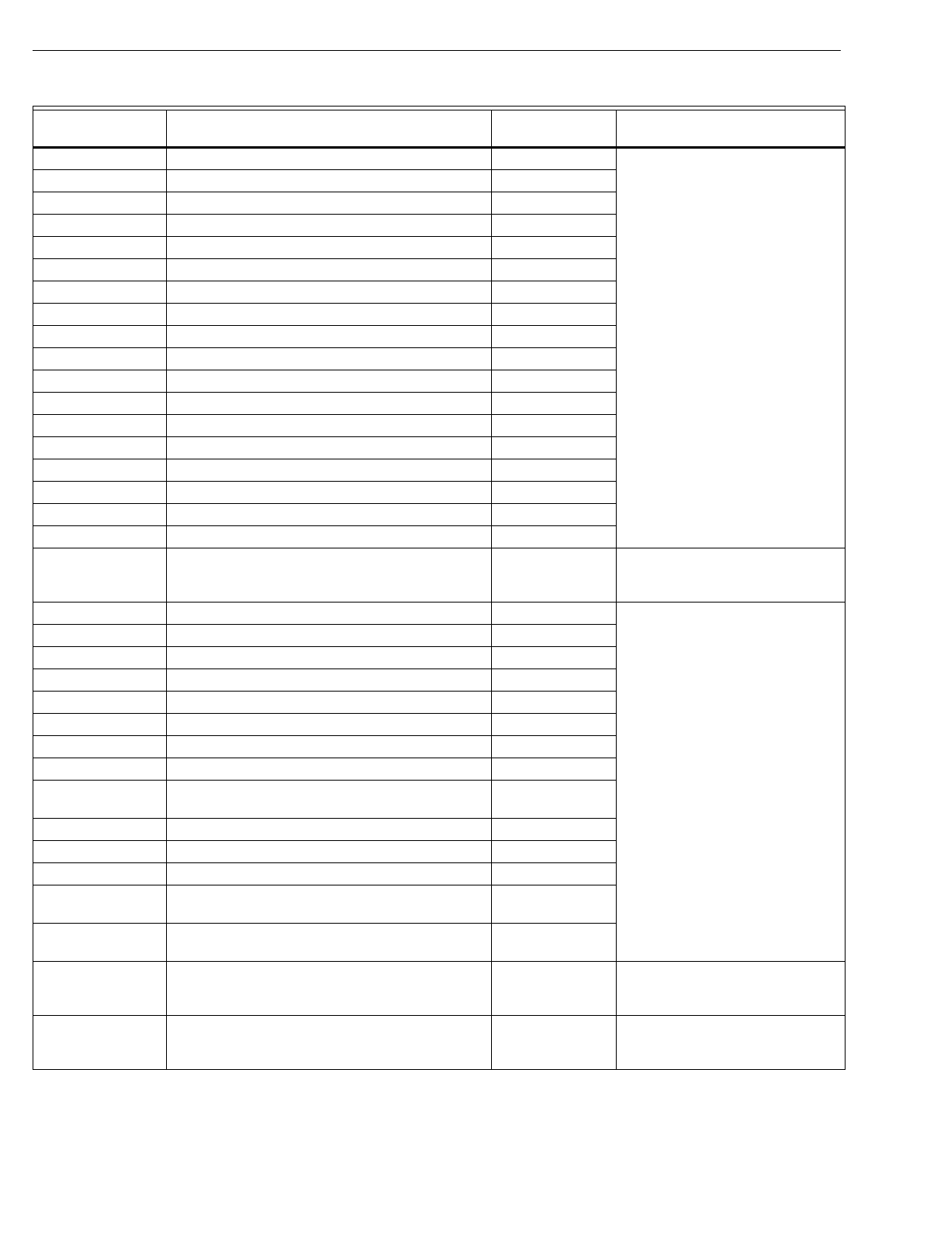
T874 MULTISTAGE THERMOSTATS AND Q674 SUBBASES
60-2485—834
E1036 American Standard lo
g
o T874E1016
E1044 York lo
g
o; lockin
g
cover T874E1016
E1051 ITT lo
g
o T874E1016
E1069 Climatrol lo
g
o T874E1016
E1077 Airtemp
(
Chr
y
sler
)
lo
g
o T874E1016
E1085 Lennox lo
g
o T874E1016
E1093 Trane lo
g
o T874E1016
E1101 Dunham-Bush lo
g
o T874E1016
E1119 Fedders lo
g
o T874E1016
E1127 Climatrol lo
g
o T874E1016
E1135 General Electric lo
g
o; no. AY28X108 T874E1016
E1143 Lennox lo
g
o; Celsius scale T874E1016
E1150 Celsius scale T874E1016
E1168 Airtemp lo
g
o T874E1016
T872F 2-sta
g
e heat
F1001 Standard OEM T874F1015
F1019 TRADELINE T874F1015
F1027 Lennox lo
g
o; fast c
y
cle heat anticipator T874C1018
F1035 Luxaire lo
g
o; fast c
y
cle performance on both heat
sta
g
es. T874C1018 M839 draws 0.72A; set ad
j
ustable
heat anticipator to settin
g
of 0.9A
for proper c
y
cle rate.
F1043 York lo
g
o; lockin
g
cover; used with M839. T874C1018
F1050 Raehco lo
g
o T874F1015
F1068 Fast c
y
cle performance on both heat sta
g
es. T874C1018
F1076 Wesco lo
g
o T874F1015
F1084 Lennox lo
g
o T874F1015
F1092 Auto Gas lo
g
o T874F1015
F1100 Celsius scale T874F1015
F1118 Lennox lo
g
o; Celsius scale T874F1015
F1126 Sta
g
es 1 and 2 heat electricall
y
isolated; used with
Q672D1002 None
F1134 S
q
uare D lo
g
o; HCD-4 T874F1015
F1159 Wesco lo
g
o; heat anticipator set at 0.8A T874F1015
F1167 York lo
g
o T874F1015
F1175 Oneida Heater lo
g
o; no. 30A0287-01; used with
Q672K1012. T874F1015/
Q674K1026
T872G Heat pump models; 2-sta
g
e heat,
1-sta
g
e cool, 1-sta
g
e chan
g
eover.
G1000 Fast c
y
cle performance sta
g
e 2 heat; fixed
anticipator sta
g
e 1 heat and cool; chan
g
eover with
coolin
g
; used with Q672F1018.
Y594G1252 Wirin
g
differences
(
old=new
)
:
W=W2, X1=X.
G1018 Ad
j
ustable anticipator sta
g
e 2 heat; fixed
anticipator sta
g
e 1 heat and cool; chan
g
eover with
coolin
g
; used with Q672E1027.
Y594G1393 Wirin
g
differences
(
old=new
)
:
Y1=O, Y2=Y.
Table 6. T872-T874 Thermostat Cross Reference.
Model Number Description T874 Trade
ReplacementaRemarks
aWhen replacin
g
a T872 Thermostat and Q672 Subbase, alwa
y
s replace both the thermostat and the subbase.
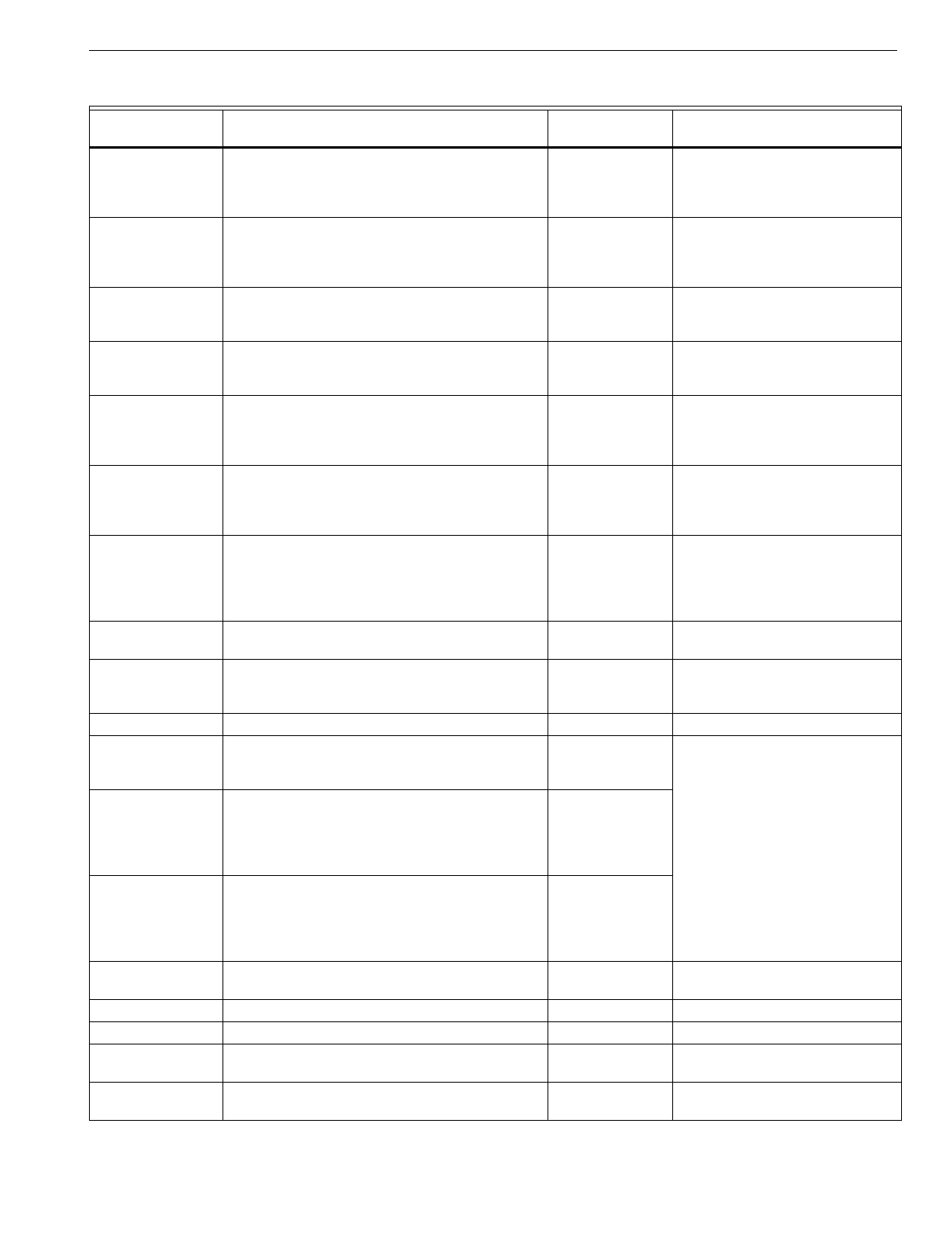
T874 MULTISTAGE THERMOSTATS AND Q674 SUBBASES
35 60-2485—8
G1026 Lennox lo
g
o; fast c
y
cle performance; sta
g
e 2 heat;
fixed anticipator sta
g
e 1 heat and cool;
chan
g
eover with coolin
g
; used with Q672E1019,
F1067.
None See subbase description for
replacement information.
G1034 Westin
g
house lo
g
o; ad
j
ustable anticipator sta
g
e 2
heat; fixed anticipator sta
g
e 1 heat and cool;
chan
g
eover with coolin
g
; used with Q672F1091,
F1141, F1257 or Q672J1013, J1062.
Y594G1252 Wirin
g
differences
(
old=new
)
:
W=W2.
G1042 York lo
g
o; fixed anticipator on all sta
g
es heat and
cool; chan
g
eover with coolin
g
; used with
Q672J1021.
Y594G1567
G1059 TRADELINE; no anticipator sta
g
e 2 heat; fixed
anticipator sta
g
e 1 heat and cool; chan
g
eover with
coolin
g
; used with Q672J1039 outdoor reset.
Y594G1161 Desi
g
ned for use on General
Electric heat pumps.
G1067 Lennox lo
g
o; no. P-8-11222; fast c
y
cle
performance; sta
g
e 2 heat; fixed anticipator sta
g
e
1 heat and cool; chan
g
eover with coolin
g
; used
with Q672E1142, F1083.
See subbase description for
replacement information.
G1075 Carrier lo
g
o; ad
j
ustable anticipator sta
g
e 2 heat;
fixed anticipator sta
g
e 1 heat and cool;
chan
g
eover with coolin
g
; used with Q672J1054,
L1052.
See subbase description for
replacement information.
G1083 Ad
j
ustable anticipator sta
g
e 2 heat; fixed
anticipator sta
g
e 1 heat and cool; chan
g
eover with
coolin
g
; includes shunt to b
y
pass sta
g
e 2
anticipator with auxiliar
y
heat rela
y
s; used with
Q672F1158.
Y594G1252
G1091 Lennox lo
g
o; same as T872G1026 except meets
DoD specs. See subbase description for
replacement information.
G1109 Tappan lo
g
o; no. 080-13708-52; ad
j
ustable
anticipator sta
g
e 1 heat and cool; chan
g
eover with
coolin
g
; used with Q672F1117.
Y594G1252 Wirin
g
differences
(
old=new
)
: C=X.
G1117 Chan
g
eover; used with Q672F1125. Y594G1252 Wirin
g
differences
(
old=new
)
: C=X.
G1125 Lennox lo
g
o; no. 63A0401; Celsius scale; isolated
auxiliar
y
heat power circuit; fast c
y
cle anticipator
sta
g
e 2 heat.
None
G1133 Rheem lo
g
o; no. RXMT-B71; ad
j
ustable
anticipator sta
g
e 2 heat; fixed anticipator sta
g
e 1
heat and cool; chan
g
eover with coolin
g
; includes
shunt to b
y
pass sta
g
e 2 anticipator with auxiliar
y
heat rela
y
s; used with Q672F1158, F1232.
Y594G1252
G1141 Ruud lo
g
o; ad
j
ustable anticipator sta
g
e 2 heat;
fixed anticipator sta
g
e 1 heat and cool;
chan
g
eover with coolin
g
; includes shunt to b
y
pass
sta
g
e 2 anticipator with auxiliar
y
heat rela
y
s; used
with Q672F1158.
Y594G1252
G1158 Carrier lo
g
o; same as T872G1075. Except DoD
st
y
lin
g
. See subbase description for
replacement information.
G1166 BDP used with Q672F1125. Y594G1252 Wirin
g
differences
(
old=new
)
: C=X.
G1174 BDP used with Q672F1125. Y594G1252 Wirin
g
differences
(
old=new
)
: C=X.
G1182 Carrier; no. HH07AT071C; Celsius scale; used
with Q672L1052, J1054. See subbase description for
replacement information.
G1190 Tappan; no. B13708-57; used with Q672L1078 for
8 and 10 ton heat pumps with 2 compressors. None
Table 6. T872-T874 Thermostat Cross Reference.
Model Number Description T874 Trade
ReplacementaRemarks
aWhen replacin
g
a T872 Thermostat and Q672 Subbase, alwa
y
s replace both the thermostat and the subbase.
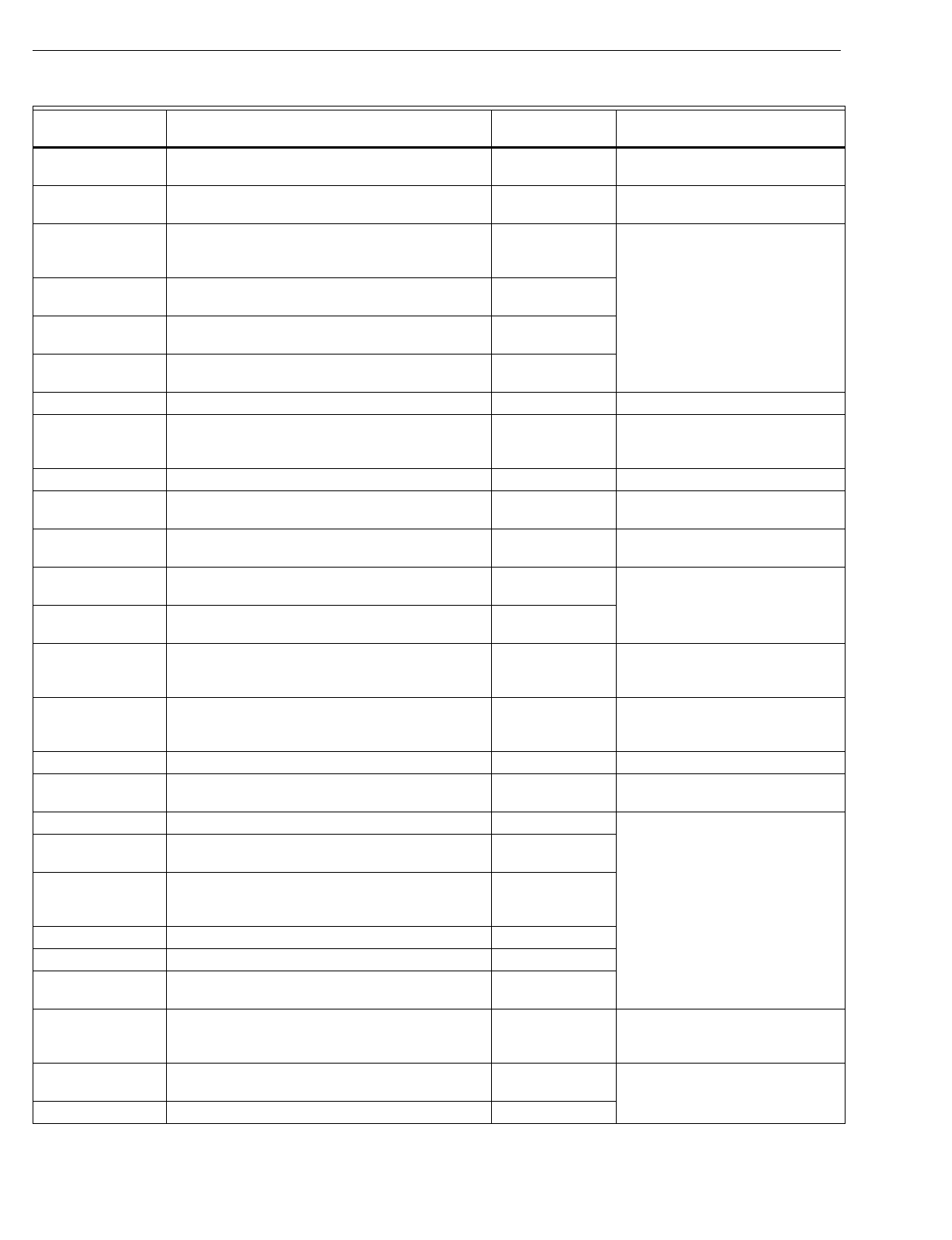
T874 MULTISTAGE THERMOSTATS AND Q674 SUBBASES
60-2485—836
G1208 Marvair lo
g
o; special for Crispaire; used with
Q672F1166, F1323. Y594G1393
G1216 Janitrol lo
g
o; no. 26G05; sta
g
e 2 heat anticipator
set at 1.2A; used with Q672F1117. Y594G1252 Wirin
g
differences
(
old=new
)
: C=X.
G1224 TRADELINE; ad
j
ustable anticipator sta
g
e 2 heat;
fixed anticipator sta
g
e 1 heat and cool;
chan
g
eover in cool; used with Q672F1208.
Y594G1419
G1232 Heat Wave
(
Southwest Mf
g
.
)
lo
g
o; sta
g
e 2 heat
anticipator set at 1.2A; used with Q672F1224.
G1240 Lennox; fast c
y
cle anticipator sta
g
e 2 heat; used
with Q672F1240. None
G1257 Carrier lo
g
o; no. HH07AT073; used with
Q672L1169
(
HH93AZ071
)
.None
G1265 Addison lo
g
o; used with Q672F1265. Y594G1252 Wirin
g
differences
(
old=new
)
: C=X.
G1273 Carrier lo
g
o;
(
DoD model
)
; 68°F
(
20°C
)
maximum
heatin
g
; 78°F
(
26°C
)
minimum coolin
g
; used with
Q672L1052, J1054
See subbase description for
replacement information.
G1281 Wesco lo
g
o; used with Q672F1265. Y594G1252 Wirin
g
differences
(
old=new
)
: C=X.
G1299 York lo
g
o; meets DoD specs; used with
Q672L1177. Y594G1567
G1307 Carrier; no. 38EQ1900; Celsius; used with
Q672J1054, L1052. See subbase description for
replacement information.
G1315 Luxaire special; sta
g
e 2 heat anticipator set to
1.2A; used with Q672F1281. Y594G1252
G1323 Lennox special; used with Q672L1201 and
C815A1013. None
G1331 York; used with Q672J1021. Y594G1567 Wirin
g
differences
(
old=new
)
:
X=X1, L=X2, W=E; Y1-W1 and Y2-
W2
j
umpers re
q
uired.
G1356 Westin
g
house; used with Q672L1219. T874D1165/
Q674F1022 Wirin
g
differences
(
old=new
)
:
X=X1, L=X2, W=E; Y1-W1 and Y2-
W2
j
umpers re
q
uired.
G1364 York; used with Q672D1077. None
G1372 Tappan/Janitrol lo
g
o; no. B-13708-521;
used with Q672F1117. Y594G1252 Wirin
g
differences
(
old=new
)
: C=X.
G1398 York lo
g
o; no. 025-21454C; used with Q672J1021. Y594G1567
T872H Heat pump model; 1 sta
g
e heat,
1 sta
g
e cool, 1 sta
g
e chan
g
eover.
H1009 Command-Aire lo
g
o; fixed anticipator sta
g
e 1 heat
and cool; chan
g
eover with coolin
g
; used with
Q672C1086.
Y594H1012
H1017 Friedrich lo
g
o. Y594H1012
H1025 Friedrich lo
g
o; Celsius. Y594H1012
T872M 1 sta
g
e heat, 1 sta
g
e cool with sta
g
e 2 heat factor
y
set at 60°F
(
16°C
)
.
M1003 Standard OEM; used with Q672D and external
switchin
g
means. T874C1125 T874C1125 has 12°F
(
6.7°C
)
differential between sta
g
e 1 and
sta
g
e 2 heat.
T872N Heat pump model; 2-sta
g
e heat, 1-sta
g
e cool plus
chan
g
eover, chan
g
eover in heat mode.
N1002 None
Table 6. T872-T874 Thermostat Cross Reference.
Model Number Description T874 Trade
ReplacementaRemarks
aWhen replacin
g
a T872 Thermostat and Q672 Subbase, alwa
y
s replace both the thermostat and the subbase.
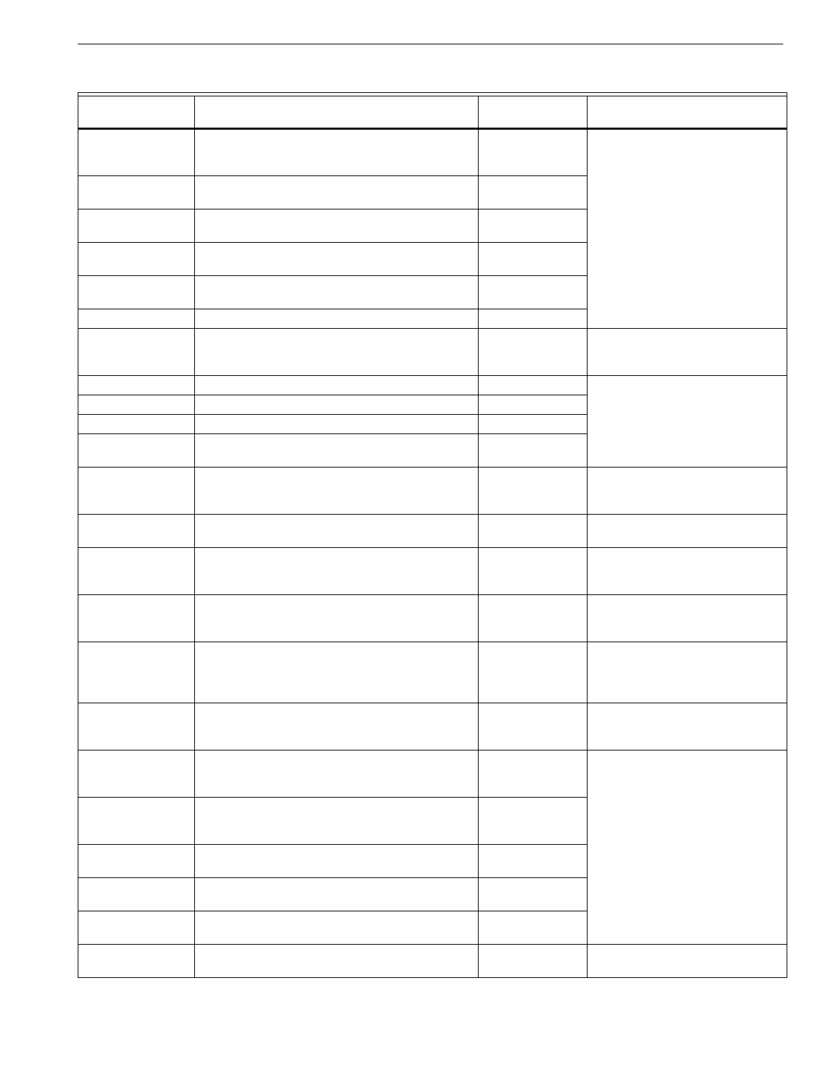
T874 MULTISTAGE THERMOSTATS AND Q674 SUBBASES
37 60-2485—8
N1010 Williamson lo
g
o; ad
j
ustable anticipator sta
g
e 1
and 2 heat; fixed anticipator sta
g
e 1 cool; used
with Q672F1133 or F1315.
T874N1016/
Q674F1220
N1028 TRADELINE heat mode chan
g
eover; used with
Q672F1216. T874N1016
N1036 Bard; used with Q672F1299. T874N1016/
Q674F1220
N1044 Thermotron lo
g
o; 1st sta
g
e chan
g
eover heat
mode; used with Q672F1299. T874N1016/
Q674F1220
T872Q 1-sta
g
e heat; used with another T872 for heatin
g
setback.
Q1009 Standard OEM T874C1125
Q1017 York lo
g
o T874C1125 Replacement onl
y
g
ood for
1-sta
g
e heat and 1-sta
g
e cool
applications.
Q1025 ITT lo
g
oNone
Q1033 Lennox lo
g
o; no. P-8-8899. None
Q1041 Lennox lo
g
o; no. 63A6401. None
T872R Heat pump model; 2-sta
g
e heat, 1-sta
g
e cool,
manual chan
g
eover.
R1008 Fixed anticipator sta
g
e 1 heat and cool; no
anticipator sta
g
e 2 heat; chan
g
eover with coolin
g
;
used with Q672B1046.
Y594R1425 Wirin
g
differences
(
old=new
)
:
W=W2; W1-Y1
j
umper re
q
uired.
R1016 Addison same as T872R1008; used with
Q672B1103. Y594R1425 Wirin
g
differences
(
old=new
)
:
W=W2; W1-Y1
j
umper re
q
uired.
R1024 Lennox lo
g
o; fast c
y
cle sta
g
e 2 heat; fixed
anticipator sta
g
e 1 heat and cool; chan
g
eover with
coolin
g
; used with Q672B1160 and Q672L1003.
See subbase description for
replacement information.
R1032 York lo
g
o; fixed anticipator sta
g
e 1 and 2 heat and
sta
g
e 1 cool; chan
g
eover with coolin
g
; used with
Q672L1011.
Y594R1664
R1040 Lennox lo
g
o; fast c
y
cle sta
g
e 2 heat; fixed
anticipator sta
g
e 1 heat and cool; isolated sta
g
e 2
heat switch; chan
g
eover with coolin
g
; used with
Q672B1202 no. P-8-11221, Q672L1029
See subbase description for
replacement information.
R1057 TRADELINE; fixed anticipator sta
g
e 1 heat and
cool; no anticipator sta
g
e 2 heat; chan
g
eover on
coolin
g
; used with Q672L1037; outdoor reset.
Y594R1763 Desi
g
ned for use on General
Electric heat pumps. Wirin
g
differences
(
old=new
)
: A=T.
R1065 Ad
j
ustable anticipator sta
g
e 2 heat; fixed
anticipator sta
g
e 1 heat and cool; chan
g
eover on
coolin
g
; used with Q672L1045.
Y594R1243
R1073 Lennox lo
g
o; no. 63A0301; Celsius scale;
separate auxiliar
y
heat power circuit; fast c
y
cle
sta
g
e 2 heat antic.
None
R1081 Ruud lo
g
o; same circuit as T872R1065; used with
Q672L1045, L1136. Y594R1243
R1099 Dunham Bush special; used with Q672L1060,
L1383. Y594R1243
R1107 Rheem; no. RXMT-B70; used with Q672L1045,
L1136. Y594R1243
R1115 Friedrich lo
g
o; fixed anticipator; used with
Q672B1244, L1086. See subbase description for
replacement information.
Table 6. T872-T874 Thermostat Cross Reference.
Model Number Description T874 Trade
ReplacementaRemarks
aWhen replacin
g
a T872 Thermostat and Q672 Subbase, alwa
y
s replace both the thermostat and the subbase.
T874 MULTISTAGE THERMOSTATS AND Q674 SUBBASES
60-2485—838
R1123 York lo
g
o; no. 025-21453C; Celsius scale. Y594R1664
R1131 Lennox lo
g
o; separate auxiliar
y
heat power circuit;
fast c
y
cle sta
g
e 2 heat anticipator; outdoor reset;
used with Q672L1144, C815A1013.
None
R1149 Westin
g
house lo
g
o; ad
j
ustable sta
g
e 2 heat
anticipator; coolin
g
chan
g
eover; fixed anticipator
sta
g
e 1 heat and cool; used with Q672L1110,
L1128, L1151.
Y594R1243 Wirin
g
differences
(
old=new
)
:
W=W2.
R1156 Marvair lo
g
o; used with Q672L1094, L1250. Y594R1243 Replacement has auto fan in
Emer
g
enc
y
Heat mode.
R1164 Bard; used with Q672L1185. Y594R1243
R1172 Heil Quaker; used with Q672L1193. Y594R1243 Wirin
g
differences
(
old=new
)
: B=X,
W=W2.
R1180 York; Celsius; used with Q672L1011. Y594R1664
R1198 TRADELINE; used with Q672L1227 Y594R1243
R1206 For use with W89; used with Q672L1235. None
R1214 Intertherm lo
g
o; used with Q672L1276. Y594R1300 Wirin
g
differences
(
old=new
)
:
W1=B, Z=L, K=E.
R1222 York lo
g
o; used with C815A1039; ad
j
ustable
anticipator sta
g
e-2 heat; used with Q672L1284 Y594R1672
R1230 Amana lo
g
o; no. C62397-1; used with
Q672L1300, W89. None
R1255 Sin
g
er lo
g
o; used with Q672L1326 and W89. None
R1271 Westin
g
house lo
g
o; used with Q672L1375 and
W89. Y594R1664
R1297 York; Celsius scale; used with Q672L1011. None
R1305 Used with Q672L1235 and W89. None
R1321 Duotherm lo
g
o; used with Q672L1409, and W89. None
R1339 Williamson; used with Q672L1391. Y594R1243
T872S Heat pump model; 2-sta
g
e heat plus chan
g
eover,
1-sta
g
e cool.
S1005 Westin
g
house lo
g
o; ad
j
ustable anticipator sta
g
e 1
and 2 heat; fixed anticipator sta
g
e 1 heat;
chan
g
eover with heatin
g
: used with Q672C1045
T874C1018/
Q674C1058 Wirin
g
differences
(
old=new
)
:
V=RC-RH, F=G, C=Y1, Z=B,
H2=W2; W1-Y1
j
umper re
q
uired.
T872T 1-heat sta
g
e, 1-vent and 2-cool sta
g
es.
T1004 Trane lo
g
o; used with Q672B1129. None
T872W 3-heat sta
g
es, 2-cool sta
g
es, manual chan
g
eover
W1019 Lennox lo
g
o; no. 52C7501; used with Q672L1342
and C815A1013. None
W1027 Westin
g
house lo
g
o; used with Q672L1268 and
C815A1021. None
W1035 TRADELINE; used with C815A1043 and
Q672B1251. Y594W1014
Table 6. T872-T874 Thermostat Cross Reference.
Model Number Description T874 Trade
ReplacementaRemarks
aWhen replacin
g
a T872 Thermostat and Q672 Subbase, alwa
y
s replace both the thermostat and the subbase.
T874 MULTISTAGE THERMOSTATS AND Q674 SUBBASES
39 60-2485—8
Table 7. Q672-Q674 Subbase Cross Reference.
Model Number Description Q674 Trade
ReplacementaRemarks
Q672A S
y
stem: HEAT-AUTO-COOL, Fan: AUTO-ON
A1005 Standard OEM Q674A1019
A1013 TRADELINE Q674A1019
A1021 RC-RH
j
umper Q674A1019 RC-RH
j
umper re
q
uired.
A1039 RC-RH
j
umper; Chek Lite Q674A1019 RC-RH
j
umper re
q
uired.
Q672B S
y
stem: HEAT-OFF-COOL, Fan: AUTO-ON
B1004 Standard OEM Q674B1034
B1012 Isolated G terminal. Q674B1018
B1020 S
y
stem: HEAT-OFF-RESET-COOL Q674B1034 Used s
y
stem off as reset position.
B1038 TRADELINE Q674B1034
B1046 Heat pump circuit; used with T872R1008. Y594R1425 Wirin
g
differences
(
old=new
)
:
W1=Y1, W=W2.
B1053 RC-RH
j
umper Q674B1034 RC-RH
j
umper re
q
uired.
B1061 Chek Lite Q674B1034
B1079 Auto fan operation in heat and cool. Q674B1075
B1087 Carrier no. HH93AZ078; RC-RH
j
umper. Q674B1075
B1095 Carrier no. HH93AZ084; RC-RH
j
umper. Q674B1034
B1103 Addison; heat pump circuit; used with
T872R1016. Y594R1425 Wirin
g
differences
(
old=new
)
:
W=W2; W1-Y1
j
umper re
q
uired.
B1111 Carrier no. HH93AZ080; isolated G terminal. Q674B1018
B1129 Trane special circuit; used with T872T1004. None
B1137 RC-RH
j
umper; isolated G terminal. Q674B1018 RC-RH
j
umper re
q
uired.
B1145 Fedders special Q674B1034 RC-RH
j
umper re
q
uired.
B1152 Fedders special; auto fan operation in heat
and cool. Q674B1075
B1160 Lennox; heat pump circuit; used with
T872R1024; includes compressor lockout in
EM. HT.
Y594R1243 Wirin
g
differences
(
old=new
)
:
V-VR=R, M=Y, Y=W2, F=G, R=O.
B1178 General Electric no. AY28X107; auto fan
operation in heat and cool. Q674B1075
B1186 Trane; isolated G terminal; Filter LED. Q674B1018
B1194 General Electric no. AY28X124; auto fan
operation in heat and cool. Q674B1075 Set T874 sta
g
e-1 anticipator for
combined load of heat rela
y
and fan
rela
y
.
B1202 Lennox no. P-8-11223; heat pump circuit; used
with T872R1040. Y594R1243 Wirin
g
differences
(
old=new
)
:
V-VR=R, M=Y, Y=W2, F=G, R=O.
B1210 None
B1228 General Electric no. BAY28X137; isolated
G terminal. Q674B1018
B1236 Carrier no. HH-93AZ079; RC-RH
j
umper;
LOCKOUT LED indicates compressor lockout
switch activated.
Q674B1034 RC-RH
j
umper; LED cannot be
provided in TRADELINE model.
B1244 Friedrich; heat mode chan
g
eover; used with
T872R1115. T874C1018/
Q674B1034 Wirin
g
differences
(
old=new
)
: C=no
connection; RC-RH and W1-Y1
j
umpers re
q
uired.
B1251 Used with T872W1035 and C815A1043. Y594W1014
aWhen replacin
g
a T872 Thermostat and Q672 Subbase, alwa
y
s replace both the thermostat and subbase.
T874 MULTISTAGE THERMOSTATS AND Q674 SUBBASES
60-2485—840
B1269 Whalen; Hi-Lo fan switch; constant fan in heat
and cool s
y
stem switch positions; used with
T872C1574.
None
B1277 S
q
uare D no. HCB-5. Q674B1034
B1285 Wards; RC-RH and F-W3
j
umpers; used with
T872C1673. Gas Furnace:
T874C1018/
Q674B1034
Electric Furnace:
T874C1018/
Q674B1075
Ad
j
ust anticipator
faster
for correct
performance.
B1293 Lennox no. 41C96; used with T872C1673. Same as
Q672B1285
Q672C S
y
stem: OFF-AUTO, Fan: AUTO-ON
C1003 Standard OEM Q674C1058
C1011 Westin
g
house; RC-RH
j
umper. Q674C1058 RC-RH
j
umper re
q
uired.
C1029 W1-Y2
j
umper; for heat pump; used with
T872D1136. Q674E1049 Replacement has heat/cool s
y
stem
switchin
g
.
C1037 Chr
y
sler Airtemp; S
y
stem: COOL-OFF-AUTO. Q674C1058
C1045 Westin
g
house; heat pump; used with
T872S1005. T874C1018/
Q674C1058 Wirin
g
differences
(
old=new
)
:
V=RC-RH, F=G, C=Y1, Z=B,
H2=W2; W1-Y1
j
umper re
q
uired.
C1052 Isolated sta
g
e 2 heat circuit for dc electric heat
rela
y
.Recontrol Use T874G1246/Q674F1212 which
adds HEAT-COOL-EM.HT. s
y
stem
switch.
C1060 Fedders special. Q674C1058
C1078 General Electric no. AY28X109. Q674C1058
C1086 Command-Aire; heat pump; used with
T872H1009. Y594H1012
C1102 TRADELINE Q674C1058
Q672D S
y
stem: None. Fan: None.
D1002 Standard OEM; used with T872F1126. Q674D1040
D1010 Lennox special. None
D1028 Carrier; RC-RH
j
umper. None
D1036 Carrier no. HH93AZ070; RC-RH
j
umper. Q674D1040 RC-RH
j
umper re
q
uired.
D1044 General Electric no. AY-28X100. None
D1069 S
q
uare D no. HCB-4. None
D1077 York; used with T872G1364. None
D1085 TRADELINE Q674D1040
Q672E S
y
stem: OFF-HEAT-AUTO-COOL
Fan: AUTO-ON
E1001 Standard OEM Q674E1049
E1019 Lennox no. P-8-8892; heat pump; cool mode
chan
g
eover; used with T872G1026. T874D1165/
Q674B1075
E1027 Heat pump circuit; W1-Y2
j
umper; cool mode
chan
g
eover; used with T872G1018. Y594G1393 Wirin
g
differences
(
old=new
)
: Y1=O,
Y2=Y.
E1035 Heat pump circuit; W1-Y2
j
umper; cool mode
chan
g
eover. Y594G1393 Wirin
g
differences
(
old=new
)
: Y1=O,
Y2=Y.
E1043 Heat pump circuit; heat mode chan
g
eover. Q674E1049 Wirin
g
differences
(
old=new
)
:
W1=B, W2=W1; W1-Y1
j
umper.
Table 7. Q672-Q674 Subbase Cross Reference.
Model Number Description Q674 Trade
ReplacementaRemarks
aWhen replacin
g
a T872 Thermostat and Q672 Subbase, alwa
y
s replace both the thermostat and subbase.
T874 MULTISTAGE THERMOSTATS AND Q674 SUBBASES
41 60-2485—8
E1050 TRADELINE Q674E1049
E1068 RC-RH
j
umper; used with T872C1699. Q674E1049 RC-RH
j
umper re
q
uired.
E1076 RC-RH internal
j
umper; EM. HT. LED. Q674E1049 RC-RH
j
umper re
q
uired.
E1084 Carrier no. HH93AZ076; RC-RH
j
umper. Q674E1049 RC-RH
j
umper re
q
uired.
E1092 Carrier no. HH93AZ082; RC-RH
j
umper; B
terminal; isolated G terminal. Q674E1049
E1100 General Electric no. AY28X099. Q674E1049
E1118 Airtemp; heat pump; used with T872D1169. T874D1165/
Q674E1049 Wirin
g
differences
(
old=new
)
:
A=W1; set H1 anticipator to 1.2A.
E1126 Common R terminal. Q674E1049 RC-RH
j
umper re
q
uired.
E1134 ITT Nesbitt; RC-RH
j
umper; O and B terminals;
isolated G terminal. Q674E1049
E1142 Lennox no. P-8-11224; heat pump;
V-VR
j
umper; cool mode chan
g
eover; used with
T872G1067.
Y594G1252 Wirin
g
differences
(
old=new
)
:
V-VR=R, Y=W2, R=O, M=Y, F=G.
E1159 Carrier no. HH93AZ077; RC-RH
j
umper;
LOCKOUT LED indicates activation of
compressor lockout switch.
Q674E1049 RC-RH
j
umper re
q
uired; no LED in
TRADELINE model.
E1167 S
q
uare D no. HCB-2; Chek Lite. Q674E1049
E1183 S
q
uare D no. HCB-3. Q674E1049
E1191 Lennox; HIGH and LOW LEDs; used with
T872D1045. Q674E1049 No LEDs on replacement.
Q672F S
y
stem: EM. HT.-HEAT-AUTO-COOL-OFF
Fan: AUTO-ON.
F1000 With EM. HT. LED; used with T872C1699. Q674F1022 Remove W3-X2
j
umper to E-X2.
F1018 Heat pump; heat mode chan
g
eover; Chek Lite;
used with T872G1000. Y594G1252 Wirin
g
differences
(
old=new
)
:
W=W2, X1=X.
F1026 Chek Lite; W2-X2
j
umper. Q674F1022
F1034 Airtemp; EM. HT. LED; RC-RH and X2-E
j
umpers. Q674F1022 If RC-RH
j
umper removed on
Q672F1034, Q674F1022 does not
replace.
F1042 W2-X2
j
umper; Chek Lite. Q674F1022
F1059 Carrier no. HH93AZ074; EM. HT. LED. Q674F1022 Remove W2-X2
j
umper to E-X2; X
terminal same as C.
F1067 Lennox; heat pump; cool mode chan
g
eover;
EM. HT. LED; used with T872G1026. None
F1075 Heat pump circuit; EM. HT. LED; 2 terminal; RC-
RH
j
umper. None
F1083 Lennox no. P-8-11225; heat pump;
V-VR
j
umper; cool mode chan
g
eover; EM. HT.
LED; used with T872G1067.
None
F1091 Westin
g
house; heat pump; EM. HT. LED; cool
mode chan
g
eover; compressor lockout in
EM. HT.; used with T872G1034.
Y594G1252 Wirin
g
differences
(
old=new
)
:
W=W2.
F1109 Airtemp no. 3778567ACC; R-X2
j
umper;
EM. HT. LED. Q674F1022 R-X2
j
umper re
q
uired.
F1117 Tappan no. 080-13708-53; heat pump; EM. HT.
LED; cool mode chan
g
eover; compressor
lockout and auto fan in EM. HT.; used with
T872G1109, G1216, G1372.
Y594G1252 Wirin
g
differences
(
old=new
)
: C=X.
Table 7. Q672-Q674 Subbase Cross Reference.
Model Number Description Q674 Trade
ReplacementaRemarks
aWhen replacin
g
a T872 Thermostat and Q672 Subbase, alwa
y
s replace both the thermostat and subbase.
T874 MULTISTAGE THERMOSTATS AND Q674 SUBBASES
60-2485—842
F1125 BDP no. 3442DP90; used with T872G1117,
G1166, G1174. Y594G1252 Wirin
g
differences
(
old=new
)
: C=X.
F1133 Williamson; heat pump; EM. HT. LED; heat
mode chan
g
eover; compressor lockout in
EM. HT.; used with T872N1010.
T874N1016/
Q674F1220
F1141 Westin
g
house; EM. HT. LED; auto fan in
EM. HT.; used with T872G1034. Y594G1252 Wirin
g
differences
(
old=new
)
:
W=W2.
F1158 Rheem Ruud; heat pump; EM. HT. LED; cool
mode chan
g
eover; compressor lockout in
EM. HT.; used with T872G1083, G1133, G1141;
auto fan in EM. HT.
Y594G1252
F1166 Crispaire; EM. HT. LED; used with T872G1208. Y594G1252
F1174 Carrier no. HH93AZ081; EM. HT. LED. Q674F1022
F1182 S
q
uare D no. HCB-1; Chek Lite; R-X2
j
umper;
S
y
stem: Aux. Heat replaces EM. HT. Q674F1022 R-X2
j
umper; add monitor switch
between X1 and low side of power.
F1190 EM. HT. LED; X2-E and RC-RH
j
umpers. None
F1208 TRADELINE; cool mode chan
g
eover; EM. HT.
LED; used with T872G1224. Y594G1419
F1216 TRADELINE; heat mode chan
g
eover; EM. HT.
LED; used with T872N1028. T874N1016/
Q674F1220
F1224 Heatwave
(
Southwest Mf
g
.
)
; compressor
lockout in EM. HT.; EM. HT. LED; used with
T872G1232.
Y594G1252
F1232 Rheem; cool mode chan
g
eover; EM. HT. and
AUX. HEAT LEDs; compressor lockout in
EM. HT.; used with T872G1133.
Y594G1252
F1240 Lennox; cool mode chan
g
eover; EM. HT. and
SERVICE LEDs; used with T872G1240. None
F1257 Westin
g
house; cool mode chan
g
eover;
EM. HT. and AUX. HEAT LEDs; auto fan in
EM. HT; used with T872G1034.
Y594G1252 Wirin
g
differences
(
old=new
)
:
W=W2.
F1265 Wesco Addison; Chek and EM. HT. LEDs; used
with T872G1281, G1265. Y594G1252 Wirin
g
differences
(
old=new
)
: C=X.
F1273 Southwest special; no. 0361-136; W2-X2
j
umper. None
F1281 Luxaire special; used with T872G1315. Y594G1252
F1299 Bard special; used with T872N1036, N1044. T874N1016/
Q674F1220
F1315 Williamson special; used with T872N1010. T874N1016/
Q674F1220
F1323 Crispaire special; used with T872G1208. Y594G1252
Q672G S
y
stem: OFF-AUTO. Fan: None.
G1009 Standard OEM Q674G1070
G1017 Sin
g
er; O-B
j
umper; used with T872D1375. Q674G1070
G1025 Includes O and B terminals. Q674G1070
G1033 General Electric no. AY28X102. Q674G1070
G1041 Sin
g
er no. 02005649; French wordin
g
; O-B
j
umper. Q674G1070 Less French wordin
g
.
G1066 SLI-Mammoth; heat pump; heat mode
chan
g
eover. Q674G1070 Connect fan
(
G
)
wire to Y1 terminal;
B-O and RC-RH
j
umpers.
Table 7. Q672-Q674 Subbase Cross Reference.
Model Number Description Q674 Trade
ReplacementaRemarks
aWhen replacin
g
a T872 Thermostat and Q672 Subbase, alwa
y
s replace both the thermostat and subbase.
T874 MULTISTAGE THERMOSTATS AND Q674 SUBBASES
43 60-2485—8
G1074 Sin
g
er no. 02005754; X1 and X2 terminals for
field-added indicator li
g
hts; used with
T872D1375.
None
G1082 Sin
g
er no. 02005792; X1 and X2 terminals for
field-added indicator li
g
hts; used with
T872D1375.
None
G1090 TRADELINE; B and O terminals. Q674G1070
Q672H S
y
stem: OFF-ON
Fan: NIGHT INT.-DAY CONT.
H1008 Used with T872. None
Q672J S
y
stem: EM. HT.-AUTO-OFF
Fan: AUTO-ON.
J1005 With EM. HT. LED; used with T872C or D. None
J1013 Westin
g
house; heat pump; EM. HT. LED; cool
mode chan
g
eover; compressor lockout in
EM. HT.; used with T872G1034.
Y594G1252
J1021 York; heat pump; EM. HT. LED; cool mode
chan
g
eover; compressor lockout and auto fan in
EM. HT.; E-W
j
umper; used with T872G1042,
G1331, G1398.
Y594G1567
J1039 Heat pump; EM. HT. and AUX. HEAT LEDs;
cool mode chan
g
eover; compressor lockout and
auto fan in EM. HT.; used with T872G1059.
Y594G1161 Desi
g
ned for use on General
Electric heat pumps.
J1047 Sin
g
er no. 02005699; heat pump; EM. HT. LED;
heat mode chan
g
eover. Q674F1022
J1054 Carrier no. HH93AZ073A; heat pump; EM. HT.
LED; cool mode chan
g
eover; compressor
lockout in EM. HT.; used with T872G1075,
G1182, G1307.
Y594G1252 Wirin
g
differences
(
old=new
)
: C=X.
J1062 Westin
g
house; EM. HT. and AUX. HEAT LEDs;
used with T872G1034. Y594G1252 Wirin
g
differences
(
old=new
)
:
W=W2.
Q672K S
y
stem: OFF-HEAT-AUTO-COOL. Fan: None.
K1004 Carrier no. HH93AZ072. Q674E1049 Fan switch does not function.
K1012 Oneida Heater no. 30A0288-01; S
y
stem: OFF-
WOOD-WOOD/OIL-OIL; used with T872F1175. T874F1155/
Q674K1026
Q672L S
y
stem: EM. HT.-HEAT-OFF-COOL.
Fan: ON-AUTO.
L1003 Lennox; heat pump; EM. HT. LED; cool mode
chan
g
eover; used with T872R1024. Y594R1425
L1011 York; heat pump; EM. HT. LED; cool mode
chan
g
eover; compressor lockout and auto fan in
EM. HT.; used with T872R1032, R1180, R1297.
Y594R1664
L1029 Lennox no. P-8-11226; heat pump; EM. HT.
LED; V-VR
j
umper; cool mode chan
g
eover;
compressor lockout in EM. HT.; used with
T872R1040.
Y594R1425 Wirin
g
differences
(
old=new
)
:
V-VR=R, M=Y, Y=W2, F=G, R=O.
L1037 Heat pump; EM. HT. and AUX. HT. LEDs; cool
mode chan
g
eover; compressor lockout and auto
fan in EM. HT.; used with T872R1057.
Y594R1763 Wirin
g
differences
(
old=new
)
: A=T;
desi
g
ned for used on General
Electric heat pumps.
L1045 Rheem; heat pump; EM. HT. LED; cool mode
chan
g
eover; compressor lockout in EM. HT.;
auto fan in EM. HT; used with T872R1065,
R1081, R1107.
Y594R1243
Table 7. Q672-Q674 Subbase Cross Reference.
Model Number Description Q674 Trade
ReplacementaRemarks
aWhen replacin
g
a T872 Thermostat and Q672 Subbase, alwa
y
s replace both the thermostat and subbase.
T874 MULTISTAGE THERMOSTATS AND Q674 SUBBASES
60-2485—844
L1052 Carrier no. HH93AZ075; heat pump; EM. HT.
LED; cool mode chan
g
eover; compressor
lockout in EM. HT.; used with T872G1075,
G1182, G1273, G1307.
Y594R1615 Wirin
g
differences
(
old=new
)
: C=X.
L1060 Dunham Bush; EM. HT. LED; used with
T872R1099. Y594R1243
L1078 Tappan no. B13708-58; heat pump; EM. HT.
LED; cool mode chan
g
eover; compressor
lockout in EM. HT.; EM. HT. rela
y
provides fan
operation in EM. HT.; used with T872G1190.
None
L1086 Friedrich; heat mode chan
g
eover; EM. HT. LED;
used T872R1115 with L terminal. Y594R1243 Wirin
g
differences
(
old=new
)
: X2=E,
C=X.
L1094 Crispaire; W2-H
j
umper; EM. HT. LED; used
with T872R1065, R1156. Y594R1243 Replacement has auto fan in
Emer
g
enc
y
Heat mode.
L1102 Fedders; heat mode chan
g
eover; EM. HT. LED;
used with T872C1509, C1517, C1541. Y594R1425 Wirin
g
differences
(
old=new
)
: K=E,
C=X; remove Y-W1
j
umper.
L1110 Westin
g
house; EM. HT. LED; used with
T872R1149. Y594R1243 Wirin
g
differences
(
old=new
)
:
W=W2.
L1128 Westin
g
house; EM. HT. LED; used with
T872R1149. Y594R1243 Wirin
g
differences
(
old=new
)
:
W=W2.
L1136 Rheem no. 41-20796-07; cool mode
chan
g
eover; EM. HT. and AUX. HT. LEDs; used
with T872R1081, T872R1107.
Y594R1243
L1144 Lennox; V-VR
j
umper; EM. HT. and SERVICE
LEDs; isolated sta
g
e 2 heat; used with
T872R1131, C815A1013.
None
L1151 Westin
g
house; AUX. HT. and EM. HT. LEDs;
used with T872R1149. Y594R1243 Wirin
g
differences
(
old=new
)
:
W=W2.
L1169 Carrier no. HH93AZ071; EM. HT. LED; used
with T872G1257
(
HH07AT073
)
.None
L1177 York; DoD; EM. HT. LED; used with T872G1299. Y594G1567
L1185 Bard; used with T872R1164. Y594R1243
L1193 Heil Quaker no. NAXA001TS01; used with
T872R1172. Y594R1243 Wirin
g
differences
(
old=new
)
: B=X,
W=W2.
L1201 Lennox special; no. 1485701; used with
T872G1323. None
L1219 Westin
g
house special; used with T872G1356. T874D1165/
Q674F1022 Wirin
g
differences
(
old=new
)
: X=X1,
L=X2, W=E; Y1-W1 and
Y2-W2
j
umpers re
q
uired.
L1227 Heat pump; used with T872R1198. Y594R1243
L1235 Intertherm; used with T872R1206, R1305. None
L1250 Crispaire special; used with T872R1156 and
C815A1021. Y594R1243
L1268 Westin
g
house special; used with T872W1027
and C815A1021. None
L1276 Intertherm special; used with T872R1214. Y594R1300 Wirin
g
differences
(
old=new
)
:
W1=B, Z=L, K=E.
L1284 York special; used with T872R1222. Y594R1672
L1300 Amana special; no. C62345-1; used with
T872R1230. None
L1326 Sin
g
er; used with T872R1255. None
Table 7. Q672-Q674 Subbase Cross Reference.
Model Number Description Q674 Trade
ReplacementaRemarks
aWhen replacin
g
a T872 Thermostat and Q672 Subbase, alwa
y
s replace both the thermostat and subbase.
T874 MULTISTAGE THERMOSTATS AND Q674 SUBBASES
45 60-2485—8
L1342 Lennox no. 52C7601; used with T872W1019
and C815A1013. None
L1375 Westin
g
house; used with T872R1271, W89. None
L1383 Dunham Bush; used with T872R1099. Y594R1243
L1391 Williamson; used with T872R1339. Y594R1243
L1409 Duotherm special; used with T872R1321, W89. None
Q672N S
y
stem: OFF-HEAT-COOL-EVAP.
N1001 Goettl; heat pump; heat mode chan
g
eover;
evaporative cooler circuit; Fan: AUTO-ON;
S
y
stem: AUTO; used with T872C1459.
None
N1019 Goettl; heat pump; heat mode chan
g
eover;
evaporative cooler circuit; W1-Y1
j
umper; used
with T872C1459.
None
N1027 Sie
g
ler special; used with T872C1707. None
Q672P S
y
stem: EM. HT.-HEAT-COOL.
P1009 Carrier special; no. HH93AZ069; used with
T872G1075
(
HH07AT071
)
.Y594R1243 Replacement has OFF s
y
stem
switch position
Table 7. Q672-Q674 Subbase Cross Reference.
Model Number Description Q674 Trade
ReplacementaRemarks
aWhen replacin
g
a T872 Thermostat and Q672 Subbase, alwa
y
s replace both the thermostat and subbase.
T874 MULTISTAGE THERMOSTATS AND Q674 SUBBASES
60-2485—846
Table 8. T874 Cross Reference.
Model
Number Fig.
No. Description Trade Model
Replacement Remarks
T874A 1-sta
g
e heat, 1-sta
g
e cool.
A1002 44, 65 Hone
y
well lo
g
o; Standard OEM; used with Q674B1331. T874A1036
A1010 44 Hone
y
well lo
g
o; includes Allen wrench and screws to
lock cover; non-ad
j
ustable ran
g
e stops set at 72°F
(
max.
heat
)
and 78°F
(
min. cool
)
(
22-26°C
)
; field ad
j
ustable
lockin
g
levers.
T874A1010
A1028 44 Hone
y
well lo
g
o; heat anticipator factor
y
set at 0.4A. T874A1036
A1036 44 Hone
y
well lo
g
o; TRADELINE® model; includes Allen
wrench and screws to lock cover; field ad
j
ustable
lockin
g
levers.
T874A1036
A1044 44 Obsolete. AAF/Sn
y
der General lo
g
o; part no. 4ELN-
3006C; °F/°C scaleplate. T874A1036 Replacement has °F
scaleplate.
A1051 44 Lennox lo
g
o; part no. 12F9901; °F/°C scaleplate; heat
anticipator set at 0.45A. T874A1036 Replacement has °F
scaleplate.
A1069 44 Obsolete. Westin
g
house lo
g
o; used with Q674A-E,G. T874A1036
A1077 46, 82 Obsolete. Amana Air Conditionin
g
lo
g
o; part no.
D68535-1; heat anticipator factor
y
set at 1.2A; used with
Q674B1075, E1056; used in Y594A1001, A1019.
T874A1036
A1085 44, 46,
55, 66 Obsolete. Trane lo
g
o; part no. 13510451; used with
Q674B1018, B1075, D1008. T874A1036
A1093 44 Obsolete. McQua
y
lo
g
o; part no. 02005935; °F/°C
scaleplate. T874A1036 Replacement has °F/°C
scaleplate.
A1101 51, 53 Carrier lo
g
o; part no. HH07AT174; used with Q674B. Y594C1421 or
T874A1036a
When usin
g
the T874C1036,
set sta
g
e 1 heat anticipator for
total current draw of fan and
sta
g
e 1 heat primar
y
.
A1119 82 Obsolete. Sears lo
g
o; part no. 541. 91441/49. 9144; °F/
°C scaleplate; used with Q674E1007; used in
Y594A1068.
T874A1036 Replacement has °F
scaleplate.
A1127 44 Obsolete. Climate Control lo
g
o; part no. 02005936; °C
scaleplate. T874A1036 Replacement has °F
scaleplate.
A1135 44 Fedders multi-lo
g
o; part no. THTX-110-WCHA,
88-58-00500-001. T874A1036
A1143 44 Hone
y
well lo
g
o; °C scaleplate. T874A1036 Replacement has °F
scaleplate.
A1150 44 Hone
y
well lo
g
o; TRADELINE model; includes Allen
wrench and screws to lock cover; field ad
j
ustable
lockin
g
levers
(
68°F max. heat, 78°F min. cool
)
.
T874A1150
A1168 44 Obsolete. Trane Comfort Corps lo
g
o. T874A1036
A1176 44 Hone
y
well lo
g
o; meets DoD specs; includes Allen
wrench and screws to lock cover; no thermometer; non-
ad
j
ustable ran
g
e stops set at 72°F
(
max. heat
)
and 78°F
(
min. cool
)
(
22-26°C
)
; field ad
j
ustable lockin
g
levers.
T874A1176
A1184 51, 53 Trane lo
g
o; part no. BAY28X182; °F/°C scaleplate;
automatic fan in heatin
g
and coolin
g
modes; heat
anticipator set at 0.4A; used with Q674B1141, E1080.
T874A1036aWhen used with Q674E1080,
set sta
g
e 1 heat anticipator for
total current draw of fan and
sta
g
e 1 heat primar
y
;
replacement has °F
scaleplate.
A1192 44 Obsolete. Lennox lo
g
o; part no. 13F0001; °C scaleplate;
heat anticipator factor
y
set at .458A. T874A1036 Replacement has °F
scaleplate.
aBoth the thermostat and subbase must be replaced.
T874 MULTISTAGE THERMOSTATS AND Q674 SUBBASES
47 60-2485—8
A1200 51, 53 Obsolete. Carrier lo
g
o; part no. HH07AT164; °C
scaleplate; includes Allen wrench and screws to lock
cover; used with Q674B.
T874A1036aSet sta
g
e 1 heat anticipator for
total current draw of fan and
sta
g
e 1 heat primar
y
;
replacement has °F
scaleplate.
A1226 44 Hone
y
well lo
g
o; Hone
y
well Canada TRADELINE model;
°C scaleplate; includes Allen wrench and screws to lock
cover.
T874A1036 Replacement has °F
scaleplate.
A1234 44 Obsolete. Friedrich Climate Master lo
g
o; heat
anticipator factor
y
set 1.2A. T874A1036
A1242 44 Obsolete. Friedrich Climate Master lo
g
o. T874A1036
A1259 44 Obsolete. Wesco lo
g
o; heat anticipator set at 0.8A. T874A1036
A1267 59 Obsolete. McQua
y
lo
g
o; used with Q674Q1004. T874A1036
A1275 44 Obsolete. Lennox lo
g
o; part no. 13F0101; meets DoD
specifications. T874A1176
A1283 75 McQua
y
Air Conditionin
g
lo
g
o; part no. 03005047; used
with Q674C1132 and thermistor to displa
y
outdoor
temperature.
T874A1036 Replacement does not have
abilit
y
to displa
y
external
temperature or momentar
y
s
y
stem switch position.
A1291 64 No lo
g
o; three-speed fan; one setpoint lever for heat and
cool setpoints; used with Q674Q1012; used in
Y594A1126.
T874A1036/
Q674B1075a
Replacement has two levers
and 1 speed fan.
A1309 44 Obsolete. Arcoaire Air Conditionin
g
and Heatin
g
lo
g
o;
part no. AO2076; includes Allen wrench and screws to
lock cover.
T874A1036
A1317 44 Obsolete. McQua
y
lo
g
o; part no. 60685301; no
scaleplate; used with Q674A-E,G. T874A1036
A1325 75 Obsolete. McQua
y
lo
g
o; part no. 60685401; no
scaleplate; used with Q674C1306 and outdoor
thermistor to displa
y
outdoor temperature.
T874A1036 Replacement does not have
abilit
y
to displa
y
external
temperature or momentar
y
s
y
stem switch position.
A1341 44 Obsolete. Trane lo
g
o; part no. THT-0577; meets DoD
specifications. T874A1176
A1358 44 York-Miraco lo
g
o. T874A1036
A1366 51, 53 Obsolete. BDP Multi-lo
g
o; part no. HH07AT182. T874A1036aSet sta
g
e 1 heat anticipator for
total current draw of fan and
sta
g
e 1 heat primar
y
.
A1374 44 American Standard lo
g
o; part no. ASYSTAT610; heat
anticipator factor
y
set at 0.4A. T874A1036a
A1390 44 Obsolete. Climate Control lo
g
o; part no. 654958804; °F/
°C scaleplate. T874A1036 Replacement has °F
scaleplate.
A1416 44 Obsolete. Reznor lo
g
o; part no. 654758803; °F/°C
scaleplate. T874A1036 Replacement has °F
scaleplate.
A1424 214 Obsolete. Carrier Ol
y
mpia Series Split S
y
stem lo
g
o; part
no. HH07AT194; used with Q674B1455
(
HH93AZ208
)
. See OEM for
replacement.
A1440 91 Obsolete. Simplex S
y
stem 2000 lo
g
o; heat anticipator
factor
y
set at 1.2A; used with Q674G1005; used in
Y594A.
T874A1036
A1465 212 Hone
y
well Trol-A-Temp™ lo
g
o; Premier White® color;
heat anticipator factor
y
set at 0.10A; used with
Q674E1379.
None See Trol-A-Temp for
replacement.
Table 8. T874 Cross Reference.
Model
Number Fig.
No. Description Trade Model
Replacement Remarks
aBoth the thermostat and subbase must be replaced.
T874 MULTISTAGE THERMOSTATS AND Q674 SUBBASES
60-2485—848
A1481 44 Obsolete. Hone
y
well lo
g
o; Carrier part no. HH621602;
includes lockin
g
cover and non-ad
j
ustable ran
g
e stops
set at 72°F
(
max. heat
)
and 78°F
(
min. cool
)
.
T874A1036
A1507 44 Obsolete. Climate-Tel lo
g
o; includes Allen wrench and
screws to lock cover and non-ad
j
ustable ran
g
e stops set
at 72°F
(
max. heat
)
and 78°F
(
min. cool
)
.
T874A1176
A1523 224,
225 Obsolete. AAF/Sn
y
der General lo
g
o; part no.
066804404; °F/°C scaleplate; no coolin
g
anticipation;
used with Q674E1312, C1298.
See OEM for
replacement.
A1549 224,
225 Obsolete. McQua
y
lo
g
o; part no. 066816601; no coolin
g
anticipation; used with Q674E1312, C1298. See OEM for
replacement.
A1556 51, 53 Carrier lo
g
o; part no. HH07AT164-W; °C scaleplate;
Premier White® color; includes Allen wrench and
screws to lock cover; used with Q674B.
T874A1036aReplacement has °F
scaleplate; replacement is
bei
g
e.
A1572 224,
225 Obsolete. McQua
y
lo
g
o; part no. 066816611; Premier
White® color; °F/°C scaleplate; no coolin
g
anticipation. See OEM for
replacement.
A1580 91 California Economizer lo
g
o; Premier White® color; heat
anticipator factor
y
set at 1.2A. T874A1036
A1598 224,
225 McQua
y
lo
g
o; part no. 073319001; Premier White®
color; °F/°C scaleplate; includes Allen wrench, screws to
lock cover and AAF insert.
See OEM for
replacement.
A1614 44 Hone
y
well lo
g
o; TRADELINE® model; °C scaleplate;
Premier White® color; includes Allen wrench and
screws to lock cover; used with Q674B.
T874A1036 Replacement has °F
scaleplate; replacement is
bei
g
e.
A1622 44 Obsolete. York lo
g
o; part no. 2TH04703224A; includes
Allen wrench and screws to lock cover and non-
ad
j
ustable ran
g
e stops set at 72°F
(
max. heat
)
and 78°F
(
min. cool
)
.
T874A1010
T874B 1-sta
g
e heat, 2-sta
g
e cool.
B1001 44 Obsolete. Hone
y
well lo
g
o. T874B1019
B1019 44 Hone
y
well lo
g
o; TRADELINE model; includes Allen
wrench and screws to lock cover. T874B1019
B1027 44 Obsolete. Westin
g
house lo
g
o. T874B1019
B1035 44, 46 Obsolete. Trane lo
g
o; used with Q674B1018, B1075;
used in Y594B1026, B1034. T874B1019
B1043 44 Obsolete. Hone
y
well lo
g
o; °C scaleplate. T874B1019 Replacement has °F
scaleplate.
B1050 44 Lennox lo
g
o; part no. 13F0201; °F/°C scaleplate. T874B1019 Replacement has °F
scaleplate.
B1068 44 Hone
y
well lo
g
o; Hone
y
well Canada TRADELINE model;
°C scaleplate; includes Allen wrench and screws to lock
cover.
T874B1019 Replacement has °F
scaleplate.
B1076 88 Obsolete. Lennox Power Saver Two-Speed lo
g
o; part
no. 91C7401; °F/°C scaleplate; used with Q674E1155. T874B1019 Replacement has °F
scaleplate.
B1084 44 Obsolete. Lennox Two-Speed lo
g
o; part no. 13F0301;
°C scaleplate. T874B1019 Replacement has °F
scaleplate.
B1092 44 Obsolete. Hone
y
well lo
g
o; Heil Quaker part no.
HQ521389HW. T874B1019
B1100 88 Obsolete. Janitrol lo
g
o; part no. CHTS36-60; °F/°C
scaleplate; used with Q674E1338; used in Y594B1042. T874B1019 Replacement has °F
scaleplate.
B1118 44 Hone
y
well lo
g
o; °C scaleplate; used with
Q674A-E, G. T874B1019 Replacement has °F
scaleplate.
Table 8. T874 Cross Reference.
Model
Number Fig.
No. Description Trade Model
Replacement Remarks
aBoth the thermostat and subbase must be replaced.
T874 MULTISTAGE THERMOSTATS AND Q674 SUBBASES
49 60-2485—8
B1134 222 Obsolete. Carrier S
y
ner
gy
2000 lo
g
o; part no.
HH07AT199; °C scaleplate; used with Q674E1395
(
HH93AZ209
)
.
T874B1019/
Q674E1049a
Wirin
g
differences
(
old=new
)
:
W1=W; RC-RH
j
umper
re
q
uired; replacement has no
LEDs.
T874C 2-sta
g
e heat, 1-sta
g
e cool.
C1000 44, 76 Hone
y
well lo
g
o; used with Q674B1075, C1181; used in
Y594C1058. T874C1018
C1018 60, 61,
81, 92 Hone
y
well lo
g
o; TRADELINE model; includes Allen
wrench and screws to lock cover; used with
Q674C1074.
T874C1018
C1026 44 Obsolete. AAF lo
g
o; °C scaleplate; includes Allen
wrench and screws to lock cover; non-ad
j
ustable ran
g
e
stops set at 23°C
(
max. heat and min. cool
)
(
73°F
)
.
T874C1018 Replacement has °F
scaleplate.
C1034 44 Lennox lo
g
o; part no. 13F0401; °F/°C scaleplate. T874C1018 Replacement has °F
scaleplate.
C1042 44 Obsolete. Westin
g
house lo
g
o; H1 anticipator factor
y
set
at.75A; H2 anticipator factor
y
set at 1.2A; used with
Q674A-E,G.
T874C1018
C1059 44, 142 Obsolete. Amana Air Conditionin
g
lo
g
o; part no.
D68535-2; H1 anticipator factor
y
set at 1.2A; used with
Q674E1056, Q674B1059, Q674F1022; used in
Y594C1009, Y594C1017, Y594C1256, Y594C1330.
T874C1018
C1067 44 Obsolete. Sears lo
g
o; part no. 42. 9297; °F/°C
scaleplate. T874C1018 Replacement has °F
scaleplate.
C1075 51, 53 Carrier lo
g
o; part no. HH07AT170; used with
Q674B1166. Y594C1421 or
T874C1018a
When usin
g
the T874C1018,
set sta
g
e 1 heat anticipator for
total current draw of fan and
sta
g
e 1 heat primar
y
.
C1083 44 Obsolete. Trane lo
g
o; used with Q674E1007; used in
Y594C1082. T874C1018
C1117 44 Hone
y
well lo
g
o; °C scaleplate. T874C1018 Replacement has °F
scaleplate.
C1125 60, 61,
92 Obsolete. Hone
y
well lo
g
o; 12°F
(
6.7°C
)
differential
between sta
g
e 1 heat and sta
g
e 2 heat; used with
Q674G1047.
T8611M2025
C1133 96 Obsolete. AAF/Sn
y
der General lo
g
o; part no.
4ELN7546; no H1 heat anticipation; used with Q674A-
G,N and Q674C1173.
T874C1018 Must have H1 anticipator set
to maximum value.
C1141 44 Obsolete. Hone
y
well lo
g
o; meets DoD specs; includes
Allen wrench and screws to lock cover; no thermometer;
non-ad
j
ustable ran
g
e stops set at 72°F
(
max. heat
)
and
78°F
(
min. cool
)
(
22-26°C
)
; field ad
j
ustable lockin
g
levers.
T874C1141
C1158 44 Obsolete. Solaron special. T874C1018
C1166 51, 53 Obsolete. Carrier lo
g
o; part no. HH07AT160; °C
scaleplate; includes Allen wrench and screws to lock
cover; used with Q674B.
T874C1018aReplacement has °F
scaleplate; set sta
g
e 1 heat
anticipator for total current
draw of fan and sta
g
e 1 heat
primar
y
.
C1174 44 Obsolete. Goettl lo
g
o. T874C1018
C1182 60 Obsolete. Goettl lo
g
o; H1 anticipator factor
y
set at 0.8A;
used with Q674N1015. T874C1018
C1190 44 Obsolete. Lennox lo
g
o; part no. 13F0501; °C scaleplate. T874C1018 Replacement has °F
scaleplate.
Table 8. T874 Cross Reference.
Model
Number Fig.
No. Description Trade Model
Replacement Remarks
aBoth the thermostat and subbase must be replaced.
T874 MULTISTAGE THERMOSTATS AND Q674 SUBBASES
60-2485—850
C1216 44 Obsolete. Fasco part no. 1230-8197. T874C1018
C1224 105 Obsolete. S
q
uare D lo
g
o. T874C1018
C1240 44 Hone
y
well lo
g
o; Hone
y
well Canada TRADELINE model;
°C scaleplate; includes Allen wrench and screws to lock
cover.
T874C1018 Replacement has °F
scaleplate.
C1257 44 Obsolete. Sin
g
er part no. 0200-5931; 8°F
(
4.4°C
)
differential between H1 and H2 heat. T874C1125 Replacement has 12°F
differential between H1 and
H2 heat.
C1265 44 Obsolete. Sin
g
er special; °C scaleplate; 5°C
(
8°F
)
differential between H1 and H2 heat. T874C1125 Replacement has 12°F
differential between H1 and
H2 heat; replacement has °F
scaleplate.
C1273 44 Hone
y
well lo
g
o; °C scaleplate; includes Allen wrench
and screws to lock cover; non-ad
j
ustable ran
g
e stops
factor
y
set at 23°C
(
max. heat and min. cool
)
(
73°F
)
.
T874C1018 Replacement has °F
scaleplate.
C1281 44 Obsolete. Heat Wave special. T874C1018
C1307 44 Obsolete. Friedrich Climate Master lo
g
o. T874C1018
C1315 44 Obsolete. Wesco lo
g
o; heat anticipator factor
y
set at
0.8A. T874C1018
C1323 44 Obsolete. Le Chauffa
g
e Urbain special; °C scaleplate. T874C1018 Replacement has °F
scaleplate.
C1331 82, 141 Obsolete. Duotherm lo
g
o; used with Q674E or Q674F. T874C1018
C1349 61 Obsolete. Si
g
ler lo
g
o; used with Q674N1023. T874C1018
C1372 52 Obsolete. Hone
y
well lo
g
o; used with Q674B1190. T874C1018/
Q674B1034 For s
y
stems re
q
uirin
g
automatic fan in coolin
g
mode
onl
y
.
T874C1018/
Q674B1075 For s
y
stems re
q
uirin
g
automatic fan in heatin
g
and
coolin
g
.
C1398 105 Obsolete. Fedders lo
g
o; °F/°C scaleplate; used with
Q674L1090. Y594R1425aWirin
g
differences
(
old=new
)
:
K=E, C=X; replacement has °F
scaleplate.
C1406 105 Obsolete. Climatrol lo
g
o; °F/°C scaleplate; used with
Q674L1090. Y594R1425aWirin
g
differences
(
old=new
)
:
K=E, C=X; replacement has °F
scaleplate.
C1414 105 Obsolete. Airtemp lo
g
o; °F/°C scaleplate; used with
Q674L1090. Y594R1425aWirin
g
differences
(
old=new
)
:
K=E, C=X; replacement has °F
scaleplate.
C1422 187 Obsolete. Hone
y
well lo
g
o; used with Q674B1208. None
C1430 49 Obsolete. Lennox Zone Master Two-Speed lo
g
o; part
no. 25F7201; used with Q674B1224. T874C1018
C1448 110,
190 Obsolete. Lennox lo
g
o; part no. 24F5101; meets DoD
specifications; re
q
uires outdoor reset; used with
Q674L1165, L1355.
Y594R1763aWirin
g
differences
(
new=old
)
:
R=V-VR, Y=M, G=F, B-X,
W=Y, T=A, O=R, X2=E;
Emer
g
enc
y
Heat becomes
sta
g
e 1 heat source.
C1455 127 Obsolete. Williamson lo
g
o; used with Q674L1322. Y594R1243a
C1463 82 Obsolete. AAF lo
g
o; °C scaleplate. T874C1018 Replacement has °F
scaleplate.
C1471 56 Obsolete. Mammoth lo
g
o; part no. 71120102; used with
Q674B1257; used in Y594C1314. T874C1018
Table 8. T874 Cross Reference.
Model
Number Fig.
No. Description Trade Model
Replacement Remarks
aBoth the thermostat and subbase must be replaced.
T874 MULTISTAGE THERMOSTATS AND Q674 SUBBASES
51 60-2485—8
C1489 121 Obsolete. Hone
y
well lo
g
o; non-ad
j
ustable ran
g
e stops
set at 75°F
(
max. heat and min. cool
)
(
24°C
)
; used with
Q674L1157.
Y594C1322a
C1497 121 Obsolete. Hone
y
well lo
g
o; meets DoD specifications;
used with Q674L1157. Y594C1322a
C1513 44 Obsolete. Bor
g
-Warner multi-lo
g
o; part no.
6TH11703124A. T874C1018
C1562 44 Obsolete. Hone
y
well lo
g
o; Heil Quaker part no.
HQ712001HW. T874C1018
C1570 45 Obsolete. Williamson lo
g
o; used with Q674B1000; used
in Y594C1280. T874C1018
C1638 121 Obsolete. Hone
y
well lo
g
o; meets DoD specifications;
includes Allen wrench and screws to lock cover; no
thermometer; non-ad
j
ustable ran
g
e stops set at 72°F
(
max. heat
)
and 78°F
(
min. cool
)
(
22-26°C
)
; field
ad
j
ustable lockin
g
levers; used with Q674L1561; used in
Y594C1322.
Y594C1322a
C1653 70 Obsolete. Fiber
g
las Canada; °C scaleplate; no H1, H2,
or C1 anticipation; used with Q674S1000; used in
Y594C1348.
See OEM for
replacement.
C1661 99 Obsolete. McQua
y
lo
g
o; part no. 61202401; °F/°C
scaleplate; includes momentar
y
s
y
stem switch position
with sprin
g
release; used with Q674C1363.
T874C1125/
Q674B1075a
Replacement has HEAT-OFF-
COOL s
y
stem switchin
g
; no
momentar
y
s
y
stem switch
position; no LEDs.
C1695 45 Obsolete. Miller lo
g
o; used with Q674B1000; used in
Y594C1355. T874C1018
C1703 45 Obsolete. Intertherm lo
g
o; used with Q674B1000; used
in Y594C1363. T874C1018
C1737 44 Obsolete. Hone
y
well lo
g
o; Carrier part no. HH621603. T874C1018
C1745 44 Obsolete. AAF/Sn
y
der General lo
g
o; part no.
4ELN7919. T874C1018
C1752 219 Obsolete. McQua
y
/Sn
y
der General lo
g
o; part no.
061202402; 12°F offset between H1 and H2; °F/°C
scaleplate; no C1 anticipation; used with Q674C1363.
T8611M2025
C1760 44 Bard lo
g
o. T874C1018
C1778 219 Obsolete. AAF/Sn
y
der General lo
g
o; part no.
066804405; 12°F offset between H1 and H2; °F/°C
scaleplate; no C1 anticipation; used with Q674C1363.
See OEM for
replacement.
C1794 53 Obsolete. Carrier lo
g
o; Canada; part no. HH07AT160-W;
Premier White® color; °C scaleplate; includes lockin
g
cover.
T874C1018 Set sta
g
e 1 heat anticipator for
total current draw of fan and
sta
g
e 1 heat primar
y
.
C1802 246 Obsolete. California Economizer lo
g
o; °F/°C scaleplate;
used with Q674G1005; used in Y594C1371. T874C1018
C1810 237 Obsolete. Hone
y
well lo
g
o; TRADELINE model; Premier
White® color; used with Q674B1547; used in
Y594C1389.
Y594C1389
C1844 238 Ener
gy
Ni
g
ht lo
g
o; used with Q674F1592; used in
Y594C1413. Y594R1425 Jumper E-W2; s
y
stem switch:
EM.HT.-HEAT-OFF-COOL.
C1851 60 Obsolete. Whalen lo
g
o. T874C1018
C1869 219 McQua
y
lo
g
o; part no. 0073318801 Premier White®
color; °F/°C scaleplate. See OEM for
replacement.
Table 8. T874 Cross Reference.
Model
Number Fig.
No. Description Trade Model
Replacement Remarks
aBoth the thermostat and subbase must be replaced.
T874 MULTISTAGE THERMOSTATS AND Q674 SUBBASES
60-2485—852
C1877 53 Obsolete. Hone
y
well lo
g
o; TRADELINE model; used
with Q674B1554; used in Y594C1421. Y594D1347 Jumper RC-RH; s
y
stem
switch: OFF-HEAT-AUTO-
COOL
T874D 2-sta
g
e heat, 2-sta
g
e cool.
D1009 166, 82 Obsolete. Hone
y
well lo
g
o; used with Q674F1337,
E1007; used in Y594D1222, D1339. T874D1165
D1017 44, 88 Obsolete. Hone
y
well lo
g
o; TRADELINE model; includes
Allen wrench and screws to lock cover; used with
Q674A-G and Q674E1155.
T874D1165
D1025 44 Obsolete. Westin
g
house lo
g
o; H1 anticipator factor
y
set
at 0.75A; H2 anticipator factor
y
set at 1.2A. T874D1165
D1033 44 Lennox lo
g
o; part no. 13F0601; °F/°C scaleplate. T874D1165 Replacement has °F
scaleplate.
D1041 53 York lo
g
o; part no. 2TH04701524A; used with
Q674B1125. T874D1165
D1058 44 Obsolete. Shi
g
er special. T874D1165
D1066 44 Obsolete. ITT lo
g
o. T874D1165
D1074 51, 53,
146 Carrier lo
g
o; part no. HH07AT172; used with
Q674F1030
(
HH93AZ174
)
, F1063
(
HH93AZ181
)
or
Q674B.
T874D1165aSet H1 anticipator for current
draw of fan and sta
g
e 1 heat
primar
y
.
D1082 44, 46,
48, 72 Trane lo
g
o; used with Q674B1018, C1009, B1075,
B1133; used in Y594D1024, D1040. T874D1165
D1090 44 Obsolete. Dunham-Bush lo
g
o. T874D1165
D1108 44 Obsolete. Westin
g
house lo
g
o. T874D1165
D1116 76, 89,
94 Obsolete. Comfortmaker lo
g
o; part no. 1505-682; °F/°C
scaleplate; used with Q674C1116, E1197, G1104. T874D1165 Replacement has °F
scaleplate.
D1124 44 Obsolete. Airtemp special. T874D1165
D1132 44 Hone
y
well lo
g
o; °C scaleplate. T874D1165 Replacement has °F
scaleplate.
D1140 44 Obsolete. Solaron special. T874D1165 Replacement has °F
scaleplate.
D1157 51, 53,
146 Carrier lo
g
o; part no. HH07AT172; °C scaleplate; used
with Q674B or Q674F1030, F1063. T874D1165aReplacement has °F
scaleplate; set H1 anticipator
for current draw of fan and
sta
g
e 1 heat primar
y
.
D1165 82 Hone
y
well lo
g
o; SUPER TRADELINE® model; includes
Allen wrench and screws to lock cover, field-ad
j
ustable
ran
g
e stops, field-ad
j
ustable lockin
g
levers.
T874D1165
D1173 51, 53 Trane lo
g
o; part no. BAY28X183; heat anticipator factor
y
set at 0.4A. T874D1165aSet H1 anticipator for current
draw of fan and sta
g
e 1 heat
primar
y
.
D1181 51, 53 Obsolete. General Electric lo
g
o; lockin
g
cover includes
Allen wrench and screws to lock cover and ran
g
e stops
set at 72°F
(
max. heat
)
and 78°F
(
min. cool
)
.
T874D1165aSet H1 anticipator for current
draw of fan and sta
g
e 1 heat
primar
y
.
D1199 44 Obsolete. Lennox lo
g
o; part no. 13F0701; °C scaleplate. T874D1165 Replacement has °F
scaleplate.
D1207 114 Obsolete. Lennox lo
g
o; part no. 24F5201; used with
Q674L1199 and C815A1013 or Q674L1389. T8611M2025
(
pro
g
rammable
)
Wirin
g
differences
(
old=new
)
:
V-VR=R, Y=W3, X=C, R=O,
M=Y, M2=Y2-W2, F=G;
j
umper Y2-W2; no outdoor
reset needed; use onl
y
one
s
y
stem transformer.
Table 8. T874 Cross Reference.
Model
Number Fig.
No. Description Trade Model
Replacement Remarks
aBoth the thermostat and subbase must be replaced.
T874 MULTISTAGE THERMOSTATS AND Q674 SUBBASES
53 60-2485—8
D1215 44 Obsolete. Friedrich Climate Master lo
g
o; part no.
AT5415; °F/°C scaleplate. T874D1165 Replacement has °F
scaleplate.
D1223 44 Hone
y
well lo
g
o; Hone
y
well Canada TRADELINE model;
Celsius scale. T874D1165 Replacement has °F
scaleplate.
D1231 44 Obsolete. Hone
y
well lo
g
o; 12°F
(
7°C
)
differential
between H1 and H2. T874D1165 Replacement has 2°F
differential between H1 and
H2.
D1249 44 Obsolete. Fedders special. T874D1165
D1256 44 Obsolete. Climatrol special. T874D1165
D1264 107 Obsolete. Carrier Heat Pump S
y
stem Control lo
g
o; part
no. HH07AT173; used with Q674L1116
(
HH93AZ171
)
. See OEM for
replacement.
D1272 51, 53 Obsolete. Carrier lo
g
o; part no. HH07AT162-03; °C
scaleplate; used with Q674B. T874D1165aReplacement thermostat has
°F scaleplate; set H1
anticipator for current draw of
fan and sta
g
e 1 heat primar
y
.
D1280 44 Obsolete. Command-Aire lo
g
o. T874D1165
D1298 90, 232 Obsolete. Sin
g
er special; °C scaleplate; controls two
separate heat/cool circuits; used with Q674D or
Q674G1054, G1062.
See OEM for
replacement.
D1306 90, 186 Obsolete. Trane special; part no. 02005949; controls
two separate heat/cool circuits; used with Q674G1013. See OEM for
replacement.
D1314 44 Obsolete. McQua
y
lo
g
o; part no. 02005941; 12°F
(
6.6°C
)
differential between H1 and H2. T874D1165 Replacement has °F
scaleplate; 2°F differential
between H1 and H2.
D1322 46 Obsolete. Amana lo
g
o; part no. D68535-03; used with
Q674B1075; used in Y594D1149. T874D1165
D1330 44 Obsolete. Trane lo
g
o; part no. 13080242; °C scaleplate. T874D1165 Replacement has °F
scaleplate.
D1355 44 Obsolete. Climate Control special; part no. 02005942;
°C scaleplate; 6°C
(
11°F
)
differential between H1 and
H2.
T874D1165 Replacement has 2°F
differential between H1 and
H2.
D1363 44 Obsolete. McQua
y
lo
g
o; part no. 02005943; 12°F
(
6.6°C
)
differential between H1 and H2; 6°F
(
3.3°C
)
differential between C1 and C2.
T874D1165 Replacement has 2°F
differential between H1 and
H2; 2°F differential between
C1 and C2.
D1405 44 Obsolete. Trane lo
g
o; part no. 02005952; 12°F
(
6.6°C
)
differential between H1 and H2; 6°F
(
3.3°C
)
differential
between C1 and C2.
T874D1165 Replacement has 2°F
differential between H1 and
H2; 2°F differential between
C1 and C2.
D1413 44 Obsolete. Trane lo
g
o; part no. 02005956; 12°F
(
6.6°C
)
differential between H1 and H2. T874D1165 Replacement has 2°F
differential between H1 and
H2.
D1421 44 Obsolete. Climate Control special; part no. 02005938;
°C scaleplate. T874D1165 Replacement has °F
scaleplate.
D1439 90 McQua
y
lo
g
o; part no. 02005935; used with
Q674G1096. T874D1165
D1447 90 Obsolete. Climate Control special; part no. 02005940;
°C scaleplate; used with Q674G1096. T874D1165 Replacement has °F
scaleplate.
D1454 51, 53 Obsolete. Carrier lo
g
o. T874D1165aSet H1 anticipator for current
draw of fan and sta
g
e 1 heat
primar
y
.
D1462 80 Obsolete. Fedders multi-lo
g
o; part no. THTX-220-A0HB,
88-58-00550-001; used with Q674E1205. T874D1165
Table 8. T874 Cross Reference.
Model
Number Fig.
No. Description Trade Model
Replacement Remarks
aBoth the thermostat and subbase must be replaced.
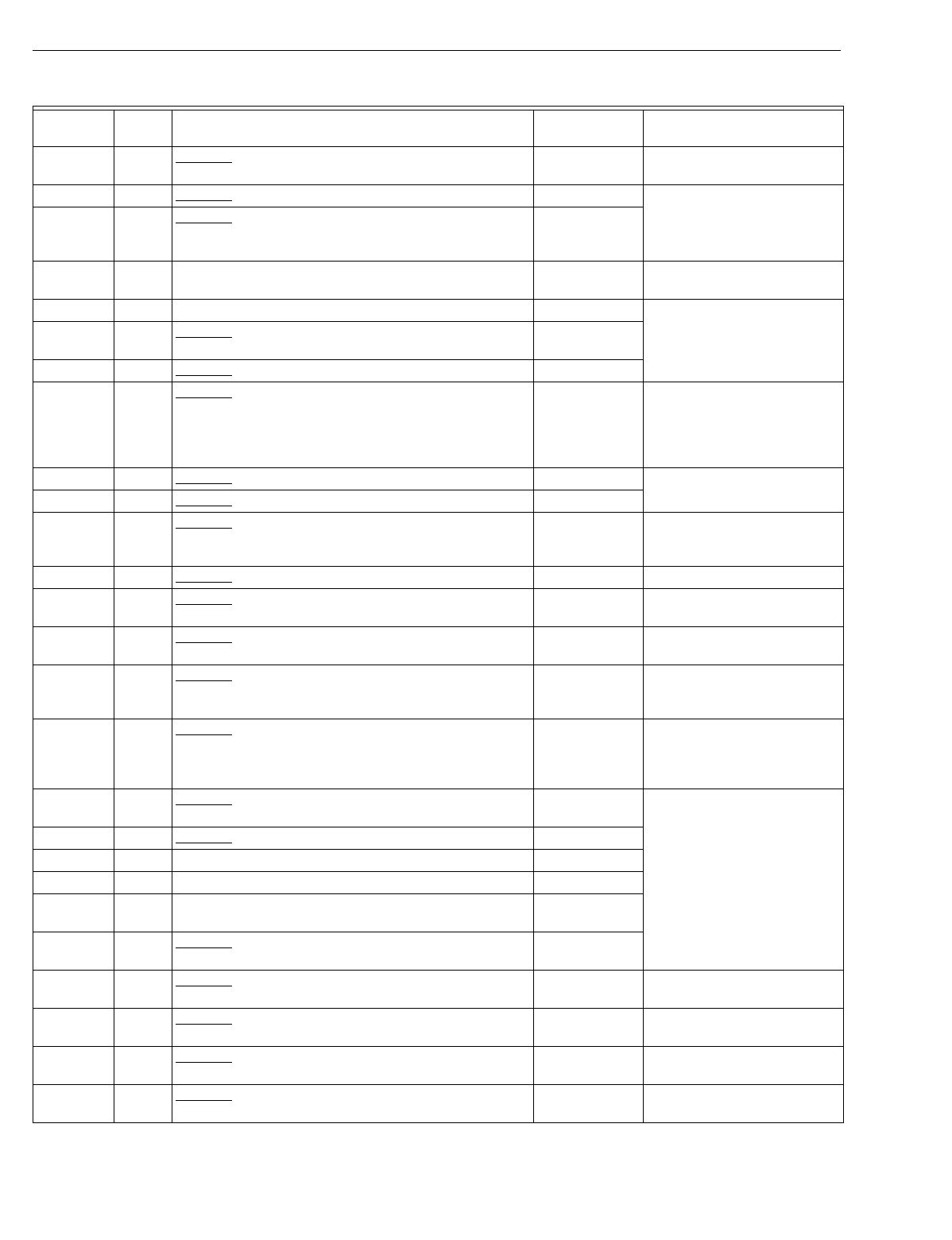
T874 MULTISTAGE THERMOSTATS AND Q674 SUBBASES
60-2485—854
D1470 44 Obsolete. York lo
g
o; part no. 2TH04701624A; includes
Allen wrench and screws to lock cover; °C scaleplate. T874D1165 Replacement has °F
scaleplate.
D1488 44 Obsolete. Risco special. T874D1165
D1496 44 Obsolete. Bor
g
Warner multi-lo
g
o; part no.
6TH04701524A; includes Allen wrench and screws to
lock cover.
T874D1165
D1504 82 York lo
g
o; part no. 025-23321-000; °C scaleplate; used
with Q674E1007; used in Y594D1180. T874D1165 Replacement has °F
scaleplate.
D1512 44 Hone
y
well lo
g
o; Heil Quaker part no. HQ712002HW. T874D1165
D1520 44 Obsolete. Bard lo
g
o; ad
j
ustable lever stops set 68°F
(
max. heat
)
and 78°F
(
min. cool
)
. T874D1165
D1538 44 Obsolete. McQua
y
lo
g
o; part no. 02005937. T874D1165
D1553 44 Obsolete. Climate Control special; part no. 02005944;
°C scaleplate; 6°C differential between H1 and H2; 3°C
differential between C1 and C2.
T874D1165 Replacement has 2°F
differential between H1 and
H2; 2°F differential between
C1 and C2; replacement has
°F scaleplate.
D1561 44 Obsolete. General Electric lo
g
o; used with Q674 A-G. T874D1165
D1587 44 Obsolete. Stiles Four Seasons lo
g
o. T874D1165
D1595 139 Obsolete. Nepco lo
g
o; used with Q674F1394. T874D1165/
Q674B1018a
Replacement has HEAT-OFF-
COOL s
y
stem switchin
g
; no
LEDs.
D1603 44 Obsolete. Arcoaire lo
g
o. T874D1165
D1611 44 Obsolete. No lo
g
o; Friedrich part no. AT5411; °F/°C
scaleplate. T874D1165 Replacement has °F
scaleplate.
D1629 82 Obsolete. Reznor lo
g
o; °F/°C scaleplate; used with
Q674E1007; used in Y594D1248. T874D1165 Replacement has °F
scaleplate.
D1678 44 Obsolete. Hone
y
well lo
g
o; Saudi O
g
er special; °C
scaleplate; one setpoint lever; used with Q674A-K. T874D1165 Replacement has °F
scaleplate; separate heatin
g
and coolin
g
setpoint levers.
D1686 98 Obsolete. McQua
y
lo
g
o; part no. 60685501; 8°F
(
4.4°C
)
differential between H1 and H2; 6°F
(
3.3°C
)
differential
between C1 and C2; used with Q674E1312.
T874D1165 Replacement has 2°F
differential between H1 and
H2; 2°F differential between
C1 and C2.
D1694 202 Obsolete. McQua
y
lo
g
o; part no. 60685201; used with
Q674G1120. See OEM for
replacement.
D1702 44 Obsolete. McQua
y
lo
g
o; part no. 60685101. T874D1165
D1710 44 Trane lo
g
o. T874D1165
D1728 44 York-Miraco lo
g
o. T874D1165
D1744 44 American Standard lo
g
o; heat anticipator factor
y
set at
0.4A. T874D1165
D1751 44 Obsolete. Goettl lo
g
o; part no. 372080; ran
g
e stops set
at 68°F
(
max. heatin
g)
and 78°F
(
min. coolin
g)
. T874D1165
D1769 82 Obsolete. Arcoaire lo
g
o; part no. 1506753; °F/°C
scaleplate; used with Q674E1346; used in Y594D1297. T874D1165 Replacement has °F
scaleplate.
D1777 44 Obsolete. Climate Control lo
g
o; part no. 65495806; °F/
°C scaleplate. T874D1165 Replacement has °F
scaleplate.
D1785 82 Obsolete. Comfortmaker lo
g
o; part no. 1505753; °F/°C
scaleplate; used with Q674E1346; used in Y594D1305. T874D1165 Replacement has °F
scaleplate.
D1793 44 Obsolete. McQua
y
lo
g
o; part no. 65495805; °F/°C
scaleplate. T874D1165 Replacement has °F
scaleplate.
Table 8. T874 Cross Reference.
Model
Number Fig.
No. Description Trade Model
Replacement Remarks
aBoth the thermostat and subbase must be replaced.
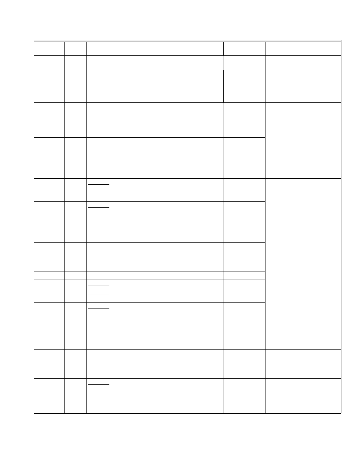
T874 MULTISTAGE THERMOSTATS AND Q674 SUBBASES
55 60-2485—8
D1801 45, 208 Trol-A-Temp b
y
Hone
y
well lo
g
o; H1 and H2 anticipators
set at 0.10A; used with Q674B1463, D1115. None See Trol-A-Temp for
replacement.
D1819 44 Marv Air Com Stat lo
g
o; part no. 50059; ad
j
ustable
intersta
g
e between H1 and H2 and between C1 and C2;
includes Allen wrench and screws to lock cover; field
ad
j
ustable ran
g
e stops; °F/°C scaleplate.
T874D1165 Replacement has a 2°F fixed
intersta
g
e differential between
H1 and H2 and between C1
and C2; replacement has °F
scaleplate.
D1827 45, 208 Trol-A-Temp b
y
Hone
y
well lo
g
o; Premier White® color;
H1 and H2 heat anticipators set at 0.10A; used with
Q674B1471, D1123.
None See Trol-A-Temp.
D1843 45 Obsolete. Janitrol lo
g
o; Goodman part no. CHT 90-120;
used with Q674B1000; used in Y594D1321. T874D1165
D1850 44 Hone
y
well lo
g
o; Carrier part no. HH621606. T874D1165
D1868 44 Bard lo
g
o; part no. 8405-031; H1 and H2 heat
anticipators factor
y
set at 0.25A; 5°F intersta
g
e
differential between H1 and H2 and between C1 and C2;
includes Allen wrench and screws to lock cover; field
ad
j
ustable ran
g
e stops.
T874D1165 Replacement has 2°F fixed
intersta
g
e differential between
H1 and H2 and between C1
and C2.
D1876 44 Obsolete. AAF/Sn
y
der General lo
g
o; part no.
4ELN6981A; °F/°C scaleplate. T874D1165 Replacement has °F
scaleplate.
D1892 44 Obsolete. Climate-Tel lo
g
o. T874D1165
D1918 224,
225 Obsolete. AAF/Sn
y
der General lo
g
o; °F/°C scaleplate;
no coolin
g
anticipation; used with Q674E1312, C1298;
66804407.
See OEM for
replacement.
D1926 226 Obsolete. AAF/Sn
y
der General lo
g
o; °F/°C scaleplate;
no coolin
g
anticipation; used with Q674G1120;
66804406.
See OEM for
replacement.
D1934 44 Bard lo
g
o. T874D1165
D1942 82 Hone
y
well lo
g
o; TRADELINE model; used with
Q674E1403; used in Y594D1347; desi
g
ned to replace
York part no. 2TH04701024.
Y594D1347a
D1959 44 Rheem part no. 41-21444-01. T874D1165
D1967 44 Obsolete. Desert Aire lo
g
o. T874D1165
D1975 224,
225 Obsolete. McQua
y
part no. 066816603; °F/°C
scaleplate; no coolin
g
anticipation. See OEM for
replacement.
D1983 226 Obsolete. McQua
y
part no. 066816602; °F/°C
scaleplate; no coolin
g
anticipation; used with
Q674G1120.
See OEM for
replacement.
D1991 51, 53 Carrier lo
g
o; Premier White® color; °C scaleplate. T874D1165aSet H1 anticipator for total
current draw of fan and sta
g
e
1 primar
y
; replacement has °F
scaleplate.
D2007 44 Ultra-Zone lo
g
o. T874D1165
D2023 44 Hone
y
well lo
g
o; TRADELINE model; Premier White®
color; °C scaleplate; includes lockin
g
cover; used with
Q674A-K.
T874D1165 Replacement has °F
scaleplate and is bei
g
e.
D2031 82 Obsolete. Hone
y
well lo
g
o; no cover; used with
Q674E1049 and TG504A1025; used in Y594D1354. T874D1165 or
Y594D1354
D2049 45, 72,
55, 66,
184
Obsolete. Carrier Heat Pump S
y
stem Control lo
g
o; part
no. HH07AT236; °F/°C scaleplate; used with Q674B-D,
Q674G; used in Y594D.
T874D1165 Replacement has °F
scaleplate.
Table 8. T874 Cross Reference.
Model
Number Fig.
No. Description Trade Model
Replacement Remarks
aBoth the thermostat and subbase must be replaced.
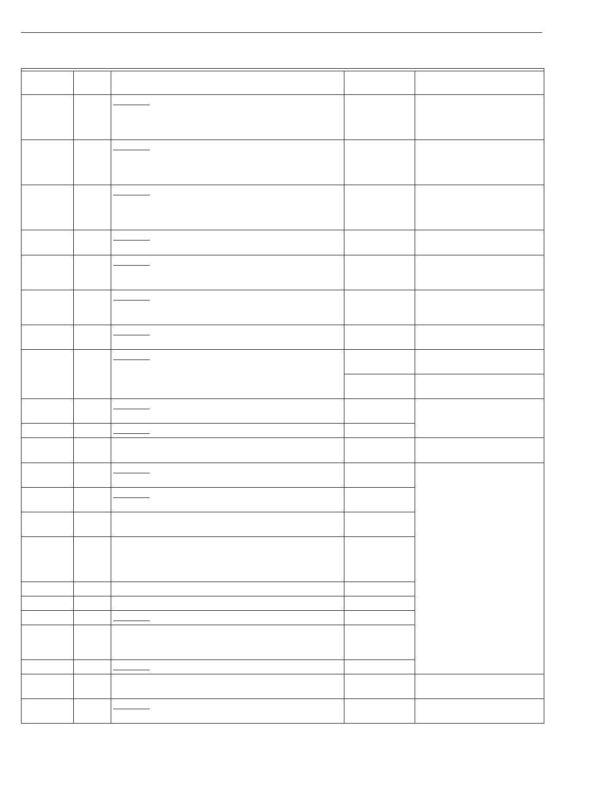
T874 MULTISTAGE THERMOSTATS AND Q674 SUBBASES
60-2485—856
D2056 44 Obsolete. ComStat lo
g
o; part no. 50056; °F/°C
scaleplate; ad
j
ustable intersta
g
e on both heatin
g
and
coolin
g
; includes lockin
g
cover and field-ad
j
ustable
lockin
g
levers.
T874D1165 Replacement has °F
scaleplate and 2°F fixed
differential in heatin
g
and
coolin
g
.
D2064 53 Obsolete. Carrier Weathermaker; part no. HH07AT209;
sta
g
e 1 and 2 heat anticipator factor
y
set 0.1A; taupe
color; used with Q674E1445; used in Y594D1412.
T874D1165 Set sta
g
e 1 heat anticipator for
total current draw of fan and
sta
g
e 1 heat primar
y
.
Replacement is bei
g
e.
D2072 53 Obsolete. Carrier Zone Perfect; part no. HH07AT208;
taupe color; used with Q674E1445; used in Y594D1420. T874D1165 Set sta
g
e 1 heat anticipator for
total current draw of fan and
sta
g
e 1 heat primar
y
.
Replacement is bei
g
e.
D2080 139 Obsolete. H
y
droheat lo
g
o. T874D1165/
Q674B1018a
Replacement s
y
stem switch:
HEAT-OFF-COOL; no LEDs.
D2098 44 Obsolete. Hone
y
well lo
g
o; °F scaleplate; one setpoint
lever; used with Q674D1008; used in Y594D1438. T874D1165 Replacement has °F
scaleplate and two setpoint
levers
D2106 44 Obsolete. Hone
y
well lo
g
o; °C scaleplate; one setpoint
lever; used with Q674D1008; used in Y594D1446. T874D1165 Replacement has °F
scaleplate and two setpoint
levers.
D2114 44 Obsolete. Bard lo
g
o; °C scaleplate. T874D1165 Replacement has °F
scaleplate.
D2122 224,
225 Obsolete. McQua
y
T874D2023 Replacement has °C
scaleplate.
T874D1165 Replacement has °F
scaleplate.
D2130 226 Obsolete. McQua
y
See OEM for
replacement.
D2148 44 Obsolete. Dr
y
Aire S
y
stems lo
g
o; °F/°C scaleplate. T874D1165
D2155 139 H
y
droheat lo
g
o; Premier White® color; °F/°C scaleplate;
used with Q674F1634. T874D1165/
Q674B1018a
Replacement s
y
stem switch:
HEAT-OFF-COOL; no LEDs.
D2163 208 Obsolete. Amana lo
g
o; part no. P1217501F; °F/°C
scaleplate. T874D1165
D2171 44 Obsolete. Amana lo
g
o; part no. P1217701F; °F/°C
scaleplate. T874D1942
D2189 44 Armstron
g
lo
g
o; part no. 01142A024; °F/°C scaleplate;
includes Air Ease insert. T874D1165
D2197 44 Liebert lo
g
o; part no. 138968P3; °F/°C scaleplate;
intersta
g
e differential between H1 and H2 and between
C1 and C2; includes Allen wrench and screws to lock
cover; field-ad
j
ustable lockin
g
levers.
T874D1165
D2205 44 Aaon lo
g
o; Premier White® color; °F/°C scaleplate. T874D1165
T874E 0-sta
g
e heat, 2-sta
g
e cool.
E1008 44 Obsolete. Hone
y
well lo
g
o. T874E1016
E1016 44 Hone
y
well lo
g
o; TRADELINE model; includes Allen
wrench and screws to lock cover; field-ad
j
ustable
lockin
g
levers.
T874E1016
E1024 44 Obsolete. Westin
g
house lo
g
o. T874E1016
E1032 44 Lennox lo
g
o; part no. 13F0901; °F/°C scaleplate. T874E1016 Replacement has °F
scaleplate.
E1040 72 Obsolete. Trane lo
g
o; used with Q674C1009; used in
Y594E1015. T874E1016
Table 8. T874 Cross Reference.
Model
Number Fig.
No. Description Trade Model
Replacement Remarks
aBoth the thermostat and subbase must be replaced.
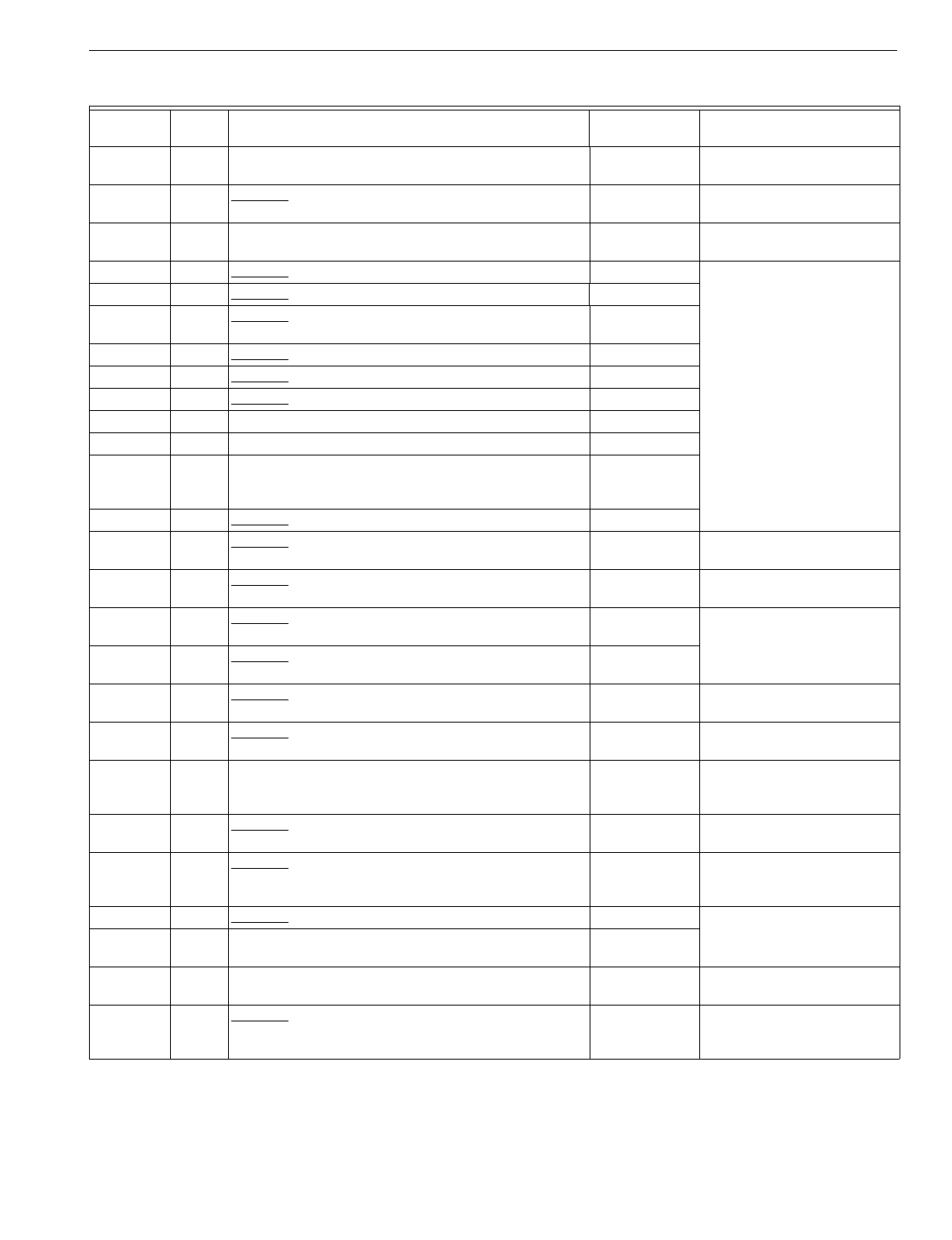
T874 MULTISTAGE THERMOSTATS AND Q674 SUBBASES
57 60-2485—8
E1081 44 Trane lo
g
o; part no. BAY28X186; °F/°C scaleplate. T874E1016 Replacement has °F
scaleplate.
E1099 44 Obsolete. Lennox lo
g
o; part no. 13F1001; °C scaleplate. T874E1016 Replacement has °F
scaleplate.
E1107 44 Hone
y
well lo
g
o; °C scaleplate. T874E1016 Replacement has °F
scaleplate.
E1123 44 Obsolete. Amana lo
g
o; part no. D68535-4. T874E1016
E1149 44 Obsolete. York lo
g
o; part no. 2TH04701724A. T874E1016
E1156 44 Obsolete. Bor
g
Warner multi-lo
g
o; part no.
6TH04701724A. T874E1016
E1164 44 Obsolete. E. A. Juffali & Bros. lo
g
o. T874E1016
E1206 44 Obsolete. Trane lo
g
o. T874E1016
E1230 44 Obsolete. Climar lo
g
o. T874E1016
T874F 2-sta
g
e heat, 0-sta
g
e cool.
F1007 44 Hone
y
well lo
g
o. T874F1015
F1015 44 Hone
y
well lo
g
o; TRADELINE model; includes Allen
wrench and screws to lock cover; field-ad
j
ustable
lockin
g
levers.
T874F1015
F1023 44 Obsolete. Lennox lo
g
o; part no. 13F1101. T874F1015
F1031 44 Obsolete. Hone
y
well lo
g
o; °C scaleplate; used with
40003440-001 wallplate; used in Y594F1022. T874F1015 Replacement has °F
scaleplate.
F1049 44 Obsolete. Lennox lo
g
o; °C scaleplate. T874F1015 Replacement has °F
scaleplate.
F1056 55,
66 Obsolete. Hone
y
well lo
g
o; sta
g
es 1 and 2 heat
electricall
y
isolated; used with Q674D1008. None
F1072 44 Obsolete. Wesco lo
g
o; heat anticipator factor
y
set at
0.8A. T874F1015
F1098 189 Obsolete. Lennox lo
g
o; used with Q674D1008 to control
an M839. T874F1015 Set H1 and H2 anticipators to
lowest settin
g
s.
F1106 95 Obsolete. Oneida lo
g
o; part no. 30A0287-02; used with
Q674K1018 on combination wood and oil applications. T874F1155
F1114 44 Hone
y
well lo
g
o; Hone
y
well Canada TRADELINE model;
°C scaleplate; includes Allen wrench and screws to lock
cover; field-ad
j
ustable lockin
g
levers.
T874F1015 Replacement has °F
scaleplate.
F1122 62 Obsolete. Hone
y
well lo
g
o; two heat setpoint levers;
used with Q674B1307. T874F1015/
Q674D1040 Replacement has no LED.
F1130 72, 91 Obsolete. Reznor lo
g
o; °F/°C scaleplate; used with
Q674C, D, or G; used with Q674C1009, G1005; used in
Y594F1048.
T874F1015 Replacement has °F
scaleplate.
F1148 44 Obsolete. Trane lo
g
o; part no. THT 0584. T874F1015
F1155 95 Hone
y
well lo
g
o; used with Q674K1026 on combination
wood and oil applications. T874F1155
T874G Heat pump models; 2-sta
g
e heat, 1-sta
g
e cool;
1–sta
g
e chan
g
eover.
G1006 84, 155 Obsolete. Hone
y
well lo
g
o; used with Q674E1015. Y594G1252aWirin
g
differences
(
old=new
)
:
R=O, M=Y, F=G, V=R, Y=W2;
E-W2
j
umper re
q
uired.
Table 8. T874 Cross Reference.
Model
Number Fig.
No. Description Trade Model
Replacement Remarks
aBoth the thermostat and subbase must be replaced.
T874 MULTISTAGE THERMOSTATS AND Q674 SUBBASES
60-2485—858
G1014 86, 150 Obsolete. Lennox lo
g
o; part no. 24F5801; °F/°C
scaleplate; H2 anticipator factor
y
set at 0.25A for fast
c
y
cle performance; chan
g
eover in coolin
g
mode;
independent heatin
g
and coolin
g
circuits; used with
Q674E1148, F1113.
Y594G1252aWirin
g
differences
(
old=new
)
:
R=O, M=Y, F=G, Y=W2,
V-VR=R
(
must use sin
g
le
transformer
)
.
G1022 86, 150 Obsolete. Lennox lo
g
o; part no. 24F5701; °F/°C
scaleplate; H2 anticipator factor
y
set at 0.25A for fast
c
y
cle performance; chan
g
eover in coolin
g
mode;
independent heatin
g
and coolin
g
circuits; used with
Q674E1148, F1113.
Y594G1252aWirin
g
differences
(
old=new
)
:
R=O, M=Y, F=G, Y=W2,
V-VR=R
(
must use sin
g
le
transformer
)
.
G1048 153,
159 Obsolete. Westin
g
house lo
g
o; H2 anticipator factor
y
set
at 1.2A; used with Q674F1121, J1019. Y594G1252aWirin
g
differences when
replacin
g
T874G/Q674J1019
(
old=new
)
: W=W2.
G1055 161 Carrier Heat Pump S
y
stem Control lo
g
o; part no.
HH07AT171; H2 anticipator factor
y
set at 0.8A;
chan
g
eover in coolin
g
mode; used with Q674J1035
(
HH93AZ173
)
.
None See subbase description for
replacement information.
G1071 50, 103,
126,
183
Obsolete. Carrier Heat Pump S
y
stem Control lo
g
o;
meets DoD specifications; H2 anticipator factor
y
set at
0.8A; used with Q674P1005
(
HH93AZ169
)
, L1041
(
HH93AZ175
)
, B1158, or J1050.
Y594G1419 Wirin
g
differences
(
old=new
)
:
C=X;
j
umper Y1-W1.
G1089 154 Obsolete. Marvair lo
g
o; special for Crispaire; H2
anticipator factor
y
set at 1.2A; used with Q674F1204;
used in Y594G1153.
Y594G1393aWirin
g
differences
(
old=new
)
:
A=L.
G1097 155 Obsolete. Hone
y
well lo
g
o; Rheem part no. ZXMT-B79;
used with Q674F1238
(
41-20797-14
)
. Y594G1252a
G1105 153 Obsolete. Heat Wave
(
Southwest Mf
g
.
)
lo
g
o; H2
anticipator factor
y
set at 1.2A; used with Q674F1170. Y594G1252a
G1113 103 Obsolete. Carrier Heat Pump S
y
stem Control lo
g
o;
meets DoD specifications; H2 anticipator factor
y
set at
0.8A; used with Q674L1041.
Y594G1419aWirin
g
differences
(
old=new
)
:
C=X;
j
umper Y1 -W1.
G1121 103 Obsolete. Carrier Heat Pump S
y
stem Control lo
g
o; part
no. HH07AT161; °C scaleplate; H2 anticipator factor
y
set at 0.8A; includes Allen wrench and screws to lock
cover.
Y594G1419aWirin
g
differences
(
old=new
)
:
C=X;
j
umper Y1-W1.
G1139 143,
234 Obsolete. Hone
y
well lo
g
o; used with Q674B1240,
C1108. None See subbase description for
replacement information.
G1147 148 Obsolete. Hone
y
well lo
g
o; chan
g
eover in coolin
g
mode;
used with Q674F1139. Y594G1252aWirin
g
differences
(
old=new
)
:
C=X.
G1154 84, 139 Obsolete. Lennox lo
g
o; used with Q674E1015, F1105. Y594G1252aSee subbase description for
replacement information.
G1162 155 Obsolete. Lennox lo
g
o; meets DoD specifications; used
with Q674F. Y594G1419aW1-Y1
j
umper re
q
uired.
G1170 160 Obsolete. York lo
g
o; part no. 2TH11702424A; H2
anticipator is fixed; used with Q674J1027; used in
Y594G1013.
Y594G1567a
G1188 147 Obsolete. Hone
y
well lo
g
o; Keeprite/Westin
g
house
special; H2 anticipator factor
y
set 1.2A; °C scaleplate;
chan
g
eover in coolin
g
mode; used with Q674F1295.
Y594G1252aWirin
g
differences
(
old=new
)
:
S=L.
G1196 160 Obsolete. York lo
g
o; °C scaleplate; chan
g
eover in
coolin
g
mode; used with Q674J1027; used in
Y594G1138.
Y594G1567a
Table 8. T874 Cross Reference.
Model
Number Fig.
No. Description Trade Model
Replacement Remarks
aBoth the thermostat and subbase must be replaced.
T874 MULTISTAGE THERMOSTATS AND Q674 SUBBASES
59 60-2485—8
G1204 162 Hone
y
well lo
g
o; desi
g
ned for use on Trane heat pumps;
no H2 anticipation; chan
g
eover in coolin
g
mode; used
with Q674J1043 and C815A1005; used in Y594G1161.
Y594G1161aDesi
g
ned for use on Trane
heat pumps.
G1212 155 Obsolete. Hone
y
well lo
g
o; H2 anticipator factor
y
set at
0.2A; chan
g
eover in coolin
g
mode; includes shunt to
b
y
pass H2 anticipator with W3 heat rela
y
s; used with
Q674F1238.
Y594G1252a
G1220 235 Obsolete. Rheem lo
g
o; part no. RXMT-C71; chan
g
eover
in coolin
g
mode; used with Q674F1238. Y594G1252a
G1238 155 Obsolete. Ruud lo
g
o; part no. UXMT-C71; chan
g
eover
in coolin
g
mode; used with Q674F1238. Y594G1252a
G1246 Obsolete. Hone
y
well lo
g
o; chan
g
eover in coolin
g
mode.
155 Used with Q674F1212; used in Y594G1195, G1252,
G1369. Y594G1252a
170 Used with Q674F1410; used in Y594G1393. Y594G1393a
G1261 58, 157 Obsolete. Bor
g
-Warner; used with Q674D1032, F1253. None See subbase description for
replacement information.
G1279 58, 157 Obsolete. Br
y
ant lo
g
o; used with Q674D1032, F1253. None See subbase description for
replacement information.
G1287 58, 157 Obsolete. Wesco lo
g
o; used with Q674D1032, F1253. None See subbase description for
replacement information.
G1295 58 Obsolete. York lo
g
o; part no. 2TH11702724A; used with
Q674D1032. T874D1165/
Q674D1040 Wirin
g
differences
(
old=new
)
:
Y=Y2, O=Y1, W=W2;
j
umper
W1-Y2.
G1345 160 Obsolete. York lo
g
o; part no. 2TH11702624A; °C
scaleplate; used with Q674J1027. Y594G1575a
G1352 73 Obsolete. Command-Aire lo
g
o; 12°F differential
between H1 and H2 for ni
g
ht setback; used with
Q674C1066.
Y594H1012aWirin
g
differences
(
old=new
)
:
Y1=O, Y2=Y, L=R, R=none; R-
L
j
umper re
q
uired; no ni
g
ht
setback.
T8600D1004
(
pro
g
rammable
)
Wirin
g
differences
(
old=new
)
:
Y1=O, Y2=Y, L=RH; RC-RH
j
umper re
q
uired; includes
ni
g
ht setback.
G1378 79 Obsolete. Mammoth lo
g
o; H2 anticipator factor
y
set at
0.8A; 12°F differential between H1 and H2 for ni
g
ht
setback; °F/°C scaleplate; used with Q674C1124; used
in Y594G1294.
Y594H1012aWirin
g
differences
(
old=new
)
:
R1=none, R2=L; R-L
j
umper
re
q
uired; no ni
g
ht setback.
T8090A1007/
Q682A1038a
(
pro
g
rammable
)
Includes ni
g
ht setback; W-Y
j
umper re
q
uired.
G1402 129 Obsolete. York part no. 2TH11702824A; meets DoD
specifications; used with Q674L1363. Y594R1425aWirin
g
differences
(
old=new
)
:
W=W2, X=E, B=X;
j
umper
Y-W1.
G1410 155 Obsolete. Bor
g
-Warner multi-lo
g
o; part
no. 6TH11703024A; used with Q674F1311. T874G1246a or
Y594G1252a
G1428 160 Obsolete. Bor
g
-Warner multi-lo
g
o; part no.
6TH11702424A; used with Q674J1027; used in
Y594G1229.
Y594G1567a
G1436 58 Obsolete. Bor
g
-Warner multi-lo
g
o; part no.
6TH11702724A. T874D1165/
Q674D1040 Wirin
g
differences
(
old=new
)
:
Y=Y2, O=Y1, W=W2;
j
umper
W1-Y2.
Table 8. T874 Cross Reference.
Model
Number Fig.
No. Description Trade Model
Replacement Remarks
aBoth the thermostat and subbase must be replaced.
T874 MULTISTAGE THERMOSTATS AND Q674 SUBBASES
60-2485—860
G1444 160 Obsolete. ROCA lo
g
o; °C scaleplate; used with
Q674J1027. Y594G1567a Replacement has °F
scaleplate.
G1451 155 Obsolete. BDP multi-lo
g
o; part no. HH641502; used with
Q674F1212; used in Y594G1245. T874G1246a or
V594G1252a
G1469 194 Obsolete. No lo
g
o; Addison special; used with
Q674F1345; used in Y594G1344. Y594G1252aWirin
g
differences
(
old=new
)
:
Y1=O, C=X, W1=Y1, X=L.
G1485 163 Obsolete. AAF lo
g
o; part no. 4ELN-7839; °F/°C
scaleplate; 10°F differential between H1 and H2 for ni
g
ht
setback and momentar
y
RESET s
y
stem switch position;
used with Q674C1199.
Y594G1393aNo ni
g
ht setback or
momentar
y
reset switch.
T8611G1004
(
pro
g
rammable
)
Includes ni
g
ht setback; no
momentar
y
reset switch.
G1493 167 Obsolete. Hone
y
well lo
g
o; Rheem part no. 41-20797-
18; used with Q674F1360. Y594G1526a
G1501 195 Obsolete. Coleman lo
g
o; part no. 3600-375; chan
g
eover
in coolin
g
mode; used with Q674F1378. Y594G1252aWirin
g
differences
(
old=new
)
:
L1=L; chan
g
eover in coolin
g
onl
y
.
G1535 163 Obsolete. AAF/Sn
y
der General lo
g
o; 4ELN7839 °F/°C
scaleplate; 10°F differential between H1 and H2 for ni
g
ht
setback and momentar
y
RESET s
y
stem switch position;
used with Q674C1199.
Y594G1393aNo ni
g
ht setback or
momentar
y
reset switch.
T8611G1004
(
pro
g
rammable
)
Includes ni
g
ht setback.
G1543 194 Obsolete. Addison lo
g
o; Weather Kin
g
part no. 8403-
197; used with Q674F1345; used in Y594G1328. Y594G1252aWirin
g
differences
(
old=new
)
:
Y1=O, C=X, W1=Y, X=L.
G1568 160 Obsolete. Luxaire lo
g
o; part no. 026-00068-000; °C
scaleplate; used with Q674J1126; used in Y594G1351. Y594G1367aReplacement has °F
scaleplate.
G1576 169 Obsolete. Coleman lo
g
o; part no. 3600-373; chan
g
eover
in heatin
g
and coolin
g
mode; used with Q674F1402;
used in Y594G1377.
Y594G1633a
G1584 73 Obsolete. No lo
g
o; Friedrich part no. AT5784; 8°F
(
4.4°C
)
differential between H1 and H2; used with
Q674C1223.
Y594H1012aWirin
g
differences
(
old=new
)
:
Y1=O, Y2=Y, L=R, R=none;
L-R
j
umper re
q
uired; no ni
g
ht
setback.
T8611G1004
(
pro
g
rammable
)
Includes ni
g
ht setback.
G1592 155 Obsolete. Arcoaire lo
g
o; used with Q674F1212; used in
Y594G1385. T874G1246a or
Y594G1252a
G1600 199 Obsolete. Hone
y
well lo
g
o; meets DoD specifications;
used with Q674F1428; used in Y594G1401. Y594G1419a Wirin
g
differences
(
old=new
)
:
j
umper W1-Y1.
G1618 73 Obsolete. Hone
y
well lo
g
o; 12°F differential between H1
and H2 for ni
g
ht setback; used with Q674C1256. Y594H1012aWirin
g
differences
(
old=new
)
:
Y1=O, Y2=Y, L=R, R=none;
L-R
j
umper re
q
uired; no ni
g
ht
setback.
T8600C1162
(
pro
g
rammable
)
Wirin
g
differences
(
old=new
)
:
L=R, W=O; W-Y
j
umper
re
q
uired; includes ni
g
ht
setback.
G1626 167 Hone
y
well lo
g
o; used with Q674F1436; used in
Y594G1526. None
G1642 227 Hone
y
well lo
g
o; TRADELINE model; meets DoD
specifications; used with Q674F1444; used in
Y594G1419.
Y594G1419a
Table 8. T874 Cross Reference.
Model
Number Fig.
No. Description Trade Model
Replacement Remarks
aBoth the thermostat and subbase must be replaced.
T874 MULTISTAGE THERMOSTATS AND Q674 SUBBASES
61 60-2485—8
G1659 177 Obsolete. Mammoth lo
g
o; 0.8A maximum current
throu
g
h B or O terminal; 12°F differential between H1
and H2 for ni
g
ht setback; used with Q674C1330; used in
Y594G1427.
Y594H1012aWirin
g
differences
(
old=new
)
:
R2=L, R1=none; L-R
j
umper
re
q
uired; no ni
g
ht setback.
T8611G1004
(
pro
g
rammable
)
Includes ni
g
ht setback.
G1675 174 Obsolete. American Standard lo
g
o; part no.
ASYSTAT650; used with Q674J1142; used in
Y594G1443.
Y594G1161a
G1691 176 Obsolete. Command Aire lo
g
o; part no. P1013-0060;
12°F
(
6.6°C
)
differential between H1 and H2 for ni
g
ht
setback; used with Q674C1389, C1397.
Y594H1012aWirin
g
differences
(
old=new
)
:
Y1=O, Y2=Y, R=none; L-R
j
umper re
q
uired; no ni
g
ht
setback.
T8611G1004
(
pro
g
rammable
)
Includes ni
g
ht setback.
G1717 175 Obsolete. Carrier Heat Pump S
y
stem Control lo
g
o; part
no. HH07AT102N; used with Q674J1167; used in
Y507J1201.
Y594G1252aWirin
g
differences
(
old=new
)
:
C=X, D=L; replacement has
AUX. HEAT and EM. HEAT
LEDs.
G1741 227 Hone
y
well lo
g
o; TRADELINE model; includes factor
y
set ran
g
e stops at 68°F
(
max. heat
)
and 78°F
(
min.
cool
)
; Premier White® color; used with Q674F1477;
used in Y594G1476.
Y594G1476a
G1758 211 Trol-A-Temp b
y
Hone
y
well lo
g
o; Premier White® color;
chan
g
eover is provided b
y
Trol-A-Temp zone panel;
used with Q674F1485; used in Y594G1492.
None See Trol-A-Temp for
replacement.
G1774 216 Obsolete. Comfortmaker lo
g
o; part no. 1505756; used
with Q674J1175; used in Y594G1500. Y594G1252aWirin
g
differences
(
old=new
)
:
E=W2, W1=W3, X=E, C=X.
G1782 216 Obsolete. Arcoaire lo
g
o; part no. 1506756; used with
Q674J1175; used in Y594G1518. Y594G1252aWirin
g
differences
(
old=new
)
:
E=W2, W1=W3, X=E, C=X.
G1790 161 Obsolete. Carrier lo
g
o; Premier White® color; °C
scaleplate; includes Allen wrench and screws to lock
cover; used with Q674J1191.
Y594G1252aWirin
g
differences
(
old=new
)
:
C=X; replacement has °F
scaleplate.
G1816 163 Climate Master lo
g
o; part no. AT5716; °F/°C scaleplate;
10°F differential between H1 and H2 and momentar
y
RESET s
y
stem switch position.
Y594G1393aNo momentar
y
reset switch.
G1824 227 Hone
y
well lo
g
o; Australian TRADELINE model; Premier
White® color; °C scaleplate; used with Q674F1477;
used in Y594G1534.
Y594G1476a
G1832 231 Obsolete. Intertherm lo
g
o; used with Q674F1519; used
in Y594G1542. Y594G1252aReplacement has auto
chan
g
eover in coolin
g
mode
onl
y
.
G1840 231 Obsolete. Miller lo
g
o; used with Q674F1519; used in
Y594G1559. Y594G1252aReplacement has auto
chan
g
eover in coolin
g
mode
onl
y
.
G1857 229 Obsolete. Lennox lo
g
o; °C scaleplate; Premier White®
color; used with Q674F1535; used in Y594G1583. Y594G1161aWirin
g
differences
(
old=new
)
:
E=X2, C=B, L=F.
G1865 160 Hone
y
well lo
g
o; TRADELINE model; desi
g
ned to
replace Y594G1013
(
York part no. 2TH11702424
)
,
Y594G1229
(
York part no. 6TH11702424
)
, and York part
no. 2TH117704124
)
; used with Q674J1209; used in
Y594G1567.
Y594G1567a
Table 8. T874 Cross Reference.
Model
Number Fig.
No. Description Trade Model
Replacement Remarks
aBoth the thermostat and subbase must be replaced.
T874 MULTISTAGE THERMOSTATS AND Q674 SUBBASES
60-2485—862
G1873 160 Obsolete. Hone
y
well lo
g
o; TRADELINE model; Premier
White® color; desi
g
ned to replace Y594G1013
(
York
part no. 2TH11702424
)
, Y594G1229
(
York part no.
6TH11702424
)
, and York part no. 2TH117704124
)
; used
with Q674J1225; used in Y594G1575.
Y594G1567aReplacement is bei
g
e.
G1881 167 Rheem; part no. 41-20797-18. Y594G1526a
G1899 169 Obsolete. Amana; part no. 10574101; used with
Q674F1550; used in Y594G1591. Y594G1633a
G1915 155 Econar lo
g
o; used with Q674F1212; used in
Y594G1609. Y594G1252a
170 Used with Q674F1410. Y594G1393a
G1923 176 Trane lo
g
o; part no. X13510599010; H2 make 12°F
below H1 make. Y594H1012aWirin
g
differences
(
old=new
)
:
Y1=O, Y2=Y, R=none; L-R
j
umper re
q
uired; no ni
g
ht
setback.
T8611G1004
(
pro
g
rammable
)
Includes ni
g
ht setback.
G1931 155,
170 Obsolete. Hone
y
well lo
g
o; Premier White® color; °C
scaleplate; used with Q674F1568. None See subbase description for
replacement information.
G1949 73 Obsolete. Carrier Heat Pump S
y
stem Control lo
g
o; part
no. HH07AT204; °F/°C scaleplate; H2 make 8°F below
H1 make; used in Y594.
Y594H1012aWirin
g
differences
(
old=new
)
:
Y1=O, Y2=Y, L=R, R=none; R-
L
j
umper re
q
uired; no ni
g
ht
setback.
T8600D1004
(
pro
g
rammable
)
Wirin
g
differences
(
old=new
)
:
Y1=O, Y2=Y, L=RH; RC-RH
j
umper re
q
uired; includes
ni
g
ht setback.
G1956 30, 103,
126,
183
Obsolete. Carrier lo
g
o; Canada; Premier White® color;
°C scaleplate; includes lockin
g
cover. Y594G1476 Replacement has °F
scaleplate.
G1964 160 York lo
g
o; Canada; Premier White® color; °C scaleplate;
used in Y594G1625. Y594G1575aReplacement has °F
scaleplate.
G1972 169 Hone
y
well lo
g
o; TRADELINE model; used with
Q674F1584; used in Y594G1633. Y594G1633a
G1980 169 Obsolete. Amana lo
g
o; part no. 10574103; used with
Q674F1600; used in Y594G1641. Y594G1633aWirin
g
differences
(
old=new
)
:
W3=W2.
G1998 155 Obsolete. Tempstar lo
g
o
(
Inter-Cit
y
Products
)
; used in
Y594G1658; used with Q674F1212. Y594G1252a
G2004 103 Hone
y
well lo
g
o; TRADELINE model; used with Q674L;
used in Y594G. Y594G1666
161 Used with Q674J1274; used in Y594G1674. Y594G1674
G2046 155,
170 WaterFurnace lo
g
o; part no. TA21H03; Premier White®
color; °F/°C scaleplate; used with Q674F1667; used in
Y594G1716.
Y594G1716
T874H Heat pump model; 1-sta
g
e heat, 1-sta
g
e cool,
1-sta
g
e chan
g
eover in cool.
H1005 74 Obsolete. Command Aire lo
g
o; used with Q674C1041. Y594H1012aWirin
g
differences
(
old=new
)
:
Y1=O, Y2=Y; L-R
j
umper
re
q
uired.
H1013 74 Obsolete. Friedrich part no. AT5813; °C scaleplate; used
with Q674C1041. Y594H1012aWirin
g
differences
(
old=new
)
:
Y1=O, Y2=Y; L-R
j
umper
re
q
uired; replacement has °F
scaleplate.
Table 8. T874 Cross Reference.
Model
Number Fig.
No. Description Trade Model
Replacement Remarks
aBoth the thermostat and subbase must be replaced.

T874 MULTISTAGE THERMOSTATS AND Q674 SUBBASES
63 60-2485—8
H1021 74 Obsolete. Friedrich Climate Master lo
g
o; part no.
AT5821; °F/°C scaleplate; used with Q674C1041. Y594H1012aWirin
g
differences
(
old=new
)
:
Y1=O, Y2=Y; L-R
j
umper
re
q
uired; replacement has °F
scaleplate.
H1039 79 Obsolete. Mammoth lo
g
o; °F/°C scaleplate; used with
Q674C1124; used in Y594H1004. Y594H1012aWirin
g
differences
(
old=new
)
:
R1=R, R2=L.
H1054 74 Obsolete. No lo
g
o; Friedrich part no. AT5854; used with
Q674C1041. Y594H1012aWirin
g
differences
(
old=new
)
:
Y1=O, Y2=Y; L-R
j
umper
re
q
uired.
H1062 164 Hone
y
well lo
g
o; used with Q674C1249; used in
Y594H1012. Y594H1012a
H1070 172,
173 Obsolete. Carrier Heat Pump S
y
stem Control lo
g
o; part
no. HH07AT166; °C scaleplate; used with Q674B1406
(
HH93AZ200
)
or Q674C1322
(
HH93AZ199
)
.
None See subbase description for
replacement information.
H1088 172,
173 Obsolete. Carrier Heat Pump S
y
stem Control lo
g
o; part
no. HH07AT167; used with Q674B1406
(
HH93AZ200
)
or Q674C1322
(
HH93AZ199
)
.
None See subbase description for
replacement information.
H1096 177 Obsolete. Mammoth Water Source Heat Pump lo
g
o; °F/
°C scaleplate; chan
g
eover sta
g
e 0.8A maximum; used B
or O terminal; used with Q674C1330.
Y594H1012aWirin
g
differences
(
old=new
)
:
R1=R, R2=L; L-R
j
umper
re
q
uired.
H1112 74 No lo
g
o; Friedrich part no. AT5812; used with
Q674C1355. Y594H1012aWirin
g
differences
(
old=new
)
:
Y1=O, Y2=Y; L-R
j
umper
re
q
uired.
H1120 205 Obsolete. Command Aire lo
g
o; part no. P1013-0055;
used with Q674C1389, C1397. Y594H1012aWirin
g
differences
(
old=new
)
:
Y1=O, Y2=Y.
H1138 221 Obsolete. Climate Master lo
g
o; part no. AT5838; used
with Q674C1470. Y594H1012aWirin
g
differences
(
old=new
)
:
Y1=O, Y2=Y; replacement has
MALFUNCTION LED onl
y
.
H1146 205 Trane lo
g
o; part no. X13510598010. Y594H1012aWirin
g
differences
(
old=new
)
:
Y1=O, Y2=Y.
H1153 173 Obsolete. Carrier Heat Pump S
y
stem Control lo
g
o; part
no. HH07AT167; °F/°C scaleplate; used with
Q674C1322; used in Y594H1053.
None See subbase description for
replacement information.
H1161 74 Obsolete. Carrier Heat Pump S
y
stem Control lo
g
o; part
no. HH07AT203; °F/°C scaleplate; used with
Q674C1496; used in Y594H1038.
Y594H1012aWirin
g
differences
(
old=new
)
:
Y1=O, Y2=Y; L-R
j
umper
re
q
uired.
T874J Heat pump model. 2-sta
g
e heat, 1-sta
g
e cool.
J1002 124,
144,
206,
207
Obsolete. Carrier Heat Pump S
y
stem Control lo
g
o; part
no. HH07AT175; used with Q674J1068
(
HH93AZ183
)
,
Q674J1159
(
HH93AZ196
)
, Q674L1074
(
HH93AZ186
)
,
Q674L1637
(
HH93AZ195
)
.
None See subbase description for
replacement information.
J1010 124,
171 Obsolete. BDP multi lo
g
o; part no. 34427DP124/P272-
2471; used with Q674J1084, L1371. None See subbase description for
replacement information.
J1028 124,
144,
206,
207
Obsolete. Carrier Heat Pump S
y
stem Control lo
g
o; part
no. HH07AT165; °C scaleplate; used with Q674J1068
(
HH93AZ183
)
, Q674J1159
(
HH93AZ196
)
, Q674L1074
(
HH93AZ186
)
, Q674L1637
(
HH93AZ195
)
.
None See subbase description for
replacement information.
J1036 124,
171 Obsolete. Miller lo
g
o; part no. 9132230; used with
Q674J1217. T8511G1021
J1044 124,
171 Obsolete. Intertherm lo
g
o; part no. 9132240; used with
Q674J1217. T8511G1021
J1051 124,
144 Obsolete. Carrier lo
g
o; part no. HH07AT165-W; Premier
White® color; °C scaleplate. None See subbase description for
replacement information.
Table 8. T874 Cross Reference.
Model
Number Fig.
No. Description Trade Model
Replacement Remarks
aBoth the thermostat and subbase must be replaced.
T874 MULTISTAGE THERMOSTATS AND Q674 SUBBASES
60-2485—864
J1069 124,
144,
206,
207
Obsolete. Hone
y
well lo
g
o; TRADELINE model; used
with Q674J1282; used in Y594J1019. T8511G1021
J1077 124,
171 Obsolete. Nord
y
ne lo
g
o; part no. 9148300; °F/°C
scaleplate. T8511G1021
T874K Heat pump model; 2-sta
g
e heat, 1-sta
g
e cool, automatic
chan
g
eover in heat.
K1001 77 Obsolete. LSI Mammoth lo
g
o; used with Q674C1090. Y594G1419aWirin
g
differences
(
old=new
)
:
RH-RC=R, W1=B, W3=W2,
W2=W1; remove Y1-W1
j
umper.
K1019 181 Obsolete. McQua
y
/Sn
y
der General lo
g
o; part no.
60687301; °F/°C scaleplate; H1 anticipator set at 0.83A;
8°F intersta
g
e differential between H1 and H2 for ni
g
ht
setback; used with Q674C1280.
Y594G1252aWirin
g
differences
(
old=new
)
:
C=X, W=B, A=L;
j
umper
E-W2; no ni
g
ht setback.
T8611G1004
(
pro
g
rammable
)
Wirin
g
differences
(
old=new
)
:
C=X, W=B, A=X2;
j
umper X2-
R; remove external time clock;
includes ni
g
ht setback.
K1027 181 Obsolete. AAF/Sn
y
der General lo
g
o; part no.
066804403; °F/°C scaleplate; H1 anticipator set at
0.83A; 8°F intersta
g
e differential between H1 and H2 for
ni
g
ht setback; used with Q674C1280.
Y594G1252aWirin
g
differences
(
old=new
)
:
C=X, W=B, A=L;
j
umper
E-W2; no ni
g
ht setback.
T8611G1004
(
pro
g
rammable
)
Wirin
g
differences
(
old=new
)
:
C=X, W=B, A=X2;
j
umper
X2-R; remove external time
clock; includes ni
g
ht setback.
T874L Heat pump model; 2-sta
g
e heat, 1-sta
g
e cool,
chan
g
eover in cool.
L1000 198 Obsolete. Carrier lo
g
o; part no. HH07AT176; used with
Q674E1270
(
HH93AZ189
)
. Y594G1419aE-W2
j
umper re
q
uired.
L1018 138,
165 Obsolete. Carrier Multiplex S
y
stem lo
g
o; part no.
HH07AT178; used with Q674B1356
(
HH93AZ192
)
or
Q674C1264
(
HH93AZ193
)
.
See OEM for
replacement.
L1026 198 Obsolete. Hone
y
well lo
g
o; BDP part no. P272-2786;
used with Q674E1304. Y594G1419aE-W2
j
umper re
q
uired.
L1034 203 Obsolete. McQua
y
lo
g
o; part no. 60687201; °F/°C
scaleplate; H1 anticipator factor
y
set at 0.83A; used with
Q674C1280.
Y594G1419aWirin
g
differences
(
old=new
)
:
Y=Y1, W=B, A=X1; remove
Y1-W1
j
umper.
L1059 215,
213 Obsolete. Carrier lo
g
o; part no. HH07AT192; used with
Q674B1448
(
HH93A2202
)
or Q674C1413
(
HH93AZ204
)
.
See OEM for
replacement.
L1067 203 Obsolete. AAF/Sn
y
der General lo
g
o; part no.
066804402; H1 anticipator factor
y
set at 0.83A; used
with Q674C1280.
Y594G1419a Wirin
g
differences
(
old=new
)
:
Y=Y1, W=B, A=X1; remove
Y1-W1
j
umper.
L1075 203 Obsolete. McQua
y
lo
g
o; part no. 073318601; Premier
White® color; °F/°C scaleplate; includes AAF insert. See OEM for
replacement.
T874N Heat pump model; 2-sta
g
e heat; 1-sta
g
e cool plus
chan
g
eover; chan
g
eover in heat mode.
N1008 178 Obsolete. Williamson lo
g
o; used with Q674F1196; used
in Y594N1007. T874N1016
N1016 178 Hone
y
well Heat Pump Thermostat lo
g
o; used with
Q674F1220. T874N1016
N1024 179,
217 Bard lo
g
o; H1 and C1 anticipation fixed; used with
Q674F1261. None See subbase description for
replacement information.
Table 8. T874 Cross Reference.
Model
Number Fig.
No. Description Trade Model
Replacement Remarks
aBoth the thermostat and subbase must be replaced.
T874 MULTISTAGE THERMOSTATS AND Q674 SUBBASES
65 60-2485—8
N1040 179 Obsolete. Hone
y
well lo
g
o; H1 and C1 anticipation fixed;
used with Q674F1261; used in Y594N1015. None
N1057 178 Obsolete. Intertherm lo
g
o; part no. 9111882; used with
Q674F1220; used in Y594N1023. T874N1016
N1065 178 Obsolete. Miller lo
g
o; Nord
y
ne part no. 9122240; used
with Q674F1220; used in Y594N1031. T874N1016
T874P Heat pump model; 2-sta
g
e heat, 1-sta
g
e cool, automatic
chan
g
eover in cool.
P1006 57, 78 Obsolete. McQua
y
lo
g
o; part no. 860-442725B-00; 8°F
(
4.4°C
)
intersta
g
e differential between H1 and H2; used
with Q674B1273, C1140.
None See subbase description for
replacement information.
P1014 78 Obsolete. Friedrich/Climate Master lo
g
o; °F/°C
scaleplate; 8°F
(
4.4°C
)
differential between H1 and H2
for ni
g
ht setback; used with Q674C1207.
T8600D2028
(
pro
g
rammable
)
Wirin
g
differences
(
old=new
)
:
L=R, W=O; W-Y
j
umper
re
q
uired; includes ni
g
ht
setback.
P1022 97 Obsolete. Friedrich/Climate Master lo
g
o; part no.
AT5922; °F/°C scaleplate; 8°F
(
4.4°C
)
differential
between H1 and H2 for ni
g
ht setback; used with
Q674C1215.
None See subbase description for
replacement information.
P1030 97 Obsolete. No lo
g
o; Friedrich part no. AT5930; 8°F
(
4.4°C
)
differential between H1 and H2 for ni
g
ht setback;
used with Q674C1215.
None See subbase description for
replacement information.
P1055 68, 97 Obsolete. Carrier Heat Pump S
y
stem Control lo
g
o; part
no. HH07AT205; °F/°C scaleplate; heat intersta
g
e
differential 8°F
(
4.4°C
)
.
None See subbase description for
replacement information.
T874Q 1-sta
g
e heat; used with another T874 for ni
g
ht setback.
Q1005 44 Hone
y
well lo
g
o. T874A1036
Q1013 44 Obsolete. Lennox lo
g
o; part no. 13F1201; °F/°C
scaleplate. T874A1036 Replacement has °F
scaleplate.
Q1021 44 Obsolete. Lennox lo
g
o; part no. 13F1301; °C scaleplate. T874A1036 Replacement has °F
scaleplate.
T874R Heat pump model; 2-sta
g
e heat, 1-sta
g
e cool, manual
chan
g
eover.
R1004 47 Obsolete. Hone
y
well lo
g
o; used with Q674B1042; used
in Y594R1029. Y594R1243aWirin
g
differences
(
old=new
)
:
W1=W2.
R1012 47 Obsolete. Hone
y
well lo
g
o; Addison heat pump; used
with Q674B1109. Y594R1243aWirin
g
differences
(
old=new
)
:
W1=W2.
R1020 102 Obsolete. Lennox lo
g
o; part no. 24F5401; °F/°C
scaleplate; H1 and C1 anticipators are fixed; auxiliar
y
heat circuit powered b
y
separate transformer; used with
Q674L1025.
Y594R1243a Wirin
g
differences
(
old=new
)
:
M=Y, F=G, V-VR=R, Y=W2,
R=O; replacement has °F
scaleplate.
R1038 102 Obsolete. Lennox lo
g
o; °C scaleplate; H1 and C1
anticipators are fixed; auxiliar
y
heat circuit powered b
y
separate transformer; used with Q674L1025.
Y594R1243aWirin
g
differences
(
old=new
)
:
M=Y, F=G, V-VR=R, Y=W2,
R=O; replacement has °F
scaleplate.
R1046 120,
101 Obsolete. York lo
g
o; part no. 2TH11702224A; H2
anticipator is fixed; used with Q674L1272 in Y594R1011
or with Q674L1094.
Y594R1664a
R1053 109 Obsolete. Hone
y
well lo
g
o; H2 anticipator is fixed; used
with Q674L1140; used in Y594R1136. Y594R1763aDesi
g
ned for use on Trane
heat pumps.
R1061 104 Obsolete. Hone
y
well lo
g
o; H2 anticipator is field
ad
j
ustable; chan
g
eover in coolin
g
; used with
Q674L1082.
Y594R1243aReplacement has auto fan in
Emer
g
enc
y
Heat mode.
Table 8. T874 Cross Reference.
Model
Number Fig.
No. Description Trade Model
Replacement Remarks
aBoth the thermostat and subbase must be replaced.
T874 MULTISTAGE THERMOSTATS AND Q674 SUBBASES
60-2485—866
R1079 123 Obsolete. Ruud lo
g
o; part no. UXMT-C70; used with
Q674L1157. Y594R1243a
R1087 120 Obsolete. Hone
y
well lo
g
o; Special for Dunham Bush;
use with Q674L. Y594R1664a
R1095 123 Obsolete. Rheem lo
g
o; part no. RXMT-C70; used with
Q674L1157. T874R1152/
Y594R1243a
R1103 104 Obsolete. Westin
g
house lo
g
o; used with Q674L. Y594R1243a
R1111 116,
104 Obsolete. Marvair lo
g
o; H2 anticipator factor
y
set at
1.2A; used with Q674L1215, L1082; used in
Y594R1128.
Y594R1243aReplacement has auto fan in
Emer
g
enc
y
Heat mode.
R1129 113 Bard lo
g
o; used with Q674L1181. Y594R1243aWirin
g
differences
(
old=new
)
:
X1=X.
R1137 108,
125 Obsolete. Hone
y
well lo
g
o; Heil Quaker part no.
HQ711597HW; used with Q674L1132; used in
Y594R1110.
Y594R1292a
R1145 120 Obsolete. York lo
g
o; °C scaleplate; H2 anticipator is
fixed; used with Q674L1272; used in Y594R1102. Y594R1664a
R1152 115 Hone
y
well lo
g
o; used with Q674L1207, L1033; used in
Y594R1243. Y594R1243a
R1160 182 Obsolete. Hone
y
well Advanced Heat Pump S
y
stem
lo
g
o; used with Q674L1298 and W89. None
R1178 110,
111 Obsolete. Lennox lo
g
o; part no. 24F5601; °F/°C
scaleplate; auxiliar
y
heat circuit powered b
y
separate
transformer; fast c
y
cle sta
g
e H2 anticipator; re
q
uires
outdoor reset and independent circuits; used with
Q674L1165, L1355.
Y594R1763aWirin
g
differences
(
old=new
)
:
V-VR=R, M=Y, F=G, X=B,
Y=W, A=T, R=O, E=X2.
R1186 182 Obsolete. Hone
y
well Advanced Heat Pump S
y
stem
lo
g
o; used with Q674L1231 and W89. None
R1194 115 Obsolete. Amana lo
g
o; used with Q674L1249 and W89. Y594R1243a
R1202 201 Obsolete. Intertherm lo
g
o; part no. 9111871; used with
Q674L1264 or Q674L1595; used in Y594R1185. Y594R1672aWirin
g
differences
(
old=new
)
:
W2=W, Z=no connection,
K=X, W=G, W1=H, X=B.
R1210 101 Obsolete. Roca lo
g
o; °C scaleplate; used with
Q674L1017. Y594R1243aWirin
g
differences
(
old=new
)
:
W=W2, X=L, B=X.
R1228 120 Obsolete. York lo
g
o; part no. 2TH11702524A; °C
scaleplate; used with Q674L1272 and C815A1005;
used in Y594R1144.
Y594R1672a
R1236 115 Obsolete. Williamson lo
g
o; includes Allen wrench and
screws to lock cover; used with Q674L1348. T874R1152
R1244 115 Obsolete. Westin
g
house lo
g
o; used with Q674L1314
and W89. T874R1152/
Y594R1243a
R1251 120 Obsolete. York lo
g
o; part no. 2TH11702324A; H2
anticipator is fixed; used with Q674L1272 and
C815A1039.
Y594R1672a
R1269 122 Obsolete. Fedders multi lo
g
o; part no.
THTX-120-HEHB 88-58-00540-001; used with
Q674L1066; used in Y594R1037.
Y594R1615aWirin
g
differences
(
old=new
)
:
K=E, C=X, W1=B, Z=L.
R1285 123 Obsolete. Hone
y
well lo
g
o; Rheem part no. 41-20796-
15; used with Q674L1157. Y594R1243a
R1301 113 Obsolete. Comfortmaker lo
g
o; part no. 1505-714; used
with Q674L1181; used in Y594R1417. Y594R1243aWirin
g
differences
(
old=new
)
:
X1=X.
Table 8. T874 Cross Reference.
Model
Number Fig.
No. Description Trade Model
Replacement Remarks
aBoth the thermostat and subbase must be replaced.
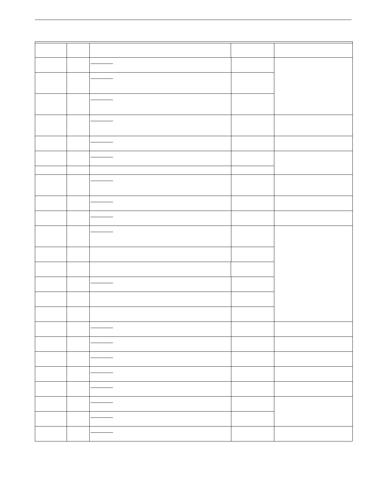
T874 MULTISTAGE THERMOSTATS AND Q674 SUBBASES
67 60-2485—8
R1319 191 Obsolete. Carrier part no. 42QH400083; used with
Q674B1281 on two speed fan applications. See OEM for
replacement.
R1327 120 Obsolete. Bor
g
-Warner multi-lo
g
o; part no.
6TH11702224A; used with Q674L1272; used in
Y594R1193.
Y594R1672a
R1335 106 Obsolete. BDP multi-lo
g
o; part no. HH641501; H2
anticipator factor
y
set 1.2A; used with Q674L1405; used
in Y594R1201.
Y594R1243a
R1343 133 Obsolete. Fedders multi-lo
g
o; part no.
THTX-120-HEHC 88-58-0056-001; used with
Q674L1413; used in Y594R1219.
Y594R1425aWirin
g
differences
(
old=new
)
:
K=E, C=X1, Z=L; remove
Y1-W1
j
umper.
R1350 113 Obsolete. Hone
y
well lo
g
o; used with Q674L1181. Y594R1243aWirin
g
differences
(
old=new
)
:
X1=X.
R1368 125 Obsolete. Coleman lo
g
o; part no. 3600-368; used with
Q674L1421; used in Y594R1235. Y594R1797a
R1376 115 Hone
y
well lo
g
o; °C scaleplate; used with Q674L1207. T874R1152
R1384 131,
135 Obsolete. Carrier Heat Pump S
y
stem Control lo
g
o; part
no. HH07AQ170; used with Q674L
(
HH93AZ187
)
,
Q674L
(
HH93AZ197
)
, or Q674L
(
HH93AZ198
)
.
Y594G1243aWirin
g
differences
(
old=new
)
:
C=X.
R1392 128 Obsolete. Williamson lo
g
o; used with Q674L1447; used
in Y594R1250. Y594R1425aWirin
g
differences
(
old=new
)
:
A=L.
R1400 113 Obsolete. LSI part no. 104710001; used with
Q674L1181, L1462. See subbase description for
replacement information.
R1426 136 Obsolete. Trane Weathertron Heat Pump lo
g
o; part no.
BAYSTAT339
(
WY28X0112
)
; °F/°C scaleplate; used
with Q674L1496; used in Y594R1284.
Y594R1763a
R1434 134 Ruud lo
g
o; part no. 41-20796-32; used with Q674L1504;
used in Y594R1649. Y594R1300a
R1442 134 Rheem lo
g
o; part no. 41-20796-28; used with
Q674L1504; used in Y594R1631. Y594R1300a
R1459 134 Obsolete. Hone
y
well lo
g
o; Rheem part no. 41-20796-
25; used with Q674L1504. Y594R1300a
R1467 108 Hone
y
well lo
g
o; used with Q674L1512; used in
Y594R1292. Y594R1292a
R1475 123 Hone
y
well lo
g
o; scale ran
g
e 42°F to 88°F; used with
Q674L1520; used in Y594R1300. Y594R1300a
R1483 130 Obsolete. Comfortmaker lo
g
o; °F/°C scaleplate; used
with Q674L1538 and C815A1005; used in Y594R1318. Y594R1763aWirin
g
differences
(
old=new
)
:
W1=W, E=X2, X=F, C=B.
R1491 137 Obsolete. Hone
y
well lo
g
o; TRADELINE model; used
with Q674L1553; used in Y594R1326. Y594R1615a
R1509 47 Obsolete. Slant/Fin lo
g
o; used with Q674B1042; used in
Y594R1334. Y594R1243aWirin
g
differences
(
old=new
)
:
W1=W2.
R1517 130 Obsolete. Arcoaire lo
g
o; part no. 150671; used with
Q674L1538 and C815A1005; used in Y594R1342. Y594R1763aWirin
g
differences
(
old=new
)
:
W1=W, E=X2, X=F, C=B.
R1525 113 Obsolete. Arcoaire lo
g
o; used with Q674L1181; used in
Y594R1359. Y594R1243aWirin
g
differences
(
old=new
)
:
X1=X.
R1541 67 Obsolete. Goettl lo
g
o; part no. 372071; used with
Q674B1349. Y594R1300a
R1558 134 Obsolete. Universal Parts lo
g
o; part no. 41-20796-45;
used with Q674L1504; used in Y594R1623. Y594R1300a
R1566 130 Obsolete. Hone
y
well lo
g
o; used with Q674L1538 and
C815A1005; used in Y594R1375. Y594R1763aWirin
g
differences
(
old=new
)
:
W1=W, E=X2, X=F, C=B.
Table 8. T874 Cross Reference.
Model
Number Fig.
No. Description Trade Model
Replacement Remarks
aBoth the thermostat and subbase must be replaced.
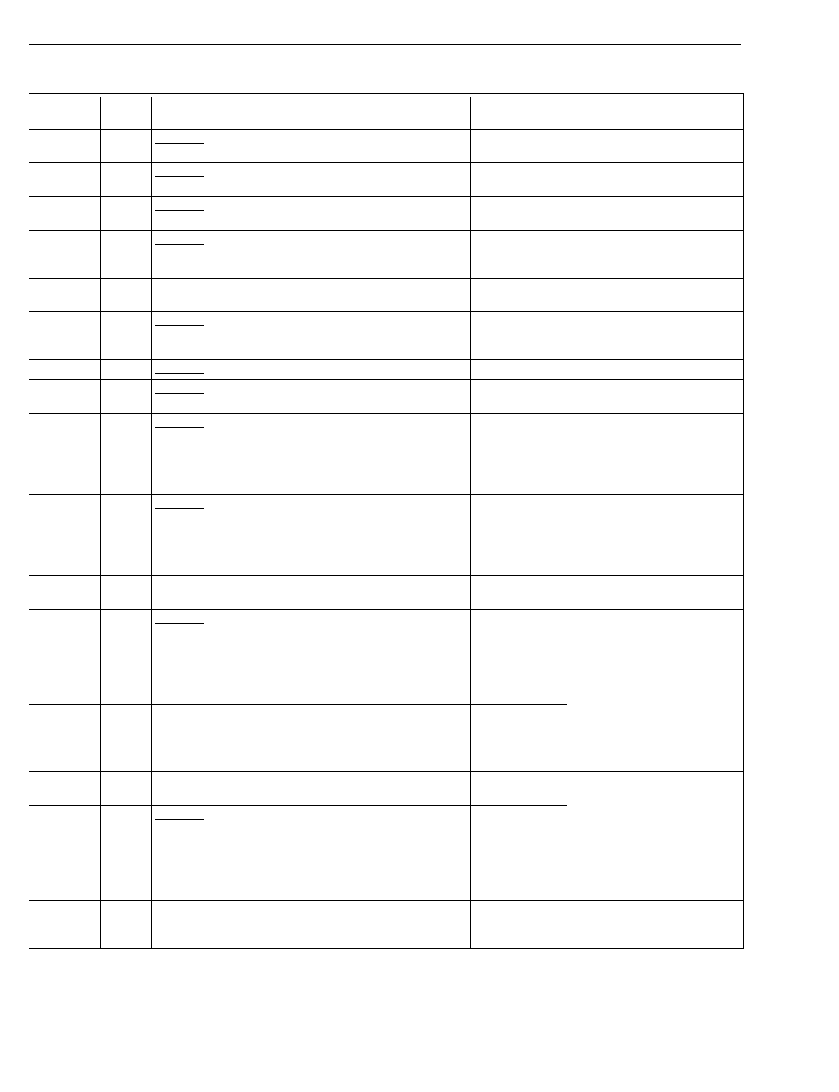
T874 MULTISTAGE THERMOSTATS AND Q674 SUBBASES
60-2485—868
R1574 132 Obsolete. Comfortmaker lo
g
o; part no. 1505739; used
with Q674L1538; used in Y594R1383. Y594R1243aWirin
g
differences
(
old=new
)
:
C=X, X=L, W=W2.
R1582 132 Obsolete. Arcoaire lo
g
o; part no. 150739; used with
Q674L1538; used in Y594R1391. Y594R1243aWirin
g
differences
(
old=new
)
:
C=X, X=L, W=W2.
R1590 115 Obsolete. Refac lo
g
o; used with Q674L1207. T874R1152/
Y594R1243a
Replacement has °F
scaleplate.
R1608 119 Obsolete. Hone
y
well lo
g
o; Intertherm heat pump; used
with Q674L1264; used in Y594R1409. Y594R1763aWirin
g
differences
(
old=new
)
:
W2=W, X=B, Z=F, K=X2,
W1=O.
R1616 168 Hone
y
well lo
g
o; SUPER TRADELINE® model; used
with Q674L1587; used in Y594R1425. Y594R1425a
R1624 200 Obsolete. Hone
y
well lo
g
o; used with Q674L1595; used
in Y594R1433. Y594R1243aWirin
g
differences
(
old=new
)
:
X=B, Z=F, W2=W, K=X2,
W1=O.
R1632 134 Obsolete. Hone
y
well lo
g
o; used with Q674L1603. Y594R1243a
R1640 115 Obsolete. Hitecsa lo
g
o; °C scaleplate; H2 anticipator
factor
y
set at 1.2A; used with Q674L1207. Y594R1243aReplacement has °F
scaleplate.
R1657 136 Obsolete. American Standard lo
g
o; part no.
ASYSTAT651; re
q
uires outdoor reset; used with
Q674L1611; used in Y594R1441.
Y594R1763a
R1673 108 Heil lo
g
o; part no. 1060321, HAXB004TW01; used with
Q674L1132; used in Y594R1466. Y594R1292a
R1699 119 Obsolete. Miller lo
g
o; used with Q674L1264; used in
Y594R1482. Y594R1763aWirin
g
differences
(
old=new
)
:
W2=W, X=B, Z=F, K=X2,
W1=O.
R1707 209 Trol-A-Temp b
y
Hone
y
well lo
g
o; Premier White® color;
used with Q674L1678; used in Y594R1490. None See Trol-A-Temp for
replacement.
R1715 209 Trol-A-Temp b
y
Hone
y
well lo
g
o; used with Q674L1186;
used in Y594R1508. None See Trol-A-Temp for
replacement.
R1723 218 Obsolete. No lo
g
o; Sn
y
der General part no. 654958B07;
°F/°C scaleplate; used with Q674L1702 and
C815A1005; used in Y594R1516.
Y594R1672aWirin
g
differences
(
old=new
)
:
W1=W, X=X2, C=B.
R1731 108 Obsolete. Inter-Cit
y
Products lo
g
o; part no.
HQ11477909HW; used with Q674L1132; used in
Y594R1524.
Y594R1292a
R1749 108 Tempstar lo
g
o; part no. 1060322, TAXB004TW01; used
with Q674L1132; used in Y594R1532. Y594R1292a
R1814 108 Obsolete. Hone
y
well lo
g
o; Keeprite part no. THPC; °C
scaleplate; used with Q674L1132; used in Y594R1607. Y594R1292aReplacement has °F
scaleplate.
R1822 230 Hone
y
well lo
g
o; TRADELINE model; used with
Q674L1710; used in Y594R1615. Y594R1615a
R1830 134 Obsolete. Addison lo
g
o; WeatherKin
g
part no. 41-
20796-61; used with Q674L1504; used in Y594R1656. Y594R1300a
R1855 228 Obsolete. Lennox lo
g
o; Premier White® color; °C
scaleplate; outdoor reset re
q
uired
(
use C815A1005
)
;
used with Q674L1728; used in Y594R1714.
Y594R1763aWirin
g
differences
(
old=new
)
:
Y1=Y, L=F, W1=W, E=X2,
C=B; replacement has °F
scaleplate.
R1871 120 Hone
y
well lo
g
o; desi
g
ned to replace Y594R1011
(
York
part no. 2TH11702224
)
; used with Q674L1736; used in
Y594R1664.
Y594R1664a
Table 8. T874 Cross Reference.
Model
Number Fig.
No. Description Trade Model
Replacement Remarks
aBoth the thermostat and subbase must be replaced.
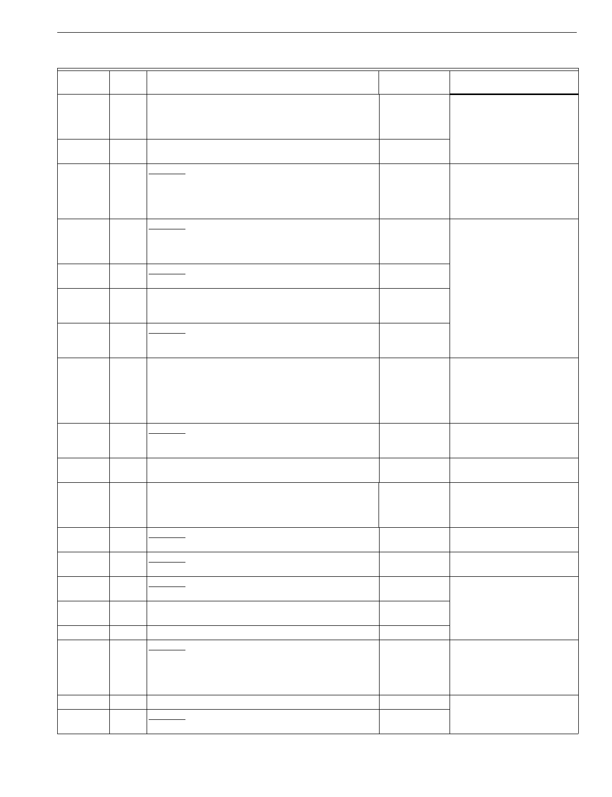
T874 MULTISTAGE THERMOSTATS AND Q674 SUBBASES
69 60-2485—8
R1889 120 Hone
y
well lo
g
o; desi
g
ned to replace Y594R1151
(
York
part no. 2TH11702324
)
, Y594R1193
(
York part no.
6TH11702224
)
, and York part no. 2TH11704024; used
with Q674L1736 and C815A1054; used in Y594R1672.
Y594R1672a
R1897 230 Hone
y
well lo
g
o; Premier White® color; used with
Q674L1751; used in Y594R1680. Y594R1680a
R1905 120 Obsolete. Hone
y
well lo
g
o; Premier White® color;
desi
g
ned to replace Y594R1151
(
York part no.
2TH11702324
)
, Y594R1193
(
York part no.
6TH11702224
)
, and York part no. 2TH11704024; used
with Q674L1777 and C815A1054; used in Y594R1698.
Y594R1672aReplacement is bei
g
e.
R1913 120 Obsolete. Hone
y
well lo
g
o; Premier White® color;
desi
g
ned to replace Y594R1011
(
York part no.
2TH11702224
)
; used with Q674L1777; used in
Y594R1706.
Y594R1664aReplacement is bei
g
e.
R1921 115 Obsolete. Econar lo
g
o; used with Q674L1207; used in
Y594R1722. Y594R1243a
R1939 197 American Standard lo
g
o
(
Trane
)
; part no.
ASYSTAT651A; includes outdoor reset; used with
Q7674L1801; used in Y594R1748.
Y594R1763a
R1947 168 Obsolete. Inter-Cit
y
Products lo
g
o; part no.
HQ1149406HW; used with Q674L1819; used in
Y594R1755.
Y594R1425a
R1954 197 Hone
y
well lo
g
o; TRADELINE model; includes outdoor
reset; used with Q674L1827; used in Y594R1763. Y594R1763aDirect replacement for
Y594R1748
(
T874R1939/
Q674L1801
)
American
Standard lo
g
o
(
ASYSTAT
651A
)
and Y594R1136
(
T874R1053/Q674L1140
)
.
R1962 115 Obsolete. Consolidated Industries lo
g
o; part no.
9036100; Premier White® color; used with Q674L1843;
used in Y594R1771.
Y594R1680aIncludes CHECK LED.
R1970 120 York lo
g
o; Canada; Premier White® color; °C scaleplate;
used in Y594R1789; used with C815A1039. Y594R1672aReplacement has °F
scaleplate.
R1988 125 Hone
y
well lo
g
o; TRADELINE model; used with
Q674L1868; used in Y594R1797. Y594R1797 Direct replacement for
Y594R1235
(
T874R1368/
Q674L1421
)
Evcon/Coleman
part no. 3600-368.
R2002 245 Obsolete. Amana Air Conditionin
g
lo
g
o; part no.
10574102; used in Y594R1805. Y594R1797 Wirin
g
differences
(
old=new
)
:
C/X=X.
R2010 245 Obsolete. Amana Air Conditionin
g
lo
g
o; part no.
10574104. Y594R1797 Wirin
g
differences
(
old=new
)
:
C/X=X, W3=W2.
R2028 209 Obsolete. York lo
g
o; part no. 2TH11703424A; used with
Q674L1918 in Y594R1821. Y594R1797
R2036 134 Ruud lo
g
o; °C scaleplate; used with Q674L1504. See OEM for
replacement.
T874S 2-sta
g
e heat, 3-sta
g
e cool.
S1001 223 Obsolete. Carrier S
y
ner
gy
2000 Heat Pump S
y
stem
Control lo
g
o; used with Q674F1501. T8611M2025
(
pro
g
rammable
)
or see OEM for
direct
replacement.
Includes ni
g
ht setback.
T874V 1-sta
g
e cool.
V1008 69 Obsolete. No lo
g
o; Carrier part no. HH07AT177; used
with Q674R1003. T874A1036
Table 8. T874 Cross Reference.
Model
Number Fig.
No. Description Trade Model
Replacement Remarks
aBoth the thermostat and subbase must be replaced.
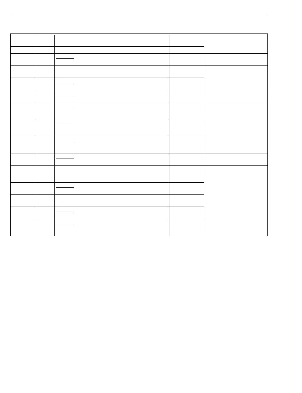
T874 MULTISTAGE THERMOSTATS AND Q674 SUBBASES
60-2485—870
T874W 3-sta
g
e heat, 2-sta
g
e cool, manual chan
g
eover.
W1007 118 Obsolete. Hone
y
well lo
g
o; Westin
g
house special; used
with Q674L1256. T8611M2025
(
pro
g
rammable
)
Includes ni
g
ht setback.
W1015 54 Hone
y
well lo
g
o; used with Q674B1216 and C815A1005;
used in Y594W1014. T874W1015
W1023 233 Obsolete. Lennox Advanced Heat Pump S
y
stem lo
g
o;
used with Q674L1280 and W89. T874W1015
W1031 140 Obsolete. No lo
g
o; Rheem part no. 41-20797-20; used
with Q674L1546 and C815A1005; used in Y594W1022. T8611M2025
(
pro
g
rammable
)
Includes ni
g
ht setback.
W1049 100 Obsolete. McQua
y
lo
g
o; part no. 61202501; 12°F
intersta
g
e differential between H2 and H3 for ni
g
ht
setback; used with Q674C1363.
T8611M2025
(
pro
g
rammable
)
Includes ni
g
ht setback.
W1056 220 Obsolete. McQua
y
/Sn
y
der General lo
g
o; part no.
1202501; 12°F differential between H2 and H3 for ni
g
ht
setback; used with Q674C1363
(
61202502
)
.
See OEM for
replacement.
W1064 220 Obsolete. AAF/Sn
y
der General lo
g
o; part no.
066804408; 12°F differential between H2 and H3 for
ni
g
ht setback; used with Q674C1363
(
66804408
)
.
See OEM for
replacement.
W1072 140 Obsolete. Hone
y
well lo
g
o
(
Inter-Cit
y
Products
)
; used in
Y594W1030. T8611M2025
(
pro
g
rammable
)
Includes ni
g
ht setback.
W1080 220 McQua
y
lo
g
o; part no. 073318901; Premier White®
color; 12°F differential between H2 and H3 for ni
g
ht
setback.
None
W1106 247 Obsolete. Addison lo
g
o; part no. 843-277; °F/°C
scaleplate; used with Q674L1934 in Y594W1055. T8611M2025
T874Y Heat pump model; 2-sta
g
e heat, 2-sta
g
e cool, heat or
cool auto chan
g
eover.
Y1005 210 Obsolete. Mammoth Water Source Heat Pump lo
g
o;
used with Q674E1353; used in Y594Y1004. See OEM for
replacement.
Y1013 248 Obsolete. WaterFurnace lo
g
o; part no. TA21H03;
Premier White® color; °F/°C scaleplate; used with
Q674F1675
(
32003081
)
.
See OEM for
replacement.
Table 8. T874 Cross Reference.
Model
Number Fig.
No. Description Trade Model
Replacement Remarks
aBoth the thermostat and subbase must be replaced.
T874 MULTISTAGE THERMOSTATS AND Q674 SUBBASES
71 60-2485—8
Table 9. Q674 Subbase Cross Reference.
Model
Number Fig.
No. Description Q674 Trade
Replacement Remarks
Q674A S
y
stem: HEAT-AUTO-COOL; Fan: AUTO-ON
A1001 71 Standard OEM. Q674A1019
A1019 71 TRADELINE® model; used with T874A-D. Q674A1019
A1035 71 Obsolete. Trane part no. BAS-0435; used with T874A-D. Q674A1019
A1043 71 Hone
y
well lo
g
o; TRADELINE model; Q674A1019
A1050 71 Obsolete. Standard OEM. Q674A1043
Q674B S
y
stem: HEAT-OFF-COOL; Fan: AUTO-ON
B1000 45 Standard OEM; used with T874C1570, C1695, C1703,
D1843; used in Y594C1363. Q674B1034
B1018 44 Standard OEM; used with T874B1035, D1082; used in
Y594B1026, D1016. Q674B1018
B1026 45 Obsolete. S
y
stem: HEAT-OFF-RESET-COOL. Q674B1034
B1034 45 TRADELINE Q674B1034
B1042 47 Obsolete. Used with T874R1004, R1509; used in
Y594R1029, R1334. Y594R1243aWirin
g
differences
(
old=new
)
:
W1=W2.
B1059 45 Obsolete. Factor
y
installed RC-RH
j
umper; used with
T874C1059; used in Y594C1256. Q674B1034 Field wire RC-RH.
B1075 46 Auto fan in heatin
g
and coolin
g
mode; used with
T874B1035, C1000, D1082; used in Y594D1040. Q674B1075
B1083 51 Obsolete. Carrier part no. HH93AZ178; factor
y
installed RC-RH
j
umper. Q674B1075aOne s
y
stem transformer onl
y
.
B1091 45 Obsolete. Carrier part no. HH93AZ184; factor
y
installed RC-RH
j
umper. Q674B1034
B1109 47 Obsolete. Addison heat pump; used with T874R1012. Y594R1243aWirin
g
differences
(
old=new
)
:
W1=W2.
B1117 44 Obsolete. Carrier part no. HH93AZ180; factor
y
installed RC-RH
j
umper. Q674B1018a
B1125 53 Obsolete. York part no. 2TB04700324A; used with
T874D1041. Q674B1075aJumper RC-RH; replacement
has no LOCKOUT LED.
B1133 48 Obsolete. Includes FILTER LED; used with
T874D1082; used in Y594D1156. Q674B1018
B1141 51 Trane part no. BAY28X185; automatic fan operation in
heat and cool mode. Q674B1075 Set T874 H1 anticipator for
combined load of heat rela
y
and fan rela
y
.
B1158 50 Obsolete. Used with T874G1071. T874C1018/
Q674B1018a
W1-Y1 and RH-RC
j
umpers
re
q
uired.
B1166 249 Carrier part no. HH93AZ179; factor
y
installed RC-RH
j
umper; LOCKOUT LED; used with T874C1075
(
HH07AT170
)
.
Y594C1421 or
Q674B1075a
Replacement onl
y
re
q
uires
one transformer and has no
LOCKOUT LED.
B1190 52 Obsolete. Wards special; factor
y
installed RH-RC and
F-W3
j
umpers; used with T874C1372. Gas Furnace:
Q674B1034
Electric Furnace:
Q674B1075
B1208 187 Obsolete. Used with T874C1422. None
B1216 54 Used with T874W1015 and C815A1005; used in
Y594W1014. Q674B1216
B1224 49 Obsolete. Lennox part no. 25F7301; four LEDs; used
with T874C1430. Q674B1034 Replacement has no LEDs.
aBoth the thermostat and subbase must be replaced.
T874 MULTISTAGE THERMOSTATS AND Q674 SUBBASES
60-2485—872
B1240 234 Obsolete. Northrup heat pump; AUX HEAT LED; used
with T874G1139. Y594G1252aWirin
g
differences
(
old=new
)
:
Y1=Y2, W1=W2; EM HT
s
y
stem switch position is not
operational.
B1257 56 Obsolete. LSI-Mammoth; RESET LED; automatic fan
operation in heat and cool modes; used with
T874C1471; used in Y594C1314.
Q674B1075 Replacement has no LED.
B1273 57 Obsolete. McQua
y
part no. 860-442727B-00; S
y
stem:
OVERRIDE-HEAT-OFF-COOL; used with T874P1006. T874A1036/
Q674B1075a
Wirin
g
differences
(
old=new
)
:
Y=Y1, L=R, W=O;
j
umper Y1-
W1; no ni
g
ht setback.
T8600D2028
(
pro
g
rammable
)
Wirin
g
differences
(
old=new
)
:
L=R, W=O; W-Y
j
umper
re
q
uired; ni
g
ht setback.
B1281 191 Obsolete. Carrier no. 42QH400103; S
y
stem: HEAT-
OFF-COOL; Fan: LOW-HI-CONT; international
s
y
mbols on switches; used with T874R1319.
See OEM for
replacement.
B1299 46 Obsolete. Heil Quaker part no. HQ521714HW. Q674B1075
B1307 62 Obsolete. Includes two LEDs; used with T874F1122. T874F1015/
Q674D1040a
Replacement has no LEDs.
B1315 68 Obsolete. Friedrich part no. AQ5215; OVERRIDE and
SERVICE LEDs; used with T874P1022, P1030. T8600D2028
(
pro
g
rammable
)
Wirin
g
differences
(
old=new
)
:
L=R, W=O; W-Y
j
umper
re
q
uired; set dual fuel switch
to electric heat; ni
g
ht setback.
B1331 65 Obsolete. Includes two LEDs; used with T874A1002. Q674B1034 Replacement has no LEDs.
B1349 67 Obsolete. Goettl part no. 372072; used with
T874R1541. Y594R1300a
B1356 138 Obsolete. Carrier part no. HH93AZ192; used with
T874L1018
(
HH07AT178
)
.See OEM for
replacement.
B1372 44 Obsolete. Trane part no. BAS-0427; used with T874A-D. Q674B1018
B1380 46 Obsolete. Trane part no. BAS-0426; used with T874A-D. Q674B1075
B1398 48 Obsolete. Trane part no. BAS-0431; FILTER LED;
used with T874A-D. Q674B1034 Replacement has no LEDs.
B1406 172 Obsolete. Carrier part no. HH93AZ200; FAULT and
CHECK FILTER LEDs; used with T874H1070
(
HH07AT166
)
, T874H1088
(
HH07AT167
)
or
T874H1153
(
HH07AT167
)
; used in Y594H1046.
T874A1150/
Q674B1075a
Wirin
g
differences
(
old=new
)
:
Y=Y1;
j
umper W1-Y1;
replacement has no LEDs.
B1414 51 American Standard
(
Trane
)
part no. ASYSTAT1617. Q674B1075
B1448 215 Obsolete. Carrier part no. HH93A2202; Fan: Lo-Med-
Hi
g
h-On; used with T874L1059. See OEM for
replacement.
B1455 214 Obsolete. Carrier part no. HH93AZ208; Fan: Lo-Med-
Hi
g
h-On; used with T874A1424
(
HH07AT194
)
.See OEM for
replacement.
B1463 45 Trol-A-Temp; used with T874D1801. None See Trol-A-Temp.
B1471 45 Trol-A-Temp; used with T874D1827. None See Trol-A-Temp.
B1513 53 Obsolete. TRADELINE; exact replacement for
Q674B1125
(
York part no. 2TB04700324
)
.Q674B1075 Jumper RC-RH; replacement
has no LOCKOUT LED.
B1521 53 Obsolete. Carrier Canada part no. HH93AZ179-W;
g
ra
y
color; includes LOCKOUT LED and removable
j
umpers between RC and RH terminals.
Q674B1075 Jumper RC-RH; replacement
has no LOCKOUT LED; bei
g
e
color.
B1539 45 Obsolete. Carrier part no. HH93AZ139; used with
T874D2049; used in Y594D1370. Q674B1034
B1547 237 Obsolete. TRADELINE;
g
ra
y
color; used with
T874C1810; used in Y594C1389. Y594C1389
Table 9. Q674 Subbase Cross Reference.
Model
Number Fig.
No. Description Q674 Trade
Replacement Remarks
aBoth the thermostat and subbase must be replaced.
T874 MULTISTAGE THERMOSTATS AND Q674 SUBBASES
73 60-2485—8
B1554 82 Obsolete. TRADELINE; includes LOCKOUT LED and
removable
j
umpers between RC and RH terminals;
used with T874C1877; used in Y594C1421.
Y594D1347 Jumper RH-RC; s
y
stem
switch: Off-HEAT-AUTO-
COOL.
B1562 45 Obsolete. Amana lo
g
o; part no. P1217701F;
removable
j
umpers between RC and RH terminals. Q674B1034
B1570 45 Obsolete. Armstron
g
lo
g
o; part no. 03299A18. Q674B1034 Replacement is bei
g
e.
B1588 45 Obsolete. Standard OEM. Q674B1034 Replacement is bei
g
e.
Q674C S
y
stem: OFF-AUTO; Fan: AUTO-ON
C1009 72 Standard OEM; used with T874D1082; used in
Y594D1024. Q674C1058
C1017 Obsolete. Includes factor
y
-installed RC-RH
j
umper;
used with T874A,F,Q. Q674C1058
C1033 72 Trane part no. BAY28X187. Q674C1058
C1041 74 Obsolete. Command Aire heat pump; used with
T874H1005, H1054. Y594H1012aWirin
g
differences
(
old=new
)
:
Y1=O, Y2=Y; W-Y
j
umper
re
q
uired.
C1058 72 TRADELINE Q674C1058
C1066 73 Obsolete. Command Aire heat pump; used with
T874G1352. Y594H1012aWirin
g
differences
(
old=new
)
:
Y1=O, Y2=Y, L=R, R=none; R-
L
j
umper re
q
uired; no ni
g
ht
setback.
T8600D2028
(
pro
g
rammable
)
Wirin
g
differences
(
old=new
)
:
Y1=O, Y2=Y, L=R; W-Y
j
umper re
q
uired; ni
g
ht
setback.
C1074 81 Obsolete. Used with T874C1018. Q674C1058 Jumper W2-Y1 and RH-RC.
C1090 77 Obsolete. LSI-Mammoth heat pump; used with
T874K1001. Y594R1419aWirin
g
differences
(
old=new
)
:
RH-RC=R, W1=B, W3=W2,
W2=W1; remove Y1-W1
j
umper.
C1108 143 Obsolete. Northrup special; AUX HEAT LED; used with
T874G1139. Y594R1243aWirin
g
differences
(
old=new
)
:
Y1=Y, W1=W2, C=X.
C1116 76 Obsolete. McQua
y
part no. 02005959; two LEDs; used
with T874D1116. Q674C1058 Replacement has no LEDs.
C1124 79 Obsolete. LSI-Mammoth heat pump; RESET LED;
used with T874G-H; used in Y594G-H. Y594G1294
T8600D2028
C1132 75 Obsolete. McQua
y
part no. 03005049; sprin
g
return
momentar
y
s
y
stem switch position; used with
T874A1283.
See OEM for
replacement.
C1140 78 Obsolete. McQua
y
no. 860-442728B-00; S
y
stem:
OVERRIDE-AUTO-OFF; used with T874P1006. T8600D2028
(
pro
g
rammable
)
Wirin
g
differences
(
old=new
)
:
L=R, W=O; W-Y
j
umper
re
q
uired; ni
g
ht setback.
C1157 72 Obsolete. York part no. 2TB04700124A. Q674C1058
C1165 192 Obsolete. McQua
y
part no. 03005050; sprin
g
return
momentar
y
s
y
stem switch position. See OEM for
replacement.
C1173 96 Obsolete. American Air Filter part no. 4ELN-8787;
used with T874C1133. Q674C1058 Replacement has no LEDs.
C1181 76 Obsolete. California heat pump; used with T874C1000. Q674C1058
C1199 163 Obsolete. American Air Filter part no. 4ELN-8788; two
LEDs; sprin
g
return momentar
y
s
y
stem switch position;
used with T874G1485, G1535.
T8600D2028 No momentar
y
reset switch.
Table 9. Q674 Subbase Cross Reference.
Model
Number Fig.
No. Description Q674 Trade
Replacement Remarks
aBoth the thermostat and subbase must be replaced.
T874 MULTISTAGE THERMOSTATS AND Q674 SUBBASES
60-2485—874
C1207 78 Obsolete. Friedrich; S
y
stem: OVERRIDE-AUTO-OFF;
used with T874P1014. T8600D2028
(
pro
g
rammable
)
Wirin
g
differences
(
old=new
)
:
L=R, W=O; W-Y
j
umper
re
q
uired; ni
g
ht setback.
C1215 97 Obsolete. Friedrich part no. AQ5315; S
y
stem:
OVERRIDE-AUTO-OFF; OVERRIDE and SERVICE
LEDs; used with T874P1022, P1030.
T8600D2028
(
pro
g
rammable
)
Wirin
g
differences
(
old=new
)
:
L=R, W=O; W-Y
j
umper
re
q
uired; ni
g
ht setback.
C1223 73 Obsolete. Friedrich part no. AQ5323; used on s
y
stems
re
q
uirin
g
ni
g
ht setback contacts; used with
T874G1584.
Y594H1012aWirin
g
differences
(
old=new
)
:
Y1=O, Y2=Y, L=R, R=none; R-
L
j
umper re
q
uired; no ni
g
ht
setback.
T8600D2028
(
pro
g
rammable
)
Wirin
g
differences
(
old=new
)
:
L=R, W=O; W-Y
j
umper
re
q
uired; ni
g
ht setback.
C1249 164 Includes MALFUNCTION LED; used with T874H1062;
used in Y594H1012. Y594H1012a
C1256 73 Obsolete. Used with T874G1618. Y594H1012aWirin
g
differences
(
old=new
)
:
Y1=O, Y2=Y, L=R, R=none; R-
L
j
umper re
q
uired; no ni
g
ht
setback.
T8600D2028
(
pro
g
rammable
)
Wirin
g
differences
(
old=new
)
:
L=R, W=O; W-Y
j
umper
re
q
uired; ni
g
ht setback.
C1264 165 Obsolete. Carrier part no. HH93AZ193; used with
T874L1018
(
HH07AT178
)
.See OEM for
replacement.
C1280 181,
203 Obsolete. McQua
y
heat pump; part no. 60687401;
COMP FAULT LED; used with T874K1019, L1034. T8600D2028 See thermostat description for
replacement information.
C1298 76,
225 Obsolete. McQua
y
part no. 60684801; SERVICE LED;
used with T874A1523, A1549, D1918. See OEM for
replacement.
C1306 75 Obsolete. McQua
y
part no. 60685001; SERVICE LED;
sprin
g
return momentar
y
s
y
stem switch position; used
with T874A1325.
See OEM for
replacement.
C1314 72 Obsolete. Trane part no. BAS-0429; used with T874A-F. Q674C1058
C1322 173 Obsolete. Carrier part no. HH93AZ199; FAULT and CK
FILTER LEDs; used with T874H1070
(
HH07AT166
)
,
T874H1088
(
HH07AT167
)
or T874H1153
(
HH07AT167
)
; used in Y594H1053.
Y594H1012aWirin
g
differences
(
old=new
)
:
2=X.
C1330 177 Obsolete. LSI-Mammoth part no. 71115201; RESET
LED; used on s
y
stems with ni
g
ht setback contacts;
used with T874G1659, H1096; used in Y594G1427,
H1020.
Y594H1012aWirin
g
differences
(
old=new
)
:
R1=R; R2=L.
C1355 74 Friedrich part no. AQ355; SERVICE LED; used with
T874H1112. Y594H1012aWirin
g
differences
(
old=new
)
:
Y1=O, Y2=Y; L-R
j
umper
re
q
uired.
C1363 99 Obsolete. McQua
y
part no. 61202601; SERVICE LED;
auto fan in heat and cool mode; used with T874C. T874C1125/
Q674B1075a
Replacement has HEAT-OFF-
COOL.
219 Obsolete. Used with T874C. See OEM for
replacement.
220 Obsolete. Used with T874W. See OEM for
replacement.
100 Obsolete. Used with T874W. T8611M2025
(
pro
g
rammable
)
Includes ni
g
ht setback.
C1371 72 American Standard part no. ASYSTAT616. Q674C1058
Table 9. Q674 Subbase Cross Reference.
Model
Number Fig.
No. Description Q674 Trade
Replacement Remarks
aBoth the thermostat and subbase must be replaced.
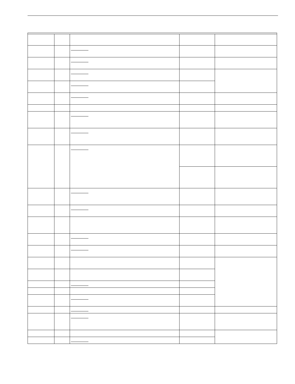
T874 MULTISTAGE THERMOSTATS AND Q674 SUBBASES
75 60-2485—8
C1389 205,
176 Obsolete. Command Aire part no. P1099-0021; two
LEDs; used with T874G-H. None See thermostat description for
replacement information.
C1397 205,
171 Obsolete. Command Aire part no. P1099-0023; used
with T874G-H. None See thermostat description for
replacement information.
C1413 213 Obsolete. Carrier part no. HH93AZ204; Fan: Lo-Med-
Hi
g
h-On; used with T874L1059. See OEM for
replacement.
C1439 217 Obsolete. Bard part no. 8404-016; used with
T874N1024. See OEM for
replacement.
C1454 163 Obsolete. Climate Master part no. AQ5354; two LEDs;
sprin
g
return momentar
y
s
y
stem switch position. Y594G1393aNo momentar
y
reset switch.
C1462 25 Climate Master Special. Q674C1058 Replacement has no LEDs.
C1470 221 Obsolete. Climate Master part no. RQ5370; used with
T874H1138. Y594H1012aWirin
g
differences
(
old=new
)
:
Y1=O, Y2=Y; replacement has
MALFUNCTION LED onl
y
.
C1496 74 Obsolete. Carrier part no. HH93AZ213; includes
SERVICE LED; used with T874H1161; used in
Y594H1038.
Y594H1012aWirin
g
differences
(
old=new
)
:
Y1=O, Y2=Y; L-R
j
umper
re
q
uired.
C1504 83 Obsolete. Carrier part no. HH93AZ214; used in Y594. Y594H1012aWirin
g
differences
(
old=new
)
:
Y1=O, Y2=Y, L=R, R=none; R-
L
j
umper re
q
uired; no ni
g
ht
setback.
T8600D2028
(
pro
g
rammable
)
Wirin
g
differences
(
old=new
)
:
Y1=O, Y2=Y, L=R; W-Y
j
umper re
q
uired; ni
g
ht
setback.
C1512 97 Obsolete. Carrier part no. HH93AZ216; S
y
stem:
Override-Auto-Off; includes two LEDs; used in Y594. T8600D2028
(
pro
g
rammable
)
Wirin
g
differences
(
old=new
)
:
L=R, W=O; W-Y
j
umper
re
q
uired; ni
g
ht setback.
C1520 72 Obsolete. Carrier part no. HH93AZ210; used with
T874D2049; used in Y594D1388. Q674C1058
C1538 163 Climate Master part no. AQ5354; S
y
stem: Off-Auto-
Override; includes two LEDs and momentar
y
sprin
g
position.
Y594G1393 No momentar
y
reset switch.
C1546 76,
225 Obsolete. McQua
y
part no. 060684802;
g
ra
y
color;
includes one LED. Q674C1058 Replacement has no LEDs;
bei
g
e color
C1553 181,
203 Obsolete. McQua
y
lo
g
o; part no. 073319901; includes
one LED. Q674C1058 Replacement is bei
g
e.
C1561 76 McQua
y
lo
g
o; part no. 073319701; includes one LED. See OEM for
replacement.
C1579 99,
100 McQua
y
lo
g
o; part no. 073320001; includes one LED. See OEM for
replacement.
C1595 72 Obsolete. Standard OEM. Q674C1058
Q674D S
y
stem: None; Fan: None
D1008 55, 66 Obsolete. Used with T874D1082, F1056; used in
Y594D1057. Q674D1040
D1016 55 Obsolete. Carrier part no. HH93AZ170; RC-RH
j
umper. Q674D1040 RC-RH
j
umper re
q
uired.
D1032 58 Obsolete. Bor
g
-Warner; used with T874G. T874D1165/
Q674D1040a
Wirin
g
differences
(
old=new
)
:
Y=Y2, O=Y1, W=W2;
j
umper
W1-Y2 re
q
uired.
D1040 55 TRADELINE Q674D1040
D1057 55, 66 Obsolete. York part no. 2TB04700424A. Q674D1040
Table 9. Q674 Subbase Cross Reference.
Model
Number Fig.
No. Description Q674 Trade
Replacement Remarks
aBoth the thermostat and subbase must be replaced.
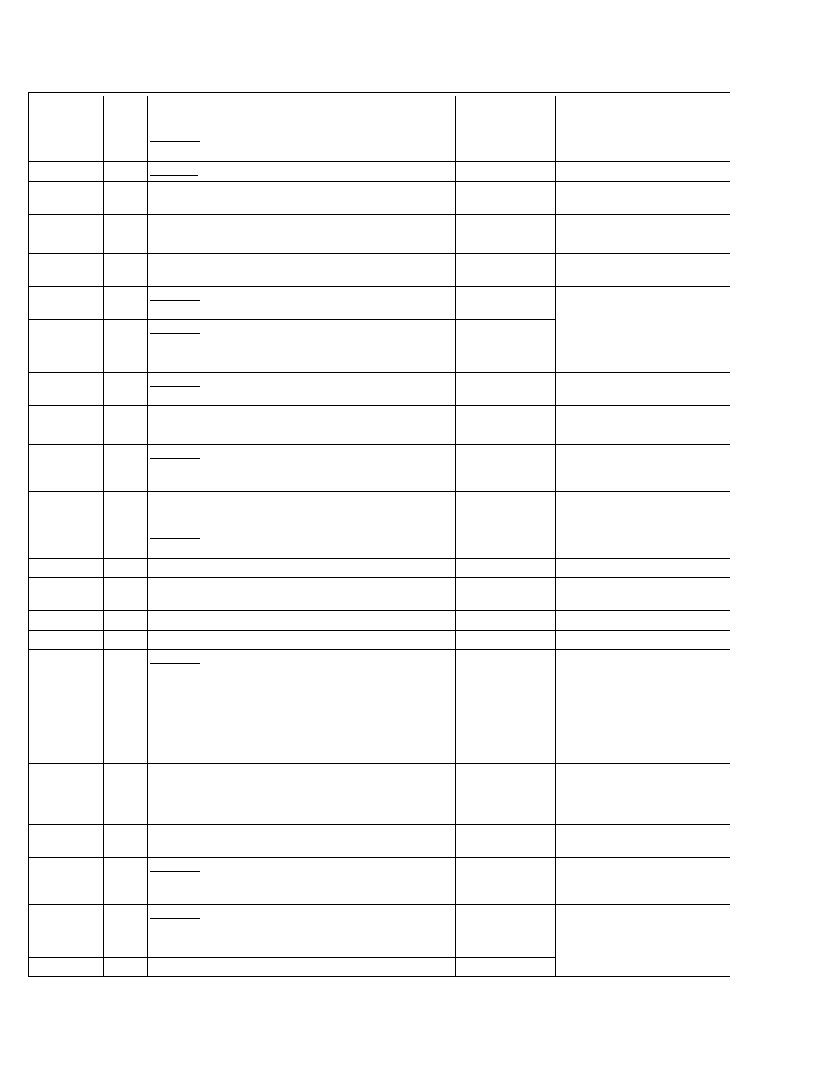
T874 MULTISTAGE THERMOSTATS AND Q674 SUBBASES
60-2485—876
D1065 63 Obsolete. Includes two LEDs; used with T874F1122. T874F1015/
Q674D1040a
Replacement has no LEDs.
D1099 55, 66 Obsolete. Trane part no. BAS-0430; used with T874A-F. Q674D1040
D1107 55, 66 Obsolete. Sn
y
der General part nos. 654958801/
1520503/ 4ELN30070. Q674F1040.
D1115 208 Trol-A-Temp; used with T874D1801. None See Trol-A-Temp.
D1123 208 Trol-A-Temp;
g
ra
y
color; used with T874D1827. None See Trol-A-Temp.
D1156 55 Obsolete. Gra
y
color; includes removable
j
umper
between RC and RH terminals. Q674D1040 Replacement is bei
g
e color.
D1164 66 Obsolete. Carrier part no. HH93AZ211; used in
Y594D1440. Q674D1040
D1172 208 Obsolete. Amana lo
g
o; part no. P121501F; removable
j
umpers between RC and RH terminals. Q674D1040
D1180 55 Obsolete. York lo
g
o; part no. 2TH04703224A. Q674D1040
D1198 55, 66 Obsolete. Standard OEM. T874D1165/
Q674D1040 Replacement is bei
g
e color.
Q674E S
y
stem: OFF-HEAT-AUTO-COOL; Fan: AUTO-ON
E1007 82 Used with T874D1504; used in Y594D1180. Q674E1049
E1015 84 Obsolete. Lennox heat pump; used with T874G1006,
G1154. Y594G1252aWirin
g
differences
(
old=new
)
:
R=O, M=Y, F=G, V=R, Y=W2;
E-W2
j
umper re
q
uired.
E1049 193 TRADELINE; used with T874D2031 and TG504A1025;
used in Y594D1354. Q674E1049
E1056 82 Obsolete. Amana part no. D68535-7; used with
T874C1059, C1331; used in Y594C1009. Q674E1049 RC-RH
j
umper re
q
uired.
E1064 83 Obsolete. RC-RH
j
umpered internall
y
; EM HEAT LED. Q674E1049
E1072 82 Carrier part no. HH93AZ176; RC-RH
j
umpered
internall
y
.Q674E1049 RC-RH
j
umper re
q
uired.
E1080 82 Trane part no. BAY28X184. Q674E1049
E1098 85 Obsolete. Used with T874A-D. Q674E1049 RC-RH
j
umper re
q
uired.
E1106 185 Obsolete. ITT Nesbitt. See OEM for
replacement.
E1114 87 Carrier part no. HH93AZ177; RC-RH
j
umper;
LOCKOUT LED to indicate compressor lockout; used
with HH07AT series thermostats.
Q674E1049 RC-RH
j
umper re
q
uired;
replacement has no LED.
E1122 83 Obsolete. S
q
uare D part no. 63600-002-10; CHECK
LED. Q674E1049 Replacement has no LED.
E1148 86 Obsolete. Lennox heat pump; used with T874G1014,
G1022. Y594G1252aWirin
g
differences
(
old=new
)
:
R=O, M=Y, F=G, Y=W2,
V-VR=R; must use sin
g
le
transformer.
E1155 88 Obsolete. Lennox part no. 91C7501; HIGH and LOW
LEDs; used with T874B1076, D1017. Q674E1049 Replacement has no LEDs.
E1197 89 Obsolete. McQua
y
part no. 02005961; two LEDs; used
with T874D1116. Q674E1049 Wirin
g
differences
(
old=new
)
:
D=O; replacement has no
LEDs.
E1205 80 Obsolete. Fedders special; SERVICE LED; used with
T874D1462. Q674E1049 Replacement has no LEDs.
E1213 82 York part no. 2TB04700224A. Q674E1403
E1221 82 Heil Quaker part no. HQ712003HW. Q674E1049
Table 9. Q674 Subbase Cross Reference.
Model
Number Fig.
No. Description Q674 Trade
Replacement Remarks
aBoth the thermostat and subbase must be replaced.
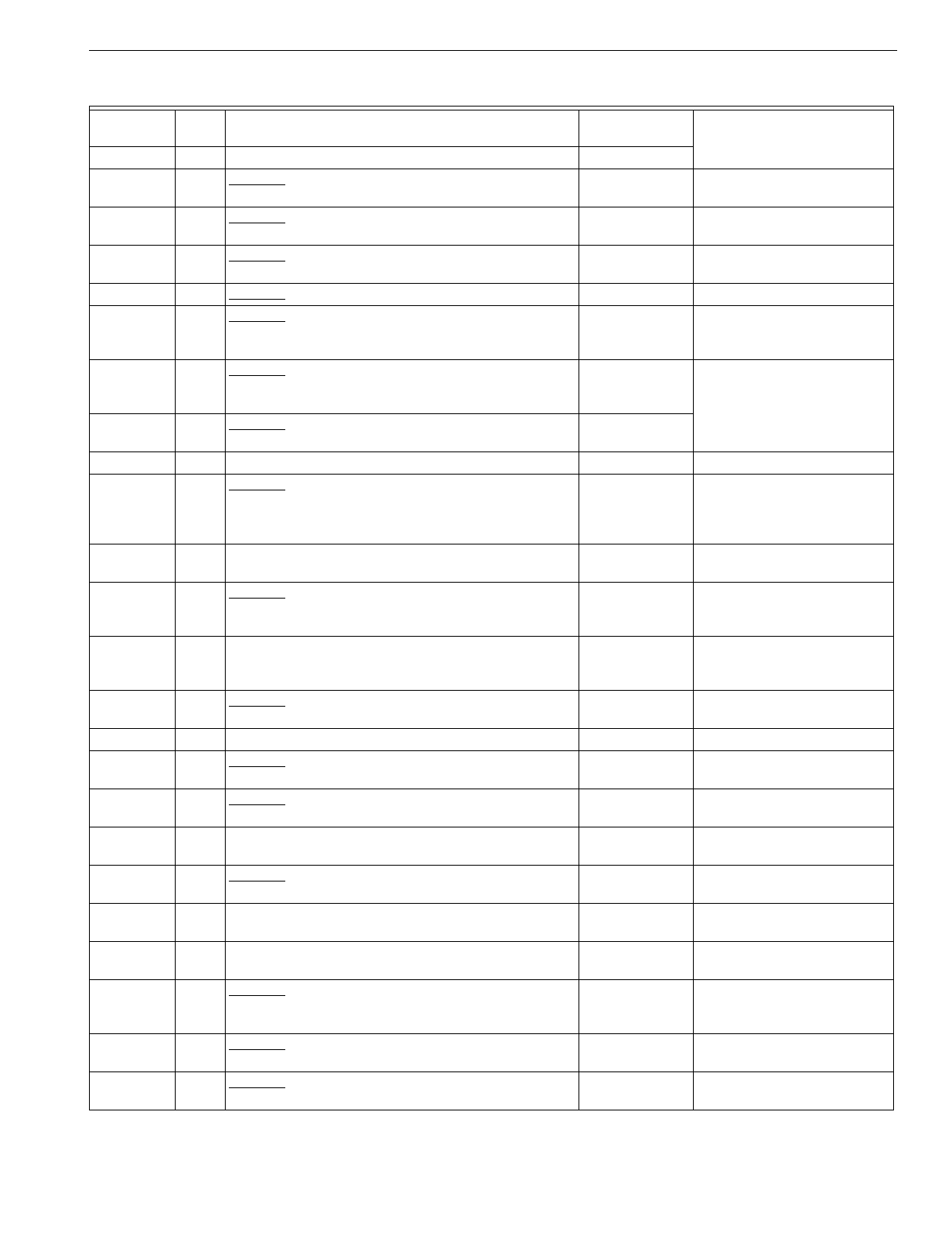
T874 MULTISTAGE THERMOSTATS AND Q674 SUBBASES
77 60-2485—8
E1262 82 Lennox part no. 13F1701. Q674E1049
E1270 198 Obsolete. Carrier part no. HH93AZ189; used with
T874L1000
(
HH07AT176
)
.Y594G1419aE-W2
j
umper re
q
uired.
E1304 82 Obsolete. BDP part no. P272-1887; used with
T874L1026. Y594G1419aE-W2
j
umper re
q
uired.
E1312 224 Obsolete. McQua
y
part no. 60684901; one LED; used
with T874A1523, A1549, D1686, D1918. Q674E1049 Replacement has no LEDs.
E1320 82 Obsolete. Trane part no. BAS-0434. Q674E1049
E1338 88 Obsolete. Goodman part no. CHTS36-60; HIGH and
LOW LEDs; used with T874B1100; used in
Y594B1042.
Q674E1049 Replacement has no LEDs.
E1346 82 Obsolete. Sn
y
der General part nos. 1505753/1506753/
654958B02; used with T874D1769; used in
Y594D1297.
Q674E1049
E1353 210 Obsolete. Mammoth; used with T874Y1005; used in
Y594Y1004. T8611M2025
E1379 212 Trol-A-Temp b
y
Hone
y
well; used with T874A1465. None See Trol-A-Temp.
E1395 222 Obsolete. Carrier part no. HH93AZ209; used with
T874B1134
(
HH07AT199
)
.T874B1019/
Q674E1049a
Wirin
g
differences
(
old=new
)
:
W1 =W; RC-RH
j
umper
re
q
uired; replacement has no
LEDs.
E1403 82 TRADELINE; desi
g
ned to replace York 2TH04701024;
used with T874D1942; used in Y594D1347. Y594D1347a
E1411 82 Obsolete. Carrier Canada part no. HH93AZ176-W;
g
ra
y
color; removable
j
umper between RC and RH
terminals.
Q674E1049 RC-RH
j
umper re
q
uired.
Replacement is bei
g
e color.
E1429 87 Carrier Canada part no. HH93AZ177-W;
g
ra
y
color;
includes LOCKOUT LED; removable
j
umper between
RC and RH terminals.
Q674E1049 RC-RH
j
umper re
q
uired.
Replacement has no LOCK-
OUT LED and is bei
g
e color.
E1445 82 Obsolete. Carrier part no. HH93AZ217-W;
g
ra
y
color;
removable
j
umper between RC and RH terminals. Q674E1049 RC-RH
j
umper re
q
uired.
Replacement is bei
g
e color.
E1460 224 McQua
y
lo
g
o; part no. 073319801; includes one LED.
E1478 82 Obsolete. Armstron
g
lo
g
o; part no. 03299A19. Q674E1049 RC-R
j
umper re
q
uired.
Replacement is bei
g
e color.
E1486 82 Obsolete. Standard OEM. Q674E1049 RC-R
j
umper re
q
uired.
Replacement is bei
g
e color.
Q674F S
y
stem: EM.HT.-HEAT-AUTO-COOL-OFF;
Fan: AUTO-ON
F1006 141 Obsolete. Includes EM HEAT LED; used with
T874C1331. Q674F1022 Jumper E-X2.
F1022 142 Includes LED and field selectable inserts; used with
T874C1059; used in Y594C1017, C1330. Q674F1022
F1030 146 Carrier part no. HH93AZ174; SUPL HEAT LED; used
with T874D1074
(
HH07AT172
)
.Q674F1022 Wirin
g
differences
(
old=new
)
:
C=X1, X=X2.
F1048 149 Obsolete. Includes EM HEAT LED and auxiliar
y
power
terminal Z. Q674F1022 Replacement does not include
Z terminal and onl
y
re
q
uires
one transformer.
F1063 146 Obsolete. Carrier part no. HH93AZ181; SUPL HEAT
LED; used with T874D1074
(
HH07AT172
)
.Q674F1022 Wirin
g
differences
(
old=new
)
:
C=X1, X=X2.
F1071 142 Obsolete. S
q
uare D part no. 63600-002-11; CHECK
LED. Q674F1022
Table 9. Q674 Subbase Cross Reference.
Model
Number Fig.
No. Description Q674 Trade
Replacement Remarks
aBoth the thermostat and subbase must be replaced.
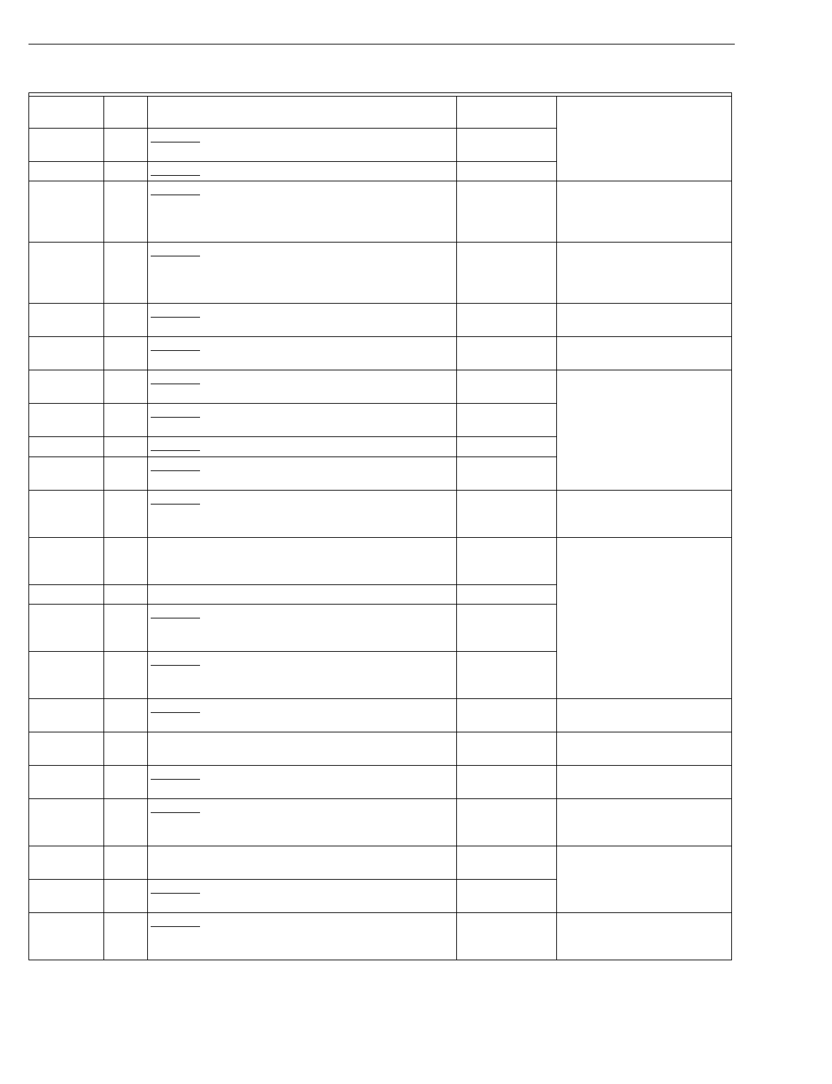
T874 MULTISTAGE THERMOSTATS AND Q674 SUBBASES
60-2485—878
F1089 152 Obsolete. Includes EM HEAT LED; X2-E and RC-RH
j
umpers. Q674F1022
F1097 142 Obsolete. Southwest special; W2-X2
j
umper. Q674F1022
F1105 145 Obsolete. Lennox heat pump; EM HEAT LED; used
with T874G1154. Y594G1252aWirin
g
differences
(
old=new
)
:
V=R, Y=W2, F=G, X2=X,
R=O, M=Y; L-E
j
umper
re
q
uired.
F1113 150 Obsolete. Lennox heat pump; part no. 24F6201; V-VR
j
umper; EM HEAT LED; chan
g
eover in coolin
g
; used
with T874G1014, G1022.
Y59461252aWirin
g
differences
(
old=new
)
:
R=O, M=Y, F=G, Y=WC,
V=VR=R; must use sin
g
le
transformer.
F1121 153 Obsolete. Westin
g
house heat pump; EM HEAT LED;
used with T874G1048. Y594G1252a
F1139 148 Obsolete. Tappan heat pump; EM HEAT LED; auto fan
in emer
g
enc
y
heat mode; used with T874G1147. Y594G1252aWirin
g
differences
(
old=new
)
:
C=X.
F1162 151 Obsolete. Crispaire heat pump; EM HEAT LED; used
with T874G. Y594G1393a
F1170 153 Obsolete. Heatwave
(
Southwest Mf
g
.
)
heat pump; EM
HT LED; used with T874G1105. Y594G1252a
F1188 153 Obsolete. Luxaire heat pump. Y594G1252a
F1196 178 Obsolete. Williamson; EM HEAT and SERVICE LEDs;
used with T874N1008; used in Y594N1007. Q674F1220
F1204 154 Obsolete. Special for Crispaire; EM HEAT and COMP
FAULT LEDs; used with T874G1089; used in
Y594G1153.
Y594G1393aWirin
g
differences
(
old=new
)
:
A=L.
F1212 155 Includes AUX HEAT and EM HEAT LEDs; used with
T874G1246, G1451, G1592, G1915; used in
Y594G1252.
Q674F1212 or
Y594G1252a
F1220 178 Used with T874N1016; used in Y594N. Q674F1220
F1238 155 Obsolete. Rheem part no. 41-20797-14; AUX HEAT
and EM HEAT LEDs; used with T874G1097, G1212,
G1220, G1238.
Y594G1252a
F1246 156 Obsolete. Westin
g
house heat pump; EM HEAT and
AUX HEAT LEDs; auto fan in emer
g
enc
y
heat mode;
chan
g
eover in coolin
g
mode.
Y594G1252a
F1253 157 Obsolete. Wesco/Addison heat pump; used with
T874G1261, G1279, G1287. Y594G1252aWirin
g
differences
(
old=new
)
:
Y1=O, C=X, W1=Y, X=L.
F1261 179 Includes two LEDs; used with T874N1024; used in
Y594N. Y594G1419aWirin
g
differences
(
old=new
)
:
L=X2, Y=Y1.
F1279 158 Obsolete. Westin
g
house heat pump; two LEDs; used
with T874G. Y594G1252aWirin
g
differences
(
old=new
)
:
L1=L.
F1295 147 Obsolete. Keeprite/Westin
g
house heat pump;
SERVICE, AUX HEAT and EM HEAT LEDs; used with
T874G1188.
Y594G1252aWirin
g
differences
(
old=new
)
:
S=L; replacement does not
include A or T terminals.
F1311 155 York heat pump; AUX HEAT and EM HEAT LEDs; used
with T874G1410. Y594G1252a
F1329 142 Obsolete. Heil Quaker part no. HQ712005HW; one
LED and field selectable inserts. Q674F1022
F1337 166 Obsolete. WeatherKin
g
heat pump; two LEDs and field
selectable inserts; used with T874D1009; used in
Y594D1222.
Q674F1022 Wirin
g
differences
(
old=new
)
:
R=RC-RH; replacement has
no LEDs.
Table 9. Q674 Subbase Cross Reference.
Model
Number Fig.
No. Description Q674 Trade
Replacement Remarks
aBoth the thermostat and subbase must be replaced.
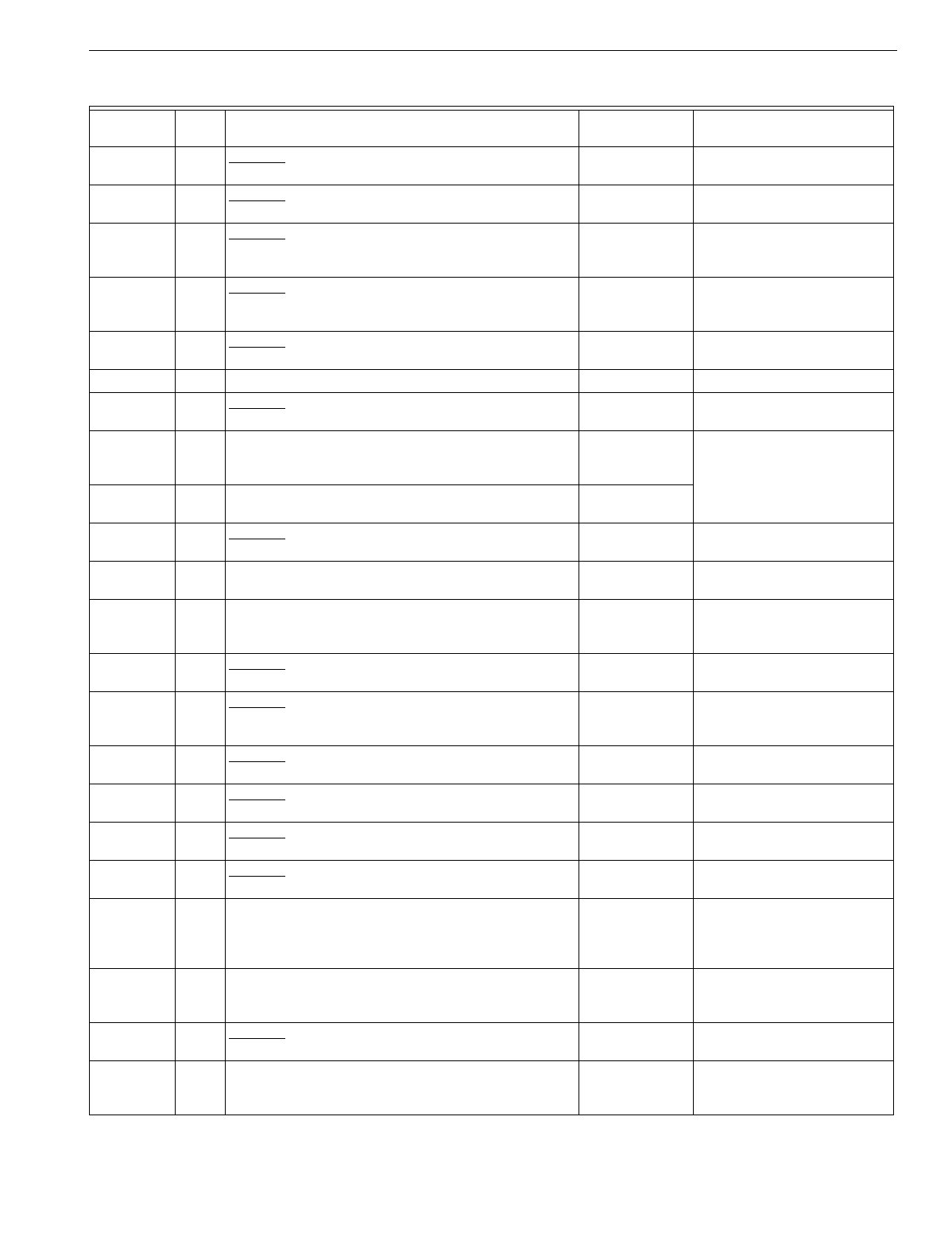
T874 MULTISTAGE THERMOSTATS AND Q674 SUBBASES
79 60-2485—8
F1345 194 Obsolete. Addison heat pump; EM HEAT and CHECK
LEDs; used with T874G; used in Y594G. Y594G1252aWirin
g
differences
(
old=new
)
:
Y1=O, C=X, W1=Y, X=L.
F1360 167 Obsolete. Rheem part no. 41-20797-17; AUX HEAT
and EM HEAT LEDs; used with T874G1493. Y594G1526a
F1378 195 Obsolete. Includes EM HEAT and AUX HEAT LEDs;
used with T874G1501. Y594G1252aWirin
g
differences
(
old=new
)
:
L1=L; chan
g
eover in coolin
g
onl
y
.
F1394 139 Obsolete. Nepco heat pump; HEAT PUMP and AUX
HEAT LEDs; S
y
stem: AUX HEAT-HEAT PUMP-2
STAGE HEAT-OFF-COOL; used with T874D1595.
T874D1165/
Q674B1018a
Replacement has HEAT-OFF-
COOL s
y
stem switchin
g
and
no LEDs.
F1402 169 Obsolete. Coleman heat pump; two LEDs; used with
T874G1576; used in Y594G1377. Y594G1633a
F1410 170 Used with T874G1246, G1915; used in Y594G1393. Y594G1393a
F1428 199 Obsolete. Used with T874G1600; used in Y594G1401. Y594G1419aWirin
g
differences
(
old=new
)
:
j
umper W1-Y1.
F1436 167 Includes AUX HEAT and EM HEAT LEDs; chan
g
eover
in heatin
g
mode; used with T874G1626; used in
Y594G1526.
None
F1444 227 Includes AUX HEAT, EM HEAT and CHECK LEDs;
used with T874G1642; used in Y594G1419. Y594G1419a
F1451 204 Obsolete. York part no. 2TB047700524A; one LED and
field selectable inserts. Q674F1012 Wirin
g
differences
(
old=new
)
:
X2=X; X1=B.
F1477 227 TRADELINE;
g
ra
y
color; used with T874G1741,
G1824; used in Y594G1476, G1534. Y594G1476a
F1485 211 Trol-A-Temp b
y
Hone
y
well; chan
g
eover is provided b
y
Trol-A-Temp zone panel; used with T874G1758; used
in Y594G1492.
None See Trol-A-Temp.
F1501 223 Obsolete. Carrier two-speed compressor heat pump;
used with T874S1001. T8611M2025
(
pro
g
rammable
)
Includes ni
g
ht setback.
F1519 231 Obsolete. Nord
y
ne; used with T874G1832, G1840;
used in Y594G1542, G1559. Y594G1252aReplacement has auto
chan
g
eover in coolin
g
mode
onl
y
.
F1535 229 Obsolete. Lennox heat pump;
g
ra
y
color; used with
T874G1857; used in Y594G1583. Y594G1161aWirin
g
differences
(
old=new
)
:
E=X2, C=B, L=F.
F1543 204 Obsolete. TRADELINE Q674F1022 Wirin
g
differences
(
old=new
)
:
X2=X, X1=B.
F1550 243 Obsolete. Amana part no. 10573901; includes two
LEDs; used with T874G1899; used in Y594G1591. Y594G1633
F1568 155 Obsolete. Gra
y
color; includes two LEDs; used with
onl
y
T874G1931. Y594G1476 Y1-W1
j
umper re
q
uired.
F1584 169 TRADELINE; includes two LEDs; used with
T874G1972; used in Y594G1633. Direct replacement
for Coleman/Evcon Y594G1377
(
T874G1576/
Q674D1402
)
; Coleman part no. 3600-373.
Y594G1633a
F1592 238 Heat Controller; Fan: AUTO-ON; S
y
stem: AUX HEAT-
HEAT PUMP- 2 STAGE HEAT-OFF-COOL; includes
two LEDs; used with T874C1844; used in Y594C1413.
Y594R1425 E-W2
j
umper re
q
uired; s
y
stem
switch: EM.HT.-HEAT-OFF-
COOL.
F1600 169 Obsolete. Amana part no. 10573903; includes two
LEDs; used with T874G1980; used in Y594G1641. Y594G1633 Wirin
g
differences
(
old=new
)
;
W3=W2.
F1634 139 Standard OEM; S
y
stem: AUX HEAT-HEAT PUMP-
2 STG HEAT-OFF-COOL; includes two LEDs; used
with T874D2155.
Y594G1716
Table 9. Q674 Subbase Cross Reference.
Model
Number Fig.
No. Description Q674 Trade
Replacement Remarks
aBoth the thermostat and subbase must be replaced.
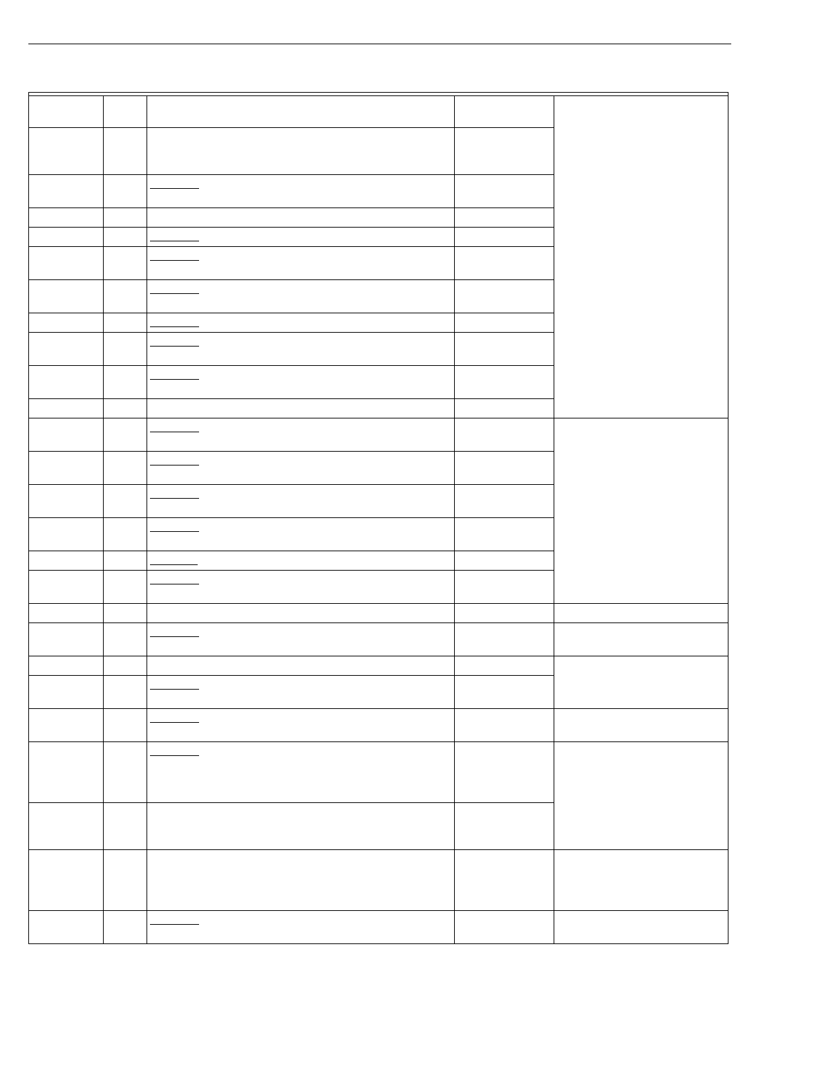
T874 MULTISTAGE THERMOSTATS AND Q674 SUBBASES
60-2485—880
F1667 155 WaterFurnace lo
g
o; part no. TA21H03; S
y
stem: OFF-
AUTO-HEAT-EM HT; includes two LEDs; used with
T874G2046.
Y594G1716
F1675 248 Obsolete. WaterFurnace lo
g
o; part no. TA21H03;
includes four LEDs. See OEM for
replacement.
Q674G S
y
stem: OFF-AUTO; Fan: None
G1005 184 Obsolete. Used in Y594F1063. Q674G1070
G1013 186 Obsolete. Climate Control; used with T874D1298. See OEM for
replacement.
G1021 91 Obsolete. Includes O and B terminals; used with
T874A-F,Q or T874D1082; used in Y594D1032. Q674G1070
G1047 92 Obsolete. Used with T874C1018, C1125. T8611
G1054 188 Obsolete. Sin
g
er part no. 0200-5963; used with
T874D1298. See OEM for
replacement.
G1062 232 Obsolete. Sin
g
er; used with T874D1298. See OEM for
replacement.
G1070 91 TRADELINE Q674G1070
G1088 92 Obsolete. LSI-Mammoth part no. 71120201; used with
T874C. See OEM for
replacement.
G1096 90 Obsolete. Climate Control part no. 02005958; used
with T874D1439, D1447. See OEM for
replacement.
G1104 94 Obsolete. McQua
y
part no. 0200-5963; two LEDs;
used with T874D1116. See OEM for
replacement.
G1120 202,
226 Obsolete. McQua
y
part no. 60684701; two SERVICE
LEDs; no fan switchin
g
; used with T874D1694, G1926. See OEM for
replacement.
G1138 91 Obsolete. Trane part no. BAS-0433; used with T874A-F. Q674G1070
G1153 184 Obsolete. Carrier part no. HH93AZ212; used in
Y594D1396. Q674G1070
G1161 184 Gra
y
color. Q674G1070 Replacement is bei
g
e color.
G1179 202 Obsolete. McQua
y
lo
g
o; part no. 073319601; includes
two LEDs. Q674G1161 Replacement has no LEDs.
Q674J S
y
stem: EM.HT.-AUTO-OFF; Fan: AUTO-ON
J1001 180 Obsolete. Sin
g
er heat pump part no. 02005964; EM
HEAT LED; chan
g
eover heat mode. See OEM for
replacement.
J1019 159 Obsolete. Westin
g
house heat pump; EM HT LED;
S
y
stem: EM.HT.-ON-OFF; used with T874G1048. Y594G1252aWirin
g
differences
(
old=new
)
:
W=W2.
J1027 160 Obsolete. York part no. 025-22291; EM HEAT LED;
auto fan in emer
g
enc
y
heat mode; chan
g
eover in cool
mode; used with T874G1170, G1196, G1428, G1345,
G1444; used in Y594G1013, G1138, G1229.
Y594G1567a
J1035 161 Carrier heat pump; part no. HH93AZ173; S
y
stem:
SUPL.HT.-ON-OFF; SUPL HEAT LED; used with
T874G1055
(
HH07AT171
)
.
Y594G1674a
J1043 162 TRADELINE heat pump model; desi
g
ned for use on
Trane heat pumps; AUX HT and EM HT LEDs; auto fan
in emer
g
enc
y
heat; chan
g
eover in coolin
g
mode; used
with T874G1204 and C815A1008; used in Y594G1161.
Q674J1043 or
Y594G1161a
Desi
g
ned for use on Trane
heat pumps.
J1050 183 Obsolete. Westin
g
house heat pump; EM HEAT and
AUX HEAT LEDs; used with T874G1071. Y594G1674a
Table 9. Q674 Subbase Cross Reference.
Model
Number Fig.
No. Description Q674 Trade
Replacement Remarks
aBoth the thermostat and subbase must be replaced.
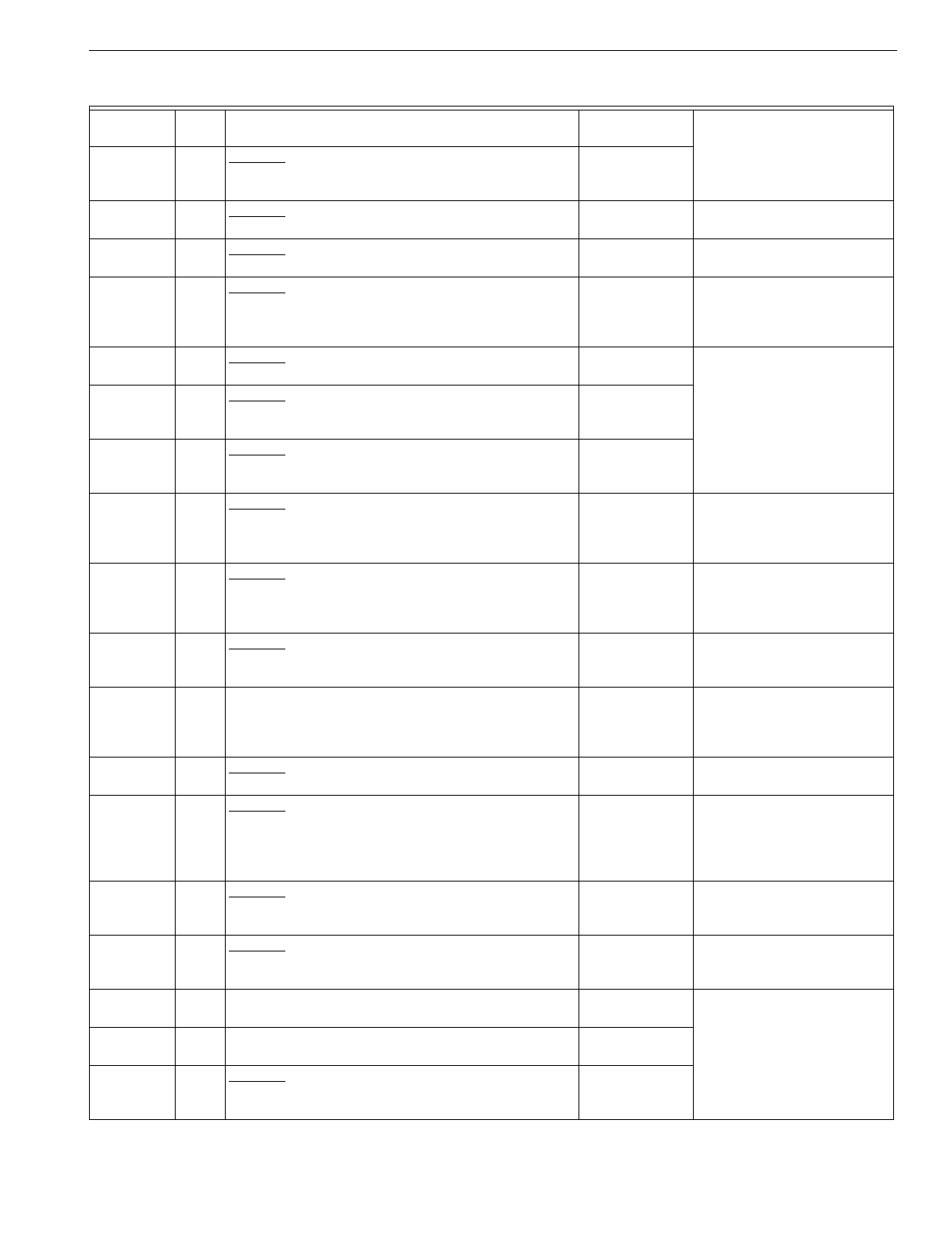
T874 MULTISTAGE THERMOSTATS AND Q674 SUBBASES
81 60-2485—8
J1068 144 Obsolete. Carrier heat pump; part no. HH93AZ183;
used with T874J1002
(
HH07AT175
)
or T874J1028
(
HH07AT165
)
.
Y594J1019
J1076 180 Obsolete. McQua
y
part no. 02005964; two LEDs; used
with T874A,D. Q674F1022 Replacement has no LEDs.
J1084 171 Obsolete. BDP heat pump; part no. 34427DP126,
P272-1879; EM HEAT LED; used with T874J1010. Y594J1019 Wirin
g
differences
(
old=new
)
:
W1=W2, F=L.
J1118 196 Obsolete. Carrier heat pump; part no. HH93AZ188;
SUPL HEAT LED; S
y
stem: SUPL.HT.-ON-OFF; used
with T874G1055
(
HH07AT171
)
.
Y594G1674 Wirin
g
differences
(
old=new
)
:
C=X;Y1=W1;
j
umper re
q
uired;
no auto fan in emer
g
enc
y
heat.
J1126 160 Obsolete. Luxaire no. 026-00068-000; EM HEAT LED;
used with T874G1568; used in Y594G1351. Y594G1567a
J1142 174 Obsolete. American Standard part no. WY28X0250;
AUX HEAT and EM HEAT LEDs; used with
T874G1675; used in Y594G1443.
Y594G1161a
J1159 206 Obsolete. Carrier heat pump; part no. HH93AZ196;
used with T874J1002
(
HH07AT175
)
or T874J1028
(
HH07AT165
)
.
Y594J1019
J1167 175 Obsolete. Carrier heat pump; MANUAL, AUTO, HEAT
PUMP and DEFROST LEDs; S
y
stem: SUPL HEAT-
ON-OFF; used with T874G1717; used in Y507J1201.
Y594G1252aWirin
g
differences
(
old=new
)
:
C=X, D=L; replacement has
AUX HEAT and EM HEAT
LEDs.
J1175 216 Obsolete. Sn
y
der General part nos. 1505756,
1506756; CHECK, AUX HEAT and SYSTEM LEDs;
used with T874G1774, G1782; used in Y594G1500,
G1518.
Y594G1252aWirin
g
differences
(
old=new
)
:
E=W2, W1=W3, X=E, C=X.
J1191 161 Obsolete. Carrier heat pump;
g
ra
y
color; used with
T874G1790. Y594G1252aWirin
g
differences
(
old=new
)
:
C=X; replacement has °F
scaleplate.
J1209 160 TRADELINE; desi
g
ned to replace Y594G1013
(
York
part no. 2TH11702424
)
, Y594G1229
(
York part no.
6TH11702424
)
and York part no. 2TH11704124; used
with T874G1865; used in Y594G1567.
Y594G1567a
J1217 171 Obsolete. Nord
y
ne part no. 9132250; used with
T874J1036, J1044. Y594J1019 Wirin
g
differences
(
old=new
)
:
F=L.
J1225 160 Obsolete. TRADELINE;
g
ra
y
color; desi
g
ned to replace
Y594G1013
(
York part no. 2TH11702424
)
, Y594G1229
(
York part no. 6TH11702424
)
and York part no.
2TH11704124; used with T874G1873; used in
Y594G1575.
Y594G1567aReplacement is bei
g
e.
J1241 144 Obsolete. Carrier Canada part no. HH93AZ183-W;
g
ra
y
color; S
y
stem: SUPL HT-ON-OFF; includes one
LED.
See OEM for
replacement.
J1258 161 Obsolete. Carrier Canada part no. HH93AZ173-W;
g
ra
y
color; S
y
stem: SUPL HT-ON-OFF; includes one
LED.
Y594G1674aReplacement is bei
g
e color.
J1266 160 York Canada;
g
ra
y
color; includes EM HT LED; used in
Y594G1625. Y594G1567a
J1274 161 TRADELINE; S
y
stem: SUPL HT-ON-OFF; includes
one LED; used with T874G2004; used in Y594G1674. Y594G1674
J1282 244 Obsolete. TRADELINE; S
y
stem: SUPL HT-ON-OFF;
includes SUPL HT LED; used with T874J1069; used in
Y594J1019.
(
Recontrol
)
T8511G1021
Table 9. Q674 Subbase Cross Reference.
Model
Number Fig.
No. Description Q674 Trade
Replacement Remarks
aBoth the thermostat and subbase must be replaced.
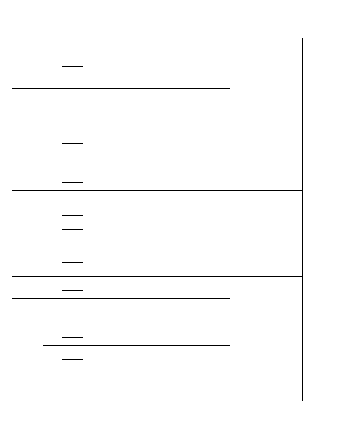
T874 MULTISTAGE THERMOSTATS AND Q674 SUBBASES
60-2485—882
Q674K S
y
stem: OFF-HEAT-AUTO-COOL; Fan: None
K1000 93 Obsolete. Carrier part no. HH93AZ172; RC-RH
j
umper. Q674E1049 Fan switch is not operational.
K1018 95 Obsolete. Oneida Heater part no. 3040284-02;
S
y
stem: OFF-WOOD-WOOD/OIL-OIL; used with
T874F1106.
Q674K1026
K1026 95 S
y
stem: OFF-WOOD-WOOD/ OIL-OIL; used with
T874F1155. Q674K1026
K1034 93 Obsolete. Sn
y
der General part no. 4ELN-7920. Q674E1049 Fan switch is not operational.
K1042 93 Obsolete. Carrier part no. HH93AZ172-W;
g
ra
y
color;
includes removable
j
umper between RC and RH
terminals.
Q674E1049 Fan switch is not operational.
Q674L S
y
stem: EM.HT.-HEAT-OFF-COOL; Fan: ON-AUTO
L1017 101 Obsolete. York heat pump; EM HEAT LED; coolin
g
mode chan
g
eover; compressor lockout; auto fan in
EM.HT; used with T874R1046.
Y594R1243aWirin
g
differences
(
old=new
)
:
W=W2, X=L, B=X.
L1025 102 Obsolete. Lennox heat pump; part no. 24F6101; EM.
HEAT LED; V-VR
j
umper; used with T874R1020,
J1038.
Y594R1243aWirin
g
differences
(
old=new
)
:
M=Y, F=G, V-VR=VR, Y=W2,
R=O.
L1033 115 Obsolete. Rheem heat pump; EM HEAT LED; used
with T874R1152. Y594R1243a
L1041 103 Obsolete. Carrier heat pump; part no. HH93AZ175;
SUPL HEAT LED; used with T874G1055
(
HH07AT171
)
, G1071
(
HH93AZ175
)
, G1113.
Y594G1419 Wirin
g
differences
(
old=new
)
:
C=X,
j
umper Y1=W1.
L1066 122 Obsolete. Fedders heat pump; used with T874R1269;
used in Y594R1037. Y594R1615aWirin
g
differences
(
old=new
)
:
K=E, C=X, W1=B, Z=L.
L1074 124 Obsolete. Carrier heat pump; part no. HH93AZ186;
SUPL HT LED; used with T874J1002
(
HH07AT175
)
or
T874J1028
(
HH07AT165
)
.
Y594J1001
L1082 104 Obsolete. Crispaire heat pump; W2-H
j
umper; EM
HEAT LED; used with T874R1061, R1111. Y594R1243aReplacement has auto fan in
emer
g
enc
y
heat mode.
L1090 105 Obsolete. Fedders heat pump; EM HEAT LED;
chan
g
eover in heat mode; used with T874C1398,
C1406, C1414.
Y594R1425aWirin
g
differences
(
old=new
)
:
K=E, C=X.
L1108 106 Obsolete. Westin
g
house; EM HEAT LED. Y594R1243a
L1116 107 Obsolete. Carrier part no. HH93AZ171; SUPL HEAT
LED; used with T874D1264
(
HH07AT173
)
.See OEM for
replacement.
L1132 108 Heil Quaker part no. HQ711598; used with T874R1137,
R1673, R1731, R1749, R1814; used in Y594R1110,
R1466, R1524, R1532, R1607.
Y594R1292a
L1140 109 Obsolete. Includes EM HEAT and AUX HEAT LEDs;
used with T874R1053; used in Y594G1136. Y594R1763aDesi
g
ned for use on Trane
heat pumps.
L1157 115 Obsolete. Rheem part no. 41-20796-14; EM HEAT and
AUX HEAT LEDs; used with T874R. Q674L1207a
121 Obsolete. Used with T874C. Y594C1322a
123 Obsolete. Used with T874R. Y594R1243a
L1165 110 Obsolete. Lennox no. 24F5901; factor
y
installed V-VR
j
umper; EM HEAT and SERVICE LEDs; sta
g
e 2 heat is
isolated; used with T874C1448, R1178 and
C815A1013.
Y594R1763aWirin
g
differences
(
old=new
)
:
V-VR=R, M=Y, F=G, X=B,
Y=W, A=T, R=O, E=X2.
L1173 112 Obsolete. Westin
g
house; AUX HEAT and EM HEAT
LEDs. Y594R1243a
Table 9. Q674 Subbase Cross Reference.
Model
Number Fig.
No. Description Q674 Trade
Replacement Remarks
aBoth the thermostat and subbase must be replaced.
T874 MULTISTAGE THERMOSTATS AND Q674 SUBBASES
83 60-2485—8
L1181 113 Used with T874R1129; used in Y594R. Y594R1243aWirin
g
differences
(
old=new
)
:
X1=X.
L1199 114 Obsolete. Lennox no. 24F6001; used with T874D1207
and C815A1013. T8611M2025
(
pro
g
rammable
)
Wirin
g
differences
(
old=new
)
:
V-VR=R, Y=W3, X=C, R=O,
M=Y, M2=Y2-W2, F=G;
j
umper Y2-W2; no outdoor
reset needed; use onl
y
one
s
y
stem transformer.
L1207 115 Used with T874R1152, R1590, R1640, R1921; used in
Y594R1243, R1706. Q674L1207 or
Y594R1243a
L1215 116 Obsolete. Crispaire heat pump; used with T874R1111;
used in Y594R1128. Y594R1243aReplacement has auto fan in
emer
g
enc
y
heat mode. Wirin
g
differences
(
old=new
)
: A=L;
set anticipator to 1.2.
L1223 117 Obsolete. Westin
g
house special. See OEM for
replacement.
L1231 182 Obsolete. Used with T874R1186 and W89. None
L1249 115 Obsolete. Used with T874R1194 and W89. Y594R1243a
L1256 118 Obsolete. Westin
g
house special; used with
T874W1007. T8611M2025
(
pro
g
rammable
)
Includes ni
g
ht setback.
L1264 119 Obsolete. Intertherm heat pump; EM HEAT and SERV
LEDs; used with T874R1202, R1608, R1699; used in
Y594R1185, R1409, R1482.
Y594R1672a or
Y594R1763a
Wirin
g
differences
(
old=new
)
:
W2=W, X=B, Z=no
connection, K=X, W1=H.
L1272 120 Obsolete. York part no. 025-22290; used with
T874R1046, R1145; used in Y594R1011, R1102; used
with T874R1228, R1251 R1327 and C815A1039; used
in Y594R1144, R1151, R1193.
Y594R1672a
L1280 233 Obsolete. Lennox no. 52C7601; used with T874W1023
and W89. Y594W1014a
L1298 182 Obsolete. Sin
g
er heat pump; used with T874R1160
and W89. See OEM for
replacement.
L1314 115 Obsolete. Westin
g
house heat pump; used with
T874R1244 and W89. Q674L1207 or
Y594R1243a
L1322 127 Obsolete. EM HEAT and AUX HEAT LEDs; used with
T874C1455. Y594R1243a
L1330 120 Obsolete. York heat pump; used with T874R. Y594R1664aWirin
g
differences
(
old=new
)
:
L=X, X=B.
L1348 115 Obsolete. Williamson heat pump; used with
T874R1236. Q674L1207
L1355 111,
190 Obsolete. Lennox part no. 31F3201; V-VR
j
umper;
used with T874C1448, R1178 and C815A1015. Y594R1763aWirin
g
differences
(
old=new
)
:
V-VR=R, M=Y, F=G, X=B,
Y=W, A=T, R=O, E=X2.
L1363 129 Obsolete. York heat pump; EM HEAT LED; used with
T874G1402. Y594R1425aWirin
g
differences
(
old=new
)
:
W=W2, X=E, B=X;
j
umper Y-
W1.
L1371 124 Obsolete. BDP heat pump; part no. 34427DP125,
P272-1878; EM HEAT LED; used with T874J1010. Y594J1001 Wirin
g
differences
(
old=new
)
:
W1=W2, F=L.
L1389 114 Obsolete. Lennox part no. 41F6501; V-VR
j
umper;
used with T874D1207. T8611M2025
(
pro
g
rammable
)
Wirin
g
differences
(
old=new
)
:
V-VR=R, Y=W3, X=C, R=O,
M=Y, M2=Y2-W2, F=G;
j
umper Y2-W2; no outdoor
reset needed; use onl
y
one
s
y
stem transformer.
Table 9. Q674 Subbase Cross Reference.
Model
Number Fig.
No. Description Q674 Trade
Replacement Remarks
aBoth the thermostat and subbase must be replaced.
T874 MULTISTAGE THERMOSTATS AND Q674 SUBBASES
60-2485—884
L1397 103 Obsolete. Carrier part no. HH93AZ185A; SUPL HEAT
LED. Y594G1393aWirin
g
differences
(
old=new
)
:
C=X.
L1405 106 Obsolete. BDP heat pump; part no. HH641501; used
with T874R1335; used in Y594R1201. Y594R1243a
L1413 133 Obsolete. Fedders heat pump; used with T874R1343;
used in Y594R1219. Y594R1425aWirin
g
differences
(
old=new
)
:
K=E, C=X, Z=L; remove
W1-Y
j
umper.
L1421 125 Obsolete. Coleman heat pump; used with T874R1368;
used in Y594R1235. Y594R1797a
L1439 131 Obsolete. Carrier part no. HH93AZ187; SUPL HEAT
LED; S
y
stem: SUPL HT-HEAT- COOL; used with
T874R1384
(
HH07AQ170
)
.
Q674L1207 or
Y594G1393a
Wirin
g
differences
(
old=new
)
:
C=X.
L1447 128 Obsolete. Williamson heat pump; three LEDs; used
with T874R1392; used in Y594R1250. Y594R1425aWirin
g
differences
(
old=new
)
:
A=L.
L1454 131 Obsolete. Carrier part no. HH93AZ197; SUPL HEAT
LED; used with T874R1384
(
HH07AQ170
)
.Y594R1393aWirin
g
differences
(
old=new
)
:
C=X.
L1462 113 Obsolete. LSI heat pump; part no. 104710002; used
with T874R1400. Y594R1243aWirin
g
differences
(
old=new
)
:
X1=X.
L1496 136 Obsolete. Trane heat pump; used with T874R1426;
used in Y594R1284. Y594R1763a
L1504 134 Rheem part no. 41-20796-24; used with T874R1442,
R1434, R1459; used in Y594R1631, R1649, R1854. Y594R1300a
L1512 108 Includes two LEDs; used with T874R1467; used in
Y594R1292. Y594R1292a
L1520 123 Includes EM HEAT and AUX HEAT LEDs; used with
T874R1475; used in Y594R1300. Y594R1300a
L1538 130 Obsolete. Sn
y
der General heat pump; used with
T874R1483, R1517, R1566 and C815A1005; used in
Y594R1318, R1342, R1375.
Y594R1763aWirin
g
differences
(
old=new
)
:
C=B, W1=W, E=X2, X=F.
132 Obsolete. Used with T874R1574, R1582; used in
Y594R1383, R1391. Y594R1243aWirin
g
differences
(
old=new
)
:
C=X, X=L, W=W2.
L1546 140 Obsolete. Rheem part no. 41-20797-21; three LEDs;
used with T874W1031 and C815A1005; used in
Y594W1022.
T8611M2025
(
pro
g
rammable
)
Includes ni
g
ht setback.
L1553 137 Obsolete. Includes three LEDs; used with T874R1491;
used in Y594R1326. Y594R1615a
L1561 121 Obsolete. Used with T874C1638; used in Y594C1322. Y594C1322aUse Y594C1322 when T874C
is used.
123 Obsolete. Used with T874R. Y594R1243aUse Y594R1243 when T874R
is used.
L1579 135 Obsolete. Carrier heat pump; part no. HH93AZ198;
SUPL HEAT LED; used with T874R1384
(
HH07AQ170
)
.
Y594R1243aWirin
g
differences
(
old=new
)
:
C=X.
L1587 168 Used with T874R1616; used in Y594R1425. Y594R1425a
L1595 200,
201 Obsolete. Miller heat pump; used with T874R1624 or
T874R1202; used in Y594R1433. Y594R1243a or
Y594R1763a
L1603 134 Obsolete. Used with T874R1632. Y594R1243a
L1611 136 Obsolete. American Standard heat pump; part no.
WY28X235; used with T874R1657; used in
Y594R1441.
Y594R1763a
Table 9. Q674 Subbase Cross Reference.
Model
Number Fig.
No. Description Q674 Trade
Replacement Remarks
aBoth the thermostat and subbase must be replaced.
T874 MULTISTAGE THERMOSTATS AND Q674 SUBBASES
85 60-2485—8
L1637 207 Obsolete. Carrier heat pump; part no. HH93AZ195;
used with T874J1002
(
HH07AT175
)
or T874J1010
(
HH07AT165
)
.
Y594J1001a
L1678 209 Trol-A-Temp b
y
Hone
y
well;
g
ra
y
color; used with
T874R1707; used in Y594R1490. None See Trol-A-Temp.
L1686 209 Trol-A-Temp b
y
Hone
y
well; used with T874R1715;
used in Y594R1508. None See Trol-A-Temp.
L1702 132 Obsolete. Sn
y
der General heat pump; part no.
654958B07; used with T874R1723 and C815A1005;
used in Y594R1516.
Y594R1672aWirin
g
differences
(
old=new
)
:
C=B, W1=W, X=X2.
L1710 230 Used with T874R1822; used in Y594R1615. Y594R1615a
L1728 228 Obsolete. Lennox;
g
ra
y
color; used with T874R1855;
used in Y594R1714. Y594R1763aWirin
g
differences
(
old=new
)
:
Y1=Y, L=F, W1=W, E=X2, C=B.
L1736 120 Desi
g
ned to replace Y594R1011
(
York part no.
2TH11702224
)
; used with T874R1871; used in
Y594R1664.
Y594R1664a
Desi
g
ned to replace Y594R1151
(
York part no.
2TH11702324
)
, Y594R1193
(
York part no.
6TH11702224
)
and York part no. 2TH11704024; used
with T874R1889 and C815A1054; used in Y594R1672.
Y594R1672a
L1751 230 Gra
y
color; used with T874R1897, used in
Y594R1680. Y594R1680a
L1769 124 Obsolete. Nord
y
ne part no. 9132260; used with T874J. See OEM for
replacement.
L1777 120 Obsolete. Gra
y
color; desi
g
ned to replace Y594R1151
(
York part no. 2TH11702324
)
, Y594R1193
(
York part
no. 6TH11702224
)
and York part no. 2TH11704024;
used with T874R1905 and C815A1059; used in
Y594R1698.
Y594R1672aReplacement is bei
g
e.
Desi
g
ned to replace Y594R1011
(
York part no.
2TH11702224
)
; used with T874R1913; used in
Y594R1706.
Y594R1664aReplacement is bei
g
e.
L1785 103 Obsolete. Carrier part no. HH93AZ175-W; Canada;
g
ra
y
color; S
y
stem: Supl Ht-Heat-Off-Cool; includes
one LED.
Y594G1476aWirin
g
differences
(
old=new
)
:
C=X; Y1-W1
j
umper re
q
uired.
L1793 124 Obsolete. Carrier Canada part no. HH93AZ186-W;
g
ra
y
color; Fan: Auto-On; S
y
stem: Supl Ht-Heat-Off-
Cool; includes one LED.
Y594J1019a
L1801 197 American Standard
(
Trane
)
part no. THT1225; includes
two LEDs; used with T874R1939; used in Y594R1748. Y594R1763a
L1819 168 Obsolete. Inter-Cit
y
Products part no. HQ1149407HW;
includes three LEDs; used with T874R1947; used in
Y594R1755.
Y594R1425a
L1827 197 TRADELINE; includes two LEDs; used with
T874R1954; used in Y594R1763; direct replacement
for Trane/American Standard Y594R1748
(
T874R1939/Q674L1801
)
Trane part no. ASYSTAT
631A, Y594R1136
(
T874R1053/Q674L1140
)
.
Y594R1763a
L1835 140 Obsolete. Inter-Cit
y
Products; includes three LEDs;
used in Y594W1030. T8611M2025a
(
pro
g
rammable
)
Includes ni
g
ht setback.
L1843 115 Obsolete. Consolidated Industries part no. 9036100;
g
ra
y
color; includes two LEDs; used with T874R1962;
used in Y594R1771.
Y594R1680aIncludes CHECK LED.
Table 9. Q674 Subbase Cross Reference.
Model
Number Fig.
No. Description Q674 Trade
Replacement Remarks
aBoth the thermostat and subbase must be replaced.
T874 MULTISTAGE THERMOSTATS AND Q674 SUBBASES
60-2485—886
L1850 120 York Canada;
g
ra
y
color; includes one LED; used with
T874R1970; used in Y594R1789. Y594R1672a
L1868 125 TRADELINE; includes two LEDs; used with
T874R1988; used in Y594R1797; direct replacement
for Evcon/Coleman Y594R1235
(
T874R1368/
Q674L1421
)
Coleman part no. 3600-368.
Y594R1797a
L1876 245 Obsolete. Amana part no. 10573902; includes two
LEDs; used with T874R2002; used in Y594R1805. Y594R1797 Wirin
g
differences
(
old=new
)
:
C/X=X.
L1884 245 Obsolete. Amana part no. 10573904; includes two
LEDs; used with T874R2010; used in Y594R1813. Y594R1797 Wirin
g
differences
(
old=new
)
:
C/X=X, W3=W2.
L1892 103 Obsolete. TRADELINE; S
y
stem: SUPL HT-HEAT-
OFF-COOL; includes one LED; used with T874G2004;
used in Y594G1666; direct replacement for Carrier
Y507J1011
(
T874G1055/Q674L1041
)
Carrier part no.
HH07AT171/HH93AZ175.
Y594G1674 Replacement has auto
chan
g
eover.
L1900 241 Obsolete. TRADELINE; S
y
stem: SUPL HT-HEAT-
OFF-COOL; includes SUPL HT LED; used with
T874J1069; used in Y594J1001; direct replacement for
Carrier T874J1028/Q674J1068
(
Carrier part no.
HH07AT165/HH93AZ183
)
, Carrier T874J1002/
Q674J1068
(
Carrier part no. HH07AT175/
HH93AZ183
)
.
Y594J1019 Replacement has auto
chan
g
eover.
L1918 125 Obsolete. York lo
g
o; part no. 2TH11703424A; includes
two LEDs; used with T874R2028 in Y594R1821. Y594R1797a
L1934 123 Obsolete. Addison lo
g
o; part no. 843-277; includes
three LEDs; used with T874W1106 in Y594W1055. T8611M2025
Q674N S
y
stem: OFF-HEAT-COOL-EVAP; Fan: AUTO-ON
N1015 60 Obsolete. Goettl heat pump; chan
g
eover in heat mode;
evaporative cooler circuit; used with T874C1182. See OEM for
replacement.
N1023 61 Obsolete. Si
g
ler heat pump; evaporative cooler circuit;
used with T874C1349. See OEM for
replacement.
Q674P S
y
stem: SUPL HT-HEAT-COOL; Fan: AUTO-ON
P1005 126 Obsolete. Carrier heat pump; part no. HH93AZ169;
used with T874G1071
(
HH07AT171
)
.Y594G1419aWirin
g
differences
(
old=new
)
:
C=X;
j
umper Y1-W1;
replacement has OFF-EM HT-
HEAT-AUTO-COOL s
y
stem
switchin
g
.
Q674Q S
y
stem: HEAT-OFF-COOL; Fan: LOW-MED-HI-ON
Q1004 59 Obsolete. McQua
y
special; used with T874A1267. See OEM for
replacement.
Q1012 64 Used with T874A1291. None
Q674R S
y
stem: OFF-COOL; Fan: LO-HI-CONT
R1003 69 Obsolete. Carrier part no. HH93AZ190; international
s
y
mbols on fan and switches; used with T874V1008
(
HH07AT177
)
.
See OEM for
replacement.
Q674S S
y
stem: HEAT-COOL; Fan: None
S1000 70 Obsolete. Fiber
g
las; Canada; SERVICE LED; used
with T874C1653; used in Y594C1348. See OEM for
replacement.
Q674W S
y
stem: OFF-ON; Fan: LO-MED-HI
W1006 240 Obsolete. Sn
y
der General part no. 044271801. See OEM for
replacement.
Table 9. Q674 Subbase Cross Reference.
Model
Number Fig.
No. Description Q674 Trade
Replacement Remarks
aBoth the thermostat and subbase must be replaced.
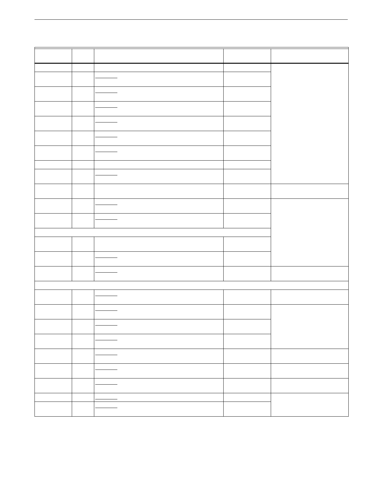
T874 MULTISTAGE THERMOSTATS AND Q674 SUBBASES
87 60-2485—8
Table 10. Y594 Cross Reference.
Model
Number Fig.
No. Description Trade Model
ReplacementaRemarks
Y594A
A1001 46 Obsolete. Amana part no. D68535-11; contains
T874A1077, Q674B1075. T874A1036/
Q674B1075
A1019 82 Obsolete. Amana part no. P68535-12; contains
T874A1077, Q674E1056. T874A1036/
Q674E1049
A1035 44 Obsolete. Trane part no. 268-0187-1; contains
T874A1085, Q674B1018. T874A1036/
Q674B1018
A1043 46 Obsolete. Trane part no. 268-0201-5; contains
T874A1085, Q674B1075. T874A1036/
Q674B1075
A1050 55, 66 Obsolete. Trane part no. 268-0201-3; contains
T874A1085, Q674D1008. T874A1036/
Q674D1040
A1068 82 Obsolete. Sears part no. 42-9144; contains
T874A1119, Q674E1007. T874A1036/
Q674E1049
A1126 64 Contains T874A1291, Q674Q1012. None
A1159 91 Obsolete. Contains T874A1440, Q674G1005. T874A1150/
Q674G1070
A1167 184 California Economizer; Premier White® color;
contains T874A1580 and Q674G1161. T874A1036/
Q674G1070 Replacement is bei
g
e color.
A1175 55 Obsolete. York lo
g
o; part no. 2TH04703224;
contains T874A1622, Q674D1180. T874A1010/
Q674D1040
A1191 46 Obsolete. Amana lo
g
o: part no. P6853524R;
contains T874A1002, Q674B1075. T874A1036/
Q674B1075
Y594B
B1026 44 Trane part no. BAYSTAT012; contains T874B1035,
Q674B1018. T874B1019/
Q674B1018
B1034 46 Obsolete. Trane part no. 163-552-1; contains
T874B1035, Q674B1075. T874B1019/
Q674B1075
B1042 88 Obsolete. Goodman part no. CHTS36-60; contains
T874B1100, Q674E1338. T874B1019/
Q674E1049 No LEDs on replacement.
Y594C
C1009 82 Obsolete. Amana part no. D68535-9; contains
T874C1059, Q674E1056. T874C1018/
Q674E1049 Jumper RC-RH.
C1017 142 Obsolete. Amana part no. D68535-10; contains
T874C1059, Q674F1022. T874C1018/
Q674F1022
C1058 46 Obsolete. Contains T874C1000, Q674B1075. T874C1018/
Q674B1075
C1082 82 Obsolete. Trane part no. 166-162-1; contains
T874C1083, Q674E1007. T874C1018/
Q674E1049
C1256 45 Obsolete. Amana part no. D68535-16; contains
T874C1059, Q674B1059. T874C1018/
Q674B1034 Jumper RC-RH.
C1280 45 Obsolete. Williamson; contains T874C1570,
Q674B1000. T874C1018/
Q674B1034
C1314 56 Obsolete. LSI; contains T874C1471, Q674B1257. T874C1018/
Q674B1018 Jumper RC-RH; no RESET
LED on replacement.
C1322 121 Obsolete. Contains T874C1638, Q674L1561. Y594C1322
C1330 142 Obsolete. Amana part no. D68535-21; contains
T874C1059, Q674F1022. T874C1018/
Q674F1022
aBoth the thermostat and subbase must be replaced.
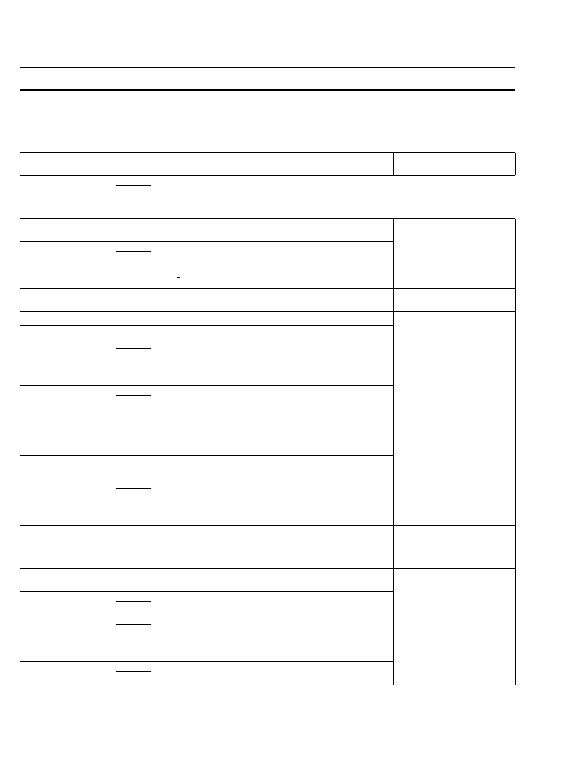
T874 MULTISTAGE THERMOSTATS AND Q674 SUBBASES
60-2485—888
C1348 70 Obsolete. Fiber
g
las; contains T874C1653,
Q674S1000. T874C1000/
Q674B1075 Wirin
g
differences
(
old=new
)
:
Y=Y1;
j
umper RC-RH and Y1-
W1; replacement has no
SERVICE
LED; replacement
has fan switchin
g
and HEAT-
OFF-COOL s
y
stem switchin
g
.
C1355 45 Obsolete. Nord
y
ne “Miller” part no. 9122250;
contains T874C1695, Q674B1000. T874C1018/
Q674B1034
C1363 45 Obsolete. Nord
y
ne “Intertherm” part no. 911100001;
contains T874C1703, Q674B1000. T874C1018/
Q674B1075 Wirin
g
differences
(
old=new
)
:
Y=Y1;
j
umper RC-RH; Y1-W;
replacement has no SERVICE
LED.
C1371 184 Obsolete. California Economizer; contains
T874C1802 and Q674G1005. T874C1018/
Q674G1070
C1389 237 Obsolete. TRADELINE; Premier White® color;
contains T874C1810 and Q674B1547. Y594C1389
C1413 238 Heat Controller “Ener
gy
Ni
g
ht” lo
g
o; contains
T874C1844 and Q674F1592. Y594R1425 E-W2
j
umper re
q
uired; s
y
stem:
EM.HT.-Heat-Off-Cool.
C1421 249 Obsolete. TRADELINE; contains T874C1877 and
Q674B1554. Y594D1347 Replacement has auto
chan
g
eover;
j
umper RH-RC.
C1439 T874C1869 and Q674C1579. None
Y594D
D1016 44 Obsolete. Trane part no. 268-0201-2; contains
T874D1082, Q674B1018. T874D1165/
Q674B1018
D1024 72 Trane part no. BAYSTAT010; contains T874D1082,
Q674C1009. T874D1165/
Q674C1058
D1032 91 Obsolete. Trane part no. BAYSTAT011; contains
T874D1082, Q674G1021. T874D1165/
Q674G1070
D1040 46 Amana part no. P68535-19R; contains T874D1082,
Q674B1075. T874D1165/
Q674B1075
D1057 55, 66 Obsolete. Trane part no. BAYSTAT007; contains
T874D1082, Q674D1008. T874D1165/
Q674D1040
D1149 46 Obsolete. Amana part no. P68535-20C; contains
T874D1322, Q674B1075. T874D1165/
Q674B1075
D1156 48 Obsolete. Trane part no. BAYSTAT013; contains
T874D1082, Q674B1133. T874D1165/
Q674B1018 Replacement has no FILTER
LED.
D1180 82 York part no. 025-23321-000; contains T874D1504,
Q674E1007. T874D1165/
Q674E1049
D1222 166 Obsolete. WeatherKin
g
; contains T874D1009,
Q674F1337. T874D1165/
Q674F1022 Wirin
g
differences
(
old=new
)
:
R=RH;
j
umper RC-RH;
replacement has no EM.HT. or
AUX. HT. LEDs.
D1248 82 Obsolete. Reznor part no. 93437; contains
T874D1629, Q674E1007. T874D1165/
Q674E1049
D1297 82 Obsolete. ArcoAire part no. 1506753; contains
T874D1769, Q674E1346. T874D1165/
Q674E1049
D1305 82 Obsolete. Comfortmaker part no. 1505753; contains
T874D1785, Q674E1346. T874D1165/
Q674E1049
D1321 45 Obsolete. Goodman part no. CHT 90-120; contains
T874D1843, Q674B1000. T874D1165/
Q674B1034
D1339 82 Obsolete. Nord
y
ne part no. 5471180; contains
T874D1009, Q674E1007. T874D1165/
Q674E1049
Table 10. Y594 Cross Reference.
Model
Number Fig.
No. Description Trade Model
ReplacementaRemarks
aBoth the thermostat and subbase must be replaced.
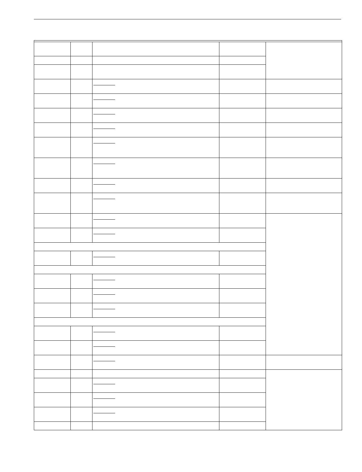
T874 MULTISTAGE THERMOSTATS AND Q674 SUBBASES
89 60-2485—8
D1347 82 TRADELINE® contains T874D1942, Q674E1403. Y594D1347
D1354 82 SUPER TRADELINE® contains T874D2031
(
no
cover
)
, Q674E1049, and TG504A with two ke
y
s. Y594D1354
D1370 45 Obsolete. Carrier part no. 50QE90022101; contains
T874D2049 and Q674B1539. T874D1165/
Q674B1034 Replacement has °F
scaleplate.
D1388 72 Obsolete. Carrier part no. 50QE90023101; contains
T874D2049 and Q674C1520. T874D1165/
Q674C1058 Replacement has °F
scaleplate.
D1396 184 Obsolete. Carrier part no. 50QE90025101; contains
T874D2049 and Q674G1153. T874D1165/
Q674G1070 Replacement has °F
scaleplate.
D1404 55, 66 Obsolete. Carrier part no. 50QE90024101; contains
T874D2049 and Q674D1164. T874D1165/
Q674D1040 Replacement has °F
scaleplate.
D1412 82 Obsolete. Carrier “Weathermaker” part no.
HH07AT209; taupe color; contains T874D2064 and
Q674E1445.
T874D1165/
Q674E1049 Replacement is bei
g
e color.
D1420 82 Obsolete. Carrier “Zone Perfect” part no.
HH07AT208; taupe color; contains T874D2072 and
Q674E1445.
T874D1165/
Q674E1049 Replacement is bei
g
e color.
D1438 55, 66 Obsolete. Contains T874D2098 and Q674D1008. T874D1165/
Q674D1040 Replacement has 2 setpoint
levers.
D1446 55, 66 Obsolete. Contains T874D2106 and Q674D1008. T874D1165/
Q674D1040 Replacement has °F
scaleplate and 2 setpoint
levers.
D1453 208 Obsolete. Amana lo
g
o; part no. P1217501F;
contains T874D2163 and Q674D1172. T874D1165/
Q674D1040
D1461 45 Obsolete. Amana lo
g
o; part no. P1217701F;
contains T874D2171 and Q674B1562. T874D1942/
Q674B1034
Y594E
E1015 72 Obsolete. Trane part no. BAYSTAT015; contains
T874E1040, Q674C1009. T874B1019/
Q674C1058
Y594F
F1022 44 Obsolete. Contains T874F1031 and 40003440-001
wallplate with installed diode. T874F1015
F1048 72 Obsolete. Reznor part no. 93436; contains
T874F1130, Q674C1009. T874F1015/
Q674C1058
F1063 91 Obsolete. Reznor part no. 93435; contains
T874F1130, Q674G1005. T874F1015/
Q674G1070
Y594G
G1013 160 Obsolete. York part no. 2TH11702424; contains
T874G1170, Q674J1027. Y594G1567
G1138 160 Obsolete. York part no. 025-22286; contains
T874G1196, Q674J1027. Y594G1567
G1153 154 Obsolete. Crispaire part no. HP10-51; contains
T874G1089, Q674F1204. Y594G1252 Wirin
g
differences
(
old=new
)
:
A=L.
G1161 162 Contains T874G1204, Q674J1043. Y594G1161
G1195 155 Obsolete. Heil Quaker part no. HQ521387HW;
contains T874G1246, Q674F1212. Y594G1252
G1229 160 Obsolete. York part no. 6TH11702424; contains
T874G1428, Q674J1027. Y594G1567
G1245 155 Obsolete. BDP part no. HH641502; contains
T874G1451, Q674F1212. Y594G1252
G1252 155 TRADELINE; contains T874G1246, Q674F1212. Y594G1252
Table 10. Y594 Cross Reference.
Model
Number Fig.
No. Description Trade Model
ReplacementaRemarks
aBoth the thermostat and subbase must be replaced.
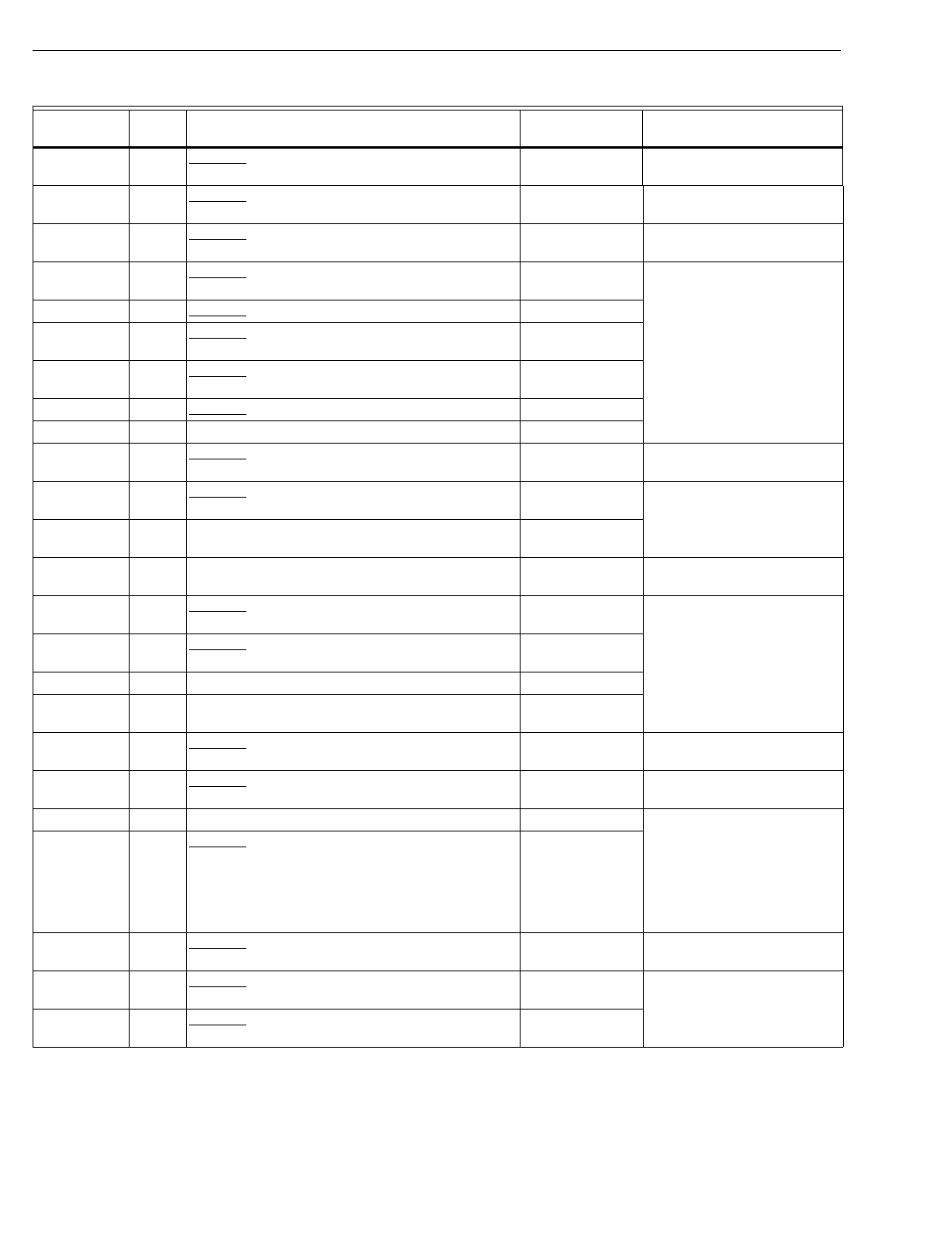
T874 MULTISTAGE THERMOSTATS AND Q674 SUBBASES
60-2485—890
G1294 79 Obsolete. LSI; contains T874G1378, Q674C1124. See OEM for
replacement. H2 is ni
g
ht setback.
G1328 194 Obsolete. Addison part no. 8403-197; contains
T874G1543, Q674F1345. Y594G1252 Wirin
g
differences
(
old=new
)
:
Y1=O, X=L, C=X.
G1344 194 Obsolete. Heat Controller part no. 7601-110B;
contains T874G1469, Q674F1345. Y594G1252 Wirin
g
differences
(
old=new
)
:
Y1=O, X=L, C=X; W1=Y.
G1351 160 Obsolete. Luxaire part no. 026-00068-000; contains
T874G1568, Q674J1126. Y594G1567
G1369 155 Obsolete. Contains T874G1246, Q674F1212. Y594G1252
G1377 169 Obsolete. Coleman part no. 3600-373; contains
T874G1576, Q674F1402. Y594G1633
G1385 155 Obsolete. ArcoAire; contains T874G1592,
Q674F1212. Y594G1252
G1393 170 Obsolete. Contains T874R1393, Q674L1454. Y594G1393
G1419 227 TRADELINE; contains T874G1642, Q674F1444. Y594G1419
G1427 177 Obsolete. Mammoth part no. 73034101; contains
T874G1659, Q674C1330. See OEM for
replacement. H2 is ni
g
ht setback.
G1443 174 Obsolete. American Standard
(
Trane
)
part no.
ASYSTAT650; contains T874G1675, Q674J1142. Y594G1161
G1476 227 TRADELINE; same as Y594G1419 except Premier
White® color; contains T874G1741, Q674F1477. Y594G1476
G1492 211 Trol-A-Temp; contains T874G1758, Q674F1485. None See Trol-A-Temp for
replacement.
G1500 216 Obsolete. Comfortmaker part no. 1505756; contains
T874G1774, Q674J1175. See OEM for
replacement.
G1518 216 Obsolete. ArcoAire part no. 1506756; contains
T874G1782, Q674J1175. See OEM for
replacement.
G1526 167 TRADELINE; contains T874G1626, Q674F1436. None
G1534 227 TRADELINE; °C; white; Australia; contains
T874G1824, Q674F1477. None
G1542 231 Obsolete. Intertherm part no. 9129290; contains
T874G1832, Q674F1519. Y594G1252 Coolin
g
chan
g
eover onl
y
.
G1559 231 Obsolete. Miller part no. 9129310; contains
T874G1840, Q674F1519. Y594G1252 Coolin
g
chan
g
eover onl
y
.
G1567 160 TRADELINE; contains T874G1865, Q674J1209. Y594G1567
G1575 160 Obsolete. TRADELINE; same as Y594G1567
except Premier White® color; contains T874G1873,
Q674J1225; direct replacement for York
2TH11702424
(
Y594G1013 contains T874G1170/
Q674J1027
)
and 6TH11702424
(
Y594G1229
contains T874G1428/Q674J1027
)
.
Y594G1567 Replacement is bei
g
e.
G1583 229 Obsolete. Lennox Canada part no. 97E78; contains
T874G1857, Q674F1535. Y594G1161 Wirin
g
differences
(
old=new
)
:
E=X2, C=B, L=F.
G1591 243 Obsolete. Amana part no. 10636701; contains
T874G1899 and Q674F1550. Y594G1633
G1609 155 Obsolete. Econar; contains T874G1915 and
Q674F1212. Y594G1252
Table 10. Y594 Cross Reference.
Model
Number Fig.
No. Description Trade Model
ReplacementaRemarks
aBoth the thermostat and subbase must be replaced.
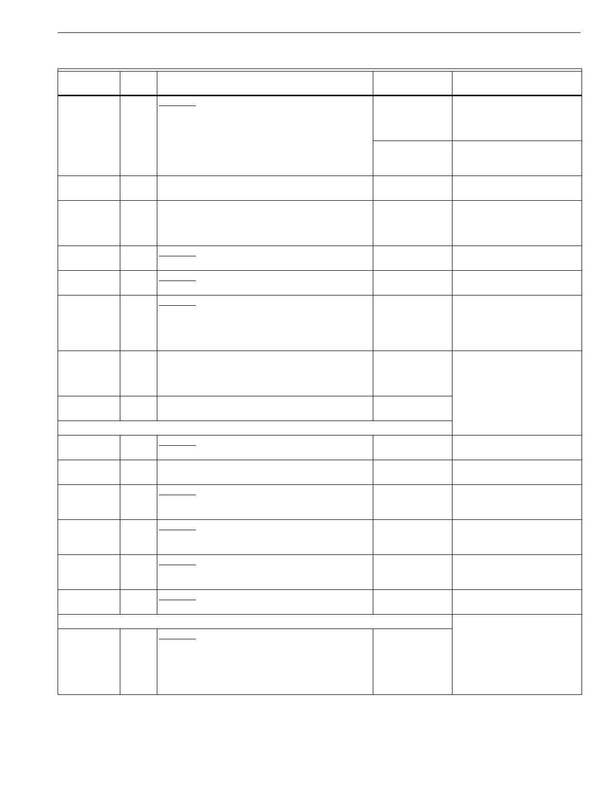
T874 MULTISTAGE THERMOSTATS AND Q674 SUBBASES
91 60-2485—8
G1617 73 Obsolete. Carrier part no. 50QE90020101; contains
T874G1949 and Q674C1504. Y594H1012aWirin
g
differences
(
old=new
)
:
Y1=O, Y2=Y, L=R, R=none;
R-L
j
umper re
q
uired; no ni
g
ht
setback.
T8600D2028
(
pro
g
rammable
)
Wirin
g
differences
(
old=new
)
:
Y1=O, Y2=Y, L=R; W-Y
j
umper
re
q
uired; ni
g
ht setback.
G1625 160 York Canada part no. 2TH11702524; contains
T874G1964 and Q674J1266. Y594G1567aReplacement has °F
scaleplate.
G1633 169 TRADELINE; contains T874G1972 and
Q674F1584; direct replacement for Y594G1377
(
T874G1576/Q674F1402
)
Evcon/Coleman part no.
3600-373.
Y594G1633a
G1641 169 Obsolete. Amana part no. 10636703; contains
T874G1980 and Q674F1600. Y594G1633 Wirin
g
differences
(
old=new
)
:
W3=W2.
G1658 155 Obsolete. Tempstar “Inter-Cit
y
Products” part no.
1149910; contains T874G1998 and Q674F1212. Y594G1252
G1666 103 Obsolete. TRADELINE; manual chan
g
eover;
contains T874G2004 and Q674L1892; direct
replacement for Y507J1011
(
T874G1055/
Q674L1041
)
Carrier part no. 99TZ90041106
(
HH07AT171/HH93AZ1750
)
.
Y594G1674 Replacement has auto
chan
g
eover.
G1674 161 TRADELINE; automatic chan
g
eover; contains
T874G2004 and Q674J1274; direct replacement
Y507J1003
(
T874G1055/Q674J1035
)
Carrier part
no. 99TZ90040106
(
HH07AT171/HH93AZ173
)
.
Y594G1674
G1716 155 WaterFurnace lo
g
o; part no. TA21H03; contains
T874G2046 and Q674F1667. Y594G1716
Y594H
H1004 79 Obsolete. LSI part no. 73033901; contains
T874H1039 and Q674C1124. T8600D2028 H2 is ni
g
ht setback.
H1012 164 Contains T874H1062 and Q674C1249; replaces
T874H1005/Q674C1041. Y594H1012
H1020 177 Obsolete. Mammoth part no. 71117101; contains
T874H1096 and Q674C1330. Y594H1012 Wirin
g
differences
(
old=new
)
:
R1=R, R2=L; use
j
umper
provided.
H1038 74 Obsolete. Carrier part no. 50QE90019101; contains
T874H1161 and Q674C1496. Y594H1012aWirin
g
differences
(
old=new
)
:
X1=O, Y2=Y; L-R
j
umper
re
q
uired.
H1046 172 Obsolete. Carrier part no. 50QE90026101; contains
T874H1153 and Q674B1406. T874A1130/
Q674B1075a
Wirin
g
differences
(
old=new
)
:
Y=Y1; W1-Y1
j
umper re
q
uired;
replacement has no LEDs.
H1053 173 Obsolete. Carrier part no. 50QE90027101; contains
T874H1153 and Q674C1322. Y594H1012aWirin
g
differences
(
old=new
)
:
Z=X.
Y594J
J1001 241 Obsolete. TRADELINE; manual chan
g
eover;
contains T874J1069 and Q674L1900; direct
replacement for T874J1002 or T874A1028 used
with Q674L1074 or Q674L1637
(
HH07AT175 or
HH07AT165 used with HH93AZ186 or
HH93AZ195
)
.
(
Recontrol
)
T8511G1021
Table 10. Y594 Cross Reference.
Model
Number Fig.
No. Description Trade Model
ReplacementaRemarks
aBoth the thermostat and subbase must be replaced.
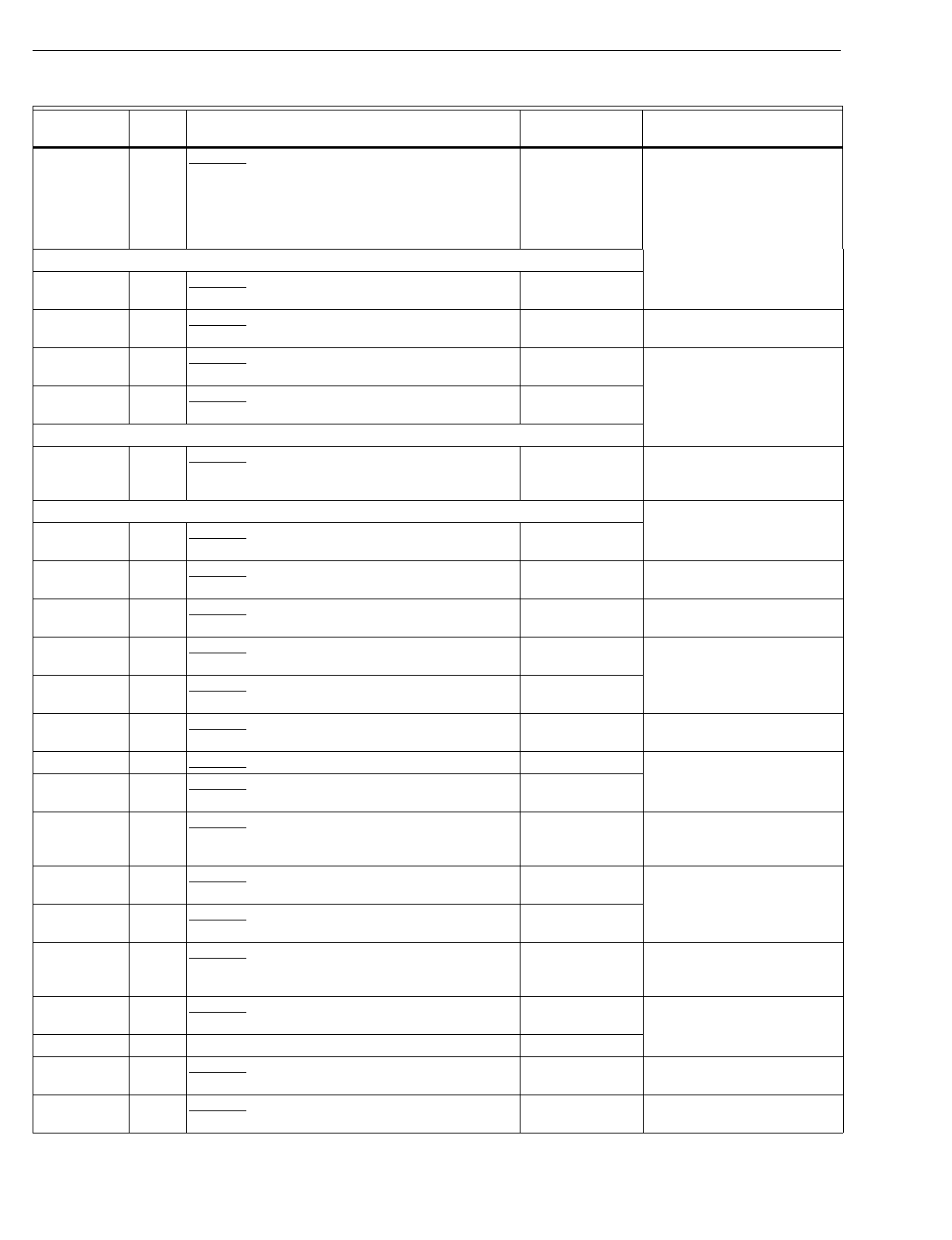
T874 MULTISTAGE THERMOSTATS AND Q674 SUBBASES
60-2485—892
J1019 244 Obsolete. TRADELINE; automatic chan
g
eover;
contains T874J1069 and Q674J1282; direct
replacement for T874J1002 or T874J1028 used
with Q674J1068 or Q674J1159
(
HH07AT175 or
HH07AT165 used with HH93AZ183 or
HH93AZ196
)
.
(
Recontrol
)
T8511G1021
Y594N
N1007 178 Obsolete. Williamson part no. 75-189; contains
T874N1008 and Q674F1196. T874N1016/
Q674F1196
N1015 179 Obsolete. Contains T874N1040 and Q674F1261. Y594G1419aWirin
g
differences
(
old=new
)
:
L=X2, Y=Y1.
N1023 178 Obsolete. Intertherm part no. 9111882; contains
T874N1057 and Q674F1220. T874N1016/
Q674F1220
N1031 178 Obsolete. Nord
y
ne “Miller” part no. 9122240;
contains T874N1065 and Q674F1220. T874N1016/
Q674F1220
Y594P
P1005 97 Obsolete. Carrier part no. 50QE90021101; contains
T874P1055 and Q674C1512. T8600D2028 Wirin
g
differences
(
old=new
)
:
Y=Y1, W=O; Y1-W1
j
umper
re
q
uired.
Y594R
R1011 120 Obsolete. York part no. 2TH11702224; contains
T874R1046 and Q674L1272. Y594R1664
R1029 47 Obsolete. Br
y
ant; contains T874R1004 and
Q674B1042. Y594R1243 Wirin
g
differences
(
old=new
)
:
W1=W2.
R1037 122 Obsolete. Fedders part no. 88-58-00540-001;
contains T874R1269 and Q674L1066. Y594R1615 Wirin
g
differences
(
old=new
)
:
K=E, C=X, W1=B, Z=L.
R1102 120 Obsolete. York part no. 025-22285-000; contains
T874R1145 and Q674L1272. Y594R1664
R1110 108 Obsolete. Heil Quaker part no. HQ712004HW;
contains T874R1137 and Q674L1132. Y594R1292
R1128 116 Obsolete. Crispaire part no. HP9-51; contains
T874R1111 and Q674L1215. Y594R1243 Wirin
g
differences
(
old=new
)
:
A=L.
R1136 109 Obsolete. Contains T874R1053 and Q674L1140. Y594R1763
R1151 120 Obsolete. York part no. 2TH11702324; contains
T874R1251, Q674L1272 and C815A1039. Y594R1672
R1185 201 Obsolete. Intertherm part no. 9111871; contains
T874R1202 and Q674L1264. Y594R1672 Wirin
g
differences
(
old=new
)
:
W2=W, X=B, Z=no
connection, K=X, W1=H.
R1193 120 Obsolete. York part no. 6TH11702224; contains
T874R1327 and Q674L1272. Y594R1664
R1201 106 Obsolete. BDP part no. HH641501; contains
T874R1335 and Q674L1405. Y594R1243
R1219 133 Obsolete. Fedders part no. 88-58-00560-001;
contains T874R1343 and Q674L1413. Y594R1425 Wirin
g
differences
(
old=new
)
:
K=E, C=X, Z=L; remove
factor
y
installed
j
umper.
R1235 125 Obsolete. Coleman part no. 3600-368; contains
T874R1368 and Q674L1421. Y594R1797
R1243 115 TRADELINE; contains T874R1152 and Q674L1207. Y594R1243
R1250 128 Obsolete. Williamson part no. 75-191; contains
T874R1392 and Q674L1447. Y594R1425 Wirin
g
differences
(
old=new
)
:
A=L.
R1284 136 Obsolete. Trane part no. BAYSTAT339; contains
T874R1426 and Q674L1496. Y594R1763
Table 10. Y594 Cross Reference.
Model
Number Fig.
No. Description Trade Model
ReplacementaRemarks
aBoth the thermostat and subbase must be replaced.
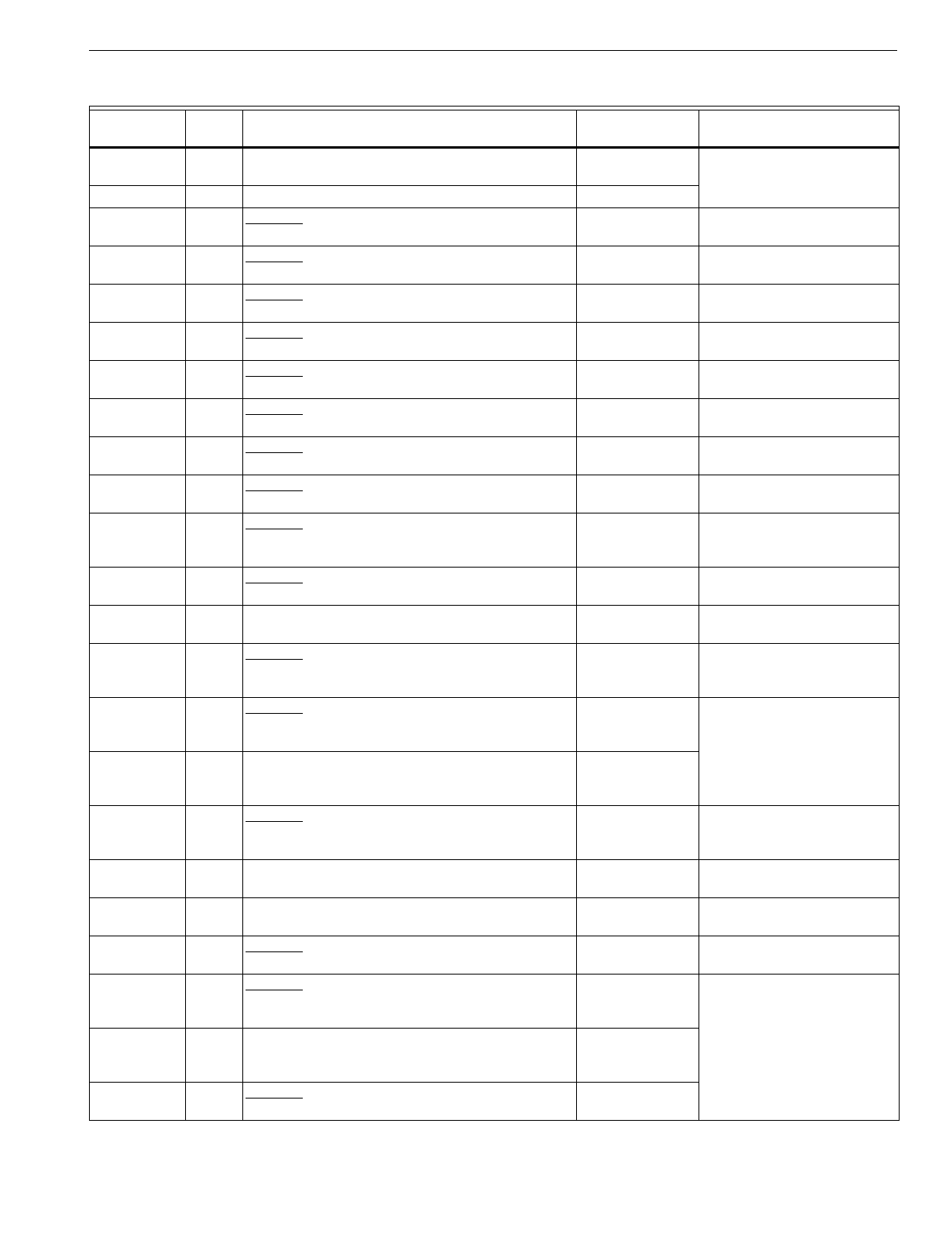
T874 MULTISTAGE THERMOSTATS AND Q674 SUBBASES
93 60-2485—8
R1292 108 Contains T874R1467 and Q674L1512; replaces
Y594R1110
(
T874R1137/Q674L1132
)
.Y594R1292
R1300 123 Contains T874R1475 and Q674L1520. Y594R1300
R1318 130 Obsolete. Comfortmaker part no. 1505721; contains
T874R1483, Q674L1538 and C815A1005. Y594R1763 Wirin
g
differences
(
old=new
)
:
W1=W, E=X2, X=F, C=B.
R1326 137 Obsolete. SUPER TRADELINE; contains
T874R1491 and Q674L1553. Y594R1615
R1334 47 Obsolete. Slant Fin; contains T874R1509 and
Q674B1042. Y594R1243 Wirin
g
differences
(
old=new
)
:
W1=W2.
R1342 130 Obsolete. ArcoAire part no. 1506721; contains
T874R1517, Q674L1538 and C815A1005. Y594R1763 Wirin
g
differences
(
old=new
)
:
W1=W, E=X2, X=F, C=B.
R1359 113 Obsolete. ArcoAire part no. A02074; contains
T874R1525 and Q674L1181. Y594R1243 Wirin
g
differences
(
old=new
)
:
X1=X.
R1375 130 Obsolete. Contains T874R1566, Q674L1538 and
C815A1005. Y594R1763 Wirin
g
differences
(
old=new
)
:
W1=W, E=X2, X=F, C=B.
R1383 132 Obsolete. Comfortmaker part no. 1505739; contains
T874R1574 and Q674L1538. Y594R1243 Wirin
g
differences
(
old=new
)
:
W=W2, C=X, X=L.
R1391 132 Obsolete. ArcoAire part no. 1506739; contains
T874R1582 and Q674L1538. Y594R1243 Wirin
g
differences
(
old=new
)
:
W=W2, C=X, X=L.
R1409 119 Obsolete. Intertherm part no. 6244630; contains
T874R1608 and Q674L1264. Y594R1763 Wirin
g
differences
(
old=new
)
:
W2=W, X=B, Z=F, K=X2,
W1=O.
R1417 113 Obsolete. Comfortmaker part no. 1505-735;
contains T874R1301 and Q674L1181. Y594R1243 Wirin
g
differences
(
old=new
)
:
X1=X.
R1425 168 SUPER TRADELINE; contains T874R1616 and
Q674L1587. Y594R1425
R1433 200 Obsolete. Miller part no. 9115900; contains
T874R1624 and Q674L1595. Y594R1243 Wirin
g
differences
(
old=new
)
:
W2=W, X=B, Z=F, K=X2,
W1=O.
R1441 136 Obsolete. American Standard
(
Trane
)
part no.
ASYSTAT651; contains T874R1657 and
Q674L1611.
Y594R1763
R1466 108 Heil Quaker part no. 1060321; model no.
HAXB004TW01; contains T874R1673 and
Q674L1132.
Y594R1292
R1482 119 Obsolete. Nord
y
ne “Miller” part no. 9122230;
contains T874R1699 and Q674L1264. Y594R1763 Wirin
g
differences
(
old=new
)
:
W2=W, X=B, Z=F, K=X2,
W1=O.
R1490 209 Trol-A-Temp; contains T874R1707 and Q674L1678. None See Trol-A-Temp for
replacement.
R1508 209 Trol-A-Temp; contains T874R1715 and Q674L1686. None See Trol-A-Temp for
replacement.
R1516 132 Obsolete. Sn
y
der General part no. 654958B07;
contains T874R1723, Q674L1702 and C815A1005. Y594R1763 Wirin
g
differences
(
old=new
)
:
W1=W, C=B, X=X2.
R1524 108 Obsolete. Inter-Cit
y
Products part no.
HQ1147925HW; contains T874R1731 and
Q674L1132.
Y594R1292
R1532 108 Heil Quaker part no. 1060322; model no.
TAXB004TW01; contains T874R1749 and
Q674L1132.
Y594R1292
R1607 108 Obsolete. Keeprite THPC; contains T874R1814 and
Q674L1132. Y594R1292
Table 10. Y594 Cross Reference.
Model
Number Fig.
No. Description Trade Model
ReplacementaRemarks
aBoth the thermostat and subbase must be replaced.
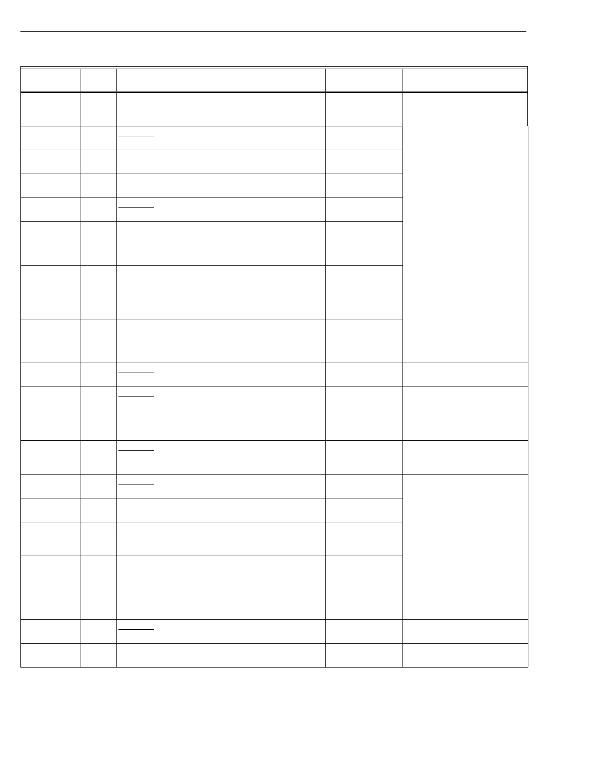
T874 MULTISTAGE THERMOSTATS AND Q674 SUBBASES
60-2485—894
R1615 230 TRADELINE; contains T874R1822 and
Q674L1710; replaces Y594R1326
(
T874R1491/
Q674L1553
)
.
Y594R1615
R1623 134 Obsolete. Rheem Universal Parts part no. 41-
20796-46; contains T874R1558 and Q674L1504. Y594R1300
R1631 134 Rheem part no. 41-20796-29; contains T874R1442
and Q674L1504. Y594R1300
R1649 134 Ruud part no. 41-20796-33; contains T874R1434
and Q674L1504. Y594R1300
R1656 134 Obsolete. WeatherKin
g
part no. 41-20796-64;
contains T874R1830 and Q674L1504. Y594R1300
R1664 120 TRADELINE; contains T874R1871 and
Q674L1736; direct replacement for York
2TH11702224
(
Y594R1011 contains T874R1046/
Q674L1272
)
.
Y594R1664
R1672 120 TRADELINE; contains T874R1889, Q674L1736
and C815A1054; direct replacement for York
2TH11702324
(
Y594R1151 contains T874R1251/
Q674L1272/C815A1039
)
and 6TH11702224
(
Y594R1193 contains T874R1327/Q674L1272
)
.
Y594R1672
R1680 230 TRADELINE; same as Y594R1615 except Premier
White® color; contains T874R1897 and
Q674L1751; direct replacement for Y594R1326
(
T874R1491/Q674L1553
)
.
Y594R1680
R1698 120 Obsolete. TRADELINE; Premier White® color;
contains T874R1905, Q674L1777 and C815A1054. Y594R1672 Replacement is bei
g
e.
R1706 120 Obsolete. TRADELINE; same as Y594R1664
except Premier White® color; contains T874R1913
and Q674L1777; direct replacement for Y594R1011
(
T874R1046/Q674L1272
)
York part no.
2TH11702224.
Y594R1664 Replacement is bei
g
e.
R1714 228 Obsolete. Lennox part no. 97E79; Canada; Premier
White® color; contains T874R1855 and
Q674L1728.
Y594R1763 Wirin
g
differences
(
old=new
)
:
Y1=Y, L=F, W1=W, E=W2,
C=B.
R1722 115 Obsolete. Econar; contains T874R1921 and
Q674L1207. Y594R1243a
R1748 197 American Standard
(
Trane
)
part no. ASYSTAT651A;
contains T874R1939 and Q674L1801. Y594R1763a
R1755 168 Obsolete. Inter-Cit
y
Products part no.
HQ1149376HW; contains T874R1947 and
Q674L1819.
Y594R1425a
R1763 197 TRADELINE: contains T874R1954 and
Q674L1827; direct replacement for Y594R1136
(
T874R1053/Q674L1140
)
, Y594R1748
(
T874R1939/Q674L1801
)
Trane part no.
ASYSTAT651A, Y594R1441
(
T874R1657/
Q674L1611
)
Trane part no. ASYSTAT651.
Y594R1763
R1771 115 Obsolete. Consolidated Industries part no.
9036100; contains T874R1962 and Q674L1843. Y594R1680aIncludes CHECK LED.
R1789 120 York Canada part no. 2TH11701524; contains
T874R1970 and Q674L1850. Y594R1672aReplacement has °F
scaleplate.
Table 10. Y594 Cross Reference.
Model
Number Fig.
No. Description Trade Model
ReplacementaRemarks
aBoth the thermostat and subbase must be replaced.
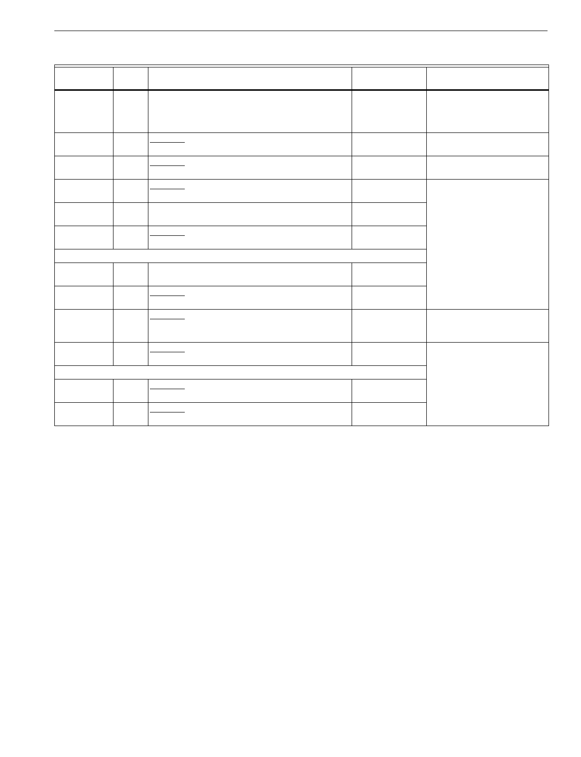
T874 MULTISTAGE THERMOSTATS AND Q674 SUBBASES
95 60-2485—8
R1797 125 TRADELINE; contains T874R1988 and
Q674L1868; direct replacement for Y594R1235
(
T874R1368/Q674L1421
)
Evcon/Coleman part no.
3600-368
)
.
Y594R1797a
R1805 245 Obsolete. Amana part no. 10636702; contains
T874R2002 and Q674L1876. Y594R1797 Wirin
g
differences
(
old=new
)
:
C/X=X.
R1813 245 Obsolete. Amana part no. 10636704; contains
T874R2010 and Q674L1884. Y594R1797 Wirin
g
differences
(
old=new
)
:
C/X=X, W3=W2.
R1821 125 Obsolete. York lo
g
o; part no. 2TH11703424A;
contains T874R2028 and Q674L1918. Y594R1797
R1839 134 Rudd lo
g
o; part no. 41-20796-48; contains
T874R2036 and Q674L1504. See OEM for
replacement.
R1854 123 Obsolete. Rheem lo
g
o; part no. 41-20796-47;
contains T874R1996 and Q674L1504. Y594R1300
Y594W
W1014 54 Contains T874W1015, Q674B1216 and
C815A1005. Y594W1014
W1022 140 Obsolete. Rheem part no. 41-20797-19; contains
T874W1031, Q674L1546 and C815A1005. T8611M2025.
W1030 68 Obsolete. Inter-Cit
y
Products part no. 1072350;
contains T874W1072, Q674L1835 and C815A1005
Outdoor Thermistor.
T8611M2025
(
pro
g
rammable
)
Includes ni
g
ht setback.
W1055 247 Obsolete. Addison lo
g
o; part no. 843-277; contains
T874W1106, Q674L1934 and C815A1005. T8611M2025
Y594Y
Y1004 210 Obsolete. Mammoth part no. 71117301; contains
T874Y1005 and Q674E1353. See OEM for
replacement.
Y1012 248 Obsolete. WaterFurnace lo
g
o; part no. TA21H03;
contains T874Y1013 and Q674F1675.
Table 10. Y594 Cross Reference.
Model
Number Fig.
No. Description Trade Model
ReplacementaRemarks
aBoth the thermostat and subbase must be replaced.
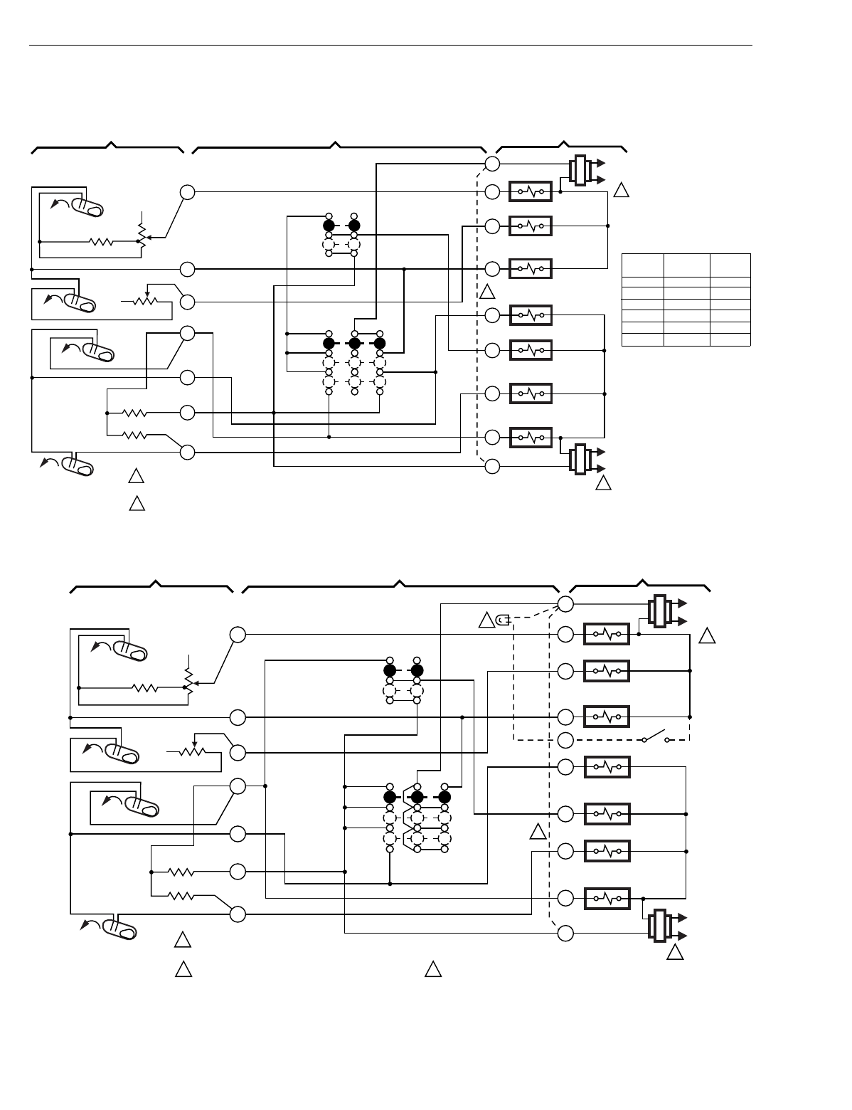
T874 MULTISTAGE THERMOSTATS AND Q674 SUBBASES
60-2485—896
WIRING DIAGRAMS
Fig. 44. Schematic and hookup of T874A,B,C,D,E,F with Q674B. Used in standard applications.
Fig. 45. Schematic and hookup of T874C,D with Q674B. Used in standard applications.
H1
FALL
L1
(HOT)
L2
1
RH
W1
W2
O
G
Y2
Y1
RC
HEAT RELAY 2
HEAT RELAY 1
HEAT
OFF
COOL
SYSTEM
SWITCH
H1 ANTICIPATOR
C1 ANTICIPATOR
AUTO
ON
FAN
SWITCH
2
1POWER SUPPLY. PROVIDE DISCONNECT MEANS AND OVERLOAD
PROTECTION AS REQUIRED.
JUMPER RH, RC FOR SINGLE TRANSFORMER.
2
M2903
B
HEAT CHANGEOVER
VALVE
L1
(HOT)
L2
1
COOL CHANGEOVER
VALVE
FAN RELAY
COMPRESSOR
CONTACTOR 2
COMPRESSOR
CONTACTOR 1
1
4
6
8
9
10
11
H2
FALL
C2 ANTICIPATOR
RISE
RISE
C1
C2
THERMOSTAT SUBBASE SYSTEM COMPONENTS
H2 ANTICIPATOR
NOTE:
Model Heating Cool-
ing
No. Bulbs Bulbs
T874A H1 C1
T874B H1 C1,C2
T874C H1,H2 C1
T874D H1,H2 C1,C2
T874E C1,C2
T874D H1,H2
H1
FALL
L1
(HOT)
L2
1
RH
W1
W2
O
G
Y2
Y1
RC
HEAT RELAY 2
HEAT RELAY 1
HEAT
OFF
COOL
SYSTEM
SWITCH
H1 ANTICIPATOR
C1 ANTICIPATOR
AUTO
ON
FAN
SWITCH
2
1POWER SUPPLY. PROVIDE DISCONNECT MEANS AND OVERLOAD
PROTECTION AS REQUIRED.
JUMPER RH, RC FOR SINGLE TRANSFORMER.
2
M933C
B
HEAT CHANGEOVER
VALVE
L1
(HOT)
L2
1
COOL CHANGEOVER
VALVE
FAN RELAY
COMPRESSOR
CONTACTOR 2
COMPRESSOR
CONTACTOR 1
1
4
6
8
9
10
11
H2
FALL
C2 ANTICIPATOR
RISE
RISE
C1
C2
X1
3OPTIONAL LED ON SOME MODELS.
THERMOSTAT SUBBASE SYSTEM COMPONENTS
3
H2 ANTICIPATOR
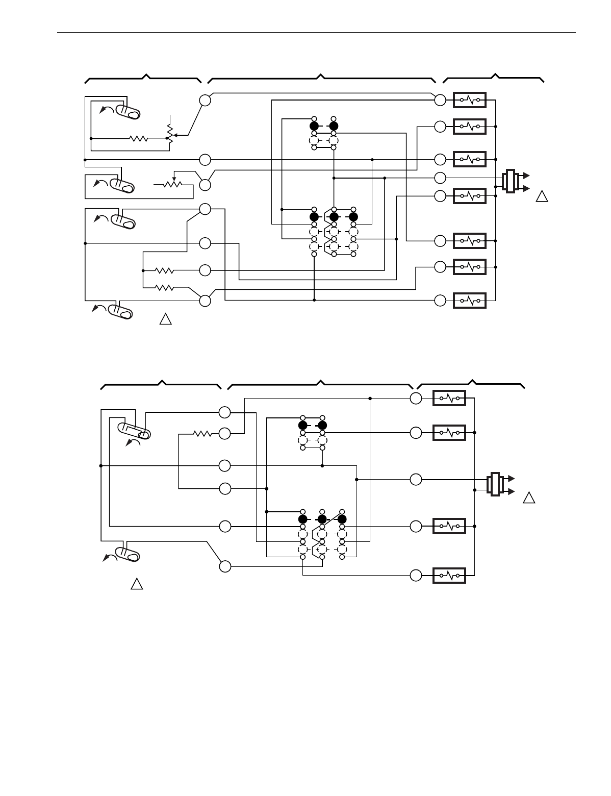
T874 MULTISTAGE THERMOSTATS AND Q674 SUBBASES
97 60-2485—8
Fig. 46. Schematic and hookup of T874A,B,D with Q674B. Used in standard applications.
.
Fig. 47. Schematic and hookup of T874R with Q674B. Used in heat pump applications.
H1
FALL
W1
W2
O
G
Y2
Y1
HEAT RELAY 2
HEAT RELAY 1
HEAT
OFF
COOL
SYSTEM
SWITCH
H1 ANTICIPATOR
C1 ANTICIPATOR
AUTO
ON
FAN
SWITCH
1POWER SUPPLY. PROVIDE DISCONNECT MEANS AND OVERLOAD
PROTECTION AS REQUIRED.
M2904
B
HEAT CHANGEOVER
VALVE
COOL
CHANGEOVER
VALVE
FAN RELAY
COMPRESSOR
CONTACTOR 2
COMPRESSOR
CONTACTOR 1
1
4
6
8
9
10
11
H2
FALL
C2 ANTICIPATOR
RISE
RISE
C1
C2
L1
(HOT)
L2
1
R
THERMOSTAT SUBBASE SYSTEM COMPONENTS
H2 ANTICIPATOR
L1
(HOT)
L2 1
COOL
HEAT
FALL
O
G
R
W1
Y
H1/C1
ANTICIPATOR
H2
SYSTEM
SWITCH
FAN RELAY
1POWER SUPPLY. PROVIDE DISCONNECT MEANS AND
OVERLOAD PROTECTION AS REQUIRED. M2906
OFF
COOL CHANGEOVER
VALVE
H1
FALL
C1
FAN
SWITCH
AUTO
ON
THERMOSTAT SUBBASE SYSTEM COMPONENTS
1
2
3
4
5
6
AUX. HT.
RELAY
COMPRESSOR
CONTACTOR
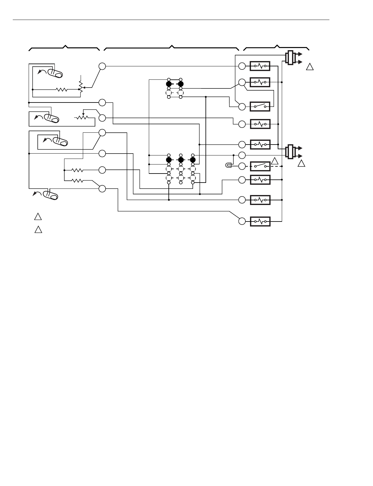
T874 MULTISTAGE THERMOSTATS AND Q674 SUBBASES
60-2485—898
Fig. 48. Schematic and hookup of T874D with Q674B. Used in standard applications.
H1
FALL
W1
G
W2
B
RH
X1
O
FAN RELAY
HEAT RELAY 1
HEAT
OFF
COOL
SYSTEM
SWITCH
H1 ANTICIPATOR
C1 ANTICIPATOR
AUTO
ON
FAN
SWITCH
2
1POWER SUPPLY. PROVIDE DISCONNECT MEANS AND OVERLOAD
PROTECTION AS REQUIRED.
CLOGGED FILTER, SERVICE SWITCH. M2905
THERMOSTAT SUBBASE SYSTEM COMPONENTS
RC
HEAT CHANGEOVER
VALVE
L1
(HOT)
L2
1
COOL CHANGEOVER
VALVE
COMPRESSOR
CONTACTOR 2
COMPRESSOR
CONTACTOR 1
1
4
6
8
9
10
11
H2
FALL
C2 ANTICIPATOR
RISE
RISE
C1
C2 Y1
Y2
HEAT RELAY 2
EXTERNAL
FAN SWITCH
2
L1
(HOT)
L2
1
FILTER
LED (RED)
H2
ANTICIPATOR
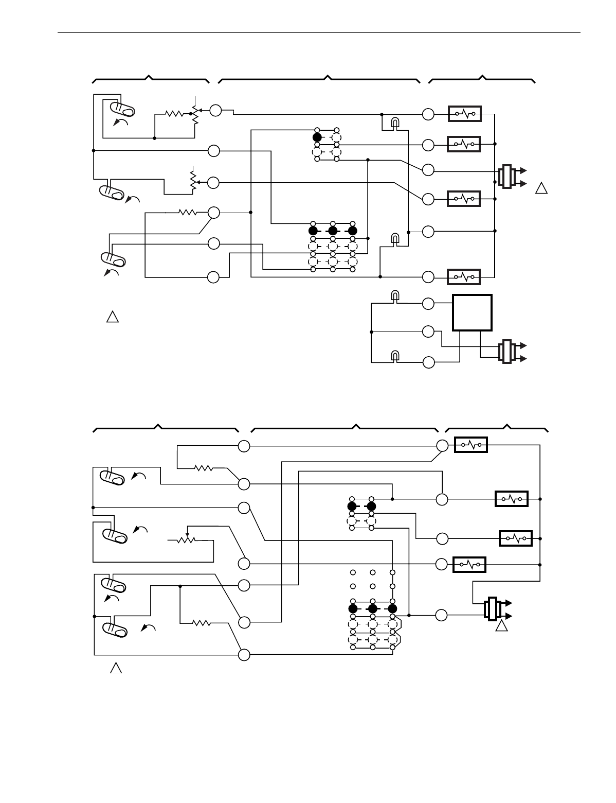
T874 MULTISTAGE THERMOSTATS AND Q674 SUBBASES
99 60-2485—8
Fig. 49. Schematic and hookup of T874C with Q674B. Used in standard applications.
Fig. 50. Schematic and hookup of T874G with Q674B. Used in heat pump applications.
L1
(HOT)
L2
1
H1
FALL
H2
FALL
C1
RISE
L1
(HOT)
L2 1
POWER SUPPLY. PROVIDE DISCONNECT MEANS AND OVERLOAD
PROTECTION AS REQUIRED.
HEAT RELAY 1
BLOWER RELAY
HEAT RELAY 2
COMPRESSOR
CONTACTOR
HSII
CONTROL
PANEL
LO SPEED
LED (GREEN)
HI SPEED
LED (GREEN
COOL LED
(YELLOW)
HEAT
LED (RED)
FAN SWITCH
AUTO
ON
SYSTEM
SWITCH
HEAT
OFF
COOL
C1 ANTICIPATOR
H2 ANTICIPATOR
H1
ANTICIPATOR
1
4
6
8
9
10
W1
G
R
W2
T
Y1
L
C
H
M5945
THERMOSTAT SUBBASE SYSTEM COMPONENTS
H1 FALL
H2
FALL
CO
RISE
C1 RISE
L1
(HOT)
L2
1
1POWER SUPPLY. PROVIDE DISCONNECT MEANS AND OVERLOAD PROTECTION AS REQUIRED.
THERMOSTAT SUBBASE SYSTEM COMPONENTS
H1
ANTICIPATOR
H2 ANTICIPATOR
C1 ANTICIPATOR
10
9
8
6
4
2
1
FAN
SWITCH
AUTO
ON
SYSTEM
SWITCH
HEAT
OFF
COOL
R
W2
AUX. HT. RELAY
G
FAN RELAY
Y
COMPRESSOR
CONTRACTOR
O
COOL CHANGEOVER
VALVE
M8000
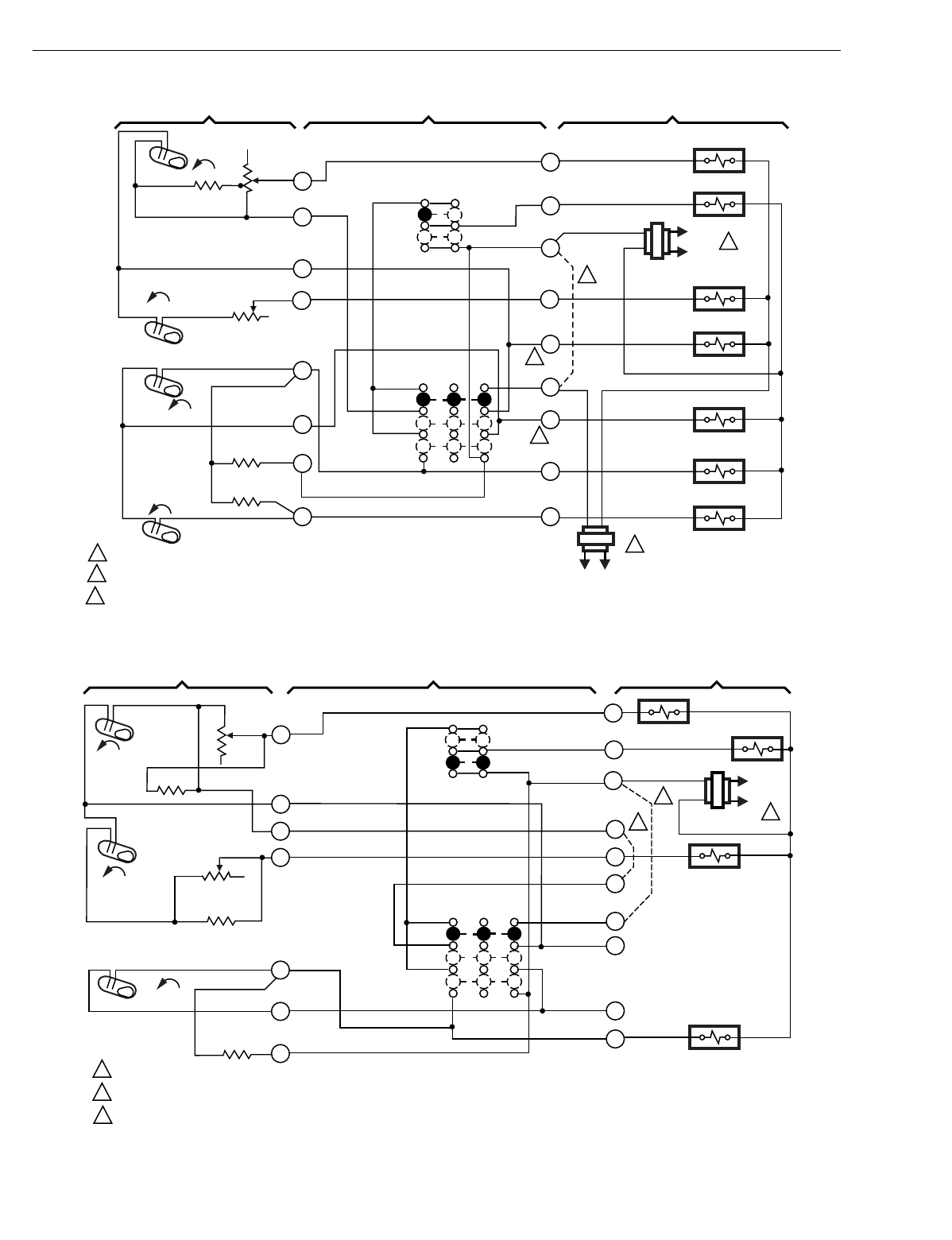
T874 MULTISTAGE THERMOSTATS AND Q674 SUBBASES
60-2485—8100
Fig. 51. Schematic and hookup of T874D with Q674B. Used in standard applications.
Fig. 52. Schematic and hookup of T874C with Q674B. Used in standard applications.
C2
RISE
L1
(HOT)
L2 1
L1
(HOT)
L2
1
3
3
C1
RISE
H2
FALL
H1
FALL
M5944
H1 ANTICIPATOR
H2 ANTICIPATOR
C1 ANTICIPATOR
C2 ANTICIPATOR
POWER SUPPLY. PROVIDE DISCONNECT MEANS AND OVERLOAD PROTECTION AS REQUIRED.
FIELD WIRE JUMPER TO ALLOW SINGLE SYSTEM TRANSFORMER.
B, O TERMINALS ON SOME MODELS.
1
2
3
1
3
4
6
8
9
10
11 Y2
Y1
O
RH
B
W2
RC
G
W1
2
SYSTEM
SWITCH
HEAT
OFF
COOL
ON
AUTO
FAN
SWITCH
HEAT RELAY 1
FAN RELAY
HEAT RELAY 2
HEAT CHANGEOVER VALVE
COOL CHANGEOVER VALVE
COMPRESSOR CONTACTOR 1
COMPRESSOR CONTACTOR 2
THERMOSTAT SUBBASE SYSTEM COMPONENTS
H1
FALL
H2
FALL
C1 RISE
L1
(HOT)
L2
1
2
3
1
2
3
POWER SUPPLY. PROVIDE DISCONNECT MEANS AND OVERLOAD PROTECTION AS REQUIRED.
OPTIONAL FIELD WIRE JUMPER. W3 AND F TO BE JUMPERED EXCEPT FOR TWO STAGE GAS APPLICATION.
FIELD WIRE JUMPER TO ALLOW SINGLE SYSTEM TRANSFORMER.
THERMOSTAT SUBBASE SYSTEM COMPONENTS
H1 ANTICIPATOR
H2 ANTICIPATOR
C1 ANTICIPATOR
SYSTEM
SWITCH
HEAT
OFF
COOL
10
9
8
6
5
4
1
FAN SWITCH
AUTO
ON
HEAT RELAY 1 FAN RELAY
HEAT RELAY 2
W1
G
RC
W3
W2
F
RH
B
O
Y1
COMPRESSOR
CONTACTOR
M5999
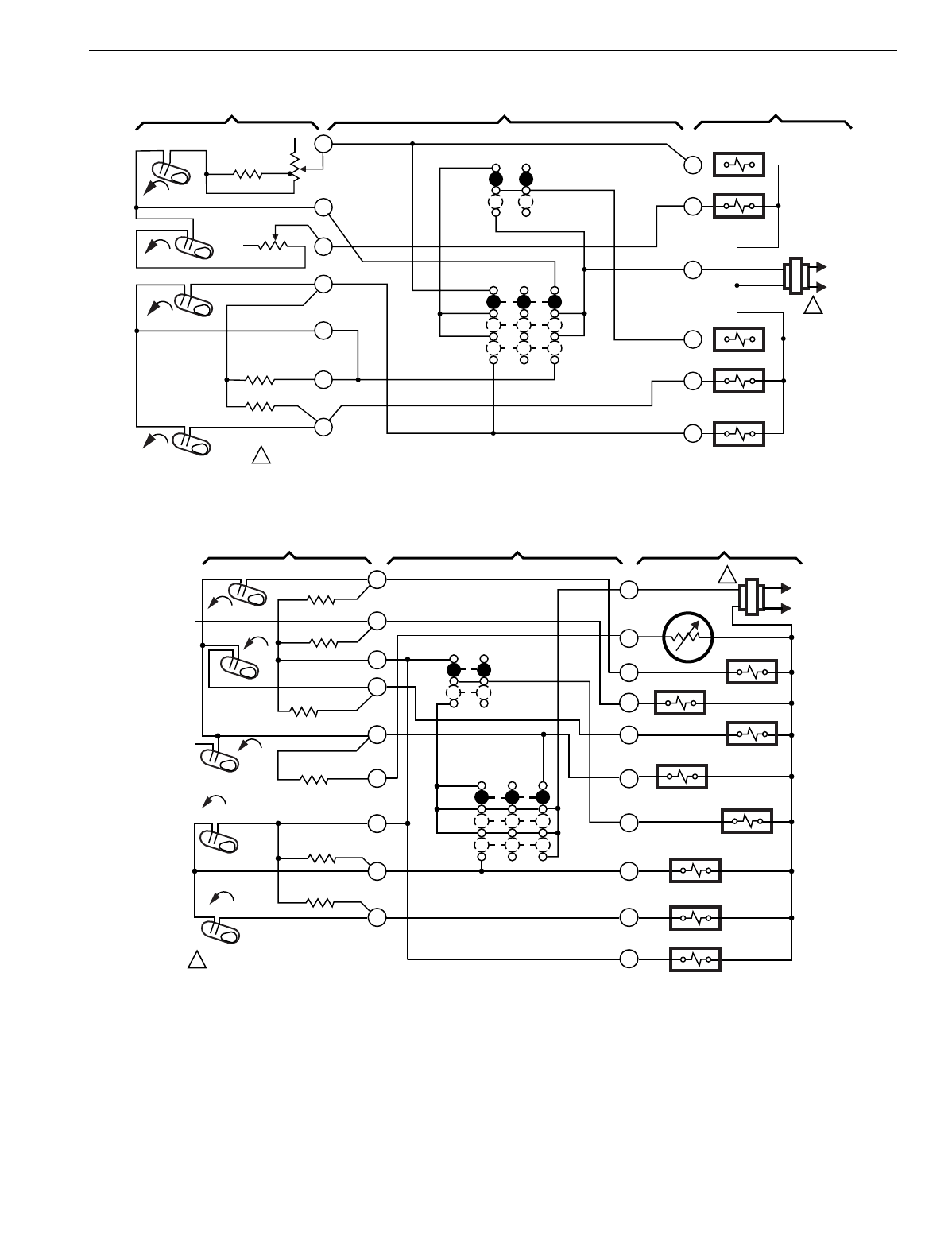
T874 MULTISTAGE THERMOSTATS AND Q674 SUBBASES
101 60-2485—8
Fig. 53. Schematic and hookup of T874D with Q674B. Used in standard applications.
Fig. 54. Schematic and hookup of T874W with Q674B. Used in standard applications.
H1
FALL
W1
W2
G
Y2
Y1
HEAT RELAY 2
HEAT RELAY 1
H1
ANTICIPATOR
C1 ANTICIPATOR
AUTO
ON
FAN SWITCH
1POWER SUPPLY. PROVIDE DISCONNECT MEANS AND OVERLOAD
PROTECTION AS REQUIRED. M3202A
L1
(HOT)
L2
1
FAN RELAY
COMPRESSOR
CONTACTOR 2
COMPRESSOR
CONTACTOR 1
1
4
6
8
9
10
11
H2
FALL
C2 ANTICIPATOR
RISE
RISE
C1
C2
THERMOSTAT SUBBASE SYSTEM COMPONENTS
H2 ANTICIPATOR
R
SYSTEM
SWITCH
HEAT
OFF
COOL
L1 (HOT)
L2
1
W1
T
W2
HEAT RELAY 3
FAN RELAY
W3
HEAT CHANGEOVER VALVE
COMPRESSOR CONTACTOR 2
B
Y2
Y1
SYSTEM
SWITCH
HEAT
OFF
COOL
H1 ANTICIPATOR
C1
H1
FALL
H3
1POWER SUPPLY. PROVIDE DISCONNECT
MEANS AND OVERLOAD PROTECTION
AS REQUIRED. M3674
AUTO
ON
FAN SWITCH
FALL
R
COMPRESSOR CONTACTOR 1
HEAT RELAY 2
HEAT RELAY 1
G
C815A THERMISTOR
H2 ANTICIPATOR
FALL
H3 ANTICIPATOR
H2
C2 ANTICIPATOR
C2
RISE
RISE
COOL CHANGEOVER VALVE
O
C1 ANTICIPATOR
RESET HEATER
THERMOSTAT SUBBASE SYSTEM COMPONENTS
1
2
3
4
5
6
8
10
11
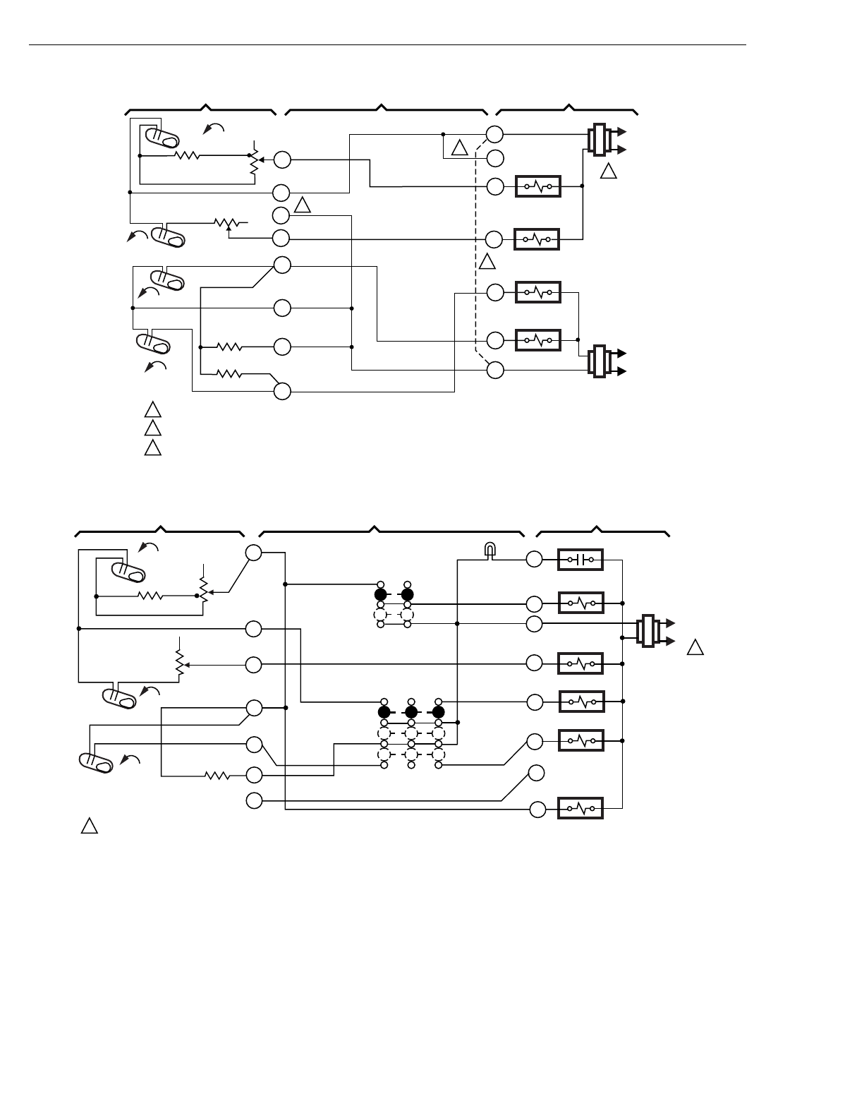
T874 MULTISTAGE THERMOSTATS AND Q674 SUBBASES
60-2485—8102
Fig. 55. Schematic and hookup of T874A,D,F with Q674D. Used in standard applications.
Fig. 56. Schematic and hookup of T874C with Q674B. Used in standard applications.
M3667A
POWER SUPPLY. PROVIDE DISCONNECT MEANS AND OVERLOAD PROTECTION AS REQUIRED.
JUMPER RC, RH FOR SINGLE TRANSFORMER.
B AND 5 TERMINALS AVAILABLE ON SOME MODELS.
COMPRESSOR
CONTACTOR 1
H2 ANTICIPATOR
C1
C1 ANTICIPATOR
C2
H1 ANTICIPATOR
H1
HEAT RELAY 1
HEAT RELAY 2
COMPRESSOR
CONTACTOR 2
FALL L1
(HOT)
L2
RH
W2
Y2
Y1
L1
(HOT)
L2
RC
FALL H2
RISE
C2 ANTICIPATOR
RISE
NO
FAN
SWITCH
NO
SYSTEM
SWITCH
W1
B
1
1
3
2
3
2
1
4
5
6
8
9
10
11
3
THERMOSTAT SUBBASE SYSTEM COMPONENTS
H1
FALL
L1
(HOT)
L2 1
H2 FALL
C1 RISE
FAN
SWITCH
SYSTEM
SWITCH
AUTO
ON
HEAT
OFF
COOL
COMPRESSOR
CONTACTOR 1
O RELAY
B RELAY
AUX. HT. RELAY
FAN RELAY
RESET
RESET
LED (RED)
C1 ANTICIPATOR
H2 ANTICIPATOR
H1 ANTICIPATOR
POWER SUPPLY. PROVIDE DISCONNECT MEANS AND OVERLOAD PROTECTION AS REQUIRED.
1
4
6
8
9
10
11 Y1
Y2
O
B
W2
R
G
X
1
SUBBASE SYSTEM COMPONENTS
M5975
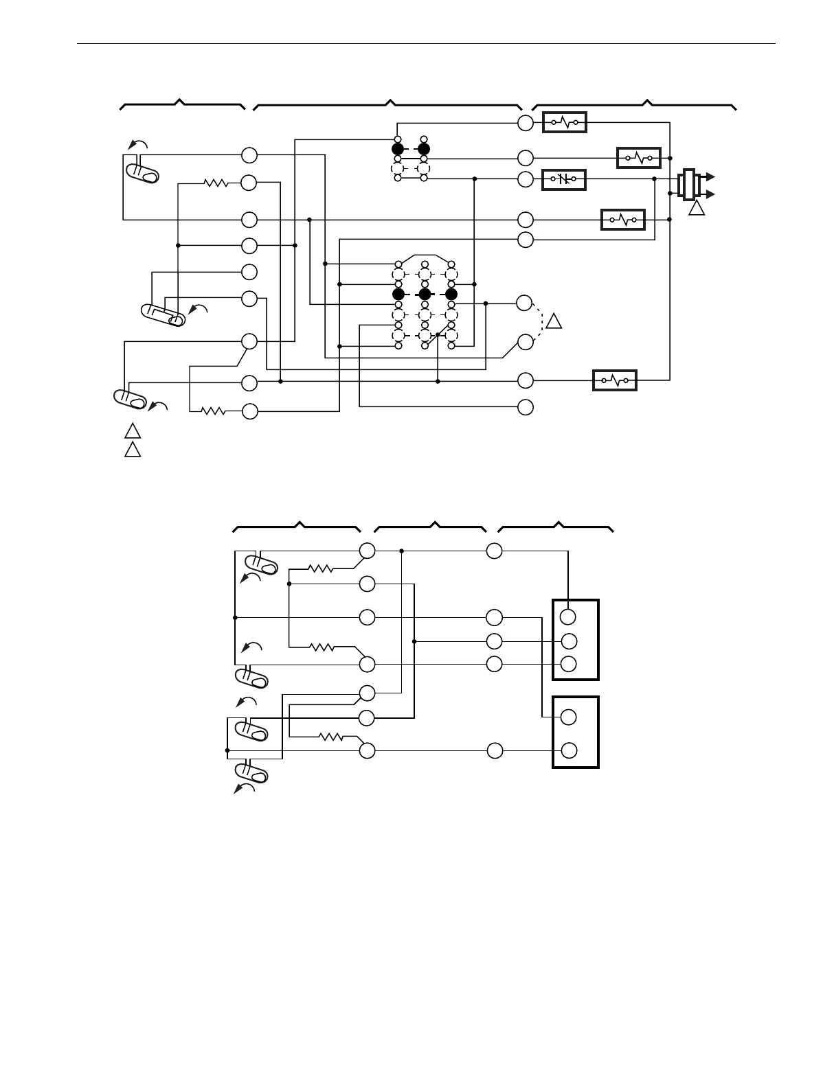
T874 MULTISTAGE THERMOSTATS AND Q674 SUBBASES
103 60-2485—8
Fig. 57. Schematic and hookup of T874P with Q674B. Used in heat pump applications.
Fig. 58. Schematic and hookup of T874G with Q674D. Used in standard applications.
H2
FALL
H1
RISE
CO
L1
(HOT)
L2
1
C1
RISE
2
1
2
POWERSUPPLY. PROVIDE DISCONNECT MEANS AND OVERLOAD PROTECTION AS REQUIRED.
JUMPER HONEYWELL SUPPLIED, FIELD INSTALLED.
C1 ANTICIPATOR
H1 ANTICIPATOR
FAN SWITCH
AUTO
ON
SYSTEM
SWITCH
OVERRIDE
HEAT
OFF
COOL
1
2
3
4
5
6
8
9
10 T
W
P
S
L
B
R
G
Y
COMPRESSOR
CONTACTOR FAN RELAY
CLOSED-DAY
OPEN-NITE B RELAY
JUMPER
COOL CHANGEOVER
VALVE
M8004
THERMOSTAT SUBBASE SYSTEM COMPONENTS
H1 ANTICIPATOR
H1
FALL
M3722
C1
H2 ANTICIPATOR
H2
FALL
ECONOMIZER
PACKAGE
RISE
RISE
CO
C1 ANTICIPATOR
CONTROL
PANEL
W
RH
B
RC
Y
O
O
W2
O
Y
THERMOSTAT SUBBASE SYSTEM COMPONENTS
2
3
4
6
8
9
10
NO FAN
SWITCH
NO SYSTEM
SWITCH
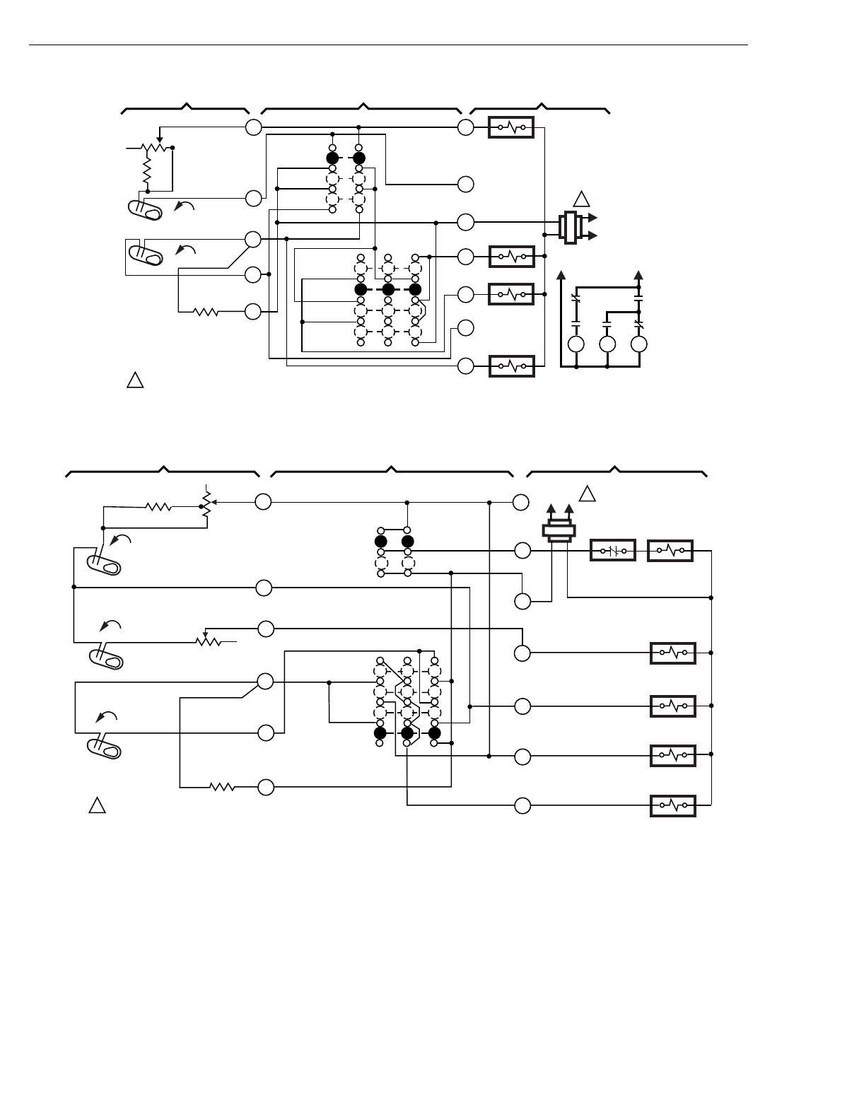
T874 MULTISTAGE THERMOSTATS AND Q674 SUBBASES
60-2485—8104
Fig. 59. Schematic and hookup of T874A with Q674Q. Used in fan coil applications.
Fig. 60. Schematic and hookup of T874C with Q674N. Used in evaporative cooler applications.
L1
(HOT)
L2
1
K2 RELAY
SYSTEM
SWITCH
ON
HIGH
H1
ANTICIPATOR
H1 FALL
1POWER SUPPLY. PROVIDE DISCONNECT MEANS
AND OVERLOAD PROTECTION AS REQUIRED.
M3729
HEAT
COOL
FAN
SWITCH
R
COMPRESSOR
CONTACTOR
Y1
B
O
G1
MED G2
K1 RELAY
W1
C1
ANTICIPATOR
C1 RISE
HEAT
RELAY 1
OFF
K2
K1
K2
K1
K2
HI LOMED
3 SPEED FAN
SCHEMATIC
LO L2 L1
THERMOSTAT SUBBASE SYSTEM COMPONENTS
1
4
8
9
10
L1
(HOT) L2 1
H2 ANTICIPATOR
M2863
H1 ANTICIPATOR
C1 ANTICIPATOR
FALL
H1
R
W2
W1
G
ELEC. HT. RELAY
FAN RELAY
COOL RELAY
CONTACT
1POWER SUPPLY. PROVIDE DISCONNECT MEANS AND OVERLOAD
PROTECTION AS REQUIRED.
AUTO
ON
FAN
SWITCH
SYSTEM
SWITCH
EVAP
HEAT
OFF
COOL
CHANGEOVER
VALVE
COMPRESSOR
CONTACTOR
EVAPORATOR
RELAY
RISE
C1
FALL
H2
Y1
B
Y2
THERMOSTAT SUBBASE SYSTEM COMPONENTS
1
4
6
8
9
10
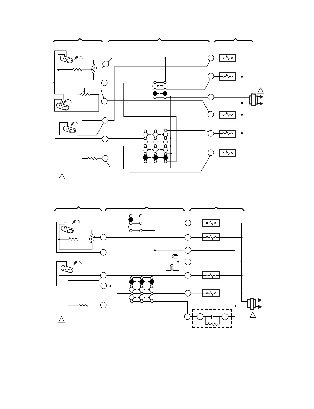
T874 MULTISTAGE THERMOSTATS AND Q674 SUBBASES
105 60-2485—8
Fig. 61. Schematic and hookup of T874C with Q674N. Used in evaporative cooler applications.
Fig. 62. Schematic and hookup of T874F with Q674B. Used in wood/coal applications.
L1
(HOT)
L2
EVAPORATOR
RELAY
ELEC. HT. RELAY
FAN RELAY
COMPRESSOR
CONTACTOR
CHANGEOVER
RELAY
O
Y2
W2
G
R
H2
ANTICIPATOR
AUTO
ON
FAN
SWITCH
H1 ANTICIPATOR
C1
RISE
FALL
H2
FALL
H1
SYSTEM
SWITCH
EVAP.
HEAT
COOL
OFF
1POWER SUPPLY. PROVIDE DISCONNECT MEANS AND OVERLOAD PROTECTION AS REQUIRED.
C1
ANTICIPATOR
Y1
M2862
1
THERMOSTAT SUBBASE SYSTEM COMPONENTS
1
4
6
8
9
10
L1
(HOT)
L2
1
FAN RELAY
SYSTEM
SWITCH
OFF
H2 ANTICIPATOR
H1
H2
FALL
1POWER SUPPLY. PROVIDE DISCONNECT MEANS
AND OVERLOAD PROTECTION AS REQUIRED. M3723A
AUTO
ON
FAN SWITCH
R
COMPRESSOR
CONTACTOR
G
W2
H1 ANTICIPATOR
X2
AUX. HT. RELAY
HEAT
X1
EXTERNAL COOLING
THERMOSTAT
(SUCH AS T87 F)
COOL
W1
R
Y
CWOOD/COAL
RELAY
FALL
YELLOW
GREEN
THERMOSTAT SUBBASE SYSTEM COMPONENTS
1
4
8
9
10
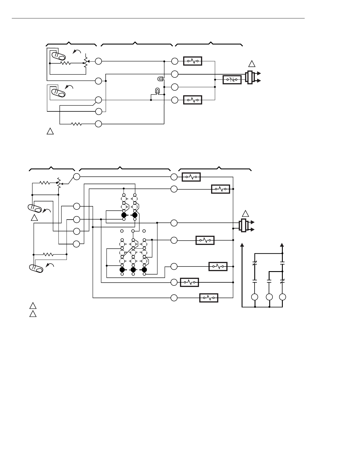
T874 MULTISTAGE THERMOSTATS AND Q674 SUBBASES
60-2485—8106
Fig. 63. Schematic and hookup of T874F with Q674D. Used in wood/coal applications.
Fig. 64. Schematic and hookup of T874A with Q674Q. Used in fan coil applications.
L1
(HOT)
L2
1
NO
SYSTEM
SWITCH
H2 ANTICIPATOR
H1
H2 FALL
1POWER SUPPLY. PROVIDE DISCONNECT MEANS AND OVERLOAD PROTECTION AS REQUIRED.
M3725
NO FAN
SWITCH
R
W2
H1 ANTICIPATOR
AUX. HT. RELAY
W1
C
WOOD/COAL
RELAY
FALL
YELLOW
GREEN
1
4
8
9
10
THERMOSTAT SUBBASE SYSTEM COMPONENTS
HEAT/COOL
SWITCH
H1
FALL
L1
(HOT)
L2
1
C1 RISE
M8005
2
1
2
H1
ANTICIPATOR
C1
ANTICIPATOR
5
4
2
1W1
B
R
G1
G2
O
Y1 HI
MED
LO
K2
K1
K2 K2
K1
COMPRESSOR CONTACTOR
O RELAY
K2 RELAY
K1 RELAY
B RELAY
HEAT RELAY 1
SYSTEM
SWITCHHEAT
OFF
COOL
FAN
SWITCH
LO
MED
HIGH
ON
POWER SUPPLY. PROVIDE DISCONNECT MEANS AND OVERLOAD PROTECTION AS REQUIRED.
SINGLE SETPOINT LEVER AND BIMETAL.
3
L2 L1
THERMOSTAT SUBBASE SYSTEM COMPONENT
3-SPEED FAN SCHEMATIC
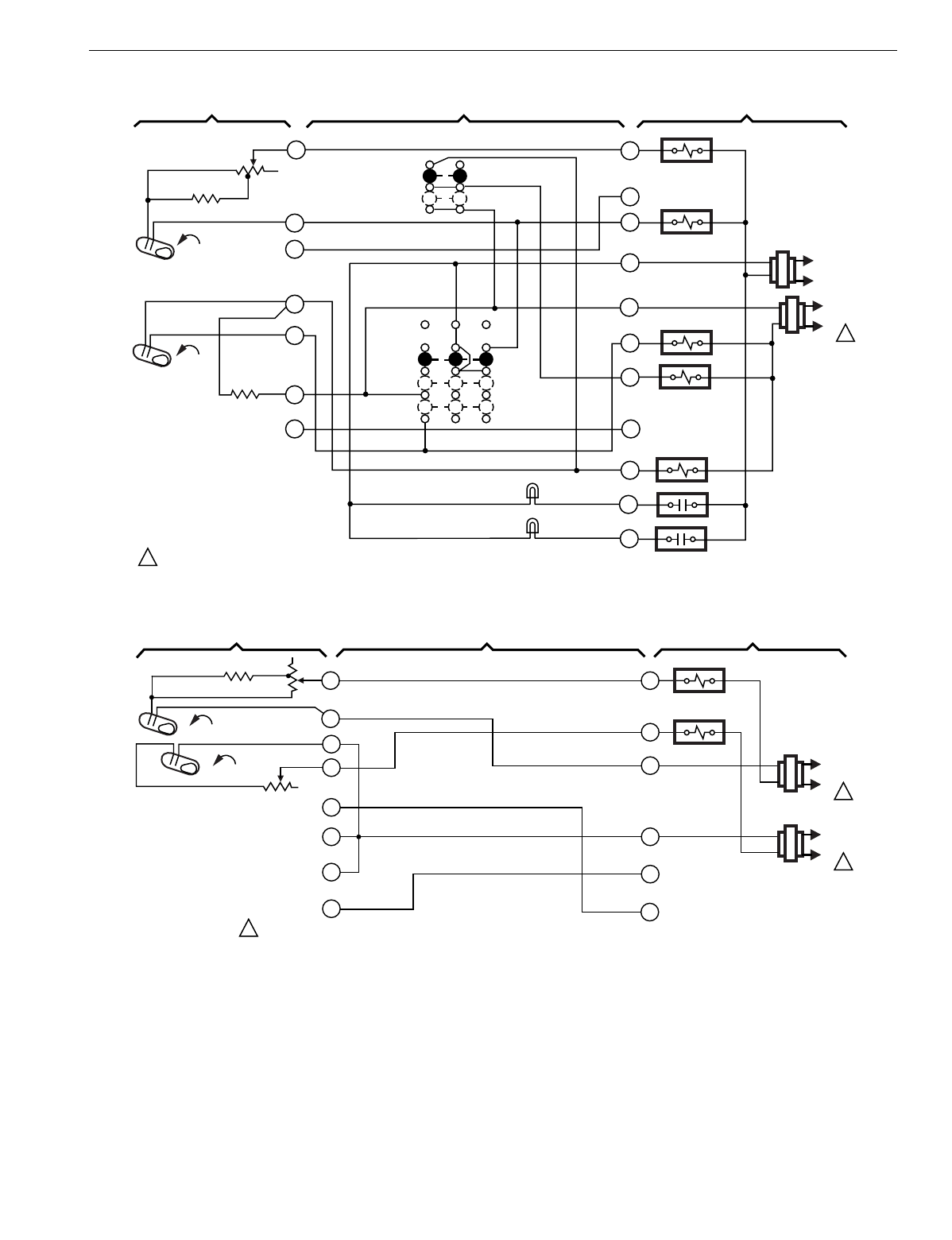
T874 MULTISTAGE THERMOSTATS AND Q674 SUBBASES
107 60-2485—8
Fig. 65. Schematic and hookup of T874A with Q674B. Used in standard applications.
Fig. 66. Schematic and hookup of T874A,D,F with Q674D. Used in standard applications.
C1 RISE
L1
(HOT)
L2 1
L1
(HOT)
L2
1
H1
FALL
POWER SUPPLY. PROVIDE DISCONNECT MEANS AND OVERLOAD PROTECTION AS REQUIRED. M5976
C1
ANTICIPATOR
H1 ANTICIPATOR
SYSTEM
SWITCH
HEAT
OFF
COOL
FAN
SWITCH
AUTO
ON
NO. 1 HEAT RELAY
HEAT DAMPER
COOL DAMPER
FAN RELAY
NO. 1 COMP. RELAY
FILTER
LED (RED)
SERVICE LED
(YELLOW)
X2
X1
Y1
Y2
G
RC
RH
B
W2
W1
1
4
6
8
9
10
11
O
THERMOSTAT SUBBASE SYSTEM COMPONENTS
W2
W1
M7011
THERMOSTAT SUBBASE SYSTEM COMPONENTS
Y2
RH
RC
Y1
H1 ANTICIPATOR
H2 ANTICIPATOR
H1 FALL
FALL
H2
1
4
5
6
8
9
10
11
NO FAN
SWITCH
NO SYSTEM
SWITCH
L1
(HOT)
L2 1
L1
(HOT)
L2 1
HEAT RELAY 1
HEAT RELAY 2
1POWER SUPPLY. PROVIDE DISCONNECT MEANS AND OVERLOAD
PROTECTION AS REQUIRED.
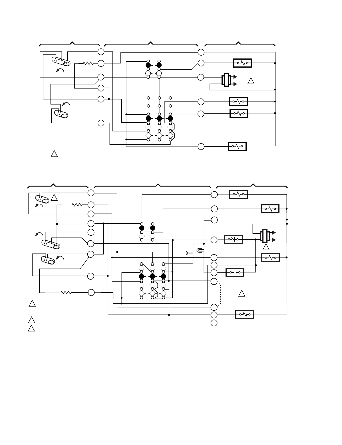
T874 MULTISTAGE THERMOSTATS AND Q674 SUBBASES
60-2485—8108
Fig. 67. Schematic and hookup of T874R with Q674B. Used in heat pump applications.
Fig. 68. Schematic and hookup of T874P with Q674B. Used in heat pump applications.
M5998
H2
FALL
H1
FALL
C1
L1
(HOT)
L2 1
1POWER SUPPLY. PROVIDE DISCONNECT MEANS AND OVERLOAD PROTECTION AS REQUIRED.
THERMOSTAT SUBBASE SYSTEM COMPONENTS
H1/C1 ANTICIPATOR
FAN SWITCH
AUTO
ON
SYSTEM
SWITCH
HEAT
OFF
COOL COMPRESSOR
CONTACTOR
AUX. HT. RELAY
HEAT CHANGEOVER
VALVE
FAN RELAY
6
5
4
3
2
1X
G
R
B
W2
Y
H2
FALL
H1
RISE
CO L1
(HOT)
L2
1
C1
RISE
COMPRESSOR CONTACTOR
FAN RELAY
CLOSED-DAY
OPEN-NITE
B RELAY
SERVICE
LED (RED)
OVERRIDE
LED (RED)
FAN
SWITCH
AUTO
ON
H1
ANTICIPATOR
SYSTEM SWITCH
JUMPER
COOL CHANGEOVER VALVE
OVERRIDE
HEAT
OFF
C1 ANTICIPATOR
1
2
3
4
5
6
8
9
10
W
P
S
X
L
B
R
C
G
Y
POWER SUPPLY. PROVIDE DISCONNECT
MEANS AND OVERLOAD PROTECTION
AS REQUIRED.
JUMPER HONEYWELL SUPPLIED, FIELD INSTALLED.
H2 MAKE OFFEST 8˚ F BELOW H1 MAKE.
3
2
1
2
3M101A
THERMOSTAT SUBBASE SYSTEM COMPONENTS
T
COOL
COMPRESSOR
FAULT
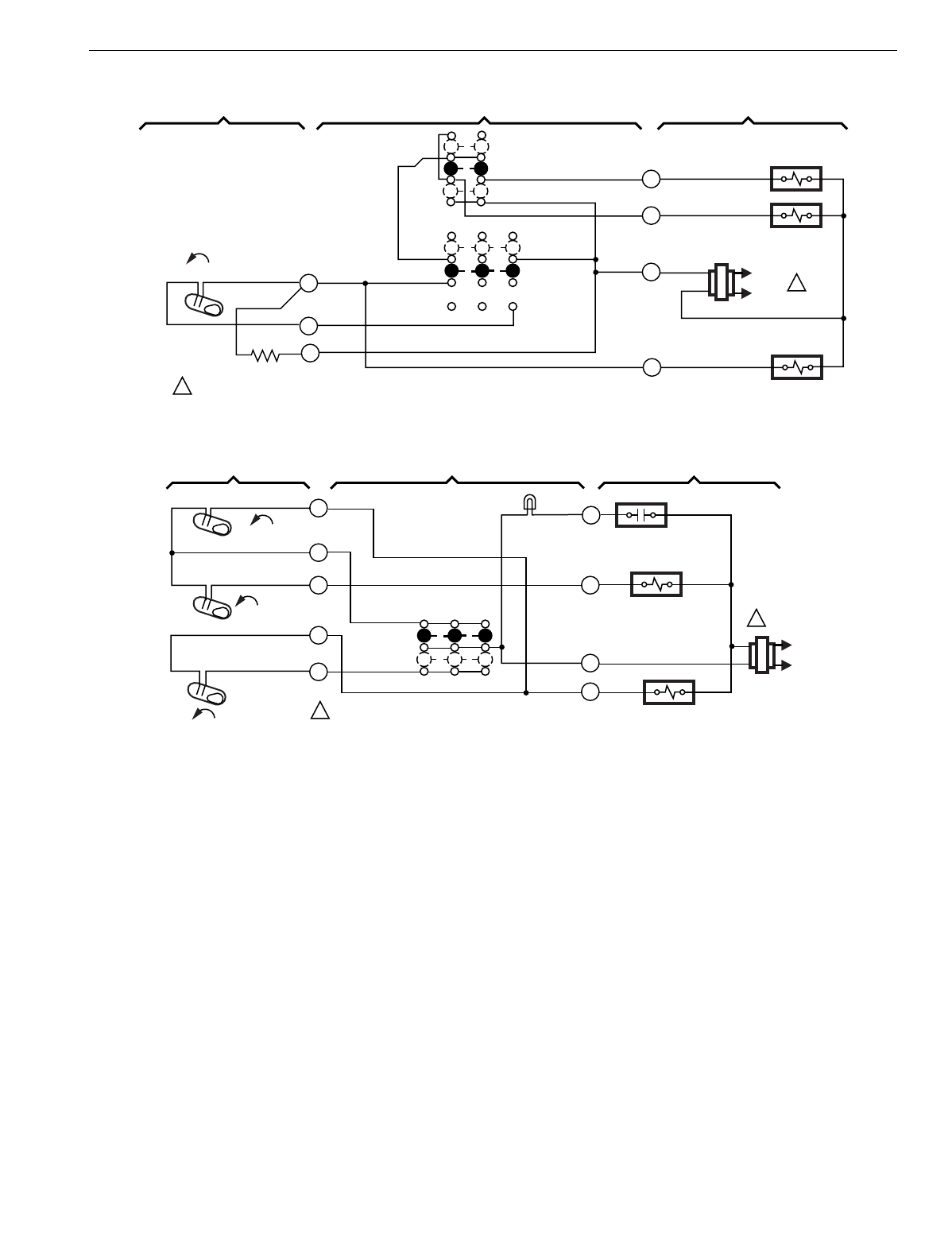
T874 MULTISTAGE THERMOSTATS AND Q674 SUBBASES
109 60-2485—8
Fig. 69. Schematic and hookup of T874V with Q674R. Used in fan coil applications.
Fig. 70. Schematic and hookup of T874C with Q674S. Used in heat pump applications.
C1
RISE L1
(HOT)
L2 1
M107A
FAN SWITCH
LO
AUTO HI
CONT.
SYSTEM SWITCH
OFF
COOL
C1 ANTICIPATOR
POWER SUPPLY. PROVIDE DISCONNECT MEANS AND OVERLOAD PROTECTION AS REQUIRED.
COOL RELAY
FAN RELAY
Z RELAY
8
9
10
Y
R
G
Z
1
THERMOSTAT SUBBASE SYSTEM COMPONENTS
H1 FALL
L1
(HOT)
L2
1
H2 FALL
H1
FALL
1
4
6
8
9
S
W2
R
Y
NO FAN
SWITCH
SYSTEM
SWITCH
HEAT
COOL
THERMOSTAT SUBBASE SYSTEM COMPONENTS
SERVICE
LED (RED)
AUX. HT. RELAY
COMPRESSOR
CONTACTOR
M1402A
POWER SUPPLY. PROVIDE DISCONNECT
MEANS AND OVERLOAD PROTECTION AS REQUIRED.
1
COMPRESSOR
FAULT
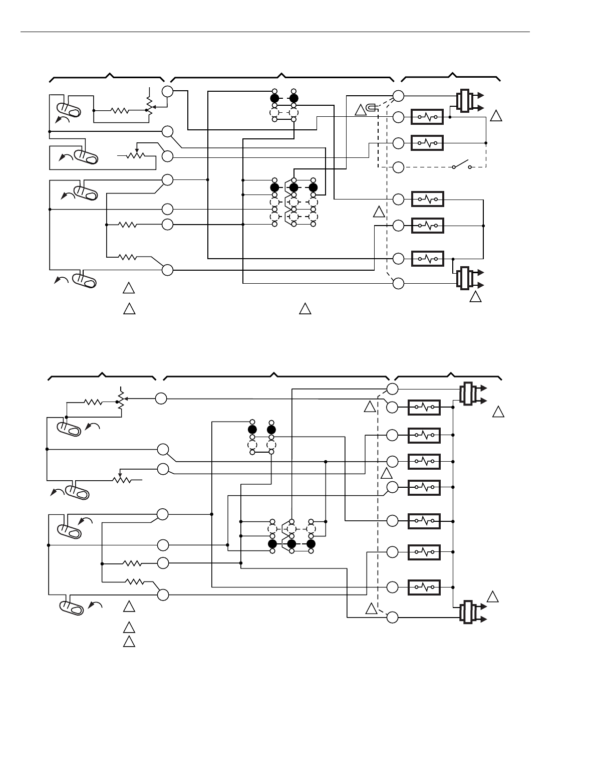
T874 MULTISTAGE THERMOSTATS AND Q674 SUBBASES
60-2485—8110
Fig. 71. Schematic and hookup of T874A-D with Q674A. Used in standard applications.
Fig. 72. Schematic and hookup of T874D,E,F with Q674C. Used in standard applications.
H1
FALL
L1
(HOT)
L2
1
RH
W1
W2
G
Y2
Y1
RC
HEAT RELAY 2
HEAT RELAY 1
HEAT
AUTO
COOL
SYSTEM
SWITCH
H1
ANTICIPATOR
C1 ANTICIPATOR
AUTO
ON
FAN SWITCH
2
1POWER SUPPLY. PROVIDE DISCONNECT MEANS AND OVERLOAD
PROTECTION AS REQUIRED.
JUMPER RH, RC FOR SINGLE TRANSFORMER.
2
M932B
L1
(HOT)
L2
1
FAN RELAY
COMPRESSOR
CONTACTOR 2
COMPRESSOR
CONTACTOR 1
1
4
6
8
9
10
11
H2
FALL
C2 ANTICIPATOR
RISE
RISE
C1
C2
X1
3OPTIONAL LED ON SOME MODELS.
THERMOSTAT SUBBASE SYSTEM COMPONENTS
3
H2 ANTICIPATOR
CHECK
L1
(HOT)
L2
1
H2 ANTICIPATOR
H1 ANTICIPATOR
C1 ANTICIPATOR
C2 ANTICIPATOR
FALL
H1 W2
W1
B
G
RH
1
2
3
3
2
2
POWER SUPPLY. PROVIDE DISCONNECT MEANS AND OVERLOAD
PROTECTION AS REQUIRED.
JUMPER TERMINALS RC-RH FOR SINGLE SYSTEM TRANSFORMER ONLY.
B,O TERMINALS ON SOME MODELS.
AUTO
ON
FAN
SWITCH
SYSTEM
SWITCH
AUTO
OFF
RISE
C2
C1
FALL
RISE
H2
O
Y2
Y1
RC
HEAT DAMPER
COOL DAMPER
FAN RELAY
COMPRESSOR
CONTACTOR 2
COMPRESSOR
CONTACTOR 1
L1
(HOT)
L2
1
HEAT RELAY 1
HEAT RELAY 2
M5122A
THERMOSTAT SUBBASE SYSTEM COMPONENTS
1
4
6
8
9
10
11
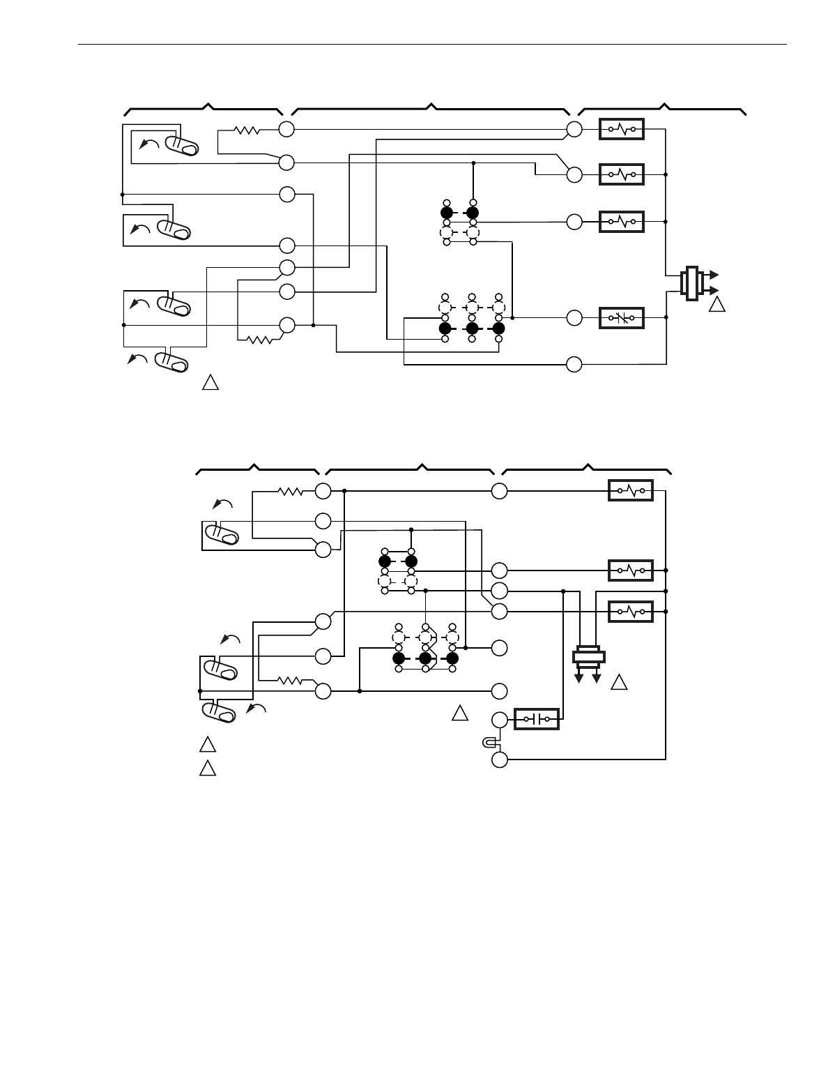
T874 MULTISTAGE THERMOSTATS AND Q674 SUBBASES
111 60-2485—8
Fig. 73. Schematic and hookup of T874G with Q674C. Used in heat pump applications.
Fig. 74. Schematic and hookup of T874H with Q674C. Used in heat pump applications.
H1
FALL
G
Y1
R
FAN RELAY
REVERSING
VALVE RELAY
OFF
AUTO
SYSTEM
SWITCH
H ANTICIPATOR
C ANTICIPATOR
AUTO
ON
FAN SWITCH
1POWER SUPPLY. PROVIDE DISCONNECT MEANS AND OVERLOAD PROTECTION AS REQUIRED. M7008
THERMOSTAT SUBBASE SYSTEM COMPONENTS
Y2
OPEN-NIGHT
CLOSED-DAY
3
4
6
8
10
SETBACK
FALL
RISE
CO L1
(HOT)
L2
1
2
L
COMPRESSOR
CONTACTOR
SETBACK
RELAY
9
RISE
C1
L1
(HOT)
L2 1
FAN RELAY
Y2
SYSTEM
SWITCH
OFF
AUTO
H1
ANTICIPATOR
CO
H1
FALL
1POWER SUPPLY. PROVIDE DISCONNECT MEANS
AND OVERLOAD PROTECTION AS REQUIRED.
SERVICE LED ON SELECT MODELS. M3680A
AUTO
ON
FAN SWITCH
R
COMPRESSOR
CONTACTOR
COOL CHANGEOVER
VALVE
G
C1
RISE
RISE
O
C1
ANTICIPATOR
B
Y1
THERMOSTAT SUBBASE SYSTEM COMPONENTS
2
3
4
8
9
10
SERVICE LED
(YELLOW)
X
C
2
2
COMPRESSOR
FAULT
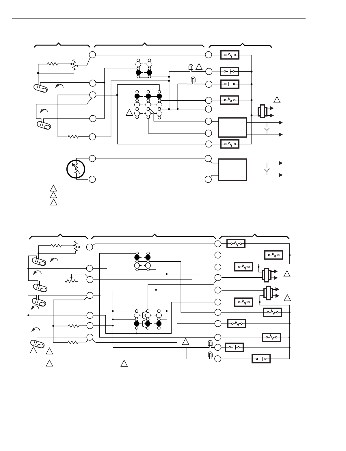
T874 MULTISTAGE THERMOSTATS AND Q674 SUBBASES
60-2485—8112
Fig. 75. Schematic and hookup of T874A with Q674C. Used in standard applications.
Fig. 76. Schematic and hookup of T874A-D with Q674C. Used in standard applications.
C1
RISE
L1
(HOT)
L2
1
3
H1 FALL
2
THERMOSTAT SUBBASE SYSTEM COMPONENTS
SYSTEM SWITCH
OFF
AUTO
FAN SWITCH
AUTO
ON
HEAT RELAY
FILTER LED
(YELLOW)
SERVICE
LED (RED) FAN RELAY
W1
X
A
G
R
O
O
Y
T
T
12
11
10
9
8
4
1
H1
ANTICIPATOR
THERMISTOR
C1
ANTICIPATOR
EXTERNAL
TEMP.
READOUT
COMPRESSOR CONTACTOR
MOMENTARY
CIRCUIT
POWER SUPPLY. PROVIDE DISCONNECT MEANS AND OVERLOAD PROTECTION AS REQUIRED.
MOMENTARY POSITION. SPRING RETURN TO "ON" UPON SWITCH RELEASE.
FILTER LED ON SELECT MODELS.
1
2
3M5731
Y1
RC
1
M7025
THERMOSTAT SUBBASE SYSTEM COMPONENTS
B
Y2
W2
RH
X
H1 ANTICIPATOR
H2 ANTICIPATOR
C1
RISE
H1 FALL
FALL
H2
C2
RISE
C2 ANTICIPATOR
C1 ANTICIPATOR
POWER SUPPLY. PROVIDE DISCONNECT MEANS AND OVERLOAD
PROTECTION AS REQUIRED.
FOR T874C, DELETE C2.
O
A
1
6
9
10
11
4
8
AUTO
ON
FAN
SWITCH
SYSTEM
SWITCH
OFF
HEAT CHANGEOVER
VALVE
HEAT RELAY 1
COMPRESSOR
CONTACTOR 1
HEAT RELAY 2
L1
(HOT)
L2 1
COMPRESSOR
CONTACTOR 2
AUTO
FILTER
LED (YEL)
SERVICE
LED (RED)
W1
G
L1
(HOT)
1
L2
COOL CHANGEOVER
VALVE
FAN RELAY
FILTER LED ON SELECT MODELS.
23
3
2
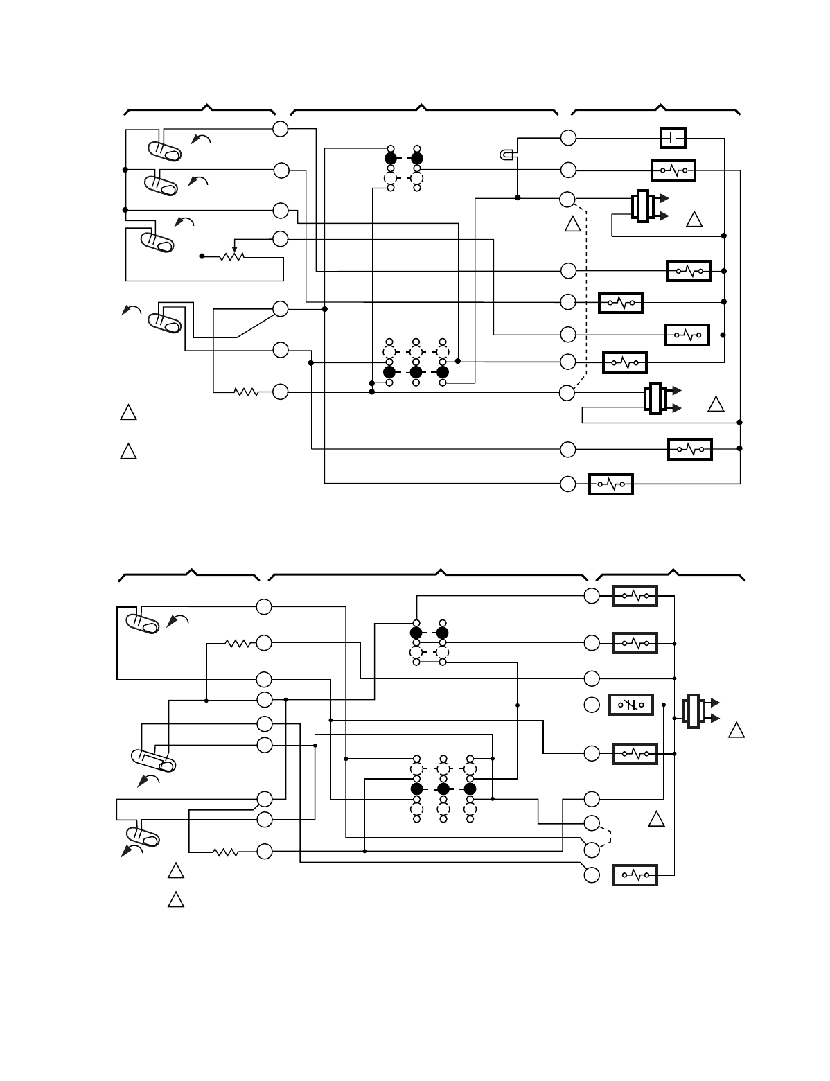
T874 MULTISTAGE THERMOSTATS AND Q674 SUBBASES
113 60-2485—8
Fig. 77. Schematic and hookup of T874K with Q674C. Used in heat pump applications.
Fig. 78. Schematic and hookup of T874P with Q674C. Used in heat pump applications.
C1
RISE
H1
H2
CO
FALL
FALL
FALL
L1
(HOT)
L2 1
1
2
L1
(HOT)
L2 1
2
POWER SUPPLY. PROVIDE DISCONNECT
MEANS AND OVERLOAD PROTECTION
AS REQUIRED.
JUMPER RH AND RC FOR SINGLE
TRANSFORMER SYSTEM.
THERMOSTAT SUBBASE SYSTEM COMPONENTS
H1 ANTICIPATOR
C1
ANTICIPATOR
SYSTEM
SWITCH
FAN
SWITCH
AUTO
ON
OFF
AUTO
FAN RELAY
HEAT CHANGEOVER
VALVE
COMPRESSOR
CONTACTOR
M4729
1
3
4
6
8
9
10
Y1
O
RC
B
W3
W2
W1
RH
G
X1
RESET
LED (RED)
"O" RELAY
"B" RELAY
HEAT RELAY 1
HEAT RELAY 2
B
1
THERMOSTAT SUBBASE SYSTEM COMPONENTS
C
G
R
H1
ANTICIPATOR
C1
RISE
H2 FALL
C1
ANTICIPATOR
POWER SUPPLY. PROVIDE DISCONNECT MEANS AND OVERLOAD
PROTECTION AS REQUIRED.
JUMPER HONEYWELL SUPPLIED, FIELD INSTALLED.
W
1
4
9
10
3
8
AUTO
ON
FAN
SWITCH
SYSTEM
SWITCH
OFF
COMPRESSOR
CONTACTOR
AUTO
Y
L1
(HOT)
1
L2
2
FAN RELAY
SETBACK
CONTACT
M7026
HEAT
CHANGEOVER
VALVE
L
S
P
2
REVERSING
VALVE
JUMPER
2
H1
RISE
CO
5
6
OVERRIDE
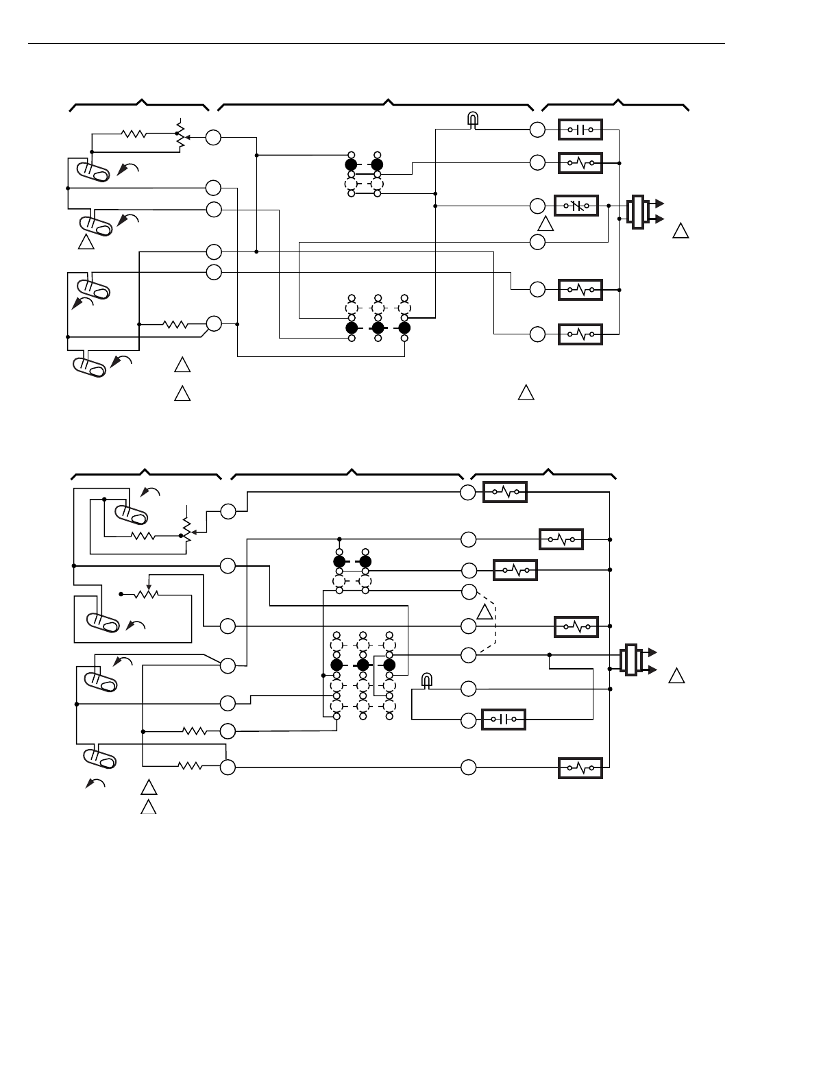
T874 MULTISTAGE THERMOSTATS AND Q674 SUBBASES
60-2485—8114
Fig. 79. Schematic and hookup of T874G,H with Q674C. Used in standard applications.
Fig. 80. Schematic and hookup of T874D with Q674E. Used in standard applications.
O
1
THERMOSTAT SUBBASE SYSTEM COMPONENTS
R1
G
R2
H1 ANTICIPATOR
CO
RISE
H1 FALL
FALL
H2
C1
C1
ANTICIPATOR
POWER SUPPLY. PROVIDE DISCONNECT MEANS AND OVERLOAD
PROTECTION AS REQUIRED.
SETBACK CONTACT ON Q674C1124.
Y
1
6
9
10
4
8
AUTO
ON
FAN
SWITCH
SYSTEM
SWITCH
OFF COMPRESSOR
CONTACTOR
AUTO
X
L1
(HOT)
1
L2
COOL
CHANGEOVER
VALVE
23
RESET
FAN RELAY
SETBACK
CONTACT
RISE
RESET
LED (RED)
H2 ON T874G. M7027
3
2
H1
FALL
FALL
L1
(HOT)
L2 1
2
2
1POWER SUPPLY. PROVIDE DISCONNECT MEANS AND OVERLOAD PROTECTION AS REQUIRED.
OPTIONAL FIELDWIRE JUMPER TO ALLOW SINGLE SYSTEM TRANSFORMER.
THERMOSTAT SUBBASE SYSTEM COMPONENTS
M5997
HEAT
RELAY 1 CONTACTOR
COMPRESSOR 1
FAN RELAY
HEAT RELAY 2
COMPRESSOR
FAULT COMPRESSOR
CONTACTOR 2
SERVICE
LED (RED)
SYSTEM
SWITCH OFF
HEAT
AUTO
COOL
C2 ANTICIPATOR
C1 ANTICIPATOR
C2
RISE
RISE
C1
H2 ANTICIPATOR
H1 ANTICIPATOR
H2
4
6
8
10
11 Y2
Z
C
W2
RC
G
Y1
W1
FAN SWITCH
AUTO
ON
1
RH
9
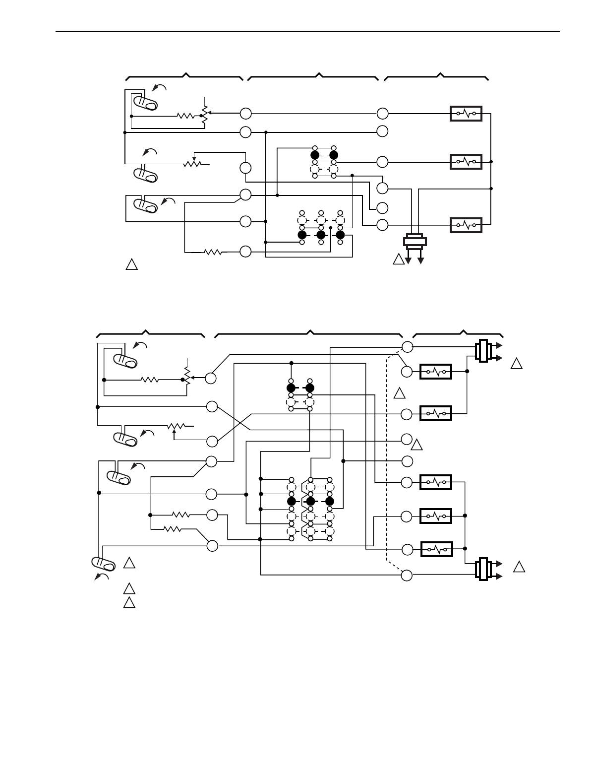
T874 MULTISTAGE THERMOSTATS AND Q674 SUBBASES
115 60-2485—8
Fig. 81. Schematic and hookup of T874C with Q674C. Used in heat pump applications.
Fig. 82. Schematic and hookup of T874A,C,D with Q674E. Used in standard applications.
H1
FALL
L1
(HOT)
L2
1
H2 ANTICIPATOR
OFF
AUTO
FAN
SWITCH
CHANGEOVER
RELAY
M5981
POWER SUPPLY. PROVIDE DISCONECT MEANS
AND OVERLOAD PROTECTION AS REQUIRED.
1
SYSTEM COMPONENTSSUBBASETHERMOSTAT
1
4
6
8
9
10
W1
B
H2
FALL
C1 RISE
G
R
W2
Y1
C1 ANTICIPATOR
AUTO
ON
FAN
RELAY
COMPRESSOR
CONTACTOR
SYSTEM
SWITCH
H1
FALL
H2
FALL
C1
RISE
C2
RISE
L1
(HOT)
L2
L1
(HOT)
L2 1
1
1
2
3
POWER SUPPLY. PROVIDE DISCONNECT
MEANS AND OVERLOAD PROTECTION
AS REQUIRED.
JUMPER RC, RH FOR SINGLE TRANSFORMER.
O AND B TERMINALS ON SELECTED MODELS.
2
3
THERMOSTAT SUBBASE SYSTEM COMPONENTS
H1 ANTICIPATOR
H2 ANTICIPATOR
C2 ANTICIPATOR
C1
ANTICIPATOR
SYSTEM
SWITCH
FAN
SWITCH
AUTO
ON
OFF
HEAT
AUTO
COOL
HEAT RELAY 2
HEAT RELAY 1
COMPRESSOR
CONTACTOR 1
COMPRESSOR
CONTACTOR 2
FAN RELAY
1
4
6
8
9
10
11
RC
Y1
Y2
G
B
O
W2
W1
RH
M934
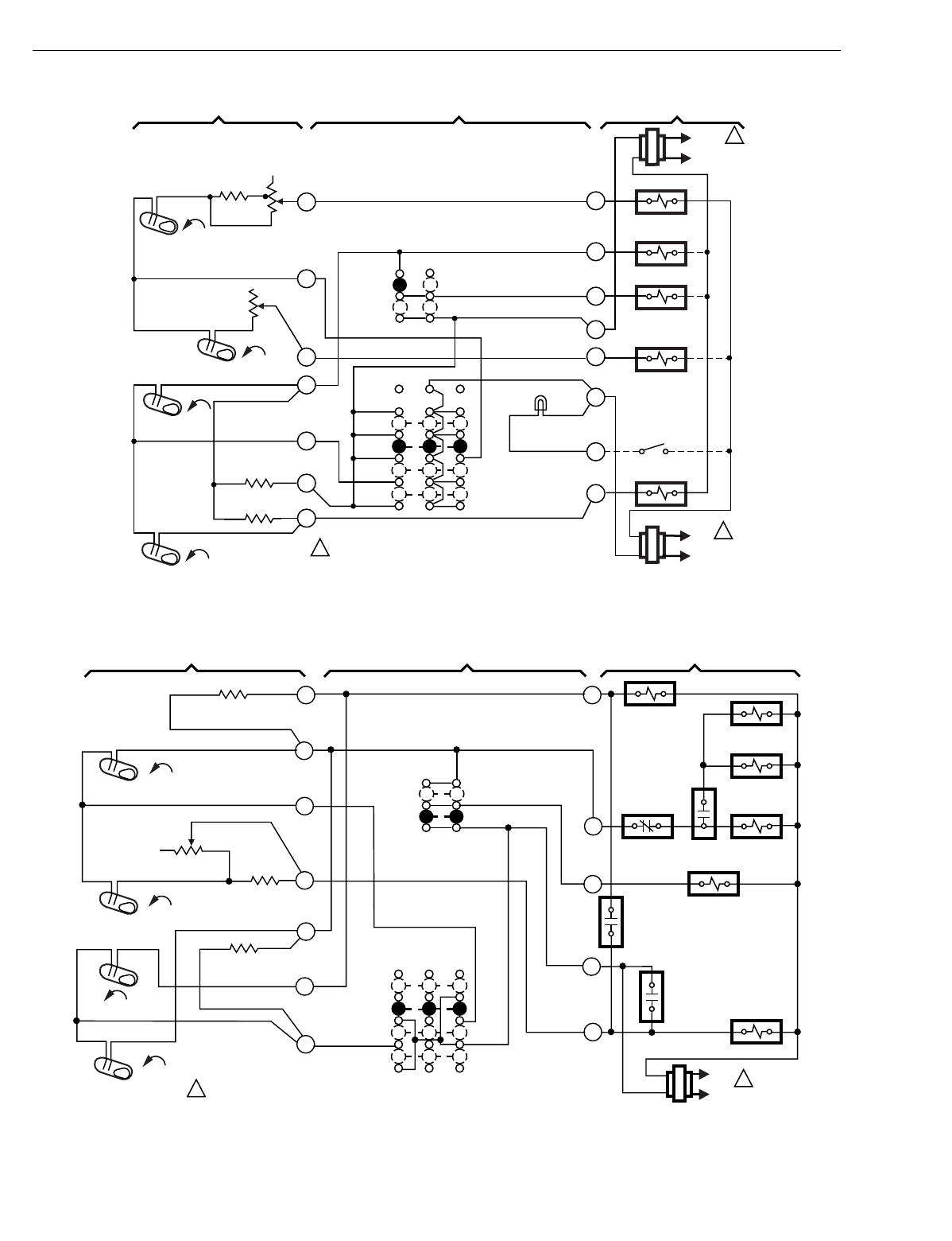
T874 MULTISTAGE THERMOSTATS AND Q674 SUBBASES
60-2485—8116
Fig. 83. Schematic and hookup of T874G with Q674C. Used in standard applications.
Fig. 84. Schematic and hookup of T874G with Q674E. Used in heat pump applications.
H1
FAN
SWITCH
ON
AUTO
CHECK LED
(RED)
M5982
POWER SUPPLY. PROVIDE DISCONECT MEANS
AND OVERLOAD PROTECTION AS REQUIRED.
1
4
6
8
9
10
11
H2 ANTICIPATOR
FALL
H2
RISE
C1
C1 ANTICIPATOR
RISE
C2
FALL
H1 ANTICIPATOR
1
RH
SYSTEM COMPONENTSSUBBASE
THERMOSTAT
L1
(HOT)
L2
1
L1
(HOT)
L2 1
COMPRESSOR
CONTACTOR 1
C2 ANTICIPATOR
AUTO
COOL
HEAT
OFF
X1
RC
W2
G
Y1
W1
HEAT RELAY 1
FAN RELAY
HEAT RELAY 2
COMPRESSOR
CONTACTOR 2
Y2
H1 FALL
H2 FALL
CO
RISE
C1
RISE
L1
(HOT)
L2 1
1POWER SUPPLY. PROVIDE DISCONNECT MEANS AND OVERLOAD
PROTECTION AS REQUIRED.
THERMOSTAT SUBBASE SYSTEM COMPONENTS
H1 ANTICIPATOR
H2 ANTICIPATOR
C1 ANTICIPATOR
SYSTEM
SWITCH
1
2
4
6
8
9
10
Y
V
F
M
R
FAN
SWITCH
AUTO
ON
OFF
HEAT
AUTO
COOL
AUX. HT.
RELAY
DEFROST
RELAY
DEFROST
RELAY
FAN RELAY
HIGH PRESSURE
SWITCH
DEFROST
SWITCH
COOL
CHANGEOVER
VALVE OUTDOOR
FAN RELAY
COMPRESSOR
CONTACTOR
DEFROST
RELAY
M4666
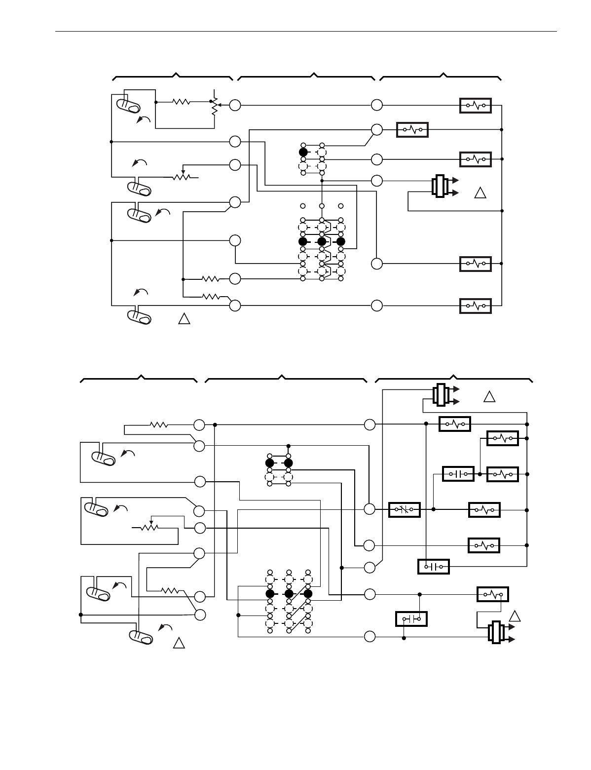
T874 MULTISTAGE THERMOSTATS AND Q674 SUBBASES
117 60-2485—8
Fig. 85. Schematic and hookup of T874A-D with Q674E. Used in standard applications.
Fig. 86. Schematic and hookup of T874G with Q674E. Used in heat pump applications.
H1
FALL
4
H1
ANTICIPATOR
W2
HEAT RELAY 2
L1
(HOT)
L2 1
COMPRESSOR
CONTACTOR 1
M5983
POWER SUPPLY. PROVIDE DISCONECT MEANS AND OVERLOAD PROTECTION AS REQUIRED.
1
SYSTEM COMPONENTSSUBBASETHERMOSTAT
FAN RELAY
H2
RISE
C1
RISE
C2
OFF
SYSTEM
SWITCH
FAN
SWITCH
HEAT
AUTO
COOL
ON
AUTO
R
Y1
W1
Y2
FALL
6
8
10
9
11
1
H2 ANTICIPATOR
C1
ANTICIPATOR
C2 ANTICIPATOR
HEAT RELAY 1
G
COMPRESSOR
CONTACTOR 2
H1
FALL
H2 FALL
CO
RISE
C1 RISE
L1
(HOT)
L2 1
L1
(HOT)
L2
1
1POWER SUPPLY. PROVIDE DISCONNECT MEANS AND
OVERLOAD PROTECTION AS REQUIRED.
THERMOSTAT SUBBASE SYSTEM COMPONENTS
H1 ANTICIPATOR
H2 ANTICIPATOR
C1 ANTICIPATOR
SYSTEM
SWITCH
FAN
SWITCH
AUTO
ON
OFF
HEAT
AUTO
COOL
AUX. HT. RELAY
DEFROST RELAY
CONTACT
COOL
CHANGEOVER
VALVE
COMPRESSOR
CONTACTOR
DEFROST
RELAY
M4667
1
2
3
5
6
8
9
10
VR
Y
V
F
M
R
HIGH
PRESSURE
SWITCH
DEFROST RELAY
CONTACT
FAN RELAY
DEFROST
SWITCH
D. F. O.
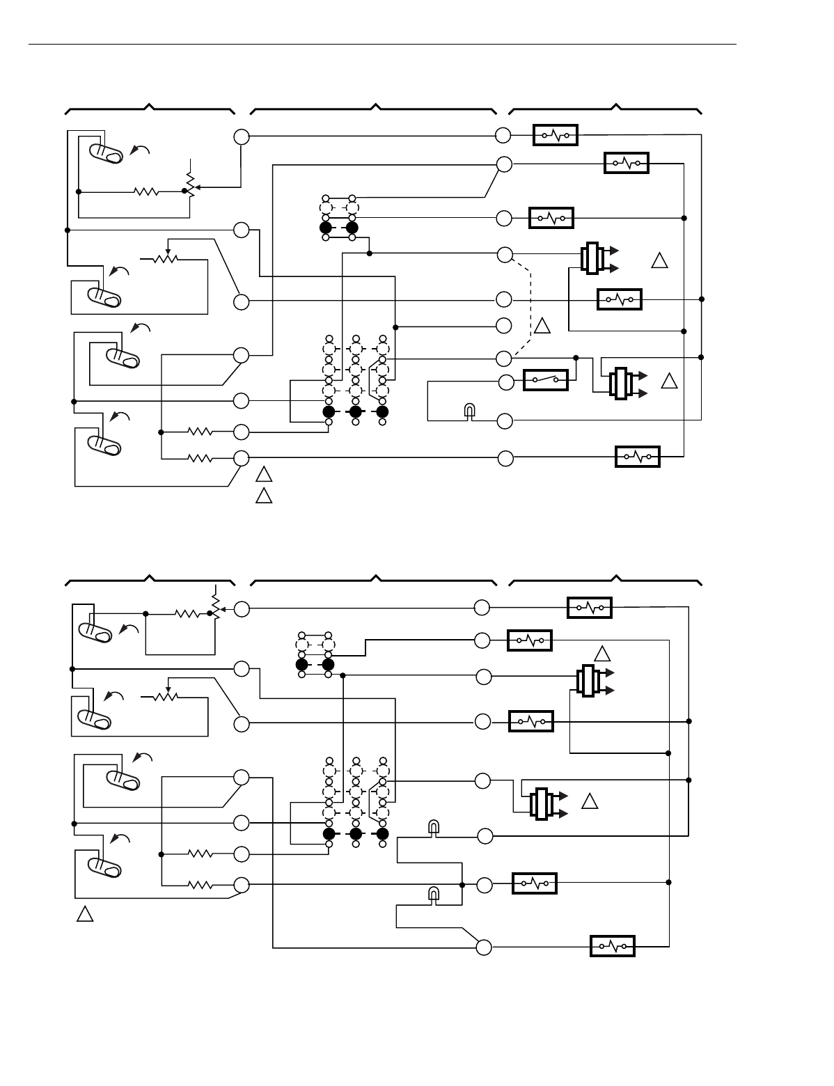
T874 MULTISTAGE THERMOSTATS AND Q674 SUBBASES
60-2485—8118
Fig. 87. Schematic and hookup of T874D with Q674E. Used in standard applications.
Fig. 88. Schematic and hookup of T874B,D with Q674E. Used in standard applications.
C2
RISE
C1
RISE
H2
FALL
H1 FALL
L1
(HOT)
L2 1
L1
(HOT)
L2 1
2
1
2
POWER SUPPLY. PROVIDE DISCONNECT MEANS AND OVERLOAD PROTECTION AS REQUIRED.
FIELDWIRE JUMPER TO ALLOW SINGLE SYSTEM TRANSFORMER.
H1 ANTICIPATOR
H2 ANTICIPATOR
C1 ANTICIPATOR
C2 ANTICIPATOR
SYSTEM
SWITCH
FAN
SWITCH
AUTO
ON
OFF
HEAT
AUTO
COOL
COMPRESSOR
CONTACTOR 1
COMPRESSOR
CONTACTOR 2
M4668
1
SYSTEM
FAULT CONTACT
FAN RELAY
HEAT RELAY 1
HEAT RELAY 2
LOCKOUT LED
(RED)
THERMOSTAT SUBBASE SYSTEM COMPONENTS
W1
Y1
RC
W2
B
G
RH
C
X
Y2
11
10
9
8
6
4
C2
RISE
C1
RISE
H2
FALL
H1 FALL
L1
(HOT)
L2
1
L1
(HOT)
L2 1
1POWER SUPPLY. PROVIDE DISCONNECT
MEANS AND OVERLOAD
PROTECTION AS REQUIRED.
H1
ANTICIPATOR
H2 ANTICIPATOR
C1 ANTICIPATOR
C2 ANTICIPATOR
SYSTEM
SWITCH
FAN
SWITCH
AUTO
ON
OFF
HEAT
AUTO
COOL
COMPRESSOR
CONTACTOR 1
COMPRESSOR
CONTACTOR 2
M4669
1
FAN RELAY
HEAT RELAY 1
HEAT RELAY 2
HIGH LED (RED)
LOW LED (GREEN)
THERMOSTAT SUBBASE SYSTEM COMPONENTS
W1
Y1
RC
W2
G
RH
X
Y2
11
10
9
8
6
4
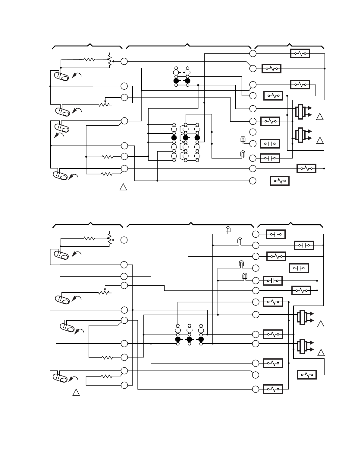
T874 MULTISTAGE THERMOSTATS AND Q674 SUBBASES
119 60-2485—8
Fig. 89. Schematic and hookup of T874D with Q674E. Used in standard applications.
Fig. 90. Schematic and hookup of T874D with Q674G. Used in standard applications.
Y1
W1
RC
1M7023
THERMOSTAT SUBBASE SYSTEM COMPONENTS
B
Y2
G
W2
RH
X
H1 ANTICIPATOR
H2 ANTICIPATOR
C1
RISE
H1 FALL
FALL
H2
C2 RISE C2 ANTICIPATOR
C1 ANTICIPATOR
POWER SUPPLY. PROVIDE DISCONNECT MEANS AND OVERLOAD
PROTECTION AS REQUIRED.
O
A
1
6
9
10
11
4
8
AUTO
ON
FAN
SWITCH
SYSTEM
SWITCH
HEAT
OFF
COOL
HEAT CHANGEOVER
VALVE
HEAT
RELAY 1
COMPRESSOR
CONTACTOR 1
FAN RELAY
HEAT RELAY 2
L1
(HOT)
L2 1
L1
(HOT)
L2 1
COOL CHANGEOVER
VALVE
COMPRESSOR
CONTACTOR 2
AUTO
FILTER
LED (YEL)
SERVICE
LED (RED)
W1
A2
A1
OFF
AUTO
SYSTEM
SWITCH
1M7022
THERMOSTAT SUBBASE SYSTEM COMPONENTS
X2
L1
(HOT)
L2 1
B
X1
W2
T
RC
H1 ANTICIPATOR
H2 ANTICIPATOR
C1 RISE
H1 FALL
FALL
H2
C2 RISE C2 ANTICIPATOR
C1 ANTICIPATOR
POWER SUPPLY. PROVIDE DISCONNECT MEANS AND OVERLOAD
PROTECTION AS REQUIRED.
NO FAN
SWITCH
RH
O
1
6
9
10
11
4
7
Y2
Y1
HEAT RELAY 1
HEAT RELAY 2
T RELAY
HEAT
CHANGEOVER
VALVE
COMPRESSOR
CONTACTOR 2
COMPRESSOR
CONTACTOR 1
L1
(HOT)
L2 1
5
8
12
FILTER LED (YEL)
SERVICE
LED (RED)
FILTER
LED (YEL)
SERVICE
LED (RED)
COOL
CHANGEOVER
VALVE
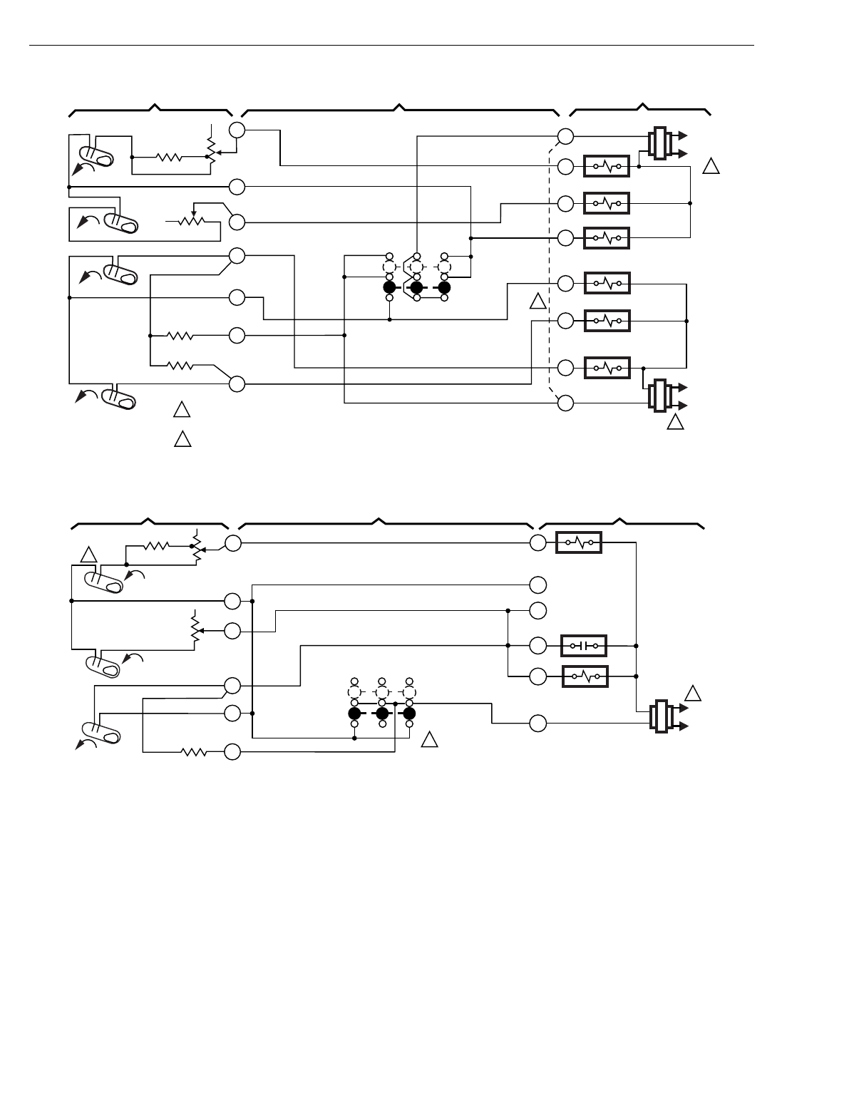
T874 MULTISTAGE THERMOSTATS AND Q674 SUBBASES
60-2485—8120
Fig. 91. Schematic and hookup of T874A-F,Q with Q674G. Used in standard applications.
Fig. 92. Schematic and hookup of T874C with Q674G. Used in heat pump applications.
H1
FALL
L1
(HOT)
L2
1
RH
W1
W2
O
Y2
Y1
RC
HEAT RELAY 2
HEAT RELAY 1
OFF
AUTO
SYSTEM
SWITCH
H1
ANTICIPATOR
C1 ANTICIPATOR
NO FAN
SWITCH
2
1POWER SUPPLY. PROVIDE DISCONNECT MEANS AND OVERLOAD
PROTECTION AS REQUIRED.
JUMPER RH, RC FOR SINGLE TRANSFORMER.
2
M3201B
L1
(HOT)
L2
1
COOL DAMPER
HEAT DAMPER
COMPRESSOR
CONTACTOR 2
COMPRESSOR
CONTACTOR 1
1
4
6
8
9
10
11
H2
FALL
C2 ANTICIPATOR
RISE
RISE
C1
C2
B
THERMOSTAT SUBBASE SYSTEM COMPONENTS
H2 ANTICIPATOR
L2
1
OFF
H1 ANTICIPATOR
H2 ANTICIPATOR
H1
1POWER SUPPLY. PROVIDE DISCONNECT MEANS AND
OVERLOAD PROTECTION AS REQUIRED. M6008A
Y1
W1
C1 ANTICIPATOR
AUTO
FALL
FALL
CHANGEOVER
RELAY
L1
(HOT)
R
FAN RELAY
COMPRESSOR
CONTACTOR
G
3
THERMOSTAT SUBBASE SYSTEM COMPONENTS
NO FAN
SWITCH
SYSTEM
SWITCH
RISE
H2
W2
B
1
4
6
8
9
10
C1
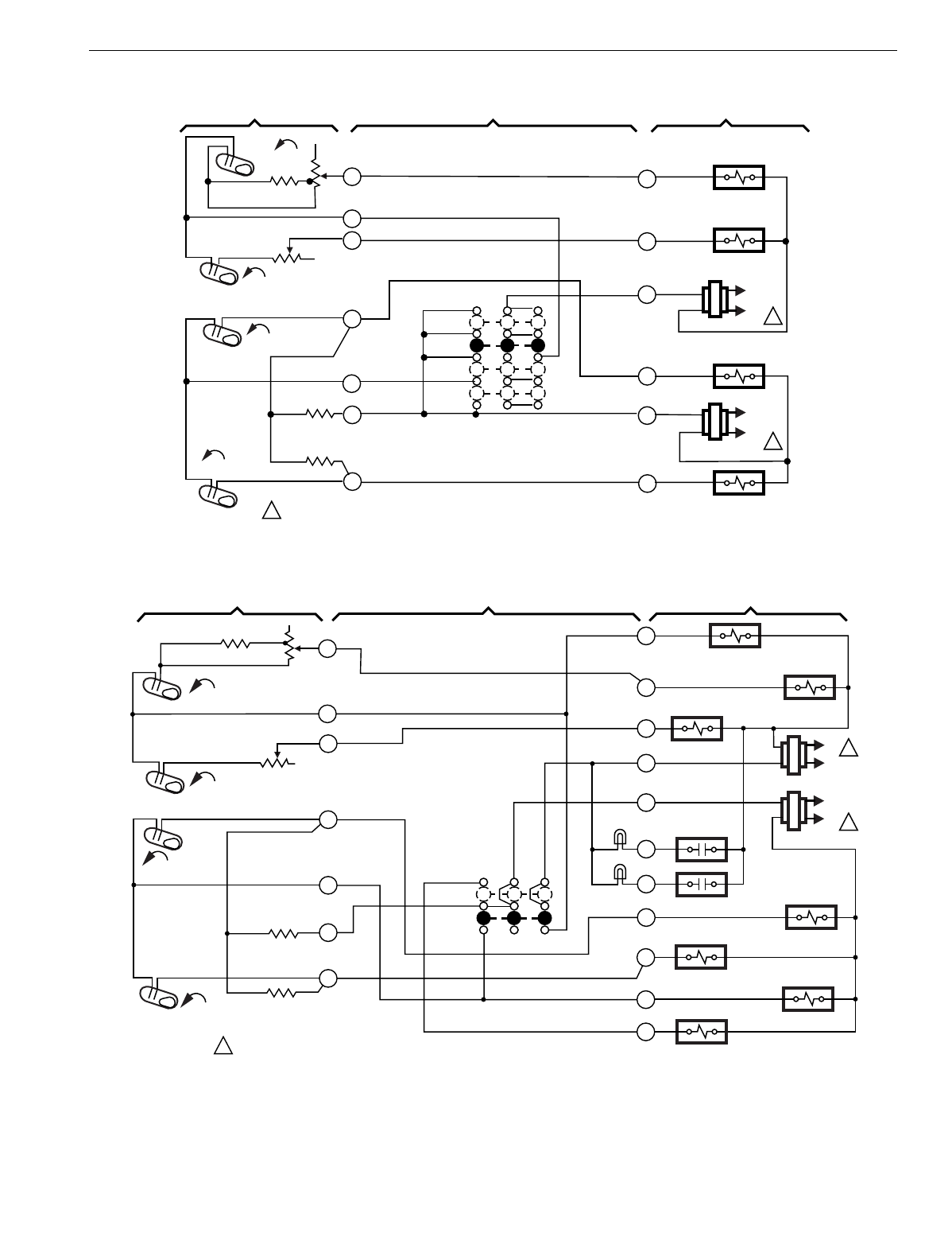
T874 MULTISTAGE THERMOSTATS AND Q674 SUBBASES
121 60-2485—8
Fig. 93. Schematic and hookup of T874D with Q674K. Used in standard applications.
Fig. 94. Schematic and hookup of T874D with Q674G. Used in standard applications.
H1 FALL
H2 FALL
C1
RISE
C2
RISE
L1
(HOT)
L2
L1
(HOT)
L2 1
1
1POWER SUPPLY. PROVIDE DISCONNECT MEANS AND OVERLOAD
PROTECTION AS REQUIRED.
THERMOSTAT SUBBASE SYSTEM COMPONENTS
NO FAN
SWITCH
SYSTEM
SWITCH
11
10
9
8
6
4
1
OFF
HEAT
AUTO
COOL
C2 ANTICIPATOR
C1 ANTICIPATOR
H2
ANTICIPATOR
H1 ANTICIPATOR
HEAT FAN RELAY
HEAT RELAY
COMPRESSOR
CONTACTOR 1
COMPRESSOR
CONTACTOR 2
W1
W2
RH
Y1
RC
Y2
M4664
W2
W1
RC
HEAT CHANGEOVER
VALVE
OFF
AUTO
SYSTEM
SWITCH
1M7013
THERMOSTAT SUBBASE SYSTEM COMPONENTS
B
L1
(HOT)
L2 1
Y2
HEAT
RELAY 2
RH
X
A
Y1
COMPRESSOR
CONTACTOR 1
COMPRESSOR
CONTACTOR 2
L1
(HOT)
L2 1
H1 ANTICIPATOR
H2 ANTICIPATOR
C1
RISE
H1 FALL
FALL
H2
C2 RISE C2 ANTICIPATOR
C1 ANTICIPATOR
POWER SUPPLY. PROVIDE DISCONNECT MEANS AND OVERLOAD
PROTECTION AS REQUIRED.
NO FAN
SWITCH
HEAT
RELAY 1
O
T
COOL CHANGEOVER
VALVE
"T" RELAY
1
6
9
10
11
FILTER
LED (YELLOW)
SERVICE
LED (RED)
4
8
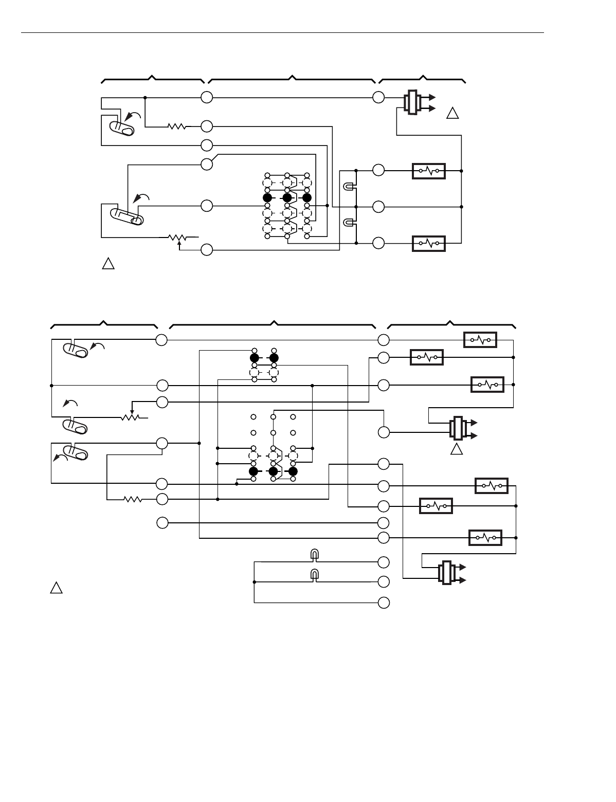
T874 MULTISTAGE THERMOSTATS AND Q674 SUBBASES
60-2485—8122
Fig. 95. Schematic and hookup of T874F with Q674K. Used in wood/oil applications.
Fig. 96. Schematic and hookup of T874C with Q674C. Used in standard applications.
H1
FALL
1
OFF
WOOD
SYSTEM
SWITCH
H1 ANTICIPATOR
WOOD/OIL
OIL
OIL LED
(RED)
W2
M5984
POWER SUPPLY. PROVIDE DISCONECT MEANS AND OVERLOAD PROTECTION AS REQUIRED.
1
SYSTEM COMPONENTSSUBBASETHERMOSTATS
2
3
4
5
6
H2
FALL
NO FAN
SWITCH
OIL RELAY
WOOD RELAY
L1
(HOT)
L2 1
X
W1
R
WOOD LED
(GREEN)
H2 ANTICIPATOR
H2
FALL
L1
(HOT)
L2
1
POWER SUPPLY. PROVIDE DISCONNECT
MEANS AND OVERLOAD PROTECTION AS REQUIRED.
THERMOSTAT SUBBASE SYSTEM COMPONENTS
L1
(HOT)
L2
1
C1
RISE
H1 FALL
FAN SWITCH
AUTO
ON
SYSTEM
SWITCH
OFF
AUTO
C1 ANTICIPATOR
H2 ANTICIPATOR
NO. 1 HEAT RELAY
NO. 2
HEAT RELAY
HEAT
DAMPER
COOL DAMPER
FAN RELAY
NO. 1 COMPRESSOR
CONTACTOR
ON LED
(YELLOW)
SERVICE
LED (RED)
C
A
X
Y1
Y2
G
O
RC
RH
B
W2
W1
1
4
6
8
9
10
11
M104A
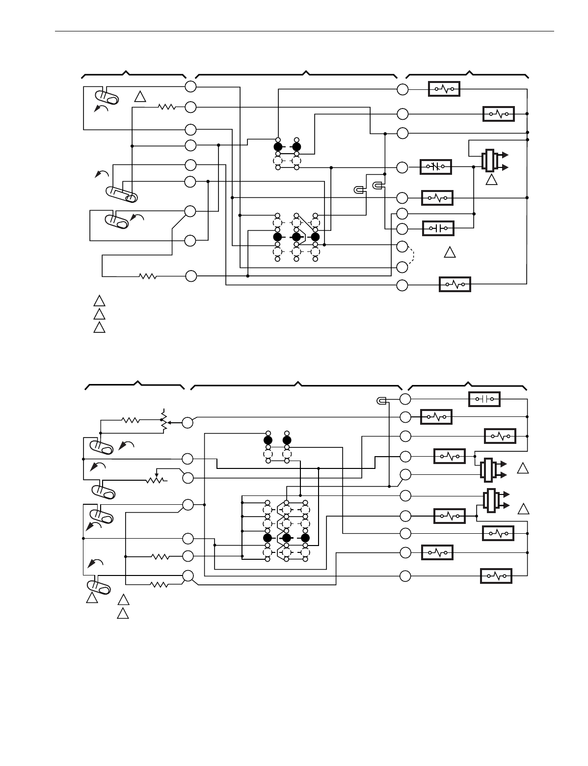
T874 MULTISTAGE THERMOSTATS AND Q674 SUBBASES
123 60-2485—8
Fig. 97. Schematic and hookup of T874P with Q674C. Used in heat pump applications.
Fig. 98. Schematic and hookup of T874D with Q674E. Used in standard applications.
H2
FALL
H1
RISE
CO
L1
(HOT)
L2
1
C1
RISE
COMPRESSOR CONTACTOR
FAN RELAY
CLOSED-DAY
OPEN-NITE
B RELAY
SERVICE
LED (RED)
OVERRIDE
LED (RED)
FAN
SWITCH
AUTO
ON
H1
ANTICIPATOR
SYSTEM SWITCH
JUMPER
COOL CHANGEOVER VALVE
OVERRIDE
AUTO
OFF
C1 ANTICIPATOR
1
2
3
4
5
6
8
9
10
W
P
S
X
L
B
R
C
G
Y
POWER SUPPLY. PROVIDE DISCONNECT MEANS AND OVERLOAD PROTECTION AS REQUIRED.
JUMPER HONEYWELL SUPPLIED, FIELD INSTALLED.
H2 MAKE OFFEST 8˚ F BELOW H1 MAKE.
3
2
1
2
3M100A
THERMOSTAT SUBBASE SYSTEM COMPONENTS
COMPRESSURE FAILURE
Y1
RC
1
M5106A
THERMOSTAT SUBBASE SYSTEM COMPONENTS
B
Y2
W2
RH
H1 ANTICIPATOR
H2 ANTICIPATOR
C1
RISE
H1 FALL
FALL
H2
C2
RISE
C2 ANTICIPATOR
C1 ANTICIPATOR
POWER SUPPLY. PROVIDE DISCONNECT MEANS AND OVERLOAD PROTECTION AS REQUIRED.
T874A IS SINGLE-STAGE (NO W2 OR Y2).
O
A
AUTO
ON
FAN
SWITCH
SYSTEM
SWITCH
OFF
CHANGEOVER
RELAY
HEAT RELAY 1
COMPRESSOR
CONTACTOR 1
HEAT RELAY 2
L1
(HOT)
L2 1
COMPRESSOR
CONTACTOR 2
AUTO
HEAT
SERVICE
LED (RED)
W1
G
L1
(HOT)
1
L2
CHANGEOVER
RELAY
FAN RELAY
2
SYSTEM MONITOR
COOL
1
6
9
10
11
4
8
2
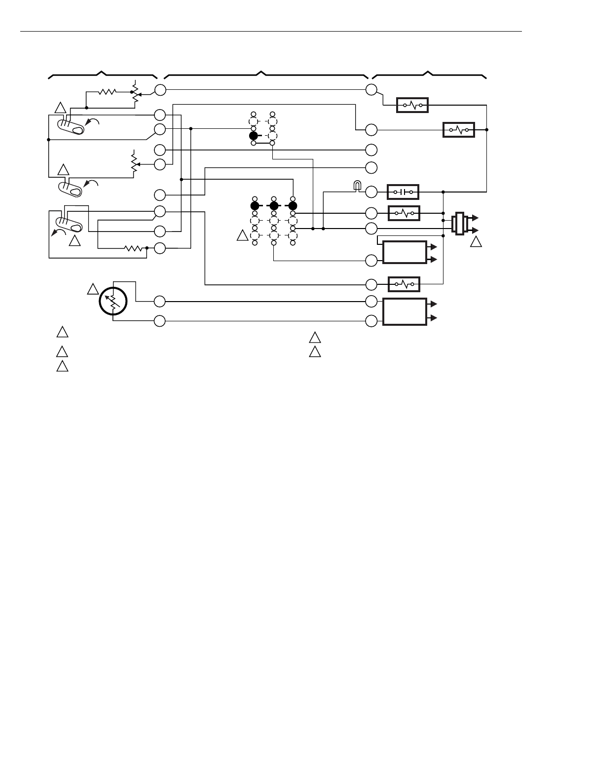
T874 MULTISTAGE THERMOSTATS AND Q674 SUBBASES
60-2485—8124
Fig. 99. Schematic and hookup of T874C with Q674C. Used in standard applications.
L2
1
ON
H1 ANTICIPATOR
H2 ANTICIPATOR
H1
1POWER SUPPLY. PROVIDE DISCONNECT MEANS AND
OVERLOAD PROTECTION AS REQUIRED.
MOMENTARY POSITION. SPRING RETURN TO "ON" UPON SWITCH RELEASE.
H1 AND C1 ARE DPST SWITCHES.
M531
Y1
W1
C1 ANTICIPATOR
AUTO
FALL
FALL
HEAT RELAY 1
HEAT RELAY 2
COMPRESSOR RELAY
L1
(HOT)
RFAN RELAY
O
AUTO
OFF
SERVICE
LED (RED)
A
G
2
2
3
4
5
5
3
3
4
MOMENTARY
CIRCUIT
T
TEXTERNAL
TEMP.
READOUT
THERMOSTAT SUBBASE SYSTEM COMPONENTS
FAN
SWITCH
SYSTEM
SWITCH
RISE
H2
THERMISTER
W2
W3
Y2
1
2
4
5
6
7
8
9
10
C1
11
12
H3 OFFSET 12°F FROM H2 FOR NIGHT SETBACK.
THERMISTOR INTERNAL TO THERMOSTAT.
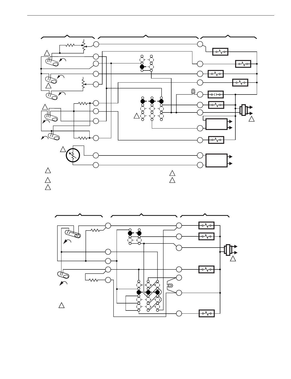
T874 MULTISTAGE THERMOSTATS AND Q674 SUBBASES
125 60-2485—8
Fig. 100. Schematic and hookup of T874W with Q674C. Used in standard applications.
Fig. 101. Schematic and hookup of T874R with Q674L. Used in heat pump applications.
L2
1
ON
H1 ANTICIPATOR
H2 ANTICIPATOR
H1
1POWER SUPPLY. PROVIDE DISCONNECT MEANS AND
OVERLOAD PROTECTION AS REQUIRED.
MOMENTARY POSITION. SPRING RETURN TO "ON" UPON SWITCH RELEASE.
H1 AND C1 ARE DPST SWITCHES.
M532
Y1
W1
C2
ANTICIPATOR
C2 ANTICIPATOR
AUTO
FALL
FALL
FALL
HEAT RELAY 1
HEAT RELAY 2
HEAT RELAY 3
COMPRESSOR RELAY
L1
(HOT)
RFAN RELAY
O
AUTO
OFF
SERVICE
LED (RED)
A
G
2
2
3
4
5
5
3
3
4
MOMENTARY
CIRCUIT
T
TEXTERNAL
TEMP.
READOUT
THERMOSTAT SUBBASE SYSTEM COMPONENTS
FAN
SWITCH
SYSTEM
SWITCH
H3
RISE
RISE
H2
THERMISTER
COMPRESSOR
CONTACTOR 2
W2
W3
Y2
1
2
4
5
6
7
8
9
10
C1
C2
11
12
H3 OFFSET 12°F FROM H2 FOR NIGHT SETBACK.
THERMISTOR INTERNAL TO THERMOSTAT.
L1
(HOT)
L2
1
COOL CHANGEOVER
VALVE
W
SYSTEM
SWITCH
OFF
HEAT
H1/C1
ANTICIPATOR
H1
FALL
1POWER SUPPLY. PROVIDE
DISCONNECT MEANS AND
OVERLOAD PROTECTION
AS REQUIRED.
M3718A
AUTO
ON
FAN SWITCH R
COMPRESSOR
CONTACTOR
G
C1
B
Y
EM. HT.
LED (RED)
AUX. HT. RELAY
X
EM. HT.
H2
ANTICIPATOR
H2
FALL
COOL
O
FAN RELAY
2
3
4
5
6
THERMOSTAT SUBBASE SYSTEM COMPONENTS
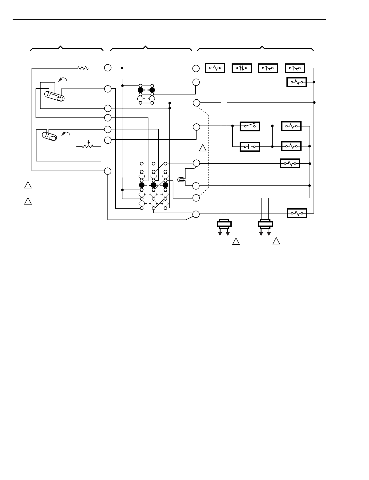
T874 MULTISTAGE THERMOSTATS AND Q674 SUBBASES
60-2485—8126
Fig. 102. Schematic and hookup of T874J,R with Q674L. Used in heat pump applications.
H2 FALL
H1
FALL
C1
L1
(HOT)
L2 1L1
(HOT)
L2 1
2
POWER SUPPLY. PROVIDE DISCONNECT
MEANS AND OVERLOAD PROTECTION
AS REQUIRED.
FIELD WIRE JUMPER TO ALLOW SINGLE
SYSTEM TRANSFORMER.
1
2
THERMOSTAT SUBBASE SYSTEM COMPONENTS
H1/C1
ANTICIPATOR
H2 ANTICIPATOR
SYSTEM
SWITCH
FAN
SWITCH
AUTO
ON
OFF
HEAT
EM. HT.
COOL
INTERNAL
THERMOSTAT
OVERLOAD
SWITCH
SUPPL. ELEC.
HT. RELAY
COOL CHANGEOVER
VALVE
COMPRESSOR
CONTACTOR
M4726
EM. HT.
LED (RED)
EM. HT. RELAY
TIME DELAY
FAN RELAY
OUTDOOR
THERMOSTAT
EM. HT.
RELAY CONTACT
FAN RELAY
HIGH
PRESSURE
SWITCH
R
VR
X
E
Y
V
F
M
1
2
3
4
5
6
7
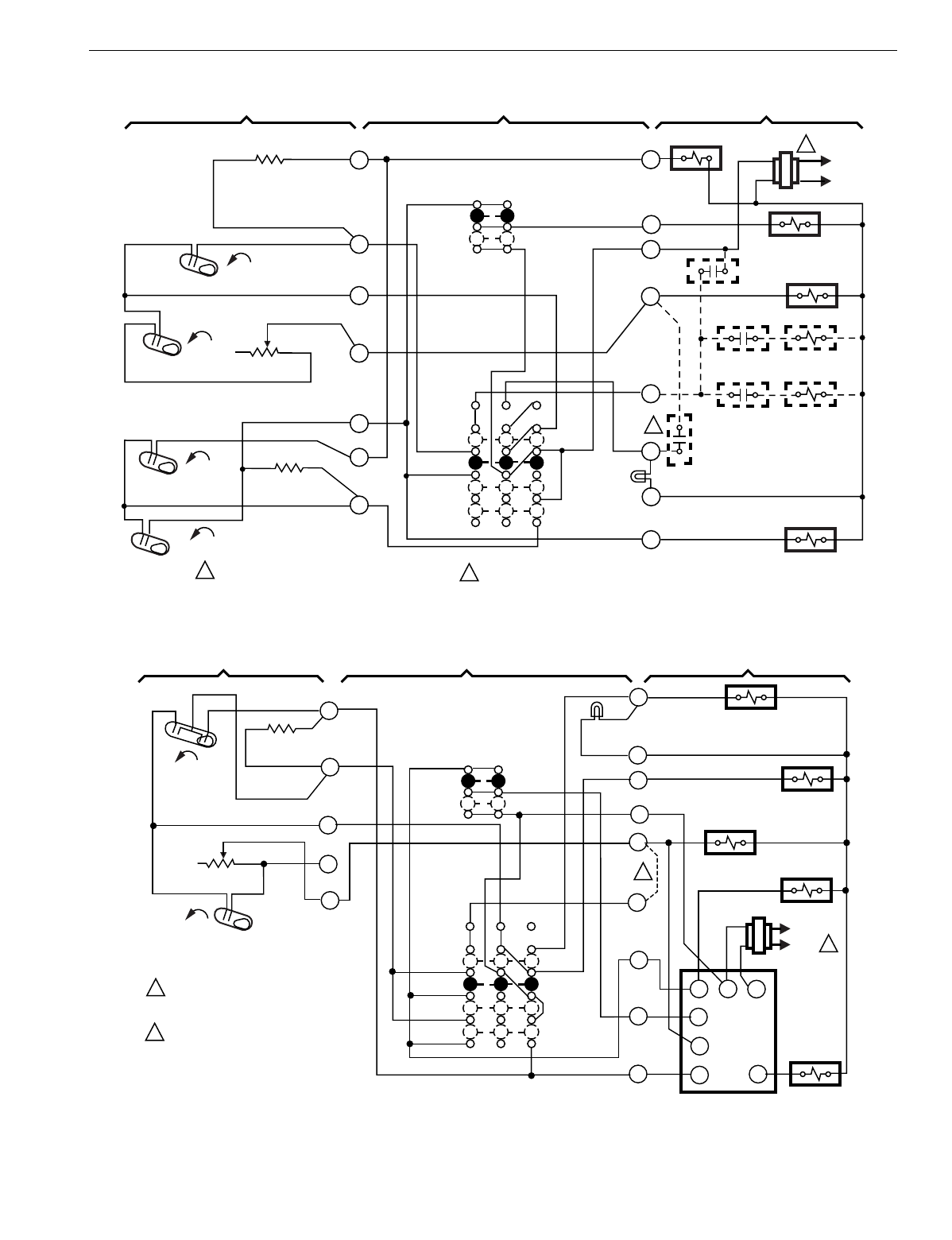
T874 MULTISTAGE THERMOSTATS AND Q674 SUBBASES
127 60-2485—8
Fig. 103. Schematic and hookup of T874G with Q674L. Used in heat pump applications.
Fig. 104. Schematic and hookup of T874R with Q674L. Used in heat pump applications.
H2 ANTICIPATOR
1
SUPL. HT.
LED (RED)
M4665
POWER SUPPLY. PROVIDE DISCONNECT MEANS
AND OVERLOAD PROTECTION AS REQUIRED.
1
SYSTEM COMPONENTSSUBBASETHERMOSTAT
L1
(HOT)
L2
1
H1 FALL
H2 FALL
2
4
6
O
G
R
W2
E
L
C
Y
CO RISE
C1 RISE
8
9
10
H1 ANTICIPATOR
C1 ANTICIPATOR
SYSTEM
SWITCH
SUPL. HT.
COOL
OFF
FAN
SWITCH
AUTO
ON FAN RELAY
COOL CHANGEOVER VALVE
OUTDOOR
THERMOSTAT
HEAT RELAY 1
HEAT RELAY
CONTACT 1 HEAT RELAY 2
HEAT RELAY
CONTACT 2 HEAT RELAY 3
2
COMPRESSOR
CONTACTOR 1
N.O. SWITCH – INSTALLER ADDED, TO LIGHT SUPL. HT. LED
WHEN COMPRESSOR OPERATION IS NOT NORMAL.
2
COMPRESSOR
FAULT
HEAT
1
1
2
L1
(HOT)
L2
2
POWER SUPPLY. PROVIDE DISCONNECT
MEANS AND OVERLOAD PROTECTION
AS REQUIRED.
OPTIONAL FIELD WIRE JUMPER TO CYCLE
AUXILIARY HEAT RELAY H1 INSTEAD OF
H2 (FASTER RESPONSE).
THERMOSTAT SUBBASE SYSTEM COMPONENTS
M4728
FAN
SWITCH
AUTO
ON
EM. HT. LED
(RED)
O
G
Y
H
W2
B
X
E
2
3
4
H2
FALL
H2 ANTICIPATOR
5
6
COM
EH
R8233B
YR
G
W
O
R
SYSTEM
SWITCH
OFF
HEAT
EM. HT.
COOL
H1
FALL
C1
EM. HT. RELAY
AUX. HT. RELAY
"B" RELAY
COMPRESSOR
CONTACTOR
ELEC. HT.
RELAY
H1/C1
ANTICIPATOR
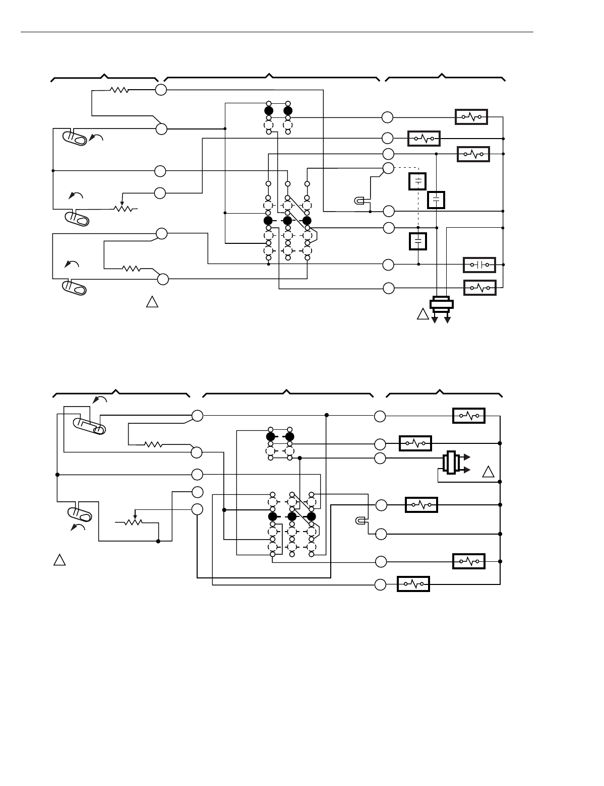
T874 MULTISTAGE THERMOSTATS AND Q674 SUBBASES
60-2485—8128
Fig. 105. Schematic and hookup of T874C with Q674L. Used in heat pump applications.
Fig. 106. Schematic and hookup of T874R with Q674L. Used in heat pump applications.
OFF
COOL
IHRI
RHI
FAN SWITCH
ON
SYSTEM
SWITCH
SYSTEM
MONITOR
SWITCH
1POWER SUPPLY. PROVIDE DISCONNECT MEANS AND OVERLOAD
PROTECTION AS REQUIRED.
M8384
EM. HT. RELAY
1
EM. HT. LED
(RED)
W2
2
EM. HT.
HEAT
FAN RELAY
HEAT RELAY 2
HEAT RELAY 1
W1
AUTO
C
Y
H1 FALL
H2 ANTICIPATOR
H1 ANTICIPATOR
C1 ANTICIPATOR
H2
FALL
C1
RISE
COMPRESSOR
CONTRACTOR
8
10
L1
(HOT)
L2
1
G
K
L
R
THERMOSTAT SUBBASE SYSTEM COMPONENTS
4
6
H2
FALL
H1
FALL
C1
L1
(HOT)
L2 1
1POWER SUPPLY. PROVIDE DISCONNECT
MEANS AND OVERLOAD PROTECTION
AS REQUIRED.
THERMOSTAT SUBBASE SYSTEM COMPONENTS
H1/C1
ANTICIPATOR
H2 ANTICIPATOR
SYSTEM
SWITCH
FAN SWITCH
AUTO
ON
OFF
HEAT
EM. HT.
COOL
AUX. HT. RELAY
EM. HT. RELAY
COOL CHANGEOVER
VALVE
COMPRESSOR
CONTACTOR
FAN RELAY
M4724
2
3
4
5
6
E
Y
X
W2
R
G
O
EM. HT.
LED
(RED)
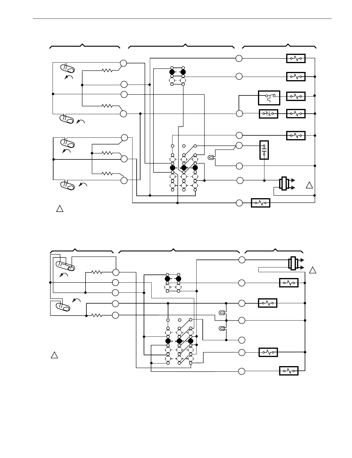
T874 MULTISTAGE THERMOSTATS AND Q674 SUBBASES
129 60-2485—8
Fig. 107. Schematic and hookup of T874D with Q674L. Used in heat pump applications.
Fig. 108. Schematic and hookup of T874R with Q674L. Used in heat pump applications.
C2 RISE
C1
RISE
H2 FALL
H1
FALL
L1
(HOT)
L2
1
1
POWER SUPPLY. PROVIDE DISCONNECT MEANS AND OVERLOAD PROTECTION AS REQUIRED.
THERMOSTAT SUBBASE SYSTEM COMPONENTS
H1
ANTICIPATOR
C2 ANTICIPATOR
H2
ANTICIPATOR
C1 ANTICIPATOR
SYSTEM
SWITCH
FAN
SWITCH
AUTO
ON
OFF
HEAT
EM. HT.
COOL
M4727
Y
R
C
L
E
Y1
G
O
11
10
8
5
4
3
2
EM. HT.
LED (RED)
COMPRESSOR
CONTACTOR 1
COMP.
FAILURE
EM. HT.
RELAY CONTACT
EM. HT. RELAY
COMPRESSOR
CONTACTOR 2
OUTDOOR
THERMSTAT SUPPL. HT.
RELAY
FAN RELAY
COOL CHANGEOVER
VALVE
H2
FALL
H1
FALL
C1
L1
(HOT)
L2 1
1POWER SUPPLY. PROVIDE DISCONNECT
MEANS AND OVERLOAD PROTECTION
AS REQUIRED.
THERMOSTAT SUBBASE SYSTEM COMPONENTS
H1/C1
ANTICIPATOR
H2
ANTICIPATOR
FAN
SWITCH
AUTO
ON
SYSTEM
SWITCH
EM. HT.
HEAT
OFF
COOL
AUX. HT. RELAY
FAN RELAY
COOL CHANGEOVER
VALVE
COMPRESSOR
CONTACTOR
M4725
2
3
4
5
6
R
G
W
B
X
O
Y
AUX. HT.
LED (YELLOW)
EM. HT.
LED (RED)
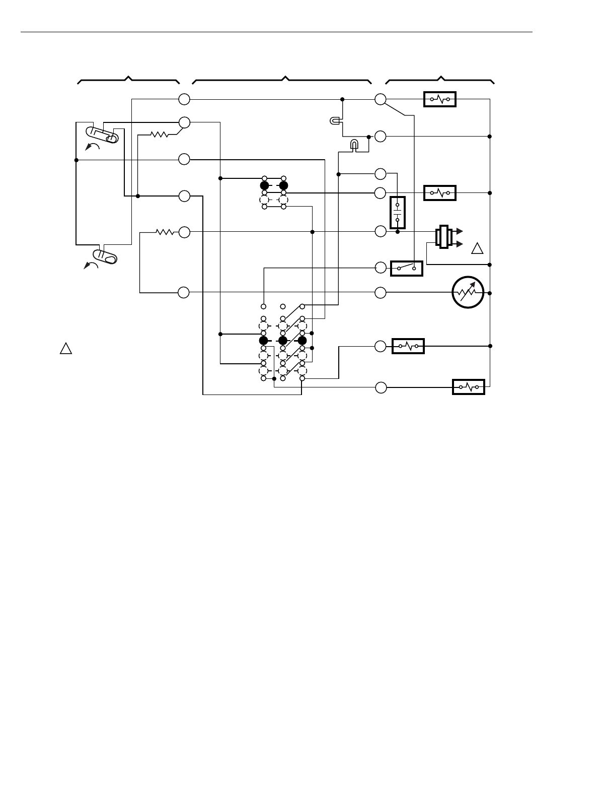
T874 MULTISTAGE THERMOSTATS AND Q674 SUBBASES
60-2485—8130
Fig. 109. Schematic and hookup of T874R with Q674L. Used in heat pump applications.
H2
FALL
L1
(HOT)
L2 1
1POWER SUPPLY. PROVIDE DISCONNECT
MEANS AND OVERLOAD PROTECTION
AS REQUIRED.
THERMOSTAT SUBBASE SYSTEM COMPONENTS
H1
FALL
C1 H1/ C1
ANTICIPATOR
SYSTEM
SWITCH
FAN
SWITCH
AUTO
ON
OFF
HEAT
EM. HT.
COOL
AUX. HT. RELAY
FAN RELAY
AUX. HT.
LED (GREEN)
COOL
CHANGEOVER
VALVE
COMPRESSOR
FAILURE
EM. HT.
LED (RED)
OUTDOOR
THERMOSTAT
OUTDOOR
THERMISTOR
COMPRESSOR
CONTACTOR
Y
O
X2
T
R
F
B
W
G
1
2
3
4
5
6
RESET
HEATER
M5071
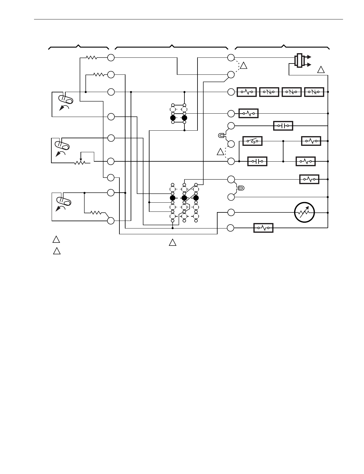
T874 MULTISTAGE THERMOSTATS AND Q674 SUBBASES
131 60-2485—8
Fig. 110. Schematic and hookup of T87C,R with Q674L. Used in heat pump applications.
L1
(HOT)
L2
1
F
EM. HT.
LED (YELLOW)
R
SYSTEM
SWITCH
EM. HT.
HEAT
OFF
COOL
H1
ANTICIPATOR
1POWER SUPPLY. PROVIDE DISCONNECT MEANS
AND OVERLOAD PROTECTION AS REQUIRED.
M2854
VR
H1
FALL
E
AUTO
ON
FAN SWITCH
A
L
M
OUTDOOR
THERMOSTAT SUPL. ELEC.
HT. RELAY
X
COMPRESSOR
CONTACTOR
OVERLOAD
SWITCH
INTERNAL
THERMOSTAT
HI PRESSURE
SWITCH
FAN
RELAY
EM. HT. RELAY
CONTACT TIME DELAY
FAN RELAY
ELEC. HT. RELAY
H2
FALL
H2
ANTICIPATOR
C1
RISE
C1
ANTICIPATOR
REMOVE FACTORY INSTALLED V-VR JUMPER WHEN
CONNECTING A TWO TRANSFORMER SYSTEM.
2
2
SERVICE
S
Y
C815A OUTDOOR
THERMISTOR
COOL CHANGEOVER
VALVE
V
SERVICE
LED (RED)
3
RESET
REMOVE FACTORY-INSTALLED S-Y JUMPER TO DISABLE SERVICE LIGHT.
3
10
8
7
6
5
4
3
2
1
THERMOSTAT SUBBASE SYSTEM COMPONENTS
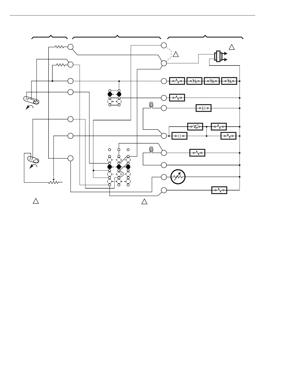
T874 MULTISTAGE THERMOSTATS AND Q674 SUBBASES
60-2485—8132
Fig. 111. Schematic and hookup of T874R with Q674L. Used in heat pump applications.
L1
(HOT)
L2
1
COOL
HEAT
FALL
H2
SYSTEM
SWITCH
1POWER SUPPLY. PROVIDE DISCONNECT MEANS AND
OVERLOAD PROTECTION AS REQUIRED. M2851
OFF
H1 C1
2REMOVE FACTORY INSTALLED V-VR JUMPER WHEN
CONNECTING A TWO TRANSFORMER SYSTEM.
COMPRESSOR
CONTACTOR
OVERLOAD
SWITCH
INTERNAL
THERMOSTAT
HIGH
PRESSURE
SWITCH
2
V
VR
M
F
L
Y
E
X
A
R
FAN RELAY SERVICE
OUTDOOR
THERMOSTAT
EM. HT.
RELAY
SUPPL. ELEC.
HT. RELAY
EM. HT.
RELAY EM. HT.
RELAY
C815A
OUTDOOR
THERMISTOR
COOL CHANGEOVER
VALVE
EM. HT. LED
(YELLOW)
SERVICE
LED (RED)
EM. HT.
AUTO
ON
FAN
SWITCH
RESET
HEATER
H1/ C1
ANTICIPATOR
H2
ANTICIPATOR
FALL
THERMOSTAT SUBBASE SYSTEM COMPONENTS
1
2
3
4
5
6
7
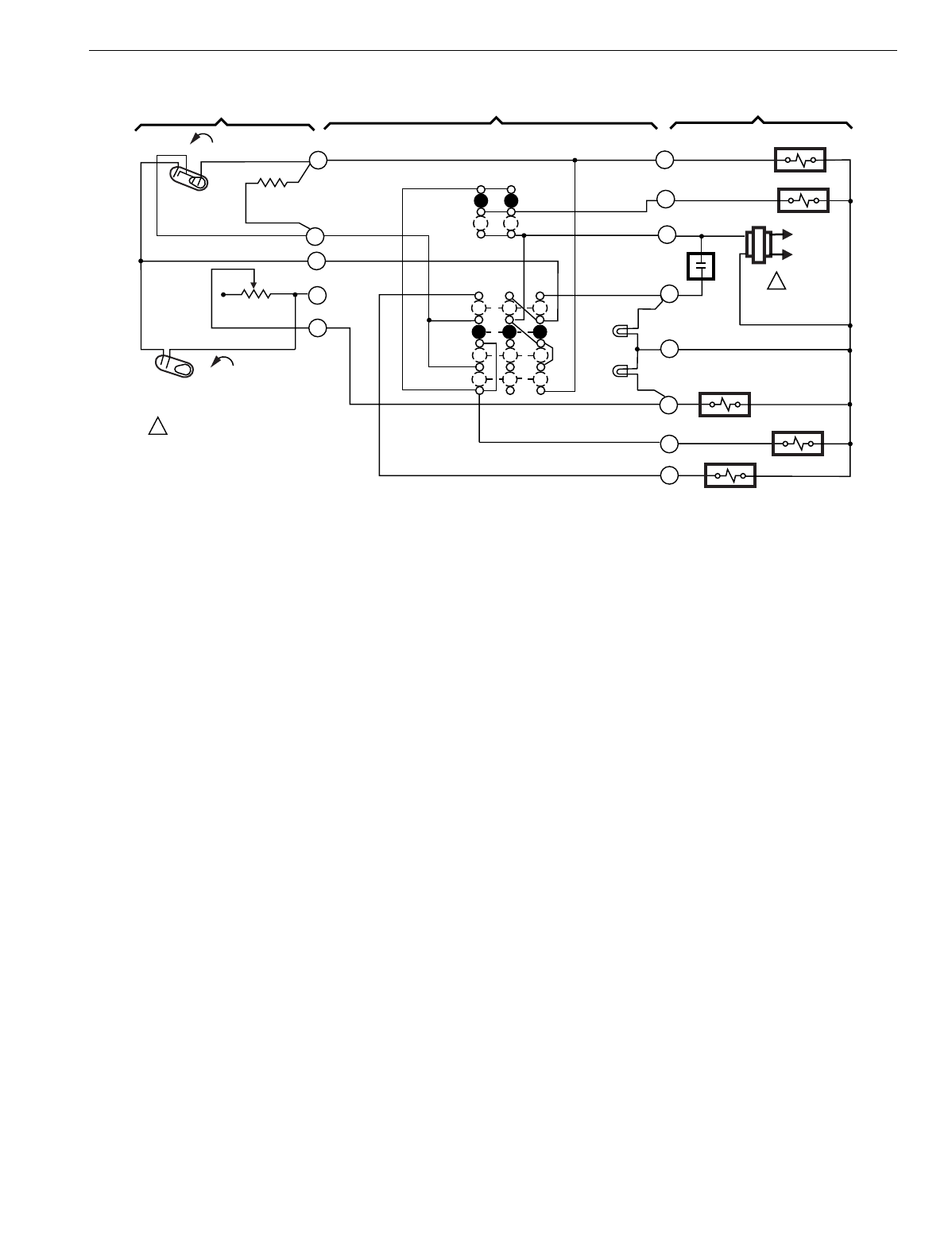
T874 MULTISTAGE THERMOSTATS AND Q674 SUBBASES
133 60-2485—8
Fig. 112. Schematic and hookup of T874R with Q674L. Used in heat pump applications.
OFF
COOL
COMPRESSOR
FAILURE
FAN
SWITCH
ON
SYSTEM
SWITCH
1POWER SUPPLY. PROVIDE DISCONNECT
MEANS AND OVERLOAD
PROTECTION AS REQUIRED.
M8383
AUX. HT. RELAY
4
EM. HT. LED
(RED)
AUX. HT. LED
(GREEN)
EM. HT.
HEAT
COOL CHANGEOVER
VALVE
FAN RELAY
EM. HT. RELAY
AUTO
Y
C1
H1
FALL
H1/C1
ANTICIPATOR
H2
ANTICIPATOR
H2 FALL
COMPRESSOR
CONTACTOR
6
O
5
R
W2
L1
(HOT)
L2
1
G
2
3
E
X
L1
THERMOSTAT SUBBASE SYSTEM COMPONENTS
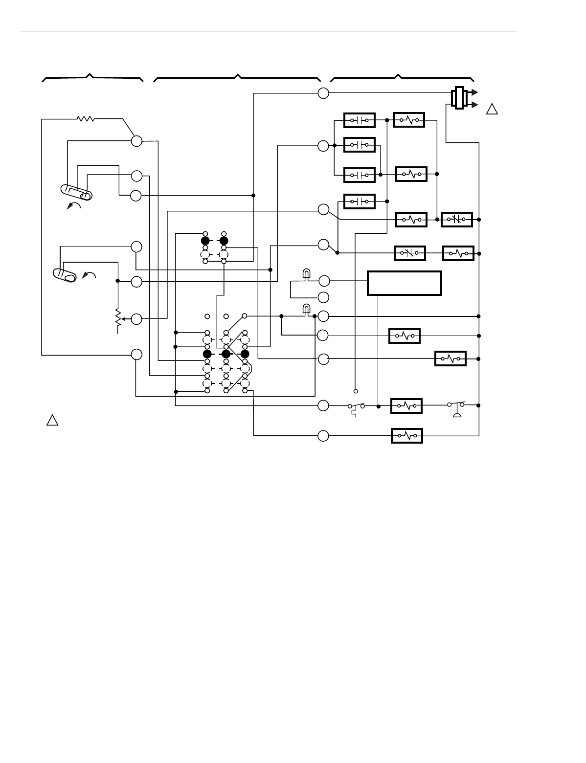
T874 MULTISTAGE THERMOSTATS AND Q674 SUBBASES
60-2485—8134
Fig. 113. Schematic and hookup of T874R with Q674L. Used in heat pump applications.
H2
H1
FALL
C1
L1
(HOT)
L2 1
1POWER SUPPLY. PROVIDE DISCONNECT MEANS AND
OVERLOAD PROTECTION AS REQUIRED.
THERMOSTAT SUBBASE SYSTEM COMPONENTS
H1/C1
ANTICIPATOR
FALL
H2 ANTICIPATOR
SYSTEM
SWITCH
FAN
SWITCH
AUTO
ON
OFF
HEAT
EM. HT.
LED (RED)
EM. HT.
COOL
EM. HT. RELAY
EM. HT. RELAY
EM. HT. RELAY
DEFROST RELAY
DEFROST
RELAY
FAN RELAY
M4720
COMPRESSOR
CONTACTOR
HIGH
PRESSURE
SWITCH
COOL CHANGEOVER
VALVE
LOW AMBIENT
CUTOFF
O
Y
G
E
X1
X2
L
CHECK LED
(GREEN)
OPTIONAL COMP.
FAILURE DEVICE
B
W2
W3
R
HEAT
CONTRACTOR 3
HEAT
CONTRACTOR 2
OUTDOOR
THERMOSTAT
HEAT
CONTRACTOR 1
HIGH LIMIT
SWITCH
REVERSING
VALVE
1
2
3
4
5
6
7
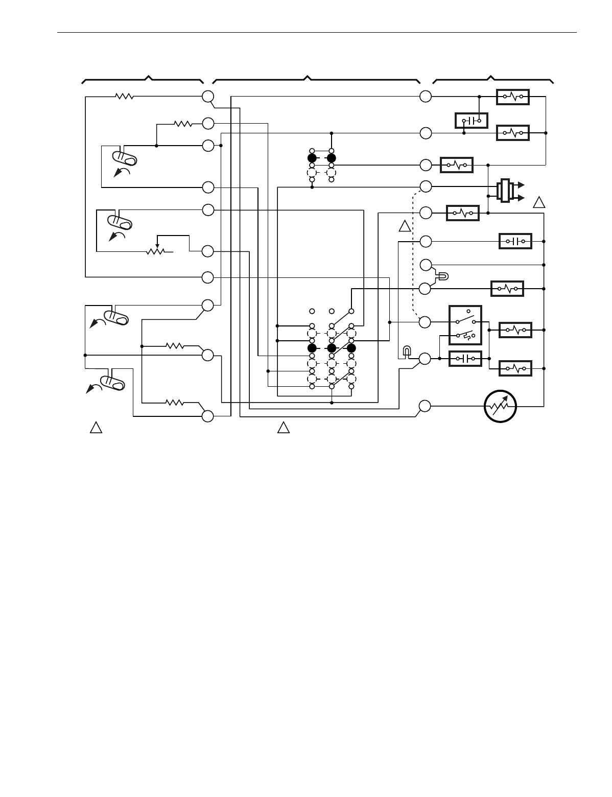
T874 MULTISTAGE THERMOSTATS AND Q674 SUBBASES
135 60-2485—8
Fig. 114. Schematic and hookup of T874D with Q674L. Used in heat pump applications.
L1
(HOT)
L2 1
F
E
SYSTEM
SWITCH
EM. HT.
HEAT
OFF
COOL
H1
ANTICIPATOR
1POWER SUPPLY. PROVIDE DISCONNECT MEANS
AND OVERLOAD PROTECTION AS REQUIRED.
M2
H1
FALL
R
AUTO
ON
FAN SWITCH
X
V
M
L
FAN
RELAY
H2
FALL
H2 ANTICIPATOR
C1
RISE
C2
RISE
C2
ANTICIPATOR
REMOVE FACTORY INSTALLED V-VR JUMPER WHEN CONNECTING
A TWO TRANSFORMER SYSTEM.
2
2
VR
Y
A
OUTDOOR
THERMOSTAT HIGH SPEED
COMPRESSOR
CONTACTOR
LOW SPEED
COMPRESSOR
CONTACTOR
COOL
CHANGEOVER
VALVE
OUTDOOR
THERMOSTAT
SUPPL. ELEC.
HT. RELAY
SUPPL. ELEC.
HT. RELAY
EM. HT.
RELAY
C815A OUTDOOR
THERMISTOR
M2853
EM. HT. LED
(YELLOW)
EM. HT.
RELAY
SERVICE
LED (RED)
RESET
HEATER
C1
ANTICIPATOR
SERVICE
1
2
3
4
5
6
7
8
10
11
THERMOSTAT SUBBASE SYSTEM COMPONENTS
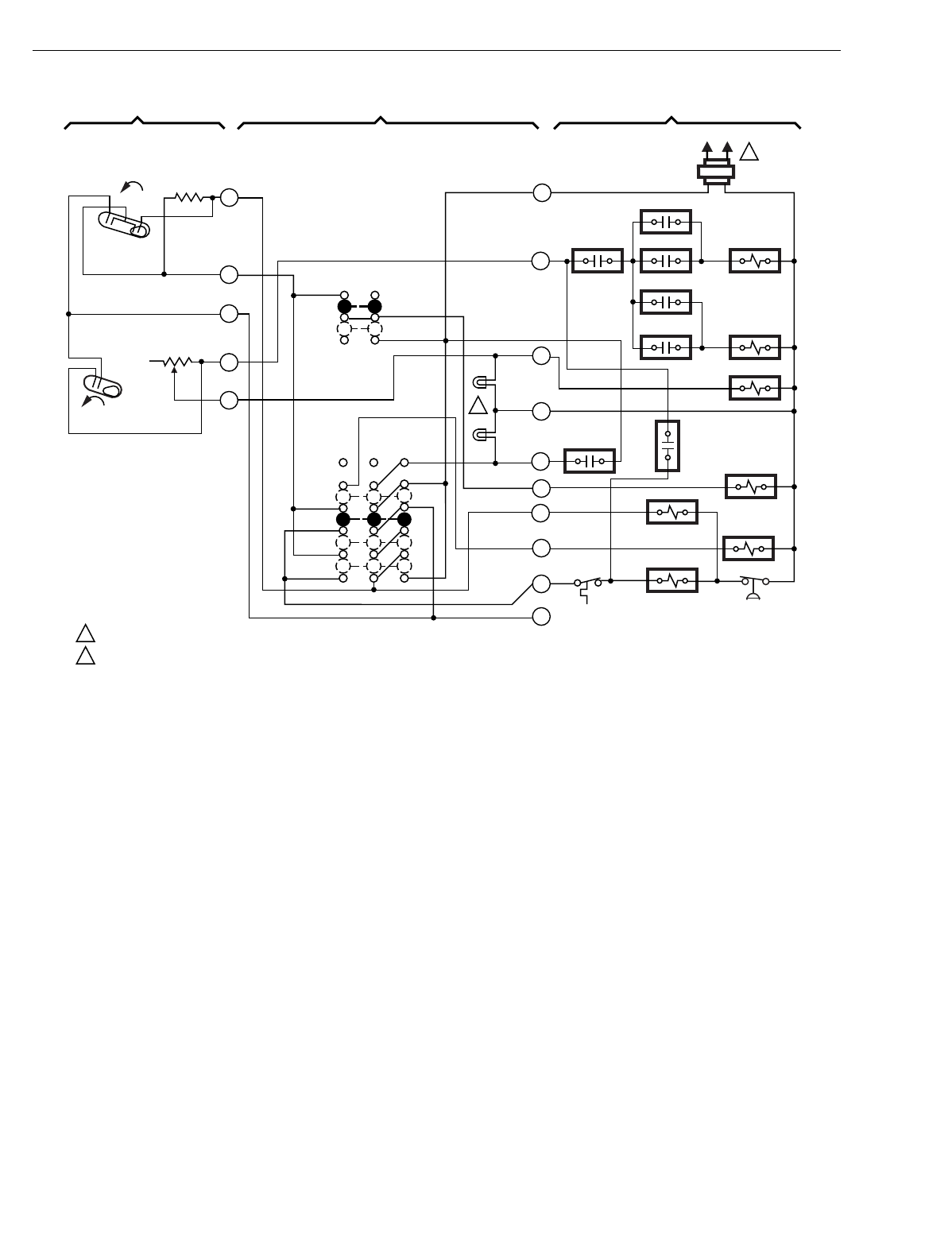
T874 MULTISTAGE THERMOSTATS AND Q674 SUBBASES
60-2485—8136
Fig. 115. Schematic and hookup of T874R with Q674L. Used in heat pump applications.
M5072A
(HOT) L1 L2
1
LACO CHP
Y
B
E
O
G
L
X
W2
W3
RODT 1
RTD 1 EHR 1 RTD 2
ODT 2
EHR 2 RTD 3
RD
SYSTEM
MONITOR
FAN RELAY
COMPRESSOR
CONTACTOR
COOL CHANGEOVER
VALVE
EM. HT.
RELAY
RTD 1
AUX. HT.
LED
(GREEN)
EM. HT.
LED (RED)
FAN SWITCH
ON
AUTO
SYSTEM
SWITCH
EM. HT.
HEAT
OFF
COOL
H2
FALL
H1
FALL
C1
2
3
4
5
6
H1/C1
ANTICIPATOR
H2
ANTICIPATOR
1POWER SUPPLY. PROVIDE DISCONNECT MEANS AND OVERLOAD PROTECTION AS REQUIRED.
AUXILIARY HEAT LED AVAILABLE ON SOME MODELS.
THERMOSTAT SUBBASE SYSTEM COMPONENTS
2
2
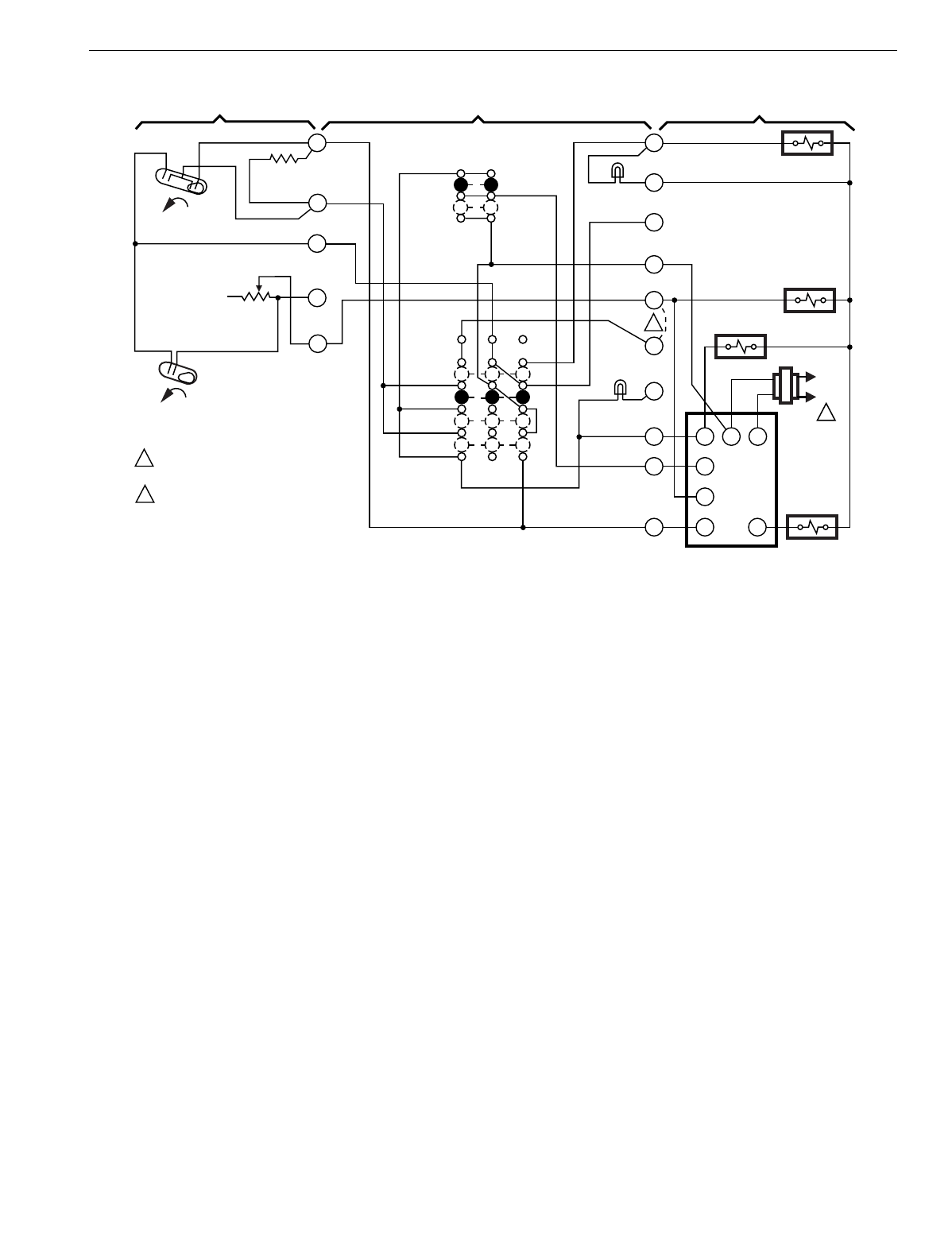
T874 MULTISTAGE THERMOSTATS AND Q674 SUBBASES
137 60-2485—8
Fig. 116. Schematic and hookup of T874R with Q674L. Used in heat pump applications.
H2
FALL
H1
FALL
C1
YR
COM
G
W
OEH
O
G
Y
A
H
W2
R
B
X
E
L1
(HOT)
L2
1
COMPRESSOR
CONTACTOR
AUX. HT. RELAY
EM. HT. RELAY
EM. HT.
LED (RED)
EM. HT.
HEAT
OFF
COOL
COMP. FAULT
LED (YELLOW)
SYSTEM
SWITCH
FAN
SWITCH
AUTO
ON
1 POWER SUPPLY. PROVIDE DISCONNECT
MEANS AND OVERLOAD PROTECTION
AS REQUIRED.
OPTIONAL FIELD WIRE JUMPER TO CYCLE
AUXILIARY HEAT RELAY WITH H1 INSTEAD
OF H2 (FASTER RESPONSE).
2ELEC.
HT. RELAY
M2857
H1/C1
ANTICIPATOR
H2 ANTICIPATOR
2
R8233B
THERMOSTAT SYSTEM COMPONENTS
SUBBASE
2
5
6
4
3
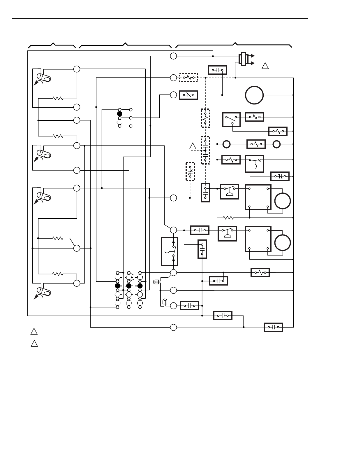
T874 MULTISTAGE THERMOSTATS AND Q674 SUBBASES
60-2485—8138
Fig. 117. Schematic and hookup of T874D with Q674L. Used in heat pump applications.
H1
FALL
L1
(HOT)
L2
R
B
2
3
4
5
6
G
Y1
Y2
W
X
L
O
ENTHALPY
CONTROL RELAY
HEAT RELAY
CONTACT 1
DEFROST
RELAY
H1 ANTICIPATOR
H2 ANTICIPATOR
C1 ANTICIPATOR
C2 ANTICIPATOR
2
2
1
1
POWER SUPPLY. PROVIDE DISCONNECT MEANS AND OVERLOAD
PROTECTION AS REQUIRED.
OPTIONAL ECONOMIZER HOOKUP (DOTTED LINES).
M7755
H2
FALL
8
10
11
C1
RISE
C2
RISE
THERMOSTAT SUBBASE SYSTEM COMPONENTS
MOTOR
3
MOTOR
1
OUTDOOR
FAN RELAY 1
DEFROST SWITCH
RELAY
TM1 TM2
OUTDOOR
FAN RELAY 2
DEFROST
SWITCH
LOW AMBIENT
THERMOSTAT 1
OUTDOOR
FAN RELAY 3
1ST STAGE
SHORT
CYCLE
CONTROL
2ND STAGE
SHORT
CYCLE
CONTROL
1ST STAGE LOW
PRESSURE LIMIT
2ND STAGE LOW
PRESSURE LIMIT
TIME DELAY
HEATER
ECONOMIZER
RELAY
ENTHALPY
CONTROL
ENTHALPY
CONTROL
RELAY 2
ENTHALPY
CONTROL
RELAY 1
TIME DELAY
DEFROST
RELAY
HEAT
RELAY 1
OUTDOOR
THERMOSTAT
SERVICE
DEFROST
RELAY
COOL CHANGEOVER
VALVE
SYSTEM
SWITCH
OFF
COOL
HEAT
EM. HT. LED
(GREEN)
SERVICE
LED (RED)
FAN
SWITCH
AUTO
ON
MOTOR
2
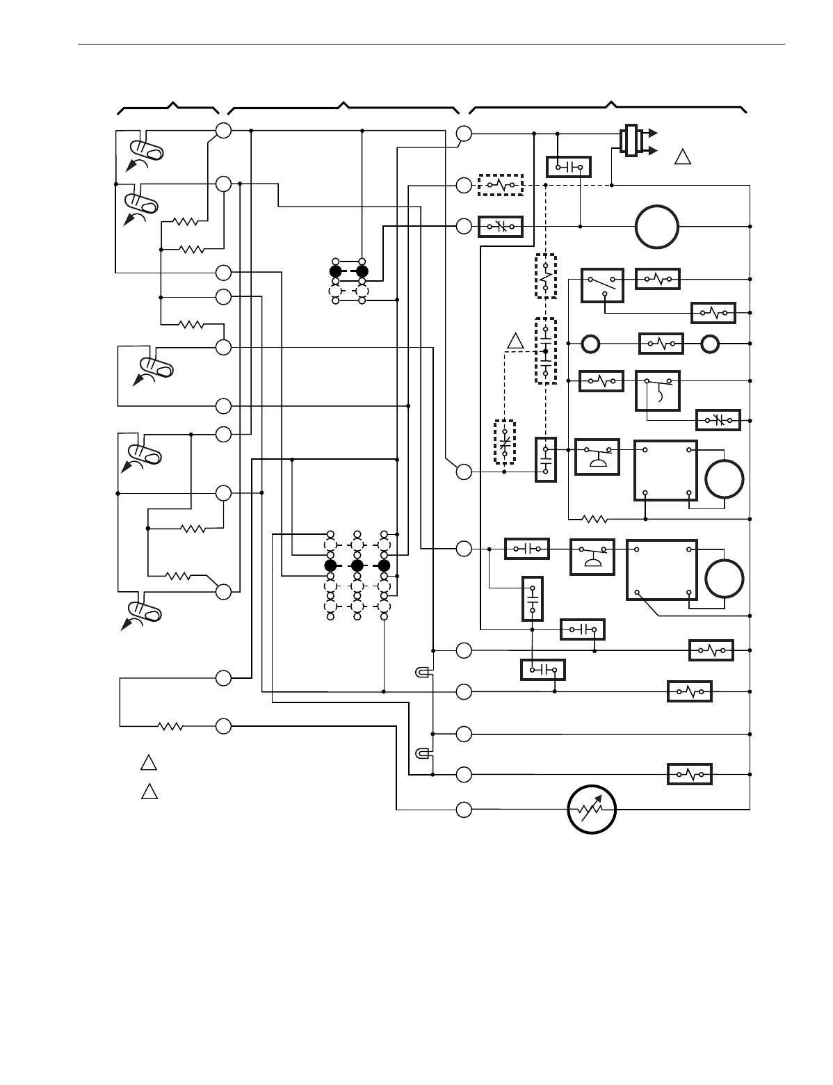
T874 MULTISTAGE THERMOSTATS AND Q674 SUBBASES
139 60-2485—8
Fig. 118. Schematic and hookup of T874W with Q674L. Used in heat pump applications.
H1
FALL
H2
FALL
L1
(HOT)
L2
R
B
2
1
3
4
5
6
G
Y1
Y2
O
X
E
A
ECONOMIZER
RELAY
HEAT RELAY
CONTACT 1
DEFROST
RELAY
H2 ANTICIPATOR
H1
ANTICIPATOR
H3
ANTICIPATOR
C2 ANTICIPATOR
C1 ANTICIPATOR
RESET HEATER
2
2
1
1
POWER SUPPLY. PROVIDE DISCONNECT MEANS
AND OVERLOAD PROTECTION AS REQUIRED.
OPTIONAL ECONOMIZER HOOKUP (DOTTED LINES).
M7756
H3
FALL
8
9
10
11
12
C1
RISE
C2
RISE
THERMOSTAT SUBBASE SYSTEM COMPONENTS
MOTOR
3
MOTOR
1
MOTOR
2
OUTDOOR
FAN RELAY 1
DEFROST SWITCH
RELAY
DEFROST
RELAY
TM1 TM2
OUTDOOR
FAN RELAY 2
DEFROST
SWITCH
OUTDOOR
THERMOSTAT 1
OUTDOOR
FAN RELAY 3
1ST STAGE
SHORT
CYCLE
CONTROL
2ND STAGE
SHORT
CYCLE
CONTROL
1ST STAGE LOW
PRESSURE LIMIT
2ND STAGE LOW
PRESSURE LIMIT
TIME DELAY
HEATER
ECONOMIZER
RELAY
ENTHALPY
CONTROL
ECONO-
MIZER
RELAY 2
ECONOMISER
RELAY 1
TIME DELAY
RELAY
DEFROST
RELAY
COOL CHANGEOVER
VALVE
EMERGENCY
HEAT RELAY
W
AUXILIARY
HEAT RELAY
SYSTEM
SWITCH
OFF
COOL
HEAT
EM. HT.
AUX. HEAT
LED (GREEN)
EM. HEAT
LED (RED)
FAN
SWITCH
AUTO
ON
DEFROST
RELAY
CONTACT
DEFROST
RELAY
CONTACT
C815 OUTDOOR
THERMISTOR
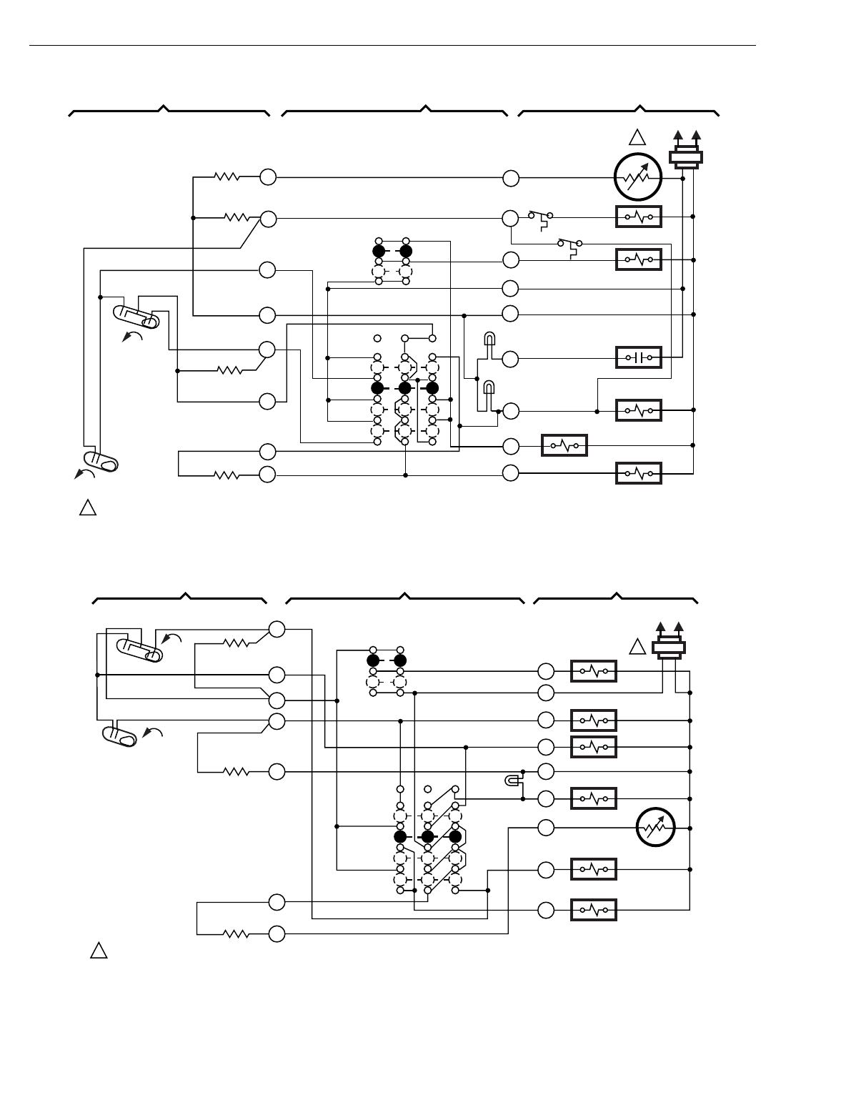
T874 MULTISTAGE THERMOSTATS AND Q674 SUBBASES
60-2485—8140
Fig. 119. Schematic and hookup of T874R with Q674L. Used in heat pump applications.
Fig. 120. Schematic and hookup of T874R with Q674L. Used in heat pump applications.
H1
FALL
C1
L1
(HOT)
L2
1
H2
FALL
SYSTEM
SWITCH
EM. HT.
HEAT
OFF
COOL
H1 ANTICIPATOR
C1
ANTICIPATOR
POWER SUPPLY. PROVIDE DISCONNECT MEANS AND OVERLOAD PROTECTION AS REQUIRED.
RESET
HEATER
H2 ANTICIPATOR
FAN SWITCH
AUTO
ON
C815A
OUTDOOR
THERMISTOR
AUX. HT. RELAY
FAN RELAY
SERVICE
EM. HT. RELAY
COMPRESSOR
CONTACTOR
HEAT CHANGEOVER
RELAY
12
6
5
4
3
2
1T
W2
G
X
SERVICE LED
(YELLOW)
EM. HT.
LED (RED)
Z
K
Y
W1
R
11
1
THERMOSTAT SUBBASE SYSTEM COMPONENTS
M5955
H2 FALL
H1 FALL
C1
L1
(HOT) L2
1
FAN SWITCH
AUTO
ON
FAN RELAY
AUX. HT. RELAY
"H" RELAY
EM. HT. RELAY
CHANGEOVER VALVE (COOL)
COMPRESSOR
CONTACTOR
C815A1039
THERMISTOR
SYSTEM
SWITCH
EM. HT.
HEAT
OFF
COOL
EM. HT.
LED (RED)
G
R
W
H
B
X
T
O
Y
12
11
6
5
4
3
2
H1/C1
ANTICIPATOR
H2
ANTICIPATOR
RESET HEATER
POWER SUPPLY. PROVIDE DISCONNECT MEANS AND OVERLOAD PROTECTION AS REQUIRED. M3173B
THERMOSTAT SUBBASE SYSTEM COMPONENTS
1
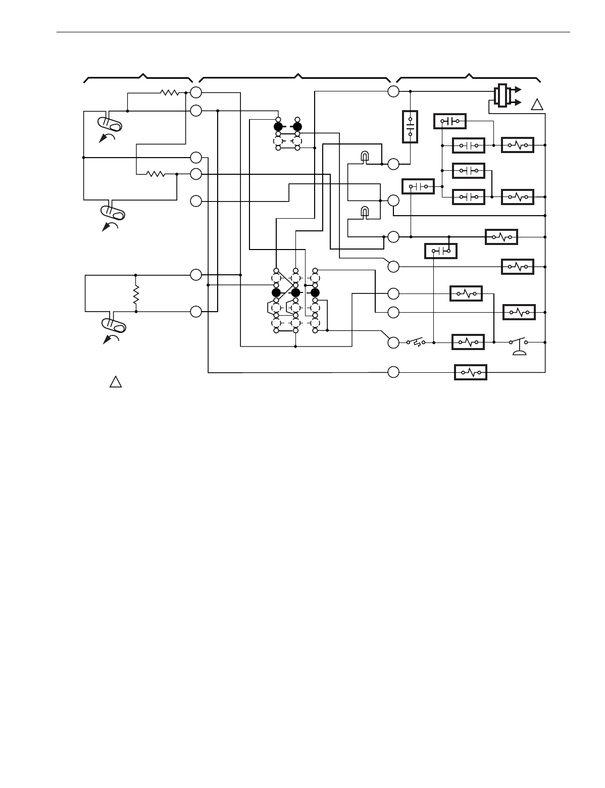
T874 MULTISTAGE THERMOSTATS AND Q674 SUBBASES
141 60-2485—8
Fig. 121. Schematic and hookup of T874C with Q674L. Used in heat pump applications.
L1
(HOT)
L2 1
R
L
X
W2
G
O
E
B
Y
ODT1
EHR1
ODT2
EHR2
RTD2
RTD3
RTD1
COMPRESSOR
FAILURE
HEAT CHANGEOVER
VALVE
COMPRESSOR
CONTACTOR
LACO CHP
EM. HT.
RELAY
COOL CHANGEOVER
VALVE
FAN RELAY
RD
RTD1
H1
FALL
H2
FALL
C1
RISE
2
3
4
5
6
8
10
AUX. HT.
LED (GRN)
EM. HT.
LED (RED)
AUTO
ON
FAN
SWITCH
SYSTEM
SWITCH
EM. HT.
HEAT
OFF
COOL
H2 ANTICIPATOR
H1 ANTICIPATOR
1POWER SUPPLY. PROVIDE DISCONNECT MEANS AND OVERLOAD
PROTECTION AS REQUIRED.
M7012
C1
ANTICIPATOR
THERMOSTAT SUBBASE SYSTEM COMPONENTS
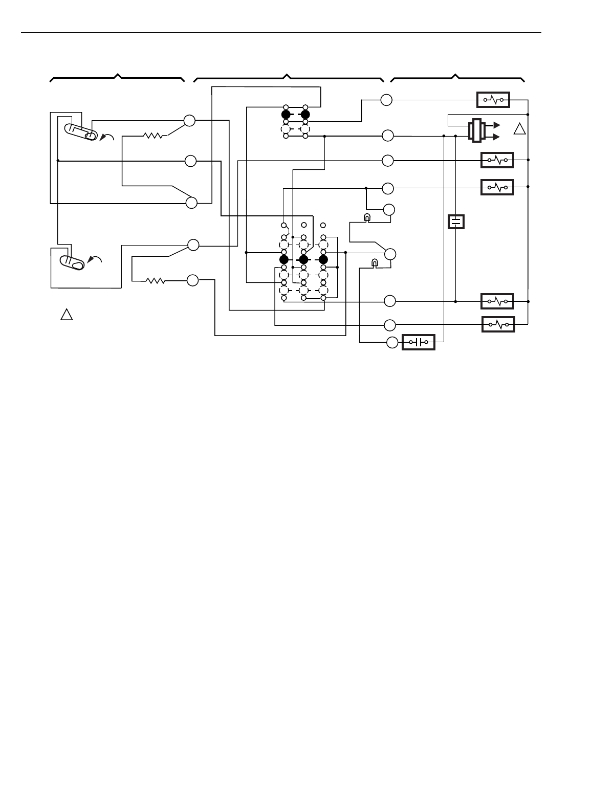
T874 MULTISTAGE THERMOSTATS AND Q674 SUBBASES
60-2485—8142
Fig. 122. Schematic and hookup of T874R with Q674L. Used in heat pump applications.
H1 C1
2
3
H2
FALL 5
6
H1/C1
ANTICIPATOR
H2
ANTICIPATOR
AUTO
ON
SYSTEM
SWITCH
EM. HT.
HEAT
OFF
COOL
FAN RELAY
G
R
K
L
1
C
Y
W1
SERVICE
LED (RED)
EM. HT. LED
(YELLOW)
SERVICE
COMPRESSOR
CONTACTOR
EM. HT. RELAY
AUX. HT. RELAY
POWER SUPPLY. PROVIDE DISCONNECT
MEANS AND OVERLOAD
PROTECTION AS REQUIRED.
1
CO
L1
(HOT)
L2
CHANGEOVER
VALVE
FALL
4
W2
M8379
THERMOSTAT SUBBASE SYSTEM COMPONENTS
FAN
SWITCH
Z
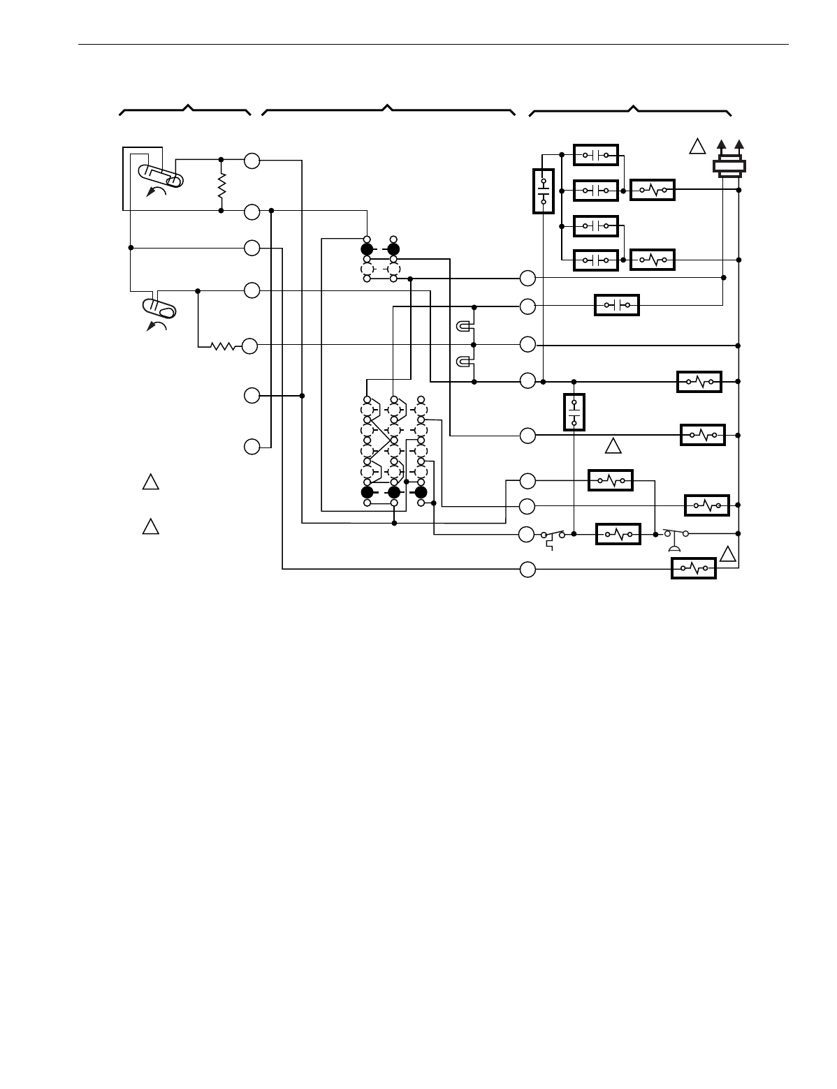
T874 MULTISTAGE THERMOSTATS AND Q674 SUBBASES
143 60-2485—8
Fig. 123. Schematic and hookup of T874R with Q674L. Used in heat pump applications.
H2
FALL
H1
FALL
C1
L1
(HOT) L2
1
2
2
1
2
POWER SUPPLY. PROVIDE
DISCONNECT MEANS AND
OVERLOAD PROTECTION
AS REQUIRED.
CONNECT CHANGEOVER
RELAY TO B FOR HEAT
CHANGEOVER, TO O FOR
COOL CHANGEOVER.
THERMOSTAT SUBBASE SYSTEM COMPONENTS
LACO CHP
ODT 1
RTD 1
EHR 1 RTD 2
ODT 2
EHR 2 RTD 3
COMPRESSOR
MONITOR
R
L
X
W2
G
O
E
Y
BHEAT
CHANGEOVER VALVE
COMPRESSOR
CONTACTOR
EM. HT. RELAY
COOL
CHANGEOVER VALVE
FAN RELAY
RTD 1
RD
10
8
H2
ANTICIPATOR
6
5
4
3
2
H1/C1
ANTICIAPTOR
FAN
SWITCH
AUTO
ON
SYSTEM
SWITCH
EM. HT.
HEAT
OFF
COOL
EM. HT.
LED (RED)
AUX. HT.
LED
(GREEN)
M1030A
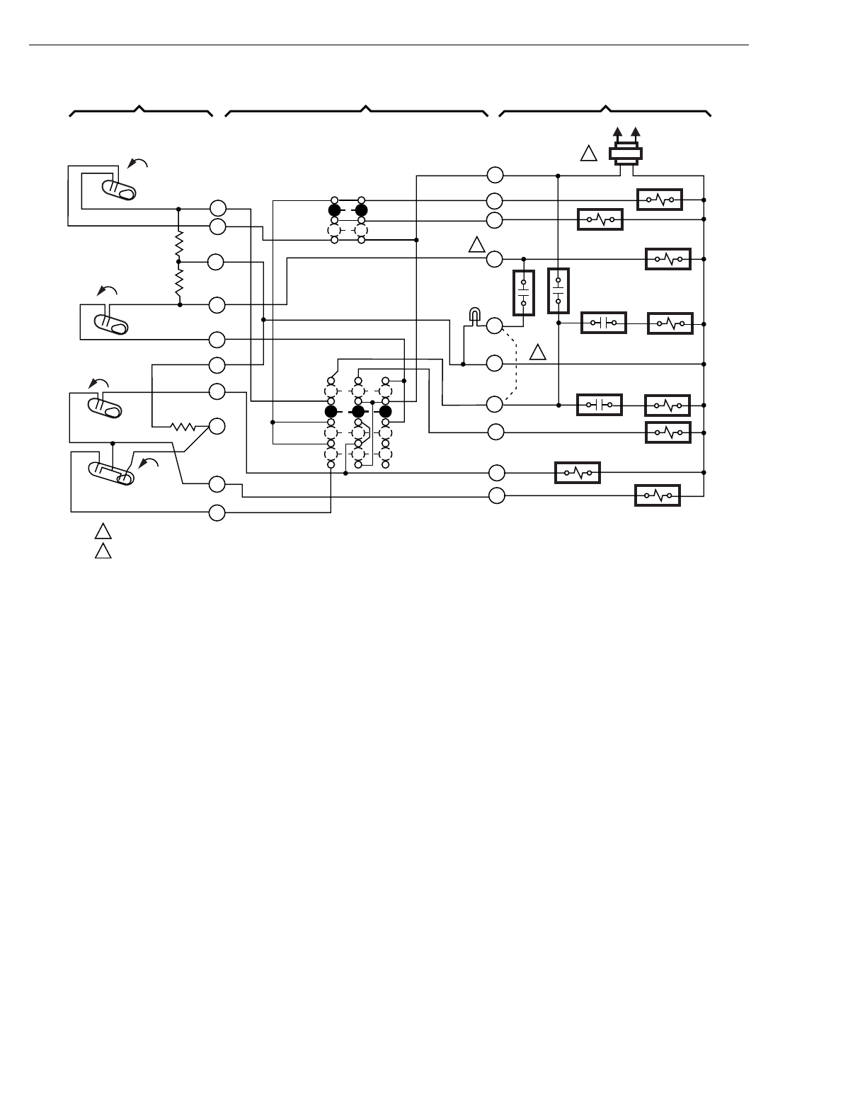
T874 MULTISTAGE THERMOSTATS AND Q674 SUBBASES
60-2485—8144
Fig. 124. Schematic and hookup of T874J with Q674L. Used in heat pump applications.
H1
FALL
C1 RISE
CO
H2
FALL
CO
RISE
L1
(HOT) L2
1
THERMOSTAT SUBBASE SYSTEM COMPONENTS
COMPRESSOR CONTACTOR
FAN RELAY HEAT RELAY 1
OUTDOOR
THERMOSTAT
HEAT RELAY
CONTACT 1 HEAT RELAY 2
HEAT RELAY
CONTACT 2 HEAT RELAY 3
"X" RELAY
"P" RELAY
COOL
CHANGEOVER VALVE
SYSTEM
SWITCH
EM. HT. OR
SUPL. HT.
HEAT
OFF
FAN
SWITCH
AUTO
ON
H1
ANTICIPATOR
H2
ANTICIPATOR
C1 ANTICIPATOR
POWER SUPPLY. PROVIDE DISCONNECT MEANS AND OVERLOAD PROTECTION AS REQUIRED.
ON MODELS INCLUDING EXTERNAL JUMPER, W2=W1 AND L=F.
1
3
4
5
6
8
9
10
11
O
P
X
E
C
L
G
Y
R
2
W2
EM. HT. OR
SUPL. HT.
LED (RED)
M8003
2
COOL
2
12
2
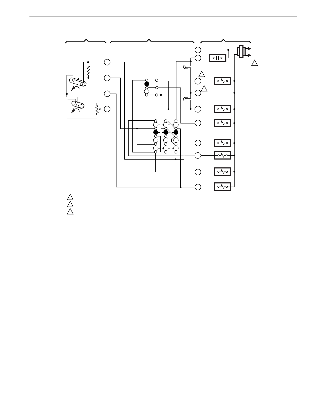
T874 MULTISTAGE THERMOSTATS AND Q674 SUBBASES
145 60-2485—8
Fig. 125. Schematic and hookup of T874R with Q674L. Used in heat pump applications.
L1
(HOT)
L2
1
X
L
W2
EM. HT.
LED (RED)
AUX. HT.
LED (GRN) AUX. HT.
RELAY
FAN RELAY
"B" RELAY
G
COOL CHANGEOVER
VALVE
EM. HT. RELAY
COMPRESSOR
CONTACTOR
O
Y
E
B
SYSTEM
SWITCH
EM. HT.
HEAT
OFF
COOL
H1/C1
ANTICIPATOR
C1
H1
FALL
H2
W3
AUX. HT.
RELAY
H2
ANTICIPATOR
1
2
3
2
3
POWER SUPPLY. PROVIDE DISCONNECT MEANS AND OVERLOAD PROTECTION AS REQUIRED.
TERMINAL LABELED C/X ON SOME MODELS.
W3 TERMINAL AVAILABLE ON SOME MODELS ONLY.
M3683A
AUTO
ON
FAN
SWITCH
FALL
R
2
3
4
6
THERMOSTAT SUBBASE SYSTEM COMPONENTS
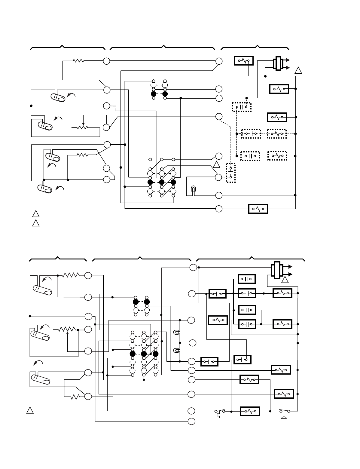
T874 MULTISTAGE THERMOSTATS AND Q674 SUBBASES
60-2485—8146
Fig. 126. Schematic and hookup of T874G with Q674P. Used in heat pump applications.
Fig. 127. Schematic and hookup of T874C with Q674L. Used in heat pump applications.
H2
H1
FALL
CO
RISE
C1 RISE
L1
(HOT)
L2 1
1
2
2
POWER SUPPLY. PROVIDE DISCONNECT MEANS AND OVERLOAD PROTECTION AS REQUIRED.
N.O. SWITCH INSTALLER ADDED, TO LIGHT EM. HT. LED WHEN COMPRESSOR OPERATION IS NOT NORMAL.
THERMOSTAT SUBBASE SYSTEM COMPONENTS
H1 ANTICIPATOR
H2 ANTICIPATOR
C1 ANTICIPATOR
SYSTEM
SWITCH
FAN
SWITCH
AUTO
ON
SUPL. HT.
HEAT
COOL
FAN RELAY
COOL CHANGEOVER
VALVE
COMPRESSOR
CONTACTOR 1
HEAT RELAY 2
HEAT RELAY 1
M4722
1
2
4
6
8
9
10
Y
C
L
E
W2
R
G
O
HEAT RELAY
CONTACT 2
HEAT RELAY
CONTACT 1
HEAT RELAY 3
OUTDOOR
THERMOSTAT
FALL
SUPL. HT.
LED (RED)
FALL
AUTO
ON
H1
HEAT
OFF
COOL
L2
M5652A
POWER SUPPLY. PROVIDE
DISCONNECT MEANS AND
OVERLOAD PROTECTION
AS REQUIRED.
FAN SWITCH
L1
(HOT)
SYSTEM SWITCH
COMPRESSOR
FAILURE
1
1
R
W3
Y
B
L
W2
X
E
FAN RELAY
G
O
LACO CHP
COMPRESSOR
CONTACTOR
EM. HT.
RELAY
COOL CHANGEOVER
VALVE
RD
EM. HT.
LED (RED)
AUX.HT.
LED (GREEN)
RISE
C1
H2
FALL
C1 ANTICIPATOR
EM. HT.
ODT1
RTD1
EHR1
RTD2
ODT2
EHR2 RTD3
RTD1
H2 ANTICIPATOR
H1 ANTICIPATOR
2
3
4
5
6
8
10
THERMOSTAT SUBBASE SYSTEM COMPONENTS
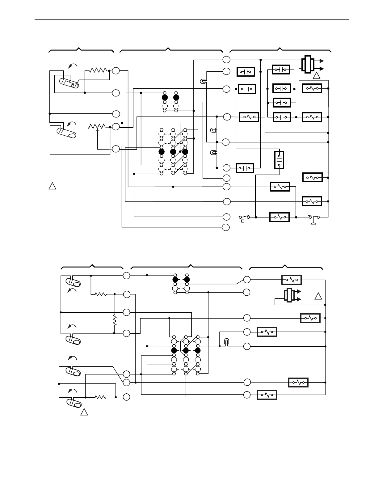
T874 MULTISTAGE THERMOSTATS AND Q674 SUBBASES
147 60-2485—8
Fig. 128. Schematic and hookup of T874R with Q674L. Used in heat pump applications.
Fig. 129. Schematic and hookup of T874G with Q674L. Used in heat pump applications.
FALL
AUTO
ON
H1
HEAT
OFF
COOL
L2
M5653A
POWER SUPPLY. PROVIDE
DISCONNECT MEANS AND
OVERLOAD PROTECTION
AS REQUIRED.
FAN
SWITCH
L1
(HOT)
SYSTEM
SWITCH
SYSTEM
MONITOR
1
1
R
W3
Y
B
L
W2
X
E
FAN RELAY
G
O
LACO CHP
COMPRESSOR
CONTACTOR
EM. HT. RELAY
COOL CHANGEOVER
VALVE
RD
EM. HT.
LED
(YELLOW)
AUX. HT.
LED
(GREEN)
H2
FALL
EM. HT.
RD
RTD1 EHR1
RTD2
ODT2
EHR2 RTD3
RTD1
H1/C1
ANTICIPATOR ODT1
A
SERVICE
LED (RED)
C1
H2 ANTICIPATOR
2
3
4
5
6
THERMOSTAT SUBBASE SYSTEM COMPONENTS
H1
FALL L1
(HOT)
L2 1
H2
FALL
CO
RISE
C1
RISE
H1 ANTICIPATOR
H2 ANTICIPATOR
C1
ANTICIPATOR
POWER SUPPLY. PROVIDE DISCONNECT MEANS AND OVERLOAD PROTECTION AS REQUIRED.
COMPRESSOR
CONTACTOR
M102A
COOL CHANGEOVER VALVE
EM. HT. RELAY AUX. HT. RELAY
FAN RELAY
G
R
W
X
EM. HT.
LED (RED)
B
O
Y
SYSTEM
SWITCH
EM. HT.
HEAT
OFF
COOL
FAN
SWITCH
AUTO
ON
2
3
4
6
8
9
10
1
THERMOSTAT SUBBASE SYSTEM COMPONENTS
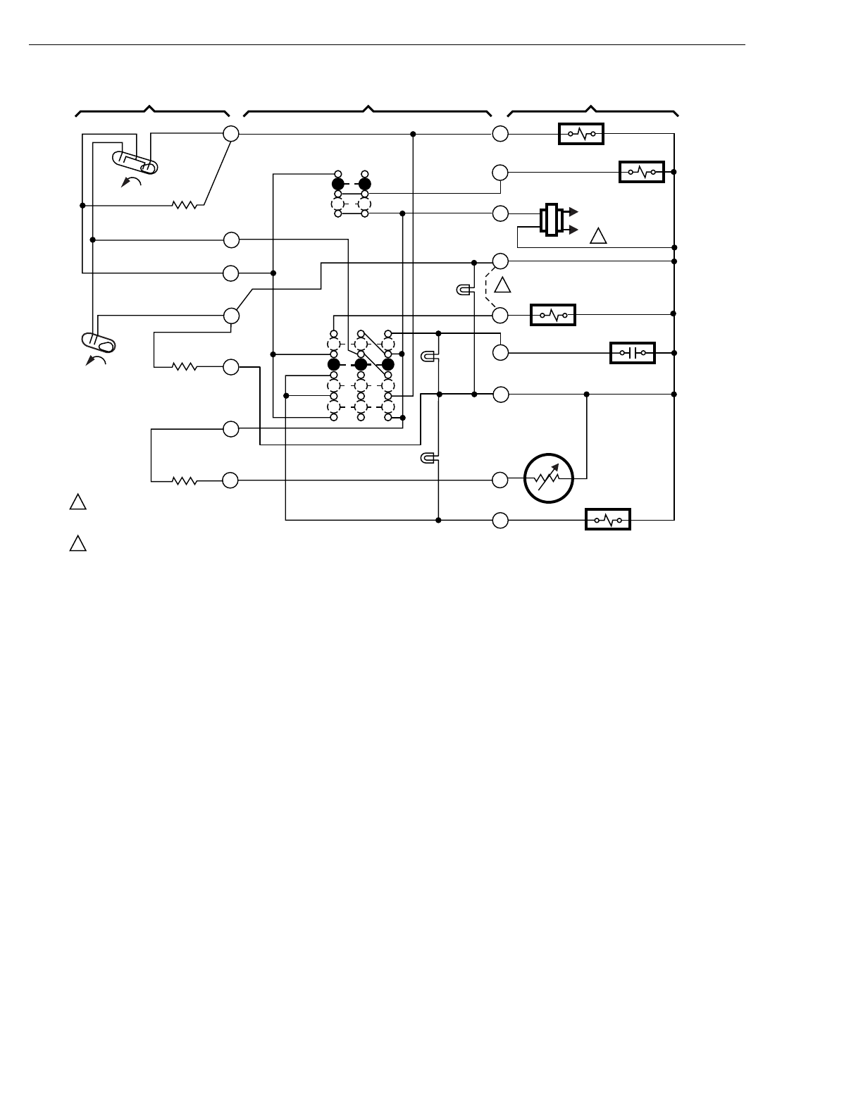
T874 MULTISTAGE THERMOSTATS AND Q674 SUBBASES
60-2485—8148
Fig. 130. Schematic and hookup of T874R with Q674L. Used in heat pump applications.
H2
FALL
H1
FALL
C1
L1
(HOT)
L2 1
2
2
1POWER SUPPLY. PROVIDE DISCONNECT
MEANS AND OVERLOAD PROTECTION
AS REQUIRED.
FACTORY-INSTALLED JUMPER.
THERMOSTAT SUBBASE SYSTEM COMPONENTS
H1/C1
ANTICIPATOR
H2 ANTICIPATOR
SYSTEM
SWITCH
FAN
SWITCH
AUTO
ON
OFF
HEAT
EM. HT.
COOL
FAN RELAY
EM. HT. RELAY
COOL
CHANGEOVER VALVE
COMPRESSOR
CONTACTOR
M1628A
COMPRESSOR
FAILURE
C815A OUTDOOR
THERMISTOR
SYSTEM
LED (GREEN)
CHECK
LED
(RED)
AUX. HT.
LED
(YELLOW)
2
3
4
5
6
11
12
RESET
Y
T
C
X
E
W1
R
G
O
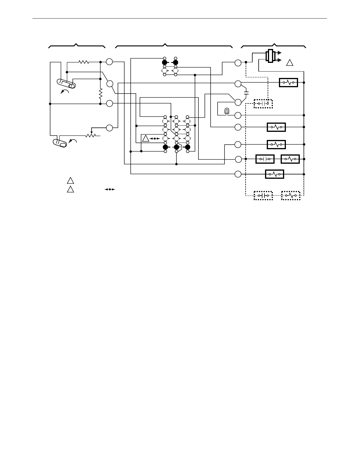
T874 MULTISTAGE THERMOSTATS AND Q674 SUBBASES
149 60-2485—8
Fig. 131. Schematic and hookup of T874R with Q674L. Used in heat pump applications.
H2 FALL
H1
FALL
C1
L1
(HOT)
L2 1
1
2
2
POWER SUPPLY. PROVIDE DISCONNECT MEANS AND OVERLOAD PROTECTION AS REQUIRED.
FOR Q674L1454, IS "OFF".
THERMOSTAT SUBBASE SYSTEM COMPONENTS
H1/C1 ANTICIPATOR
H2 ANTICIPATOR
SYSTEM
SWITCH
FAN
SWITCH
AUTO
ON
SUPL. HT.
HEAT
COOL
COOL CHANGEOVER
VALVE
COMPRESSOR
CONTACTOR
FAN RELAY
M4723
2
3
4
6
R
W2
L
SUPL. HT.
LED (RED)
C
G
O
E
Y
HCR 1 HCR 2
HCR 2 HCR 3
ODT
HCR 1
RESET
HEATER
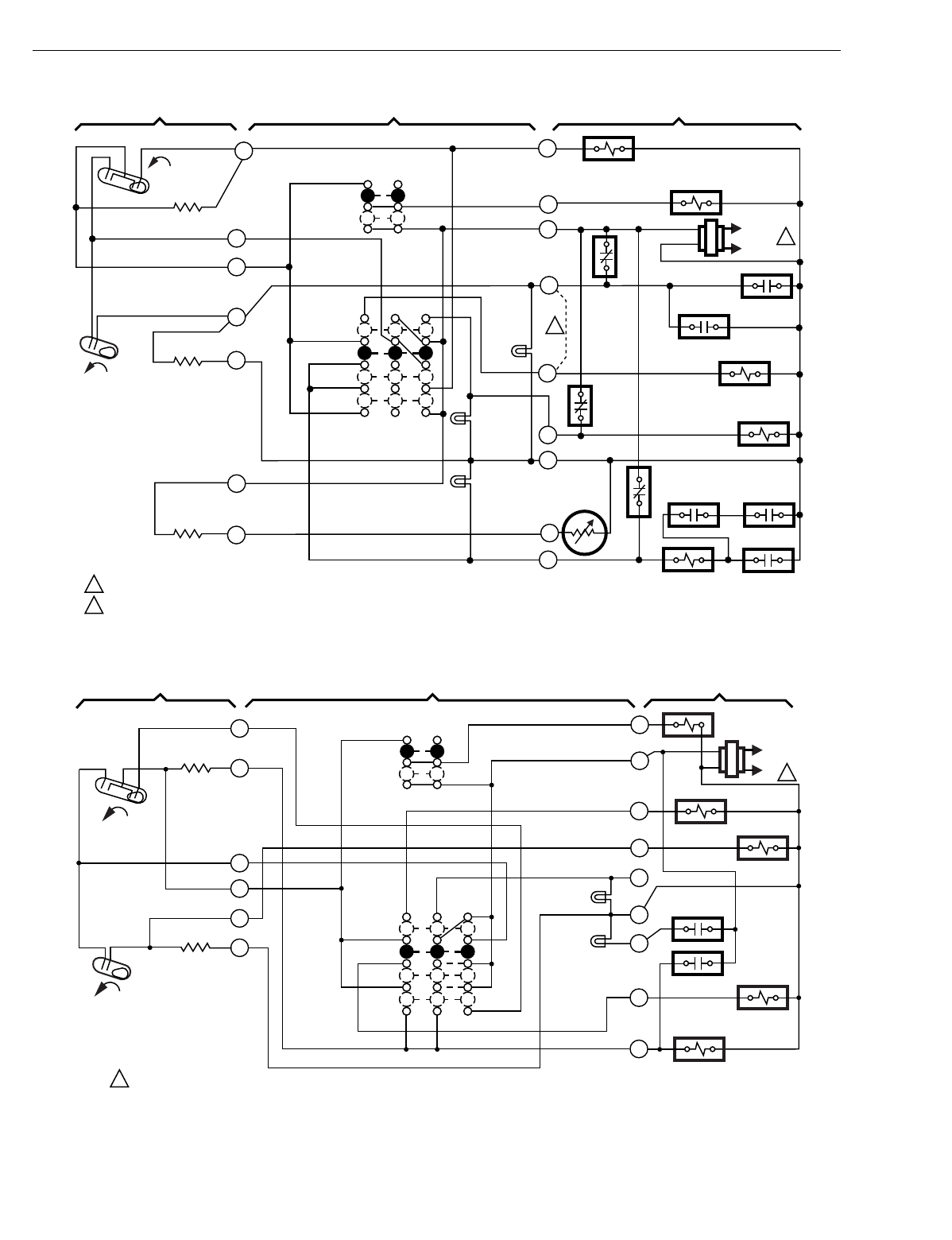
T874 MULTISTAGE THERMOSTATS AND Q674 SUBBASES
60-2485—8150
Fig. 132. Schematic and hookup of T874R with Q674L. Used in heat pump applications.
Fig. 133. Schematic and hookup of T874R with Q674L. Used in heat pump applications.
H2
FALL
H1
FALL
C1
L1
(HOT)
L2
1
1
2
2
POWER SUPPLY. PROVIDE DISCONNECT MEANS AND OVERLOAD PROTECTION AS REQUIRED.
REMOVE JUMPER FOR INDEPENDENT CONTROL OF W1 AND E TERMINALS.
THERMOSTAT SUBBASE SYSTEM COMPONENTS
H1/C1
ANTICIPATOR
H2
ANTICIPATOR
RESET
SYSTEM
SWITCH
FAN
SWITCH
AUTO
ON
OFF
HEAT
EM. HT.
COOL
COMPRESSOR
CONTACTOR
FAN RELAY
M1858
2
3
4
5
6
11
12
Y
T
C
X
E
R
G
O
COOL CHANGEOVER
VALVE
3R
SEQ 1
SEQ 2
EM. HT. RELAY
4R
4R
5R
HPS 4R
4R
C815A
OUTDOOR
THERMISTOR
SYSTEM
LED
(GREEN)
EM. HT.
LED
(RED)
W1
AUX. HT.
LED
(YELLOW)
H2
FALL
H1
FALL
C1
L1
(HOT)
L2 1
G
R
K
W2
L
C
Z
W1
2
3
4
6
POWER SUPPLY. PROVIDE DISCONNECT MEANS AND OVERLOAD
PROTECTION AS REQUIRED.
1
THERMOSTAT SUBBASE SYSTEM COMPONENTS
FAN
SWITCH
AUTO
ON
SYSTEM
SWITCH
EM. HT.
HEAT
OFF
COOL
M2018
H1/C1
ANTICIPATOR
H2 ANTICIPATOR
Y
FAN
RELAY
EM. HT.
RELAY
AUX. HT.
RELAY
CO W1 RELAY
COMPRESSOR
CONTACTOR
1
5
EM. HT.
LED (YEL)
RESET
LED (RED)
COMPRESSOR
FAILURE
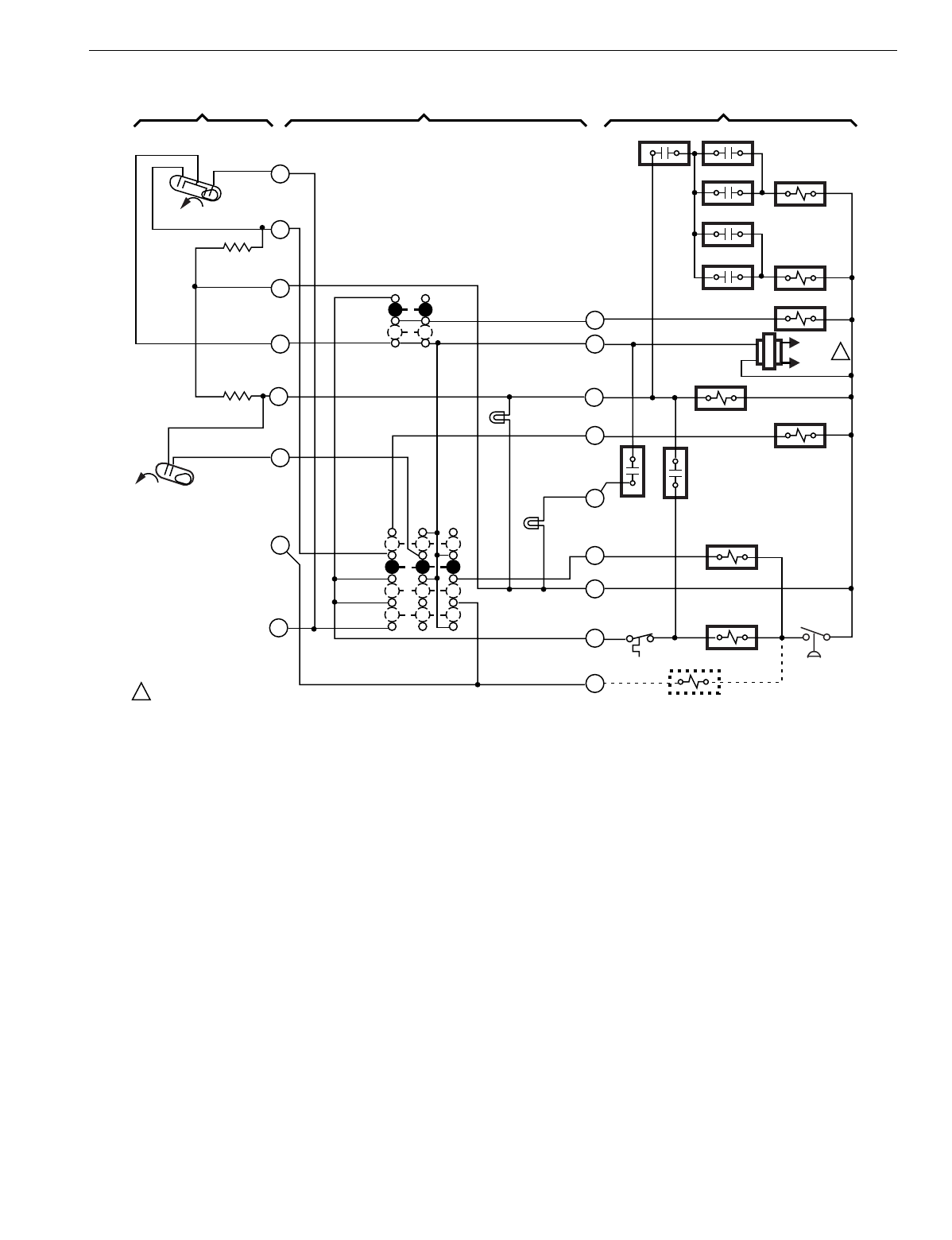
T874 MULTISTAGE THERMOSTATS AND Q674 SUBBASES
151 60-2485—8
Fig. 134. Schematic and hookup of T874R with Q674L. Used in heat pump applications.
H2
FALL
H1
FALL
C1
LACO CHP
POWER SUPPLY. PROVIDE DISCONNECT MEANS
AND OVERLOAD PROTECTION AS REQUIRED.
THERMOSTAT SUBBASE SYSTEM COMPONENTS
L1
(HOT)
L2 1
H1/C1
ANTICIPATOR
H2
ANTICIPATOR
SYSTEM
SWITCH
EM. HT.
HEAT
OFF
COOL
FAN SWITCH
AUTO
ON
AUX. HT.
LED (GREEN)
EM. HT.
LED (RED)
COMP.
FAILURE
CHANGEOVER
VALVE (HEAT)
COMPRESSOR
CONTACTOR
Y
X
B
L
E
W2
R
G
O
6
5
4
3
2
1
EM. HT. RELAY
RD
RTD 1
FAN RELAY
RTD 1 ODT 1
EHR 1 RTD 2
ODT 2
EHR 2 RDT 3
CHANGEOVER VALVE (COOL)
M106A
1
8
10
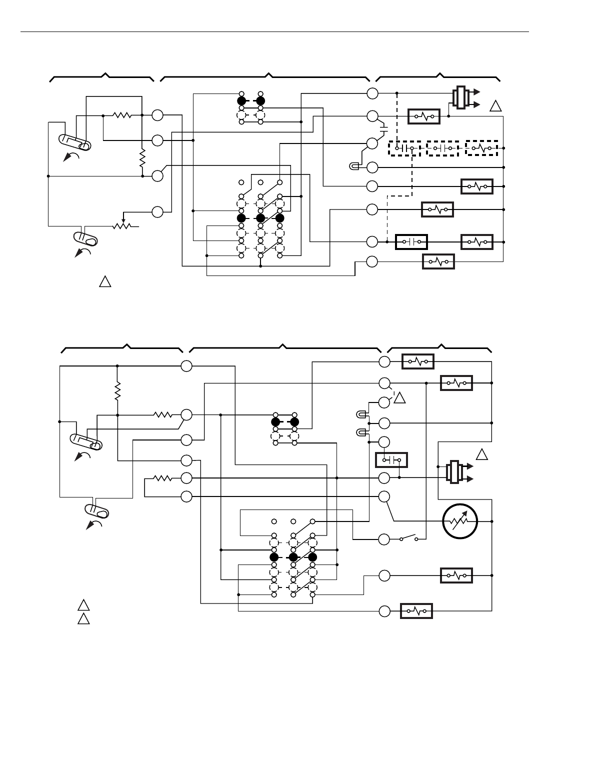
T874 MULTISTAGE THERMOSTATS AND Q674 SUBBASES
60-2485—8152
Fig. 135. Schematic and hookup of T874R with Q674L. Used in heat pump applications.
Fig. 136. Schematic and hookup of T874R with Q674L. Used in heat pump applications.
H2
FALL
H1
FALL
C1
L1
(HOT)
L2 1
R
W2
L
C
G
O
E
Y
2
3
4
6
POWER SUPPLY. PROVIDE DISCONNECT MEANS AND OVERLOAD
PROTECTION AS REQUIRED.
1
THERMOSTAT SUBBASE SYSTEM COMPONENTS
FAN
SWITCH
AUTO
ON
SYSTEM
SWITCH
SUPL. HT.
HEAT
OFF
COOL
M2017
HCR 1
ODT HCR 1 HCR 2
FAN RELAY
COOL
CHANGEOVER VALVE
HCR 2 HCR 3
COMPRESSOR
CONTACTOR
SUPL. HT.
LED (RED)
H1/C1
ANTICIPATOR
RESET
HEATER
H2 ANTICIPATOR
H2
FALL
H1
FALL
C1
L1
(HOT)
L2
1
G
W
U
B
F
R
T
X2
O
Y
2
1
3
4
5
6
FAN RELAY
AUX. HEAT
RELAY
COMP.
FAILURE
O.D.
STAT
C815A OUTDOOR
THERMISTOR
COOL CHANGEOVER
VALVE
COMPRESSOR
CONTACTOR
POWER SUPPLY. PROVIDE DISCONNECT MEANS AND OVERLOAD
PROTECTION AS REQUIRED.
FIELD REMOVABLE JUMPER
1
2
2
THERMOSTAT SUBBASE SYSTEM COMPONENTS
RESET
FAN
SWITCH
AUTO
ON
AUX. HT.
LED (GRN)
EM. HT.
LED (RED)
SYSTEM
SWITCH
EM. HT.
HEAT
OFF
COOL
M2012
C1
ANTICIPATOR
H1
ANTICIPATOR
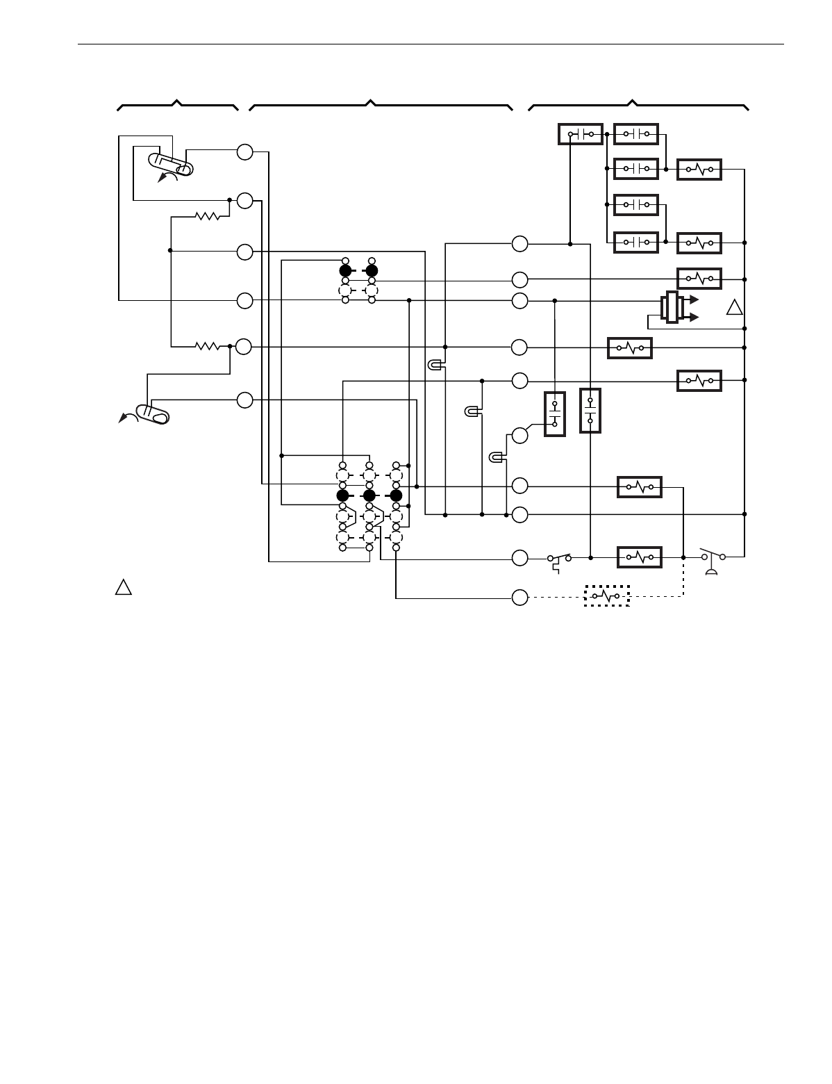
T874 MULTISTAGE THERMOSTATS AND Q674 SUBBASES
153 60-2485—8
Fig. 137. Schematic and hookup of T874R with Q674L. Used in heat pump applications.
H2
FALL
H1
FALL
C1
LACO CHP
POWER SUPPLY. PROVIDE DISCONNECT MEANS
AND OVERLOAD PROTECTION AS REQUIRED.
THERMOSTAT SUBBASE SYSTEM COMPONENTS
L1
(HOT)
L2 1
H1/C1
ANTICIPATOR
H2
ANTICIPATOR
SYSTEM
SWITCH
EM. HT.
HEAT
OFF
COOL
FAN SWITCH
AUTO
ON
AUX. HT.
LED (GREEN)
EM. HT.
LED
(RED)
CHECK
LED (RED)
COMP.
FAILURE
CHANGEOVER
VALVE (HEAT)
COMPRESSOR
CONTACTOR
Y
X
B
L
E
W2
R
G
W3
O
6
5
4
3
2
1
EM. HT. RELAY
RD
RTD 1
FAN RELAY
RTD 1 ODT 1
EHR 1 RTD 2
ODT 2
EHR 2 RDT 3
CHANGEOVER VALVE (COOL)
M105A
1
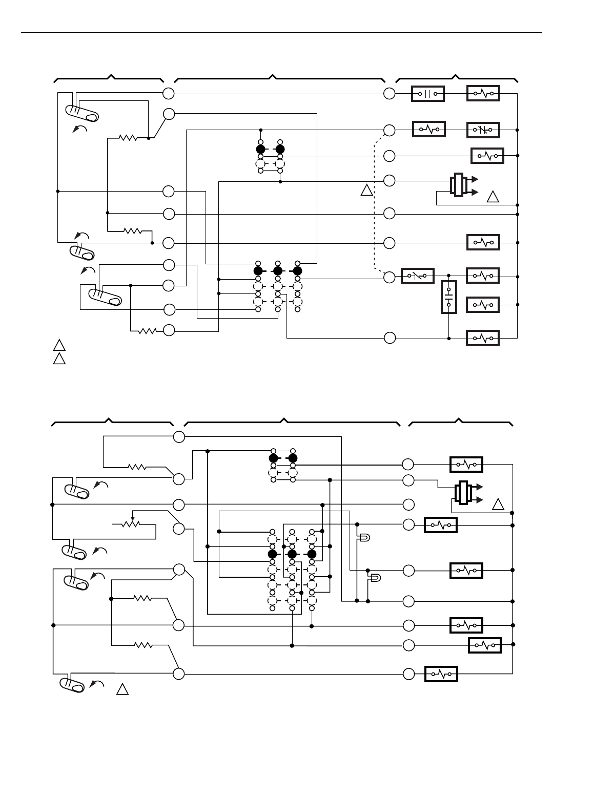
T874 MULTISTAGE THERMOSTATS AND Q674 SUBBASES
60-2485—8154
Fig. 138. Schematic and hookup of T874L with Q674B. Used in heat pump applications.
Fig. 139. Schematic and hookup of T874D with Q674F. Used in heat pump applications.
M103A
R1 NO2 S1 RELAY
S1 NC
SOLIENOID
RELAY FAN RELAY
FAN SWITCH
AUTO
ON
J
S
G
R
C
H2
H1
O
AUX. HT. RELAY
COMPRESSOR
CONTACTOR
R1 NC1
R2 NO1
REVERSING
VALVE
R1 RELAY
SYSTEM SWITCH
HEAT
OFF
COOL
H1 ANTICIPATOR
H2 ANTICIPATOR
C1 ANTICIPATOR
10
9
8
7
5
4
3
2
1
POWER SUPPLY. PROVIDE DISCONNECT MEANS AND OVERLOAD PROTECTION AS REQUIRED.
FIELD REMOVABLE JUMPER
THERMOSTAT SUBBASE SYSTEM COMPONENTS
H2
FALL
H1
FALL
L1
(HOT)
L2 1
RISE
C1
2
2
1
H1 FALL
H2 FALL
C1 RISE
C2 RISE
L1
(HOT)
L2 1
1POWER SUPPLY. PROVIDE DISCONNECT MEANS AND OVERLOAD
PROTECTION AS REQUIRED.
THERMOSTAT SUBBASE SYSTEM COMPONENTS
H1 ANTICIPATOR
H2 ANTICIPATOR
C1 ANTICIPATOR
C2 ANTICIPATOR
SYSTEM
SWITCH
FAN
SWITCH
AUTO
ON
OFF
2 STG. HEAT
HEAT PUMP
AUX. HT.
COOL
FAN RELAY
AUX. HT. RELAY
COOL CHANGEOVER
VALVE
COMPRESSOR
CONTACTOR 1
COMPRESSOR
RELAY
COMPRESSOR
CONTACTOR 2 M4730
HEAT PUMP
LED (GREEN)
AUX. HT
LED (RED)
1
2
4
6
8
10
11 Y2
Y1
C
W2
W1
B
R
G
O
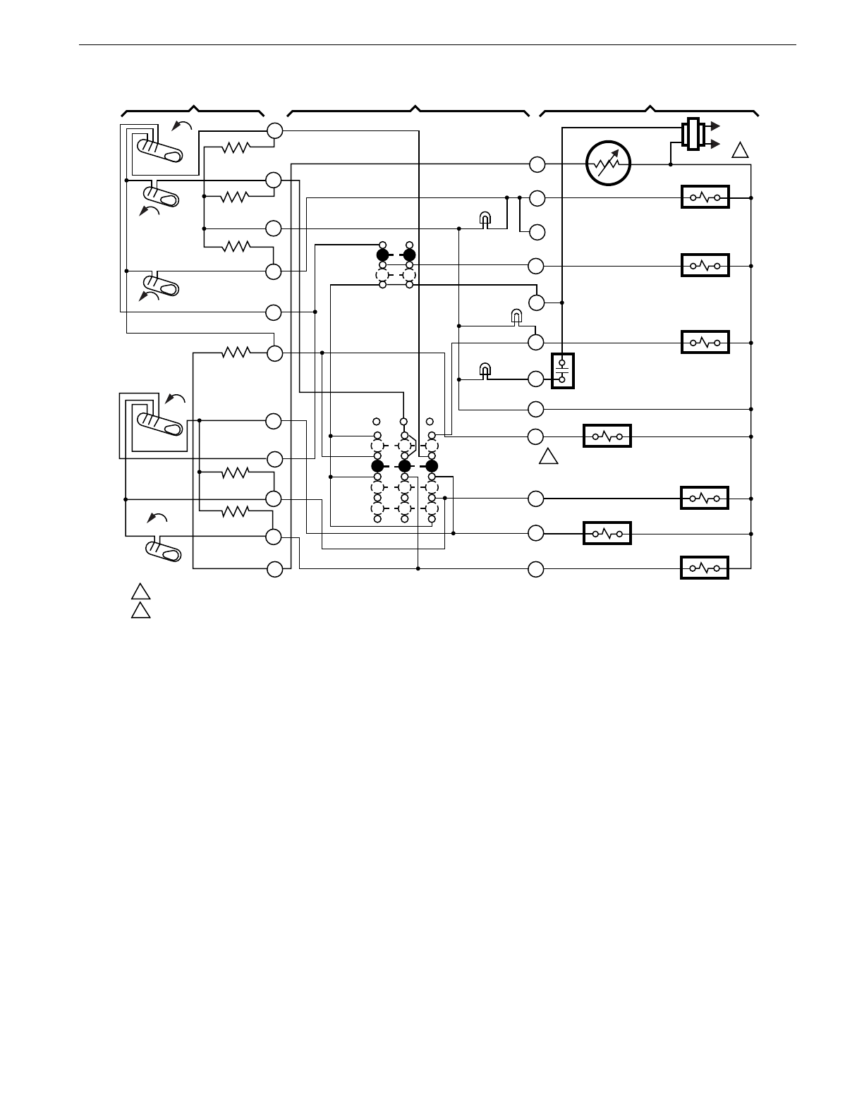
T874 MULTISTAGE THERMOSTATS AND Q674 SUBBASES
155 60-2485—8
Fig. 140. Schematic and hookup of T874W with Q674L. Used in heat pump applications.
1
T
W3
U
G
R
E
L
X
B
O
Y1
Y2
C815A OD THERMISTOR
AUX. HT. RELAY
FAN RELAY
EM. HT. RELAY
COMPRESSOR
MONITOR
HEAT CHANGEOVER
RELAY
COOL CHANGEOVER
RELAY
COMPRESSOR
CONTACTOR 1
COMPRESSOR
CONTACTOR 2
EM.HT.
AUTO
ON
FAN SWITCH
H1 ANTICIPATOR
H2 ANTICIPATOR
H3 ANTICIPATOR
RESET
FALL
FALL
FALL
H1
H3
H2
AUX. HT.
LED
(GREEN)
POWER SUPPLY. PROVIDE DISCONNECT MEANS AND OVERLOAD PROTECTION AS REQUIRED.
CONNECT CHANGEOVER RELAY TO 'O' TERMINAL FOR CHANGEOVER IN COOLING OR TO 'B' TERMINAL FOR CHANGEOVER IN HEATING. M1
56
A
C1 ANTICIPATOR
RISE
RISE C2 ANTICIPATOR
C1
C2
EM. HT.
LED (RED)
CHECK LED
(RED)
HEAT
OFF
COOL
SYSTEM
SWITCH
2
2
THERMOSTAT SUBBASE SYSTEM COMPONENTS
1
2
3
4
5
6
8
9
10
11
12
L1
(HOT)
L2 1
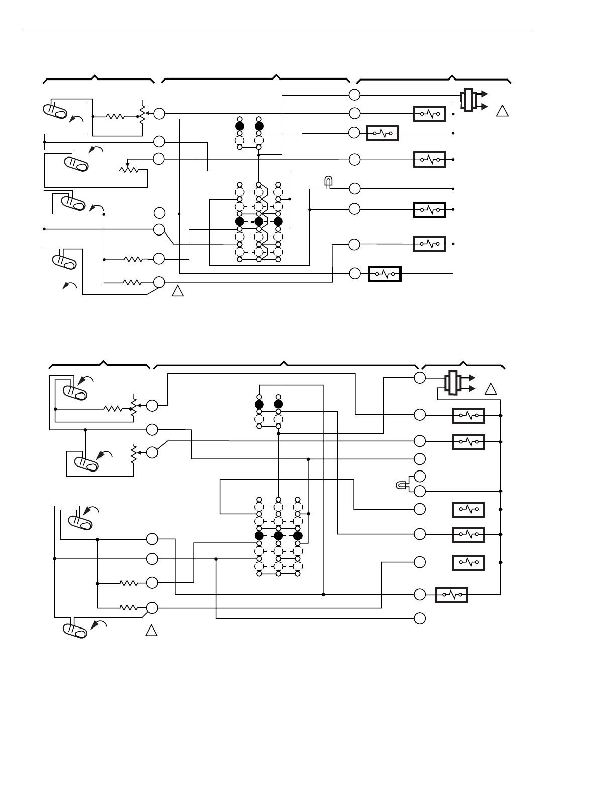
T874 MULTISTAGE THERMOSTATS AND Q674 SUBBASES
60-2485—8156
Fig. 141. Schematic and hookup of T874C with Q674F. Used in standard applications.
Fig. 142. Schematic and hookup of T874C,D with Q674F. Used in standard applications.
H1
FALL
H2
FALL
C1
RISE
L1
(HOT)
L2 1
H1
ANTICIPATOR
4
1
C2
RISE
C1
ANTICIPATOR
C2
ANTICIPATOR
8
9
10
POWER SUPPLY. PROVIDE DISCONNECT MEANS AND
OVERLOAD PROTECTION AS REQUIRED.
1
R
AUTO
ON
FAN
SWITCH
SYSTEM
SWITCH
OFF
EM. HT.
HEAT
AUTO
COOL
HEAT RELAY 1
HEAT RELAY 2
EM. HT. LED
(RED)
EM. HT. RELAY
FAN RELAY
COMPRESSOR
CONTACTOR 1
COMPRESSOR
CONTACTOR 2
M8376
THERMOSTAT SUBBASE SYSTEM COMPONENTS
E
G
Y2
Y1
6
11
X2
W2
W1
H2
ANTICIPATOR
H1
FALL
1
EM. HT.
HEAT
SYSTEM
SWITCH
H1 ANTICIPATOR
H2 ANTICIPATOR
C1
ANTICIPATOR
C2
ANTICIPATOR
AUTO
COOL
W2
M5985
POWER SUPPLY. PROVIDE DISCONECT MEANS AND OVERLOAD PROTECTION AS REQUIRED.
1
SYSTEM COMPONENTSSUBBASE
THERMOSTAT
4
6
8
9
10
11
OFF
AUTO
ON
FAN
SWITCH
L1
(HOT)
L2 1
B
X2
X1
E
G
O
Y2
Y1
R
EM. HT. RELAY
FAN RELAY
COMPRESSOR
CONTACTOR 2
COMPRESSOR
CONTACTOR 1
W1
HEAT RELAY 1
HEAT RELAY 2
C1
C2
RISE
RISE
H2
FALL
CHECK
LED (RED)
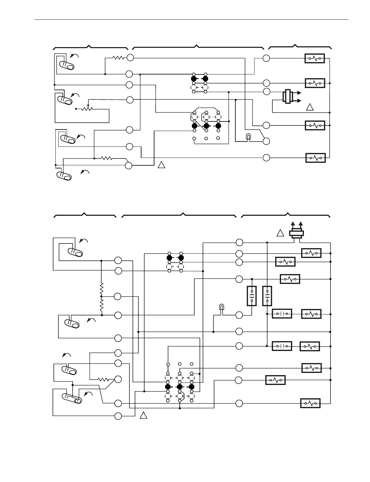
T874 MULTISTAGE THERMOSTATS AND Q674 SUBBASES
157 60-2485—8
Fig. 143. Schematic and hookup of T874G with Q674B. Used in heat pump applications.
Fig. 144. Schematic and hookup of T874J with Q674J. Used in heat pump applications.
THERMOSTAT SUBBASE SYSTEM COMPONENTS
M8378
H1
FALL 1
H1 ANTICIPATOR
2
FAN
SWITCH
AUTO
ON
4
R
COMPRESSOR
CONTACTOR
FAN RELAY
H2
FALL
1POWER SUPPLY. PROVIDE DISCONNECT MEANS AND
OVERLOAD PROTECTION AS REQUIRED.
CO
RISE
H2
ANTICIPATOR
8
L1
(HOT)
1
10
9
C1
RISE
G
AUX. HT. RELAY
L2
W1
C
AUX. HT. LED
(RED)
6
SYSTEM
SWITCH
OFF
AUTO
C1
ANTICIPATOR O
Y1
COOL
CHANGEOVER VALVE
H1
FALL
C1 RISE
CO
H2 FALL
CO
RISE
L1
(HOT) L2
1
THERMOSTAT SUBBASE SYSTEM COMPONENTS
COMPRESSOR CONTACTOR
FAN RELAY
HEAT RELAY 1
OUTDOOR
THERMOSTAT
HEAT RELAY
CONTACT 1 HEAT RELAY 2
HEAT RELAY
CONTACT 2 HEAT RELAY 3
"X" RELAY
"P" RELAY
COOL CHANGEOVER
VALVE
SYSTEM
SWITCH
SUPL. HT.
ON
OFF
FAN
SWITCH
AUTO
ON
H1 ANTICIPATOR
H2 ANTICIPATOR
C1 ANTICIPATOR
POWER SUPPLY. PROVIDE DISCONNECT MEANS AND OVERLOAD PROTECTION AS REQUIRED.
1
3
4
5
6
8
9
10
11 O
P
X
E
C
L
G
Y
R
2
W2
SUPP. HT.
LED (RED)
M5956
12
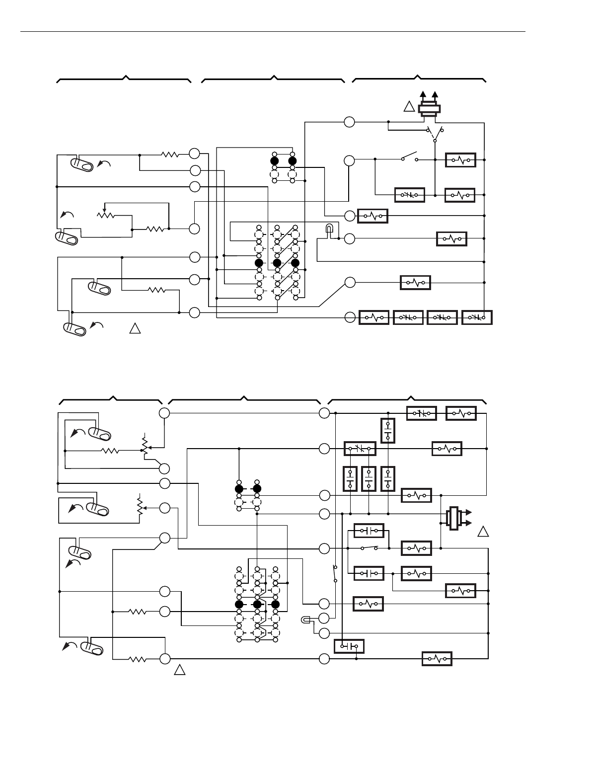
T874 MULTISTAGE THERMOSTATS AND Q674 SUBBASES
60-2485—8158
Fig. 145. Schematic and hookup of T874G with Q674F. Used in heat pump applications.
Fig. 146. Schematic and hookup of T874D with Q674F. Used in heat pump applications.
OFF
COOL
OUTDOOR
THERMOSTAT
ON
SYSTEM
SWITCH
FAN
SWITCH
1POWER SUPPLY. PROVIDE DISCONNECT MEANS AND
OVERLOAD PROTECTION AS REQUIRED.
M8375
EM. HT. RELAY
TIME DELAY
FAN RELAY
4
EM. HT.
LED (RED)
EM. HT.
HEAT
AUTO
SUP. ELEC.
HT. RELAY
DEFROST
RELAY
COMPRESSOR
CONTACTOR INTERNAL
THERMOSTAT
COOL CHANGEOVER
VALVE
HIGH
PRESSURE
SWITCH
OVERLOAD
AUTO
H1
ANTICIPATOR
H2
ANTICIPATOR
C1 ANTICIPATOR
C1 RISE
FALL
EM. HT. RELAY
6
V
9
8
10
CO
FALL
H1
FALL
H2
F
L2 (HOT) L1
1
Y
1
M
E
R
FAN RELAY
THERMOSTAT SUBBASE SYSTEM COMPONENTS
2
H1
FALL
Y1
G
W1
X
W2
R
AUTO
COOL
SYSTEM
SWITCH
H1 ANTICIPATOR
AUTO
ON
FAN
SWITCH
1POWER SUPPLY. PROVIDE DISCONNECT MEANS AND OVERLOAD
PROTECTION AS REQUIRED. M7010
THERMOSTAT SUBBASE SYSTEM COMPONENTS
4
8
9
10
11
H2
ANTICIPATOR
SUPL.
HEAT
LED
(RED)
C
E
1
3
6
SUPL. HT.
HEAT
OFF
Y2
RVR RVR
EHR EHR
COMPRESSOR
CONTACTOR 1
DFR 2
REVERSING
RELAY
FAN RELAY
L1
(HOT)
L2
1
ODT 3
HEAT
RELAY 2
HEAT RELAY 1
ODT 2
HEAT RELAY 3
SUPL. HT.
RELAY
DFR 2 COMPRESSOR
CONTACTOR 2
LPCO
H2
FALL
C1
RISE
C1
ANTICIPATOR
C2
ANTICIPATOR
RISE C2
EHT
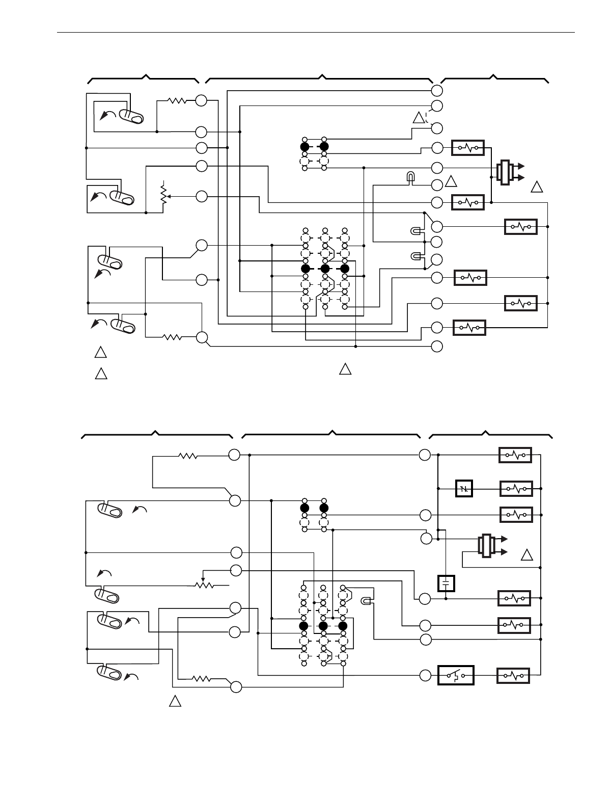
T874 MULTISTAGE THERMOSTATS AND Q674 SUBBASES
159 60-2485—8
Fig. 147. Schematic and hookup of T874G with Q674F. Used in heat pump applications.
Fig. 148. Schematic and hookup of T874G with Q674F. Used in heat pump applications.
H1
FALL
1
G
A
X
W2
R
AUTO
COOL
SYSTEM
SWITCH
H1
ANTICIPATOR
AUTO
ON
FAN
SWITCH
1POWER SUPPLY. PROVIDE DISCONNECT MEANS AND OVERLOAD
PROTECTION AS REQUIRED.
CONNECT TO Y OR W TERMINAL WITH FACTORY INSTALLED JUMPER. M7024
THERMOSTAT SUBBASE SYSTEM COMPONENTS
4
8
9
10
H2
ANTICIPATOR
O
L
2
3
6
EM. HT.
HEAT
OFF
Y
H2
FALL
CO
RISE
C1
ANTICIPATOR
RISE C1
L1
(HOT)
L2
1
2
S
W3
E
T
MODE SIGNAL
COOL
CHANGEOVER
VALVE
COMPRESSOR
CONTACTOR
EM. HT. RELAY
HEAT RELAY 1 HEAT RELAY 2
FAN RELAY
MODE SIGNAL
5
AUX. HT.
LED (GRN)
EM. HT.
LED (YEL)
SERVICE
LED (RED)
2
2
3JUMPER FACTORY INSTALLED.
3
OFF
COOL
DEFROST
RELAY
FAN
SWITCH
ON
SYSTEM
SWITCH
1POWER SUPPLY. PROVIDE DISCONNECT MEANS AND OVERLOAD PROTECTION AS REQUIRED. M8382
AUX. HT. RELAY
EM. HT. RELAY
4
EM. HT.
LED
(RED)
EM. HT.
HEAT
AUTO
COOL CHANGEOVER
VALVE
BLOWER SPEED
RELAY
DEFROST
RELAY
BLOWER RELAY
COOL
CONTRACTOR
LOCKOUT
THERMOSTAT
AUTO
E
H1 ANTICIPATOR
H2 ANTICIPATOR
C1
ANTICIPATOR
C1 RISE
RISE
6
O
8
10
R
CO
FALL
H1
FALL
H2 W2
L1
(HOT)
L2 1
G
1
Y
C
THERMOSTAT SUBBASE SYSTEM COMPONENTS
9
2
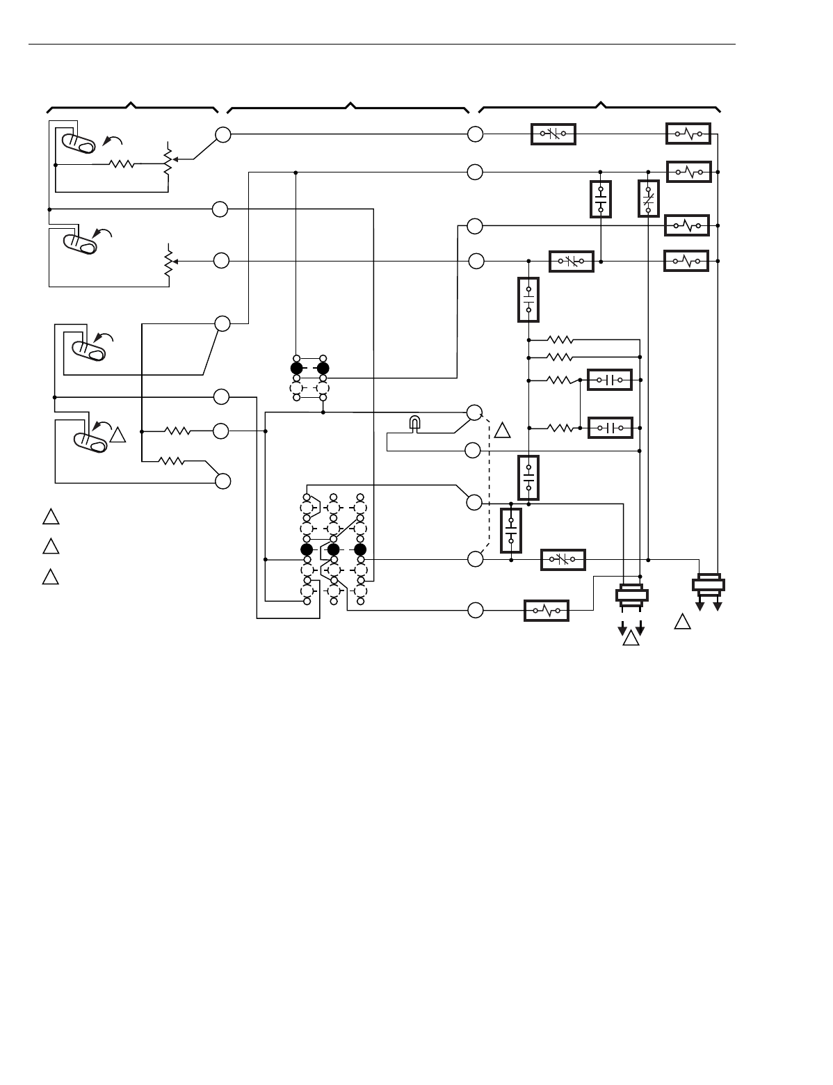
T874 MULTISTAGE THERMOSTATS AND Q674 SUBBASES
60-2485—8160
Fig. 149. Schematic and hookup of T874C with Q674F. Used in heat pump applications.
THERMOSTAT SUBBASE SYSTEM COMPONENTS
H1
FALL
H1 ANTICIPATOR
1
H2
FALL
H2
ANTICIPATOR
W1
EMR4 2R
1R
5R
3R
Y1
G
EMR4
EMR2
THERMAL SWITCHES
FOR HEATING
ELEMENTS HTR 1
C1
RISE
HTR 3
HTR 2
OUTDOOR
THERMOSTAT
EMR3
L1
(HOT)
L2
1
L1
(HOT) L2
1
C2
RISE
8
3
C1
ANTICIPATOR
C2
ANTICIPATOR
9
11
10
EM. HT. LED
RC
X1
RH
EMR1
EMR1
Z
EM. HT. RELAY
2
1
2
3
POWER SUPPLY. PROVIDE DISCONNECT MEANS
AND OVERLOAD PROTECTION AS REQUIRED.
OPTIONAL FIELD WIRE JUMPER TO ALLOW
SINGLE SYSTEM TRANSFORMER.
FOR Q674F1048, DELETE C2 STAGE.
M8380
SYSTEM
SWITCH
OFF
EM. HT.
HEAT
AUTO
COOL
E
FAN
SWITCH
AUTO
ON
W2
6
4
3R1
4R2 2R2
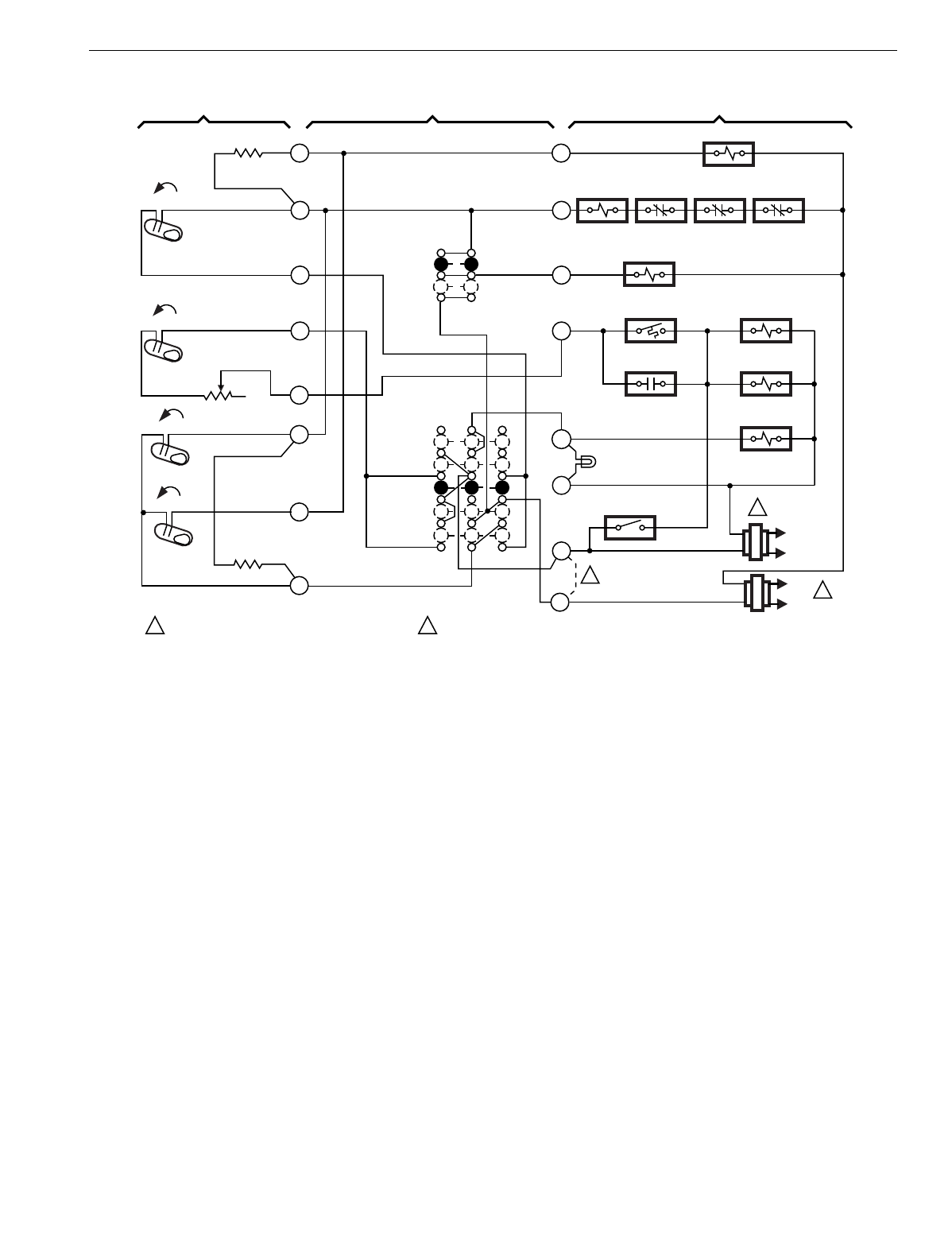
T874 MULTISTAGE THERMOSTATS AND Q674 SUBBASES
161 60-2485—8
Fig. 150. Schematic and hookup of T874G with Q674F. Used in heat pump applications.
L1
HOT
L2
1
F
EM. HEAT
LED (RED)
V
SYSTEM
SWITCH
EM. HT.
HEAT
OFF
COOL
H1 ANTICIPATOR
1POWER SUPPLY. PROVIDE DISCONNECT MEANS
AND OVERLOAD PROTECTION AS REQUIRED. M2852A
R
H1
FALL
E
AUTO
ON
FAN SWITCH
VR
Y
M
OUTDOOR
THERMOSTAT SUPL. ELEC.
HT. RELAY
X
COOL CHANGEOVER VALVE
COMPRESSOR
CONTACTOR
OVERLOAD
SWITCH
INTERNAL
THERMOSTAT
HI PRESSURE
SWITCH
FAN
RELAY
EM. HT. RELAY
CONTACT TIME DELAY
FAN RELAY
TIME DELAY
FAN RELAY
SYSTEM
MONITOR
AUTO
H2
FALL
H2 ANTICIPATOR
CO
RISE
C1
RISE
C1
ANTICIPATOR
REMOVE FACTORY INSTALLED V-VR JUMPER WHEN CONNECTING
A TWO TRANSFORMER SYSTEM.
2
2
L1
HOT
L2 1
1
2
3
5
6
8
9
10
THERMOSTAT SUBBASE SYSTEM COMPONENTS
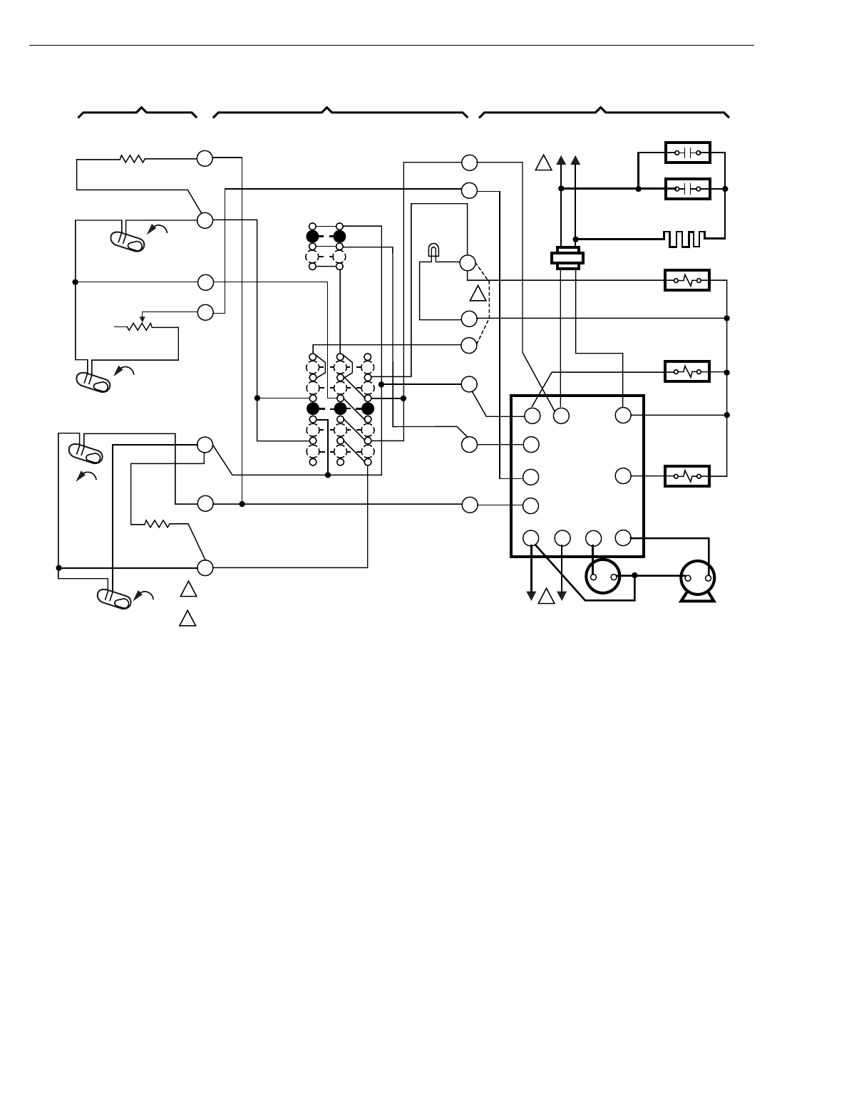
T874 MULTISTAGE THERMOSTATS AND Q674 SUBBASES
60-2485—8162
Fig. 151. Schematic and hookup of T874G with Q674F. Used in heat pump applications.
H1 FALL
H2 FALL
CO
RISE
C1 RISE
L1
(HOT)
L2
1
1
2
1
L1
(HOT) L2
2
POWER SUPPLY. PROVIDE DISCONNECT MEANS AND OVERLOAD
PROTECTION AS REQUIRED.
OPTIONAL FIELD WIRE JUMPER TO CYCLE W2 WITH H1 IN EM. HT.
(FASTER RESPONSE).
THERMOSTAT SUBBASE SYSTEM COMPONENTS
M4710
H1
ANTICIPATOR
H2
ANTICIPATOR
C1
ANTICIPATOR
SYSTEM
SWITCH
FAN
SWITCH
AUTO
ON
OFF
HEAT
EM. HT.
AUTO
COOL
EM. HT.
LED
(RED)
EM. HT. RELAY
CONTACT 1
T6031 REFRIGERATON/
TEMPERATURE
CONTROLLER
EM. HT.
EM. HT. RELAY
COMPRESSOR
CONTACTOR
SEQUENTIAL
RELAY
FANREVERSING
SOLENOID
COM
EM.
HT.
FAN
R8233B
YR
G
W
O
CDF
RS
O
G
Y
H
X
W2
R
1
2
4
6
8
9
10
E
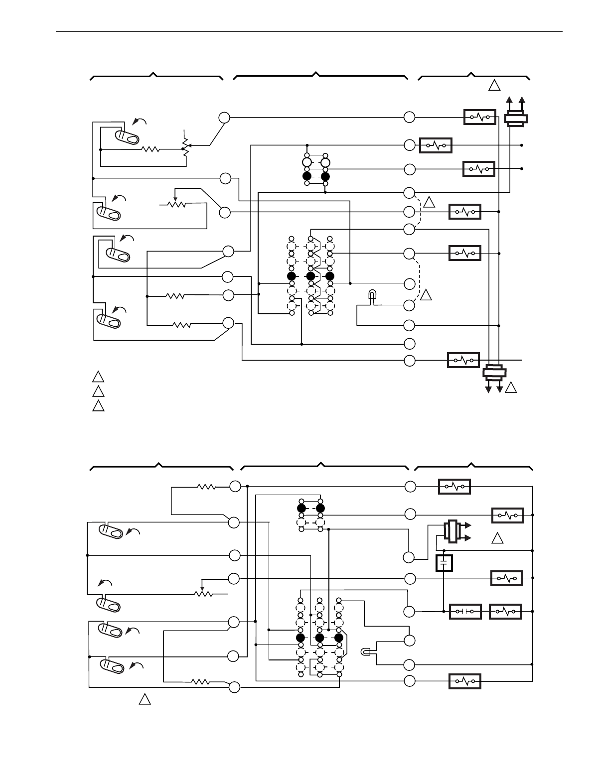
T874 MULTISTAGE THERMOSTATS AND Q674 SUBBASES
163 60-2485—8
Fig. 152. Schematic and hookup of T874D with Q674F. Used in standard applications.
Fig. 153. Schematic and hookup of T874G with Q674F. Used in heat pump applications.
OFF
ON
SYSTEM
SWITCH
FAN SWITCH
1
2
3
POWER SUPPLY. PROVIDE DISCONNECT MEANS AND OVERLOAD PROTECTION AS REQUIRED.
M8377
HEAT RELAY 2
COMPRESSOR
CONTRACTOR 1
EM. HEAT
LED (RED)
EM. HT.
HEAT
AUTO
HEAT RELAY
COMPRESSOR
CONTRACTOR 2
AUTO
H1 ANTICIPATOR
H2 ANTICIPATOR
C2 ANTICIPATOR
C1
RISE
RISE
W1
FALL
H1
FALL
H2
RC
Y1
G
1
Y2
X2
O
B
X1
E
RH
FAN RELAY
EM. HT. RELAY
L1
(HOT)
L2
1
L1
(HOT)
L2
1
2FACTORY SUPPLIED FIELD INSTALLED JUMPER TO E-X2 FOR CONSTANT POWER TO EM HT LIGHT IN EM HT POSITION.
3OPTIONAL FIELDWARE JUMPER TO ALLOW SINGLE SYSTEM TRANSFORMER.
6
C1 ANTICIPATOR
C2
11
10
W2
8
THERMOSTAT SUBBASE SYSTEM COMPONENTS
COOL
9
4
OFF
COOL
OUTDOOR
THERMOSTAT
FAN
SWITCH
ON
SYSTEM
SWITCH
1POWER SUPPLY. PROVIDE DISCONNECT MEANS AND OVERLOAD PROTECTION AS REQUIRED. M8381
AUX. HT. RELAY
CONTACT
AUX. HT. RELAY
4
EM. HT. LED
(RED)
EM. HT.
HEAT
AUTO
COOL CHANGEOVER
VALVE
FAN RELAY
COMPRESSOR
CONTACTOR
AUTO
H1
ANTICIPATOR
H2 ANTICIPATOR
C1 ANTICIPATOR
C1 RISE
RISE
EM. HT.
RELAY
6
O
9
10
R
CO
FALL
H1
FALL
H2
W2
L1
(HOT)
L2 1
G
1
2
E
X
THERMOSTAT SUBBASE SYSTEM COMPONENTS
8
Y
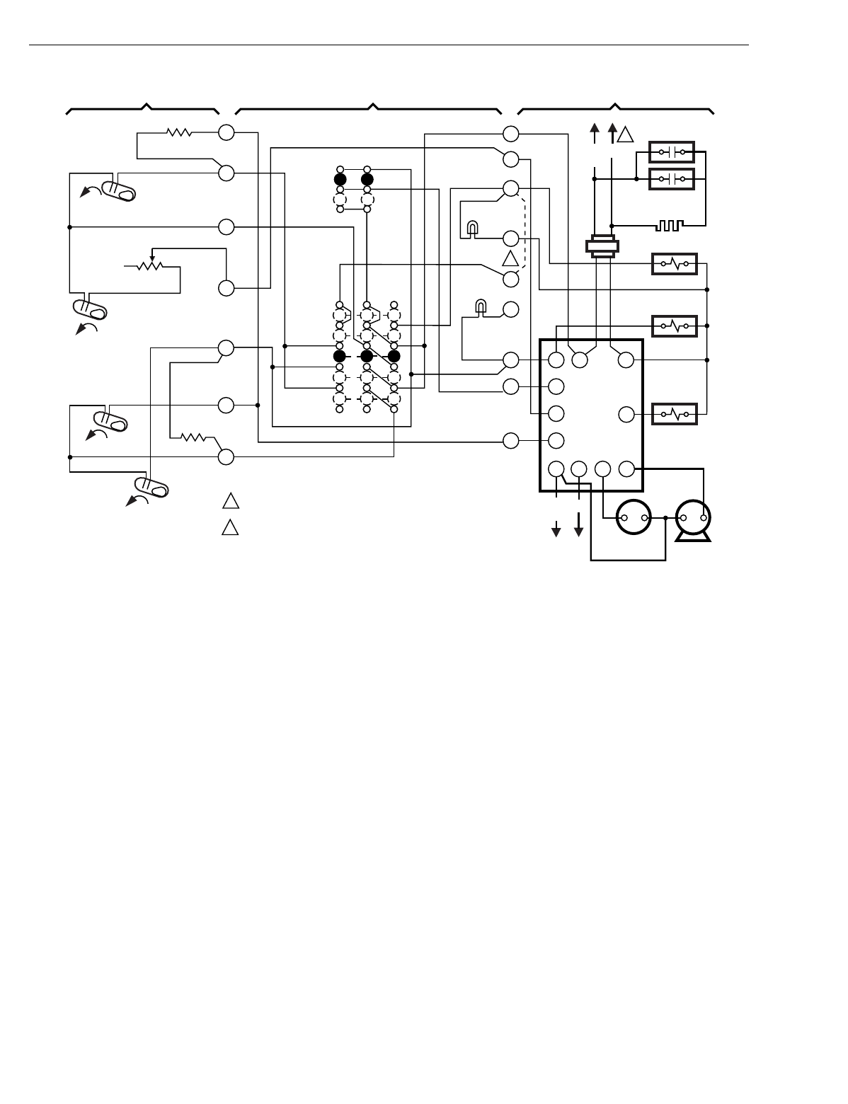
T874 MULTISTAGE THERMOSTATS AND Q674 SUBBASES
60-2485—8164
Fig. 154. Schematic and hookup of T874G with Q674F. Used in heat pump applications.
H2
FALL
YR
COM
G
W
O
EH
O
G
Y
A
H
E
W2
R1
COMPRESSOR
CONTACTOR
EM. HT.
HEAT
AUTO
COOL
COMP. FAULT
LED (YELLOW)
SYSTEM
SWITCH
FAN
SWITCH
AUTO
ON
1 POWER SUPPLY. PROVIDE DISCONNECT MEANS AND
OVERLOAD PROTECTION AS REQUIRED.
OPTIONAL FIELD WIRE JUMPER TO CYCLE W2 WITH H1
IN EM. HEAT(FASTER RESPONSE).
2
H2 ANTICIPATOR
2
X
CDF RS
FAN
L1
(HOT) L2
EM. HT. RELAY
FAN
REVERSING
SOLENOID
T6031
REFRIGERATION
TEMPERATURE
CONTROLLER
EM. HT. RELAY
CONTACT 1
EM. HT.
L1
(HOT)L2
EM. HT.
LED (RED)
H1 ANTICIPATOR
H1
FALL
H1 ANTICIPATOR
CO
RISE
C1
RISE
SEQUENTIAL
RELAY
M2858
R8233B
THERMOSTAT SUBBASE SYSTEM COMPONENTS
1
2
6
4
8
9
10
OFF
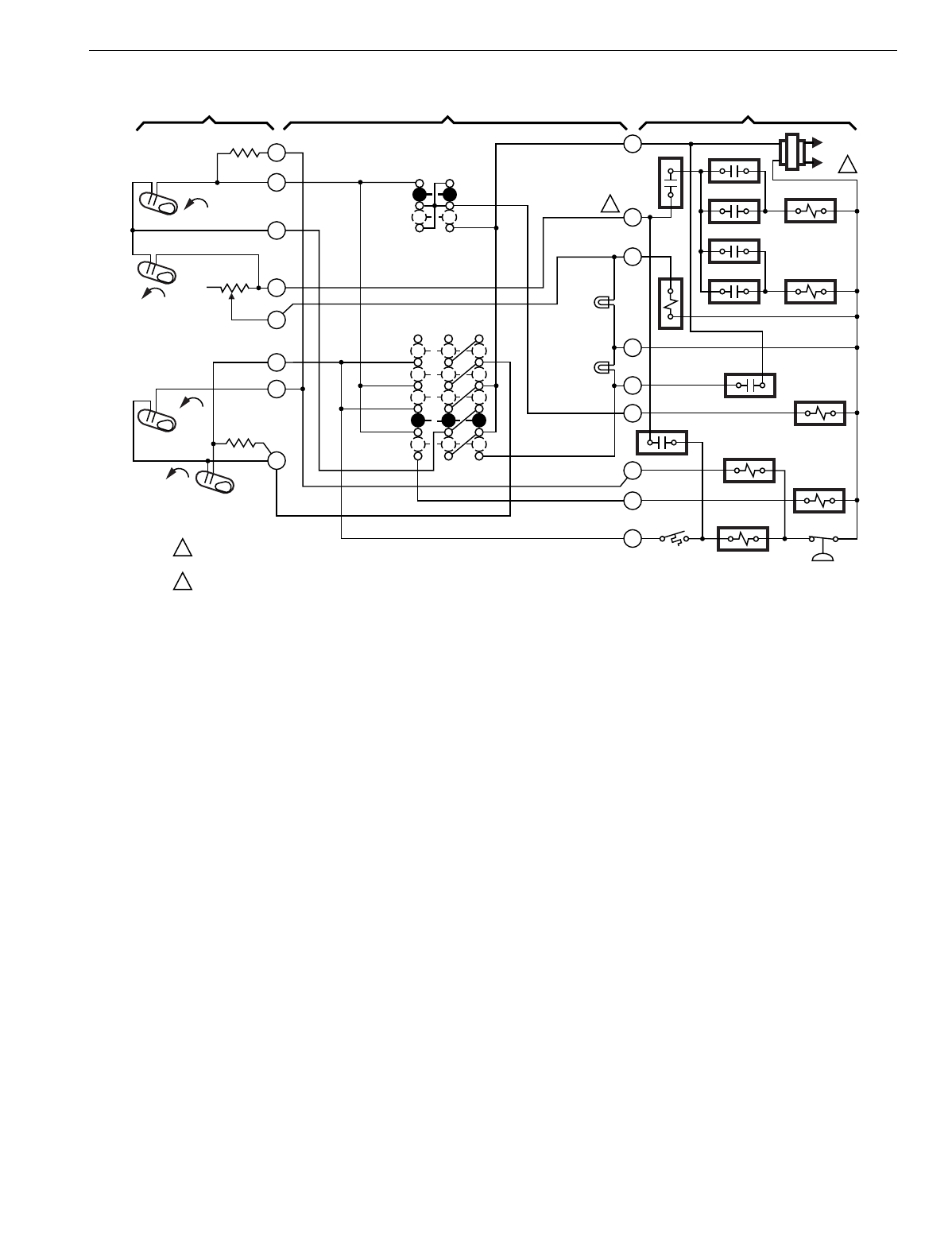
T874 MULTISTAGE THERMOSTATS AND Q674 SUBBASES
165 60-2485—8
Fig. 155. Schematic and hookup of T874G with Q674F. Used in heat pump applications.
H2
FALL
L1
(HOT)
L2 1
R
W3
W2
X
L
G
O
E
Y
RTD1 OTD1
EHR1
ODT2
EHR2
RTD2
RTD3
RTD1
SYSTEM
MONITOR
FAN
RELAY
RD
COOL
CHANGEOVER VALVE
EM. HT.
RELAY
LACO
COMPRESSOR
CONTACTOR CHP
2
3
4
5
6
8
9
10
H1 FALL
H1 ANTICIPATOR
H2
ANTICIPATOR
CHANGEOVER
RISE
C1
RISE
C1
ANTICIPATOR
OFF
COOL
AUTO
HEAT
EM. HT.
SYSTEM
SWITCH
AUTO
ON
FAN
SWITCH
AUX. HT.
LED (GRN)
EM. HT.
LED (RED)
POWER SUPPLY. PROVIDE DISCONNECT MEANS AND OVERLOAD
PROTECTION AS REQUIRED.
W3 TERMINAL ON SELECT MODELS.
1
2
2
M1589
THERMOSTAT SUBBASE SYSTEM COMPONENTS
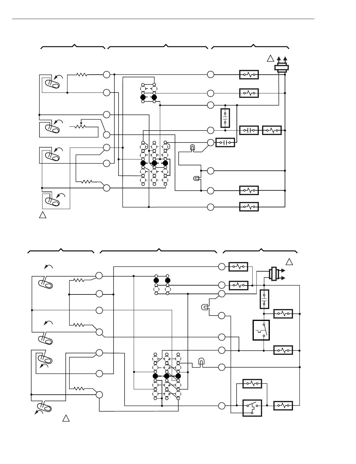
T874 MULTISTAGE THERMOSTATS AND Q674 SUBBASES
60-2485—8166
Fig. 156. Schematic and hookup of T874G with Q674F. Used in heat pump applications.
Fig. 157. Schematic and hookup of T874G with Q674F. Used in heat pump applications.
COMPRESSOR
FAILURE
H1
FALL
H2
FALL
L1
(HOT)L2
1
CO
RISE
H1
ANTICIPATOR
1
2
4
6
9
8
C1
RISE
OFF
EM. HT.
SYSTEM
SWITCH
FAN
SWITCH
10
C1 ANTICIPATOR
H2 ANTICIPATOR
HEAT
AUTO
COOL
ON
ON
EM. HT. LED
(RED)
L1
E
AUX. HT.
RELAY
CONTACT EM. HT.
RELAY
R
G
O
COOL
CHANGEOVER VALVE
FAN RELAY
OUTDOOR
THERMOSTAT
EM. HT. LED
(GREEN)
X
AUX. HT. RELAY
COMPRESSOR CONTACTOR
W2
Y
M5720
POWER SUPPLY. PROVIDE DISCONNECT MEANS AND OVERLOAD PROTECTION AS REQUIRED.
1
SYSTEM COMPONENTSSUBBASETHERMOSTAT
L2
1
COMPRESSOR
CONTACTOR
H2 ANTICIPATOR
M2860
AUTO
ON
FAN SWITCH
W1
C1
E
W2
H1 ANTICIPATOR
C1 ANTICIPATOR
CO
RISE
C1
FALL
H2
FALL
H1
R
X
Y1
SYSTEM
SWITCH
EM. HT.
HEAT
OFF
COOL
AUTO
G
TIME DELAY
RELAY 2
FAN RELAY
COOL CHANGEOVER
VALVE
LOCKOUT
RELAY
HI PRESSURE
SWITCH
EM. HT.
LED (RED)
CHECK LED
(GREEN)
TIME DELAY
RELAY 1
DEFROST
RELAY
1POWER SUPPLY. PROVIDE DISCONNECT MEANS AND OVERLOAD PROTECTION AS REQUIRED.
L1
(HOT)
RISE
2
3
4
6
8
9
10
THERMOSTAT SUBBASE SYSTEM COMPONENTS
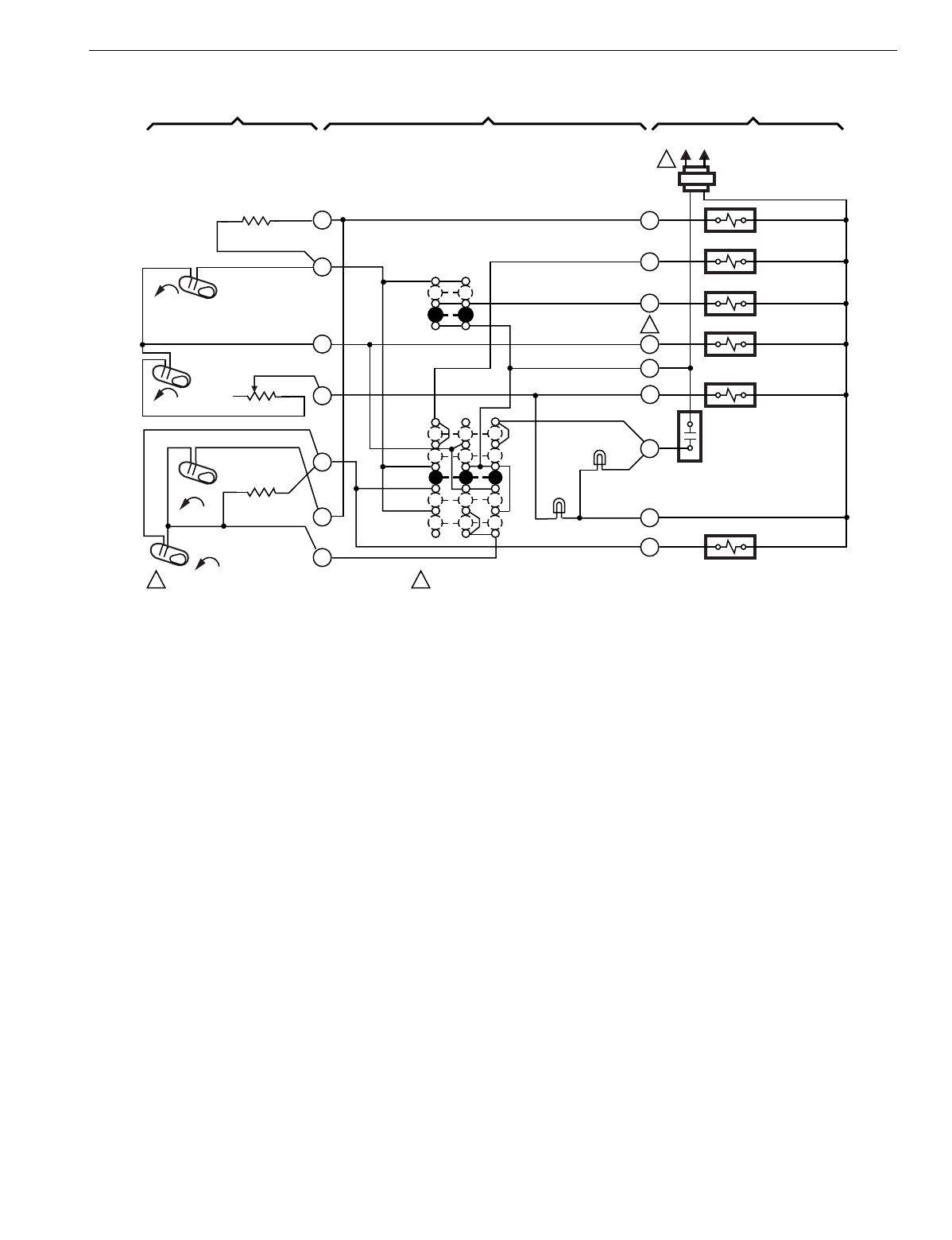
T874 MULTISTAGE THERMOSTATS AND Q674 SUBBASES
167 60-2485—8
Fig. 158. Schematic and hookup of T874G with Q674F. Used in heat pump applications.
4
OFF
EM. HT.
SYSTEM
SWITCH
HEAT
AUTO
COOL AUX. HT. LED (GREEN)
1
X
M5721
8
C1 ANTICIPATOR
POWER SUPPLY. PROVIDE DISCONNECT MEANS
AND OVERLOAD PROTECTION AS REQUIRED.
1
CO
RISE
FALL
H2
6
9
C1 RISE
H2 ANTICIPATOR
10
FALL
H1
H1 ANTICIPATOR
1
2
AUTO
ON
FAN
SWITCH
EM. HT. LED
(RED)
W2
L1
(HOT) L2
1
AUX. HT. RELAY
Y
COMPRESSOR CONTACTOR
2
B TERMINAL ON SELECT MODELS.
R
B
HEAT CHANGEOVER VALVE
G
FAN RELAY
E
EM. HT. RELAY
O
COOL CHANGEOVER VALVE
COMPRESSOR
FAILURE
2
L
SYSTEM COMPONENTSSUBBASETHERMOSTAT
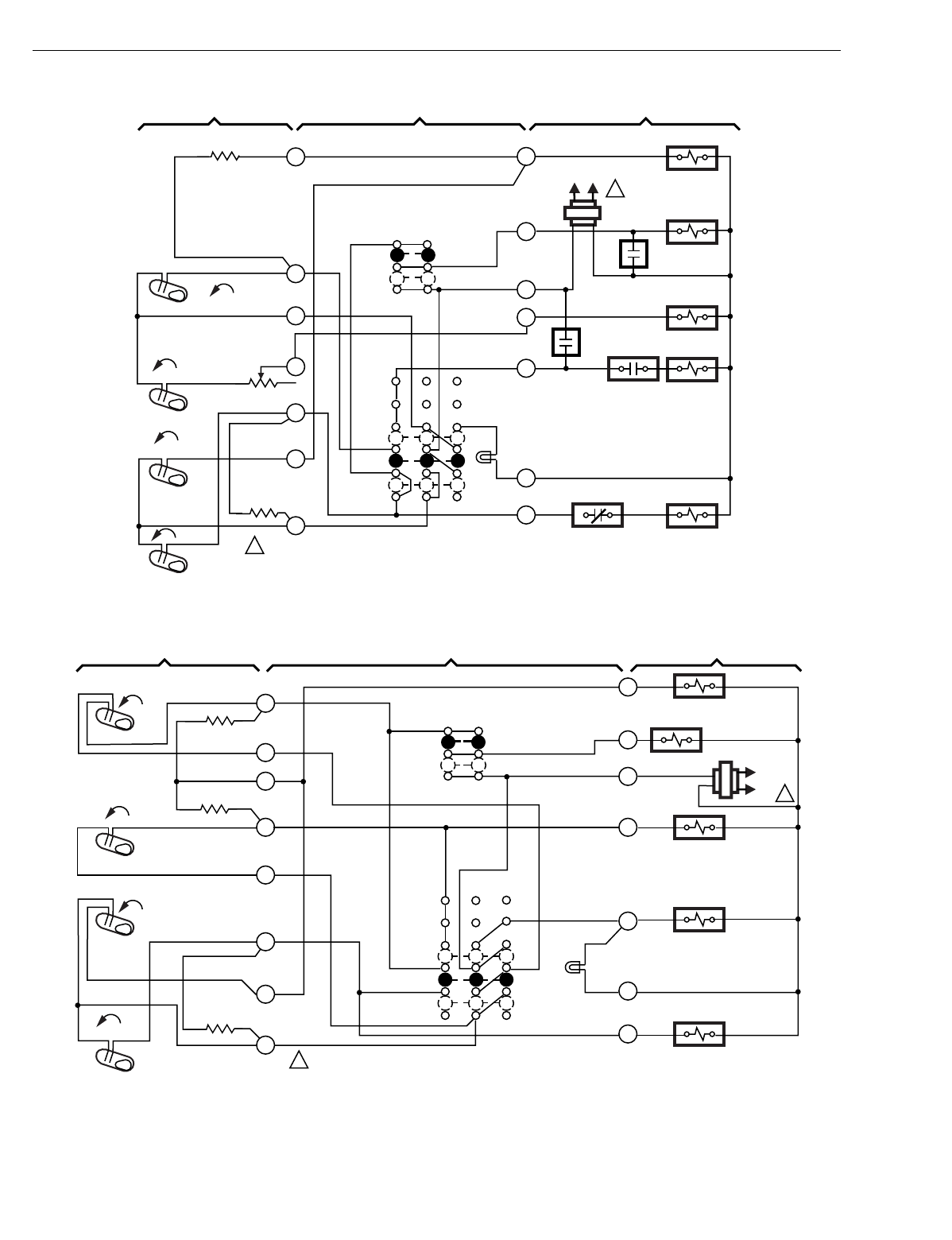
T874 MULTISTAGE THERMOSTATS AND Q674 SUBBASES
60-2485—8168
Fig. 159. Schematic and hookup of T874G with Q674J. Used in heat pump applications.
Fig. 160. Schematic and hookup of T874G with Q674J. Used in heat pump applications.
L1
(HOT) L2
1
H1 FALL
H1 ANTICIPATOR
H2
FALL
CO
RISE
C1
RISE
1
2
4
6
8
9
10
O
G
R
X
Y
W
C1 ANTICIPATOR
E
OFF
AUTO
SYSTEM
SWITCH
FAN SWITCH
OUTDOOR
THERMOSTAT
OFF
AUTO
EM.HT.
EM. HT. LED
(RED)
LIMIT
COMPRESSOR
CONTACTOR
HEAT RELAY
CONTACT
EM. HT.
RELAY
AUX. HT. RELAY
COOL CHANGEOVER VALVE
FAN RELAY
M5722
HEAT RELAY
CONTACT
SYSTEM COMPONENTS
SUBBASETHERMOSTAT
POWER SUPPLY. PROVIDE DISCONNECT MEANS AND OVERLOAD PROTECTION AS REQUIRED.
1
H2 ANTICIPATOR
EM. HT.
AUX. HT. RELAY
POWER SUPPLY. PROVIDE DISCONNECT MEANS AND OVERLOAD PROTECTION AS REQUIRED.
1
RISE
CO
RISE
C1
6
8
9
10
X
B
Y
COMPRESSOR
CONTACTOR
FALL
H2
5W
4
SYSTEM COMPONENTSSUBBASETHERMOSTAT
H1 ANTICIPATOR
2
L1
(HOT)
L2 1
FALL
H1
3
O
G
R
FAN RELAY
COOL CHANGEOVER VALVE
H2 ANTICIPATOR
C1 ANTICIPATOR
FAN
SWITCH
AUTO
ON
SYSTEM
SWITCH
AUTO
OFF
EM. HT.
LED (RED)
M5723
EM. HT. RELAY
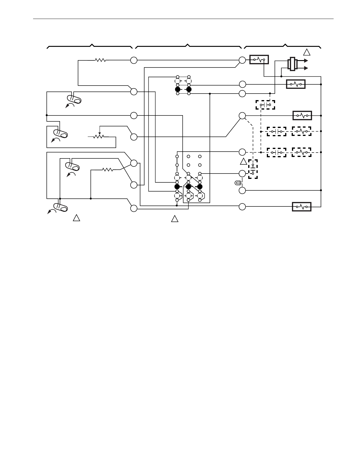
T874 MULTISTAGE THERMOSTATS AND Q674 SUBBASES
169 60-2485—8
Fig. 161. Schematic and hookup of T874G with Q674J. Used in heat pump applications.
H2 ANTICIPATOR
1
SUPL. HT.
LED (RED)
M5724
POWER SUPPLY. PROVIDE DISCONNECT MEANS
AND OVERLOAD PROTECTION AS REQUIRED.
1
SYSTEM COMPONENTSSUBBASETHERMOSTAT
L1
(HOT)
L2
1
H1
FALL
H2
FALL
2
4
6
O
G
R
W2
E
L
C
Y
CO
RISE
C1
RISE
8
9
10
H1 ANTICIPATOR
C1 ANTICIPATOR
SYSTEM
SWITCH
SUPL. HT.
ON
OFF
FAN
SWITCH
AUTO
ON FAN RELAY
COOL CHANGEOVER VALVE
OUTDOOR
THERMOSTAT
EM. HT. RELAY 1
EM. HT. RELAY
CONTACT 1
EM. HT. RELAY 2
EM. HT. RELAY
CONTACT 2 EM.HT.
RELAY 3
2
COMPRESSOR
CONTACTOR 1
N.O. SWITCH — INSTALLER ADDED, TO LIGHT EM. HT. LED
WHEN COMPRESSOR OPERATION IS NOT NORMAL.
2
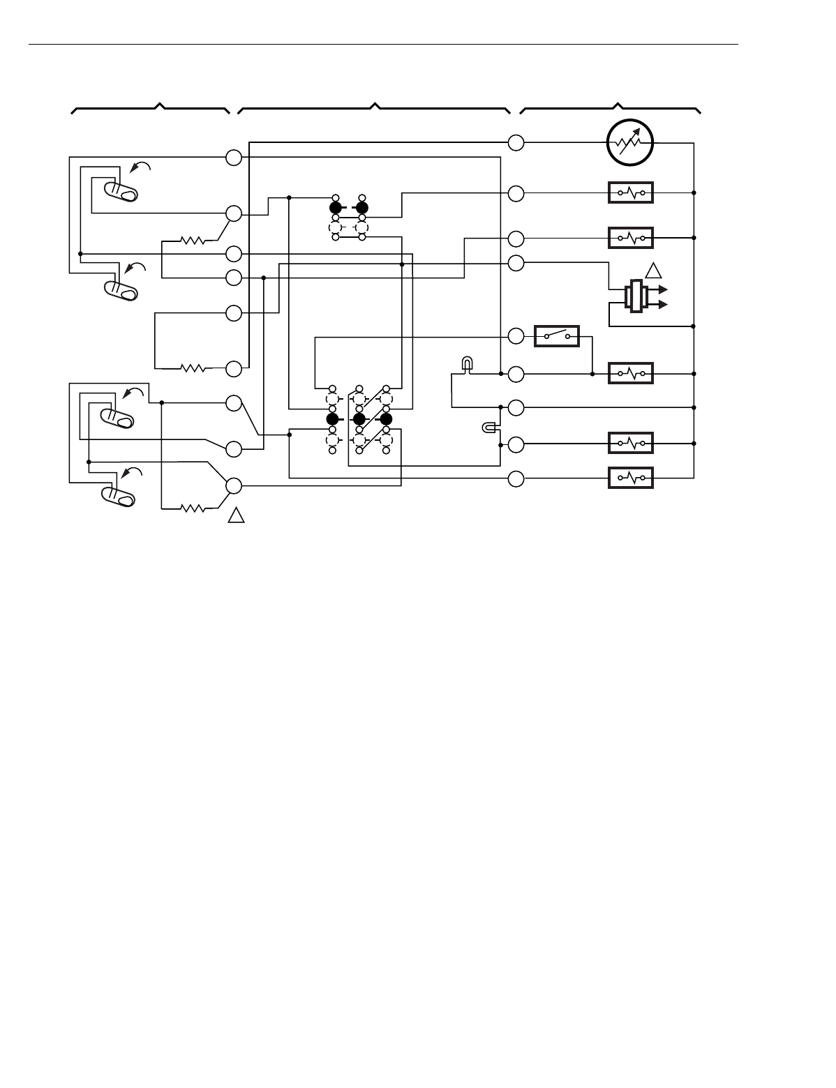
T874 MULTISTAGE THERMOSTATS AND Q674 SUBBASES
60-2485—8170
Fig. 162. Schematic and hookup of T874G with Q674J. Used in heat pump applications.
H1
FALL
EM. HT.
LED (RED)
L1
(HOT)
L2
1
AUX. HT. LED
(GREEN)
F
M5725
POWER SUPPLY. PROVIDE DISCONNECT MEANS AND OVERLOAD PROTECTION AS REQUIRED.
1
SYSTEM COMPONENTSSUBBASETHEROMSTAT
B
W
H2
FALL
CO
RISE
C1
RISE
O
G
T
R
1
2
3
4
5
6
8
9
10 Y
X2
C1
ANTICIPATOR
RESET HEATER
H1 ANTICIPATOR
SYSTEM SWITCH
EM. HT.
AUTO
OFF
FAN SWITCH
AUTO
ON
C815A OUTDOOR
THERMISTOR
FAN RELAY
COOL
CHANGEOVER VALVE
OUTDOOR
THERMOSTAT
AUX. HT. RELAY
EM. HT. RELAY
COMPRESSOR
CONTACTOR
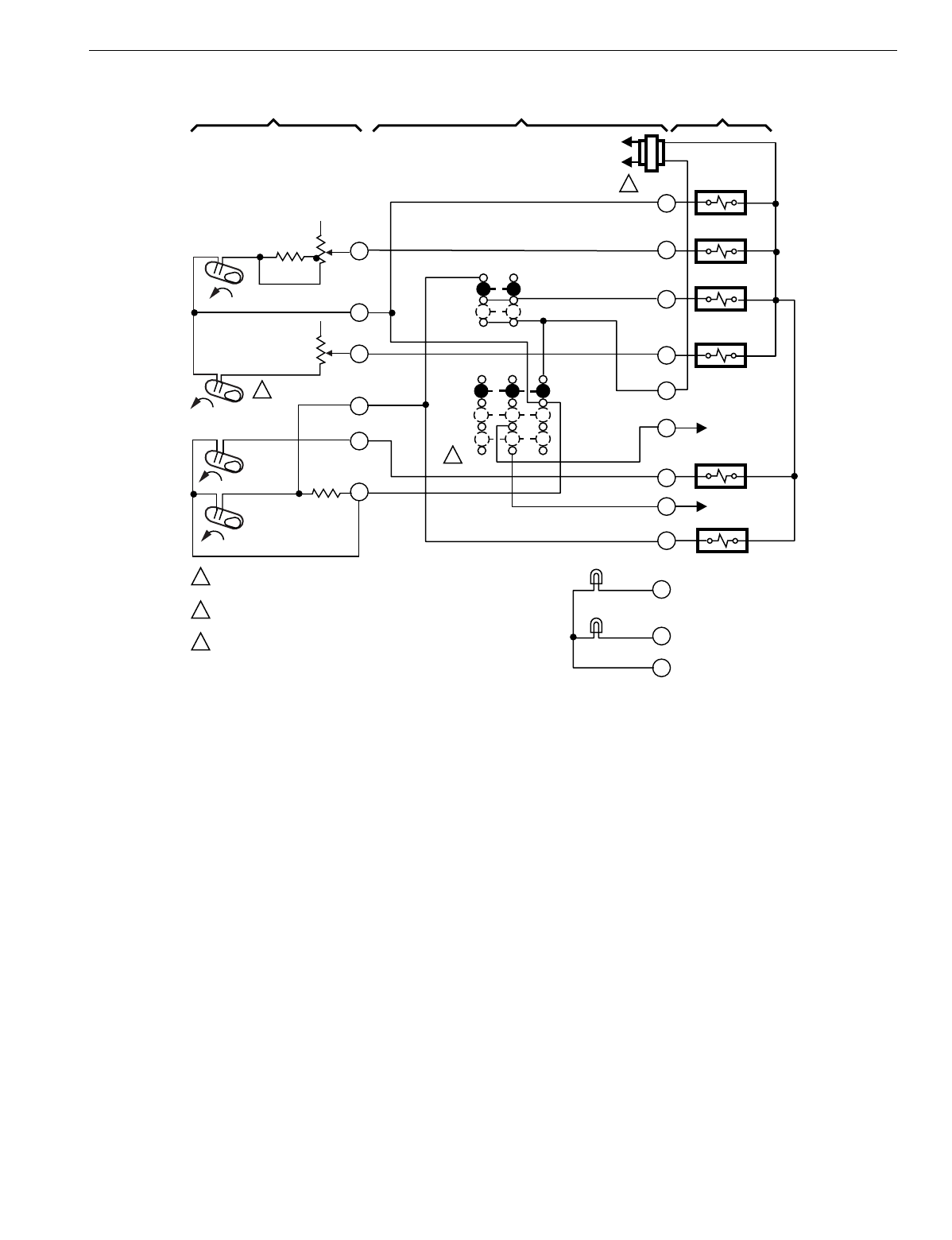
T874 MULTISTAGE THERMOSTATS AND Q674 SUBBASES
171 60-2485—8
Fig. 163. Schematic and hookup of T874G with Q674C. Used in standard applications.
H1
FALL
H2
FALL
CO
FALL
C1
RISE
L1
(HOT)
L2
1
1
1
1
2
3
POWER SUPPLY. PROVIDE DISCONNECT MEANS AND OVERLOAD
PROTECTION AS REQUIRED.
H2 HAS 10¡F FIXED SETBACK FROM H1 ON T874G1485, 0-12¡F
ADJUSTABLE ON T874G1535.
RESET IN MOMENTARY POSITION, SPRING RETURN TO OFF UPON
SWITCH RELEASE.
THERMOSTAT SUBBASE SYSTEM COMPONENTS
1
4
6
8
9
10
C1
ANTICIPATOR
H2
ANTICIPATOR
H1
ANTICIPATOR
FAN
SWITCH
AUTO
ON
SYSTEM
SWITCH
AUTO
OFF
RESET
RESET CIRCUIT
RESET CIRCUIT
COMPRESSOR
RELAY
SERVICE LED (RED)
ON LED (YELLOW)
COOL
CHANAGEOVER VALVE
HEAT RELAY 2
FAN RELAY
HEAT RELAY 1
HEAT DAMPER
C
A
X
Y
S2
O
S1
R
W2
G
W1
B
M1820C
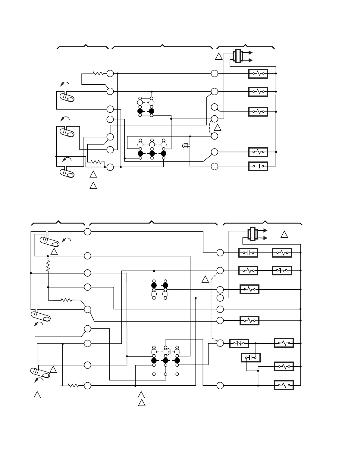
T874 MULTISTAGE THERMOSTATS AND Q674 SUBBASES
60-2485—8172
Fig. 164. Schematic and hookup of T874H with Q674C. Used in standard applications.
Fig. 165. Schematic and hookup of T874L with Q674C. Used in heat pump applications.
H1
FALL
L1
(HOT)
L2
1
2
OFF
FAN SWITCH
SYSTEM SWITCH
C1
ANTICIPATOR
AUTO
ON
M5726
POWER SUPPLY. PROVIDE DISCONNECT MEANS
AND OVERLOAD PROTECTION AS REQUIRED.
1
SYSTEM COMPONENTSSUBBASETHERMOSTAT
3
4
6
8
9
10
O
Y
G
R
L
B
X
2
AUTO
CO
RISE
C1
RISE
R-L JUMPER SUPPLIED BY HONEYWELL.
2
H1
ANTICIPATOR
MALFUNCTION
LED (RED) HEAT CHANGEOVER
VALVE
MALFUNCTION
SWITCH
FAN RELAY
COMPRESSOR
CONTACTOR
COOL CHANGEOVER
VALVE
L1
(HOT)
L2 1
RISE
C1
H1 ANTICIPATOR
1
FAN
SWITCH
ON
AUTO
M5727
POWER SUPPLY. PROVIDE DISCONNECT MEANS
AND OVERLOAD PROTECTION AS REQUIRED.
1
SYSTEM COMPONENTS
SUBBASETHERMOSTAT
SYSTEM
SWITCH
AUTO
OFF
2
3
4
5
7
8
9
10
H2 ANTICIPATOR
J
S
G
C
R
O
H2
H1
FIELD REMOVABLE JUMPER.
2
H1 AND C1 ARE DPST SWITCHES.
3
H2
FALL
H1 FALL
3
3
2
C1
ANTICIPATOR
R1 N.O.2 S1 RELAY
SOLENOID RELAY S1 N.C.
FAN RELAY
AUX. HT. RELAY
R1 N.C.1
COMPRESSOR
CONTACTOR
R2 N.O. 1
R1 RELAY
REV. VALVE
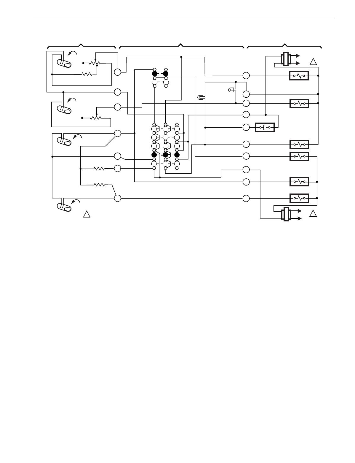
T874 MULTISTAGE THERMOSTATS AND Q674 SUBBASES
173 60-2485—8
Fig. 166. Schematic and hookup of T874D with Q674F. Used in standard applications.
H1
FALL
L1
(HOT)
L2 1
H1 ANTICIPATOR
1
OFF
EM. HT.
SYSTEM
SWITCH
FAN
SWITCH
HEAT
AUTO
COOL
ON
AUTO
M5728
POWER SUPPLY. PROVIDE DISCONNECT MEANS AND OVERLOAD PROTECTION AS REQUIRED.
1
SYSTEM COMPONENTSSUBBASETHERMOSTAT
H2
FALL
C1
RISE
C2
RISE
4
6
8
9
10
11
X
W1
W2
Y2
L
RH
E
G
Y1
RC
L1
(HOT)
L2 1
HEAT RELAY 1
HEAT RELAY 2
EM. HT. RELAY
FAN RELAY
COMRESSOR CONTACTOR 1
AUX. HT. LED
(GREEN)
EM. HT. LED
(RED)
COMRESSOR CONTACTOR 2
SYSTEM
MONITOR
C1 ANTICIPATOR
C2 ANTICIPATOR
H2 ANTICIPATOR
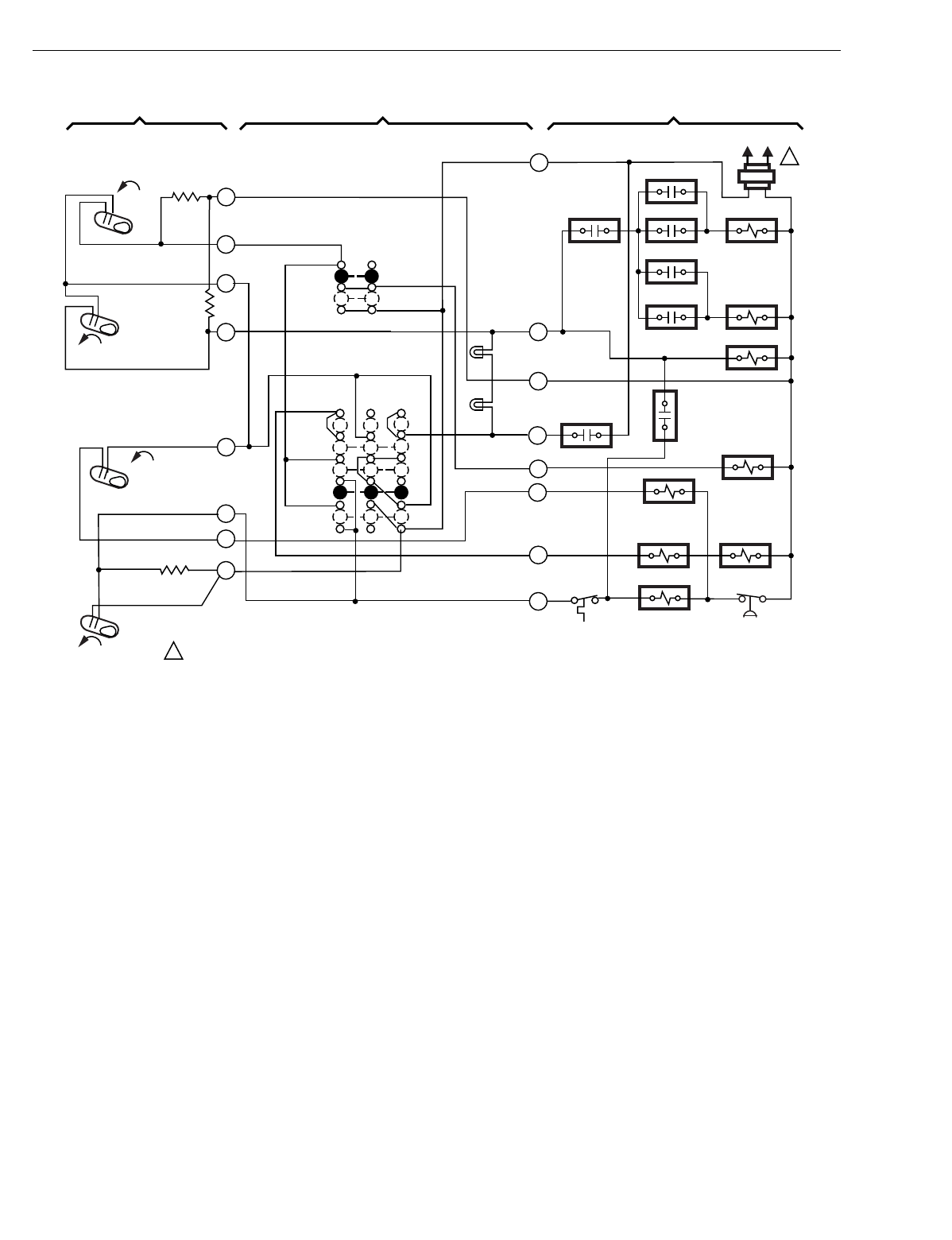
T874 MULTISTAGE THERMOSTATS AND Q674 SUBBASES
60-2485—8174
Fig. 167. Schematic and hookup of T874G with Q674F. Used in heat pump applications.
M1592A
(HOT) L1 L2
1
LACO CHP
Y
B
E
G
L
X
W2
RODT 1
RTD 1 EHR 1 RTD 2
ODT 2
EHR 2 RTD 3
RD
COMPRESSOR
FAILURE
FAN RELAY
COMPRESSOR
CONTACTOR
HEAT
CHANGEOVER
VALVE EM. HT.
RELAY
RTD 1
AUX. HT.
LED (GREEN)
EM. HT.
LED (RED)
FAN SWITCH
ON
AUTO
SYSTEM
SWITCH
EM. HT.
HEAT
AUTO
OFF
COOL
H2
FALL
H1
FALL 2
3
4
5
H1 ANTICIPATOR
H2
ANTICIPATOR
C1
RISE
FALL
7
8
9
10
C1
ANTICIPATOR
1POWER SUPPLY. PROVIDE DISCONNECT MEANS AND OVERLOAD PROTECTION AS REQUIRED.
THERMOSTAT SUBBASE SYSTEM COMPONENTS
EHT1
CHANGEOVER
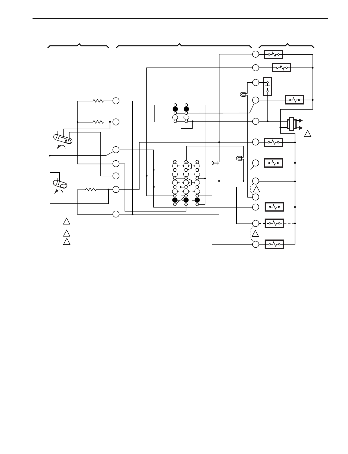
T874 MULTISTAGE THERMOSTATS AND Q674 SUBBASES
175 60-2485—8
Fig. 168. Schematic and hookup of T874R with Q674L. Used in heat pump applications.
H1
FALL
C
L1
(HOT)
L2
1
EM. HT.
LED (RED)
AUX. HT.
LED (GRN)
W3
O
L
G
R
W2
E
X
X2
B
W1
Y
AUX. HT. RELAY
EM. HT. RELAY
HEAT
CHANGEOVER
VALVE
W1 RELAY
COMPRESSOR
RELAY
W3 RELAY
COOL CHANGEOVER
VALVE
COMPRESSOR
MONITOR
FAN RELAY
H2
FALL
H1
ANTICIPATOR
C ANTICIPATOR
H2
ANTICIPATOR
POWER SUPPLY. PROVIDE DISCONNECT MEANS AND OVERLOAD
PROTECTION AS REQUIRED.
REMOVE JUMPER WHEN W1 RELAY IS USED.
FACTORY-INSTALLED JUMPER.
1
M5067
FAN
SWITCH
AUTO
ON
SYSTEM
SWITCH
EM. HT.
HEAT
OFF
COOL
3
2
2
3
THERMOSTAT SUBBASE SYSTEM COMPONENTS
1
2
3
4
5
6
11
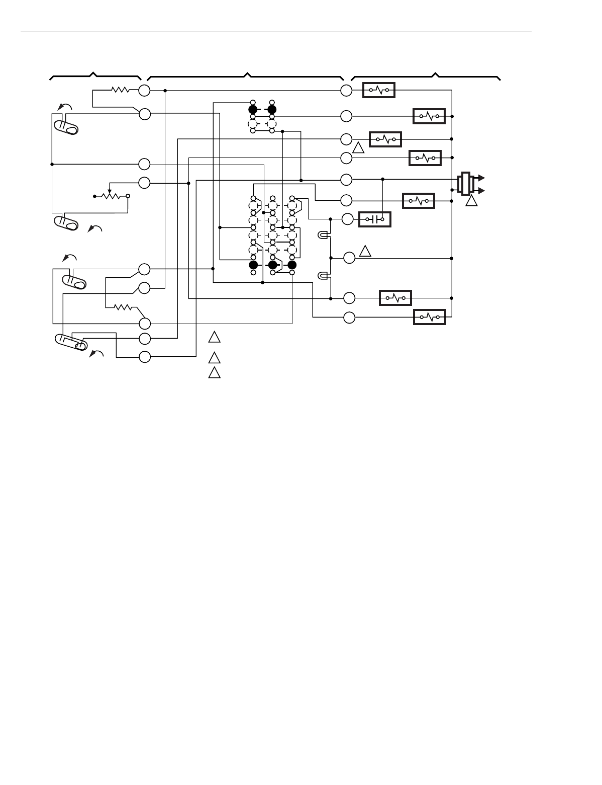
T874 MULTISTAGE THERMOSTATS AND Q674 SUBBASES
60-2485—8176
Fig. 169. Schematic and hookup of T874G with Q674F. Used in heat pump applications.
H1
FALL
RISE
CO
L1
(HOT)
L2
1
3
C1
RISE 1
2
2
3
POWER SUPPLY. PROVIDE DISCONNECT MEANS AND
OVERLOAD PROTECTION AS REQUIRED.
TERMINAL LABELED C/X ON SOME MODELS.
W3 TERMINAL ON SOME MODELS ONLY.
C1 ANTICIPATOR
H1 ANTICIPATOR FAN SWITCH
AUTO
ON
SYSTEM
SWITCH
AUTO
HEAT
OFF
COOL
1
2
4
6
8
9
10
O
W2
X
E
L
B
W3
R
G
Y
AUX. HT. RELAY
FAN RELAY
EM. HT. RELAY
B RELAY
M5986A
THERMOSTAT SUBBASE SYSTEM COMPONENTS
11
12
COMPRESSOR
CONTACTOR
EM. HT.
EM. HT.
LED (RED)
AUX. HT.
LED (GREEN)
COOL CHANGEOVER
VALVE
H2
FALL
H2
ANTICIPATOR
AUX HT. RELAY
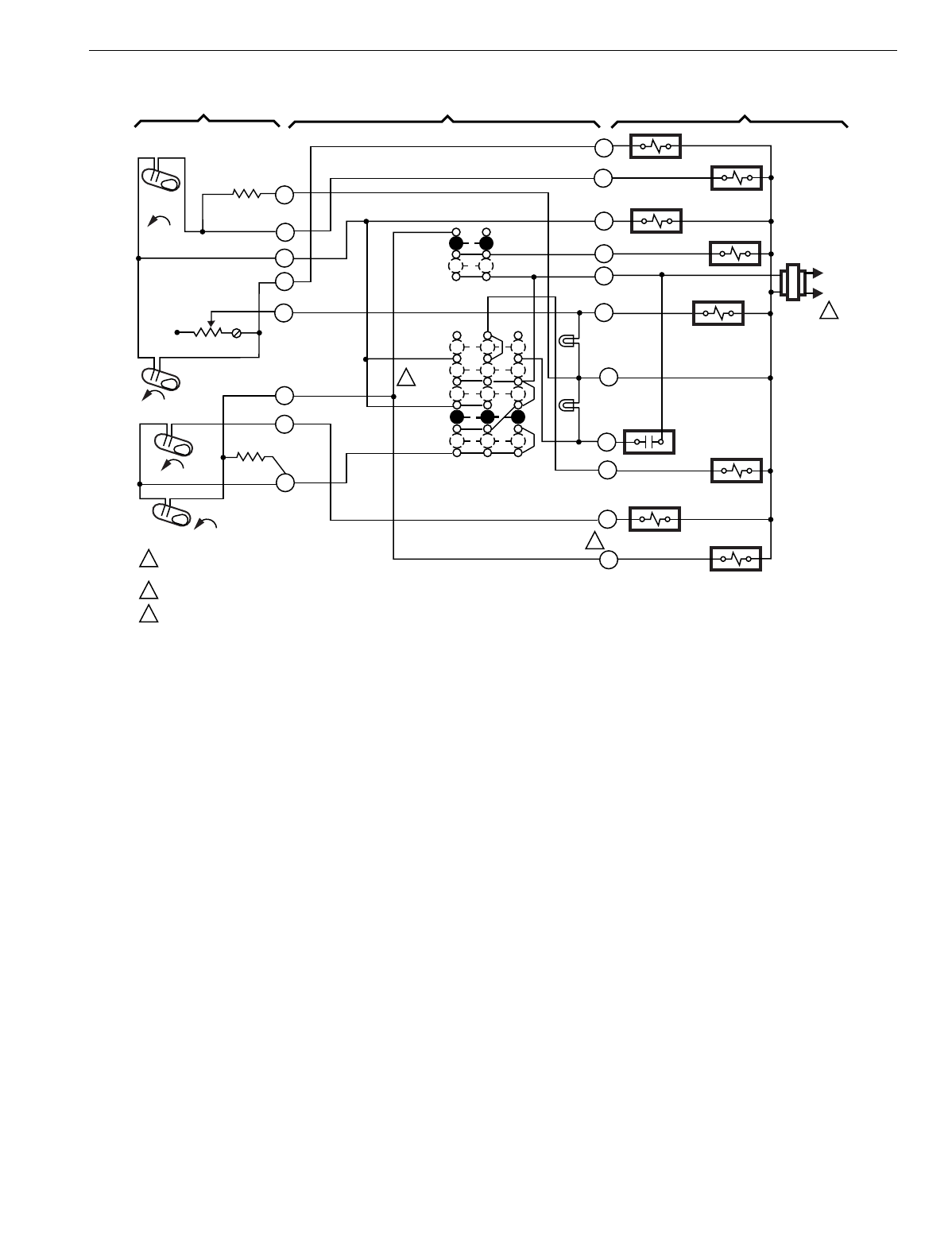
T874 MULTISTAGE THERMOSTATS AND Q674 SUBBASES
177 60-2485—8
Fig. 170. Schematic and hookup of T874G with Q674F. Used in heat pump applications.
H1
FALL
RISE
CO
L1
(HOT)
L2
1
C1
RISE
1
2
3
3
2
POWER SUPPLY. PROVIDE DISCONNECT
MEANS AND OVERLOAD PROTECTION AS REQUIRED.
ON SOME MODELS, Y TERMINAL MAY BE LABELED Y1.
EMERGENCY HEAT RUNS CONTINUOUSLY WHEN SWITCH IN IN EM. HT. POSITION.
C1 ANTICIPATOR
H1 ANTICIPATOR FAN SWITCH
AUTO
ON
SYSTEM
SWITCH
AUTO
HEAT
OFF
COOL
2
4
8
9
10
W2
X
L
B
R
G
Y
AUX. HT. RELAY
FAN RELAY
EM. HT.
RELAY
B RELAY
M5987A
THERMOSTAT SUBBASE SYSTEM COMPONENTS
COMPRESSOR
CONTACTOR
EM. HT.
EM. HT.
LED (RED)
AUX. HT.
LED (GREEN)
H2
FALL
H2
ANTICIPATOR
3
5
W3
W1
W3 RELAY W1 RELAY
COOL
CHANGEOVER
VALVE
COMPRESSOR
FAULT
E
O
6
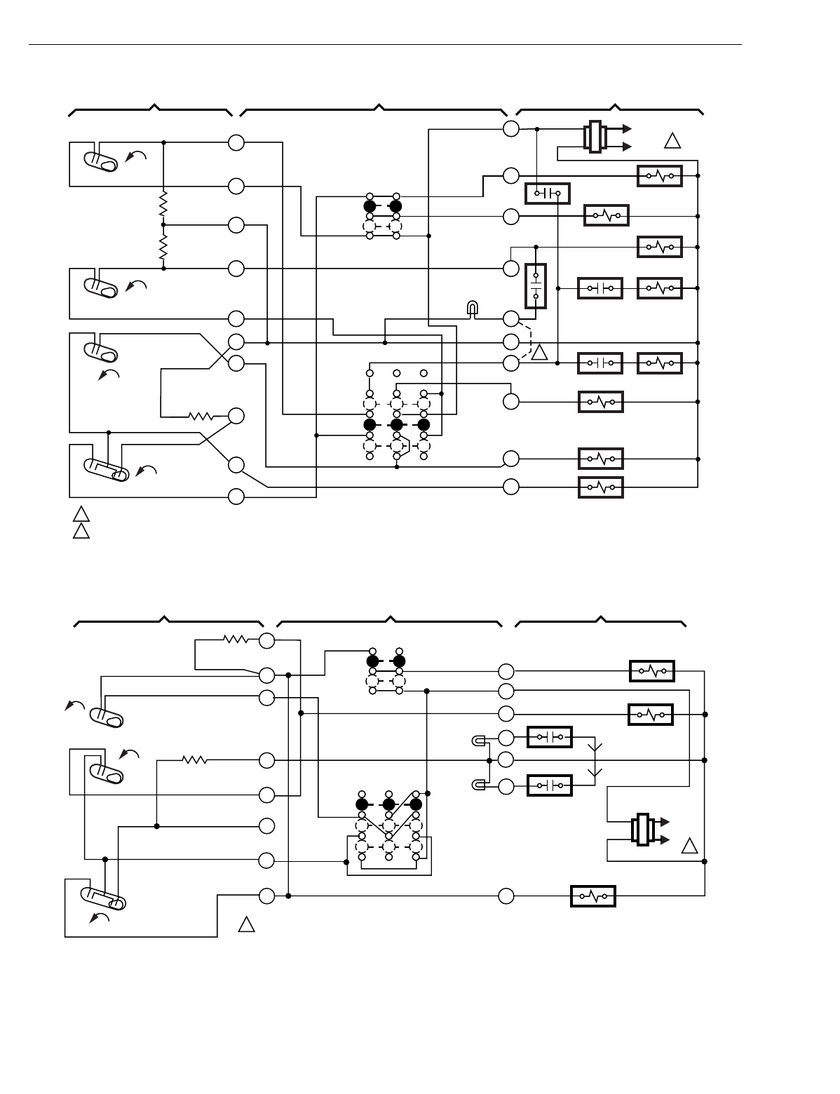
T874 MULTISTAGE THERMOSTATS AND Q674 SUBBASES
60-2485—8178
Fig. 171. Schematic and hookup of T874J with Q674J. Used in heat pump applications.
Fig. 172. Schematic and hookup of T874H with Q674B. Used in heat pump applications.
H1
FALL
C1 RISE
CO
L1
(HOT)
L2 1
H1 ANTICIPATOR
OFF
EM. HT.
SYSTEM
SWITCH
FAN
SWITCH
AUTO
ON
AUTO
EM. HT. LED
(RED)
2
FAN RELAY
M5729
POWER SUPPLY. PROVIDE DISCONNECT MEANS AND OVERLOAD PROTECTION AS REQUIRED.
1
SYSTEM COMPONENTS
SUBBASE
THERMOSTAT
H2 FALL
CO
RISE
3
4
5
6
8
9
10
11
12
EXTERNAL JUMPER SUPPLIED BY HONEYWELL.
2
R
Y
G
F
C
E
X
P
O
W1
2
H2 ANTICIPATOR
C1 ANTICIPATOR
COMPRESSOR
CONTACTOR
O.D.T.
HCR1
HCR1
"X" RELAY
"P" RELAY
COOL CHANGEOVER
VALVE
HCR2
HCR2 HCR3
H1
FALL
CO
RISE
L1
(HOT)
L2 1
1POWER SUPPLY. PROVIDE DISCONNECT MEANS AND
OVERLOAD PROTECTION AS REQUIRED.
THERMOSTAT SUBBASE SYSTEM COMPONENTS
H1 ANTICIPATOR
C1 ANTICIPATOR SYSTEM
SWITCH
FAN
SWITCH
AUTO
ON
OFF
HEAT
COOL
COOL
CHANGEOVER
VALVE
COMPRESSOR
CONTACTOR M1401
FAULT
LED
(RED)
CHECK
FILTER
LED (YELLOW)
FAN RELAY
12
11
10
9
8
4
3
2
G
R
O
2
C
3
Y
RISE
C1
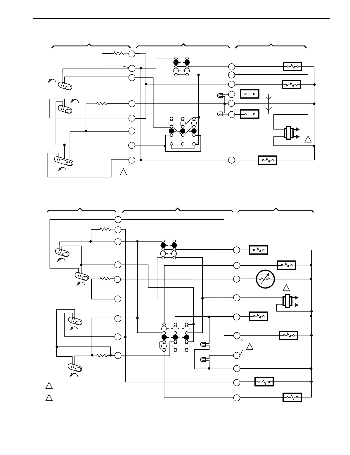
T874 MULTISTAGE THERMOSTATS AND Q674 SUBBASES
179 60-2485—8
Fig. 173. Schematic and hookup of T874H with Q674C. Used in heat pump applications.
Fig. 174. Schematic and hookup of T874G with Q674J. Used in heat pump applications.
H1
FALL
CO
RISE
L1
(HOT)
L2 1
1POWER SUPPLY. PROVIDE DISCONNECT MEANS AND
OVERLOAD PROTECTION AS REQUIRED.
THERMOSTAT SUBBASE SYSTEM COMPONENTS
H1 ANTICIPATOR
C1 ANTICIPATOR SYSTEM
SWITCH
FAN
SWITCH
AUTO
ON
OFF
AUTO
COOL
CHANGEOVER
VALVE
COMPRESSOR
CONTACTOR M1400
FAULT
LED
(RED)
CHECK
FILTER
LED (YELLOW)
FAN RELAY
12
11
10
9
8
4
3
2
G
R
O
2
C
3
Y
RISE
C1
H1
FALL
H2
FALL
C1
RISE
C2
RISE
L1
(HOT)
L2
1
1
2
2
POWER SUPPLY. PROVIDE DISCONNECT MEANS AND
OVERLOAD PROTECTION AS REQUIRED.
REMOVABLE JUMPER.
THERMOSTAT SUBBASE SYSTEM COMPONENTS
HA
CA
ODA
SYSTEM
SWITCH
FAN
SWITCH
AUTO
ON
OFF
EM. HT.
AUTO
EM.. HT. RELAY
AUX. HT. RELAY
M1403
1
2
3
4
5
6
8
9
10
X2
G
T
R
F
W
U
B
O
Y
COMPRESSOR
CONTACTOR
COOL CHANGEOVER
VALVE
"F" RELAY
C815A
OUTDOOR
THERMISTOR
FAN RELAY
EM. HT.
LED (RED)
AUX. HT.
LED (GREEN)
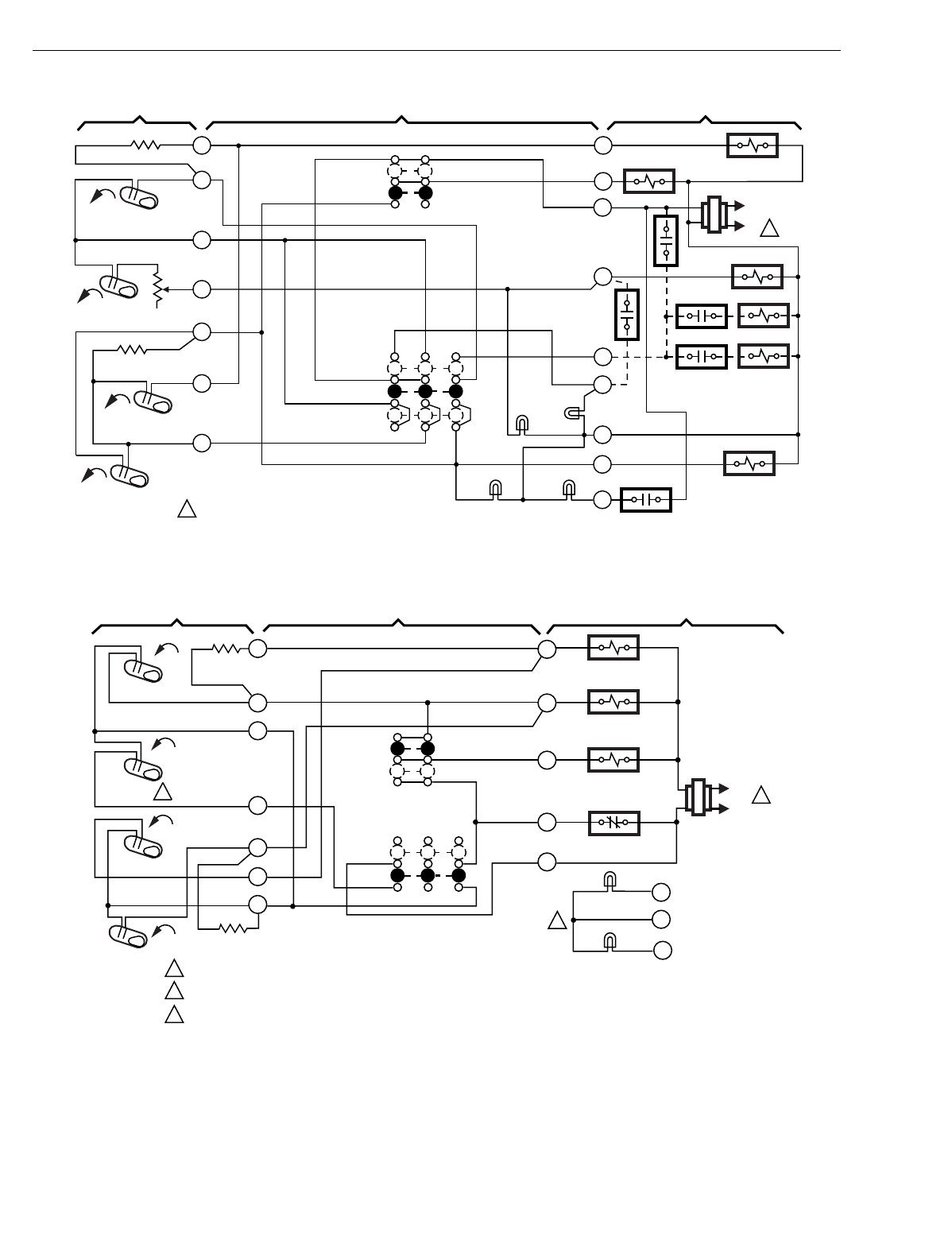
T874 MULTISTAGE THERMOSTATS AND Q674 SUBBASES
60-2485—8180
Fig. 175. Schematic and hookup of T874G with Q674J. Used in heat pump applications.
Fig. 176. Schematic and hookup of T874G with Q674C. Used in standard applications.
FALL L1
(HOT)
L2 1
O
G
R
W2
E
L
C
Y
2
4
6
8
POWER SUPPLY. PROVIDE DISCONNECT MEANS AND OVERLOAD
PROTECTION AS REQUIRED.
1
THERMOSTAT SUBBASE SYSTEM COMPONENTS
FAN
SWITCH
AUTO
ON
SYSTEM
SWITCH
SUPL. HT.
ON
OFF
M2112A
H1 ANTICIPATOR
D
COOL
CHANGEOVER VALVE
FAN RELAY
H.C.R. 1
H.C.R. 1 H.C.R.2
H.C.R. 2 H.C.R.3
COMPRESSOR
CONTACTOR
1
9
10
FALL
CO
RISE
C1 ANTICIPATOR
H2
ANTICIPATOR
C1
RISE
HEAT PUMP
(GRN)
DEFROST
(RED)
MANUAL
(RED)
AUTO
(YEL)
O.D.T.
H1
FALL
L1
(HOT)
L2
1
H1 ANTICIPATOR
2
OFF
AUTO
SYSTEM
SWITCH
FAN SWITCH
ON
AUTO
FAN RELAY
M5730
POWER SUPPLY. PROVIDE DISCONNECT MEANS AND OVERLOAD PROTECTION AS REQUIRED.
SETBACK STAGE OFFSET 12°F (7°C) FROM H1 STAGE.
LEDS ON SOME MODELS.
1
SYSTEM COMPONENTSSUBBASETHERMOSTAT
SETBACK
FALL
CO
RISE
C1 RISE
3
4
6
8
10
9
Y2
G
R
L
2
2
Y1
COMPRESSOR
CONTACTOR
OPEN-NIGHT
CLOSED-DAY
C1 ANTICIPATOR
SETBACK RELAY
COOL
CHANGEOVER VALVE
LED X1
C
X2
LED
3
3
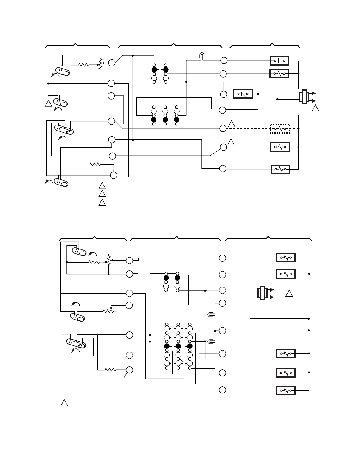
T874 MULTISTAGE THERMOSTATS AND Q674 SUBBASES
181 60-2485—8
Fig. 177. Schematic and hookup of T874G,H with Q674C. Used in standard applications.
Fig. 178. Schematic and hookup of T874N with Q674F. Used in heat pump applications.
H1
FALL
L1
(HOT)
L2
1
FALL
M114C
POWER SUPPLY. PROVIDE DISCONNECT MEANS AND OVERLOAD PROTECTION AS REQUIRED.
USE EITHER 'B' OR 'O' ONLY FOR SYSTEM CHANGEOVER. 0.8A AT 30 VAC MAXIMUM LOAD CURRENT.
SECOND STAGE HEAT MAKES 12oF (7oC) AFTER FIRST STAGE HEAT TO PROVIDE SETBACK
1
2
2
THERMOSTAT SUBBASE SYSTEM COMPONENTS
1
R2
R1
B
O
Y
G
FAN
SWITCH
AUTO
ON
SYSTEM SWITCH
RESET LED
(RED)
OFF
AUTO
C1
H2
H1 ANTICIPATOR
FAN RELAY
COOL
CHANGEOVER VALVE
HEAT CHANGEOVER
VALVE
COMPRESSOR
CONTACTOR
C1 ANTICIPATOR
RISE
2
3
3
RISE
CO
4
6
7
8
9
10
LOCKOUT
(RESET) RELAY
X
H2
FALL
C0
RISE
H1
FALL
M18623
H1 ANTICIPATOR
H2 ANTICIPATOR
C1 ANTICIPATOR
POWER SUPPLY. PROVIDE DISCONNECT MEANS AND OVERLOAD PROTECTION AS REQUIRED.
1
1
3
4
6
8
9
10
K
L
W2
R
G
W1
SYSTEM
SWITCH
HEAT
EM.HT.
OFF
COOL
AUTO
ON
AUTO
FAN
SWITCH
SERVICE
LED (RED)
EM, HT. LED
(YELLOW)
AUX.HT. RELAY
FAN RELAY
CHANGEOVER RELAY
COMPRESSOR RELAY
EM.HT. RELAY
C
X
THERMOSTAT SUBBASE SYSTEM COMPONENTS
L1
(HOT)
L2 1
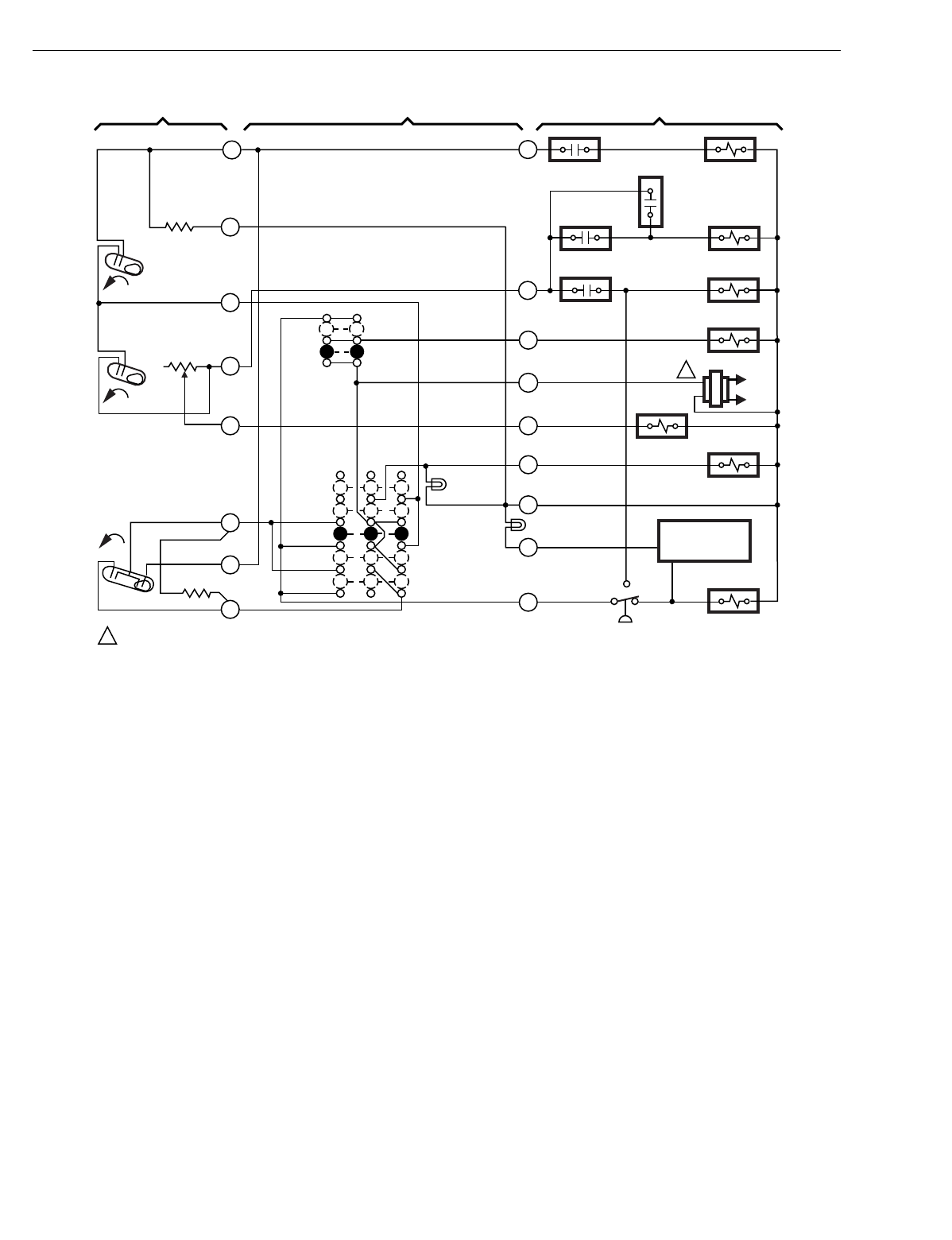
T874 MULTISTAGE THERMOSTATS AND Q674 SUBBASES
60-2485—8182
Fig. 179. Schematic and hookup of T874N with Q674F. Used in heat pump applications.
L1
(HOT)
L2
1
W1
W2
EM. HT.
LED (RED)
CHECK
LED
(GREEN)
FAN RELAY
G
EM. HT.
RELAY
COMPRESSOR
CONTACTOR
Y
E
SYSTEM
SWITCH
EM. HT.
HEAT
OFF
COOL
H1
ANTICIPATOR
H1
H2
H2
ANTICIPATOR
1POWER SUPPLY. PROVIDE DISCONNECT MEANS AND OVERLOAD PROTECTION AS REQUIRED. M3686
FALL
R
RISE L
C1
HEAT
RELAY 3
EM.HT. RELAY
CONTACT
OUTDOOR
THERMOSTAT
AUTO
ON
FAN SWITCH
X
W3
OPTIONAL
COMPRESSOR
FAILURE DEVICE
DEFROST
RELAY REVERSING
VALVE
EM.HT. RELAY
CONTACT
HIGH
PRESSURE
SWITCH
HEAT
RELAY 1
HEAT
RELAY 2
AUTO
FALL
CO
C1
ANTICIPATOR
1
2
4
5
6
8
9
10
THERMOSTAT SUBBASE SYSTEM COMPONENTS
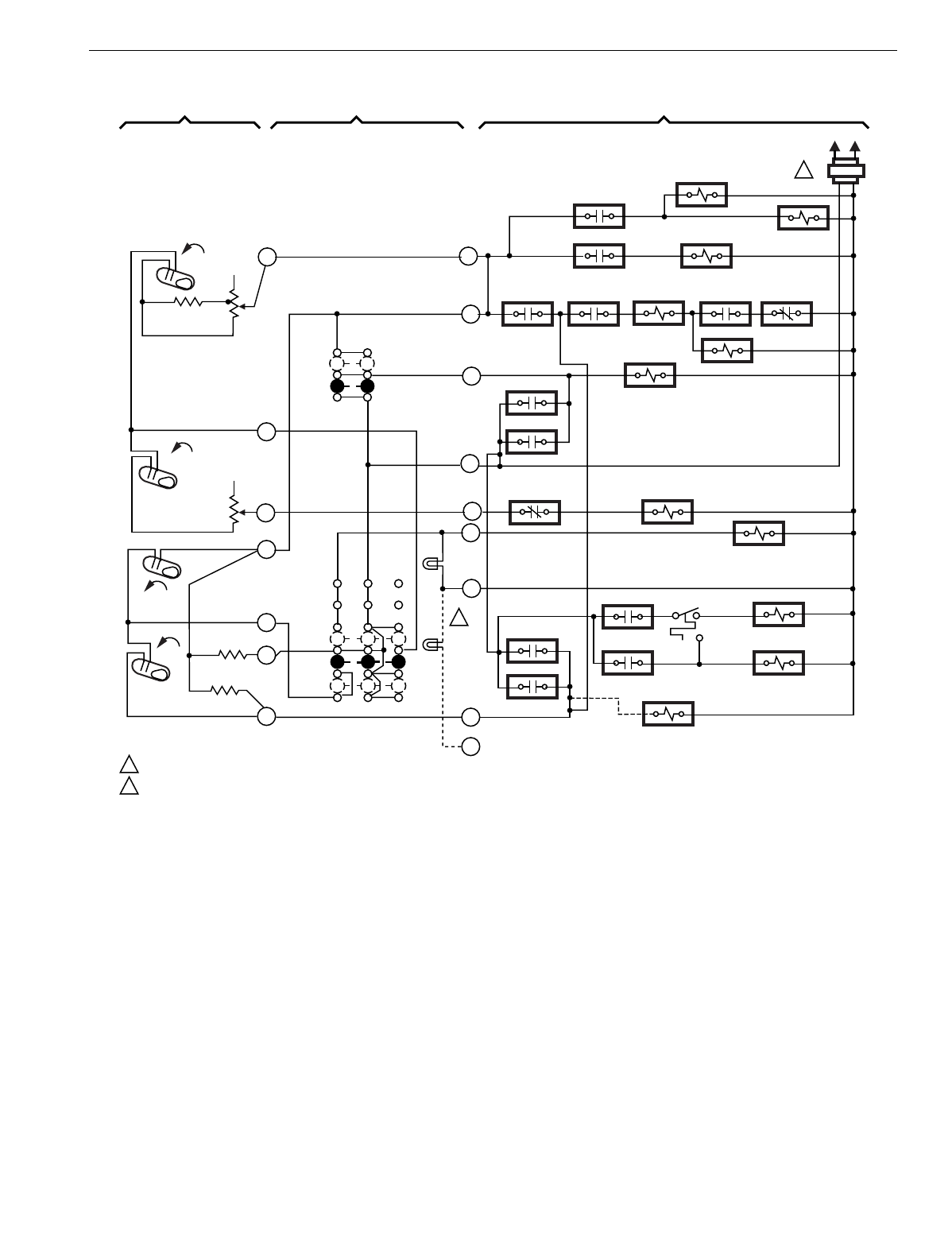
T874 MULTISTAGE THERMOSTATS AND Q674 SUBBASES
183 60-2485—8
Fig. 180. Schematic and hookup of T874A,D with Q674J. Used in heat pump applications.
H1
FALL
L1
(HOT)
L2
1
H1
FALL
C1
RISE
C2
RISE
M5957
POWER SUPPLY. PROVIDE DISCONNECT MEANS AND OVERLOAD PROTECTION AS REQUIRED.
FILTER LED ON SOME MODELS.
C2 ANTICIPATOR
C1 ANTICIPATOR
SYSTEM
SWITCH
EM. HT.
AUTO
OFF
FILTER
LED
(YELLOW)
R-3
R-6
RANDOM START
R-8 (OPT.)
R-5
R-5 T2
(HEAT PUMP
OPERATION) R-10
(BIOLERLESS
OPERATION ) R-11
EM. HT. RELAY
ELEC. HT. RELAY
STG. 2
R-10
R-2
R-1
FAN RELAY
R-6
OVERLOADR-6
COMPRESSOR
CONTACTOR
R-8
R-10
R-11
R-11 CHANGEOVER VALVE ELEC. HT.
RELAY STG. 1
FAN DELAY
RELAY
W1
Y1
G
R
W2
EM. HT.
LED
(RED)
E
X2
Y2
X1
1
4
6
8
9
10
11
H1
ANTICIPATOR
1
2
2
H2
ANTICIPATOR
SYSTEM COMPONENTS
SUBBASE
THERMOSTAT
FAN
SWITCH
AUTO
ON
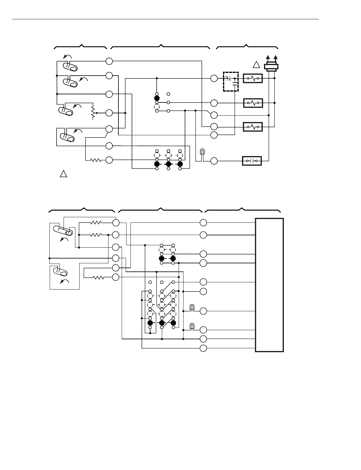
T874 MULTISTAGE THERMOSTATS AND Q674 SUBBASES
60-2485—8184
Fig. 181. Schematic and hookup of T874K with Q674C. Used in heat pump applications.
Fig. 182. Schematic and hookup of T874R with Q674L. Used in heat pump applications.
FALL
CO
L1
(HOT)
L2
1
1
H2 FALL
H1
FALL
C1
RISE
2
3
6
8
9
10
Y
G
R
W
W2
A
COMPRESSOR
FAULT
REVERSING
VALVE
FAN RELAY
COMPRESSOR
RELAY
TIME
CLOCK
FAN
SWITCH
AUTO
ON
SYSTEM
SWITCH
OFF
AUTO
COMPRESSOR
FAULT LED (RED)
C1
ANTICIPATOR
H1
ANTICIPATOR
THERMOSTAT SUBBASE SYSTEM COMPONENT
M18587
4
POWER SUPPLY. PROVIDE DISCONNECT MEANS AND OVERLOAD PROTECTION AS REQUIRED.
FAN
SYSTEM
SWITCH
COOL
HEAT
H1/C
ANTICIPATOR
H1
FALL
M3951
AUTO
ON
FAN
SWITCH
R
G
L
Y
X
H2
E
W2
B
EM. HT.
LED (YELLOW)
1
2
3
5
4
6
SERVICE
LED (RED)
COMPRESSOR
FALL
AUX. HT.
O
T
OUTDOOR
RESET
EM. HT.
OFF
EM. HT.
W89
HEAT
PUMP
CONTROL
PANEL
COOL/HEAT
H2
ANTICIPATOR
RESET
SERVICE
LIGHT
EM. HT. LIGHT
THERMOSTAT SUBBASE SYSTEM COMPONENTS
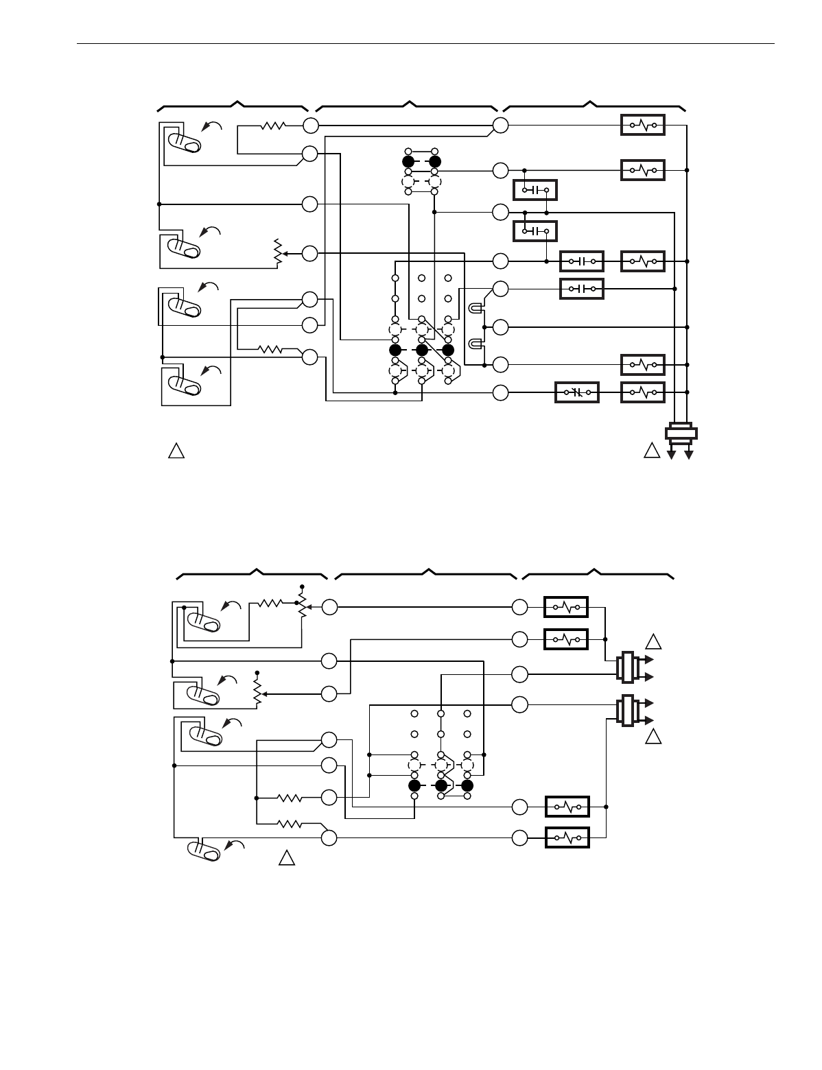
T874 MULTISTAGE THERMOSTATS AND Q674 SUBBASES
185 60-2485—8
Fig. 183. Schematic and hookup of T874G with Q674J. Used in heat pump applications.
Fig. 184. Schematic and hookup of T874A,F with Q674G. Used in standard applications.
L1
(HOT)
L2
1
FAN RELAY
SYSTEM
SWITCH
OFF
EM. HT.
H1
ANTICIPATOR
H1
FALL
1POWER SUPPLY. PROVIDE DISCONNECT MEANS
AND OVERLOAD PROTECTION AS REQUIRED.
M3950
AUTO
ON
FAN
SWITCH
R
G
CO
W
Y
X
H2
RISE
E
O
C1
ANTICIPATOR
C1
RISE
L1
EM. HT.
LED (RED)
ON
1
2
4
6
8
9
10
AUX. HT.
LED (GREEN)
COMPRESSOR
CONTACTOR
COMPRESSOR
FAILURE
FALL COOL CHANGEOVER
VALVE
2BH
O. D. S.
1BH SH
1BH
H2
ANTICIPATOR
THERMOSTAT SUBBASE SYSTEM COMPONENTS
L1
(HOT)
L2
1
SYSTEM
SWITCH
OFF
H1
ANTICIPATOR
H1
FALL
1POWER SUPPLY. PROVIDE DISCONNECT MEANS
AND OVERLOAD PROTECTION AS REQUIRED. M3953
RH
C1
Y1
H2
RISE
W1
C1
ANTICIPATOR
C2
RISE
AUTO
1
4
6
8
9
10
COMPRESSOR
CONTACTOR 2
FALL
HEAT RELAY 1
RC
Y2
11
C2
ANTICIPATOR
W2
HEAT RELAY 2
COMPRESSOR
CONTACTOR 1
L1
(HOT)
L2
1
H2
ANTICIPATOR
THERMOSTAT SUBBASE SYSTEM COMPONENTS
NO
FAN
SWITCH
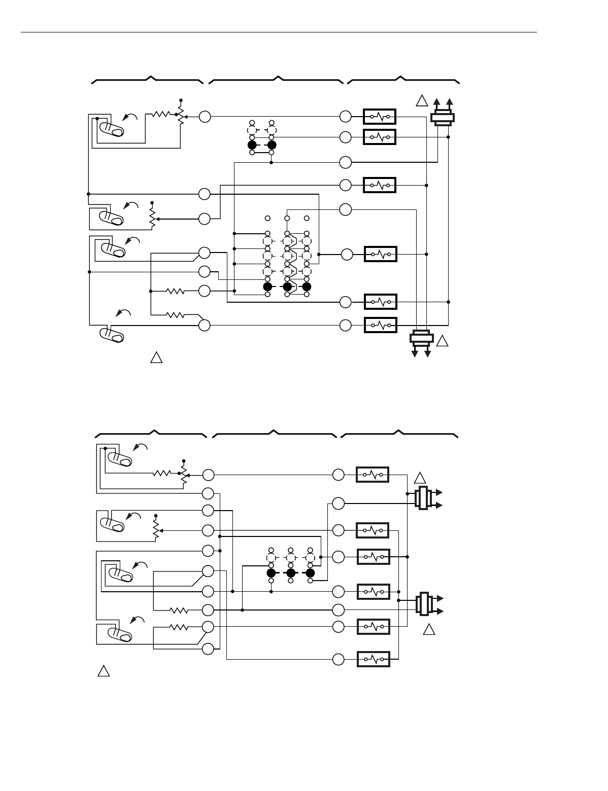
T874 MULTISTAGE THERMOSTATS AND Q674 SUBBASES
60-2485—8186
Fig. 185. Schematic and hookup of T874D with Q674E. Used in standard applications.
Fig. 186. Schematic and hookup of T874D with Q674G. Used in standard applications.
L1
(HOT)
L2
1
SYSTEM
SWITCH
AUTO
H1
ANTICIPATOR
H1
FALL
1POWER SUPPLY. PROVIDE DISCONNECT MEANS
AND OVERLOAD PROTECTION AS REQUIRED.
M3954
RH
C1
Y1
H2
RISE
W1
C1
ANTICIPATOR
C2
RISE
COOL
1
4
6
8
9
10
COMPRESSOR
CONTACTOR 2
FALL
HEAT RELAY
RC
Y2
11
C2
ANTICIPATOR
W2
HEAT RELAY 2
COMPRESSOR
CONTACTOR 1
L1
(HOT)
L2
1
AUTO
ON
FAN
SWITCH
FAN RELAY
IGNITION
RELAY
OFF
HEAT B
G
H2
ANTICIPATOR
THERMOSTAT SUBBASE SYSTEM COMPONENTS
L1
(HOT)
L2
1
SYSTEM
SWITCH
OFF
H1
ANTICIPATOR
H1
FALL
1POWER SUPPLY. PROVIDE DISCONNECT MEANS
AND OVERLOAD PROTECTION AS REQUIRED. M3955
RH
C1
Y1
H2
RISE
W1
C1
ANTICIPATOR
C2
RISE
AUTO
1
4
6
8
9
10
COMPRESSOR
CONTACTOR 2
FALL
HEAT RELAY 1
RC
Y2
11
C2
ANTICIPATOR
W2
HEAT RELAY 2
COMPRESSOR
CONTACTOR 1
L1
(HOT)
L2
1
12
B
5
7
FAN RELAY
O
FAN RELAY
H2
ANTICIPATOR
THERMOSTAT SUBBASE SYSTEM COMPONENTS
NO
FAN
SWITCH
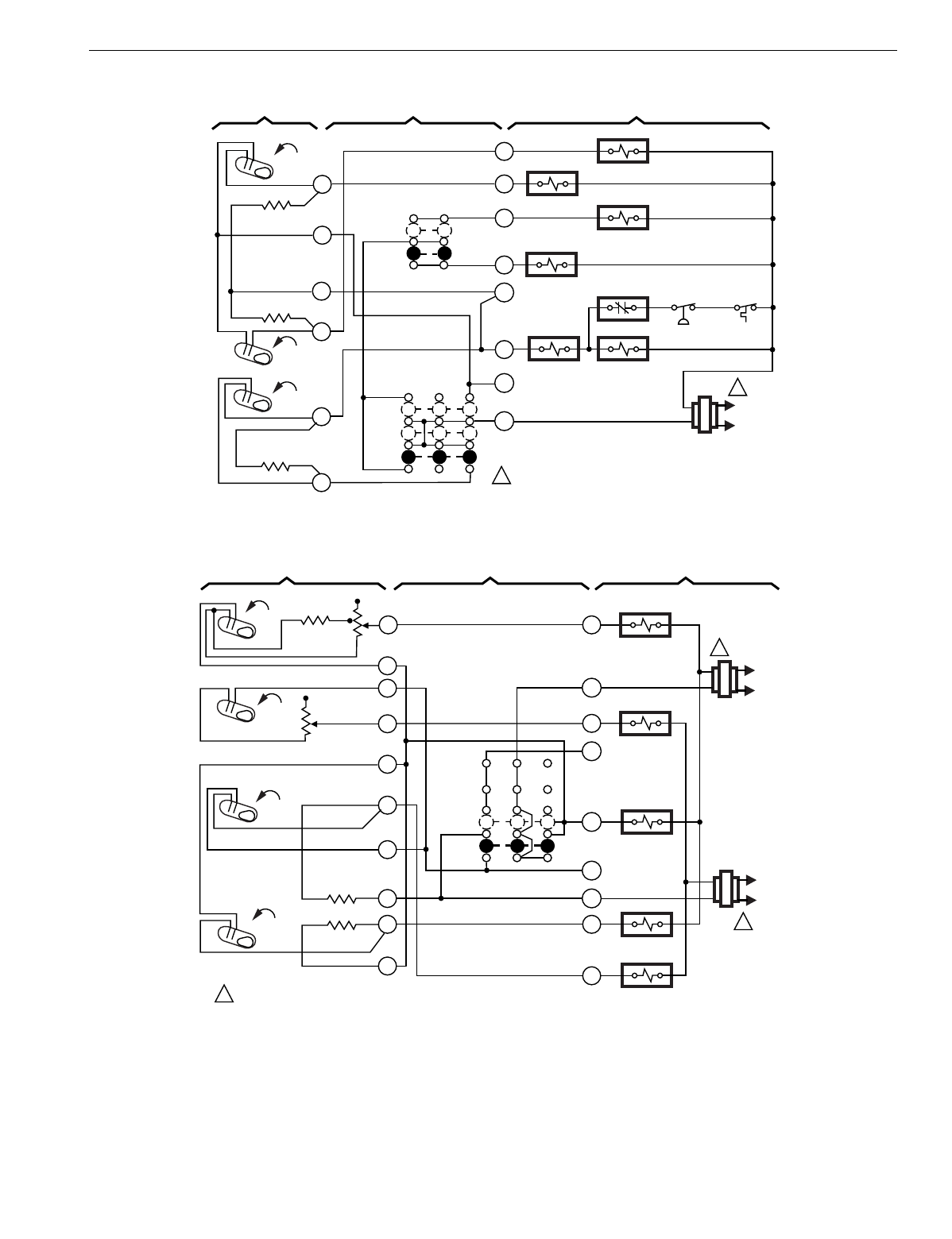
T874 MULTISTAGE THERMOSTATS AND Q674 SUBBASES
187 60-2485—8
Fig. 187. Schematic and hookup of T874C with Q674B. Used in standard applications.
Fig. 188. Schematic and hookup of T874D with Q674G. Used in standard applications.
L2
1
SYSTEM
SWITCH
OFF
H1
ANTICIPATOR
H1
FALL
1POWER SUPPLY. PROVIDE DISCONNECT MEANS
AND OVERLOAD PROTECTION AS REQUIRED. M3956
C
C1
R3
H2
RISE
R1
C1
ANTICIPATOR COOL
3
4
8
10
FALL
HEAT RELAY 1
R
R2
R5
HEAT RELAY 2
L1
(HOT)
X
5
HI SPEED
FAN RELAY
LO SPEED
FAN RELAY
HIGH
TEMP.
SWITCH
HIGH
PRESSURE
SWITCH
R4
HIGH
LOW
FAN
SWITCH
2
HEAT
H2
ANTICIPATOR
COOL
CONTACTOR
LOCKOUT
RELAY
LR
THERMOSTAT SUBBASE SYSTEM COMPONENTS
L1
(HOT)
L2
1
SYSTEM
SWITCH
H1
ANTICIPATOR
H1
FALL
1POWER SUPPLY. PROVIDE DISCONNECT MEANS
AND OVERLOAD PROTECTION AS REQUIRED. M3958
RH
C1
Y1
H2
RISE
W1
C1
ANTICIPATOR
C2
RISE
AUTO
1
4
6
8
9
10
COMPRESSOR
CONTACTOR 2
FALL
HEAT RELAY 1
RC
Y2
11
C2
ANTICIPATOR
W2
HEAT RELAY 2
COMPRESSOR
CONTACTOR 1
L1
(HOT)
L2
1
12
B
5
7
FAN RELAY
O
T
H2
ANTICIPATOR
THERMOSTAT SUBBASE SYSTEM COMPONENTS
NO
FAN
SWITCH
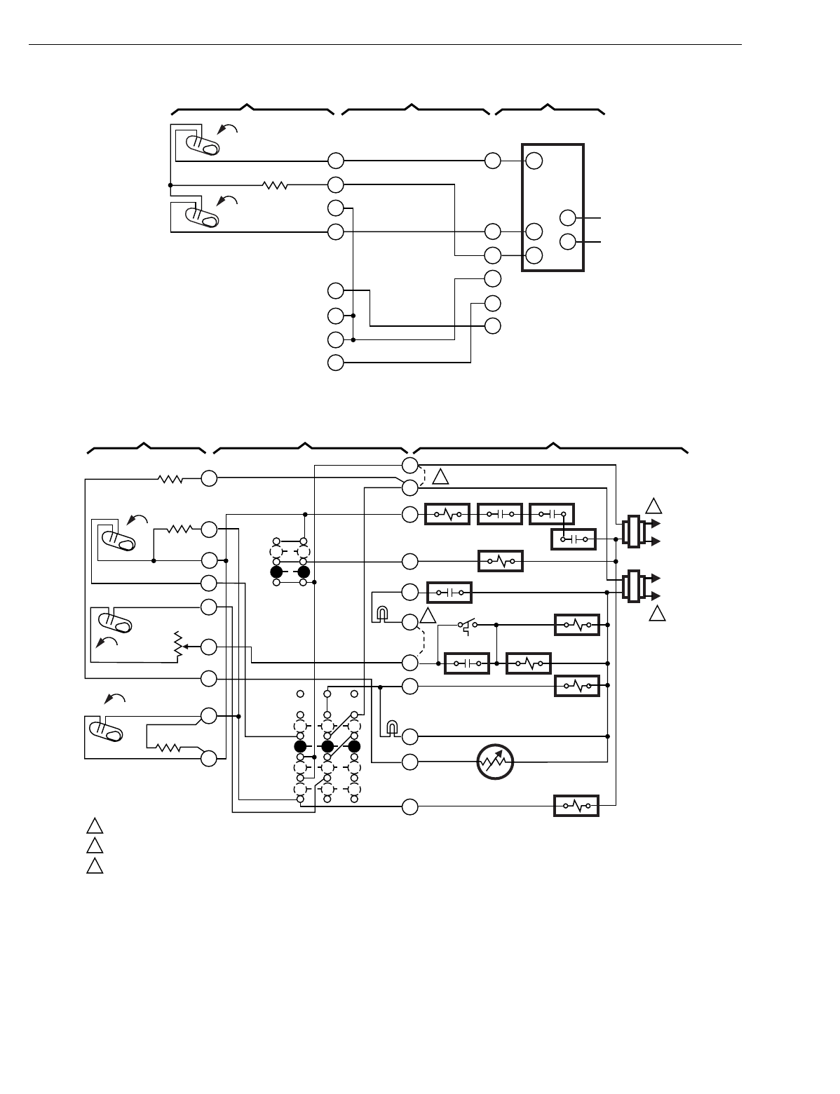
T874 MULTISTAGE THERMOSTATS AND Q674 SUBBASES
60-2485—8188
Fig. 189. Schematic and hookup of T874F with Q674D. Used in standard applications.
Fig. 190. Schematic and hookup of T874C with Q674L. Used in heat pump applications.
H1
FALL
M3960
Y1
H2
W1
1
4
6
8
9
10
FALL
Y2
11
W2
RH
B
R
Y
L1
L2
RC
5
ANTICIPATOR
M839
MOTOR
THERMOSTAT SUBBASE SYSTEM COMPONENTS
NO
FAN
SWITCH
NO
SYSTEM
SWITCH
L1
(HOT)
L2
1
FAN RELAY
SYSTEM
SWITCH
OFF
EM. HT.
H1
ANTICIPATOR
H1
FALL
1POWER SUPPLY. PROVIDE DISCONNECT MEANS AND OVERLOAD PROTECTION AS REQUIRED.
OPTIONAL REMOVABLE JUMPER TO ALLOW SINGLE SYSTEM TRANSFORMER.
WIRE JUMPER FOR SERVICE LIGHT. M3978
AUTO
ON
FAN
SWITCH
L
F
X
A
Y
H2
E
M
C1
ANTICIPATOR
C1
RISE EM. HT. LED
(YELLOW)
HEAT
2
3
4
6
8
10
SERVICE
LED (RED)
COMPRESSOR
CONTACTOR
FALL
O. D. S.
H2
ANTICIPATOR
THERMOSTAT SUBBASE SYSTEM COMPONENTS
COOL
OG
COOL CHANGEOVER
VALVE
C815A
OUTDOOR THERMISTOR
5
1
7
R
VR
V
EM. HT.
EM. HT. RELAY
IN STAT
HI PR
SERVICE
RELAY
ELEC. HT. RELAY
ELEC. HT. RELAY
RESET
2
3
3
2
1
L1
(HOT)
L2
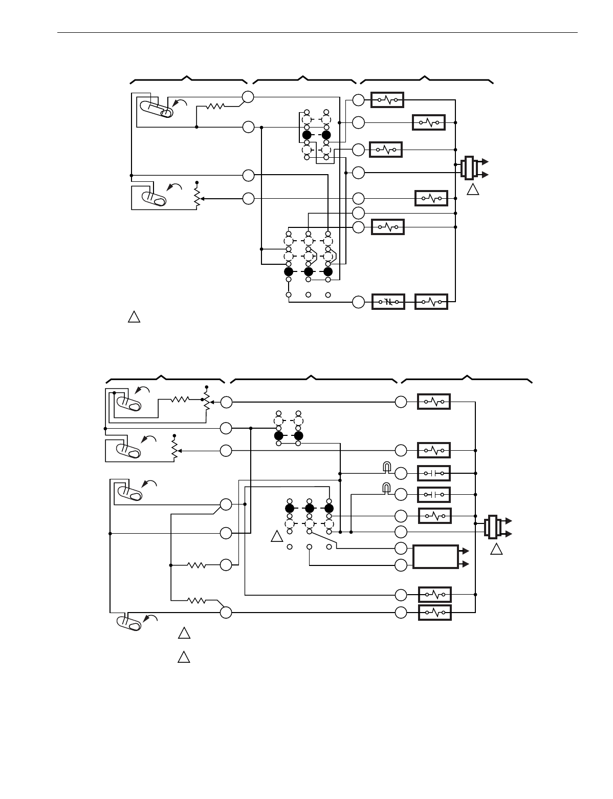
T874 MULTISTAGE THERMOSTATS AND Q674 SUBBASES
189 60-2485—8
Fig. 191. Schematic and hookup of T874R with Q674B. Used in heat pump applications.
Fig. 192. Schematic and hookup of T874D with Q674C. Used in standard applications.
L2
1
OFF
H1/C1
ANTICIPATOR
H1
FALL
1POWER SUPPLY. PROVIDE DISCONNECT MEANS AND OVERLOAD PROTECTION AS REQUIRED. M3965
Z
H2 W2
HEAT
2
4
6
FALL
AUX. HT. RELAY
"Z" RELAY
L1
(HOT)
R
FAN RELAY
Y
AUTO
CONT.
FAN
SWITCH
C
G
H2
ANTICIPATOR
3
COOL
RELAY
COOL
THERMOSTAT SUBBASE SYSTEM COMPONENTS
SYSTEM
SWITCH
C1 LO
HI
O
W1
HEAT RELAY
COOL CHANGE-
OVER VALVE
L2
1
ON
H1
ANTICIPATOR
H1
FALL
1POWER SUPPLY. PROVIDE DISCONNECT MEANS
AND OVERLOAD PROTECTION AS REQUIRED.
MOMENTARY POSITION. SPRING RETURN TO "ON" UPON SWITCH RELEASE. M3959
C1
Y1
H2
RISE
W1
C1
ANTICIPATOR
C2
RISE
AUTO
1
4
6
8
9
10
COMPRESSOR
CONTACTOR 2
FALL
HEAT RELAY 1
Y2
11
C2
ANTICIPATOR
W2
HEAT RELAY 2
COMPRESSOR
CONTACTOR 1
L1
(HOT)
RFAN RELAY
O
AUTO
OFF
SERVICE
LED (RED)
FILTER
LED
(YELLOW) X
A
G
O
2
2
MOMENTARY
CIRCUIT
H2
ANTICIPATOR
THERMOSTAT SUBBASE SYSTEM COMPONENTS
FAN
SWITCH
SYSTEM
SWITCH
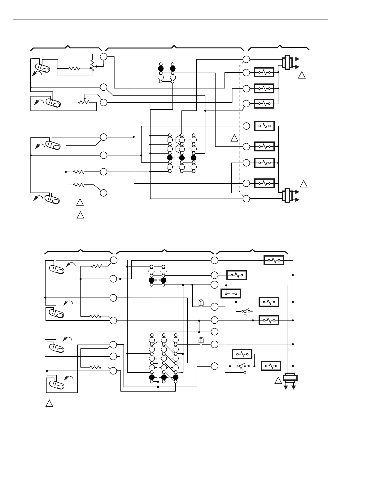
T874 MULTISTAGE THERMOSTATS AND Q674 SUBBASES
60-2485—8190
Fig. 193. Schematic and hookup of T874D with Q674E. Used in standard applications.
Fig. 194. Schematic and hookup of T874G with Q674F. Used in heat pump applications.
H1
FALL
L1
(HOT)
L2
1
RH
W1
W2
G
Y2
Y1
RC
HEAT RELAY 2
HEAT RELAY 1
OFF
HEAT
COOL
AUTO
AUTO
ON
SYSTEM
SWITCH
H1
ANTICIPATOR
C1 ANTICIPATOR
FAN
SWITCH
2
1POWER SUPPLY. PROVIDE DISCONNECT MEANS AND OVERLOAD
PROTECTION AS REQUIRED.
JUMPER RH, RC FOR SINGLE TRANSFORMER.
2
M3203B
L1
(HOT)
L2
1
FAN RELAY
O
CHANGEOVER
RELAY (COOL)
CHANGEOVER
RELAY (HEAT)
COMPRESSOR
CONTACTOR 2
COMPRESSOR
CONTACTOR 1
1
4
6
8
9
10
11
H2
FALL
C2 ANTICIPATOR
RISE
RISE
C1
C2
B
THERMOSTAT SUBBASE SYSTEM COMPONENTS
H2 ANTICIPATOR
L1
(HOT)
L2
1
FAN RELAY
SYSTEM
SWITCH
OFF
EM. HT.
H1
ANTICIPATOR
H1
FALL
1POWER SUPPLY. PROVIDE DISCONNECT MEANS AND OVERLOAD PROTECTION AS REQUIRED. M3977
AUTO
ON
FAN
SWITCH
R
G
CO
C
W1
W2
H2
RISE
E
Y1
C1
ANTICIPATOR
C1
RISE
EM. HT.
LED (RED)
HEAT
2
3
4
6
8
9
10
CHECK
LED
(GREEN)
COOL
CHANGEOVER VALVE
FALL
DR
HBTH
TDR 1
H2
ANTICIPATOR
THERMOSTAT SUBBASE SYSTEM COMPONENTS
AUTO
COOL
TDR 2
X
HPA
COMPRESSOR
CONTACTOR
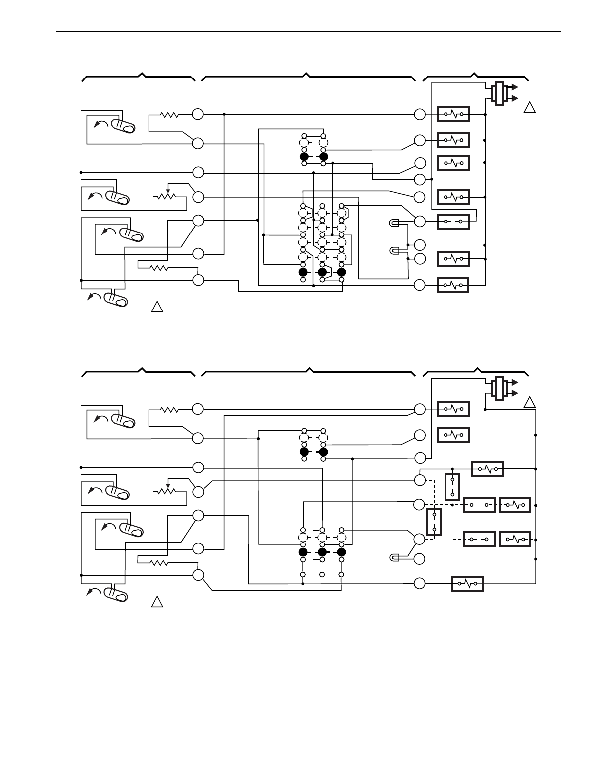
T874 MULTISTAGE THERMOSTATS AND Q674 SUBBASES
191 60-2485—8
Fig. 195. Schematic and hookup of T874G with Q674F. Used in heat pump applications.
Fig. 196. Schematic and hookup of T874G with Q674J. Used in heat pump applications.
H1
FALL
O
G
R
E
L
X
W2
FAN RELAY
COOL
CHANGEOVER
VALVE
EM. HT.
OFF
AUTO
SYSTEM
SWITCH
H1 ANTICIPATOR
C1 ANTICIPATOR
AUTO
ON
FAN SWITCH
1POWER SUPPLY. PROVIDE DISCONNECT MEANS AND OVERLOAD
PROTECTION AS REQUIRED. M2974
B
EM. HT.
RELAY
COMPRESSOR
CONTACTOR
AUX. HT. RELAY
1
4
6
8
9
10
H2
FALL
RISE
RISE
CO
C1
"B" RELAY
L1
(HOT)
L2
1
H2
ANTICIPATOR
2
EM. HT. LED
(RED)
Y
AUX.
HT. LED
(GREEN)
COOL
HEAT
THERMOSTAT SUBBASE SYSTEM COMPONENTS
COMPRESSOR
FAULT
H1
FALL
O
G
R
E
L
W2
FAN RELAY
COOL
CHANGEOVER
VALVE
OFF
ON
SYSTEM
SWITCH
H1 ANTICIPATOR
C1 ANTICIPATOR
AUTO
ON
FAN SWITCH
1POWER SUPPLY. PROVIDE DISCONNECT MEANS AND OVERLOAD
PROTECTION AS REQUIRED.
M2975
COMPRESSOR
CONTACTOR
O.D.T.
1
4
6
8
9
10
H2
FALL
RISE
RISE
CO
C1
L1
(HOT)
L2
1
H2
ANTICIPATOR
2
SUPL. HT.
LED
(RED)
Y
SUPL. HT.
H.C.R.1
H.C.R.1
H.C.R.2
H.C.R.2
H.C.R.3
C
THERMOSTAT SUBBASE SYSTEM COMPONENTS
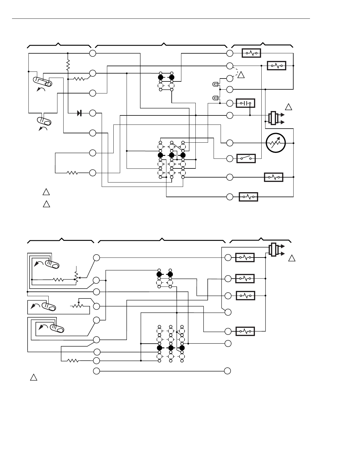
T874 MULTISTAGE THERMOSTATS AND Q674 SUBBASES
60-2485—8192
Fig. 197. Schematic and hookup of T874R with Q674L. Used in heat pump applications.
Fig. 198. Schematic and hookup of T874L with Q674E. Used in standard applications.
H1
FALL
C1
L1
(HOT)
L2
1
G
W
U
B
F
R
T
X2
O
Y
FAN RELAY
AUX. HEATER
RELAY
COMPRESSOR
MONITOR
OUTDOOR
THERMOSTAT
OUTDOOR
THERMISTOR
COOL
CHANGEOVER
VALVE
COMPRESSOR
RELAY
AUX. HT.
LED (GREEN)
EM. HT.
LED (RED)
1
2
3
4
5
6
11
FAN
SWITCH
AUTO
ON
EM. HT.
HEAT
OFF
COOL
SYSTEM
SWITCH
H2
FALL
POWER SUPPLY. PROVIDE DISCONNECT MEANS AND
OVERLOAD PROTECTION AS REQUIRED.
FIELD REMOVABLE JUMPER.
1
2
2
M2970
THERMOSTAT SUBBASE SYSTEM COMPONENTS
H1
FALL
W1
Y1
W2
COMPRESSOR
CONTACTOR
HEAT
AUTO
COOL
SYSTEM
SWITCH
H1 ANTICIPATOR AUTO
ON
FAN
SWITCH
1POWER SUPPLY. PROVIDE DISCONNECT MEANS AND OVERLOAD PROTECTION AS REQUIRED.
M2976
R
STAGE 2
HEAT RELAY
1
4
6
7
9
10
H2
FALL
C2 ANTICIPATOR
RISE C1
STAGE 1 HEAT RELAY
L1
(HOT)
L2
1
H2
ANTICIPATOR
G
FAN RELAY
3
8
OFF
THERMOSTAT SUBBASE SYSTEM COMPONENTS
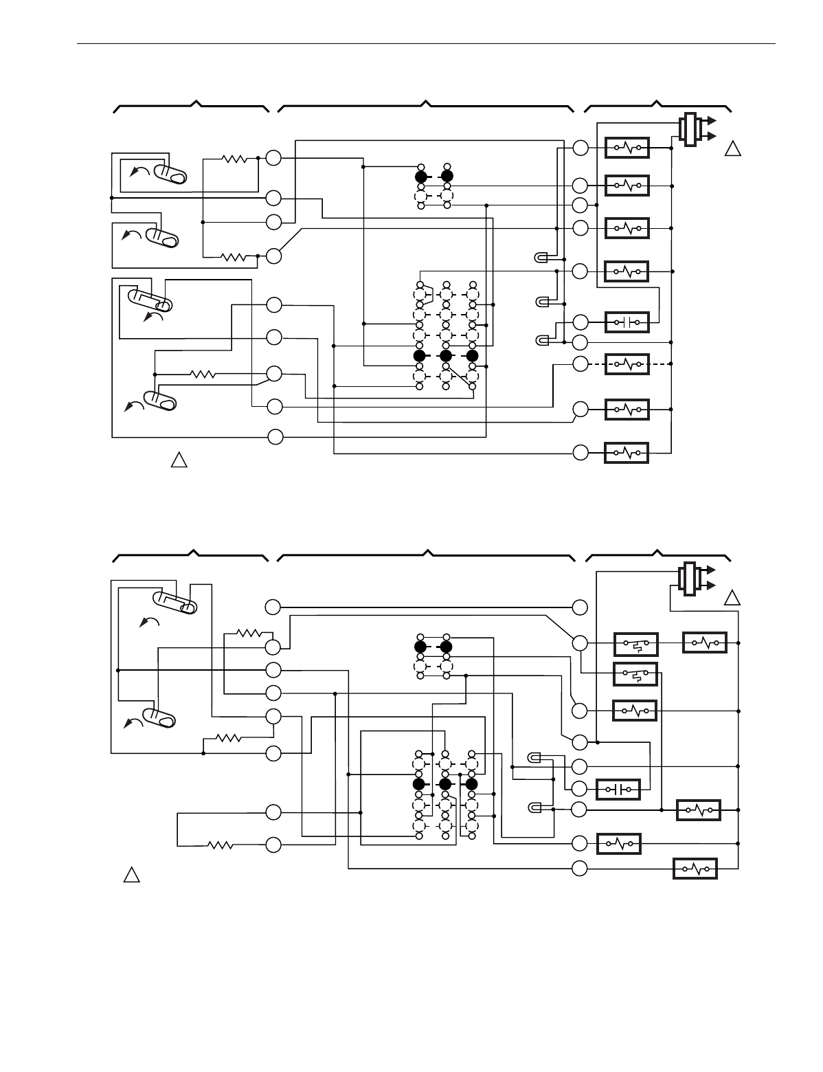
T874 MULTISTAGE THERMOSTATS AND Q674 SUBBASES
193 60-2485—8
Fig. 199. Schematic and hookup of T874G with Q674F. Used in heat pump applications.
Fig. 200. Schematic and hookup of T874R with Q674L. Used in heat pump applications.
H1
FALL
O
G
R
E
X
FAN RELAY
W3 RELAY
EM. HT.
OFF
AUTO
SYSTEM
SWITCH
H1 ANTICIPATOR
C1 ANTICIPATOR
AUTO
ON
FAN SWITCH
1POWER SUPPLY. PROVIDE DISCONNECT MEANS AND OVERLOAD
PROTECTION AS REQUIRED. M2977
B
COMPRESSOR
CONTACTOR
AUX. HT. RELAY
4
5
8
9
10
H2
FALL
RISE
C1
L1
(HOT)
L2
1
H2
ANTICIPATOR
2
CHECK
LED
(RED)
Y
AUX. HT. LED
(GREEN)
COOL
HEAT
W3
W2
EM. HT. RELAY
COMPRESSOR
FAULT
L
HEAT CHANGEOVER
VALVE
COOL CHANGEOVER
RELAY
3
11
12
CO
RISE
EM. HT.
LED (RED)
THERMOSTAT SUBBASE SYSTEM COMPONENTS
T
G
R
Z
X
W1
FAN RELAY
EM. HT.
OFF
SYSTEM
SWITCH
AUTO
ON
FAN SWITCH
1POWER SUPPLY. PROVIDE DISCONNECT MEANS AND OVERLOAD PROTECTION AS REQUIRED. M2978
COMPRESSOR
CONTACTOR
SERVICE
1
3
6
11
L1
(HOT)
L2
1
2
SERVICE
LED
(YELLOW)
Y
EM. HT.
LED (RED)
COOL
HEAT
W2
OUTDOOR
THERMOSTAT
SEQ 2
K
SEQ 1
HEAT CHANGEOVER
VALVE
H2 ANTICIPATOR
RISE
H2
H1 C1
FALL
4
5
C1 ANTICIPATOR
12
H1 ANTICIPATOR
THERMOSTAT SUBBASE SYSTEM COMPONENTS
OUTDOOR
THERMOSTAT
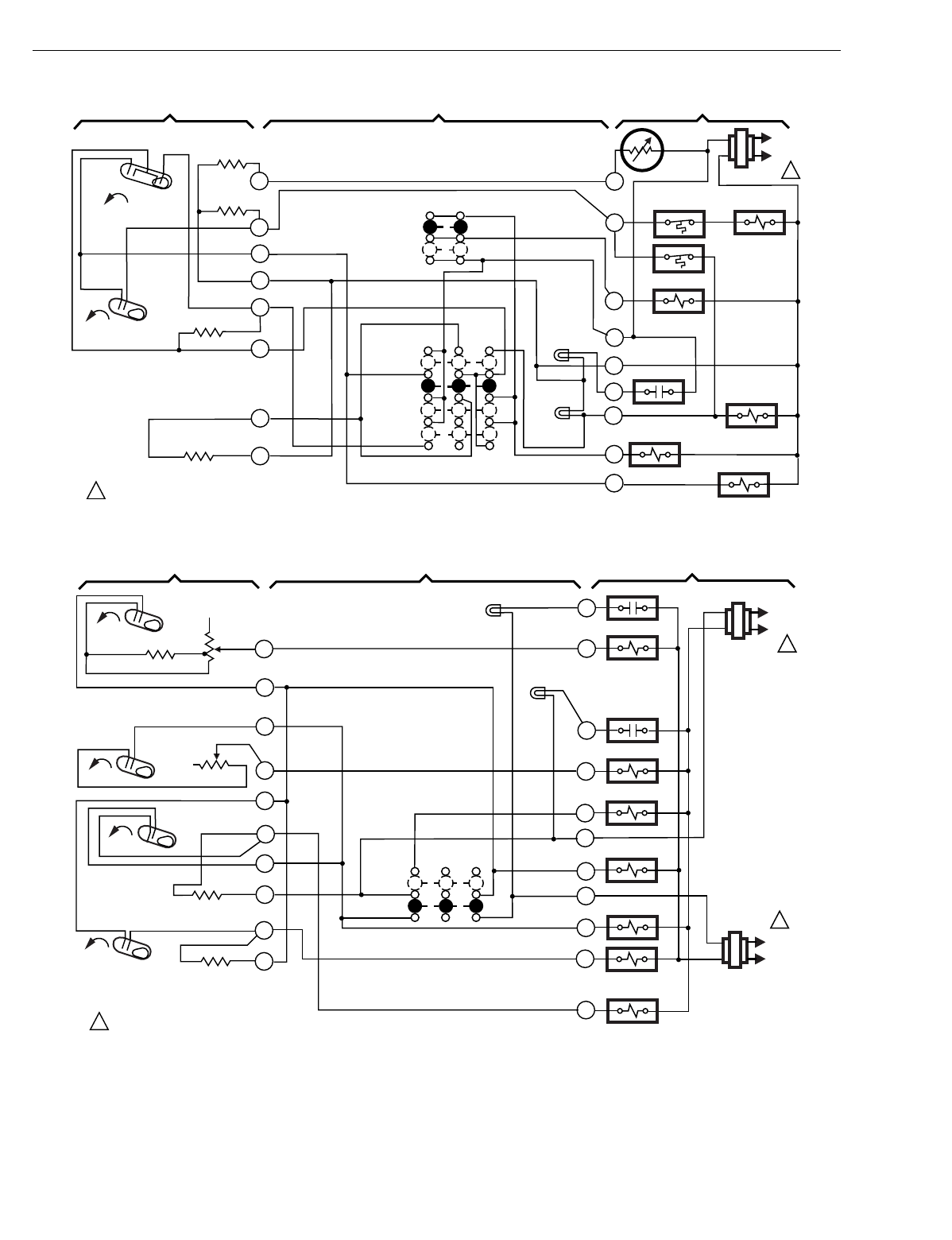
T874 MULTISTAGE THERMOSTATS AND Q674 SUBBASES
60-2485—8194
Fig. 201. Schematic and hookup of T874R with Q674L. Used in heat pump applications.
Fig. 202. Schematic and hookup of T874D with Q674G. Used in standard applications.
T
G
R
Z
X
W1
FAN RELAY
EM. HEAT
OFF
SYSTEM
SWITCH
AUTO
ON
FAN SWITCH
1POWER SUPPLY. PROVIDE DISCONNECT MEANS AND OVERLOAD PROTECTION AS REQUIRED. M2979
COMPRESSOR
CONTACTOR
SERVICE
1
3
6
11
L1
(HOT)
L2
1
2
SERVICE
LED
(YELLOW)
Y
EM. HT.
LED (RED)
COOL
HEAT
W2
OUTDOOR
THERMOSTAT SEQ 2
K
SEQ 1
HEAT CHANGEOVER
VALVE
H2
ANTICIPATOR
RISE
H2
H1 C1
RISE
4
5
C1 ANTICIPATOR
12
H1 ANTICIPATOR
RESET
THERMOSTAT SUBBASE SYSTEM COMPONENTS
C815A
OUTDOOR
THERMISTOR
OUTDOOR
THERMOSTAT
H1
FALL
W1
W2
T
RC
RH
O
FAN RELAY B
HEAT RELAY 1
AUTO
OFF
SYSTEM
SWITCH
H1 ANTICIPATOR
C1 ANTICIPATOR
NO
FAN
SWITCH
1POWER SUPPLY. PROVIDE DISCONNECT MEANS AND OVERLOAD
PROTECTION AS REQUIRED M2980
THERMOSTAT SUBBASE SYSTEM COMPONENTS
L1
(HOT)
L2
1
COMPRESSOR
CONTACTOR 2
COMPRESSOR
CONTACTOR 1
1
4
6
7
9
10
12
H2
FALL
C2 ANTICIPATOR
RISE
RISE
C1
C2
Y1
Y2
HEAT RELAY 2
L1
(HOT)
L2
1
H2
ANTICIPATOR
A2
"T" RELAY
B
FAN RELAY O
A1
5
8
11
SERVICE
LED (RED)
SERVICE
LED (RED)
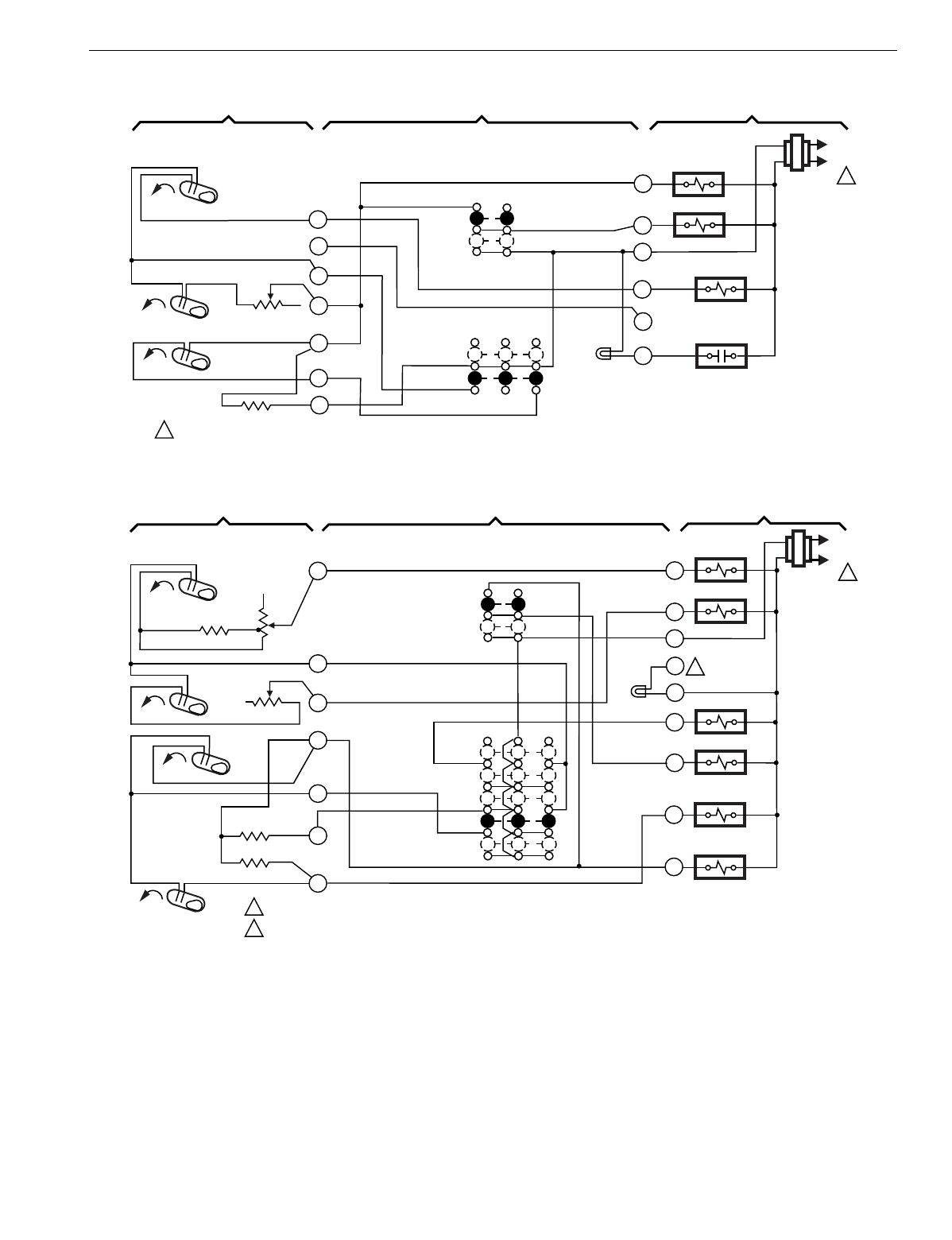
T874 MULTISTAGE THERMOSTATS AND Q674 SUBBASES
195 60-2485—8
Fig. 203. Schematic and hookup of T874L with Q674C. Used in heat pump applications.
Fig. 204. Schematic and hookup of T874D with Q674F. Used in standard applications.
CO
FALL
Y
R
W
OFF
SYSTEM
SWITCH
C1 ANTICIPATOR
AUTO
ON
FAN SWITCH
1POWER SUPPLY. PROVIDE DISCONNECT MEANS AND OVERLOAD PROTECTION AS REQUIRED.
M2981
THERMOSTAT SUBBASE SYSTEM COMPONENTS
4
6
8
9
10
H1
FALL
RISE C1
H1 ANTICIPATOR
2
COMP.
FAULT
(RED)
AUTO
COMPRESSOR
CONTACTOR
L1
(HOT)
L2
1
G
FAN RELAY
W2
HEAT CHANGEOVER
VALVE
A
COMPRESSOR
FAULT
3
H1
FALL
W1
G
W2
B
HEAT RELAY 1
HEAT
OFF
COOL
SYSTEM
SWITCH
H1 ANTICIPATOR
C1 ANTICIPATOR
AUTO
ON
FAN
SWITCH
1
2
POWER SUPPLY. PROVIDE DISCONNECT MEANS AND OVERLOAD PROTECTION AS REQUIRED.
LED IS NOT LABELED. JUMPER W2 TO X FOR AUXILIARY HEAT INDICATION. JUMPER E TO X FOR
EMERGENCY HEAT INDICATION. CONNECT SYSTEM MONITOR TO X TO IDENTIFY WHEN SYSTEM
NEEDS TO BE CHECKED. M2982A
THERMOSTAT SUBBASE SYSTEM COMPONENTS
R
EM. HT. RELAY
COMPRESSOR
CONTACTOR 2
COMPRESSOR
CONTACTOR 1
1
4
6
8
9
10
11
H2
FALL
C2 ANTICIPATOR
RISE
RISE
C1
C2
Y1
Y2
HEAT RELAY 2
L1
(HOT)
L2
1
2
LED
(RED)
H2
ANTICIPATOR
AUTO
EM. HT.
X
E
FAN RELAY
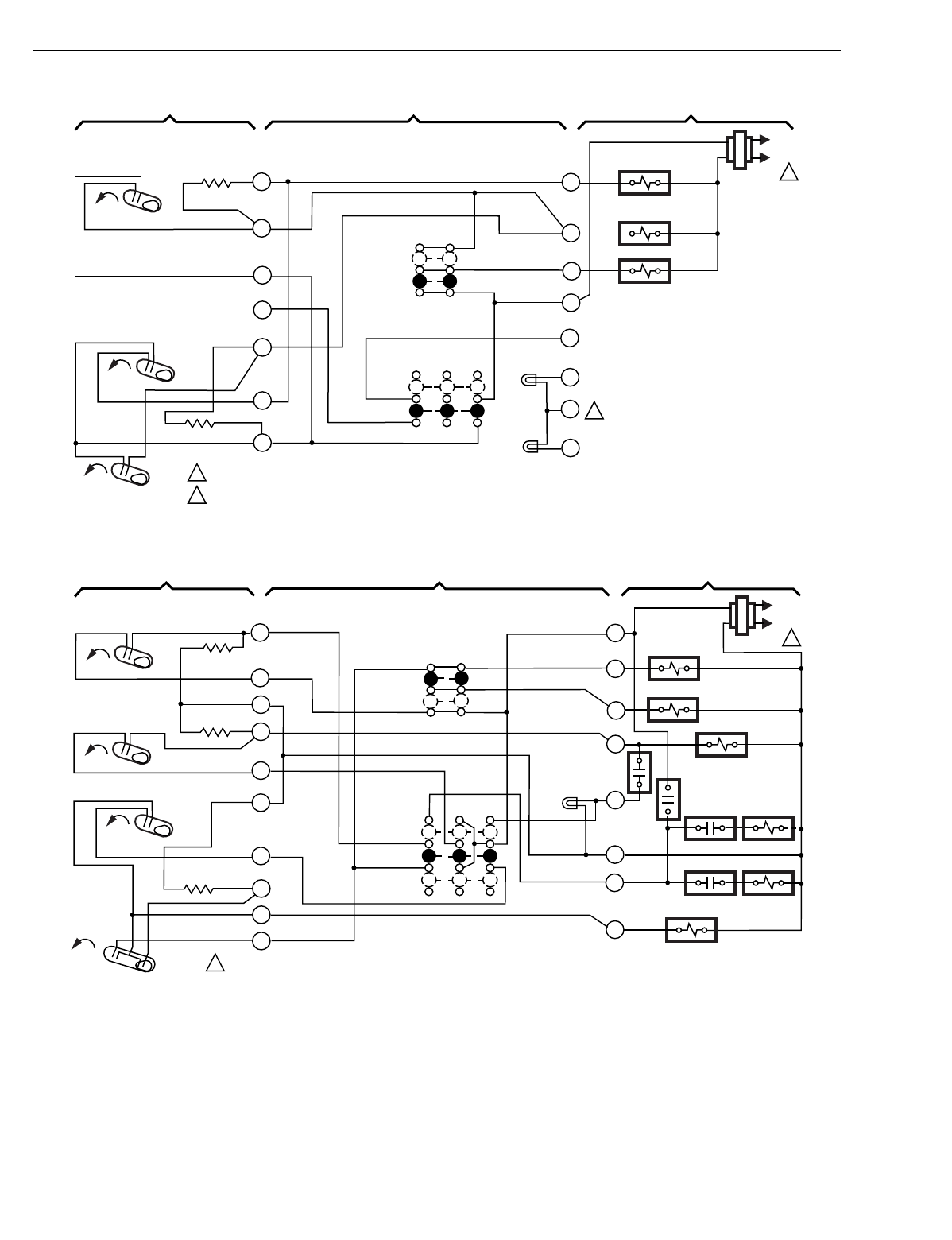
T874 MULTISTAGE THERMOSTATS AND Q674 SUBBASES
60-2485—8196
Fig. 205. Schematic and hookup of T874H with Q674C. Used in heat pump applications.
Fig. 206. Schematic and hookup of T874J with Q674J. Used in heat pump applications.
H1
FALL
G
R
X1
L
Y2
OFF
AUTO
SYSTEM
SWITCH
H1 ANTICIPATOR
C1 ANTICIPATOR
AUTO
ON
FAN SWITCH
1POWER SUPPLY. PROVIDE DISCONNECT MEANS AND OVERLOAD PROTECTION AS REQUIRED.
LEDS ON SOME MODELS.
M2983
THERMOSTAT SUBBASE SYSTEM COMPONENTS
4
6
8
9
10
RISE
RISE
CO
C1
2
LED
(RED)
Y1
C
FAN RELAY
COMPRESSOR
CONTACTOR
L1
(HOT)
L2
1
3
X2
LED
(RED)
2
2
COOL CHANGEOVER
VALVE
H1
FALL Y
G
R
E
L
W2
FAN RELAY
COMPRESSOR
CONTACTOR
OFF
ON
SYSTEM
SWITCH
H1 ANTICIPATOR
C1 ANTICIPATOR
AUTO
ON
FAN SWITCH
1POWER SUPPLY. PROVIDE DISCONNECT MEANS AND OVERLOAD
PROTECTION AS REQUIRED. M2984
THERMOSTAT SUBBASE SYSTEM COMPONENTS
COOL
CHANGEOVER
VALVE
O.D.T.
4
6
8
9
10
H2
FALL
RISE CO
L1
(HOT)
L2
1
H2
ANTICIPATOR
SUPL. HT.
LED (RED)
O
H.C.R.1
H.C.R.1
H.C.R.2
H.C.R.2
H.C.R.3
C
2
3
5
11
12
C1 CO
SUPL. HT.
RISE
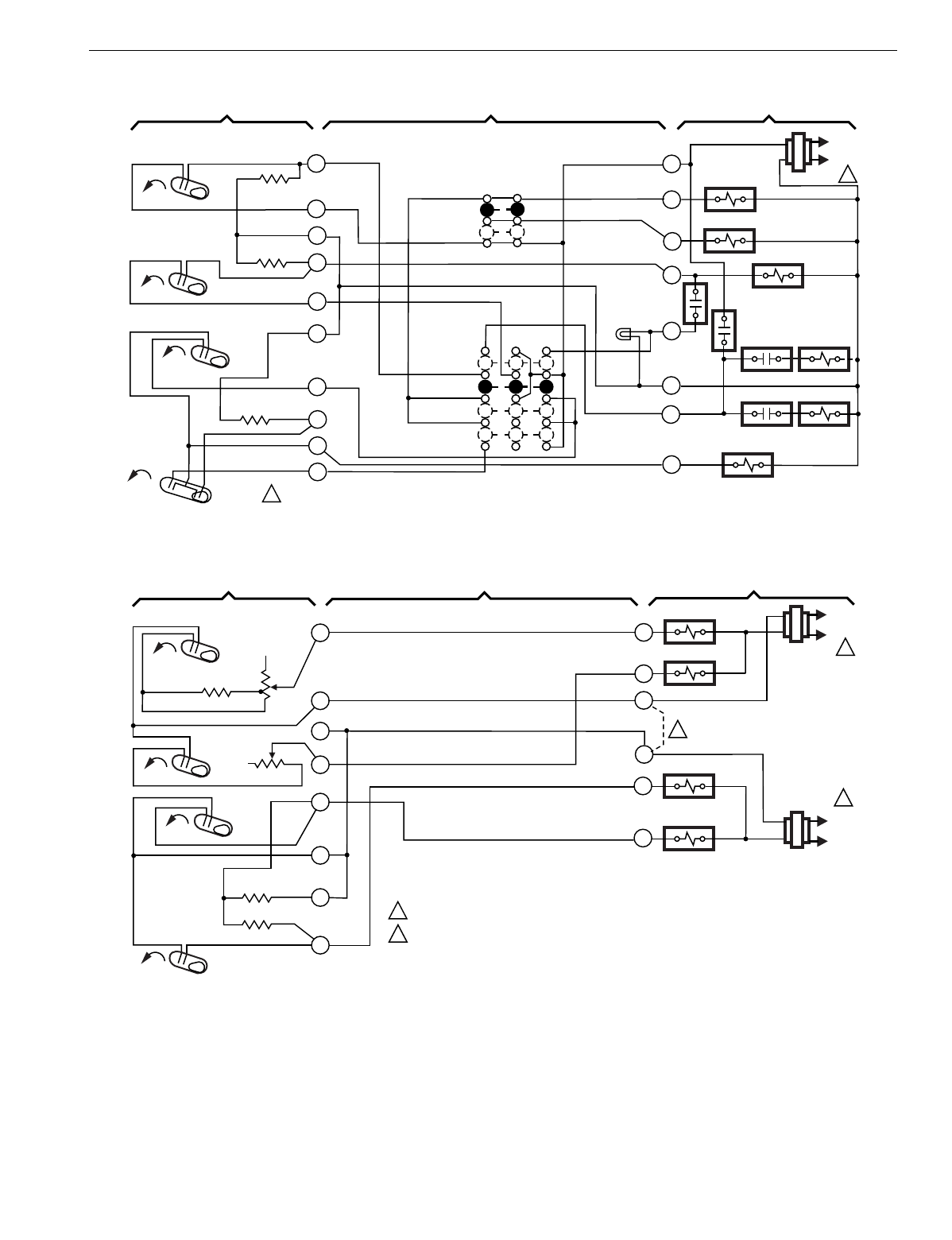
T874 MULTISTAGE THERMOSTATS AND Q674 SUBBASES
197 60-2485—8
Fig. 207. Schematic and hookup of T874J with Q674L. Used in heat pump applications.
Fig. 208. Schematic and hookup of T874D with Q674D. Used in standard applications.
H1
FALL Y
G
R
E
L
W2
FAN RELAY
COMPRESSOR
CONTACTOR
OFF
COOL
SYSTEM
SWITCH
H1 ANTICIPATOR
C1 ANTICIPATOR
AUTO
ON
FAN SWITCH
1POWER SUPPLY. PROVIDE DISCONNECT MEANS AND OVERLOAD
PROTECTION AS REQUIRED.
M2985
THERMOSTAT SUBBASE SYSTEM COMPONENTS
COOL CHANGEOVER
VALVE
O.D.T.
4
6
8
9
10
H2
FALL
RISE CO
L1
(HOT)
L2
1
H2
ANTICIPATOR
SUPL. HT.
LED (RED)
O
H.C.R.1
H.C.R.1
H.C.R.2
H.C.R.2
H.C.R.3
C
2
3
5
11
12
C1 CO
SUPL. HT.
RISE
HEAT
H1
FALL
W1
W2
HEAT RELAY 1
H1 ANTICIPATOR
C1 ANTICIPATOR 1POWER SUPPLY. PROVIDE DISCONNECT MEANS AND OVERLOAD PROTECTION AS REQUIRED.
RC-RH REMOVABLE JUMPER WHEN SPECIFIED. M2986
THERMOSTAT SUBBASE SYSTEM COMPONENTS
COMPRESSOR
CONTACTOR 2
COMPRESSOR
CONTACTOR 1
1
5
6
8
9
10
11
H2
FALL
C2 ANTICIPATOR
RISE
RISE
C1
C2
Y1
Y2
HEAT RELAY 2
L1
(HOT)
L2
1
H2
ANTICIPATOR
L1
(HOT)
L2
1
RC
RH
2
4
NO
FAN
SWITCH
NO
SYSTEM
SWITCH
2
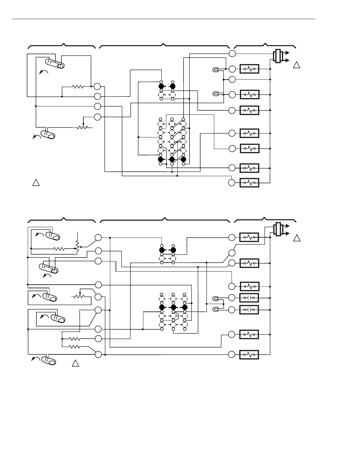
T874 MULTISTAGE THERMOSTATS AND Q674 SUBBASES
60-2485—8198
Fig. 209. Schematic and hookup of T874R with Q674L. Used in heat pump applications.
Fig. 210. Schematic and hookup of T874Y with Q674E. Used in heat pump applications.
L
EM. HEAT
OFF
SYSTEM
SWITCH
AUTO
ON
FAN SWITCH
1POWER SUPPLY. PROVIDE DISCONNECT MEANS AND OVERLOAD PROTECTION AS REQUIRED.
THERMOSTAT SUBBASE SYSTEM COMPONENTS
3
6
2
AUX. HT.
LED
(GREEN)
Y
EM. HT.
LED (RED)
COOL
HEAT
H2 ANTICIPATOR
RISE
H2
H1 C1
FALL
4
H1/C1
ANTICIPATOR
G
W2
B
R
EM. HT. RELAY
COOL
CHANGEOVER
VALVE
COMPRESSOR
CONTACTOR
’"B" RELAY
EM. HT.
RELAY
L1
(HOT)
L2
1
X
E
FAN RELAY
AUX. HT. RELAY
O
M2987
H1
FALL G
B
HEAT
OFF
COOL
SYSTEM
SWITCH
H1 ANTICIPATOR
C1 ANTICIPATOR
AUTO
ON
FAN
SWITCH
1POWER SUPPLY. PROVIDE DISCONNECT MEANS AND OVERLOAD PROTECTION AS REQUIRED. M2988
THERMOSTAT SUBBASE SYSTEM COMPONENTS
R
COMPRESSOR
CONTACTOR 2
COMPRESSOR
CONTACTOR 1
1
3
6
8
9
10
11
H2
FALL
C2 ANTICIPATOR
RISE
RISE
C1
C2
Y1
Y2
L1
(HOT)
L2
1
FILTER
LED
(YELLOW)
H2
ANTICIPATOR
AUTO
FAN RELAY
HCO
FALL
CCO
2
4
O
L
F
COOL
CHANGEOVER
VALVE
HEAT
CHANGEOVER
VALVE
RESET
LED
(RED)
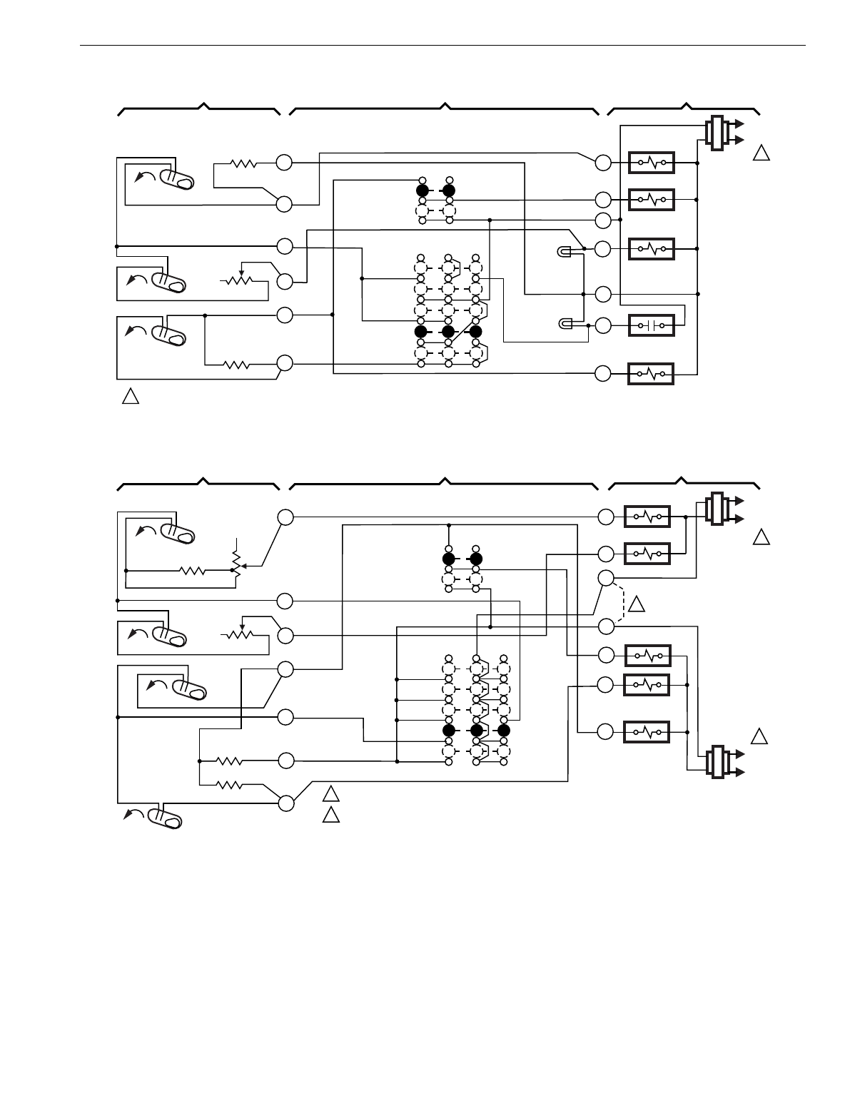
T874 MULTISTAGE THERMOSTATS AND Q674 SUBBASES
199 60-2485—8
Fig. 211. Schematic and hookup of T874G with Q674F. Used in standard applications.
Fig. 212. Schematic and hookup of T874A with Q674E. Used in standard applications.
H1
FALL
G
R
L
X
W2
FAN RELAY
W1 RELAY
EM. HT.
OFF
AUTO
SYSTEM
SWITCH
H1 ANTICIPATOR
C1
ANTICIPATOR
AUTO
ON
FAN SWITCH
1POWER SUPPLY. PROVIDE DISCONNECT MEANS AND OVERLOAD PROTECTION AS REQUIRED. M2989
THERMOSTAT SUBBASE SYSTEM COMPONENTS
W1
COMPRESSOR
FAULT
AUX. HT. RELAY
3
4
6
8
10
H2
FALL
RISE C1
L1
(HOT)
L2
1
H2
ANTICIPATOR
2
EM. HT.
LED (RED)
Y1
AUX. HT.
LED
(GREEN)
COOL
HEAT
COMPRESSOR
CONTACTOR
H1
FALL
W1
W2
HEAT RELAY 1
H1 ANTICIPATOR
C1 ANTICIPATOR
1POWER SUPPLY. PROVIDE DISCONNECT MEANS AND OVERLOAD PROTECTION AS REQUIRED.
RC -RH REMOVABLE JUMPER WHEN SPECIFIED. M2990
THERMOSTAT SUBBASE SYSTEM COMPONENTS
COMPRESSOR
CONTACTOR 2
COMPRESSOR
CONTACTOR 1
1
6
8
9
10
11
H2
FALL
C2 ANTICIPATOR
RISE
RISE
C1
C2
Y1
Y2
HEAT RELAY 2
L1
(HOT)
L2
1
H2
ANTICIPATOR
L1
(HOT)
L2
1
RC
RH
2
4
2
G
FAN RELAY
HEAT
AUTO
COOL
SYSTEM
SWITCH
AUTO
ON
FAN
SWITCH
OFF
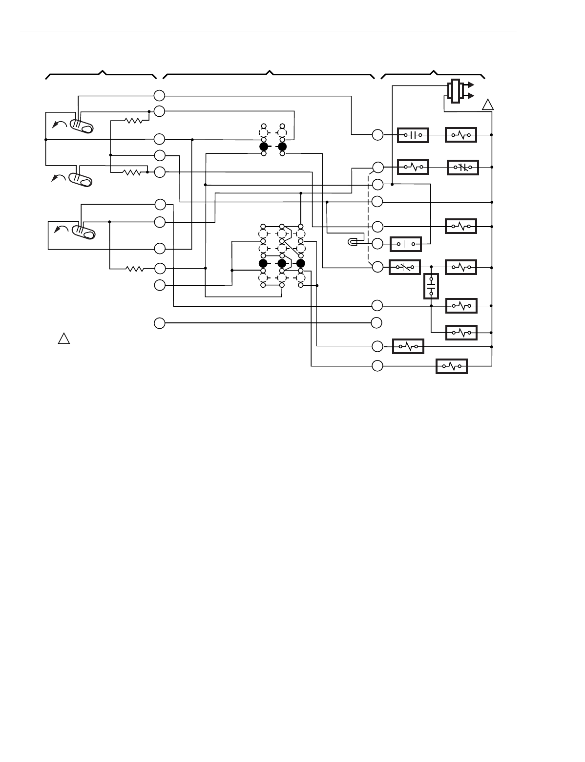
T874 MULTISTAGE THERMOSTATS AND Q674 SUBBASES
60-2485—8200
Fig. 213. Schematic and hookup of T874L with Q674C. Used in heat pump applications.
H1
FALL
Y
H1
R
LCOMPRESSOR
CONTACTOR
RELAY 1
N.O. 2
HIGH
ON
SYSTEM
SWITCH
H1 ANTICIPATOR
C1 ANTICIPATOR
AUTO
OFF
FAN
SWITCH
1POWER SUPPLY. PROVIDE DISCONNECT MEANS AND OVERLOAD
PROTECTION AS REQUIRED.
M2991
THERMOSTAT SUBBASE SYSTEM COMPONENTS
COOL
CHANGEOVER
VALVE
4
1
8
9
10
H2
FALL
RISE CO
L1
(HOT)
L2
1
H2 ANTICIPATOR
CHECK
LED (RED)
C
2
3
5
LO
MED
COMPRESSOR
CONTACTOR
S1
RELAY
S1
RELAY N.C.
H2
AUX. HT. RELAY
R1 RELAY N.C. 1
R1 RELAY
K1 RELAY
G1
K2 RELAY
G2
R2
RELAY
N.O 1
7
O
FIELD
REMOVABLE
JUMPER
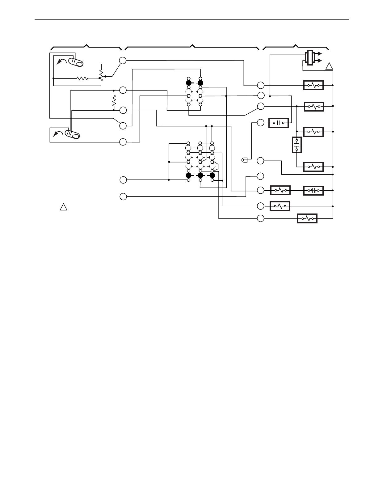
T874 MULTISTAGE THERMOSTATS AND Q674 SUBBASES
201 60-2485—8
Fig. 214. Schematic and hookup of T874A with Q674B. Used in standard applications.
H1
R
L
COMPRESSOR
CONTACTOR
HIGH
ON
SYSTEM
SWITCH
COOL
OFF
FAN
SWITCH
1POWER SUPPLY. PROVIDE DISCONNECT MEANS AND OVERLOAD
PROTECTION AS REQUIRED.
M2992
THERMOSTAT SUBBASE SYSTEM COMPONENTS
COOL
CHANGEOVER
VALVE
4
1
L1
(HOT)
L2
1
CHECK
LED (RED)
O
2
3
5
LO
MED
AUX. HT. RELAY
R1 RELAY
K1 RELAY
G1
K2 RELAY
G2
R2
RELAY
N.O. 1
HEAT
C
Y
COMPRESSOR
CONTACTOR
H1
FALL
H1 ANTICIPATOR
C1 ANTICIPATOR
C1
RISE
S1 RELAY N.C.
11
12
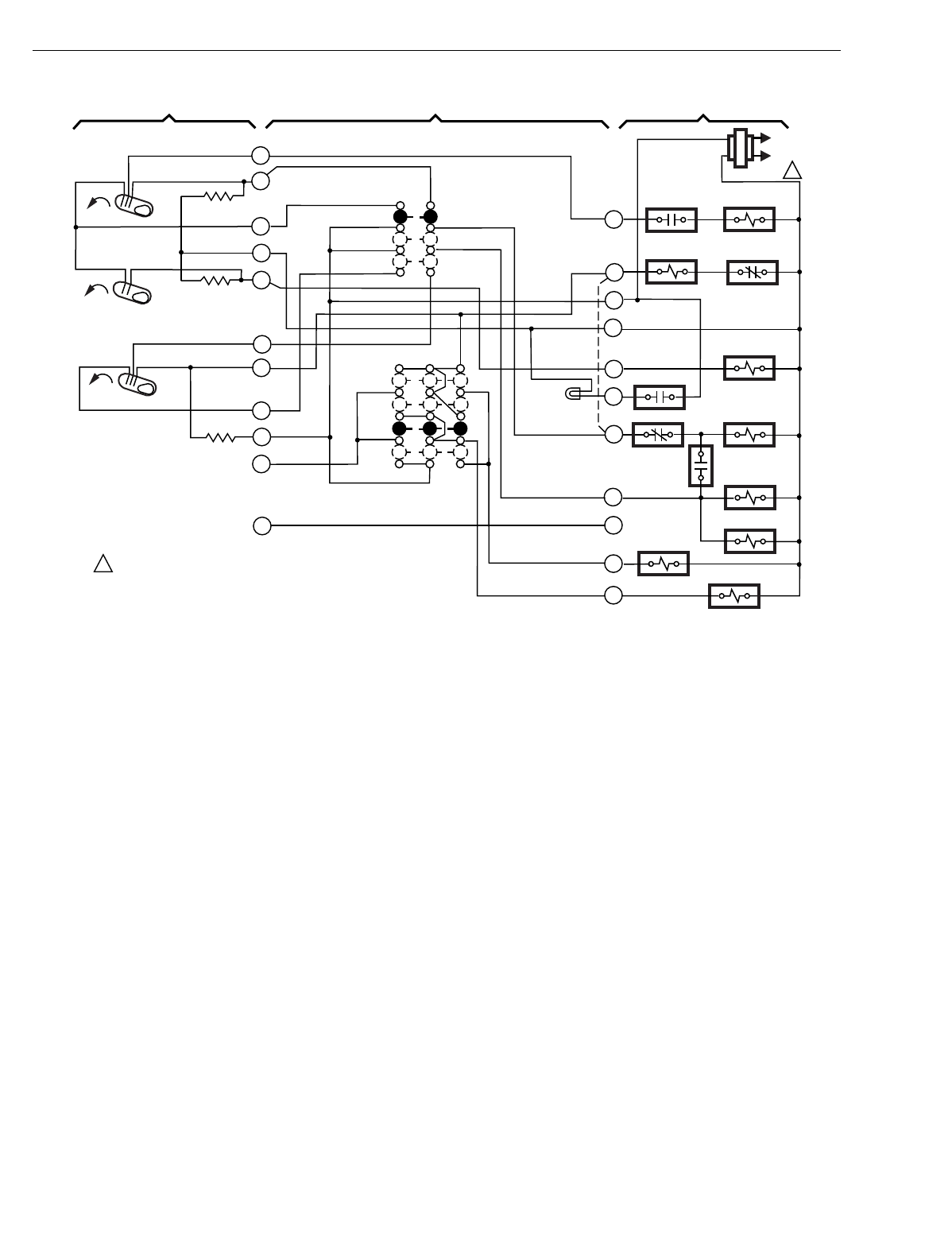
T874 MULTISTAGE THERMOSTATS AND Q674 SUBBASES
60-2485—8202
Fig. 215. Schematic and hookup of T874L with Q674B. Used in heat pump applications.
H1
FALL
Y
H1
R
LCOMPRESSOR
CONTACTOR
RELAY 1
N.O. 2
HIGH
ON
SYSTEM
SWITCH
H1 ANTICIPATOR
C1 ANTICIPATOR
COOL
OFF
FAN
SWITCH
1POWER SUPPLY. PROVIDE DISCONNECT MEANS AND OVERLOAD
PROTECTION AS REQUIRED.
M2993
THERMOSTAT SUBBASE SYSTEM COMPONENTS
COOL
CHANGEOVER
VALVE
4
1
8
9
10
H2
FALL
RISE C1
L1
(HOT)
L2
1
H2 ANTICIPATOR
CHECK
LED (RED)
C
2
3
5
LO
MED
COMPRESSOR
CONTACTOR
S1
RELAY
S1
RELAY N.C.
H2
AUX. HT. RELAY
R1 RELAY N.C. 1
R1 RELAY
K1 RELAY
G1
K2 RELAY
G2
R2
RELAY
N.O. 1
7
O
FIELD
REMOVABLE
JUMPER
HEAT
11
12
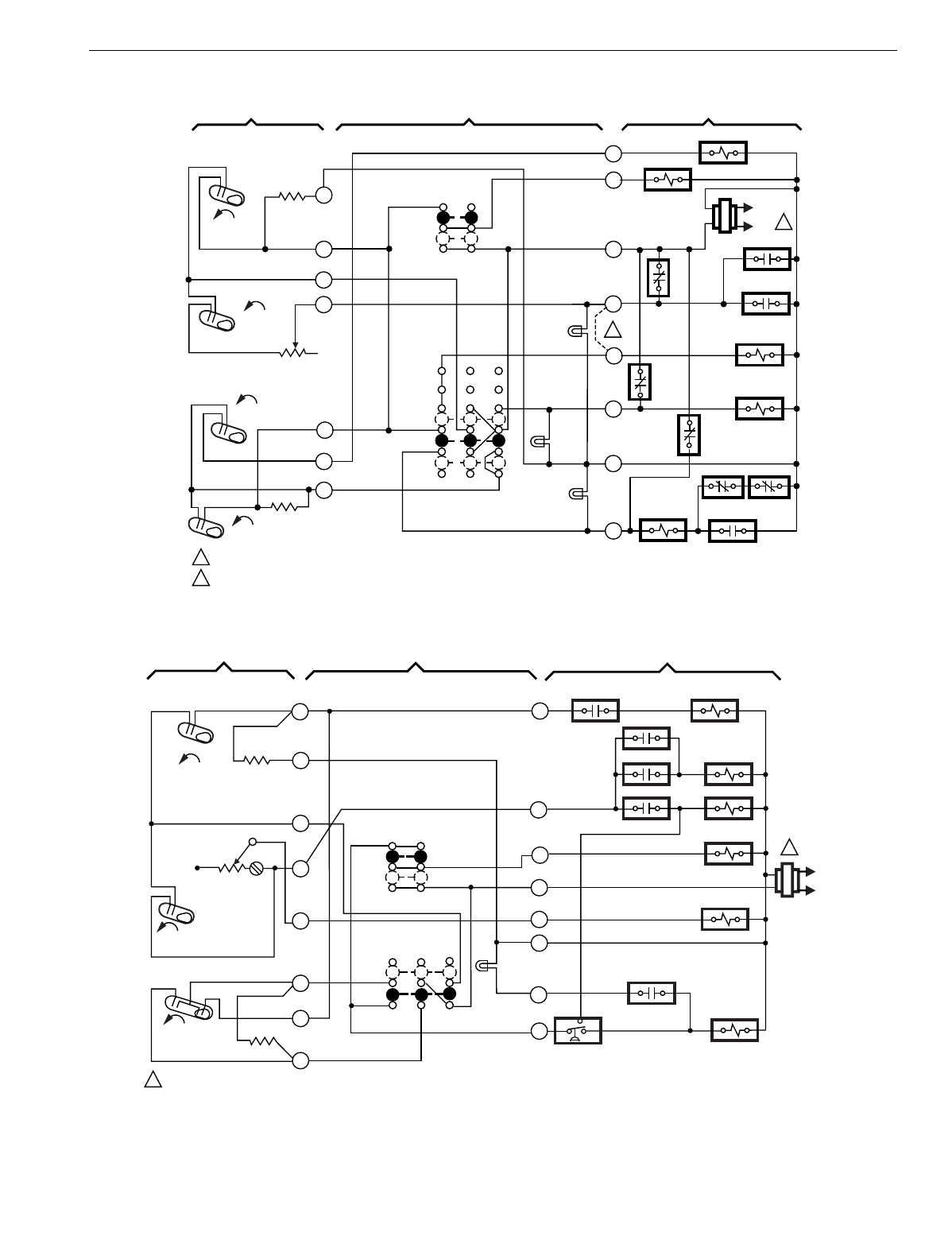
T874 MULTISTAGE THERMOSTATS AND Q674 SUBBASES
203 60-2485—8
Fig. 216. Schematic and hookup of T874G with Q674J. Used in heat pump applications.
Fig. 217. Schematic and hookup of T874N with Q674C. Used in heat pump applications.
H1
FALL
H2
FALL
CO
RISE
C1 RISE
L1
(HOT)
L2
1
2
1
2
POWER SUPPLY. PROVIDE DISCONNECT MEANS AND OVERLOAD PROTECTION AS REQUIRED.
REMOVE JUMPER FOR INDEPENDENT CONTROL OF W1 AND E TERMINALS.
THERMOSTAT SUBBASE SYSTEM COMPONENTS
H1
ANTICIPATOR
H2 ANTICIPATOR
C1
ANTICIPATOR
SYSTEM
SWITCH
FAN
SWITCH
AUTO
ON
OFF
EM. HT.
AUTO
EM. HT.
RELAY
COOL CHANGEOVER
VALVE
COMPRESSOR
CONTACTOR
M1629
1
2
4
6
8
9
10
Y
C
X
E
W1
R
G
O
AUX. HT.
LED
(YELLOW)
CHECK
LED
(RED)
SYSTEM
LED
(GREEN)
4R
HPS 4R
5R 4R
4R
SEQ 1
SEQ 2
3R
FAN RELAY
M5900
L1
(HOT)
L2
1
Y
L
X
W2
W3
R
ODT
EHR
HEAT CHANGEOVER VALVE
EHR
COMPRESSOR
CONTACTOR
OPTIONAL
COMPRESSOR FAILURE
CHECK LED
(GREEN)
FAN SWITCH
ON
AUTO
SYSTEM
SWITCH
OFF
AUTO
H2
FALL
H1
FALL
1
4
5
6
H1 ANTICIPATOR
H2
ANTICIPATOR
1POWER SUPPLY. PROVIDE DISCONNECT MEANS AND OVERLOAD PROTECTION AS REQUIRED.
THERMOSTAT SUBBASE SYSTEM COMPONENTS
C1
RISE
8
9
C1 ANTICIPATOR
W1
D. P.
G
HEAT
CONTACTOR #2
FAN RELAY
2
10
CO
HEAT
CONTACTOR #3
HEAT CONTACTOR #1
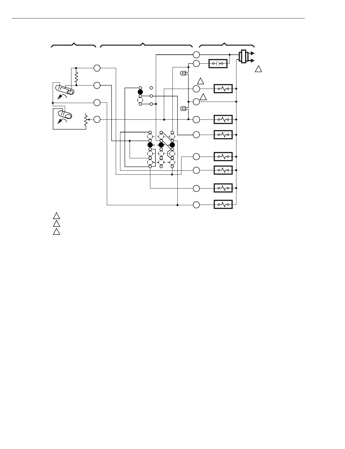
T874 MULTISTAGE THERMOSTATS AND Q674 SUBBASES
60-2485—8204
Fig. 218. Schematic and hookup of T874R with Q674L. Used in heat pump applications.
L1
(HOT)
L2
1
X
L
W2
EM. HT.
LED (RED)
AUX. HT.
LED (GRN) AUX. HT.
RELAY
FAN RELAY
"B" RELAY
G
COOL CHANGEOVER
VALVE
EM. HT. RELAY
COMPRESSOR
CONTACTOR
O
Y
E
B
SYSTEM
SWITCH
EM. HT.
HEAT
OFF
COOL
H1/C1
ANTICIPATOR
C1
H1
FALL
H2
W3
AUX. HT.
RELAY
H2
ANTICIPATOR
1
2
3
2
3
POWER SUPPLY. PROVIDE DISCONNECT MEANS AND OVERLOAD PROTECTION AS REQUIRED.
TERMINAL LABELED C/X ON SOME MODELS.
W3 TERMINAL AVAILABLE ON SOME MODELS ONLY.
M3683A
AUTO
ON
FAN
SWITCH
FALL
R
2
3
4
6
THERMOSTAT SUBBASE SYSTEM COMPONENTS
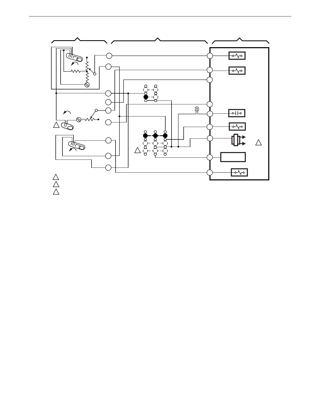
T874 MULTISTAGE THERMOSTATS AND Q674 SUBBASES
205 60-2485—8
Fig. 219. Schematic and hookup of T874C with Q674C. Used in standard applications.
M5901
L1
(HOT)
L2 1
FAN RELAY
SERVICE
LED (RED)
FAN SWITCH
OFF
AUTO
SYSTEM
SWITCH
AUTO
C1
FALL
H1
FALL 2
4
8
H1
ANTICIPATOR
1POWER SUPPLY. PROVIDE DISCONNECT MEANS AND OVERLOAD PROTECTION AS REQUIRED.
MOMENTARY POSITION. SPRING RETURN TO "ON" UPON SWITCH RELEASE.
H2 OFFSET 12oF FROM H1.
THERMOSTAT SUBBASE SYSTEM COMPONENTS
ON
COMPRESSOR CONTACTOR 1
H2
RISE
10
MONENTARY
CIRCUIT
H2
ANTICIPATOR
HEAT RELAY 1
HEAT RELAY 2
1
6
2
2
9
CONTROL MODULE
A
W2
W1
O
G
Y1
R
W3
Y2
5
7
3
3
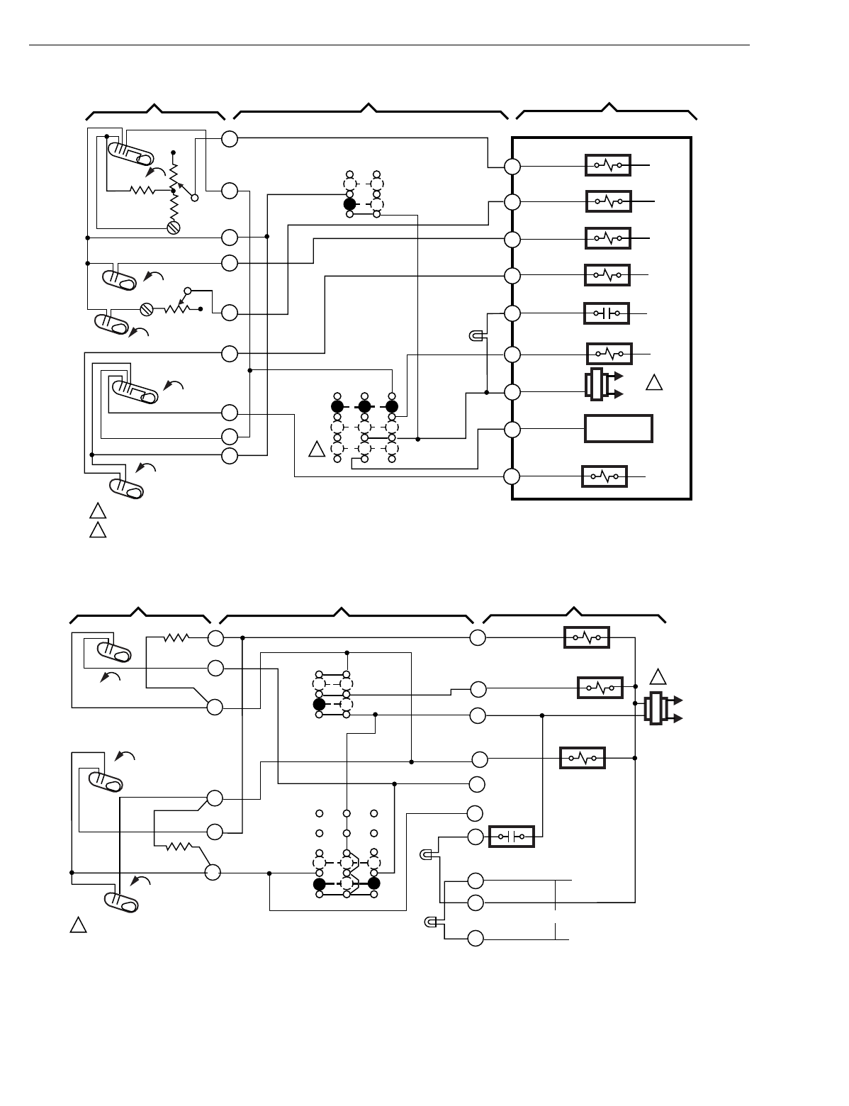
T874 MULTISTAGE THERMOSTATS AND Q674 SUBBASES
60-2485—8206
Fig. 220. Schematic and hookup of T874W with Q674C. Used in standard applications.
Fig. 221. Schematic and hookup of T874H with Q674C. Used in heat pump applications.
M5929
H1
FALL
L1
(HOT)
L2
1
THERMOSTAT SUBBASE SYSTEM COMPONENTS
1
4
6
8
9
10
FAN
SWITCH
SYSTEM
SWITCH
AUTO
OFF
ON
AUTO
SERVICE
LED (RED)
COMPRESSOR CONTACTOR #2
HEAT RELAY #2
FAN RELAY
COMPRESSOR CONTACTOR #1
HEAT RELAY #3
H1
ANTICIPATOR
H2
ANTICIPATOR
C1
C2 RISE
RISE
FALL
POWER SUPPLY. PROVIDE DISCONNECT MEANS AND OVERLOAD PROTECTION AS REQUIRED.
MOMENTARY POSITION. SPRING RETURN TO "ON" UPON SWITCH RELEASE.
1
CONTROL MODULE
H2
W3
Y1
G
R
W2
Y2
O
2
HEAT RELAY #1
W1
A
MOMENTARY
CIRCUIT
7
2
2
5
FALL
H3 SYSTEM MONITOR
M5902
L1
(HOT)
L2
1
Y2
X
R
COOL CHANGEOVER
VALVE
FAN SWITCH
ON
AUTO
SYSTEM
SWITCH
OFF
AUTO
H1
FALL
2
4
H1 ANTICIPATOR
1POWER SUPPLY. PROVIDE DISCONNECT MEANS
AND OVERLOAD PROTECTION AS REQUIRED.
THERMOSTAT SUBBASE SYSTEM COMPONENTS
C1 RISE
8
9
C1 ANTICIPATOR
3
10
CO
RISE
O
Y1
G
FAN RELAY
X2
C
X1
FILTER LED (RED)
SERVICE
LED (YELLOW)
COMPRESSOR
CONTACTOR
B
24 VAC
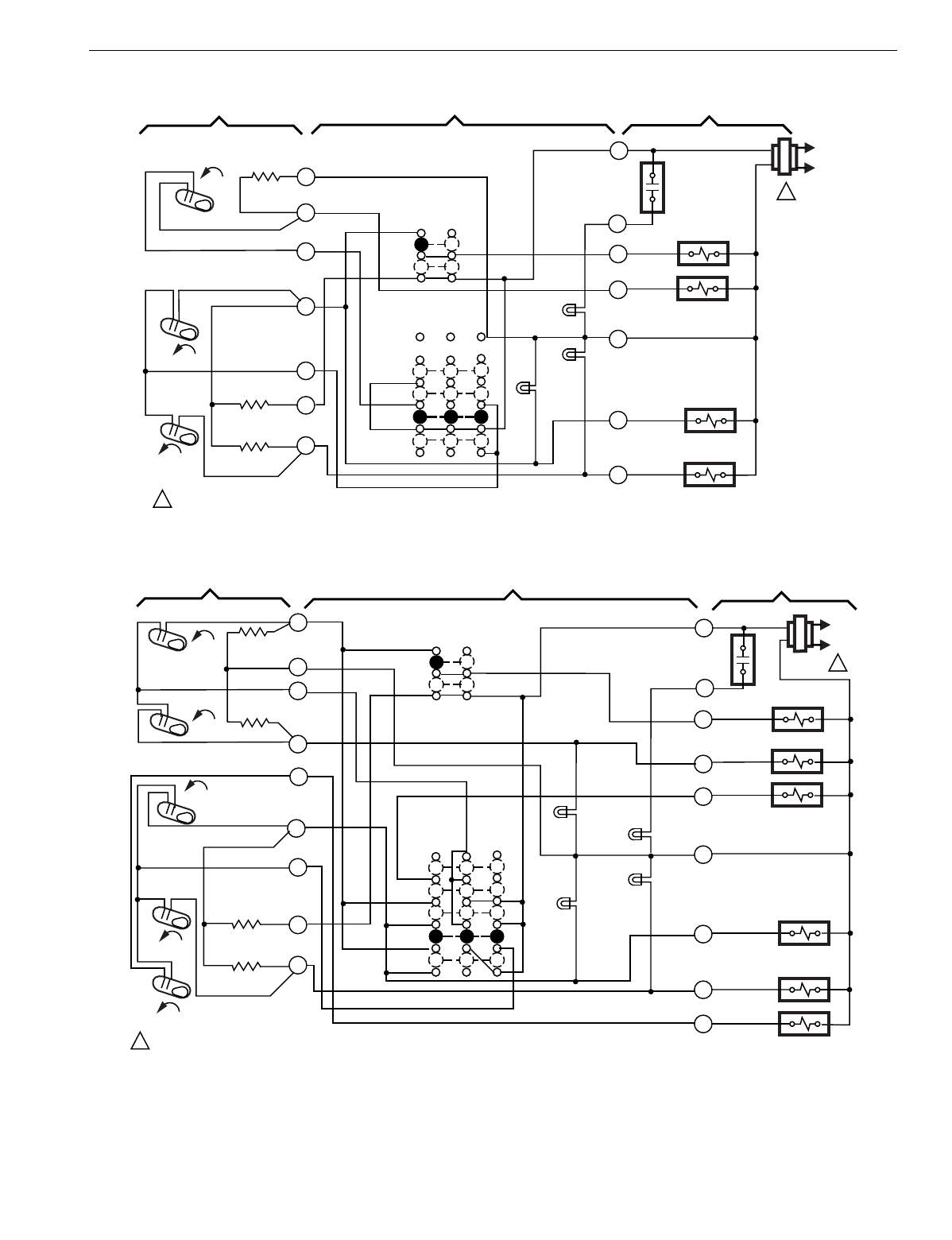
T874 MULTISTAGE THERMOSTATS AND Q674 SUBBASES
207 60-2485—8
Fig. 222. Schematic and hookup of T874B with Q674E. Used in standard applications.
Fig. 223. Schematic and hookup of T874S with Q674F. Used in heat pump applications.
M5920
L1
(HOT)
L2
1
C
W
R
FAN RELAY
COMPRESSOR
CONTACTOR 2
HEAT RELAY
MALFUNCTION
LED (RED)
LOW
SPEED
LED
(GREEN)
FAN SWITCH
ON
AUTO
SYSTEM
SWITCH
HEAT
AUTO
COOL
C1
RISE
H1
FALL 2
3
4
8
H1 ANTICIPATOR
1POWER SUPPLY. PROVIDE DISCONNECT MEANS AND OVERLOAD PROTECTION AS REQUIRED.
SUBBASE SYSTEM COMPONENTS
Y2
Y1
OFF
COMPRESSOR
CONTACTOR 1
C2
RISE
9
10
11
C2
ANTICIPATOR
C1
ANTICIPATOR
L
G
HIGH SPEED
LED (YELLOW)
SYSTEM
MONITOR
THERMOSTAT
M5923
L1
(HOT)
L2
1
C
E
R
FAN RELAY
COMPRESSOR
CONTACTOR 2
EM.HT. RELAY
MALFUNCTION
LED (RED)
LOW SPEED
LED (GREEN)
SYSTEM
SWITCH
HEAT
AUTO
COOL
C2
RISE
H1 FALL
2
3
4
8
H1
ANTICIPATOR
1POWER SUPPLY. PROVIDE DISCONNECT MEANS AND OVERLOAD PROTECTION AS REQUIRED.
THERMOSTAT SUBBASE SYSTEM COMPONENTS
Y2
Y1
OFF
COMPRESSOR
CONTACTOR 1
CO
RISE
9
10
11
C2
ANTICIPATOR
C1
ANTICIPATOR
L
G
HIGH SPEED
LED (YELLOW)
5
OCOOL
CHANGEOVER VALVE
AUX. HT. RELAY
W2
AUX. HT.
LED (RED)
7
RISE
C1
EM. HT.
FAN SWITCH
ON
AUTO
H2
FALL
H2 ANTICIPATOR
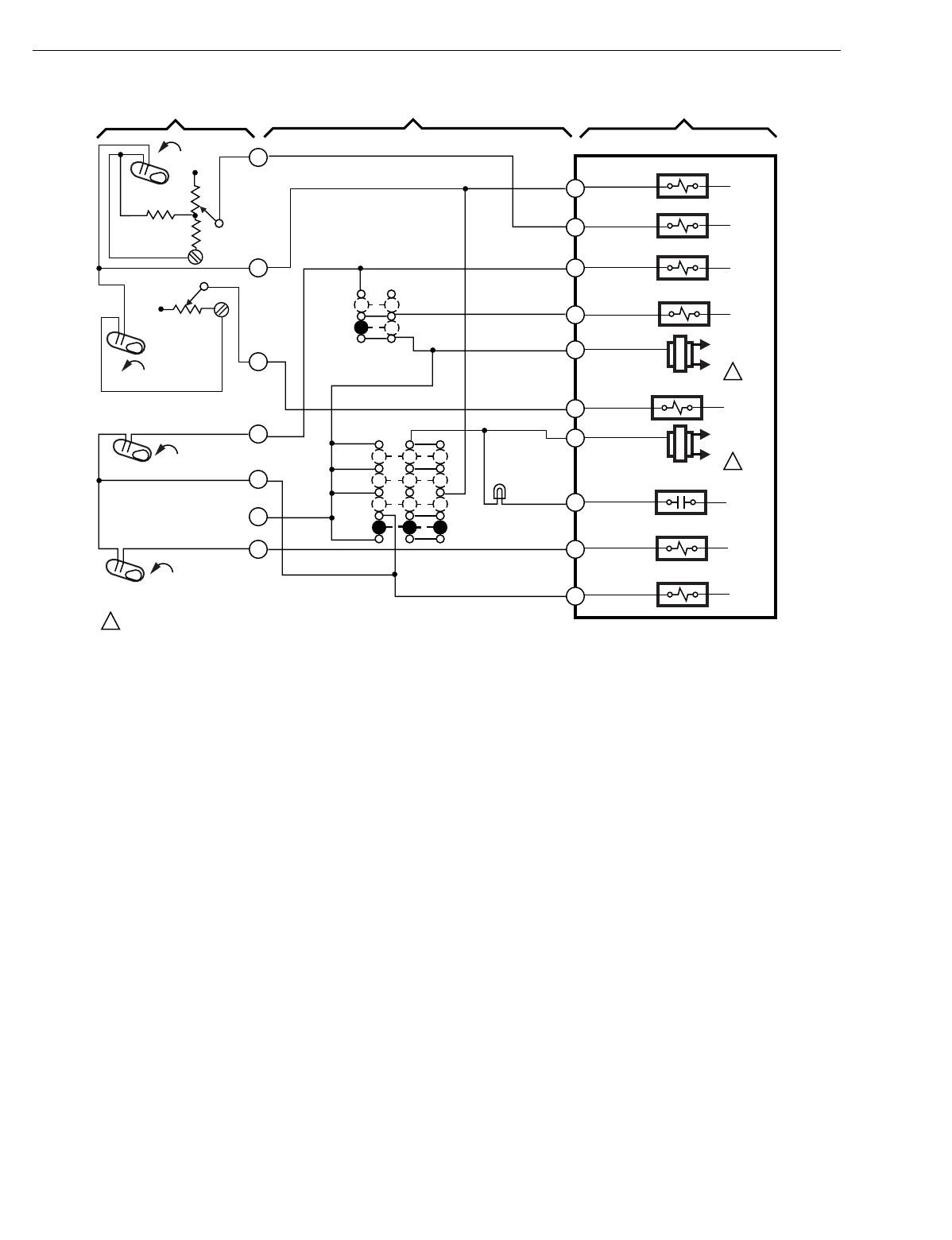
T874 MULTISTAGE THERMOSTATS AND Q674 SUBBASES
60-2485—8208
Fig. 224. Schematic and hookup of T874A,D with Q674E. Used in standard applications.
M5927
H1
FALL
L1
(HOT)
L2 1
L1
(HOT)
L2 1
THERMOSTAT SUBBASE SYSTEM COMPONENTS
1
4
6
8
9
10
11
FAN
SWITCH
SYSTEM
SWITCH
AUTO
ON
OFF
HEAT
AUTO
COOL
SERVICE
LED (RED)
COOL CHANGEOVER VALVE
COMPRESSOR CONTACTOR #2
HEAT RELAY #2
FAN RELAY
COMPRESSOR CONTACTOR #1
HEAT CHANGEOVER VALVE
HEAT RELAY #1
H1
ANTICIPATOR
H2
ANTICIPATOR
C1
C2 RISE
RISE
FALL
POWER SUPPLY. PROVIDE DISCONNECT MEANS AND OVERLOAD PROTECTION AS REQUIRED.
1
CONTROL MODULE
H2
B
W1
Y1
G
RC
W2
RH
A
Y2
O
SYSTEM MONITOR
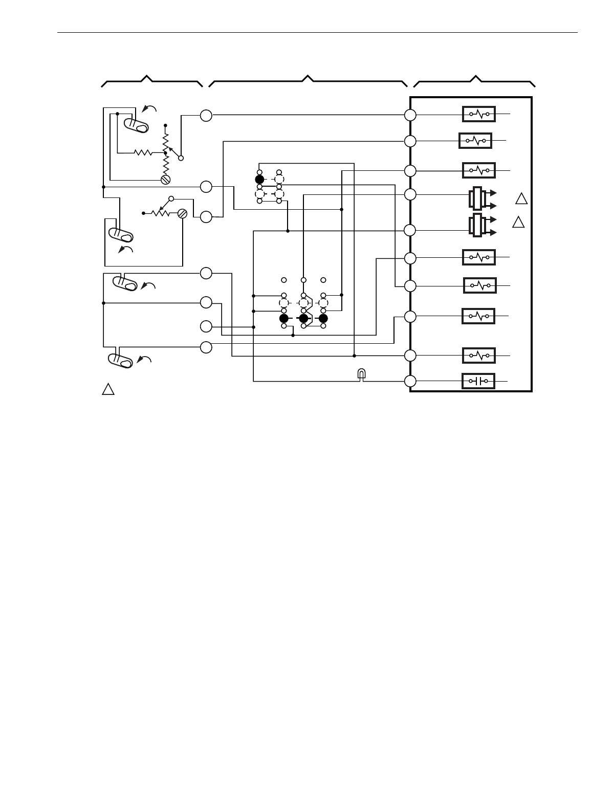
T874 MULTISTAGE THERMOSTATS AND Q674 SUBBASES
209 60-2485—8
Fig. 225. Schematic and hookup of T874D with Q674C. Used in standard applications.
M5928
H1
FALL
THERMOSTAT SUBBASE SYSTEM COMPONENTS
1
4
6
8
9
10
11
FAN
SWITCH
SYSTEM
SWITCH
AUTO
ON
OFF
AUTO
SERVICE
LED (RED)
COOL DAMPER
COMPRESSOR CONTACTOR #2
HEAT RELAY #2
FAN RELAY
COMPRESSOR CONTACTOR #1
HEAT DAMPER
HEAT RELAY #1
H1
ANTICIPATOR
H2
ANTICIPATOR
C1
C2 RISE
RISE
FALL
CONTROL MODULE
H2
B
W1
Y1
G
RC
W2
A
Y2
O
RH L1
(HOT)
L2 1
POWER SUPPLY. PROVIDE DISCONNECT MEANS AND OVERLOAD PROTECTION AS REQUIRED.
1
SYSTEM MONTIOR
L1
(HOT)
L2 1
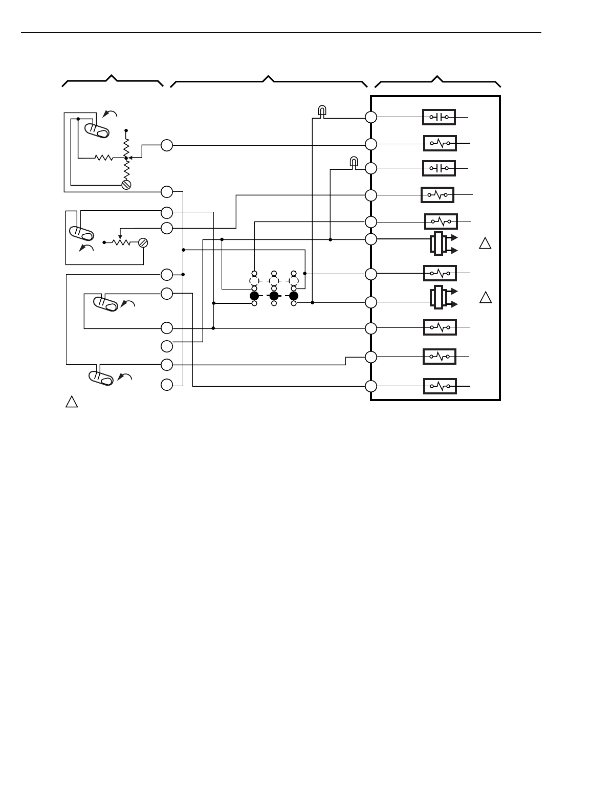
T874 MULTISTAGE THERMOSTATS AND Q674 SUBBASES
60-2485—8210
Fig. 226. Schematic and hookup of T874G with Q674G. Used in standard applications.
M5930
H1
FALL
L1
(HOT)
L2 1
L1
(HOT)
L2
1
THERMOSTAT SUBBASE SYSTEM COMPONENTS
1
4
6
8
9
10
11
SYSTEM
SWITCH
OFF
AUTO
SERVICE
LED (RED)
FAN RELAY O
COMPRESSOR CONTACTOR #2
HEAT RELAY #2
T RELAY
COMPRESSOR CONTACTOR #1
FAN RELAY B
HEAT RELAY #1
H1
ANTICIPATOR
H2
ANTICIPATOR
C1
C2
RISE
RISE
FALL
POWER SUPPLY. PROVIDE DISCONNECT MEANS AND OVERLOAD PROTECTION AS REQUIRED.
1
CONTROL MODULE
H2
B
W1
Y1
T
RC
W2
RH
A1
Y2
O
5
7
12
A2
SERVICE
LED (RED)
NO FAN
SWITCH
SYSTEM MONITOR
SYSTEM MONITOR
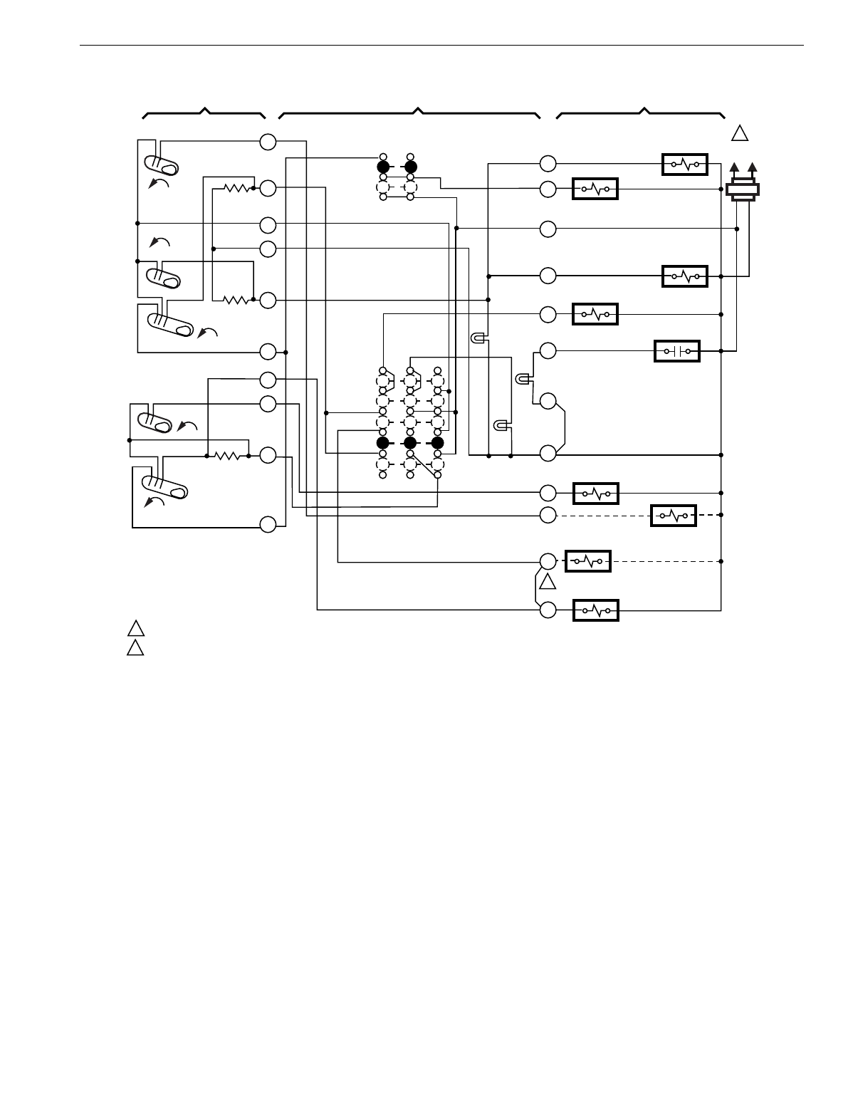
T874 MULTISTAGE THERMOSTATS AND Q674 SUBBASES
211 60-2485—8
Fig. 227. Schematic and hookup of T874G with Q674F. Used in heat pump applications.
CO
(HEAT)
FALL
H2
FALL
RISE
H1
FALL
L1
(HOT)
L2
1
2
1
2
RISE
C1
POWER SUPPLY. PROVIDE DISCONNECT MEANS AND OVERLOAD PROTECTION AS REQUIRED.
W1 - Y1 JUMPER IS Y TERMINAL; REMOVE JUMPER WHEN W1 RELAY IS USED.
THERMOSTAT SUBBASE SYSTEM COMPONENTS
M1230B
1
2
3
4
5
6
8
9
10
11
Y1
W1
B
O
X
X1
E
W2
R
G
W3
X2
W3 RELAY
FAN RELAY
AUX. HT.
RELAY
EM. HT.
RELAY
COMPRESSOR
FAULT
CHECK
LED (RED)
AUX.
HT. LED
(GREEN)
EM. HT.
LED (RED)
SYSTEM
SWITCH
OFF
EM. HT.
HEAT
AUTO
COOL COOL CHANGEOVER
RELAY
HEAT CHANGEOVER
RELAY
W1 RELAY
COMPRESSOR
CONTACTOR
C1
ANTICIPATOR
CO
(COOL)
H2 ANTICIPATOR
H1
ANTICIPATOR
FAN
SWITCH
AUTO
ON
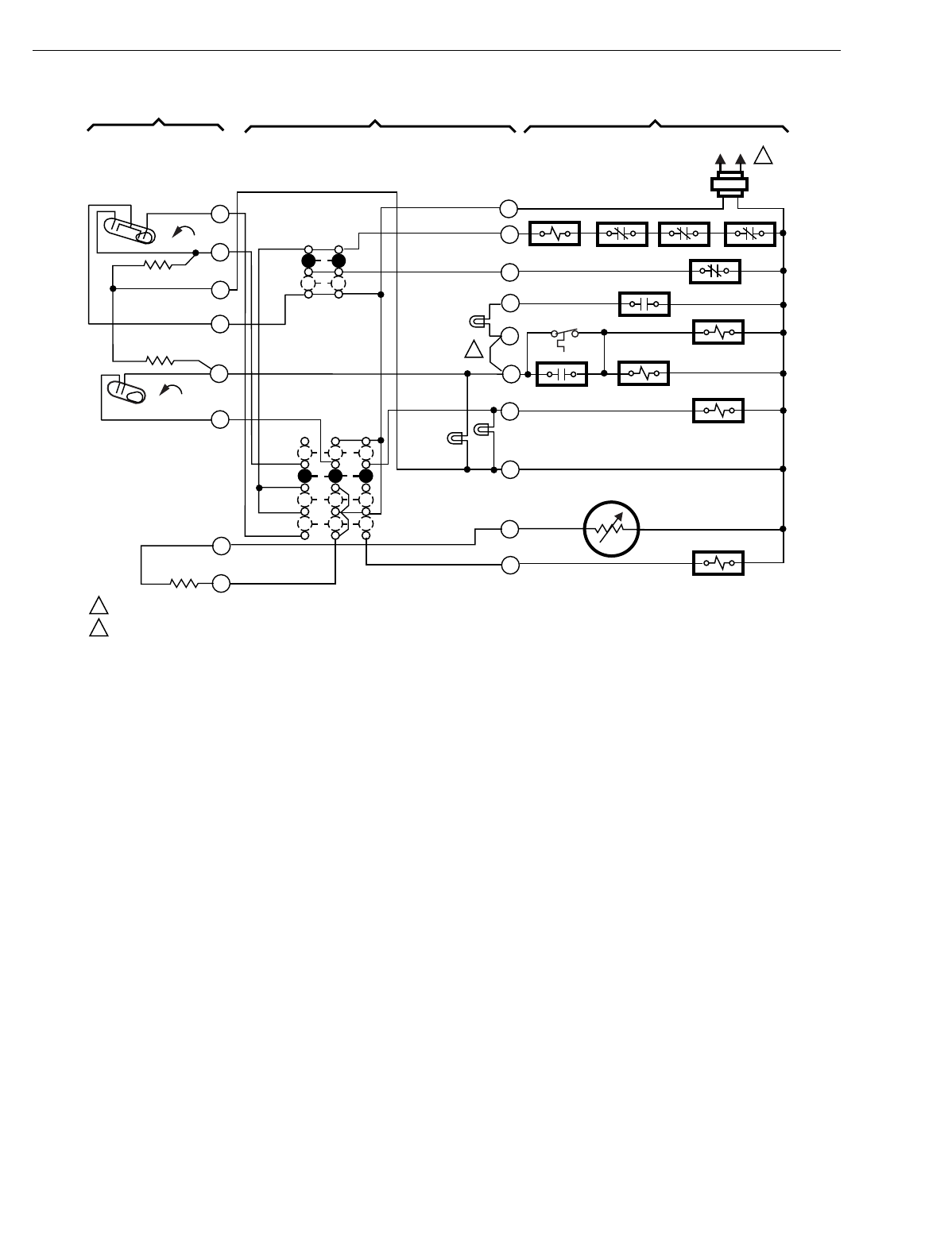
T874 MULTISTAGE THERMOSTATS AND Q674 SUBBASES
60-2485—8212
Fig. 228. Schematic and hookup of T874R with Q674L. Used in heat pump applications.
H1 FALL
C1
L1
(HOT)
L2
1
1
2
2
POWER SUPPLY. PROVIDE DISCONNECT MEANS AND OVERLOAD PROTECTION AS REQUIRED.
REMOVABLE JUMPER (INSTALLED).
THERMOSTAT SUBBASE SYSTEM COMPONENTS
H2 FALL
H1/C1 ANTICIPATOR
H2 ANTICIPATOR
RESET
EM. HT.
HEAT
OFF
COOL
AUX. HT.
LED
(GREEN)
EM. HT.
LED (YELLOW)
C815A OUTDOOR
THERMISTOR
COOL CHANGEOVER
VALVE
ELECTRIC
HEAT RELAY
ELECTRIC
HEAT RELAY
EM. HT.
O.D.S.
SERVICE
EM. HT. RELAY
FAN RELAY
COMP. RELAY O.L. IN. STAT. HI. PRO.
AUTO
ON
M3259
1
2
3
4
5
6
11
12
O
T
C
E
W1
L
G
Y1
R
SENSOR
LED (RED)
SYSTEM
SWITCH
FAN
SWITCH
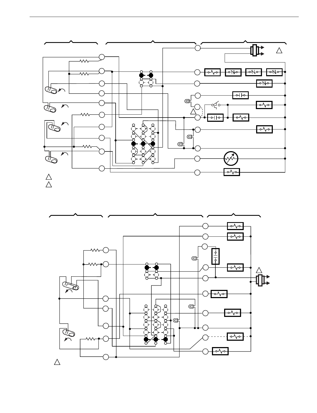
T874 MULTISTAGE THERMOSTATS AND Q674 SUBBASES
213 60-2485—8
Fig. 229. Schematic and hookup of T874G with Q674F. Used in heat pump applications.
Fig. 230. Schematic and hookup of T874R with Q674L. Used in heat pump applications.
H1 FALL
H2 FALL
CO
RISE
C1
RISE
L1
(HOT)
L2
1
2
1
2
POWER SUPPLY. PROVIDE DISCONNECT MEANS AND OVERLOAD PROTECTION AS REQUIRED.
REMOVABLE JUMPER (INSTALLED).
THERMOSTAT SUBBASE SYSTEM COMPONENTS
O.D.S.
H1 ANTICIPATOR
H2 ANTICIPATOR
C1 ANTICIPATOR
SYSTEM
SWITCH
FAN
SWITCH
AUTO
ON
EM. HT.
OFF
HEAT
AUTO
COOL
ELECTRIC
HT. RELAY
ELECTRIC
HT. RELAY
M3264
1
2
3
4
5
6
8
9
10
11
O
T
C
E
W1
L
G
Y1
R
EM. HT. RELAY
EM. HT.
EM. HT.
LED (YELLOW)
RESET
COMP. RELAY O.L. IN. STAT. HI. PRO
FAN RELAY
SERVICE
C815A OUTDOOR
THERMISTOR
COOL CHANGEOVER
VALVE
AUX. HT.
LED
(GREEN)
SERVICE
LED (RED)
H2
FALL
H1
FALL
C
L1
(HOT)
L2
1
1POWER SUPPLY. PROVIDE DISCONNECT MEANS AND
OVERLOAD PROTECTION AS REQUIRED.
THERMOSTAT SUBBASE SYSTEM COMPONENTS
M5068
H1
ANTICIPATOR
C ANTICIPATOR
H2
ANTICIPATOR
11
6
5
4
3
2
1
FAN
SWITCH
AUTO
ON
SYSTEM
SWITCH
EM .HT.
HEAT
OFF
COOL
AUX. HT.
LED
(GREEN)
EM. HT.
LED
(RED)
Y
B
X
E
W2
R
G
L
O
W3
W3 RELAY
COOL
CHANGEOVER VALVE
COMPRESSOR
MONITOR
FAN RELAY
AUX. HT. RELAY
EM. HT. RELAY
HEAT
CHANGEOVER VALVE
COMPRESSOR
RELAY
CHECK
LED (RED)
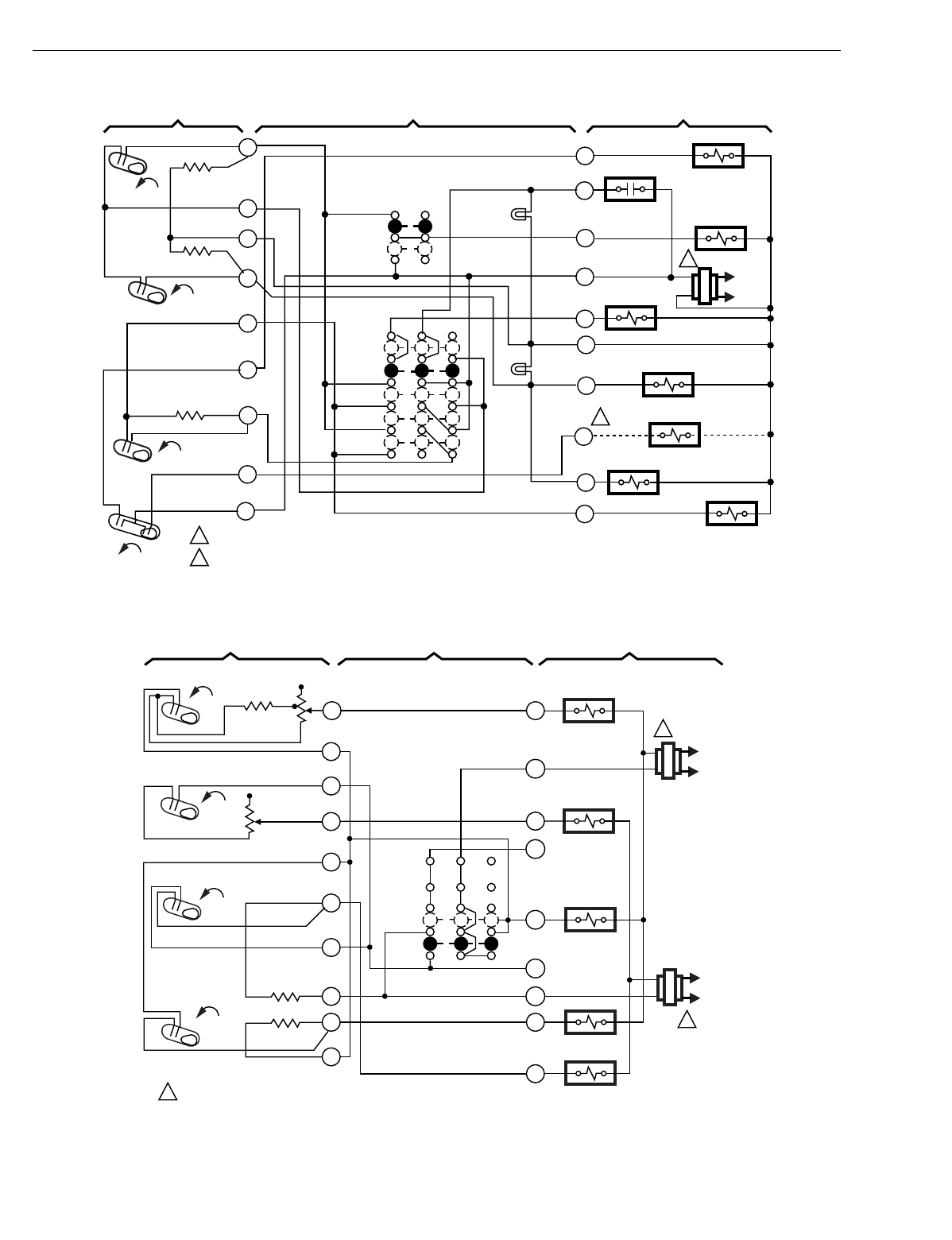
T874 MULTISTAGE THERMOSTATS AND Q674 SUBBASES
60-2485—8214
Fig. 231. Schematic and hookup of T874G with Q674F. Used in heat pump applications.
Fig. 232. Schematic and hookup of T874D with Q674G. Used in standard applications.
C1 RISE
H2 FALL
H1
FALL
H1
RISE
CO
L1
(HOT)
L2
1
2
1
2
POWER SUPPLY. PROVIDE DISCONNECT MEANS AND OVERLOAD PROTECTION AS REQUIRED.
ONLY TERMINAL B OR O TO BE USED. 0.8A MAX.
THERMOSTAT SUBBASE SYSTEM COMPONENTS
SYSTEM
SWITCH
FAN
SWITCH
AUTO
ON
OFF
EM. HT.
HEAT
AUTO
COOL
FAN RELAY
EM. HT. RELAY
AUX. HT. RELAY
COOL
CHANGEOVER
VALVE
HEAT CHANGEOVER
VALVE
COMPRESSOR
FAULT
H1
ANTICIPATOR
H2 ANTICIPATOR
C1
ANTICIPATOR
M5152
COMPRESSOR
RELAY
W3 RELAY
AUX. HT.
LED (GREEN)
O
L
EM. HT.
LED (RED)
G
R
E
X
W2
B
W3
Y
12
11
10
9
5
4
3
2
8
L1
(HOT)
L2
1
SYSTEM
SWITCH
OFF
H1
ANTICIPATOR
H1
FALL
1POWER SUPPLY. PROVIDE DISCONNECT MEANS
AND OVERLOAD PROTECTION AS REQUIRED. M3957
RH
C1
Y1
H2
RISE
W1
C1
ANTICIPATOR
C2
RISE
AUTO
1
4
6
8
9
10
COMPRESSOR
CONTACTOR 2
FALL
HEAT RELAY 1
RC
Y2
11
C2
ANTICIPATOR
W2
HEAT RELAY 2
COMPRESSOR
CONTACTOR 1
L1
(HOT)
L2
1
12
B
5
7
FAN RELAY
O
T
H2
ANTICIPATOR
THERMOSTAT SUBBASE SYSTEM COMPONENTS
NO FAN
SWITCH
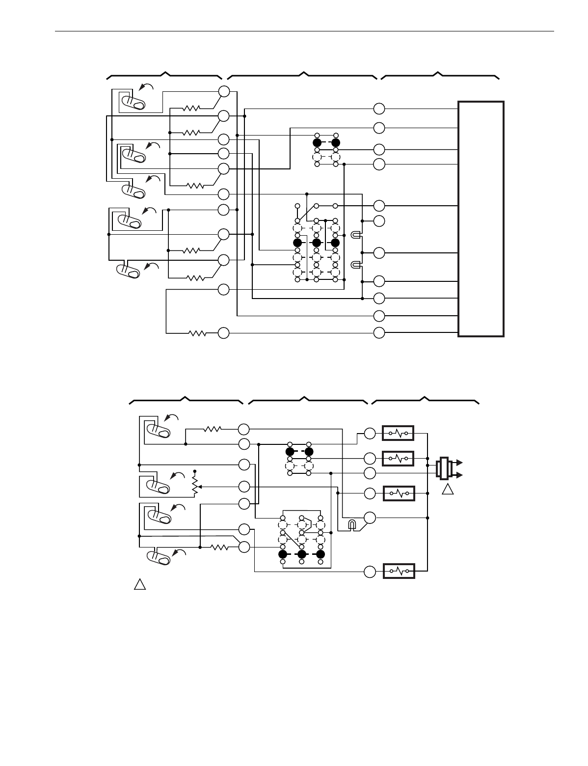
T874 MULTISTAGE THERMOSTATS AND Q674 SUBBASES
215 60-2485—8
Fig. 233. Schematic and hookup of T874W with Q674L. Used in heat pump applications.
Fig. 234. Schematic and hookup of T874G with Q674B. Used in heat pump applications.
FAN
SYSTEM
SWITCH
COOL
HEAT
H1
ANTICIPATOR
H1
FALL
M3952
AUTO
ON
FAN
SWITCH
R
G
L
Y
X
H3
E
W2
B
EM. HT.
LED (YELLOW)
1
2
3
5
4
6
SERVICE
LED (RED)
COMPRESSOR
LOW SPEED
FALL
AUX. HT.
O
Y1
COMPRESSOR
HIGH SPEED
EM. HT.
OFF
EM. HT.
W89
HEAT
PUMP
CONTROL
PANEL
COOL
CHANGEOVER
H2
ANTICIPATOR
H3
ANTICIPATOR
SERVICE LIGHT
EM. HT. LIGHT
T
OUTDOOR
RESET
8
9
11
10
12
FALL
C2
ANTICIPATOR
C1
ANTICIPATOR
RISE
H2
C1
C2
RESET
THERMOSTAT SUBBASE SYSTEM COMPONENTS
RISE
L2
1
OFF
H1
ANTICIPATOR
H1
FALL
1POWER SUPPLY. PROVIDE DISCONNECT MEANS AND OVERLOAD PROTECTION AS REQUIRED. M3961
CO
Y1
H2
RISE
W1
C1
ANTICIPATOR
C1
RISE
HEAT
1
4
6
8
9
10
FALL
AUX. HT. RELAY
COMPRESSOR
CONTACTOR
L1
(HOT)
R
FAN RELAY
O
AUTO
ON
FAN
SWITCH
AUX. HEAT
LED (RED)
C
G
H2
ANTICIPATOR
2
COOL
CHANGEOVER
VALVE
COOL
THERMOSTAT SUBBASE SYSTEM COMPONENTS
SYSTEM
SWITCH
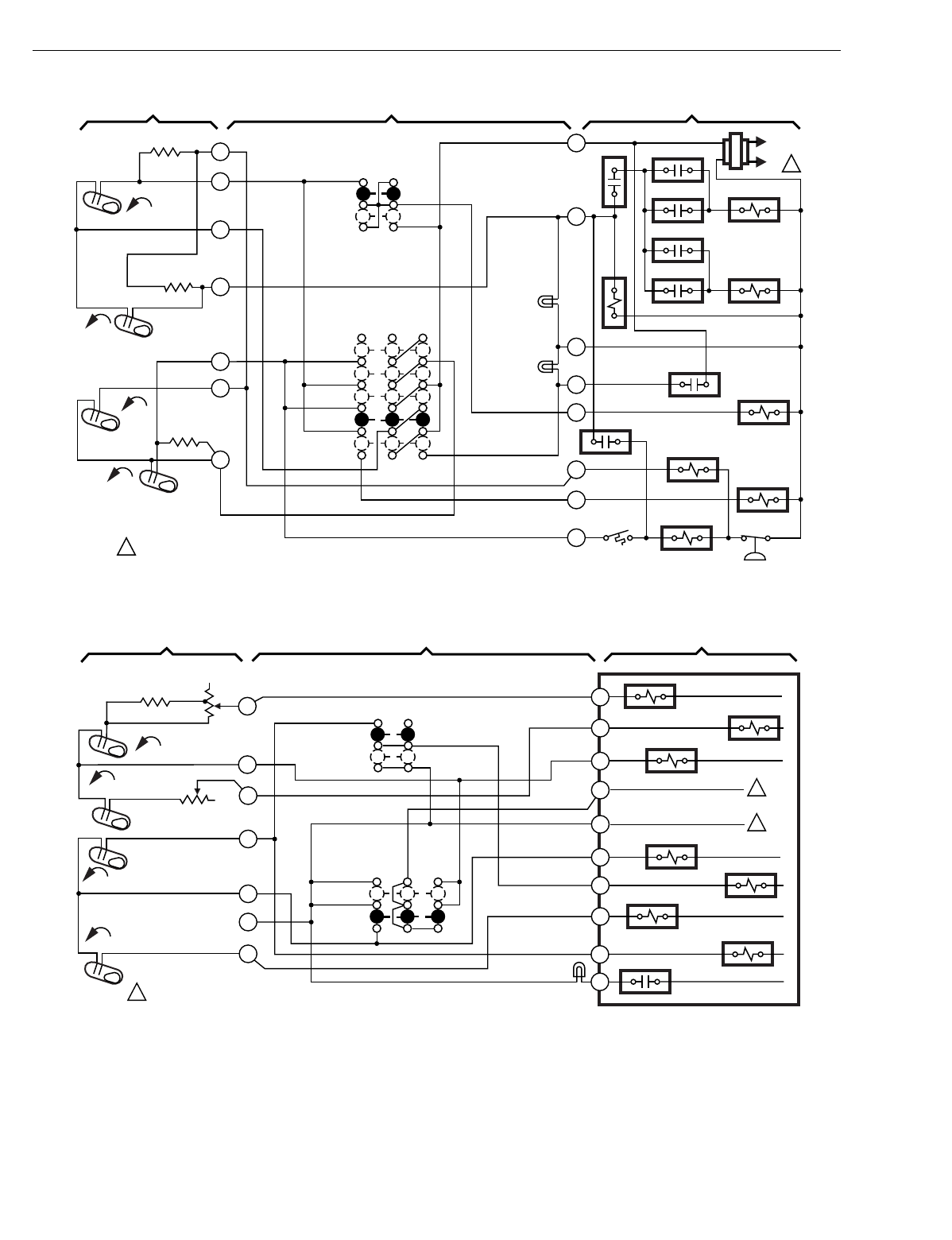
T874 MULTISTAGE THERMOSTATS AND Q674 SUBBASES
60-2485—8216
Fig. 235. Schematic and hookup of T874G and Q674F. Used in heat pump applications.
Fig. 236. Schematic and hookup of T874A-D with Q674C. Used in standard applications.
H2
FALL
L1
(HOT)
L2 1
R
W2
X
L
G
O
E
Y
RTD1 OTD1
EHR1
ODT2
EHR2
RTD2
RTD3
RTD1
SYSTEM
MONITOR
FAN
RELAY
RD
COOL
CHANGEOVER VALVE
EM. HT.
RELAY
LACO
COMPRESSOR
CONTACTOR CHP
2
3
4
5
8
9
10
H1 FALL
H1 ANTICIPATOR
H2
ANTICIPATOR
CHANGEOVER
RISE
C1
RISE
C1
ANTICIPATOR
OFF
COOL
AUTO
HEAT
EM. HT.
SYSTEM
SWITCH
AUTO
ON
FAN
SWITCH
AUX. HT.
LED (GRN)
EM. HT.
LED (RED)
POWER SUPPLY. PROVIDE DISCONNECT MEANS AND OVERLOAD
PROTECTION AS REQUIRED.
1M7064
THERMOSTAT SUBBASE SYSTEM COMPONENTS
Y1
RC
1
1
1
M7570
THERMOSTAT SUBBASE SYSTEM COMPONENTS
B
Y2
W2
RH
A
H1 ANTICIPATOR
H2 ANTICIPATOR
C1
RISE
H1 FALL
FALL
H2
C2
RISE
POWER SUPPLY. PROVIDE DISCONNECT MEANS AND OVERLOAD
PROTECTION AS REQUIRED.
O
1
6
9
10
11
4
8
AUTO
ON
FAN
SWITCH
SYSTEM
SWITCH
OFF
HEAT DAMPER
HEAT RELAY 1
COMPRESSOR
RELAY 1
HEAT RELAY 2
COMPRESSOR
RELAY 2
AUTO
SERVICE
LED (RED)
W1
G
COOL DAMPER
FAN RELAY
CONTROL MODULE
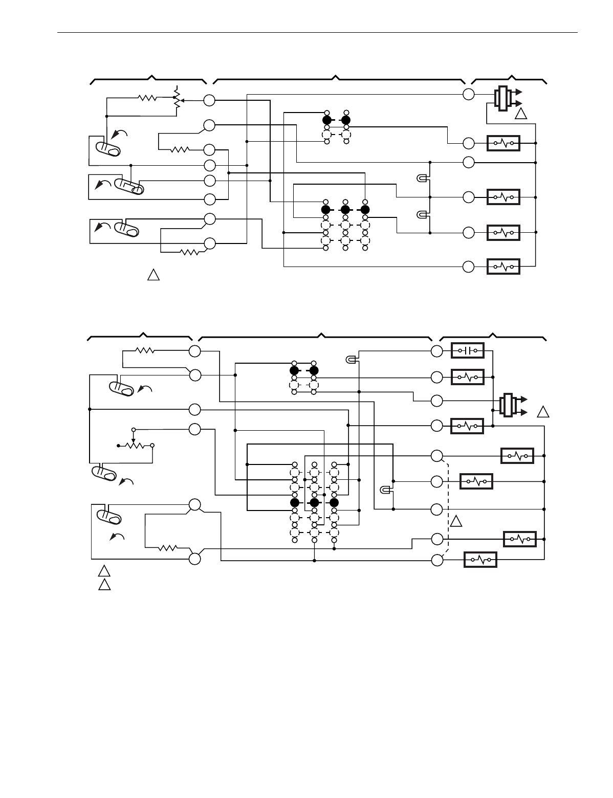
T874 MULTISTAGE THERMOSTATS AND Q674 SUBBASES
217 60-2485—8
Fig. 237. Schematic and hookup of T874C with Q674B. Used in standard applications.
Fig. 238. Schematic and hookup of T874C with Q674F. Used in heat pump applications.
H1
H2
FALL G
B
R
FAN RELAY
OFF
COOL
SYSTEM
SWITCH
H2 ANTICIPATOR
H1 ANTICIPATOR
C1 ANTICIPATOR
AUTO
ON
FAN SWITCH
1POWER SUPPLY. PROVIDE DISCONNECT MEANS AND OVERLOAD PROTECTION AS REQUIRED. M7716
THERMOSTAT SUBBASE SYSTEM COMPONENTS
3
4
6
8
10
FALL
RISE
C1
L1
(HOT)
L2
1
2
1
Y
COMPRESSOR
CONTACTOR
W1
W2
HEAT 1
HEAT 2
HEAT
5
LOW LED
(YELLOW)
HI LED
(GREEN)
H1
FALL
L1
(HOT)
L2 1
1
2
2
POWER SUPPLY. PROVIDE DISCONNECT MEANS AND OVERLOAD PROTECTION AS REQUIRED.
FACTORY INSTALLED JUMPER BETWEEN TERMINALS W1 AND Y1.
H1
ANTICIPATOR FAN SWITCH
AUTO
ON
SYSTEM
SWITCH
OFF
COOL
2
4
6
X
O
C
W1
W2
B
R
G
Y1
COOL
CHANGEOVER
VALVE
FAN RELAY
AUX. HT.
RELAY
HEAT PUMP
RELAY
M7719
C1
ANTICIPATOR
B RELAY
THERMOSTAT SUBBASE SYSTEM COMPONENTS
COMPRESSOR
CONTACTOR
AUX. HT.
LED (RED)
H2
RISE
C1
FALL
H2
ANTICIPATOR
1
8
10
2 STAGE HT.
HT. PUMP
AUX. HT.
CHECK
LED (RED)
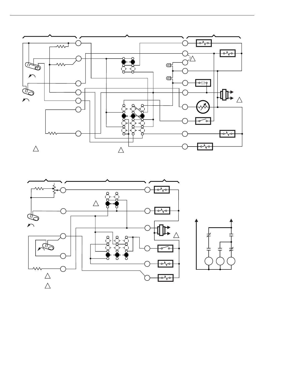
T874 MULTISTAGE THERMOSTATS AND Q674 SUBBASES
60-2485—8218
Fig. 239. Schematic and hookup of T874R with Q674L. Used in heat pump applications.
Fig. 240. Schematic and hookup of T874A with Q674W. Used in standard applications.
L1
(HOT)
L2 1
12
2
POWER SUPPLY. PROVIDE DISCONNECT MEANS
AND OVERLOAD PROTECTION AS REQUIRED.
FAN SWITCH
AUTO
ON
SYSTEM
SWITCH
HEAT
OFF
COOL
2
3
5
11
R
O
X2
T
G
B
W
Y
M7744
THERMOSTAT SUBBASE SYSTEM COMPONENTS
EM. HT.
H1
H2
FALL
FALL
C1
H1
ANTICIPATOR
RESET
U
F
FAN RELAY
AUX. HT.
RELAY
OUTDOOR
THERMOSTAT
COOL
CHANGEOVER
VALVE
COMPRESSOR
CONTACTOR
OUTDOOR
SENSOR
COMPRESSOR
MONITOR
1
4
6
AUX. HT.
LED (GREEN)
EM. HT.
LED (RED)
FIELD REMOVABLE JUMPER.
L1
(HOT)
L2 1
1
2
2
POWER SUPPLY. PROVIDE DISCONNECT MEANS
AND OVERLOAD PROTECTION AS REQUIRED.
FAN CONTINUOUS IN ON POSITION.
SYSTEM
OFF
ON
FAN
MED
MED
HI
HI
8
10
R
G2
G1
W1
B
Y1
M7745
THERMOSTAT SUBBASE SYSTEM COMPONENTS
LO
LO
H1
FALL
C1
RISE
C1
ANTICIPATOR
H1
ANTICIPATOR HEAT
RELAY
K1 RELAY
K2 RELAY
COMPRESSOR
CONTACTOR
1
4
9
B RELAY L2 L1
K1 K1
K2 K2 K2
3 SPEED FAN SCHEMATIC
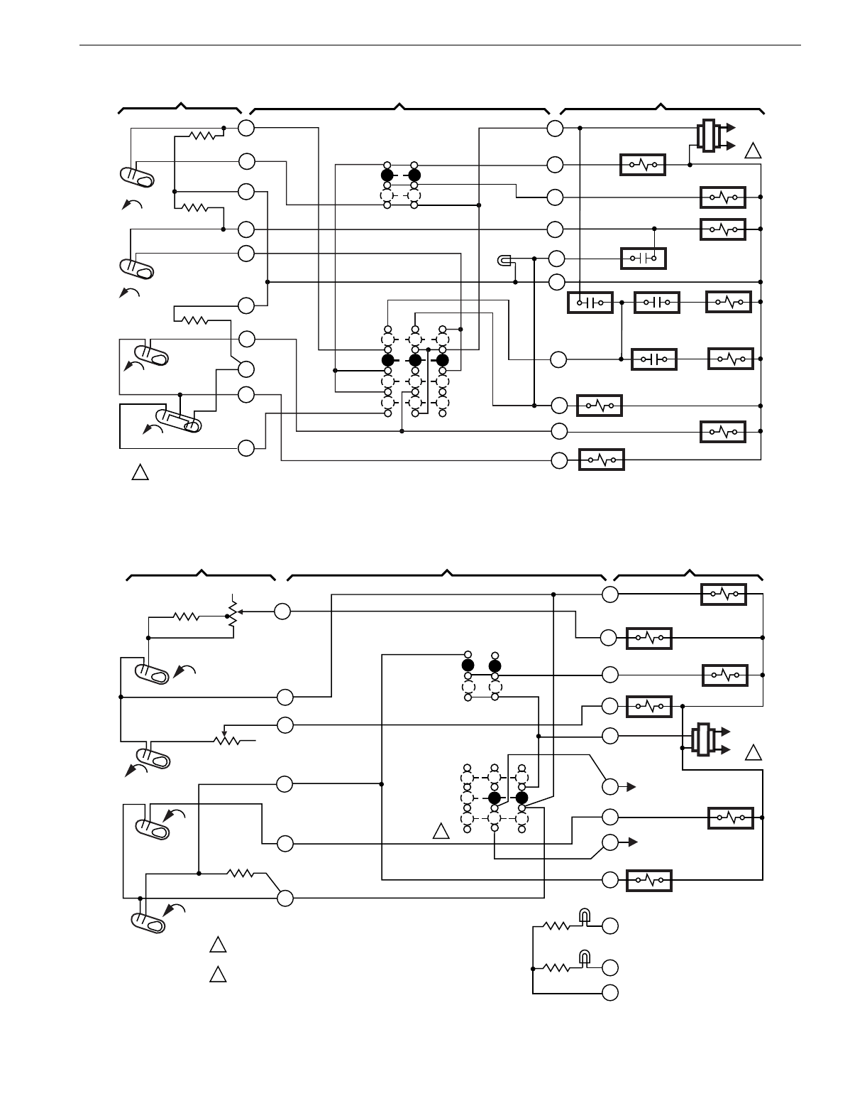
T874 MULTISTAGE THERMOSTATS AND Q674 SUBBASES
219 60-2485—8
Fig. 241. Schematic and hookup of T874J with Q674L. Used in heat pump applications.
Fig. 242. Schematic and hookup of T874G with Q674C. Used in standard applications.
RISE
L1
(HOT)
L2 1
1POWER SUPPLY. PROVIDE DISCONNECT MEANS AND OVERLOAD
PROTECTION AS REQUIRED.
FAN SWITCH
AUTO
ON
SYSTEM
SWITCH
HEAT
OFF
COOL
2
3
4
5
6
8
9
10
11
12
R
X
E
L
C
G
W2
Y
P
O
FAN RELAY
HEAT
CHANGEOVER
VALVE NO. 1
HEAT
CHANGEOVER
VALVE NO. 1
HEAT
CHANGEOVER
VALVE NO. 2
HEAT
CHANGEOVER
VALVE NO. 2
HEAT
CHANGEOVER
VALVE NO. 3
M7742
THERMOSTAT SUBBASE SYSTEM COMPONENTS
COOL CHANGEOVER
VALVE
SUPL. HT.
CO
H1
H2
FALL
FALL
CO
C1
RISE
COMPRESSOR
CONTACTOR
P RELAY
X RELAY
O.D.T.
SUPL. HEAT
LED (RED)
H1
ANTICIPATOR
H2
ANTICIPATOR
C1
ANTICIPATOR
L1
(HOT)
L2 1
H2 ANTICIPATOR
H1 ANTICIPATOR
C1 ANTICIPATOR
FALL
H1
R
W2
W1
G
B
1
2
2
POWER SUPPLY. PROVIDE DISCONNECT MEANS AND OVERLOAD
PROTECTION AS REQUIRED.
OVERRIDE IS MOMENTARY POSITION. SPRING RETURN TO (OFF)
UPON SWITCH RELEASE.
AUTO
ON
FAN
SWITCH
SYSTEM
SWITCH
AUTO
OVERRIDE
OFF
RISE
C1
C0
FALL
RISE
H2
Y
O
S1
S2
X
A
C
HEAT DAMPER
HEAT RELAY 1
FAN RELAY
HEAT RELAY 2
OVERRIDE
CIRCUIT
OVERRIDE
CIRCUIT
CHANGEOVER
VALVE
COMPRESSOR
RELAY
SERVICE
LED (RED)
ON LED (YEL)
M7212
1
4
6
8
9
10
THERMOSTAT SUBBASE SYSTEM COMPONENTS
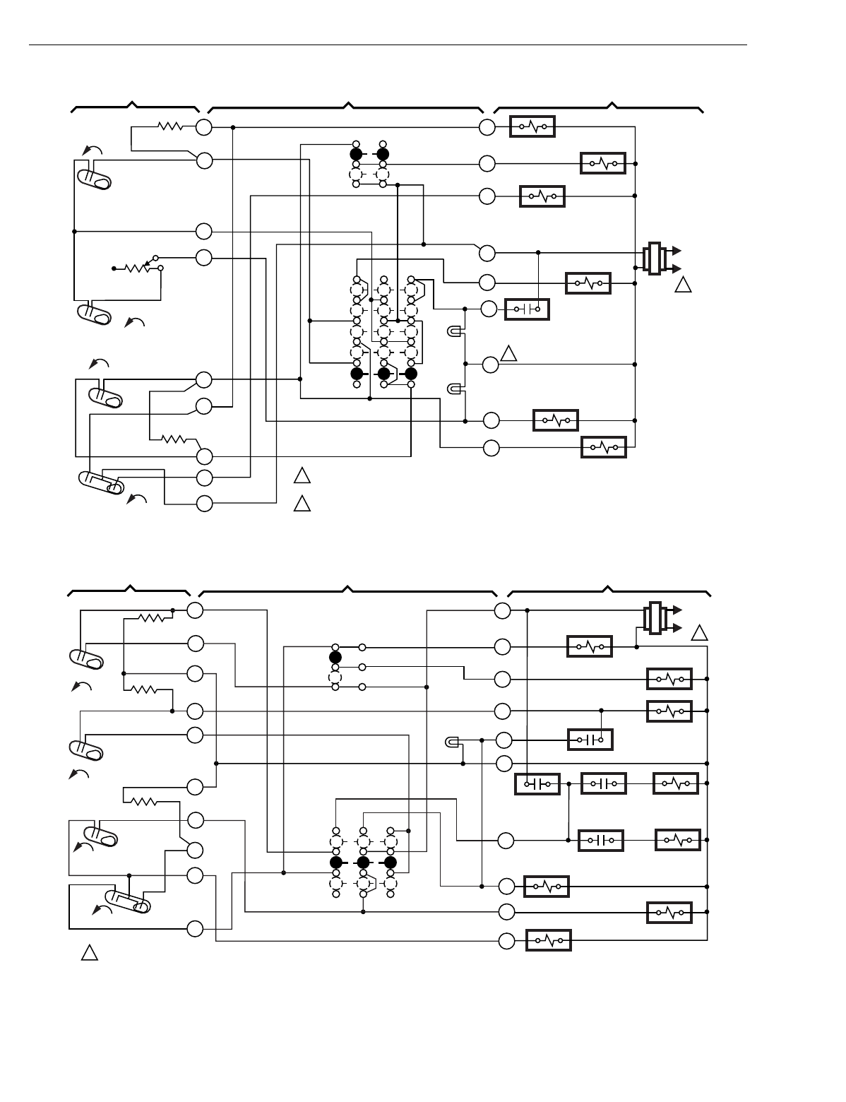
T874 MULTISTAGE THERMOSTATS AND Q674 SUBBASES
60-2485—8220
Fig. 243. Schematic and hookup of T874G with Q674F. Used in heat pump applications.
Fig. 244. Schematic and hookup of T874J with Q674J. Used in heat pump applications.
H1
FALL
RISE
CO
L1
(HOT)
L2
1
C1
RISE 1
2
2
POWER SUPPLY. PROVIDE DISCONNECT MEANS AND
OVERLOAD PROTECTION AS REQUIRED.
TERMINAL LABELED C/X ON SOME MODELS.
C1 ANTICIPATOR
H1 ANTICIPATOR FAN SWITCH
AUTO
ON
SYSTEM
SWITCH
AUTO
HEAT
OFF
COOL
1
2
4
6
8
9
10
O
W2
X
E
L
B
R
G
Y
AUX. HEAT RELAY
FAN RELAY
EM. HT. RELAY
B RELAY
M7715
THERMOSTAT SUBBASE SYSTEM COMPONENTS
11
12
COMPRESSOR
CONTACTOR
EM. HT.
EM. HT.
LED (RED)
AUX. HEAT
LED (GREEN)
COOL CHANGEOVER
VALVE
H2
FALL
H2
ANTICIPATOR
RISE
L1
(HOT)
L2 1
1POWER SUPPLY. PROVIDE DISCONNECT MEANS AND OVERLOAD
PROTECTION AS REQUIRED.
FAN SWITCH
AUTO
ON
SYSTEM
SWITCH
ON
OFF
2
3
4
5
6
8
9
10
11
12
R
X
E
L
C
G
W2
Y
P
O
FAN RELAY
HEAT
CHANGEOVER
VALVE NO. 1
HEAT
CHANGEOVER
VALVE NO. 1
HEAT
CHANGEOVER
VALVE NO. 2
HEAT
CHANGEOVER
VALVE NO. 2
HEAT
CHANGEOVER
VALVE NO. 3
M7743
THERMOSTAT SUBBASE SYSTEM COMPONENTS
COOL CHANGEOVER
VALVE
SUPL. HT.
CO
H1
H2
FALL
FALL
CO
C1
RISE
COMPRESSOR
CONTACTOR
P RELAY
X RELAY
O.D.T.
SUPL. HEAT
LED (RED)
H1
ANTICIPATOR
H2
ANTICIPATOR
C1
ANTICIPATOR
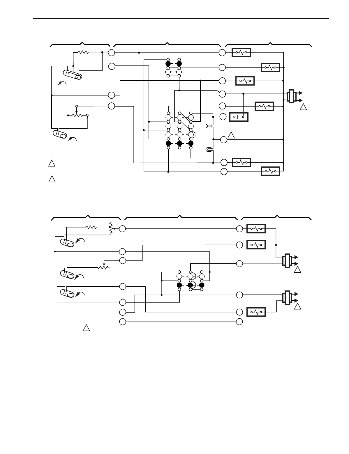
T874 MULTISTAGE THERMOSTATS AND Q674 SUBBASES
221 60-2485—8
Fig. 245. Schematic and hookup of T874R with Q674L. Used in heat pump applications.
Fig. 246. Schematic and hookup of T874C with Q674G. Used in standard applications.
H1
FALL
L1
(HOT)
L2
1
1
2
2
POWER SUPPLY. PROVIDE DISCONNECT
MEANS AND OVERLOAD PROTECTION
AS REQUIRED.
TERMINAL LABELED C/X ON SOME MODELS.
H1/C1
ANTICIPATOR FAN SWITCH
AUTO
ON
SYSTEM
SWITCH
HEAT
OFF
COOL
2
3
4
6
O
W2
X
E
L
B
R
G
Y
AUX. HT. RELAY
FAN RELAY
EM. HT. RELAY
B RELAY
M7718
THERMOSTAT SUBBASE SYSTEM COMPONENTS
COMPRESSOR
CONTACTOR
EM. HT.
EM. HT.
LED (RED)
AUX. HT.
LED (GREEN)
COOL CHANGEOVER
VALVE
H2
C1
FALL
H2
ANTICIPATOR
W2
W1
HEAT RELAY 1
OFF
AUTO
SYSTEM
SWITCH
1M7717
THERMOSTAT SUBBASE SYSTEM COMPONENTS
L1
(HOT)
L2
1
Y2
HEAT RELAY 2
RH
RC
Y1
COOL CHANGEOVER
VALVE
L1
(HOT)
L2
1
H1 ANTICIPATOR
H2 ANTICIPATOR
C1 RISE
H1 FALL
FALL
H2
POWER SUPPLY. PROVIDE DISCONNECT MEANS AND OVERLOAD
PROTECTION AS REQUIRED.
NO FAN
SWITCH
1
4
6
8
10
11
9
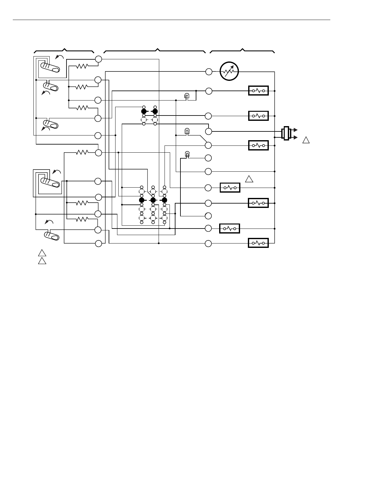
T874 MULTISTAGE THERMOSTATS AND Q674 SUBBASES
60-2485—8222
Fig. 247. Schematic and hookup of T874W with Q674L. Used in heat pump applications.
1
T
W3
G
R
E
X1
C
B
O
X2
Y1
Y2
C815A OUTDOOR
THERMISTOR
AUX. HT. RELAY
FAN RELAY
EM. HT. RELAY
CHANGEOVER
RELAY (HEAT)
CHANGEOVER
RELAY (COOL)
COMPRESSOR
CONTACTOR 1
COMPRESSOR
CONTACTOR 2
EM.HT.
AUTO
ON
FAN SWITCH
H1 ANTICIPATOR
H2 ANTICIPATOR
H3 ANTICIPATOR
RESET
FALL
FALL
FALL
H1
H3
H2
AUX. HEAT
LED (GREEN)
POWER SUPPLY. PROVIDE DISCONNECT MEANS AND OVERLOAD PROTECTION AS REQUIRED.
CONNECT CHANGEOVER RELAY TO 'O' TERMINAL FOR CHANGEOVER IN COOLING OR TO 'B' TERMINAL FOR CHANGEOVER IN HEATING. M6999
C1 ANTICIPATOR
RISE
RISE C2 ANTICIPATOR
C1
C2
EM. HEAT
LED (RED)
CHECK LED
(YELLOW)
HEAT
OFF
COOL
SYSTEM
SWITCH
2
2
THERMOSTAT SUBBASE SYSTEM COMPONENTS
1
2
3
4
5
6
8
9
10
11
12
L1
(HOT)
L2 1
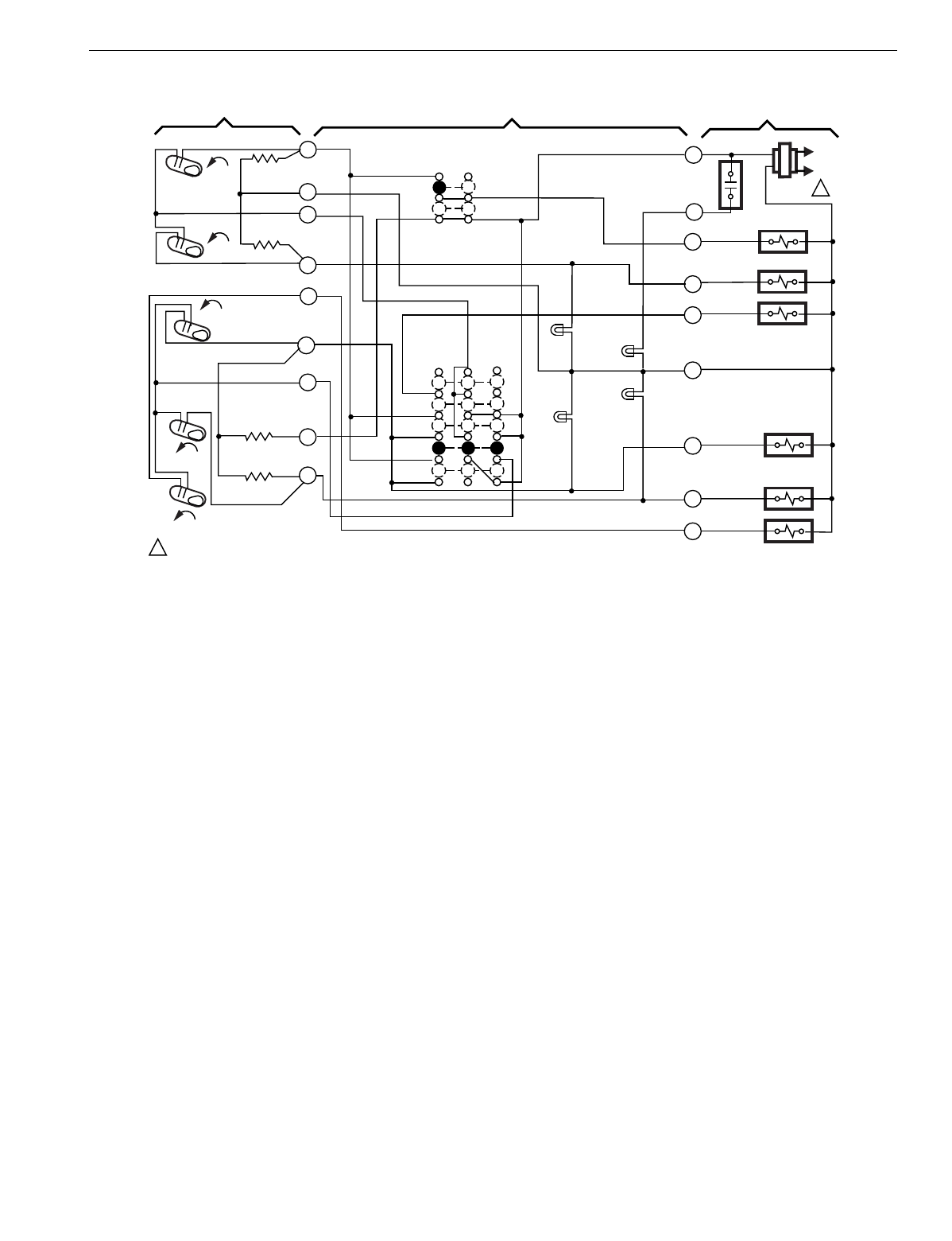
T874 MULTISTAGE THERMOSTATS AND Q674 SUBBASES
223 60-2485—8
Fig. 248. Schematic and hookup of T874Y with Q674F. Used in heat pump applications.
M5923
L1
(HOT)
L2
1
C
E
R
FAN RELAY
COMPRESSOR
CONTACTOR 2
EM.HT. RELAY
MALFUNCTION
LED (RED)
LOW SPEED
LED (GREEN)
SYSTEM
SWITCH
HEAT
AUTO
COOL
C2
RISE
H1 FALL
2
3
4
8
H1
ANTICIPATOR
1POWER SUPPLY. PROVIDE DISCONNECT MEANS AND OVERLOAD PROTECTION AS REQUIRED.
THERMOSTAT SUBBASE SYSTEM COMPONENTS
Y2
Y1
OFF
COMPRESSOR
CONTACTOR 1
CO
RISE
9
10
11
C2
ANTICIPATOR
C1
ANTICIPATOR
L
G
HIGH SPEED
LED (YELLOW)
5
OCOOL
CHANGEOVER VALVE
AUX. HT. RELAY
W2
AUX. HT.
LED (RED)
7
RISE
C1
EM. HT.
FAN SWITCH
ON
AUTO
H2
FALL
H2 ANTICIPATOR
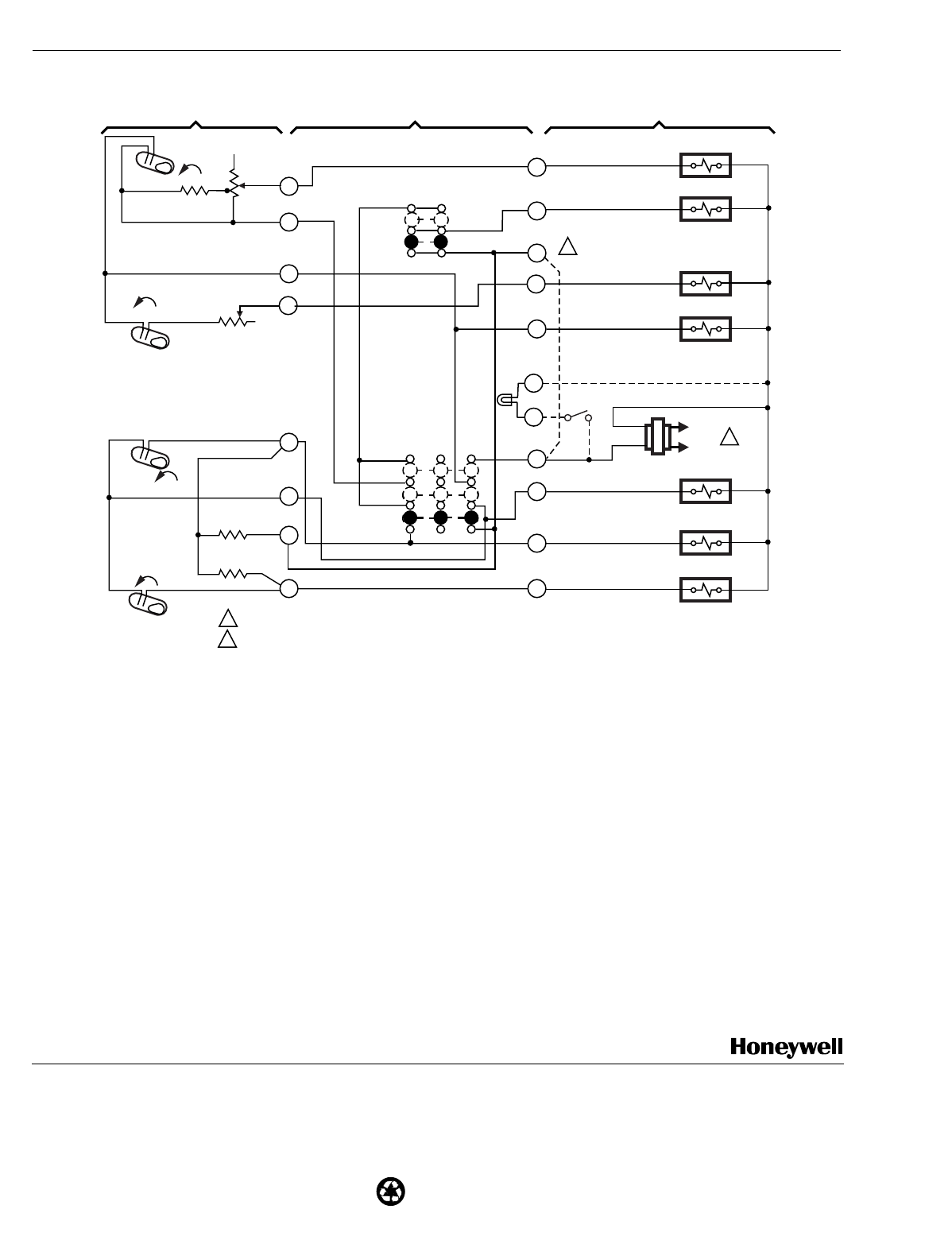
60-2485—8 J.H. Rev. 3-01 www.hone
y
well.com
Home and Building Control Home and Building Control
Honeywell Honeywell Limited-Honeywell Limitée
1985 Douglas Drive North 35 Dynamic Drive
Golden Valley, MN 55422 Scarborough, Ontario
M1V 4Z9
Printed in U.S.A. on recycled
paper containing at least 10%
post-consumer paper fibers.
T874 MULTISTAGE THERMOSTATS AND Q674 SUBBASES
Fig. 249. Schematic and hookup of T874C with Q674B. Used in heat pump applications.
C2
RISE
L1
(HOT)
L2 1
C1
RISE
H2
FALL
H1
FALL
M18622
H1 ANTICIPATOR
H2 ANTICIPATOR
C1 ANTICIPATOR
C2 ANTICIPATOR
POWER SUPPLY. PROVIDE DISCONNECT MEANS AND OVERLOAD PROTECTION AS REQUIRED.
FIELD WIRE JUMPER TO ALLOW SINGLE SYSTEM TRANSFORMER.
1
2
1
3
4
6
8
9
10
11 Y2
Y1
O
RH
B
W2
RC
G
W1
2
SYSTEM
SWITCH
HEAT
OFF
COOL
ON
AUTO
FAN
SWITCH
HEAT RELAY 1
FAN RELAY
HEAT RELAY 2
HEAT DAMPER
COOL DAMPER
COMPRESSOR CONTACTOR 1
COMPRESSOR CONTACTOR 2
THERMOSTAT SUBBASE SYSTEM COMPONENTS
SERVICE
LED (RED)
C
X
