Budderfly S0911011 BUDDERFLY RF MULTI-WAY SWITCH User Manual QCVS0911011 1
Budderfly LLC BUDDERFLY RF MULTI-WAY SWITCH QCVS0911011 1
User Manual
Part No S0911011
Description:
/ŶƐƚĂůůŝŶŐĂƵĚĚĞƌĨůLJĂĚĂƉƚĞƌƚƌĂŶƐĨŽƌŵƐLJŽƵƌďƵŝůĚŝŶŐ͛ƐĞdžŝƐƚŝŶŐǁŝƌŝŶŐŝŶƚŽƚŚĞ͞ƵĚĚĞƌĨůLJKƉĞŶEĞƚǁŽƌŬ͟ĂŶĚĂůůŽǁƐƚŚĞĂĚapter
to monitor energy consumption and communicate the data to a facility controller.
The Budderfly RF Multi-Way Switch presents a battery powered solution to replace installed light switches that lack the presence
of a neutral, for operation it will use the RF to communicate withthe installed the plug and play Budderfly RF outletthat uses the
power line communication and thus require no re-wiring. The RF Multi-Way Switch requires to be installed within a range of 8
meters of Budderfly RF outlet. The Budderfly RF Multi-Way Switch is designed with battery saving features to prolong the battery
life.
The Budderfly RF Multi-Way Switch is a component of the Budderfly system and designed to work with all other Budderfly devices.
It is a plug-and-play replacement for your existing light switch.
NOTE: For remote control applications using the Budderfly software, the Budderfly RF Multi-Way Switch must be installed within a distance of
30 Feet from a nearby Budderfly RF outlet.
This device is designed for use only with permanently installed fixtures.
WARNING ʹELECTRICAL SHOCK HAZARD
x The Budderfly RF Multi-Way Switch is intended for installation in
accordance with the National Electric Code and local regulations in the
United States.
x If you are not knowledgeable or comfortable with electrical circuitry, you
should have a qualified electrician to install the Budderfly Switch for you.

Installation:
The Budderfly RF Multi-Way Switch may be used in new installations or to replace an existing wall switch. It could be used either as
a 2-way switch, or as a 3-way switch. The wiring steps for both configurations are explained in the following diagrams:
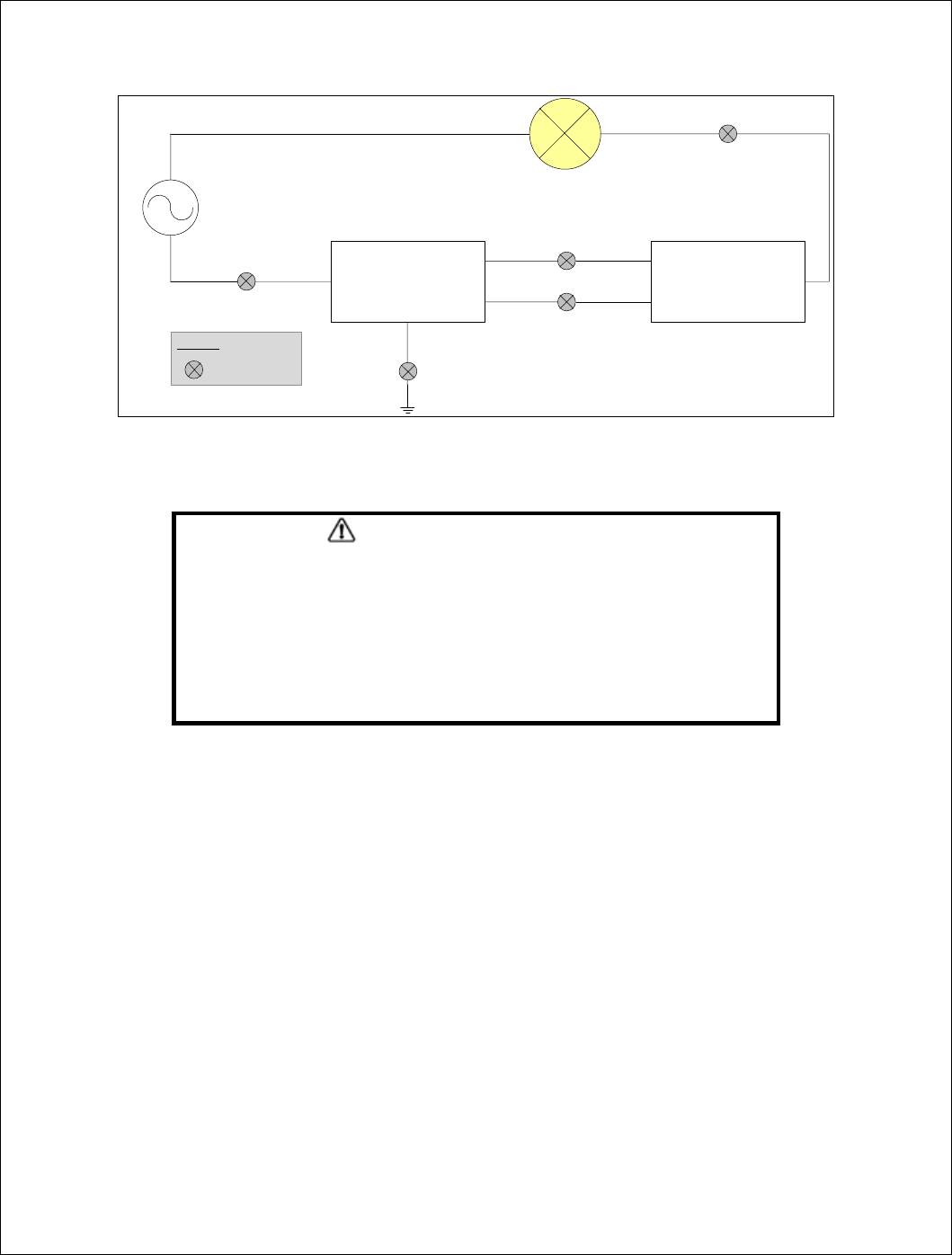
2-Way Configuration:
AC
BUDDERFLY
Multi-Way Switch
HOT
(Usually Black)
LIGHTING
LOAD
GROUND
(Green/Yellow)
HOT
(Black)
Traveler 2
(Blue)
Traveler 1
(Red)
NEUTRAL
(Usually White)
Legend:
Wiring Nuts
Not
Connected
Warning
RISK OF FIRE
RISK OF ELECTRICAL SHOCK
RISK OF BURNS
Exercise extreme caution when using Budderfly switching devices to control appliances.
To avoid the risk of Fire, Electrical Shock, Burns or other hazards we recommend the
following:
x Install the Budderfly switches indoor only.
x Never use the Budderfly switches to control medical and/or life support
equipment.
x Do not use the Budderfly switches to control electric heaters or any other
appliances which may present a hazardous condition due to unattended or
unintentional power on control.
x Never use the Budderfly switches with loads that exceed the maximum rating
specified.
WARNING ʹELECTRICAL SHOCK HAZARD
x Turn OFF the power to the branch circuit for the switch and lighting
fixture at the service panel.
x All wiring connections must be made with the POWER OFF to avoid
personal injury and/or damage to the switch.
3-Way Configuration:
AC
BUDDERFLY
Multi-Way Switch
HOT
(Usually Black)
LIGHTING
LOAD
GROUND
(Green/Yellow)
HOT
(Black)
Traveler 2
(Blue)
Traveler 1
(Red)
NEUTRAL
(Usually White)
Legend:
Wiring Nuts
Standard
Multi-Way Switch
LOAD
(Usually Black)
Traveler 2
(Usually Blue)
Traveler 1
(Usually Red)
1. Before installing the Budderfly RF Multi-Way Switch, make sure that a Budderfly RF plug will be installed within a distance
of 30 Feet.
2. At the circuit breaker or fuse panel, disconnect the power for all of the circuits in the switch junction box.
3. Double check that the power is OFF to the switch box before continuing by trying to turn on the controlled load.
4. Remove the wall plate from the switch you are replacing. Then, unscrew the switch itself and pull it out from the junction
box.
5. Disconnect the wires from the switch you are replacing.
6. Follow the wiring information provided below to connect the wires as follows:
x Connect the GROUND wire (usually Bare Copper or Green) to the Ground wire of Budderfly Switch (Yellow &
Green).
x 2-Way configuration:
o Connect the LOAD wire (usually Black) that goes to the light to the Traveler#1 (Red) wire of Budderfly Switch.
x 3-Way configuration:
o Connect the Traveler#1 (Usually Red) and Traveler#2 (Usually Blue) wires of the Standard Multi-Way Switch
to the Traveler#1 (Red) and Traveler#2 (Blue) wires of Budderfly Switch respectively.
o Connect the LOAD wire (usually Black) that goes to the light to the LOAD wire (usually Black) of the Standard
Multi-Way Switch.
x Connect the LINE wire (usually Black) that comes from the electrical service panel to the HOT wire of Budderfly
Switch (Black).
x Connect the NEUTRAL wire (usually White) to the Neutral wire of Budderfly Switch (White).
7. After you have connected all of the wires, ensure that all of the wire connectors are firmly attached and that there is no
exposed copper except for the GROUND wire.
8. Gently place Budderfly Switch into the junction box, orienting the unit with the LED bar on the left. Then, screw the switch
into place.
Wiring Information
x Important: Budderfly Switch is rated for and intended to only be used
with copper wire.
x Use 12 AWG or larger wires suitable for 80o.
x Remove 3/4" (1.9 cm) of insulation from each wire.
x Connect as follows: Twist strands of each end tightly together. Hold bare
ends of wires together and push firmly into wire Nut. Screw Nut
clockwise making sure that no bare conductor shows below the
connector.
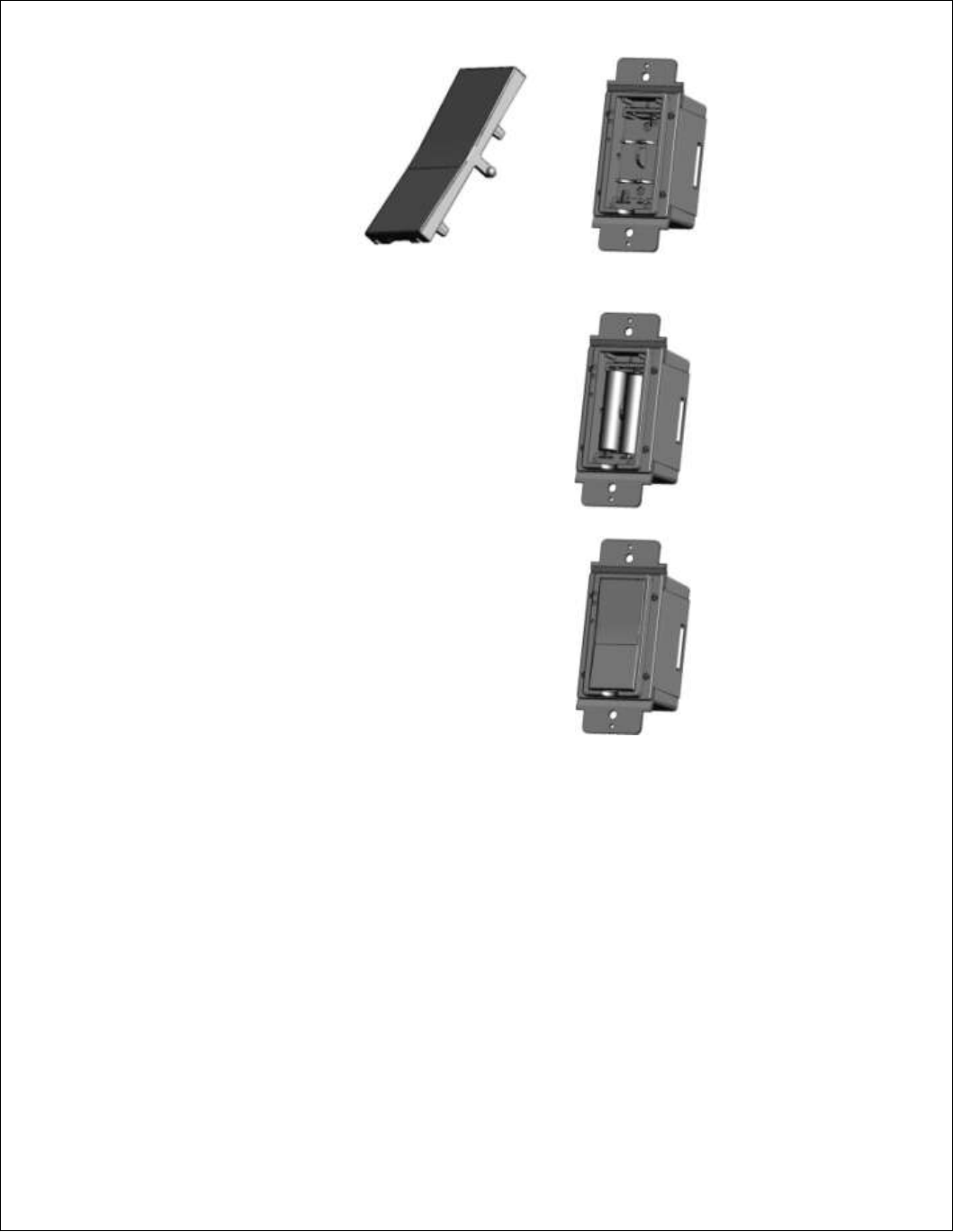
9. Place the batteries in the battery compartment as shown in the following three steps:
a. Remove the rocker
b. Insert the batteries as shown in the picture
c. Put the rocker back on
10. Reinstall the wall plate
11. Enable power to the switch from the circuit breaker or fuse panel
12. After the Enabling the power wait for 1 min, the Statues LED will turn ON for 10 seconds then is turned OFF indicating that
a connection with RF plug was established
13. Add the device address to the Budderfly web application.
͞WŽǁĞƌƵƚ-KĨĨ͟ŵŽĚĞ͗
- The Budderfly switches have the ability to completely disconnect the power from the load.
- Pressing ƚŚĞƚŽƉŽĨƚŚĞƌŽĐŬĞƌĨŽƌϭϱƐĞĐŽŶĚƐǁŝůůĂĐƚŝǀĂƚĞƚŚĞ͞WŽǁĞƌƵƚ-ŽĨĨ͟ĨĞĂƚƵƌĞ͖ƚŚĞůŽĂĚǁŝůůďĞƚƵƌŶĞĚŽĨĨ͘
- The Status LED will start blinking to indicate that the load is disconnected and the switch is in the Power Cut-off mode.
- tŚĞŶƚŚĞ͞WŽǁĞƌƵƚ-ŽĨĨ͟ mode is activated, the switch cannot be turned on through software and cannot be turned on
physically.
- Pressing the Bottom of the rocker again for 15 seconds will de-ĂĐƚŝǀĂƚĞƚŚĞ͞WŽǁĞƌƵƚ-ŽĨĨ͟ŵŽĚĞ͕ĂŶĚƚŚĞĚĞǀŝĐĞǁŝůůŐŽ
back to the normal state.
Features:
- Remote On/Off control
- Manual On/Off control
- No neutral required
On/Off Control:
- Remote Control:
o The Budderfly switches can be controlled remotely thru the Budderfly software.
o The Budderfly software will inform you that the action was successful. In case the action failed, please repeat
the procedure
- Manual Control: In addition to the Remote control, the Budderfly switches can be controlled manually.
o Tap the top of the rocker to turn ON the connected load.
o Tap the again top of the rocker to turn OFF the connected load.
Battery saving:
The Budderfly RF Multi-Way Switch is designed with battery saving features to minimize battery replacement. Battery life depends
on the sleep time, by default the devices are shipped with sleep time of 5seconds; this value can be changed as desired using
Budderfly software. Noting that the response time of the device for a command coming from the Budderfly software is less than or
equal the sleep time, the device will immediately respond with no delay when the rocker is pressed. If the device is installed
without installing an RF plug or if the plug was powered OFF, the device will scan for new connection in after 1 min, if no
connection is found it will scan again after 2 min then after 4 then 10 minutes and will repeat this after 3 hours, if an immediate
connection scan is required, it can be done by pressing the rocker or by resetting the device.
LED Indicators:
The Budderfly switches are equipped with 2 LED that indicates the different states of the device.
o Color: Green and Red
o State:
Activity Green LED Red LED
After Power ON or Reset Solid On for 3 sec Off
Power Cut-Off mode is activated Blinking Off
Searching for connection Solid On for up to 16 sec Off
Top rocker is pressed (Turn On) Blinks once Off
Bottom rocker is pressed (Turn Off) Off Blinks once
Breathing notification
Lights are On Blinks every sleep time
interval (5 sec by default) Off
Lights are Off Off
Blinks every sleep time
interval (5 sec by default)
WARNING ʹELECTRICAL SHOCK HAZARD
tŚĞŶƌĞƉůĂĐŝŶŐƚŚĞƵůďƐ͕ŵĂŬĞƐƵƌĞƚŽĞŶĂďůĞƚŚĞ͞WŽǁĞƌƵƚ-ŽĨĨ͟ŵŽĚĞ͘/ĨƚŚĞ
power LED does not start blinking, please consult a qualified electrician.

Reset:
If the device stops responding, it can be restarted by pushing the Reset Button. A non-metallic pin should be used to push the reset
button.
None of the stored parameters are affected.
WARNING ʹELECTRICAL SHOCK HAZARD
x Use only the plastic (non-metallic) pin provided with the device to press the reset
button.
x Never use a metallic pin to press the reset button.
Communication:
The Budderfly RF Multi-Way Switches use the radio frequency to communicate with the Budderfly RF plugswhich use the power
line to communicate wiƚŚƚŚĞ͞&ĂĐŝůŝƚLJŽŶƚƌŽůůĞƌ͘͟
The switches can reply to the following commands:
x Direct Turn On/Off command: the switch will turn the connected load On/Off.
x ^ĞƚƐůĞĞƉdŝŵĞĐŽŵŵĂŶĚ͗ƐĞƚ͛ƐƚŚĞĚĞǀŝĐĞƐůĞĞƉƚŝŵĞ͘
Specifications:
Power: 120V - 277V AC/ 60Hz
Maximum Loads:
x 120VAC, 60 Hertz:
o 1600W for Tungsten
o 1400W for Electronic ballast
o 800W for Standard ballast
x 277VAC, 60 Hertz:
o 3300W for Electronic ballast
o 1200W for Standard ballast.
x RF Operating Range:
o 8 meters
x Battery:
o 3V- 2 x 1.5V AAA Energizer Ultimate Lithium
x Frequency:
o 915Mhz
Neutral Line: NOT Required
Operating Temperature: 10 co to +40oC
Certification: UL certification is in progress
For indoor use only
Specifications subject to change without notice due to continuing product improvement.
Warranty:
Budderfly LLC warrants to the original consumer purchaser and not for the benefit of anyone else that this product at the time
of its sale by Budderfly is free of defects in material and workmanship under normal and proper use for a period of three (3)
yeaƌƐĨƌŽŵĚĂƚĞŽĨĚĞůŝǀĞƌLJƚŽLJŽƵ͘ƵĚĚĞƌĨůLJ͛ƐŽŶůLJŽďůŝŐĂƚŝŽŶŝƐƚŽĐŽƌƌĞĐƚƐƵĐŚĚĞĨĞĐƚƐďLJƌĞƉĂŝƌŽƌƌĞƉůĂĐĞŵĞŶƚ͕ĂƚŝƚƐŽƉƚion,
ŝĨǁŝƚŚŝŶƐƵĐŚƚŚƌĞĞLJĞĂƌƉĞƌŝŽĚƚŚĞƉƌŽĚƵĐƚŝƐƌĞƚƵƌŶĞĚƉƌĞƉĂŝĚǀŝĂƵĚĚĞƌĨůLJ͛ƐZĞƚƵƌŶĞĚDĂƚĞƌŝĂůƐƵƚŚŽƌŝnjĂƚŝŽŶ;ZDͿƉƌŽĐĞss
to Budderfly LLC, Att: Quality Assurance Department, 4 Corporate Drive, Suite 387, Shelton, CT 06484. In no case is product to
be returned without first obtaining an RMA.
This warranty excludes and there is disclaimed liability for labor for removal of this product or reinstallation. This warranty is
void if this product is installed improperly or in an improper environment, overloaded, misused, opened, abused, or altered in
any manner, or is not used under normal operating conditions or not in accordance with any labels or instructions. There are no
other or implied warranties of any kind, including merchantability and fitness for a particular purpose, but if any implied
warranty is required by the applicable jurisdiction, the duration of any such implied warranty is required by the applicable
jurisdiction, the duration of any such implied warranty, including merchantability and fitness for a particular purpose, is limited
to three years. Budderfly is not liable for incidental, indirect, special, or consequential damages, including without limitation,
damage to, or loss of use of, any equipment, lost sales or profits or delay or failure to perform this warranty obligation.
ƵĚĚĞƌĨůLJ͛ƐůŝĂďŝůŝƚLJŽŶĂŶLJĐůĂŝŵĨŽƌĚĂŵĂŐĞƐĂƌŝƐŝŶŐŽƵƚŽĨŝŶĐŽŶŶĞĐƚŝŽŶǁŝƚŚƚŚĞŵĂŶƵĨĂĐƚƵƌĞ͕ƐĂůĞƐ͕ŝŶƐƚĂůůĂƚŝŽŶĚĞůŝǀĞƌy, or
use of the product shall never exceed the purchase price of the product. The remedies provided herein are the exclusive
remedies under this warranty, whether based on contract, tort or otherwise.
WARNING
ŚĂŶŐĞƐ Žƌ ŵŽĚŝĨŝĐĂƚŝŽŶƐ ŶŽƚ ĞdžƉƌĞƐƐůLJ ĂƉƉƌŽǀĞĚ ďLJ ƚŚĞ ƉĂƌƚLJ ƌĞƐƉŽŶƐŝďůĞ ĨŽƌ ĐŽŵƉůŝĂŶĐĞ ĐŽƵůĚ ǀŽŝĚ ƚŚĞ ƵƐĞƌ͛Ɛ ĂƵƚŚŽƌŝƚLJ ƚŽ
operate this equipment
FCC Compliance Statement
This device complies with Part 15 of the FCC Rules. Operation is subject to the following two conditions:
(1) This device may not cause harmful interference and
(2) This device must accept any interference received, including interference that may cause undesired operation.
This equipment has been tested and found to comply with the limits for a class B digital device, pursuant to part 15 of the FCC
Rules. These limits are designed to provide reasonable protection against harmful interference in a residential installation. This
equipment generates, uses and can radiate radio frequency energy and if not installed and used in accordance with the
instructions, may cause harmful interference to radio communications. However, there is no guarantee that interference will not
occur in a particular installation. If this equipment does cause harmful interference to radio or television reception, which can be
determined by turning the equipment off and on, the user is encouraged to try to correct the interference by one or more of the
following measures:
x Reorient or relocate the receiving antenna.
x Increase the separation between the equipment and receiver.
x Connect the equipment into an outlet on a circuit different from that to which the receiver is connected.
x Consult the dealer or an experienced radio/TV technician for help.
The user is cautioned that changes and modifications made to the equipment without the approval of manufacturer could void the
user's authority to operate this equipment.
FCC ID: QCV S0911011
Made in China