Budderfly S1111111 Budderfly Switch Dimmer User Manual
Budderfly LLC Budderfly Switch Dimmer
User Manual
SWITCH DIMMER
Part No S1111111
Description:
Installing a Budderfly adapter transforms your building’s existing wiring into the “Budderfly Open Network” and allows
the adapter to monitor energy consumption and communicate the data to a facility controller.
The Budderfly Switch Dimmer is a dual band device. It communicates using both Powerline and wireless RF. Thus there is
no need for rewiring.
Using the Budderfly software, it is possible to visualize consumption data and manage each individual adapter.
As a component of the Budderfly system, the Budderfly Switch Dimmer is designed to work with all other Budderfly
adapters. It is a plug-and-play replacement for your existing switch dimmer, and it provides multiple dimming techniques.
Once installed, The Budderfly Switch Dimmer also acts as a repeater to extend the range of the network and increase its
efficiency.
Installation:
1. From the electrical panel board, turn off the circuit power feeding the switch
dimmer.
2. Remove the wall plate. Unscrew the old switch dimmer and pull it out from
the junction box.
3. Unscrew the wires from the terminal blocks on the Budderfly switch dimmer.
4. Prepare the wires by striping the insulation according to the strip gage
placed on the back of the switch dimmer package. The stripped copper
should be around 6.5 mm long.
5. Refer to the connection diagrams below in order to connect the switch
dimmer. The connection will change depending on the load.
6. After connecting all the wires, ensure that all the screws on the terminal
block are firmly tightened and that there is no exposed copper.
7. Place the switch dimmer in the junction box. Screw the switch dimmer into
place.
8. Reinstall the wall plate.
9. From the electrical panel board, turn on the circuit power feeding the switch
dimmer.
10. Add the device address to the Budderfly software.
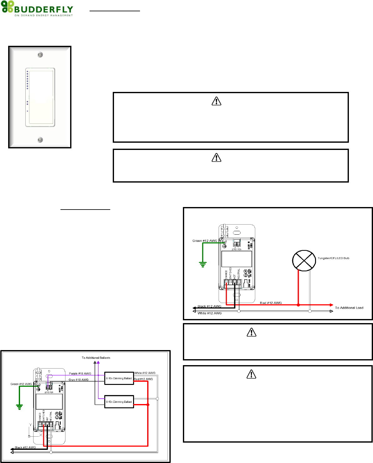
Connection Diagram A: Connection for 0-10v Dimming
Connection Diagram B : Connection for Phase Control Dimming
CAUTION
The Budderfly Switch Dimmer is intended for installation in accordance with the
National Electric Code and local regulations in the United States.
If you are not knowledgeable or comfortable with electrical circuitry, you should consult
a certified electrician for the installation
CAUTION
The Switch Dimmer is designed for indoor use only
Use only copper or copper-clad wires with this device
CAUTION
To Reduce the Risk of Overheating And Possible Damage To Other
Equipment, Do Not Install To Control A Receptacle, A Motor-Operated
Appliance, A Fluorescent Lighting Fixture, Or A Transformer-Supplied
Appliance.
Do Not use the Budderfly Switch Dimmer where excessive moisture
is present or near Water related Applications
Do Not use the Budderfly Switch Dimmer with loads that exceed
the maximum rating specified.
CAUTION
If you are not sure about any of the steps above, please consult a certified
electrician for the installation
Features:
- Eight dimming levels indicated with LED lights
- Supports multiple dimming techniques.
- Ability to resume from previous dimming level
- Ability to create a group of devices
- Ability to monitor power consumption
Remote Control:
o All the functions of the switch dimmer can be controlled remotely
using the Budderfly Software
o The Budderfly Software will inform you if the action was successful
Device Grouping:
o Using the Budderfly software, it is possible to create a Group of Switch
Dimmers.
o Devices that are member of the same group can be controlled with a
single click from the Budderlfy Applictaion
Power consumption:
o The Budderfly Switch Dimmer will measure the current, the voltage
and the power of the connected load and it will store the consumed
energy.
o The data can be accessed any time thru the Budderfly software. The
user can generate reports, monitor the consumption or check
expenses.
Reset:
If the device stops responding, it can be restarted by pushing the Reset Button.
A non-metallic pin should be used to push the reset button.
None of the stored parameters will be affected.
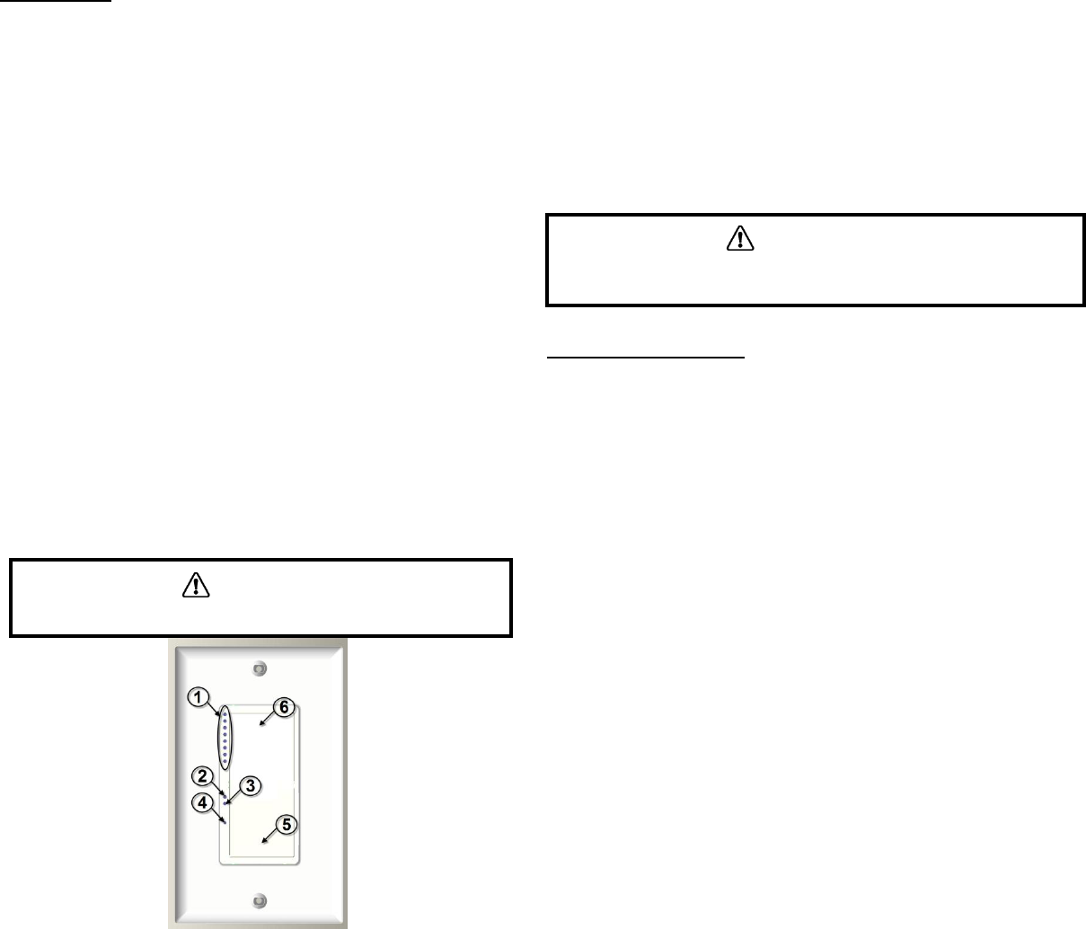
1- Dimming Level LEDs: These LEDs show the current dimming level from
1 to 8. Color : Green
2- Power LED: This led will turn on when the device is on. Color : Red
3- Group LED: This led will turn on when the device joins a group.
Color: Green.
4- Reset Button: If the device stops responding, it can be restarted using
this button. A non metallic pin must be used to push the reset button.
None of the stored parameters will be affected
5- Bottom Rocker: A single tap on this button will turn the device off
saving the current diming level. A Tap and Hold on this button will
cycle the light level down.
6- Top Rocker: A single tap on this button will turn the device on and
resume the previous dimming level. A Tap and Hold on this button will
cycle the light level up.
“Power Cut‐Off” mode:
‐ The Budderfly dimmers have the ability to completely disconnect the power
from the load.
‐ Pressing the top of the rocker for 15 seconds will activate the “Power Cut‐off”
feature; the load will be turned off.
‐ The Power LED will start blinking to indicate that the load is disconnected and
the dimmer is in the Power Cut‐off mode.
‐ When the “Power Cut‐off” mode is activated, the dimmer cannot be turned
on through software and cannot be turned on physically.
‐ Pressing the bottom of the rocker for 15 seconds will de‐activate the “Power
Cutoff” mode, and the device will go back to the normal state.
Communication:
The Budderfly Switch Dimmer is a dual band device. It communicates with the
“Facility Controller” using both Powerline and wireless RF. The following
commands are supported :
Direct Turn On/Off command: The load will be switched on or off
Direct Turn On level “X”: The load will be switched on to the dimming
level specified “X”.
Dim One Level Up : The load will be dimmed one level
Dim One Level Down: The load will be brightened one level
Join/Disjoin group “X”: The device will Join/Disjoin the group “X”.
Each dimmer can be member of several groups at the same time.
Group Turn On/Off: All Budderfly Switch Dimmers that are members
of the same group can be controlled remotely with one click.
Direct RTC synchronization: The Budderfly Switch Dimmer can receive
a command to synchronize its “Real Time Clock”
Get Actual Measurement: When the Budderfly Switch Dimmer
receives a “Get Measurement” command, it will send back to the
facility controller a string of data that contains:
- The Current in Amps “A”.
- The Power in Watt “W”.
- A Timestamp.
Get Stored Measurement: The Budderfly Dimmer Switch will send
back to the Facility Controller the stored electrical measurements.
Direct Reset Commands: The Budderfly Dimmer Switch can receive 3
types of reset commands:
- Hard Reset: This command will restart the device without
affecting any stored parameter.
- Data Reset: This command will erase all the measurement and
RTC data stored in the non-volatile memory.
- Group Reset: This command will remove the device from all
joined groups.
Group Reset Commands: The above reset commands can be directed
to a group of devices instead of just one device.
CAUTION
Never use a metallic pin to press the reset button.
CAUTION
When replacing the Bulbs, make sure to enable the “Power Cut‐off” mode. If
the power LED does not start blinking, please consult a qualified electrician.

Electrical Specs:
The Budderfly Switch Dimmer can handle multiple load types. Below is a
summary of these loads:
Voltage: 120/277 VAC - 60Hz
Maximum Switching Loads:
Tungsten
@120V 950W
@277V 2200W
Electronic Ballast
@120V 950W
@277V 2200W
Standard Ballast
@120V 950W
@277V 2200W
Maximum Phase Control Loads:
Tungsten
@120V 950W
@277V 2200W
Maximum 0-10v Dimming : 30mA
Operating Temperature : 10oC to +40oC
Certification : ETL & FCC in progress
For indoor use only
Derating Chart:
When combining multiple Dimmers in a gang box, the device must be derated.
Check the below chart for details.
Warranty:
Budderfly LLC warrants to the original consumer purchaser and not for the
benefit of anyone else that this product at the time of its sale by Budderfly is
free of defects in material and workmanship under normal and proper use for a
period of three (3) years from date of delivery to you. Budderfly’s only
obligation is to correct such defects by repair or replacement, at its option, if
within such three year period the product is returned prepaid via Budderfly’s
Returned Materials Authorization (RMA) process to Budderfly LLC, Att: Quality
Assurance Department, 4 Corporate Drive, Suite 387, Shelton, CT 06484. In no
case is product to be returned without first obtaining an RMA.
This warranty excludes and there is disclaimed liability for labor for removal of
this product or reinstallation. This warranty is void if this product is installed
improperly or in an improper environment, overloaded, misused, opened,
abused, or altered in any manner, or is not used under normal operating
conditions or not in accordance with any labels or instructions. There are no
other or implied warranties of any kind, including merchantability and fitness
for a particular purpose, but if any implied warranty is required by the
applicable jurisdiction, the duration of any such implied warranty is required by
the applicable jurisdiction, the duration of any such implied warranty, including
merchantability and fitness for a particular purpose, is limited to three years.
Budderfly is not liable for incidental, indirect, special, or consequential
damages, including without limitation, damage to, or loss of use of, any
equipment, lost sales or profits or delay or failure to perform this warranty
obligation. Budderfly’s liability on any claim for damages arising out of in
connection with the manufacture, sales, installation delivery, or use of the
product shall never exceed the purchase price of the product. The remedies
provided herein are the exclusive remedies under this warranty, whether based
on contract, tort or otherwise.
Load Type
Voltage
No Sides
Removed
1 Side
Removed
2 Sides
Removed
Incandescent
120V
950 W
600 W
600 W
277V
2200 W
1350 W
1350 W
FCC NOTE:
This device complies with Part 15 of the FCC Rules.
Operation is subject to the following two conditions: (1) this device
may not cause harmful interference, and (2) this device must
accept any interference received, including interference that may
cause undesired operation.
THE MANUFACTURER IS NOT RESPONSIBLE FOR ANY
RADIO OR TV INTERFERENCE CAUSED BY UNAUTHORIZED
MODIFICATIONS OR CHANGE TO THIS EQUIPMENT. SUCH
MODIFICATIONS OR CHANGE COULD VOID THE USER’S
AUTHORITY TO OPERATE THE EQUIPMENT.