Building 36 Technologies B36T10RB Thermostat User Manual
Building 36 Technologies, LLC Thermostat
User Manual
Intelligent Thermostat
User Guide
2 | Intelligent Thermostat User Guide Intelligent Thermostat User Guide | 3
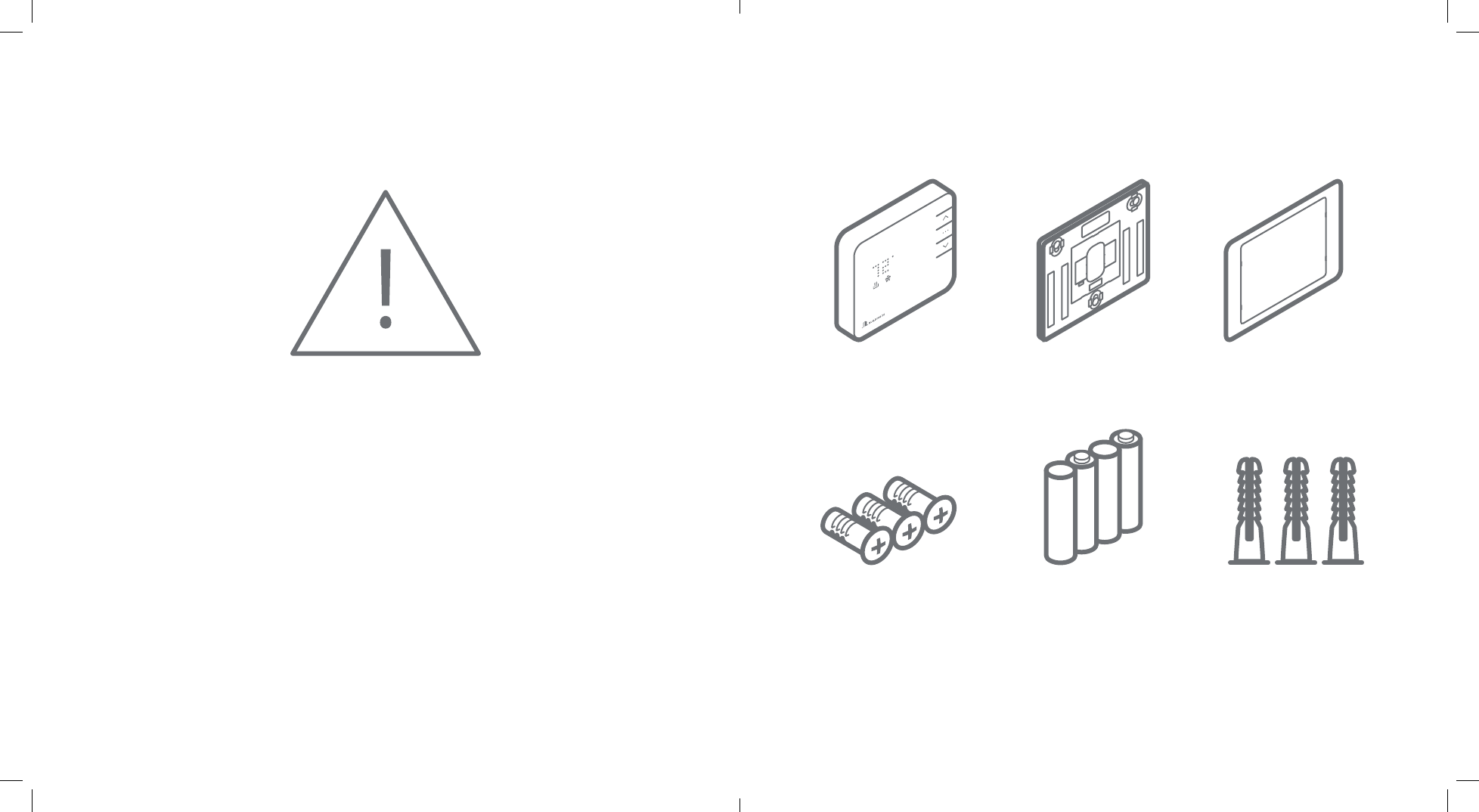
Thermostat Backplate Trim Plate (Optional)
• Before installing or servicing
your thermostat, turn o
power to the system at
circuit breaker.
• Leave power o until
nished installing or
servicing.
• Shorting the electric
terminals at the control
on the heating or cooling
system may damage the
thermostat. Do not test the
system this way.
• You must follow all local
codes and ordinances for
wiring your system.
• This thermostat should only
be powered by 4AA alkaline
batteries or a Listed class
2 power supply at 24 VAC
(C-Wire or wall transformer).
• An amperage higher than 1
amp to each thermostat
relay load may cause
damage to the thermostat.
• To avoid electrical shock
and to prevent damage
to the HVAC system and
thermostat, disconnect
the power supply before
installing or servicing. It is
recommended this be done
at the circuit breaker.
Drywall Screws (3) AA Batteries (4) Drywall Anchors (3)
• Needlenose Pliers • Phillips Screwdriver • Power Drill • Pencil
Contents:
Recommended Tools:
4 | Intelligent Thermostat User Guide Intelligent Thermostat User Guide | 5
Operation
Display
• Press any button to wake the thermostat up.
• After waking, the display will show the current
mode and room temperature.
• IF the system is running the display will
wave up for heating or down for cooling.
• Press the up or down button once to change to
display current setpoint.
• The currently illuminated MODE icon will
being to pulse.
• Press the up or down button again to adjust the
setpoint.
• Press the mode button at any time to change
the mode.
• The modes are HEAT, COOL, AUTO, and OFF.
• The thermostat will display the mode
appropriate setpoint.
• In AUTO, the brighter icon will indicate which
setpoint is currently displayed and active (HEAT
or COOL).
• After 5 seconds the display will return to
the current room temperature. The MODE
icon will become solid to indicate this. After 5
more seconds the display will turn o and the
thermostat will sleep.
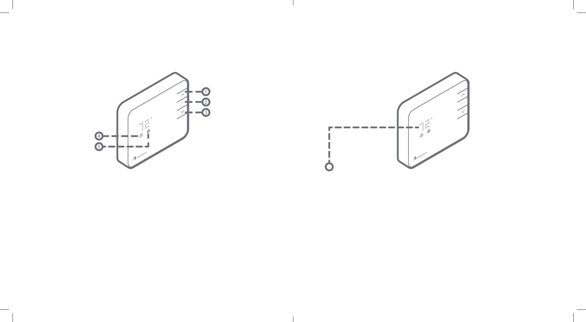
Buttons
1. UP Button – Adjust target temperature up.
2. MODE Button – Change thermostat from
HEAT, COOL, AUTO, and OFF modes.
3. DOWN Button – Adjust target temperature/
(un)Pair to and from network.
Icons
4. HEAT Icon – Illuminated in HEAT or AUTO
mode.
5. COOL Icon – Illuminated in COOL or AUTO
mode.
6 | Intelligent Thermostat User Guide Intelligent Thermostat User Guide | 7
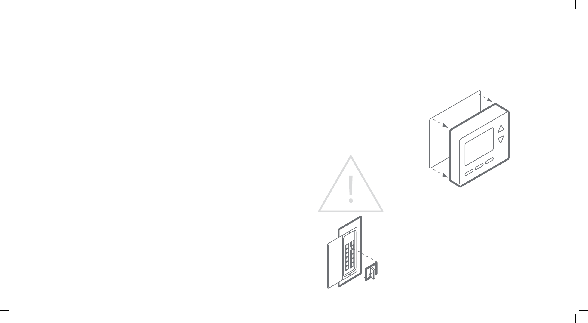
Location: Removing Existing Thermostat:
If replacing an old thermostat,
the new thermostat will be
mounted in place of the old.
If a new location is desired
it will be necessary to move
your wiring.
New installations and
relocation should follow
the guidelines below
to ensure the most accurate
temperature reading and ease
of use.
• Mount thermostat on an
inside wall, approximately 5
ft. (1.5m) above the oor in a
frequently used room.
• Do not install in locations
near appliances or
devices that aect the
local temperature such as
televisions, lamps, or dryers.
• Avoid areas that are exposed
large temperature variances,
such as: direct sunlight, near
an AC unit, above or below
auxiliary heat and air vents,
and drafts from windows.
• Be aware of what is on the
other side of the wall the
thermostat is being installed
on. Do not install on walls
adjacent to unheated rooms,
stoves, or housing hot water
pipes.
• Damp areas will not only
aect the humidity reading
of your thermostat, but could
lead to corrosion shortening
the life of your thermostat.
• Install in a location with good
air circulation. Stagnant air
will not accurately reect the
rate of change of temperature
in the room. Avoid areas
behind open doors, corners,
and alcoves.
• Wait until construction and
painting are nished before
installing.
Test your system
Verify that your heating and/
or cooling system is operating
properly before you try to
install your new thermostat.
DO NOT do so by shorting
(jumper) across electric
terminals at the furnace or air
conditioner. This may damage
the thermostat.
DO NOT REMOVE your
existing thermostat until
power has been turned o
at the circuit breaker.
Once power to the heating AND cooling systems is o follow these
steps:
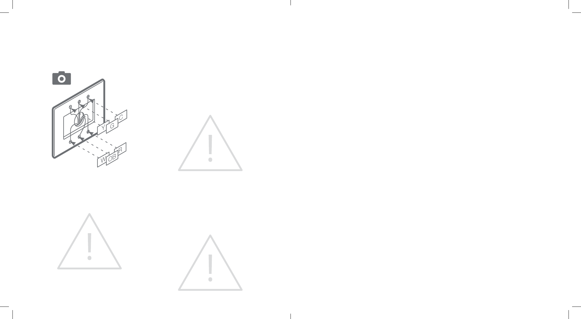
• Remove cover from your existing thermostat. Do not disconnect
the wires yet.
TIP: Take a picture of the wires before you detach them from the
existing thermostat.
• Label all existing wires, one at a time, with the labels provided.
8 | Intelligent Thermostat User Guide Intelligent Thermostat User Guide | 9
Install Your New ThermostatRemoving Existing Thermostat:
• Disconnect all of the wires and remove the
existing thermostat.
TIP: Remember to secure the wires so they don’t
fall into the wall.
CAUTION: Wiring can vary for each
manufacturer. Label all wiring before removing
it from your existing thermostat.
What wires does your system use?
Make sure your wires are labeled correctly. It may
be necessary to nd the ‘other end’ connection
for each wire on your heating or air conditioning
equipment and read the label there.
IMPORTANT: This thermostat runs on batteries
and the C wire. If you do not have a C wire you
can run a new wire from the HVAC or use a
standard 24VAC wall transformer
Prepare the wires
Please follow these guidelines for safe and
secure wire connections:
• Ensure the wires are a proper gauge.
• Make sure wires have exposed straight ends
about 1/8” long.
CAUTION: Verify that your system is 24 VAC. If
your old system is labeled as 120 or 240 volts, or
has wire nuts your system is high voltage. Do not
install your thermostat to a high voltage system.
Contact your local HVAC professional for help.
Install the back plate
Use the bubble level provided
on the back plate as a guide.
Mark where the screws will
go with a pencil through the
screw holes on the back plate.
TIPS:
• Use the trim plate to cover
up any marks or holes left
from the old thermostat.
Attach the trim plate before
securing the back plate to
the wall.
• Drill holes with 3/16” drill bit
to tap in the drywall anchors
for added support.
Wire your new thermostat
Go to page 8 to nd the wiring diagram that matches your wiring
and insert the wires into the back plate.
TIP: Anything that wasn’t connected to your old thermostat
shouldn’t be connected to your new thermostat either. You may
also have extra wires that do not match. Leave them as is.
EXCEPTIONS:
• If you have R, connect it to RH.
• If you have RH & RC remove black jumper in lower left corner of
back plate terminal board.
• Z can be used for W3, H, or DH.
10 | Intelligent Thermostat User Guide Intelligent Thermostat User Guide | 11
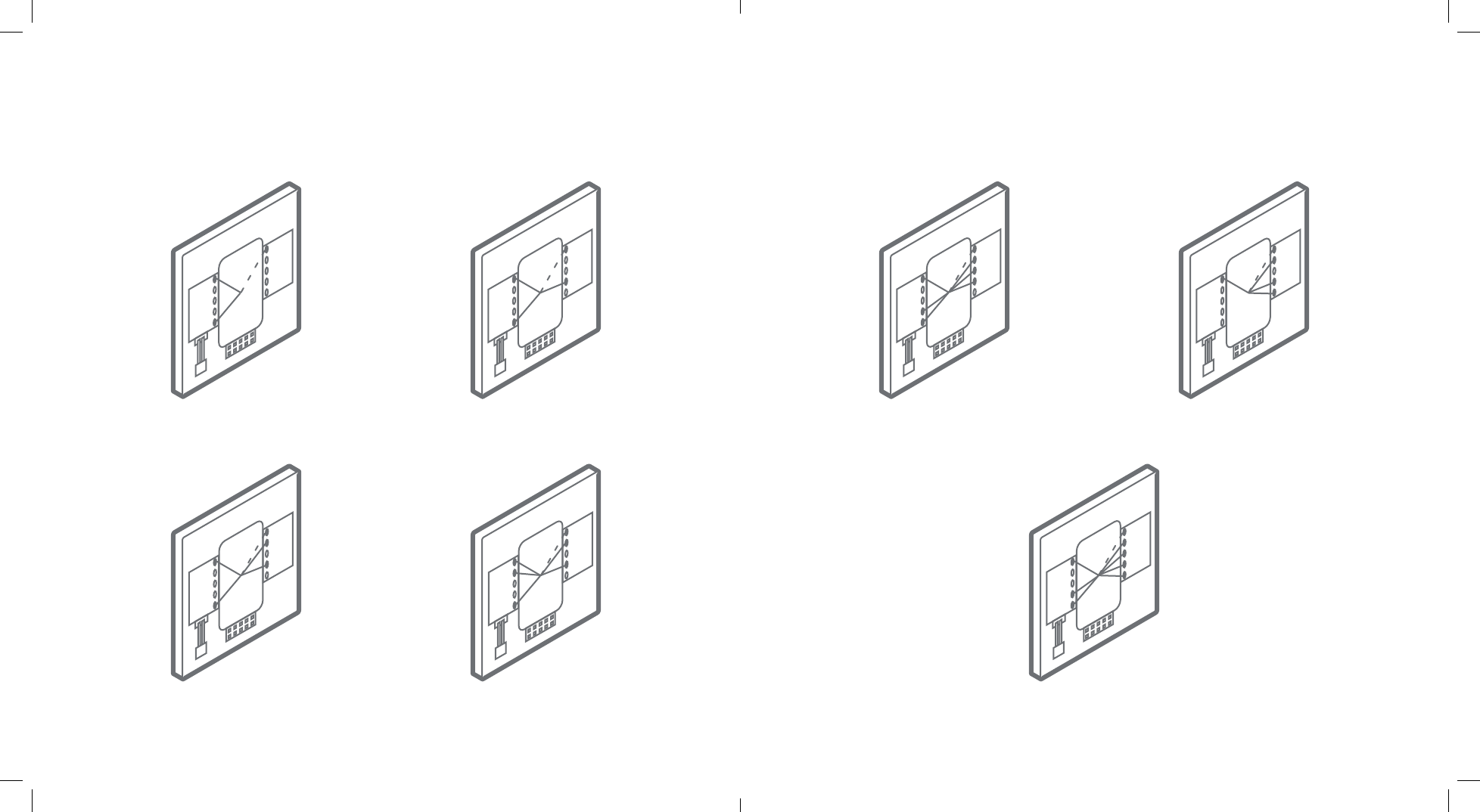
Wiring Diagrams:
RH
RC
Z
W2
W
C
Y
Y2
G
OB
Conguration 1
RH, W
Conguration 2
RH, W, G
Conguration 5
RH, G, W, W2, Y, Y2
Conguration 6
RH, G, OB, Y
Conguration 3
RH, W, Y, G
Conguration 4
RH, RC, G, W, Y
Conguration 7
RH, G, W, W2, Y, Y2, OB
RH
RC
Z
W2
W
C
Y
Y2
G
OB
RH
RC
Z
W2
W
C
Y
Y2
G
OB
RH
RC
Z
W2
W
C
Y
Y2
G
OB
RH
RC
Z
W2
W
C
Y
Y2
G
OB
RH
RC
Z
W2
W
C
Y
Y2
G
OB
RH
RC
Z
W2
W
C
Y
Y2
G
OB
12 | Intelligent Thermostat User Guide Intelligent Thermostat User Guide | 13
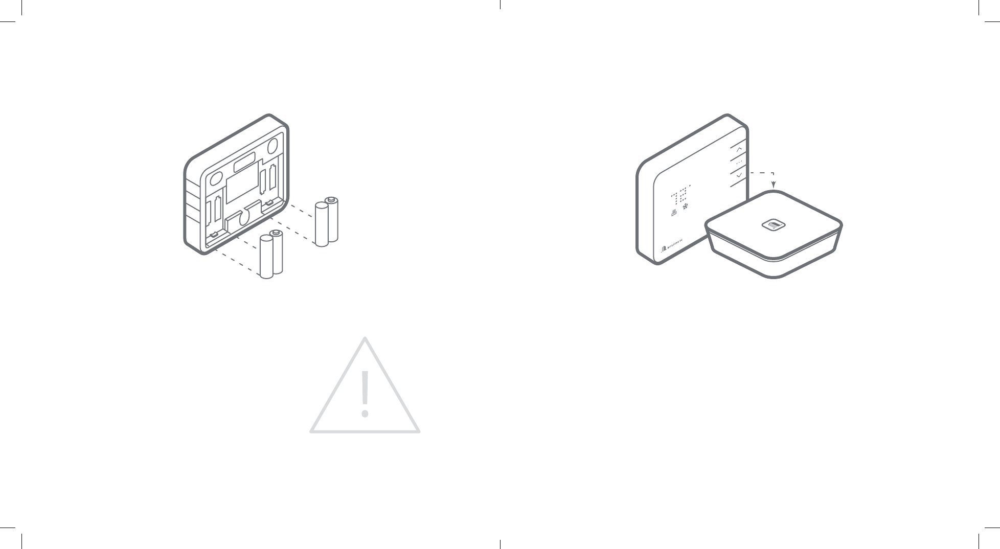
Insert batteries into Thermostat body Connect the Thermostat to the Gateway
The thermostat can be powered by battery or 24
VAC. If a wall transformer is used to power your
thermostat connect between C and RH.
Ensure the batteries are installed following the
specied polarity markings on the thermostat.
CAUTION: Special Battery Warning
• Always replace the batteries as soon as Low
Battery is indicated. If the batteries die, your
thermostat could leave the HVAC system on,
overheating or freezing your home.
• Always replace the batteries at least once a year.
This will protect your thermostat from damage
and corrosion by leaking batteries.
• If your home is unoccupied for a month or more,
such as vacation homes, you should replace
the batteries as a preventive measure against
battery failure while you are away.
• Use only new batteries when changing.
• Bring Gateway to the Thermostat.
• Put the thermostat in OFF mode (No mode icons are lit).
• Press the inclusion button on the Gateway.
• Press and hold the DOWN button the thermostat to begin pairing. The RADIO icon should start
blinking.
• When the RADIO icon becomes solid, the thermostat is joined to the network.
• Login to your account to sync your thermostat with the Building 36 system, or contact your local
professional for installation setup.
14 | Intelligent Thermostat User Guide Intelligent Thermostat User Guide | 15
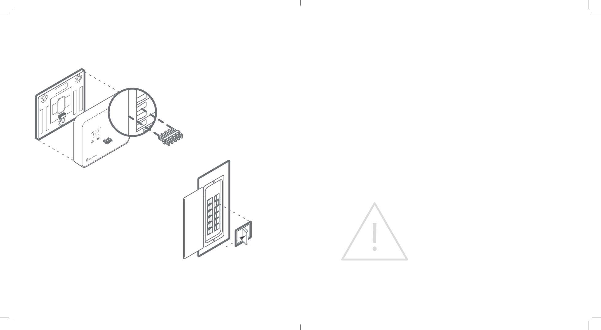
Install Thermostat body to back plate
Press the thermostat body rmly into the back
plate mounted to the wall. Ensure that the
pins on the body are correctly aligned with the
header attached to the terminal board on the
back plate. Failure to do so could cause damage
to the thermostat.
Turn the power on
Restore power to your heating and cooling
system. This can be done at the circuit breaker.
Congure Your System Check Your System
Your thermostat conguration will be done
online at the customer site on your customer
account page. Here you will congure the
parameters of your system, such as: Heat
Pump or Normal, number of heat and cool
stages, heating fuel, calibration temperature,
and congurable terminal (Z). Refer to your
conguration number on the wiring diagrams
page to see the values you should enter on the
online conguration.
This is also were you have the option to change
advanced conguration settings, such as: Swing,
Dierential, Recovery Setting, Fan Circulation
Period and Duty Cycle, Maximum Setpoints,
Minimum Setpoints, Thermostat Lock, Demand
Response Delay, Demand Response Duty Cycle,
and Modes Enabled.
WARNING: Use caution when changing
advanced conguration settings. These
conguration settings should only be changed
by those familiar with heating and cooling
systems’ parameters. Contact your local HVAC
professional for help.
For denitions of these settings and more
information go to www.building36.com
By default the thermostat is congured to 2 heat
stages and 2 cool stages (2 Heat Pump, 2 Aux).
To check heating
Press the MODE button to select HEAT mode.
• Press UP button to raise setpoint above room
temperature.
• Wait 10 seconds for system to turn on.
• After verify the heating system is working,
raise the setpoint to the desired temperature.
To check cooling
Press MODE button to select COOL mode.
• Press DOWN button to lower setpoint below
room temperature.
• Wait 10 seconds for system to turn on.
• After verify cooling system is working, lower the
setpoint to the desired temperature.

16 | Intelligent Thermostat User Guide Intelligent Thermostat User Guide | 17
Troubleshooting
Batteries die quickly
If a thermostat is paired using a C-Wire, that
information is saved in the network and cannot
be changed unless removed and paired again
without a C-Wire connected. The same applies
for inclusions on battery power. If you nd your
thermostat batteries are dying unusually quick,
check and make sure the C-Wire connection
is still intact. If a device is paired using C-Wire
the Z-Wave communication never sleeps and
the thermostat will act a repeater, sending
messages for other devices as well. If the C-Wire
is removed this kind of activity will drain the
battery very quickly.
Manual conguration of HVAC system on
thermostat
The system type (Normal or Heat Pump) can be
physically set on the thermostat if necessary by
doing the following:
1. Put thermostat in OFF mode.
2. Press and hold the UP button.
3. Press UP or DOWN buttons to select either
‘HP’ for heat pump conguration or ‘NORM’ for
normal conguration.
4. Press MODE button to conrm your selection.
Exclusion of thermostat from Z-Wave
network
If for some reason the thermostat must be
removed from the network, follow the steps
below to do so.
1. Press and hold the exclusion button on the
gateway.
2. Press and hold the DOWN button the
thermostat to enter exclusion mode. The
RADIO icon will begin ashing red.
3. When the RADIO icon becomes solid the
thermostat has now been successfully
removed from the network.
Heat pump is cooling when it should be
heating
Because both types of heat pump reversing
valves share a single terminal on your thermostat
back plate, you need to be sure you have the
thermostat congured for the correct wire. Try
switching your O/B selection on the customer
thermostat conguration page. Contact your
local HVAC professional for further with this issue.
The same applies to a heat pump that is heating
when it should be cooling.
Heating or cooling doesn’t turn on when the
target is set above or below the ambient
The thermostat is congured to have a minimum
setting of a half degree dierence in temperature
from the target before the system turns on
to protect the system from damage due to
excessive use. The cooling system also has a built
in compressor delay. Each time compressor is
turned on, a large amount of pressure is built up
and must be equalized. This delay time prevents
damage to the compressor from not allowing
this pressure to equalize before being turned
on again. For more help contact your local HVAC professional or Building 36 Technologies.

18 | Intelligent Thermostat User Guide Intelligent Thermostat User Guide | 19
Notices
FCC NOTICE:
This device complies with part 15 of the FCC
Rules. Operation is subject to the following two
conditions:
1. This device may not cause harmful interference.
AND
2. This device must accept any interference
received, including Interference that may cause
undesired operation.
This equipment has been tested and found
to comply with the limits for a Class B digital
device, pursuant to part 15 of the FCC
Rules. These limits are designed to provide
reasonable protection against harmful
interference in a residential installation.
This equipment generates, uses and can
radiate radio frequency energy and, if not
installed and used in accordance with the
instructions, may cause harmful interference
to radio communications. However, there is
no guarantee that interference will not occur
in a particular installation. If this equipment
does cause harmful interference to radio or
television reception, which can be determined
by turning the equipment o and on, the user
is encouraged to try to correct the interference
by one or more of the following measures:
Reorient or relocate the receiving antenna.
Increase the separation between the equipment
and receiver. Connect the equipment into an
outlet on a circuit dierent from that to which
the receiver is connected. Consult the dealer or
an experienced radio/TV technician for help.
NOTE: THE GRANTEE IS NOT RESPONSIBLE FOR ANY CHANGES OR MODIFICATIONS NOT EXPRESSLY
APPROVED BY THE PARTY RESPONSIBLE FOR COMPLIANCE. SUCH MODIFICATIONS COULD VOID
THE USER’S AUTHORITY TO OPERATE THE EQUIPMENT.
Under Industry Canada regulations, this radio
transmitter may only operate using an antenna
of a type and maximum (or lesser) gain approved
for the transmitter by Industry Canada. To reduce
potential radio interference to other users, the
antenna type and its gain should be so chosen
that the equivalent isotropically radiated power
(e.i.r.p.) is not more than that necessary for
successful communication.
Conformément à la réglementation d’Industrie
Canada, le présent émetteur radio peut fonctionner
avec une antenne d’un type et d’un gain maximal
(ou inférieur) approuvé pour l’émetteur par
Industrie Canada. Dans le but de réduire les risques
de brouillage radioélectrique à l’intention des
autres utilisateurs, il faut choisir le type d’antenne
et son gain de sorte que la puissance isotrope
rayonnée équivalente (p.i.r.e.) ne dépasse pas
l’intensité nécessaire à l’établissement d’une
communication satisfaisante.