Building 36 Technologies B36T20RA SMART THERMOSTAT 2 User Manual
Building 36 Technologies, LLC SMART THERMOSTAT 2
User Manual

ADC-T3000
SMART THERMOSTAT 2
Product Manual

SMART THERMOSTAT 2 Product Manual | 1
• Before installing or servicing the thermostat, turn o
power to the system at the circuit breaker.
• Leave power o until you have nished installing
or servicing.
• Shorting the electric terminals at the control on the
heating or cooling system may damage the thermostat.
Do not test the system this way.
• You must follow all local codes and ordinances for wiring
the system.
• This thermostat should only be powered by 2 AAA alkaline
batteries or a listed class 2 power supply at 24 VAC
(C-Wire or wall transformer).
• An amperage higher than 1 amp through each thermostat
terminal may cause damage to the thermostat.
• Verify that the system is 24 VAC. If the old system is labeled
as 120 or 240 volts or has wire nuts, the system is high
voltage. Do not install the thermostat to a high voltage
system. Contact a local HVAC professional for help.
2 | SMART THERMOSTAT 2 Product Manual SMART THERMOSTAT 2Product Manual | 3
AAA
AAA
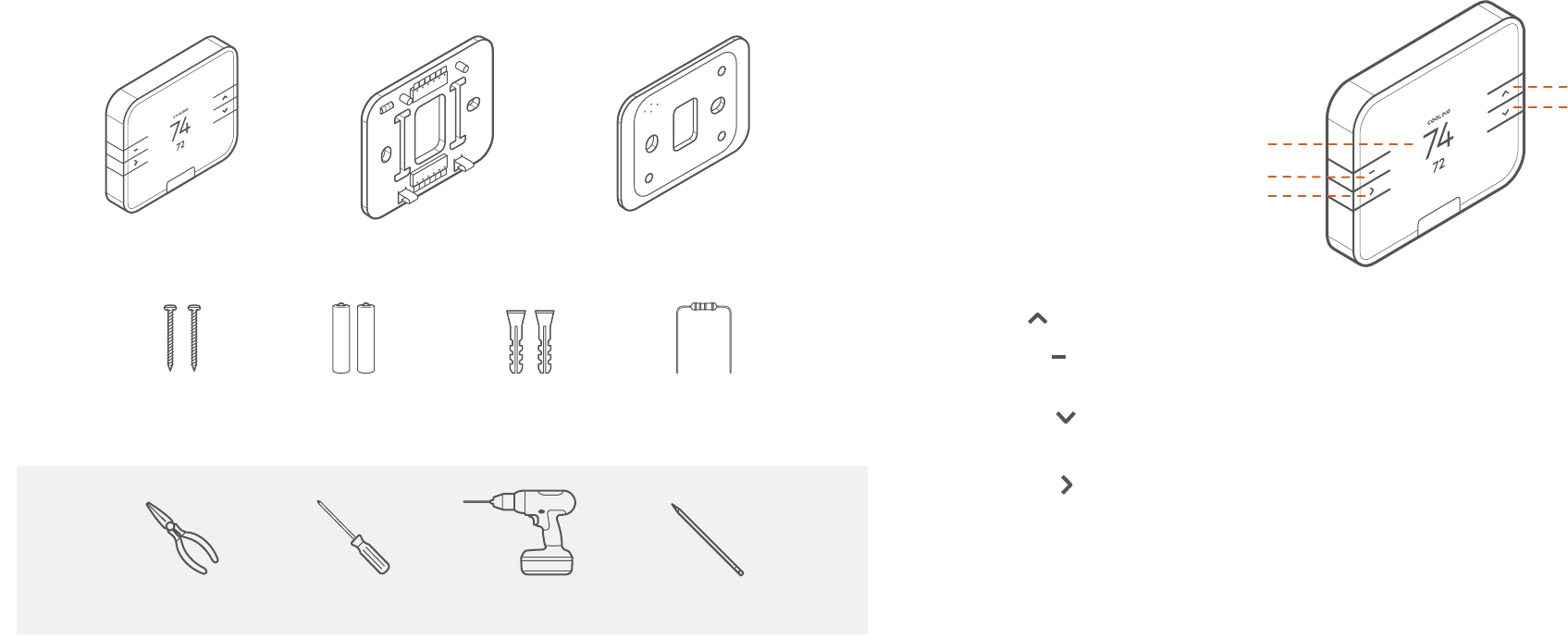
Thermostat Backplate Trim Plate (Optional)
Drywall Screws (2) AAA Batteries (2) Drywall Anchors (2) Power Resistor
BOX CONTENTS
RECOMMENDED TOOLS
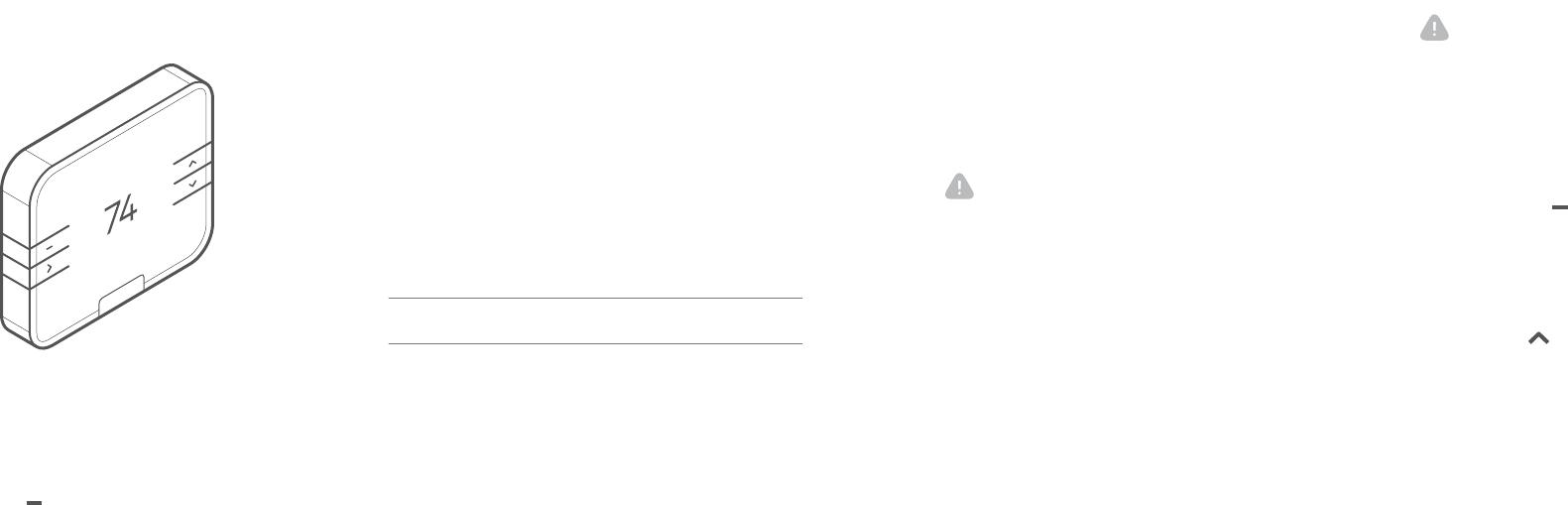
THERMOSTAT OVERVIEW
Buttons
• UP – Adjust target temperature up or navigate the MENU.
• MENU – Access MENU options to change the mode, fan,
settings, and other features.
• DOWN – Adjust target temperature down or navigate
the MENU.
• SELECT – Select options in the MENU. Can also be
congured to control other features.
Modes
• HEAT - Will activate the heating system.
• COOL - Will activate the air conditioner.
• AUTO - Will select either the HEAT or COOL
mode automatically.
• EMER - For use with heat pumps only. Will bypass the
heat pump and enable the auxiliary/emergency heat.
• OFF - The system will not heat or cool.
Display
• HEATING – Illuminated in HEAT, EMER or AUTO mode
when the thermostat is calling for heat.
• COOLING – Illuminated in COOL or AUTO mode when
the thermostat is calling for cool.
MENU
SELECT
UP
DOWN
Power Drill
Needlenose Pliers Pencil
Phillips Head
Screwdriver
DISPLAY
4 | SMART THERMOSTAT 2 Product Manual SMART THERMOSTAT 2Product Manual | 5
LOCATION
If replacing an old thermostat, the new
thermostat can be mounted in its place.
If a new location is desired it will be
necessary to move the wiring.
New installations and relocation should
follow the accompanying guidelines to
ensure the most accurate temperature
reading and ease of use.
• Mount thermostat on an inside wall,
approximately 5 ft. (1.5m) above the
oor in a frequently used room.
• Do not install in locations near
appliances or devices that aect the
local temperature such as televisions,
lamps, or dryers.
• Avoid areas that are exposed to
large temperature variances, such as:
direct sunlight, near an AC unit,
above or below auxiliary heat and air
vents, and drafts from windows.
• Be aware of what is on the other side
of the wall where the thermostat is
being installed. Do not install on walls
adjacent to unheated rooms, stoves,
or housing hot water pipes.
• Damp areas will not only aect the
humidity reading of the thermostat,
but could lead to corrosion and
shorten the life of the thermostat.
• Install in a location with good
air circulation. Stagnant air will
not accurately reect the rate of
temperature change in the room.
Avoid areas behind open doors,
corners, and alcoves.
• Wait until construction and painting
are nished before installing.
PREPARATION
The Existing Thermostat
1. Test The System
Verify that the heating and/or cooling system is operating
properly before you try to install the new thermostat.
DO NOT test the system by shorting electric terminals at the
furnace or air conditioner. This may damage the thermostat.
2. Turn Power O
• Turn all heating and cooling systems o. This can be done
at the circuit breaker.
CAUTION: DO NOT REMOVE the existing thermostat
until power has been turned o at the circuit breaker.
Once power to the heating AND cooling systems is o,
follow these steps:
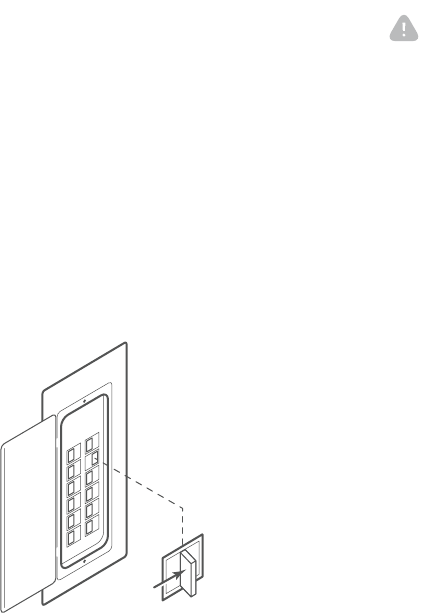
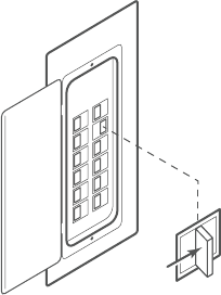
3. Remove Thermostat Cover
• Remove the cover from the existing thermostat.
Do not disconnect the wires yet.
Make sure the wires are identied correctly. If you
have an unidentied wire, it may be necessary to
identify the wire where it connects to the heating or
air conditioning equipment.

6 | SMART THERMOSTAT 2 Product Manual SMART THERMOSTAT 2 Product Manual | 7
Install the Back Plate
Use the bubble level provided on the back plate as a guide.
Mark where the screws will go with a pencil through the
screw holes on the back plate. Ensure the top of the
back plate is facing up.
TIP: If necessary, use the trim plate to cover up any
marks or holes left from the old thermostat. Attach the
trim plate before securing the back plate to the wall.
TIP: Drill holes with 1/4” drill bit to tap in the
drywall anchors for added support.
Wire Your New Thermostat
Reconnect the wires to the new thermostat.
TIP: If you have extra wires do not install them
in the new thermostat. Please contact your local
HVAC professional for additional assistance.
• If you have R, connect it to RH.
• Z1 or Z2 can be used for W3, H, DH, or EX.
NOTE: If you have a 2-wire system (most common)
or hydronic heating system, you must add the Power
Resistor to the system. Connect this resistor at your
heating equipment between the C and W terminals.
CAUTION: Verify that the system is 24 VAC. If the old
system is labeled as 120 or 240 volts or has wire nuts,
the system is high voltage. Do not install the thermostat
to a high voltage system. Contact a local HVAC
professional for help.
CAUTION: Wiring can vary for each manufacturer.
Identify all wiring before removing it from the
existing thermostat.
TIP: Take a picture of the wires before you detach
them from the existing thermostat for
future reference.
• Disconnect all of the wires and remove the existing
thermostat.
TIP: Remember to secure the wires so they don’t
fall into the wall.
Prepare the Wires
Follow these guidelines for safe and secure
wire connections:
• Ensure the wires are a proper gauge
between18-24 AWG.
• Make sure wires have exposed straight ends
about 1/8” long.
INSTALL YOUR NEW THERMOSTAT
SMART THERMOSTAT 2Product Manual | 9
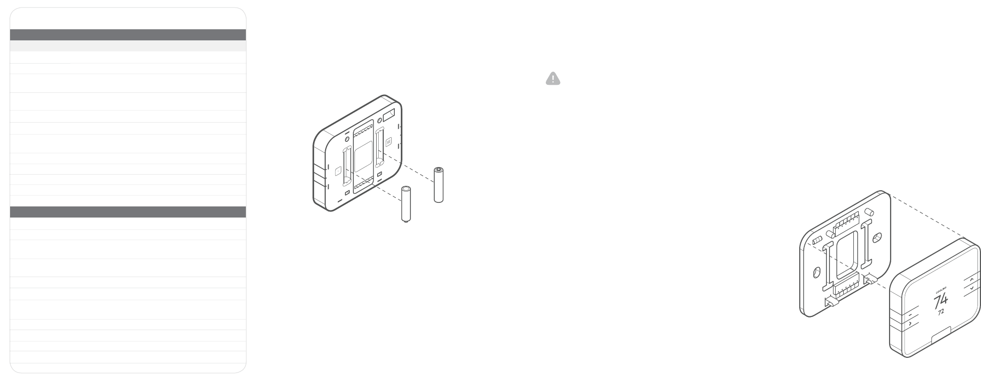
Install Thermostat Body to Back Plate
Verify that any excess wire is tucked back into the wall to allow
room for the thermostat to sit ush against the back plate.
Return the thermostat to the wall plate by pressing the thermostat
body rmly into the back plate mounted to the wall. Ensure that
the pins on the body are correctly aligned with the back plate.
Failure to do so could cause damage to the thermostat.
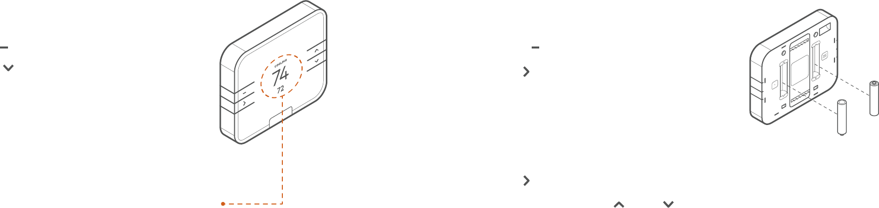
Insert Batteries Into the Thermostat
The thermostat can be powered by battery or 24 VAC.
If a wall transformer is used to power the thermostat,
connect between C and RH.
Ensure the batteries are installed following the specied
polarity markings on the thermostat.
Terminal Designations
CONVENTIONAL SYSTEM
Terminal Description
RC Cooling power
RH Heating power
ZCongurable W3, H (humidier control), DH (dehumidifier control),
EX (vent, external air baffle, ERV/HRV)
Z2 Congurable W3, H (humidier control), DH (dehumidifier control),
EX (vent, external air baffle, ERV/HRV)
WHeat stage 1
W2 Heat stage 2
C Common wire from secondary sid of heating transformer
(if 2 transformers)
Y Cool stage 1
Y2 Cool stage 2
G Fan
O Energized in Cool mode
B Energized in Heat mode
HEAT PUMP
RC Cooling power
RH Heating power
ZCongurable W3, H (humidier control), DH (dehumidifier control),
EX (vent, external air baffle, ERV/HRV)
Z2 Congurable W3, H (humidier control), DH (dehumidifier control),
EX (vent, external air baffle, ERV/HRV)
WAux stage 1
W2 Aux stage 2
C Common wire from secondary side of heating transformer
(if 2 transformers)
Y Pump stage 1
Y2 Pump stage 2
G Fan
O Energized in Cool mode
B Energized in Heat mode
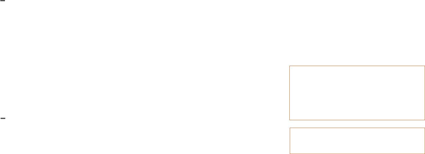
CAUTION: Special Battery Warning
• Always replace the batteries as soon as you have low
battery levels, indicated by a caution sign and “LOW
BATTERY” ashing on the display. If the batteries drain,
the thermostat could leave the HVAC system on or o,
overheating or freezing the home.
• Always replace the batteries when they are low to
protect the thermostat from damage and corrosion
by leaking batteries.
• If the home is unoccupied for a month or more,
such as vacation homes, you should replace the
batteries as a preventive measure against battery
failure while you are away.
• Always use new batteries as replacements.
8 | SMART THERMOSTAT 2Product Manual
10 | SMART THERMOSTAT 2 Product Manual SMART THERMOSTAT 2 Product Manual | 11
Fan on During Heating
Tells the thermostat whether the fan should be on during
a heating cycle.
• Forced Air Heating - Yes
• Radiant Floor Heating - No
• Fossil/Electric Baseboard Heating - No
• Radiators - No
• If Unsure - Not sure
Backup Heat Type
Tells the thermostat what type of auxiliary/backup heating
the heat pump uses.
• Electric - This is the most common type of
backup heating.
• Dual Fuel - Some heat pumps use a fossil furnace
(for example, natural gas, oil, or propane)
or backup heating.
• If Unsure - The system will automatically detect
which heat type is appropriate for your system.
Z1/Z2 Terminal Function
These are the “dynamic” terminals. If an auxiliary wire has
been connected, please specify the function it will perform.
• W3 - Third stage of heat or aux
• H - Humidier
• DH - Dehumidier
• EX - Vent (external air bae)
THERMOSTAT SETUP
• Thermostat will automatically detect the connected wires.
• Follow the on-screen instructions to complete the
thermostat conguration.
NOTE: If the thermostat screen does not show all the
connected wires, remove the thermostat from the wall
and verify that all wires are properly connected. If issues
persist, there may be an HVAC problem. Please contact
an HVAC service provider for assistance.
Depending on the system type and conguration, the
thermostat may request the following information
during setup:
Turn the Power On
Restore power to all the heating and cooling systems.
This can be done at the circuit breaker.
12 | SMART THERMOSTAT 2 Product Manual SMART THERMOSTAT 2 Product Manual | 13
CHECK THE SYSTEM
WARNING: Do not test the AC during cold weather or
heat during hot weather. Wait for mild weather to
fully test the system.
To Check Heating
1. Press the MENU button to select and use
UP/DOWN to scroll to MODE. Press SELECT to choose
the mode option. Use UP/DOWN to scroll to HEAT.
Press SELECT to choose the HEAT option.
2. Press the UP button to raise the setpoint
above room temperature.
3. Wait 5 minutes for the system to turn on.
4. After verifying the heating system is working,
return the setpoint to the desired temperature.
Connect the Thermostat to the System
1. Put the thermostat in OFF mode.
2. Put the Z-Wave controller into ADD mode. Refer to the
controller documentation for more information.
3. Press the MENU button
4. Select SETTINGS
5. Select NETWORK
6. Select ADD
7. Log in to your online account to sync the thermostat
with the account, or contact your Service Provider for
installation setup.
Write your login information below once you
have chosen a personal password.
User ID:
Password:
CONFIGURE THE SYSTEM
While the default settings online will be sucient in
most cases, you also have the option to change advanced
conguration settings, such as: Swing, Dierential,
Recovery Setting, Fan Circulation Period and Duty Cycle,
Maximum Setpoints, Minimum Setpoints and
Thermostat Lock.
WARNING: Use caution when changing advanced
conguration settings. These conguration settings
should only be changed by those familiar with heating
and cooling systems’ parameters. Contact a local
HVAC professional for help.
14 | SMART THERMOSTAT 2 Product Manual SMART THERMOSTAT 2 Product Manual | 15
If the thermostat batteries are low, replace the batteries
with two new AAA batteries.
1. Remove the thermostat from the back plate by pulling
the thermostat straight out and o the wall.
2. Take out the existing batteries.
3. Insert the new batteries following the specied polarity
markings on the thermostat.
4. Return the thermostat to the wall plate by pressing the
thermostat body rmly into the back plate mounted
to the wall. Ensure that the pins on the body are correctly
aligned with the back plate. Failure to do so could cause
damage to the thermostat.
CHANGING THE BATTERIES
Display
Waking the Device
1. Press any button to wake the thermostat up.
2. After waking, the display will show the current mode,
room temperature, and setpoint.
OPERATION
Changing the Mode and Setpoint
1. Press the MENU button to access the menu screen.
2. Press SELECT on the MODE option.
• The modes are HEAT, COOL, AUTO, EMER and OFF.
• EMER mode is available for Heat Pump systems.
• When in EMER mode, the display will read EMER when
the thermostat wakes up and the HEAT icon will be
displayed. Changing the mode will leave EMER mode.
3. Press SELECT on the desired mode.
4. Once in the desired mode, press the UP or DOWN
button to adjust to the desired setpoint.
• In AUTO mode when the system is idle, the screen will
display AUTO. The thermostat will display HEATING when
calling for heat and COOLING when calling for cool.
To Check Cooling
1. Press the MENU button to select COOL mode.
2. Press the DOWN button to lower the setpoint
below room temperature.
3. Wait 5 minutes for the system to turn on.
4. After verifying the cooling system is working,
return the setpoint to the desired temperature.
16 | SMART THERMOSTAT 2 Product Manual SMART THERMOSTAT 2 Product Manual | 17
NOTICES
FCC
This device complies with part 15 of the FCC Rules Operation is subject to the
following two conditions:
1. This device may not cause harmful interference.
and
2. This device must accept any interference received, including interference
that may cause undesired operation.
This equipment has been tested and found to comply with the limits
for a Class B digital device, pursuant to part 15 of the FCC Rules. These
limits are designed to provide reasonable protection against harmful
interference in a residential installation. This equipment generates, uses
and can radiate radio frequency energy and, if not installed and used in
accordance with the instructions, may cause harmful interference to radio
communications. However, there is no guarantee that interference will
not occur in a particular installation. If this equipment does cause harmful
interference to radio or television reception, which can be determined by
turning the equipment o and on, the user is encouraged to try to correct
the interference by one or more of the following measures:
• Reorient or relocate the receiving antenna.
• Increase the separation between the equipment and receiver.
• Connect the equipment into an outlet on a circuit dierent from that to
which the receiver is connected.
• Consult the dealer or an experienced radio/TV technician for help.
IC
This device complies with Industry Canada licence-exempt RSS standard(s). Operation is
subject to the following two conditions: (1) this device may not cause interference, and (2) this
device must accept any interference, including interference that may cause undesired operation
of the device.
Le présent appareil est conforme aux CNR d'Industrie Canada applicables aux appareils radio
exempts de licence. L'exploitation est autorisée aux deux conditions suivantes : (1) l'appareil ne
doit pas produire de brouillage, et (2) l'utilisateur de l'appareil doit accepter tout brouillage
radioélectrique subi, même si le brouillage est susceptible d'en compromettre le fonctionnement.
The device has been evaluated to meet general RF exposure requirement. To maintain
compliance with RSS-102 — Radio Frequency (RF) Exposure guidelines, this equipment should
be installed and operated with a minimum distance of 20cm between the radiator and your body.
le dispositif de a été évalué à répondre général rf exposition exigence.pour maintenir la
conformité avec les directives d'exposition du RSS-102-Radio Fréquence (RF). ce matériel doit
être installé et exploité à une distance minimale de 20 cm entre le radiateur et votre corps.
Note: The grantee is not responsible for
any changes or modications not expressly
approved by the party responsible for
compliance. Such modications could void
the user’s authority to operate the equipment.
For more help, contact your
Service Provider.
TROUBLESHOOTING
Heating or Cooling Doesn’t Turn On When the Setpoint is
Above or Below the Room Temperature
To prevent damaging the compressor, the thermostat inserts
a delay when cycling the compressor. If you think the system
should be on and it’s not, then change the setpoint to be
2 degrees beyond the current setpoint and wait 5 minutes
to see if the system turns on. If not, contact a local
HVAC professional.
Heat Pump is “Cooling When it Should be Heating” or
“Heating When it Should be Cooling”
Some heat pumps use the O terminal, while others use the B
terminal. Try switching the O or B wire to the opposite terminal.
Contact a local HVAC professional for further assistance.
Thermostat Buttons Flash Red and Screen
Will Not Illuminate
The batteries in your thermostat are extremely low. Replace
the batteries with fresh batteries immediately.
Accessing the INSTALLER (Setup) Menu
The initial setup menu can be accessed at any time:
1. Press the MENU button
2. Select SETTINGS
3. Select INSTALL
Exclude the Thermostat From the Z-Wave Network
If for some reason the thermostat must be excluded
from the network, follow the steps below to do so.
1. Set the thermostat to OFF mode.
2. Put the Z-Wave controller into Delete mode. Refer to
the controller documentation formore information.
3. Press the MENU button
4. Select SETTINGS
5. Select NETWORK
6. Select REMOVE. Follow the on-screen instructions.
The device has been evaluated to meet general RF exposure requirement.
To maintain compliance with FCC's RF exposure guidelines, the distance must be at
least 20 cm between the radiator and your body, and fully supported by the operating
and installation configurations of the transmitter and its antenna(s).

www.Alarm.com
© 2018 Alarm.com. All rights reserved. Designed in the USA by Building 36, an Alarm.com company.
180724 v2.0