Bully Dog 153001 Users Manual
2015-02-02
: Bully-Dog Bully-Dog-153001-Users-Manual-485825 bully-dog-153001-users-manual-485825 bully-dog pdf
Open the PDF directly: View PDF ![]() .
.
Page Count: 8
INSTALLATION MANUAL
Applications Rapid Power Part #
GM Duramax w/ auto trans ‘01-’05 153001
Stage 1 Shift Enhancer

1
TROUBLESHOOTING:
Technical support is available by calling 866-bullydog
(866-285-5936).
TABLE OF CONTENTS
INTRODUCTION
Get ready for greatly improved shift over stock shifting, this stage 1 shift enhancer will give you a noticeably better
shift with a more positive engage. Before begining installation be sure that the truck has sat long enough for the
transmission to completely cool down.
TABLE OF CONTENTS
INTRODUCTION ...............................................................................................PG. 1
PARTS INCLUDED ............................................................................................PG. 2
REMOVING VALVE BODY..............................................................................PGS. 34
CHANGING VALVES .....................................................................................PGS. 56

2
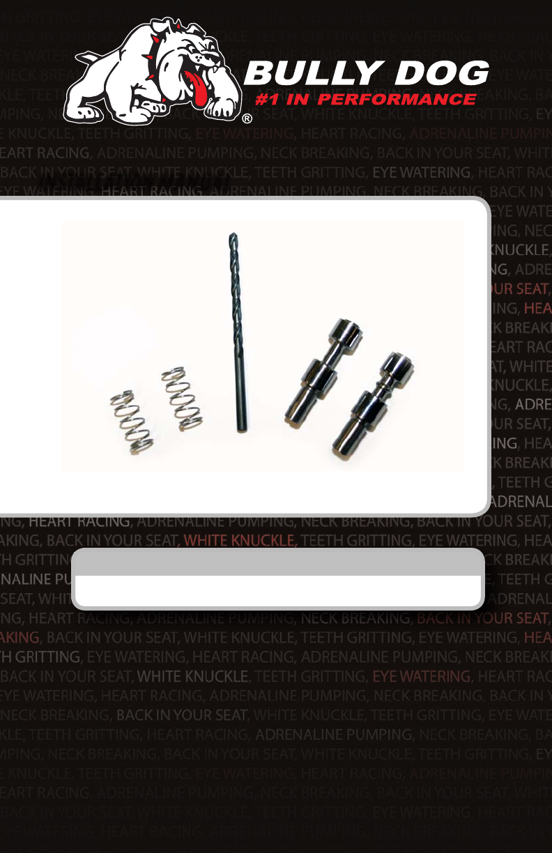
Parts included:
THE SPRINGS: The two springs included with this kit will replace two of the stock springs that are in the trans-
mission valve body.
TRIM VALVE A W/RIB: This trim valve
will replace the stock vavle. Trim Valve A is
unique, notice that it has a little rib in the
center. It is very important not to mix up Trim
Valve A with Trim Valve B.
TRIM VALVE B: This trim valve does not
have an ribs.
1/8” DRILL BIT: This is a standard o the shelf metal drill bit, you can replace it with a drill bit from a local
hardware store or from your own collection if it is lost.
Parts
THE MODULE BOX
Contents:
• Yellow Springs (2)
• Trim Valve A w/rib
• Trim Valve B
• 1/8” Drill Dit
Trim Valve A w/rib
Trim Valve B
3
REmOvINg ThE TRANmISSION vALvE BODy
Important: When dismantling the valve body be careful to store all of the parts in a safe place to prevent them
from being lost. It is also very important to keep all the parts clean.
1. Remove the tranmission pan plug and drain all the transmission oil from the pan.
2. Remove the tranmission oil lter.
3. Un-bolt the valve body from the transmission and remove it from the vehicle.
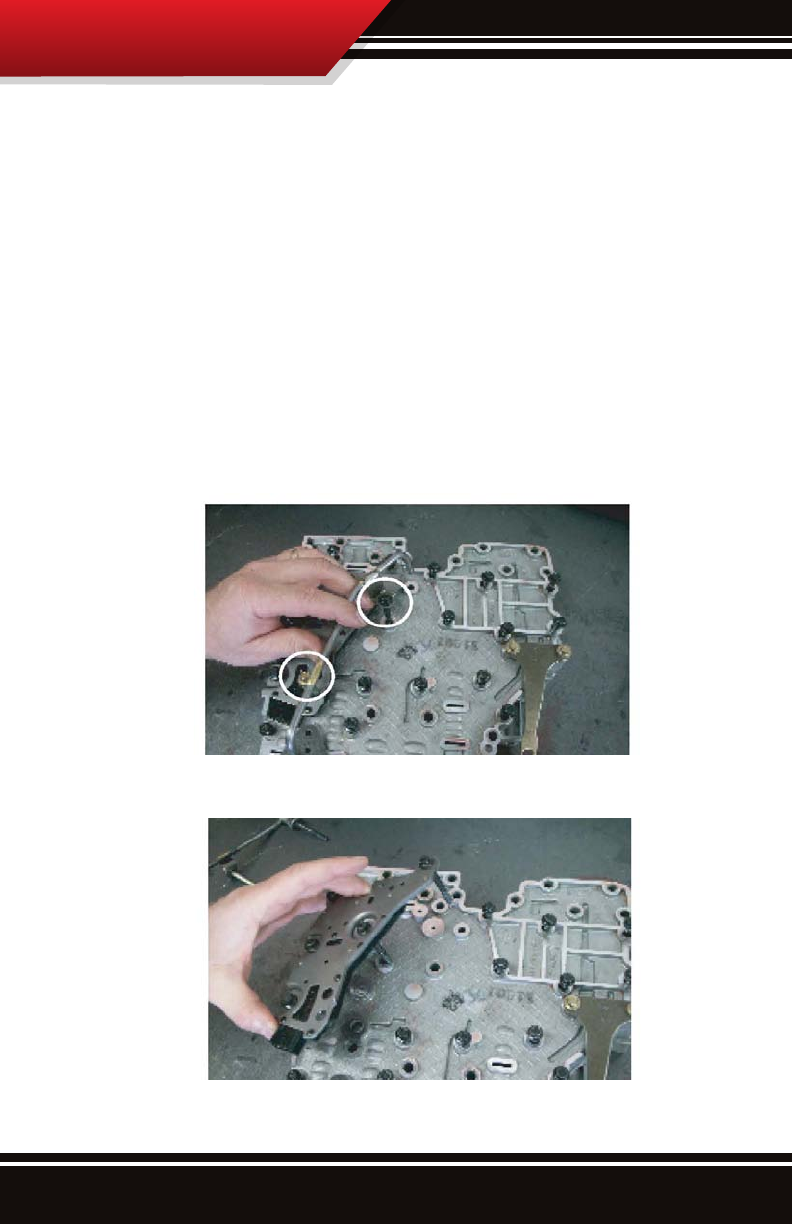
4. Remove the two bolts and remove the pipe shown in picture #1
5. Remove the plate shown in picture #2.
Removing Valve Body
PICTURE 1
PICTURE 2

4
6. Remove the plate that secures the solenoids shown in picture #3.
7. Remove all the remaining bolts that hold the valve body together and dismantle it. When separating the valve
body pull evenly on each side being carefull not to break the attaching dowles. Do not use any pry bars or tools
to separate the valve body.
8. You now have the valve body completely dismantled and are ready to start the modications. See the steps
and diagrams in the next section for details.
Removing Valve Body
PICTURE 3
PICTURE 4

5
Changing Valves
vALvE BODy mODIFICATIONS
There are two major modications, the rst is to swap out the trim valves and place springs in front of the trim
valves before replacing them. It is a good idea to rst full swap out the A Trim side and replace it before starting
on the B Trim side to reduce the chance of loosing parts or mixing things up. The second is to drill out two holes
in the separtor plate to supply more oil.
1. Remove the A Trim solenoid and the 2 valves and 2 springs.
2. Replace the parts in the order shown in the Trim Valve Diagram using the Bully Dog A Trim valve. The A Trim
valve is the valve with the rib.
3. Remove the B Trim solenoid and the 2 valves and springs.
4. Replace the parts in the order shown in the Trim Valve Diagram using the Bully Dog B Trim valve. The B Trim
valve is the valve without the rib.
TRIm vALvE DIAgRAm
6
Changing Vavles
VALVE BODY ASSEMBLY: When bolting the
valve body back up to the transmission, torque all
the bolts to 8 ft/lbs.
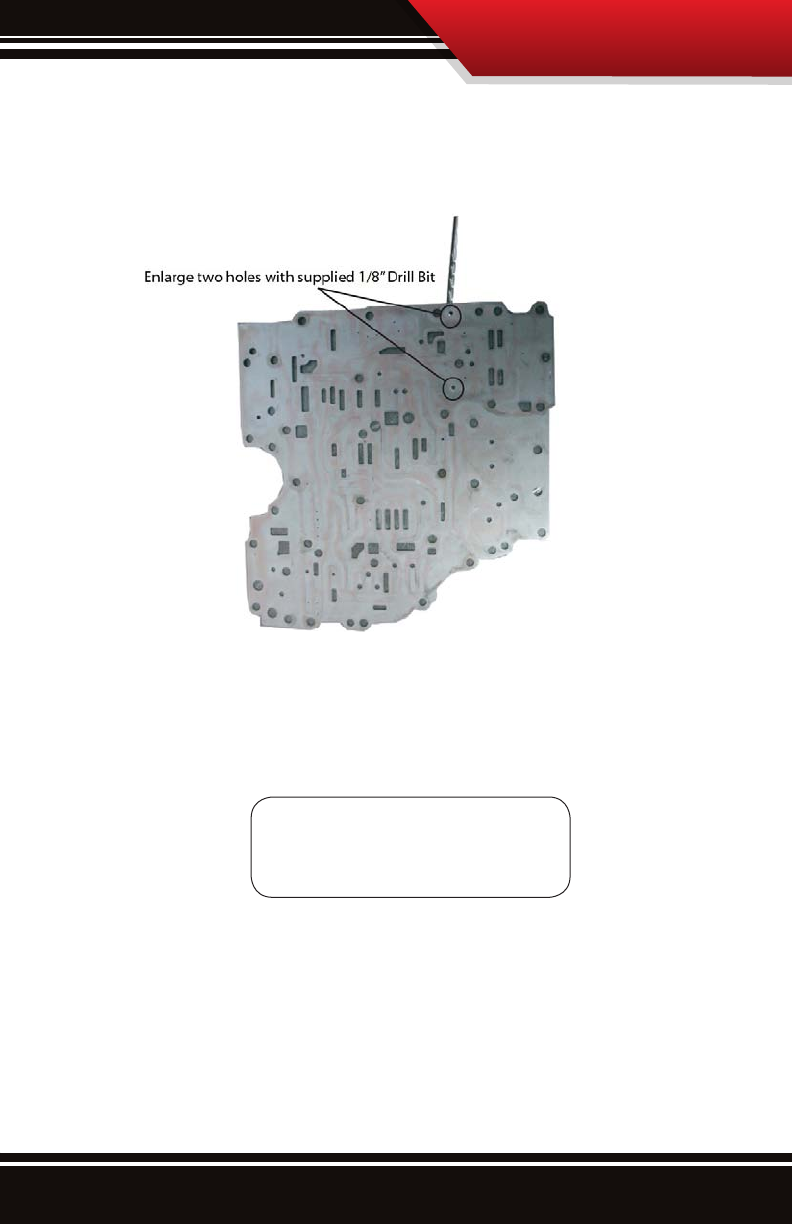
6.See the Separator Plate Drilling diagram to see where to drill out the two holes, then use the 1/8th drill bit that
is included with the kit to drill out those two holes.
7. Finally reassemble the valve body and then install back onto the transmission. Torque the bolts that connect
the valve body to the transmission to 8 ft/lbs.
SEPARATOR PLATE DRILLINg DIAgRAm
Free Technical Support at:
866-bullydog (866-285-5936)
See More at: bullydog.com
®
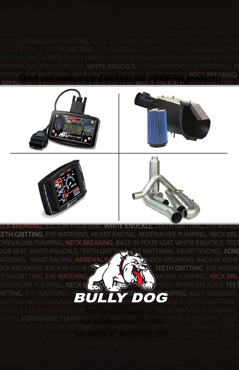
Check out more of our ADRENALINE PUMPING products!
Doc.# 153001-99 V1.0
Intake Systems
Exhaust SystemsTriple Dog GT
Downloaders
