Burnham Pf 5 Series Brochure
2015-06-08
: Burnham Burnham-Pf-5-Series-Brochure-738050 burnham-pf-5-series-brochure-738050 burnham pdf
Open the PDF directly: View PDF ![]() .
.
Page Count: 8
I-IYDRON
IC
CAST
I
RON
H EAT
OIL CASORCOI4BINATION
UBurnharri
AMERICAS BOILER
COMPANY
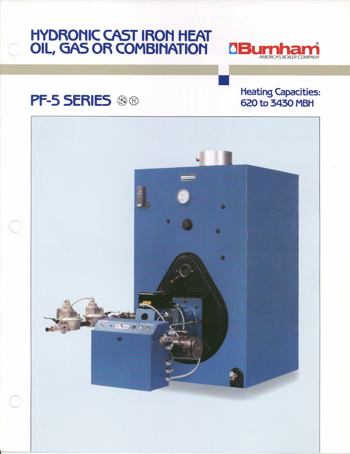
PF-5
5ER|E5
@o Heating
Gpacities:
6ZOto
545O
t-4BH
PF5 sERIEs
HOTWATER
ORSTEA[.4
BOILER
Maximum Water Working Pressur€: rc PSFWater;
15 P5l-Steam
The finest
in farge
cast iron
boiler design.
Utilizing a completely
sealed,
forced draft wet base
design, the
Burnhamo PF-5 Series
requires
no
separate base or combustion chamber.
The sealed,
forced draftdesign provides
optimum draft for controlled combus-
tion, eliminating the need for high chim-
neys or mechanical equipment
to artificial$ induce
proper draft.
The sectional
construction of the
PF-5 Series
makes it ideal
for use
in
installations where the
boiler room is
not easily accessible due
to structural
limitations. In addition to being
shipped
as individual sections the
boiler is available
with factorv-assem-
bled sections
or as a comptetely
pack-
aged unit. The
packaged
unit is
fastened to a steel skid to facilitate lift-
ingwith a fork truck or crane.
The skid
can serve as
the boiler foundation,
replacing the need
for a concrete
pad.
A
factory fire-test is available on all pack-
aged
units.
Available
in eighteen sizes
start-
ing at Gross Outputs
of 620
MBH, the
PF-5
Series
frres
gas,
oil or gas/oil com-
bination and can be equipped with
either steam
or water trim and controls.
The
product
is energy
efficient
with a combustion
efflciency of up to
82o/o.
All sizes exceed the efficiency
requirements of ASHRAE 90.1.
Quality
breeds
SecuritY
Each
PF-5 boiler section
is
hydrostatically
tested
at
two and
one
half times
ratedworking
pressure
to
make sure
thatthe
section
is
flawless.
Factory-assembled
sections
are tested
at one and
one
half times
the
rated
working
pressure.
The sections
are
surface
ground
to
insure
smooth
surface mating,
and sealed
gas-tight
with an elastic
sealing compound.
This
sealant
is
used
on
all section
joints
to
guarantee
a completely
sealed and
gas-
tight assembly
required
for forced draft
operation.
The sealant
is easily applied
and takes
less time than
applying
conventional
gasket
materials
and
lasts
many
times
longer.
Each section is then
joined
with
quality
cast
iron nipples which will
increase
the
longevity
of the
boiler by
resisting
petroleum
based
chemicals,
including
antifreeze
which can deteriorate the
gaskets
used
in some competitor's boilers.
Time-
proven
cast iron nipples last the
life of
the boiler. They expand and contract
along with the sections
they
join
ensuring the integrity of the entire sec-
tion assembly.
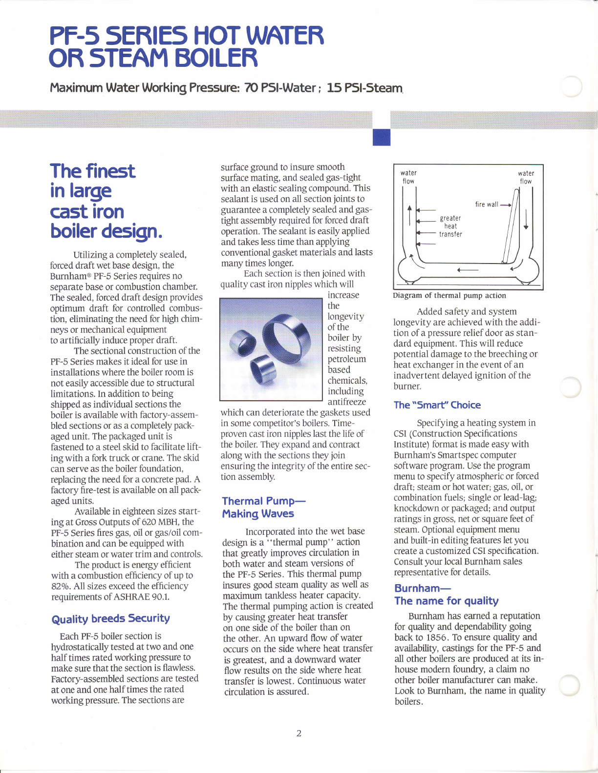
Thermal Pump-
Making Waves
Incorporated
into the
wet base
desrgn
is a "thermal
pump" action
that greatly improves
circulation
in
both
water
and
steam
versions
of
the
PF-S Series.
This thermal
pumP
insures
good
steam
qualify
as
well as
maximum
tankless
heater capacity.
The thermal
pumping action
is created
by caming greater heat transfer
on one
side
of the
boiler
than on
the
other.
An upward
flow of water
occurs
on the
side
where
heat
transfer
is
greatest,
and
a downward
water
flow results on the side
where
heat
transfer
is lowest.
Continuous
water
circulation
is assured.
water water
flow flow
fire
wall
greate
r
heat
tra nsfe r
Diagram
of thermal
pump
action
Added
safety and system
longevity are achieved
with the
addi-
tion of a pressure
relief
door as stan-
dard equipment.
This will reduce
potential
damage to the
breeching or
heat
exchanger
in the event ofan
inadvertent
delayed
ignition of the
burner.
The "Smarf'Choice
Specifying a heating system
in
CSI
(Construction
Specifrcations
Institute) format is made easy with
Burnham's Smartspec computer
software
program.
Use the program
menu to specify atmospheric or forced
draft; steam or
hotwater; gas,
oil, or
combination
fuels;
single
or leadJag;
knockdown or packaged;
and output
ratings in gross,
net
or square
feet of
steam. Optional equipment
menu
and
built-in editing
features
letyou
create a customized
CSI specification.
Consult
your local Burnham sales
representative
for details.
Burnham-
The name for
quality
Burnham
has earned a reputation
for quality
and dependabiliry
going
back to 1856.
To ensure
quality
and
availability,
castings
for the PF-5
and
all other boilers
are
produced
at its in-
house modern foundry, a claim
no
other boiler
manufacturer can
make.
Look to Burnham, the name
in quality
boilers.
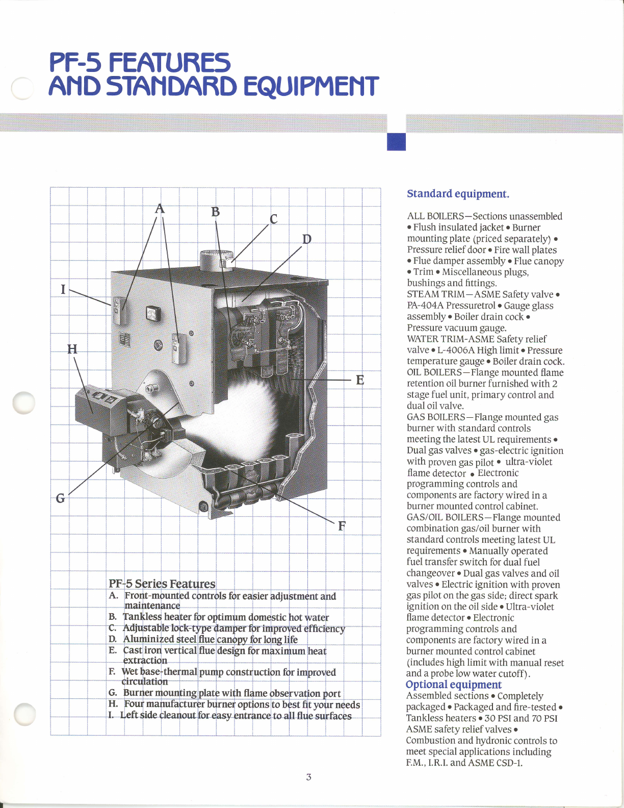
PF-5
FEATURES
AN D
sTAN DARD EQU|
P[,4ENT
F,q*b,1$$€u1.*e,+r1
ffii€ffitrfffffE$ffEi$il*fitti$ffFigi#fffi
$f+ififff
jff$i1 iff
trffi ff
Eil$#iEi+trffi
ffi
ffi
EE$€$$$fl$$E$gssff$$,F,FF
iI
, 1"/, 1, I i I i I
--t-1,*1-.rP-
'-1 r l
Standard
equipment.
ALL BOILERS
- Sections
unassembled
o
Flush insulated jacketo Burner
mounting
plate (priced
separately)
o
Pressure
relief
door
r Fire
wall plates
o
Flue
damper
assembly
o
Flue
canopy
o
Trim o
Miscellaneous
plugs,
bushings
and fittings.
STEAM
TRIM-ASME Safety valve .
P{-4}4LPressuretrol o Gauge
glass
assembly
o
Boiler
drain
cock.
Pressure
vacuum
gauge.
WATER
TRIM-ASME Safety relief
valve oL-4O06AHigh limit o
Pressure
temperature gauge
o
Boiler
drain cock.
OIL
BOILERS-Flange mounted
flame
retention
oil burner furnished with2
stage fuel unit, primary control
and
dual
oil valve.
GAS BOILERS-Flange
mounted gas
burner
with standard
controls
meeting
the latest
UL requirements
o
Dual
gas
valves. gas-electric
ignition
with proven
gas pilot o ultra-violet
flame detector o Electronic
programming
controls
and
components
are factory wired in a
burner mounted
control
cabinet.
GAS/OL BOILERS
-Flange mounted
combination
gas/oil burner with
standard
controls
meeting latest
UL
requirements
o
Manually
operated
fuel transfer
switch for dual fuel
changeover
o
Dual
gas
valves
and oil
valves
o
Electric
ignition with proven
gas
pilot on the
gas
side; direct
spark
ignition on the
oil side
o
Ultra-violet
flame detector
o
Electronic
programming
controls
and
components
are factory wired in a
burner
mounted
control
cabinet
(includes
high limitwith manual
reset
and a
probe
low water cutoffl.
Optional
equipment
Assembled
sections
. Completely
packaged
o
Packaged
and fire-tested
r
Tankless
heaters
o
30 PSI
and 70
PSI
ASME safety relief valves o
Combustion
and hydronic controls to
meet
special
applications
including
F.M..
I.R.I.
and ASME
CSD-I.
ti
+-l-
r
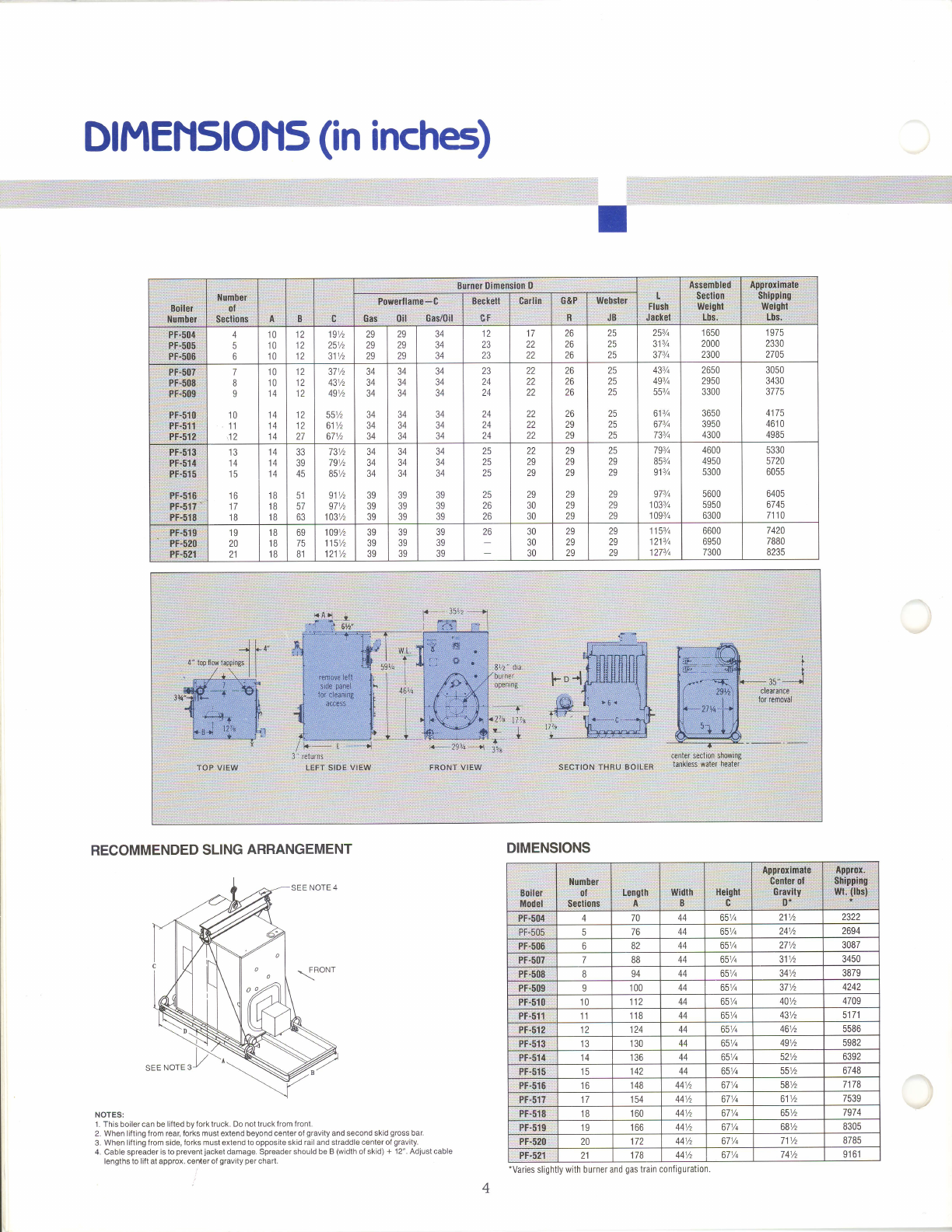
DfMENSIONS
(in
inches)
RECOMMENDED
SLING
ARRANGEMENT
I
DIMENSIONS
gi
:::i,i l, ro*e{iame: 0 ,ff
:",R:;i
,qr:soc
I
",
Pr-51t5_
pF-50s:
A
5
6
10
10
10
12
1n
12
19Vz
251/z
311/z
29
29
29
29
29
29
34
34
34
1n
23
23
17
22
22
26
26
26
25
25
25
253/q
313/q
373/4
1 650
2000
2300
1
975
2330
2705
7
B
I
10
11
,12
10
10
14
14
14
14
12
1'
IL
tt
12
27
37Vz
431/z
49Vz
551/z
611/z
67Vz
34
34
34
34
34
34
34
34
34
34
34
34
34
34
34
34
34
34
23
24
24
24
24
24
22
22
22
22
22
22
26
26
26
26
29
29
25
25
25
25
25
25
43s/a
49s/q
55Tc
613/q
673/t
733/+
26s0
2950
3300
3650
3950
4300
3050
3430
3775
4175
461
0
4985
ptlols".i
'Flfli
,ilffi
13
14
15
to
17
18
A
A
A
B
B
B
33
39
45
51
57
63
731/z
79Vz
BSVz
911/z
971/z
1031/z
34
34
34
39
39
39
34
34
34
39
39
39
34
34
34
39
39
39
25
25
25
25
26
26
22
29
29
29
30
30
29
2S
2S
29
29
29
25
29
29
29
29
29
793/q
853/a
913/q
973/4
1033/q
1093/4
4600
4950
5300
5600
5950
6300
5330
5720
6055
6405
6745
7110
19
20
21
18
1B
18
69
75
B1
1091/z
1151/z
1211/z
39
39
39
39
39
39
39
39
39
26 30
30
30
29
29
29
29
29
29
115s/q
1213/q
1273/q
6600
6950
7300
7420
7880
8235
PF-5$4 470 44 65Vc 211/z 2322
PF 50s
,576 44 651/q 241/z 2694
PF:506 :682 44 651/q 271/z 3087
PF:5{l?. 7 BB 44 651/q 311/z 3450
PF-508 B94 44 651/q 341/z 3879
Pf-509 I00 44 651/t 371/z 4242
PF51O 10 244 65Va 401/z 4709
PF-511: 11 1B 44 651/q 431/z 51
71
pF-sre. ta 24 44 65Va 46Vz 5586
PF-51
3IJ 30 44 651/q 491/z 5982
PF.514 r 14 44 65Vc 521/z 6392
PF-515 tc 42 44 651/n 551/z 6748
Pf-s16' to 48 441/z 67Vq 58Vz 7178
pr-sI? 17 54 44Vz 671/c o t'/2 7539
PF.F1$ 18 60 441/z 671/q 651/z 797
4
PF-51S 19 66 441/z 671/q 681/z 8305
PF:5?{l 20 441/z 671/t 711/z 8785
Pf-521 21 7B 441/z 671/q 7 41/z 91 61
-Varies
slightly
with burner and
gas
train configuratton
NOTES:
1. This boiler can
be li{ted by fork truck. Do not truck
from front.
2. When
lifting from rear, forks must extend beyond center of
gravity
and second skid
gross
bar.
3. When lifting
from
side,
{orks must extend to opposite skid
rail and straddle center of
gravity.
4. Cable spreader
is to
prevent
jacket
damage. Spreader should
be B
(width
of skid)
+ 12". Adjust cable
lengths to
lift
at approx.
center of
gravity per
chart.
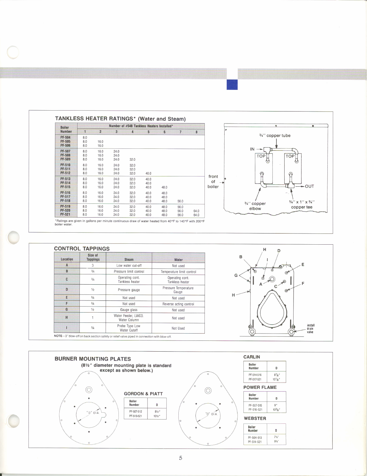
TANKLESS
HEATER
RATINGS.
(Water
and Steam)
i lit li! i!!l:!!
lli!! !l ill !i:l
:1{111 1:::: t:: u
..FflW:;:-r
]9@ffi::
;Hu"rnbei
d"
6as
tantd;is
ttq4q9
tnsdred:
.6.l
$..
i
'4r
:s*
;15:l tt 8.:
iegiffil{iill:
*,f;fgffi;::t;:
i#F".ffiff;
8.0
8.0 16.0
8.0 16.0
3r:ri#f,.+ffie.:i
:Jii;iRF.;ffiii:.1
88",l$1fl,-ry;E;
eilf"r-
B?i.hi:i
;E::rFF;g;l, i:t;;r
I'li.FiF.F.i.€fif.ec
8.0
8.0
8.0
8.0
8.0
8.0
16.0 24.0
16.0 24.0
16.0 24.0 32.0
16.0 24.0 32.0
16.0 24.0 32.0
16,0 24.0 32.0 40,0
iE;:€
sBt#l
i$,f.##
ieiP;.€rF#
iF;##iHiF-:
ii'i.ii:?.F;$*$.i:
iii?"f#ilil+
8.0 16.0 24.0 32.0 40.0
8.0 16.0 24.0 32.0 40.0
8.0 16.0 24,0 32.0 40.0 48.0
8.0 16.0 24.0 32.0 40.0 48.0
8.0 16.0 24.0 32.0 40.0 48.0
8.0 16.0 24.0 32.0 40.0 48.0 56.0
ii:i:3f;"F3$;
3:iffi$As.:
',iiirf,,f;FB-lli
8.0 16.0 24.0 32.0 40.0 48.0 56.0
8.0 .16.0 24.0 32.0 40.0 48.0 56.0 64.0
8.0 16.0 24.0 32.0 40.0 48.0 56.0 64.0
front
of
boiler
'Ratings are
gjven
in
gallons per minute
conlinuous
draw of water heated from 40oF
to 140oF with 200.F
boiler water.
7a"
copper tube
+ouT
/
/
s/a"
copper
elbow
3/c"
x1" x3/c"
copper tee
CONTROL
TAPPINGS
ia$R$,##ir
lil#fS3.l
:E; ;.lffidil,i
::;;;R:;] 3Low water cut-ofl Not
used
irii:-!li:#ri 3/t Pressure
limit
control Temperature
limit
control
;c 3h Operating cont.
Tankless heater 0perating
cont.
Tankless
heater
Vz Pressure
gauge Pressure
Temperature
Gauge
E;ir:; 3h Not
used Not used
i,Fii,,: 3h Not
used Reverse
acting
control
h: Yz Gauge
glass Not used
1Water Feeder,
LWC0.
Water
Column Not
used
3A Probe
Type Low
Water
Cutoff Not Used
:l:l+
NOTE-3" blow-off on back section safely or relief valve piped in connection with blow-olf
CARLIN
F----, t---l
lilumberlDl
f--------- -------l
I PF-514-516
1 a7h" I
I PF-517-s21
| 101/8',
I
POWER FLAME
t r.*-T---l
lHumter I o I
Fr--rr-u'u f---t-l
I PF-516-52r
| 103/8"
I
WEBSTER
fr'* [ '-_]
lr{umber ] 0 l
T____ ______t
I PF-504-513
| lvi' I
I PF514-s21
| e%" I
BURNER
MOUNTING
PLATES
(8V2" diameter mounting plate is standard
except as shown below.)
GORDON
& PIATT
5
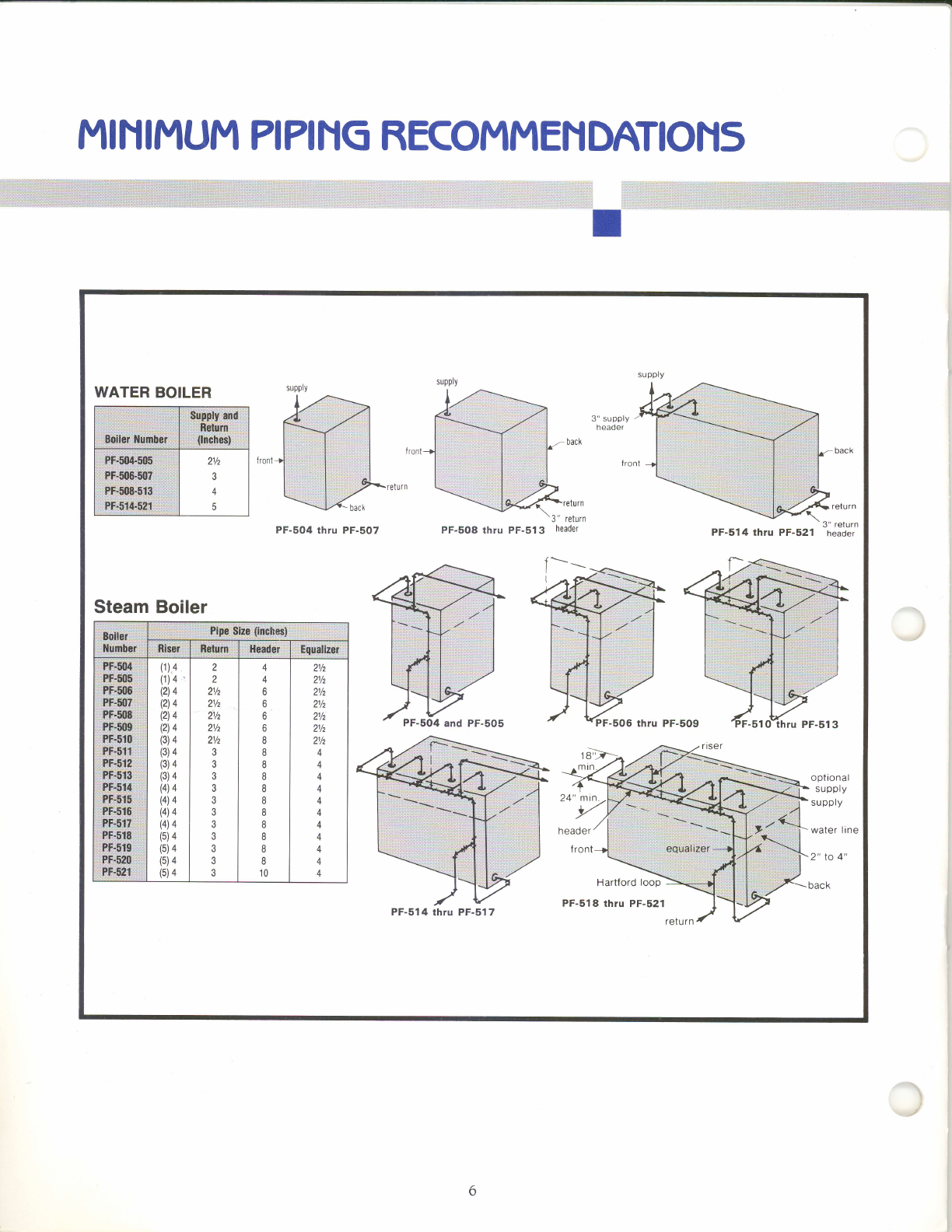
MI
N II4UM
?I?ING
RECOMMEN
DATIONs
I
suppry
supply
WATER
BOILER
3" supply
neaoer
turn
PF-504 thru PF-5O7 PF-508 thru PF-513 3
" return
header
I--
-5OO
thru PF-509
oplronal
supply
su
pply
water ltne
2" to
4"
back
ZVz
5
Steam Boiler
Pinc
$iii iinc*mt
:"detum
(1)
4
(1)
4
(2)
4
(2)
4
(2)
4
(2)
4
(3)
4
(3)
4
(3)4
(3)
4
(4)
4
(4)
4
(4)
4
(4)4
(5)
4
(5)
4
(5)
4
(5)4
z
z
2Vz
zf2
21/z
21/z
2Vz
3
4
4
6
6
6
o
8
8
8
8
8
8
I
8
I
8
I
10
21/z
21/z
zv2
ZVz
21/z
ZVz
21/z
A
4
+
4
4
A
+
4
I
t\
-+
:] !: ::
:]]i
::::
j'/
18't
mtn
24" min
PF-514 thru PF-517
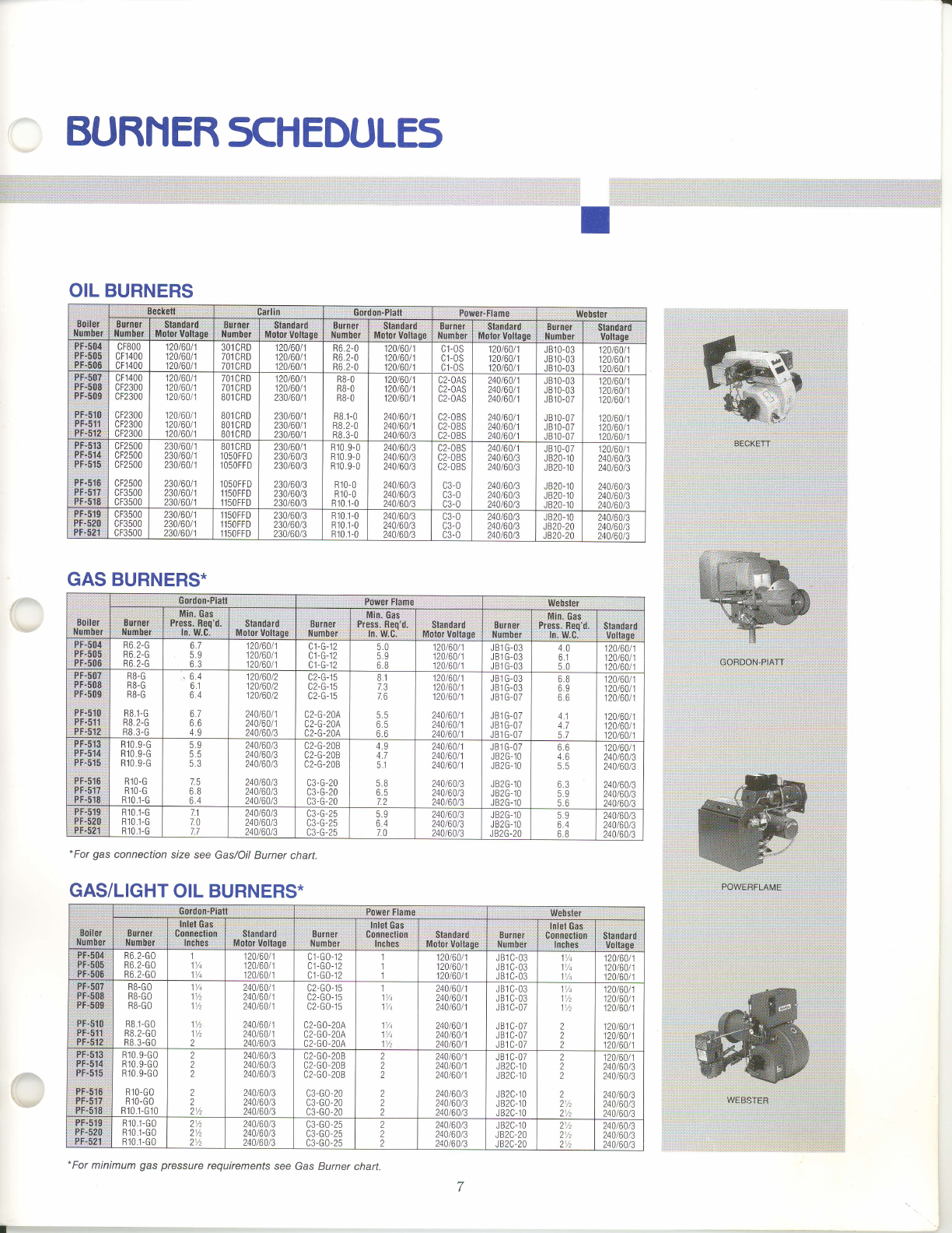
BURNERSCHEDULES
lr t:r !:1 !
laat:a:
i: tt !t :t:l
*For gas connection sLe see Gas/Oil
Burner chart.
GAS/LIGHT
OIL
BURNERS*
.;a;:::;::t,:!a;:.1
:: :r!:': ir ::
!: : :j :
a,:::la.!a'a'.,::
OIL BURNERS
Seckotl : Carttn Gordon-PlaJt PbwerlFlamq Webster
,
,;Bltr,ng-ri
lllumEtf :;:B,iiiiiei:
:i
Llutfibst: i i iElandairfi.r:
{tlBl6t xr$R*d$ :; Bt$it]t:t:"
,:m#:b-gr:
ii:i$lmdaiC:-:
:!tr6t*B$,sllara:
. Bllti:rufi:
:N3iliESt: $tandafS
Motrr voftage
li$iiiet;'
::lIwEbafi.
:iBr.* gil.:,
ilE€a;'
,#,F:;ffi*ir
CFBOO
cF1400
cF1400
20t60t1
20160t1
20t60/1
301
CRD
701
CRD
701
CRD
20t60t
20t60t
20t60t
R6.2-0
R6.2-0
R6
2-0
120t60t1
120t60t1
120t60t1
Cl.OS
c1-0s
C1-OS
120t60/1
120t60t1
120t60t1
JB10-03
JB10-03
JB10-03
120t60t
120t60t
120t60t
cF1400
cF2300
cF2300
cF2300
cF2300
cF2300
120/60t1
120160t1
120t60t1
120t60t1
120/60t1
120/60t1
701
CRD
701
CRD
BO1 CRD
BO1 CRD
BO1 CRD
BOl CRD
120t60t
120t60t
230160t
230t60t
230t60/
230t601
RB-O
RB.O
RB-O
RB.1-0
RB.2-0
RB.3-0
120t6011
120t6011
120t60t1
24016011
240t6011
240t60/3
C2-OAS
C2-OAS
c2-0AS
c2-0BS
c2-0BS
C2.OBS
240160t1
240t60/1
240t6011
240t6011
240t60t1
240t60t1
J 810-03
J 810-03
JB10-07
J 810-07
J 810-07
J 810-07
120t60t1
120t60t1
120/60t1
120160/1
120t6011
120t6011
rP.'f;:r.Et:l'Sl
.Ff!5ii4:
iEI;919;
:f F,51€
?fr.t17.
im,*$.f$i
cF2500
cF2500
cF2500
cF2500
cF3500
cF3500
230t60t1
230t60t1
23016011
230t6011
230/60t1
230t60t1
BO1
CRD
l05OFFD
lOSOFFD
lO5OFFD
115OFFD
1150FFD
230/6011
230160t3
230/60t3
230t60/3
230t6013
230/60t3
R10
9-0
R 10.9-
0
R 10.9-
0
R 10-0
R 10-0
R10.1-0
240t6013
240/60t3
24016013
240t60t3
240t60/3
240t60t3
C2-OBS
C2.OBS
c2-0BS
c3-0
c3-0
c3-0
240160t1
240t60t3
240t60t3
240t6013
240t6013
240/60t3
JB10-07
JB20-10
J B20-10
JB20-10
JB20-10
J820-10
120t6011
240160t3
240t60t3
240t6013
240t60t3
240/60t3
Fof.l.{tl*,
PF-520
PF-521
cF3500
cF3500
cF3500
230t60/
230/60/
230/60t
50FFD
5OFFD
5OFFD
230160t3
230t60/3
230t6013
R10
1-0
R10 1-0
R10.1-0
240/60t3
240160t3
240t60t3
c3-0
c3-0
c3-0
240160t3
24016013
240t60t3
J
820-10
lB20-20
JB20-20
240t60/3
240t6013
240t6013
GAS BURNERS*
Gordon:Ptatt: ,,
F,*r't FlafiP: ::llllGbster
::Brtirlci:
illlur*tsl
1::'$i6;$P3.:.
:FilSs:R:c4d;
't ::lllr
:1{;0::
: : ,i.:$lgn#r.d
: :
,
:,lff*lor'Vol{5gB:
:,gUl-n€r,;
.lhfuiitdr:=
::,MltliG-a$::i;
F1lt$*,;Fb"qrd":
:,
ln;:lff e;:: i:
R6.2-G
R6.2-G
R6.2-G
6.7
5.9
6.3
20/60/1
20/6011
20160t1
Ul-tr-lZ
u t-u- tz
u t-u- tz
50
5.9
6B
120160t1
120160t1
120160/1
JB
JB
JB
G-03
G-03
G-03
4.0
o.l
5.0
120t60t
120t60t
120/60t
;*Fi3.fi;
iS:F.S{#
'x,Fg99'9j
19f:'5t8
:PF:,Sif.Ii
?F.5,1t*
R8-G
R8.G
R8-G
RB..1.G
R8.2-G
RB.3.G
,6.4
o. I
6.4
6.7
6.6
4.9
120t60t2
120160t2
120t60t2
240/60t1
240t60t1
240t60t3
c2-G-15
c2-G-1s
c2-G-15
c2-c-20A
c2-G-20A
c2-G-20A
8.1
7.3
7.6
q5
65
6.6
120t6011
120t60t1
120t60t1
240t60t1
240t60t1
240t60t1
JB1 G.03
JB] G.03
JBl G-07
JBl G.Oi
JBl
G-07
JBl G-07
6.8
69
66
4.1
4.7
5.7
120t60t
120t60/
120t60t
120t60t
120t60t
120t60t
Ffir:.f.
:Pf.,'558;i
ffiE
iptF;rs-.t6:
.flFr*f?:.:
,F#5|fi:
R10.9-G
R10.9-G
R10.9-G
R1O-G
R1O-G
R10.1-G
5.9
55
5.3
7.5
6.8
o.4
240t60t3
240/6013
240160t3
240160t3
240t60t3
240t60t3
c2-G-208
c2-G-208
c2-G-208
c3-G-20
c3-G-20
c3-G-20
4.9
51
5.8
6.5
72
240t6011
240t6011
240t60t1
240t60t3
240t60t3
24016013
JB1 G-07
J B2G-10
J B2G-10
J B2G-10
JB2G-10
JB2G-10
66
4. Cl
5.5
63
59
56
120160/1
24016013
240160t3
240t60t3
240t60t3
24016013
,F,f'$?{.
::B'1[.i$l$.'
:FF';' li
R10 1-G
R10..1-G
R10.1-G
71
7.0
7.7
24016013
240t6013
240t60t3
c3-G-25
c3-G-25
c3-G-25
5.9
64
7.0
240t6013
24016013
240160t3
JB2G-10
JB2G-10
JB2G-20
59
6.4
6B
240t60t3
240t60t3
240t60t3
.. Qoilrit.
r
i
:HEnbei l
iF.b,$raliFlsfie :
'$/,*bslcti
:B,i!*nrEr
it
,llnfabefi:
;:t|!RffSd,$':
:€ohntcliolt
:.:tnbfi
.$;:
!;
,l0lE!:Gaii:,
0ongsrli0r*:'
::lfitfild$j;;.
::ita::,::r:,!::
;5,165d.6id:
::tf hgG
:
P.F'5ffi:t
PF:606, l
Fp:$d6,i
R6.2-G0
R6.2-G0
R6.2-G0
)/c
1/q
120t60t
120t60t
120t60t
c1
-G0-12
c1-G0-12
c1-G0-12
120t60t
120t60t
120160t
JBl C-03
JBl C-03
JB1 C.O3
1Yq
11/t
11/a
120t60t
120t60t
120t60t
Ft';5tF,
PF6oti
,?F,::fBF'
R8-GO
RB-GO
RB-GO
RB.1-GO
RB.2.GO
RB.3.G0
1l/q
11/z
11/z
1t/z
1t/z
2
24016011
240t60t1
240t60t1
240t60t1
240t60t1
240t60t3
c2-G0-15
c2-G0-15
c2-G0-15
c2-G0-20A
c2-G0-20A
c2-G0-20A
1
11/q
11/q
1'/q
11/t
11/z
240t60t
240t60t
240t601
240t60t
240t60t
240t60t
JB1 C-03
JB1 C-03
JB1 C.O7
JBl C-07
JBl C-07
JB1 C.07
11/c
1fz
1fz
2
2
2
20t60t
201601
20t60t
20t60t
20t60t
20t60t
iPJjfiti*
:;F 5t-+:
i,f-#6fa R10.9-G0
R10 9-G0
R10.9-G0
R10-G0
R10-G0
R10.1-G
10
2
2
2
2
2
21/z
240t60t3
240t60t3
240t60t3
240t60t3
240t60t3
240t60t3
c2-G0-208
c2-G0-208
c2-G0-208
c3-G0-20
c3-G0-20
c3-G0-20
2
2
2
2
2
2
240t60t1
240t60t1
240t6011
240t60t3
240160t3
240t6013
JB1
C-07
JB2C-10
JB2C-10
JB2C-10
J
B2C-]O
J B2C-1 O
2
2
2
2
21/z
21/z
120160t1
240t60t3
240t60t3
24016013
240t60t3
24016013
:rf,.f;.+5;19
PF-520
Pf-521'
R10
R10
R10
-G0
-G0
-G0
21/z
21/z
21/z
240160t3
240t60t3
24016013
c3-G0-25
c3-G0-25
c3-G0-25
2
2
2
240160t3
240t60t3
240t60t3
J B2C-1
O
JBZC-20
JBZC-20
21/z
21/z
2'/z
240t60t3
240160t3
240160t3
-For minimum gas pressure requirements
see Gas Burner chart.
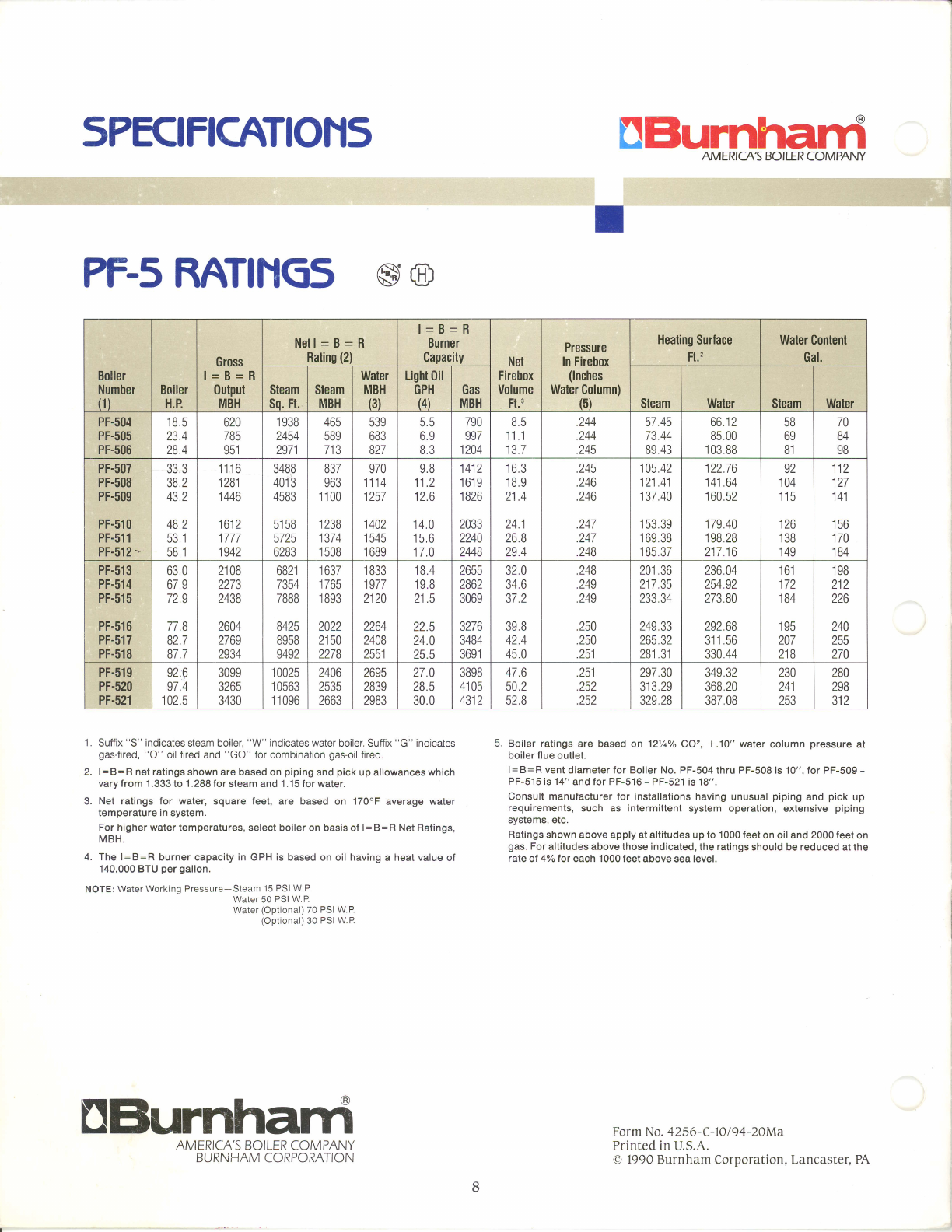
SPECIFICATION5
PF5
RATINGss@
UBurnhard
AMERICAS BOILER COMPANY
Form No. 4256-C-10
I 94-2AMa
Printed in
U.S.A.
O 1990 Burnham
Corporation, Lancaster,
PA
1 . Su'llix
"S" ndical6s sisam boil€r,
"W" ndicat€s wal€r boiler.
Sutf
x 'G" ind
cates 5. Boilgr ratings ara basad
on 12y.,k
COz,
+.10" weter colu mn pre$ur€ at
gas
fir6d,
"O" oil tircd and
''GO" for comblnalion
gas-oil
fted. boilsr llu€ outl6t.
2. t= B
=
B
n6t ralings shown ar€ bas6d on
piping
and
pick
up a owancss wh tch l=B=Av6ntdlam€leftor Boller
No.
PF-504thru
PF-508is10",for PF-509-
varytrom 1.333to 1.288 for
steam and 1.15iorwat€r. PF-515is14"andlorPF_516-PF-521ls18".
3. Net ratings for water, squaro l6€t, ar€ bassd on 170.F average water con 'sult
manulactuf€r tor Installalions
having unusual
piping
snd pick up
rem
perarure
In
system. - rsquirsm€nls, such as Inl€rmlltent
sFtem operation, €xl€nsivs piping
For hish€r wat€r r€mp.rarurss' s.rect boirsr on basis
ot r=B=R Net Rarrnss' illiil":iii" **" *rry at arritud€s up to 1oo0 r€st on ol and 2000 reer
on
MBH. gas.
For
altitudos abov€lhoss indicatsd, ihe ralings
shoutd be reduced at th€
4. Th6 |
=
B
=
R bu rnor capaclty in G PH i5 bas€d on oit hsving a heal value
ol 'ale
ol 4% lor each 1OO0 t€€t sbove
sea
t€vet.
'140,000
BTu
p€r gallon.
NOTE: WalerWor<iig
Pr€ssurs
Sl€a- 15 PSIWI-.
wal6r
50
PslwP
Water loolional)
70 PSIWP
{Oolional) 30
PslwP
UBurnhard
AMERICA'S
BOILER
COMPANY
BURNHAM CORPORATION
Boiler
Number
(1) Boiler
H.P.
Gross
l=B=R
0utpul
MBH
Netl
= B
= R
Rating
(2)
l=B=R
Burner
Capacity Net
Firebox
Volume
Ft.3
Plessure
In Firebox
(lnches
Water
Column)
(5)
Heating
Surlace
Ft., Water Content
Gal.
Steam
Sq. Ft. Steam
MBH
Waler
MBH
(3)
LighlOil
GPH
{4)
Gas
MBH Steam Water Steam Water
PF-504
PF-505
PF-506
18,5
23.4
28.4
620
785
oq1
1
938
2454
2971
4bc
589
ttJ
539
683
827
55
69
8.3
790
997
1204
85
11 1
15.I
244
244
245
57.45
73.44
89
43
66 12
85.00
103
88
58
69
81
IU
84
98
PF-507
PF-508
PF-509
PF-510
PF-511
PF-512
*
JJ.J
J6.Z
43.2
482
JJ. I
cd. I
1116
1281
1446
1612
1777
1942
3488
401
3
4583
51 58
5725
6283
837
963
1 100
1238
1374
1
508
970
111 A
| | tT
I lcl
1402
1
545
1
689
98
112
ILO
14.0
15
6
| /.u
't
Al a
t+tL
1619
1826
2033
2240
2448
to.J
18.9
o1 A
Ll,a
z+. I
26.8
29.4
245
246
246
247
aA1
L+t
248
105 42
121 41
137 40
ICJ.JY
169 38
185
37
12276
141
64
160
52
179 40
198 28
217.16
92
104
|3
126
138
149
112
127
1i4
l.+ |
tco
170
184
PF-513
PF-514
PF-515
PF-516
PF-517
PF-518
630
679
729
77.8
82.7
87,7
21
08
2273
2438
2604
2769
2934
6821
7354
7888
8425
8958
9492
1
637
tioJ
1
893
2022
2150
2278
1
833
1977
2120
2264
2408
2551
18 4
19.8
21 5
22.5
240
25.5
2655
2862
3069
3276
3484
3691
32.0
346
372
398
42.4
450
248
249
249
250
250
lJl
201
36
217
35
ZJJ.J+
249.33
265.32
281
31
236.04
254
92
273.80
292
68
J I t.JO
330
44
tot
172
184
195
207
218
198
212
226
244
255
270
PF-519
PF-520
PF-521
qzA
974
102
5
3099
3265
3430
1
0025
I USOJ
11096
2406
2535
2663
2695
2839
2983
zt.u
285
30.0
3898
41 05
+Jtt
476
502
528
251
252
252
297
30
313 29
329.28
349.32
368
20
387.08
230
itl
zt+ |
253
280
298
otz
