Burnham Sage Boiler Control Instruction Manual 1a Controller
2015-06-08
: Burnham Burnham-Sage-Boiler-Control-Instruction-Manual-738100 burnham-sage-boiler-control-instruction-manual-738100 burnham pdf
Open the PDF directly: View PDF ![]() .
.
Page Count: 56
- Instruction Manual
- Installation
- Installation
- Installation
- Installation
- Mounting & Wiring Sensors (Cont.)
- Installation
- Installation
- Coil Address
- Description
- Read/Write
- coil = 0
- coil = 1
- Notes
- 00001
- Disable
- Enable
- 00002
- Disable
- Enable
- 00003
- Local
- Remote
- 00004
- Y
- Off
- On
- 1
- 00005
- Off
- On
- 00006
- Off
- On
- 2
- 00007
- Off
- On
- 2
- 00008
- Off
- On
- 2
- 00009
- Off
- On
- 2
- 00010
- Off
- On
- 2
- 00011
- Off
- On
- 2
- 00012
- Off
- On
- 00013
- Off
- On
- 00014
- Off
- On
- 00015
- Off
- On
- 4
- 00016
- Off
- On
- 00017
- Off
- On
- 00018
- Off
- On
- 00019
- Off
- On
- 00020
- Off
- On
- 3
- 00021
- Off
- On
- 3
- 00022
- Off
- On
- 3
- 00023
- Off
- On
- 3
- 00024
- Off
- On
- 3
- 00025
- Off
- On
- 3
- 00026
- Off
- On
- 3
- 00027
- Off
- On
- 3
- 00028
- Off
- On
- 3
- 00029
- Off
- On
- 3
- 00030
- Off
- On
- 3
- 00031
- Off
- On
- 3
- Off
- 3
- Off
- 4
- Off
- 4
- Off
- 4
- Off
- 4
- Off
- 4
- Off
- 4
- Off
- 4
- Off
- 4
- Off
- 4
- Off
- 4
- Coil Address
- Description
- Read/Write
- coil = 0
- coil = 1
- Notes
- Off
- 4
- Off
- 4
- Off
- 4
- Off
- 4
- 00047
- Off
- 4
- Modbus
- Register
- Address
- Description
- Read/
- Write
- Engineering Units for Register
- = 0
- Engineering Units for Register
- = 100
- Units
- Notes
- 40001
- -50
- 300
- F
- 40002
- -50
- 300
- F
- 40003
- -50
- 300
- F
- 40004
- 60
- 230
- F
- 40005
- -50
- 300
- F
- 40006
- Y
- 0
- 100 or 300
- % or F
- 1
- 40007
- PCB Temperature Sensor
- -50
- 300
- F
- 40008
- 0
- 100
- %
- 40009
- 110
- 180
- F
- 40010
- 0
- 100
- %
- 40011
- 1
- 7
Sage Boiler Control Instruction Manual Page 1 of 56 102121-01R2 - 4/11
Sage Boiler Control
(SBC)
Instruction Manual
www.burnhamcommercialcastiron.com
Contents
Introduction
Quick Reference 2
Overview 4
Product Features
Boiler Sequence 6
Single Boiler Control Mode 9
Multiple Boiler Control Mode 10
EMS Boiler Control Mode 11
Manual Boiler Control Mode 14
Auiliary Device 15
Front Panel
Features 16
Display Mode 17
Menu Navigation 18
Setpoints Menu 19
Installation
Mounting & Wiring Sensors 20
Terminal Layout 25
External Connections 26
Communication 28
Peer-To-Peer Network 30
RS485 Modbus Network 31
Setup & Tuning
Boiler Configuration Menu 33
System Configuration Menu 34
Setup Menu 35
Manual Mode 40
Trouble Shooting
Alarm Messages 41
Diagnostics Menu 43
Sensor Resistance Chart 46
Security Menu 47
Specifications
General 48
Component Description & Repair Part Numbers 49
Appendix
A. Parameter Summary 50
B. Customer Parameter Worksheet 52
Warranty Rear Cover
Application
The Sage Boiler Control (SBC) has been designed
for commercial hot water boiler applications.
Intent
This instruction manual includes detailed functional,
installation and setup information.
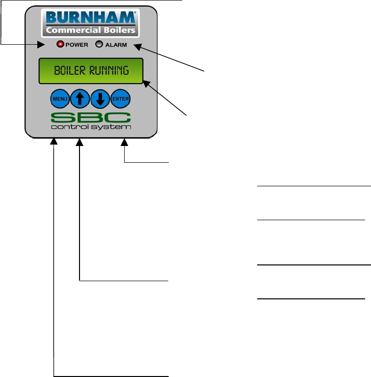
Sage Boiler Control Front Panel
(Showing Power & Alarm LEDs,
2 Line 16 Character Message Display
and 4 Pushbuttons)

Sage Boiler Control Instruction Manual Page 2 of 56
Introduction
Quick Reference
CONTROL
MODE
LCD Display
Outlet Sensor
& Local SP
Mode
Remote Sensor
& Local SP Mode
Outlet Sensor &
Remote SP
Mode
Remote Sensor
& Remote SP
Mode
Remote
Control
Mode
Manual
Mode
Energy Management System (EMS) Boiler Control
Typical
Application Single Boiler Multiple Boilers Single Boiler
Setpoint Input Multiple Boilers
Setpoint Input Modulation
Rate Input
Manual
Operation
Water Setpoint
Temperature
Sensor Boiler Outlet Remote System Boiler Outlet Remote System Ignored Ignored
Setpoint Operator Operator
Input (C+C-) or
Modbus* Input (C+C-) or
Modbus* Ignored Ignored
“On” and “Off”
Point Operator Operator Operator Operator Ignored Ignored
Outdoor Air
Reset Option Option Ignored Ignored Ignored Ignored
Domestic Hot
Water Priority
(DHWP) Option Option Ignored Ignored Ignored Ignored
Warm Weather
Shutdown
(WWSD) Option Option Option Option Option Ignored
Call For Heat
Call For Heat Based on
Setpoints Based on
Setpoints Based on
Setpoints Based on
Setpoints Input (RO) or
Modbus Manually Set
Modulation
Rate
Internal Boiler
Control Based on
Setpoint Based on
Setpoint Based on
Setpoint Based on
Setpoint Ignored Ignored
Lead Boiler
Control Peer-to-Peer
Connected With Peer-to-
Peer Connected With Peer-to-
Peer Connected With Peer-to-
Peer Connected Ignored Ignored
Remote EMS
Control Ignored Ignored Ignored Ignored
Input (C+C-)
or Modbus Ignored
Manual
Control Ignored Ignored Ignored Ignored Ignored By Operator
Remote
Connections
Local / Remote
Input (LR) Ignored Ignored Closed Closed Closed Ignored
Remote On/Off
(Enable)
Input (RO)
Enable/
Disable Enable/
Disable Enable/
Disable Enable/
Disable On/Off Ignored
Remote Control
Input (C+C-) No No
Remote
Setpoint Remote
Setpoint Remote
Modulation Ignored
Communication
Network
Peer-To-Peer
or
Modbus*
Peer-To-Peer
or
Modbus*
Peer-To-Peer
or
Modbus*
Peer-To-Peer
or
Modbus*
Modbus
Only Modbus Only
Additional
Information Page 9 Page 10 Page 11 Page 12 Page 13 Page 14
* If Modbus is selected the Peer-To-Peer Network can not be used. Modulating Lead/Lag features require the Peer-To-
Peer Network.

Sage Boiler Control Instruction Manual Page 3 of 56
Introduction
Quick Reference
Abbreviation List
Abbreviation Description
AL Flame Safeguard Alarm
BIT Boiler Inlet Temperature
BOT Boiler Outlet Temperature
BP Boiler Pump
BV Blocked Vent Switch
C Common Termination Point
CA Low Combustion Air Flow
CH Call For Heat (CFH)
CS Fuel Valve Energized
DH Domestic Hot Water Heating Demand
DP Domestic Hot Water Priority (DHWP)
SBC Sage Boiler Control
EMS Energy Management System
GP High and Low Gas Pressure Switches
HL High Limit Aquastat
HP High Pressure Gas Switch
IN Boiler Inlet Water Temperature
LC Low Water Cutoff Switch
LL Lead Lag
LO Lockout Indicator
LR Local / Remote
M Electric Motor
Mix 3 Way Mixing Valve
OA Outside Air Temperature
OL Operating Limit Aquastat
OO Burner On / Off Switch
OUT Boiler Outlet Water Temperature
RO Remote On / Off
RST Remote System Temperature
SH Space Heating Demand
SI Spare Input (Programmable)
SO Spare Output (Programmable)
SP Setpoint (As found in “Operational SP” and “Remote SP”
SP System Pump
VI Vent Inducer
WF Low Water Flow
WWSD Warm Weather Shutdown
Mixing Valve
Control, (MR, MS)
Description
Termination
Numbers
Termination Number Identification (Typical):
Sage Boiler Control Instruction Manual Page 4 of 56
Introduction
Overview
Sage Boiler Control Overview
The Sage Boiler Control (SBC) is a complete boiler monitoring and automation system. The SBC provides advanced
boiler modulation, operating control, diagnostics, multiple boiler lead-lag and auxiliary device control. The SBC provides
advanced control features in an easy to use package.
Flexible, Field Selectable Control
Control modes, water system, boiler auxiliary and
modulating lead/lag control features are menu selectable
without the need for external programmers, laptops or
down loads. Every boiler is shipped with factory defaults
that make field menu selections unnecessary unless you
are applying additional control features.
Boiler Monitoring and Diagnostic Displays
The SBC’s two line by sixteen character LCD display
may be used for monitoring boiler inlet and outlet,
remote system and outside air temperatures, modulation
rate setpoint and modulating percent and mixing valve
demand percent. Additionally, the display automatically
presents boiler sequence messages, alarms, hold and
lockout messages. A diagnostic menu is included that
provides the last 10 alarm messages and boiler inlet
temperature alarm history. Boiler inlet temperature
alarm history includes time and date, the lowest inlet
temperature reached and the amount of time the water
temperature dropped below the alarm setpoint.
Modulation Rate and On/Off Modes
The SBC may simply control boiler modulation and
on/off output based on the boiler water outlet
temperature and an operator adjusted setpoint.
However, using parameter selections, the SBC allows
the boiler modulation and on/off output to respond to
remote system water and outside air temperatures,
Domestic Hot Water Priority (DHWP) input or Energy
Management System (EMS) modulation rate demand,
remote setpoint or remote start/stop commands.
Parameter selections of remote system water
temperature and remote mode determine the choice of
one of six different control modes.
Advanced Availability
The above control modes are menu selectable options.
However, if a selected sensor fails, the SBC
automatically changes to a control mode that will allow
continued automatic operation of the boiler. For
example, in the event of a remote system temperature
sensor failure, the SBC will automatically switch to boiler
outlet temperature sensor based control.
Outdoor Air Reset
When selected the modulation rate setpoint is
automatically adjusted based on outside air temperature.
Outdoor air “reset” setpoint saves fuel by adjusting the
water temperature of a heating boiler lower as the
outside air temperature increases.
Warm Weather Shutdown (WWSD)
Some boilers are used primarily for heating buildings,
and the boilers can be automatically shutdown when the
outdoor air temperature is warm. When outside air
temperature is above the WWSD setpoint, this function
will prevent the boiler, boiler pump and/or the system
pump from starting.
Domestic Hot Water Priority (DHWP)
Some boilers are used primarily for building space
heating, but also provide heat for the domestic hot water
users. When the outdoor temperature is warm, the
outdoor reset setpoint may drop lower than a desirable
domestic hot water temperature. When enabled and a
DHWP contact input is detected, the hot water setpoint
is adjusted to be greater than a field adjustable DHWP
Setpoint.
Water Side Control Outputs
In order to maximize the life and availability of hot water
systems it may be desirable to automate mixing valves,
boiler pumps, system pumps, and standby system
pumps. The SBC makes this type of automation totally
integrated and cost effective. The control of these
devices is field selectable through simple yes/no menu
selections.
Combustion Air Side Control Outputs
Boiler room Combustion air dampers (fresh air dampers)
and Vent Inducer control outputs are field selectable
options.
Peer-To-Peer Network
The SBC includes state-of-the-art modulating lead-lag
sequencer for up to eight (8) boilers capable of auto
rotation, outdoor reset and peer-to-peer communication.
The peer-peer network is truly “plug and play”.
Communication is activated by simply connecting a
RJ11 telephone line between boilers. The SBC provides
precise boiler coordination by sequencing boilers based
on both remote system water temperature and boiler
modulation rate. For example, the lead boiler can be
configured to start a lag boiler after operating above 90%
modulation rate for longer than an adjustable time. The
boilers are modulated in “unison” (parallel) modulation
rate to ensure even heat distribution
Modbus Communication Interface
A factory configured RS485 Modbus interface is
available
for Energy Management System (EMS) or SCADA
system monitoring and control.
Sage Boiler Control Instruction Manual Page 5 of 56
Introduction
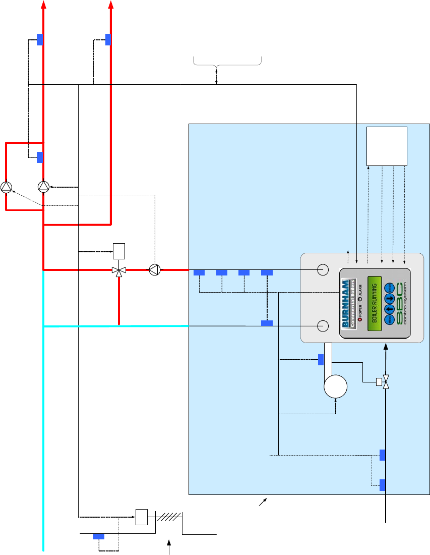
Overview
M
M
Domestic Hot
Water Override
Switch
System Pump
Feedback
Spare Output
Standby System Pump
System Pump
Boiler Pump
Mixing Valve
Control
Modutrol Motor
Control
System
Supply Water
Domestic
Hot Water
Supply
Return Water
Outside Air
Temperature
Combustion Air
Damper
Low Water Flow Switch
Low Water Cutoff Switch
Boiler Outlet TemperatureBoiler Inlet Temperature
Remote System
Temperature
High Temperature Limit
Fuel Switches
Combustion
Air Flow
Switch
Remote On / Off (Enable)
Local / Remote Switch
Lockout Indicator
Building Automation
System
Boiler On/Off
Switch
Fuel
Supply
Fresh Air
Supply
FAN
Modbus RS-485, RJ-11
Connection
Call For Heat Relay
Fuel Valve Energized
Alarm (Lockout)
Low Fire
Boiler
Jacket
Primary
Control
Sage Boiler Control
Sage Boiler Control Instruction Manual Page 6 of 56
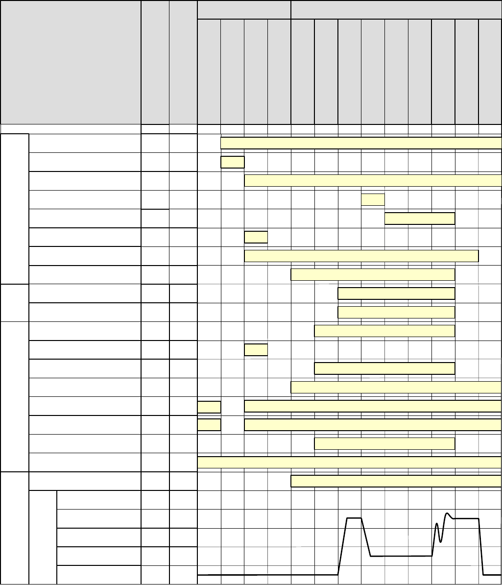
Product Features
Boiler Sequence
SI
CS
SI
CH
AL
DP
O+,O-
VI
BP
-
-
2,30
SP
25,30
70,71,
72
Outdoor Air Temp >
Warm Weather Shutdown Setpoint
-
Relay Outputs Interlock Inputs
Terminal Number
Parameter/Note
Low Fire Hold
Spare Output
Boiler Pump
System Pump
Modulation Outputs
Call For Heat Relay
Domestic Hot Water Priority
Flame Safeguard Alarm
Parameter / Notes
20,74
Limits
Inputs
9
Call For Heat
Lockout Indicator
(Manual Reset Required) LO
-
44,30,
75
Fuel Valve Energized
Recycling Limits
(LC, OO, WF, GP and HL inputs)
Pump Purge
Main Ignition
Low Fire Hold
Purge / Pilot Ignition
Low Fire / Ignition
Pump Cooldown
Boiler Running
BOILER STATE
LCD Display
System Pump Feedback
9
-
8,27,
28
-
Non-Recycling Limits
(Combustion Air Flow (CA Input))
Blower High Speed
Purge %
Modulation
Low Fire %
Blower 0 Volts
V+,V-,
P+,P - 49
52
-
9,51/f
50
R+,R-
OR
BO,BC
SO
10
System Pump Backup Pump
SO
10,27/
e
Combustion Air Damper
SO
10
System Alarm
LC , OO ,WF,
GP,HL
CA
Mixing Valve Output
MS,MR 6,79,
80
Firing Rate
Boiler Disable
RO
Boiler Disable or Remote On/Off
-
-3/d - - -53 4/d
Spare Output On
Call For Heat Relay On
Recycling Limits Made
Call For Heat
Non-Recycling Limits Made
-
Warm Weather
Shutdown
Standby
Lockout
Limit Hold
Combustion Air Damper Open
V+,V-,
P+,P -
V+,V-,
P+,P -
V+,V-,
P+,P -
V+,V-,
P+,P -
b &ca aa
Fan Post Purge
54/d
Boiler Pump On
Domestic Hot Water Demand Monitored
System Pump On
System Pump Feedback Monitored
Starts in response to System Pump Feedback Input SI
Alarm Status is Monitored
Modulate
Boiler Enable/Disable On
Start/Stop Sequence StatesPre-Sequence States
Notes
a. Boiler Pump is “On” when the Boiler Pump is set to “On Always” or the boiler is lead boiler and Boiler Pump is set to “On Lead”
b. Boiler Pump is "On" when the Boiler Pump is set to "On Always" and WWSD is set to "WWSD of System Pump" or “Off”
c. System Pump is "On" when the System Pump is set to “yes” and WWSD is set to either "WWSD of Boiler" or "Off"
d. Boiler pump is "On" during Prepurge and Post Purge when Boiler Pump is set to "Purge" or boiler is lead & Boiler Pump is set to “On Lead”
e. Combustion Air Damper Spare Output is maintained “On” for 2 minutes after the Call For Heat is removed.
f. Modulation rate is held at purge % when low fire input is not provided.
Sage Boiler Control Instruction Manual Page 7 of 56
Product Features
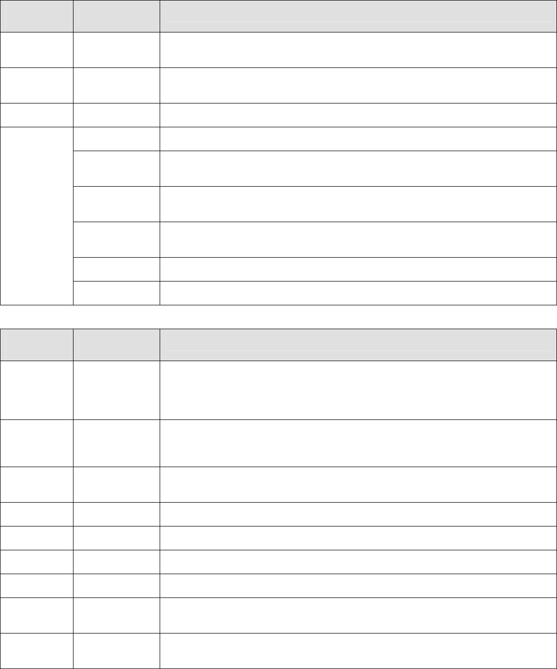
Boiler Sequence (Continued)
Pre-Sequence States
BOILER
STATE
LCD Display
CONTROL MODE
LCD Display Description
Boiler
Disabled
Any Mode
(Except for
Remote Control)
Boiler is prevented from starting; Remote On/Off (Enable) (Terminal RO) Input is not
energized.
Warm
Weather
Shutdown
Any Mode
(Except for
Manual Mode)
Boiler is prevented from starting, Warm Weather Shutdown (WWSD) is enabled and
outside air temperature is above the WWSD Setpoint
Lockout Any Mode
Boiler is prevented from starting, Flame Safeguard lockout is present. A Flame
Safeguard manual reset is required
Outlet Sensor &
Local SP Mode Control monitors boiler outlet temperature, a Call For Heat is initiated when boiler
outlet temperature is below the Operational Setpoint
Remote Sensor
& Local SP
Mode
Control monitors Remote System Temperature, a Call For Heat is initiated when
Remote System Temperature is below the Operational Setpoint
Outlet Sensor &
Remote SP
Mode
Control monitors boiler outlet temperature, a Call For Heat is initiated when boiler
outlet temperature is below the Remote Setpoint Input (Terminal C+,C- or Modbus
Interface)
Remote Sensor
& Remote SP
Mode
Control monitors Remote System Temperature, a Call For Heat is initiated when
Remote System Temperature is below the Remote Setpoint Input (terminal C+,C- or
Modbus Interface)
Remote Control
Mode Control monitors Remote On/Off (Enable) input (Terminal RO or Modbus Interface), a
Call For Heat is initiated when input is energized
Standby
Manual
Operation Mode A Call For Heat is initiated when Manual Mode Menu item Boiler On/Off is set to On
Start/Stop Sequence States
BOILER
STATE
LCD Display
CONTROL MODE
LCD Display Description
Pump Purge Any Mode
(Except
Manual Mode)
Once a Call For Heat is initiated and Boiler Pump Purge is selected, the pump output
is energized until the Pump Prepurge Time is complete. If the Call For Heat condition
still exists at the end of the Prepurge Time (the temperature of the water at the sensor
may rise with boiler water flowing passed it) the pump will continue to operate and the
Call For Heat Relay is energized
Limit Hold Any Mode
Power is applied to the safety limit string. If any limits does not pass power (is not
energized), the alarm LED and LCD display shows the reason the start sequence is
on Hold. Refer to Trouble shooting section for explanation of individual lockout and
alarm messages
Purge / Pilot
Ignition Any Mode After the limit string passes power, the fan is started, the modulation output is set to
Purge Rate. When the purge period is complete, the flame safeguard sequences on
the ignition transformer and pilot
Low Fire /
Ignition Any Mode When the Spare Input Low Fire is selected, modulation output is set to the Low Fire
Speed when the Spare Input is energized.
Main Ignition Any Mode The main gas valve input is energized and the modulation output is held constant for
an ignition stabilization period
Low Fire
Hold Any Mode The modulation output is held at the Low Fire for the Low Fire Hold time.
Boiler
Running Any Mode When this Low Fire Hold time is complete, the modulation output is released to
modulate
Fan Post
Purge Any Mode When water temperature is above setpoint, there is a Flame Safeguard or Limit fault,
the Call For Heat is ended and the modulating output is set to Purge Rate for the Post
Purge Time
Pump
Cooldown Any Mode When Boiler Pump Purge is selected, the boiler pump remains “on” until the boiler
outlet temperature is less than the Post Purge Delta (default is 5 F) above the Boiler
Inlet Temperature.
Sage Boiler Control Instruction Manual Page 8 of 56
Product Features
Boiler Sequence (Continued)
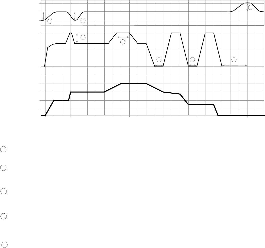
Multiple Boilers
175
180
SYSTEM
TEMPERATURE
Setpoint
2
0
50
100
3
185
1
5
4 54
Start
Lead Boiler
Start
1
st
Lag Start
2
nd
Lag Stop
1
st
Lag
0
1
2
3
Stop
2
nd
Lag Stop
Lead Boiler
PLANT LOAD
(# BOILERS REQURED) BOILER
FIRING RATE
2
Fast
Load
Change
Slow
Load
Change
High Fire Limit
(Parameter 37)
Boiler Start and Stop Peer-To-Peer Network Sequence Diagram
(3 boiler system shown, typical for up to 8 boilers)
- Lead Boiler Start
Water temperature is below the setpoint by more than the “On Point” differential
- Temperature Based Lag Boiler Start
Water temperature is below the setpoint by more than the “On Point” differential for longer than the adjustable
time delay (“Boiler On Delay” parameter).
- Modulation % Based Lag Boiler Start
The boiler modulation rate has been above the adjustable limit (“LL Start Trigger” parameter) for longer than the
time delay.
- Lag Boiler Stop
The boiler modulation rate has been below the adjustable limit (“LL Stop Trigger” parameter) for longer than the
time delay. Additionally, lag boilers are stopped when water temperature is above the setpoint by more than the
“Off Point” differential for longer than the “Boiler Off Delay” parameter)
- Lead Boiler Stop
The last boiler remains on line until the water temperature is above the “Off Point” setpoint for longer than the
time delay.
Notes
- The “Boiler Address” parameter assignment determines the boiler sequencing order.
- The Lead Boiler automatically rotates (when “Rotate” parameter is enabled) based on field adjusted time
(“Rotate After” parameter, default is 168 hours). When rotating, the lead boiler will move to the end of the lag
order and the 1st lag boiler will become the lead. The rest of the boilers will then move up in the lag order
accordingly.
- Lead Boiler is the first boiler to turn on and the last boiler to turn off, (First On, Last Off, FOLO).
- Lag Boilers are turned on in order and turned off in reverse order, (First On, Last Off, FOLO).
- Tripped boilers are replaced without waiting for the Boiler On Delay timer. If a tripped boiler becomes available
it is returned to service.
1
3
4
2
5
Sage Boiler Control Instruction Manual Page 9 of 56
Product Features
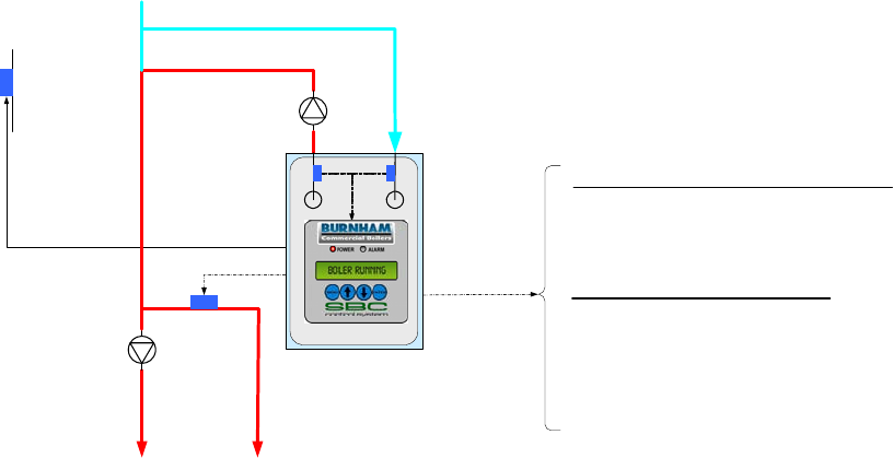
Single Boiler Control
Display Shows: Outlet Sensor & Local SP Mode
RJ11, RS-485 Communication
Peer-To-Peer Network
for Modulating Lead/Lag
Or
Modbus Network
for Touch Screen or EMS Monitoring
EMS System Hardwired Connections
Lockout Indicator (LO)
Soft Alarm (SO)
Remote On / Off (Enable) (RO)
Boiler Outlet
Temperature
(BO, BC)
Boiler Inlet
Temperature
(BI, BC)
Return
Water
Outside Air
Temperature
(O+, O-) Boiler
Circulator
System
Circulator
DHW
Override
Switch (DP)
System
Supply Water
Domestic Hot
Water (DHW)
Supply
Outlet Sensor & Local SP Mode Application Diagram
(Showing Relevant Connections)
Features
Setpoints
The operator selects the setpoint and on and off points
from the LCD display.
Modulation Rate Control
Boiler automatically modulates to maintain the boiler
outlet temperature at setpoint.
Call for Heat
The Call For Heat is determined by the setpoint, on
and off points and boiler outlet temperature.
Options
Outside Air Reset
If enabled, the Outside Air Sensor will automatically
adjusted the setpoint.
Warm Weather Shutdown (WWSD)
If enabled, the WWSD will disable a boiler start when
outside air temperature is above a Warm Weather
Shutdown (WWSD) setpoint.
Domestic Hot Water Priority (DHWP)
If enabled, the DHWP will adjust the setpoint to satisfy
the DHWP setpoint when a DHWP input (DP) is
energized.
Selecting This Control Mode
To select Outlet Sensor & Local SP Mode set the following
parameters:
System Configuration Menu:
Remote Control = “No”
Remote System Temperature Sensor = “No”
Remote On / Off (Enable) Input (RO) = Closed
[Jumper (RO) to (C)]
If the Remote On / Off (Enable) (RO) input is opened, the Call
For Heat Relay (CH) is de-energized.
Modbus Network
To establish a Modbus network set the following parameters:
Communication Menu:
Protocol = Modbus
Modbus Address = Give each boiler a unique address.
Baud Rate = Set identical to remote system
Parity = Set identical to remote system
Connect all boilers using a RJ11 ended telephone cable
If the Modbus network is activated the remote system may
monitor and/or control boiler operation. Refer to page 29 for
additional information.
Sage Boiler Control Instruction Manual Page 10 of 56
Product Features
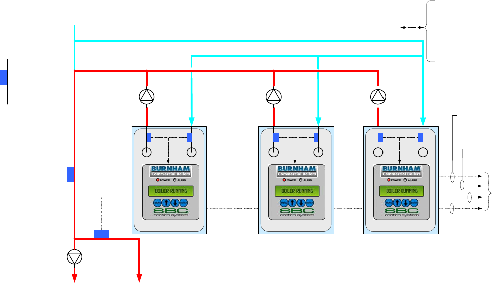
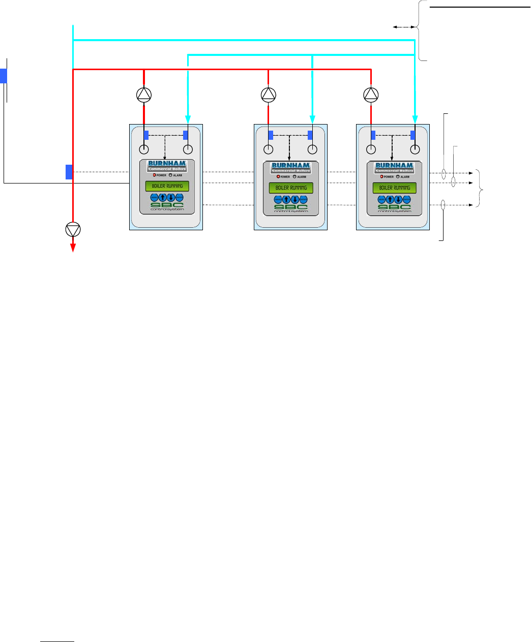
Multiple Boiler Control
Display Shows: Remote Sensor & Local SP Mode
Domestic Hot
Water Priority
(DP)
DHW Override
Switch (DP)
Connects to
Up to Eight
Boilers
RJ11, RS 485
Peer to Peer
Network
Remote System
Temperature
(R+,R-)
Outside Air
Temperature
(O+, O-) Boiler
Circulator
System
Circulator
Boiler
Circulator Boiler
Circulator Remote System
Temperature
(R+,R-)
Wired to Each
ECM Controller
Outside Air
Temperature
(O+, O-)
Boiler Outlet
Temperature
(BO, BC)
Boiler Inlet
Temperature
(BI, BC)
Remote Sensor & Local SP Mode Application Diagram
(Showing relevant connections for 3 boilers, typical for up to 8)
Features
Setpoints
The operator selects the setpoint and on and off points
from the LCD display.
Modulation Rate Control
Boiler automatically modulates to maintain the Remote
System Temperature (RST) at setpoint.
Call for Heat
The Call for Heat is determined by setpoint, on and off
points and RST. If a Peer-To-Peer network is activated, a
Call for Heat is also initiated when the Lead boiler
modulation rate % is above an adjustable High Fire Rate
Limit (parameter 37) for too long a time.
Options
Outside Air Reset
If enabled, the Outside Air Sensor will automatically
adjusted the setpoint.
Warm Weather Shutdown (WWSD)
If enabled, the WWSD will disable a boiler start when
temperature is above a Warm Weather Shutdown (WWSD)
setpoint.
Domestic Hot Water Priority (DHWP)
If enabled, the DHWP will adjust the setpoint to satisfy the
DHWP setpoint when a DHWP contact input (DP) is
closed. When multiple boilers monitor the DHWP input, an
isolated contact is required for each boiler.
Selecting This Control Mode
To select Remote Sensor & Local SP Mode set the
following parameters:
System Configuration Menu:
Remote Control = “No”
Remote System Temperature Sensor = “Control”
Remote On / Off (Enable) Input (RO) = Closed
[Jumper (RO) to (C)]
If the Remote On / Off (Enable) (RO) input is opened, the
Call For Heat Relay (CH) is de-energized.
If the Remote System Temperature Sensor (RST) fails, the
control mode is automatically switched to Outlet Sensor &
Local SP Mode.
Peer-To-Peer Network
To establish a Peer-To-Peer network follow the procedure
provided on page 28.
If the Peer-To-Peer network is activated the Lead boiler
controls modulation rate and Call for Heat for all
networked boilers. Up to 8 networked boilers are fired in
“Unison” (all at the same modulation rate).
Sage Boiler Control Instruction Manual Page 11 of 56
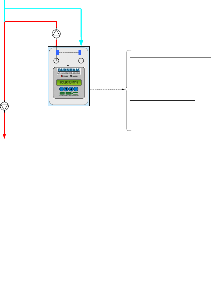
Product Features
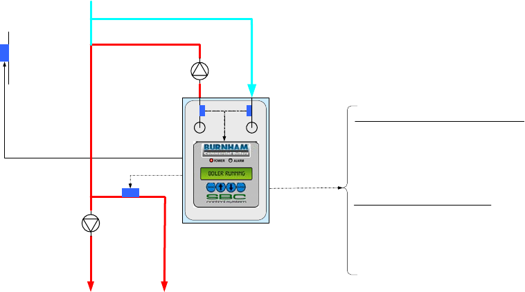
Energy Management System (EMS) Boiler Control
Display Shows: Outlet Sensor & Remote SP Mode
RJ11, RS-485 Communication
Peer-To-Peer Network
for Modulating Lead/Lag
Or
Modbus Network
for Touch Screen or EMS Monitoring
EMS System Hardwired Connections
Lockout Indicator (LO)
Soft Alarm (SO)
Remote On / Off (Enable) (RO)
Remote Setpoint (C+,C-)
Boiler Outlet
Temperature
(BO, BC)
Boiler Inlet
Temperature
(BI, BC)
Return
Water
Outside Air
Temperature
(O+, O-) Boiler
Circulator
System
Circulator
DHW
Override
Switch (DP)
System
Supply Water
Domestic Hot
Water (DHW)
Supply
Outlet Sensor & Remote SP Mode Application Diagram
(Showing relevant connections)
Features
Setpoints
The setpoint is determined by the Remote Input (C+,C-)
or Modbus Input and operator sets the on and off points
from the LCD display.
Modulation Rate Control
Boiler automatically modulates to maintain the boiler
outlet temperature at setpoint.
Call for Heat
The Call For Heat is determined by setpoint, on and off
points and boiler outlet temperature.
Options
Warm Weather Shutdown (WWSD)
If enabled, the WWSD will disable a boiler start when
temperature is above a Warm Weather Shutdown
(WWSD) setpoint.
Outside Air Temperature may be displayed only.
Outside Air Reset and Domestic Hot Water Priority input
(DP) are ignored.
Selecting This Control Mode
To select Outlet Sensor & Remote SP Mode set the following
parameters:
System Configuration Menu:
Remote Control = “Remote SP”
Remote System Temperature Sensor = “No”
Local / Remote Input (LR) = Closed
Remote On / Off (Enable) Input (RO) = Closed
[Jumper (RO) to (C)]
When the Local / Remote Input (LR) is open, Remote Input
(C+,C-) is ignored and Outlet Sensor & Local SP Mode is
active.
If the Remote On / Off (Enable) (RO) input is opened, the
Call For Heat Relay (CH) is de-energized.
Modbus Network
To establish a Modbus network set the following parameters:
Communication Menu:
Protocol = Modbus
Modbus Address = Give each boiler a unique address.
Baud Rate = Set identical to remote system
Parity = Set identical to remote system
Connect all boilers using a RJ11 ended telephone cable
If the Modbus network is activated the remote system may
monitor and/or control boiler operation. Refer to page 29 for
additional information.
Sage Boiler Control Instruction Manual Page 12 of 56
Product Features
Energy Management System (EMS) Boiler Control (continued)
Display Shows: Remote Sensor & Remote SP Mode
System
Supply Water
EMS System Connections
Lockout Indicator (LO)
Soft Alarm (SO)
Remote On / Off (Enable) (RO)
Remote Setpoint (C+,C-)
Return
Water
Connects to
Up to Eight
Boilers
RJ11, RS 485
Peer to Peer
Network
Remote System
Temperature
(R+,R-)
Outside Air
Temperature
(O+, O-) Boiler
Circulator
System
Circulator
Boiler
Circulator Boiler
Circulator Remote System
Temperature
(R+,R-)
Wired to Each
ECM Controller
Outside Air
Temperature
(O+, O-)
Boiler Outlet
Temperature
(BO, BC)
Boiler Inlet
Temperature
(BI, BC)
Remote Sensor & Remote SP Mode Application Diagram
(Showing relevant connections for 3 boilers, typical for up to 8)
Features
Setpoints
The setpoint is determined by the Remote Input (C+,C-)
and operator sets the on and off points from the LCD
display.
Modulation Rate Control
Boiler automatically modulates to maintain the Remote
System Temperature (RST) at setpoint.
Call for Heat
The Call For Heat is determined by setpoint, on and off
points and Remote System Temperature. If a Peer-To-
Peer network is activated, a Call for Heat is also initiated
when the Lead boiler modulation rate % is above an
adjustable High Fire Rate Limit (Parameter 37) for too
long a time.
Options
Warm Weather Shutdown (WWSD)
If enabled, the WWSD will disable a boiler start when
temperature is above a Warm Weather Shutdown
(WWSD) setpoint.
Outside Air Reset and Domestic Hot Water Priority input
(DP) are ignored.
Selecting This Control Mode
To select Remote Sensor & Remote SP Mode set the
following parameters:
System Configuration Menu:
Remote Control = “Remote SP”
Remote System Temperature Sensor = “Control”
Local / Remote Input (LR) = Closed [Jumper (LR) to (C)]
Remote On / Off (Enable) Input (RO) = Closed
[Jumper (LR) to (C)]
When the Local / Remote Input (LR) is open, Remote Input
(C+,C-) is ignored and Remote Sensor & Local SP Mode is
active.
If the Remote On / Off (Enable) (RO) input is opened, the
Call For Heat Relay (CH) is de-energized.
Peer-To-Peer Network
To establish a Peer-To-Peer network follow the procedure
provided on page 28.
If the Peer-To-Peer network is activated the Lead boiler
controls modulation rate and Call for Heat for all networked
boilers. Up to 8 networked boilers are fired in “Unison” (all
at the same modulation rate).
Sage Boiler Control Instruction Manual Page 13 of 56
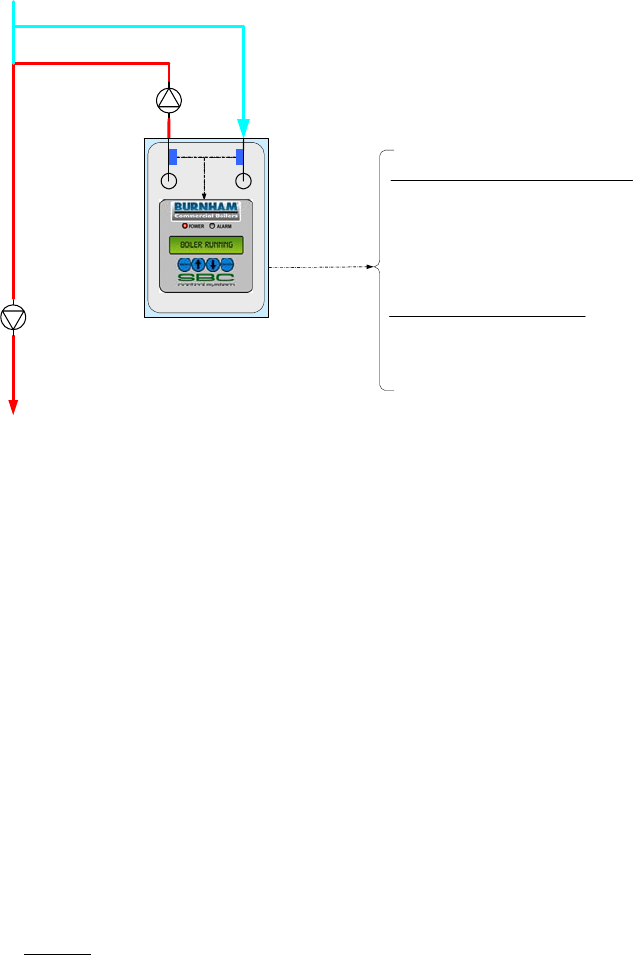
Product Features
Energy Management System (EMS) Boiler Control (continued)
Display Shows: Remote Control Mode
RJ11, RS-485 Communication
Modbus Network
EMS Monitoring and Control
Remote Firing Rate via Modbus
Remote on/off via Modbus
EMS System Hardwired Connections
Lockout Indicator (LO)
Soft Alarm (SO)
Remote On / Off (Enable) (RO)
Remote Setpoint (C+,C-)
Boiler Outlet
Temperature
(BO, BC)
Boiler Inlet
Temperature
(BI, BC)
Return
Water
Boiler
Circulator
System
Circulator
System
Supply Water
Remote Control Mode Application Diagram
(Showing relevant connections)
Features
Modulation Rate Control
The Remote Input (C+,C-) or Modbus input sets
modulation rate. The setpoint is ignored.
Call for Heat
The Call For Heat is determined by Remote On/Off
input (RO) or Modbus input. The on and off points are
ignored. The boiler will turn off if the water
temperature increases past the temperature set on the
Operational Temperature Limit.
Options
Outside Air Reset and Domestic Hot Water Priority
input (DP) and Warm Weather Shutdown are ignored.
Selecting This Control Mode
To select Remote Control Mode set the following parameters:
System Configuration Menu:
Remote Control = “Remote Mod”
Remote System Temperature Sensor = “Display Only”
Local / Remote Input (LR) = Closed [Jumper (LR) to (C)].
When the Local / Remote Input (LR) is open, Remote Input
(C+,C-) is ignored and Remote Sensor & Local SP Mode is
active.
Modbus Network
To establish a Modbus network set the following parameters:
Communication Menu:
Protocol = Modbus
Modbus Address = Give each boiler a unique address.
Baud Rate = Set identical to remote system
Parity = Set identical to remote system
Connect all boilers using a RJ11 ended telephone cable
If the Modbus network is activated the remote system may
monitor and/or control boiler operation. Refer to page 29 for
additional information.
Sage Boiler Control Instruction Manual Page 14 of 56
Product Features
Manual Boiler Control Mode
Display Shows: Manual Operation Mode and Lost Sensor Blind Mode
RJ11, RS-485 Communication
Modbus Network
EMS Monitoring
EMS System Hardwired Connections
Lockout Indicator (LO)
Soft Alarm (SO)
Remote On / Off (Enable) (RO)
Boiler Outlet
Temperature
(BO, BC)
Boiler Inlet
Temperature
(BI, BC)
Return
Water
Boiler
Circulator
System
Circulator
System
Supply Water
Manual Operation Mode and Lost Sensor Blind Mode Application Diagram
(Showing relevant connections)
MANUAL OPERATION MODE
Features
Modulation Rate Control
The operator sets the modulation rate. The setpoint is
ignored.
Call for Heat
The Call For Heat Relay (CH) is directly controlled by
the operator. The on and off points are ignored. The
boiler will turn off if the water temperature increases
past the temperature set on the High Temperature
Stop parameter.
Options
Outside Air Reset, Warm Weather Shutdown and
Domestic Hot Water Priority are ignored.
The Spare Output (VI) and Combustion Air Damper
(SO) outputs are energized when the operator starts
the boiler in manual mode.
Selecting This Control Mode
Manual Mode is activated from the Manual Mode
menu when Supervisor password is entered. Simply
set the Boiler Man/Auto parameter to “Man” and adjust
the Modulation Rate and Boiler On/Off menu items as
required. Once activated the green LED flashes. To
leave manual mode set the Boiler Man/Auto parameter
to “Auto”.
LOST SENSOR BLIND MODE
If both Remote System Temperature (RST) and boiler outlet
temperature and the Remote Control input signal (C,-C+) have
failed, the boiler is started and run continuously at the lowest
modulation rate.
If the controller has entered Lost Sensor Blind Mode, the user
may switch the boiler into manual mode or repair, replace or
reconnect required temperature sensors.
Sage Boiler Control Instruction Manual Page 15 of 56
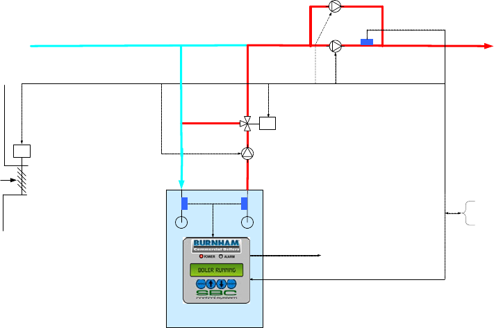
Product Features
Auxiliary Device Control
Standby System Pump
Start/Stop (SO)
Fresh Air
Supply
Modbus RS-485, RJ-11
Connection
M
M
System Pump
Feedback (SI)
Spare Output (VI)
System Pump
Start/Stop (SP)
Boiler Pump
Start/Stop (BP)
Mixing Valve
Control (MR, MS)
System
Supply Water
Return
Water
Combustion Air
Damper
Open/Close (SO) Boiler Outlet
Temperature
(BO, BC)
Boiler Inlet
Temperature
(BI, BC)
Energy Management
System (EMS)
Interface
Auxiliary Control Application Diagram
(Showing All Options)
Features
Mixing Valve
The primary function of the mixing valve is to protect the
boiler from thermal shock and sustained flue gas
condensation. When configured, the mixing valve output
compares both minimum return water temperature setpoint
to measured return water temperature and boiler
differential temperature setpoint to measured differential
temperature (boiler outlet minus inlet temperature).
If the boiler return water temperature drops below the
minimum inlet water temperature setpoint (“Min In H2O
Temp” parameter) or the differential temperature increases
above the maximum water differential temperature setpoint
(“Max H2O Delta T” parameter) the mixing valve opens to
allow hot boiler outlet water to blend with cold return water.
The valve repositions toward 0% recirculation after return
water increases above setpoint and the differential
temperature reduces below setpoint.
The mixing valve may be controlled manually from the
Manual Mode menu when Supervisor password is entered.
Simply set the Mixing Valve M/A parameter to “Man” and
adjust the Mixing Valve % as required. Once activated the
green LED flashes. To leave manual mode set the Mixing
Valve M/A parameter to “Auto”
Combustion Air Damper and Vent Inducer
When the Relay (CH) is closed, the Combustion Air
Damper (CAD) and Vent Inducer outputs are energized. If
the CAD open position is needed to be proven, a limit
switch may be wired in series with the Low Water Cut-off
Switch input (LC). The alarm Message may be modified to
reflect this change.
Boiler Pump
The Boiler Pump output (BP) may be configured as None,
Always On, Purge or Lead On by setting the Boiler Pump
(parameter 2) (refer to page 31):
Always On Boiler pump runs continuously.
Purge Boiler pump runs during a pump Prepurge
(Pump Prepurge (parameter 3) time before
boiler starts) while the boiler is running and
during a pump cooldown period (pump
cooldown maintains the boiler pump running
until the boiler outlet temperature is within
the Postpurge Delta (parameter 4) degrees
above the boiler inlet temperature).
Lead On: Boiler Pump runs continuously when the
boiler is the lead and during the fan pre-
purge, while the boiler is running and during
fan post purge when a lag boiler.
The boiler pump sequences are detailed on the boiler
sequence diagram on page 6.
System and Standby System Pump
When configured, the System Pump output (SP) is always
energized except when turned off by the Warm Weather
Shutdown feature. A Standby System Pump output (SO)
may be configured as a backup to the system pump. The
Standby System Pump is started based on the System
Pump Feedback input (SI).
Selecting This Control Mode
These control modes may be selected using the Boiler and
System Configuration menus.
Sage Boiler Control Instruction Manual Page 16 of 56
Front Panel
Features
POWER LED [Steady On Green LED] indicates power is available down
stream of the Sage Boiler Control’s on board fuse.
[Flashing On Green LED] indicates manual mode operation
for boiler modulation
ALARM LED [Steady On Red LED] indicates an alarm is active.
[Flashing On Red LED] indicates a lockout alarm is active
and a manual reset may be required
SCREEN 2 line by 16 character display provides operational, alarm,
sequence status, configuration and diagnostic user interface
ENTER The ENTER key has no function in display mode. The
ENTER key is used to select menus, menu items and save
edited parameters as follows:
Select Mode (steady text): Press ENTER to change into Edit
Mode or select a menu or menu item
Edit Mode (blinking text): Press ENTER to save the current
value. Press MENU to cancel the current editing operation
UP, DOWN Select Mode (steady text): Press UP, DOWN to change the
selected display and move up and down menu items.
Edit Mode (blinking text): Press UP, DOWN to increases or
decreases the value of the number being edited, or scrolls
through a list of choices.
MENU Press and hold MENU to change to the Main Menu screen.
When in a sub menu screen, press MENU to move to the
next higher menu. When in Edit Mode (blinking text) Press
MENU to cancel the current editing operation
Sage Boiler Control Instruction Manual Page 17 of 56
Front Panel
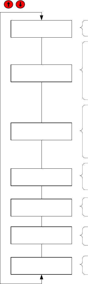
Display Mode
All values shown in Display Mode are for display only and can not be adjusted by the operator. The
keys scroll through the Display Mode screens:
Boiler State
Standby boiler state shown, refer to the top of page 6 &
7 for explanation of each boiler state
Alarm Message
Low Inlet Temp alarm shown, refer to page 41 for
explanation of all possible alarm messages, the
alarm line is left blank when no alarm is active
OUT Boiler Outlet Temperature
IN Boiler Inlet Temperature
RST Remote System Temperature
(visible when ‘Remote Sensor’ = Display Only or
Control)
OA Outside Air Temperature
(visible when ‘Outdoor Sensor’ = Display Only or
Outdoor Reset)
OUT or RST Boiler Outlet or Remote System Temperature
(Remote System when ‘Remote Sensor’ = Control)
SP Active Setpoint
MOD RATE Modulation Rate
SH Space Heating (active when DH is not)
DH Domestic Hot Water Priority
(visible when ‘DHWP’ = Yes and DP input is true)
In Boiler Inlet Temperature
SP Min In H2O Temp
MIX VALVE Modulation Rate
Control Mode Outlet Sensor & Local SP Mode message shown, refer
to page 2 for an overview of each control mode
LEAD BOILER (0 – 8) Lead Boiler, when zero is displayed modulating
lead-lag functions are not available
CYCLES Number of boiler cycles
HOURS Number of boilers operating hours
Standby
Low Inlet Temp
In 180F SP 130F
MIX VALVE 100%
OUT 189F SP 180F
MOD RATE SH 100%
Outlet Sensor &
Local SP Mode
OUT 189F IN 180F
RST 189F OA 180F
Cycles #,###,###
Hours #,###,###
LEAD BOILER 8
Home Screen
The Boiler State and Alarm Message screen is the ‘Home Screen’ and is reverted to when no key has been selected for
longer than 30 minutes.
Alarm LED
New alarms illuminate the alarm LED and energize an alarm output (SO) (if enabled). If a lockout condition is detected,
the alarm LED will blink and the lockout indication output (LI) is energized. The display Message is cleared and relays
de-energize when the alarm condition is cleared.
Sage Boiler Control Instruction Manual Page 18 of 56
Front Panel
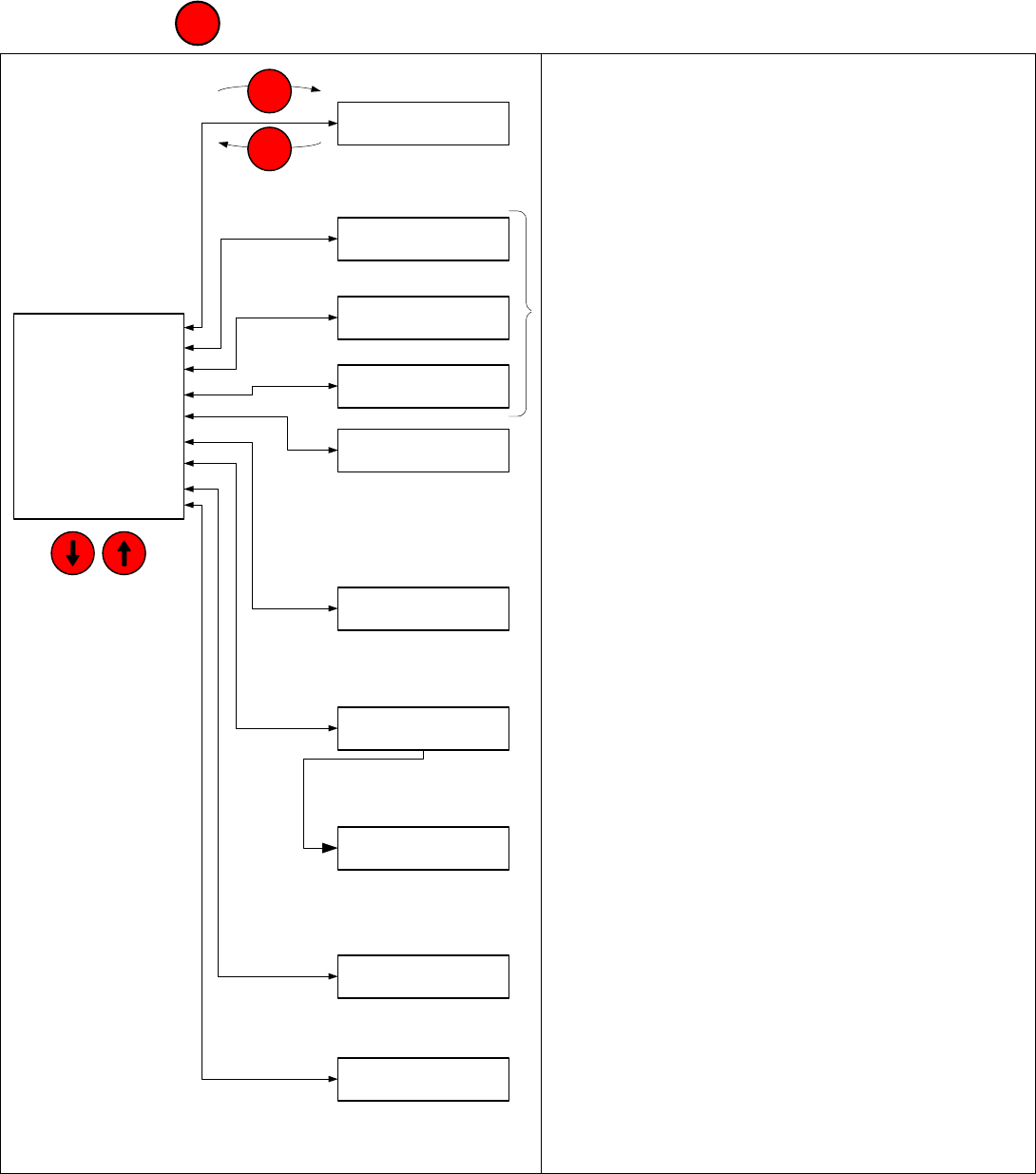
Display Navigation
Press and hold the key to leave the Display Mode and access the Main Menu:
DISPLAY MODE
BOILER CONFIG
SYSTEM CONFIG
SETUP
SETPOINTS
COMMUNICATION
DIAGNOSTICS
SECURITY
MANUAL MODE
Arrow Keys:
Up / Down
through Lists
BOILER CONFIG
SYSTEM CONFIG
SYSTEM
SETPOINTS
DIAGNOSTICS
DISPLAY MODE
SETUP
SECURITY
ENTER
Main Menu
Sub Menus
COMMUNICATION
MANUAL MODE
MENU
Display Mode Displays: Boiler operating status, Display
Only, Values Are Not Editable from this display
Configuration and Setup Menus: Sensor, boiler and
system options selections
(refer to page 31)
Setpoints Menu: Operational, On, Off, Min & Max
Setpoints, Editable Values
(refer to page 19)
Communication Menu
Modbus and Peer-To-Peer Network Selections
(refer to page 27)
Diagnostic Menu: Fault and Low Inlet Temp history,
Input & Output Status
(refer to page 41)
System Menu: Software revision, parameter code and
sensor calibration
(refer to page 43)
Security Menu: Supervisor and Factory access
(refer to page 45)
Manual Mode: User set Call For Heat and modulation
rate. Menu is visible when supervisor password is
entered (Refer to page 38)
MENU
Sage Boiler Control Instruction Manual Page 19 of 56
Front Panel
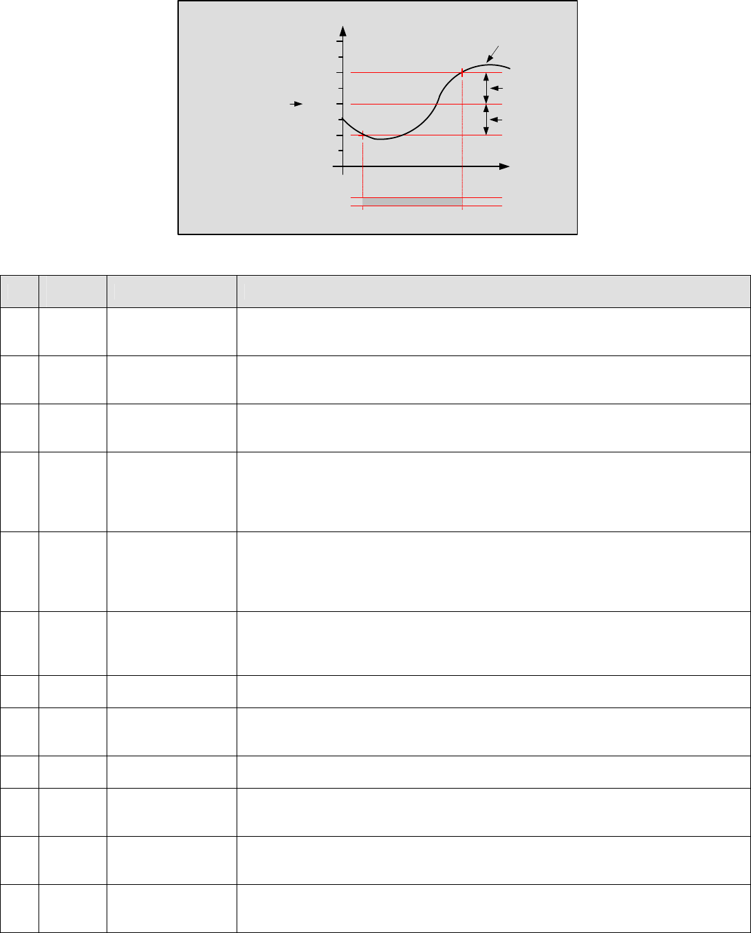
Setpoints Menu
Time
Deg F
175
185
180
Water
Temperature
On Point
Operational SP
Off Point
Call For Heat
Relay (CH)
Call For Heat Settings
No. Factory
Setting Range / Choices Parameter and Description
70 180 60 F to 230 F Operational Setpoint
Setpoint used in Local Setpoint Mode when not servicing a Domestic Hot Water
Priority (DHWP) request
71 -5 0 F to –99 F On Point
The boiler starts when the water temperature drops ‘On Point’ degrees below the
setpoint.
72 15 0 F to 99 F Off Point
The boiler stops when the water temperature rises ‘Off Point’ degrees above the
setpoint.
73 210 60 F to 230 F
High Temp Stop
The boiler stops when the boiler outlet water temperature is above the High
Temperature Stop setpoint. This setpoint is active in every control mode. If the
lead boiler’s boiler outlet temperature is above the high temperature stop all
boilers are stopped.
74 180 140 F to 230 F
*DHWP Setpoint
The Domestic Hot Water Priority (DHWP) Setpoint is active when DHWP Input
(DP) closes and “DHWP” parameter is set to “yes” and Local SP Mode is
selected. When the contact is closed, the boiler outlet is maintained at, or above,
the DHW Setpoint.
75 60 40 to 90 F
*WWSD Setpoint
The Warm Weather Shutdown (WWSD) Setpoint used to disable boiler and or
system pump operation when enabled by setting the “WWSD” parameter to
“WWSD of Boiler”, “WWSD of Sys Pump” or “Both”
76 230 140 F to 230 F Max SP
The Maximum Operational Setpoint for all possible Local and Remote modes
77 140 60 F to 230 F Min SP
The Minimum Operational Setpoint is the lower limit for all Local and Remote
modes
78 120 110 F to 235 F Min BIT
Low Boiler Inlet Temperature alarm and event setpoint.
79 130 110 F to 180 F *Min In H2O Temp.
Minimum Inlet Water Temperature setpoint used as the Mixing Valve inlet
temperature setpoint.
80 50 20 F to 50 F *Max H2O Delta T
Maximum Water Differential (Boiler Outlet minus Boiler Inlet) Temperature
setpoint used as the Mixing Valve differential temperature setpoint.
81 40 20 F to 50 F Max Delta T Hold
Maximum Water Differential (Boiler Outlet minus Boiler Inlet) Temperature used
to hold modulation rate at low fire.
* Only visible when parameter enabled on the configuration and setup menus

Sage Boiler Control Instruction Manual Page 20 of 56
Installation
Mounting & Wiring Sensors
The Sage Boiler Control (SBC) is mounted in the burner control panel and wired to the burner circuitry at the factory.
These installation instructions will explain how the boiler inlet and outlet water temperature sensors are mounted in the
boilers supply and return connections and wired to the SBC. Keep a copy of the boiler installation manual on hand to
supplement these instructions.
MPC Boiler
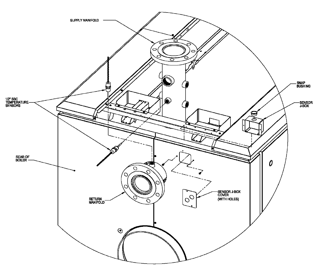
1. Mount Boiler Inlet and Outlet Water Temperature Sensors
a. Remove one of the ½” immersion temperature sensors from the Sage Boiler Control Parts Carton and
apply thread sealant to the threads between the probe and hex shoulder.
b. Install the sensor in the ½” tapping facing upward on the MPC return manifold. Refer to Figure 1. (If
an RWMT positioning plug has already been installed in this tapping, remove it and replace it with the
sensor.) Make sure that the hole in the top of the return water mixing tube is aligned with the tapping
in the manifold and that the sensor probe slides through this hole without interference. Wrench the
sensor until watertight.
c. Remove the other ½” temperature sensor from the Sage Boiler Control Parts Carton and apply thread
sealant to the threads between the probe and hex shoulder.
d. Install the sensor in the ½” supply manifold tapping that faces the rear of the boiler. Refer to Figure 1.
Wrench the sensor until watertight.
2. Install Sensor Junction Box in Boiler Jacket
a. The temperature sensor wiring can be run to the burner control panel under the boiler jacket, using the
internal wiring chaseway, or it can be run externally, in rigid or flexible conduit. If the sensor wiring will
be run externally, proceed immediately to Part 4 of these instructions. If the sensor wiring will be run
within the boiler’s internal chaseway, continue to step b. below.
b. If the jacket front, intermediate, and rear top panels have already been installed, remove them (using
the MPC manual’s installation instructions and working in reverse).
c. If the boiler control wiring has already been installed in the rear top panel, remove the two (2) screws
from the rear flange of the panel, slide the panel back, and tilt it upward in order to gain access to the
primary internal junction box.
d. Remove the sensor J-box and black snap bushing from the Sage Boiler Control Parts Carton and
install the bushing in the 7/8” hole in the J-box. Mount the sensor J-box (with the snap bushing facing
upward) to the inside surface of the right split rear panel using two (2) of the #8 x ½” lg. hex head SMS
provided. See Figure 1.
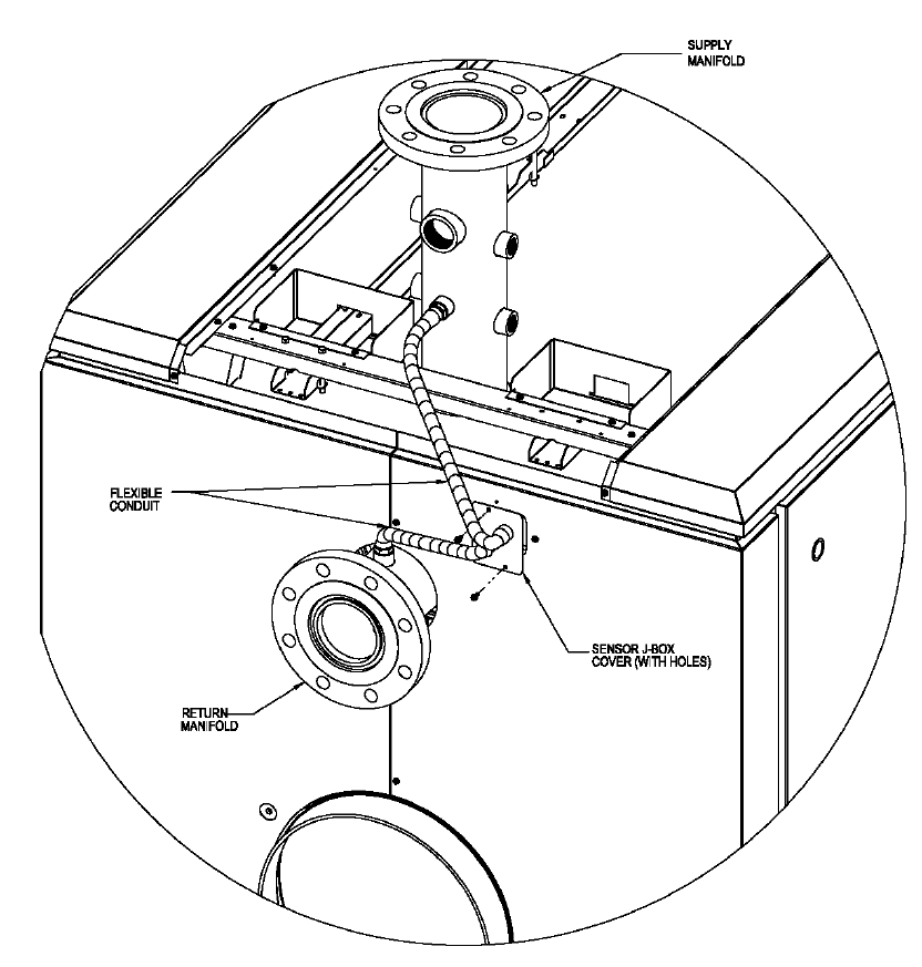
3. Install and Connect Temperature Sensor Wiring (If Using Internal Wiring Chaseway)
a. Remove the painted sensor J-box cover (with holes) from the carton. If the blank cover plate is
already mounted on the right rear split panel, remove it. Using flexible conduit and the appropriate
conduit connectors (supplied by others), connect the inlet and outlet temperature sensor wiring to the
two (2) holes in the sensor J-box cover plate. Refer to Figures 1 and 2. The conduit length should be
sufficient to allow the cover plate to be installed over the sensor J-box opening in the right rear panel.
b. Install one length of shielded electronic wire cable (supplied by others). To prevent electrical
interference from the internal control/safety circuit wiring harness already installed in the chaseway,
use foil-shielded, 3-conductor (22 AWG), UL-listed cable, as a minimum. The cable length should be
sufficient to reach from the sensor J-box to the SBC terminals in the burner control panel, following the
same path as the internal wiring harness.
c. Pull one end of the shielded cable through the snap bushing on top of the sensor J-box. Trim any
excess length from the sensor wires and connect them to the shielded cable leads in the following
manner:
i. Connect one wire from each sensor to the black wire in the shielded cable.
ii. Trim the shielded cable’s silver drain wire, so that it will not come in contact with any metal
surfaces within the J-box. The drain wire is not used at this end of the cable.

Sage Boiler Control Instruction Manual Page 21 of 56
iii. Connect the second wire from the inlet temperature sensor to one of the remaining wires in
the cable. Be sure to note the color of the cable wire to ensure that it is connected to the
correct terminal on the SBC in later steps.
iv. Connect the second wire from the outlet temperature sensor to the remaining wire in the
cable. Be sure to note the color of the cable wire to ensure that it is connected to the correct
terminal on the SBC in later steps.
d. Mount the sensor J-box cover to the right rear panel using two (2) of the #8 x ½” lg. hex head SMS
provided. See Figure 2. Make sure that all of the exposed wires fit inside of the sensor J-box and that
none of them are pinched once the cover plate is installed.
e. Using wire ties, secure the shielded cable to the primary junction box and chaseway channel in the
same manner as the internal wiring harness, as shown in the MPC installation manual.
f. When the cable reaches the end of the chaseway at the front of the boiler, secure it to the vertical
frame rail using the same cable clamps that were installed with the internal wiring harness. Refer to
the MPC installation manual for details. It may be necessary to temporarily loosen the screws holding
the cable clamps in place, in order to fit the shielded cable through each loop along with the internal
wiring harness. If it is necessary to loosen these screws, the jacket front panel will have to be
removed (if already installed).
g. The shielded cable should exit the boiler jacket through the unused hole in the side of the front panel.
Using flexible conduit and the appropriate conduit connectors (supplied by others), connect the
shielded cable to the burner control panel through one of the panel knockouts near the SBC.
h. Connect the wire leads to the appropriate SBC terminals, as shown on the “External Connections”
label on the back of the control. (These terminals are also shown on the “Installation: Terminal Layout”
page of this manual). For easier access to the SBC terminals in Power Flame burner control panels,
remove the screws at the left and right edges of the top panel and rotate the top panel upward, around
the hinge at the top rear of the panel box. (See the Power Flame burner manual for details and
illustration.)
i. Connect the black wire and silver drain wire from the cable to the SBC’s “BC” terminal.
j. Reinstall any jacket panels that may have been removed.
4. Install and Connect Temperature Sensor Wiring (If Using Electrical Conduit Outside of the Boiler Jacket)
a. Using flexible conduit and the appropriate conduit connectors (supplied by others), run the inlet and
outlet temperature sensor wiring to a suitable metal junction box. To prevent electrical interference
from other wiring in the burner control panel, connect the sensor wires to foil-shielded, 3-conductor (22
AWG), UL-listed cable, as a minimum. Do not make any other wiring connections inside of this
junction box. Trim any excess length from the sensor wires and connect them to the shielded cable
leads in the following manner:
i. Connect one wire from each sensor to the black wire in the shielded cable.
ii. Trim the shielded cable’s silver drain wire, so that it will not come in contact with any metal
surfaces within the junction box. The drain wire is not used at this end of the cable.
iii. Connect the second wire from the inlet temperature sensor to one of the remaining wires in
the cable. Be sure to note the color of the cable wire to ensure that it is connected to the
correct terminal on the SBC in later steps.
iv. Connect the second wire from the outlet temperature sensor to the remaining wire in the
cable. Be sure to note the color of the cable wire to ensure that it is connected to the correct
terminal on the SBC in later steps.
b. Using properly supported conduit and the appropriate connectors (supplied by others), connect the
shielded cable to the burner control panel through one of the panel knockouts near the SBC.
c. Connect the wire leads to the appropriate SBC terminals, as shown on the “External Connections”
label on the back of the control. (These terminals are also shown on the “Installation: Terminal Layout”
page of this manual). For easier access to the SBC terminals in Power Flame burner control panels,
remove the screws at the left and right edges of the top panel and rotate the top panel upward, around
the hinge at the top rear of the panel box. (See the Power Flame burner manual for details and
illustration.)
Connect the black wire and silver drain wire from the cable to the SBC’s “BC” terminal.
Sage Boiler Control Instruction Manual Page 22 of 56
Installation
Mounting & Wiring Sensors (Cont.)
Figure 1: Installation of SBC Components (Part 1)
Sage Boiler Control Instruction Manual Page 23 of 56
Installation
Mounting & Wiring Sensors (Cont.)
Figure 2: Installation of SBC Components (Part 2)
Sage Boiler Control Instruction Manual Page 24 of 56
Installation
Mounting & Wiring Sensors (Cont.)
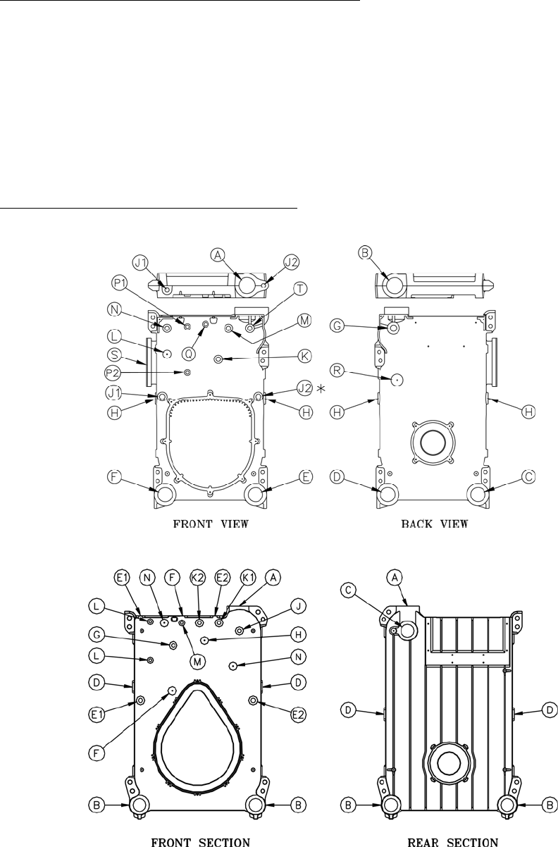
V9/V11 Boilers
1. Mount Boiler Inlet and Outlet Water Temperature Sensors
a. Remove one of the ½” immersion temperature sensors from the Sage Boiler Control Parts Carton and
apply thread sealant to the threads between the probe and hex shoulder.
b. Install the supply sensor in the 3/4” tapping T or J (V9, V11 respectfully) using a ¾” x ½” bushing.
Refer to Figure 3. Wrench the sensor until watertight.
c. Remove the other ½” temperature sensor from the Sage Boiler Control Parts Carton and apply thread
sealant to the threads between the probe and hex shoulder.
d. Install the return sensor at the lower rear return tapping, using a short 3” nipple and a 3” x 3” x 3” tee
with the branch of the tee bushed down to ½” (or, use a 3” x 3” x ½” tee, if available). For V9, use
tapping C and for V11, use tapping B. Refer to Figure 3. Wrench the sensor until watertight.
2. Install and Connect Temperature Sensor Wiring
Follow the instructions above for the MPC sensor wiring, Step 4 “If Using Electrical Conduit Outside of the
Boiler Jacket”.
V9
V11
Figure 3

Sage Boiler Control Instruction Manual Page 25 of 56
Installation
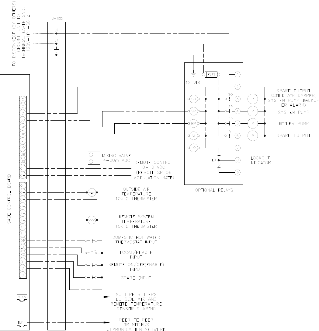
Terminal Layout
Remote System Temperature
(10k ohm Thermister, 5Vdc)
Outside Air Temperature
(10k ohm Thermister, 5Vdc)
Domestic Hot Water Priority
Local / Remote
Remote On / Off (Enable)
Spare Input (Programmable)
12 Vdc Common
Remote Firing Rate or
Setpoint Input (0-10 Vdc)
Mixing Valve Output
(4-20 mAdc)
Alarm Indicator
Vent Inducer Start/Stop
Boiler Pump Start/Stop
System Pump Start/Stop
Spare Output (Programmable)
12Vdc Common
CA
OO
Alternate Connection For
Outside Air Temperature and
Remote System Temperature
(10k ohm Thermister, 5Vdc)
Call For Heat Output
Low Water Cutoff Switch Input Boiler Outlet Temperature
(10k ohm Thermister, 5Vdc) Common
Boiler Inlet Temperature
Boiler Peer-To-Peer
Communication
Network
V- V+ P- P+
GP WFHL
Power Common (-24 Vac)
Power Supply (+24 Vac)
Flame Safeguard Alarm
(24 Vac)
Fuel Valve Energized
(24 Vac)
P-, P+ - Firing Rate Demand (0-10 Vdc, PWM)
V-, V+ - Firing Rate Demand (0-10Vdc)
OO - Burner On/Off Switch
WF - Low Water Flow Switch
GP - Gas Pressure Switch
HL - Operating or High Limit
CA - Low Combustion Air Flow
RJ-45
(8 pin)
O+
O-
O-
R+
R+
R-
R-
DP
O+
LR
RO
SI
C
C
C
SP
BP
VI
LO
C-
C+
MR
MS
SO
C
C
BC
BO
BI
CH
LC
CPRALCS
RJ-11
(6 pin)
12 Vdc,
0.5 A max total
for LO, VI, BP,
SP and SO
!
24
Vac
12
Vdc
Label 901 a
24
Vac
Sage Boiler Control Terminal Arrangement (rear view)
Sage Boiler Control Instruction Manual Page 26 of 56
Installation
External Connections
System Water Temperature Sensor
Mount the sensor in the common header downstream of all boiler connections. Locate the sensor a minimum distance
of 10 straight pipe diameters from the from flow disturbing fittings.
Outdoor Air Temperature Sensor
Mount the temperature sensor on an outside wall out of direct sunlight, preferably on a north facing wall. Do not mount
sensor near exhaust of any kind, as this may affect readings.
Sage Boiler Control Instruction Manual Page 27 of 56
Installation
External Connections (Continued)
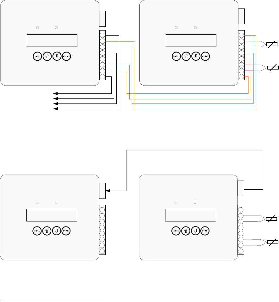
Outside Air and Remote System Temperature Sensor RJ45 Connection
All boilers may be connected to the remote system temperature (RST) and the outdoor air temperature (OAT) sensors.
Only one of each type sensor is needed for connections with up to eight boilers. The lead boiler is automatically
enabled to monitor the sensors. As the boiler lead rotates the sensor monitoring is automatically transferred to the new
lead boiler.
Two Boiler
RJ45 Connection Diagram
(Refer to Note 2)
Boiler 1
Boiler 2
Multiple Boiler Connection Diagram
(Using the extra O+, O-, R+ & R- terminals to daisy chain
the boilers together )
Outside Air
Temperature
Remote
System
Temperature
O+
O-
O-
R+
R+
R-
R-
O+
Alarm
BOILER RUNNING
Power
O+
O-
O-
R+
R+
R-
R-
O+
Alarm
BOILER RUNNING
Power
Connects to
Up to 8 Boilers
Boiler 1
Boiler 2
Outside Air
Temperature
Remote
System
Temperature
O+
O-
O-
R+
R+
R-
R-
O+
Alarm
BOILER RUNNING
Power
RJ-45
O+
O-
O-
R+
R+
R-
R-
O+
Alarm
BOILER RUNNING
Power
RJ-45
RJ-45
RJ-45
Notes
1. Used Only For Peer-To-Peer Network. When using Modbus Network wire Outside Air and Remote System sensor
to only one boiler.
2. Wiring from the Outside Air and Remote System Temperature sensors should use low impedance, shielded, twisted
pair wire and go directly to the terminals on any one boiler. Signal wiring should not be run in the same conduit with
power wiring. Wire shields may be connected to the common terminal (C) located on the same terminal block with
the outside air and remote system temperature connections.
3. The RJ45 sensor cables need to be a straight through type cable that connects each pin of the connector on one
end to it’s identical pin on the opposite end. Up to a total of three boilers may be connected using a RJ45 splitter.
When connecting more than three boilers, it is recommended, and may be more convenient, to use the extra O+, O-
, R+ & R- terminals to daisy chain the boilers together (eliminating the need for RJ45 cables and splitters and
reducing the loop impedance).
Sage Boiler Control Instruction Manual Page 28 of 56
Installation
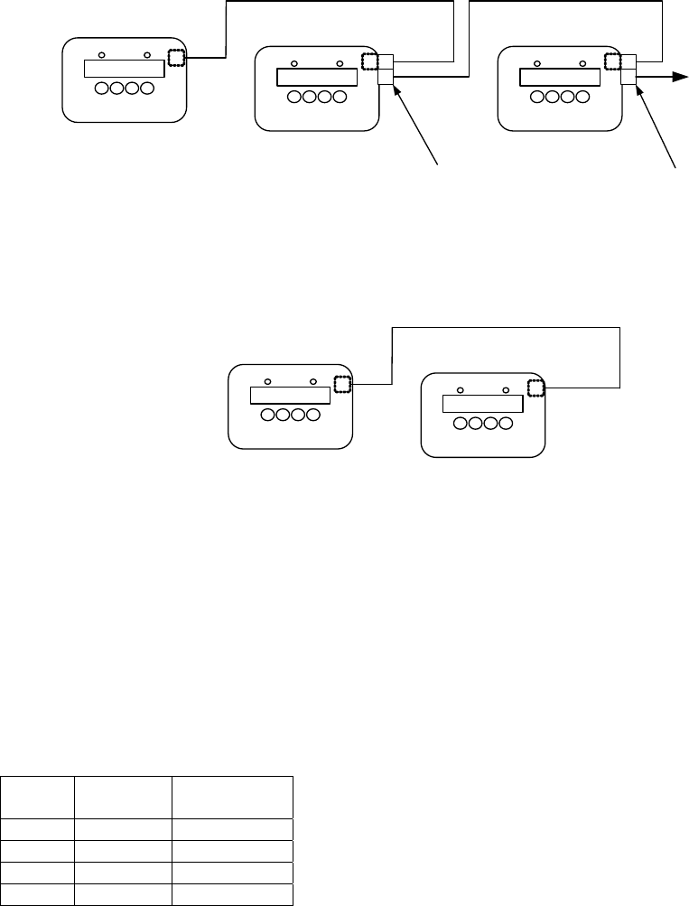
Communication
The Peer-To-Peer or Modbus networks allow boiler information, including modulation rate and on/off commands, to be
sent via a standard phone cable thus avoiding the cost, time and complexity of wiring multiple signals.
Sage Control
Sage Control
Two Boiler
RJ11 Connection Diagram
Boiler 1 Boiler 2
RJ11
RJ11
Sage ControlSage Control
Sage Control
Multiple Boiler
RJ11 Connection Diagram
RJ11
RJ11 Splitter
(Not Included)
Connects to
Up to 8 Boilers
Boiler 1 Boiler 2 Boiler 3
RJ11
RJ11
RJ11 Splitter
(Not Included)
Or Building
Automation System
(BAS) Modbus
Connection
When Wiring Modbus Communication to a Building Automation System (BAS)
The Modbus communication connects to the same RJ11 port that is used by the peer-to-peer communication. Connect
one end of the RJ11 cable to the SBC and cut off the other end of the cable to access the individual conductors. The
SBC is a 2-wire Modbus communication. Connect the "A" and "B " terminals of a four wire or six wire phone cable (as
shown below) to the BAS terminals. The SBC includes two sets of A and B connections, where the A represents the
active transmission state of the RS485 transmitter (as opposed to the line idle state). You need only to wire to one of the
"A" terminals and one of the "B" terminals.
Phone cable signals (4 wire) - connect to pin black or yellow and red or green:
Wire
Color Slot
Number Connection
Black 1 A
Red 2 B
Green 3 B
Yellow 4 A
Notes
1. Use standard phone cables (although ones that have all six wires terminated at each end) and splitters to
connect each boiler.
2. Please note that all connections between boilers must be kept as short as possible. The maximum cable length
between boilers must be kept under 25 feet (average distance between all boilers).
3. In all cases, the wires should be routed away from any obvious sources of electrical noise or magnetic fields
(motors, fluorescent lights, contactors, spark generators, etc.). Use a separate conduit and junction box from
the power wiring.
4. SBC power supply common must be grounded at each boiler to enable network communication.

Sage Boiler Control Instruction Manual Page 29 of 56
Installation
Communication (Continued)
The Sage Boiler Control communication selections are found on the Communication Menu. Press and hold the
key to leave the Display Mode and access the Main Menu:
Use the keys scroll down to the Communication Menu and push the key:
Communication Menu
No. Factory
Setting Range / Choices Parameter and Description
90 Peer to
Peer Peer to Peer
Modbus
Protocol
Selects between Peer-To-Peer (multiple boiler Lead/Lag control network) and
a Modbus slave communication.
91 1 1-247 Modbus Address
Each boiler must be given a unique address. Only visible when Protocol
equals Modbus.
92 19.2 9.6
19.2
38.4
Baud Rate
Units are 1000 Bits Per Second (KBPS). Only visible when Protocol equals
Modbus.
93 None Odd
Even
None
Parity
Only visible when Protocol equals Modbus.
94 30 1-120
Seconds Timeout
Only visible when Protocol equals Modbus.
95 Messages Rcvd
Diagnostic tool used to confirm wiring and Modbus master configuration.
Only visible when Protocol equals Modbus.
96 Messages Sent
Diagnostic tool used to confirm wiring and Modbus master configuration.
Only visible when Protocol equals Modbus.
97 1 1 to 8
Boiler Address
Each boiler must be given a unique address. The boiler address assignment
determines the boiler sequencing order. A value of 0 disables the network
communications. Only visible when Protocol equals Peer to Peer.
98 - - 6 - - - 321
Online Status
Each space can be either the boiler address or a ‘ - ‘ depending on whether
there is a boiler of that address on-line. Only visible when Protocol equals
Peer to Peer.
Example: - - 6 - - - 321 indicates that boilers 6,3,2 and 1 are online
MENU
ENTER
Sage Boiler Control Instruction Manual Page 30 of 56
Installation
Peer-To-Peer Network
The Sage Boiler Control includes a dependable Peer-To-Peer communication network. This network allows multiple
boiler modulating lead/lag control and status signals to be transferred between boilers. In order to successful use this
network certain requirements must be followed.
Network Relevant & Updated Parameters
When using the Peer-To-Peer network certain “Network Relevant” parameters must be configured the same in all
boilers (refer to Appendix B for parameter identification). To facilitate the configuration of these “Network Relevant”
parameters, a network update feature has been included. Once communications is established between all boilers in a
system, changing to a “Network Relevant” parameter at the keypad of any boiler will update that parameter in all boilers.
In addition to the “Network Relevant” parameters, other common parameters are also “Updated” over the network
(although it is not necessary for them to be set identically among boilers on the network). If you wish to configure them
differently among boilers, you will have to disconnect the boiler from the network while you change them to prevent the
other boiler from being changed as well. “Network Relevant” and additional “Updated” parameters are identified in
Appendix B, Parameter Summary.
Initially Establishing Peer-to-Peer Communication
A Peer-to-Peer network is established as follows:
1. Assign all boilers a unique Boiler Address between 1 and 8 and set the Protocol to Peer-to-Peer
2. Connect all boilers using a RJ11 ended telephone cable
3. Configured all “Network Relevant” parameters identically on all boilers. Unexpected boiler behavior may result if
these parameter values differ among boilers on the network. When “Network Relevant” parameters are identical
the ‘Param Code’ parameter will be identical on each boiler (refer to page 43 for parameter location).
4. When two or more boilers are properly configured for communication, the controllers “auto detect” each other and
shares information.
Re-Establishing Peer-to-Peer Communication After an individual boiler Communication Failure
A Peer-to-Peer network is re-established as follows:
1. Ensure Boiler address is between 1 and 8 and is unique
2. Ensure the Protocol parameter is set to Peer-to-Peer
3. Use the ‘Param Code’ parameter to check that “Network Relevant” parameters are configured identically (refer to
page 43 for parameter location).
4. Remove control power from the boiler
5. Connect the boiler to the network using a RJ11 ended telephone cable
6. Apply control power to the boiler
7. The network will “auto detect” the new boiler and assign it a position in the sequence based on the boiler address.
When a boiler is operated as a stand alone boiler, away from the network, it establishes itself as a lead boiler. If this
stand alone boiler is simply re-connecting to a network of operating boilers there is a potential that boiler operation will
be disrupted as the new boiler becomes lead. This potential is avoided by following the above Re-Establishing
procedure.

Sage Boiler Control Instruction Manual Page 31 of 56
Installation
RS485 Modbus Network
The Sage Boiler Control includes a dependable Modbus communication network. This network allows boilers to be
controlled and/or monitored by a remote system via a RS485 Modbus communication network. Each Sage Boiler
Control is a Modbus slave with the following available boiler information:
Modbus Addresses
Coil Address Description Read/Write coil = 0 coil = 1 Notes
00001 Outdoor Air Reset Enable/Disable Disable Enable
00002 Domestic Hot Water Priority (DHWP) Disable Enable
00003 Local / Remote Local Remote
00004 Remote On / Off Modbus Command Y Off On 1
00005 Spare Input (Programmable) Off On
00006 Low Water Cutoff Switch Off On 2
00007 Burner On / Off Switch Off On 2
00008 Low Water Flow Off On 2
00009 High and Low Gas Pressure Switches Off On 2
00010 Operating or High Limit Off On 2
00011 Low Combustion Air Flow Off On 2
00012 Fuel Valve Energized Off On
00013 Flame Safeguard Alarm Off On
00014 Call For Heat (CFH) Off On
00015 General Alarm Off On 4
00016 Vent Inducer Off On
00017 Boiler Pump Off On
00018 System Pump Off On
00019 Spare Output (Programmable) Off On
00020 State Boiler Disabled Off On 3
00021 State Weather Shutdown Off On 3
00022 State Lockout Off On 3
00023 State Pump Purge Off On 3
00024 State Limit Hold Off On 3
00025 State Purge/Pilot Ign Off On 3
00026 State Low Fire/Ignition Off On 3
00027 State Main Ignition Off On 3
00028 State Low Fire Hold Off On 3
00029 State Boiler Running Off On 3
00030 State Fan Post Purge Off On 3
00031 State Pump Cool Down Off On 3
00032 State Standby Off On 3
00033 Annunciator Low Water Level Off On 4
00034 Annunciator Off Switch Off On 4
00035 Annunciator Low Water Flow Off On 4
00036 Annunciator Fuel Limit Off On 4
00037 Annunciator High Temp Limit Off On 4
00038 Annunciator Low Air Flow Off On 4
00039 Annunciator FSG Lockout Off On 4
00040 Annunciator Outlet Temp Fail Off On 4
00041 Annunciator Inlet Temp Fail Off On 4
00042 Annunciator OA Temp Fail Off On 4
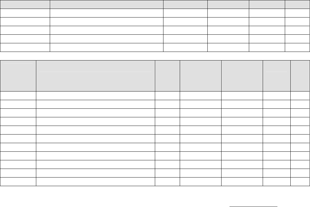
Sage Boiler Control Instruction Manual Page 32 of 56
Installation
RS485 Modbus Network
Modbus Addresses (continued)
Coil Address Description Read/Write coil = 0 coil = 1 Notes
00043 Annunciator Remote Temp Fail Off On 4
00044 Annunciator Remote In Fail Off On 4
00045 Annunciator Comm Fail Off On 4
00046 Annunciator Low Inlet Temp Off On 4
00047 Annunciator Memory Failure Off On 4
Modbus
Register
Address
Description Read/
Write
Engineering
Units for
Register
= 0
Engineering
Units for
Register
= 100
Units Not
es
40001 Boiler Outlet Water Temperature -50 300 F
40002 Boiler Inlet Water Temperature -50 300 F
40003 Outside Air Temperature -50 300 F
40004 Boiler Actual Setpoint 60 230 F
40005 Remote System Temperature -50 300 F
40006 Remote Firing Rate or Remote Setpoint Y 0 100 or 300 % or F 1
40007 PCB Temperature Sensor -50 300 F
40008 Firing Rate Output to Mod Motor 0 100 %
40009 Minimum Return Temperature Setpoint 110 180 F
40010 Mixing Valve Output 0 100 %
40011 Control Mode 1 7
Notes
1. After a Modus communication failure, while using the Modbus connection to monitor or control the boilers, the
‘Comm Failure’ alarm is not cleared until a successful write to both the Remote On / Off Modbus Command
(00004) and Remote Firing Rate or Remote Setpoint (40006) points have been completed, power is cycled or
the ‘Protocol’ parameter is changed from Modbus to Peer-to-Peer and back again.
2. The limit string points (00006 - 00011) are only monitored when there is a Call For Heat. Additionally, if one of
these items is ‘open’ items down stream are not monitored.
3. The boiler "state" points (00020 - 00032) are mutually exclusive (i.e. only one is asserted at a time). This will
reflect the state of the message on the front of the boiler. Refer to page 6 for an explanation of each state.
4. The “Annunciated” points (00033 – 00046) reflect the state of the signals used to control the displayed Alarm
Message. Refer to pages 39 and 40 for an explanation of each annunciator point.
5. “General Alarm” point (00015) turns “On” when the boiler is indicating any alarm condition.
To establish a Modbus network set the following parameters:
Communication Menu:
Protocol = Modbus
Modbus Address = Give each boiler a unique address.
Baud Rate = Set identical to remote system
Parity = Set identical to remote system
Connect all boilers using a RJ11 ended telephone cable

Sage Boiler Control Instruction Manual Page 33 of 56
Configuration & Tuning
Boiler Configuration Menu
Boiler operating behavior is adjusted using the configuration & tuning menus. Press and hold the
key to leave the Display Mode and access the Main Menu:
Use the keys scroll down to the required Menu and push the key:
No. Factory
Setting Range / Choices Parameter and Description
1 Deg F Deg F
Deg C Display Units
Selects how temperature parameter values are displayed.
2 None
None
On Always
Purge
Lead On
Boiler Pump
Activates the boiler pump output according to selected function
None: No Boiler Pump.
On Always: Pump Runs Continuously.
Purge: Pump Runs during pump pre/post purge operations and during
call for heat.
Lead On: Pump runs continuously when the boiler is the lead and runs
during the fan pre-purge, while the boiler is running and during
fan post purge when a lag boiler.
3 15 0 to 600
Seconds
Pump Prepurge
Sets length of time the boiler pump will be run prior to closing the “Call for
Heat” relay (CH).
4 5 0 to 20
C or F
Postpurge Delta
Sets the temperature above boiler inlet temperature that boiler outlet
temperature must be below before turning off the boiler pump during pump
post purge (Pump Cooldown State).
5 No No
Yes Mixing Valve
Enables the mixing valve control output and user display.
6 Yes No
Yes Inlet Sensor (Return Sensor)
Enables the return temperature display and control logic.
7 -
hour : minute
month / day / year Set Time/Date
Displays and sets the time and date of the boiler’s real time clock.
8 No No
Yes
Fuel Limit
Specifies a Fuel Limit such as high and low fuel gas pressure switches are
connected to input (GP). Enables Fuel Limit Hold and alarm messages.
9 Off
Off
Sys Pump
Feedback
Low Fire
Spare Input
Sets the function of the Spare Input Terminal (SI):
Off: Ignore.
Sys Pump Feedback: Input (SI) should be wired to a flow switch inserted in
the flow path of the system pump. Input (SI) indicates
the system pump is operating. If output (SO) is set to
System Backup Pump, system pump output (SO) is
energized and System pump Feedback is de-energized
the System Backup Pump output (SO) is energized.
Low Fire: When the Fuel Valve Energized input (CS) is not
energized and Input (SI) is energized the modulation
rate is set to the “Low Fire” setpoint. When input (SI) is
not energized, the modulation rate is set to “Fan Purge”
setpoint. When the fuel valve energized input (CS) is
energized input (SI) is ignored.
10 Off
Off
CAD
System Pump BU
Soft Alarm
Spare Output Sets the function of the Spare Output Terminal (SO):
Off: Never close output (SO).
CAD: Combustion Air Damper (CAD) or fresh air damper
Closes SO relay with a call for heat, Opens SO relay 2
minutes after call for heat has been de-activated.
System Pump BU: Closes when System Pump output is activated but the
System Pump Feedback indicates the Primary System
Pump is not operating.
Soft Alarm: Alarm indication or warning, closes when any alarm is
active, or a condition is preventing a boiler start,
including Off Switch.
MENU
ENTER

Sage Boiler Control Instruction Manual Page 34 of 56
Configuration & Tuning
System Configuration Menu
No. Factory
Setting Range / Choices Parameter and Description
20 Off Off
Isolated Demand
Shared Demand
DHWP
Enables Domestic Hot Water Priority (DHWP) control feature. When input
(DP) is energized DHWP becomes active as selected:
Off No DHWP
Isolated Demand Boiler that receives the input (DP) drops off the
Peer-To-Peer network and it’s temperature setpoint
is adjusted above the DHWP Setpoint. The PID
output is based on boiler outlet temperature and
setpoint. If Remote SP or Remote System
temperature sensors were selected, control is
switched to the Boiler Outlet Sensor.
Shared Demand If the lead boiler receives the input (DP) the
temperature setpoint for all boilers on the Peer-To-
Peer network is adjusted above the DHWP Setpoint
21 No
No
Remote SP
Modbus SP
Remote Mod
Modbus Mod
Remote Control
Sets the remote (Energy Management System) control mode as follows:
No: Local setpoint and modulation rate is used.
Modbus and remote input (C+,C-) are ignored
Remote SP: Remote Input (C+, C-) is used as the temperature
setpoint. Parameter 22 & 23 may be used to adjust
the signal range
Modbus SP: RS485 Modbus (40006) is used as the
temperature setpoint
Remote Mod: Remote Input (C+, C-) is used as the modulation
rate.
Modbus Mod: RS485 Modbus (40006) is used as the modulation
rate.
22 140 60 F to 140 F Remote 1.0 Volt=
Sets the temperature corresponding to input (C+,C-) 1Volts. Voltage below
1V is considered invalid, (failed or incorrect wired sensor).
23 220 150 F to 220 F Remote 9.0 Volt=
Sets the temperature corresponding to input (C+,C-) 9 Volts. Voltage above
9V is considered invalid, (failed or incorrect wired sensor).
24 No No
Display Only
Control
Remote Sensor
Enables the Remote System Temperature sensor display and control logic:
No Remote Sensor Input (R+,R-) is ignored.
Display Only Remote Sensor Input (R+,R-) is used for display only
Control Remote Sensor Input (R+,R-) is compared with the
temperature setpoint to establish a modulation rate
25 No No
Yes System Pump
Enables the System Pump output (SO)
27 No No
Yes
LWC or CAD
Specifies a Low Water Cut-off Switch or Combustion Air Damper (Fresh Air
Damper) Open switch is connected to input (LC). Enables Limit Hold and
alarm messages. Limit hold display message is described by parameter 28
28 “Low
Water
Level”
16 Text
Characters
Alarm Message
Limit Hold and alarm message displayed corresponding to sensor connected
to input (LC)
The “ENTER” key and “Up” and “Down” arrow keys are used to change the
text Message.

Sage Boiler Control Instruction Manual Page 35 of 56
Configuration & Tuning
Setup Menu
No. Factory
Setting Range / Choices Parameter and Description
30 Off
Off
WWSD of Boiler
WWSD of Sys Pump
Both
WWSD
Specifies Warm Weather Shut-Down (WWSD) control of boiler and/or
system pump:
Off: Ignores Warm Weather setpoint
WWSD of boiler: When Outside Air Temperature (OAT) is higher than
the WWSD setpoint, inhibits boiler start
WWSD of Sys Pump: When OAT is higher than the WWSD setpoint de-
energize System Pump output (SO)
Both: When OAT is higher than the WWSD setpoint, inhibit
Call for Heat and de-energized system pump output
(SO)
31 90 50 to 100
% Maximum
Modulation Rate
LL Start Trigger
Specifies the percent of maximum modulation rate the running boiler(s)
must reach before calling upon additional boilers for help.
32 10 0 to 50
% Modulation Rate
LL Stop Trigger
Specifies the modulation rate that the running boiler(s) must be below
before shutting down a lag boiler
33 5 60 to 900
Seconds
Boiler On Delay
Time Delay after On Point setpoint has been reached before starting the
next boiler. Short time delay to prevent nuisance starts due to momentary
temperature and modulation rate swings
34 5 0 to 900
Seconds
Boiler Off Delay
Time Delay after the Off Point setpoint before stopping the next boiler.
Short time delay to prevent nuisance stops due to momentary temperature
and modulation rate swings.
35 20 1 to 30
Minutes
%FR On Delay
Time Delay after the modulation rate is above the LL Start Trigger before
starting the next boiler. Long time delay to avoid temperature going below
setpoint as a result of a slow process change
36 20 1 to 30
Minutes
%FR Off Delay
Time Delay after the modulation rate is below the LL Stop Trigger before
stopping the next boiler. Long time delay to avoid temperature going above
setpoint as a result of a slow process change
37 100 40 - 100
% Modulation Rate
High Fire Limit
To maximize high efficiency condensing operation, the firing rate is limited
to an adjustable value. The Sage Boiler Control will keep the boilers at this
firing rate or lower as long as the boilers will handle the
load. After the last boiler has started the modulation rate is released up to
100%.
38 1 1 - 10
Degrees/Minute
Deg/Min Hold Off
Specifies a temperature rate of change that inhibits the next boiler being
started or stopped. If the temperature is increasing faster than this rate of
change the next boiler is not started. Also, if the temperature is decreasing
faster than this rate of change the next boiler is not stopped.
39 220 100 - 240
C or F
Cutback Setpoint
Boiler Outlet temperature above the Cutback Setpoint causes the
modulation rate to be reduced proportionally to help avoid a high
temperature limit lockout. This parameter is significant while the boiler is
controlled according to the remote system temperature sensor or remote
input (C+,C-) or Modbus (40006) Remote Firing Rate.

Sage Boiler Control Instruction Manual Page 36 of 56
Configuration & Tuning
Setup Menu (Continued)
No. Factory
Setting Range / Choices Parameter and Description
40 150 16 to 420
Seconds
Net Start Dwell
The Net Start Dwell Time Delay specifies the length of time the peer-to-
peer network will wait for the Main Fuel Valve Energized input (CS) to be
energized after a boiler Call for Heat. If the Net Start Dwell time is
exceeded before the main fuel valve is open the next boiler Call for Heat is
initiated without further delay. This parameter should be longer than the
sum of the pump purge and boiler purge times.
41 5 3 to 120
Seconds
Limit Fault Time
The Limit Fault Time Delay specifies the length of time the peer-to-peer
network will wait for the boiler limits input (CA) to be energized after a boiler
Call for Heat. If the Limit Fault time is exceeded before the limits are
energized the next boiler Call for Heat is immediately initiated.
42 Disable Disable
Enable
Rotation
Enables the lead boiler role to be rotated through the boilers on the
network. When disabled the boiler with the lowest network address is lead.
43 168 8-720
Hours
Rotate after
Specifies number of hours (cumulative) a lead boiler runs before passing
the lead to another boiler.
Lead role will be surrendered earlier if the lead boiler is placed into manual
mode, is run remotely (mode 6), fails to start, is “blind” (all input sensors
failed), or is satisfying a DHWP request.
Parameters 44 through 48 are found on the following page
49 100 0 to 100
% Full Scale
Blower Spd High (Linkage Max. Position)
Percent of (0 - 10 Vdc output [V+,V-]) output that represents a 100%
modulation rate. This scaling factor allows the Sage Boiler Control to
display 100 % when the linkage is at rated boiler output.
Please Note
The Burner input rate adjustment must be completed before this parameter
can be set. After maximum boiler firing rate is established, the Sage
Controller Firing Rate Display “FR” percentage should be 100%. If boiler
rate is established at less than 100% FR, that value should be entered in
parameter 49 as blower speed high. This will establish the correct scaling
factor and will prevent overfiring of the boiler.
50 0 0 to 100
% Full Scale
Blower Spd Low (Linkage Min. Position)
Percent (0 - 10 Vdc output (V+,V-) or pulse) output that represents a 0%
modulation rate. This scaling factor allows the Sage Boiler Control to
display 0 % when the linkage is at minimum boiler output.
51 0 0-100
% Modulation Rate
Low Fire Spd
Modulation % used for Low Fire Hold and Low Fire Start conditions. Low
fire position is established by the linkage adjustment. This parameter may
be left at 0%.
52 0 0 to 100
% Modulation Rate
Fan Purge Speed
[Note – Fan Purge Speed used during Low Fire Hold (parameter 53)].
Burners with linkage control purge and light-off rates using the RM7800 and
linkage adjustments.
53 600 10 to 1200
Seconds
Low Fire Hold
Time modulation rate is held at preset value (Low Fire Spd or Fan Purge
Spd depending on the state and configuration of Spare Input) after the Fuel
Valve Energized Input (CS) is energized.
54 0 0 to 600
Seconds
Post Purge Time
Time modulation rate is held at Purge % setpoint after the Fuel Valve
Energized Input (CS) is de-energized.
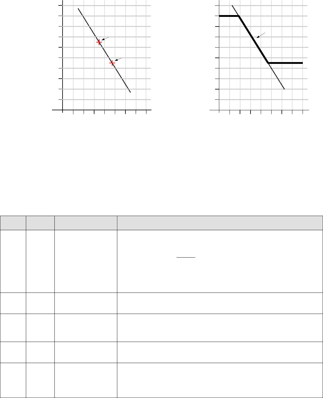
Sage Boiler Control Instruction Manual Page 37 of 56
Configuration & Tuning
Setup Menu (Continued)
Outdoor Air Temperature
Hot Water Setpoint
190
70
210
90
170
150
130
110
-20 100800 204060
230
Min Setpoint
Max Setpoint
Boiler
Setpoint
Outdoor Air Temperature
Hot Water Setpoint
190
70
210
90
170
150
130
110
-20 100800 204060
Outdoor Design
Outdoor Set Up
Set Up
Temperature
Design
Temperature
Boiler Set Up
Boiler Design
230
Outdoor Reset Graph
Energy used by the hot water heating system can be greatly reduced by adjusting (resetting) the operating temperature
setpoint as the outdoor temperature changes. Using this approach, the heat lost from the building is matched by the
heat input to the building. The control utilizes a reset curve to set the relationship between outdoor temperature and
boiler outlet temperature setpoint. The reset curve is determined from the “Set Up” and the “Design” conditions as
shown in the above graph and described by parameters 45, 46, 47 and 48:
No. Factory
Setting Range / Choices Parameter and Description
44 No No
Display Only
Outdoor Reset
Outdoor Sensor
Enables the Outside Air Temperature display and control logic:
No Outside Air Input (O+O-) is ignored.
Display Only Do Not Calculate setpoint based on outdoor
temperature, Display Outside Air Temperature
Outdoor Reset Calculate the temperature setpoint based on outdoor
temperature using a reset curve defined by Outdoor
Set Up, Boiler Set Up, Outdoor Design and boiler
Design parameters
45 55 F 40 F to 100 F Outdoor Set Up
The Outdoor Set Up temperature is the outdoor temperature at which the
Boiler Set Up temperature is supplied.
46 140 F 140 F to 180 F
Boiler Set Up
The Boiler Set Up Temperature is the starting boiler water temperature of
the reset ratio. If the building feels cool during mild outdoor conditions,
the Boiler Set Up setting should be increased.
47 30 F -20 F to 50 F Outdoor Design
The Outdoor Design Temperature is the outdoor temperature at which the
Boiler Design temperature is supplied.
48 180 F 150 F to 220 F
Boiler Design
The Boiler Design setting is the water temperature required to satisfy the
building heat loss during the Outdoor Design temperature. If the building
feels cool during cold outside conditions, the Boiler Design setting should
be increased.
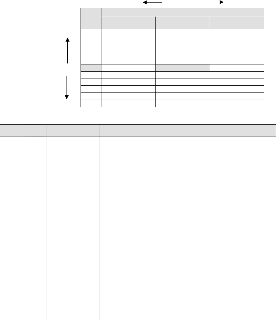
Sage Boiler Control Instruction Manual Page 38 of 56
Configuration & Tuning
Setup Menu (Continued)
Slower Response Factory Setting Faster Response
PID (I)
PID (P) ½
Repeats/Minute 1
Repeats/Minute 2
Repeats/Minute
Faster Response 61 20 10 5
41 30 15 8
36 34 17 9
30 40 20 10
25 48 24 12
Local PID Factory Setting 20 60 30 15
15 80 40 20
12 100 50 25
10 120 60 30
9 140 70 35
Slower Response 8 160 80 40
Typical Sage Boiler Control PID Gain and Integral Settings
No. Factory
Setting Range / Choices Parameter and Description
55 41 0 to 10000
Local PID P
Proportional Gain value for boiler outlet temperature sensor control Modes.
A larger gain value results in tighter, more active, PID control. Gain is the
primary PID modulation rate tuning adjustment and provides the immediate
modulation rate response.
Pick a gain based on the desired initial response. The burner modulation
rate can oscillate if the Proportional Gain is too large.
56 15 0 to 10000
Local PID I
Integral gain value for boiler outlet temperature sensor control Modes. A
smaller value makes the Integral ramp in less time (i.e., faster). Integral is a
secondary PID modulation rate tuning adjustment that ramps the output
over time (typically minutes) .
Based on the selected Local PID P, select the corresponding (from above
table) Integral value. Repeats per minute between 0.5 and 2.0 are typical.
The burner modulation rate can oscillate if the Integral time is too small.
57 0 0 to 10000
Local PID D
The Derivative gain value for boiler outlet temperature sensor control
Modes. A larger Derivative gain value produces a larger PID output
contribution proportional to the rate of change of the error (Setpoint – Boiler
Outlet Temperature). When set equal to zero it has no effect on the output.
58 20 0 to 10000 Remote PID P
Proportional Gain value for Remote System Temperature sensor control
Modes. Refer to Local PID P for explanation.
59 30 0 to 10000 Remote PID I
Integral Gain value for Remote System Temperature sensor control Modes.
Refer to Local PID I for explanation.
60 0 0 to 10000 Remote PID D
Derivative Gain value for Remote System Temperature sensor control
Modes. Refer to Local PID D for explanation.

Sage Boiler Control Instruction Manual Page 39 of 56
Configuration & Tuning
Setup Menu (Continued)
No. Factory
Setting Range / Choices Parameter and Description
61 15 0 to 10000
Mixing Valve P
Proportional Gain value for boiler Inlet temperature sensor control mode.
A larger gain value results in tighter, more active, PID control. Gain is the
primary PID modulation rate tuning adjustment and provides the
immediate mixing valve modulation response.
Pick a gain based on the desired initial response. The mixing valve can
oscillate if the Proportional Gain is too large.
62 40 0 to 10000
Mixing Valve I
Integral gain value for boiler inlet temperature sensor control mode. A
smaller value makes the Integral ramp in less time (i.e., faster). Integral is
a secondary PID modulation rate tuning adjustment that ramps the output
over time (typically minutes).
Based on the selected Mixing Valve P, select the corresponding (from
table on previous page) Integral value. The mixing valve can oscillate if
the Integral time is too small.
63 0 0 to 10000
Mixing Valve D
The Derivative gain value for boiler inlet temperature sensor control mode.
A larger Derivative gain value produces a larger PID output contribution
proportional to the rate of change of the error (Setpoint – Boiler Inlet
Temperature). When set equal to zero it has no effect on the output.
64 15 0 to 10000
Max Delta T P
Proportional Gain value for boiler differential (boiler outlet minus inlet
temperature sensor) temperature control mode. Refer to Local PID P for
explanation.
65 40 0 to 10000
Max Delta T I
Integral Gain value for boiler differential (boiler outlet minus inlet
temperature sensor) temperature control mode. Refer to Local PID I for
explanation.
66 0 0 to 10000
Max Delta T D
Derivative Gain Term for boiler differential (boiler outlet minus inlet
temperature sensor) temperature control mode. Refer to Local PID D for
explanation.

Sage Boiler Control Instruction Manual Page 40 of 56
Configuration & Tuning
Manual Mode Menu
Manual mode allows the boiler modulation rate, boiler call for head output and mixing valve position to be directly
positioned by the user. These are valuable tools for trouble shooting and setup.
No. Factory
Setting Range / Choices Parameter and Description
101 Auto Man
Auto
Boiler Man/Auto
Man: Remain in Manual Mode
Auto: Return to Boiler Mode specified by parameter/boiler conditions
Activated only when in Supervisor Mode.
102 Varies 0 to 100
Modulation Rate
Sets the modulation rate to be used for boiler when in Manual Mode
Activated only when in Supervisor Mode and Boiler Man/Auto = Man.
103 Varies On,
Off
Boiler On/Off
Sets the boiler start/stop status when in Manual Mode
No: Turn off boiler if running, otherwise remain off
Yes: Turn on boiler if off, otherwise remain on.
Activated only when in Supervisor Mode and Boiler Man/Auto = Man.
104 Man Man
Auto
Mixing Valve M/A
Man: Remain in Manual Mode
Auto: Return to Control Mode specified by parameter/boiler conditions
Activated only when in Supervisor Mode.
105 Varies 0 to 100
Mixing Valve
Sets the Mixing Valve % Open to be used for valve when in Manual Mode
Activated only when in Supervisor Mode and Mixing Valve M/A equals
Man.

Sage Boiler Control Instruction Manual Page 41 of 56
Trouble Shooting
Alarm Messages
Alarm Messages are shown one at a time in priority order. The message closest to the top of this List is displayed first.
Following messages are not shown until the higher priority message has cleared. All alarm messages are also stored in
the Fault History.
LCD Display
Alarm Message Recommended
Action Explanation
Low Water Level
O Flashing Red
Alarm Light
Manually Reset the
Low Water Cutoff Low Water Cutoff Switch
When this option is configured and a control is installed, the manual reset
low water safety relay is preventing the boiler from starting. If terminal
(LC) does not receive power and the Call For Heat output (CH) is powered
the “Low Water Level” Message is displayed.
Off Switch Turn Burner Switch
On Burner Switch is Off
Control switch is in the OFF position and is preventing the boiler from
starting. If terminal (OO) does not receive power and the Call For Heat
output (CH) is powered the “OFF Switch” Message is displayed.
Low Water Flow
O Red Alarm
Light
Ensure boiler pump is
running and boiler
water flow is
unobstructed
Low Water Flow Switch
Low water flow is preventing the boiler from starting. If terminal (WF) does
not receive power and the Call For Heat output (CH) is powered the “Low
Water Flow” Message is displayed.
Fuel Limit
O Flashing Red
Alarm Light
Manually Reset the
Fuel pressure switch Low or High Gas Pressure Switch
The low or high gas pressure switch is preventing the boiler from starting.
If terminal (GP) does not receive power and the Call For Heat output (CH)
is powered the “Fuel Limit” Message is displayed.
High Temp Limit
O Flashing Red
Alarm Light
Manually Reset the
High Temperature
Aquastat
High Limit Temperature
The high temperature limit (HL) (and operational temperature limit when
provided) aquastat is preventing a boiler start. If terminal (HL) does not
receive power and the Call For Heat output (CH) is powered the “High
Temp Limit” Message is displayed.
Low Air Flow
O Flashing Red
Alarm Light
Check combustion air
blower and air
pressure switch
settings and wiring
Low Air Flow or Blocked Vent Switch Not Made
The air flow (and blocked vent switch when provided) is preventing a boiler
start. If terminal (CA) does not receive power and the Call For Heat output
(CH) is powered the “Low Air Flow” Message is displayed.
FSG Fault
O Flashing Red
Alarm Light
Manually Reset
Required, Refer to
Flame Safeguard
Manual corrective
actions
Flame Safeguard Fault
The Flame Safeguard is preventing a boiler start. If terminal (AL) receives
power at any time, the “Flame Failure” Message is displayed.
Outlet Temp Fail
O Red Alarm
Light
Check wiring and
sensor Boiler Outlet Temperature Sensor Fail
The boiler outlet temperature sensor is not connected or is reading above
or below a valid range. When the boiler outlet sensor fails and the Outlet
Sensor mode was selected the control will transfer to Lost Sensor Blind
Mode
Inlet Temp Fail
O Red Alarm
Light
Check wiring and
sensor Boiler Inlet Temperature Sensor Fail
The boiler inlet temperature sensor is not connected or is reading above or
below a valid range. When the boiler inlet sensor fails the mixing valve
output will drive to 0% and low temperature alarm and maximum water
differential (boiler outlet minus boiler inlet) temperature hold are disabled.
OA Temp Fail
O Red Alarm
Light
Check wiring and
sensor Outside Air Temperature Sensor Fail
The outside air sensor is configured and is not connected or is reading
above or below a valid range. When the outside air sensor fails the warm
weather shutdown (WWSD) and outside air reset control logics are
disabled.
Remote Temp
Fail
O Red Alarm
Light
Check wiring and
sensor Remote System Temperature Sensor Fail
The remote system temperature sensor is configured and is not connected
or is reading above or below a valid range. If Remote System
Temperature Sensor mode was selected the control will transfer to Boiler
Outlet Sensor Mode.

Sage Boiler Control Instruction Manual Page 42 of 56
Trouble Shooting
Alarm Messages (continued)
LCD Display
Alarm Message Recommended Action Explanation
Remote Input
Fail
O Red Alarm
Light
Check wiring and
Remote System Remote Control Input Fail
The Remote Control Input is configured and is not connected or is above
or below a valid range. When the remote control input fails the following
control mode changes are taken automatically:
Selected Modes Resulting Control Mode
Remote Mod Outlet sensor and Local Setpoint
Remote Mod & Remote Sensor Remote Sensor and Local Setpoint
Remote SP Outlet Sensor and Local Setpoint
Remote SP & Remote Sensor Remote Sensor and Local Setpoint
Comm Failure
O Red Alarm
Light
Check wiring and
Remote System
Confirm each boiler has
a unique address
Communication Failure
The Modbus or Peer-To-Peer network has failed. When the Modbus
network fails the following control mode changes are taken
automatically:
Selected Modes Resulting Control Mode
Modbus Mod Outlet sensor and Local Setpoint
Modbus Mod & Remote Sensor Remote Sensor and Local Setpoint
Modbus SP Outlet Sensor and Local Setpoint
Modbus SP & Remote Sensor Remote Sensor and Local Setpoint
After a Modus communication failure, the ‘Comm Failure’ alarm is not
cleared until communication is restored and a successful writes to both
the Remote On / Off Modbus Command (00004) and Remote Firing
Rate or Remote Setpoint (40006) points have been completed, power is
cycled or the protocol parameter is changed to Peer-To-Peer and then
back to Modbus.
When a Peer-To-Peer network has failed the boilers begin operation as
stand alone boilers using the selected parameters.
After a Peer-To-Peer communication failure the ‘Comm Failure’ alarm is
not cleared until communication is restored and the boiler rejoins a
network with at least one other boiler, power is cycled or the protocol
parameter is changed to Modbus and then back to Peer-To-Peer.
Low Inlet Temp
O Red Alarm
Light
Check wiring and
sensor
Check return water
temperature. Consider
system or operational
changes to avoid low
temperature events
Low Boiler Inlet Temperature
If the boiler inlet temperature is below the Low boiler inlet temperature
setpoint, the “Low Inlet Temp” Message is displayed and the boiler inlet
temperature history is stored. See following page for additional
information on Low boiler inlet temperature history storage and retrieval.
Memory Failure
O Red Alarm
Light
Call Factory
Reset all memories in
System menu:
Clr BIT History
Clr Alarm Hist
Clr Run Time Cnt
Clr Cycle Cnt
Factory Defaults
(Factory Level
Password is required)
Memory Failure
New software has been installed in the Sage Boiler Control or a power
interruption has caused a memory failure. The Call For Heat will be
prevented until the condition is cleared.
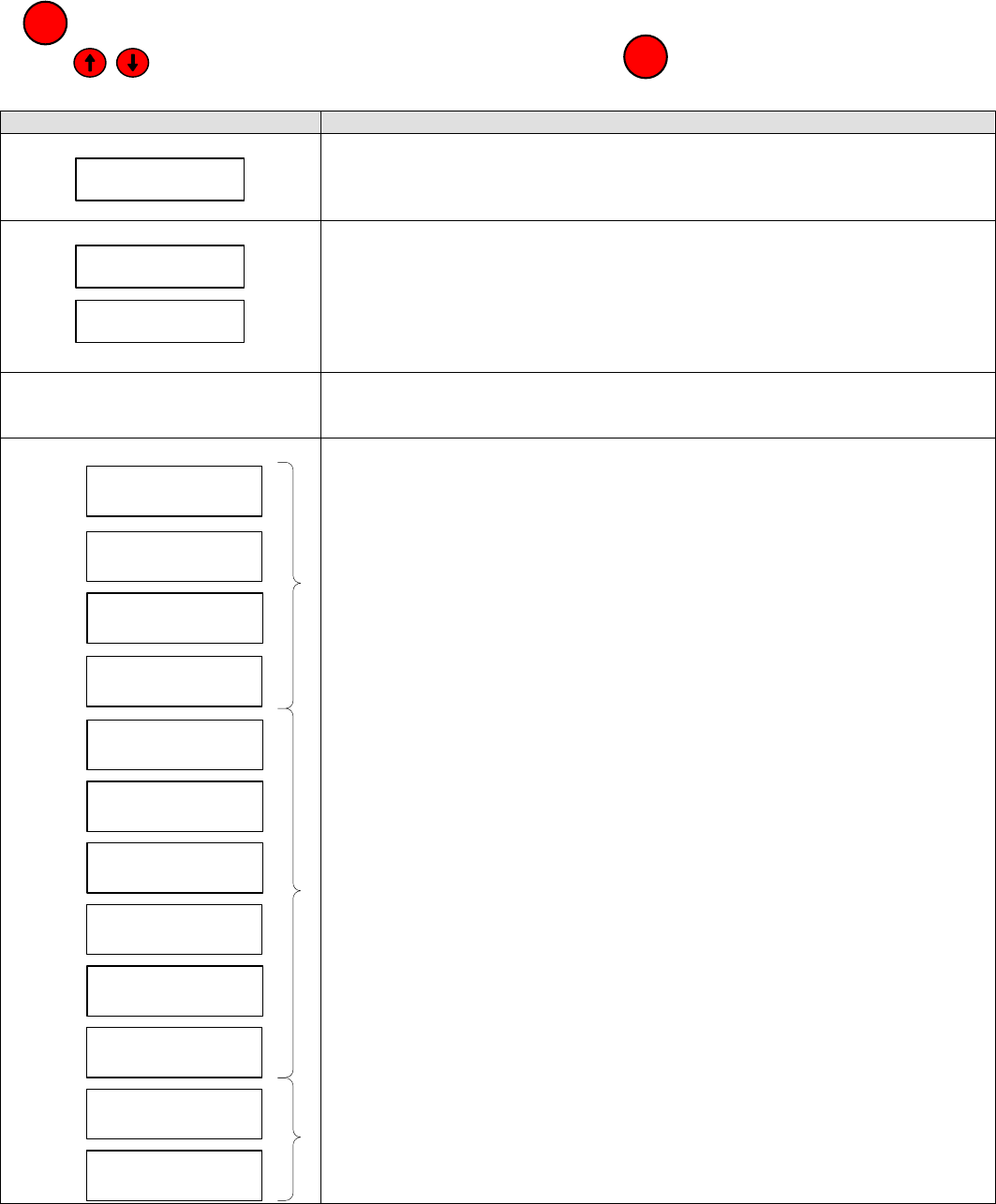
Sage Boiler Control Instruction Manual Page 43 of 56
Trouble Shooting
Diagnostic Menu
All values shown in Diagnostic Menu are for display only and cannot be adjusted by the operator. Press and hold the
key to leave the Display Mode and access the Main Menu:
Use the keys scroll down to the Diagnostic Menu and push the key:
Boiler Inlet Temperature History
Display Description
13:31 09/10/06
BOT Sensor Fail
FAULT HISTORY
The last 10 alarms are stored in memory. Use the arrow keys to scroll through
the alarms. Each alarm is displayed with the time and date it occurred.
8:45 09/10/06
Low Temp: 130F
8:45 09/10/06
Low for 1:00:02
BIT HISTORY
The last 10 Low Inlet Temperature Events are stored in memory. Each time
the boiler inlet temperature is less than the “Min In H2O Temp.” parameter, a
low temperature event is recorded. The BIT History screen automatically
toggles between the “lowest temperature for the event” and “Duration Below
Setpoint” displays and provides time and date of each event.
SYSTEM
Items provided by this menu are shown on page 43
DHW Priority
Off
Local/Remote
Off
Remote On/Off
Off
Spare Input
Off
Low Water Cutoff
Off
Burner On / Off
Off
Low Water Flow
Off
Fuel Limit
Off
Oper./High Limit
Off
Low Air Flow
Off
Fuel Energized
Off
FSG Alarm
Off
DISCRETE INPUTS
These screens provide a convenient way to trouble shoot wiring during the
installation phase. Each screen provides the status of a controller input.
These displays show the status of the corresponding Discrete Input
PLEASE NOTE
These displays provide limit string monitoring status. These inputs are only
monitored when there is a Call For Heat. Additionally, if one of these items is
‘open’, items down stream are not monitored.
These displays show the status of the corresponding Discrete Input
MENU
ENTER
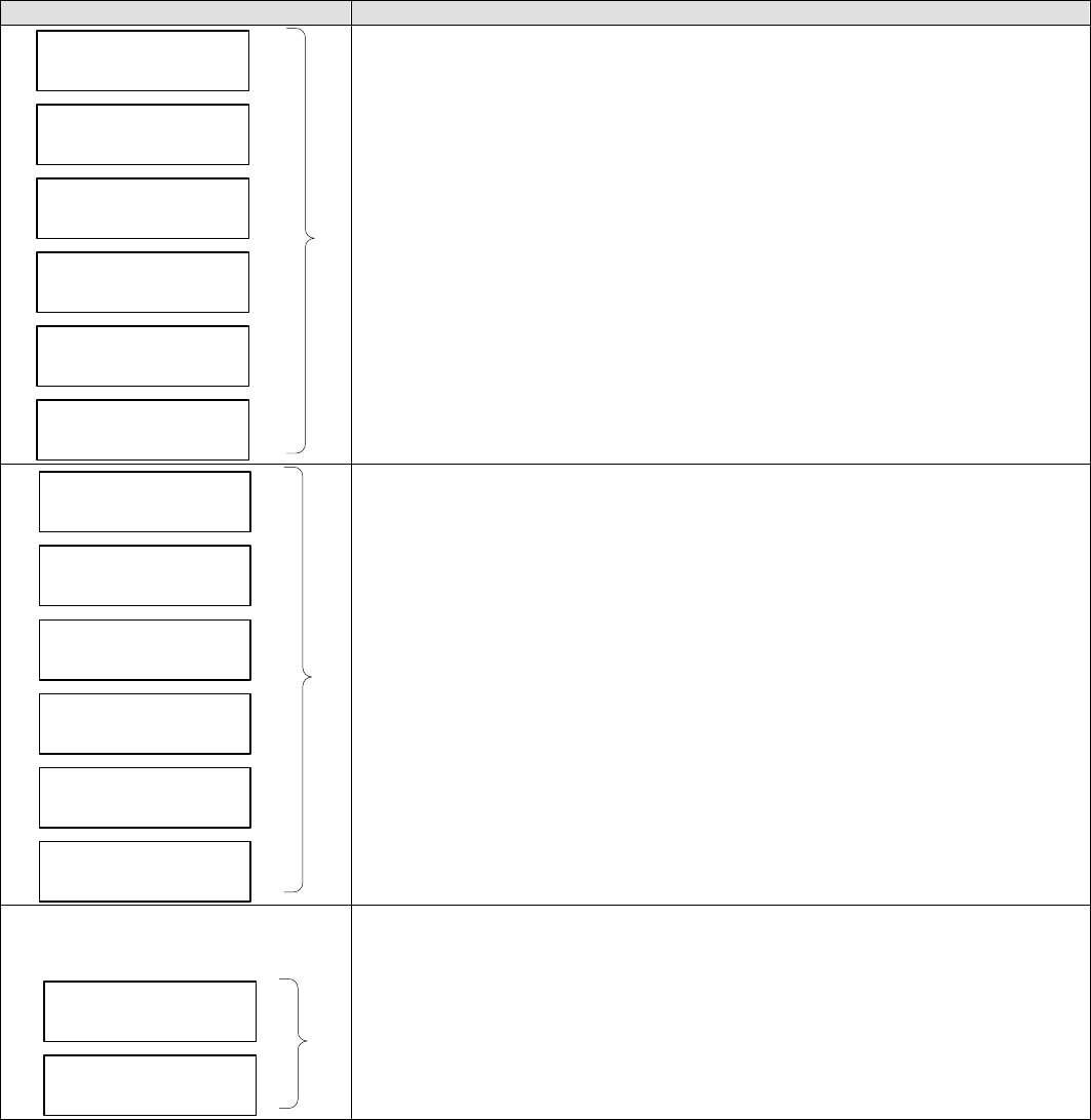
Sage Boiler Control Instruction Manual Page 44 of 56
Trouble Shooting
Diagnostic Menu (Continued)
Display Description
Call For Heat
Off
Lockout Indicator
Off
Vent Inducer
Off
Boiler Pump
Off
System Pump
Off
Spare Output
Off
DISCRETE OUTPUTS
These screens provide a convenient way to trouble shoot wiring during the
installation phase. Each screen provides the status of a controller output.
These displays show the status of the corresponding Discrete Output
Boiler Outlet
0%
Boiler Inlet
0%
Outside Air
0%
Remote System
0%
Remote Input
0%
PCB Temperature
0%
ANALOG INPUTS
These screens provide a convenient way to trouble shoot wiring during the
installation phase. Each screen provides the status of a controller analog
input.
These displays show the status of the corresponding Analog Input
Boiler Demand
0%
Mix Valve Demand
0%
ANALOG OUTPUTS
These screens provide a convenient way to trouble shoot wiring during the
installation phase. Each screen provides the status of a controller analog
Output.
These displays show the status of the corresponding Analog Output
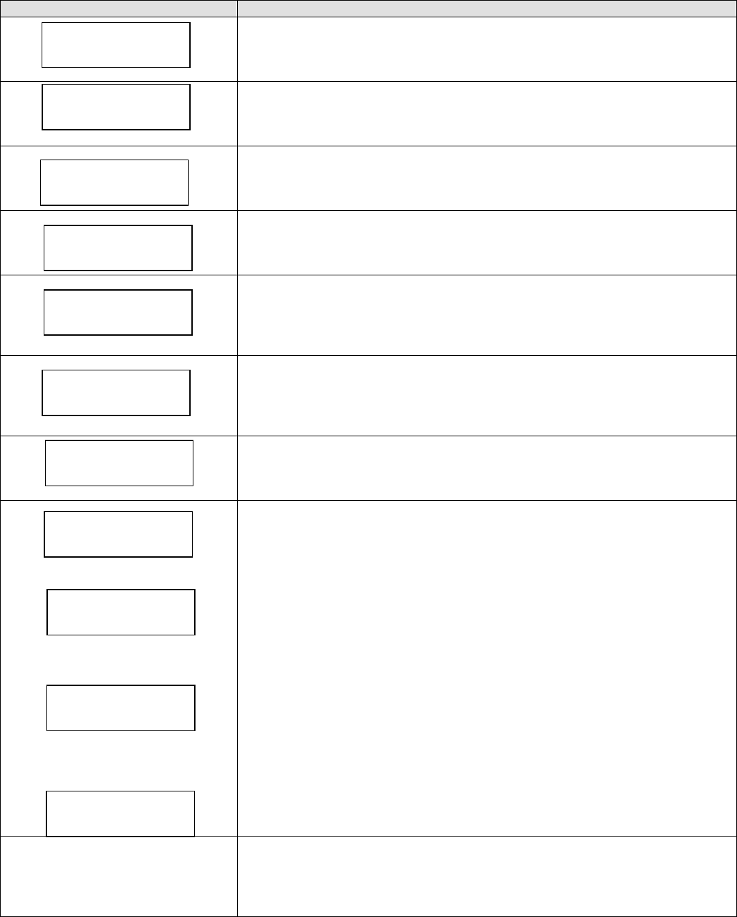
Sage Boiler Control Instruction Manual Page 45 of 56
Trouble Shooting
Diagnostic Menu (Continued)
System Menu Display Description
Software Revision
Displays current Software Revision.
PCB Board Temperature
The operating range for the control is 32 to 140 F.
Clear Boiler Inlet Temperature (BIT) Memory
No Action History remains unchanged
Yes Clears low BIT memory
Clear Alarm History Memory
No Action History Remains unchanged
Yes Clears alarms memory
Clear Boiler Run Time Hour Accumulator Memory
Boiler Run Time Hours are displayed in Display Mode as “Hours”.
No Action Hours Remain unchanged
Yes Clears accumulated hours memory
Clear Boiler Start/Stop Cycle Accumulator Memory
Boiler Start/Stop cycles are displayed in Display Mode as “Cycles”.
No Action Hours Remain unchanged
Yes Clears accumulated cycles memory
Clear User Installed Parameter Memory
No Action Currently set parameter values are unchanged
Set Sets all parameters back to their Factory Default values
Temperature Input Fine Calibration
All inputs are factory calibrated. However, it may become necessary to field
calibrate due to measuring errors resulting from long wire lengths or third party
sensor use. This is a single point calibration tool. To gain the greatest
benefit, it is recommended to calibrate as close as possible to the expected
operating temperature and measure the temperature at the sensor location.
Remote System Temperature (RST)
Outside Air Temperature (OAT)
Boiler Outlet Temperature (BOT)
Boiler Inlet Temperature (BIT)
Calibration Procedure:
1. Select sensor that requires field calibration
2. Run boiler to rated condition
3. Enter the Actual RST, OAT, BOT and BIT
4. Display will flash back to the default (Note Calibration number does
not remain on screen)
5. Calibration is complete. A one point calibration offset is calculated and
applied.
Param Code
Parameter Code
This number represents “Network Relevant” parameters. It can be used to
ensure that these parameters are identical when establishing a Peer-To-Peer
network
.
Software Rev.
S 3.24
PCB Temperature
70 F
Actual RST
32 F
Actual OAT
-40 F
Actual BOT
32 F
Actual BIT
32 F
Clr BIT Hist
No Action
Clr Cycle Cnt
No Action
Factory Defaults
No Action
Clr Alarm Hist
No Action
Clr Run Time Cnt
No Action

Sage Boiler Control Instruction Manual Page 46 of 56
Trouble Shooting
Sensor Resistance Chart
Sensor Temperature vs. Resistance
Water Temperature Ohms of Water Temperature Ohms of Water Temperature Ohms of
°C °F Resistance °C °F Resistance °C °F Resistance
-22 -8 110,460 14 58 16,126 51 124 3,453
-21 -6 103,486 16 60 15,313 52 126 3,311
-20 -4 96,999 17 62 14,546 53 128 3,176
-19 -2 90,962 18 64 13,822 73 164 1,565
-18 0 85,340 19 66 13,139 74 166 1,508
-17 2 80,103 20 68 12,493 76 168 1,453
-16 4 75,222 21 70 11,884 77 170 1,401
-14 6 70,670 22 72 11,307 78 172 1,350
-13 8 66,424 23 74 10,762 79 174 1,302
-12 10 62,460 24 76 10,247 80 176 1,256
-11 12 58,759 26 78 9,760 81 178 1,212
-10 14 55,301 27 80 9,298 82 180 1,169
-9 16 52,069 28 82 8,862 83 182 1,129
-8 18 49,047 29 84 8,448 84 184 1,089
-7 20 46,220 30 86 8,056 86 186 1,052
-6 22 43,574 31 88 7,685 87 188 1,016
-4 24 41,097 32 90 7,333 88 190 981.2
-3 26 38,776 33 92 6,999 89 192 947.9
-2 28 36,601 34 94 6,682 90 194 915.9
-1 30 34,562 36 96 6,382 91 196 885.2
0 32 32,650 37 98 6,097 92 198 855.7
1 34 30,856 38 100 5,826 93 200 827.3
2 36 29,171 39 102 5,569 94 202 800.1
3 38 27,590 40 104 5,325 96 204 773.8
4 40 26,104 41 106 5,093 97 206 748.6
6 42 24,707 42 108 4,872 98 208 724.3
7 44 23,394 43 110 4,663 99 210 700.9
8 46 22,159 44 112 4,463 100 212 678.4
9 48 20,997 46 114 4,273 101 214 656.8
10 50 19,903 47 116 4,093 102 216 635.9
11 52 18,873 48 118 3,921 103 218 615.8
12 54 17,902 49 120 3,757 104 220 596.5
13 56 16,988 50 122 3,601

Sage Boiler Control Instruction Manual Page 47 of 56
Trouble Shooting
Security Menu
Passwords
There are three Access Levels in the system; Basic, Supervisor, and Factory.
• At the BASIC Access Level, the user can view many parameters, but is only allowed to edit a small sub-set of
the parameters that are visible.
• At the SUPERVISOR Access Level, the user can view and edit most parameters that are visible. Note: not all
parameters will be visible at the Supervisor Access Level.
• At the FACTORY Access Level, all relevant internal parameters in the system will be visible and programmable.
The Basic Access Level is the access level at power-up if the system password parameter is not equal to zero. The
Supervisor Access Level is the access level at power-up if the system password parameter is equal to zero. If the
system password is non-zero, the Supervisor Access Level may be reached by entering the correct password in the
Enter Password parameter.
The Factory Access Level can be reached by entering the factory password in the Enter Password parameter and
holding the Enter key for at least two seconds when accepting the value entered. The display will jump to the Access
Level parameter menu when the system has entered the Factory Access Level. Note that the Access Level parameters
value will indicate "Supervisor".
To exit either of the privileged access levels (Factory and Supervisor), change the value of the Access Level parameter
from "Supervisor" to "Basic". Also, if no key is pressed for ~ 1 hour, the access level will automatically revert to Basic.
No. Factory
Setting Range / Choices Parameter and Description
Basic
Supervisor
Access Level
Basic: Select Basic Level Access to parameters/variables
Supervisor: Select Password Level Access to parameters/variables
0 to 9999
Enter Password
Allows user to enter password to gain access to both Supervisor Access
and Factory Access Levels.
Factory
Password
is 86 0 to 9999
Set Password
Holds the user-defined password for the boiler. A password = 0 means
no password protection. Access Level will default to Supervisor Level at
power-up.

Sage Boiler Control Instruction Manual Page 48 of 56
Specifications
General
Mechanical:
Panel Assembly: 8 inches wide x 6 inches tall
Message Display: 2 x 16 Character, 8.06 mm characters
Environmental:
Operating Temp: 32 to 140 F (0 to 60 C)
Storage Temp: -20 to 150 F (-28 to 65 C)
Humidity Limits: 15 to 95% (non-condensing)
Front Panel: NEMA 1
Electrical:
Power Supply: 24Vac
Note: All 24Vac Inputs must be connected to the same phase as (PR)
Internal Power Consumption: 8 VA max, 24Vac (+/- 15%), and 6 VA max,
12Vac 0.5A for LO, VI, BP, SP and SO
Discrete Inputs:
Terminal Description Rating
DP Domestic Hot Water Priority (DHWP) 12 Vdc / 1 mA
LR Local / Remote 12 Vdc / 1 mA
RO Remote On / Off (Enable) 12 Vdc / 1 mA
SI Spare Input (Programmable) 12 Vdc / 1 mA
LC Low Water Cutoff Switch 24 Vac / 1mA
OO Burner On / Off Switch 24 Vac / 1mA
WF Low Water Flow 24 Vac / 1mA
GP High and Low Gas Pressure Switches 24 Vac / 1mA
HL Operating or High Limit 24 Vac / 1mA
CA Low Combustion Air Flow 24 Vac / 1mA
CS Fuel Valve Energized 24 Vac / 1mA
AL Flame Safeguard Alarm 24 Vac / 1mA
Discrete Outputs:
Terminal Description Rating
CH Call For Heat (CFH) 24 Vac / 10A
LO Lockout Indicator 12 Vdc / 100mA
VI Spare Output 12 Vdc / 100mA
BP Boiler Pump 12 Vdc / 100mA
SP System Pump 12 Vdc / 100mA
SO Spare Output (Programmable) 12 Vdc / 100mA
Analog Inputs:
Terminal Description Rating
BO Boiler Outlet Water Temperature 10k Thermister, 5Vdc, 5 mA max load
BI Boiler Inlet Water Temperature 10k Thermister, 5Vdc, 5 mA max load
O+
O - Outside Air Temperature 10k Thermister, 5Vdc, 5 mA max load
R+
R - Remote System Temperature 10k Thermister, 5Vdc, 5 mA max load
C+
C - Remote Modulation Rate or Remote Setpoint 0-10 Vdc (~100K ohm impedance)
1Vdc = 0%, 9Vdc = 100%
Analog Outputs:
Terminal Description Rating
P+
P- 0 – 100 % Duty Cycle, 0V – Off, ~10V - On
V+
V-
Modulation Rate Output to Mod Motor 0 – 10 V, 5 mA max
MS
MR Mixing Valve Output 4-20mA
4 mA = 0 % Open, 20 mA = 100% Open

Sage Boiler Control Instruction Manual Page 49 of 56
Specifications
General (Continued)
Real Time Clock: Battery Backed, 2 yrs without AC Power
Communications: Programming - ISP Port
Boiler Peer to Peer – RS485, RTU
Time and Date Battery:
The battery is only used to power the time of day and date clock chip when the 24 Vac power
is removed from the Sage Boiler Control. When new, the battery can power the clock for
approximately 2 years with 24 Vac power removed. The clock battery has a shelf life of
approximately 6 years (without ac applied). Sage Boiler Control configuration and user data
are stored in non-volatile EEPROM. This battery is NOT used to retain this memory.
The battery is located at the back of the Sage Boiler Control for easy replacement.
Component Description Repair Part Number
1. Sage Boiler Control Assembly (un-programmed).......................................................................................102106-01
Individual boiler operating and modulation rate control and modulating lead-lag controller.
Built to UL and CSA standards.
2. Replacement Fuse Busman GMC-5A
3. Immersion Temperature Sensor .................................................................................................................101935-01
½” NPT 10K OHM @ 25C, NTC Thermistor Type, Resistance Ratio R0/R50 = 9.07 temperature
sensor for measuring water temperature in supply manifold, return manifold or system header.
4. Outdoor Temperature Sensor.................................................................................................................801SOL0012
10K OHM @ 25C, NTC Thermistor Type, Resistance Ratio R0/R50 = 9.07 outdoor air temperature
sensor with weather proof box and protective sleeve.
For use in outdoor reset applications.
5. Wire Harness (Sage to Q7800H) .........................................................................................................101976-01
6. Q7800H Flame Safeguard Sub Base...................................................................................................101182-01
7. Sage Control (programmed).................................................................................................................102436-01
8.. SBC Parts Carton, MPC [includes MPC Sensor J-Box, Snap bushing (for Sensor J-Box) and MPC
Sensor J-Box Cover (with holes)].........................................................................................................101977-01

Sage Boiler Control Instruction Manual Page 50 of 56
Appendix A
Parameter Summary
Network
Relevant* Parameter Range / Choices Factory
Setting Security
Level** Page
Boiler Configuration Menu
Update Display Units Deg F / Deg C Deg F Basic 31
Yes Boiler Pump None / On Always / Purge / On Lead None Supervisor 31
Update If Purge, set Pump Prepurge 0 to 600 seconds 15 Supervisor 31
Update Postpurge Delta 0 to 20 F 5 Supervisor 31
- Inlet Sensor Yes / No Yes Supervisor 31
- Mixing Valve Yes / No No Supervisor 31
Update Set Time/Date hour : minute month / day / year Basic 31
Update Fuel Limit Yes / No No Factory 31
Update Spare Input Off / Sys Pump Feedback / Low Fire Off Supervisor 31
Update Spare Output Off / CAD / Sys Pump BU / Soft Alarm Off Supervisor 31
System Configuration Menu
Yes DHWP Off / Isolated Demand / Shared Demand Off Basic 32
Yes Remote control No / Remote SP / Modbus SP /
Remote Mod / Modbus Mod No Supervisor 32
- Remote 1 volts = 60 F to150 F 140 Supervisor 32
- Remote 9 volts = 150 F to 230 F 220 Supervisor 32
Yes Remote Sensor No / Display Only / Control No Supervisor 32
Yes System Pump Yes / No No Supervisor 32
Update LWC or CAD Yes / No No Supervisor 32
Update Alarm Message Low Water level Supervisor 32
Setup Menu
Yes WWSD Off / WWSD of Boiler / WWSD of Sys
Pump / Both Off Basic 33
Yes LL Start Trigger 50 to100% of Modulation Rate 90 Supervisor 33
Yes LL Stop Trigger 0 to 50% of Modulation Rate 25 Supervisor 33
Yes Boiler On Delay 0 to 900 seconds 5 Supervisor 33
Yes Boiler Off Delay 0 to 900 seconds 5 Supervisor 33
Yes %FR On Delay 1 to 30 minutes 20 Factory 33
Yes %FR Off Delay 1 to 30 minutes 20 Factory 33
Yes High Fire Limit 40 - 100 % Modulation Rate 100 Supervisor 33
Yes Deg/Min Hold Off 1 - 10 Degrees / Minute 1 Factory 33
Yes Cutback Setpoint 100 F - 240 F 220 Factory 33
Yes Net Start Dwell 16 to 420 Seconds 120 Factory 34
Yes Limit Fault Time 3 to 120 Seconds 5 Factory 34
Yes Rotation Enable / Disable Disable Basic 34
Yes Rotation After 8 to720 hours 48 Basic 34
Yes Outdoor Sensor No / Display Only / Outdoor Reset No Basic 35
Yes Outdoor Set Up 40 F to 100 F 55 Basic 35
Yes Boiler Set Up 80 F to 180 F 140 Basic 35
Yes Outdoor Design - 20 F to 50F 30 Basic 35
Yes Boiler Design 80 F to 220 F 180 Basic 35
∗ Parameters identified by “Yes” under the “Network Relevant” column must be configured identically on all boilers.
Unexpected boiler behavior may result if these parameter values differ among boilers on the network. Once
communications is established between all boilers in a system, changes to parameters identified as “Yes” or
“Update” under the “Network Relevant” column at the keypad of any boiler will update that parameter in all boilers.
** To change your current security level refer to page 46 Security Level operations.

Sage Boiler Control Instruction Manual Page 51 of 56
Appendix A
Parameter Summary (continued)
Network
Relevant* Parameter Range / Choices Factory
Setting Security
Level** Page
Setup Menu (continued)
- Blower Spd High 0 to100 % of full scale 100 Factory 34
- Blower Spd Low 0 to100 % of full scale 0 Factory 34
- Low Fire Spd 0 to100 % Modulation Rate 0 Factory 34
- Fan Purge Spd 0 to100 % Modulation Rate 100 Factory 34
Yes Low Fire Hold 0 to 1200 sec 0 Factory 34
Yes Post Purge Time 0 to 600 sec 0 Factory 34
Yes Local PID P 0-10000 20 Supervisor 36
Yes Local PID I 0-10000 30 Supervisor 36
Yes Local PID D 0-10000 0 Supervisor 36
Yes Remote PID P 0-10000 20 Supervisor 36
Yes Remote PID I 0-10000 30
Supervisor 36
Yes Remote PID D 0-10000 0
Supervisor 36
Yes Mixing Valve P 0-10000 15 Supervisor 37
Yes Mixing Valve I 0-10000 40 Supervisor 37
Yes Mixing Valve D 0-10000 0 Supervisor 37
Yes Mixing Delta T P 0-10000 15 Supervisor 37
Yes Mixing Delta T I 0-10000 40 Supervisor 37
Yes Mixing Delta T D 0-10000 0 Supervisor 37
Setpoint Menu
Yes Operational Setpoint 60 F to 230 F 180 Basic 19
Yes On point 0 F to – 99 F -5 Basic 19
Yes Off Point 0 F to 99 F 5 Basic 19
Yes High Temp Stop 60 F to 230 F 200 Basic 19
Yes DHWP setpoint 140 F to 230 F 180 Basic 19
Yes WWSD setpoint 40 F 90 F 70 Basic 19
Yes Max SP 140 F to 230 F 230 Supervisor 19
Yes Min SP 60 F to 230 F 140 Supervisor 19
Yes Min BIT 110 F to 235 F 120 Factory 19
Update Min Inlet H2O Temp 110 F to 180 F 130 Supervisor 19
Update Max H2O Delta T 20F to 50 F 50 Supervisor 19
Update Max Delta T Hold 20F to 50 F 40 Supervisor 19
Communication Menu
- Protocol Peer to Peer / Modbus Peer to Peer Supervisor 27
- Modbus Address 1-247 1
Supervisor 27
- Baud Rate 9.6 / 19.2 / 38.4 19.2 Supervisor 27
- Parity Odd / Even / None None Supervisor 27
- Timeout 1 Second to 120 Seconds 30 Supervisor 27
- Boiler Address 1 to 8 1 Supervisor 27
∗ Parameters identified by “Yes” under the “Network Relevant” column must be configured identically on all boilers.
Unexpected boiler behavior may result if these parameter values differ among boilers on the network. Once
communications is established between all boilers in a system, changes to parameters identified as “Yes” or
“Update” under the “Network Relevant” column at the keypad of any boiler will update that parameter in all boilers.
** To change your current security level refer to page 46 Security Level operations.

Sage Boiler Control Instruction Manual Page 52 of 56
Appendix B
Customer Parameter Worksheet
Parameter Range / Choices Units
Boiler Configuration Menu
Display Units Circle one: Deg F Deg C
Boiler Pump Circle one: None On Always Purge On Lead
Pump Prepurge Seconds
Postpurge Delta F
Inlet Sensor Circle one: Yes No
Mixing Valve Circle one: Yes No
Spare Input Circle one: Off Low Fire Sys Pump Feedback
Spare Output Circle one: Off CAD Soft Alarm Sys Pump BU
System Configuration Menu
DHWP Circle one: Off Isolated Demand Shared Demand
Remote control Circle one: No Remote SP Modbus SP
Remote Mod Modbus Mod
Remote 1 volts = F
Remote 9 volts = F
Remote Sensor Circle one: No Display Only Control
System Pump Circle one: Yes No
LWC or CAD Circle one: Yes No
Alarm Message
Setup Menu
WWSD Circle one: Off WWSD of Boiler WWSD of Sys Pump Both
LL Start Trigger %
LL Stop Trigger %
Boiler On Delay Seconds
Boiler Off Delay Seconds
High Fire Limit %
Rotation Circle one: Enable Disable
Rotation After Hours
Outdoor Sensor Circle one: No Display Only Outdoor Reset
Outdoor Set Up F
Boiler Set Up F
Outdoor Design F
Boiler Design F
Local PID P
Local PID I
Local PID D
Remote PID P
Remote PID I
Remote PID D
Mixing Valve P
Mixing Valve I
Mixing Valve D
Mixing Delta T P
Mixing Delta T I
Mixing Delta T D

Sage Boiler Control Instruction Manual Page 53 of 56
Appendix B
Customer Parameter Worksheet (continued)
Parameter Range / Choices Units
Setpoint Menu
Operational Setpoint F
On point F
Off Point F
High Temp Stop F
DHWP setpoint F
WWSD setpoint F
Max SP F
Min SP F
Min Inlet H2O Temp F
Max H2O Delta T F
Max Delta T Hold F
Communication Menu
Protocol Circle one: Peer to Peer Modbus
Modbus Address
Baud Rate Circle one: 9.6 19.2 38.4
Parity Circle one: Odd Even None
Timeout Seconds
Boiler Address

Sage Boiler Control Instruction Manual Page 54 of 56
SERVICE RECORD
DATE SERVICE PERFORMED
Sage Boiler Control Instruction Manual Page 55 of 56
THIS PAGE LEFT BLANK INTENTIONALLY
Sage Boiler Control Instruction Manual Page 56 of 56
