Burnham Series 5B Boiler Installation Operating Instructions
2015-06-08
: Burnham Burnham-Series-5B-Boiler-Installation-Operating-Instructions-738082 burnham-series-5b-boiler-installation-operating-instructions-738082 burnham pdf
Open the PDF directly: View PDF ![]() .
.
Page Count: 112 [warning: Documents this large are best viewed by clicking the View PDF Link!]
1
DNAGNITAREPO,NOITALLATSNI
ROFSNOITCURTSNIECIVRES
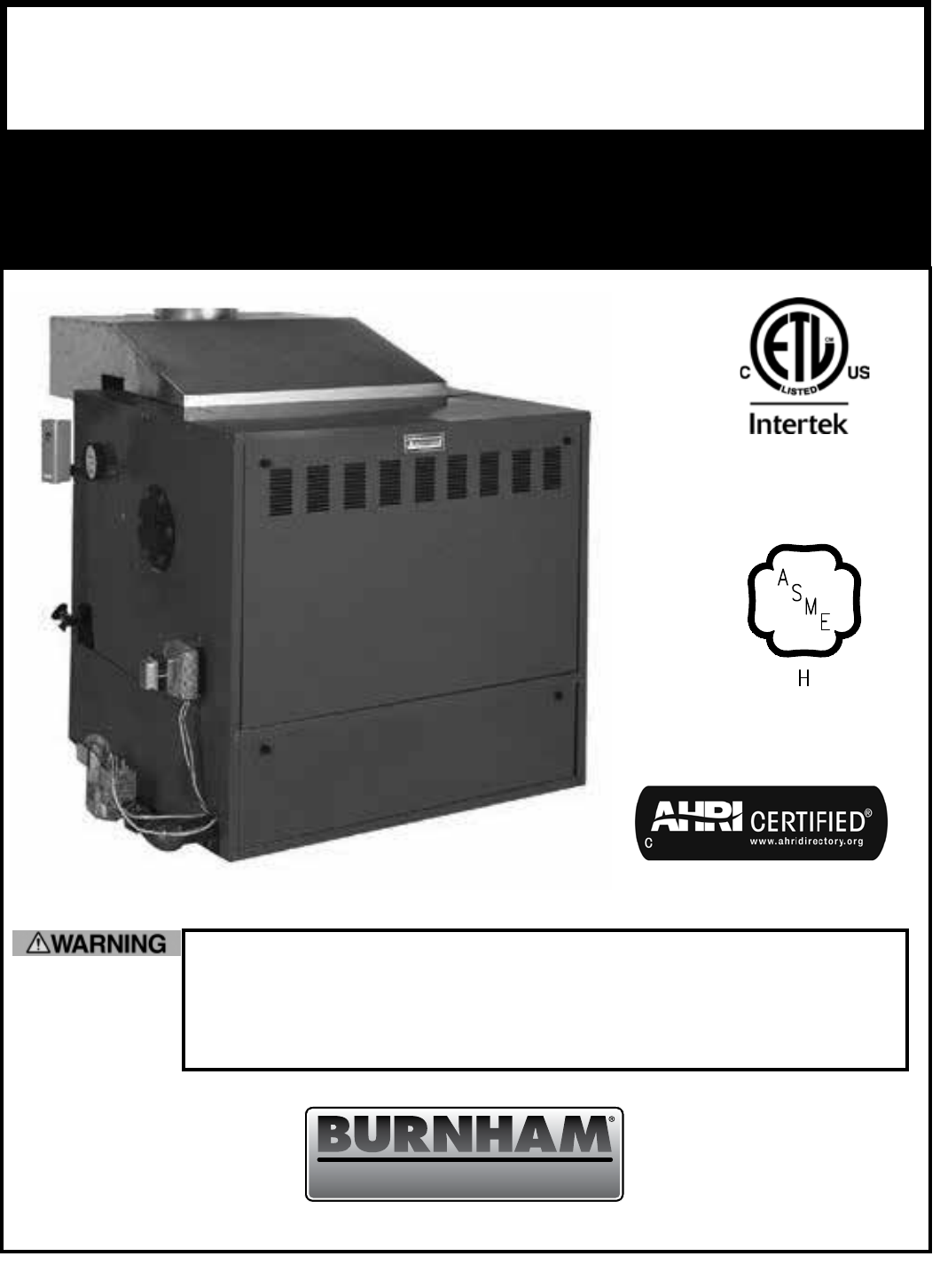
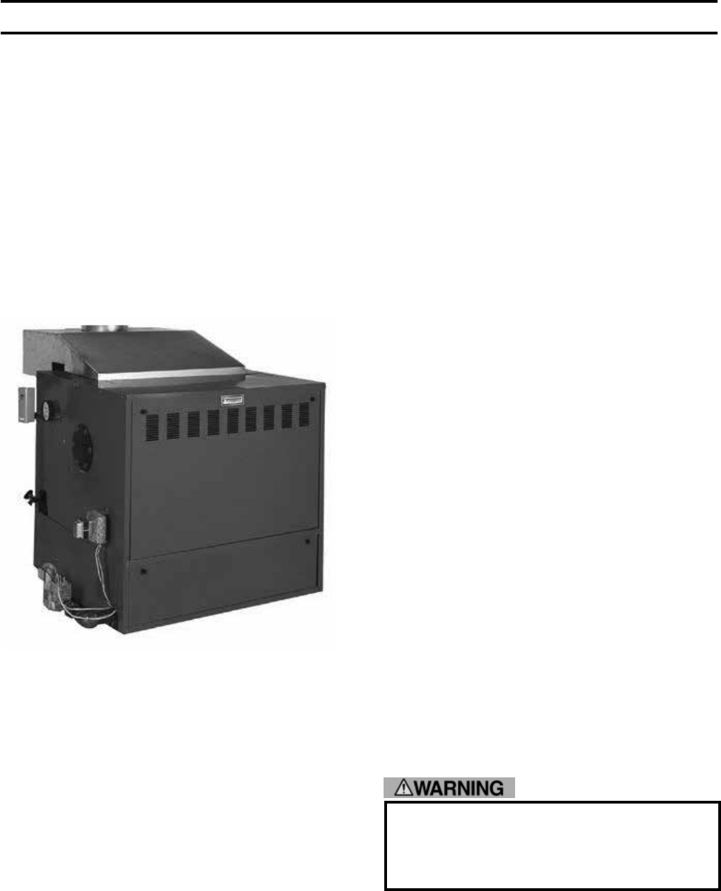
B5SEIRES
DERIF-SAG
RELIOB
8141302R18 - 1/15 PRICE - $5.00
Commercial Boilers
www.burnhamcommercial.com
3050579
This manual must only be used by a qualied heating installer/service technician.
BEFORE installing, read all instructions in this manual and all other information
shipped with the boiler. Post all instructions and manuals near the boiler for
reference by service personnel. Perform steps in the order given. Failure to comply
could result in severe personal injury, death or substantial property damage.

2
The following dened terms are used throughout this manual to bring attention to the presence of hazards of various
risk levels or to important information concerning the life of the product.
Indicates an imminently hazardous situation
which, if not avoided, will result in death, serious
injury or substantial property damage.
Indicates a potentially hazardous situation which,
if not avoided, may result in moderate or minor
injury or property damage.
Indicates a potentially hazardous situation which,
if not avoided, could result in death, serious injury
or substantial property damage.
Indicates special instructions on installation,
operation, or maintenance which are important
but not related to personal injury hazards.
Hazard definitions
THIS BOILER HAS A LIMITED WARRANTY, A COPY OF WHICH IS PRINTED ON THE BACK OF THIS MANUAL.
It is the responsibility of the installing contractor to see that all controls are correctly installed and are
operating properly when the installation is complete. The warranty for this boiler is valid only if the boiler
has been installed, maintained and operated in accordance with these instructions.
DO NOT store or use gasoline or other ammable vapors or liquids in the vicinity of this or any other
appliance.
If you smell gas or fuel oil vapors, do not try to operate the burner/boiler system. Do not touch any
electrical switch or use any phone in the building. Immediately call the gas or oil supplier from a remotely
located phone.
Burner/boiler systems produce steam or hot water in a pressurized vessel by mixing extremely ammable
gaseous, liquid or solid fuels with air to produce combustion and very hot products of combustion.
Explosions, res severe personal injury, death and/or property damage will result from improper, careless
or inadequate installation, operation or maintenance of fuel-burning and boiler equipment.
IMPORTANT INFORMATION -
READ and save these instructions for reference

3
Improper installation, adjustment, alteration, service or maintenance can cause property damage, personal
injury or loss of life. Failure to follow all instructions in the proper order can cause personal injury or
death. Read and understand all instructions, including all those contained in component manufacturers
manuals which are provided with the appliance before installing, starting-up, operating, maintaining or
servicing this appliance. Keep this manual and literature in legible condition and posted near appliance
for reference by owner and service technician.
This boiler requires regular maintenance and service to operate safely. Follow the instructions contained
in this manual.
Installation, maintenance, and service must be performed only by an experienced, skilled and knowledgeable
installer or service agency.
All heating systems should be designed by competent contractors and only persons knowledgeable in
the layout and installation of hydronic heating systems should attempt installation of any boiler.
It is the responsibility of the installing contractor to see that all controls are correctly installed and are
operating properly when the installation is completed.
Installation is not complete unless a pressure relief valve is installed into the specied tapping on the
supply manifold located on top and at rear of appliance - See Section III, Paragraph 33, ‘e’ of this manual
for details.
This boiler is NOT suitable for installation on combustible ooring.
Do not tamper with or alter the boiler or controls. Retain your contractor or a competent serviceman to
assure that the unit is properly adjusted and maintained.
Clean boiler at least once a year - preferably at the start of the heating season to remove soot and scale.
The inside of the combustion chamber should also be cleaned and inspected at the same time.
Have Burner and Controls checked at least once a year or as may be necessitated. Do not operate
unit with jumpered or absent controls or safety devices. Do not operate unit if any control, switch,
component, or device has been subject to water.
4
Appliance materials of construction, products of combustion and the fuel contain alumina, silica, heavy
metals, carbon monoxide, nitrogen oxides, aldehydes and/or other toxic or harmful substances which
can cause death or serious injury and which are known to the state of California to cause cancer, birth
defects and other reproductive harm. Always use proper safety clothing, respirators and equipment when
servicing or working nearby the appliance.
This boiler contains very hot water under high pressure. Do not unscrew any pipe ttings nor attempt
to disconnect any components of this boiler without positively assuring the water is cool and has no
pressure. Always wear protective clothing and equipment when installing, starting up or servicing this
boiler to prevent scald injuries. Do not rely on the pressure and temperature gauges to determine the
temperature and pressure of the boiler. This boiler contains components which become very hot when
the boiler is operating. Do not touch any components unless they are cool.
This appliance must be properly vented and connected to an approved vent system in good condition.
Do not operate boiler with the absence of an approved vent system.
This boiler needs fresh air for safe operation and must be installed so there are provisions for adequate
combustion and ventilation air.
The interior of the venting and air intake systems must be inspected and cleaned before the start of the
heating season and should be inspected periodically throughout the heating season for any obstructions.
Clean and unobstructed venting and air intake systems are necessary to allow noxious fumes that could
cause injury or loss of life to vent safely and will contribute toward maintaining the boiler’s efciency.
This boiler is supplied with controls which may cause the boiler to shut down and not re-start without
service. If damage due to frozen pipes is a possibility, the heating system should not be left unattended in
cold weather; or appropriate safeguards and alarms should be installed on the heating system to prevent
damage if the boiler is inoperative.
This boiler is designed to burn natural and/or LP gas only. Do not use gasoline, crankcase drainings, or
any oil containing gasoline. Never burn garbage or paper in this boiler. Do not convert to any solid fuel
(i.e. wood, coal). All ammable debris, rags, paper, wood scraps, etc., should be kept clear of the boiler
at all times. Keep the boiler area clean and free of re hazards.
Float type low water cutoff devices require annual inspection and maintenance. Refer to instructions in
Section V, Paragraph 7 for inspection and cleaning instructions.
Series 5B cast iron boilers are designed, built, marked and tested in accordance with the ASME Boiler and
Pressure Vessel Code, Section IV, Heating Boilers. An ASME Data Label is factory applied to each Series 5B
jacket, which indicates the boiler Maximum Allowable Working Pressure (MAWP). Each cast iron section is
permanently marked with the MAWP listed on the boiler’s ASME Data Label. Those values for the Series 5B
are as follows:
MAWP, Water - 50 PSI
MAWP, Steam - 15 PSI

5
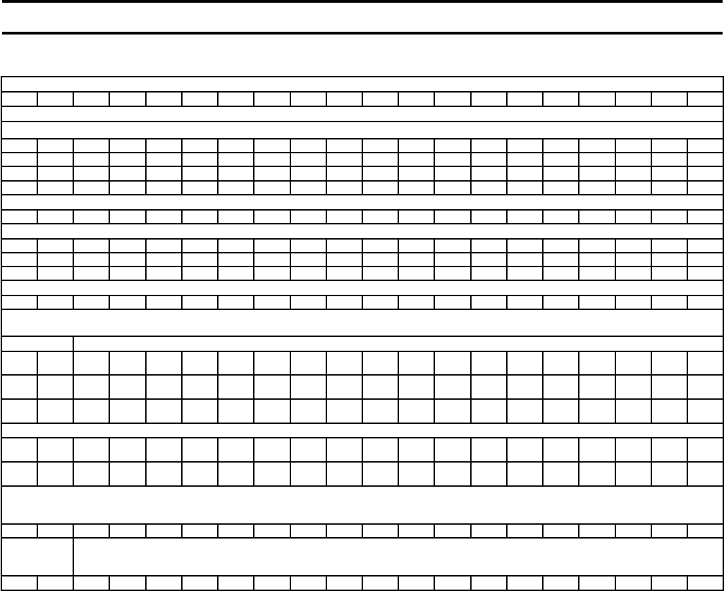
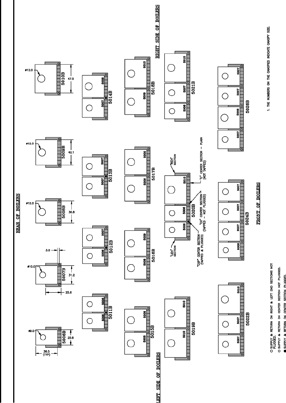
BOILER SIZE
5006B 5007B 5008B 5009B 5010B 5011B 5012B 5013B 5014B 5015B 5016B 5017B 5018B 5019B 5020B 5021B 5022B 5024B 5026B
(1)
LEH 1111111111111111111
(1)
REH 1111111111111111111
(1)
C 45678891011 12 13 14 15 16 16 17 18 19 21
(2)
CX --- --- --- --- --- --- --- --- --- 1 1 1 1 1 1 2 2 3 3
(3)
CXP --- --- --- --- --- 1 1 1 1 --- --- --- --- --- 1 --- --- --- ---
(1) Section Marking Cast on Section
(2) “C” Cast on Section - When supply and return connections are tapped, section is paint stencilled “CX”
(3) “C” Cast on Section - When supply and return connections are tapped and plugged, section is paint stencilled “CXP”
CARTONS, PACKAGES, OR BUNDLES
1Base-Burner-Manifold Assembly (By Gas and By Pilot System) - One Left & One Right Req’d on 5015B and Larger Boilers
COMPLETE 1
6
1
7
1
8
1
9
1
10
1
11
1
12
1
13
1
14 --- --- --- --- --- --- --- --- ---
L. SUB-BASE --- --- --- --- --- --- --- --- ---
L
1S
15
L
1S
16
L
1S
17
L
1S
18
L
1S
19
L
1S
20
L
1S
21
L
1S
22
L
1S
24
L
1S
26
R. SUB-BASE --- --- --- --- --- --- --- --- ---
R
1S
8
R
1S
9
R
1S
9
R
1S
10
R
1S
10
R
1S
10
R
1S
10
R
1S
10
R
1S
13
R
1S
13
2Tie Rod Bundle(s) 4 Sizes - One to Five Per Boiler
22” --- --- 1 --- --- --- --- --- --- --- --- --- --- --- --- --- --- --- ---
27” --- --- 1 2 1 --- --- --- 2 1 --- --- --- --- 1 --- --- --- 2
37” 1 --- --- --- 1 2 1 --- 1 2 3 2 1 --- 3 4 3 1 ---
42” --- 1 --- --- --- --- 1 2 --- --- -- 1 2 3 --- --- 1 3 3
2 A Draw-up Rod Bundle(s) 3 Sizes - One to Three Per Boiler
37¾” --- --- --- --- --- 2 2 1 1 --- --- --- --- --- --- --- --- --- ---
49¼” 1 1 --- --- --- --- --- 1 1 2 2 1 1 1 --- --- --- 3 2
67¼” --- --- 1 1 1 --- --- --- --- --- --- 1 1 1 2 2 2 --- 1
3 A Boiler Assembly Carton(s) 6 Sizes - One to Five Per Boiler
3A6 1 --- --- --- --- 1 --- --- --- --- 1 --- --- --- --- 1 --- --- ---
3A7 --- 1 --- --- --- --- 1 --- --- --- --- 1 --- --- --- --- 1 --- ---
3A8 --- --- 1 --- --- --- --- 1 --- --- --- --- 1 --- --- --- --- --- 1
3A9 --- --- --- 1 --- --- --- --- 1 --- --- --- --- 1 --- --- --- 1 1
3A10 --- --- --- --- 1 --- --- --- --- 1 --- --- --- --- 1 --- --- --- ---
3AM --- --- --- --- --- 1 1 1 1 1 2 2 2 2 2 3 3 3 3
4Boiler Sealing Carton(s) 5 Sizes - One to Three Per Boiler
06 1 --- --- --- --- 2 1 --- --- --- --- --- --- --- 2 --- 1 --- ---
07 --- 1 --- --- --- --- 1 2 1 --- --- --- --- --- --- 2 --- --- ---
08 --- --- 1 --- --- --- --- --- 1 2 1 --- --- --- --- --- --- 1 ---
09 --- --- --- 1 --- --- --- --- --- --- 1 2 1 --- --- --- 2 2 2
10 --- --- --- --- 1 --- --- --- --- --- --- --- 1 2 1 1 --- --- 1
5Integral Draft Hood Carton(s) 5 Sizes - One to Four Per Boiler (Natural & LP)
06 1 --- --- --- --- 2 1 --- --- --- --- --- --- --- 2 1 --- 1 ---
07 --- 1 --- --- --- --- 1 2 1 --- --- --- --- --- --- 1 2 3 3
08 --- --- 1 --- --- --- --- --- 1 2 1 --- --- --- --- --- --- --- 1
09 --- --- --- 1 --- --- --- --- --- --- 1 2 1 --- --- --- --- --- ---
10 --- --- --- --- 1 --- --- --- --- --- --- --- 1 2 1 1 1 --- ---
SECTION I – EQUIPMENT CHECK LIST
U.S.A. EQUIPMENT CHECK LIST
(For Canadian Equipment Check List, Turn to Pages 7 and 8)
This Equipment Check List has been provided so that the Installer can determine if all parts have been provided for the boiler ordered.
It covers standard equipment for both steam and water boilers without Tankless Heaters. Heaters or optional equipment ordered will be in
addition to, or in lieu of, equipment shown below.
By opening cartons in numerical sequence, boiler assembly is simplied. If there is an exception, it will be pointed out in the boiler
assembly procedure. When it does occur, you will nd that assembly of the boiler is further simplied.
6
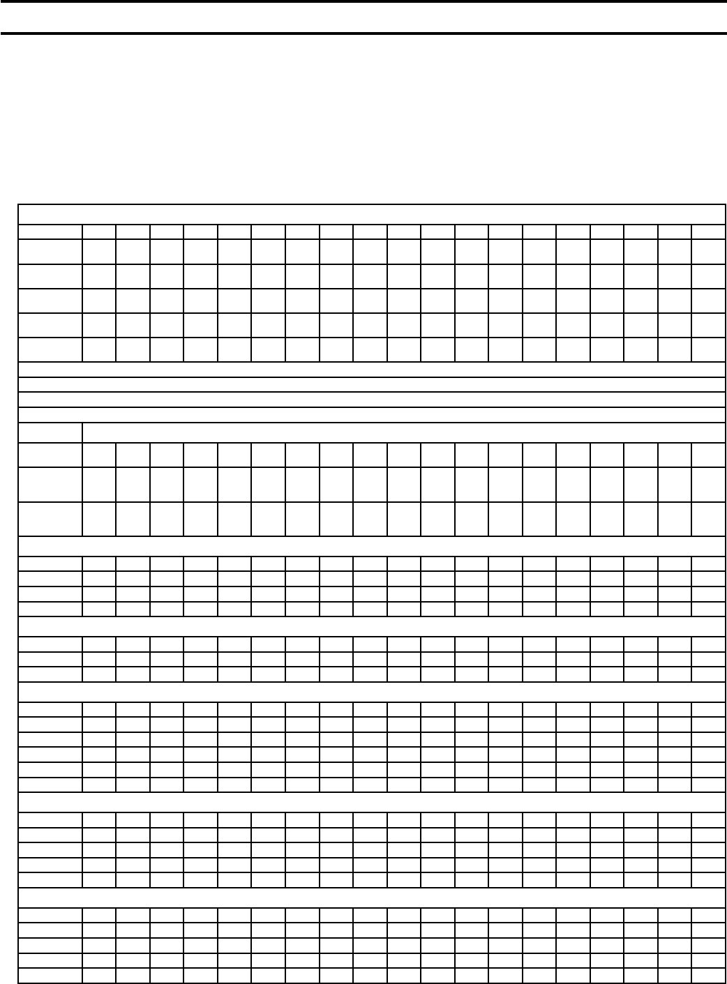
BOILER SIZE
5006B 5007B 5008B 5009B 5010B 5011B 5012B 5013B 5014B 5015B 5016B 5017B 5018B 5019B 5020B 5021B 5022B 5024B 5026B
CARTONS, PACKAGES OR BUNDLES
7 S Steam Trim Carton (Steam Boilers Only - Includes PA404 Pressure Limit Control) 4 Sizes - One Per Boiler
1 1 1 1 --- --- --- --- --- --- --- --- --- --- --- --- --- --- --- ---
2 --- --- --- 1 1 1 --- --- --- --- --- --- --- --- --- --- --- --- ---
3 --- --- --- --- --- --- 1 1 1 1 1 1 1 1 1 --- --- --- ---
4 --- --- --- --- --- --- --- --- --- --- --- --- --- --- --- 1 1 1 1
67 BC-2 Low Water Cut-off Carton (Steam Boilers Only) One Per Boiler
1111111111111111111
7 W Water Trim Carton (Water Boilers Only - Includes L4006A Temp. Limit Control) 3 Sizes - One Per Boiler
2 1 1 1 1 1 1 --- --- --- --- --- --- --- --- --- --- --- --- ---
3 --- --- --- --- --- -- 1 1 1 1 1 1 1 1 1 1 1 --- ---
4 --- --- --- --- --- --- --- --- --- --- --- --- --- --- --- --- --- 1 1
64 Low Water Cut-off Carton (Water Boilers Only) One Per Boiler
1111111111111111111
U
8 Complete Jacket Carton Assembly - One Per Boiler
9Gas Train Cartons (By Gas) 2 Sizes - One or Two Per Boiler
9
1 1* 1* 1* --- --- --- --- --- --- 2 1 --- --- --- --- --- --- --- ---
9
2 --- --- --- 1* 1 1 1 1 1 --- 1 2 2 2 2 2 2 2 2
9
3 EI 1 1 1 1 --- --- --- --- --- --- --- --- --- --- --- --- --- --- ---
EI Controls Carton(s) (By Gas) (Intermittent Elec. Ign. - 100% Shutoff - 24V.) 1 Size - One or Two Per Boiler
EI
1 1 1 1 1 --- --- --- --- --- --- --- --- --- --- --- --- --- --- ---
EI
2------------111112222222222
U
HCP
1
Plain Heater Cover Plate (Not furnished on Water Boiler Ordered With Two Tankless Heaters) One Per Boiler
1111111111111111111
U
HCP
2
Tapped (¾” NPT) Heater Cover Plate (Not Furnished on Water Boiler Ordered With Tankless Heater(s) One Per Boiler
1111111111111111111
U.S.A. EQUIPMENT CHECK LIST
INSPECT SHIPMENT carefully for any signs of damage. All equipment is carefully manufactured, inspected and packed.
Our responsibility ceases upon delivery of Boiler to carrier in good condition. Any claims for damage or shortage in
shipment must be led immediately against the carrier by the consignee. No claims for variances or shortages will be
allowed by Boiler Manufacturer, unless presented within sixty (60) days after receipt of equipment.
*Carton 91, or 92 on sizes 5006B thru 5009B is standard on all systems except EI and may be optional on 5006B thru
5009B EI.
Carton 93 is standard on sizes 5006B thru 5009B for EI systems.
This Series 5B Boiler has been approved by the Massachusetts Board of Plumbers and Gas Fitters:
Approval No. G1-0202-11A.
The Commonwealth of Massachusetts requires this product to be installed by a licensed Plumber or Gas Fitter.
SECTION I – EQUIPMENT CHECK LIST (continued)
7
BOILER SIZE
5006B 5007B 5008B 5009B 5010B 5011B 5012B 5013B 5014B 5015B 5016B 5017B 5018B 5019B 5020B 5021B 5022B 5024B 5026B
(1)
LEH 1111111111111111111
(1)
REH 1111111111111111111
(1)
C 45678891011 12 13 14 15 16 16 17 18 19 21
(2)
CX --- --- --- --- --- --- --- --- --- 1 1 1 1 1 1 2 2 3 3
(3)
CXP --- --- --- --- --- 1 1 1 1 --- --- --- --- --- 1 --- --- --- ---
(1) Section Marking Cast on Section
(2) “C” Cast on Section - When supply and return connections are tapped, section is paint stencilled “CX”
(3) “C” Cast on Section - When supply and return connections are tapped and plugged, section is paint stencilled “CXP”
CARTONS, PACKAGES, OR BUNDLES
1Base-Burner-Manifold Assembly (By Gas and By Pilot System) - One Left & One Right Req’d on 5015B and Larger Boilers
COMPLETE 1
6
1
7
1
8
1
9
1
10
1
11
1
12
1
13
1
14 --- --- --- --- --- --- --- --- --- ---
L. SUB-BASE --- --- --- --- --- --- --- --- ---
L
1S
15
L
1S
16
L
1S
17
L
1S
18
L
1S
19
L
1S
20
L
1S
21
L
1S
22
L
1S
24
L
1S
26
R. SUB-BASE --- --- --- --- --- --- --- --- ---
R
1S
8
R
1S
9
R
1S
9
R
1S
10
R
1S
10
R
1S
10
R
1S
10
R
1S
10
R
1S
13
R
1S
13
2Tie Rod Bundle(s) 4 Sizes - One to Five Per Boiler
22” --- --- 1 --- --- --- --- --- --- --- --- --- --- --- --- --- --- --- ---
27” --- --- 1 2 1 --- --- --- 2 1 --- --- --- --- 1 --- --- --- 2
37” 1 --- --- --- 1 2 1 --- 1 2 3 2 1 --- 3 4 3 1 ---
42” --- 1 --- --- --- --- 1 2 --- --- -- 1 2 3 --- --- 1 3 3
2 A Draw-up Rod Bundle(s) 3 Sizes - One to Three Per Boiler
37¾” --- --- --- --- --- 2 2 1 1 --- --- --- --- --- --- --- --- --- ---
49¼” 1 1 --- --- --- --- --- 1 1 2 2 1 1 1 --- --- --- 3 2
67¼” --- --- 1 1 1 --- --- --- --- --- --- 1 1 1 2 2 2 --- 1
3 A Boiler Assembly Carton(s) 6 Sizes - One to Five Per Boiler
3A6 1 --- --- --- --- 1 --- --- --- --- 1 --- --- --- --- 1 --- --- ---
3A7 --- 1 --- --- --- --- 1 --- --- --- --- 1 --- --- --- --- 1 --- ---
3A8 --- --- 1 --- --- --- --- 1 --- --- --- --- 1 --- --- --- --- --- 1
3A9 --- --- --- 1 --- --- --- --- 1 --- --- --- --- 1 --- --- --- 1 1
3A10 --- --- --- --- 1 --- --- --- --- 1 --- --- --- --- 1 --- --- --- ---
3AM --- --- --- --- --- 1 1 1 1 1 2 2 2 2 2 3 3 3 3
4Boiler Sealing Carton(s) 5 Sizes - One to Three Per Boiler
06 1 --- --- --- --- 2 1 --- --- --- --- --- --- --- 2 --- 1 --- ---
07 --- 1 --- --- --- --- 1 2 1 --- --- --- --- --- --- 2 --- --- ---
08 --- --- 1 --- --- --- --- --- 1 2 1 --- --- --- --- --- --- 1 2
09 --- --- --- 1 --- --- --- --- --- --- 1 2 1 --- --- --- 2 2 1
10 --- --- --- --- 1 --- --- --- --- --- --- --- 1 2 1 1 --- --- ---
5Integral Draft Hood Carton(s) 5 Sizes - One to Four Per Boiler
06 1 --- --- --- --- 2 1 --- --- --- --- --- --- --- 2 1 --- 1 ---
07 --- 1 --- --- --- --- 1 2 1 --- --- --- --- --- --- 1 2 3 3
08 --- --- 1 --- --- --- --- --- 1 2 1 --- --- --- --- --- --- --- ---
09 --- --- --- 1 --- --- --- --- --- --- 1 2 1 --- --- --- --- --- ---
10 --- --- --- --- 1 --- --- --- --- --- --- --- 1 2 1 1 1 --- ---
CANADIAN
EQUIPMENT CHECK LIST
This Equipment Check List has been provided so that the Installer can determine if all parts have been provided for the boiler
ordered. It covers standard equipment for both steam and water boilers without Tankless Heaters. Heaters or optional equipment
ordered will be in addition to, or in lieu of, equipment shown below.
By opening cartons in numerical sequence, boiler assembly is simplied. If there is an exception, it will be pointed out in the
boiler assembly procedure. When it does occur, you will nd that assembly of the boiler is further simplied.
SECTION I – EQUIPMENT CHECK LIST (continued)
8
BOILER SIZE
5006B 5007B 5008B 5009B 5010B 5011B 5012B 5013B 5014B 5015B 5016B 5017B 5018B 5019B 5020B 5021B 5022B 5024B 5026B
CARTONS, PACKAGES OR BUNDLES
7 S Steam Trim Carton (Steam Boilers Only - Includes PA404 Pressure Limit Control) 4 Sizes - One Per Boiler
1 1 1 1 --- --- --- --- --- --- --- --- --- --- --- --- --- --- --- ---
2 --- --- --- 1 1 1 --- --- --- --- --- --- --- --- --- --- --- --- ---
3 --- --- --- --- --- --- 1 1 1 1 1 1 1 1 1 --- --- --- ---
4 --- --- --- --- --- --- --- --- --- --- --- --- --- --- --- 1 1 1 1
67 BC-2 Low Water Cut-off Carton (Steam Boilers Only) One Per Boiler
1111111111111111111
7 W Water Trim Carton (Water Boilers Only - Includes L4006A Temp. Limit Control) 3 Sizes - One Per Boiler
2 1 1 1 1 1 1 --- --- --- --- --- --- --- --- --- --- --- --- ---
3 --- --- --- --- --- -- 1 1 1 1 1 1 1 1 1 1 1 1 1
4 --- --- --- --- --- --- --- --- --- --- --- --- --- --- --- --- --- 1 1
64 Low Water Cut-off Carton (Water Boilers Only) One Per Boiler
1111111111111111111
U
8 Complete Jacket Carton Assembly - One Per Boiler
c
9
1
Gas Train Cartons (By Gas) 2 Sizes - One or Two Per Boiler
c
9
1
1 1 1 --- --- --- --- --- --- 2 1 --- --- --- --- --- --- --- ---
c
9
2
--- --- --- 1 1 1 1 1 1 --- 1 2 2 2 2 2 2 2 2
THERM. Controls Carton(s) (Manual Ignition. - 100% Shutoff - 24V.) 1 Size - One or Two Per Boiler
Natural 11111111---222222222---
U
HCP
1
Plain Heater Cover Plate (Not furnished on Water Boiler Ordered With Two Tankless Heaters) One Per Boiler
1111111111111111111
U
HCP
2
Tapped (¾” NPT) Heater Cover Plate (Not Furnished on Water Boiler Ordered With Tankless Heater(s) One Per Boiler
1111111111111111111
CANADIAN
EQUIPMENT CHECK LIST
INSPECT SHIPMENT carefully for any signs of damage. All equipment is carefully manufactured, inspected and packed.
Our responsibility ceases upon delivery of Boiler to carrier in good condition. Any claims for damage or shortage in
shipment must be led immediately against the carrier by the consignee. No claims for variances or shortages will be
allowed by Boiler Manufacturer, unless presented within sixty (60) days after receipt of equipment.
SECTION I - EQUIPMENT CHECK LIST - Page 5
SECTION II - GENERAL INFORMATION - Page 10
SECTION III - INSTALLATION INSTRUCTIONS - Page 11
SECTION IV - OPERATION - Page 43
SECTION V - SERVICE - Page 64
SERVICE RECORDS - Pages 73, 110, 111
SECTION VI - REPAIR PARTS - Page 74
APPENDIX A - FIGURES - Page 105
APPENDIX B - TABLES - Page 108
SECTION I – EQUIPMENT CHECK LIST (continued)
9
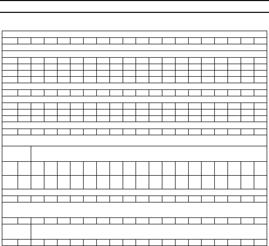
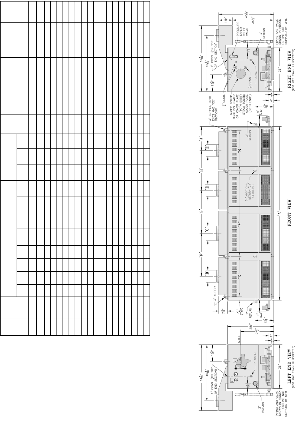
FIG. 1
DIMENSIONAL DATA
Boiler
Size
Jacket
Overall
Length
‘A’
Draft Hood Height, Size and Location
Top Supply
and Rear Return
Location
Supply
Conn.
Qty &
Size
Return Conn.
Qty. & Size
Gas Conn.
Size Nat. &
Propane
No. & Dia. of
Flue Outlets
Approx.
Shipping
Weight
(LB.)
‘B’
Dia.
‘C’
Dia.
‘D’
Dia.
‘E’
Dia. ‘F’ ‘G’ ‘H’ ‘J’ ‘K’ ‘M’ ‘N’
5006B 34 9 --- --- --- --- --- --- 17 19-3/4 --- --- (2) 3 (2) 3 1 (1) 9 1160
5007B 39-3/8 10 --- --- --- --- --- --- 19-3/4 32-1/4 --- --- (2) 3 (2) 3 1 (1) 10 1340
5008B 44-3/4 12 --- --- --- --- --- --- 22-3/8 38-3/8 --- --- (2) 3 (2) 3 1 (1) 12 1525
5009B 50-1/4 12 --- --- --- --- --- --- 25-1/8 43-3/4 --- --- (2) 3 (2) 3 1-1/4** (1) 12 1720
5010B 55-3/4 12 --- --- --- --- --- --- 27-7/8 49-1/4 --- --- (2) 3 (2) 3 1-1/4 (1) 12 1895
5011B 61-1/8 9 9 --- --- 27-1/4 --- --- 17 54-3/4 --- --- (2) 3 (2) 3 1-1/4 (2) 9 2085
5012B 66-1/2 9 10 --- --- 29-7/8 --- --- 19-3/4 60-1/8 --- --- (2) 3 (2) 3 1-1/4 (1) 9, (1) 10 2280
5013B 72 10 10 --- --- 32-5/8 --- --- 19-3/4 65-1/2 --- --- (2) 3 (2) 3 1-1/4 (2) 10 2460
5014B 77-1/2 10 12 --- --- 35-3/8 --- --- 22-3/8 71 --- --- (2) 3 (2) 3 1-1/4 (1) 10, (1) 12 2640
5015B 82-7/8 12 12 --- --- 38 --- --- 22-3/8 38-1/4 38-1/4 --- (3) 3 (2) 3, (1) 2-1/2 (2) 1* (2) 12 2870
5016B 88-1/4 12 12 --- --- 40-3/4 --- --- 25-1/8 38-1/4 43-5/8 --- (3) 3 (2) 3, (1) 2-1/2 (1) 1, (1) 1-1/4* (2) 12 3070
5017B 93-3/4 12 12 --- --- 43-1/2 --- --- 25-1/8 43-5/8 43-5/8 --- (3) 3 (2) 3, (1) 2-1/2 (2) 1-1/4* (2) 12 3265
5018B 99-1/4 12 12 --- --- 46-1/4 --- --- 27-7/8 43-5/8 49-1/8 --- (3) 3 (2) 3, (1) 2-1/2 (2) 1-1/4* (2) 12 3445
5019B 104-5/8 12 12 --- --- 49 --- --- 27-7/8 49-1/8 49-1/8 (3) 3 (2) 3, (1) 2-1/2 (2) 1-1/4* (2) 12 3620
5020B 110 9 9 12 --- 27-1/4 38 --- 27-7/8 54-1/2 49-1/8 --- (3) 3 (2) 3, (1) 2-1/2 (2) 1-1/4* (2) 9, (1) 12 3810
5021B 115-1/2 9 10 12 --- 29-7/8 40-3/4 --- 27-7/8 27-3/8 32-5/8 49-1/8 (4) 3 (2) 3, (2) 2-1/2 (2) 1-1/4* (1) 9, (1) 10, (1) 12 4005
5022B 121 10 10 12 --- 32-5/8 40-3/4 --- 27-7/8 32-3/4 32-5/8 49-1/8 (4) 3 (2) 3, (2) 2-1/2 (2) 1-1/4* (2) 10, (1) 12 4185
5024B 131-3/4 9 10 10 10 29-7/8 32-5/8 32-5/8 19-3/4 27-3/8 65-1/4 32-3/4 (5) 3 (2) 3, (3) 2-1/2 (2) 1-1/4* (1) 9, (3) 10 4530
5026B 142-3/4 10 12 10 10 35-3/8 35-3/8 32-5/8 19-3/4 32-3/4 70-3/4 32-3/4 (5) 3 (2) 3, (3) 2-1/2 (2) 1-1/4* (3) 10, (1) 12 4895
* Dual Manifolds - 5015B thru 5026B **1” - USA - EI
NOTE
1. 5006B THRU 5014B BOILERS REQUIRE
SINGLE GAS TRAIN LOCATION ON
LEFT END OF BOILER (STANDARD)
GAS TRAIN MAY BE RELOCATED
TO RIGHT END OF BOILER (EXCEPT
5012B AND 5014B BOILERS).
2. 5015B THRU 5026B BOILERS REQUIRE
DUAL GAS TRAINS.
3. GAS SUPPLY PRESSURE, IN W.C.
NATURAL GAS
MAXIMUM: 14” W.C.
MINIMUM: 5.5” W.C.
(5009B AND 5011B THRU 5014B AND
5020B THRU 5026B)
MINIMUM: 5” W.C.
(5006B THRU 5008B AND 5010B, 5015B
THRU 5019B)
LP GAS:
MAXIMUM: 14” W.C.
MINIMUM: 11” W.C.
4. WATER BOILERS - MAXIMUM DESIGN
WORKING PRESSURE: 50 PSI.
5. STEAM BOILER - MAXIMUM DESIGN
WORKING PRESSURE: 15 PSI.
6. DIMENSIONS IN INCHES
10
SECTION II – GENERAL INFORMATION
1. BOILER INSTALLATION must conform to the
requirements of the authority having jurisdiction, or in
the absence of such requirements, to:
USA – “National Fuel Gas Code, ANSI Z223.1”.
When required by the authority having jurisdiction,
the installation must conform to American Society of
Mechanical Engineers Safety Code for Controls and
Safety Devices for Automatically Fired Boilers, No.
CSD-1.
CANADA – “Installation Codes for Natural and
Propane Gas Burning Appliances and Equipment,
CAN/CSA-B149 (.1 or .2)”.
DO NOT INSTALL THIS BOILER ON CARPETING.
2. BOILER LOCATION – locate on a level NON-
COMBUSTIBLE FLOOR as close as possible to
chimney so that vent connection is short and direct.
Boiler must not be installed directly on
combustible ooring. A concrete pad is not
sufcient to protect combustible ooring.
The boiler shall be installed such that the gas ignition
system components are protected from water (dripping,
spraying, rain, etc.) during boiler operation and service
(circulator replacement, control replacement, etc.).
Do not install boiler where gasoline or other ammable
vapors or liquids, or sources of hydrocarbons (i.e.
bleachers, cleaners, chemicals, sprays, paint removers,
fabric softeners, etc. ) are used or stored.
Refer to table below for minimum clearances, service
clearances, and clearances for removal of Tankless
Heaters.
3. PROVIDE COMBUSTION AND VENTILATION
AIR.
In the USA refer to National Fuel Gas Code, NFPA
54/ANSI Z223. Section 5.3, Air for Combustion and
Ventilation. In Canada refer to Natural Gas Installation
Code, CAN/CSA-B149.1 – latest edition or Propane
Installation Code, CAN/CSA-B149.2 – latest edition.
Local code provisions may apply and should be
referenced.
Adequate combustion and ventilation air must be
provided to assure proper combustion.
a. Determine volume of space (boiler room). Rooms
communicating directly with the space, in which
the appliances are installed, through openings not
furnished with doors, are considered a part of the
space.
Volume (ft³) = Length (ft) x Width (ft) x Height (ft)
b. Determine total input of all appliances in the space.
Add inputs of all appliances in the space and round
the result to the nearest 1000 Btu per hour.
c. Determine type of space.
Divide Volume by Total Input of all appliances
in space. If the result is greater than or equal to
50 ft³/1000 Btu per hour, then it is considered an
unconned space.
If the result is less than 50 ft³/1000 Btu per hour,
then the space is considered a conned space.
d. For boiler located in an unconned space of a
conventionally constructed building, the fresh
air inltration through cracks around windows
and doors normally provides adequate air for
combustion and ventilation.
e. For boiler located in a conned space or an
unconned space in a building of unusually tight
construction, provide outdoor air with the use
of two permanent openings which communicate
directly or by duct with the outdoors or spaces
(crawl or attic) freely communicating with the
outdoors. Locate one opening within 12 inches of
top of space. Locate remaining opening within 12
inches of bottom of space. Minimum dimension
of air opening is 3 inches. Size each opening per
following:
1. Direct communication with outdoors. Minimum
free area of 1 square inch per 4,000 Btu per hour
input of all equipment in space.
2. Vertical ducts. Minimum free are of 1 square
inch per 4,000 Btu per hour input of all
CLEARANCES - From Table below and from dimensional data in Fig. 1, determine BOILER ROOM space necessary for appropriate access
to and servicing of Boiler. Consideration should be given to other appliances installed in the same area. Consult with local Building and
Safety Codes for compliance.
MINIMUM CLEARANCE - JACKET TO
COMBUSTIBLE CONSTRUCTION
RECOMMENDED
SERVICE CLEARANCE TO
NON-COMBUSTIBLE CONSTRUCTION
CLEARANCES REQ’D FOR REMOVAL
OF TANKLESS HEATER
AT-2 AT-3 AT-4
Left Side 24” (61 cm) 18” (Controls) 27” 32” 42”
Right Side 24” (61 cm) 18” (Controls) 27” 32” 42”
Front 24” (61 cm) 36” (Cleaning-Burner Removal) --- --- ---
Rear 24” (61 cm) 36” (Cleaning) --- --- ---
Top 24” (61 cm) ---------------------------------------- --- --- ---
11
SECTION III – INSTALLATION INSTRUCTIONS
equipment in space. Duct cross-sectional area
shall be same as opening free area.
3. Horizontal ducts. Minimum free area of 1
square inch per 2,000 Btu per hour input of all
equipment in space. Duct cross-sectional area
shall be same as opening free area.
Alternate method for boiler located within
conned space. Use indoor air if two permanent
openings communicate directly with additional
space(s) of sufcient volume such that combined
volume of all spaces meet criteria for unconned
space. Size each opening for minimum free area
of 1 square inch per 1,000 Btu per hour input of
all equipment in spaces, but not less than 100
square inches.
4. LOUVERS AND GRILLES of Ventilation Ducts
All outside openings should be screened and louvered.
Screens used should not be smaller than ¼ inch mesh.
Louvers will prevent the entrance of rain and snow.
a. Free area requirements need to consider the blocking
effect of louvers, grilles, or screens protecting the
openings. If the free area of the louver or grille
is not known, assume wood louvers have 20-25
percent free area and metal louvers and grilles have
60-75 percent free area.
b. Louvers and grilles must be xed in the open
position or interlocked with the equipment to open
automatically during equipment operation.
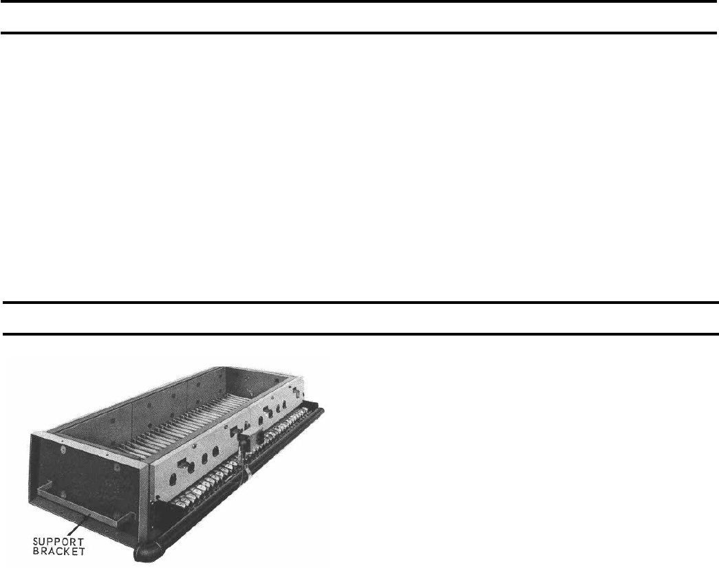
FIG. 2
SINGLE MANIFOLD BASE 5006B
THRU 5014B SECTION BOILERS
1. BASE-BURNER-MANIFOLD ASSEMBLY(S).
a. 5006B section thru 5014B section boilers require
single base assembly, see Fig. 2.
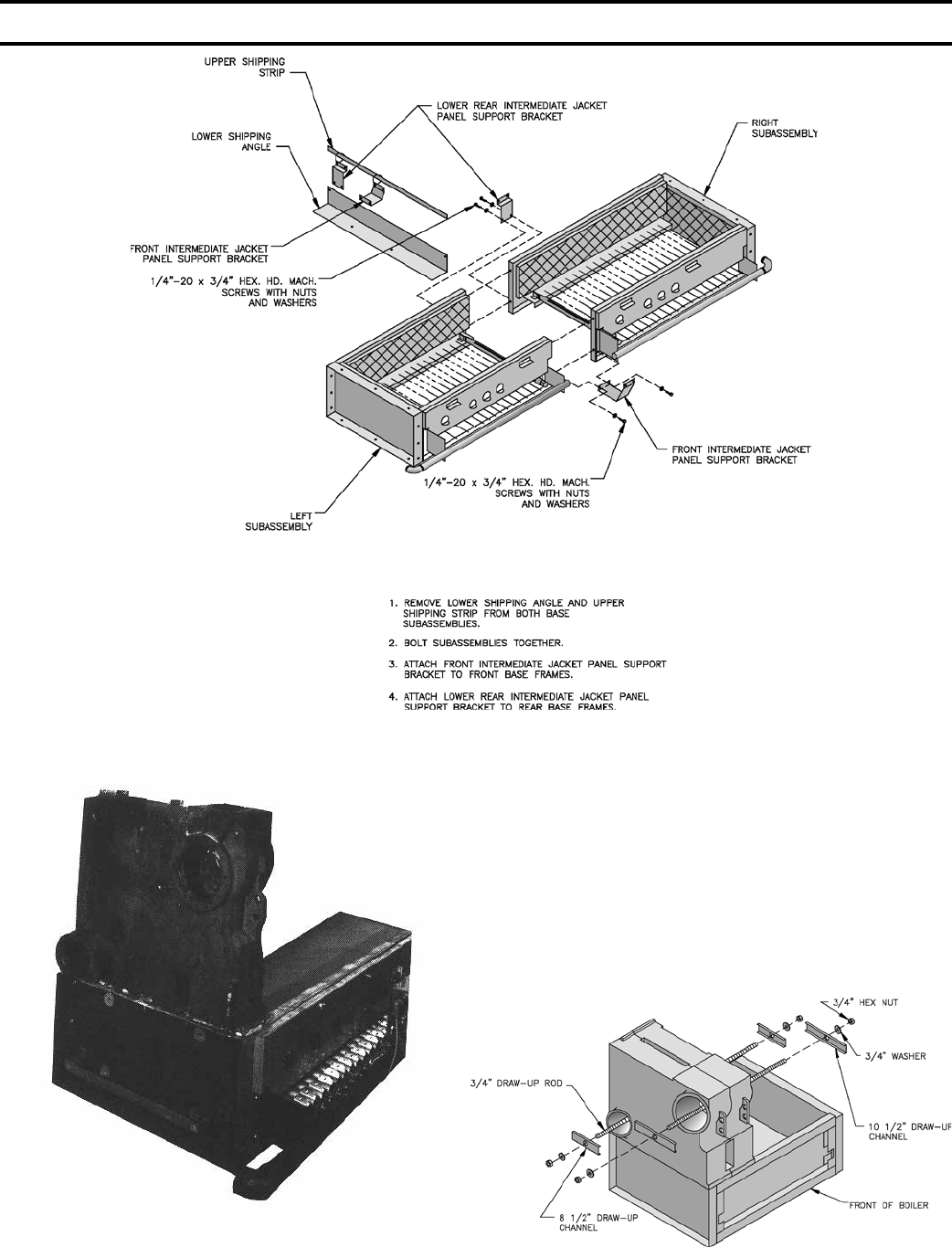
b. 5015B section thru 5026B section boilers require a
left and a right base subassembly, see Fig. 3.
Remove Base Assembly(s) From Skid(s)
c. Remove bolts securing Base Assembly(s) to
shipping skid(s) and place Base(s) in location where
Boiler is to be installed.
d. Join Base Sub-assemblies together (15 section &
larger boilers) by rst removing upper shipping
strip and lower shipping angles from subassemblies.
Use (4) ¼”-20 x ¾” MS, nuts and washers to attach
subassemblies, see Fig. 3.
e. Attach Front Intermediate Jacket Panel Support
Bracket and Lower Rear Intermediate Panel Support
Bracket to lower channel on Front Base Frame and
Rear Base Frame, respectively, using (4) ¼”-20 x
¾” MS, nuts and washers.
f. Base must be level in both directions and secure on
the oor. Shim and grout under Base if necessary.
g. Place cardboard covering over the top of the burner
assembly to protect them during the assembly of the
boiler sections.
2. CLEAN BOILER SECTIONS inside and out to remove
dirt due to shipment and handling.
Open Tie Rod Bundle(s). Open Draw-up Rod
Bundle(s).
Open Boiler Assembly Carton(s).
3. SET LEFT END SECTION ON BASE so that locating
lugs on bottom of section go inside Front and Rear Base
Frames. Slide section on base until these lugs strike
High Base End Panel at left end of Base, see Fig. 4.
(Note – if High Base End Panel is at right end of Base,
section assembly must start with Right End Section).
Left end sections are identied by “LEH” cast on
section; Right End Sections are identied by “REH”
cast on section.
4. CLEAN NIPPLES AND NIPPLE PORTS thoroughly
with a de-greasing solvent. Use the Loctite® #592
supplied to lubricate the nipples and nipple ports.
Apply the lubricant to the nipples and nipple ports, then
use a brush to disperse it evenly around the nipples and
the nipple ports. Use approximately 25 ml of Loctite®
#592 per ueway [(1) 7” and (2) 3” nipples and their
(6) corresponding nipple ports]. Use Nipple Gauge
furnished – follow instructions included with gauge to
set nipples. USE ALL PRECAUTIONS TO AVOID
COCKED NIPPLES.
5. PAINT ALL GROUND SURFACES of each section
with the Sealer Compound furnished.
6. ASSEMBLE CENTER SECTIONS. Refer to Fig. 6
for proper location of Tapped, and sometimes plugged,
SECTION II – GENERAL INFORMATION (continued)
12
Center Sections on 11 section and larger boilers. THIS
IS IMPORTANT.
a. Carefully join a Center Section with nipples in
adjoining section and bump lightly to secure.
b. Run nut approximately 8” on two (2) ¾” draw-up
rods of equal length. (Note – more than one set of
draw-up rods are furnished on 8 section and larger
boilers). Place draw-up channel and one at washer
against nut.
FIG. 3
DUAL MANIFOLD BASES - 5015B THRU 5026B SECTION BOILERS
FIG. 4
LEH SECTION ON BASE FIG. 5
ASSEMBLY OF CENTER SECTIONS
SECTION III – INSTALLATION INSTRUCTIONS (continued)
13
FIG. 6
ARRANGEMENT OF SECTIONS AND CANOPY(S)
SECTION III – INSTALLATION INSTRUCTIONS (continued)
14
c. Insert short end of draw-up rod through front & rear
nipple ports on both sections, see Fig. 5.
d. Place two (2) at washers, draw-up channel and a
nut on each end of draw-up rods and nger tighten.
e. DRAW UP CENTER SECTION SLOWLY AND
EVENLY, tightening each DRAW-UP ROD a little
at a time so that sections are equally spaced. KEEP
NIPPLES ALIGNED WITH NIPPLE PORTS. If
necessary, tap Nipples lightly with a blunt tool or
rod to keep Nipples from cocking while Sections are
being drawn up. DO NOT DRAW UP SECTION(S)
WHEN NIPPLES ARE COCKED. Continue
tightening Draw-Up Rods equally until Sections
meet iron-to-iron on the ground surface. BUMPING
OUTER EDGES OF SECTION WITH WOODEN
BLOCK WILL EASE DRAW-UP OPERATION.
f. KEEP DRAW-UP ROD THREADS, NUTS AND
WASHERS LUBRICATED with grease or heavy oil
to prevent damage to rods and threads and to make
assembling easier.
g. USING A PINCH BAR, insert WOOD WEDGES
under last Center Section assembled so as to raise
it just above Boiler Base. This will keep the next
section to be assembled above the base, thus making
it easier to join and draw-up. MOVE WOOD
WEDGES FORWARD EACH time a Section has
been drawn up.
7. ASSEMBLE REMAINING END SECTION WITH
DRAW-UP RODS in a manner similar to that for
assembling Center Sections. Remove wedges from
under Boiler. Be sure Boiler is aligned and seated on
Base.
a. After section assembly is completed install 5/8” tie
rods from tie rod bundle through the upper lug holes
in the front of Boiler and Lower lug holes in the rear
of Boiler sections and tighten until they are nger
tight only, to allow for expansion. This is necessary
in order to allow clearance for installation of Flue
cover plates. Finally, remove ¾” draw-up rods from
nipple ports.
FIG. 7
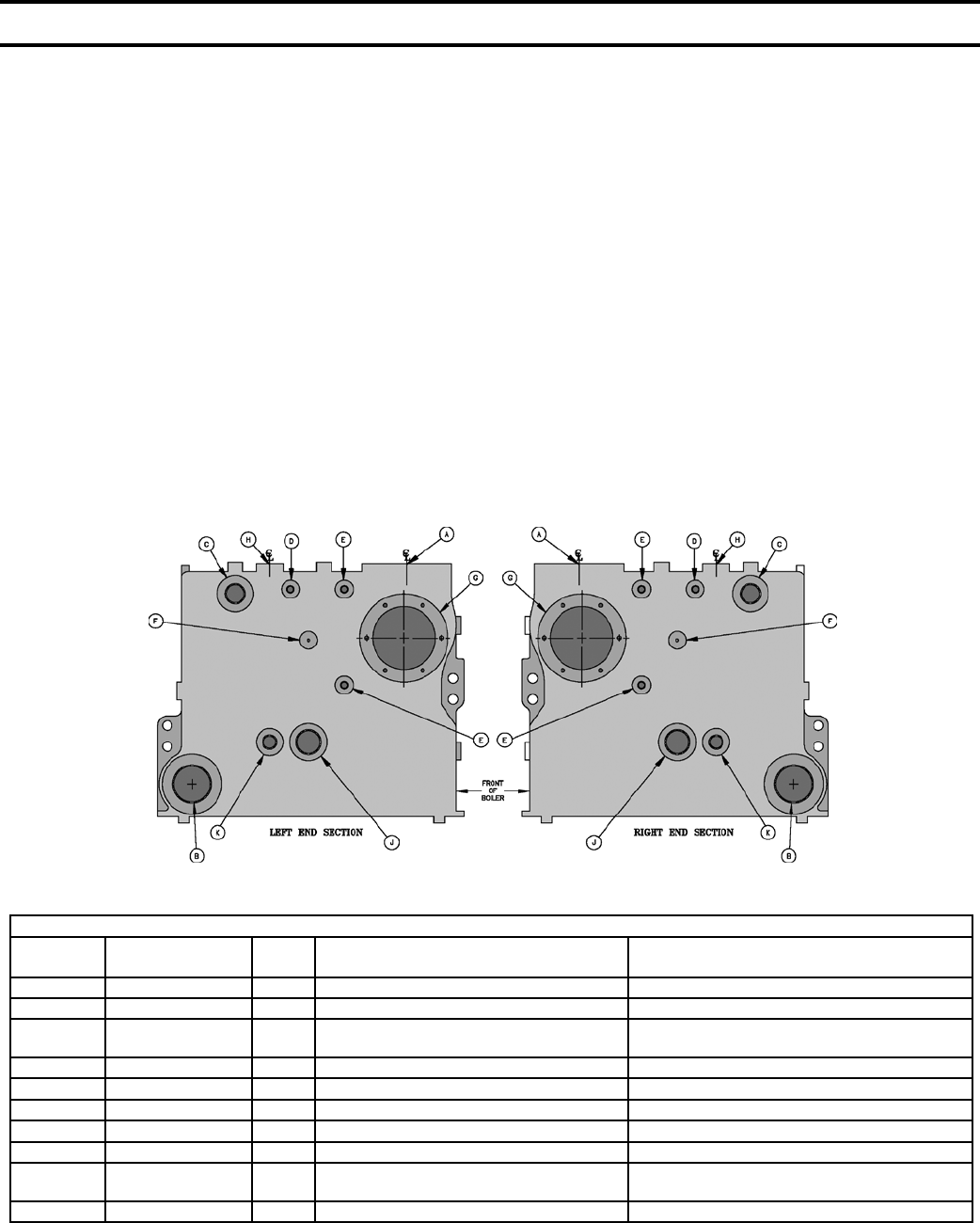
PURPOSE OF TAPPINGS AND THEIR LOCATIONS
PURPOSE OF TAPPINGS 1
Location Tapping Per
End Section Size Steam Boilers Water Boilers
A 1 3” Supply Supply
B 1 3” Return Return
C21 1-1/2” Pressure Operating Control
(Bushed to 1/4”)
Temperature Operating Control (less heater)
Bushed to 3/4”; Plug (with heater)
D 1 1/2” Pressure Gauge Theraltimeter
E 2 1/2” Water Gauge, LWCO & Pressure Limit Plug
F 1 3/8” Try-Cock (Special Order) ----
G31 ---- Cover Plate Cover Plate or Tankless Heater
H 1 1” See Note 4 See Note 4
J 1 1-1/2” Indirect Water Heater
Supply or Return ----
K 1 3/4” Indirect Water Heater Limit ----
1 Tappings on both end sections are identical - Recommend trim be installed in left end section or on same end as gas train.
2 This tapping is used for safety valve and surface blowoff (steam boilers) and safety relief valve (water boilers) on end not equipped with trim.
3 Temperature operating control location on tankless heater equipped boilers. Also alternate operating control location, tapped cover plate.
4 If using a oat type LWCO, feeder or pump controller on a steam boiler that does not use quick connect hook up ttings, install between
tappings H and return B. Use opposite return B for system return connection. Water boilers using a probe LWCO must mount probe in
supply pipe above boiler without any stop valves.
SECTION III – INSTALLATION INSTRUCTIONS (continued)
15
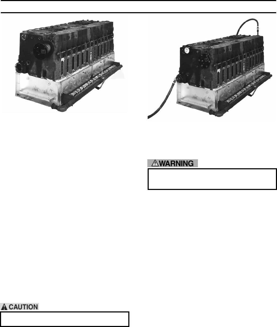
FIG. 8
INSTALLATION OF BUILT-IN HEATER FIG. 9
TESTING BOILER ASSEMBLY FOR LEAKS
Open Steam or Water Trim Carton
8. USE THE PLUGS IN THIS CARTON to plug tappings
in End Sections that will not be utilized on nal
installation, see Fig. 7.
Open Tankless Heater Carton(s) If Supplied.
Open Heater Opening Cover Plate Carton(s).
9. INSTALL BUILT-IN WATER HEATER(S) OR
HEATER OPENING COVER PLATE(S), See Fig.
8. Heater may be installed in either End Section or,
in some cases, in both End Sections. Heater Opening
Cover Plates are used to cover any unused heater
openings.
a. Place rubber gasket against surface of plate and
align holes.
b. Place washer on each of 3/8” Cap Screws furnished
and insert cap screws through plate and gasket.
Start all screws in taps before nal tightening.
10. HYDROSTATIC TEST, see Fig. 9: After the boiler
sections have been assembled, it is essential that the
boiler be hydrostatically tested before the canopy, ue
cover plates, jacket, or piping is installed.
a. Plug all boiler tappings and ll boiler completely
with cold water.
DO NOT install gauge until after hydrostatic
testing the boiler. Gauge failure may result.
b. All completed boilers must satisfactorily pass the
prescribed hydrostatic test.
(1) STEAM BOILERS: The assembled boiler must
be subjected to a hydrostatic test of 45 psig to 55
psig.
(2) HOT WATER BOILERS: The assembled boiler
must be subjected to a hydrostatic test of 75 psig
to 85 psig.
Failure to properly hydrotest all boilers at the
correct pressure may result in section assembly
failure in operation.
11. EXAMINE BOILER CAREFULLY, INSIDE AND
OUTSIDE, to insure against leaks from cocked nipples
or through concealed breakage caused in shipping and
handling. This precaution is for your protection and
will simplify handling of necessary replacements and
adjustment claims. After making certain that there are
no leaks, drain boiler and remove plugs for boiler trim
and other connections.
Open Boiler Sealing Carton.
12. SEAL BETWEEN BOILER SECTIONS AND BASE,
see Fig. 10.
a. Push ¾” braided ceramic bre Rope (furnished) into
gap between bottom of End Section and Low Base
End Panel until rope touches Front and Rear Base
Frames. Place the 1-1/2” x 2” x 5/8” steel spacers
between low base panel and section and in front of
rope – align holes. Secure section to low base end
panel with 3/8”-16 x 2” Cap Screws, washers and
nuts.
b. Secure opposite end section to high base end panel
with 3/8”-16 x 2” Cap Screws, washers and nuts.
c. Apply Furnace Cement to gaps between section
assembly and base to make gas tight seal.
d. Check all joints between Boiler sections and use
remaining Furnace Cement or Sealer Compound to
make joints gas tight.
SECTION III – INSTALLATION INSTRUCTIONS (continued)
16
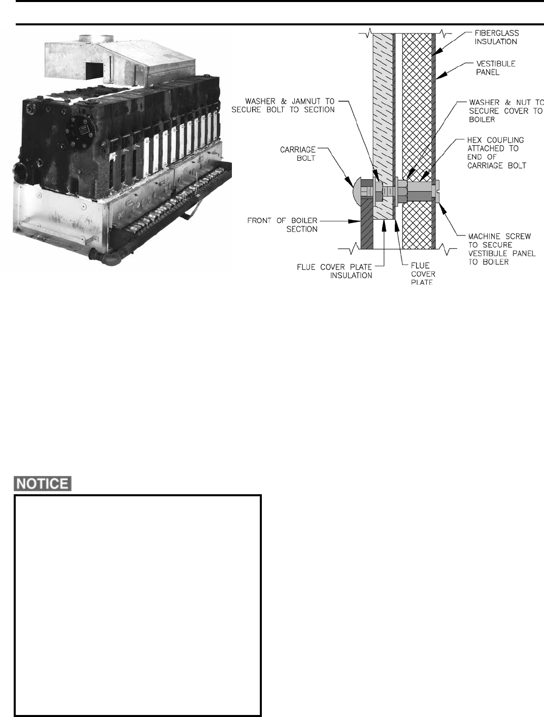
13. INSTALL FLUE COVER PLATES over cleanout
openings on Front and Rear of Boiler. Use ¼” Carriage
Bolts installed at top and bottom of ue openings and
secure with washer and jam nut to provide a xed
stud. Install ue cover plates over studs with insulation
against Boiler and secure with washers and nuts, see
Fig. 11.
14. CONNECT SUPPLY AND RETURN PIPING TO
HEATING SYSTEM.
CLEARANCES – Steam and Hot water pipes shall
have clearances of at least ½” from all combustible
construction.
Before using copper for steam piping, consider
the following characteristics of copper piping:
1) high coefcient of thermal expansion can
induce mechanical stresses and cause expansion/
contraction noises if not accounted for in the
piping system design and installation,
2) high heat transfer rate (heat loss) of uninsulated
copper piping must be included in the normal
piping and pickup factors used to size the boiler,
3) soldering or brazing pastes and uxes that end
up in the system can cause poor heat transfer,
surging, and unsteady water line and wet steam
if not thoroughly removed during the boil out
procedure and,
4) galvanic corrosion of the adjoining metal may
occur due to dissimilar metals in certain water
chemistries if dielectric unions are not used.
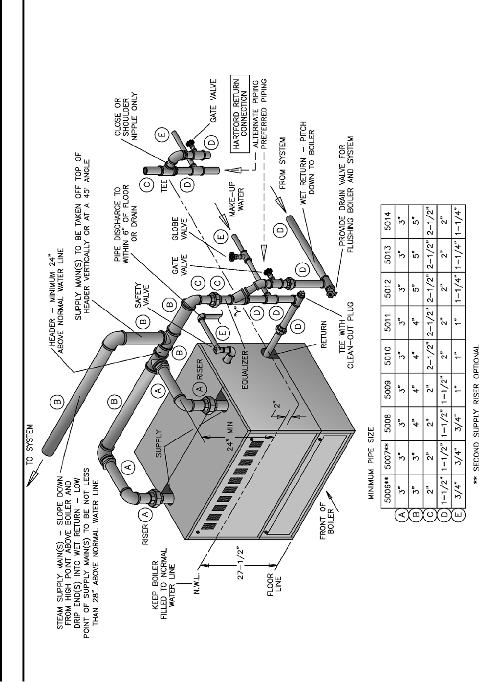
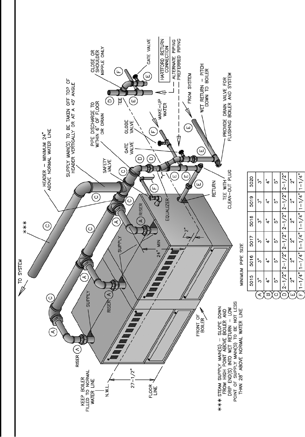
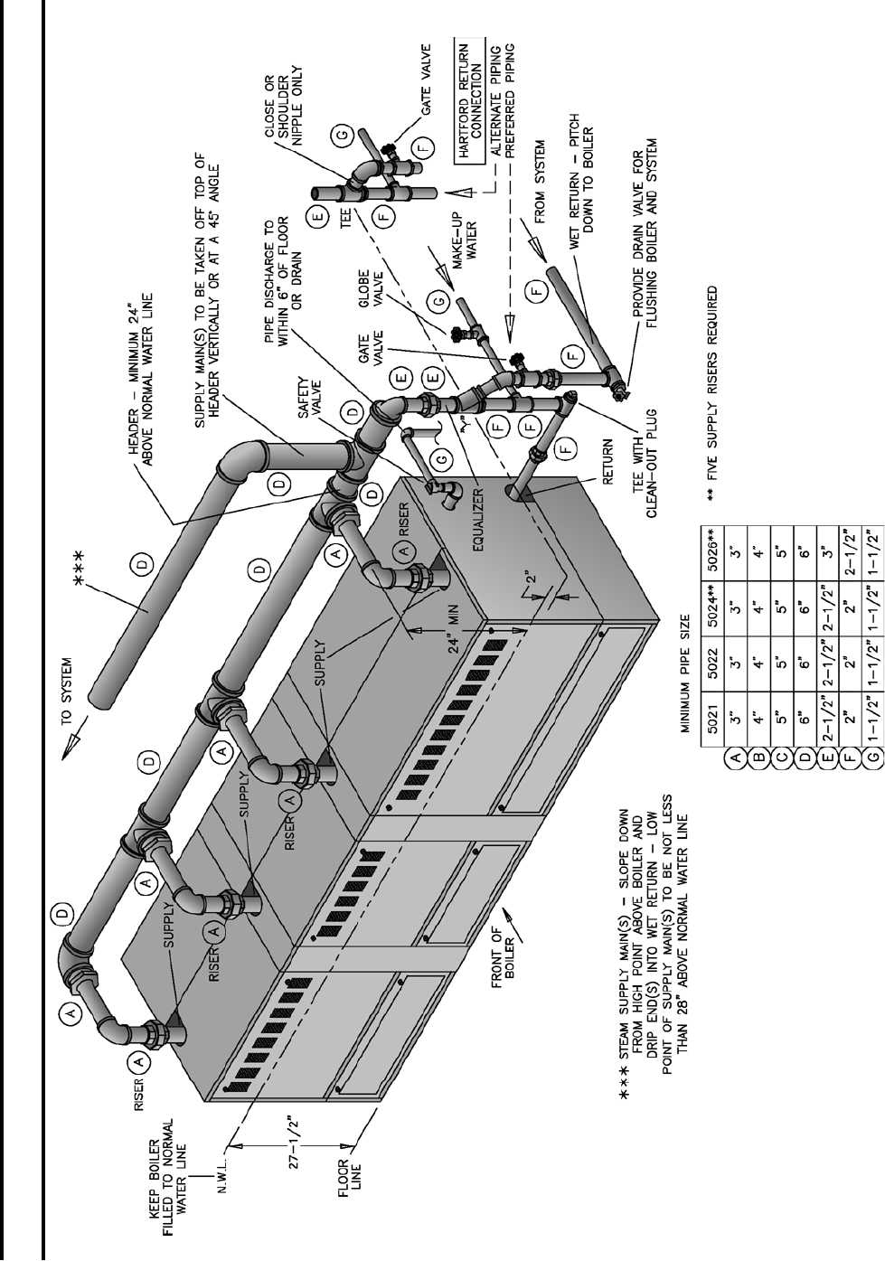
a. With Steam Heating System, refer to Fig. 12, 13, 14
or 15.
b. With Forced Circulation HOT WATER HEATING
SYSTEMS, see Fig. 16A and 16B. For additional
reference, consult I=B=R Installation and Piping
Guide No. 250.
NOTE: When Hot Water Heating Boilers are
connected to Heating Coils located in Air Handling
Units where they may be exposed to refrigerated
air circulation, the Boiler Piping System must
be equipped with Flow Control Valves or other
automatic means to prevent gravity circulation of
the Boiler Water during the cooling cycle.
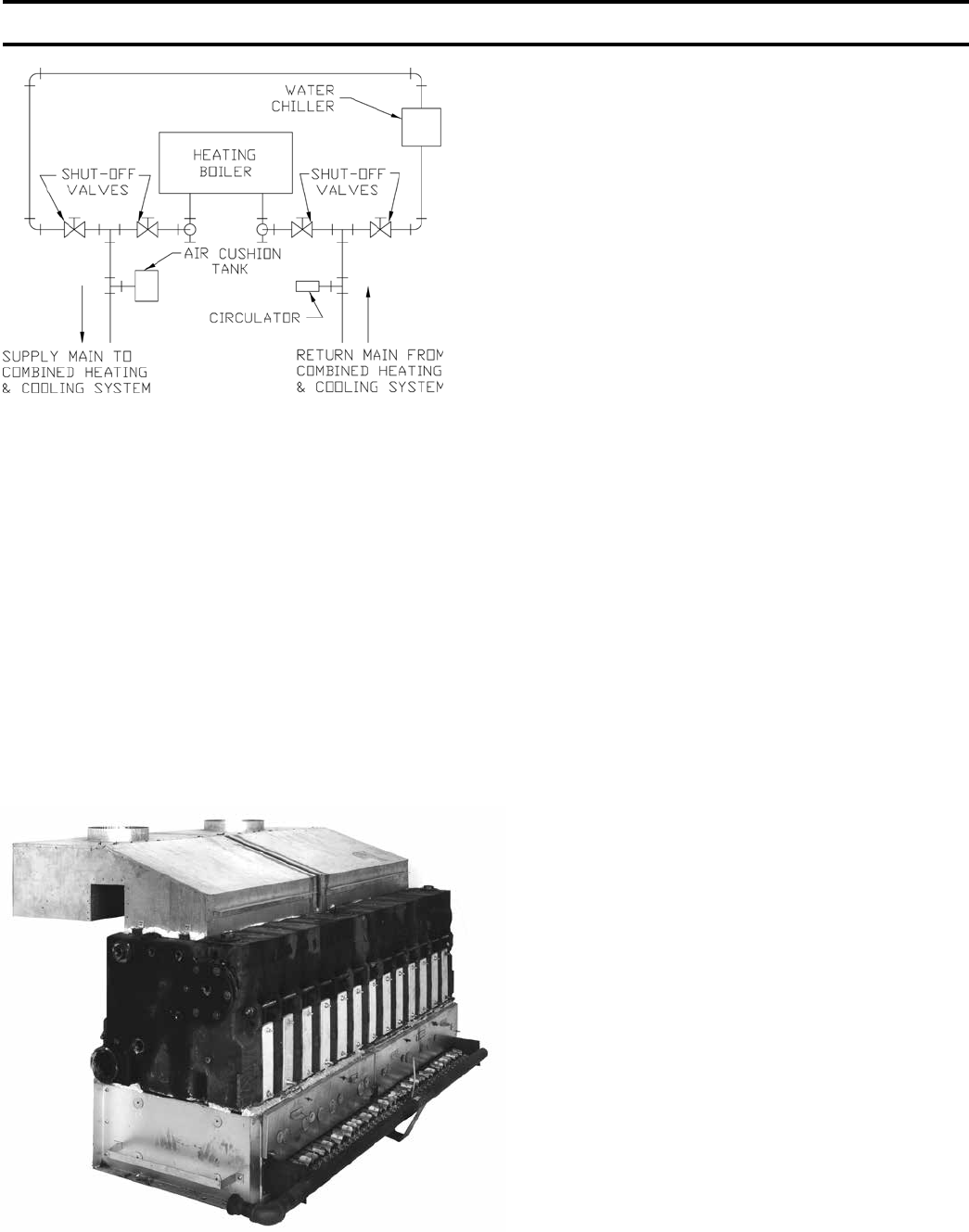
c. With COMBINATION HEATING AND COOLING
(REFRIGERATION) SYSTEMS having the same
Distributing Units, Piping and Circulator, See Fig.
17. For additional reference, consult ASHRAE
Systems Handbook 2008 Edition.
d. NOTE: Valves must be installed in the supply and
return branches to the Heating Boiler and Water
Chiller so as to prevent circulation of Chilled Water
through the Boiler or Heated Water through the
Chiller.
OXYGEN CORROSION:
Oxygen contamination of the boiler water will cause
corrosion of the iron and steel boiler components,
which can lead to failure. As such, any system must
be designed to prevent oxygen absorption in the rst
place or prevent it from reaching the boiler. Problems
caused by oxygen contamination of boiler water are not
covered by Burnham’s standard warranty.
FIG. 10
SEALING OF BASE, INSTALLATION OF
FLUE COVERS AND CANOPIES
FIG. 11
ATTACHMENT OF FLUE COVERS
SECTION III – INSTALLATION INSTRUCTIONS (continued)
17
FIG. 12
RECOMMENDED STEAM BOILER PIPING, GRAVITY RETURN
I OR 2 SUPPLY CONNECTIONS - 5006B THRU 5014B
SECTION III – INSTALLATION INSTRUCTIONS (continued)
18
FIG. 13
RECOMMENDED STEAM BOILER PIPING, GRAVITY RETURN
3 SUPPLY CONNECTIONS - 5015B THRU 5020B
SECTION III – INSTALLATION INSTRUCTIONS (continued)
19
FIG. 14
RECOMMENDED STEAM BOILER PIPING, GRAVITY RETURN
4 OR 5 SUPPLY CONNECTIONS - 5021B THRU 5026B
SECTION III – INSTALLATION INSTRUCTIONS (continued)
20
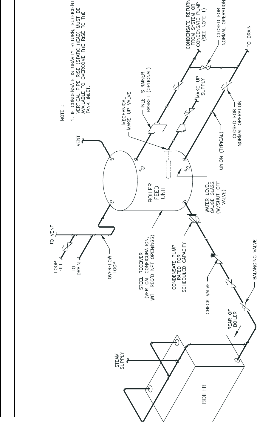
FIG. 15
TYPICAL STEAM PIPING ARRANGEMENT FOR BOILERS WITH PUMPED CONDENSATE RETURN AND BOILER FEED UNIT
SECTION III – INSTALLATION INSTRUCTIONS (continued)
21
FIG. 16A
RECOMMENDED WATER BOILER PIPING
1 SUPPLY CONNECTION & 1 RETURN CONNECTION
SIZES 5006B THRU 5019B
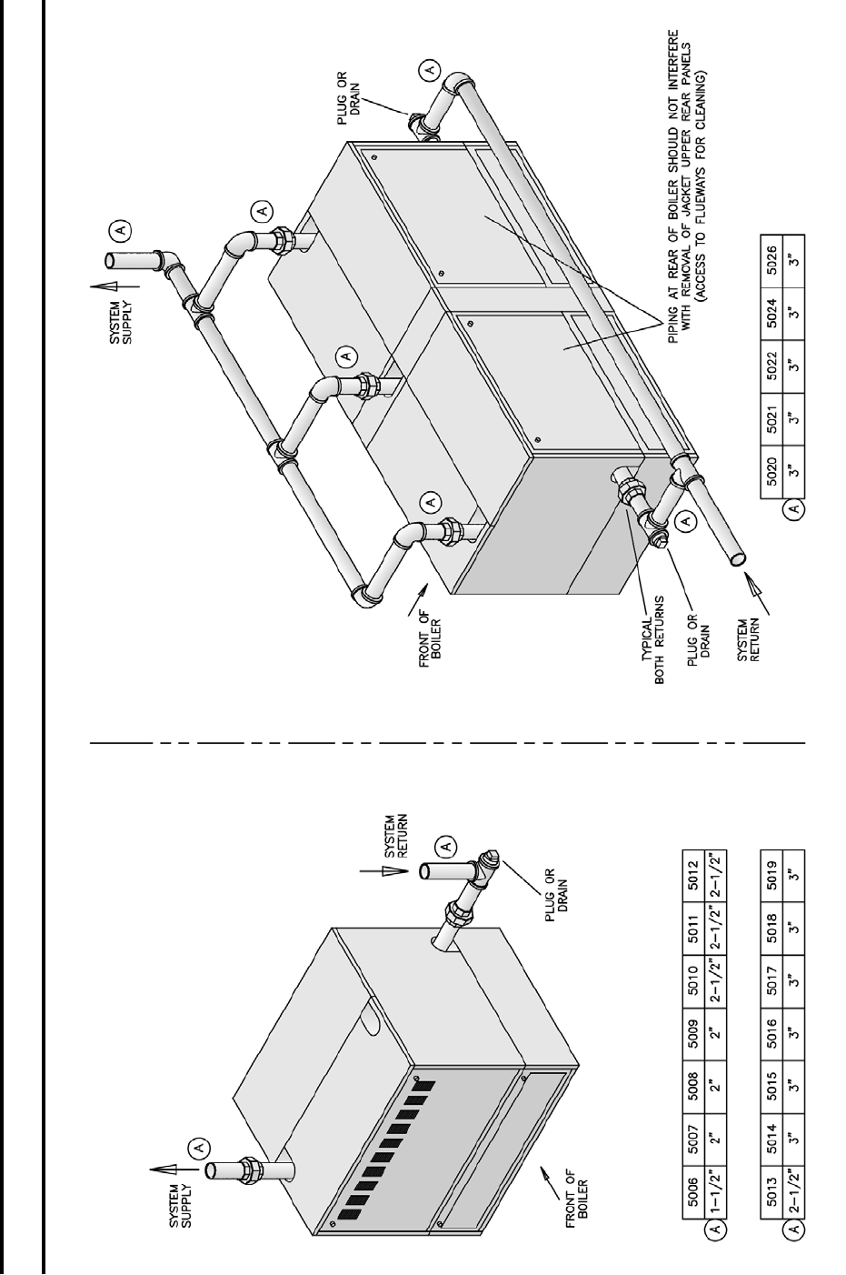
FIG. 16B
RECOMMENDED WATER BOILER PIPING
3 SUPPLY CONNECTIONS & 2 RETURN CONNECTIONS
SIZES 5020B THRU 5026B
SECTION III – INSTALLATION INSTRUCTIONS (continued)
22
There are many possible causes of oxygen
contamination such as:
1. Addition of excessive make-up water as a result of
system leaks.
2. Absorption through open tanks and ttings.
3. Oxygen permeable materials in the distribution
system.
In order to insure long product life, oxygen sources
should be eliminated. This can be accomplished by
taking the following measures:
FIG. 17
RECOMMENDED BOILER PIPING FOR
COMBINATION HEATING & COOLING SYSTEMS
1. Repairing system leaks to eliminate the need for
addition of make-up water.
2. Eliminating open tanks from the system.
3. Eliminating and/or repairing ttings which allow
oxygen absorption.
4. Use of non-permeable materials in the distribution
system.
5. Isolating the boiler from the system water by
installing a heat exchanger.
Open Jacket Parts Carton
15. INSTALLATION OF JACKET PARTS COMMON TO
ALL BOILER SIZES
1. Attach Lower Jacket End Panel Support Bracket to
Base End Panel (Both ends) using ¼”-20 x ½” self-
tapping screws, see Fig. 2 and 18.
2. Attach Lower Left and Lower Right Jacket End
Panels to their respective brackets using #10-32 x
½” self-tapping screws, see Fig. 19.
3. See Fig. 7 “Purpose of Tappings and Their
Location” and remove necessary knockouts from
Upper Left and from Upper Right Jacket End
Panels.
4. Place Upper Right End Panel on top of Lower
Right End Panel with lip on bottom of Upper Panel
positioned behind Lower Panel. Secure to section
using #10-32 x ½” self-tapping screws. Attach
Upper Left End Panel in a similar manner, see Fig.
19.
NOTE: FOR INSTALLATION OF THE
FRAMEWORK FOR THE LOWER UNCOMMON
JACKET PARTS REFER TO THE FOLLOWING:
a. 5006B thru 5010B section boilers – Paragraph
16, Fig. 21
b. 5011B thru 5026B section boilers – Paragraph
30, Fig. 24, 25 or 26
COMPLETION OF JACKET INSTALLATION –
5006B THRU 5010B SECTION BOILERS
NOTE: Do not tighten any screws until Jacket
installation is complete.
INSTALLATION OF LOWER FRAMEWORK
16. With “U” channel facing down, slip upper front channel
behind joints formed by End Panels and secure to End
Panels using #8 SMS. Position Lower Front Channel
so that “U” of channel faces boiler. Slip Lower Front
Channel behind Lower End Panels and secure with
#8 SMS. Repeat similar procedure for installation of
Upper Rear and Lower Rear Channels.
17. INSTALLATION OF VESTIBULE PANEL refer to
Fig. 20.
FIG. 18
INSTALLATION OF JACKET SUPPORT
BRACKETS TO BASE END PANELS
SECTION III – INSTALLATION INSTRUCTIONS (continued)

23
FIG. 19
INSTALLATION OF JACKET END PANELS
FIG. 20
VESTIBULE ATTACHMENT DIAGRAM
Attach Hex Couplings to end of
Carriage Bolts which secure ue
cover plates.
NOTE: Select Carriage Bolts which
line up with holes in the Vestibule
Panel.
18. SECURE VESTIBULE PANEL TO
HEX COUPLINGS using ¼”-20 x
3/8” slotted pan head machine screws.
19. ATTACH REAR TOP JACKET
PANEL TO UPPER END PANELS
using #8 SMS. Refer to Fig. 21.
20. INSTALLATION OF CANOPY-
DRAFT HOOD 5006B thru 5010B
Section Boilers, see Fig. 22. Place
Cerafelt strips on top of section
assembly next to ledges formed by
center sections and next to ledge on
end sections. Overlap at corners.
21. SECURE CANOPY-DRAFT HOOD
with 5/16”-18 x 5/8” MS driven into
the tapped lugs provided for this
purpose on top of the sections. Two
screws are required at each end.
Refer to Fig. 23.
SECTION III – INSTALLATION INSTRUCTIONS (continued)
24
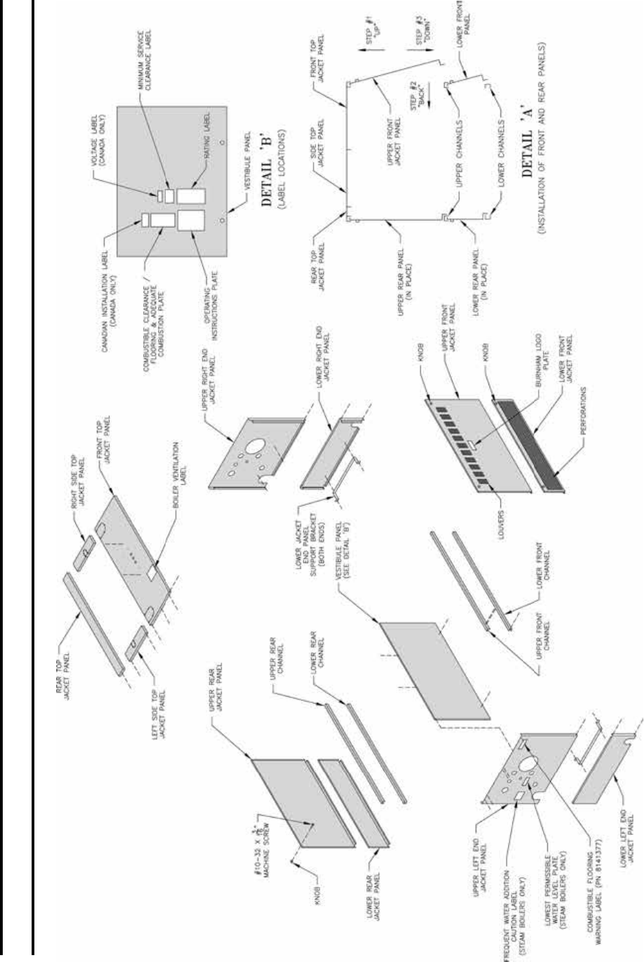
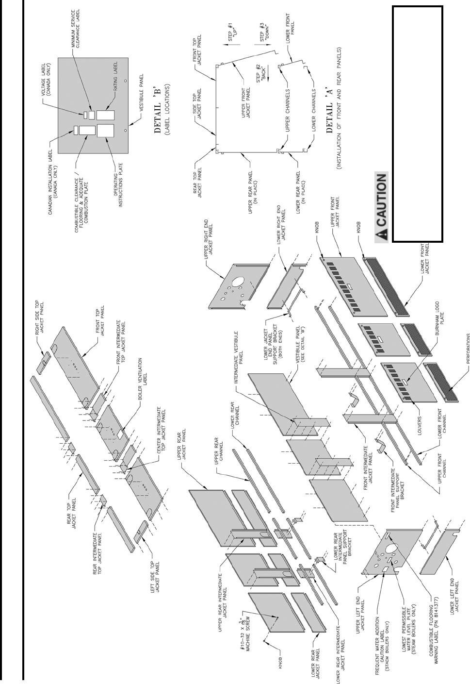
FIG. 21
EXPLODED VIEW OF JACKET
5006B THRU 5010B SECTION BOILERS
SECTION III – INSTALLATION INSTRUCTIONS (continued)
25
FIG. 22
SECURING OF CANOPY/DRAFT HOOD
SECTION III – INSTALLATION INSTRUCTIONS (continued)
26
FIG. 23
CANOPY/DRAFT HOOD MOUNTING DIAGRAM
SECTION III – INSTALLATION INSTRUCTIONS (continued)
27
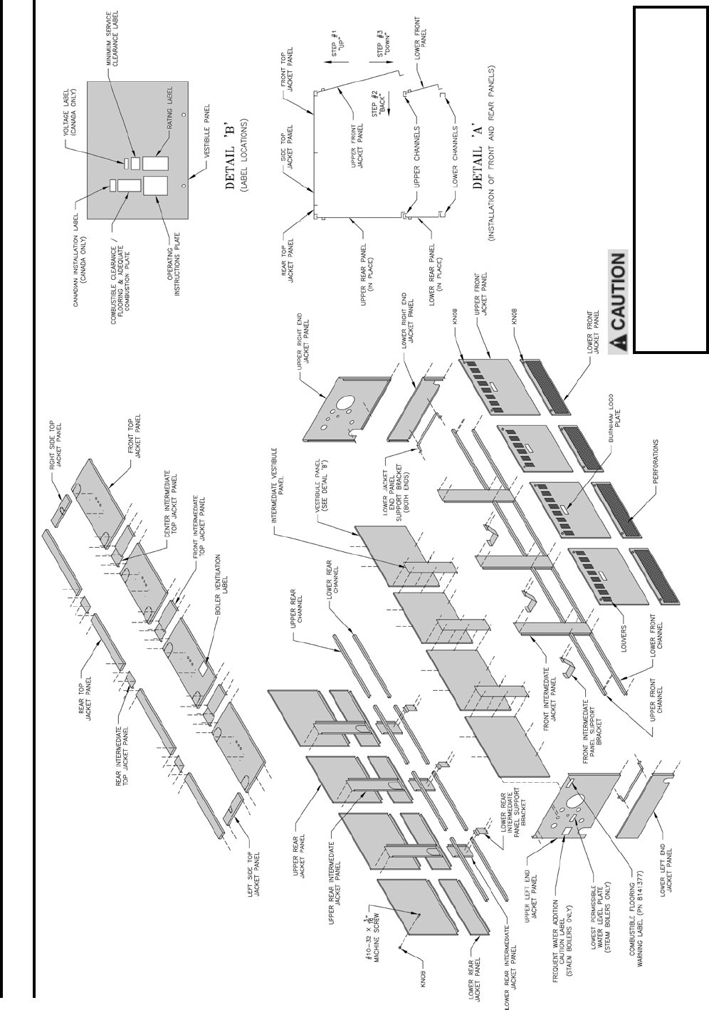
FIG. 24
EXPLODED VIEW OF JACKET
5011B THRU 5019B SECTION BOILERS
SECTION III – INSTALLATION INSTRUCTIONS (continued)
28
22. INSTALLATION OF TOP FRONT JACKET PANEL
a. Remove knockout for supply piping (right or left for
water boilers – both knockouts for steam boilers)
refer to recommended boiler piping diagrams in this
manual.
b. Attach Top Front Jacket Panel to left and right end
Jacket Panel and to Top Flange on the Vestibule
Panel using #8 SMS. See Fig. 24.
23. INSTALLATION OF LEFT AND RIGHT TOP SIDE
JACKET PANEL
a. Remove knockout, right or left, only if needed.
(See Fig. 7 for purpose of tappings), secure top side
panels to upper end panels with #8 SMS.
24. INSTALL KNOBS on the four remaining panels using
#10-32 x 3/16” MS.
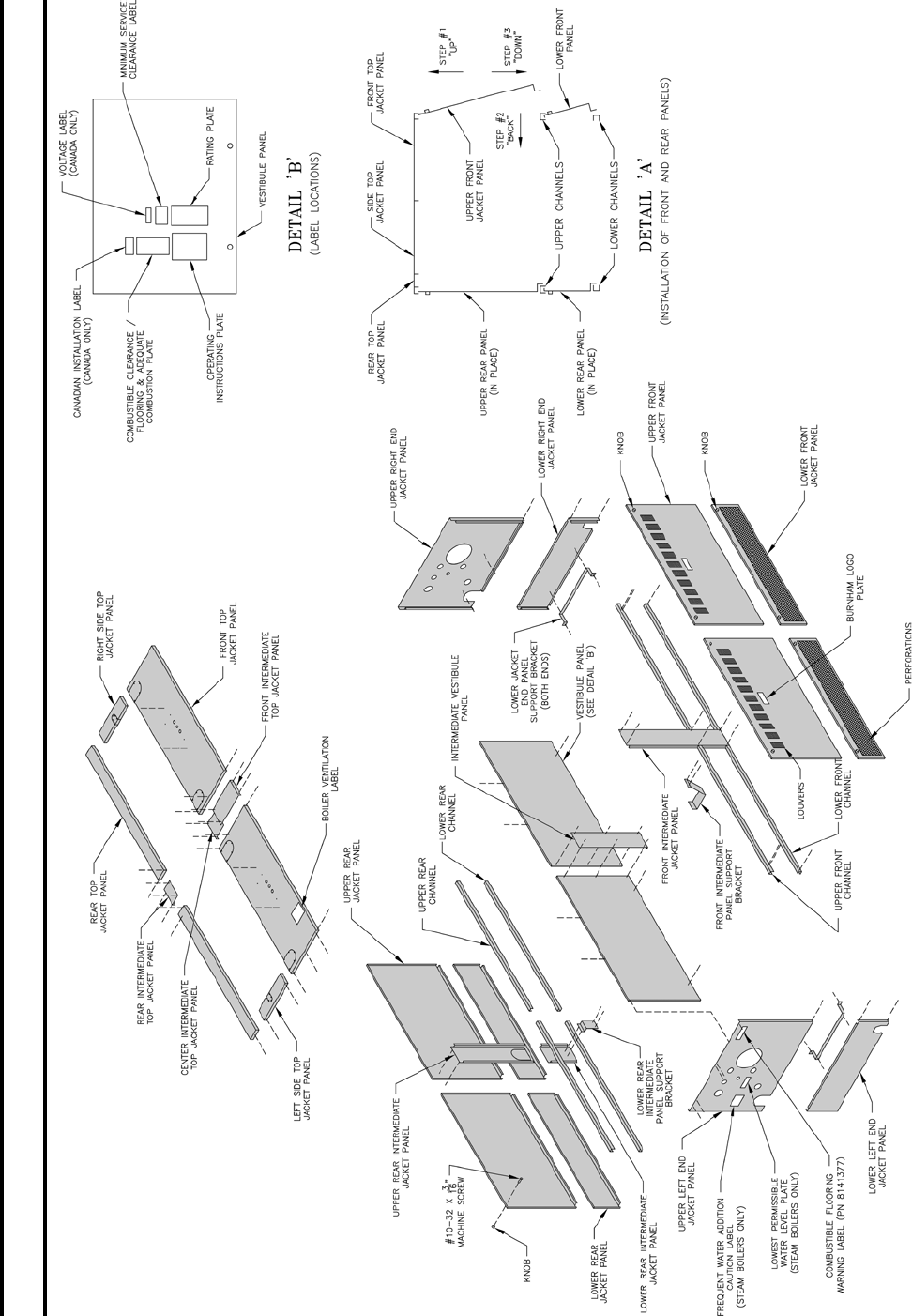
25. INSTALL UPPER FRONT, LOWER FRONT, UPPER
REAR AND LOWER REAR PANELS using procedure
described in detail “A” of Fig. 25.
Panel with louvers must be at front of boiler for
ventilation of vestibule. Panel with perforations
must be at front of boiler for ventilation and
combustion air.
26. TIGHTEN ALL SHEET METAL SCREWS.
27. INSTALL THE FOLLOWING PLATES OR LABELS
which are found in the Instruction Envelope. See Fig.
21 or 24 for location.
(1) Rating Label
(2) Operating Instruction Plate (#8 SMS required to
fasten)
(3) Combustible Clearance Flooring & Adequate
Combustion Plate
(4) Minimum Service Clearance Label (self-adhesive)
(5) Burnham Logo (self-adhesive) – Apply to Top
Panel
(6) Boiler Ventilation For Your Safety Label – Apply
to Top Panel
(7) Proceed to Paragraph 33 (Steam Boilers) or
Paragraph 34 (Water Boilers).
COMPLETION OF JACKET INSTALLATION 5011B
THRU 5026B SECTION BOILERS.
28. PARAGRAPHS 1 THRU 4 HAVE ALREADY BEEN
COMPLETED. Refer to Paragraph 16 for installation
of lower framework.
a. Install Vestibule Panel(s) – refer to Fig. 21 and 24.
Attach Hex Couplings to end of Carriage Bolts
which secure Flue Cover Plates.
NOTE: Select Carriage Bolts which line up with holes
in the Vestibule Panel(s).
b. Attach Intermediate Vestibule Panel(s) to one of the
Vestibule Panel(s) using #8 SMS.
c. Secure Left and Right Vestibule Panels to Hex
Couplings using ¼”-20 x 3/8” slotted pan head
machine screws.
d. Attach the Lower Rear Intermediate Panels to the
Lower Rear Intermediate Panel Support Bracket(s)
using #10-32 x ½” self tapping screws.
e. Attach the Upper Rear Intermediate Panel(s) to the
Lower Rear Intermediate Panel(s) using #8 SMS.
f. Attach Rear Top Intermediate Jacket Panel(s) to Rear
Top Left and Right Jacket Panels using #8 SMS.
g. Place Assembled Rear Top Jacket Panel in position
and attach to Upper End Panels and Upper Rear
Intermediate Panel using #8 SMS.
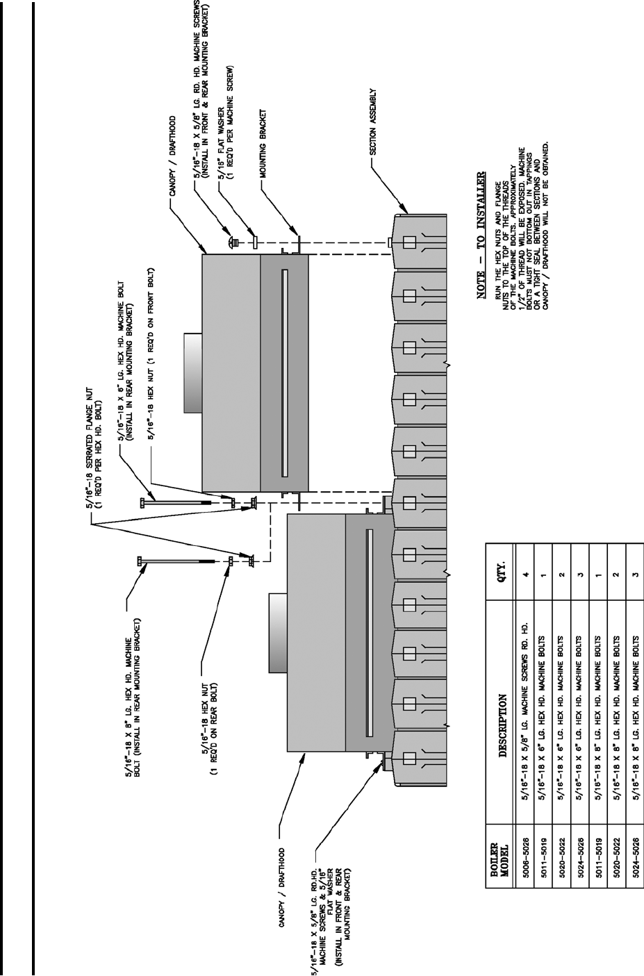
i. INSTALLATION OF CANOPY-DRAFT HOOD
5011B THRU 5026B SECTION BOILERS –
these boilers require two or more Canopy-Draft
Hoods – refer to Fig. 6 for proper arrangement.
Determine where ends of Canopy-Draft Hood
rest on intermediate sections. Place 1” x 14-1/2”
Cerafelt strips on top of intermediate section at
these locations. Place Cerafelt strips on top of
section assembly next to ledges formed by center
sections and next to ledges on end sections.
Overlap at corner.
ii. SECURE CANOPY-DRAFT HOODS with
machine screws and bolts as shown in Fig.
23. Select the type of fastener indicated and
drive them into the Tapped Lugs provided for
this purpose on top of the sections. Where two
Canopy-Draft Hoods join together, the securing
tabs will overlap.
iii. Attach the Front Intermediate Panel to the Front
Intermediate Panel Support Bracket(s), using
#10-32 x ½” self tapping screws.
29. INSTALLATION OF TOP FRONT JACKET PANELS
a. Remove knockout for supply piping. Refer to
recommended boiler piping diagrams in this manual.
b. Attach Top Front Jacket Panels to left and right end
Jacket Panels and also to top ange on the Vestibule
Panel using #8 SMS. Refer to Fig. 25 or 26.
30. PLACE TOP INTERMEDIATE PANEL(S) ON TOP
OF LEFT AND RIGHT PANELS, making sure that
Front Intermediate Panel(s) is under Top Intermediate
Panel(s). Secure Top Intermediate Panel using #8 SMS.
31. INSTALL KNOBS ON THE UPPER FRONT AND
UPPER REAR PANELS using #10-32 x 3/16” MS.
Install Upper Front, Lower Front, Upper Rear and
Lower Rear Panels using procedure we described in
detail “A” of Fig. 25 or 26.
SECTION III – INSTALLATION INSTRUCTIONS (continued)
29
FIG. 25
EXPLODED VIEW OF JACKET
5020B THRU 5022B SECT. BOILERS
SECTION III – INSTALLATION INSTRUCTIONS (continued)
Panel with louvers must be at front of boiler for
ventilation of vestibule. Panel with perforations
must be at front of boiler for ventilation and
combustion air.
30
FIG. 26
EXPLODED VIEW OF JACKET
5024B AND 5026B SECT. BOILERS
SECTION III – INSTALLATION INSTRUCTIONS (continued)
Panel with louvers must be at front of boiler for
ventilation of vestibule. Panel with perforations
must be at front of boiler for ventilation and
combustion air.
31
FIG. 27
STEAM TRIM AND CONTROLS
32. TIGHTEN ALL SHEET METAL SCREWS.
a. Install the following plates or labels which are found
in the Instruction Envelope. See Fig. 25 or 26 for
location.
(1) Rating Label
(2) Operating Instruction Plate (#8 SMS required to
fasten)
(3) Combustible Clearance Flooring & Adequate
Combustion Plate
(4) Minimum Service Clearance Label
(5) Burnham Logo – Apply to Top Panel
(6) Boiler Ventilation/For Your Safety Label
b. Proceed to Paragraph 33 (Steam Boilers) or
Paragraph 34 (Water Boilers).
NOTE: IF WATER BOILER, PROCEED DIRECTLY
TO Paragraph 34.
33. INSTALL STEAM TRIM AND CONTROLS, See
Fig. 7 and 27.
a. Pressure Gauge is to be installed with ½” nipple and
½” x ¼” reducing coupling in ½” tapping provided
in upper corner of End Section using wrench applied
to square shank on back of gauge. DO NOT APPLY
FORCE ON GAUGE CASE.
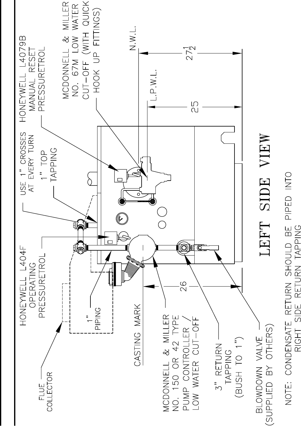
b. Install 67BC-2 Low Water Cut-Off or 47-2
Combination Feeder and Low Water Cut-Off in
accordance with the Instructions packed with the
control. ½” pipe extensions are provided and must
be installed in the ½” tappings adjacent to the
Pressure Gauge before the control can be mounted.
Unions are furnished with the 67BC-2 Low Water
Cut-Off for ease of installation. 1” pipe tappings
have been provided in the End Sections for other
types of Low Water Cut-Offs and Low Water Cut-
Off & Feeder combinations. Fig. 28 illustrates the
required mounting elevations for a M&M 150 and a
67M oat LWCO. Fig. 15 illustrates a typical steam
piping arrangement for pumped return systems.
c. Install Gauge Glass Fittings into ends of tees used
to connect the 67BC-2 or 47-2 Control. If other
control is furnished, install Gauge Glass Fitting
directly into ½” pipe extensions.
d. Install Pressure Limit Controls as follows:
(1) Boiler equipped with 67BC-2 Low Water Cut-
Off – Connect Pressure Limit furnished to ¼”
street ell and ¼” pigtail siphon. For installation
of second pressure limit (not furnished), bush
1½” pipe tapping in upper corner of End
Section. Connect Pressure Limit to this bushing
with ¼” pigtail siphon.
(2) Boiler equipped with Low Water Cut-Off other
than (1) above or with Low Water Cut-Off
Feeder Combination – Bush 1½” pipe tapping
in upper corner of End Section and connect
Pressure Limit furnished to this bushing with
¼” pigtail siphon. For installation of second
pressure limit bush any available tapping on
opposite end section that is above normal water
line. Connect Pressure Limit to this bushing
with ¼” pigtail siphon.
(3) Tighten limit controls by using wrench on hex
tting at bottom of control.
(4) The L404 Pressuretrol must be accurately
leveled for proper operation. It is level when the
leveling indicator hangs freely with its pointer
directly over the index mark inside the back
of the case. Level the controller by carefully
bending the steam trap (siphon loop).
e. Install Pressure Safety Valve with ttings furnished,
into 1½” pipe tapping in upper corner of End
Section, see Fig. 12. DO NOT INSTALL A
SHUTOFF VALVE BETWEEN SAFETY VALVE
AND BOILER. If this boiler tapping is to be used
as Surface Blowoff, replace ell with tee and plug
open end of tee or valve off opening. Pressure
Safety Valve must be in leg of tee and in a vertical
position with handle up.
f. Install Boiler Drain Valve and 3” x ¾” Bushing into
one of the two return tappings. The drain valve
may also be installed in return piping, but it must
be installed in the leg of a tee so that it is directly
opposite and as close as possible to the return
tapping. The leg of the tee must be at least 1½” pipe
size.
SECTION III – INSTALLATION INSTRUCTIONS (continued)
32
FIG. 28
MOUNTING ELEVATIONS OF M&M 150 AND A 67M FLOAT LWCO
SECTION III – INSTALLATION INSTRUCTIONS (continued)
33
A Bottom Blowoff using a valve must also be
connected to one of the return tappings. The ¾”
Drain Valve may be used for Bottom Blowoff for
5009B or smaller boilers, since any Bottom Blowoff
piping or valves for 5009B or smaller boilers must
be at least ¾”. Bottom Blowoff piping and valves
for Boilers 5010B through 5021B must be at least
1”. Bottom Blowoff piping and valves for 5022B
Boilers and larger must be at least 1¼”.
g. If boiler has been ordered with 3/8” try-valve
tapping, install try-cock.
h. Install “Lowest Permissible Water Level Plate”
and “Frequent Water Addition – Caution Label” on
upper left end jacket panel.
i. Proceed directly to Paragraph 36.
34. INSTALL WATER TRIM AND CONTROLS, see
Fig. 7 and 29.
a. Temperature Gauge is to be installed with ½”
nipple and ½” x ¼” reducing coupling in ½”
tapping provided in upper corner of End Section
using wrench applied to square shank on back of
gauge. DO NOT APPLY PRESSURE ON GAUGE
GLASS.
b. Install Temperature Limit Controls as follows:
Bush 1-1/2” tapping in upper corner of End Section
to ¾” and install Temperature Limit Control
furnished following instructions supplied with
control. On boilers without Built-in Tankless
Heater, install second temperature limit control (not
furnished) in Tapped Heater Opening Cover Plate.
FIG. 29
WATER TRIM AND CONTROLS
On boilers with Built-in Tankless Heater, install
operating control in ¾” tapping in Heater Plate-plug
tapping in Second Heater when supplied.
c. On boilers equipped for forced circulation hot
water heating without domestic hot water, a reverse
acting circulator control may be needed to prevent
condensation of ue gases during periods of low
boiler water temperature. This control can be
installed in the Tapped Heater Opening Cover Plate.
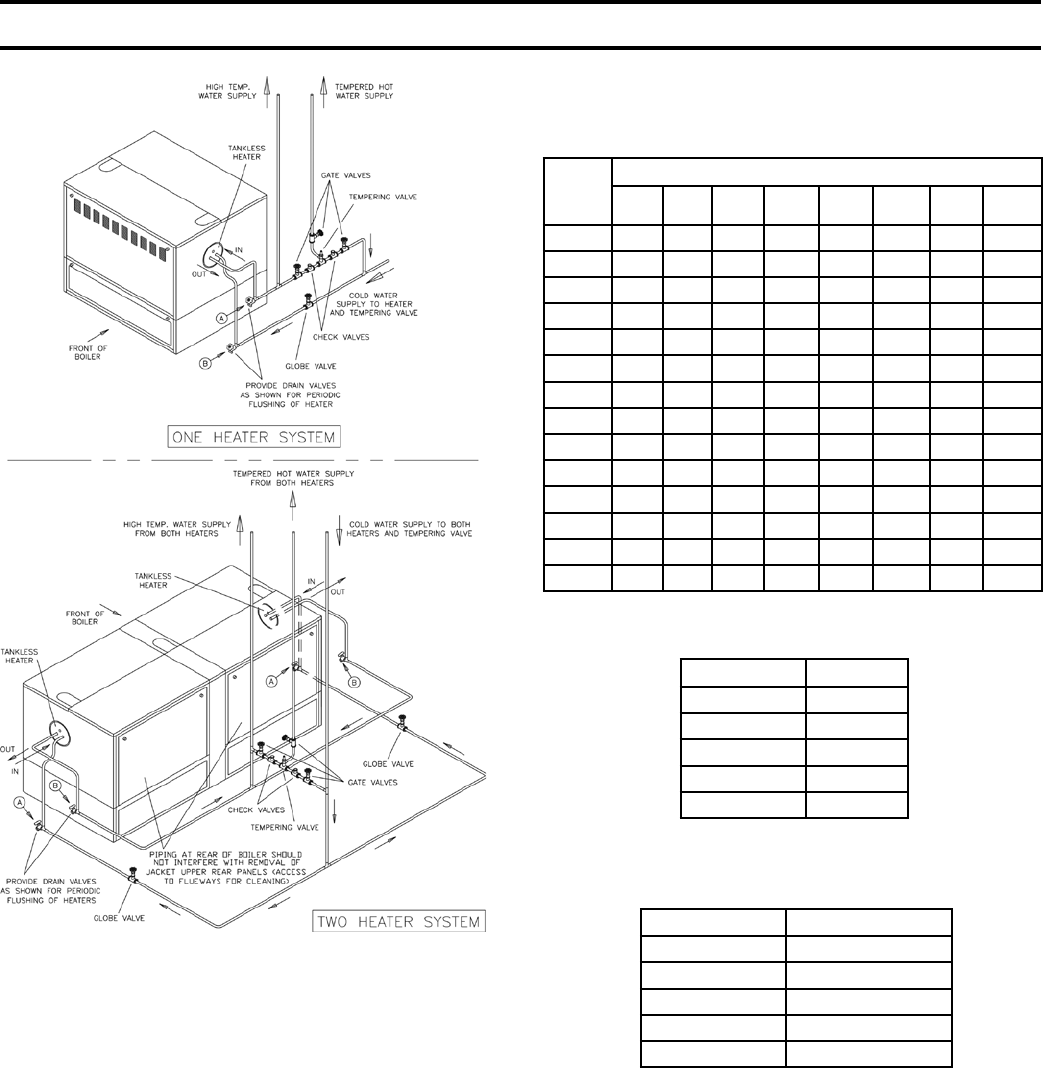
d. TANKLESS HEATER PERFORMANCE
Tankless heater ratings in Series 5B boilers are
based on continuous draw, temperature rise of 100ºF
(40-140ºF) and boiler water temperature of 200ºF.
Some of the items affecting the coil performance are
as follows:
(1) FLOW REGULATION – If ow through the
heater is greater than its rating, the supply of
adequate hot water may not be able to keep
up with the demand. For this reason a FLOW
REGULATOR matching the heater rating should
be installed in the cold water line to the heater.
(2) FLUSHING OF HEATER - All water contains
some sediment which settles on the inside of
the coil. Consequently, the heater should be
periodically back-washed. This is accomplished
by installing hose bibs as illustrated in Fig. 30
and allowing water at city pressure to run into
hose bib A, through the heater, and out hose bib
B until the discharge is clear. The tees in which
the hose bibs are located should be the same size
as heater connections to minimize pressure drop.
(3) HARD WATER – This is applicable to some
city water and particularly to well water. This
should not be a deterrent but precautions are
necessary. A water analysis is necessary and an
appropriate water softener installed. This is not
only benecial to the heater but to piping and
xtures plus the many other benets derived
from soft water.
NOTE: A hot water boiler installed above radiation
level must be provided with a low water cut-off
device as part of the installation.
Install automatic mixing valve at tankless heater
outlet to avoid risk of burns or scalding due to
excessively hot water at xtures. Adjust and
maintain the mixing valve in accordance with the
manufacturers instructions.
e. Following recommendations supplied with control,
install #64 Low Water Cut-Off in 1” pipe tapping
“H” (Fig. 7) and System Return Piping. Control
SECTION III – INSTALLATION INSTRUCTIONS (continued)
34
FIG. 30
RECOMMENDED PIPING TO
BUILT-IN TANKLESS HEATERS
TABLE I - NATURAL GAS
Maximum Capacity of Piping in Cubic Feet of Gas Per Hour
(Based on a Pressure Drop of 0.3” Water
and 0.6 Specic Gravity)
Pipe
Length
in Feet
NOMINAL IRON PIPE SIZE IPS INCHES
¾ 1 1¼ 1½ 2 2½ 3 4
10 278 520 1050 1600 3050 4800 8500 17500
20 190 350 730 1100 2100 3300 5900 12000
30 152 285 590 890 1650 2700 4700 9700
40 130 245 500 760 1450 2300 4100 8300
50 115 215 440 670 1270 2000 3600 7400
60 105 195 400 610 1150 1850 3250 6800
70 96 180 370 560 1050 1700 3000 6200
80 90 170 350 530 990 1600 2800 5800
90 84 160 320 490 930 1500 2600 5400
100 79 150 305 460 870 1400 2500 5100
125 72 130 275 410 78 1250 2200 4500
150 64 12 250 380 710 1130 2000 4100
175 59 110 225 350 650 1050 1850 3800
200 55 100 210 320 610 980 1700 3500
TABLE II
Multipliers to be used with Table I when Pressure Drop is not 0.3”
Pressure Drop Multiplier
0.1 .577
0.2 .815
0.5 1.29
1.0 1.83
0.3 1.00
TABLE III
Multipliers to be used with Tables I and II for
Specic Gravity Other than 0.60
Specic Gravity Correction Factors
.50 1.10
.55 1.04
.60 1.00
.65 .96
.70 .93
36. OPEN GAS TRAIN CARTON(S)
CONNECT GAS TRAIN(S) TO ELBOW ON END OF
MANIFOLD(S) according to the Gas Trains on pages
90 thru 96. On those boilers with two manifolds (15
sect. and larger), two identical sets of Gas Controls are
furnished. Hence, the procedure for installing one set is
equally applicable to the second set.
PRESSURE TESTING of gas service piping must be
done before connecting to the boiler gas train. Test for
leaks by introducing, from an isolated source, air or
inert gas to the piping. Piping shall withstand 3 PSI
gage pressure for a period of not less than 10 minutes
without showing any drop in pressure.
SECTION III – INSTALLATION INSTRUCTIONS (continued)
must be mounted so that cut off point is above
marking on Lowest Permissible Water Line Plate.
f. Install Pressure Safety Relief Valve, using ttings
furnished, into 1-1/2” pipe tapping in upper corner
of End Section. DO NOT INSTALL A SHUTOFF
VALVE BETWEEN SAFETY RELIEF VALVE
AND BOILER. Safety Relief Valve must be
installed in a Vertical Position with handle up.
g. Install Boiler Drain Valve into one of unused return
tappings that has been bushed to ¾”. Drain Valve
can also be installed in return piping, preferably
in leg of tee that is located in line with return
connection on Boiler.
35. CONNECT PIPING TO BUILT-IN HEATER(S) IF
USED, see Fig. 30, top - left side of this page.

35
38. THE INSTALLATION OF THE REMAINDER OF THE GAS CONTROLS IS DEPENDENT ON THE CONTROL
SYSTEM FURNISHED. REFER TO THE TABLE BELOW FOR THE FIGURES IN THIS MANUAL APPLICABLE
TO THE VARIOUS CONTROL SYSTEMS OFFERED AS STANDARD OR AS OPTIONAL EQUIPMENT. IF THE
CONTROL SYSTEM ORDERED IS NOT LISTED, SPECIAL INSTRUCTIONS HAVE BEEN PREPARED BY THE
APPLICATION ENGINEERING DEPARTMENT AND CAN BE FOUND IN THE INSTRUCTION ENVELOPE
FURNISHED WITH THE BOILER.
BOILER SIZE CONTROL
SYSTEM
NATURAL GAS LP
REFERENCE
FIGURES
USA CANADA USA CANADA
STD OPT STD OPT STD OPT STD OPT
6 thru 9 sect. EI X --- --- X X --- --- --- 31, 32
10 thru 26 sect. EI X --- --- X --- --- --- --- 31, 33
6 thru 26 sect. EI --- X --- --- --- --- 31, 33
6 thru 14 sect. EP --- X --- X --- --- --- --- 34, 35
15 thru 26 sect. EP --- X --- X --- --- --- --- 34, 35
6 thru 13 sect. Thermocouple --- --- X --- --- --- --- --- 36, 37
15 thru 24 sect. Thermocouple --- --- X --- --- --- --- --- 36, 37
37. A DRIP LEG SHOULD BE PROVIDED IN THE
VERTICAL DROP TO EACH GAS TRAIN, see
Fig. 1. An additional Manual Shut-off valve and
ground joint union, as show in Fig. 1, should be
installed in the piping to each gas train for ease of
servicing.
CONNECT GAS SERVICE FROM METER TO GAS
TRAIN in accordance with the requirements of the
authority having jurisdiction or, in the absence of such
requirements to the –
USA – “National Fuel Gas Code, ANSI Z223.1”.
CANADA – “Installation Codes for Natural and LP Gas
Burning Appliances and Equipment, CAN/B149.1 &
.2”.
The size of the gas train(s) has no criteria as to the size
of the service from the meter to the gas train(s). Sizing
of the service is dependent on:
a. Required supply of gas in cu. ft./hr.
input of boiler in BTUH
= heat value of gas,
BTU/cu. ft.
b. Allowable loss of pressure in piping to obtain
minimum input pressure indicated on rating label of
boiler.
c. Length of piping in feet and number of elbows – for
practical purposes each 90º elbow can be considered
as the following equivalent in length of straight
pipe:
3/4” - 2.1 ft. 2” - 5.2 ft.
1” - 2.6 ft. 2-1/2” - 6.2 ft.
1-1/4” - 3.5 ft. 3” - 7.7 ft.
1-1/2” - 4.0 ft. 4” - 10.1 ft.
d. Specic gravity of gas
In the absence of requirements of the authority
having jurisdiction, the tables below may be used to
size natural gas supply piping.
A pipe thread compound resistant to the action
of liqueed petroleum gases must be used on all
threaded joints in the gas piping.
Pressure testing of the Gas Supply Piping Boiler and
its connections is required before placing the boiler
in operation.
The boiler and shutoff valve must be disconnected
from the gas supply piping system during any
pressure testing at pressures greater than ½” psig.
The boiler must be isolated from the gas supply
piping system during any pressure testing at
pressures equal to or less than ½ psig.
WITH GAS SUPPLY “OFF” and Service Piping
connected to the boiler, open Manual Valve(s) and
pilot valve(s) at end of Gas Train(s) and reduce
pressure to ½ lb. gage pressure. Using soap solution
or other approved method check gas train piping,
pilot piping, bleed piping and orices for leaks.
SECTION III – INSTALLATION INSTRUCTIONS (continued)

36
FIG. 31
INSTALLATION OF S8610M MODULE
EI Control System
1. INSTALLATION OF GAS VALVE TRANSFORMER
AND PILOT PIPING (for Robertshaw Pilot Piping,
see Fig. 32) – Attach the bracket for mounting of the
junction box to the lower front corner of the Jacket
Upper End Panel using two #10-32 x ½” MS and nuts.
Mount junction box to bracket using #8 SMS, see Fig.
27 or 29. Connect pilot solenoid valve to bottom center
knockout of J-box using conduit ttings furnished,
(V88 Gas Train only) see Fig. 33. Mount transformer
on J-box. If Foot Mounted Transformer, connect to
J-box with Straight Connector, BX, Straight Connector
and ½” pipe coupling. Drill holes in Jacket and fasten
Transformer using SMS. Install RV-12LT pilot line
regulator (packed in Gas Train Carton) and other 1/8”
pipe ttings as shown in Section VI, Repair Parts (V88
Gas Train only).
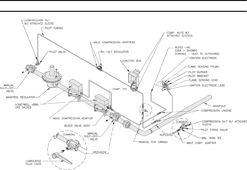
Using ¼” OD aluminum tubing, connect the inlet of
the pilot solenoid valve to the pilot valve installed in
the manual shut off valve in the Gas Train. Using ¼”
aluminum tubing, complete installation to Pilot Burner,
see Fig. 33 (V88 Gas Train only).
2. INSTALLATION OF BLEED PIPING (V88 Gas Train
only) – Using ¼” OD aluminum tubing, install a bleed
line on both diaphragm gas valves, connect together,
and, on USA boilers, run tubing to bleed line protruding
from inside base, see Fig. 33. On boilers installed in
Canada, run bleed line to outdoors.
3. INSTALLATION AND WIRING OF S8610M
IGNITION CONTROL MODULE – Using two #10-32
x 2” MS, and nuts, install the S8610M module bracket
on the manifold just to the right of the main burner
SECTION III – INSTALLATION INSTRUCTIONS (continued)
with pilot, see Fig. 31. Using two #6 x ¾” SMS, install
the S8610M module on the bracket. Connect the two
wires from the Q3481B pilot to the S8610M module as
shown on Fig. 40, 41 or 42.
a. Ground Wire (200ºC) to “BNR GND” terminal
b. Ignition Sensor Wire to “Spark” terminal
Secure these wires to Pilot Piping with Wire Tie to
provide strain relief.
Using wiring harness furnished, connect leads with
push-on terminals on S8610M module as shown in
Fig. 40, 41 or 42. Run harness outside of jacket on
underside of manifold and secure in this position
with Wire Ties furnished. Connect the six wires in
the harness to the specied controls as shown in Fig.
40, 41 or 42.
FIG. 32
PILOT PIPING - EI CONTROL SYSTEM
(Robertshaw7000)
U.S.A. 5006B THRU 5009B
37
FIG. 33
PILOT PIPING - EI CONTROL SYSTEM (V88A)
U.S.A. 5010B THRU 5026B - NAT. GAS
CANADA - 5006B THRU 5026B - NAT. GAS
4. COMPLETION OF WIRING – Connect power supply
fused disconnect switch, service switch, primary side
of transformer, gas valves and remaining controls – see
Fig. 40, 41 or 42 for wire type and connections to be
made. All wiring must be adequately supported and
strain relief provided. All wiring including ground
connections must comply with the requirements of
the authority having jurisdiction and, in the absence
of such, to the National Electrical Code, ANSI NFPA
No. 70-2005, or the Canadian Electrical Code, C22.1,
whichever is applicable.
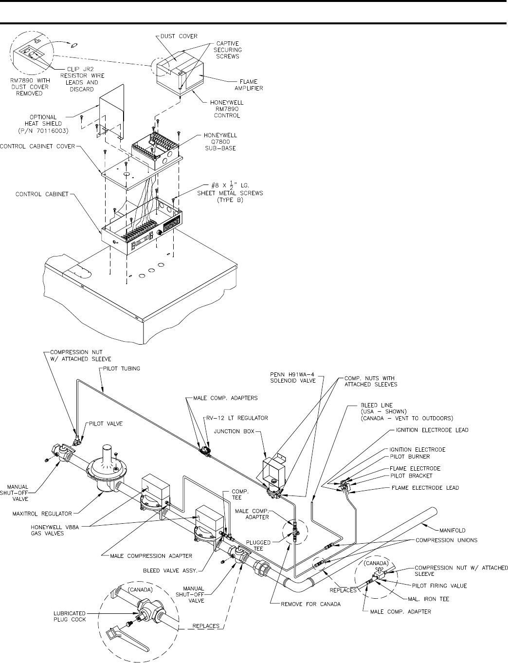
EP Control System
1. INSTALLATION OF “EP PANEL”, - Attach the EP
Control Panel with RM7890 control, see Fig. 34, to the
front top jacket panel, preferably on the closest jacket
panel to the gas train installed. There are (3) three KO’s
and (4) four fastening holes provided for this purpose,
use (4) four #8 SMS to fasten the Control Panel to the
front top jacket panel. If Foot Mounted Transformer,
connect to J-box using straight connector, BX, straight
connector and ½” pipe nipple. Drill holes in Jacket
and fasten Transformer using SMS. Install Honeywell
SECTION III – INSTALLATION INSTRUCTIONS (continued)
RM7890 Control (located in RM7890 Control Carton)
onto prewired sub base.
Remove RM7890’s Dust Cover. With a pair of side
cutters, carefully snip both wire leads to the brown
resistor labelled “JR2” and discard it. Replace Dust
Cover. Install Honeywell R7847 Flame Amplier.
Install heat shield (optional).
2. INSTALLATION OF PILOT PIPING – Install the
H91WA-4 pilot solenoid valve in the bottom center
knockout of the J-box using conduit ttings furnished,
see Fig. 35. Install RV-12LT regulator, (Packed in Gas
Train Carton) and 1/8” tee in the ¼” OD pilot tubing as
shown in Fig. 35.
3. INSTALLATION OF BLEED PIPING – Using ¼” OD
aluminum tubing, install a bleed line on both diaphragm
valves, connect together, see Fig. 35, and, on USA
boilers, run tubing to bleed line protruding from inside
base, see Fig. 35. On boilers installed in Canada, run
bleed line to outdoors.
38
SECTION III – INSTALLATION INSTRUCTIONS (continued)
FIG. 34
INSTALLATION OF EP CONTROL PANEL
FIG. 35
PILOT PIPING - EP CONTROL SYSTEM
NOTE - PILOT PIPING DUPLICATED ON
15 SECT. AND LARGER BOILERS.

39
4. INSTALLATION OF IGNITION TRANSFORMER
AND WIRING OF PILOT – If space permits, mount
the ignition transformer on the Jacket above the Gas
Train using four #8 x ½” SMS. Holes will have to
be drilled for this purpose. If space does not permit
mounting the Ignition Transformer on the Jacket, install
the Ignition Transformer on a nearby wall.
Connect the two wires from the Q179C pilot to the
RM7890 sub-base as follows:
a. Ground Wire (200ºC) to the “12” terminal
b. Flame detector wire (Honeywell 1298020) to “11”
terminal
c. Ignition Cable (Honeywell 1061012) to the
Secondary (High Voltage) terminal of the Ignition
Transformer
Run these wires to outside of jacket on underside of
manifold and secure in this position with Wire Ties
furnished to provide strain relief. Provide adequate
support and strain relief for wiring outside jacket.
5. COMPLETION OF WIRING – Connect power supply
fused disconnect switch, service switch, primary and
secondary side of gas valve transformer, primary side
of ignition transformer, and remaining controls – see
Fig. 44 for wire type and connections to be made. All
wiring must be adequately supported and strain relief
provided. All wiring including ground connections
must comply with the requirements of the authority
having jurisdiction and, in the absence of such, to the
National Electrical Code, ANSI NFPA No. 70-2005,
or the Canadian Electrical Code, C22.1, whichever is
applicable.
Thermocouple Control System
1. INSTALLATION OF PILOT SAFETY SWITCH AND
PILOT PIPING - Using two #10-32 x 2” MS and nuts,
install the L62GB-3C pilot safety switch bracket on
the manifold just to the right of the main burner with
pilot. Install L62GB-3C pilot safety switch on bracket
using two #10-32 x ½” MS. “IN” on pilot safety switch
should be pointed in the direction of the Gas Train to
which the pilot safety switch is to be connected, see
Fig. 37.
Using ¼” OD aluminum tubing, connect the pilot
shutoff valve installed in the manual shutoff valve
in the gas train, to the inlet of the RV-12LT regulator
(packed in Gas Train Carton). Regulator should be
above Gas Train and near front of boiler, see Fig. 36.
Install 3/8” tee into outlet of regulator (USA boilers)
and, using ¼” OD aluminum tubing, connect outlet of
tee to “IN” connection on pilot safety switch, see Fig.
36.
Using ¼” OD aluminum tubing, connect the outlet of
the pilot safety switch to the tubing or tting connected
to the pilot burner, see Fig. 36.
Connect Q309 thermocouple to pilot safety switch.
Connect power supply fused disconnect switch,
service switch, primary and secondary of Gas Valve
Transformer, gas valves, and other controls - see Fig’s
46 and 47 for wiring type and connections to be made.
All wiring must be adequately supported and strain
relief provided.
All wiring including ground connections must
comply with the requirements of the authority having
jurisdiction and, in the absence of such to the National
Electrical Code, ANSI NFPA No. 70-2005.
2. INSTALLATION OF GAS VALVE TRANSFORMER
AND COMPLETION OF WIRING - Attach the bracket
for mounting of the junction box to the lower front
corner of the Jacket Upper End Panel using two #10-
32 x ½” MS and nuts. Mount junction box to bracket
using #8 SMS, see Fig. 36. Install Transformer on
junction box.
SECTION III – INSTALLATION INSTRUCTIONS (continued)
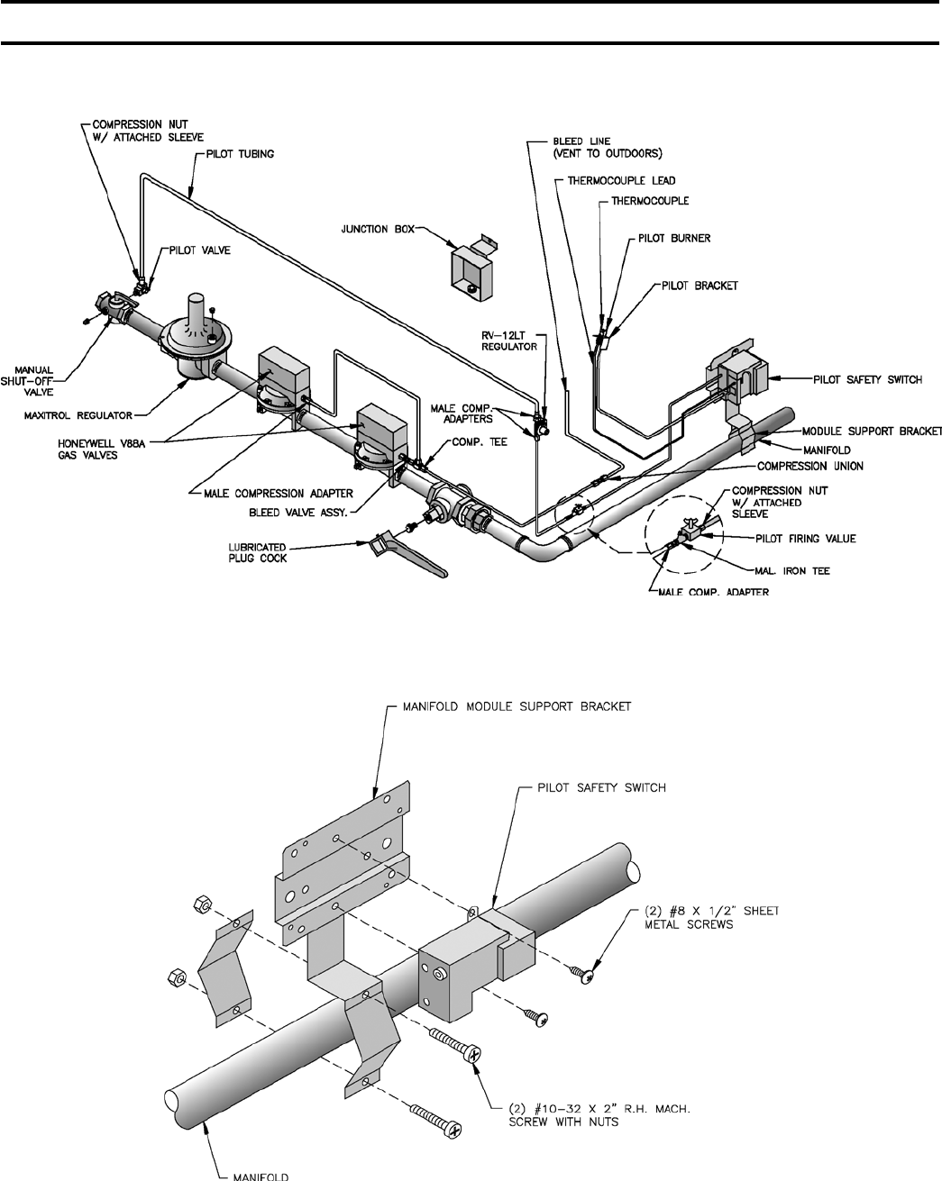
40
“THERMOCOUPLE CONTROL SYSTEM”
CANADA ONLY
FIG. 36
PILOT PIPING
THERMOCOUPLE CONTROL SYSTEM
CANADA ONLY
FIG. 37
NOTE - TWO PILOT SAFETY SWITCHES REQUIRED ON 15 SECT. AND LARGER BOILERS.
INSTALLATION OF PILOT SAFETY SWITCH
THERMOCOUPLE CONTROL SYSTEM
SECTION III – INSTALLATION INSTRUCTIONS (continued)
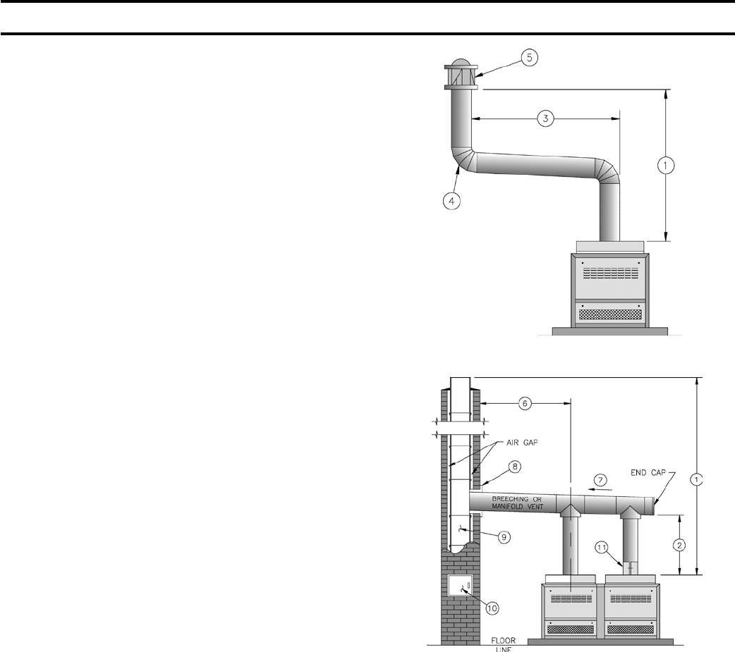
41
Venting
1. INSTALL VENT CONNECTOR from canopy Draft
Hood or damper to chimney maintaining 6” clearances
from combustible materials.
2. INSTALL VENT SYSTEM – Typical vent systems are
shown in Fig. 38 and 39. Some of the factors affecting
vent sizing and construction accompany these gures.
Vent installation shall be in accordance with local
building codes; or the local authority having
jurisdiction; or the National Fuel Gas Code, ANSI
Z223.1/NFPA 54; or the Standard for Chimneys,
Fireplaces, Vents and Solid Fuel Burning Appliances,
ANSI/NFPA 211. Both of the aforementioned
standards, ANSI Z223.1 and ANSI/NFPA 211,
specify Type B and Type L double wall metal vents
and re clay tile lined masonry chimneys as suitable
chimney constructions for Category I, draft hood
equipped appliances, such as this Series 5B boiler.
Both standards prohibit the use of unlined masonry
construction as a chimney, with the exception in
ANSI Z223.1/NFPA 54 that “Where permitted by
the authority having jurisdiction, existing chimneys
shall be permitted to have their use continued when
an appliance is replaced by an appliance of similar
type, input rating and efciency.” ANSI/NFPA 211
prohibits the use of single wall metal vent as a chimney,
while ANSI Z223.1 allows it under very restrictive
conditions.
In Canada, refer to CAN/CSA-B149.1 or .2-M86 and
local codes for venting.
SOME ITEMS RELATIVE TO CONSTRUCTION
AND SIZING OF VENT SYSTEM
(1) Total Vent Height.
(2) Vent Connector – make Initial Rise as high as
possible.
(3) Length of Lateral – hold to a minimum.
(4) Number of Elbows – hold to a minimum.
(5) UL Listed Vent Cap – assures full vent capacity
and freedom from adverse wind effects.
(6) Locate Boiler as close to Chimney as possible
consistent with necessary clearances, see page 10,
lower table.
(7) Run Breaching Horizontal and slope upward to
Chimney maximum of ¼” per ft.
(8) Use thimble where Breaching enters masonry
chimney – keep breaching ush with inside of ue
liner – do not connect into same leg of chimney
serving an open replace.
(9) Install vent above bottom of Chimney to prevent
blockage – inspect chimney for obstructions
or restrictions and remove – clean chimney if
necessary.
FIG. 38
SINGLE VENT SYSTEM
FIG. 39
MANIFOLD VENT SYSTEM
(10) Provide cleanout in chimney.
(11) Slip joint or draw band – facilitates installation and
future servicing when necessary.
(12) Venting of other appliances into same chimney
or into a common vent will affect sizing of the
chimney or common vent.
(13) Correction for altitude – design vent system for sea
level input.
(14) Provide adequate ventilation of Boiler Room, see
page 10 – this cannot be overemphasized.
(15) Never pass any portion of a vent system thru a
circulating air duct or plenum.
(16) Support of lateral runs so that vent pipe does not
sag.
(17) Support of common vent where it passes thru a
ceiling or roof.
SECTION III – INSTALLATION INSTRUCTIONS (continued)

42
(18) Clearances to combustible material – use of
thimbles.
(19) Firestops.
(20) Flashing and storm collars.
(21) Guying or bracing of common vent pipe above
roof.
(22) Securing and gas tightness of joints.
(23) Lightning arrester if top of metal vent is one of
highest points on the roof.
Where choice is possible, many advantages can be
listed for the UL Listed double wall metal type B vent:
1. Warm up is faster with type B vents than vents
having greater mass.
2. Type B vents permit closer clearance to
combustible material than single wall metal
vents unless special precautions are taken with
the latter.
3. Type B vents are less prone to condensation and
corrosion than single wall metal vents.
4. Type B vents are lightweight, easy to handle and
assemble.
SECTION III – INSTALLATION INSTRUCTIONS (continued)
WHEN AN EXISTING BOILER IS REMOVED FROM A COMMON VENTING SYSTEM, THE COMMON VENTING
SYSTEM IS LIKELY TO BE TOO LARGE FOR PROPER VENTING OF THE APPLIANCES REMAINING CONNECTED
TO IT. AT THE TIME OF REMOVAL OF AN EXISTING BOILER, THE FOLLOWING STEPS SHALL BE FOLLOWED
WITH EACH APPLIANCE REMAINING CONNECTED TO THE COMMON VENTING SYSTEM PLACED IN OPERATION,
WHILE THE OTHER APPLIANCES REMAINING CONNECTED TO THE COMMON VENTING SYSTEM ARE NOT
IN OPERATION.
A. SEAL ANY UNUSED OPENINGS IN THE COMMON VENTING SYSTEM.
B. VISUALLY INSPECT THE VENTING SYSTEM FOR PROPER SIZE AND HORIZONTAL PITCH AND DETERMINE
THERE IS NO BLOCKAGE OR RESTRICTION, LEAKAGE, CORROSION AND OTHER DEFICIENCIES WHICH
COULD CAUSE AN UNSAFE CONDITION.
C. INSOFAR AS IS PRACTICAL, CLOSE ALL BUILDING DOORS AND WINDOWS AND ALL DOORS BETWEEN
THE SPACE IN WHICH THE APPLIANCES REMAINING CONNECTED TO THE COMMON VENTING SYSTEM
ARE LOCATED AND OTHER SPACES OF THE BUILDING. TURN ON CLOTHES DRYER AND ANY APPLIANCE
NOT CONNECTED TO THE COMMON VENTING SYSTEM. TURN ON ANY EXHAUST FANS, SUCH AS
RANGE HOODS AND BATHROOM EXHAUSTS, SO THEY WILL OPERATE AT MAXIMUM SPEED. DO NOT
OPERATE A SUMMER EXHAUST FAN. CLOSE FIREPLACE DAMPERS.
D. PLACE IN OPERATION THE APPLIANCE BEING INSPECTED. FOLLOW THE LIGHTING INSTRUCTIONS.
ADJUST THERMOSTAT SO APPLIANCE WILL OPERATE CONTINUOUSLY.
E. TEST FOR SPILLAGE AT THE DRAFT HOOD RELIEF OPENING AFTER 5 MINUTES OF MAIN BURNER
OPERATION. USE THE FLAME OF A MATCH OR CANDLE, OR SMOKE FROM A CIGARETTE, CIGAR OR
PIPE.
F. AFTER IT HAS BEEN DETERMINED THAT EACH APPLIANCE REMAINING CONNECTED TO THE COMMON
VENTING SYSTEM PROPERLY VENTS WHEN TESTED AS OUTLINED ABOVE, RETURN DOORS, WINDOWS,
EXHAUST FANS, FIREPLACE DAMPERS AND OTHER GAS BURNING APPLIANCE TO THEIR PREVIOUS
CONDITIONS OF USE.
G. ANY IMPROPER OPERATION OF THE COMMON VENTING SYSTEM SHOULD BE CORRECTED SO THE
INSTALLATION CONFORMS WITH THE NATIONAL FUEL GAS CODE, ANSI Z223.1. WHEN RESIZING ANY
PORTION OF THE COMMON VENTING SYSTEM, THE COMMON VENTING SYSTEM SHOULD BE RESIZED
TO APPROACH THE MINIMUM SIZE AS DETERMINED USING THE APPROPRIATE TABLES IN CHAPTER
10 IN THE NATIONAL FUEL GAS CODE, ANSI Z223.1.

43
SECTION IV - OPERATION
Safe lighting and other performance criteria were met with the gas manifold and control assembly provided on the boiler
when the boiler underwent tests specied in ANSI Z21.13.
1. GENERAL
a. INITIAL FILL – Before putting water into a new
boiler, make certain that the ring equipment is in
operating condition to the extent that this is possible,
without actually ring into an empty boiler. This
is necessary because raw water must be boiled
[or heated to at least 180ºF] promptly after it is
introduced into the boiler in order to drive off the
dissolved gases which might otherwise corrode the
boiler.
b. PURGE GAS PIPING OF AIR – Check Manual
Shut Off Valve(s) and Pilot Shut Off Valve(s) at
boiler to see that they are closed. Turn gas on
at meter. Disconnect Pilot Tubing at Pilot Shut
Off Valve(s), open Pilot Valve(s) until gas ows
from valve(s) KEEPING A CONSTANT CHECK
DURING THE PURGING. Close pilot valve(s)
and reconnect the pilot tubing. (In Canada, refer
to applicable Installation Codes for purging
procedure.)
c. SINCE LIGHTING INSTRUCTIONS,
SHUTDOWN INSTRUCTIONS, AND CONTROL
SEQUENCE OF OPERATION VARY WITH
GAS CONTROL SYSTEM INSTALLED,
REFERENCE SHOULD NEXT BE MADE TO
THE APPLICABLE CONTROL SYSTEM:
wasted, operate boiler only for the length of time it
takes for condensate to run clear. If the latter cannot
be achieved or if the condensate is returned to the
boiler, boil out the boiler using the surface blowoff
connection. See Fig. 7.
a. Drain boiler until water is just visible in gauge
glass. Run temporary 1½” pipe line from the
surface blowoff connection to an open drain or
some other location where hot water may be
discharged safely. Do not install valve in this
line.
b. Add an appropriate amount of recommended boil
out compound.
c. Start burner and operate sufciently to boil
the water without producing steam pressure.
Boil for about 5 hours. Open boiler feed pipe
sufciently to permit a steady trickle of water
from the surface blowoff pipe. Continue this
slow boiling and trickle of overow for several
hours until the water coming from the overow
is clear.
d. Stop burner and drain boiler in a manner and to
a location that hot water can be discharged with
safety.
e. Rell boiler to normal water line. If water in
gauge glass does not appear to be clear, repeat
steps (a. through c.) and boil out the boiler for a
longer time.
2. Low pressure steam boilers such as the 5B series
should be maintained with appropriate water
treatment compounds. Add suitable water treatment
compounds as recommended by your qualied water
treatment company.
3. Remove temporary surface blowoff piping, plug
tapping and reinstall safety valve. Boil or bring
water temperature to 180ºF promptly in order to
drive off the dissolved gases in the fresh water.
4. If unsteady water line, foaming or priming persist,
install gate valve in Hartford Loop and drain valves
in return main and at boiler and proceed as follows:
a. Connect hoses from drain valves to oor drain.
Close gate valve in Hartford Loop and open
drain valve in return main. Fill boiler to normal
water level, turn on burner and operate boiler
at this water level for at least 30 minutes after
the condensate begins to run hot, then turn off
burner.
Close all radiator valves. Remove all supply
main air valves and plug the openings in supply
main.
EI Control System - Page 46
EP Control System - Page 52
THERM Control System - Page 57
Check all electrical circuits and connections. Then
follow lighting instructions up to a point where the
boiler is ready to light.
2. BOILER AND SYSTEM CLEANING
INSTRUCTIONS FOR TROUBLE FREE
OPERATION
A qualied water treatment chemical specialist
should be consulted for recommendations regarding
appropriate chemical compounds and concentrations
which are compatible with local environmental
regulations.
A. Steam Boilers
1. Oil, greases & sediments which accumulate in a
new boiler and piping must be removed in order
to prevent an unsteady water line and carry over
of the water into the supply main above boiler.
Operate the boiler with steam in the entire system
for a few days allowing the condensate to return
to the boiler. If the condensate can temporarily be
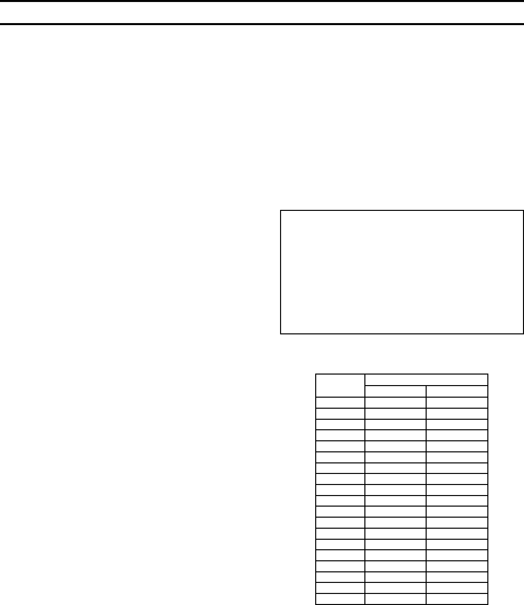
44
b. Draw about 5 gallons of hot water from
boiler into a container and dissolve into it the
appropriate amount of a recommended boilout
compound. Remove safety valve from boiler
and pour this solution into boiler, then reinstall
safety valve.
c. Turn on burner and keep operating while feeding
water to boiler slowly. This will raise water
level in boiler slowly into supply main and back
through return main, owing from drain hose
at about 180ºF. Continue until water runs clear
from drain hose for at least 30 minutes.
d. Stop feeding water to boiler but continue
operating burner until excess water in boiler
ows out through supply main and water lowers
(by steaming) until it reaches normal level in
boiler.
Turn off burner. Drain boiler. Open all radiator
valves. Reinstall all supply main air valves.
Open gate valve in Hartford Loop.
e. When boiler has cooled down sufciently
(crown-sheet of sections are not too hot to
touch), close the drain valves at boiler and in
return main and feed water slowly up to normal
level in boiler. Turn on burner and allow boiler
to steam for 10 minutes, then turn off burner.
Draw off one quart of water from bottom gauge
glass tting and discard. Draw off another quart
sample and if this sample is not clear, repeat the
cycle of draining the boiler and return main and
relling the boiler until sample is clear.
f. If the boiler water becomes dirty again at a later
date due to additional sediment loosened up in
the piping, close gate valve in Hartford Loop,
open drain valve in return main, turn on burner
and allow condensate to ow to drain until it has
run clear for at least 30 minutes while feeding
water to boiler so as to maintain normal water
level. Turn off burner, drain boiler, open gate
valve in Hartford Loop, then repeat step 1 above.
3. Make pH or Alkalinity Test
After boiler and system have been cleaned and
relled as previously described, test the pH of
the water in the system. This can easily be done
by drawing a small sample of boiler water and
testing with Hydrion paper which is used in the
Boiler Size Water Content (Gallons)
Water Boiler Steam Boiler
5006B 37.6 25.6
5007B 43.4 29.3
5008B 49.1 33.0
5009B 54.9 36.8
5010B 60.6 40.5
5011B 66.4 44.2
5012B 72.1 47.9
5013B 77.9 51.6
5014B 83.7 55.4
5015B 89.4 59.1
5016B 95.2 62.8
5017B 100.9 66.5
5018B 106.7 70.2
5019B 112.5 73.9
5020B 118.2 77.7
5021B 124.0 81.4
5022B 129.7 85.1
5024B 141.2 92.5
5026B 152.8 100.0
TABLE IV: WATER CONTENT
SECTION IV - OPERATION (continued)
Recommended Water Quality Requirements
pH: 8.3 - 10.5
TDS: < 3500 ppm
Total alkalinity ppm as CaCO3 : < 1200
Total copper ppm: < .05
Oily matter ppm: < -1
Total harness ppm: < -3
Chlorides: < 50 ppm
same manner as litmus paper, except that it gives
specic readings. A color chart on the side of
the small hydrion dispenser gives the reading in
pH. Hydrion paper is inexpensive and obtainable
from any chemical supply house or through your
local druggist. The pH should be in accordance
to “Minimum Water Quality Requirements” chart
below. Add some washout chemicals (caustic soda),
if necessary, to bring the pH within the specied
range. With this lower level of protection, care must
be exercised to eliminate all of the free oxygen in
the system.
4. Boiler is now ready to be put into service.
45
3. CONDENSATION
Following a cold start, condensation (sweating) may
occur in a gas red boiler to such an extent that it
CONTROL VARIATIONS
NATURAL GAS
MODEL NO. CONTROL
SYSTEM
TYPE OF
PILOT
GAS VALVES OPTIONAL MAIN
VALVES
REFERENCE
PAGE
PILOT MAIN
5006B-5009B (USA) EI Elec. Ign. (1) 7000DERHC-S7C (B) 47
5010B-5026B (USA)
5006B-5026B (CANADA) EI Elec. Ign. (1) H91WG-6 (2) V88A (B)** 48-50
5008B-5026B
(USA & CANADA) EP Elec. Ign. Q179C (1) H91WA-4 (2) V88A (A), (B)* 54 & 55
5006B-5013B (CANADA) 24V Standing (1) L62GB-3C (2) V88A (A), (B) 58
5015B-5024B (CANADA) 24V Standing (1) L62GB-3C (2) V88A (A), (B) 59
LP GAS
MODEL NO. CONTROL
SYSTEM
TYPE OF
PILOT
GAS VALVES OPTIONAL MAIN
VALVES
REFERENCE
PAGE
PILOT MAIN
5006B-5009B (USA) EI Elec. Ign. (1) 7000DERHC-S7C 47
(A) -- (1) Honeywell V5055B Motorized Gas Valve with V4055A/V4062A/V9055A Actuator and (1) ITT K3A
Solenoid Valve (120V)
(B) -- (1) Honeywell V8944B Combination Gas Valve and (1) ITT K3A Solenoid Valve (24V)
* -- To be used with (1) H91WA-4 Pilot Valve (120V)
** -- To be used with (1) H91WG-6 Pilot Valve (24V)
NOTE:
1. For Steam or Water
2. For 24V Thermostat Application - Wire S861OM Relay in Place of Operating Control Set Thermostat Heat
Anticipator at 0.4 Amp. See Pages 47, 48 and 49.
3. All Battery Operated Thermostats must be Electrically Isolated From the Primary Circuit by an Isolating Relay.
appears that the boiler is leaking. This condensation
can be expected to stop after the boiler is hot.
SECTION IV - OPERATION (continued)

46
4. EI CONTROL SYSTEM – The EI control system
utilizes a solid state ignition control which lights the
pilot burner by spark. Pilot gas is ignited and burns
during each running cycle (intermittent electric pilot).
Main burner and pilot gas are extinguished during the
“off” cycle.
This system permits the main gas valves
[Robertshaw7000 for 5006B thru 5009B, (2) V88A’s
for 5010B thru 5014B] to open, and the pilot line gas
valve to remain open, only when the Pilot Burner is
proven to be lit.
Should a loss of ame occur, the main valve closes
and the spark reoccurs within 0.8 second. The ignition
module has an internal 100% lockout function to
completely shutdown the system should the pilot gas
fail to ignite within approximately 90 seconds. Five to
six minutes after shutdown, the Ignition Module restarts
the ignition sequence. The ignition trial, shutdown, and
wait sequence continues until either the pilot lights or
the Thermostat is set below room temperature (to end
the call for heat). The ignition sequence can be reset by
setting down the Thermostat for one minute.
a. OPERATING INSTRUCTIONS
(1) Make sure all Manual Main Shut-off Valves and
all Pilot Valves have been off for at least ve
minutes.
(2) Set Operating and Limit Controls to desired
settings.
(3) Turn all Manual Main Shut-Off Valves and Pilot
Valves to Open Position.
(4) Turn on Main Electric Switch and Service
Switch – Pilot(s) will automatically light main
burners.
b. NORMAL OPERATION SEQUENCE
5006B thru 5009B, see Fig. 40
5010B thru 5014B, see Fig. 41
5015B thru 5026B, see Fig. 42
c. SHUT DOWN INSTRUCTIONS
(1) Close manual shut-off valves and pilot valves.
(2) Turn off main electric switch.
d. SAFETY SHUTDOWN
(1) Safety Switch Circuit
If limit control, low water cut-off or any other
electrical safety switch opens, power to the 24V
terminal of all S8610M Ignition Controls is
interrupted thus de-energizing terminals PV and
MV. Loss of power to these terminals means
loss of power to all pilot gas valves and to main
gas valves, respectively. Thus, pilot burner and
main burner ames are extinguished.
Normal operation can be resumed when the
cause of safety switch malfunction is corrected.
Any controls with Manual Reset must be
reactivated.
(2) Pilot Failure
Pilot failure can occur during the start-up or
during the operating cycle of the boiler. Any
failure of a Q3481B pilot will close the main
gas valves controlled by this pilot within 0.8
second. For 90 seconds after pilot failure, the
Ignition Control will try to reestablish pilot
ame. If the pilot ame cannot be sensed by
the sensing probe, the module will lock out
on safety. Five to six minutes after shutdown,
the IGNITION MODULE restarts the ignition
sequence. The ignition trial, shutdown, and wait
sequence continues until either the pilot lights
or the Thermostat is set below room temperature
(to end the call for heat). The ignition sequence
can be reset by setting down the Thermostat for
one minute.
On 15 section and larger boilers, where two
manifolds, gas trains and pilot systems are
employed, failure of one pilot will not affect
operation of the other system. Thus, it is
possible to re the boiler at a reduced rate thru
one manifold while the other is inoperative.
Pilot failure is caused by one of the following:
(a) Pilot burns yellow resulting in weak signal
from sensor to Ignition Control – may be
due to dirt or lint that has covered the lower
portion of the pilot burner – remove with a
soft brush or by vacuuming.
(b) Loss of pilot gas – may be due to faulty
pilot solenoid valve, improper wiring, loose
connections, or low voltage.
(c) Loss of signal from sensing probe – may be
faulty probe, improper or loose electrical
connection, or faulty Ignition Control.
Be sure power is off when checking high voltage
connections.
For S8610M Trouble Shooting Guide, see Page 51.
SECTION IV - OPERATION (continued)
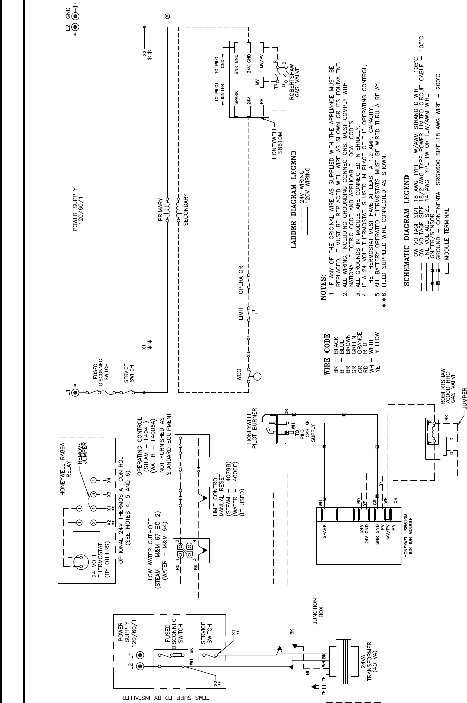
47
FIG. 40
SCHEMATIC WIRING DIAGRAM - EI CONTROL SYSTEM (ROBERTSHAW7000 GAS VALVE)
U.S.A. 5006B THRU 5009B
SECTION IV - OPERATION (continued)
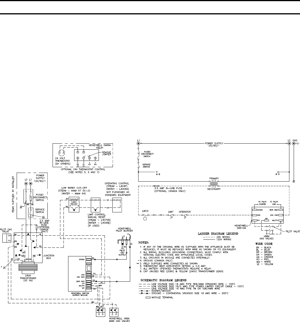
48
FIG. 41
SCHEMATIC WIRING DIAGRAM - EI CONTROL SYSTEM (V88 GAS TRAIN)
U.S.A. 5010B THRU 5014B
CANADA 5006B THRU 5014B
EI SEQUENCE OF OPERATION - 5006B THRU 5009B
WHEN OPERATING CONTROL CLOSES, THE ELECTRIC SPARK AND PILOT VALVE ARE AUTOMATICALLY
ENERGIZED. THE SENSING PROBE PROVES THE PRESENCE OF THE PILOT FLAME. INTERNAL SWITCH
ACTION DE-ENERGIZES THE SPARK AND ENERGIZES THE MAIN GAS VALVES STARTING MAIN BURNER
OPERATION. WHEN THE OPERATING CONTROL IS SATISFIED THE PILOT GAS VALVE AND THE MAIN GAS
VALVES ARE DE-ENERGIZED STOPPING THE BURNER OPERATION.
IN THE EVENT OF EXCESSIVE STEAM PRESSURE (STEAM BOILER) OR EXCESSIVE BOILER WATER
TEMPERATURE (WATER BOILER), THE HIGH LIMIT CONTROL WILL DE-ENERGIZE THE PILOT GAS VALVE
AND THE MAIN GAS VALVES STOPPING BURNER OPERATION.
THE LOW WATER CUT-OFF WILL ALSO STOP BURNER OPERATION IF THE WATER LEVEL IN THE BOILER
SHOULD DROP BELOW THE LOWEST SAFE LEVEL.
SECTION IV - OPERATION (continued)
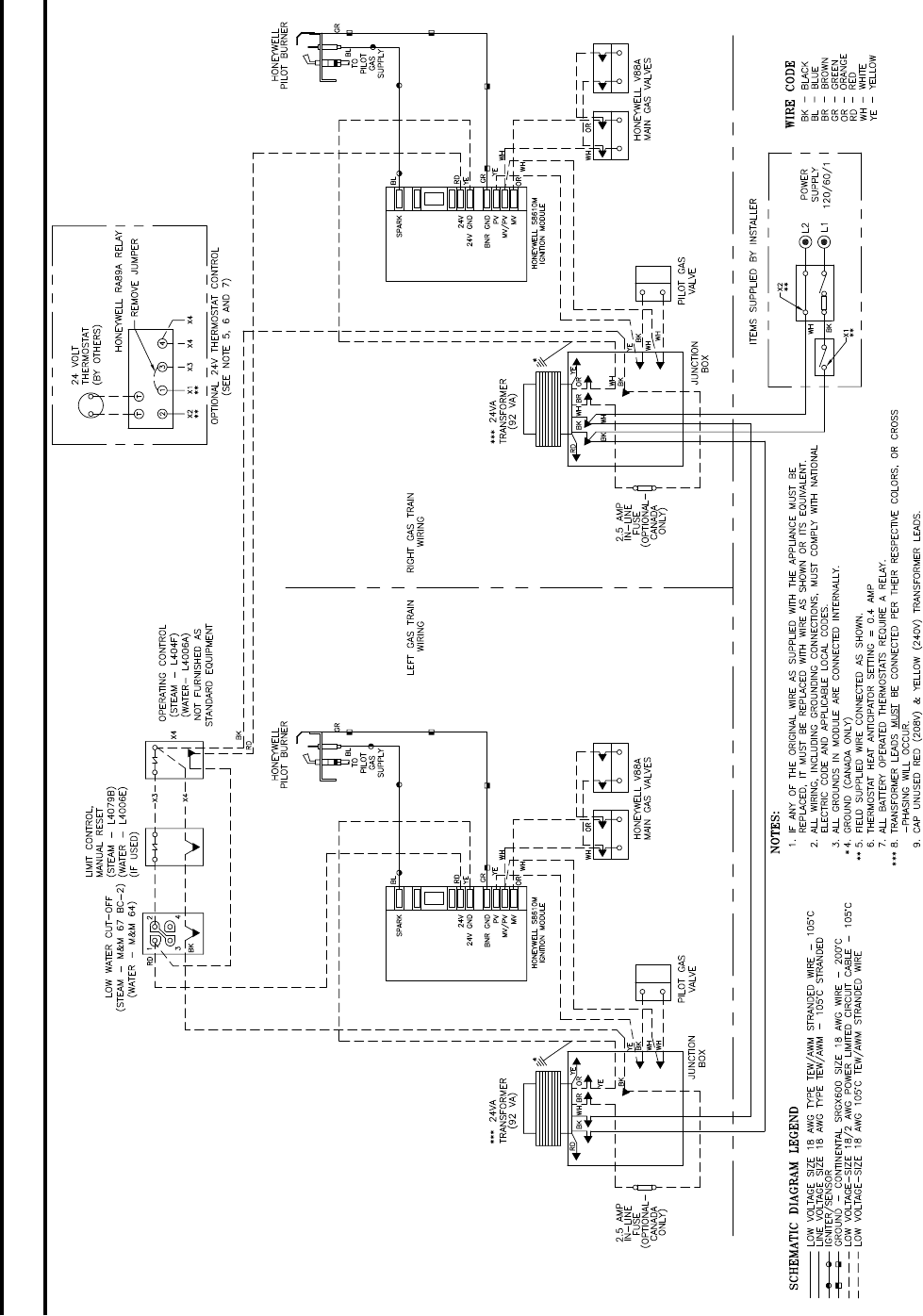
49
FIG. 42
SCHEMATIC WIRING DIAGRAM - 5015B THRU 5026B SECTION BOILERS
EI CONTROL SYSTEM
SECTION IV - OPERATION (continued)
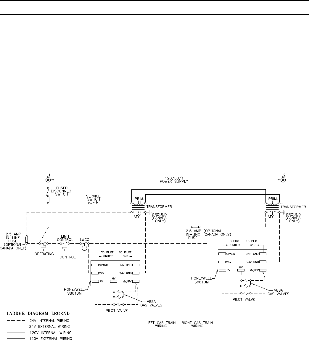
50
EI SEQUENCE OF OPERATION - 5010B THRU 5014B
WHEN OPERATING CONTROL CLOSES, THE ELECTRIC SPARK AND PILOT VALVE ON EACH SIDE ARE
AUTOMATICALLY ENERGIZED. THE SENSING PROBE ON EACH OF THE PILOTS PROVES THE PRESENCE
OF THE PILOT FLAME. INTERNAL SWITCH ACTION IN EACH IGNITION MODULE DE-ENERGIZES THE SPARK
AND ENERGIZES THE MAIN GAS VALVES FOR ITS RESPECTIVE GAS TRAIN, STARTING MAIN BURNER
OPERATION. WHEN THE OPERATING CONTROL IS SATISFIED THE PILOT GAS VALVE AND MAIN GAS
VALVES FOR EACH GAS TRAIN ARE DE-ENERGIZED STOPPING BURNER OPERATION.
IN THE EVENT OF EXCESSIVE STEAM PRESSURE (STEAM BOILER) OR EXCESSIVE WATER TEMPERATURE
(WATER BOILER) THE HIGH LIMIT CONTROL WILL DE-ENERGIZE THE PILOT VALVES AND MAIN GAS VALVES
ON BOTH SIDES STOPPING BURNER OPERATION.
THE LOW WATER CUT-OFF WILL ALSO STOP BURNER OPERATION IF THE WATER LEVEL IN THE BOILER
SHOULD DROP BELOW THE LOWEST SAFE LEVEL.
SHOULD ONE OF THE PILOT FLAMES FAIL TO IGNITE OR BECOME EXTINGUISHED, THE MAIN GAS VALVES
CONTROLLED BY THAT PARTICULAR PILOT WOULD CLOSE STOPPING BURNER OPERATION ON THE
BURNERS SUPPLIED BY THAT GAS TRAIN. OPERATION OF THE BURNERS SUPPLIED BY THE SECOND GAS
TRAIN WOULD BE UNAFFECTED.
FIG. 43
LADDER WIRING DIAGRAM - 5015B THRU 5026B SECTION BOILERS
EI CONTROL SYSTEM
SECTION IV - OPERATION (continued)
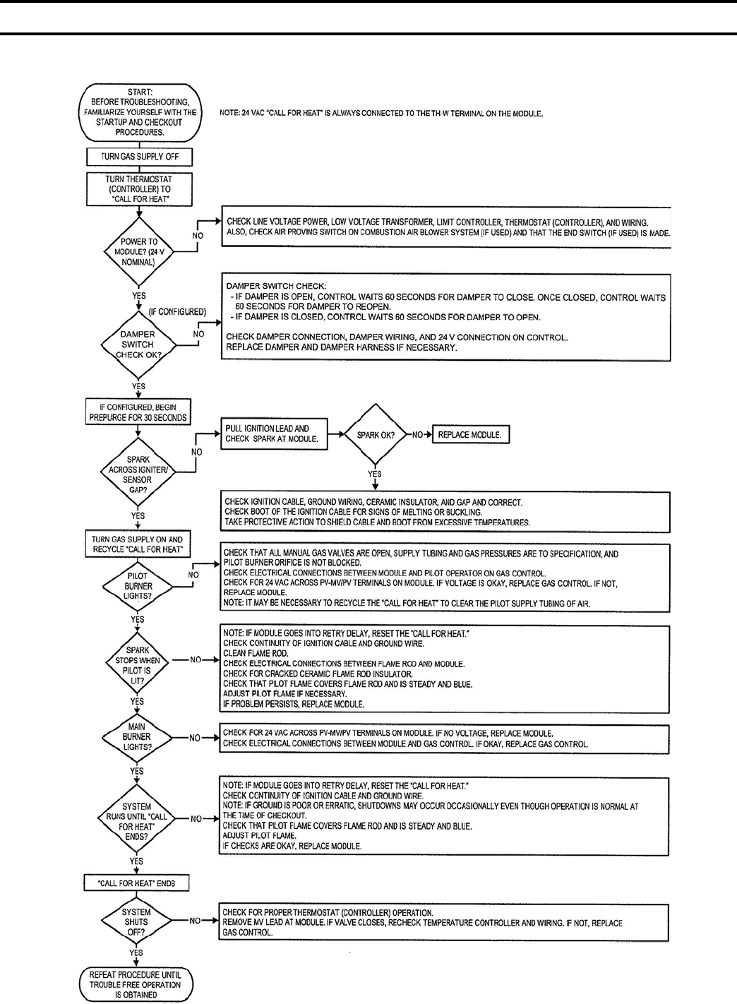
51
TROUBLE SHOOTING GUIDE
BOILERS EQUIPPED WITH S8610M INTERMITTENT ELECTRIC IGNITION
SECTION IV - OPERATION (continued)

52
SECTION IV - OPERATION (continued)
7. EP CONTROL SYSTEM – 5006B thru 5014B
The EP Control System utilizes an RM7890A Relay
Module and a Q179C Rectication Pilot, which in
addition to a pilot burner and rectifying ame rod ame
detector to prove pilot, includes an ignition electrode
for spark ignition of the pilot. A Webster 612-6A7
Transformer supplies the high voltage spark potential.
Once pilot ame continues as long as there is a “call for
heat” (intermittent electrically ignited pilot).
The RM7890A Relay Module Primary Control is a
non-programming amplifying relay which when used
with the Q179C Pilot provides solid state electronic
Flame Safeguard Protection that will not allow the main
gas valves to open on “call for heat” for that will shut
down main burners within 0.8 second if pilot ame is
not “proved”. Relay Module will lockout on safety
shutdown within 15 seconds if there is a pilot ame
failure on start or, if during the “run” cycle, pilot ame
is not re-established. Since #8 terminal in the Relay
Module is de-energized at end of safety switch timing, a
solenoid valve in the pilot line will close and thus 100%
shut-off is achieved.
a. OPERATING INSTRUCTIONS
(1) Make sure Manual Main Shut-off Valve and
all Pilot Valves have been off for at least ve
minutes.
(2) Set Operating and Limit Controls to desired
settings.
(3) Turn Manual Main Shut-off Valve and Pilot
Valve to Open Position.
(4) Turn on Main Electric Switch and Service
Switch – Pilot will automatically light main
burners.
SEQUENCE OF OPERATION EP - See Fig. 44
b. NORMAL OPERATION - 5006B thru 5014B
(1) When the operating control calls for heat,
terminal #6 of RM7890A Relay is energized.
(2) A component check circuit in the RM7890A
Relay is activated which, checks the electronic
network in the relay.
(3) Terminals #8 and #10 of the relay are energized.
Terminal #8 opens pilot line solenoid valve
supplying gas to pilot. Terminal #10 energizes
ignition transformer creating electric spark
ignition at pilot.
(4) Flame rod circuit between Q179C pilot and
RM7890A proves presence of pilot ame
electronically.
(5) Terminal #10 to ignition transformer is de-
energized.
(6) Terminal #9 is energized and supplies power to
the main gas valves.
(7) Main gas valves open and main burners are
lighted by pilot.
(8) When operating control is satised, terminals
#6 and #9 are de-energized. Main Gas Valves
and pilot line solenoid valve are all de-energized
and main burner and pilot burner ames are
extinguished.
c. SAFETY SHUTDOWN
(1) SAFETY SWITCH CIRCUIT
If limit control, low water cut-off or any other
electrical safety switch opens, power to terminal
#6 in relay is interrupted thus de-energized
terminal #9 and #8 in relay which de-energizes
main gas valves and pilot valves. Main gas
burners and pilot burners are immediately
extinguished. Normal operation can be resumed
when the cause of safety switch malfunction
is corrected. Make sure all manual resets are
activated where involved.
(2) PILOT FAILURE
(a) Pilot failure can occur during the start of
operating cycle of the boiler. Any pilot
failure, on the Q179C electronic pilot, after
ignition of pilot ame will close the main
gas valves in 0.8 second.
(b) For 15 seconds after failure of the Q179C
pilot, the relay through terminals #8 and #10
will try to establish pilot ame. If not pilot
ame can be sensed by the ame rod circuit,
terminal #8 and #10 are de-energized, and
the relay will lock out on safety.
(c) Pilot failure is caused by the following:
(1) Complete loss of gas supply.
(2) Poor ignition spark caused by low
voltage, poor ground connection, faulty
wiring, and possibly a defective ignition
transformer.
(3) Low gas pressure will prevent ame rod
circuit from sensing pilot ame properly.
(4) Unusually strong secondary air drafts
can blow the pilot ame away from the
ame rod momentarily causing nuisance
shutdown.
(5) A pilot line solenoid valve will not open
because of faulty wiring, low voltage, or
possibly the valve is defective.
(6) A defective RM7890A may be the cause
but items (1) thru (5) should be followed
rst. Refer also to RM7890A relay
literature furnished with the control.
(d) By referring to the Sequence of Operations
step-by-step operation of the system can
be controlled and the cause of pilot failure

53
can be readily found. After the cause of
the pilot failure has been corrected, resume
normal operation by following the Lighting
Instructions.
(3) SHUTDOWN INSTRUCTIONS
(a) Close manual shut-off valves and pilot
valves.
(b) Turn off main electric switch.
8. EP CONTROL SYSTEM – 5015B thru 5026B (see Fig.
45)
The 5015B thru 5026B boilers utilize two EP control
systems that are interconnected electrically thru all
operating and safety controls. Should any of the
aforementioned controls break the power supply circuit,
both EP control systems would be de-energized. The
succeeding paragraphs describe the function and
operation of each EP Control System. Should a pilot
failure on one EP Control System occur, the other EP
Control System would not be affected. Thus main
burners on the unaffected side would ignite on a “call
for heat” and would continue to operate until the
SECTION IV - OPERATION (continued)
operating control was satised.
The EP Control System utilizes and RM7890A Relay
Module and a Q179C Rectication Pilot, which in
addition to a pilot burner and rectifying ame rod ame
detector to prove pilot, includes an ignition electrode
for spark ignition of the pilot. A Webster 612-6A7
Transformer supplies the high voltage spark potential.
Once pilot ame is proven, ignition stops but pilot
ame continues as long as there is a “call for heat”
(intermittent electrically ignited pilot).
The RM7890A Primary Control is a non-programming
amplifying relay which when used with the Q179C
Pilot provides solid state electronic Flame Safeguard
Protection that will not allow the main gas valve to
open on “call for heat” or that will shut down main
burners within 0.8 second if pilot ame is not “proved”.
Relay Module will lock out on safety shutdown within
15 seconds if there is a pilot ame failure on start or, if
during the “run” cycle, pilot ame is not re-established.
Since #8 terminal in the Relay Module is de-energized
at end of safety switch timing, a solenoid valve in the
pilot line will close and thus 100% shut-off is achieved.
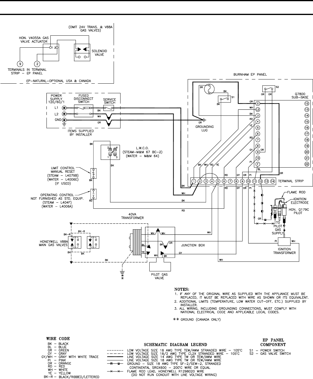
54
FIG. 44
WIRING DIAGRAM - 5006B THRU 5014B SECTION BOILERS
EP CONTROL SYSTEM
SECTION IV - OPERATION (continued)
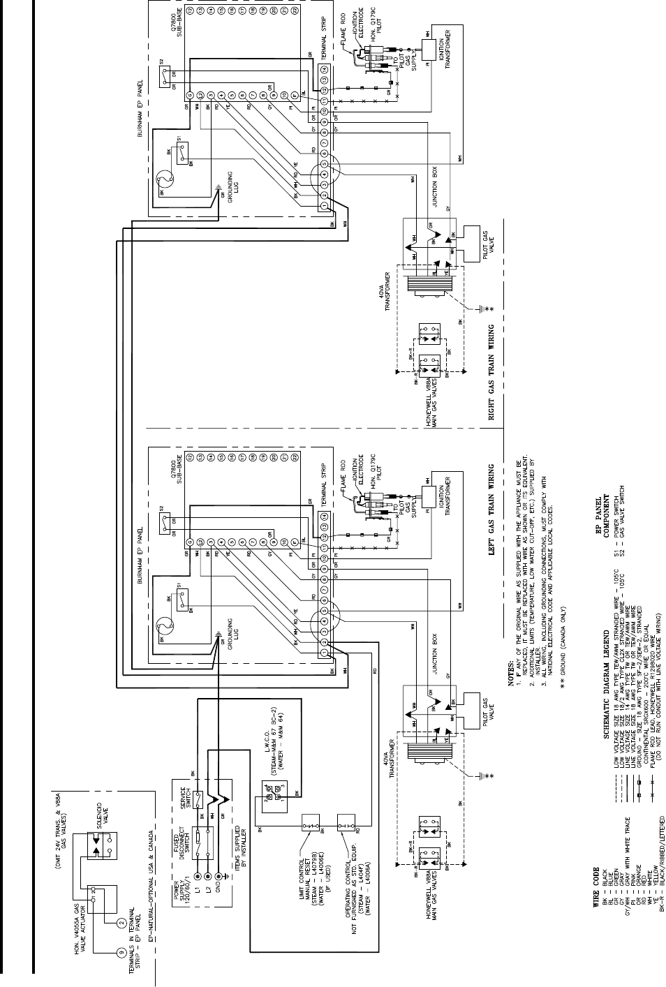
55
FIG. 45
WIRING DIAGRAM - 5015B THRU 5026B SECTION BOILERS
EP CONTROL SYSTEM
SECTION IV - OPERATION (continued)

56
a. OPERATING INSTRUCTIONS
(1) Make sure all Manual Main Shut-off Valves and
all Pilot Valves have been off for at least ve
minutes.
(2) Set Operating and Limit Controls to desired
setting.
(3) Turn all Manual Main Shut-off Valves and Pilot
Valves to Open Position.
(4) Turn on Main Electric Switch and Service
Switch. Pilots will automatically light main
burners.
SEQUENCE OF OPERATION EP – See Fig. 45
b. NORMAL OPERATION – 5015B thru 5026B
1. When the operating control calls for heat,
terminal #6 of each RM7890A is energized.
2. A component check circuit in each RM7890A is
activated which checks the electronic network of
the relay.
3. Terminals #8 and #10 of each RM7890A relay
are energized. Terminal #8 opens the pilot line
solenoid valve supplying gas to the Q179C pilot.
Terminal #10 energizes ignition transformer
creating electric spark ignition at the Q179C
pilot.
4. Flame rod circuit between each Q179C pilot and
terminal “11” on its respective RM7890A proves
presence of ame electronically at its Q179C
pilot.
5. Terminal #10 of each RM7890A and the ignition
transformer connected to it is de-energized.
6. Terminal #9 on each RM7890A is energized
supplying power to its respective main gas
valves.
7. Main gas valves open and main burners are
ignited by the pilot ames.
8. When the operating control is satised, terminals
6 and all other terminals on both RM7890A
relays are de-energized. The main gas valves
and pilot valve for each gas train are closed
and main burners and pilot burner ames are
extinguished.
c. SAFETY SHUTDOWN
(1) SAFETY SWITCH CIRCUIT
If limit control, low water cut-off or any other
electrical safety switch opens, power to terminal
6 and all other terminals on both RM7890A
relays are interrupted de-energizing the main
gas valves and pilot valves and the main gas
burners and pilot burners are immediately
extinguished. Normal operation can be resumed
when the cause of the safety switch malfunction
is corrected. Make sure all manual resets are
activated where applicable.
(2) PILOT FAILURE
(a) Pilot failure can occur during the start and
operating cycle of the boiler. Any pilot
failure on either of the Q179C Electronic
Pilots, after ignition of pilot ame will close
the pilot valve and the main gas valves
controlled by that particular RM7890A relay
in 0.8 second. The burners controlled by the
other RM7890A will continue to burn.
(b) For 15 seconds after failure of a Q179C
pilot, the relay through terminals #8 and #10
will attempt to re-establish pilot ame. If no
pilot ame can be sensed by the ame rod
circuit in 15 seconds, terminals #8 and #10
are de-energized, and the relay will lock out
on safety.
(c) Pilot failure is caused by the following:
(1) Complete loss of gas supply.
(2) Poor ignition spark caused by low
voltage, poor ground connection, faulty
wiring, and possibly a defective ignition
transformer.
(3) Low gas pressure will prevent ame rod
circuit from sensing pilot ame properly.
(4) Unusually strong secondary air drafts
can blow the pilot ame away from the
ame rod momentarily causing nuisance
shutdown.
(5) A pilot line solenoid valve will not open
because of faulty wiring, low voltage, or
possibly the valve is defective.
(6) A defective RM7890A may be the cause
but items (1) thru (5) should be followed
rst. Refer also to RM7890A relay
literature furnished with the control.
(d) By referring to the Sequence of Operations
step by step operation of the system can
be controlled and the cause of pilot failure
can be readily found. After the cause of
pilot failure has been corrected, resume
normal operation by following the Lighting
Instructions.
(3) SHUTDOWN INSTRUCTIONS
(a) Close manual shut-off valves and pilot
valves.
(b) Turn off main electric switch.
SECTION IV - OPERATION (continued)

57
9. THERMOCOUPLE CONTROL SYSTEM (Canada
Only)
The 5006B thru 5014B boilers are equipped with
a Thermocouple Control System that utilizes a
constant-burning Q327A pilot, a Q309 thermocouple,
and a L62GB-3C Pilot Safety Switch. The Q309
thermocouple proves pilot ame and, in the absence
of such, will cool and, within 45 to 90 seconds, will
cause the L62GB-3C Pilot Safety Switch to which it is
connected, to break the electrical circuit to the main gas
valves as well as shut off the ow of gas to the pilot.
Thus, 100% shut-off is achieved.
The 5015B thru 5024B boilers utilize two
Thermocouple Control Systems that are interconnected
electrically thru all operating and safety controls.
Should any of the aforementioned controls break the
power supply circuit, both Thermocouple Control
Systems would be de-energized. The proceeding
paragraph describes the function and operation of each
Thermocouple Control System. Should a pilot failure
on one Thermocouple Control System occur, the other
Thermocouple Control System would not be affected.
Thus main burners on the unaffected side would ignite
on a “call for heat” and would continue to operate until
the operating control was satised.
SECTION IV - OPERATION (continued)
a. LIGHTING INSTRUCTIONS
(1) Make sure that all main manual and pilot valves
have been off for at least ve (5) minutes.
(2) Set operating and limit controls to desired
setting.
(3) Open pilot valve.
(4) Depress button on pilot safety switch to which
it is connected and hold lighted match on pilot.
Hold button in for at least one minute, or until
the pilot burner remains lit after the button is
released. Repeat for second pilot when boiler is
so equipped.
(5) Open manual main shut-off valve(s).
(6) Turn on main electric switch.
NORMAL OPERATION SEQUENCE
5006B thru 5014B, see Fig. 46
5015B thru 5024B, see Fig. 47
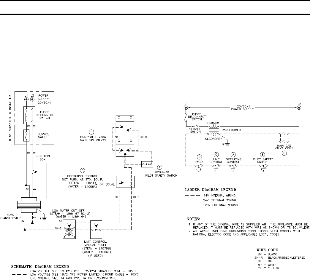
58
When operating control (A) calls for heat, it energizes main gas valves (B), starting burner operation.
The burners will operate until operating control (A) is satised. The high limit control (C), will stop burner
operation in case of excessive steam pressure (steam boiler) or excessive boiler water temperature (water boiler).
Low water cut-off (D) will stop burner operation if the water level in boiler drops below the lowest safe level.
The pilot safety switch (E), connected to main gas valve (B), prevents operation of the main burners in case the
pilot ame becomes extinguished. Pilot safety switch (E) provide for 100% shut-off of gas supply.
FIG. 46
WIRING DIAGRAM - 5006B THRU 5014B SECT. BOILERS
THERMOCOUPLE CONTROL SYSTEM
CANADA ONLY
SECTION IV - OPERATION (continued)

59
When the operating control (A) calls for heat, it energizes the main gas valves (B) in both gas trains
starting burner operation. The burners will operate until the operating control is satised. The high limit
control (C) will stop burner operation in case of excessive steam pressure (steam boiler) or excessive
boiler water temperature (water boiler).
The low water cut-off (D) will stop burner operation if the water level in the boiler drops below the low-
est safe level.
Should one of the pilot ames become extinguished the pilot safety switch (E) to which it is connected
would shut off the gas supply to that pilot and to the main gas valves and burners it is serving (100%
shut-off). Operation of the burners supplied by the second gas train will be unaffected.
FIG. 47
WIRING DIAGRAM - 5015B THRU 5024B SECTION BOILERS
THERMOCOUPLE CONTROL SYSTEM
CANADA ONLY
SECTION IV - OPERATION (continued)

60
10. CHECK GAS INPUT RATE TO BOILER
(1) Input Rate and Maximum Inlet Pressure shown on
Rating Plate must not be exceeded. Inlet pressure
must not be lower than minimum inlet pressure
shown on Rating Plate.
(2) All Rate checks and all adjustments are to be
made while boiler is ring – all other appliances
connected to the same meter as the boiler must be
off.
(3) Water Manometer or water column gauge should
be connected to a shut-off valve installed in the
1/8” pipe tapping in each manifold – boiler off. By
installing gas valve upstream of manometer, gas
pressure can be introduced gradually – without
shut-off valve, surge of pressure when boiler is
turned on, could blow liquid out of manometer.
(4) LP Gas Input
(a) Adjust Gas Train Regulator(s) so that manifold
pressure is ten (10) inches water column.
Turning Regulator Adjusting Screw Clockwise
increases pressure, Counterclockwise rotation
decreases pressure. If boiler is equipped with
two manifolds (5015B thru 5026B), pressure
in each must be equal.
(5) Natural Gas Input
(a) Approximate Input – Adjust Gas Train
Regulator(s) so that manifold pressure is three
and a half (3½) inches from water column.
Turning Regulator Adjusting Screw Clockwise
increases pressure, Counterclockwise rotation
decreases pressure. If boiler is equipped with
two manifolds, pressure in each must be equal.
If more accurate check on input is necessary,
see (b) below.
For minor input changes readjust Gas Train
Regulator(s) to increase or decrease manifold
pressure to obtain corresponding increase or
decrease in gas input. If it is necessary to
increase manifold pressure more than 0.3” of
water to obtain rated input, remove orices
and drill one size larger. Reinstall and recheck
input rate.
(b) Additional Check on Input – Since input is
a function of heating value, specic gravity
and volume of gas ow contact your utility
for the rst two items in order to utilize the
formula below. The gas meter should then be
clocked for three (3) minutes with stop watch
and substituting the appropriate values in the
formula below, determine what the gas ow
should be in this 3 minute period to give the
input shown on the Rating Plate:
(c) ADJUST AIR SHUTTERS – See Section V; 5.
Burners are normally shipped with the air
shutters in the wide open position. Loosen air
shutter securing screws and close air shutters
until yellow tips appear on ames, then open
shutters slowly until dened inner cones may
be seen. Lock shutters in this position.
(d) ADJUST BLEED LINE REGULATOR
(V88A’s)
All gas boilers for the USA and Canada are
normally equipped with two diaphragm gas
valves per manifold. The gas valve(s) nearest
the manifold on all boilers, is equipped with an
adjustable bleed. This bleed regulator should
be adjusted so that the burners reach full re
in approximately 10-12 seconds after the main
gas valves have been energized.
(e) ADJUST PILOT LINE PRESSURE – See
Section V - Service; 6. Pilot Flame
Shut down boiler and remove gas valve and
manometer from 1/8” pipe tapping in each
manifold. Plug tappings with square head pipe
plugs. Install gas valve in tee in each pilot line.
Connect manometer to each gas valve and, with
boiler in operation, set pilot line pressure at
5.5” water – natural gas boilers and 6.5” water
– propane gas boilers.
Shut boiler down, remove gas valves and
manometers and plug tees with square head
pipe plugs. Restart boiler.
cu. ft. per =
3 min.
Btuh Input
Heating x 20 x multiplier
Value
of gas
(from
table
below)
(Btu/cu.ft.)
spec. gravity multiplier
.50 1.10
.55 1.04
.60 1.00
.65 0.96
.70 0.93
SECTION IV - OPERATION (continued)
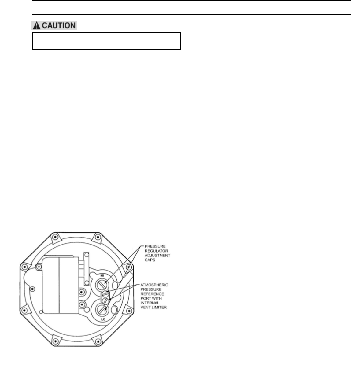
61
The following procedures should only be
performed by a qualied service technician.
11. MINIMUM INPUT ADJUSTMENTS
This section covers Minimum Input Adjustments on
Honeywell V8944B Diaphragm Type “Lo-Hi-Lo” Gas
Valves, Honeywell V5055B Fluid Power Gas Valves
equipped with either a V4062A “Lo-Hi-Lo” Actuator or
a V9055A “Modulating” Actuator.
a. Minimum Input Adjustments – “Lo-Hi-Lo”
Combination Valve, V8944B (Natural Gas Only)
On boilers equipped with the V8944B combination
diaphragm valve/regulator, Low Fire Adjustment
should not be less than Minimum Input shown on
Rating Plate (1/3 of full rated input). Fig. 48 shows
the outlet pressure adjustment screws for low and
high re. The V8944B low and high re pressure
settings are factory set at 0.8” and 3.5” W.C.
respectively. If further adjustments are necessary,
remove pressure regulator adjustment caps and
insert a screwdriver to raise or lower the regulator
pressure.
c. MINIMUM INPUT ADJUSTMENTS –
MOTORIZED “MODULATING” ACTUATOR,
V9055A
On boilers equipped with Fluid Power Valves that
have “Modulating” Actuators, Low Fire Adjustment
should not be less than Minimum Input shown on
Rating Plate (1/3 of full rated input).
Fig. 50 shows the Low Fire Adjusting Screw for
increasing or decreasing low re input on the
Honeywell V9055A “Modulating” Actuator. To
adjust the low re setting after the burners are “on”,
the following procedure should be used.
(1) With power to actuator “off”, remove the wiring
compartment cover.
(2) Check to make sure the low re adjustment is
set at MAX (full clockwise) to insure a safe
light-off. (Low re adjustment is preset at the
factory in the MAX position.)
Fig. 49 shows the Limit Switch Cam and Scales to
indicate direction to rotate cam for increasing or
decreasing low re input on the Honeywell V4062A
“Lo-Hi-Lo” Actuator. To adjust the low re setting
after the burners are “on”, the following procedure
should be used.
(1) With power to actuator “off”, remove the
wiring compartment cover.
(2) Check to be sure the low re adjustment is set
at MAX to insure a safe light-off. (Low re
adjustment is preset at factory in the MAX
position.)
(3) Disconnect the controller lead from terminal #4
on the actuator to keep the valve in the low re
position.
(4) Start the system and establish the main burner
ame.
(5) Loosen the setscrew in the cam (Fig. 49) with
the special wrench taped to inside of actuator
cover. Keep the wrench seated in the setscrew.
Rotate the cam slightly downward (by moving
the wrench toward the base of actuator) to open
bleed valve. Actuator will start to close.
(6) When valve reaches desired low re position,
quickly tighten setscrew and remove wrench. If
the desire low re setting is “missed”, merely
loosen the setscrew and rotate cam in the
opposite direction to the desired set point.
(7) Shut down burner, and then restart. Repeat
several times to be sure the low re setting
is that desired and suitable for correct burner
lightoff. Readjust if necessary.
(8) Disconnect power and reconnect controller lead
removed in step (3) above.
(9) Replace the wiring compartment cover.
b. MINIMUM INPUT ADJUSTMENTS –
“Lo-Hi-Lo” MOTORIZED ACTUATOR, V4062A
On boilers equipped with Fluid Power Valves that
have “Lo-Hi-Lo” Actuator, Low Fire Adjustment
should not be less than Minimum Input shown on
Rating Plate (1/3 of full rated input).
SECTION IV - OPERATION (continued)
FIG. 48
V8944B COMBINATION VALVE
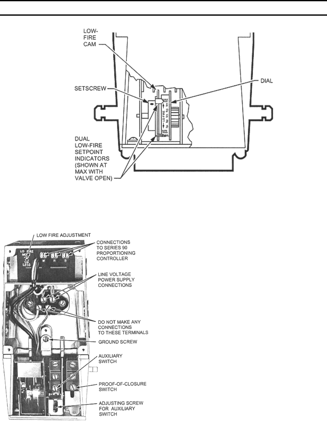
62
FIG. 49
LOW FIRE ADJUSTMENT - V4062 ACTUATOR
(3) Remove the lead to V9055A terminal R.
Jumper terminal R to W. This will prevent the
actuator from going to the high re position.
(4) Energize the system and light the main burner.
(5) Use a Phillips screwdriver, or standard type with
a blade no more than 3/16 inch wide, to turn
the low re adjusting screw for the desired low
re position. DO NOT PUSH INWARD ON
SCREW.
(6) Shut down the burner, and then restart. Repeat
several times to be sure the low re setting is
that desired and suitable for correct burner light
off.
(7) Turn off power supply. Remove R-W jumper,
and reconnect the lead to terminal R on the
V9055A.
(8) Replace the wiring compartment cover.
FIG. 50
LOW FIRE ADJUSTMENT - V9055A ACTUATOR
12. MAIN BURNER FLAMES should have a clearly
dened inner cone, see Fig. 55 with no yellow tipping.
Orange-yellow streak caused by dust should not be
confused with true yellow tipping.
13. CHECK PILOT FLAME. Flame should be a blue
medium hard ame enveloping approximately 3/8” of
the end of the thermocouple, ame sensor, or sensing
probe, see Fig. 56 thru 59.
SECTION IV - OPERATION (continued)
63
14. CHECK THERMOSTAT OPERATION. Raise and
lower thermostat setting as required to start and stop
burners.
15. CHECK HIGH LIMIT CONTROL. Jumper
Thermostat terminals or thermostat connections in
Limit Control. Allow burners to operate until shutdown
by limit. REMOVE JUMPER.
16. TEST IGNITION SYSTEM SAFETY SHUT-OFF
DEVICE AS FOLLOWS:
Place the boiler into operation by following the
appropriate lighting instructions in this manual.
Proceed with test as follows:
a. Thermocouple Pilot System
Using a 3/8” wrench loosen the thermocouple lead
at the gas valve. Main gas and pilot gas must shut
off. If not, replace gas valve.
b. EI Pilot System
Carefully remove ignitor sensor wire from ignition
module Main gas and pilot gas must shut off
immediately. If not, replace the module.
c. EP Pilot Systems
Carefully remove the ame rod wire from terminal
“11” on the RM7890 Control. Main gas and pilot
gas must shut off. If not, replace the RM7890
Control.
17. COMBUSTION CHAMBER BURN-OFF
a. The mineral wool combustion chamber panels
contain a cornstarch based binder that must be
burned out at installation to prevent odors during
subsequent boiler operation.
b. Ventilate the boiler room, set the high limit to its
maximum setting, set the thermostat to call for heat.
Allow the boiler to re for at least an hour or until
the odor from the cornstarch has dissipated.
c. Return the high limit and thermostat to their desired
settings.
Avoid operating this boiler in an environment
where saw dust, loose insulation bers, dry wall
dust, etc. are present. If boiler is operated under
these conditions, the burner interior and ports
must be cleaned and inspected daily to insure
proper operation.
SECTION IV - OPERATION (continued)
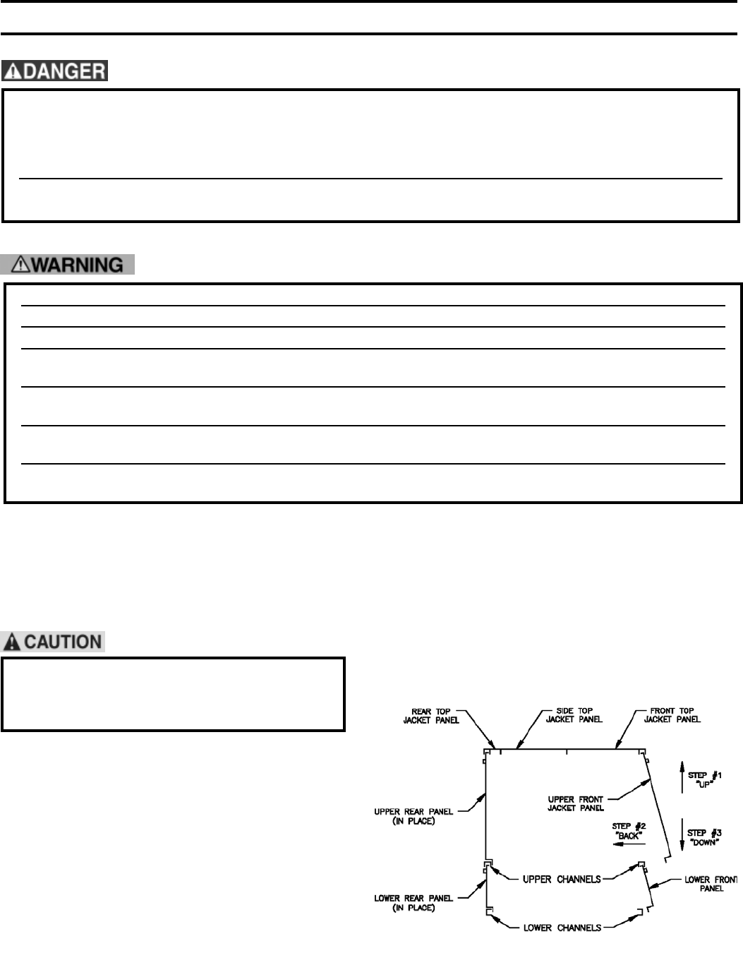
64
1. GENERAL – “Inspection should be conducted
annually. Service as frequently as specied in
paragraphs below.” While service or maintenance is
being done, Electrical Power and all Gas Supply to the
Boiler must be “off”.
Label all wires prior to disconnection when
servicing controls. Wiring errors can cause
improper and dangerous operation. Verify proper
operation after servicing.
2. VENT SYSTEM – Vent system should be checked
annually for:
a. obstructions
b. accumulations of soot
c. deterioration of vent pipe or vent accessories due to
condensation or other reasons
d. proper support – no sags, particularly in horizontal
runs
e. tightness of joints
Remove all accumulations of soot with wire brush
and vacuum. Remove all obstructions. Replace
all deteriorated parts and support properly. Seal all
joints. See Fig. 53.
SECTION V – SERVICE
3. CLEANING OF FLUES AND BURNERS – Flue
passageways in the boiler sections should be checked
annually for any blockage or accumulation of soot.
To obtain access to the ue cleanout panels, which
are installed on both the front and rear of the boiler,
the upper front and upper rear jacket panels must be
removed, see Fig. 51. Also remove front vestibule
panel. See Fig. 20.
FIG. 51
REMOVAL OF JACKET FRONT PANEL
This boiler used ammable gas, high voltage electricity, moving parts, and very hot water under high
pressure. Assure that all gas and electric power supplies are off and that the water temperature is cool
before attempting any disassembly or service.
More than one gas shut-off valve and electrical disconnect switch are used on the boiler. Assure that
all gas valves and electrical disconnect switches are off before attempting any disassembly or service.
Do not attempt any service work if gas is present in the air in the vicinity of the boiler.
Never modify, remove or tamper with any control device.
This boiler must only be serviced and repaired by skilled and experienced service technicians.
If any controls are replaced, they must be replaced with identical models.
Read, understand and follow all the instructions and warnings contained in all the sections of this manual.
If any electrical wires are disconnected during service, clearly label the wires and assure that the wires
are reconnected properly.
NEVER operate boiler without all sight glasses and brackets in place and securely fastened and sealed.
Very HOT combustion gas may cause burn injury.
Read, understand and follow all the instructions and warnings contained in ALL of the component
instruction manuals.
Assure that all safety and operating controls and components are operating properly before placing the
boiler back in service.
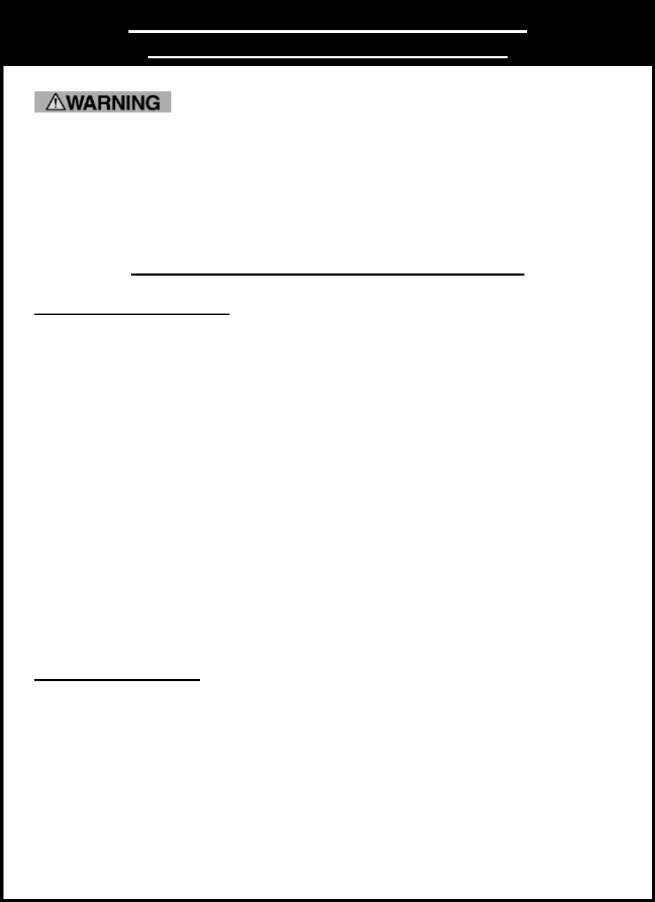
65
Important Product Safety Information
Refractory Ceramic Fiber Product
The Repair Parts list designates parts that contain refractory ceramic fibers
(RCF). RCF has been classified as a possible human carcinogen. When
exposed to temperatures above 1805°F, such as during direct flame contact,
RCF changes into crystalline silica, a known carcinogen. When disturbed as a
result of servicing or repair, these substances become airborne and, if inhaled,
may be hazardous to your health.
AVOID Breathing Fiber Particulates and Dust
Precautionary Measures:
Do not remove or replace RCF parts or attempt any service or repair work
involving RCF without wearing the following protective gear:
1. A National Institute for Occupational Safety and Health (NIOSH)
approved respirator
2. Long sleeved, loose fitting clothing
3. Gloves
4. Eye Protection
•Take steps to assure adequate ventilation.
•Wash all exposed body areas gently with soap and water after contact.
•Wash work clothes separately from other laundry and rinse washing
machine after use to avoid contaminating other clothes.
•Discard used RCF components by sealing in an airtight plastic bag. RCF
and crystalline silica are not classified as hazardous wastes in the United
States and Canada.
First Aid Procedures:
•If contact with eyes: Flush with water for at least 15 minutes. Seek
immediate medical attention if irritation persists.
•If contact with skin: Wash affected area gently with soap and water.
Seek immediate medical attention if irritation persists.
•If breathing difficulty develops: Leave the area and move to a location
with clean fresh air. Seek immediate medical attention if breathing
difficulties persist.
•Ingestion: Do not induce vomiting. Drink plenty of water. Seek
immediate medical attention.
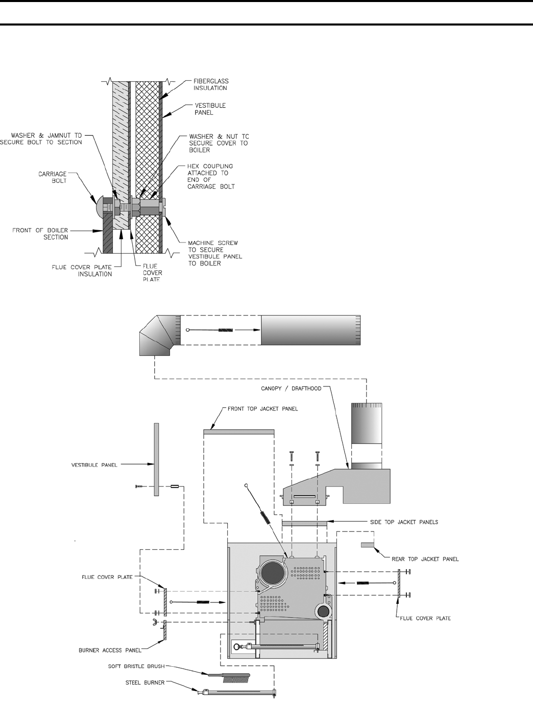
66
Remove the Front Cleanout Panels rst by removing
the upper and lower nuts and washers securing these
panels to the boiler sections, see Fig. 52.
CARE SHOULD BE EXERCISED IN REMOVING
THE CLEANOUT PLATES FROM THE BOLTS SO
THAT THE INSULATION IS NOT DAMAGED. IF
DAMAGED, ALL EDGES OF THE CLEANOUT
PLATES SHOULD BE SEALED WITH BOILER
PUTTY WHEN REINSTALLED UNTIL
INSULATION CAN BE REPLACED.
Using a ashlight, examine all ue passageways. If
passageways are free of soot and obstructions, it is not
necessary to remove the rear cleanout panels. Remove
the Burner Access Panels at front of base and place
paper or cardboard over burners. With long handle
wire ue brush and vacuum, brush ueways thoroughly
through front and rear cleanout openings – see Fig. 53.
Remove material placed over burners and vacuum the
following with care so as not to disturb base insulation:
oor, top of burners, primary air opening in burners,
and primary air openings in pilot. This will remove any
dust or lint that may have accumulated as well as any
foreign matter that may have been dislodged during the
cleaning of the ues.
FIG. 53
CLEANING OF FLUEWAYS
SECTION V – SERVICE (continued)
FIG. 52
ATTACHMENT OF FLUE COVERS
67
THIS PAGE LEFT BLANK INTENTIONALLY

68
SECTION V – SERVICE (continued)
FIG. 54-1
PILOT LOCATIONS
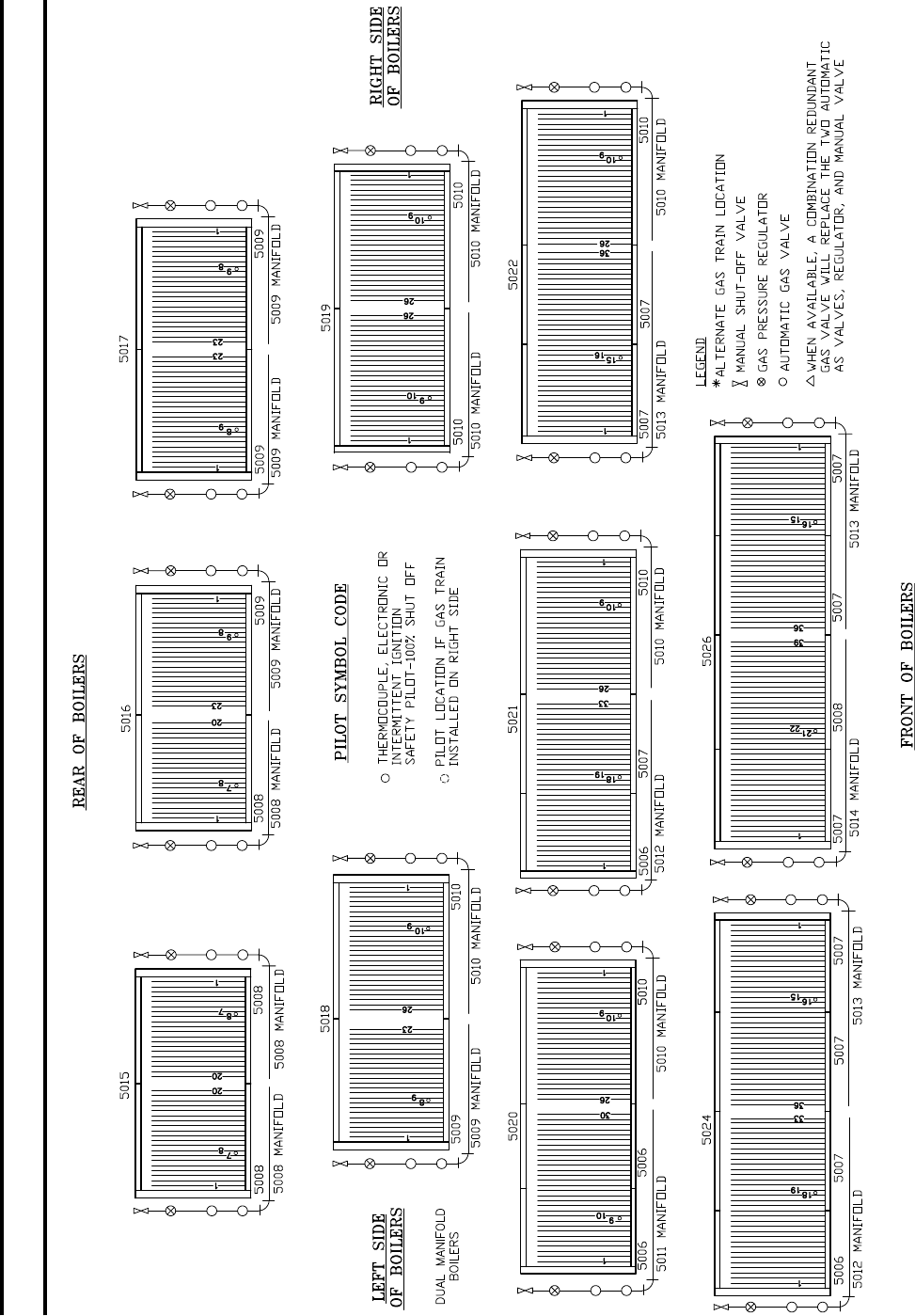
69
SECTION V – SERVICE (continued)
FIG. 54-2
PILOT LOCATIONS
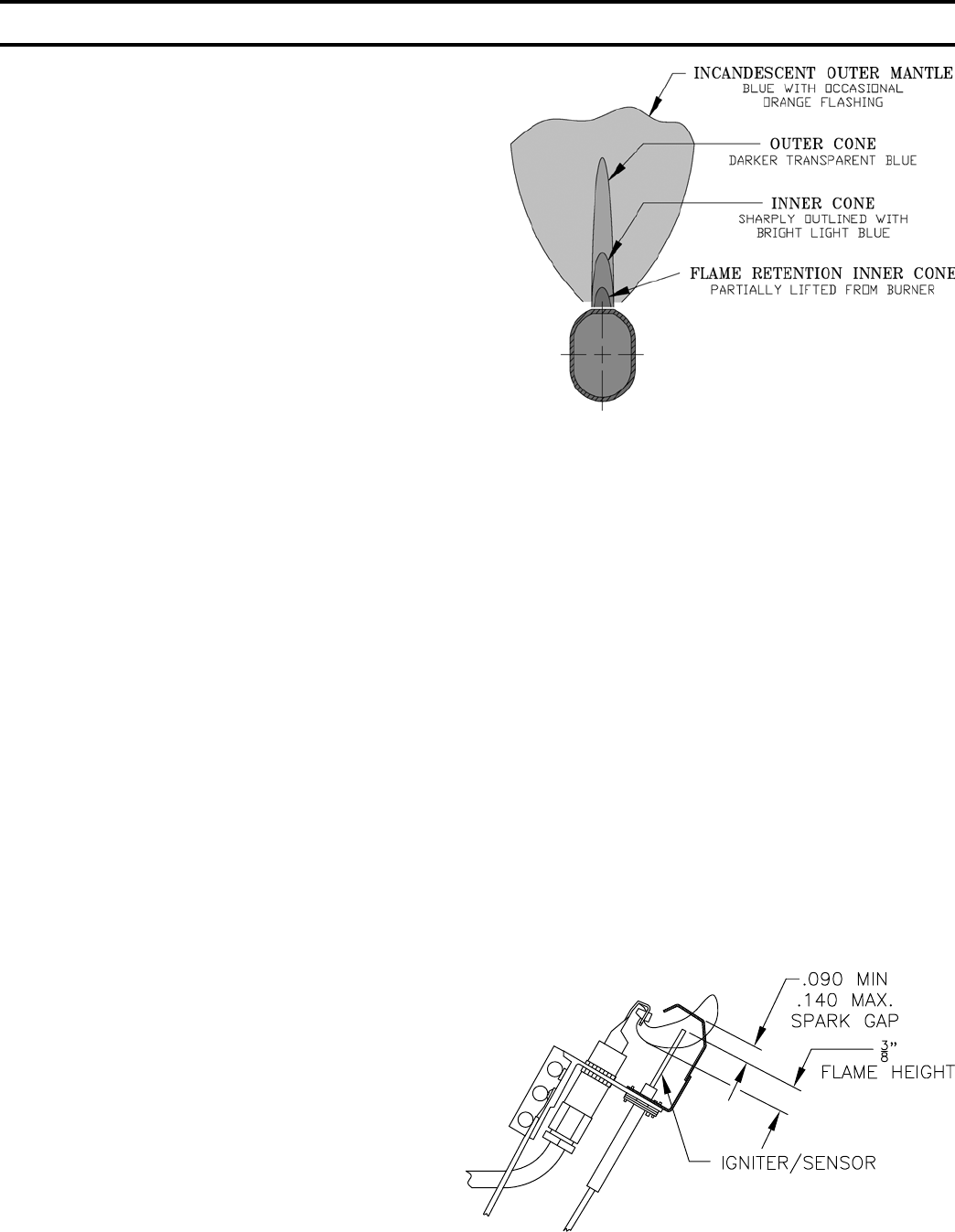
70
If Burners must be removed, use the following
procedure:
a. Mark location on manifold of all burners with pilots.
b. Using a pair of pliers, remove hitch pin clips
(shaped like a hairpin) from groove in main burner
orices. SAVE ALL CLIPS.
c. Remove all burners without pilots by lifting front
of burner slightly, then pushing burner toward rear
of boiler until front of burner clears orice, then
lift rear of burner until head of weld pin on bottom
rear of burner clears keyhole slot in base rear
panel. Burner is now free and can be lifted out thru
opening in base front frame.
d. Remove all burners with pilots by rst tracing all
electrical leads coming from pilot to their points of
connection, remove leads from terminals to which
they are connected, and then tag each lead with
respective terminal designation. Disconnect Pilot
Tubing at nearest connection to pilot and remove
burner as outlined in paragraph c. above.
e. When replacing burners, reverse procedure used in
removal of burners. Make sure burners are secure in
keyhole slots in base rear panel and hitch pin clips
are installed in grooves in all main burner orices.
Burners with pilots must be in same locations as
original installation. If markings placed on manifold
(when burners were removed) are obliterated, see
Fig. 54. Reconnect electrical leads and reconnect
pilot tubing.
Reinstall Flue Cleanout Plates so that they are gas
tight. Reinstall Burner Access Panels and Jacket
Panels.
4. LUBRICATION
Manufacturers Instruction should be followed on all
parts installed on the boiler that require lubrication.
Generally this involves only the circulator in a hot
water system. This includes:
(a) Type of lubricant to be used
(b) Frequency of lubrication
(c) Points to lubricate
5. MAIN BURNER FLAMES –
Main Burner Flames should be checked at initial
start-up, annually thereafter, or after ueway cleaning,
or after an extended shutdown period. Main Burner
Flame should have a clearly dened inner cone, see
Fig. 55, with no yellow tipping. Orange-yellow streaks
caused by dust should not be confused with true yellow
tipping.
Yellow-tipping indicates a lack of primary air and
normally can be corrected by opening the air shutter.
Improper alignment of burner on orice will also affect
primary air injection.
SECTION V – SERVICE (continued)
FIG. 55
MAIN BURNER FLAME ADJUSTMENT
FIG. 56
PILOT FLAME - HONEYWELL Q3481B
6. PILOT FLAME –
Pilot Flame should be checked at initial start-up,
annually thereafter, or after ueway cleaning, or after
an extended shutdown period.
The EI Control System utilizes a Honeywell Q3481B
pilot. Flame should be adjusted by means of the pilot
line regulator 5.5” WC pilot line press so that a medium
hard center ame envelopes approximately 3/8” of
the end of the sensing probe, see Fig. 56. If ame
is yellow, primary air slot may be covered with dirt
or lint. This can be removed with a soft brush or by
vacuuming.
a. To adjust or check spark gap between electrode and
hood on Honeywell Q3481B intermittent pilot. (See
Fig. 56)
1. Use a round wire gauge to check spark gap.
2. Spark gap should be 0.1” for optimum
performance.
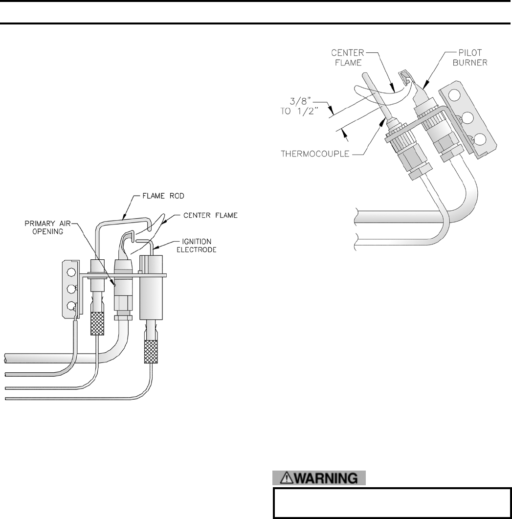
71
SECTION V – SERVICE (continued)
FIG. 57
PILOT FLAME
HONEYWELL Q179C PILOT
FIG. 58
PILOT FLAME
HONEYWELL Q327A PILOT W/THERMOCOUPLE
7. LOW WATER CUT-OFF –
a. Float Type Low Water Cut-off
During the heating season, if an external low water
cut-off is on the boiler, the blow off valve should
be opened once a month (use greater frequency
where conditions warrant), to ush out the sediment
chamber so the device will be free to function
properly.
Low-water fuel cut-offs and water feeders should
be dismantled annually by qualied personnel,
to the extent necessary to insure freedom from
obstructions and proper functioning of the
working parts. Inspect connecting lines to boiler
The EP Control Systems utilize a Honeywell Q179C
Flame Rectication Pilot. Adjust pilot line regulator
(5.5” WC in pilot line) so that a medium hard center
ame envelops ame rod, see Fig. 57. If ame is
yellow, primary air opening may be covered with dirt
or lint. This can be removed with a soft brush or by
vacuuming.
The Thermocouple Control System utilizes a
Honeywell Q327A non-primary aerated pilot with a
Q309A thermocouple. Adjust pilot line regulator to
give a steady ame enveloping 3/8” to 1/2” of the tip of
the thermocouple, see Fig. 58.
for accumulation of mud, scale, etc. and clean as
required. Examine all visible wiring for brittle or
warn insulation and make sure electrical contacts
are clean and that they function properly. Give
special attention to solder joints on bellows and oat
when this type of control is used. Check oat for
evidence of collapse and check mercury bulb (where
applicable) for mercury separation or discoloration.
Do not attempt to repair mechanisms in the eld.
Complete replacement mechanisms, including
necessary gaskets and installation instructions, are
available from the manufacturer.
Before returning boiler to service:
Follow this low water cut-off check out procedure:
- Set thermostat to the highest setting.
- While boiler is operating, open drain valve
and slowly drain down boiler water.
72
SECTION V – SERVICE (continued)
Do not drain water below gauge glass.
- Main burners should turn off when water
level drops below low water cut-off. At this
point the water level in gauge glass will just
be visible.
- Be sure that it is the low water cut-off
control and not the room thermostat,
pressure cut-out or other control that has
shut off the burners.
- Rell the boiler to the normal water level.
- Main burners should reignite.
- Clean out the boiler according to the
instructions for steam boilers on page 43.
- Reset controls for normal operation.
8. FREQUENT WATER ADDITION
A leaky system will increase the volume of make-up
water supplied to the boiler which can signicantly
shorten the life of the boiler. Entrained in make-up
water are dissolved minerals and oxygen. When the
fresh, cool make-up water is heated in the boiler the
minerals fall out as sediment and the oxygen escapes
as a gas. Both can result in reduced boiler life. The
accumulation of sediment can eventually isolate
the water from contacting the cast iron. When this
happens the cast iron in that area gets extremely hot
and eventually cracks. The presence of free oxygen
in the boiler creates a corrosive atmosphere which, if
the concentration becomes high enough, can corrode
the cast iron through from the inside. Since neither of
these failure types are the result of a casting defect the
warranty does not apply. Clearly it is in everyone’s best
interest to prevent this type of failure. The maintenance
of system integrity is the best method to achieve this.
Refer to Recommended Water Quality Requirements
chart on Page 44.
9. OXYGEN CORROSION:
Oxygen contamination of the boiler water will cause
corrosion of iron and steel boiler components, and
can lead to boiler failure. Burnham Commercial’s
standard warranty does not cover problems caused
by oxygen contamination of boiler water or scale
(lime) build-up caused by frequent addition of
water.
There are many possible causes of oxygen
contamination such as:
a. Addition of excessive make-up water as a result
of system leaks.
b. Absorption through open tanks and ttings.
c. Oxygen permeable materials in the distribution
system.
In order to ensure long product life, oxygen
sources should be eliminated. This can be
accomplished by taking the following measures:
a. Repairing system leaks to eliminate the need for
addition of make-up water.
b. Eliminating open tanks from the system.
c. Eliminating and/or repairing ttings which allow
oxygen absorption.
d. Use of non-permeable materials in the
distribution system.
e. Isolating the boiler from the system water by
installing a heat exchanger.
If, during normal operation, it is necessary to add water to this boiler more frequently than once a month,
consult a qualied service technician to check your system for leaks. A leaky system will increase the
volume of make-up water supplied to the boiler which can signicantly shorten a life of the boiler. Entrained
in make-up water are dissolved minerals and oxygen. When the fresh, cool make-up water is heated in the
boiler the minerals fall out as sediment and the oxygen escapes as a gas. Both can result in reduced boiler
life. The accumulation of sediment can eventually isolate the water from contacting the cast iron. When this
happens the cast iron in that area gets extremely hot and eventually cracks. The presence of free oxygen
in the boiler creates a corrosive atmosphere which, if the concentration becomes high enough, can corrode
the cast iron through from the inside. Since neither of these failure types are the result of a casting defect
the warranty does not apply. Clearly it is in everyone’s best interest to prevent this type of failure. The
maintenance of system integrity is the best method to achieve this.
73
,reliobnonoitamrofnignikeesnehW.rotcartnocgnitaehruoyllac,reliobotsriaperroecivresroF
.lebaLgnitaRnonwohssarebmuNlaireSdnarebmuNledoMrelioBedivorp
rebmuNledoMrelio
Br
ebmuNlaireSrelio
Be
taDnoitallatsnI
_________05
K_
______6
rotcartnoCgnitaeH rebmuNenohP
sserddA

74
REPAIR PARTS INDEX
ITEM PAGE NOS.
Base Parts ...................................................................................................................... 75 thru 78
Integral Draft Hoods & Sections ..................................................................................... 79 thru 80
Sections ...................................................................................................................................... 81
Base/Pilot Assemblies ................................................................................................................ 82
Jackets ........................................................................................................................... 83 thru 87
Water / Steam Trim ......................................................................................................... 88 and 89
Gas Trains ...................................................................................................................... 90 thru 96
Support Brackets, Ignition Modules .............................................................................. 97 thru 101
Pilotstats, Transformers, Pilot
Solenoid Valves & Pilot Line
Regulators
EP Control Panel ...................................................................................................................... 102
Pilot Assemblies ......................................................................................................... 103 and 104
All Series 5B Repair Parts may be obtained through your local Burnham Wholesale distributor.
Should you require assistance in locating a Burnham Distributor in your area, or have questions
regarding the availability of Burnham products or repair parts, please contact Burnham Customer
Service at: 888-791-3790 or Fax (717) 293-5803.
SECTION VI - REPAIR PARTS
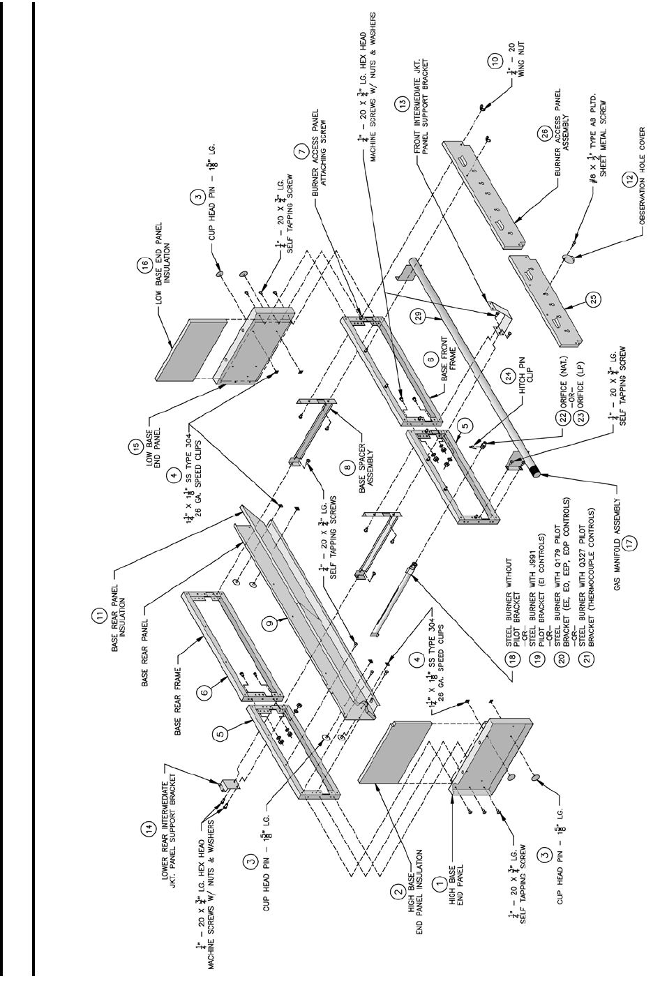
75
FIG. 59
BASE PARTS (5006B THRU 5014B)
SECTION VI - REPAIR PARTS (continued)

76
SECTION VI - REPAIR PARTS (continued)
TABLE 2A
SERIES 5B BASE PARTS - 5006B thru 5014B
Number in ( ) in Table Relates to Corresponding Number in in Figure 60
PART
NUMBER ITEM PART SIZE
BOILER SIZE
5006B 5007B 5008B 5009B 5010B 5011B 5012B 5013B 5014B
7181301 High Base End Panel 12-1/2 x 25-3/4 (1) (1) (1) (1) (1) (1) (1) (1) (1)
7201319 High Base End Panel Insul. - 1” Supertemp 12 x 21-1/2 (2) (2) (2) (2) (2) (2) (2) (2) (2)
80861551 Cup Head Pin CL #10 x 1-5/8” (3) (3) (3) (3) (3) (3) (3) (3) (3)
80861503 Speed Clip 1-1/4” x 1-1/8” SS Type 304 (4) (4) (4) (4) (4) (4) (4) (4) (4)
61813061 5006B Base Front and Rear Frame Assembly 12-1/2 x 27-3/16 (5) (5) & (6) (5)
61813071 5007B Base Front and Rear Frame Assembly 12-1/2 x 32-5/8 (5) (6) (5) & (6) (5)
61813081 5008B Base Front and Rear Frame Assembly 12-1/2 x 38-1/16 (5)
61813091 5009B Base Front and Rear Frame Assembly 12-1/2 x 43-1/2 (5)
61813101 5010B Base Front and Rear Frame Assembly 12-1/2 x 48-15/16 (5)
80861601 Burner Access Panel Attaching Screw (7) (7) (7) (7) (7) (7) (7) (7) (7)
6181301 Base Spacer Assembly 11 x 22-3/4 (8) (8) (8) (8)
71813062 5006B Base Rear Panel 9-5/8 x 26-15/16 (9)
71813072 5007B Base Rear Panel 9-5/8 x 32-3/8 (9)
71813082 5008B Base Rear Panel 9-5/8 x 37-13/16 (9)
71813092 5009B Base Rear Panel 9-5/8 x 43-1/4 (9)
71813102 5010B Base Rear Panel 9-5/8 x 48-11/16 (9)
71813112 5011B Base Rear Panel 9-5/8 x 54-1/8 (9)
71813122 5012B Base Rear Panel 9-5/8 x 59-9/16 (9)
71813132 5013B Base Rear Panel 9-5/8 x 65 (9)
71813142 5014B Base Rear Panel 9-5/8 x 70-7/16 (9)
72013065 Base Rear Panel Insulation - 1” Supertemp 8-3/4 x 26-15/16 (11) 1 pc
72013075 Base Rear Panel Insulation - 1” Supertemp 8-3/4 x 32-3/8 (11) 1 pc
72013085 Base Rear Panel Insulation - 1” Supertemp 8-3/4 x 18-7/8 (11) 2 pcs
72013095 Base Rear Panel Insulation - 1” Supertemp 8-3/4 x 21-5/8 (11) 2 pcs
72013105 Base Rear Panel Insulation - 1” Supertemp 8-3/4 x 24-5/16 (11) 2 pcs
72013115 Base Rear Panel Insulation - 1” Supertemp 8-3/4 x 29-3/4 (11) 2 pcs
72013125 Base Rear Panel Insulation - 1” Supertemp 8-3/4 x 35-3/16
7181312 Front Int. Panel Support Bracket (13) (13) (13) (13)
7181313 Lower Rear Int. Panel Support Bracket (14) (14) (14) (14)
7181302 Low Base End Panel 11-7/8 x 25-3/4 (15) (15) (15) (15) (15) (15) (15) (15) V
7201320 Low Base End Panel Insul. - 1” Supertemp 11-3/8 x 21-1/2 (16) (16) (16) (16) (16) (16) (16) (16) (16)
8221306 5006B Manifold 1-1/2 Pipe x
34-5/16 (17)
8221307 5007B Manifold (17)
8221308 5008B Manifold (17)
8221309 5009B Manifold (17)
8221310 5010B Manifold (17)
8221311 5011B Manifold (17)
8221312 5012B Manifold (17)
8821313 5013B Manifold (17)
8221314 5014B Manifold (17)
8231301 Main Burners without Pilot Bracket (18) (18) (18) (18) (18) (18) (18) (18) (18)
8231302 Or Main Burners w/J991 Pilot Bracket (EI Controls) (19) (19) (19) (19) (19) (19) (19) (19) (19)
8231303 Or Main Burners w/Q179 Pilot Bkt (EP Controls) (20) (20) (20) (20) (20) (20) (20) (20) (20)
8231304 Or Main Burners w/Q327 Pilot Bkt (Thermocouple Controls) (21) (21) (21) (21) (21) (21) (21) (21) (21)
822628 Main Gas Orices (Nat. Gas) - #40 Drill (22) (22) (22) (22) (22) (22) (22) (22) (22)
822629 Or Main Gas Orices (LP) - #55 Drill (23) (23) (23) (23) (23) (23) (23) (23) (23)
822604 Hitch Pin Clip (24) (24) (24) (24) (24) (24) (24) (24) (24)
61813062 5006B Burner Access Panel Assembly 7-1/4 x 26-15/16 (25) (25) & (26) (25)
61813072 5007B Burner Access Panel Assembly 7-1/4 x 32-3/8 (25) (26) (25) & (26) (25)
61813082 5008B Burner Access Panel Assembly 7-1/4 x 37-13/16 (25) (26)
61813092 5009B Burner Access Panel Assembly 7-1/4 x 43-1/4 (25)
61813102 5010B Burner Access Panel Assembly 7-1/4 x 48-11/16 (25)
7186001 Observation Hole Cover (12) (12) (12) (12) (12) (12) (12) (12) (12)
80860900 1/4 - 20 Wing Nut (10) (10) (10) (10) (10) (10) (10) (10) (10)
8201303 Low Base End to Right Section Fiberglass Rope 3/4 X 25-3/4
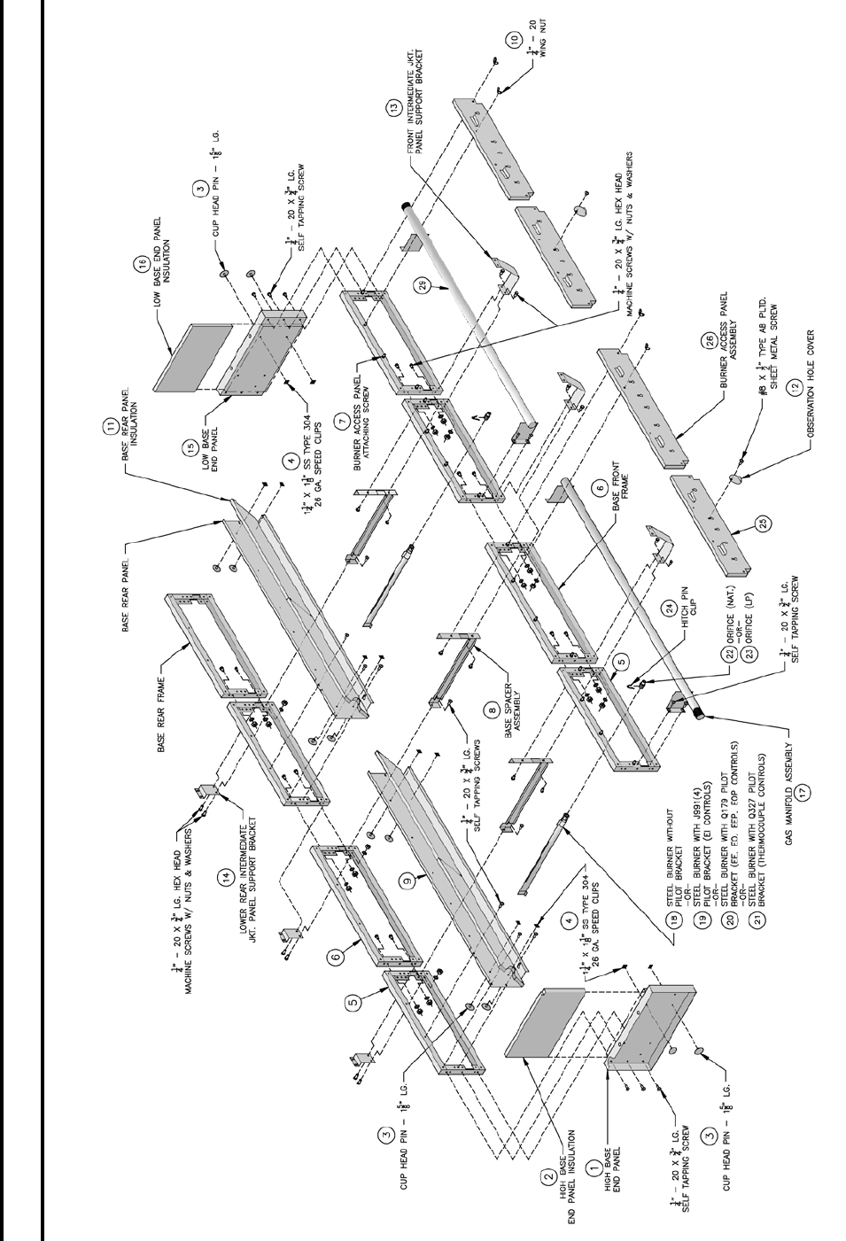
77
FIG. 60
BASE PARTS (5015B THRU 5026B)
SECTION VI - REPAIR PARTS (continued)

78
TABLE 2B
SERIES 5B BASE PARTS - 5015B Thru 5026B
Number in ( ) in Table Relates to Corresponding Number in in Figure 61
PART
NUMBER ITEM PART SIZE
BOILER SIZE
5015B 5016B 5017B 5018B 5019B 5020B 5021B 5022B 5024B 5026B
7181301 High Base End Panel 12-1/2 x 25-3/4 (1) (1) (1) (1) (1) (1) (1) (1) (1) (1)
7201319 High Base End Panel Insul. - 1” Thick 12 x 21-1/2 (2) (2) (2) (2) (2) (2) (2) (2) (2) (2)
80861551 Cup Head Pin CL #10 x 1-5/8” (3) (3) (3) (3) (3) (3) (3) (3) (3) (3)
80861503 Speed Clip 1-1/4” x 1-1/8” SS Type 304 (4) (4) (4) (4) (4) (4) (4) (4) (4) (4)
61813061 5006B Base Front and Rear Frame Assembly 12-1/2 x 27-3/16 (5) & (6) (5) (5)
61813071 5007B Base Front and Rear Frame Assembly 12-1/2 x 32-5/8 (6) (5) & (6) (6), (30) & (31) (5), (30) & (31)
61813081 5008B Base Front and Rear Frame Assembly 12-1/2 x 38-1/16 (5) & (6) (5) (6)
61813091 5009B Base Front and Rear Frame Assembly 12-1/2 x 43-1/2 (6) (5) & (6) (5)
61813101 5010B Base Front and Rear Frame Assembly 12-1/2 x 48-15/16 (6) (5) & (6) (30) (30) (30)
80861601 Burner Access Panel Attaching Screw (7) (7) (7) (7) (7) (7) (7) (7) (7) (7)
6181301 Base Spacer Assembly 11 x 22-3/4 (8) (8) (8) (8) (8) (8) (8) (8) (8) (8)
71813082 5008B Base Rear Panel 9-5/8 x 37-13/16 (9) & (32) (9)
71813092 5009B Base Rear Panel 9-5/8 x 43-1/4 (32) (9) & (32) (9)
71813102 5010B Base Rear Panel 9-5/8 x 48-11/16 (32) (9) & (32) (32) (32) (32)
71813112 5011B Base Rear Panel 9-5/8 x 54-1/8 (9)
71813122 5012B Base Rear Panel 9-5/8 x 59-9/16 (9)
71813132 5013B Base Rear Panel 9-5/8 x 65 (9) (32) (32)
71813142 5014B Base Rear Panel 9-5/8 x 70-7/16 (9)
72013065 Base Rear Panel Insulation - 1” Thick 8-3/4 x 26-15/16 (11) 2 pcs
72013075 Base Rear Panel Insulation - 1” Thick 8-3/4 x 32-3/8 (11) 2 pcs (11) 2 pcs (11) 2 pcs
72013085 Base Rear Panel Insulation - 1” Thick 8-3/4 x 18-7/8 (11) 4 pcs (11) 2 pcs
72013095 Base Rear Panel Insulation - 1” Thick 8-3/4 x 21-5/8 (11) 2 pcs (11) 4 pcs (11) 2 pcs
72013105 Base Rear Panel Insulation - 1” Thick 8-3/4 x 24-5/16 (11) 2 pcs (11) 2 pcs (11) 2 pcs (11) 2 pcs (11) 2 pcs
72013115 Base Rear Panel Insulation - 1” Thick 8-3/4 x 29-3/4 (11) 2 pcs (11) 2 pcs
72013125 Base Rear Panel Insulation - 1” Thick 8-3/4 x 35-3/16 (11) 2 pcs
7181312 Front Int. Panel Support Bracket (13) (13) (13) (13) (13) (13) (13) (13) (13) (13)
7181313 Lower Rear Int. Panel Support Bracket (14) (14) (14) (14) (14) (14) (14) (14) (14) (14)
7181302 Low Base End Panel 11-7/8 x 25-3/4 (15) (15) (15) (15) (15) (15) (15) (15) (15) (15)
7201320 Low Base End Panel Insul. - 1” Thick 11-3/8 x 21-1/2 (16) (16) (16) (16) (16) (16) (16) (16) (16) (16)
8221308 5008B Manifold 1-1/2 Pipe x 45-3/16 (17) & (29) (17)
8221309 5009B Manifold 1-1/2 Pipe x 50-5/8 (29) (17 & 29) (17)
8221310 5010B Manifold 1-1/2 Pipe x 56-1/6 (29) (17) & (29) (29) (29) (29)
8221311 5011B Manifold 1-1/2 Pipe x 61-1/2 (17)
8221312 5012B Manifold 1-1/2 Pipe x 66-15/16 (17)
8821313 5013B Manifold 1-1/2 Pipe x 72-3/8 (17) (29) (29)
8221314 5014B Manifold 1-1/2 Pipe x 77-13/16 (17)
8231301 Main Burners without Pilot Bracket (18) (18) (18) (18) (18) (18) (18) (18) (18) (18)
8231302 Or Main Burners w/Q3481B Pilot Bracket (EI Controls) (19) (19) (19) (19) (19) (19) (19) (19) (19) (19)
8231303 Or Main Burners w/Q179 Pilot Bkt (EP Controls) (20) (20) (20) (20) (20) (20) (20) (20) (20) (20)
8231304 Or Main Burners w/Q327 Pilot Bkt (Thermocouple Controls) (21) (21) (21) (21) (21) (21) (21) (21) (21) (21)
822628 Main Gas Orices (Nat. Gas) - #40 Drill (22) (22) (22) (22) (22) (22) (22) (22) (22) (22)
822629 Or Main Gas Orices (LP) - #55 Drill (23) (23) (23) (23) (23) (23) (23) (23) (23) (23)
822604 Hitch Pin Clip (24) (24) (24) (24) (24) (24) (24) (24) (24) (24)
61813062 5006B Burner Access Panel Assembly 7-1/4 x 26-15/16 (25) (25) & (26) (25)
61813072 5007B Burner Access Panel Assembly 7-1/4 x 32-3/8 (25) (26) (25) & (26) (26), (27) &
(28) (25), (27) & (28)
61813082 5008B Burner Access Panel Assembly 7-1/4 x 37-13/16 (25) & (26) (25) (25) (26)
61813092 5009B Burner Access Panel Assembly 7-1/4 x 43-1/4 (26) (25) & (26) (25)
61813102 5010B Burner Access Panel Assembly 7-1/4 x 48-11/16 (26) (25) & (26) (27) (27) (27)
7186001 Observation Hole Cover (12) (12) (12) (12) (12) (12) (12) (12) (12) (12)
80860900 1/4 - 20 Wing Nut (10) (10) (10) (10) (10) (10) (10) (10) (10) (10)
SECTION VI - REPAIR PARTS (continued)
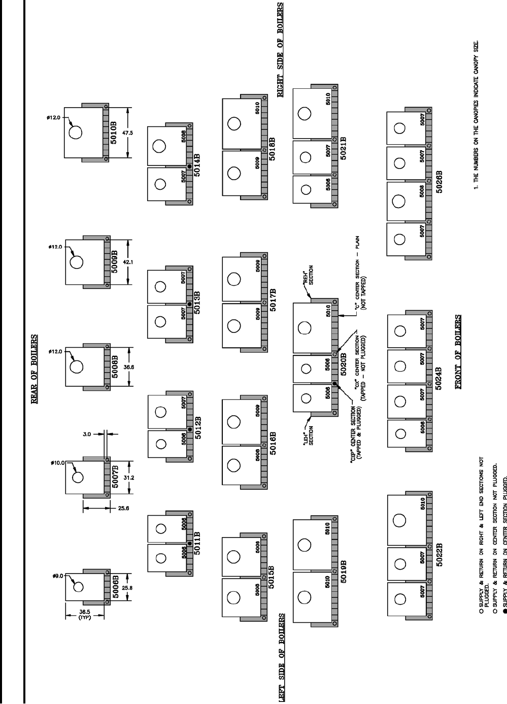
79
FIG. 61
INTEGRAL CANOPY DRAFT HOODS & SECTIONS
SECTION VI - REPAIR PARTS (continued)

80
TABLE 3A
SERIES 5B INTEGRAL CANOPY DRAFT HOODS - BOILER SIZES
PART SIZE PART NO. Canopy -
Draft Hood No.
BOILER SIZE (QUANTITY)
5006B 5007B 5008B 5009B 5010B
36-1/2 X 25-3/4 61113063 5006B (1) 1
36-1/2 X 31-3/16 61113073 5007B (2) 1
36-1/2 X 36-5/8 61113083 5008B (3) 1
36-1/2 X 41-1/16 61113093 5009B (4) 1
36-1/2 X 47-1/2 61113103 5010B (5) 1
5011B 5012B 5013B 5014B 5015B
36-1/2 X 25-3/4 61113063 5006B (1) 2 1
36-1/2 X 31-3/16 61113073 5007B (2) 1 2 1
36-1/2 X 36-5/8 61113083 5008B (3) 1 2
36-1/2 X 41-1/16 61113093 5009B (4)
36-1/2 X 47-1/2 61113103 5010B (5)
5016B 5017B 5018B 5019B 5020B
36-1/2 X 25-3/4 61113063 5006B (1) 3
36-1/2 X 31-3/16 61113073 5007B (2)
36-1/2 X 36-5/8 61113083 5008B (3) 1
36-1/2 X 41-1/16 61113093 5009B (4) 1 2 1
36-1/2 X 47-1/2 61113103 5010B (5) 1 2 1
5021B 5022B 5024B 5026B
36-1/2 X 25-3/4 61113063 5006B (1) 1 1
36-1/2 X 31-3/16 61113073 5007B (2) 1 2 3 3
36-1/2 X 36-5/8 61113083 5008B (3) 1
36-1/2 X 41-1/16 61113093 5009B (4)
36-1/2 X 47-1/2 61113103 5010B (5) 1 1
SECTION VI - REPAIR PARTS (continued)

81
TABLE 3B
SERIES 5B SECTION REPLACEMENT CHART
Refer to Fig. 61
PART NO. ITEM
BOILER SIZE (QUANTITY)
5006B 5007B 5008B 5009B 5010B 5011B 5012B 5013B 5014B 5015B 5016B 5017B 5018B 5019B 5020B 5021B 5022B 5024B 5026B
7171301 LEH Section (1) (1) (1) (1) (1) (1) (1) (1) (1) (1) (1) (1) (1) (1) (1) (1) (1) (1) (1)
7171303 C Center Section Plain (4) (5) (6) (7) (8) (8) (9) (10) (11) (12) (13) (14) (15) (16) (16) (17) (18) (19) (21)
7171302 REH Section (1) (1) (1) (1) (1) (1) (1) (1) (1) (1) (1) (1) (1) (1) (1) (1) (1) (1) (1)
7171304 CX Center Section Tapped
- Not Plugged (1) (1) (1) (1) (1) (1) (2) (2) (3) (3)
6171301 CXP Center Section Tapped
- Plugged (1) (1) (1) (1) (1)
806600023 Nipple Gauge, 3” & 7” (1) (1) (1) (1) (1) (1) (1) (1) (1) (1) (1) (1) (1) (1) (1) (1) (1) (1) (1)
8056254 Nipple Lubricant, Loctite®
#592, 50 ml (3) (3) (1) (1) (2) (2) (3) (3) (1) (2) (3)
8056255 Nipple Lubricant, Loctite®
#592, 250 ml (1) (1) (1) (1) (1) (1) (1) (1) (1) (1) (2) (2) (2) (2) (2) (2) (2)
SECTION VI - REPAIR PARTS (continued)

82
TABLE 3C
SERIES 5B BASE / PILOT ASSEMBLIES
5006B THRU 5014B BOILERS - SINGLE BASE REQUIRED
(NATURAL GAS) 5006B 5007B 5008B 5009B 5010B 5011B 5012B 5013B 5014B
Complete Base Ass’y w/EI Pilot Ass’y 618130642 618130742 618130842 618130942 618131042 618131142 618131242 618131342 618131442
Complete Base Ass’y w/Thermocouple Pilot Ass’y 618130651 618130751 618130851 618130951 618131051 618131151 618131251 618131351 618131451
Complete Base Ass’y w/EP Pilot Ass’y 618130611 618130711 618130811 618130911 618131011 618131111 618131211 618131311 618131411
(LP GAS)
Complete Base Ass’y w/Thermocouple Pilot Ass’y 618130661 618130761 618130861 618130961 618131061 618131161 618131261 618131361 618131461
(NATURAL GAS) 5015B 5016B 5017B 5108B 5109B 5020B 5021B 5022B 5024B 5026B
Right Base Subass’y w/EI Pilot Ass’y 618130852 618130952 618131052 618131052 618130952 618131052 618131052 618131052 618131352 618131352
Right Base Subass’y w/Thermocouple Pilot Ass’y 618130871 618130971 618130971 618131071 618131071 618131071 618131071 618131071 618131371 618131371
Right Base Subass’y w/EP Pilot Ass’y 618130821 618130921 618130921 618131021 618131021 618131021 618131021 618131021 618131321 618131321
Left Base Subass’y w/EI Pilot Ass’y 618131541 618131641 618131741 618131841 618131941 618132041 618132141 618131052 618131352 618131352
Left Base Subass’y w/Thermocouple Pilot Ass’y 61813159 61813169 61813179 61813189 61813199 61813209 61813219 61813229 61813249 61813269
Left Base Subass’y w/EP Pilot Ass’y 61813157 61813167 61813177 61813187 61813197 61813207 61813217 61813227 61813247 61813267
(LP GAS)
Right Base Subass’y w/Thermocouple Pilot Ass’y 618130881 618130971 618130971 618131071 618131071 618131071 618131071 618131071 618131371 618131371
Left Base Subass’y w/Thermocouple Pilot Ass’y 618131511 618131611 618131711 618131811 618131911 618132011 618132111 618132211 618132411 618132611
SECTION VI - REPAIR PARTS (continued)
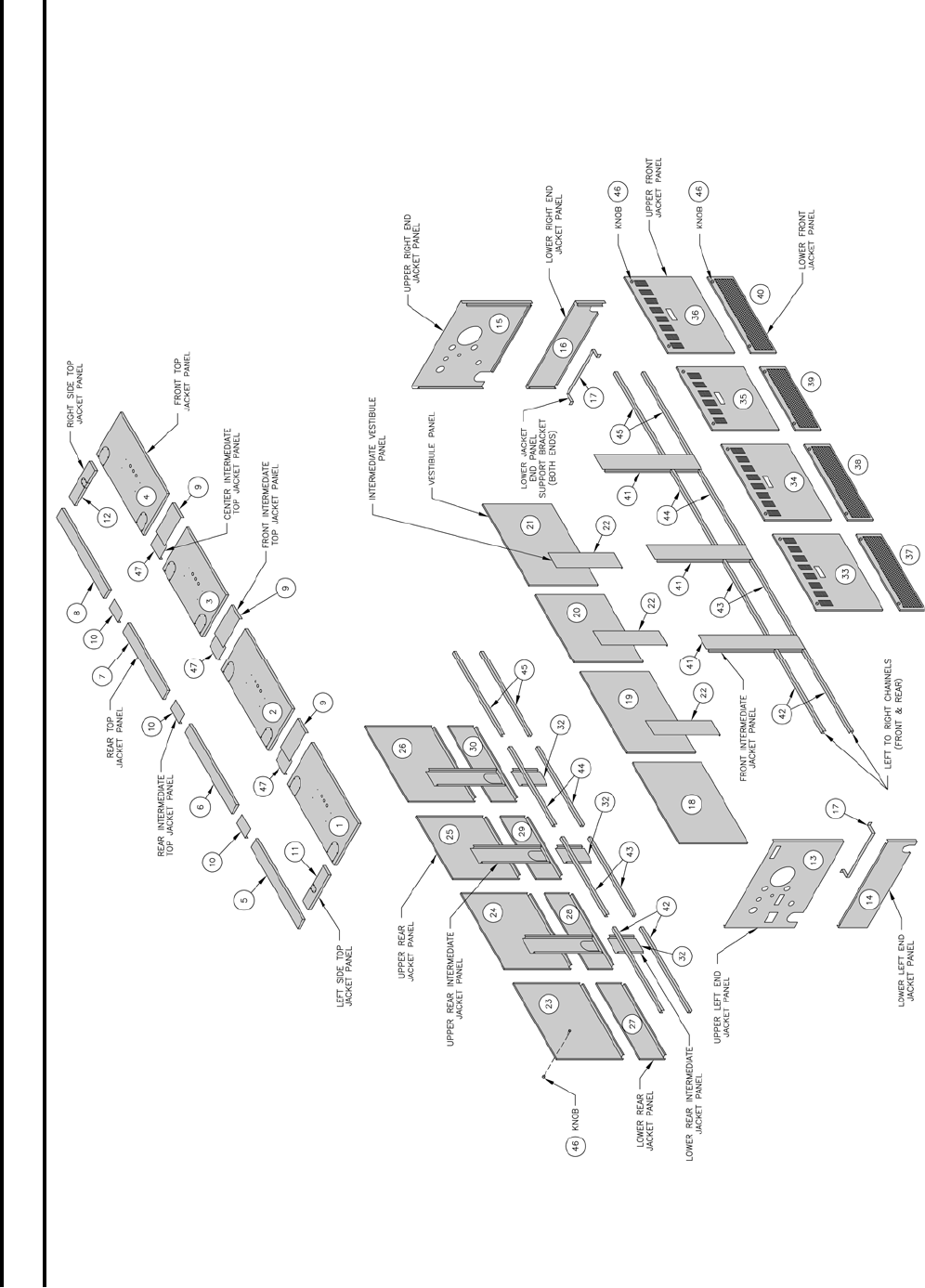
83
FIG. 62
JACKETS
SECTION VI - REPAIR PARTS (continued)

84
TABLE 4A
SERIES 5B JACKETS
Number in ( ) in Table Relates to Corresponding Number in in Figure 63
PART
NUMBER ITEM PART SIZE
BOILER SIZE
5006B 5007B 5008B 5009B 5010B 5011B 5012B 5013B 5014B 5015B
60413059 *5005B Front Top Panel 17-1/2 x 28-5/8 (1) & (2) (1)
60413069 5006B Front Top Panel 17-1/2 x 34-1/16 (1) (2) (1) & (2) (1)
60413079 5007B Front Top Panel 17-1/2 x 39-1/2 (1)
60413089 5008B Front Top Panel 17-1/2 x 44-15/16 (1)
60413099 5009B Front Top Panel 17-1/2 x 50-3/8 (1)
60413109 5010B Front Top Panel 17-1/2 x 55-13/16 (1)
7041316 Front Top Int. Panel 6-1/16 x 12 (9) (9) (9) (9) (9)
6041327 Center Top Int. Panel 6-1/16 x 6-7/8 (47) (47) (47) (27) (47)
6041328 Rear Top Int. Panel 3-25/32 x 6-1/16 (10) (10) (10) (10) (10)
60413052 *5005B Upper Rear Panel 24-1/2 x 26-5/16 (23) & (24) (24)
60413062 5006B Upper Rear Panel 24-1/2 x 31-3/4 (23) (23) (23) & (24) (23)
60413072 5007B Upper Rear Panel 24-1/2 x 37-3/16 (23) (24) (23) &
(24)
60413082 5008B Upper Rear Panel 24-1/2 x 42-5/8 (23)
60413092 5009B Upper Rear Panel 24-1/2 x 48-1/16 (23)
60413102 5010B Upper Rear Panel 24-1/2 x 53-1/2 (23)
60413053 *5005B Lower Rear Panel 9-1/2 x 26-5/16 (27) & (28) (27)
60413063 5006B Lower Rear Panel 9-1/2 x 31-3/4 (27) (28) (27) & (28) (27)
60413073 5007B Lower Rear Panel 9-1/2 x 37-3/16 (27)
60413083 5008B Lower Rear Panel 9-1/2 x 42-5/8 (27)
60413093 5009B Lower Rear Panel 9-1/2 x 48-1/6 (27)
60413103 5010B Lower Rear Panel 9-1/2 x 53-1/2 (27)
60413021 Upper Rear Int. Panel 7-5/16 x 25-1/2 (31) (31) (31) (31) (31)
60413031 Lower Rear Int. Panel 7-5/16 x 10-1/2 (32) (32) (32) (32) (32)
6041329 Upper Left End Panel 36 x 26 (13) (13) (13) (13) (13) (13) (13) (13) (13) (13)
60413071 Lower Left End Panel 36 x 10-1/2 (14) (14) (14) (14) (14) (14) (14) (14) (14) (14)
70413054 *5005B Upper Front Panel 24-1/2 x 26-5/16 (33) & (34) (33)
70413064 5006B Upper Front Panel 24-1/2 x 31-3/4 (33) (34) (33) & (34) (33)
70413074 5007B Upper Front Panel 24-1/2 x 37-6/16 (33) (34) (33) &
(34)
70413084 5008B Upper Front Panel 24-1/2 x 42-5/8 (33)
70413094 5009B Upper Front Panel 24-1/2 x 48-1/16 (33)
70413104 5010B Upper Front Panel 24-1/2 x 53-1/2 (33)
* For Multiple Usage Only
SECTION VI - REPAIR PARTS (continued)

85
TABLE 4B
SERIES 5B JACKETS
Number in ( ) in Table Relates to Corresponding Number in in Figure 63
PART
NUMBER ITEM PART SIZE
BOILER SIZE
5006B 5007B 5008B 5009B 5010B 5011B 5012B 5013B 5014B 5015B
60413055 *5005B Lower Top Panel 9-1/2 x 26-5/16 (37) & (37) (37)
60413065 5006B Lower Top Panel 9-1/2 x 31-3/4 (37) (38) (37) & (38) (37)
60413075 5007B Lower Top Panel 9-1/2 x 37-3/16 (37) (38) (37) & (38)
60413085 5008B Lower Top Panel 9-1/2 x 42-5/8 (37)
60413095 5009B Lower Top Panel 9-1/2 x 48-1/16 (37)
60413105 5010B Lower Top Panel 9-1/2 x 53-1/2 (37)
6041330 Upper Right End Panel 36 x 26 (15) (15) (15) (15) (15) (15) (15) (15) (15) (15)
60413051 Lower Right End Panel 36 x 10-1/2 (16) (16) (16) (16) (16) (16) (16) (16) (16) (16)
7041301 Lower End Panel Support Bkt. 1 x 21 (17) (17) (17) (17) (17) (17) (17) (17) (17) (17)
60413081 Front Int. Panel 36 x 7-5/16 (41) (41) (41) (41) (41)
604130510 *5005B Vestibule Panel 25 x 28-1/2 (18) & (19) (18)
604130610 5006B Vestibule Panel 25 x 33-15/16 (18) (19) (18) & (19) (18)
604130710 5007B Vestibule Panel 25 x 39-3/8 (18)
604130810 5008B Vestibule Panel 25 x 44-13/16 (18)
604130910 5009B Vestibule Panel 25 x 50-1/4 (18)
604131010 5010B Vestibule Panel 25 x 55-11/16 (18)
604130511 *5005B Rear Top Panel 3-3/4 x 28-5/8 (5) & (6) (5)
604130611 5006B Rear Top Panel 3-3/4 x 34-1/16 (5) (6) (5) & (6) (5)
604130711 5007B Rear Top Panel 3-3/4 x 39-1/2 (5)
604130811 5008B Rear Top Panel 3-3/4 x 44-15/16 (5)
604130911 5009B Rear Top Panel 3-3/4 x 50-3/8 (5)
604131011 5010B Rear Top Panel 3-3/4 x 55-13/16 (5)
6041331 Intermediate Vestibule Panel 24 x 6-1/8 (22) (22) (22) (22) (22)
6041332 Left Side Top Panel 3-7/8 x 14-13/16 (11) (11) (11) (11) (11) (11) (11) (11) (11) (11)
6041333 Right Side Top Panel 3-7/8 x 14-13/16 (12) (12) (12) (12) (12) (12) (12) (12) (12) (12)
7041302 #6 Left to Right Channel 1 x 33-15/16 (42)
7041303 #7 Left to Right Channel 1 x 39-3/8 (42)
7041304 #8 Left to Right Channel 1 x 44-13/16 (42)
7041305 #9 Left to Right Channel 1 x 50-1/4 (42)
7041306 #10 Left to Right Channel 1 x 55-11/16 (42)
7041307 #16 Left to Right Channel 1 x 30-9/16 (42) & (43) (42)
7041308 #17 Left to Right Channel 1 x 36 (43) (42) & (43) (42)
7041309 #18 Left to Right Channel 1 x 41-7/16 (43) (42) & (43)
80860926 Knobs Dimco - Black #516 (46) (46) (46) (46) (46) (46) (46) (46) (46) (46)
80860800 Machine Screw #10-32 x 3/16” Lg. Slotted Rd. Head (47) (47) (47) (47) (47) (47) (47) (47) (47) (47)
SECTION VI - REPAIR PARTS (continued)

86
TABLE 4C
SERIES 5B JACKETS
Number in ( ) in Table Relates to Corresponding Number in in Figure 63
PART
NUMBER ITEM PART SIZE
BOILER SIZE
5016B 5017B 5018B 5019B 5020B 5021B 5022B 5024B 5026B
60413049 *5004B Front Top Panel 17-1/2 x 23-3/16 (2)
60413059 *5005B Front Top Panel 17-1/2 x 28-5/8 (1) (1) & (2) (2) (1), (2) & (3) (3)
60413069 5006B Front Top Panel 17-1/2 x 34-1/16 (1) (4) (1), (2) & (4)
60413079 5007B Front Top Panel 17-1/2 x 39-1/2 (1)
60413089 5008B Front Top Panel 17-1/2 x 44-15/16 (2) (1) & (2) (1)
60413099 5009B Front Top Panel 17-1/2 x 50-3/8 (2) (1) & (2) (3) (3) (3)
60413109 5010B Front Top Panel 17-1/2 x 55-13/16
7041316 Front Top Int. Panel 6-1/16 x 12 (9) (9) (9) (9) (9) (9) (9) (9) (9)
6041327 Center Top Int. Panel 6-1/6 x 6-7/8 (47) (47) (47) (47) (47) (47) (47) (47) (47)
6041328 Rear Top Int. Panel 3-25/32 x 6-1/16 (10) (10) (10) (10) (10) (10) (10) (10) (10)
60413042 *5004B Upper Rear Panel 24-1/2 x 20-7/8 (24)
60413052 *5005B Upper Rear Panel 24-1/2 x 26-5/16 (23) (23) & (24) (24) (23), (24) & (25) (25)
60413062 5006B Upper Rear Panel 24-1/2 x 31-3/4 (23) (26) (23), (24) & (26)
60413072 5007B Upper Rear Panel 24-1/2 x 37-3/16 (23)
60413082 5008B Upper Rear Panel 24-1/2 x 42-5/8 (24) (23) & (24) (23) (23)
60413092 5009B Upper Rear Panel 24-1/2 x 48-1/16 (24) (23) & (24) (25) (25) (25)
60413043 *5004B Lower Rear Panel 9-1/2 x 20-7/8 (5) (28)
60413053 *5005B Lower Rear Panel 9-1/2 x 26-5/16 (5) (27) (27) & (28) (28) (27), (28) & (29) (29)
60413063 5006B Lower Rear Panel 9-1/2 x 31-3/4 (5) (27) (30) (27), (28) & (30)
60413073 5007B Lower Rear Panel 9-1/2 x 37-3/16 (27)
60413083 5008B Lower Rear Panel 9-1/2 x 48-1/16 (28) (27) & (28) (27)
60413093 5009B Lower Rear Panel 9-1/2 x 48-1/16 (28) (27) & (28) (29) (29) (29)
6041333 Right Side Top Panel 3-7/8 x 14-13/16 (12) (12) (12) (12) (12) (12) (12) (12) (12)
60413021 Upper Rear Int. Panel 7-5/16 x 25-1/2 (31) (31) (31) (31) (31) (31) (31) (31) (31)
60413031 Lower Rear Int. Panel 7-5/16 x 10-1/2 (32) (32) (32) (32) (32) (32) (32) (32) (32)
6041329 Upper Left End Panel 36 x 26 (13) (13) (13) (13) (13) (13) (13) (13) (13)
60413071 Lower Left End Panel 36 x 10-1/2 (14) (14) (14) (14) (14) (14) (14) (14) (14)
70413044 *5004B Upper Front Panel 24-1/2 x 20-7/8 (34)
70413054 *5005B Upper Front Panel 24-1/2 x 26-5/16 (33) (33) & (34) (34) (33), (34) & (35) (35)
70413064 5006B Upper Front Panel 24-1/2 x 31-3/4 (33) (37) (33), (34) & (36)
70413074 5007B Upper Front Panel 24-1/2 x 37-6/16 (33)
70413084 5008B Upper Front Panel 24-1/2 x 48-1/16 (34) (33) & (34) (35) (35) (35)
* For Multiple Usage Only
SECTION VI - REPAIR PARTS (continued)

87
TABLE 4D
SERIES 5B JACKETS
Number in ( ) in Table Relates to Corresponding Number in in Figure 63
PART
NUMBER ITEM PART SIZE
BOILER SIZE
5016B 5017B 5018B 5019B 5020B 5021B 5022B 5024B 5026B
60413045 *5004B Lower Front Panel 9-1/2 x 20-7/8 (38)
60413055 *5005B Lower Front Panel 9-1/2 x 26-5/16 (37) (37) & (38) (38) (40)
60413065 5006B Lower Front Panel 9-1/2 x 31-3/4 (37) (40) (37)
60413075 5007B Lower Front Panel 9-1/2 x 37-3/16 (37) (38)
60413085 5008B Lower Front Panel 9-1/2 x 42-5/8 (38) (37) & (38) (37)
60413095 5009B Lower Front Panel 9-1/2 x 48-1/16 (38) (37) & (38) (39) (39) (39)
6041330 Upper Right End Panel 36 x 26 (15) (15) (15) (15) (15) (15) (15) (15) (15)
60413051 Lower Right End Panel 36 x 10-1/2 (16) (16() (16) (16) (16) (16) (16) (16) (16)
604130410 *5004B Vestibule Panel 25 x 23-1/4 (19)
604130510 *5005B Vestibule Panel 25 x 28-1/2 (18) (18) & (19) (19) (18), (19) & (20) (20)
604130610 5006B Vestibule Panel 25 x 33-15/16 (23) (18) (21) (18), (19) & (21)
604130710 5007B Vestibule Panel 25 x 39-3/8 (18)
604130810 5008B Vestibule Panel 25 x 44-13/16 (19) (18) & (19) (18)
604130910 5009B Vestibule Panel 25 x 50-1/4 (19) (18) & (19) (20) (20) (20)
604131010 5010B Vestibule Panel 25 x 55-11/16
604130411 *5004B Rear Top Panel 3-3/4 x 23-3-16 (6)
604130511 *5005B Rear Top Panel 3-3/4 x 28-5/8 (5) (5) & (6) (6) (5), (6) & (7) (7)
604130611 5006B Rear Top Panel 3-3/4 x 34-1/16 (5) (8) (5), (6) & (8)
604130711 5007B Rear Top Panel 3-3/4 x 39-1/2 (5)
604130811 5008B Rear Top Panel 3-3/4 x 44-15/16 (6) (5) & (6) (5)
604130911 5009B Rear Top Panel 3-3/4 x 50-3/8 (6) (5) & (6) (7) (7) (7)
604131011 5010B Rear Top Panel 3-3/4 x 55-13/16
6041331 Intermediate Vestibule Panel 6-1/8 x 24 (22) (22) (22) (22) (22) (22) (22) (22) (22)
6041332 Left Side Top Panel 3-7/8 x 14-13/16 (11) (11) (11) (11) (11) (11) (11) (11) (11)
6041333 Right Side Top Panel 3-7/8 x 14-13/16 (12) (12) (12) (12) (12) (12) (12) (12) (12)
7041301 Lower End Panel Support Bkt. 1 x 21 (17) (17) (17) (17) (17) (17) (17) (17) (17)
60413081 Front Int. Panel 36 x 7-5/16 (41) (41) (41) (41) (41) (41) (41) (41) (41)
7041307 #16 Left to Right Channel 1 x 30-9/16 (42) (42) (42)
7041308 #17 Left to Right Channel 1 x 36 (42) (45) (42) & (45)
7041309 #18 Left to Right Channel 1 x 41-7/16 (42)
7041310 #19 Left to Right Channel 1 x 46-7/8 (43) (42) & (43) (42)
7041311 #20 Left to Right Channel 1 x 52-5/16 (43) (42) & (43) (44) (44) (44)
7041312 #26 Left to Right Channel 1 x 27-3/16 (43)
7041313 #27 Left to Right Channel 1 x 32-5/8 (43) (43) (43) & (44) (44)
7041314 #28 Left to Right Channel 1 x 38-1/16 (43)
80860926 Knobs Dimco - Black #516 (46) (46) (46) (46) (46) (46) (46) (46) (46)
80860800 Machine Screw #10 -32 x 3/16” Lg. Slotted Rd. Head (47) (47) (47) (47) (47) (47) (47) (47) (47)
TABLE 4E COMPLETE JACKETS
BOILER
SIZE
PART
NO.
BOILER
SIZE
PART
NO.
BOILER
SIZE PART NO. BOILER
SIZE PART NO. BOILER
SIZE PART NO. BOILER
SIZE PART NO.
5006B 60413068 5009B 60413098 5012B 60413128 5015B 60413158 5018B 60413188 5021B 60413218
5007B 60413078 5010B 60413108 5013B 60413138 5016B 60413168 5019B 60413198 5022B 60413228
5008B 60413088 5011B 60413118 5014B 60413148 5017B 61413178 5020B 60413208 5024B 60413248
SECTION VI - REPAIR PARTS (continued)
88
SECTION VI - REPAIR PARTS (continued)
TABLE 4F
Water Trim
Water Trim Carton Number: 7W2 7W3 7W4
Description 5006B-5011B 5012B-5022B 5024B-5026B PART NO.
Temperature Control, Honeywell L4006A2015 1 1 1 80160400
Immersion Well, Honeywell #123871A, 3/4” 1 1 1 80160452
Temperature Pressure Gauge, 100 PSI, 80-320°F, 1/2” NPT 1 1 1 8056028
Relief Valve Piping:
Nipple, 3/4” x 2” 1 1 806600003
Nipple, 1” x 2” 1 806600004
Nipple, 1-1/2” x 3” 1 1 1 806600006
Bushing, Hex, 1-1/2” x 3/4” 1 1 1 806600507
Elbow, Reducing, 1-1/2” x 3/4” x 90° 1 1 806601506
Elbow, Reducing, 1-1/2” x 1” x 90° 1 806601507
Relief Valve, ConBraCo #10-303-10, 3/4” x 3/4”, 50 psi 1 81660302
Relief Valve, ConBraCo #10-614-10, 3/4” x 1”, 50 psi 1 81660359
Relief Valve, ConBraCo #10-615-10, 1” x 1-1/4”, 50 psi 1 81660362
Plug extra tappings:
Plug, Pipe, 3/4” Countersunk 3 3 3 806603504
Plug, Pipe, 1-1/2” Countersunk 2 2 2 806603506
Plug, Pipe, 1/2” Countersunk 5 5 5 806603510
Plug, Pipe, 1” Countersunk 2 2 2 806603517

89
Steam Trim
Steam Trim Carton Number: 7S1 7S2 7S3 7S4
Description 5006B-5008B 5009B-5011B 5012B-5020B 5021B-5026B PART NO.
Pressuretrol, Honeywell L404F1060 1 1 1 1 80160942
Steam Gauge, 4" Dia., 30" -0-30 PSI, 1/4" 1 1 1 1 8056022
Gauge Glass Set, Conbraco #20-104-10 (6¾") 1 1 1 1 8056019
Safety Valve Piping:
Nipple, 1½" x 3”, Black 1 1 1 1 806600006
Elbow, Reducing, 1½” x ¾” x 90° 1 806601506
Elbow, Reducing, 1½” x 1” x 90° 1 806601507
Elbow, Reducing, 1½” x 1¼” x 90° 1 806601508
Elbow, 1½” x 90° 1 806601547
Safety Valve, ConBraCo #13-211-08, ¾”,
15 psi 1 81660500
Safety Valve, ConBraCo #13-202-08, 1” x 1”,
15 psi 1 81660501
Safety Valve, ConBraCo #13-213-08, 1¼” x
1½”, 15 psi 1 81660505
Safety Valve, Conbraco #13-214-08, 1½" x 2",
15 psi 1 81660503
Miscellaneous Fittings:
Coupling, Reducing, ½” x ¼” (Mount Syphon) 1 1 1 1 806602503
Extension Adapter, ½” FPT x ½” MPT
(Mount Gauge Glass) 2 2 2 2 806604501
Syphon, ¼” x 90° (Mount Pressuretrol) 1 1 1 1 8066030006
Elbow, street, ¼” x 90° (Mount Syphon) 1 1 1 1 806601509
Nipple, ½” x Close (Mount Syphon) 1 1 1 1 806600040
Plug Extra Tappings:
Plug, Pipe, ¾" Countersunk 2 2 2 2 806603504
Plug, Pipe, 1½" Countersunk 3 3 3 3 806603506
Plug, Pipe, ½" Countersunk 3 3 3 3 806603510
Plug, Pipe, 1" Countersunk 4 4 4 4 806603517
Lowest Permissible Water Level Plate 1 1 1 1 8141307
SECTION VI - REPAIR PARTS (continued)
TABLE 4G
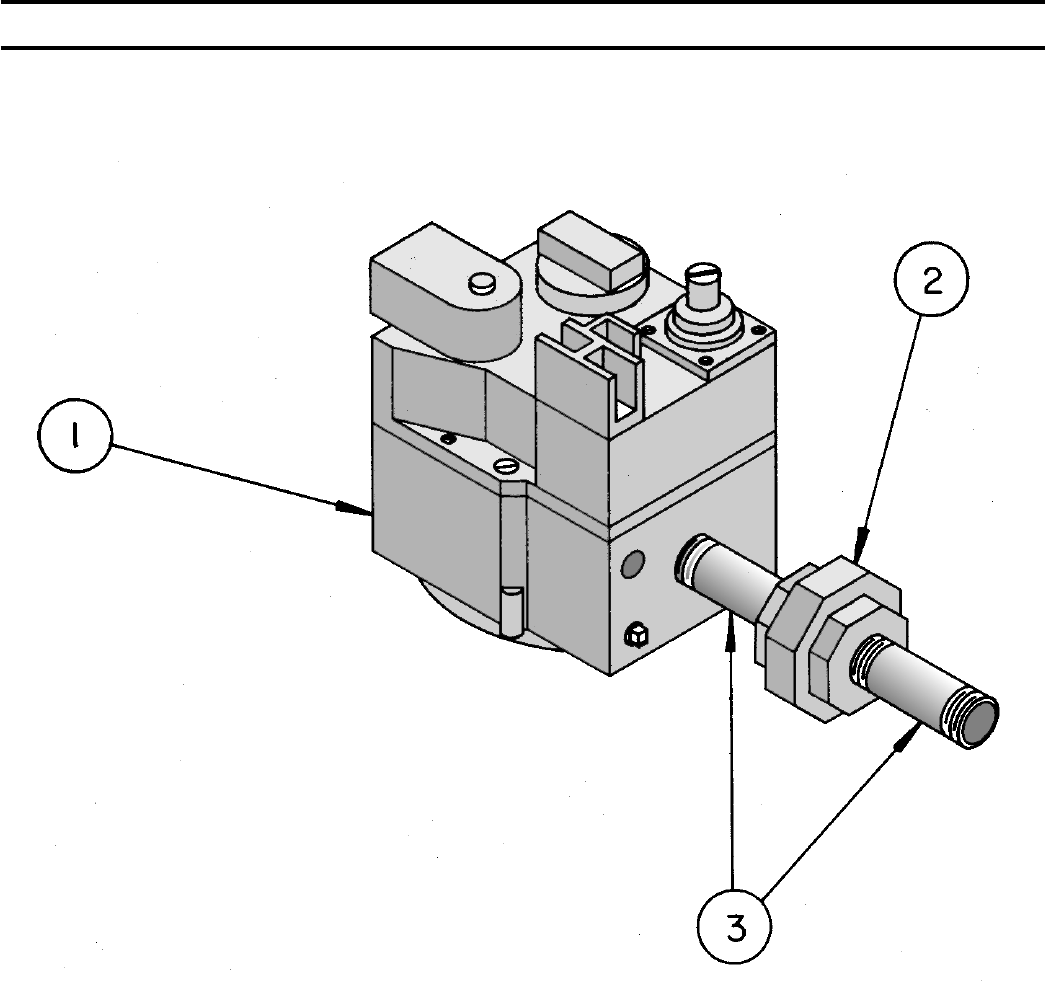
90
7000DERHC GAS TRAIN - EI - 5006B THRU 5009B - USA
PART NO. ITEM BOILER SIZE
5006B 5007B 5008B 5009B
81660151 Robertshaw 7000DERHC-S7C 1” x 1” Gas Valve (Nat.) (1) (1) (1) (1)
-- OR --
81660158 Robertshaw 7000DERHC-LP-S7C 1” x 1” Gas Valve (LP) (1) (1) (1) (1)
806604002 1” Ground Joint Union (2) (2) (2) (2)
806600027 1” x 3” Lg. -- Nipple (3) (3) (3) (3)
SECTION VI - REPAIR PARTS (continued)

91
V88A GAS TRAINS - USA
PART NO. ITEM BOILER SIZE
5006B - 5008B 5009B - 5014B 5015B 5016B 5017B - 5026B
Diaphragm Gas Valve
81660008 1” Honeywell V88A1618 1 --- 1 1 ---
81660009 1¼” Honeywell V88A1626 --- 1 --- 1 1
822605 Bleed Valve Assembly - Honeywell #126590 2 2 2 2 2
Nat. Gas Regulator - Std. Cad Plate Spring 3.0” x 6.0” WC
8226006 Maxitrol RV-61 1” x 1” 3A --- 3A 3A ---
822607 Maxitrol RV-81 1¼” x 1¼” --- 3A --- 3A 3A
LP Gas Regulator HO1 Blue Spring 5.5” to 12.0” WC
8226011 Maxitrol RV-61 1” x 1” 3B --- 3B 3B ---
8226012 Maxitrol RV-81 1¼” x 1¼” --- 3B --- 3B 3B
822614 Leak Limiter - Maxitrol #12A04 (incl. w / RV-61) 4 --- 4 4 ---
8226010 Leak Limiter - Maxitrol #12A34 (incl. w / RV-81) --- 4 --- 4 4
Manual Shutoff Valve
822615 ConBraCo 50-GB5-01A 1” x 1” 5 --- 5 5 ---
8226161 ConBraCo 50-GB6-01A 1¼” x 1¼” --- 5 --- 5 5
822645 Pilot Valve 6 6 6 6 6
SECTION VI - REPAIR PARTS (continued)
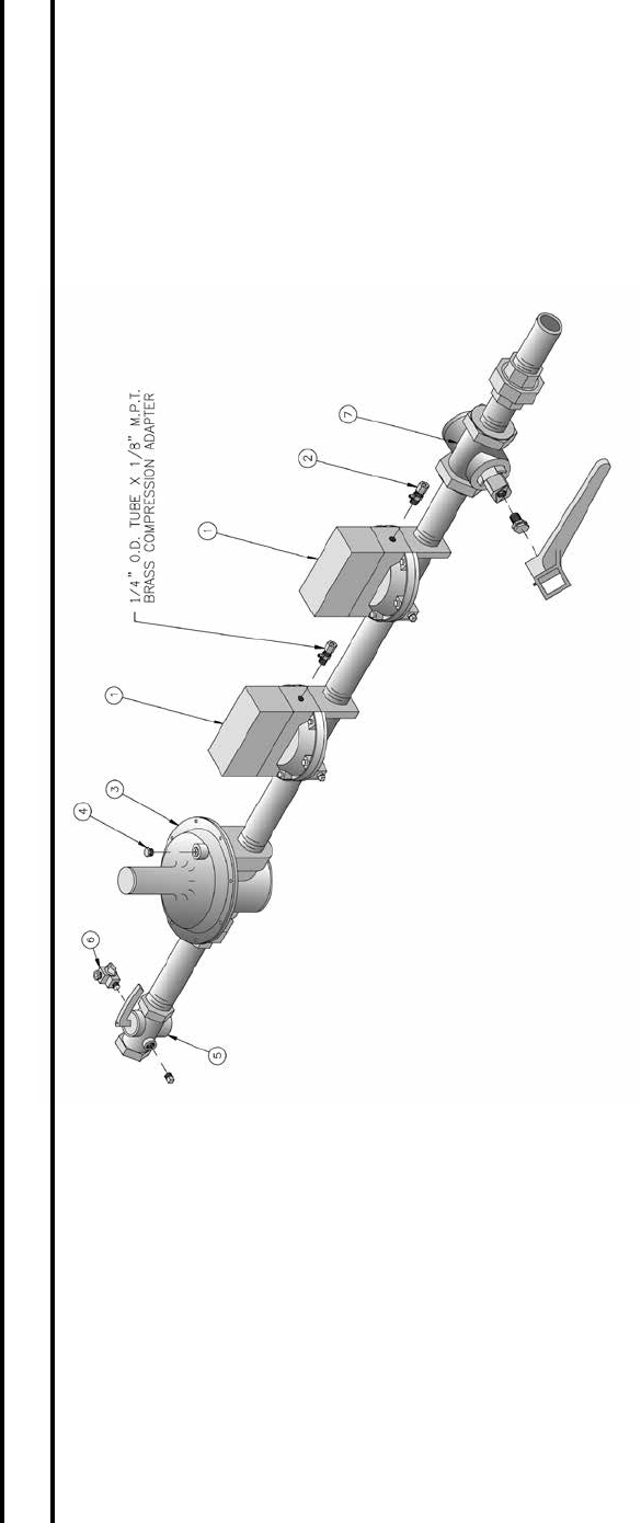
92
V88A GAS TRAINS - CANADA
NATURAL GAS ONLY
PART NO. ITEM BOILER SIZE
5006B - 5008B 5009B - 5014B 5015B 5016B 5017B - 5026B
Diaphragm Gas Valve
81660008 1” Honeywell V88A1618 1 --- 1 1 ---
81660009 1¼” Honeywell V88A1626 --- 1 --- 1 1
822605 Bleed Valve Assembly - Honeywell #126590 2 2 2 2 2
Nat. Gas Regulator - Std. Cad Plate Spring 3.0” x 6.0” WC
8226006 Maxitrol RV-61 1” x 1” 3 --- 3 3 ---
822607 Maxitrol RV-81 1¼” x 1¼” --- 3 --- 3 3
822614 Leak Limiter - Maxitrol #12A04 (incl. w / RV-61) 4 --- 4 4 ---
8226010 Leak Limiter - Maxitrol #12A34 (incl. w / RV-81) --- 4 --- 4 4
Manual Shutoff Valve
822615 ConBraCo 50-GB5-01A 1” x 1” 5 --- 5 5 ---
8226161 ConBraCo 50-GB6-01A 1¼” x 1¼” --- 5 --- 5 5
822645 Pilot Valve 6 6 6 6 6
Lubricated Plug Valve
822619 Newman-Milliken 200M - 1” 7 --- 7 7 ---
822620 Newman-Milliken 200M - 1¼” --- 7 --- 7 7
SECTION VI - REPAIR PARTS (continued)
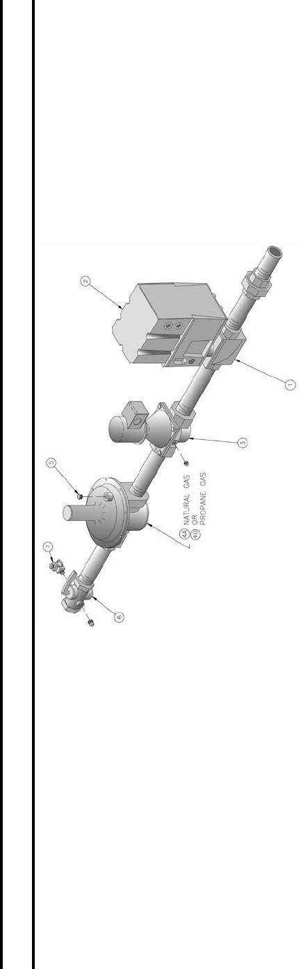
93
FLUID POWER GAS TRAINS - USA
(See Page 94 for “LO-HI-LO” Natural Gas Diaphragm Type Valves)
PART NO. ITEM BOILER SIZE
5006B - 5008B 5009B - 5014B 5015B 5016B 5017B - 5026B
Fluid Power Gas Valve
81660010 1” - Honeywell V5055B1002 1 --- 1 1 ---
81660011 1¼” - Honeywell V5055B1010 --- 1 --- 1 1
Actuators for Fluid Power Valves
81660012 “Lo-Hi-Off” Honeywell V4055A1007 - 5026B Sec. Opening Time - 120V 60HZ
81660013 “Lo-Hi-Lo” Honeywell V4062A1008 - 5026B Sec. Opening Time - 120V 60HZ
81660014 “Modulating” Honeywell V9055A1055 - 5026B Sec. Opening Time - 120V 60HZ
Solenoid Gas Valve
81660088 1” - ITT Gen. K3A562 3 --- 3 3 ---
81660086 1¼” - ITT Gen. K3A772 --- 3 --- 3 3
Nat. Gas Regulator - Std. Cad Plate Spring 3.0” x 6.0” WC
8226006 Maxitrol RV-61 1” x 1” 4A --- 4A 4A ---
8226012 Maxitrol RV-81 1¼” x 1¼” --- 4A --- 4A 4A
LP Gas Regulator HO1 Blue Spring 5.5” to 12.0” WC
8226011 Maxitrol RV-61 1” x 1” 4B --- 3B 3B ---
8226012 Maxitrol RV-81 1¼” x 1¼” --- 4B --- 4B 4B
822614 Leak Limiter - Maxitrol #12A04 (included w/ RV-61) 5 --- 5 5 ---
8226010 Leak Limiter - Maxitrol #12A34 (included w/ RV-81) --- 5 --- 5 5
Manual Shutoff Valve
822615 ConBraCo 50-GB5-01A 1” x 1” 6 --- 6 --- ---
8226161 ConBraCo 50-GB6-01A 1¼” x 1¼” --- 6 --- 6 6
822645 Pilot Valve 7 7 7 7 7
SECTION VI - REPAIR PARTS (continued)
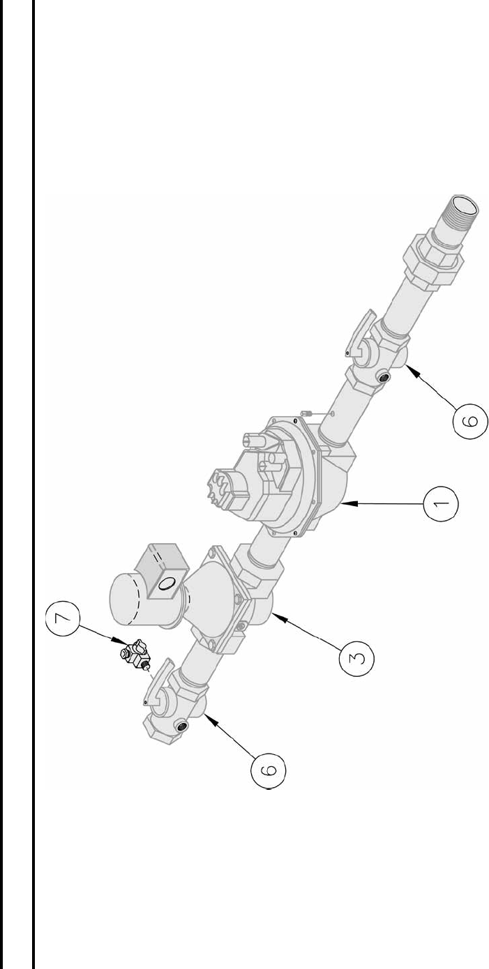
94
DIAPHRAGM VALVE “LO-HI-LO” GAS TRAIN
USA - NATURAL GAS ONLY
PART NO. ITEM BOILER SIZE
5006B 5009B 5015B 5016B 5017B
“Lo-Hi-Lo” Gas Valve
81660149 1” Honeywell V8944B1019 1 --- 1 1 ---
81660150 1¼” Honeywell V8944B1027 --- 1 --- 1 1
Solenoid Gas Valve
81660081 1” - ITT Gen. K8A461 3 --- 3 3 ---
81660094 1¼” - ITT Gen. K8A771 --- 3 --- 3 3
Manual Shutoff Valve
822615 ConBraCo 50-GB5-01A 1” x 1” 6 --- 6 6 ---
8226161 ConBraCo 50-GB6-01A 1¼” x 1¼” --- 6 --- 6 6
822645 Pilot Valve 7 7 7 7 7
SECTION VI - REPAIR PARTS (continued)
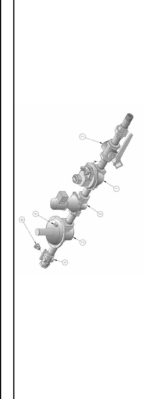
95
DIAPHRAGM VALVE “LO-HI-LO” GAS TRAIN
CANADA - NATURAL GAS ONLY
PART NO. ITEM BOILER SIZE
5006B - 5008B 5009B - 5014B 5015B 5016B 5017B - 5026B
“Lo-Hi-Lo” Gas Valve
81660149 1” Honeywell V8944B1019 1 --- 1 1 ---
81660150 1¼” Honeywell V8944B1027 --- 1 --- 1 1
Solenoid Gas Valve
81660081 1” - ITT Gen. K8A461 3 --- 3 3 ---
81660094 1¼” - ITT Gen. K8A771 --- 3 --- 3 3
Nat. Gas Regulator - Std. Cad Plate Spring 3.0” x 6.0” WC
8226006 Maxitrol RV-61 1” x 1” 3 --- 3 3 ---
8226012 Maxitrol RV-81 1¼” x 1¼” --- 3 --- 3 3
LP Gas Regulator HO1 Blue Spring 5.5” to 12.0” WC
8226011 Maxitrol RV-61 1” x 1” 3 --- 3 3 ---
8226012 Maxitrol RV-81 1¼” x 1¼” --- 3 --- 3 3
Leak Limiter
822614 Maxitrol #12A04 (included w/ RV-61) 4 --- 4 4 ---
8226010 Maxitrol #12A34 (included w/ RV-81) --- 4 --- 4 ---
Manual Valve
822615 ConBraCo 50-GB5-01A 1” x 1” 5 --- 5 5 ---
8226161 ConBraCo 50-GB6-01A 1¼” x 1¼” --- 5 --- 5 5
Pilot Valve
822645 1/8”MPT x ¼” OD Tube 6 6 6 6 6
Manual Valve
822619 Newman-Milliken 200M - 1” 7 --- 7 7 ---
822620 Newman-Milliken 200M - 1¼” --- 7 --- 7 7
SECTION VI - REPAIR PARTS (continued)

96
FLUID POWER GAS TRAINS - CANADA
PART NO. ITEM BOILER SIZE
5006B - 5008B 5009B - 5014B 5015B 5016B 5017B - 5026B
Fluid Power Gas Valve
81660010 1” - Honeywell V5055B1002 1 --- 1 1 ---
81660011 1¼” - Honeywell V5055B1010 --- 1 --- 1 1
Actuators for Fluid Power Valves
81660012 “Lo-Hi-Off” Honeywell V4055A1007 - 5026B Sec. Opening Time - 120V 60HZ
81660013 “Lo-Hi-Lo” Honeywell V4062A1008 - 5026B Sec. Opening Time - 120V 60HZ - LP Only
81660014 “Modulating” Honeywell V9055A1055 - 5026B Sec. Opening Time - 120V 60HZ
Solenoid Gas Valve
81660088 1” - ITT Gen. K3A562 3 --- 3 3 ---
81660094 1¼” - ITT Gen. K3A772 --- 3 --- 3 3
Nat. Gas Regulator - Std. Cad Plate Spring 3.0” x 6.0” WC
8226006 Maxitrol RV-61 1” x 1” 4A --- 4A 4A ---
822607 Maxitrol RV-81 1¼” x 1¼” --- 4A --- 4A 4A
LP Gas Regulator HO1 Blue Spring 5.5” to 12.0” WC
8226011 Maxitrol RV-61 1” x 1” 4B --- 3B 3B ---
8226012 Maxitrol RV-81 1¼” x 1¼” --- 4B --- 4B 4B
822614 Leak Limiter - Maxitrol #12A04 (included w/ RV-61) 5 --- 5 5 ---
8226010 Leak Limiter - Maxitrol #12A34 (included w/ RV-81) --- 5 --- 5 5
Manual Shutoff Valve
822615 ConBraCo 50-GB5-01A 1” x 1” 6 --- 6 6 ---
8226161 ConBraCo 50-GB6-01A 1¼” x 1¼” --- 6 --- 6 6
822645 Pilot Shutoff Valve 7 7 7 7 7
822619 Newman-Milliken 200M - 1” 8 --- 8 8 ---
822620 Newman-Milliken 200M - 1¼” --- 8 --- 8 8
SECTION VI - REPAIR PARTS (continued)
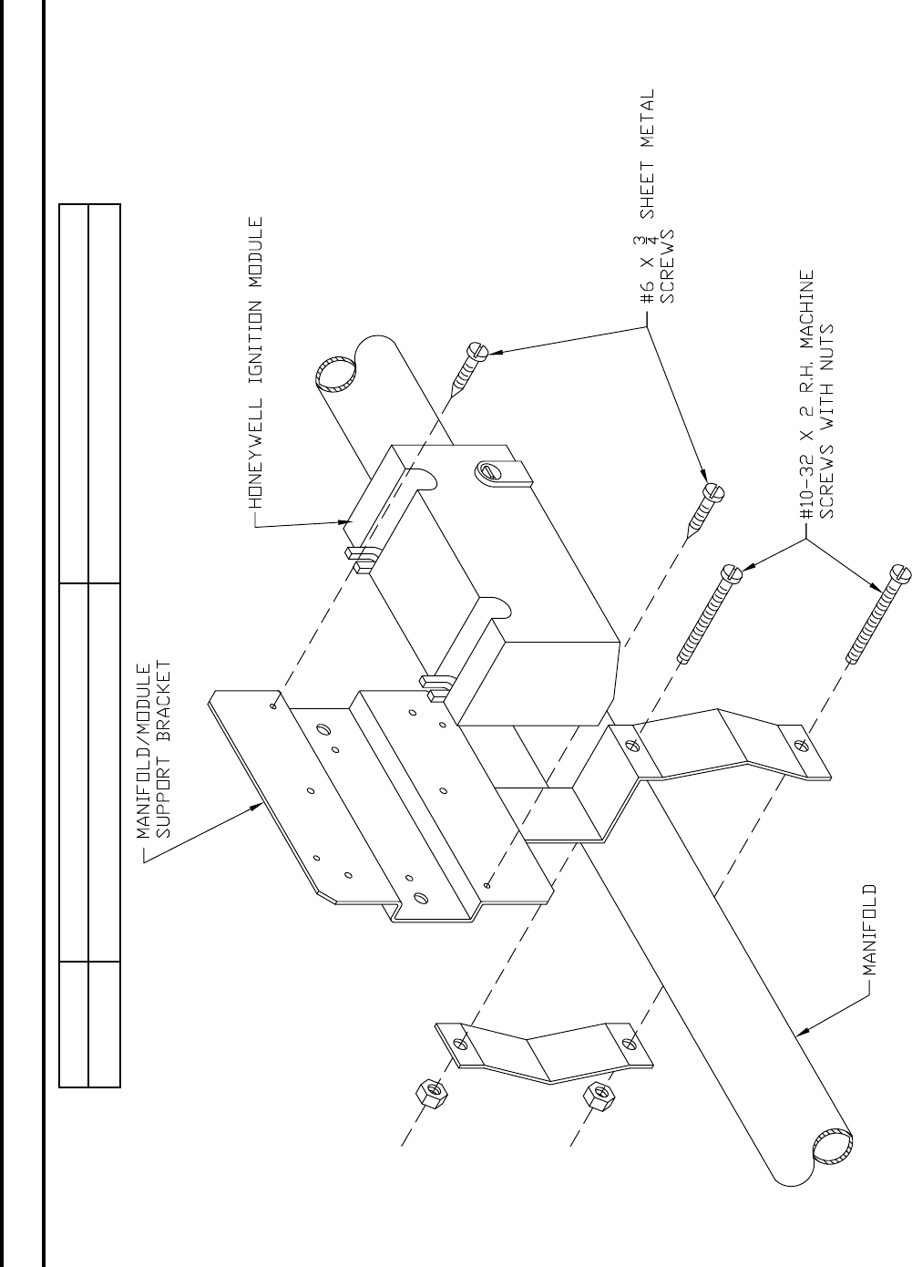
97
PART NO. 6011301 100958-01
Description Manifold Module Support Bracket Assembly Honeywell S8610M3009 Ignition Module
IGNITION MODULE #S8610M & SUPPORT BRACKET
EI CONTROL SYSTEM
SECTION VI - REPAIR PARTS (continued)
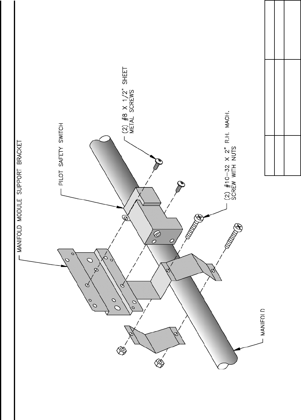
98
PILOTSTAT #L62GB & SUPPORT BRACKET
THERMOCOUPLE CONTROL SYSTEM
SECTION VI - REPAIR PARTS (continued)
ITEM (1) (2)
PART NO. 6011301 80160138
Description Manifold Module Support
Bracket Assembly
L62GB-3C
Pilot Safety Switch
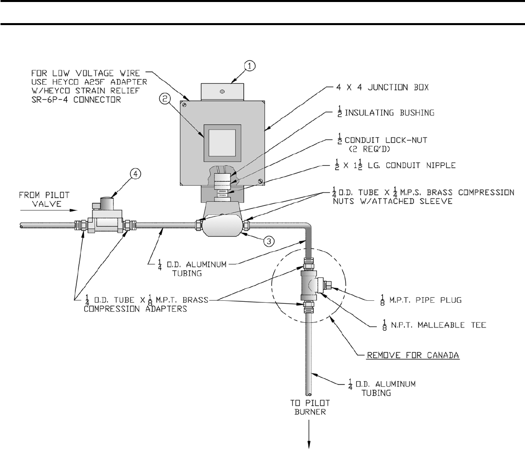
99
TRANSFORMER, PENN #H91WG PILOT SOLENOID VALVE & PILOT LINE REGULATOR
EI CONTROL SYSTEM
U.S.A. - 5010B-5026B NAT. GAS
CANADA - 5006B-5026B NAT. GAS
PART NO. ITEM
7136001 (1) “J” Box Mounting Bracket 24V 100 VA Transformer - 120 60HZ Primary
80160016 (2) Penn Y64T22-0 Plate Mounted
822666 (3) Penn Pilot Solenoid Valve H91WG-6
8226005 Pilot Line Regulator
Nat. Gas - Maxitrol RV-12-LT w/orange spring 4” to 8” WC
8136037 Heyco A25F Strain Relief Adaptor
8136038 Heyco Strain Relief Bushing SR-6P-4
SECTION VI - REPAIR PARTS (continued)
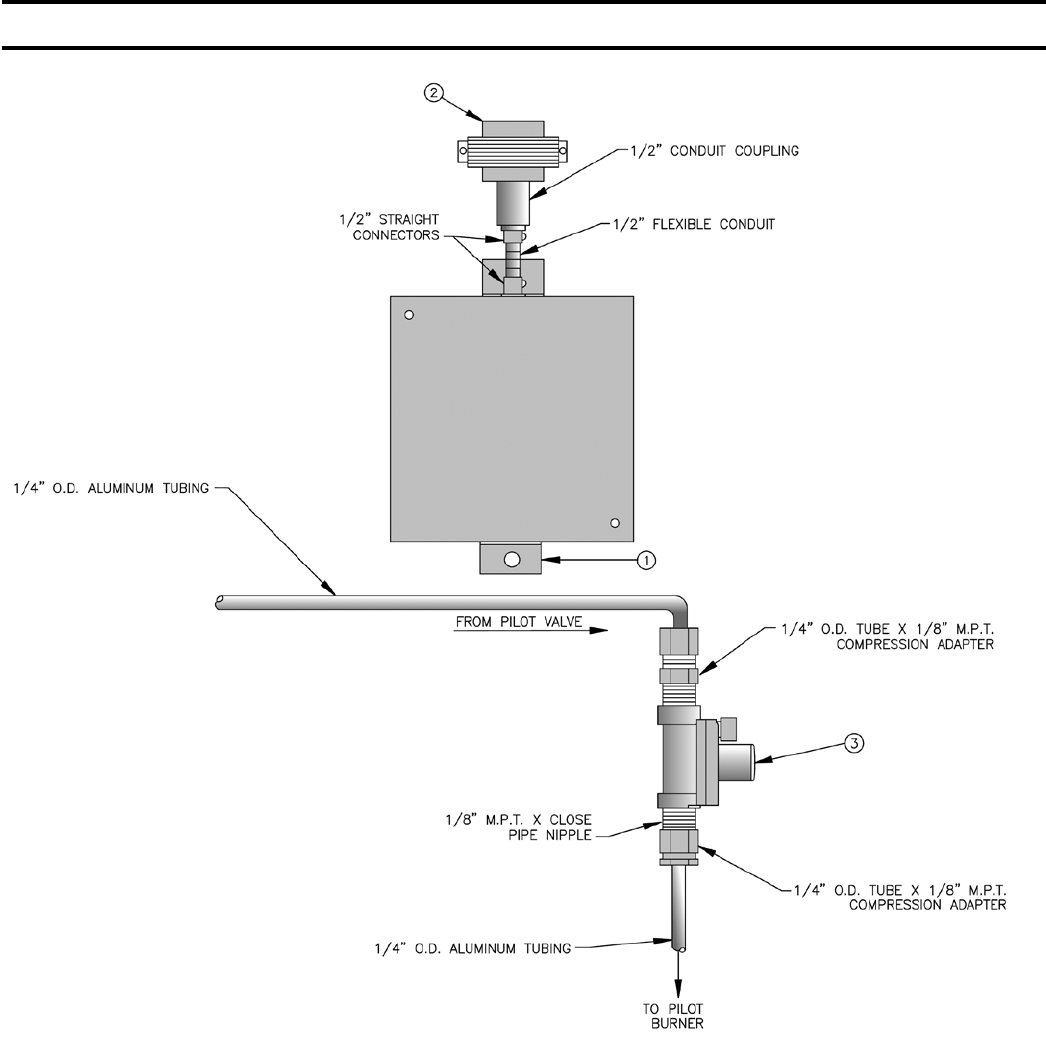
100
TRANSFORMER & PILOT LINE REGULATOR
THERMOCOUPLE CONTROL SYSTEM - CANADA
PART NO. ITEM
7016001 (1) “J” Box Mounting Bracket
24V - 40 VA Transformer - 120 60HZ Primary
80160039 (2A) USA - Honeywell Plate Mounted AT140D1012
80160014 (2B) Canada - Honeywell Foot Mounted AT72D1089
8226005 (3) Pilot Line Regulator
Nat. Gas - Maxitrol RV-12-LT w/orange spring 4” to 8” WC
SECTION VI - REPAIR PARTS (continued)
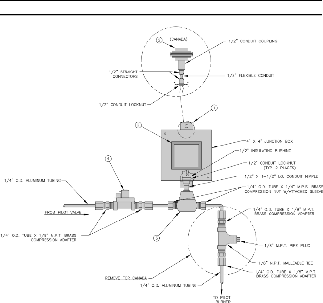
101
TRANSFORMER, PENN #H91WA-4 PILOT SOLENOID VALVE & PILOT LINE REGULATOR
EP CONTROL SYSTEM
PART NO. ITEM
7016003 (1) EP Control Mounting Bracket
24V - 40 VA Transformer - 120V 60HZ Primary
80160039 (2A) USA - Honeywell Plate Mounted AT140D1012
80160014 (2B) Canada - Honeywell Foot Mounted AT72D1089
822662 (3) Penn Pilot Solenoid Valve H91WA-4, 120V
8226005 (4) Nat. Gas - Maxitrol RV-12-LT w/orange spring 4” to 8” WC
80160018 Webster 612-6A7 Ignition Transformer (not shown)
SECTION VI - REPAIR PARTS (continued)
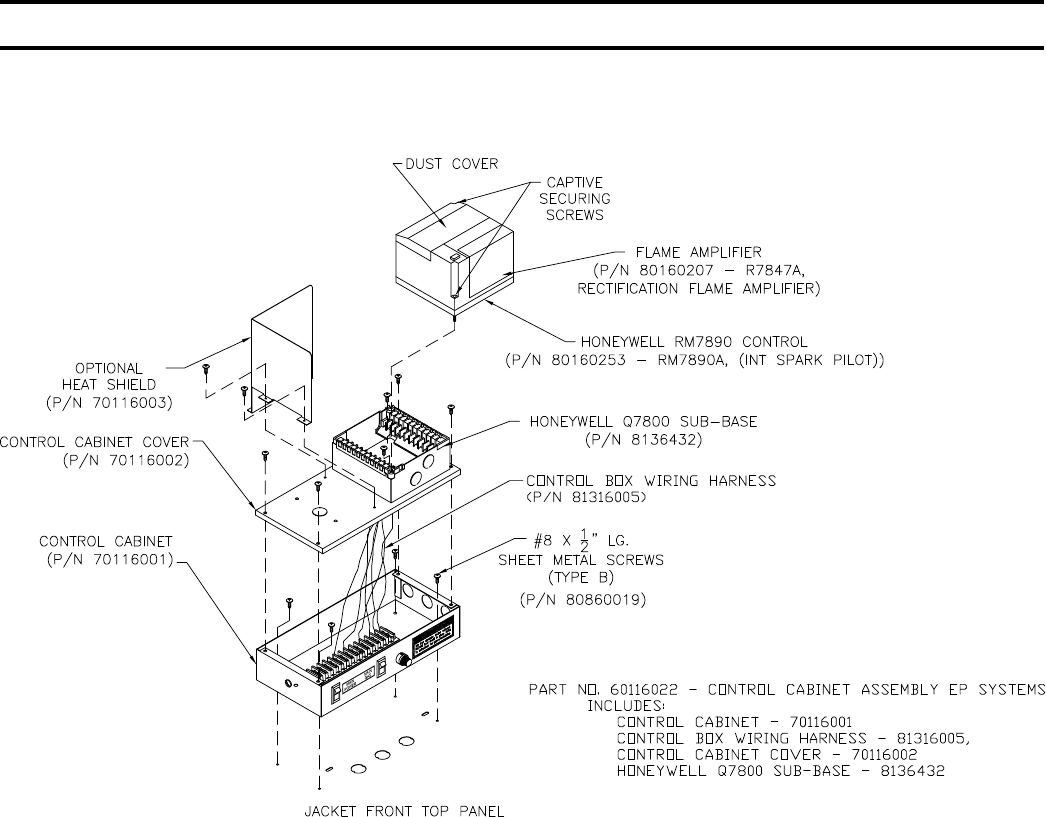
102
CONTROL ASSEMBLY AND MOUNTING BRACKET
EP CONTROL SYSTEMS
SECTION VI - REPAIR PARTS (continued)
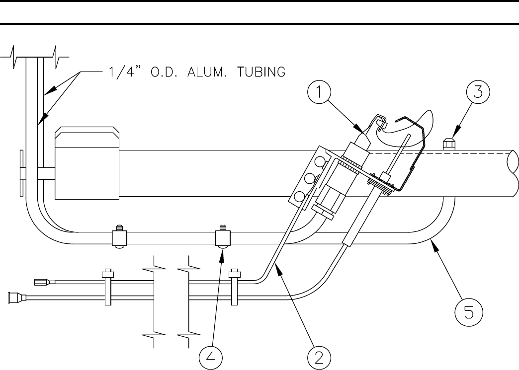
103
EI CONTROL SYSTEM - HONEYWELL Q3481 PILOT ASSEMBLY
EI CONTROL SYSTEM - PILOT ASSEMBLY
6236072 EI - 1, NAT., 5006B - 5009B Sections
6236075 EI - 1, LP., 5006B - 5009B Sections
6236076 EI - 2, NAT., 5010B - 5026B Sections
Not Available ........LP, 5010B - 5026B Sections
PART NO. ITEM
103704-01 (1) Pilot Burner/Igniter/Sensor Honeywell Q3481B1206, Nat. Gas with NE24 orice
100332-01 (1) Pilot Burner/Igniter/Sensor Honeywell Q3481B1180, LP Gas with KR14 orice
6136054 (2) Pilot Ground Wire Assembly, 36” (5006B - 5009B)
6137375 (2) Pilot Ground Wire Assembly, 72” (5010B - 5026B)
8236015 (3) Vent Tube Tip (USA Only) (5010B - 5026B Sections Only)
8236016 (4) Vent Tube Clip - Tinnerman C4886A4-27 (USA Only) (5010B - 5026B Sections Only)
8236048 (5) Vent Tube - ¼” x 18” Long Aluminum Tubing
For Canada, Omit Vent Tube, Vent Tube Tip and Vent Tube Clips. These items are not
used on 5006B - 5009B Sections, Robertshaw Gas Valves - USA.
SECTION VI - REPAIR PARTS (continued)
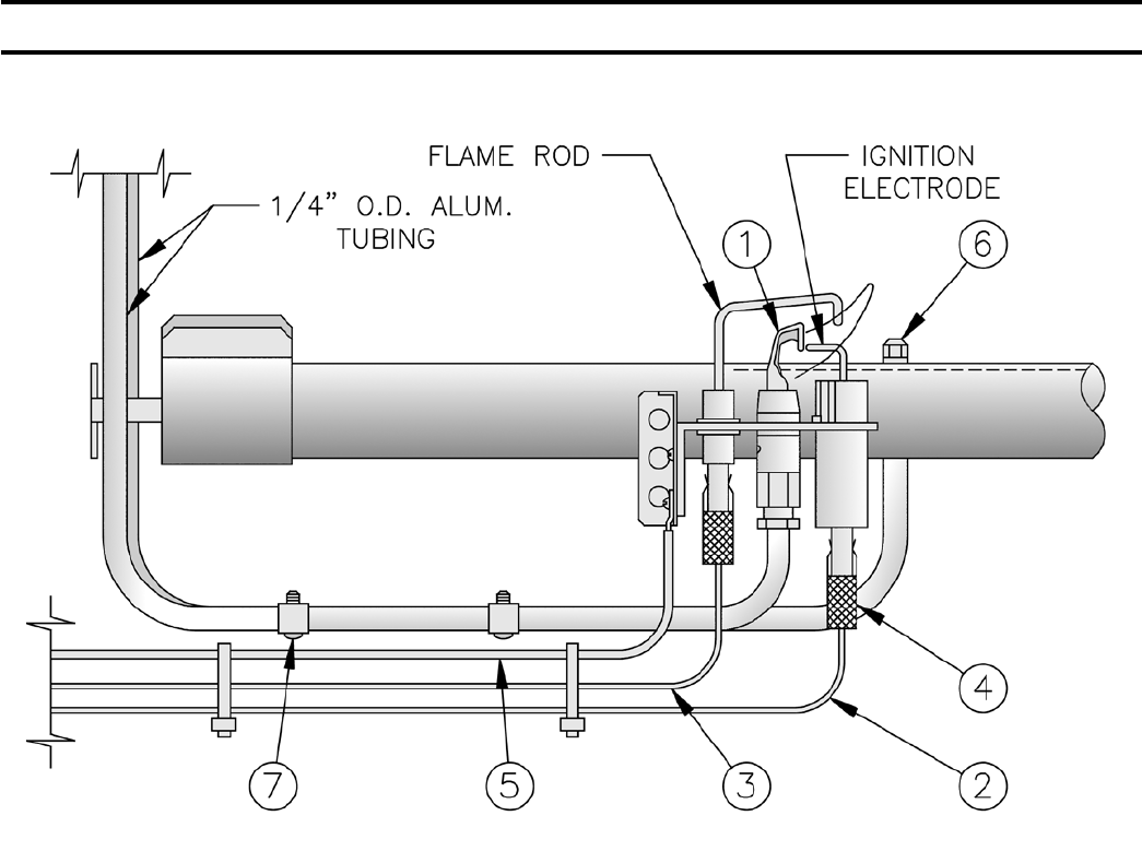
104
EP CONTROL SYSTEM - PILOT ASSEMBLY
6236003 NAT. GAS
Not Available for LP
PART NO. ITEM
8236017 (1) Flame Rectication Pilot Ass’y
Natural Gas - Honeywell Q179C1009 w/388146 AG Orice
7136255 (2) Ignition Lead - Honeywell R1061012 - 6’ Long
7136256 (3) Flame Rod Lead - Honeywell R1298020 - 6’ Long
8236021 (4) Female Rajah Connector - Honeywell 37356
6236020 (5) Ground Wire - Continental SRGX-600 200°C - Green - 72” Long
8236015 (6) Vent Tube Tip - (USA Only)
8236016 (7) Vent Tube Clip - Tinnerman C4886A4-27 (USA Only)
SECTION VI - REPAIR PARTS (continued)

105
APPENDIX A - FIGURES
Figure
Number
Page
Number Description
Section I - Equipment Check List
USA
KD Boilers 5 & 6 U.S.A. Equipment Check List
Canada
KD Boilers 7 & 8 Canadian Equipment Check List
Fig. 1 9 Dimensional Data
Section II - General Information
Section III - Installation Instructions
Fig. 2 11 Single Manifold Base 5006B Thru 5014B Section Boilers
Fig. 3 12 Dual Manifold Bases - 5015B Thru 5026B Section Boilers
Fig. 4 12 LEH Section on Base
Fig. 5 12 Assembly of Center Sections
Fig. 6 13 Arrangement of Sections and Canopy(s)
Fig. 7 14 Purpose of Tappings and Their Locations
Fig. 8 15 Installation of Built-in Heater
Fig. 9 15 Testing Boiler Assembly for Leaks
Fig. 10 16 Sealing of Base, Installation of Flue Covers and Canopies
Fig. 11 16 Attachment of Flue Covers
Fig. 12 17 Recommended Steam Boiler Piping, Gravity Return, 1 or 2 Supply Connections - 5006B Thru 5014B Section Boilers
Fig. 13 18 Recommended Steam Boiler Piping, Gravity Return, 3 Supply Connections - 5015B Thru 5020B Section Boilers
Fig. 14 19 Recommended Steam Boiler Piping, Gravity Return, 4 or 5 Supply Connections - 5021B Thru 5026B Section Boilers
Fig. 15 20 Typical Steam Piping Arrangement for Boilers with Pumped Condensate Return and Boiler Feed Unit
Fig. 16A 21 Recommended Water Boiler Piping 1 Supply Connection and 1 Return Connection, Sizes 5006B Thru 5019B Section
Boilers
Fig. 16B 21 Recommended Water Boiler Piping, 3 Supply Connections and Two Return Connections, Sizes 5020B Thru 5026B
Section Boilers
Fig. 17 22 Recommended Boiler Piping for Combination Heating and Cooling Systems
Fig. 18 22 Installation of Jacket Support Brackets to Base End Panels
Fig. 19 23 Installation of Jacket End Panels
Fig. 20 23 Vestibule Attachment Diagram
Fig. 21 24 Exploded View of Jacket, 5006B Thru 5010B Section Boilers
Fig. 22 25 Securing of Canopy/Draft Hood
Fig. 23 26 Canopy/Draft Hood Mounting Diagram
Fig. 24 27 Exploded View of Jacket, 5011B Thru 5019B Section Boilers
Fig. 25 29 Exploded View of Jacket, 5020B Thru 5022B Section Boilers
Fig. 26 30 Exploded View of Jacket, 5024B and 5026B Section Boilers
Fig. 27 31 Steam Trim and Controls
Fig. 28 32 Mounting Elevations of M&M 150 and a 67M Float LWCO
Fig. 29 33 Water Trim and Controls
Fig. 30 34 Recommended Piping to Built-in Tankless Heaters
Fig. 31 36 Installation of S8610M Module
Fig. 32 36 Pilot Piping - EI Control System (Robertshaw7000) USA 5006B Thru 5009B
Fig. 33 37 Pilot Piping - EI Control System (V88A) USA 5010B Thru 5026B - Nat. Gas; Canada - 5006B Thru 5026B - Nat. Gas
Fig. 34 38 Installation of EP Mounting Bracket and Controls
Fig. 35 38 Pilot Piping, EP Control System

106
Figure
Number
Page
Number Description
Section III - Installation Instructions (continued)
Fig. 36 40 Pilot Piping, Thermocouple Control System - Canada Only
Fig. 37 40 Installation of Pilot Safety Switch, Thermocouple Control System
Fig. 38 41 Single Vent System
Fig. 39 41 Manifold Vent System
Section IV - Operation
Fig. 40 47 Schematic Wiring Diagram - EI Control System (Robertshaw7000 Gas Valve) USA 5006B Thru 5009B
Fig. 41 48 Schematic Wiring Diagram - EI Control System (V88 Gas Train) USA 5010B Thru 5014B; Canada 5006B Thru 5014B
Fig. 42 49 Schematic Wiring Diagram - 5015B Thru 5026B Section Boilers, EI Control System
Fig. 43 50 Ladder Wiring Diagram - 5015B Thru 5026B Section Boilers, EI Control System
Fig. 44 54 Wiring Diagram - 5006B Thru 5014B Section Boilers, EP Control System
Fig. 45 55 Wiring Diagram - 5015B Thru 5026B Section Boilers, EP Control System
Fig. 46 58 Wiring Diagram - 5006B Thru 5014B Section Boilers, Thermocouple Control System (Canada Only)
Fig. 47 59 Wiring Diagram - 5015B Thru 5024B Section Boilers, Thermocouple Control System (Canada Only)
Fig. 48 61 V8944B Combination Valve
Fig. 49 62 Low Fire Adjustment - V4062 Actuator
Fig. 50 62 Low Fire Adjustment - V9055A Actuator
Section V - Service
Fig. 51 64 Removal of Jacket Front Panel
Fig. 52 66 Attachment of Flue Covers
Fig. 53 66 Cleaning of Flueways
Fig. 54-1 68 Pilot Locations
Fig. 54-2 69 Pilot Locations
Fig. 55 70 Main Burner Flame Adjustment
Fig. 56 70 Pilot Flame - Honeywell Q3481B
Fig. 57 71 Pilot Flame Honeywell Q179C Pilot
Fig. 58 71 Pilot Flame Honeywell Q327A Pilot w/Thermocouple
Section VI - Repair Parts
Fig. 59 75 Base Parts (5006B Thru 5014B)
Fig. 60 77 Base Parts (5015B Thru 5026B)
Fig. 61 79 Integral Canopy Draft Hoods and Sections
Fig. 62 83 Jackets
Robertshaw
Gas Train 90 7000DERHC Gas Train - EI - 5006B Thru 5009B - USA
Honeywell
Gas Train 91 V88A Gas Train - USA
Honeywell
Gas Train 92 V88A Gas Train - Canada (Natural Gas Only)
Honeywell
Gas Train 93 Fluid Power Gas Train - USA
Honeywell
Gas Train 94 Diaphragm Valve LO-HI-LO Gas Train, USA (Natural Gas Only)
Honeywell
Gas Train 95 Diaphragm Valve LO-HI-LO Gas Train, Canada (Natural Gas Only)
Honeywell
Gas Train 96 Fluid Power Gas Train - Canada
APPENDIX A - FIGURES (continued)

107
Figure
Number
Page
Number Description
Section VI - Repair Parts (continued)
Honeywell Ignition
Module 97 Ignition Module #S8610M and Support Bracket, EI Control System
Penn Johnson
Control System 98 Pilotstat #L62GB & Support Bracket, Thermocouple Control System
Penn Pilot Solenoid
Valve Ass’y 99
Transformer, Penn #H91WG-5 Pilot Solenoid Valve and Pilot Line Regulator EI Control System,
USA (5010B - 5026B) Natural Gas;
Canada (5006B - 5026B) Natural Gas
Maxitrol Pilot Reg
Ass’y 100 Transformer and Pilot Line Regulator, Thermocouple Control System (Canada)
Penn Pilot Solenoid
Valve Ass’y 101 Transformer, Penn #H91WA-4 Pilot Solenoid Valve and Pilot Line Regulator, EP Control System
EP Control Ass’y 102 Control Assembly and Mounting Bracket, EP Control Systems
Honeywell Q3481
Pilot Ass’y 103 EI Control System - Honeywell Q3481 Pilot Assembly
Honeywell Q179C
Pilot Ass’y 104 EP Control System - Pilot Assembly
Miscellaneous
Figures 105 - 107 Appendix A - Figures
APPENDIX A - FIGURES (continued)

108
APPENDIX B - TABLES
Table
Number
Page
Number Description
Section I - Equipment Check List
Section II - General Information
Reference 10 Clearances for Boiler Room Space
Section III - Installation Instructions
Table I 34 Natural Gas (Maximum Capacity of Piping in Cubic Feet of Gas Per Hour)
Table II 34 Multipliers to be Used with Table I when Pressure Drop is Not 0.3” WC
Table III 34 Multipliers to be Used with Table I when Specic Gravity Other than 0.60
Par: 38 35 Installation of The Remainder of The Gas Controls
Section IV - Operation
Par: 1c 43 Reference Should Next be Made to The Applicable Control System
Table IV 44 Water Content (Gallons) 5006B Thru 5026B Models
Par: 3 45 Control Variations
Flow Chart 51 Trouble Shooting Guide Boilers Equipped With S8610M Intermittent Electronic Ignition
Par: 5b 60 Additional Check on Input
Section V - Service
RCF 65 Important Product Safety Information, Refractory Ceramic Fiber Product
Form 73 Service Record, Service Performed
Section VI - Repair Parts
Index 74 Repair Parts Index
Table 2A 76 Series 5B Base Parts - 5006B Thru 5014B
Table 2B 77 Series 5B Base Parts - 5015B Thru 5026B
Table 3A 80 Series 5B Integral Canopy Draft Hoods - Boiler Sizes 5006B Thru 5010B
Table 3B 81 Series 5B Section Replacement Chart
Table 3C 82 Series 5B Base / Pilot Assemblies
Table 4A 84 Series 5B Jackets - 5006B Thru 5015B
Table 4B 85 Series 5B Jackets - 5006B Thru 5015B
Table 4C 86 Series 5B Jackets - 5016B Thru 5026B
Table 4D 87 Series 5B Jackets - 5016B Thru 5026B
Table 4E 87 Complete Jackets
Table 4F 88 Water Trim
Table 4G 89 Steam Trim
Robertshaw
Gas Train 90 7000DERHC Gas Train - EI - 5006B thru 5009B - USA
Honeywell
Gas Train 91 V88A Gas Train - USA
Honeywell
Gas Train 92 V88A Gas Train - Canada (Natural Gas Only)
Honeywell
Gas Train 93 Fluid Power Gas Train - USA
Honeywell
Gas Train 94 Diaphragm Valve LO-HI-LO Gas Train, USA (Natural Gas Only)
Honeywell
Gas Train 95 Diaphragm Valve LO-HI-LO Gas Train, Canada (Natural Gas Only)
Honeywell
Gas Train 96 Fluid Power Gas Train - Canada
Honeywell
Ignition Module 97 Ignition Module #S8610M and Support Bracket, EI Control System

109
APPENDIX B - TABLES (continued)
Table
Number
Page
Number Description
Section VI - Repair Parts (continued)
Penn Johnson
Control System 98 Pilotstat #L62GB & Support Bracket, Thermocouple Control System
Penn Pilot Solenoid
Valve Ass’y 99
Transformer, Penn #H91WG-5 Pilot Solenoid Valve and Pilot Line Regulator EI Control System,
USA (5010B - 5026B) Natural Gas;
Canada (5006B - 5026B) Natural Gas
Maxitrol Pilot Reg
Ass’y 100 Transformer and Pilot Line Regulator, Thermocouple Control System (Canada)
Penn Pilot Solenoid
Valve Ass’y 101 Transformer, Penn #H91WA-4 Pilot Solenoid Valve and Pilot Line Regulator, EP Control System
Control Assembly 102 Control Assembly & Mounting Bracket, EP Control Systems
Honeywell Q3481
Pilot Ass’y 103 EI Control System - Honeywell Q3481 Pilot Assembly
Honeywell Q179C
Pilot Ass’y 104 EP Control System - Pilot Assembly
Miscellaneous
Tables 108 - 109 Appendix B - Tables
Rear Cover Limited Warranty for Commercial Grade Boilers and Parts/Accessories

110

111
112
