Burnham SCG 8140705R3 User Manual To The 3448b391 F5b2 4bef 99d9 F52b89ac44dd
User Manual: Burnham SCG to the manual
Open the PDF directly: View PDF ![]() .
.
Page Count: 92
8140705R3-1/07
As an ENERGY STAR® Partner, Burnham Hydronics has determined that the SCG meets the ENERGY
STAR® guidelines for energy effi ciency established by the United States Environmental Protection Agency (EPA).
Price - $5.00
DNAGNITAREPO,NOITALLATSNI
ROFSNOITCURTSNIECIVRES
™GCS
RELIOBDERIF-SAG
nonoitamrofnignikeesnehW.rotcartnocgnitaehruoyllac,reliobotsriaperroecivresroF
.lebaLgnitaRnonwohssarebmuNlaireSdnarebmuNledoMrelioBedivorp,reliob
rebmuNledoMrelioB
___-____GCS
rebmuNlaireSrelioB
________
etaDnoitallatsnI
rotcartnoCgnitaeH rebmuNenohP
sserddA
2
IMPORTANT INFORMATION - READ CAREFULLY
NOTE: The equipment shall be installed in accordance with those installation regulations enforced in the area where the
installation is to be made. These regulations shall be carefully followed in all cases. Authorities having jurisdiction
shall be consulted before installations are made.
All wiring on boilers installed in the USA shall be made in accordance with the National Electrical Code and/or local regulations.
All wiring on boilers installed in Canada shall be made in accordance with the Canadian Electrical Code and/or local regulations.
REGNAD
ynarosihtfoytinicivehtnisdiuqilrosropavelbammalfrehtoroenilosagesuroerotsTONOD
.ecnailpparehto
lacirtceleynahcuotTONOD-ecnailppaynaetarepootyrtTONOD,sropavsagllemsuoyfI
yletomeramorfreilppussagehtllac,ylet
aidemmI.gnidliubehtnienohpynaesurohctiws
tcatnoc,elbaliavanusireilppusehtfirosnoitcurtsnis'reilppussagehtwolloF.enohpdetacol
.tnemtrapederifeht
REGNAD
noitautissuodrazahyltnenimminasetacidnI
,htaednitluserlliw,dediovatonfi,hcihw
ytreporplaitnatsbusroyruj
nisuoires
.egamad
GNINRAW
noitautissuodrazahyllaitnetopasetacidnI
,htaednitluserdluoc,dediovatonfi,hcihw
ytreporplaitnatsbusroyru
jnisuoires
.egamad
NOITUAC
noitautissuodrazahyllaitnetopasetacidnI
nitluseryam,dediovatonfi,hcihw
ytreporproyrujnironimroetaredom
.
egamad
ECITON
nosnoitcurtsnilaicepssetacidnI
ecnanetniamro,noitarepo,noitallatsni
otdetalertontubtnatropmierahcihw
.sd
razahyrujnilanosrep
The following terms are used throughout this manual to bring attention to the presence of hazards of various risk levels,
or to important information concerning product life.
The New York City Department of Buildings has approved the SCG™ Series boiler: Approval No. MEA 5-06-E.
The City of New York requires either a Licensed Master Plumber or a Fire Suppression Piping Contractor supervise the
installation of this product.
The Massachusetts Board of Plumbers and Gas Fitters has approved the SCG™ Series boiler. See the Massachusetts Board of
Plumbers and Gas Fitters website, http://license.reg.state.ma.us/pubLic/pb_pre_form.asp for the latest Approval Code or ask
your local Sales Representative.
The Commonwealth of Massachusetts requires this product to be installed by a Licensed Plumber or Gas Fitter.
3
ECITON
.launamsihtfokcabehtnodetnirpsihcihwfoypoca,ytnarrawdetimilasahreliobsihT
dellatsniyltcerroceraslortnocllatahteesotrotcartnocgnillatsniehtfoytilibisnopserehtsitI
.etelpmocsinoitallatsniehtnehwylreporpgnitarepoeradna
GNINRAW
ehtwolloF.ylefasetarepootecivresdnaecnanetniamralugerseriuqerreliobsihT
.launamsihtnideniatnocsnoitcurtsni
ytreporpesuacnacecnanetniamroecivres,noitaretla,tnemtsujda,noitallatsnireporpmI
erofeblaunameritne
ehtdnatsrednudnadaeR.efilfossolroyrujnilanosrep,egamad
ebtsumecivresdnanoitallatsnI.ecivresro,noitarepopu-trats,noitallatsnignitpmetta
.ycnegaecivresrorellatsnielbaegdelwonkdna,delliks,decneirepxenaybylnodemrofrep
.detnevylreporpebtsumreliobsihT
snoisivorperaerehtosdellatsniebtsumdnanoitarepoefasrofriahserfsdeenreliobsihT
.rianoitalitnevdnanoitsubmocetauqedarof
ehtfotratsehterofebdenaelcdnadetcepsniebtsummetsysgnitnevehtforoiretniehT
ynarofnosaesgnitaehehttuohguorhtyllacidoirepdetcepsniebdluohsdnanosaesgnitaeh
suoixonwollaotyrassecensimetsysgnitnevdetcurtsbonudnanaelcA.snoitcurtsbo
drawotetubirtnoclliwdnaylefastnevotefilfossolroyrujniesuacdluoctahtsemuf
.ycneiciffes'reliobehtgniniatniam
gnippatehtotnidellatsnisievlavfeilererusserpasselnuetelpmoctonsinoitallatsnI
roflaunamsihtfonoitceSmirTdnagnipiPretaWehteeS-.ecnailppafopotnodetacol
.sliated
tondnanwodtuhsotreliobehtesuacyamhcihwsecivedytefashtiwdeilppussireliobsihT
metsysgnitaeheht,ytilibissopasisepipnezorfoteudegamadfI.ecivrestuohtiwtrats-er
dluohssmraladnasdraugefasetairporpparo;rehtaewdlocnidednettanutfelebtondluohs
.evitareponisireliobehtfiegamadtneverpotmetsysgnitaehehtnodellatsnieb
sgnittifepipynawercsnutonoD.erusserphgihrednuretawtohyrevsniatnocreliobsihT
ehtgnirussaylevitisoptuohtiwreliobsihtfostnenopmocynatcennocsidottpmettaron
nehwtnempiuqednagnihtolcevitcetorpraewsyawlA.erusserponsahdnaloocsiretaw
ehtnoylertonoD.seirujnidlacstneverpotreliobsihtgnicivresropugnitrats,gnillatsni
.reliobehtfoerusserpdnaerutarepmetehtenimretedotseguagerutarepmetdnaerusserp
oD.gnitareposireliobehtnehwtohyrevemocebhcihwstnenopmocsniatnocreliobsihT
.loocerayehtsselnustnenopmo
cynahcuotton
,acilis,animulaniatnocleufehtdnanoitsubmocfostcudorp,noitcurtsnocfoslairetamrelioB
lufmrah
rocixotrehtoro/dnasedyhedla,sedixonegortin,edixonomnobrac,slatemyvaeh
foetatsehtotnwonkerahcihwdnayrujnisuoiresrohtaedesuacnachcihwsecnatsbus
reporpesusyawlA.mrahevitcudorperrehtodnastcefedhtrib,recnacesuacotainrofilaC
.ecnailppaehtybraengnikrowrognicivresnehwtnempiuqednasrotaripser,gnihtolcytefas
.htaedro
yrujnilanosrepesuacnacredroreporpehtnisnoitcurtsnillawollofoteruliaF
slaunamsrerutcafunamtnenopmocnide
niatnocesohtllagnidulcni,snoitcurtsnilladaeR
rogniniatniam,gnitarepo,pugnitrats,gnillatsnierofebreliobehthtiwdedivorperahcihw
.gnicivres
elbammalfrehtodnaenilosag,slairetamelbitsubmocmorfeerfdnaraelcaerare
liobpeeK
.sdiuqilrosropav
.semitllataecalpniebtsumsdraugdnaserusolcne,setalprevocllA
4
Table of Contents
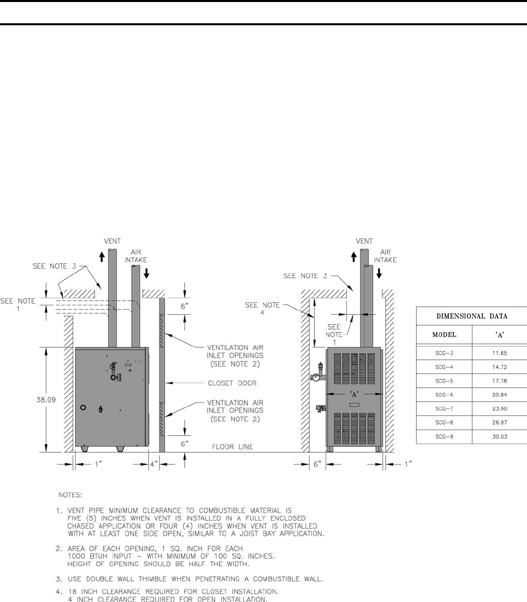
Figure 1: Minimum Clearances to Combustibles
I. Pre-Installation ............................... 6
II. Unpack Boiler ................................ 7
III. Venting/Air Intake Piping .............. 8
IV. Water Piping and Trim ................. 45
V. Gas Piping .................................... 50
VI. Electrical ....................................... 53
VII. Modular Installation .................... 62
VIII. System Start-up ............................ 64
IX. Service .......................................... 68
X. Repair Parts .................................. 74
5
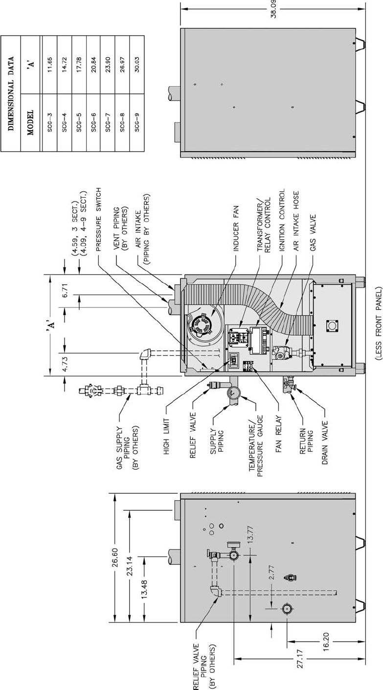
Figure 2: Dimensions
6
GNINRAW
snoitcurtsniesehtwolloftonoduoyfI
tluseryamnoisolpxeroerifa,yltcaxe
lanosreproegamadytreporpgnisuac
.yru
jni
REGNAD
rehtoroenilosagerehwreliobllatsnitonoD
fosecruosro,sdiuqilrosropavelbammalf
,srenaelc,sehcaelb.e.i(snob
racordyh
cirbaf,srevomertniap,syarps,slacimehc
.derotsrodesuera).cte,srenetfos
ECITON
,reliobehtfotnetnocretawwolehtoteuD
ehtotdragerhtiwreliobehtfognizis-sim
evissecxenitluserlliwdaolmetsysgnitaeh
tnenopmocdetareleccadnagnilcycreliob
tnarrawTONSEODmahnruB.eruliaf
reliobdezis-simybdesuacserul
iaf
otreliobehtezisrevoTONOD.snoitacilppa
snoitallatsnireliobraludoM.metsyseht
reliobfodoohilekilehtecuderyltaerg
.gnizisrevo
A. Installation must conform to the requirements of the
authority having jurisdiction. In the absence of such
requirements, installation must conform to the National
Fuel Gas Code, NFPA 54/ANSI Z223.1, and/or CAN/
CGA B149 Installation Codes.
B. Appliance is design certifi ed for installation on
combustible fl ooring. Do not install boiler on
carpeting.
C. Provide clearance between boiler jacket and
combustible material in accordance with local fi re
ordinance. Refer to Figure 1 for minimum listed
clearance from combustible material. Recommended
service clearance is 24 inches from left side, right
side and front. Service clearances may be reduced to
minimum clearances to combustible materials.
D. Install on level fl oor. For basement installation provide
solid base such as concrete, if fl oor is not level or if
water may be encountered on fl oor around boiler. Floor
must be able to support weight of boiler, water and all
additional system components.
E. Protect gas ignition system components from water
(dripping, spraying, rain, etc.) during boiler operation
and service (circulator replacement, condensate trap,
control replacement, etc.).
I. Pre-Installation
F. Provide combustion and ventilation air in accordance
with applicable provisions of local building codes,
or: USA - National Fuel Gas Code, NFPA 54/ANSI
Z223.1, Air for Combustion and Ventilation;
Canada - Natural Gas Installation Code, CAN/
CGA-B149.1, or Propane Installation Code, CAN/
CGA-B149.2, Venting Systems and Air Supply for
Appliances.
GNINRAW
rianoitalitnevdnanoitsubmocetauqedA
reporperussaotdedivorpebtsum
.noitsubmoc
The following guideline is based on the National Fuel Gas
Code, NFPA 54/ANSI Z223.1.
1. Determine volume of space (boiler room). Rooms
communicating directly with space (through
openings not furnished with doors) are considered
part of space.
Volume [ft³] = Length [ft] x Width [ft] x Height [ft]
2. Determine Total Input of all appliances in space.
Round result to nearest 1,000 Btu per hour (Btuh).
3. Determine type of space. Divide Volume by Total
Input.
a. If result is greater than or equal to 50 ft³ per
1,000 Btuh, space is considered an unconfi ned
space.
b. If result is less than 50 ft³ per 1,000 Btuh, space
is considered a confi ned space.
4. Determine building type. A building of unusually
tight construction has the following characteristics:
a. Walls and ceiling exposed to outside atmosphere
have a continuous water vapor retarder with a
rating of 1 perm or less with openings gasketed
and sealed, and;
b. Weather-stripping has been added on openable
windows and doors, and;
c. Caulking or sealants applied in joints around
window and door frames, between sill plates and
fl oors, between wall-ceiling joints, between wall
panels, at plumbing and electrical penetrations,
and at other openings.
5. For boiler located in an unconfi ned space in a
building of other than unusually tight construction,
adequate combustion and ventilation air is normally
provided by fresh air infi ltration through cracks
around windows and doors.

7
c. Horizontal ducts. Minimum free area of one (1)
square inch per 2,000 Btu per hour input of all
equipment in space. Duct cross-sectional area
shall be same as opening free area.
Alternate method for boiler located within
confi ned space. Use indoor air if two permanent
openings communicate directly with additional
space(s) of suffi cient volume such that combined
volume of all spaces meet criteria for unconfi ned
space. Size each opening for minimum free area
of one (1) square inch per 1,000 Btu per hour
input of all equipment in spaces, but not less than
100 square inches.
7. Combustion Air/Ventilation Duct Louvers and
Grilles. Equip outside openings with louvers to
prevent entrance of rain and snow, and screens to
prevent entrance of insects and rodents. Louvers and
grilles must be fi xed in open position or interlocked
with equipment to open automatically before burner
operation. Screens must not be smaller than ¼ inch
mesh.
Consider the blocking effect of louvers, grilles and
screens when calculating the opening size to provide
the required free area. If free area of louver or grille
is not known, assume wood louvers have 20-25
percent free area and metal louvers and grilles have
60-75 percent free area.
II. Unpack Boiler
NOITUAC
reliobpmubtonoD.reliobpordtonoD
.roolftsniagatekcaj
A. Move boiler to approximate installed position.
B. Remove all crate fasteners.
C. Lift and remove outside container. Save two of the
wooden slats from the container sleeve for use in Steps
E and F.
D. Remove all boiler hold-down fasteners.
GNINRAW
ebdluohsreliobsihtfonoitallatsnI
delliksdnadeniartybylnonekatrednu
.ycnegaecivresdeifilauqamorflennosre
p
E. Tilt the boiler to its front side or back side and slide a
wooden slat under the three raised feet.
F. Tilt the boiler in the opposite direction and slide
another wooden slat under the three raised feet.
G. Slide the boiler left or right off the skid using the two
wooden slats as runners.
H. Move boiler to its permanent location.
NOITUAC
nanireliobsihtgnitarepodiova,)riAroodnI-noitceSgnitneVees(noitsubmocrofriaroodnignisufI
sireliobfI.tneserpera.cte,tsudllawyrd,srebifnoitalusniesool,tsudwaserehwtnemnorivne
yliaddetcepsnidnadenaelcebtsumstropdnaroiretnirenrubeht,snoitidnocesehtrednudetarepo
.noitareporeporperusniot
ECITON
delaes(tnevtceridhtiwdetareposrelioB
gnideenmorftpmexeera)noitsubmoc
ehtmorfrianoitsubmocrofsnoisivorp
d
ellatsnisignipipekatniriadedivorp,moor
sihtnisnoitcurtsniehtdnaedocrep
.launam
6. For boiler located within unconfi ned space in building
of unusually tight construction or within confi ned
space, provide outdoor air through two permanent
openings which communicate directly or by duct
with the outdoors or spaces (crawl or attic) freely
communicating with the outdoors. Locate one opening
within twelve (12) inches of top of space. Locate
remaining opening within twelve (12) inches of bottom
of space. Minimum dimension of air opening is three
(3) inches. Size each opening per following:
a. Direct communication with outdoors. Minimum
free area of one (1) square inch per 4,000 Btu per
hour input of all equipment in space.
b. Vertical ducts. Minimum free area of one (1)
square inch per 4,000 Btu per hour input of all
equipment in space. Duct cross-sectional area
shall be same as opening free area.
8
III. Venting / Air Intake Piping
Table 1: Air Intake / Vent System Options
GNINRAW
rocillatemnon,leetssselniats613epyTro403epyT,dezinavlaghtiwreliobsihtesutonoD
C4-92LAnonrehtoyna
®
.smetsystnevdesab
.ecnailppasihthtiwdoohtfardrorepmadcirtemorabaesutonoD
.reliobsihthtiwsrepmadtnevesut
onoD
,noitaroiretedtneverpoT.noitanimretdnuorasecafrusnomrofyamecidnaerutsioM
.).cte,detniap,delaes(ria
perdoogniebdluohssecafrus
eraerehtosdellatsniebtsumdnanoitarepoefasrofriahserfsdeenecnailppasihT
.riano
italitnevdnanoitsubmocetauqedarofsnoisivorp
.epipekatniriafoezisecudertonoD
-erPehtnideniatnocsnoitcirt
sernoitcurtsnirianoitsubmocwollofdnadnatsrednu,daeR
.launamsihtfosnoitcurtsninoitallatsnI
fosecruosro,s
diuqilrosropavelbammalfrehtoroenilosagerehwecnailppaetarepotonoD
,srenetfoscirbaf,srevomertniap,syarps
,slacimehc,srenaelc,sehcaelb.e.i(snobracordyh
.riaehtnitneserpro/dnaderots,desuera).cte
ehtotnidetneveb
nacecnailpparehtoon,yenmihchguorhtepiptnevgnillatsninehW
.yenmihc
.4elbaTotrefeR.shtgnelekatniria/tnevm
umixamdeecxetonoD
noitpOnoitpircseD
lanoitiddA
tiKtneV
deriuqeR
traP
rebmuN
noitallatsnI
dnagniwarD
noitacificepS
)noitceSeeS(
etarapeS.1
latnoziroH
tnevehthtobhtiw)noitsubmocdelaes(tneVtceriD
yllatnozirohgnitanimretepipekatniriadnaepip
rofsnoitarteneplaudividnihtiw)llawedisahguorht(
.slanimretdnagnipipekatniriadnatneveht
oN eeS
2elbaT .D
etarapeS.2
lacitreV
tnevehthtobhtiw)noitsubmocdelaes(tneVtceriD
yllacitrevgnitanimretepipekatniriadnae
pip
rofsnoitarteneplaudividnihtiw)foorehthguorht(
.slanimretdnagnipipekatniriadnatneveht
oN eeS
2elbaT .E
no
itanibmoC.3
latnoziroH
epiptnevehthtiw)noitsubmocdelaes(tneVtceriD
lanimretnommocatagniniojepipekatniriadna
pullawedisahguorht(yllatnozirohgnitanimretdna
.noitartenepenoylnohtiw)kciht"51ot
seY noitceS6-3
)21060
116( .F
noitanibmoC.4
lacitreV
epiptnevehthtiw)noitsubmocdelaes(tneVtceriD
lanimretnommocatagniniojepipeka
tniriadna
htiw)foorehthguorht(yllacitrevgnitanimretdna
.noitartenepenoylno
seY
noitceS4-3
)10-222001(
noitc
eS6-5
)10-322001(
.G
riAroodnI.5 dedivorpsinoitsubmocrofdesuriA-tneVrewoP
.gnidliubehtnihtiwmorf oN2elbaTeeS.
H
lanoitpO.6
etarapeS
latnoziroH
tnevehthtobhtiw)noitsubmocdelaes(tneVtceriD
yllatnozirohgnitanimretepipek
atniriadnaepip
rofsnoitarteneplaudividnihtiw)llawedisahguorht(
.slanimretdnagnipipekatniriadnatneveht
oN2
elbaTeeS.I
9
Table 3: Burnham Vent System and Air Intake System Components
Table 2: Vent System Components Included with Boiler
stnenopmoCmetsyStneVrebmuNtraP
"3lanimreTtneVdeteksaG
)7-GCSurht3-GCS(latnoziroH 1070118
"4lanimreTtneVdeteksaG
)9GCS&8-GCS(latnoziroH 20
70118
"3-ekatnIriAcsiD
)4-GCS&3-GCS( 5406116
"4-ekatnIriAcsiD
)6-GCS&5-GCS( 9406116
"5-ekatnIriA
)9-GCSurht7-GCS( 3606116
Table 4: Vent/Air Intake Length
metsyStneV
tnenopmoC
traP
rebmuN
tnelaviuqE
epiPfoteeF
tF1xepiP.aiD"3U6926118 1
tF1xepiP.aiD"410-671001
tF3xepiP.aiD"3U8926118 3
tF3xepiP.aiD"410-771001
tF5xepiP.aiD"
3U0036118 5
tF5xepiP.aiD"410-871001
elbatsujdAxepiP.aiD"3U9136118 otlauqE**
htgneLdellatsnI
)46.1ot60.1(
elbats
ujdAxepiP.aiD"410-971001
woblE°09.aiD"3U4926118 5
woblE°09.aiD"410-081001
woblE°54.aiD"3U2926118 5
woblE°54.aiD
"410-181001
eeTniarDlatnoziroH.aiD"3U2036618 ½7
eeTniarDlatnoziroH.aiD"410-281001
eeTniarDlacitreV.aiD"3U4036
118 ½7
eeTniarDlacitreV.aiD"410-381001
elbmihTllaWelgniS"36116118 ---
elbmihTllaWelgniS"410-481001
elbmihTllaW
elbuoD"35116118 ---
elbmihTllaWelbuoD"410-581001
metsySekatnI
stnenopmoC
)srehtOybstraP(
tnelaviuqE
*epiPfoteeF
tF1xepiPDI"5ro,"4,"31
tF2xepiPDI"5ro,"4,"32
tF4xepiPDI"5ro,"4,"34
tF5xepiPDI"5ro,"4,"35
woblE°09"4ro,"35
woblE°
54"4ro,"35
woblE°09"56
woblE°54"56
nodesaBepiPfoteeFtnelaviuqE*
ngiseDepiPekomS"4dradnatS
ledoM
epiPekatnIriA"3
).tF.viuqE(
epiPekatnIriA"4
).tF.viuqE(
epiPekatnIriA"5
).tF.viuqE(
epiPtneV"3
).tF.viu
qE(
epiPtneV"4
).tF.viuqE(
.niM.xaM.niM.xaM.niM.xaM.niM.xaM.niM.xaM
4-GCS&3-GCS805----------------805--------
6-GCS&5-GCS--------805--------805--------
7-GCS----------------805805--------
9-GCS&8-GCS-----
-----------804--------804
10
A. Vent Guidelines Due to Removal of an Existing
Boiler
For installations not involving the replacement of an
existing boiler, proceed to Step B.
When an existing boiler is removed from a common
venting system, the common venting system is likely
to be too large for proper venting of the remaining
appliances. At the time of removal of an existing
boiler, the following steps shall be followed with each
appliance remaining connected to the common venting
system placed in operation, while the other appliances
remaining connected to the common venting system are
not in operation:
1. Seal any unused openings in the common venting
system.
2. Visually inspect the venting system for proper
size and horizontal pitch and determine there is no
blockage or restriction, leakage, corrosion, and other
defi ciencies which could cause an unsafe condition.
3. Insofar as is practical, close all building doors and
windows and all doors between the space in which
the appliances remaining connected to the common
venting system are located and other spaces of the
building. Turn on clothes dryers and any appliance
not connected to the common venting system.
Turn on any exhaust fans, such as range-hoods and
bathroom exhausts, so they will operate at maxi mum
speed. Do not operate a summer exhaust fan. Close
fi replace dampers.
4. Place in operation the appliance being inspected.
Follow the Lighting (or Operating) Instructions.
Adjust thermo stat so appliance will operate
continuously.
5. Test for spillage at the draft hood relief opening
after fi ve (5) minutes of main burner operation. Use
the fl ame of a match or candle, or smoke from a
cigarette, cigar or pipe.
6. After it has been determined that each appliance
remain ing connected to the common venting system
properly vents when tested as outlined above, return
doors, win dows, exhaust fans, fi replace dampers and
any other gas burning appliance to their previous
conditions of use.
7. Any improper operation of the common venting
system should be corrected so the installation
conforms with the National Fuel Gas Code, NFPA
54/ANSI Z223.1. When resizing any portion of the
common venting system, the common venting
system should be resized to approach the minimum
size as determined using the appropriate tables in
Part II in the National Fuel Gas Code, NFPA 54/
ANSI Z223.1.
B. General Guidelines
1. Vent system installation must be in accordance
with National Fuel Gas Code, NFPA 54/ANSI
Z221.3 or applicable provisions of local building
codes. Contact local building or fi re offi cials about
restrictions and installation inspection in your area.
2. The SCG is designed to be installed as either
a Direct Vent boiler or Power Vent boiler. In
the Direct Vent confi guration all of the air for
combustion is supplied directly to the burner
enclosure from outdoors and fl ue gases are vented
directly outdoors (through wall or roof). In the
Power Vent confi guration, room air provides air
for combustion and ventilation. Flue gases are still
vented directly outdoors (through wall or roof).
Note: Venting requirements change if indoor air is
used.
3. Refer to the appropriate drawings in this section of
this manual to determine the proper confi guration of
venting system. See Table 1.
4. This appliance requires a Special Gas Vent. The
product is designed to use Burnham supplied
AL 29-4C® Stainless Steel vent system components.
The following manufacturers offer similar
AL 29-4C® components and are approved for use
with this product. Heat-Fab Inc. - Saf-T-Vent, Flex-L
International Inc. - Star-34, Z-Flex U. S., Inc. -
Z-Vent, and Protech Systems , Inc.- FasNSeal™ or
equivalent. The use of these alternate manufacturer’s
venting systems will require adapters to connect
to the Burnham supplied vent connector and vent
terminal. These adapters are not supplied with this
unit and should be obtained from the supplier of
the alternate manufacturer’s venting system. See
Table 3 for complete list of Burnham Vent System
Components.
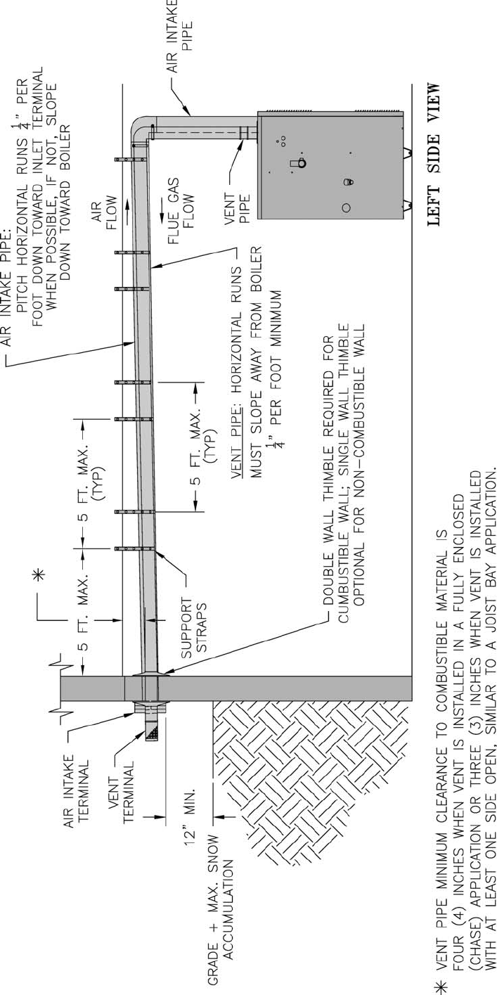
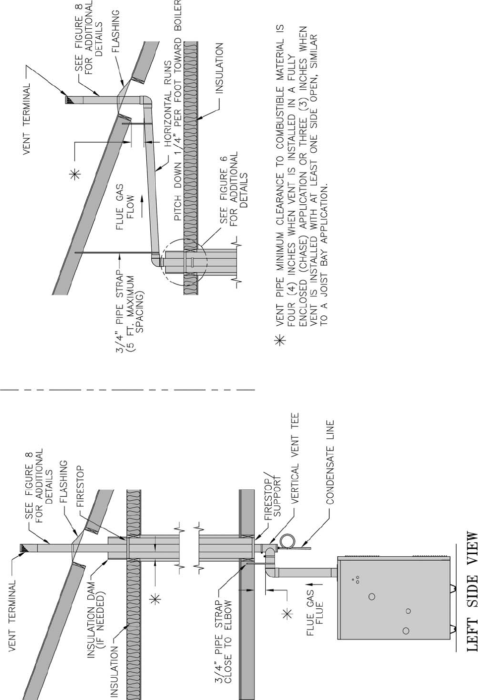
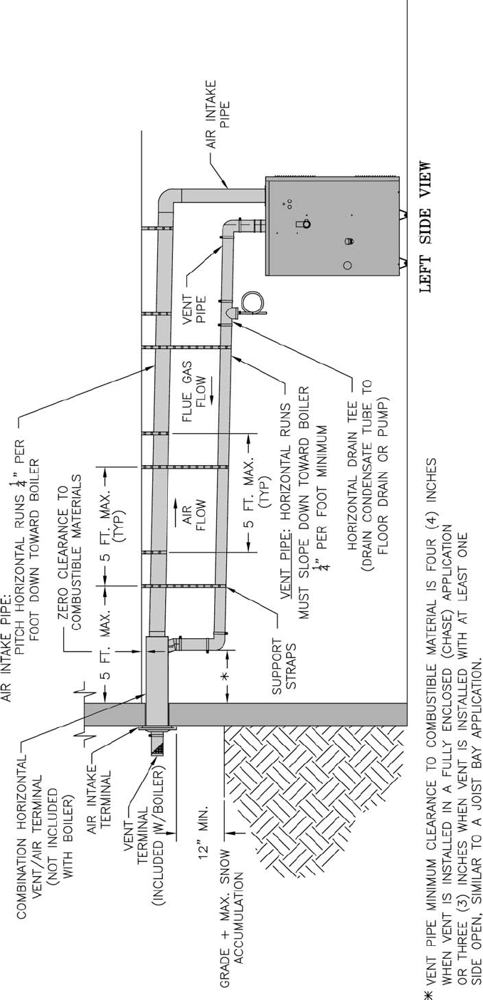
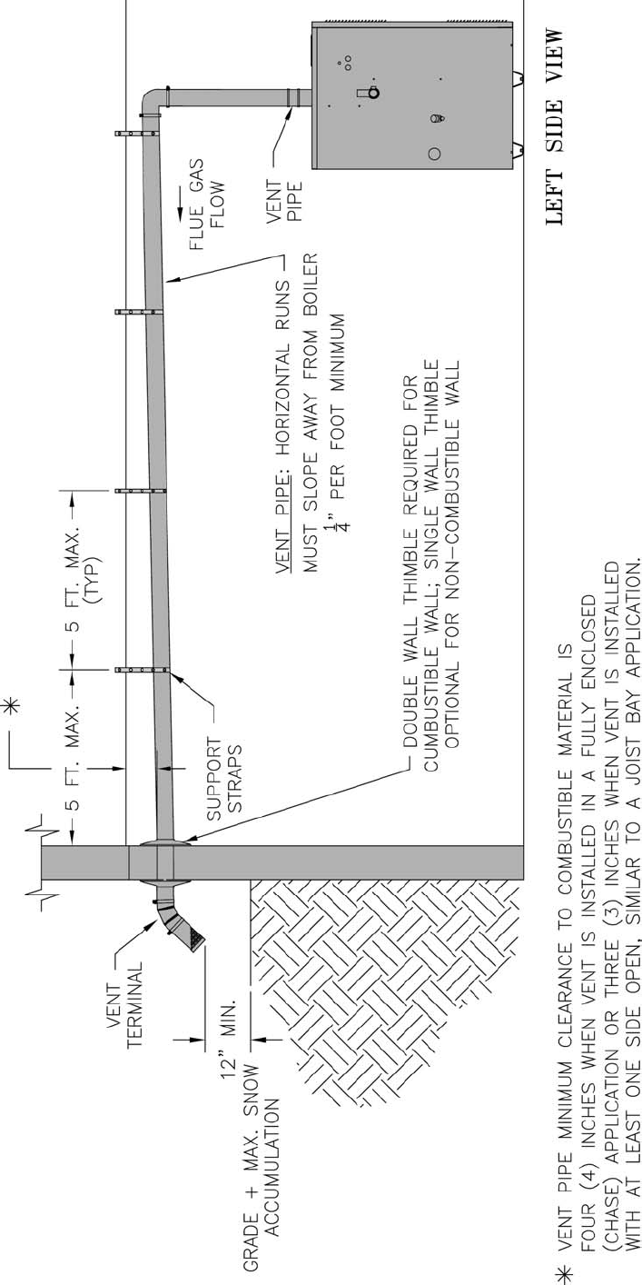
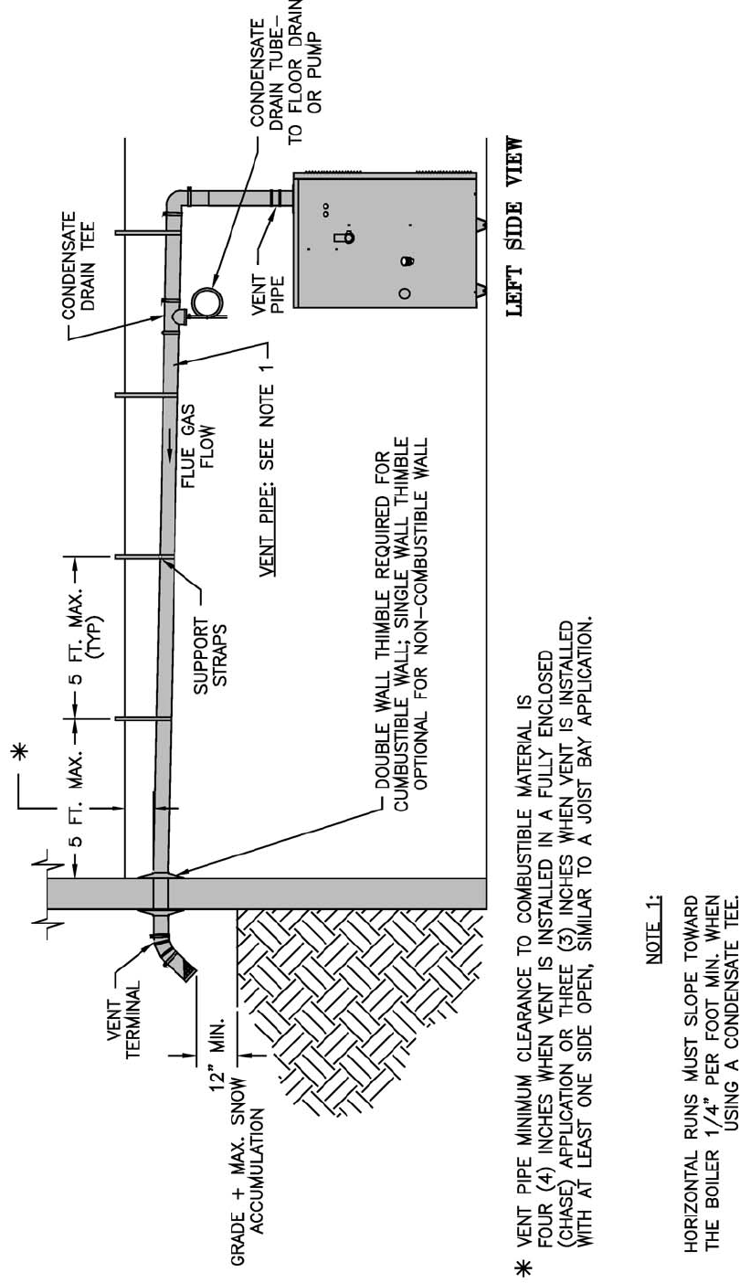
5. Horizontal vent pipe must maintain a minimum ¼
inch per foot slope down towards boiler.
6. Use noncombustible ¾ inch pipe strap to support
horizontal runs and maintain vent location and
slope while preventing sags in pipe. Do not restrict
thermal expansion or movement of vent system.
Maximum support spacing is fi ve (5) feet. Do not
penetrate any part of the vent system with fasteners.
7. Vent length restrictions are based on equivalent
length of vent/air pipe (total length of straight
pipe plus equivalent length of fi ttings). Maximum
vent/air lengths are listed in Table 4. Do not exceed
maximum vent/air intake lengths. Table 3 lists
equivalent lengths for fi ttings. Do not include vent/
air terminals in equivalent feet calculations.
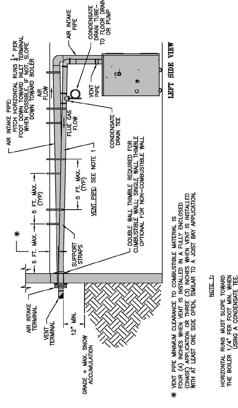
8. Provide and maintain vent pipe minimum clearances
to combustible materials. Vent pipe minimum
clearance to combustible material is four (4) inches
when vent is installed in a fully enclosed (chase)
application or three (3) inches when vent is installed
11
with at least one side open, similar to a joist bay
application. Use double wall thimble [Burnham
Part No. 8116115 (3”), 100185-01 (4”)] when
penetrating a combustible wall.
9. Do not install venting system components on
the exterior of the building except as specifi cally
required by these instructions. The vent termination
location is restricted as follows:
a. Minimum twelve (12) inches above grade plus
normally expected snow accumulation level, or
seven (7) feet above grade if located adjacent
to public walkway. Do not install over public
walkway where local experience indicates
appliance fl ue gas vapor or condensate creates a
nuisance or hazard.
b. Minimum three (3) feet above any forced air
inlet located within ten (10) feet.
c. Direct Vent - Minimum one (1) foot below, one
(1) foot horizontally from, or one (1) foot above
any door, window, or gravity air inlet.
Power Vent - Minimum four (4) feet below, four
(4) feet horizontally from, or four (4) feet above
any door, window, or gravity air inlet.
d. Minimum four (4) feet horizontally from electric
meters, gas meters, regulators, and relief valves.
This distance may be reduced if equipment is
protected from damage due to condensation or
vapor by enclosure, overhangs, etc.
e. Minimum twelve (12) inches from overhang or
corner of building.
10. Enclose vent passing through occupied or
unoccupied spaces above the boiler with material
having a fi re resistance rating of at least equal to the
rating of the adjoining fl oor or ceiling. Maintain
minimum clearances to combustible materials. See
Figure 1.
Note: For one or two family dwellings, fi re
resistance rating requirement may not need to be
met, but is recommended.
11. Plan venting system to avoid possible contact with
plumbing or electrical wires. Start at vent connector
on top of boiler and work towards vent terminal.
12. Once a vent pipe manufacturer and system is chosen
never mix and match vent systems.
13. If a non-standard length pipe is required:
Gasketed Vent System: The use of the adjustable
length pipe (P/N 8116319U) is recommended to
complete a non-standard pipe length. This pipe
requires a minimum installed length of 12¾ inch
and can adjust across a 7 inch gap up to a maximum
of 19¾ inch long. (Note for the adjustable pipe
the installed length should be measured from the
centerline of the bead on the male end of the fi rst
pipe to the end of the female pipe excluding the
locking band of the second pipe with a single
gasket.) Only in the event the adjustable length pipe
is not suffi cient a standard length pipe may be cut
using the procedure outlined below for the Gasket-
Less Vent System.
GNINRAW
fohtgneldellatsnimumixamdeecxereveN
.epiphtgnelelbatsujdarofsehcni¾91
.elbissopsiegakaelsageulffoksiR
ECITON
rodelifdnaepiphtiwerauqsebtsumtuC
ylluferaC.gniniojerofebhtoomsdednas
htiwdnahybepiptucfossendnuorerusn
e
VTRhtiwtniojlaeS.gnillatsnierofebsevolg
.launamsihtnideificeps
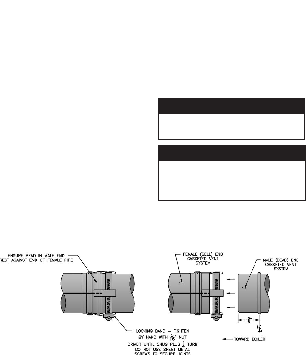
C. Install Vent Pipe, Burnham Gasketed Vent System.
1. Procedure for Joining Burnham Gasketed Vent Pipe
and Fittings. See Figure 3.
Figure 3: Burnham Gasketed Vent Joint Detail
12
a. Wipe the male end of each joint using an alcohol
pad to remove any dirt and grease.
b. Align weld seams in pipes and use a slight
twisting motion to FULLY insert male end into
female end of joint. Ensure bead in male end
of pipe is below locking band and rest against
the end of the female pipe. Verify the factory-
installed gasket is not dislodged or cut.
c. Tighten locking band by HAND with a 5/16”
nut driver until snug plus ¼ turn. DO NOT
SECURE JOINTS WITH SHEET METAL
SCREWS OR POP RIVETS. DO NOT
PUNCTURE THE VENT SYSTEM!
d. Once the installation is complete, operate
appliance and inspect all joints to ensure that fl ue
gases and/or liquid condensate will not escape.
D. Separate Horizontal Venting System. See Figures 4,
5A and 5B.
Vent Piping –
1. This boiler is supplied with components as standard
equipment for installation of the separate horizontal
venting system.
2. Do not exceed maximum vent/air intake lengths.
Refer to Table 4.
3. Recommended horizontal installation consists of
vent being sloped down ¼ inch per foot away from
boiler. See Figure 4.
4. Use appropriate designed thimbles when passing
through combustible walls (thimble use optional for
noncombustible walls). Insert thimble through wall
from outside. Secure outside fl ange to wall with
nails or screws, and seal ID, OD and vent holes with
sealant material. Install inside fl ange to inside wall,
secure with nails or screws, and seal with sealant
material.
5. For noncombustible wall application when thimble
is not used, size opening such that bell with locking
band attached cannot pass through.
6. Join vent terminal to vent pipe. See Figures 5A and
5B.
7. Insert vent pipe through thimble/opening from
outside and join to vent system. Apply sealant
between vent pipe and opening/thimble to provide
weathertight seal.
Air Intake piping - See Figures 4, 5A and 5B.
8. Locate air intake termination on the same wall as
the vent termination if possible, to prevent nuisance
boiler shutdowns. However, boiler may be installed
with vertical venting and sidewall combustion air
inlet or visa versa, if installation conditions do not
allow alternate arrangement.
9. Do not exceed air intake length. See Table 4.
10. Use single wall metal or PVC pipe.
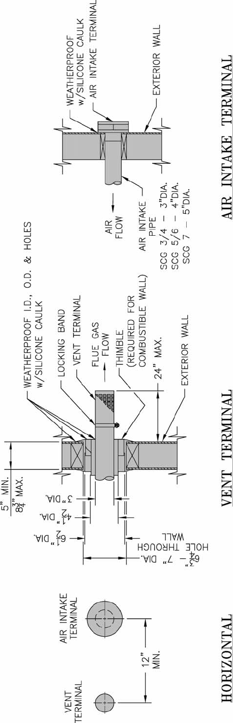
a. Air intake pipe diameter is based on boiler size.
SCG-3 & SCG-4 uses 3 inch diameter piping.
SCG-5 & SCG-6 uses 4 inch diameter piping.
SCG-7 thru SCG-9 uses 5 inch diameter piping.
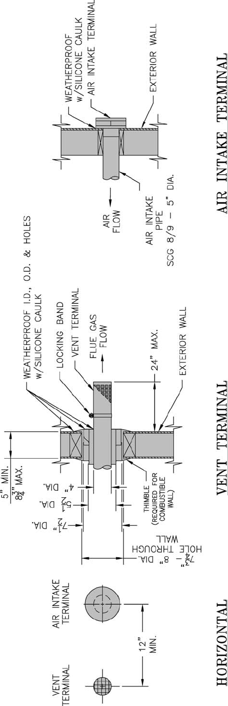
11. Air intake termination must be located:
Horizontal - At least twelve (12) inches above
grade plus the expected snow accumulation.
12. Start at collar on burner enclosure (inside boiler
jacket) and work towards the air intake terminal.
13. Maintain minimum of ¼ inch per foot slope on
horizontal runs. Slope towards air inlet terminal
when possible. If not, slope towards boiler.
14. The air intake pipe must be adequately supported
with straps or supports no less than fi ve (5) feet
apart on horizontal runs. The complete air intake
piping system must be rigid and able to withstand
minor impacts without collapse.
15. Inlet air pipe penetration:
Horizontal - Size wall penetration to allow easy
insertion of air inlet piping. Seal around pipe with
sealant to form weathertight exterior joint.
16. Seal all joints airtight, using silicone caulk or self-
adhesive aluminum tape.
17. Install Air Intake Terminal:
Horizontal - Remove four (4) screws from cover
plate and remove cover plate from terminal. Insert
intake piping into intake terminal collar. Secure
terminal to intake piping and seal joint with silicone
caulk or self-adhesive aluminum tape. Apply
continuous bead of silicone caulk around the back
of the intake terminal, approximately ¼ inch from
its edge. Push inlet terminal inward until terminal’s
back fl ange is against the wall surface. Secure the
terminal with noncorrosive fasteners (stainless steel,
brass or aluminum) to the wall. Reinstall the cover
plate with four (4) screws. Apply a bead of silicone
caulk to perimeter of intake terminal’s back fl ange
to provide a weathertight seal.
13
Figure 4: Recommended Separate Horizontal – Vent/Air Intake Installation
14
Figure 4B: Alternate Separate Horizontal – Vent/Air Intake Installation
15
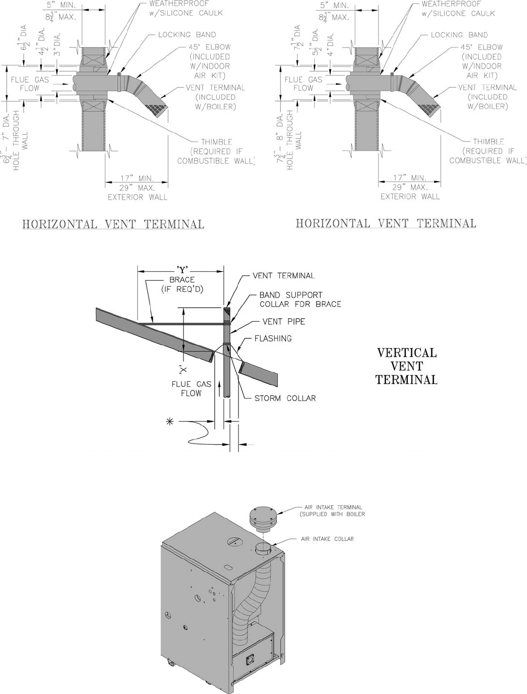
Figure 5A: Separate Horizontal – Vent/Air Intake Terminal Confi guration (SCG-3 thru 7)
16
Figure 5B: Separate Horizontal – Vent/Air Intake Terminal Confi guration (SCG-8 and 9)

17
Vertical Venting –
1. Do not exceed maximum vent lengths. Refer to
Table 4.
2. Installation of a vertical vent tee 8116304U is
required on all vertical vent applications. See
Figures 6 and 7. Attach vertical vent drain tee
directly to elbow or horizontal pipe from an elbow
immediately after vent connector.
3. Slope horizontal runs minimum ¼ inch per foot.
Slope towards vertical vent drain tee. Position weld
seams in vent pipes, in all horizontal runs, at the top
to avoid condensate from lying on the seams.
4. Install fi re stops where vent passes through fl oors,
ceilings or framed walls. The fi re stop must close
the opening between the vent pipe and the structure.
5. Whenever possible, install vent straight through
the roof. Refer to Figure 7 if offset is necessary.
Maintain minimum clearance to combustible
materials.
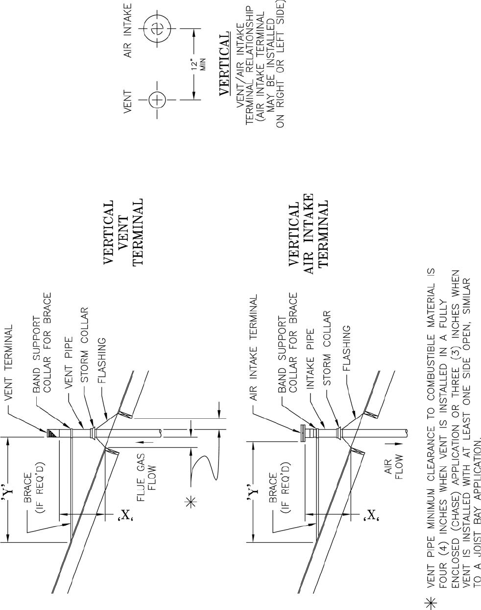
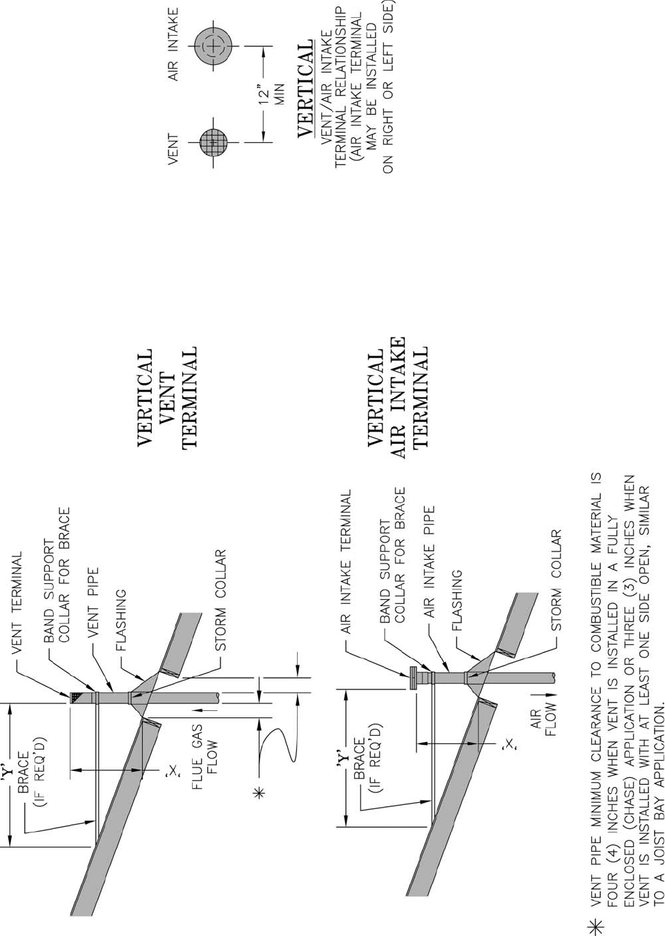
6. Install Vent Terminal.
a. Size roof opening to maintain minimum
clearance from combustible materials.
b. Extend vent pipe to maintain minimum vertical
and horizontal distance of twelve (12) inches
from roof surface. Allow additional vertical
distance for expected snow accumulation.
Provide brace as required. Refer to Figures 8A
and 8B.
ECITON
foorfoesuehtseriuqergnitnevlacitreV
tneverpotrallocmrotsadnagnihsalf
.erutcurtsehtgniretnemorferutsiom
c. Install storm collar on vent pipe immediately
above fl ashing. Apply Dow Corning Silastic 732
RTV Sealant between vent pipe and storm collar
to provide weathertight seal.
d. Attach vent terminal.
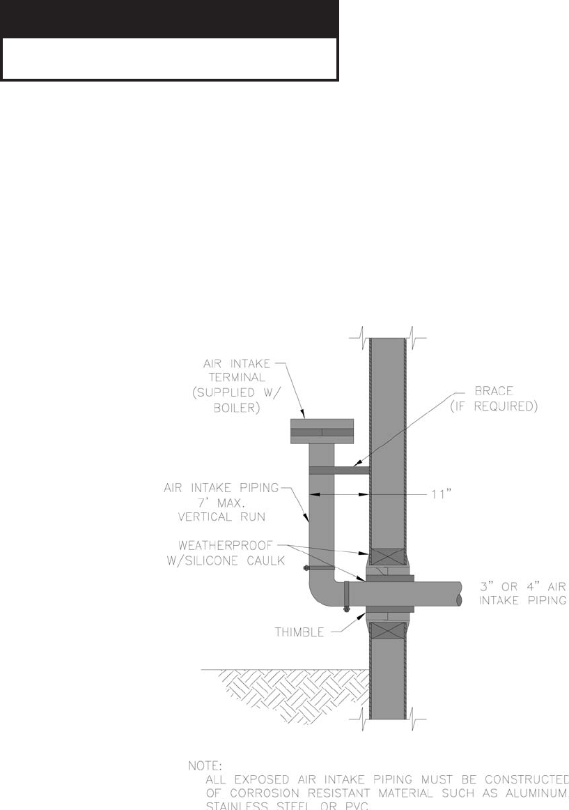
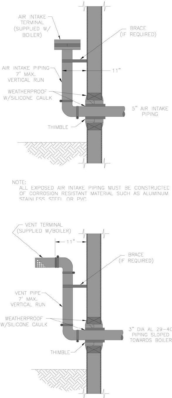
Vertical Air Intake Piping –
7. Do not exceed maximum air intake length. Refer to
Table 4.
8. Locate air intake termination on the same roof
location as the vent termination if possible, to
prevent nuisance boiler shutdowns. However, boiler
may be installed with vertical venting and sidewall
combustion air inlet or visa versa, if installation
conditions do not allow alternate arrangement.
9. Use single wall metal pipe or PVC and fi ttings
available at most heating distributors.
a. Air intake pipe diameter is based on boiler size.
SCG-3 & SCG-4 uses 3 inch diameter piping.
SCG-5 & SCG-6 uses 4 inch diameter piping.
SCG-7 thru SCG-9 uses 5 inch diameter piping.
10. Air intake termination must be located:
Vertical - At least twelve (12) inches above the roof
surface plus the expected snow accumulation.
11. Start at collar on burner enclosure (inside boiler
jacket) and work towards the air intake terminal.
12. Maintain minimum of ¼ inch per foot slope on
horizontal runs. Slope down towards boiler.
13. The air intake pipe must be adequately supported
with straps or supports no less than fi ve (5) feet
apart on horizontal runs. The complete air intake
piping system must be rigid and able to withstand
minor impacts without collapse.
14. Inlet air pipe penetration:
Vertical - Size roof opening to allow easy insertion
of inlet piping and allow proper installation of
fl ashing and storm collar.
a. Use appropriately designed vent fl ashing
when passing through roofs. Follow fl ashing
manufacturers’ instructions for installation
procedures. Flashing manufacturers are Air-
Jet, American Metal Products, Metal Fab, and
Simpson Dura-Vent.
b. Extend air intake pipe to maintain minimum
vertical and horizontal distance of twelve
(12) inches from roof surface. Allow
additional vertical distance for expected snow
accumulation. Provide brace as required. Refer
to Figures 8A and 8B.
c. Vertical air intake requires fl ashing and a storm
collar to prevent moisture from entering the
structure.
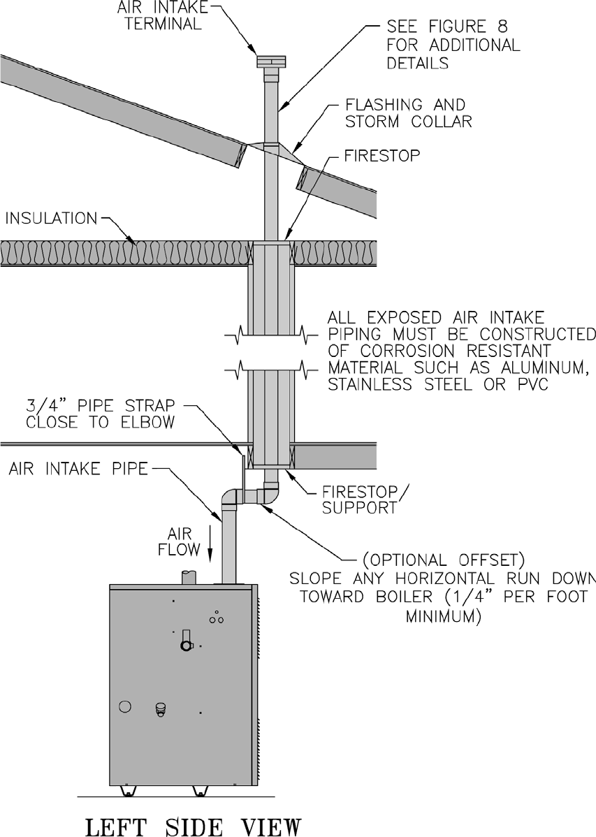
E. Separate Vertical Venting System - See Figures 6, 7, 8A, 8B and 9.
ECITON
foorfoesuehteriuqersnoitartenepfooR
htiwdeilppuston-rallocmrotsdnagnihsalf
.reliob
18
d. Install storm collar on air intake pipe
immediately above fl ashing. Apply Dow
Corning Silastic 732 RTV Sealant between
air intake pipe and storm collar to provide
weathertight seal.
e. All exposed air intake piping must be
constructed of corrosion resistant material such
as aluminum, stainless steel or PVC.
15. Seal all joints airtight, using silicone caulk or self-
adhesive aluminum tape.
16. Install Air Intake Terminal:
Vertical - Insert intake piping into intake terminal
collar. Secure terminal to intake piping and seal
joint with silicone caulk.
19
Figure 7: Attic OffsetFigure 6: Vertical Vent Installation
20
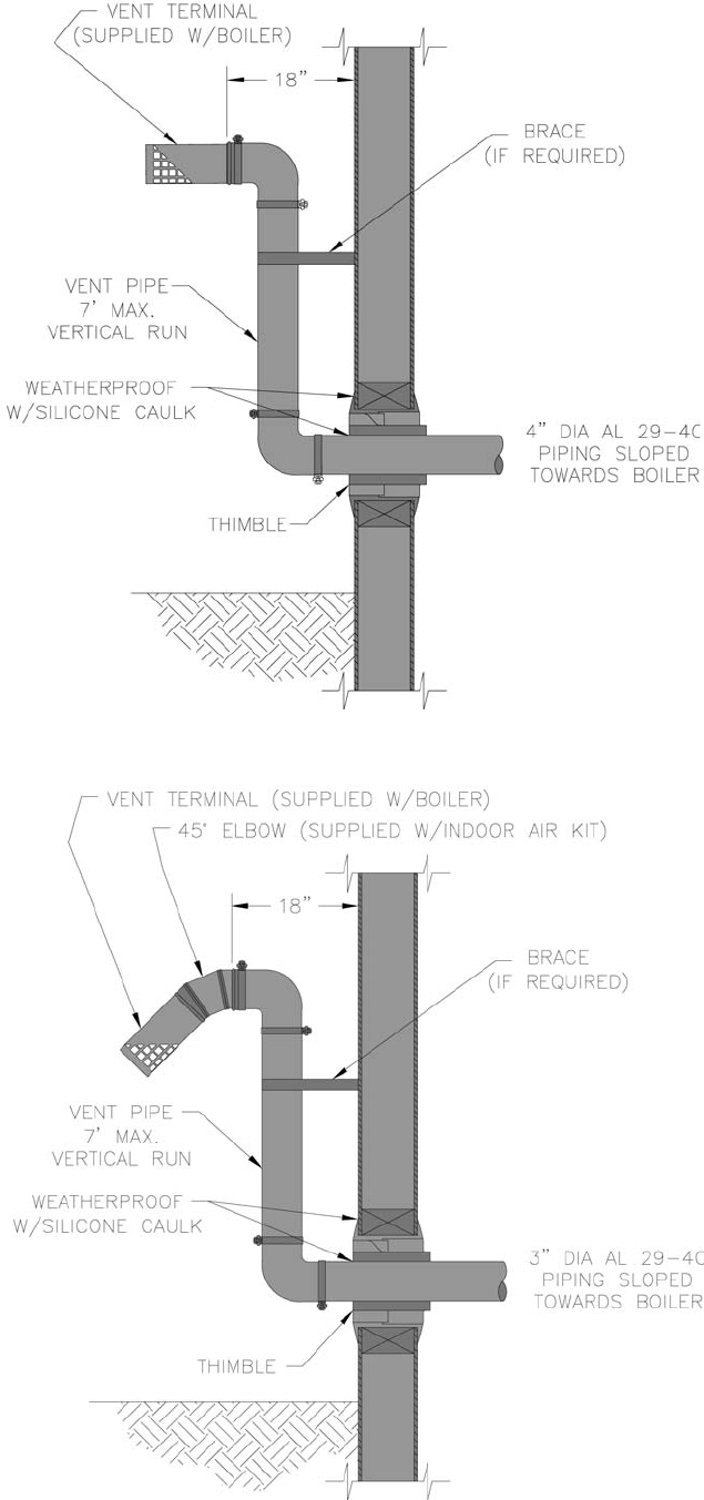
Figure 8A: Vertical Vent/Air Termination (3” Vent Terminal)
Extend Vent/Air Intake Piping to maintain minimum vertical (“X”) and minimum horizontal (“Y”) distance of twelve (12) inches from
roof surface. Allow additional vertical (“X”) distance for expected snow accumulation.
21
Figure 8B: Vertical Vent/Air Termination (4” Vent Terminal)
Extend Vent/Air Intake Piping to maintain minimum vertical (“X”) and minimum horizontal (“Y”) distance of twelve (12) inches from roof surface. Allow ad-
ditional vertical (“X”) distance for expected snow accumulation.
22
Figure 9: Vertical Air Intake Piping
23
F. Combination Horizontal Venting System –SCG-3 Through SCG-6 ONLY – See Figures 10 and 11.
ECITON
tonstnenopmocseriuqermetsystnevsihT
.reliobehthtiwdeilppus
1. Do not exceed maximum vent/air intake lengths.
Refer to Table 4.
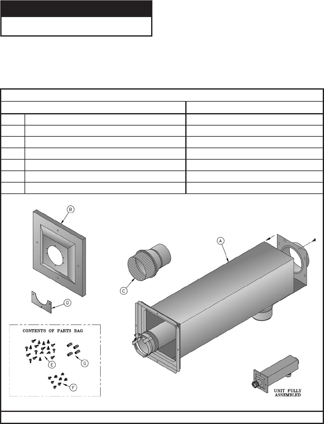
2. Install Combination Vent/Air Terminal. See Figure 11.
a. After determining the location with reference to Section B - General Venting Guidelines, cut a 6-1/8 inch square
opening in the wall for the air box sub-assembly which is 6 inch square.
b. Remove and save shipping screw from end panel with collar and vent pipe assembly. This will be reinstalled in a later
step.
21060116rebmuNtraPnotraCtneV)wolebsmetisedulcni(
noitpircseDrebmuNtraPtnenopmoC
A)gnol'2xerauqs"6(ylbmessA-buSxoBriA 11060116
B)erauqs"01(revoCllaWroiretxE 61060117
CrecudeRepiPtneV"3x"4 93
26118
D)2(revoCroiretxElaeS-etalP 71060117
E)91(wercSlateMteehSleetSsselniatS"½x8# 74006808
F)8(wercSenihcaMleetSsselniatS"¼x23-01# 24806808
G)4(recapSmunimulA"½x23-01# 71616808
STNENOPMOCMETSYSTNEVLATNOZIROHNOITANI
BMOC

24
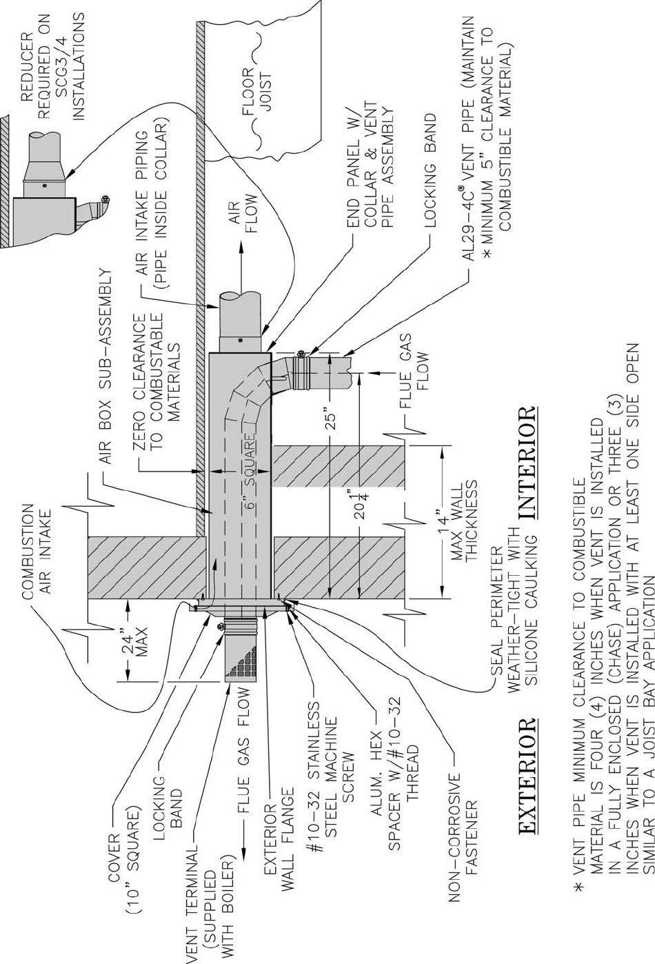
c. From exterior of building, insert air box sub-
assembly into square opening. Push air box
inward until wall fl ange is against wall, check
for level and mark the location of the four (4)
securing holes on the exterior wall. Remove air
box from wall.
d. Drill four (4) pilot holes, properly sized for the
non-corrosive fasteners (stainless steel, brass, or
aluminum) to be used to secure the wall fl ange to
the exterior wall. (Securing screws not supplied
with kit.)
e. Attach four (4) 1/2 inch long threaded aluminum
spacers to the outer fl anges of the exterior
wall fl ange with four (4) number 10 - 32 x 1/4
inch stainless steel machine screws provided.
(See Figure 11.)
f. Apply a 1/4 inch thick continuous bead of
silicone caulk to perimeter of exterior wall
fl ange’s back surface to provide a weathertight
seal.
g. Reinstall air box sub-assembly into opening in
exterior wall and secure to wall.
GNINRAW
.desuebtsumsrenetsafevisorroc-noN
h. Apply a bead of silicone caulk to perimeter of
wall fl ange, where the wall and fl ange join. Use
a tool or your fi nger and apply pressure while
smoothing caulking to provide a weathertight
seal.
i. From interior of building, insert end panel with
collar and vent pipe assembly into open end of
air box sub-assembly. (See Figure 11.)
j. Secure end panel to air box sub-assembly with
shipping screw and thirteen (13) number 8 sheet
metal screws provided.
k. From exterior of building, position 10 inch
square exterior wall cover over exterior wall
fl ange. Insert 3 inch diameter vent pipe into
center opening in terminal cover. Align four
(4) holes on cover with 1/2 inch long threaded
spacers on wall fl ange. Secure terminal cover
with four (4) number 10 - 32 x 1/4 inch stainless
steel machine screws provided.
l. Apply a bead of silicone caulk to perimeter of
plate-seal and around pipe. Secure plate-seal to
exterior cover with six (6) #8 stainless steel sheet
metal screws provided. Smooth caulk around
plate-seal and pipe to provide weathertight seal.
m. Install Vent Terminal supplied with boiler to vent
pipe penetrating through terminal cover. Join
terminal and pipe with locking band and seal
with RTV (see Figure 3).
3. Install Vent Piping. See Figure 10 and 11.
a. Start at vent connector on boiler and work
towards combination vent/air terminal.
b. Installation of a vertical vent tee 8116304U is
required on all vertical vent applications. See
Figures 12 and 13. Attach vertical vent drain
tee directly to elbow or horizontal pipe from an
elbow immediately after vent connector.
c. Slope horizontal runs minimum ¼ inch per foot.
Slope towards vertical vent drain tee. Position
weld seams in vent pipes, in all horizontal runs,
at the top to avoid condensate from lying on the
seams.
d. Use 3/4 inch pipe strap to support horizontal runs
and maintain vent location and slope. Maximum
support spacing is fi ve (5) feet.
e. Install vent piping to connect vent connector
on boiler and combination vent/air terminal.
Reference Section B - General Venting
Guidelines for proper procedure for joining pipe
and fi ttings.
f. Connect vent piping to combination vent/air
terminal. See Figure 10.
4. Install Air Intake Piping. See Figures 10 and 11.
a. Do not exceed air intake length. See Table 4.
b. Use single wall metal pipe or PVC and fi ttings
available at most heating distributors.
c. Air intake pipe diameter is based on boiler size.
SCG-3 & SCG-4 uses 3 inch diameter piping.
SCG-5 & SCG-6 uses 4 inch diameter piping.
SCG-7 thru SCG-9 uses 5 inch diameter piping.
d. Start at collar on burner enclosure (inside boiler
jacket) and work towards the combination vent/
air terminal.
e. Maintain minimum of 1/4 inch per foot slope on
horizontal runs. Slope down towards boiler.
f. The air intake pipe must be adequately supported
with straps or supports no less than fi ve (5)
feet apart on horizontal runs. The complete air
intake piping system must be rigid and able to
withstand minor impacts without collapse.
g. Connect Air Intake Piping to Combination Vent/
Air Terminal. See Figure 10.
NOTE: When installing 3 inch diameter air intake
piping for a SCG-3 or SCG-4 application, the use of
a 4 inch x 3 inch reducer will be required to connect
air intake piping to combination vent/air terminal.
(Reducer included with combination horizontal
venting kit).
h. Seal all joints airtight, using silicone caulk or
self-adhesive aluminum tape.
25
Figure 10: Combination Horizontal – Vent/Air Installation (SCG-3 thru 6)
26
Figure 11: Combination Horizontal – Vent/Air Terminal Installation (SCG-3 thru 6)
27
noitpircseD
rebmuNtraP
4-GCS&3-GCS6-GCS&5-GCS
rebmuNtraPnotraCtneV 10-22200110-322001
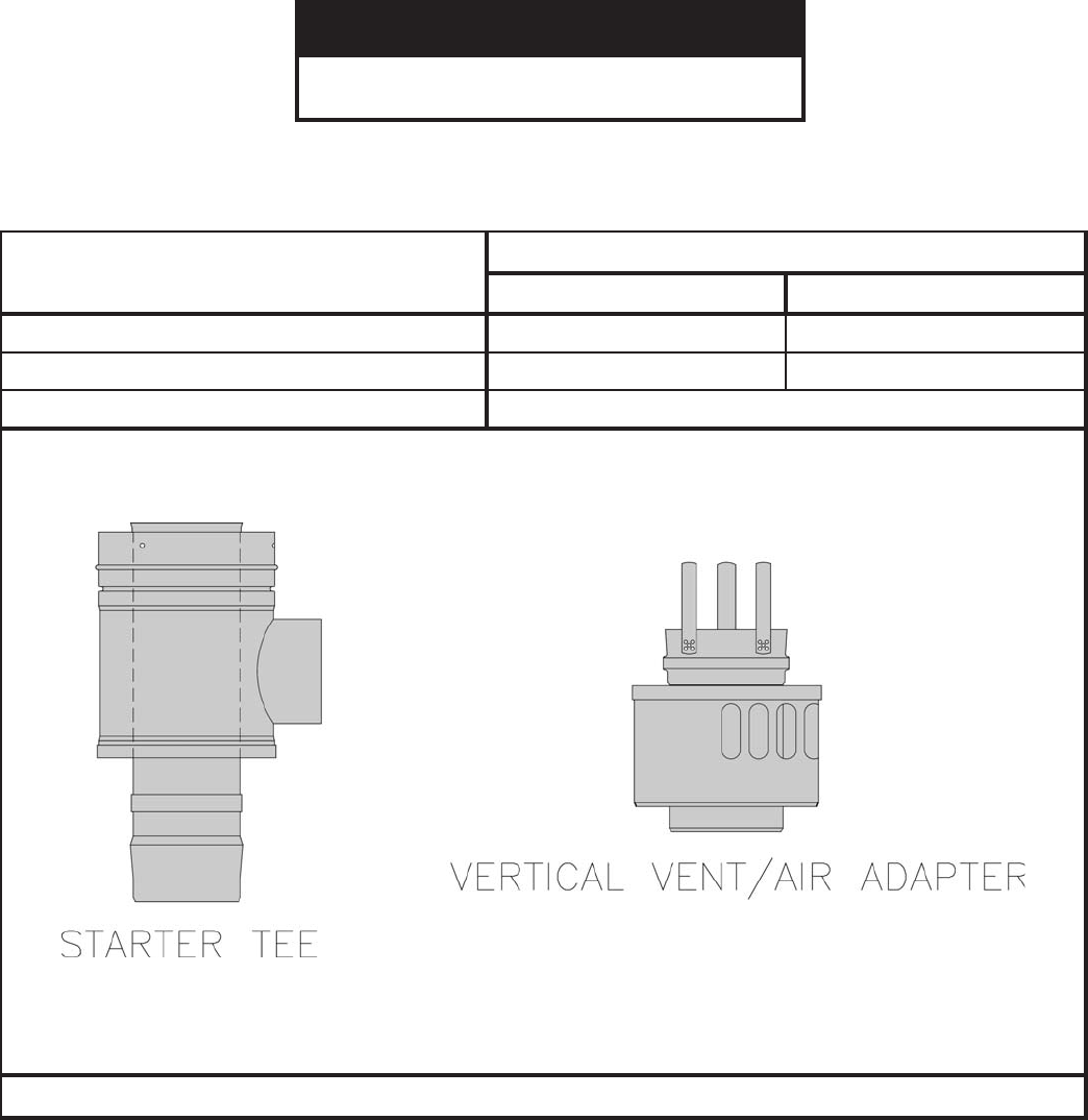
eeTretratS 10-42200110-522001
rotpadAriA/tneV 10-622001
STNENOPMOCMETSYSTNEVLACITREVNOITANIBMOC
G. Combination Vertical Venting System – SCG-3 Through SCG-6 ONLY – See Figures 12, 13 and 14.
ECITON
tonstnenopmocseriuqermetsystnevsihT
.reliobehthtiwdeilppus

28
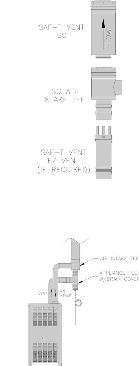
1. Saf-T Vent SC is an advanced concentric vent
system designed for zero clearance installation
in residential applications. The inner wall is
constructed from superferritic AL29-4C® stainless
steel. The outer wall is also constructed from
stainless steel, providing durability and a lasting
fi nish.
2. As a Special Gas Vent system: Saf-T Vent is
approved for use on ANSI Category I, II, III, and
IV Gas-Burning Appliances and certain Direct Vent
Appliances. Saf-T Vent SC is appropriate for use on
appliances that specify an AL29-4C venting system.
3. As a Sealed Combustion system: The unique
concentric design of Saf-T Vent SC also allows it
to function as a pipe-in-a-pipe vent. Products of
combustion are exhausted out through the inner wall
while combustion air is drawn in through the outer
wall. An appliance can be direct-vented with only
a single penetration through the building structure.
This application must be approved by the
Appliance Manufacturer.
Note: Saf-T Vent SC includes an integral seal and
does not require RTV sealant. However, sealant
may be necessary when connecting Saf-T Vent SC
components directly to certain appliance fl ue collars
and to the gasket-less Saf-T Vent GC and Saf-T Vent
CI vent systems.
For applications up to 550°F/288°C, approved
sealants include GE RTV 106 and Dow Corning
736.
For applications up to 300°F/149°C, approved
sealants include GE RTV 106 and Dow Corning
732.
4. Pre-Installation Considerations:
• Proper planning prior to installation is essential
as to avoid possible contact with concealed
plumbing or electrical wiring inside walls,
fl oors or ceilings as well as maintaining proper
clearances. Be sure to plan a suffi cient number
of supports for the entire system that will
maintain the required straight-line pitch and hold
the system in place. A continuous straight-line
pitch of at least ¼” (2°) to the foot on horizontal
runs must be maintained in order to properly rid
the system of the corrosive condensate.
5. General Installation Requirements:
• Saf-T Vent SC vent sections, or other Saf-T
Vent products, must be used throughout the
entire length of the system. Alternatives such
as galvanized pipe, PVC, nonmetallic pipe,
prefabricated chimney, fi eld-fabricated vents
or Type B vent sections must not be used. Do
not mix pipes, fi ttings, or joining methods from
different manufacturers.
• More than one appliance may not be
interconnected to any part of the venting system.
• Any penetrations of ceilings, fl oors or walls must
be properly fi re-stopped.
• Whenever gas-burning equipment is installed in
the same space where halogenated substances
may exist (refrigerants, solvents, bleaches,
salts, etc.), clean outside air must be utilized for
combustion.
• The vent system shall not be routed into,
through or within any other actively used vent or
chimney.
• Seal weather exposed joints of the outer jacket
with foil tape or an exterior grade silicone
sealant.
• Combustible Material is any material made of
or surfaced with wood, compressed paper, plant
fi bers, or other materials that are capable of
being ignited or burned. Such material shall be
considered combustible even though it is fl ame-
proofed, fi re-retardant, or plastered. (Source:
NPFPA54/ANSI Z223.1-1999.)
• Non-Combustible Material is any material that
is not capable of being ignited and burned, such
material consisting entirely of, or a combination
of, steel, iron, brick, tile, concrete, slate,
asbestos, glass and plaster. (Source: NPFPA54/
ANSI Z223.1-1999.)
retemaiD
otecnaraelC
elbitsubmoC
lairetaM
eulFmumixaM
)F°(.pmeTsaG noitatneirOerusolcnE
"4-"3
"0
055 ,lacitreV
stesffOoN elbitsubmocybdesolcneylluF
sedisllanolairetam
033
,latnoziroH
htiwlacitreV
ste
sffO
"1004
"0 004,nepoedis1tsaelta,desolcnenU
anolairetamelbitsubmoc
sedis3fomumixam
"1055
"0055ynAlairetamelbitsu
bmocnoN
Clearances to Combustibles:
29
• For a venting system that extends through
any zone above that on which the connected
appliance is located (except for one and two
family dwellings), the vent system shall be
enclosed with an enclosure having a fi re
resistance rating equal to or greater than that of
the fl oor or roof assemblies through which it
passes.
• Design any enclosure to permit inspection of the
system.
• Do not place any type of insulation in any
required clearance spaces surrounding the vent
system.
6. Vertical Installation Requirements:
a. Seal weather exposed joints of the outer jacket
with foil tape or an exterior grade silicone
sealant.
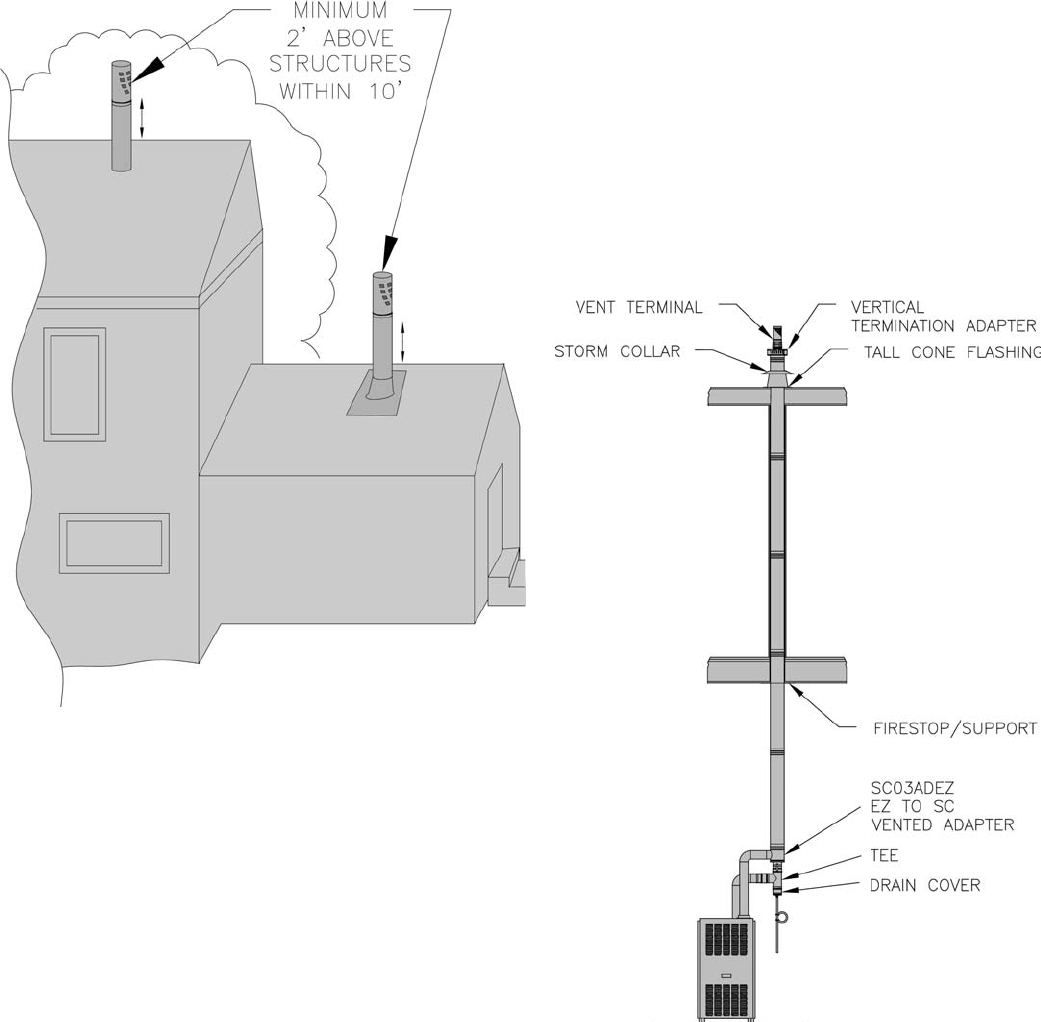
b. The vent system must terminate at least 3 feet
above the roof line and at least 2 feet higher than
any portion of the building within 10 feet.
c. When terminated at a height of more than 6 feet
the stack must be supported by a support bracing.
The vent should be supported every 10 feet.
d. The total continuous distance of the vent system
from the appliance fl ue collar to the termination
shall not exceed that specifi ed in the appliance
manufacturer’s installation instructions.
e. In cold climates do not install a condensate drain
on the exterior of the building. Doing so may
result in dangerous icy conditions on surfaces
near the drain and may cause damage to the vent
system and/or the building exterior.
f. Install supports every 10 feet vertically along the
vent pipe route. Vertical supports are required
after every transition to vertical and are required
after every offset elbow. When the vent is free
standing and penetrates a roof/ceiling another
means of support must be used at a second
location. Refer to the Vertical Supports section
in this manual.
30
7. Joint Assembly Instructions:
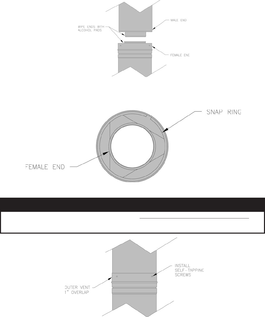
a. Before joining the sections or fi ttings together, use an alcohol pad to wipe the joint area of both ends of the inner
pipe. This will remove any foreign matter which may affect the integrity of the seal. Install the system with the
female ends (ends with the red seal) pointing away from the appliance. (Unless specifi ed differently by the appliance
manufacturer.)
b. Insert the male end of the inner pipe into the female end of the previous section. In extremely dry conditions it may be
helpful to moisten the seal with clean water prior to assembly. Push fi rmly until the outer jacket has made contact with
the snap ring located inside the female end of the previous section. When fully assembled the outer female end will
overlap the male end 1”.
c. Use the three (3) self-tapping screws provided to connect the outer vents. No pre-drilling is required.
NOITUAC
,llirdeuqrotelbairavagnisufI.nethgitrevotonoD
swercsllatsniotgnitteseuqrotwolaesu
sa,
retemaidregrala,gninethgitrevooteuddeppirtssemocebelohafI.selohehttuopirtsotton
.desuebnactevirtoptrohsro).xamgnol"½(wercs
31
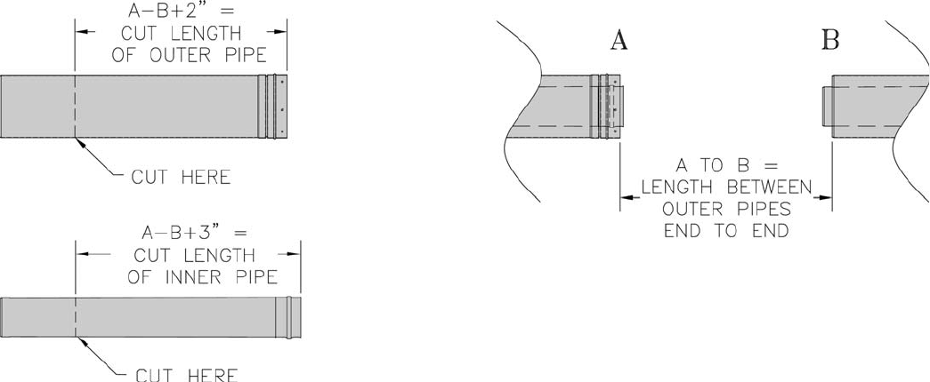
8. Straight Sections Cut To Length:
If a custom length of SC is necessary, a standard vent
section can be cut.
a. Measure the distance of the length needed, taking the
measurement from the end of one of the outer jackets
to the beginning of the other outer jacket on the
section to connect to, (A to B on diagram).
b. Select a section that is longer than the required
length.
c. It will be necessary to disassemble the vent prior to
cutting.
Stand the section on end with the holes up. Find the
end of snap ring and pry it out of its groove, being
careful not to damage the ends of the vent pipes.
Pull up on end of the snap ring and pull it out from
the end of the pipe. It may want to spiral out as it is
removed. After the snap ring is removed, the inner
vent pipe can be separated from the outer jacket.
d. Add 2” to the distance measured previously for the
cut length of the outer jacket. Mark a cut line on the
outer jacket on the male end (the end without holes in
it).
An effective way of marking is to run a length of tape
around the section, assuring a square cut.
e. Add 3” to the distance measured previously for the
cut length of the inner vent pipe. Mark a cut line on
the inner vent on the male end (the end without the
red seal).
The inner pipe is always cut 1” longer than the
outer pipe.
f. WEAR GLOVES, as cut ends are very sharp. Cut
the pipes with an abrasive cutoff saw, plasma cutter,
or compound snips. If using snips, start the cut at
the male end and follow a spiral path around the pipe
until the cutoff mark is reached. File off any burrs
or rough edges that develop in the cutting process
and clean off any dust or grit. If the cutting process
distorts the roundness of the pipes, carefully use your
thumbs to re-round the ends.
g. Reassemble the inner vent into the outer jacket and
reinstall the snap ring into the groove. Push the
inner vent into the outer jacket until the triangle on
the inner vent is seated fi rmly against the bead on
outer jacket. Start one end of the snap ring into the
groove of the outer pipe. Slowly turn and feet the
snap ring into the groove in a spiral motion, and
continue around the pipe until the snap ring is fully
inserted. Ensure that the triangle on the inner vent is
all the way down against the bead of the outer jacket
by pushing in fi rmly. Also ensure that the snap ring
is completely in the groove all the way around outer
jacket.
32
9. Air Intake Connections for Direct Vent and Sealed
Combustion Appliances*:
The Air Intake Tee may be used on approved direct vent
and sealed combustion appliances that have separate (non-
concentric) air intake and fl ue exhaust collars. The male end
of the tee connects to EZ Seal appliance adapters and the tee
takeoff/snout connects to the appliance air intake.
• Insert the male end of the Air Intake Tee into the female
end of the EZ Seal vent section or appliance adapter and
complete the ring and tab connection.
• Insert the male end of the next SC section into the female
end of the Air Intake Tee and secure as described elsewhere
in this manual.
• Connect the tee takeoff to the appliance combustion air inlet
using appropriate hose or pipe.
* Direct Vent Appliances are constructed and installed so that
all air for combustion is supplied directly from the outside
atmosphere. The passage for the combustion air is allowed
a small amount of leakage in the building environment. No
special installation considerations are required to use Saf-T
Vent SC on Direct Vent appliances unless specifi ed by the
appliance manufacturer. Sealed Combustion appliances are
similar to Direct Vent except the combustion air passage must
be sealed to prevent leakage within the building envelope.
When Saf-T Vent SC is used on approved Sealed Combustion
appliances the joints of the outer jacket must be sealed with
a foil tape (example: 3M 425), or approved silicone sealant
(example: Dow Corning 732).
10. Condensate Drains:
When An Internal Condensate Drain is NOT Part of the
Appliance:
• A Saf-T Vent SC In-Line Drain Section is strongly
recommended. Install this drain fi tting as close to the
appliance fl ue collar as possible.
• A condensate drain is required for every 30 feet of
horizontal vent and at/near the bottom of a vertical stack.
• Use the In-Line Drain Section for a straight horizontal or
vertical run. When used horizontally, rotate the fi tting so that
the drain tube is as vertical as possible.
• A Condensate Drain Tube Kit is available to direct the
condensate to an appropriate location, i.e. fl oor drain or
vented sanitary sewer connection. A trap loop must be
formed into the drain hose and must be a diameter that is
at least four (4) times the appliance’s rated stack pressure
in inches of water column or 3 inches, whichever is
greater. Secure the loop with a cable tie. Prior to fi nal
assembly the trap loop must be ‘primed’ by pouring a
small quantity of water into the drain hose. Inspect at least
annually to verify the trap is ‘primed’.
• Follow all local and national codes and regulations for the
draining of acidic condensate.
• In cold climates do not install a condensate drain on the
exterior of the building. Doing so may result in dangerous
icy conditions on surfaces near the drain and may cause
damage to the vent system and/or the building exterior.
33
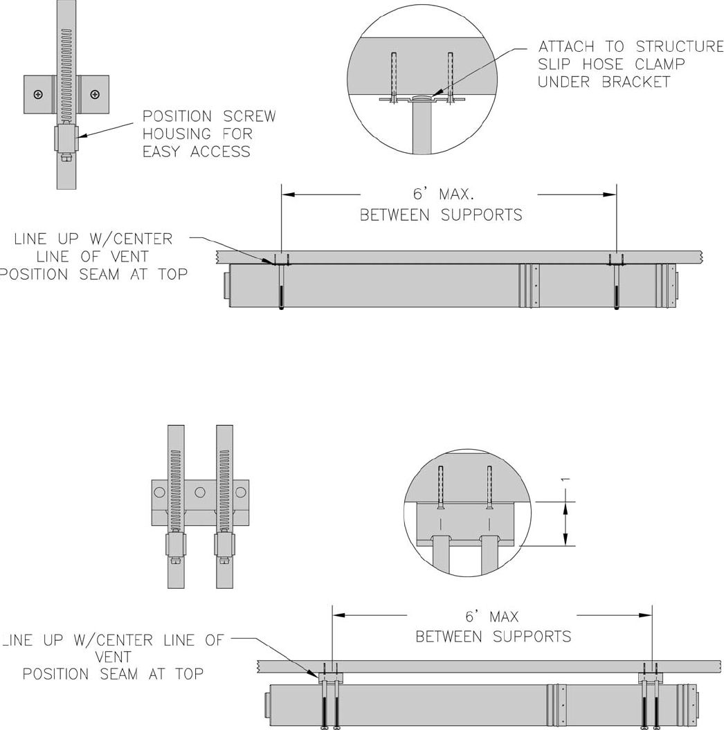
11. Horizontal Supports:
Saf-T Vent SC must have supports for every six (6) feet of horizontal run and after every transition from vertical to
horizontal. Support hangers by themselves do not maintain the necessary clearances to combustible materials; be sure to
consider clearances when planning the system.
The supports must be secured to solid material using at least #10 fasteners. Do not fasten supports to drywall sheathing
without using hollow wall anchors. The conduit supports must maintain the ¼” per foot pitch to avoid collection of
condensate in the vent. Position the vent so that the welded seam is on the top.
0” Clearance Support Clamp, (SC_ _SUP): Attach the bracket to the structure but do not tighten in place. Open the
hose clamp and slip it under the support bracket. Position the clamp between the mounting screws and rotate the clamp
so that the screw housing will be accessible after the vent is installed. Restart the threads on the hose clamp and securely
tighten the mounting screws to the structure. This can also be installed vertically.
1” Clearance Support Clamp, (SC_ _SUP1): Supports the vent at 1” clearance to the structure. Line up the support
mounting brackets so that the mounting screws will follow the center line of the vent section. This can also be installed
vertically.
34
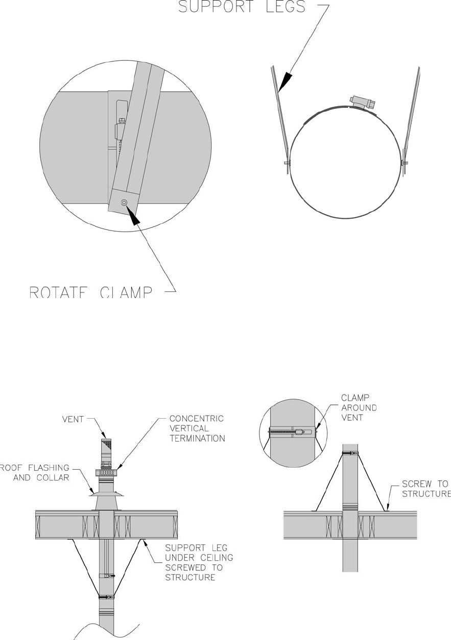
Support Clamp, (4_ _27SS): Support clamps are sold in pairs and can be clamped around the vent and suspended from a
rod or cable. They can be used singularly as a saddle clamp to rest the vent in and suspended from two (2) rods or cables.
Support Legs Rotated Horizontally: Support legs can be used on horizontal runs by rotating the clamp at the rivet
connection. The legs can be cut to shorter lengths if necessary.
Vertical Supports, (SC_ _VSL): Vertical support legs can be used above or below a structure for support. To install,
slide the support clamp over the end of the vent section, leaving the clamp loose. Position the support legs and install
two (2) screws through each leg into the structure. Tighten the clamp around vent pipe. The legs can be cut to shorter
lengths if necessary and can rotate around the support clamp at the rivet connection. By rotating the clamp to a horizontal
position the support legs can be used on horizontal runs.
35
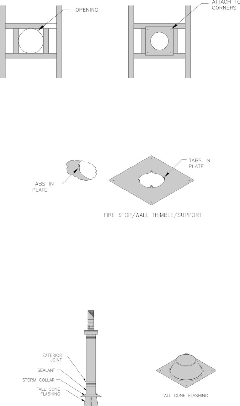
Fire Stop/Wall Thimble/Support, (SC_ _FS):
• The Saf-T Vent SC Fire Stop can be used as a fi restop, a wall thimble, or as a support plate.
• To use as a Wall Thimble prepare an opening according to the chart below. Remove any insulation from the opening,
using additional framing if necessary. Attach the plate over the center of the opening using appropriate fasteners.
• Install the vent section through the thimble plate and secure the section to the thimble by screwing the self-tapping
screws through the holes in the tabs on the plate and into the outer wall of the vent. Apply silicone sealant around the vent
section where it passes through the plate and around the plate where it is attached to the structure.
• To use as a Firestop before passing through ceilings or enclosed chases, prepare a round or square opening ¼” larger than
the outer jacket (5¼” for 3” vent or 7¼” for 4” vent). Remove any insulation from the opening. Secure the fi restop to
the structure at the four (4) corners. Install the vent section through the fi restop and secure to the thimble by screwing the
self-tapping screws through the holes in the tabs on plate and into outer wall of the vent. This method can also be used to
support the vent section either vertically or horizontally.
Tall Cone Flashing:
Directly On Roof or Curb:
Tall Cones are available for fl at (SC_ _TCF), 2/12 pitch (SC_ _TCFA), and 6/12 - 12/12 pitch roofs (SC_ _TCFB).
Prepare a square or round opening at least 1/4” larger than the outer jacket (5¼” for 3” vent or 7¼” for 4” vent). Remove
any insulation from the opening. Apply weather-stripping or outdoor caulk to the bottom of the cone plate and attach the
plate to the roof using common construction methods. Flash over the cone plate and seal the fastener heads using normal
roofi ng requirements. When the vent pipe is in place through the Tall Cone, attach a storm collar (sold separately) around
the pipe. Apply high temperature silicone sealant around the pipe where it passes through the top of the storm collar.
Continue to install vent sections as needed to meet the height requirements by code. Seal weather exposed joints of the
outer jacket with foil tape or an exterior grade silicone sealant.
36
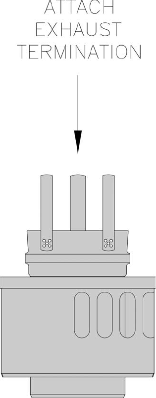
Vertical Terminations, (SC_ _VT): Install the vertical termination adapter into the last vent section and secure with the
three (3) self-tapping screws provided. If the exhaust termination needs to be extended, a section of EZ Seal vent can be
connected directly to the vertical termination adapter. Seal weather exposed joints of the outer jacket with foil tape or
an exterior grade silicone sealant. To allow for inspection of the system, do not seal the exhaust termination.
37
Vertical –
10. Installation of a vertical vent tee 8116304U is
required on all vertical vent applications. See
Figure 6. Attach vertical vent drain tee directly to
elbow or horizontal pipe from an elbow immediately
after vent connector.
11. Install fi re stops where vent passes through fl oors,
ceilings or framed walls. The fi re stop must close
the opening between the vent pipe and the structure.
Fire stop manufacturers are Air-Jet, American Metal
Products, Metal-Fab, and Simpson Dura-Vent.
12. Whenever possible install vent straight through roof.
Refer to Figure 13 if offset is necessary. Maintain
minimum clearance to combustible materials.
13. Install Vent Terminal.
a. Size roof opening to maintain minimum
clearance from combustible materials.
b. Use appropriately designed vent fl ashing
when passing through roofs. Follow fl ashing
manufacturers’ instructions for installation
procedures. Flashing manufacturers are Air-
Jet, American Metal Products, Metal Fab, and
Simpson Dura-Vent.
c. Extend vent pipe to maintain minimum vertical
and horizontal distance of twelve (12) inches
from roof surface. Allow additional vertical
distance for expected snow accumulation.
Provide brace as required. Refer to Figure 15.
d. Vertical venting requires fl ashing and a storm
collar to prevent moisture from entering the
structure.
e. Install storm collar on vent pipe immediately
above fl ashing. Apply Dow Corning Silastic 732
RTV Sealant between vent pipe and storm collar
to provide weathertight seal.
f. Attach vent terminal.
14. Install supplied air intake terminal onto collar of the
jacket enclosure. See Figure 16.
1. Do not exceed maximum vent length. Refer to
Table 4.
Horizontal –
2. Maintain minimum ¼ inch per foot slope in
horizontal runs.
3 Recommended horizontal installation consists of
vent being sloped down away from boiler. See
Figure 12.
4. Slope horizontal runs minimum ¼ inch per foot.
Slope towards vertical vent drain tee. Position weld
seams in vent pipes, in all horizontal runs, at the top
to avoid condensate from lying on the seams.
5. Use appropriately designed thimbles when passing
through combustible walls (thimble use optional
for noncombustible walls). Insert thimble through
wall from outside. Secure outside fl ange to wall
with nails or screws, and seal with sealant material.
Install inside fl ange to inside wall, secure with nails
or screws, and seal with sealant material.
6. For noncombustible wall application when thimble
is not used, size opening such that female (bell) end
with locking band attached cannot pass through.
7. Join vent terminal to vent pipe. Locate vent
terminal between seventeen (17) inches and twenty-
nine (29) inches from wall when joined to inside
vent piping. See Figure 14.
8. Insert vent pipe through thimble/opening from
outside and join to vent system. Apply sealant
between vent pipe and opening/thimble to provide
weathertight seal.
9. Join vent terminal to 45° elbow included in kit. Join
45° elbow/terminal assembly to vent pipe. Refer
to Section C for proper procedures for joining vent
pipe and fi ttings. See Figure 3 .
H. Indoor Air Installation – See Figures 12, 13, 14, 15 and 16.
38
Figure 12: Recommended Separate Horizontal - Vent Installation
39
Figure 13: Alternate Separate Horizontal - Vent Installation
40
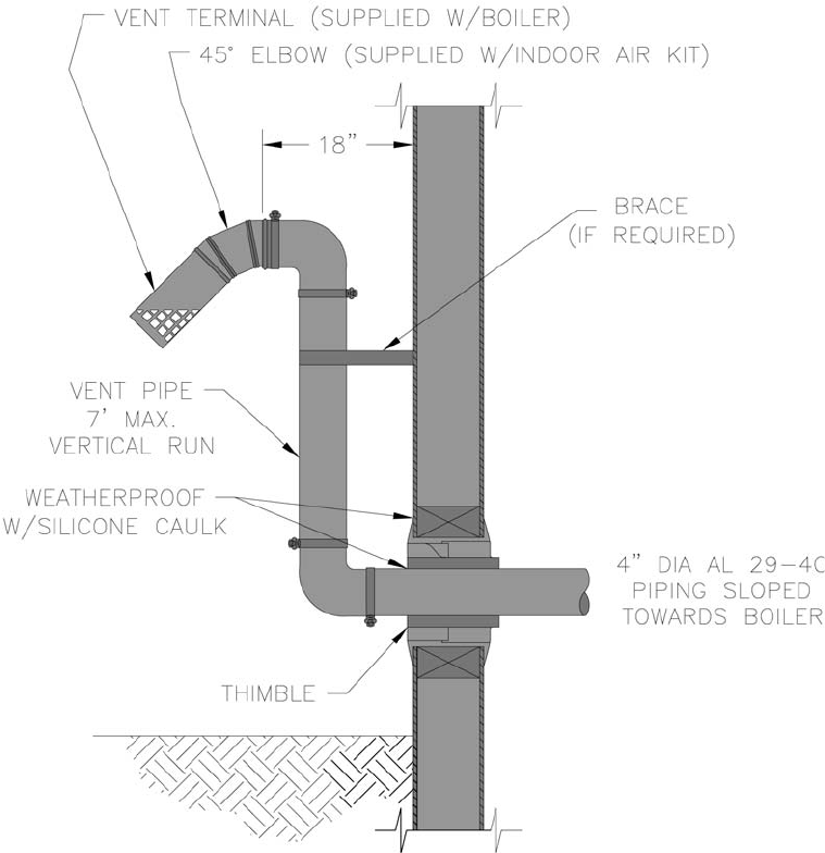
Figure 15: Indoor Air - Horizontal / Vertical Vent Terminal Installation
Extend Vent/Air Intake Piping to maintain minimum vertical (“X”) and minimum horizontal (“Y”) distance of twelve
(12) inches from roof surface. Allow additional vertical (“X”) distance for expected snow accumulation.
Figure 14: Optional Indoor Air - 3” or 4” Vent Terminal Installation
Figure 16: Indoor Air - Air Intake Terminal Installation
41
1. Do not exceed maximum vent/air intake lengths.
Refer to Table 4.
2. This installation will allow a maximum of fi ve (5)
feet vertical exterior run of the vent/air intake piping
to be installed on separate horizontal venting and
indoor air horizontal venting.
ECITON
tnelaviuqenidedulcniebotnurroiretxE
.shtgnelekatniria/tnev
3. Install vent piping.
a. Install vent piping for desired venting system.
Refer to specifi c section for details for vent pipe
installation.
b. After penetrating wall/thimble, install an
AL 29-4C® 90° elbow so that elbow leg is in the
up direction.
c. Install maximum of fi ve (5) feet of AL 29-4C®
vent pipe. Refer to Sections C through E for
proper procedures for joining vent pipe and
fi ttings.
I. Optional Exterior Separate Horizontal Vent/Air Intake Terminal Mounting – See Figures 17, 18, 19, 20, 21 and 22.
d. At top of vent pipe length install an AL 29-4C®
90° elbow so that elbow leg is opposite the
building’s exterior surface.
e. If installation requires indoor air, install
AL 29-4C® 45° elbow (provided in indoor air kit)
to upper AL 29-4C® 90° elbow so that leg of 45°
is in down direction (see Figure 21 or 22). If not
using indoor air, proceed to Step f.
f. Install horizontal vent terminal (provided with
boiler).
g. Brace piping if required.
4. Air Intake Piping (not required for indoor air).
a. Install air intake piping for desired venting
system. Refer to specifi c section for details for
air intake installation.
b. After penetrating wall, install a corrosion
resistant 90o elbow so that elbow leg is in the up
direction.
c. Install maximum of fi ve (5) feet of corrosion
resistant air intake pipe.
d. At top of air intake pipe install air intake
terminal (provided with boiler).
e. Brace piping if required.
Figure17: Optional Separate Horizontal Air 3” or 4” Intake Terminal Installation
42
Figure 18: Optional Separate Horizontal Air 5” Intake Terminal Installation
Figure 19: Optional Separate Horizontal 3” Vent Terminal Installation
43
Figure 20: Optional Separate Horizontal 4” Vent Terminal Installation
Figure 21: Optional Separate Horizontal 3” Vent Terminal Installation (Indoor Air)
44
Figure 22: Optional Separate Horizontal 4” Vent Terminal Installation (Indoor Air)
45
A. Design and install boiler and system piping to
prevent oxygen contamination of boiler water and
frequent water additions.
1. There are many possible causes of oxygen
contamination such as:
a. Addition of excessive make-up water as a result
of system leaks.
b. Absorption through open tanks and fi ttings.
c. Oxygen permeable materials in the distribution
system.
2. In order to insure long product life, oxygen sources
must be eliminated. This can be accomplished by
taking the following measures:
a. Repairing system leaks to eliminate the need for
addition of make-up water.
b. Eliminating open tanks from the system.
c. Eliminating and/or repairing fi ttings which allow
oxygen absorption.
d. Use of non-permeable materials in the
distribution system.
e. Isolating the boiler from the system water by
installing a heat exchanger.
f. Use properly designed and operating air
elimination devices in water piping.
B. Low Water Cut Off (LWCO) on Hot Water Boilers
(Optional)
GNINRAW
otseriwyrotcaftucotTPMETTATONOD
ffOtuCretaWwoLtekramretfanallatsni
snoitcennocesuylnO.)OCWL(
tuCretaWwoLrofdeifitnediyllacificeps
.ffO
ffOtuCretaWwoLehtwollof,sesacllanI
.snoitcurtsnis'rerutcafunam)OCWL(
When
A low water cutoff is required to protect a hot water
boiler when any connected heat distributor (radiation)
is installed below the top of the hot water boiler (i.e.
baseboard on the same fl oor level as the boiler). In
IV. Water Piping and Trim
addition, some jurisdictions require the use of a LWCO
with a hot water boiler.
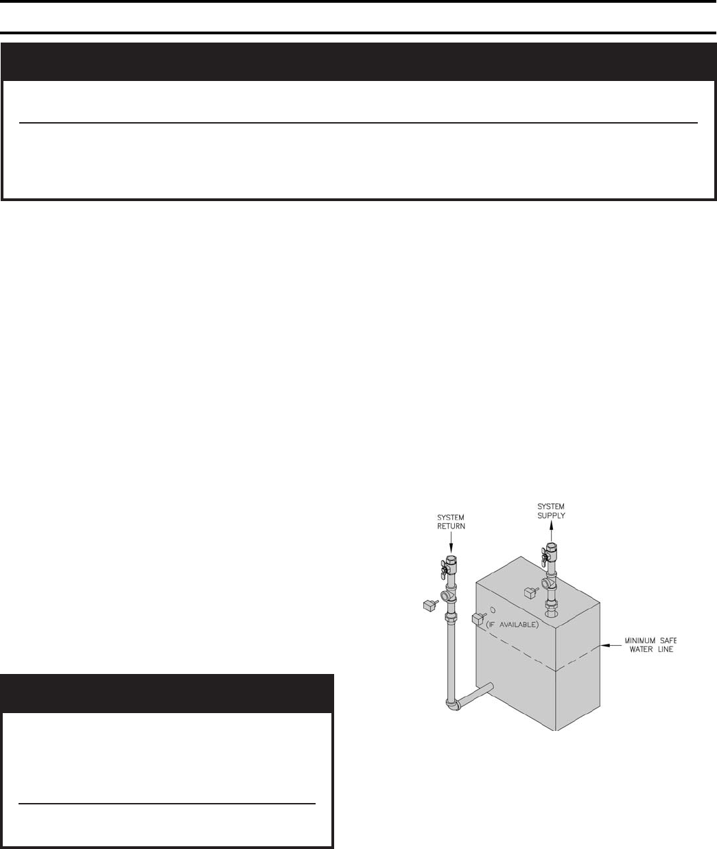
Where
The universal location for a LWCO on both gas and oil
hot water boilers is above the boiler, in either the supply
or return piping. The minimum safe water level of a
water boiler is at the uppermost top of the boiler; that is,
it must be full of water to operate safely.
What Kind
The SCG boiler is designed to accept the wiring of the
Safgard Model 1100-H4 (P/N 45-1104) LWCO. This is
a probe type LWCO. The factory wiring is designed to
allow simple “Plug-in” installation of the wiring.
How to Pipe
A “tee” is commonly used to connect the probe LWCO
to the supply or return piping, as shown below.
GNINRAW
roreliobotegamaddnanoitareporeporpminitluseryamreliobepipylreporpoteruliaF
.erutcurts
reliobleetsdnanorifonoisorrocesuaclliwretawreliobfonoitanimatnocnegyxO
revoctonseodytnarraWdradnatSs'mahnruB.eruliafreliobotdaelnacdna,stnenopmoc
desuacpu-dliub)emil(elacsroretawreliobfonoitanimatnocnegyxoybdesuacsmelborp
.retawfonoitiddatneuqerfyb
LWCO Location
Select the appropriate size tee using the LWCO
manufacturer’s instructions. Often, the branch
connection must have a minimum diameter to prevent
bridging between the probe and the tee. Also, the run
of the tee must have a minimum diameter to prevent
the end of the probe from touching or being located too
close to the inside wall of the run of the tee.
Ideally, manual shutoff valves should be located
above the LWCO and the boiler to allow for servicing.
This will allow probe removal for inspection without
46
draining the heating system. Many probe LWCO
manufacturers recommend an annual inspection of the
probe.
How to Wire
Ensure power is turned off to boiler.
Locate the LWCO jumper wire in the factory wiring
harness. Remove the jumper wire and install
the LWCO wiring from LWCO Model 1100-H4
(P/N 45-1100) into the plug of the SCG factory wiring.
How to Test
Shut off fuel supply. Lower water level until water
level is BELOW the LWCO. Generate a boiler demand
by turning up thermostat. Boiler should not attempt to
operate. Increase the water level by fi lling the system.
The boiler should attempt to operate once the water
level is above the LWCO.
ECITON
ehtniOCWLehtfonoitacolehterusnE
ehtfonoitcennocrofwollalliwgnipip
gniriwyrotcafehtotssenrahgniriwOCWL
.G
CSehtfo
C. Connect system supply and return piping to boiler.
See Figures 25 and 26. Maintain minimum ½ inch
clearance from hot water piping to combustible
materials.
ECITON
metsysehtgnizissdnemmocermahnruB
ot)MPG(wolftneiciffusylppusotrotalucric
ehtnilaitnereffiderutarepmetF°
02awolla
eht,rotalucricmetsysehtgnizisnehW.metsys
dnadraobesab,srotaidarllafoporderusserp
ebtsumgnipipgn
itcennoclladnagnibuttnaidar
.deredisnoc
D. Install circulator with fl anges, gaskets and bolts
provided. Circulator harness allows circulator to be
mounted on supply or return. Connect harness to
circulator and secure any excess conduit.
E. Install supply manifold, pressure/temperature gauge
and pressure relief valve.
See Figure 24. Pressure Relief Valve must be installed
with spindle in vertical position. Installation of the
relief valve must comply with the ASME Boiler and
Pressure Vessel Code, Section IV.
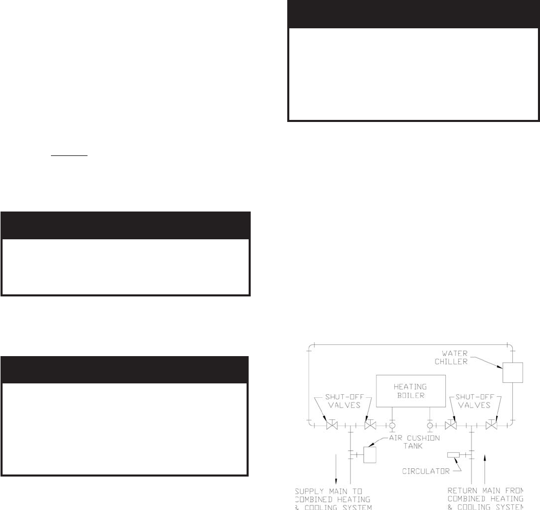
Figure 23: Recommended Piping for Combination
Heating & Cooling (Refrigeration) System
GNINRAW
tsumgnipipegrahcsidevlavfeilererusserP
erevesfolaitnetopehttahthcusdepipeb
ynaniepipTONOD.detanimilesisnrub
TONOD.ruccodluocgnizeerferehwaera
.spacrosgulp,sevlavffo-tuhsynallatsni
egrahcsidreporprofsedoClacoLtlusnoC
.tnemegnarragnipip
F. Space heating and domestic water heating with
Alliance™ water heater. Install Alliance water heater as
a separate heating zone. Refer to Alliance Installation,
Operating and Service Instructions for additional
information.
G. If boiler is used in connection with refrigeration
systems, boiler must be installed with chilled medium
piped in parallel with the heating boiler using
appropriate valves to prevent chilled medium from
entering boiler, see Figure 23.
H. If boiler is connected to heating coils located in
air handling units where they may be exposed to
refrigerated air, boiler piping must be equipped with
fl ow control valves to prevent gravity circulation of
boiler water during operation of cooling system.
I. Use a boiler bypass if the boiler is to be operated
in a system which has a large volume or excessive
radiation where low boiler water temperatures may be
encountered (i.e. converted gravity circulation system,
etc.).
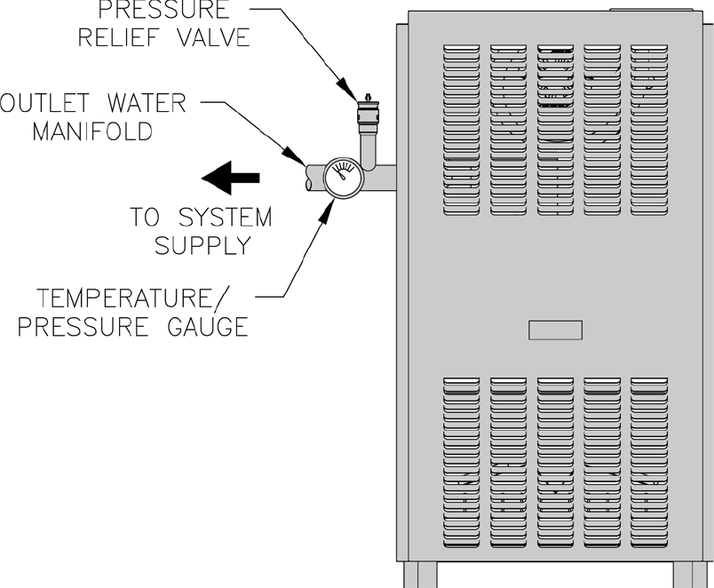
47
Figure 24: Supply Water Manifold Piping
Install pipe tee between circulator and boiler return
along with second tee in supply piping as shown in
Figure 25 or 26. Bypass should be same size as the
supply and return lines with valves located in bypass
and supply outlet as illustrated in Figure 25 or 26 in
order to regulate water fl ow to maintain higher boiler
water temperatures.
After the boiler is operational (reference Section VIII.
System Start-Up) set by-pass and boiler supply valves
to half throttle position to start. Operate boiler until
system water temperature reaches normal operating
range.
Adjust valves to provide 180° to 200°F supply water
temperature. Opening the boiler supply valve will raise
system temperature, while opening the by-pass valve
will lower system supply temperature.
J. A hot water boiler installed above radiation level
must be provided with a low water cutoff device as part
of installation.
K. If a low water cutoff is required, it must be mounted
in the system piping above the boiler. The minimum
safe water level of a hot water boiler is just above the
highest water containing cavity of the boiler; that is, a
hot water boiler must be full of water to operate safely.
L. Oil, grease, and other foreign materials which
accumulate in new hot water boilers and a new
or reworked system should be boiled out, and
then thoroughly fl ushed. A local qualifi ed water
treatment chemical specialist is a suggested source
for recommendations regarding appropriate chemical
compounds and concentrations which are compatible
with local environmental regulations.
M. After the boiler and system have been cleaned and
fl ushed, and before refi lling the entire system add
appropriate water treatment chemicals, if necessary, to
bring the pH between 7 and 11.
N. If it is required to perform a long term pressure
test of the hydronic system, the boiler should fi rst be
isolated to avoid a pressure loss due to the escape of air
trapped in the boiler.
To perform a long term pressure test including the
boiler, ALL trapped air must fi rst be removed from the
boiler.
A loss of pressure during such a test, with no visible
water leakage, is an indication that the boiler contained
trapped air.
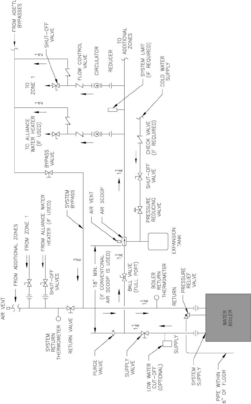
48
Figure 25: Recommended Water Piping for Circulator Zoned Heating Systems
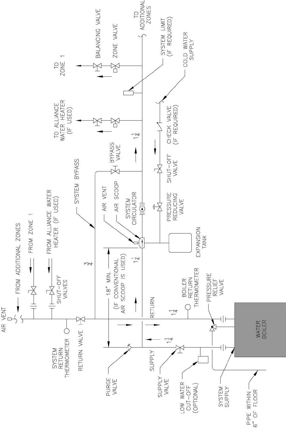
49
Figure 26: Recommended Water Piping for Zone Valve Zoned Heating Systems
50
V. Gas Piping
Table 5: Gas Ratings
For materials or conditions other than those listed
above, refer to National Fuel Gas Code, NFPA54/ANSI
Z223.1, or size system using standard engineering
methods acceptable to authority having jurisdiction.
Table 6: Specifi c Gravity Correction Factors
GNINRAW
otylppussagepipylreporpoteruliaF
dnanoitareporeporpminitluseryamreliob
syawlA.erutcurtsroreliobehtotegamad
eerfkaelyletulosbasignipipsagerussa
ehtrofepytdnaezisreporpehtfodna
.daoldetcennoc
yamrotalugererusse
rpsaglanoitiddanA
.reilppussagtlusnoC.dedeeneb
A. Size gas piping. Design system to provide adequate gas
supply to boiler. Consider these factors:
1. Allowable pressure drop from point of delivery to
boiler. Maximum allowable system pressure is ½
psig. Actual point of delivery pressure may be less;
contact gas supplier for additional information.
Minimum gas valve inlet pressure is stamped on
the rating label located in the boiler’s vestibule
compartment.
2. Maximum gas demand. Refer to the boiler’s input
as printed on it’s rating label. Also consider existing
and expected future gas utilization equipment (i.e.
water heater, cooking equipment).
3. Length of piping and number of fi ttings. Refer to
Table 7 for maximum capacity of Schedule 40 pipe.
Table 8 lists equivalent pipe length for standard
fi ttings.
4. Specifi c gravity of gas. Gas piping systems for
gas with a specifi c gravity of 0.70 or less can be
sized directly from Table 7, unless authority having
jurisdiction specifi es a gravity factor be applied.
For specifi c gravity greater than 0.70, apply gravity
factor from Table 6. If exact specifi c gravity is not
shown choose next higher value.
ECITON
yllaicepsebotdeenlevelaesevobateef999,4nahtretaergsedutitlaroftliubsreliobGCS
neebsahledoM"H"reliobGCSehT.snoiitidnoccirehpsomtanisegnahcroftsujdaotdecifiro
situpnI.levelaesevobateef000,01ot000,5morfsnoitidnoccirehpsomtanietarepootdeifitrec
000,01tasnoitacilpparof%02dna,levelaesevobateef000,5tasnoitacilpparof%01ybdetared
.teef0001repnoitcuder%2nodesabsietareD.slevelaesevobateef
aesevobateef999,4-0ledoM"S"ehT:sledoMedutitla)2(owtnielbaliavasireliobGCSehT
.levelaesevobateef000,01-000,5ledoM"H"ehtdna,level
.re
rutcafunamehttlusnoc,teef000,01evobasnoitacilpparoF
cificepS
ytivarG
noitcerroC
rotcaF
cificepS
ytivarG
noitcerroC
rotcaF
--------58.018.0
--------09.028.0
06.000.100.187.0
56.069.001.147.0
07.039.002.117.0
57.009.003.186.0
08.078.004.166.0
relioB
ledoM
rebmuN
PL/larutaN
mumixaM
erusserPsaG
).c.w.ni(
larutaNmuminiM
erusserPsaG
).c.w.ni(
evlaVsaGottel
nI
PLmuminiM
erusserPsaG
).c.w.ni(
evlaVsaGottelnI
larutaN
dlofinaM
erusserP
).c.w.ni(
PL
dlofinaM
erusserP
).c.w.ni(
3-GCS
415.45.115.35.01
4-GCS
5-GCS
6-GCS
7-GCS
8-GCS
9-GCS
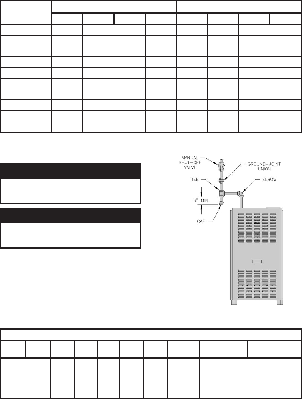
51
Table 7: Maximum Capacity of Schedule 40 Pipe in CFH* For Gas Pressures of 0.5 psig or Less
Figure 27: Recommended Gas Piping
Table 8: Equivalent Lengths of Standard Pipe Fittings & Valves
B. Connect boiler gas valve to gas supply system.
GNINRAW
nosdnuopmocdaerhtreporpesuoteruliaF
foskaelnitluseryamsrotcennocsaglla
.sagelbammalf
GNINRAW
ebtsummetsysdnareliobotylppussaG
rognillatsniotroirpffotuhsyletulosba
.gnipipsagreliobgnicivres
1. Use methods and materials in accordance with local
plumbing codes and requirements of gas supplier. In
absence of such requirements, follow National Fuel
Gas Code, NFPA 54/ANSI Z223.1.
2. Use thread (joint) compounds (pipe dope) resistant
to action of liquefi ed petroleum gas.
3. Install sediment trap, ground-joint union and manual
shut-off valve upstream of boiler gas control valve
and outside jacket. See Figure 27.
* 1 CFH of Natural Gas is approximately equal to 1 MBH; 1 CFH of LP is approximately equal to 2.5 MBH; con-
tact your gas supplier for the actual heating value of your gas.
htgneL
]teeF[
porDerusserP.c.whcni3.0 porDerusserP.c.whcni5.0
½¾ 1 ¼1½¾1¼1
01231872025050,1571063086004,1
0229091053037021052564059
033725158209579002573077
043603154200528071023066
056551151204437151582085
0605501591004668310620
35
07646908107316521042094
08340907105375811022064
09044806102335011502034
001839705150305301591004
NEPOYLLUFSEVLAV
epiP
eziS
.D.I
sehcnIetaGebolGelgnA
gniwS
kcehC
°09
woblE
°54
woblE
wolF,eeT°09
nuRhguorhT
wolF,eeT°09
hcnarBhguorhT
"½226.053.06.813.93.46.187.00.11.3
"¾428.044.01.325.113.51.279.04.11.4
"1940.165.04.927.418.66.232.18.13.5
"¼1083.147.06.833.919.85.306.13.29.6

52
4. All above ground gas piping upstream from manual
shut-off valve must be electrically continuous and
bonded to a grounding electrode. Do not use gas
piping as grounding electrode. Refer to National
Electrical Code, NFPA 70.
C. Pressure test. The boiler and its gas connection must
be leak tested before placing boiler in operation.
1. Protect boiler gas control valve. For all testing over
½ psig, boiler and its individual shutoff valve must
be disconnected from gas supply piping. For testing
at ½ psig or less, isolate boiler from gas supply
piping by closing boiler’s individual manual shutoff
valve.
2. Locate leaks using approved combustible gas
detector, soap and water, or similar nonfl ammable
solution.
REGNAD
semalfnepo,seldnac,sehctamesutonoD
.skaelrofkcehcotecruosnoitingirehtoro
53
VI. Electrical
GNINRAW
lacisyhpsuoiresnitluseryamreliobehtotsnoitcennoclacirtceleeriwylreporpoteruliaF
.mrah
erofebffosirewopl
laerusekaM.ecruosenonahterommorfebyamrewoplacirtcelE
.krowlacirtceleynagnitpmetta
.ecivedtnerruc-revodezisylreporpahtiwdetcetorpebtsumreliobhcaE
.slortnocgnitareporoytefasynaevitareponiekamrotuopmujreveN
reliobhcaE.ylnosesoprupecnereferroferalaunamsihtnideniatnocsmargaidgniriwehT
ehtdnamargaidsihtotrefeR.roodtnorfehtotdehcattamargaidgniriwahtiwdeppihssi
gniriwllawollofdnadnatsrednu,daeR.reliobehthtiwdesuslortnocynafomargaidgniriw
.slortnocehthtiwdeilppussnoitcurtsni
A. General. Install wiring and electrically ground boiler
in accordance with authority having jurisdiction or, in
the absence of such requirements, follow the National
Electrical Code, NFPA 70, and/or CSA C22.1 Electrical
Code.
B. A separate electrical circuit must be run from
the main electrical service with an over-current
device/disconnect in the circuit. A service switch is
recommended and may be required by some local
jurisdictions. Install the service switch in the line
voltage “Hot” leg of the power supply. Locate the
service switch such that the boiler can be shut-off
without exposing personnel to danger in the event of
an emergency. Connect the main power supply and
ground to the three (3) boiler wires (black, white and
green) located in the junction box at the inside top of
the boiler jacket. If a low water cutoff is to be used,
connect the low water cutoff so that all 120V power
to boiler is interrupted if the low water cutoff’s switch
opens.
C. Refer to Figures 28 and 29 for details on the internal
boiler wiring.
ECITON
fogniriwlanretniehtedisnidetacoltimilerutarepmetretawhgihahtiwdeppiuqesireliobsihT
sdeecxeerutarepmetretawreliobehttneveehtninwodtuhsreliobsedivorptimilsihT.reliobeht
erutarepmetretawlanoitiddanaeriuqersedoClacoLniatreC.lortnoctimilehtfotniopteseht
tesmuminimehtwolebserutarepmettaetarepoyamsmetsysfosepytniatrec,noitiddanI.timil
.reliobehtnideniatnoctimilehtfotniop
nidetacol)tatsauqA6004LllewyenoH(timilerutarepmetretawlanoitiddanallatsni,sruccosihtfI
saeriW.launamsihtfonoitceSmirTdnagnipiPretaWehtninwohssag
nipipmetsyseht
.launamsihtfonoitceSlacirtcelEehtnidetacidni
ECITON
.detonesiwrehtosselnudeilppusrellatsniera.cteslortnoc,stuneriw,eriwllA
REGNAD
ecivresronoitallatsnignitpmettaerofebderewopnuerasnoitcennoclacirtcelellaerussaylevitisoP
htiwsexoblacirtcelellatuokcoL.gnidliubroreliobehtfosnoitcennocrostnenopmoclacirtcelefo
.ffodenrutsirewopecnokcoldap
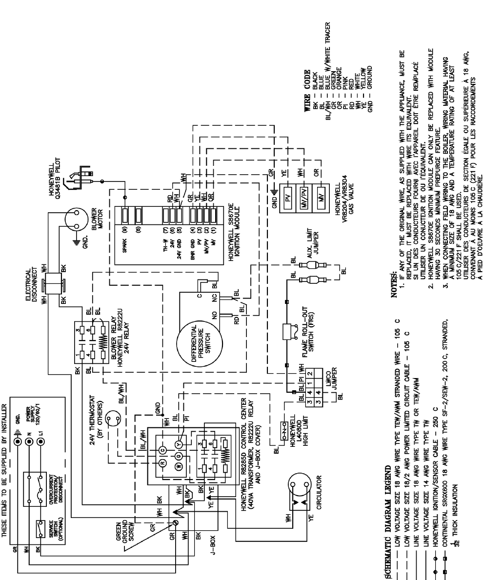
54
Figure 28: Internal Boiler Wiring Schematic Diagram
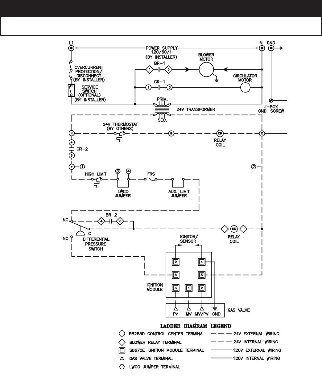
55
Figure 29: Internal Boiler Wiring Ladder Diagram
ECITON
ehtninwohsrepmujtimilyrailixuaehthtiwseiresnillatsni,desusitimilmetsyslanoitiddanafI
.wolebgniward

56
D. System Controls and Wiring
1. Refer to National Electric Code or Local Electric Codes for proper size and type of wire required. Follow Code.
2. Use anti-short bushings on all wiring passing through boiler jacket, junction boxes and/or control boxes.
3. Use armored cable (BX) over all exposed line voltage wiring.
4. If an Alliance™ indirect water heater is used, use priority zoning except for Hydro-Air Systems.
5. Single Zone Heating System – Refer to Figure 30 of this manual for the electrical diagram for this type of system.
Set the thermostat heat anticipator to 0.60 amps.
6. Single Zone Heating System with Alliance™ Water Heater - Refer to Figure 31 of this manual for the electrical diagram
for this type of system.
Set the thermostat heat anticipator to 0.60 amps.
7. Conventional Circulator Zoned System – Refer to Figure 32 of this manual for the electrical diagram for this type of
system.
Read, understand and follow all of the instructions provided with the Honeywell R8888 control.
Connect the thermostat of each zone and the circulator for that zone to R8888 panel. If an Alliance™ indirect water
heater is used, connect the Alliance™ thermostat and circulator to the Zone 1 terminals of the R8888.
Set the thermostat heat anticipator to 0.12 amps.
ECITON
enoz)4(ruofadna)A8888R(ledoMenoz)3(eerhtanielbaliavasilortnoC8888RllewyenoHehT
evlewtotpuroflortnocedivorpotrehtegotdesuebyams'8888R)4(ruofotpU.)B8888R(ledoM
ytiroirpedivorplliw,lortnocniamehtfoenoztsrifeht,enoz)1(enoylnO.senozlaudividni)21(
,Aehtgniriwybs'8888Rlanoitiddatcennoc,deriuqererasenoz)4(ruofnahteromfI.noitalucric
fI.ylppusrewoptlov021aseriuqer8888RhcaE.rehtegotlortnochcaefoslanimretCdna,B
tesdna8888Rtsrifehtno"niam"othctiwsepytlenapehttes,desusi8888R)1(enonahterom
.8888Rhtruofrodriht,dnocesehtno
"noisnapxe"othctiwsepytlenapeht
8. Conventional Zone Valve Zoned System – Refer to Figure 33. Wiring to the most popular models of zone valves is given
in Figure 34.
Connect the thermostat of each zone and the zone valve for that zone to the R8889 control. If an Alliance™ indirect water
heater is used, connect the Alliance™ thermostat and zone valve to the “zone 1” terminals of the R8889.
Set the thermostat heat anticipator to 0.12 amps.
ECITON
enoz)4(ruofowtdnasledomenoz)3(eerhtowtnielbaliavasilortnoC9888RllewyenoHehT
ledoMdnasmetsysenoz)3(eerh
trofA9888RledoMgnisusdnemmocermahnruB.sledom
yamdnayticapacdaolsselevahD9888RdnaC9888RsledoM.smetsysenoz)4(ruofrofB9888R
otrehtegotdesuebyams'9888R)4(ruofotpU.sevlavenozfosepytniatrechtiwetarepoton
lortnocniamehtfoenoztsrifeht,enoz)1(enoylnO.senozlaudividni)61(neetxisotpuedivorp
erasenoz)4(ruofnahteromfI.retaehretawtceridniecnaillAehtrofgninozytiroirpedivorplliw
.rehtegotlortnochcaefoslanimretCdnaB,Aehtgniriwybs'9888Rlanoitiddatcennoc,deriuqer
lenapehttes,desusi9888R)1(enonahteromfI.ylppusrewoptlov021aseriuqer9888RhcaE
ehtno"noisnapxe"othctiwsepytlenapehttesdna9888Rtsrifehtno"niam"othctiwsepyt
.9888Rhtruofrodriht,dnoces
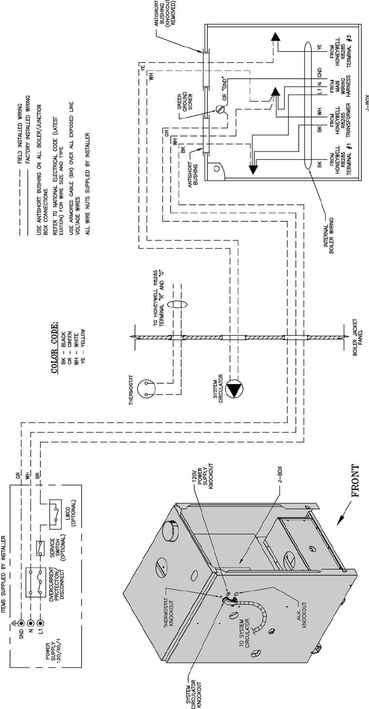
57
Figure 30: System Wiring Schematic for Single Zone Space Heating Only
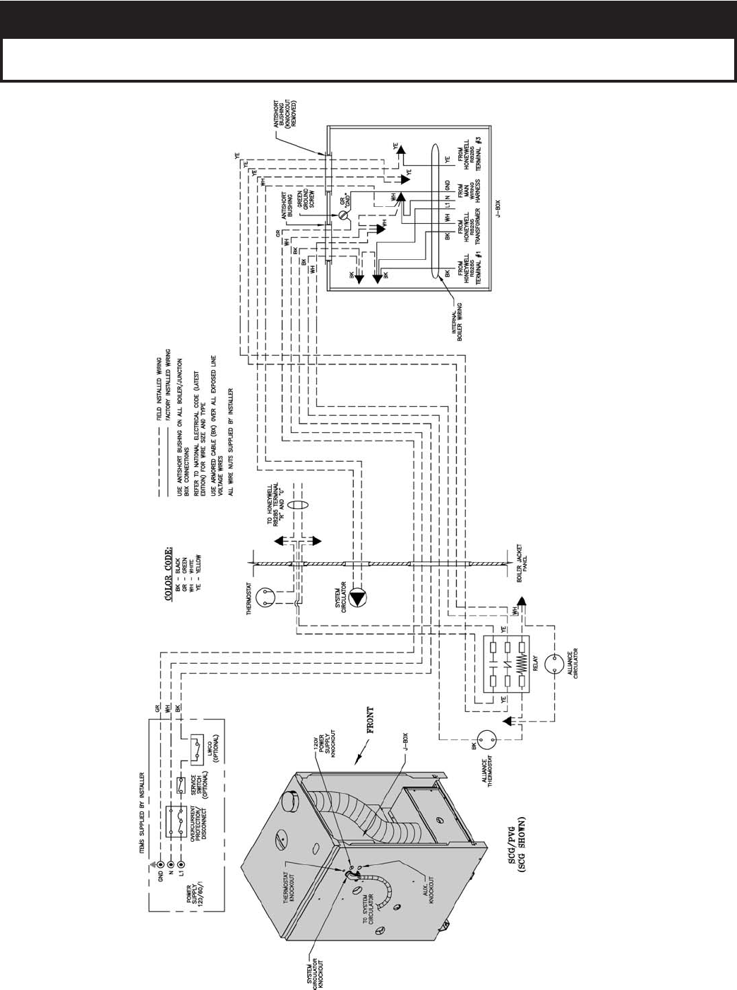
58
Figure 31: Single Zone System with Packaged Alliance™ Water Heater Wiring Schematic
ECITON
ehtninwohsrepmujtimilyrailixuaehthtiwseiresnillatsni,desusitimilmetsyslanoitiddanafI
.wolebgniward
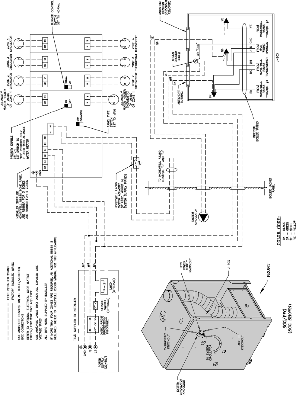
59
Figure 32: Circulator Zoned System Wiring Schematic
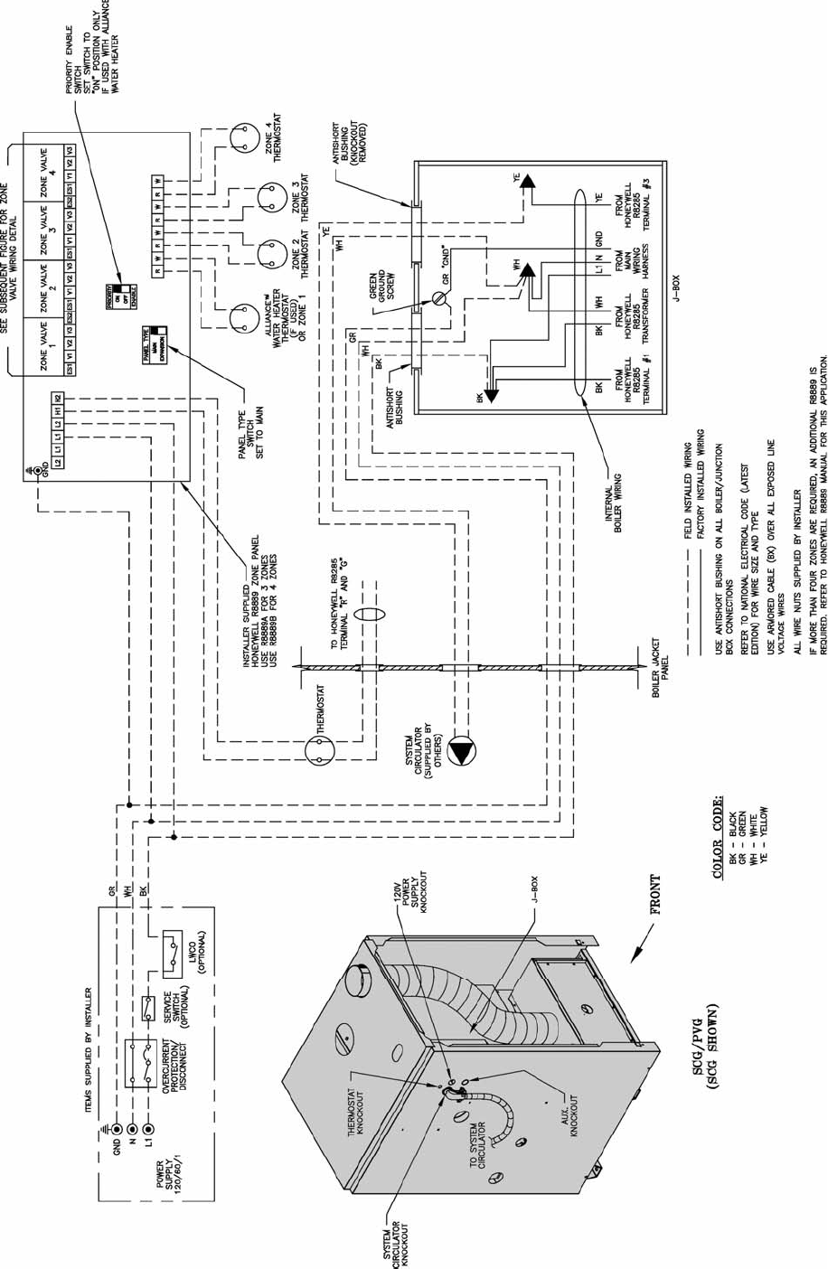
60
Figure 33: Zone Valve Zoned System Wiring Schematic
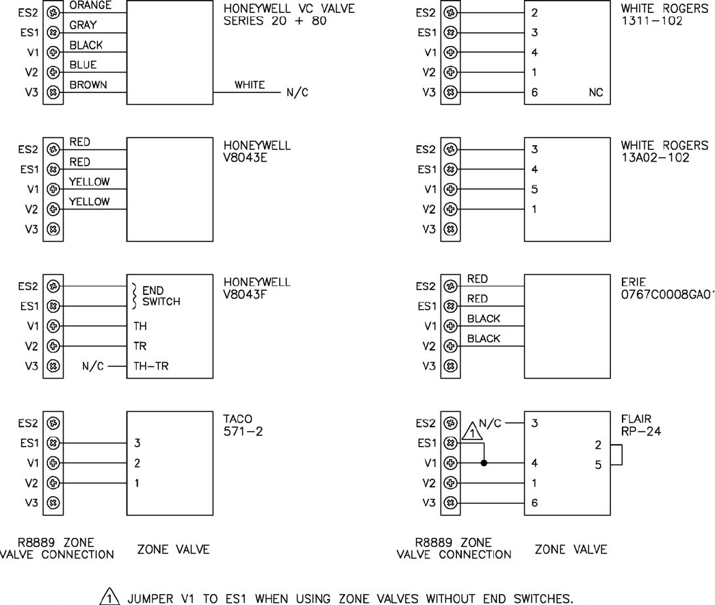
61
Figure 34: Different Manufacturer’s Zone Valve Connections to Honeywell R8889
62
A. General Guidelines
1. Read and follow all venting, combustion air,
water piping, gas piping and electrical instructions
contained in this manual unless otherwise instructed
in this section.
2. Consult Local Building Codes or National Fuel Gas
Code, NFPA 54/ANSI Z222.3 for restrictions and
instructions on modular boiler installations.
B. Module Sizing
Burnham recommends sizing each boiler in a modular
system to provide 20 % of the combined heating load
where ever possible.
C. Venting
1. Each boiler must have an individual vent pipe.
Refer to Venting Section of this manual for venting
guidelines and options.
GNINRAW
.rehtegotsepiptnevdlofinamtonoD
2. The maximum vent length for each boiler is fi fty
(50) equivalent feet.
3. The minimum horizontal distance between vent
terminations is one (1) foot. Additional horizontal
distance is desirable to avoid frost damage to the
building. Vent terminations must be at least twelve
(12) inches above the ground plus the expected
snow accumulation.
NOITUAC
esolcsnoitanimrettnevelpitlumgnillatsnI
nopudliubtsorfsetomorprehtegot
,ytilibissopsihteziminimoT.sgnid
liub
ehtotgnidliubehtmorfecnatsidehtdnetxe
ehtesaercnidnanoitanimrettnevehtfodne
.snoitanimretneewtebecnatsidlatnoziroh
4. Multiple vertical vent pipes may be piped through
a common conduit or chase so that one roof
penetration may be made. Each vent termination
must be one (1) foot from other terminations.
D. Air Intake Piping
1. Each boiler must have an individual air intake pipe,
refer to Venting Section of this manual for Air Intake
Guidelines and Options.
2. The maximum air intake length for each boiler is
fi fty (50) equivalent feet.
3. Locate air intake termination on the same wall as
the vent termination if possible, to prevent nuisance
boiler shutdowns. However, boiler may be installed
with vertical venting and sidewall combustion air
inlet (or visa versa) if installation conditions do not
allow alternate arrangement.
VII. Modular Installation
Table 9: Modular Boiler Water Manifold Sizing
E. Water Piping (See Table 9)
Installing a low water cutoff in the system piping of
modular systems is strongly recommended and may be
required by Local Codes.
F. Gas Piping
1. Refer to National Fuel Gas Code, Local Codes and
Tables 7 and 8 for gas pipe sizing.
2. Each boiler must be piped as shown in Figure 27.
GNINRAW
evobasignidliubehtnierusserpsagfI
rotalugererusserpsaglanoitiddana,gisp½
rotalugerlanoitiddaenognisU.deriuqersi
efasnunitluseryamsreliobelpitlumrof
rotalugerlanoitiddaehT.noitareporeliob
sagetalugerylreporpo
telbaebtsum
.reliobtsellamsehtfotupniehttaerusserp
eromroowt,sihtodtonnacrotalugerehtfI
tlusnoC.deriuqererasrotalugerlanoitidda
saglacolro/dnarerutcafunamrotaluger
tnempiuqednasnoitcurtsnirofreilppus
.sgnitar
G. Electrical
1. Each boiler must be provided with a fused
disconnect and service switch.
2. Install wiring in accordance with requirements of
authority having jurisdiction. In the absence of such
requirements, follow the National Electric Code,
NFPA 70 and/or CSA C22.1 Electric Code.
H. Modular Boiler Control Systems
Contact a controls manufacturer such as Honeywell or
Tekmar to properly apply a modular control system.
Common systems may use outdoor temperature, return
water temperature or both to stage the boilers.
tuptuOdenibmoC
)HBM(
muminiMdednemmoceR
dlofinaMretaWnommoC
)TPN(eziS
< 661"¼1
< 062"½1
< 055"2
< 009"½2
< 0002"3
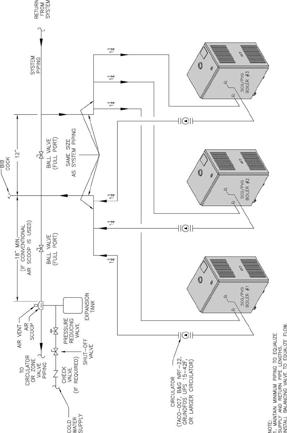
63
Figure 35: Modular Boiler Gas Piping
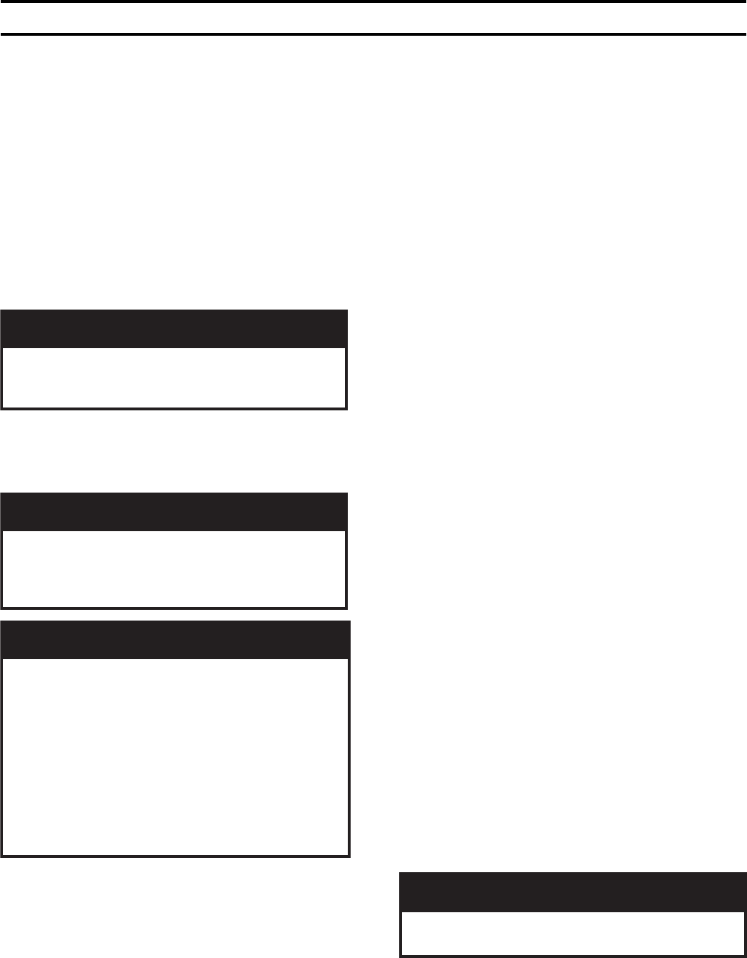
64
A. Safe operation and other performance criteria were
met with gas manifold and control assembly provided
on boiler when boiler underwent tests specifi ed in
American National Standard for Gas-Fired Low-
Pressure Steam and Hot Water Boilers, ANSI Z21.13.
B. Verify that the venting, water piping, gas piping and
electrical system are installed properly. Refer to
installation instructions contained in this manual.
C. Confi rm all electrical, water and gas supplies are
turned off at the source and that vent is clear of
obstructions.
D. Confi rm that all manual shut-off gas valves between
the boiler and gas source are closed.
GNINRAW
llawollofdnadnatsrednu,daeryletelpmoC
erofeblaunamsihtnisnoitcurtsni
.putratsgnitpmetta
E. Fill entire heating system with water and vent air
from system. Use the following procedure on a Series
Loop or multi-zoned system installed as per Figure 25
or 26 to remove air from system when fi lling.
GNINRAW
sihtfoerusserpgnitarepomumixamehT
sihtdeecxereveN.gisp03sireliob
erusserpegnahcrogulptonoD.erusserp
.evl
avfeiler
ECITON
mretgnolamrofrepotderiuqersitifI
eht,metsyscinordyhehtfotseterusserp
adiovaotdetalosiebtsrifdluohsreliob
riafoepacseehtoteudssolerusserp
.reliobehtnideppart
tseterusserpmretgnolamrofrepoT
tsumriadeppartLLA,re
liobehtgnidulcni
.reliobehtmorfdevomerebtsrif
htiw,tsetahcusgniruderusserpfossolA
noitacidninasi,egakaelretawelbisivon
.riadeppartdeniatnocreliobehttaht
1. Close full port ball valve in boiler supply piping.
2. Isolate all zones by closing zone valves or shut-off
valves in supply and return of each zone(s).
3. Attach a hose to the vertical hose bib located prior to
the full port ball valve in the system supply piping.
(Note - Terminate hose in fi ve gallon bucket at a
suitable fl oor drain or outdoor area).
VIII. System Start-up
4. Starting with one circuit at a time, open zone valve
or shut-off valve in system supply and return piping.
5. Open hose bib.
6. Open fi ll valve (Make-up water line should be
located directly after full port ball valve in system
supply piping between air scoop and expansion
tank).
7. Allow water to overfl ow from bucket until discharge
from hose is bubble free for 30 seconds.
8. Close the opened zone valve or shut-off valve for
the zone being purged of air, then open the zone
valve or shut-off valve for the next zone to be
purged. Repeat this step until all zones have been
purged. At completion, open all zone valves or
shut-off valves.
9. Close hose bib, continue fi lling the system until the
pressure gauge reads 12 psi. Close fi ll valve.
(Note - If make-up water line is equipped with
pressure reducing valve, system will automatically
fi ll to 12 psi. Follow fi ll valve manufacturer’s
instructions).
10. Open isolation valve in boiler supply piping.
11. Remove hose from hose bib.
F. Confi rm that the boiler and system have no water
leaks.
G. Prepare to check operation.
1. Obtain gas heating value (in Btu per cubic foot)
from gas supplier.
2. Connect manometer to pressure tap on gas valve.
Use 1/8 NPT tapping provided.
3. Temporarily turn off all other gas-fi red appliances.
4. Turn on gas supply to the boiler gas piping.
5. Confi rm that the supply pressure to the gas valve is
14 in. w.c. or less. Refer to Table 5 for minimum
supply pressure.
6. Open the fi eld installed manual gas shut-off valve
located upstream of the gas valve on the boiler.
7. Using soap solution, or similar non-combustible
solution, electronic leak detector or other approved
method. Check that boiler gas piping valves, and
all other components are leak free. Eliminate any
leaks.
REGNAD
semalfnepo,seldnac,sehctamesutonoD
.skaelrofkcehcotecruosnoitingirehtoro
8. Purge gas line of air.
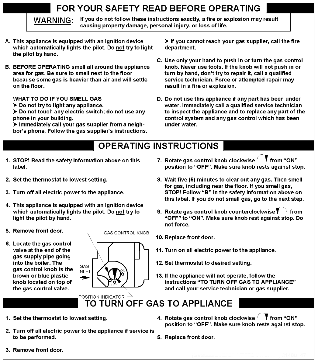
65
Figure 36: Operating Instructions
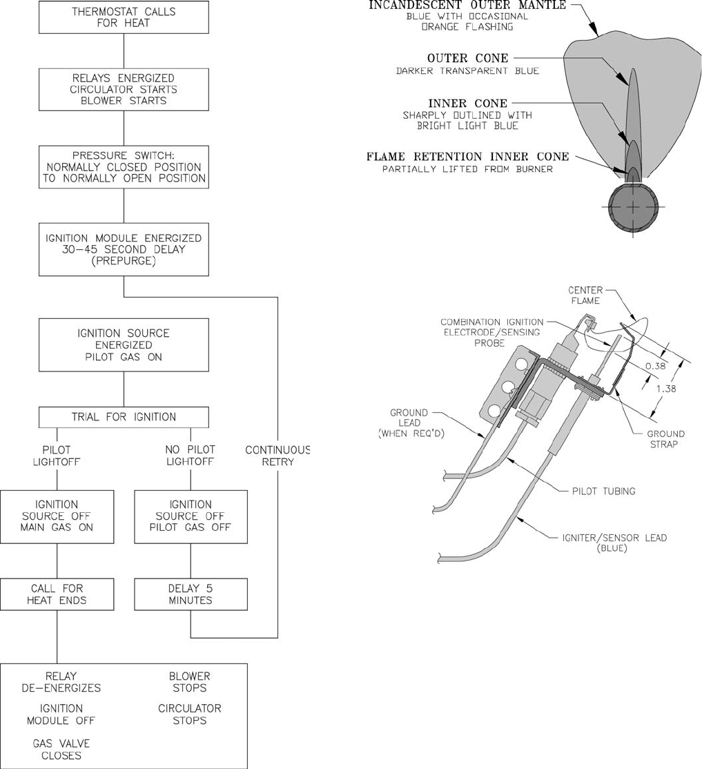
66
Figure 38: 1 Inch Main Burner fl ame
Figure 39: Pilot Burner Flame
Figure 37: Sequence of Operation
H. Follow Operating Instructions to place boiler in
operation. See Figure 36.
I. Sequence of Operation. See Figure 37. If boiler fails
to operate properly, see Troubleshooting Tree in Section
IX: Service.
J. Check pilot burner fl ame. See Figure 39. Flame
should be steady, medium hard blue enveloping 3/8 to
½ inch of sensing probe.
K. Check main burner fl ame. See Figures 38. Flame
should have clearly defi ned inner cone with no yellow
tipping. Orange-yellow streaks should not be confused
with true yellow tipping.
L. Check thermostat operation. Raise and lower
temperature setting to start and stop boiler operation.
M. Check ignition control module shut-off. Disconnect
pilot lead wires from gas valve. If burners do not
shutdown, determine cause of malfunction. Replace
necessary items and check operation.
N. Check low water cutoff (if so equipped).
1. Adjust thermostat to highest setting.
2. With boiler operating, open drain valve and slowly
drain boiler.
3. Main burners and pilot burner will extinguish and
blower will stop when water level drops below low
water cutoff probe. Verify limit, thermostat or other
controls have not shut off boiler.
4. Adjust thermostat to lowest setting. Refi ll boiler.
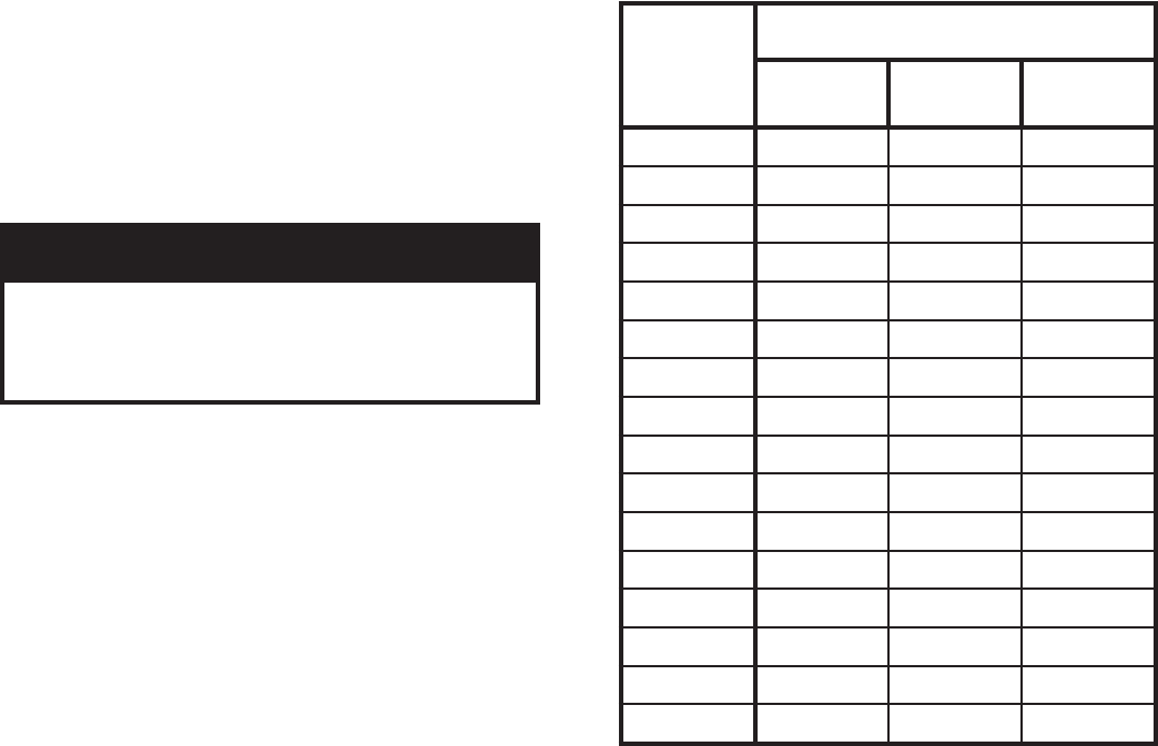
67
Table 10: Gas Flow Rate in Cubic Feet
Per Hour
O. Check limit.
1. Adjust thermostat to highest setting.
2. Observe temperature gauge. When temperature is
indicated, adjust limit to setting below observed
temperature. Main burners and pilot burner should
extinguish, and blower should stop.
3. Adjust limit to setting above observed temperature.
Ignition sequence should begin.
4. Adjust thermostat to lowest setting. Adjust limit to
desired setting.
P. Adjust gas input rate to boiler.
1. Adjust thermostat to highest setting.
2. Check manifold gas pressure. See Table 5 or rating
label located in the boiler’s vestibule compartment.
Adjust gas valve pressure regulator as necessary
(turn adjustment screw counterclockwise to
decrease manifold pressure, or clockwise to increase
manifold pressure). If pressure cannot be attained,
check gas valve inlet pressure. If less than minimum
indicated in Table 5 or boiler’s rating label, contact
gas supplier for assistance.
3. Clock gas meter for at least 30 seconds. Use Table
10 to determine gas fl ow rate in Cubic Feet per
Hour.
GNINRAW
lliwetartupnisagtsujdaylreporpoteruliaF
ehtfognirifrednurognirifrevonitluser
reliobefasnudnareporpmI.ecnailppa
.tluseryamnoitarepo
4. Determine Input Rate. Multiply gas fl ow rate by gas
heating value.
5. Compare measured input rate to input rate stated on
rating plate.
a. Boiler must not be over fi red. Reduce input rate
by decreasing manifold pressure. Do not reduce
more than 0.3 inch w.c. If boiler is still overfi red,
contact your Burnham distributor or Regional
Offi ce for replacement Gas Orifi ce.
b. Increase input rate if less than 98% of rating
plate input. Increase manifold gas pressure no
more than 0.3 inch w.c. If measured input rate is
still less than 98% of rated input:
i. Remove Main Burners per procedure in
Section IX: Service.
ii. Remove gas orifi ces. Drill one (1) drill size
larger (drill size is stamped on orifi ce, or see
Section X: Repair Parts).
iii. Reinstall gas orifi ces and main burners.
Measure input rate.
6. Recheck Main Burner Flame.
7. Return other gas-fi red appliances to previous
conditions of use.
Q. Review User’s Information Manual and system
operation with owner or operator.
sdnoceS
enOrof
noituloveR
laiDreteMsaGfoeziS
flaH-enO
.tF.uC
enO
.tF.uC
owT
.tF.uC
0306021042
2365311522
4335601212
6305001002
837459981
045409081
243468271
441428461
649387751
847357051
056327441
255396831
453376331
652346921
851326421
060306021
68
IX. Service
A. General. Inspection and service should be conducted
annually. Turn off electrical power and gas supply while
conducting service or maintenance. Follow instructions
TO TURN OFF GAS TO APPLIANCE. See Figure 37.
B. Low water cutoff (if so equipped).
Probe Type (Annual Service). Probe type LWCO
should be removed once a year, examined and
cleaned of any dirt accumulations to assure proper
operations. Do not attempt to repair mechanisms in the
fi eld. Complete replacement mechanisms, including
necessary gaskets and installation instructions, are
available from the manufacturer.
C. Vent/Air Intake System. Inspect for obstructions, soot
accumulation, proper support, and deterioration of pipe,
fi ttings, and joints.
1. Clean terminal screens. Terminals must be free of
obstruction, undamaged, with screens securely in
place.
2. Terminal and wall thimbles (if used) must be
weathertight.
3. Pipe must be full round shape, and show no damage
from impact or excessive temperature.
4. Pipe must be supported at minimum fi ve (5) foot
intervals and must not sag.
5. All vent joints must be secure and watertight.
6. All air intake joints must be secure and airtight.
Horizontal vent tee drain or vertical vent tee drain
(if used) must have minimum 6 inch trap and allow
condensate to fl ow freely. To Clean:
a. Disconnect drain tube from drain fi tting.
b. Flush drain tube with water. Fill trap with water.
c. Securely fasten drain tube to drain fi tting,
providing gas-tight and watertight seal.
7. If pipe must be disassembled for removal of
obstructions or resealing of joint, see Section III,
Paragraph C.
D. Boiler Flue Passages. Inspect for blockage or soot
accumulation.
1. Remove Main Burners. See Figure 42.
a. Remove front door.
b. Remove air intake box front door.
i. Remove sheet metal screws.
c. Disconnect pilot tubing and pilot lead wires at
the gas valve.
REGNAD
retawtohyrevdna,strapgnivom,yticirtceleegatlovhgih,sagelbammalfsesureliobsihT
ehttahtdnaffoeraseilppusrewopcirtcelednasagllatahterussA.erusserphgihrednu
.ecivresroylbmessasidynagnitpmettaerofebloocsierutarepmetretaw
ynagnitpmettaerofebffoerasehctiwstcennocsidlacirtcelednasevlavsagllatahterussA
.ecivresroylbmessasid
.reliobehtfoytinicivehtniriaehtnitneserpsisagfikrowecivresynatpmettatonoD
.ecivedlortnocynaht
iwrepmatroevomer,yfidomreveN
GNINRAW
ecivresdecneirepxednadelliksybderiaperdnadecivresebylnotsumreliobsihT
.snaicinhcet
.sledomlacitnedihtiwdecalperebtsumyeht,decalpereraslortnocynafI
snoitcesehtllanideniatnocsgninrawdnasnoitcurtsniehtllawollofdnadnatsrednu,daeR
.launamsihtfo
erussadnaseriwehtlebalylraelc,ecivresgniruddetcennocsideraseriwlacirtceleynafI
.ylreporpdetcennocereraseriwehttaht
.reliobsihtfotnenopmocrolortnocgnitareporoytefasynassapybrotuopmujreveN
ehtfoLLAnideniatnocsgninrawdnasnoitcurtsniehtllawollofdnadnatsrednu,daeR
.slaunamnoitcurtsnitnenopmoc
erofebylreporpgnitarepoerastnenopmocdnaslortnocgnitarepodnaytefasllatahterussA
.ecivresnikcabreliobehtgnicalp
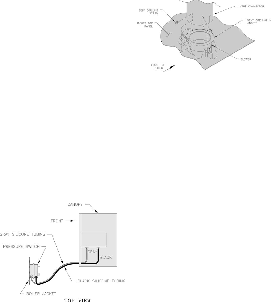
69
Figure 40: Silicone Tubing Assembly
Figure 41: Blower Vent Connector Assembly
d. Remove wires to Flame Roll-out Switch.
e. Remove air diffuser screen.
f. Remove Burner Access Panel.
g. Mark location of Main Burner with Pilot Bracket
on gas manifold.
h. Hold Main Burner on throat. Lift front of
burners to clear orifi ce. Burner which holds pilot
can be removed by lifting the burner adjacent to
its right fi rst.
2. Disconnect Vent Connector and Vent Pipe from
Blower Outlet
3. Remove Jacket Top Panel.
4. Disconnect the Black and Gary Silicone Tubing
from the Canopy.
5. Disconnect Wiring Harness from Blower Motor.
6. Remove Canopy/Blower Assembly.
a. Loosen the (4) screws from Canopy.
7. Remove Flue Gas Baffl es. Inspect Flue Gas Baffl es
for deterioration.
8. Inspect fl ue passages. Clean with fl ue brush. See
Figure 42.
9. Inspect heating surface in combustion chamber.
Clean with straight handle wire brush.
10. Install Flue Gas Baffl es.
11. Replace Canopy/Blower Assembly.
12. Connect Silicone Tubing between Pressure Fittings
on Canopy Assembly and Pressure Switch. Route
through bushings in Vestibule Panel . See Figure
40.
13. Install Jacket Top Rear Panel.
14. Connect Vent System. See Figure 41.
15. Connect Blower Motor Wiring Harness.
E. Main Burners and Firebox.
1. Vacuum fi rebox. Exercise care - do not damage base
insulation.
2. Clean main burners. Brush top of burners with soft
bristle brush. See Figure 42. Vacuum to remove any
dirt and lint.
3. Vacuum tip of pilot burner.
4. Check gas orifi ces for lint and dirt. Clean as
necessary.
5. Install main burners by reversing procedure to
remove burners.
a. Pilot burner must be installed in original
location. See Table 11.
b. Main burners must be properly secured in burner
tray slot at rear of fi rebox and over gas orifi ce.
See Figure 42.
c. Pilot gas supply and pilot lead wires must be
reconnected.
d. Burner access panel must be securely in place.
e. Reinstall air diffuser screen.
f. Reconnect Flame Roll-out wires.
g. Air Intake Box Front Door must be installed.
F. Check operation. Follow steps G through P from
Section VIII: System Start-up.
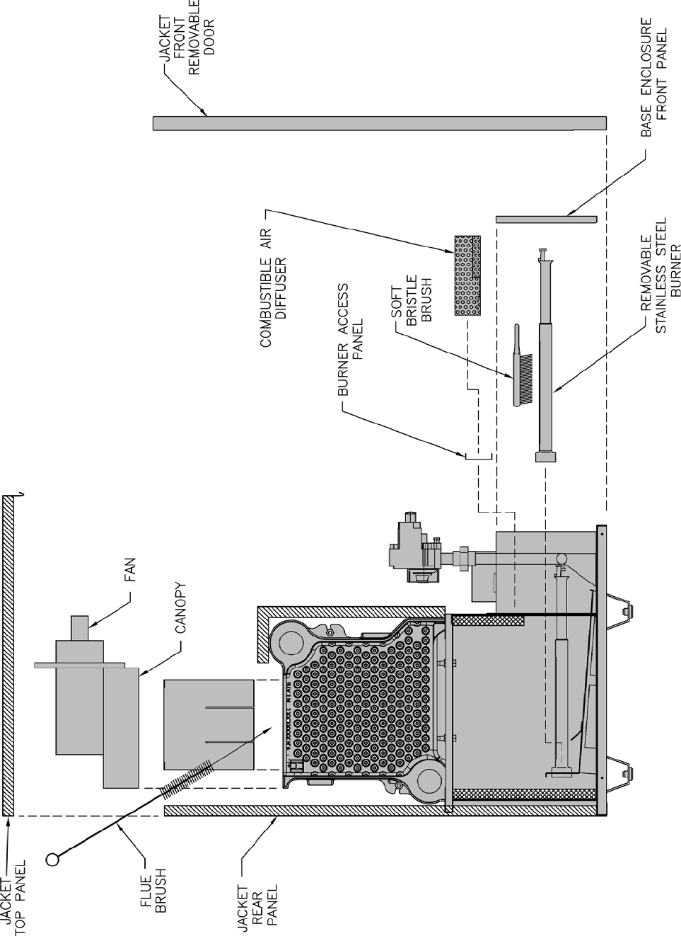
70
Figure 42: Flue and Burner Cleanout, 1” Burner
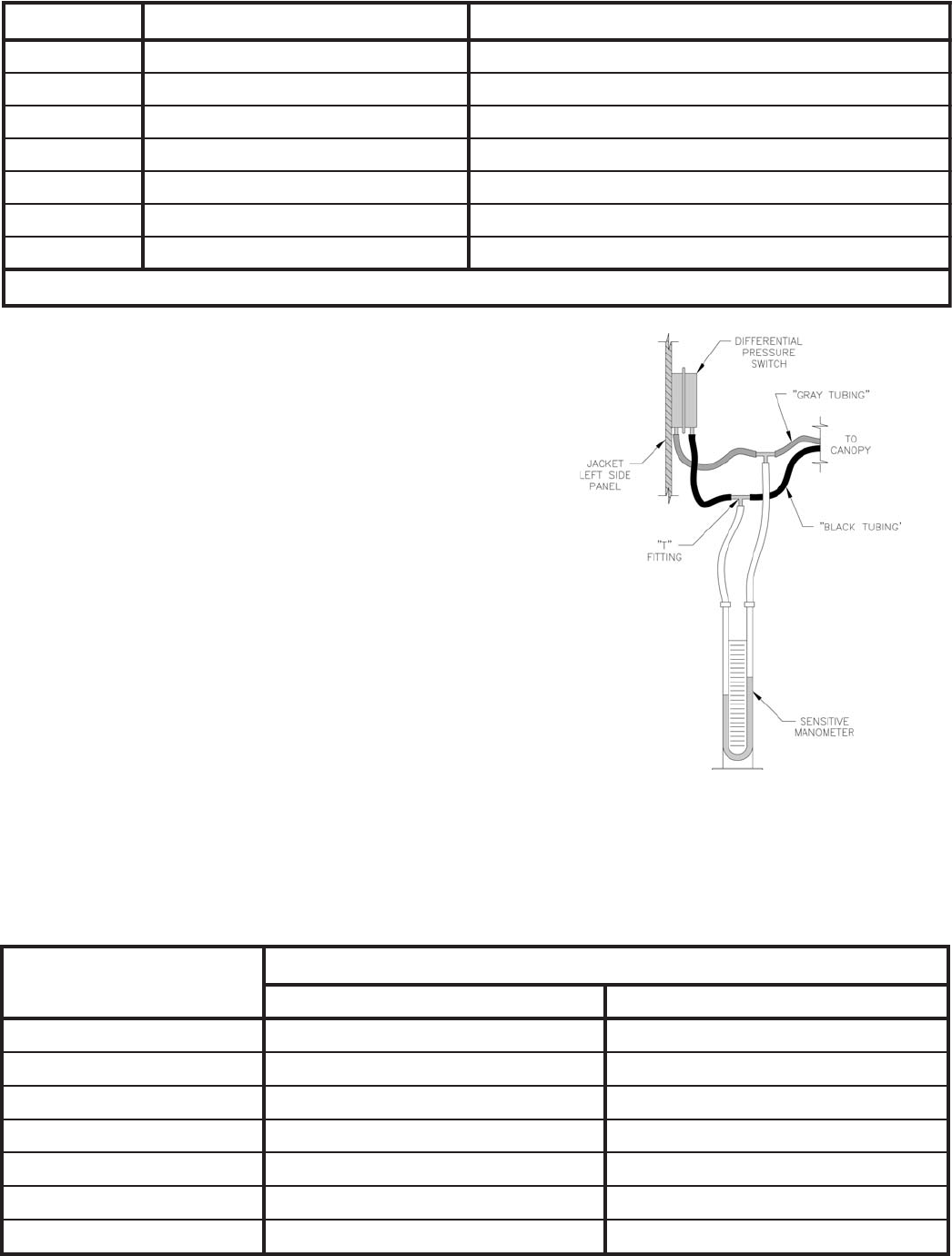
71
Table 11: Pilot Burner Location
G. Procedure for Measuring Differential Pressure (See
Figure 43).
1. With boiler off, remove Gray and Black Hoses at
differential pressure switch.
2. With tees and ¼ inch aluminum stubs, connect water
manometer as shown with additional tubing.
3. Start boiler and read Pressure on Manometer
when boiler water temperature reaches operating
temperature. Refer to Table 12 for minimum
readings.
NOTE: If switch drops-out before boiler reaches
temperature or if pressure differential readings are
below minimums shown in Table 12, check for
cracks in hose or contact your nearest Burnham
representative.
4. Stop boiler, remove manometer and reconnect hoses
to differential pressure switch. See Figures 40 and
43. Figure 43: Differential Pressure Measurement
ledoMrelioBtekcarBtoliPhtiwrenruBniaM *srenruBniaMneewteBdetacoLrenruBtoliP
3-GCS2 3&2
4-GCS3 4&3
5-GCS4 5&4
6-GCS5 6&5
7-GCS6 7&6
8-GCS7 8&7
9-GCS8 9&8
.reliobfotnorfmorfdeweivsathgirottfelderebmunsrenrub
niaM*
Table 12: Differential Pressure Switch Settings
ledoMrelioB erusserPlaitnereffiDmuminiM
.tF999,4otleveLaeSnoitavelE.tF000,01-000,5
3-GCS.c.w"23.1.c.w"08.
4-GCS.c.w"71.1.c.w"56.
5-GCS.c.w"71.1.c.w"56.
6-GCS.c.w"88..c.w"53.
7-GCS.c.w"08..c.w"03.
8-G
CS.c.w"88..c.w"53.
9-GCS.c.w"88..c.w"53.
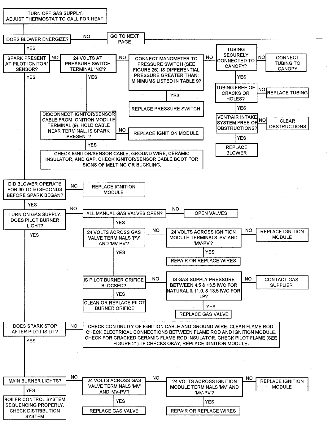
72
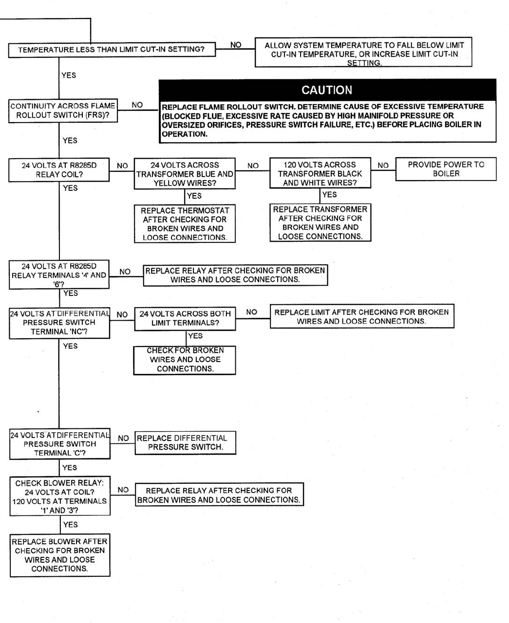
73
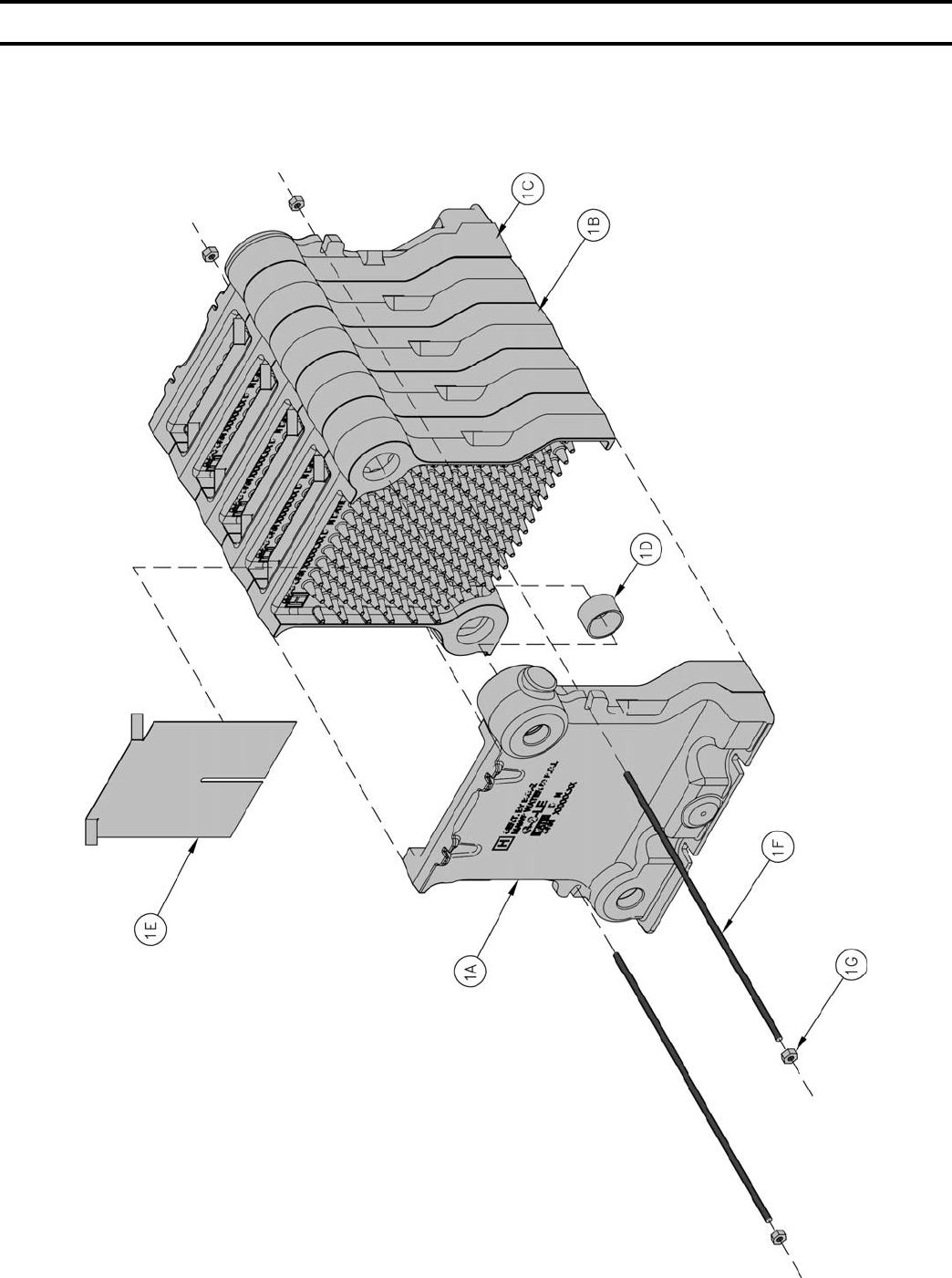
74
XI. Repair Parts
All SCG Repair Parts may be obtained through your local Burnham Wholesale distributor.
Should you require assistance in locating a Burnham distributor in your area, or have questions
regarding the availability of Burnham products or repair parts, please contact Burnham
Customer Service at (717) 481-8400 or Fax (717) 481-8408.

75
yeK
.oN noitpircseD rebmuNtraP]ytitnauQ[
3-GCS4-GCS5-GCS6-GCS7-GCS8-GCS9-GCS
YLBMESSAGNITSAC.1
1ylbmessAnoitceS13070716140707161507071616070715170707161807071619070716
A1noitceSdnEtfeL 10070717
B1noitceSretneC )1(
30070717
)2(
30070717
)3(
30070717
)4(
30070717
)5(
30070717
)6(
30070717
)7(
30070717
C1noitceSdnEthgiR 20070717
D13#,elppiNpilS )4(
900006608
)6(
900006608
)8(
900006608
)01(
900006608
)21(
900006608
)41(
900006608
)61(
900006608
E1elffaBsaGeulF )2(
20070117
)3(
20070117
)4(
20070117
)5(
20070117
)6(
20070117
)7(
20070117
)8(
20070117
F102-"¼,do
ReiT )2(
10-901001
)2(
50-801001
)2(
70-801001
)2(
31-801001
)2(
41-801001
)2(
51-801001
)2(
61-801001
G102-"¼,tuNxeH 70406808)4(
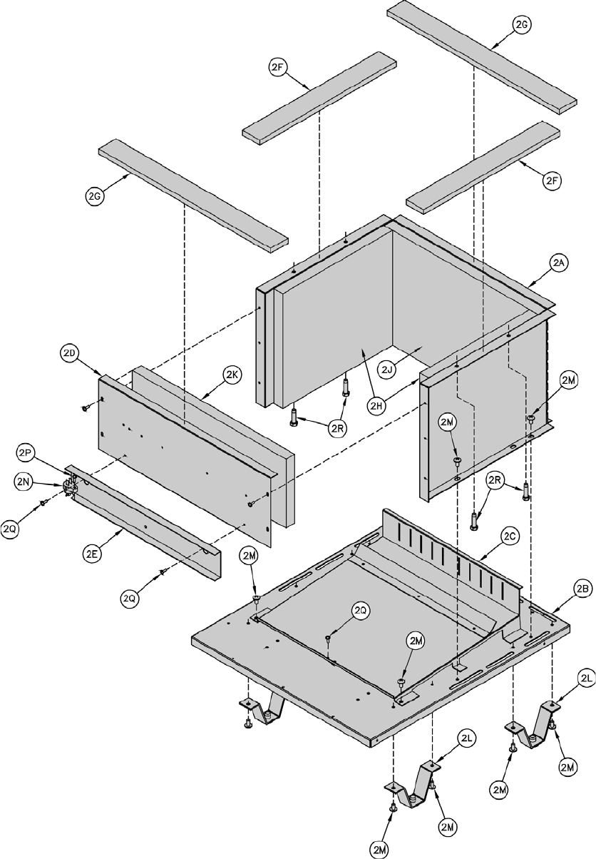
76
77
yeK
.oN noitpircseD
rebmuNtraP]ytitnauQ[
3-GCS4-GCS5-GCS6-GCS7-GCS8-GCS9-GCS
YLBMESSAESAB.2
A2repparWesaB13070817140708171507081716070817170708171807081719070817
B2yarTesaB230708172407081725070817260708172707
08172807081729070817
C2ylbmessAyarTrenruB13070816140708161507081616070816170708161807081619070816
D2lenaPtnorFesaB5
3070817540708175507081756070817570708175807081759070817
E2lenaPsseccArenruB630708176407081765070817660708176707081
76807081769070817
F2"2x"2/1teksaGtlefareC 2006026
G2"2x"2/1teksaGtlefareC 2006026
H2noitalusnIediSesaB 10070027)
2(
J2noitalusnIraeResaB13070027140700271507002716070027170700271807002719070027
K2noitalusnItnorFesaB2307002724070
0272507002726070027270700272807002729070027
L2ylbmessAgeLesaB 1006816)4(
M2"2/1x02-"4/1,wercSgnippaTfleS 0070680
8)81(
N2hctiwStuo-lloRemalF 44006108
P2"4/3x8#,wercSlateMteehS 03006808
Q2"8/3x23-01,wercSgnippaTfleS50706808)
5(0706808)6(0706808)7(
R2 ,paCxeHwercSgnippaTtfeS
"4/3x81-61/5 71706808)4(

78
79
yeK
.oN noitpircseD
rebmuNtraP]ytitnauQ[
3-GCS4-GCS5-GCS6-GCS7-GCS8-GCS9-GCS
YLBMESSAERUSOLCNEESAB.3
A3ylbmessAxoBriA23070816240708162507081626070816270708162807081629070816
B3rooDxoBriA430708174407081745070817460708
17470708174807081749070817
C3resuffiDriAnoitsubmoCA/N940708179507081796070817970708179807081799070817
D3etalPrevoCt
eksaGebuTtoliP 2006907
E3teksaGebuTtoliP 8306028
F3teksaGtroPnoitavresbO 9306028)2(
G3sneLtroPnoitavresbO 28062
08
H3reniateRsneLtroPnoitavresbO 9106817
J3"2/1x8#swercSlateMteehS 00006808)01(
K3"8/3x23-01,wercSgnippaTfleS5
0706808)81(50706808)22(
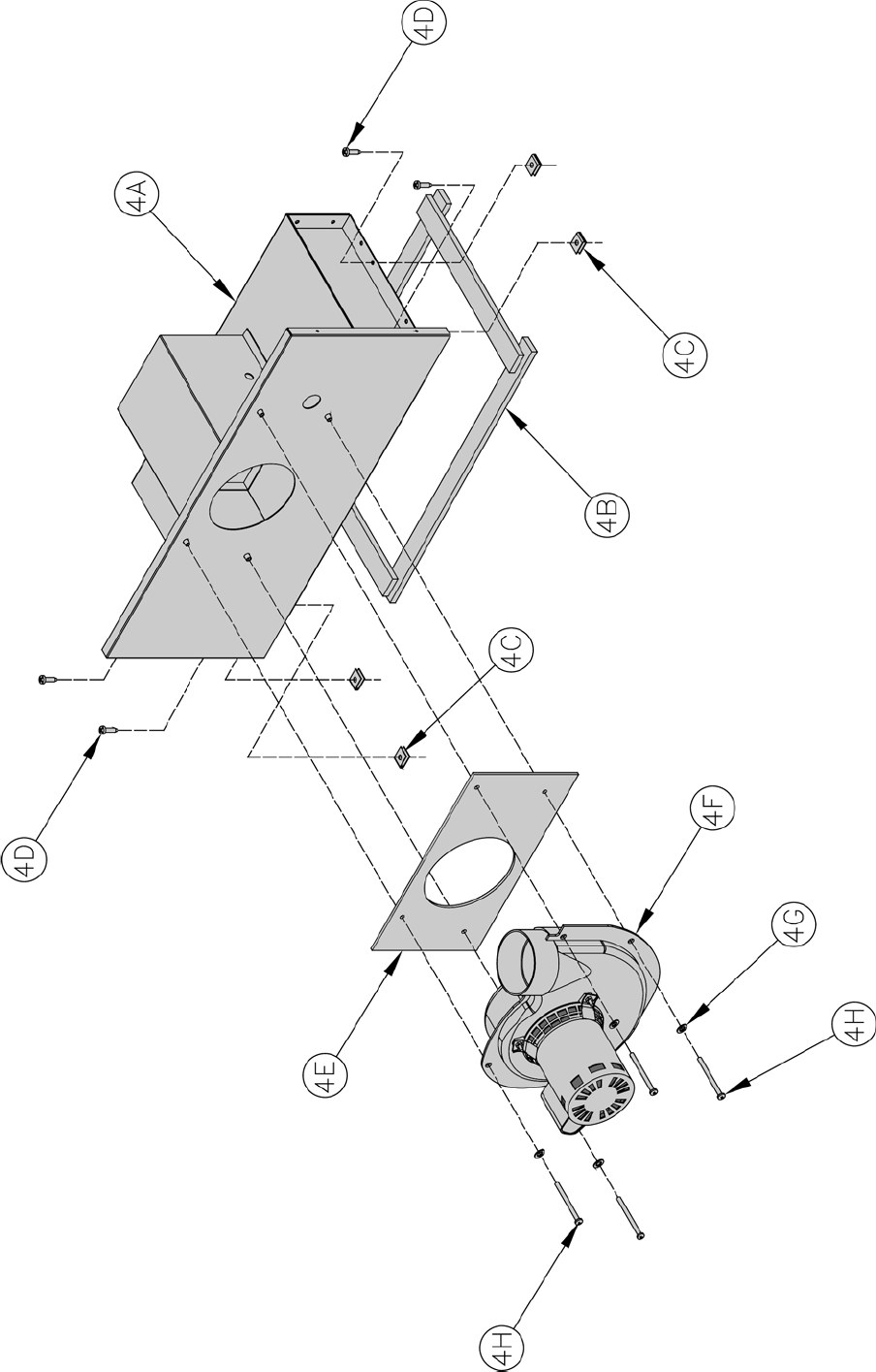
80

81
yeK
.oN noitpircseD
rebmuNtraP]ytitnauQ[
3-GCS4-GCS5-GCSCS6-GCS7-GCS-G8 CS-G9
YLBMESSAYPONAC/NAF.4
A4
leveLaeS-ylbmessAyponaC13070116140701161507011616070116170701161807011619070116
edutitlAhgiH-ylbmessAyponaC2
3070116240701162507011626070116270701162807011629070116
B4tlefareC 5006029
C4pilC-U 21516808)4(
D4"4/3x01#,wercSlat
eMteehS 31006808)4(
E4teksaGnaF 5806028
F4naF 21516118
G401#,rehsaWkcoL 63606808)4(
H4"2/1-2x42-01#,wercSenihcaM 2
89806808)4(
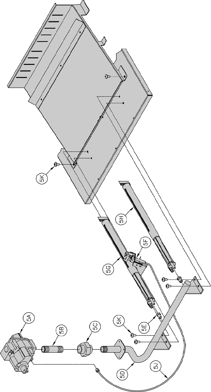
82
83
yeK
.oN noitpircseD
rebmuNtraP]ytitnauQ[
3-GCS4-GCS5-GCS
6-GCS7-GCS-GCS8 -GCS9
SEILBMESSARENRUB.5
A5
,)saGlarutaN(evlaVsaG
1711P4028RVllewyenoH 28206618A/N
,)saGlarutaN(evlaVsaG
6944P4038RVllewyenoH A/N38206
618
,)saGPL(evlaVsaG
5103C4028RVllewyenoH 64106618A/N
,)saGPL(evlaVsaG
0824P4038RVllewyenoH A/N18106618
B5
esol
CxTPN"½,elppiN 040006608A/N
esolCxTPN"¾,elppiNA/N220006608
C5
TPN"½,noinU 320406605A/N
TPN"¾,noinUA/N100406608
D5
d
lofinaMsaG13070228140702281507022816070228170702281807022819070228
dlofinaMsaG"¾
E5
74#saGlarutaN-secifirOrenru
B)4(
017228
)6(
017228
)8(
017228
)01(
017228
)21(
017228
)41(
017228
)61(
017228
mm02.1saGPL-secifirOrenruB )4(
2972
28
)6(
297228
)8(
297228
)01(
297228
)21(
297228
)41(
297228
)61(
297228
F5
saGlarutaN-ylbmessAtoliP 3616328
saGPL-yl
bmessAtoliP 4616328
G5renruBtoliP 10-741001
H5renruBniaM )3(
10-641001
)5(
10-641001
)7(
10-641001
)9(
10-641001
)11
(
10-641001
)31(
10-641001
)51(
10-641001
J5gnibuTtoliP 2216328
K5"2/1x02-4/1,wercSgnippaTfleS 00706808)6(
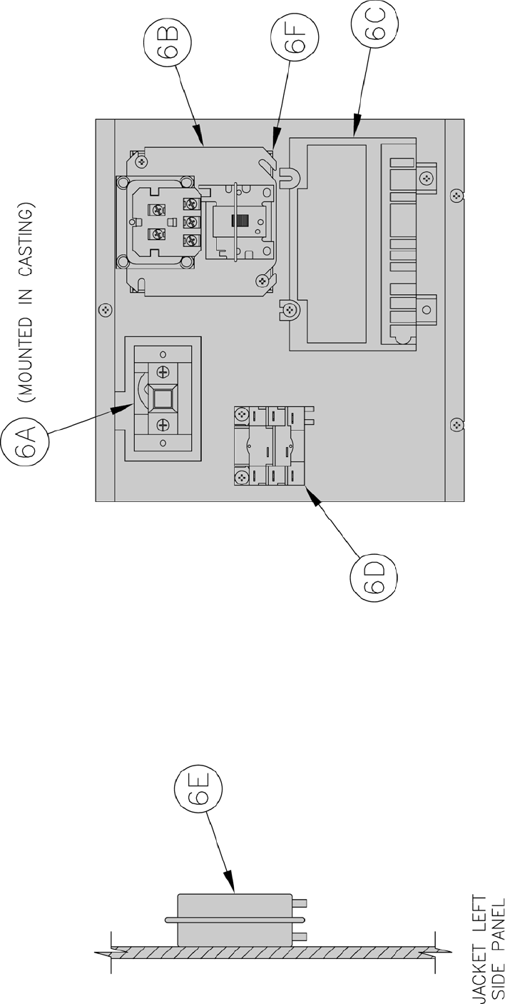
84

85
yeK
.oN noitpircseD
rebmuNtraP]ytitnauQ[
3-GCS4-GCS5-GCS6-GCS7-GCS8-GCS9-GCS
YLBMESSALENAPLORTNOC.6
A6D0804LllewyenoH,timiL 65106108
B6D5828RllewyenoH,yaleR/remrofsnarT U55106108
C6 llewyenoH,eludoMnoitingI
70
01E0768S 80106108
D66001U2228RllewyenoH,yaleRrewolB U69006108
E6
hctiwSerusserPlaitnereffiD
'9994-'0leveLaeS 2670610816706108067061089570610806706108
'000,01-'0005-edutitlAhgiH9570610836706108467061085670610846706108
F6xoB
noitcnuJ 9526318
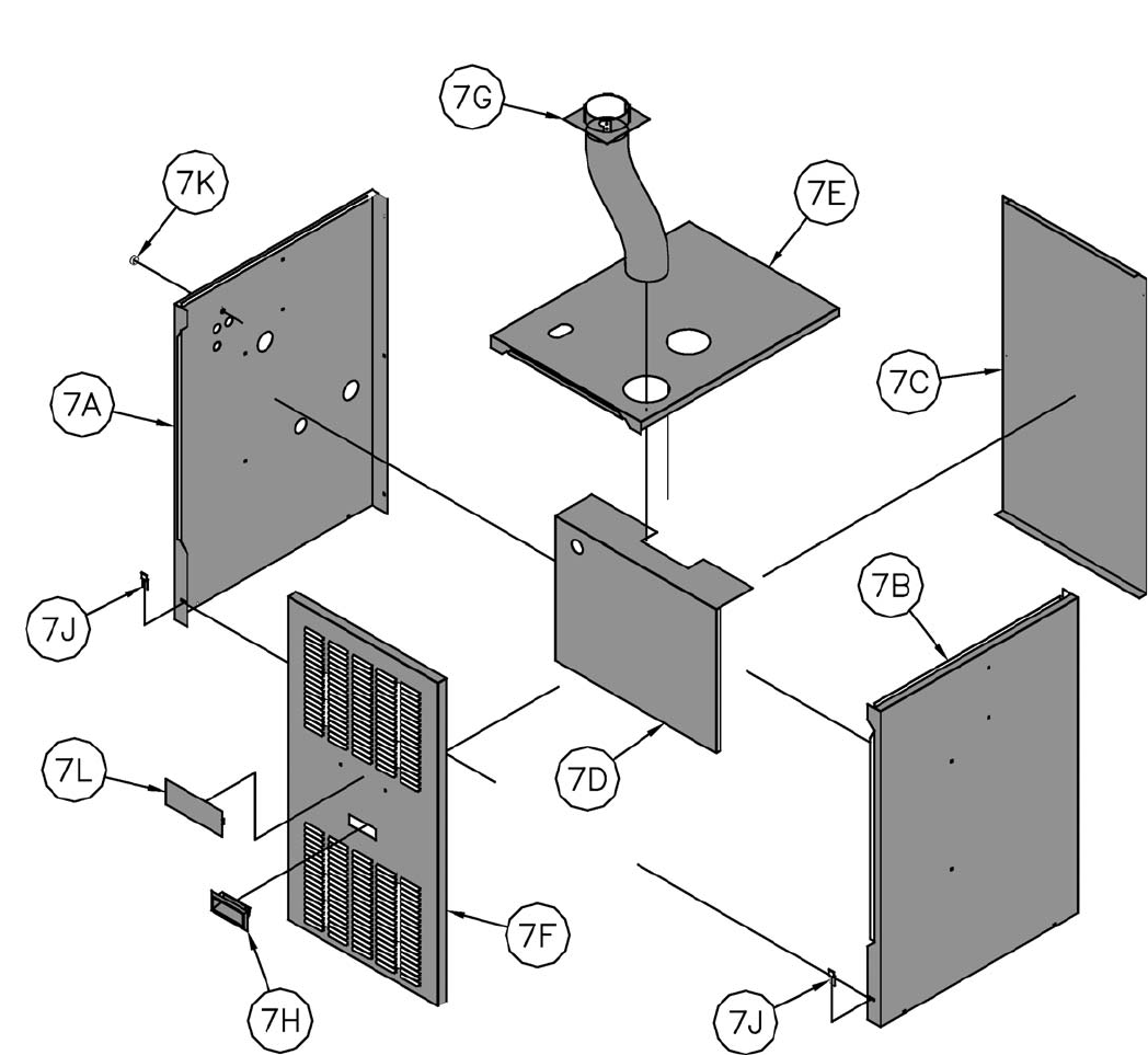
86
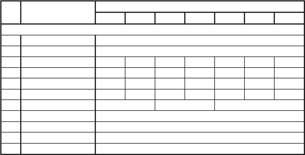
87
yeK
.oN noitpircseD
rebmuNtraP]ytitnauQ[
3-GCS4-GCS5-GCS6-GCS7-GCS8-GCS9-GCS
STRAPTEKCAJ.7
A7lenaPediStfeLtekcaJ 20070406
B7lenaPediSthgiRtekcaJ 10070406
C7lenaPraeR330704063407040635070406360704063707040
63807040639070406
D7lenaPelubitseV43070406440704064507040646070406470704064807040649070406
E7lenaPpoT230704062407040
6257040626070406270704062807040629070406
F7rooDtnorF13070407140704071507040716070407170704071807040719070407
G7ylbmes
sAralloCekatnIriA300704064007040650070406
H7eldnaH 4816508
J7pilCrooD 1291407)2(
K7gnihsuB 8406318
L7ogoLmahnruB 990
06418
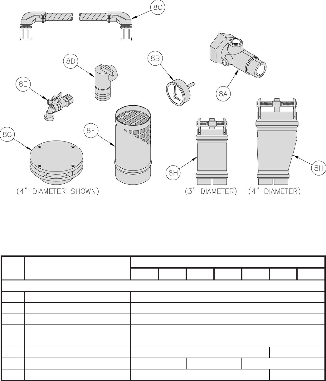
88
yeK
.oN noitpircseD
rebmuNtraP]ytitnauQ[
3-GCS4-GCS5-GCS6-GCS7-GCS8-GCS9-GCS
8. NOTRACSTRAPSUOENALLECSIM
A8dlofinaMretaW 10070608
B8eguaGerusserP/erutarepmeT 9616508
C8ssenraHgniriWrotalucriC 1070316
D8evlaVfeileRyte
faS 36306618
E8evlaVniarDrelioB 160306608
F8lanimreTtneV 10701182070118
G8lanimreTekatnIriA540611644061163606116
H8r
otcennoCtneV 30701184070118

89
noitamrofnIytefaStcudorPtnatropmI
tcudorPrebiFcimareCyrotcarfeR
Warning:
This product contains refractory ceramic fi bers (RCF). RCF has been classifi ed as a
possible human carcinogen. After this product is fi red, RCF may, when exposed to
extremely high temperature (>1800F), change into a known human carcinogen. When
disturbed as a result of servicing or repair, RCF becomes airborne and, if inhaled, may
be hazardous to your health.
AVOID Breathing Fiber Particulates and Dust
Precautionary Measures:
Do not remove or replace previously fi red RCF (combustion chamber insulation, target
walls, canopy gasket, fl ue cover gasket, etc.) or attempt any service or repair work
involving RCF without wearing the following protective gear:
1. A National Institute for Occupational Safety and Health (NIOSH) approved
respirator
2. Long sleeved, loose fi tting clothing
3. Gloves
4. Eye Protection
• Take steps to assure adequate ventilation.
• Wash all exposed body areas gently with soap and water after contact.
• Wash work clothes separately from other laundry and rinse washing machine
after use to avoid contaminating other clothes.
• Discard used RCF components by sealing in an air tight plastic bag.
First Aid Procedures:
• If contact with eyes: Flush with water for at least 15 minutes. Seek
immediate medical attention if irritation persists.
• If contact with skin: Wash affected area gently with soap and water. Seek
immediate medical attention if irritation persists.
• If breathing diffi culty develops: Leave the area and move to a location with
clean fresh air. Seek immediate medical attention if breathing diffi culties
persist.
• Ingestion: Do not induce vomiting. Drink plenty of water. Seek immediate
medical attention.

90
SERVICE RECORD
DATE SERVICE PERFORMED

91
SERVICE RECORD
DATE SERVICE PERFORMED
water boiler for its intended purposes and its maintenance
accordance with U. S. Boiler Co., Inc. recommendations and
hydronics industry standards. These warranties will be inapplicable if
the residential grade water boiler is used or operated over its rated
capacity, is subjected to unauthorized modification, or is damaged as
a result of being otherwise improperly operated or serviced including,
but not limited to, damage from any of the following: operation with
insufficient water, allowing the boiler to freeze, subjecting the boiler
to flood conditions, and operation with unapproved water or fuel
additives which cause deposits or corrosion.
5. Removal and Installation: These warranties do not cover expenses of
removal or reinstallation. The owner is responsible for the cost of
removing and reinstalling any defective part and its replacements
and all labor and material connected therewith.
6. Exclusive Remedy: U.S. Boiler Co., Inc. obligation for any breach of
these warranties is limited to the repair or replacement of its parts in
accordance with the terms and conditions of these warranties.
7. Limitation of Damages: Under no circumstances shall U.S. Boiler
Co., Inc. be liable for incidental, indirect, special or consequential
damages of any kind whatsoever under these warranties, including,
but not limited to, injury or damage to persons or property and
damages for loss of use, inconvenience or loss of time. U.S. Boiler
Co., Inc. liability under these warranties shall under no circumstances
exceed the purchase price paid by the owner for the residential grade
water boiler involved. Some states do not allow the exclusion or
limitation of incidental or consequential damages, so the above
limitation or exclusion may not apply to you.
8. Limitation of Warranties: These warranties set forth the entire
obligation of U.S. Boiler Co., Inc. with respect to any defect in a
residential grade water boiler and U.S. Boiler Co., Inc. shall have no
express obligations, responsibilities or liabilities of any kind
whatsoever other than those set forth herein. These warranties are
given in lieu of all other express warranties.
ALL APPLICABLE IMPLIED WARRANTIES, IF ANY, INCLUDING
ANY WARRANTY OF MERCHANTABILITY OR FITNESS FOR A
PARTICULAR PURPOSE ARE EXPRESSLY LIMITED IN DURATION
TO A PERIOD OF ONE YEAR EXCEPT THAT IMPLIED
WARRANTIES, IF ANY, APPLICABLE TO THE HEAT EXCHANGER IN
A RESIDENTIAL GRADE WATER BOILER SHALL EXTEND TO THE
ORIGINAL OWNER FOR THE LIFETIME OF THE ORIGINAL OWNER
AT THE ORIGINAL PLACE OF INSTALLATION. SOME STATES DO
NO ALLOW LIMITATION ON HOW LONG AN IMPLIED WARRANTY
LASTS, SO THE ABOVE LIMITATION MAY NOT APPLY TO YOU.
PROCEDURE FOR OBTAINING WARRANTY SERVICE
In order to assure prompt warranty service, the owner is requested to
complete and mail the attached Warranty Card within ten days after the
installation of the boiler, although failure to comply with this request will
not void the owner’s rights under these warranties.
Upon discovery of a condition believed to be related to a defect in
material or workmanship covered by these warranties, the owner should
notify the installer, who will in turn notify the distributor. If this action is
not possible or does not produce a prompt response, the owner should
write to U.S. Boiler Co., Inc., Burnham Hydronics, at P.O. Box 3079,
Lancaster, PA 17604, giving full particulars in support of the claim.
The owner is required to make available for inspection by U.S. Boiler
Co., Inc. or its representative the parts claimed to be defective and, if
requested by U.S. Boiler Co., Inc. to ship these parts prepaid to U.S.
Boiler Co., Inc. at the above address for inspection or repair. In
addition, the owner agrees to make all reasonable efforts to settle any
disagreement arising in connection with a claim before resorting to legal
remedies in the courts.
THIS WARRANTY GIVES YOU SPECIFIC LEGAL RIGHTS AND
YOU MAY ALSO HAVE OTHER RIGHTS WHICH VARY FROM STATE
TO STATE.
Limited Warranty
FOR RESIDENTIAL CAST IRON WATER BOILERS
03/03
Subject to the terms and conditions set forth below, U.S. Boiler™
Co., Inc. Lancaster, Pennsylvania hereby extends the following limited
warranties to the original owner of a residential grade water boiler
manufactured and shipped on or after July 1,1991:
ONE YEAR LIMITED WARRANTY
ON RESIDENTIAL GRADE WATER BOILERS
U.S. Boiler Co., Inc. warrants to the original owner that its residential
grade water boilers comply at the time of manufacture with recognized
hydronic industry standards and requirements then in effect and will be
free of defects in material and workmanship under normal usage for a
period of one year from the date of original installation. If any part of a
water boiler is found to be defective in material or workmanship during
this one year period, U.S. Boiler Co., Inc. will, at its option, repair or
replace the defective part.
LIFETIME LIMITED WARRANTY ON HEAT EXCHANGER
U.S. Boiler Co., Inc. warrants to the original owner that the heat
exchanger of its residential grade water boilers will remain free from
defects in material and workmanship under normal usage for the lifetime
of the original owner at the original place of installation. If a claim is
made under this warranty during the first ten years from the date of
original installation, U.S. Boiler Co., Inc. will, at its option, repair or
replace the heat exchanger. If a claim is made under this warranty after
the expiration of ten years from the date of original installation, U.S.
Boiler Co., Inc. will, at its option and upon payment of the pro-rated
service charge set forth below, repair or replace the heat exchanger.
The service charge applicable to a heat exchanger warranty claim is
based upon the number of years the heat exchanger has been in
service and will be determined as a percentage of the retail price of the
heat exchanger model involved at the time the warranty claim is made
as follows:
NOTE: If the heat exchanger model involved is no longer available due
to product obsolescence or redesign, the value used to establish the
retail price will be the published price as shown in the Burnham
Hydronics Repair Parts Price Sheet where the heat exchanger last
appeared or the current retail price of the then nearest equivalent heat
exchanger.
ADDITIONAL TERMS AND CONDITIONS
1. Applicability: The limited warranties set forth above are extended
only to the original owner at the original place of installation within the
United States and Canada. These warranties are applicable only to
water boilers designated as residential grade by U.S. Boiler Co., Inc.
and installed in a single or two-family residence and do not apply to
steam boilers of any kind or to commercial grade boilers.
2. Components Manufactured by Others: Upon expiration of the one
year limited warranty on residential grade water boilers, all boiler
components manufactured by others but furnished by U.S. Boiler
Co., Inc. (such as oil burner, circulator and controls) will be subject
only to the manufacturer’s warranty, if any.
3. Proper Installation: The warranties extended by U.S. Boiler Co., Inc.
are conditioned upon the installation of the residential grade water
boiler in strict compliance with U.S. Boiler Co., Inc. installation
instructions. U. S. Boiler Co., Inc. specifically disclaims liability of any
kind caused by or relating to improper installation.
4. Proper Use and Maintenance: The warranties extended by U.S.
Boiler Co., Inc. conditioned upon the use of the residential grade
sraeY
ecivreSnI 01-111213141516171
egrahCecivreS
fo%sa
ecirPliateR
oN
egrahC 5015102520353
sraeY
ecivreSnI 81910212223242dna52
evoba
egrahCecivreS
fo%sa
ecirPliateR
0454055506560757
