Bury and Co KG BURYBCM001 Bluetooth Module for Audio and Data Transfer User Manual 321311
Bury GmbH & Co KG Bluetooth Module for Audio and Data Transfer 321311
Users Manual

BURY GMBH & CO. KG
ROBERT-KOCH-STRASSE 1-7
32584 LÖHNE
BURY GMBH & CO. KG • ROBERT-KOCH-STR. 1-7 • 32584 LÖHNE
FB QS / Stand 02.03 / Rev. 02
THB
“Bluetooth Comfort Module”
BCM001
OEM User
Operation Manual
Date of preparation: April 2003

BURY GMBH & CO. KG
ROBERT-KOCH-STRASSE 1-7
32584 LÖHNE
BURY GMBH & CO. KG • ROBERT-KOCH-STR. 1-7 • 32584 LÖHNE
FB QS / Stand 02.03 / Rev. 02
General Notes:
This document is issued by Bury GmbH & Co.KG (hereinafter called Bury) in confidence, and is
not to be reproduced in whole or in part without the prior written permission of Bury. The
information contained herein is the property of Bury and is to be used only for the purpose for
which it is submitted and is not to be released in whole or in part without the prior written
permission of Bury.
Important
1. This module is intended to use for wireles audio and data transfer for OEM integration in
final products.
2. When integrating the THB “Bluetooth Comfort Module” into a final product, the following
information must be considered:
All products containing the module must be labelled. The label must be affixed on an
exterior surface of the end product such that it will be visible upon inspection in
compliance with the modular approval guidelines developed by the FCC.
The label must state “This device contains FCC ID QZ9-BURYBCM001”
In addition, the user manual for the end product must contain the following information:
"This device complies with Part 15 of the FCC Rules. Operation is subject to the following
two conditions:
(1) this device may not cause harmful interference, and
(2) this device must accept any interference received,
including interference that may cause undesired operation."
3. Take care of electrostatic discharge while handling the module. This may destroy the
module.
4. Don´t place the module in a metal housing. This may reduce the operating distance.
5. This device and its antenna must not be co-located or operating in conjunction with any
other antenna or transmitter.
6. For using antennas not mounted on the module see related document “Bluetooth Comfort
Module Antenna Specification “. Take only the specified antennas, otherwise loss of FCC
and Bluetooth Approval will result.
7. The users manual or instruction manual for an intentional or unintentional radiator shall
caution the user that changes or modifications not expressly approved by the party
responsible for compliance could void the user's authority to operate the equipment.
8. The OEM Manufacturer must not describe to the end user how to install or deinstall the
Bluetooth Comfort Module.
BURY GMBH & CO. KG
ROBERT-KOCH-STRASSE 1-7
32584 LÖHNE
BURY GMBH & CO. KG • ROBERT-KOCH-STR. 1-7 • 32584 LÖHNE
FB QS / Stand 02.03 / Rev. 02
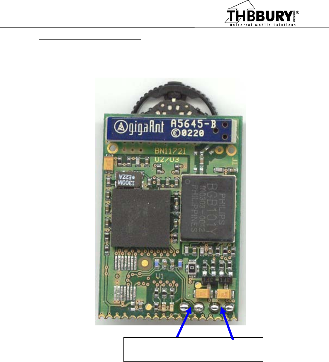
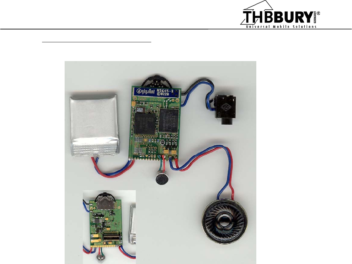
Bluetooth module – Top side
electret
microphone + --- speaker --- +
Picture 1.
BURY GMBH & CO. KG
ROBERT-KOCH-STRASSE 1-7
32584 LÖHNE
BURY GMBH & CO. KG • ROBERT-KOCH-STR. 1-7 • 32584 LÖHNE
FB QS / Stand 02.03 / Rev. 02
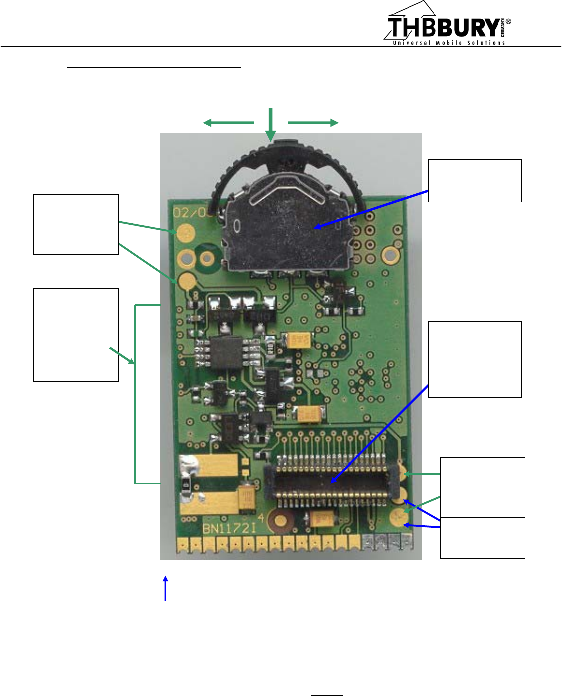
Bluetooth module – Bottom side
J1 - 18 side contacts:
18 – Speaker + 12 – Volume - 6 – Voice IN +
17 – Speaker - 11 – Microphone mute 5 – Voice IN -
16 – Ground (supply - ) 10 – MFB/GPIO 4 – Serial Data Receive
15 – LED Green 9 – REF_CLK 3 – Serial Data Transmit
14 – LED Red 8 - VMIC 2 – Supply voltage +
13 – Volume + 7 - RESET 1 – Ground (supply - )
Note: For detailed pinout description of J1 see Table 2.
J4
charging --
voltage +
J3
+ Battery
-- voltage
Thermistor
connection
PRESS
volume DOWN volume UP
3-functional
SWITCH
J2
40 contacts
connector optionally
mounted
charger
& power
supply
regulator
components
18 - - 15 - - 12 - - 9 - - 6 - - 3 - -
Picture 2.

BURY GMBH & CO. KG
ROBERT-KOCH-STRASSE 1-7
32584 LÖHNE
BURY GMBH & CO. KG • ROBERT-KOCH-STR. 1-7 • 32584 LÖHNE
FB QS / Stand 02.03 / Rev. 02
1. USAGE SCENARIO:
Turn On
Turn Off
Answer a call
Call Reject
volume up/down
Button functions
LED signals
BURY GMBH & CO. KG
ROBERT-KOCH-STRASSE 1-7
32584 LÖHNE
BURY GMBH & CO. KG • ROBERT-KOCH-STR. 1-7 • 32584 LÖHNE
FB QS / Stand 02.03 / Rev. 02
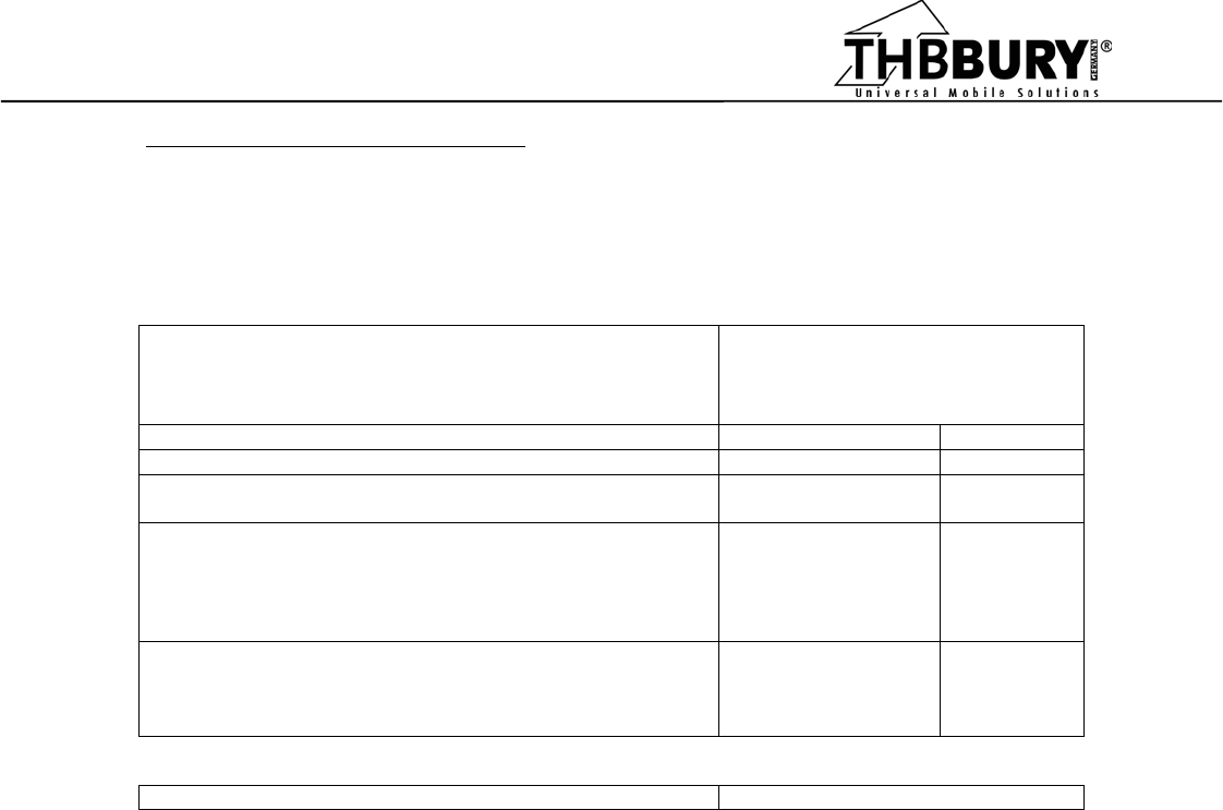
2. ELECTRICAL DATA & CHARACTERISTICS:
Table 1. “Bluetooth Comfort Module” Electrical Data:
PARAMETER
VALUE
Charging voltage - DC 4,8 ÷ 5,8 V
Absolute maximum charging voltage 6,0 V
Main power supply (onboard regulator)
Regulator maximum current
3,0
180
V
mA
Battery voltage
Minimum operational battery voltage
typ. 3,7
max. 4,2
min. 3,2
V
V
V
Absolute maximum supply voltage
NOTE! Supply voltage higher than 6 Volts - only
if battery charger and its output capacitor
are not mounted !!!
16,0 V
Battery type Lithium Polymer
Supply options:
There is possibility to supply module from battery or from any other external power supply,
regarding maximum input voltage of voltage regulator and other components.
3. THREE options for connecting external signals & power supply:
3.1. PCB pads shown in Picture 1. and Picture 2.
3.2. 40 contacts connector on bottom side shown in Picture 2.
3.3. Side contacts on bottom of Picture 2.
4. TWO options for operation:
4.1. Through 3-functional switch and I/O lines mentioned in points 3.2. and 3.3.
4.2. Through AT commands
BURY GMBH & CO. KG
ROBERT-KOCH-STRASSE 1-7
32584 LÖHNE
BURY GMBH & CO. KG • ROBERT-KOCH-STR. 1-7 • 32584 LÖHNE
FB QS / Stand 02.03 / Rev. 02
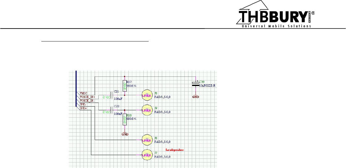
5. Microphone & speaker connections.
Picture 3. Part of Bluetooth Comfort Module schematic - audio connections
There are 3 options for connecting audio signals:
Audio input:
- electret microphone connections to pads J8, J9 on top of board
- VOICE_IN – ( J1 – 5 ) & VOICE_IN + ( J1 – 6 ) audio direct input
and also microphone power supply VMIC (J1 – 8 ) - if needed
- J2 connector
Audio output:
- loudspeaker connections to pads J6, J7 on top of board
- J1–18 & J1–17 - side contacts
- J2 connector
BURY GMBH & CO. KG
ROBERT-KOCH-STRASSE 1-7
32584 LÖHNE
BURY GMBH & CO. KG • ROBERT-KOCH-STR. 1-7 • 32584 LÖHNE
FB QS / Stand 02.03 / Rev. 02
Picture 4. Sample connections – headset application.
6. Battery & charger:
Charging voltage:
External, 5V charging voltage is delivered to J4 on bottom side of PCB.
Maximum current depends on used battery & onboard charger configuration.
Battery:
Any Lithium-polymer battery may be connected to J3 on bottom side of PCB.
External resistor 10K or NTC overheating protecting thermistor must be connected
to ground on J3 to enable charger functionality.
For battery charging current setting information – please contact THB or read Microchip
MCP73828 datasheet or Application notes..
TOP
BOTTOM

BURY GMBH & CO. KG
ROBERT-KOCH-STRASSE 1-7
32584 LÖHNE
BURY GMBH & CO. KG • ROBERT-KOCH-STR. 1-7 • 32584 LÖHNE
FB QS / Stand 02.03 / Rev. 02
Table 2. J1 - Pinout description:
1 Ground
2 Power supply, usually from lithium polymer battery.
3 Module RS232 TX signal. Default speed 19200 bps.
4 Module RS232 RX signal. Default speed 19200 bps.
5 Audio input signal -
6 Audio input signal +
7 Module Hardware Reset Input. Reset Active low.
8 VMIC – electret microphone 2 Volts supply voltage. Low voltage level when microphone Mute is active.
Reference voltage for module tuning.
9 REF_CLK – 13 MHz reference clock signal. Used for module tuning procedure.
10 MFB/GPIO – Active low. The same functionality as 3 functional switch press.
11 MUTE – Microphone muting
12 Volume - - Speaker volume decrease.
13 Volume + - Speaker volume increase.
14 RED LED - Output signal active to positive voltage.
15 GREEN LED - Output signal active to negative voltage.
16 Ground
17 Speaker - Output to speaker, headphones etc.
18 Speaker + Output to speaker, headphones etc.
Addendum. J2 signals description.
J2 connector is designed specifically for connecting module to ANY other PCB, with minimum occupied space
on host system. Connector provides access to all signals needed for development or ‘real life’ application.
For detailed connector’s signals and functionality description please contact THB.