Bushnell Deep Space Series 78 9519 Users Manual
Bushnell-Deep-Space-789519-Owner-S-Manual bushnell-deep-space-789519-owner-s-manual
Bushnell-Deep-Space-789520-Owner-S-Manual bushnell-deep-space-789520-owner-s-manual
78-9519 to the manual 3f8d87d3-7f61-46a8-8e5e-99610ecf7f85
2015-01-21
: Bushnell Bushnell-Deep-Space-Series-78-9519-Users-Manual-352980 bushnell-deep-space-series-78-9519-users-manual-352980 bushnell pdf
Open the PDF directly: View PDF ![]() .
.
Page Count: 5
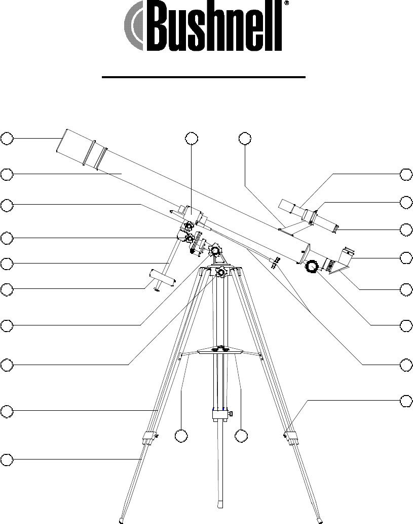
DEEP SPACE SERIES
675 x 60 Refractor Telescope
Model 78-9519
22 21
1. 60mm Objective Lens
2. Telescope Main Tube
3. Declination Lock Knob
4. Right Ascension Lock Knob
5. Counterweight Shaft
6. Counterweight
7. Altitude Lock Knob
8. Azimuth Lock Knob
9. Tripod Leg
10. Tripod Leg Middle Section
11. Accessory Tray Brace
12. Accessory Tray
13. Tripod Leg - Lock Screws
14. Fine Adjustment Cable & Knob
15. Rack & Pinion Focusing Mechani
16. Diagonal Mirror
17. Eyepiece
18. Finderscope Focus Adjustment
19. Finderscope Adjustment Screws(
20. Finderscope
21. Finderscope Mount
22. Equatorial Mount
10
9
8
7
6
5
4
3
1
2
11 12
13
14
15
16
17
18
19
20
STANDARD EQUIPMENT
• Complete Main Telescope Assembly
• Full Length Variable-Height Hardwood Tripod
• Equatorial Mount with counterweight and flexible adjustment cables
• 4mm, 12mm, 20mm focal length - Eyepieces
• Diagonal Mirror, 3x Barlow Lens, Erecting Lens
• 5 x 24 Finderscope w/focus adjustment, Accessory Tray
• Hardware Pack:
Tripod leg: 3-2_”bolts, 6-11/16 washers and 3-wingnuts
Accessory tray: 3-_” bolts, 6-_” washers and 3-wingnuts
Tripod Leg Lock Screws: 3 pc.
Fine Adjustment Knobs: 2 pc.
TELESCOPE ASSEMBLY
1. Remove telescope from carton and identify all components. READ THROUGH ASSEMBLY
INSTRUCTIONS BEFORE YOU ASSEMBLE YOUR TELESCOPE
2. Set-Up Tripod, Mount and Accessory Tray
• Select one Tripod Leg (9) and extend the Tripod Leg Middle Section (10). Using Tripod Leg Lock Screws
(13) included in the hardware pack, insert the Tripod Leg Lock Screw into the lower brackets on the
Tripod Leg (9). Tighten the Tripod Leg Lock Screws so that the Middle Section is securely in place.
Repeat on remaining two legs.
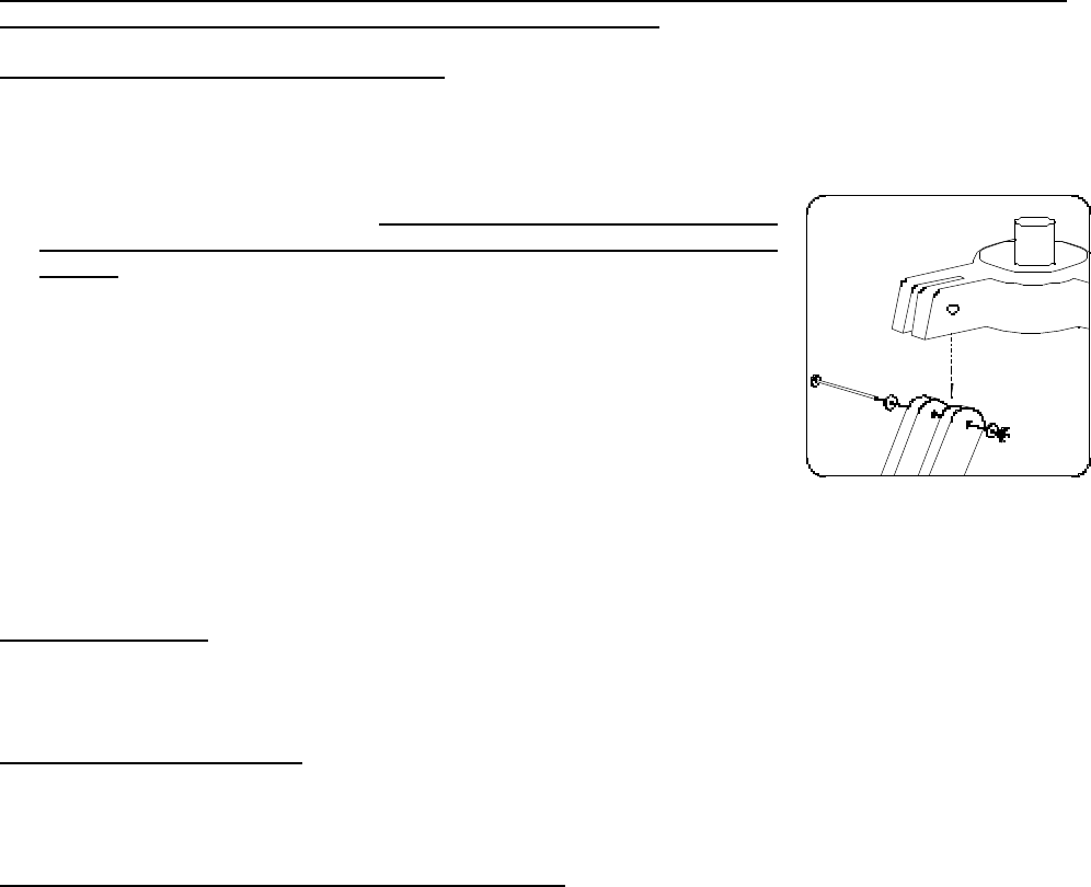
• Locate the Equatorial Mount (22). Note: Before assembling tripod legs
to Equatorial Mount make sure the Accessory Tray Braces (11) face
inward. Locate the long bolts and washers from the hardware pack.
Position the mount over the Tripod Leg as shown (fig. a). and align the
holes in the Tripod Leg with the holes in the mount. Insert the bolts
through the holes at the top of a Tripod Leg (9). A washer should be
positioned on both outer sides of the Tripod Leg. Attach a wing nut to the
bolt, but do not tighten it all the way. Repeat on the remaining two Tripod
Legs. Once you have attached all Tripod Legs to the mount, securely
tighten all wing nuts.
• Locate the Accessory Tray (12). Using the accessory tray bolts, wingnuts
and washers ( 3-_” bolts, 6-_ washers and 3 - wingnuts) connect the Accessory Tray
to the Accessory Tray Braces (11). Start with one Tripod Leg and attach wingnut. Wingnuts should be
positioned beneath the Accessory Tray. Do not tighten wingnuts until all Accessory Tray Braces are
attached as some adjustments may be required.
1. Attach Finderscope
• Locate the Finderscope(20) with pre-assembled Finderscope Mount (21). Remove the two nuts located
near the back of the Telescope Main Tube (2) and place the Finderscope and Mount assembly over the
exposed screws. Replace the nuts, and securely tighten the Finderscope Mount in place.
2. Attach Telescope Main Tube
• Locate the Telescope Main Tube (2). Remove the wingnuts that are attached to the long screws
protruding from beneath the telescope. Position the long screws over the two holes in the Equatorial
Mount (22) and carefully secure the Telescope Main Tube to the Equatorial Mount.
3. Attach Control Cables, Counterweight and Eyepieces
• Locate the Fine Adjustment Cables (14) and the fine adjustment knobs (located in the hardware pack).
Remove the black “Phillips” head screw at the end of the cables. Place the knobs over the
adjustment cable and position so that the holes are aligned. Replace screws and secure tightly.
fig. a
• Loosen the silver screws located at the opposite end of the Fine Adjustment Cables (14). Now, attach
the Fine Adjustment Cables to the two silver posts found on the Equatorial Mount. The first post is
located just above the Declination Lock Knob (3), the second post is located below the Right Ascension
Lock Knob (4).
• Locate the Counterweight (6) and Counterweight Shaft (5). Loosen the
thumb screw located on the Counterweight and slide the Counterweight
onto the Counterweight Shaft and tighten thumb screw to secure the
Counterweight. Thread the Counterweight Shaft into the hole located
directly below the Declination Lock Knob (3). Make sure that the shaft
is securely locked into mount.
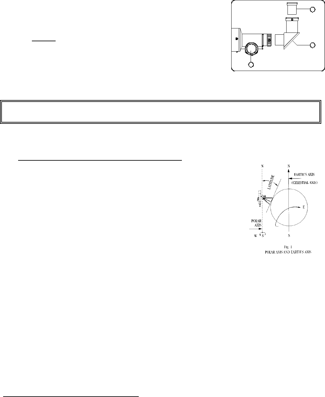
• Locate Eyepiece (17) and Diagonal Mirror (16). Carefully place Eyepiece
into Diagonal Mirror as shown (fig. b)
Your Bushnell telescope is now ready to be used. To obtain the fullest enjoyment
from your telescope, please refer to the additional information below.
III. UNDERSTANDING THE EQUATORIAL MOUNT
The equatorial mount is designed to move in any direction. It can be set to
allow manual controls to track the movements of celestial bodies across the
sky. This is referred to as diurnal movement; movement of celestial bodies in
the direction opposite to that of the earth’s rotation and is around the earth’s
axis.
By aligning the telescope’s polar axis at celestial North, you will place the
telescope in parallel with the earth’s axis and thus be able to locate stars in
the sky based on star atlas information. To compensate for your position on
earth, the polar axis is set in one of three ways:
• Set up the telescope at night. Loosen the Declination Lock Knob (3) and
rotate the telescope around the declination axis until the arrow on the
declination scale points to 90 degrees. Tighten the Declination Lock Knob.
The telescope is now roughly in parallel with the polar axis.
• Loosen the Azimuth Lock Knob (8) and turn the telescope until the objective end faces due north. This
can be done by approximating the location of the pole star (Polaris or North Star) or by the use of a
compass. True North is then found by directing the telescope at Polaris, as magnetic North is slightly
away from true North.
• Look up the latitude of your area in any geographical atlas. Loosen the Altitude Lock Knob (7) and set
the latitude scale to the correct latitude for your area. Aim the Finderscope (20) at Polaris. You will
probably notice that Polaris is not dead center in the finderscope’s field of view. This is probably
because your telescope is not absolutely level with the ground. Loosen the Azimuth Lock Knob (8)
again and turn the telescope so that it is directly aimed at Polaris. Tighten both the Azimuth Lock Knob
and Altitude Lock Knob. Polaris is 1 degree of the North celestial pole. Therefore, the sighting of stars
will have to be slightly adjusted as you locate them in the heavens.
HOW TO USE YOUR NEW TELESCOPE
fig b.
17
16
15
Astronomical telescopes are designed in such a way that the image you will see appear will be UPSIDE DOWN and
REVERSED, this is acceptable for viewing celestial bodies. For land-based viewing an “Erector Lens” is used to
properly re-orient the image.
Selecting an Eyepiece:
1. You should always start viewing with the lowest power eyepiece, which in this case is the 20 mm lens.
Note: the base power of each eyepiece is determined by the focal length of the telescope objective lens,
which for this model is 900 mm. A formula can be used to determine the power of each eyepiece:
telescope OBJECTIVE lens focal length EYEPIECE focal length = MAGNIFICATION (e.g. Using the
20 mm lens, the calculation would look like this: 900 mm ÷ 20mm = 45x or 45 power.)
2. Included with this telescope is a Barlow lens. Barlow lenses are used to double or triple the power of your
telescope. Place your Barlow between the focusing tube and the eyepiece. Using the example above,
your 3x Barlow lens would give you a total power of 135x or 135 power. (45 x 3 = 135x or 135 power)
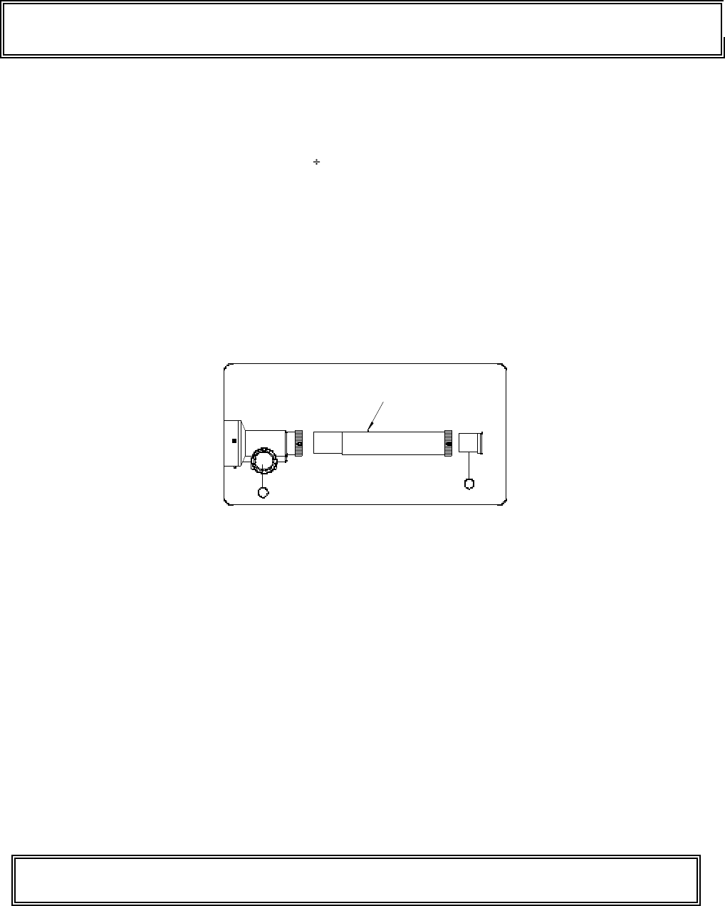
3. Also included with this telescope is an Erecting lens. The Erecting lens is used to view land-based
objects where the correct image orientation is important. The Erecting lens re-orients the telescope image
so that the image you are viewing is properly oriented. Place your Erecting lens between the focusing
tube and the eyepiece (fig. c). It is not recommended to use the Diagonal Mirror (16) with the Erecting lens.
The Diagonal Mirror will make the erected image appear to be “flipped” depending on the orientation of
the diagonal mirror- relative to the telescope.
Focusing Telescope:
1. After selecting the desired eyepiece, aim main telescope
tube at a land-based target at least 200 yards away
(e.g. A telephone pole or building). Fully extend focusing tube by turning Rack and Pinion Focusing
Mechanism (15).
2. While looking through selected eyepiece (in this case the 20 mm), slowly retract focusing tube by turning
Rack and Pinion Focusing Mechanism until object comes into focus.
Aligning Finderscope:
1. Look through Main Telescope Tube (2) and establish a well-defined target. (see focusing telescope section)
Tighten the Altitude Lock Knob (7) and Azimuth Lock Knob (8) so that telescope’s aim is not disturbed.
2. Looking through Finderscope (20), alternate tightening each Finderscope Adjustment Screw (19) until
crosshairs of Finderscope are precisely centered on the same object already centered in main telescope
tube's field of view.
3. Now, objects located first with the Finderscope (20) will be centered in the field of view of the main
telescope.
Never Look Directly At The Sun With Your Telescope
Permanent Damage To Your Eyes May Occur
fig. c
17
15
Barlow or Erecting Lens

Telescope LIFETIME LIMITED WARRANTY
Your telescope is warranted to be free of defects in materials and workmanship for the lifetime
of the original owner. The Lifetime Limited Warranty is an expression of our confidence in the
materials and mechanical workmanship of our products and is your assurance of a lifetime of
dependable service.
If your telescope contains electrical components the electronic components are warranted to be
free of defects in materials and workmanship for one year after the date of purchase.
In the event of a defect under this warranty, we will, at our option, repair or replace the
product, provided that you return the product postage prepaid. This warranty does not cover
damages caused by misuse or improper handling, installation or maintenance of the product.
Any return made under this warranty must be accompanied by the items listed below:
1) A check in the amount of $15.00 to cover the cost of handling
2) Name and address for product return
3) An explanation of the defect
4) Product should be well packed in a sturdy outside shipping carton to prevent
damage in transit and return postage prepaid to the address listed below:
IN U.S.A. Send To:
Bushnell * 8500 Marshall Drive * Lenexa, Kansas 66214
IN CANADA Send To:
Bushnell * 25A East Pearce Street, Unit 1 * Richmond Hill, Ontario L4B 2M9
For products purchased outside the United States and Canada please contact your local dealer
for applicable warranty information. This warranty gives you specific legal rights. You may
have other rights which vary from country to country.
©2001 Bushnell Performance Optics
